Embed Size (px)
Citation preview
Top-down Software Decomposition – An Approachfor Component-based Design Automation
Whitepaper
Ionut Cardei
Department of Computer Science and EngineeringFlorida Atlantic University
Boca Raton, FL 33431
07/21/2006
Abstract
In this whitepaper we summarize the objectives and the technical approach of the Top-down Software Decomposition project and we describe a methodology for improving thequality and reducing the costs of the design process. In our approach product requirementsand component semantics are conceptualized in ontologies,providing semantic descrip-tions that are machine readable and can be processed for consistency checking and modelsynthesis through a process that involves machine reasoning.
This paper also provides a brief summary the main technologies involved in this project.The Model Driven Architecture provides the backdrop for a formal software developmentprocess and for visual modeling tools. We describe the UML and SysML modeling toolsthat are commonly used in the industry for requirements analysis and for software design.The main technologies from the semantic web research domainare covered, such as RDF,RDFS, OWL and reasoning engines.
1 Introduction
This project has focus on improving the architecture designquality, increasing productivityand reducing the cost of the development process. In this whitepaper we present our approachfor automating component-based design through top-down decomposition and we introduceseveral supporting technologies and tools.
We begin by describing the problem we address and the motivation behind our project. Aspart of the system development cycle, a development iteration begins with requirements spec-ification, where marketing specialists and product managers describe functional requirements,technical specifications, features and use cases in naturallanguage, in a semi-formal format,such as MRDs, UML or SysML, or using requirements managementtools such as DOORS
1
[23] or RequisitePro [21]. Following the requirements specification, system architects and en-gineers create a hardware/software architecture design that must fulfill all the requirementsand satisfy any specified constraints. This design stage includes mapping the features, QoSconstraints and behaviors to a component-based (and hierarchical) architecture. This productdecomposition process involves QoS translation (from product to sub-product to componentlevel), matching requirements/constraints to components, and component configuration. Theimplementation and deployment stages follow thereafter.
The transition from requirements to an architecture designis largely done manually with thehelp of UML modeling tools. In most cases designers have available a considerable volumeof pre-existing components and frameworks, from earlier projects or from third parties. Atan abstract level, building a component architecture from requirements is a search in a designspace. With libraries holding hundreds of components, thissearch could take considerable timeand manpower, especially when requirements are updated frequently or what-if exploration andtrade-off analyses are performed.
This project aims to reduce the cost of system design by automating the process of archi-tecture decomposition from existing component libraries.Specifically, our goal is to build amethodology that assists designers by matching product requirements with component capa-bilities to
• find component structures that satisfy requirements
• track components to requirements
• check requirements consistency
• produce component configurations.
This project uses industry standards, such as the Unified Modeling Language (UML) [19], theSystem Modeling Language (SysML) [16], and XML Metadata Interchange (XMI) [20] andcomplies with widely used UML modeling tools, such as Rhapsody [12].
1.1 Top-down Software Decomposition in the OPP Context (theBig Pic-ture)
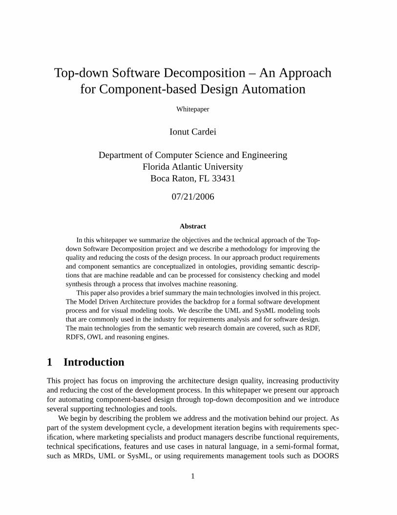
The Top-down Software Decomposition project is positionedin the overall OPP design processas bridging the requirements specification phase and the modeling/design phase, as shown inFig. 1. Our methodology is used to describe requirements formally, and to define the capa-bilities and constraints of components. We will integrate our work with the results from theOPP “Specification Productivity” project, that addresses requirements specification for sup-porting model animation. The Top-down Software Decomposition project provides tools forprocessing (a) requirements in a formal representation and(b) component metadata to buildand configure UML structural models that can be used directlyin the design/modeling phases.The generated UML models will be either saved in XMI or automatically edited inside an UMLmodeling tool that supports a model access API (e.g. Eclipseor Rhapsody).
2
Figure 1: The Top-down Software Decomposition framework positioned in the overall OPPdesign process.
1.2 Ontology-based Technical Approach
The key to our solution is to close the semantic gap between requirements and componentsby using compatible semantic models for describing both product requirements and compo-nent capabilities, including constraints. A domain-specific representation language is designedthat spans the application domain (cell phones), the software design domain (UML/SysMLmetaschema) and the component domains. This OPP Design Language (ODL) is used to rep-resentontologies, textual representation (stored in files) that captures thesemantic elementscommon to product requirements and design modeling, and provides the glue between them.
Ontologies encode domain-specific concepts and the relationships between them providinga vocabulary and a computerized specification of the meaningof terms used in the vocabulary.The ODL is defined using the Ontology Web Language (OWL), a logic-based language stan-dardized by the W3C [27]. OWL has an XML encoding and has wide support in the semanticweb community. Domain-specific ontologies written with ODLare also OWL ontologies andcan be used for automated reasoning.
According to [11] ontologies can be very useful in software engineering projects wheredevelopment is focused not just on one application, but on a family of projects from the samedomain, as ontologies extend the idea of reuse from implementations (code) to the modelinglevel. This modeling approach is productive inModel-Driven Development(MDD), a mod-ern paradigm that puts models at its core of its development process. For projects that covernew domains, ontologies must be developed in a new taxonomy framework to describe the
3
new concepts, properties, and relationships of the concerndomains. The scope and general-ity of ontologies must be negotiated between stakeholders.For projects building on existingconceptual frameworks, existing ontologies can be used forlaying out the analysis model. Def-initions from the existing ontologies can be enriched and new elements can be added that arecompatible with existing ontologies (condition called ontological commitment).
In the OPP project we target the development of mobile systems and applications, coveringthe domains of cell phone system architecture (hardware) and mobile applications (software).As the full scope of these domains is exceedingly large for the scope of the Top-down SoftwareDecomposition project, we develop prototype ontologies with limited scope for both domainsthat address a particular case study (an application for location-based services) and we providea methodology for refining and extending ontologies by qualified personnel.
The input to our methodology consists of: (a) component and UML classifier metadatain ODL (for classes, interfaces, UML components) describing semantics, such as capabilitiesand constraints, (b) UML models in XMI from which additionalknowledge and relationshipsbetween components and classifiers are automatically extracted (e.g. dependencies, interfaces,associations) and (c) requirements specified in the formal ODL language capturing mostlyfunctional aspects, such as (sub)product features, constraints and QoS.Note: a generic mechanism for extracting ODL ontologies from product requirements is be-yond the scope of the Top-down Software Decomposition project. This is a challenging issuethat needs further discussion with Motorola.
Our methodology produces: (a) partial UML structural diagrams, (b) component configurationfiles (XML) and (c) reports on requirements consistency. Theoverall design methodologydescribed above is illustrated in Figure 2.The main steps of the Top-down Software Decomposition methodology are:
ODL DefinitionThe ODL is the language for describing ontologies for the these problem domains: mobileapplications, cell phone systems, hw/sw components and MOFmetaschema (for components).This language is defined initially by the Top-down Software Decomposition team and extendedlater by domain experts to cover an increasing scope. The ODLlanguage actually consists of aseries of domain-specific OWL ontologies. Details on the ODLfollow in section 3.1. Protege[2] is an ontology modeling tool that will be used for definingODL.
Requirements SpecificationA recurring step in our methodology is application requirements specification by market-ing and product management. In our vision, they would use a modeling tool that generatesODL ontologies encoding requirements. This can be achievedby compiling UML/SysML re-quirements models (usecase/activity/requirements/parametric/interaction) or by using domain-specific UML 2.0 profiles or Domain Specific Modeling tools that support requirements mod-eling and export ODL ontologies viamodel transformation(see section 4). In the limited scopeof this project we assume requirements are expressed as ODL ontologies. Please read more insection 4 about requirements engineering with ontologies.
4
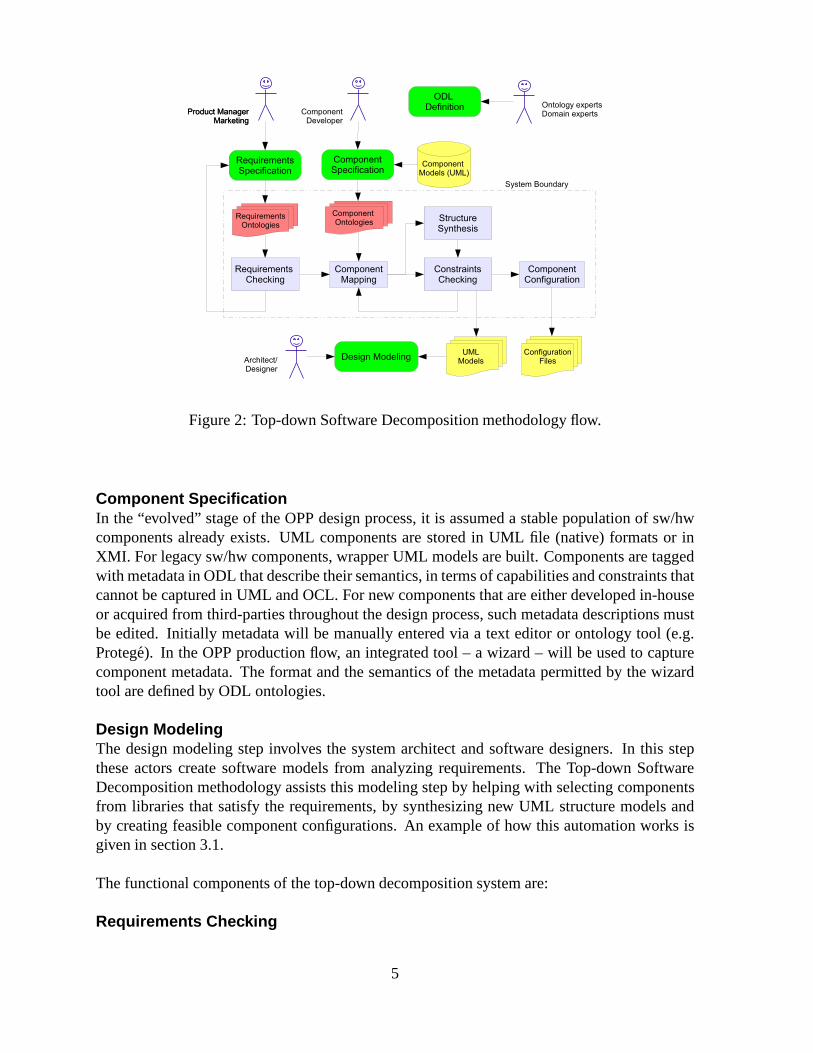
Figure 2: Top-down Software Decomposition methodology flow.
Component SpecificationIn the “evolved” stage of the OPP design process, it is assumed a stable population of sw/hwcomponents already exists. UML components are stored in UMLfile (native) formats or inXMI. For legacy sw/hw components, wrapper UML models are built. Components are taggedwith metadata in ODL that describe their semantics, in termsof capabilities and constraints thatcannot be captured in UML and OCL. For new components that areeither developed in-houseor acquired from third-parties throughout the design process, such metadata descriptions mustbe edited. Initially metadata will be manually entered via atext editor or ontology tool (e.g.Protege). In the OPP production flow, an integrated tool – a wizard – will be used to capturecomponent metadata. The format and the semantics of the metadata permitted by the wizardtool are defined by ODL ontologies.
Design ModelingThe design modeling step involves the system architect and software designers. In this stepthese actors create software models from analyzing requirements. The Top-down SoftwareDecomposition methodology assists this modeling step by helping with selecting componentsfrom libraries that satisfy the requirements, by synthesizing new UML structure models andby creating feasible component configurations. An example of how this automation works isgiven in section 3.1.
The functional components of the top-down decomposition system are:
Requirements Checking
5
This component validates consistency of the requirements specified in ODL. It checks for anycontradictions and verifies whether any elements are missing from an existing specification.This is possible since ODL ontologies provide a metamodel specifying functional require-ments, QoS requirements, and constraints.
Component MappingValidated requirement ontologies and component specifications expressed in ODL statementsare compiled into facts and passed to a reasoning engine thatattempts to match componentswith requirements. The result from this step are sets of components andfeasibleconfigurationsthat match the requirements, and reports of failures with descriptions of the mapping failurereasons.
Structure SynthesisThe previous component mapping step continues with this structure synthesis step where UMLstructure diagrams (class, block, component diagrams) areassembled to model higher levelcomponents that satisfy the requirements.
Constraints CheckingThe newly assembled structures and the selected componentsare checked for consistency.Here, any exterior inter-component constraints can be verified, e.g. concurrency and resourceconstraints.
Component ConfigurationOnce components are selected and higher-level structure assembled, this step generates component-specific configuration files for deployment. Parameter values are selected from feasible regionsspecified by the requirements and matched by the component parameter space.
The system architecture and the main methodology components are described in section 3.The paper presents in the next section the technologies considered in this project. Section
3 describes the top-down decomposition methodology. Section 5 summarizes the paper with adiscussion and conclusions.
2 Background
In this section we examine briefly several technologies thatare relevant for OPP and this projectand relate to software development and semantic modeling.
2.1 Model Driven Architecture
Software development has struggled for a long time to reach the level of productivity, qualityand predictability achieved in other engineering domains.One approach advocated by the Ob-ject Management Group (OMG) is the Model Driven Architecture (MDA) [18]. MDA supportsmodel-driven engineering of software systems and providesguidelines for specifying systemstructures as models. MDA separates the fundamental logic behind a specification – the Plat-form Independent Models (PIM) – from the specifics of the particular system that implements
6
it – the Platform Specific Model (PSM).A complete MDA specification consists of a base PIM, one or more PSMs, plus sets of
interface definitions that describe how the base PIM is implemented on a different platforms. Acomplete MDA application consists of a definitive PIM, plus one or more PSMs and completeimplementations, one for each platform selected by the application developer.
The underlying mechanism for defining PIMs is the Meta ObjectFacility (MOF). The MOFis MDA’s foundation specification for modeling languages; MOF compliance allows UMLstructural and behavioral models to be transmitted via XMI [20], stored in MOF-compliantrepositories, and transformed and manipulated by MOF-compliant tools and code generators.The UML is used for building models that comply with the MOF.
Although MDA was developed primarily for distributed systems, its methodology andmodel technologies are relevant to the OPP project. Maintaining software application frame-works and components during their lifetime on soft/hardware platforms that keep evolving canbe a daunting task. MDA PIMs separate the application logic from the platform specific details.This separation simplifies porting an application to a new platform, as only a PSM is required,which is independent from the application.
An introduction to MDA is available online [5]. [15] lists MDA tools and products.
2.2 The Unified Modeling Language
UML [19] was designed by the OMG to assist software developers to specify, visualize, anddocument models of software systems, including their structure, behavior and designs. UMLprovides a standardized graphical notation that developers use to build an abstract model of asystem, also called the UML model.
The recent revision of the language, UML 2.0, added extensibility to the language intro-ducing a profile mechanism to customize the language. New concepts can be introduced to thelanguage by defining a stereotype. UML version 2.0 defines thirteen types of diagrams, dividedinto three categories: six diagram types represent static application structure; three representgeneral types of behavior; and four represent different aspects of interactions:
Structure Diagrams include the Class Diagram, Object Diagram, Component Diagram, Com-posite Structure Diagram, Package Diagram, and DeploymentDiagram.
Behavior Diagrams include the Use Case Diagram (used for requirements gathering); Activ-ity Diagram, and State Machine Diagram.
Interaction Diagrams derived from the more general Behavior Diagram, include theSe-quence Diagram, Communication Diagram, Timing Diagram, and Interaction OverviewDiagram.
UML has been criticized for being difficult to learn, very complex and having imprecisesemantics. UML is ineffective when developers must maintain manually synchronize diagramswith code, as this may lead to inconsistencies. Ideally, UMLtools should generate all imple-mentation code from UML diagrams.
UML developers may use the declarativeObject Constraint Language(OCL) to describerules that apply to UML models. The OCL is a precise text language that provides constraint
7
and object query expressions on any Meta-Object Facility model or metamodel that cannototherwise be expressed by diagrammatic notation.
For the OPP project, we assume UML will continue to be the language of choice at Mo-torola for system architecture design. UML has a wide user base and is supported by manytools, such as I-Logix Rhapsody [12], IBM/Rational Software Architect and Modeler [13],Telelogic System Architect/Developer [24] and Eclipse [7]. A comprehensive list of UML 2.0tools is available from the OMG at [17].
In this project we will continue to use Rhapsody, as it provides support for UML 2.0, OCL,XMI import/export, SysML and has extensive features for development of real-time applica-tions. We will also consider Eclipse, that has the advantageof being open-source, with publiclyavailable plug-in interfaces. The top-down decompositionmethodology will initially work withXMI, and Eclipse would later provide the least cost path to integration with a modeling tool.See section?? for more details.
2.3 The System Modeling Language
The SysML (Systems Modeling Language) [16] is a domain-specific visual language for sys-tems engineering applications, adopted by the OMG in 07/06.It supports the specification,analysis, design, verification and validation of a broad range of systems and systems-of-systems.These systems may include hardware, software, information, processes, personnel, and facili-ties.
SysML is defined as a UML 2.0 profile and reuses the notations and semantics of UML2.0 diagrams. The advantages of this are: (a) SysML can be used together with UML in thesame projects to address systems engineering aspects, (b) SysML is extensible using UML’sprofile and stereotype mechanisms, (c) familiarity for UML users, (d) growing support fromthe UML community. Unfortunately, SysML also inherits UML’s problems with lack of formalsemantics, bloat and complex notation.
SysML reuses seven diagrams from UML 2.0, with slightly different semantics, and intro-duces two new diagrams. We are interested in SysML for its capability to express system-leveldesign concepts and for its support for requirements management with two new diagrams:
Parametric diagram : shows parametric constraints between structural elements. Useful forperformance and quantitative analysis.
Requirement diagram : shows system requirements and their relationships with other ele-ments. Useful for requirements engineering.
A SysML parametric diagram developed with Rhapsody is depicted in Figure 3. The diagramdescribes the constraints and arithmetic relationships defined between system attributes for amobile phone management application.
SysML has support from I-Logix, Telelogic, IBM, Mentor Graphics, PivotPoint Technol-ogy Corporation, Sparx Systems, Vitech Corp and other. Popular tools that integrate SysMLare Rhapsody and Telelogic TAU. For more information on the language, please consult theweb references [16] and [10].
8
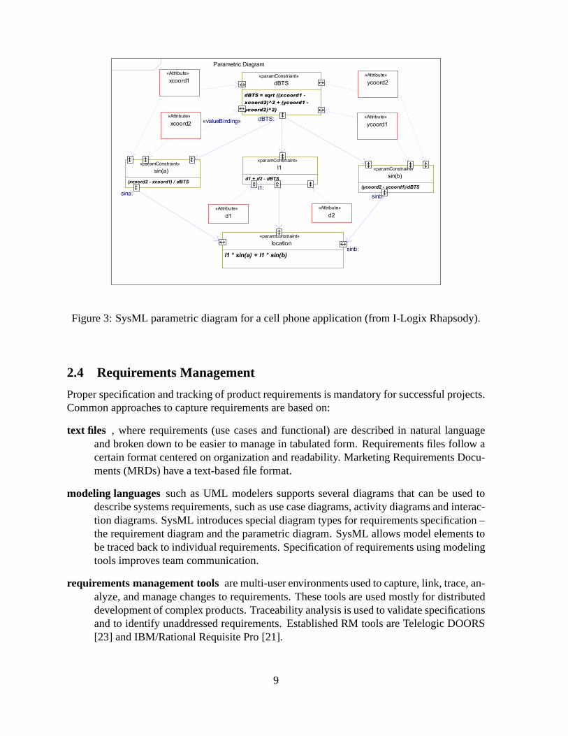
Figure 3: SysML parametric diagram for a cell phone application (from I-Logix Rhapsody).
2.4 Requirements Management
Proper specification and tracking of product requirements is mandatory for successful projects.Common approaches to capture requirements are based on:
text files , where requirements (use cases and functional) are described in natural languageand broken down to be easier to manage in tabulated form. Requirements files follow acertain format centered on organization and readability. Marketing Requirements Docu-ments (MRDs) have a text-based file format.
modeling languagessuch as UML modelers supports several diagrams that can be used todescribe systems requirements, such as use case diagrams, activity diagrams and interac-tion diagrams. SysML introduces special diagram types for requirements specification –the requirement diagram and the parametric diagram. SysML allows model elements tobe traced back to individual requirements. Specification ofrequirements using modelingtools improves team communication.
requirements management toolsare multi-user environments used to capture, link, trace, an-alyze, and manage changes to requirements. These tools are used mostly for distributeddevelopment of complex products. Traceability analysis isused to validate specificationsand to identify unaddressed requirements. Established RM tools are Telelogic DOORS[23] and IBM/Rational Requisite Pro [21].
9
For our project, we need to define a semantic bridge between requirements and components.From the methods above only SysML and UML 2.0 manage to partially describe requirementssemantics in a formal, machine-readable format, when described with OCL.
As part of our methodology, we develop domain-specific ontologies for describing require-ments semantics with the ODL language. UML/SysML requirements models will be usedto compile ODL files with specific requirements. Additional semantic information must becaptured by the user for aspects not covered by SysML/UML.
Capturing semantics from requirements can be simplified andbetter automated in case thedesign team uses UML 2.0 profiles specialized for the problemdomain orDomain SpecificModeling Languages(DSML). DSMLs formalize the application requirements, architecture,and the behaviors of specific domains (e.g. cell phone applications avionics, grid computing,banking). DSMLs are specified with metamodels that precisely define the semantics of do-main concepts, capabilities, concepts and the relationships between concepts. For more aboutDSMLs consult the documents at the DSM Forum [9].
Domain-specific UML 2.0 profiles or a DSML provide the following benefits: (a) define anunequivocal semantic for domain concepts, (b) reduce bloatand confusion by restricting thedomain vocabulary, (c) optimize expressiveness for the target domain, and (d) high degree ofcode generation and better code quality.
2.5 Semantic Modeling
A key element of our methodology for top-down decompositionis to describe the semanticsof requirements and components. Beginning in the late 1990sthe World Wide Web Consor-tium (W3C) began developing knowledge representation and processing mechanisms for theinternet. The work led by Tim Berners-Lee on the Semantic Webproject [31] has resultedin a series of standardized languages designed for operation in a distributed network, such asinternet. These have garnered wide support from the industry and tool developers. The W3Csemantic web languages present the advantage (when compared with older knowledge repre-sentation techniques) that they can support development ofdistributed knowledge bases withtheir capacity of referring to remote resources via Unified Resource Identifiers combined withnetwork transfers.
2.5.1 The Resource Description Framework and the RDF Schema
The Resource Description Framework (RDF) [30] was designedprimarily to represent meta-data for web resources. RDF is based on XML and was designed onthe idea that informationon the web can be represented in statements that describe things by the properties they have:
<subject> <property> <object>
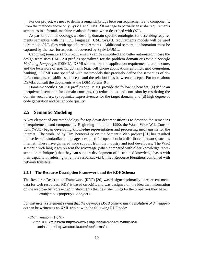
For instance, a statement saying thatthe Olympus D510 camera has a resolution of 3 megapix-elscan be written as an XML triplet with the following RDF code:
<?xml version=’1.0’?>
<rdf:RDF xmlns:rdf=’http://www.w3.org/1999/02/22-rdf-syntax-ns#’xmlns:opp=’http://motorola.com/opp/terms/’>
10
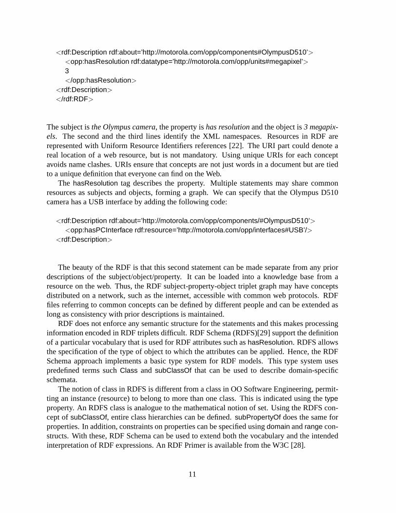
<rdf:Description rdf:about=’http://motorola.com/opp/components#OlympusD510’><opp:hasResolution rdf:datatype=’http://motorola.com/opp/units#megapixel’>3</opp:hasResolution>
<rdf:Description>
</rdf:RDF>
The subject isthe Olympus camera, the property ishas resolutionand the object is3 megapix-els. The second and the third lines identify the XML namespaces.Resources in RDF arerepresented with Uniform Resource Identifiers references [22]. The URI part could denote areal location of a web resource, but is not mandatory. Using unique URIs for each conceptavoids name clashes. URIs ensure that concepts are not just words in a document but are tiedto a unique definition that everyone can find on the Web.
The hasResolution tag describes the property. Multiple statements may share commonresources as subjects and objects, forming a graph. We can specify that the Olympus D510camera has a USB interface by adding the following code:
<rdf:Description rdf:about=’http://motorola.com/opp/components/#OlympusD510’><opp:hasPCInterface rdf:resource=’http://motorola.com/opp/interfaces#USB’/>
<rdf:Description>
The beauty of the RDF is that this second statement can be madeseparate from any priordescriptions of the subject/object/property. It can be loaded into a knowledge base from aresource on the web. Thus, the RDF subject-property-objecttriplet graph may have conceptsdistributed on a network, such as the internet, accessible with common web protocols. RDFfiles referring to common concepts can be defined by differentpeople and can be extended aslong as consistency with prior descriptions is maintained.
RDF does not enforce any semantic structure for the statements and this makes processinginformation encoded in RDF triplets difficult. RDF Schema (RDFS)[29] support the definitionof a particular vocabulary that is used for RDF attributes such ashasResolution. RDFS allowsthe specification of the type of object to which the attributes can be applied. Hence, the RDFSchema approach implements a basic type system for RDF models. This type system usespredefined terms suchClass and subClassOf that can be used to describe domain-specificschemata.
The notion of class in RDFS is different from a class in OO Software Engineering, permit-ting an instance (resource) to belong to more than one class.This is indicated using thetypeproperty. An RDFS class is analogue to the mathematical notion of set. Using the RDFS con-cept ofsubClassOf, entire class hierarchies can be defined.subPropertyOf does the same forproperties. In addition, constraints on properties can be specified usingdomain andrange con-structs. With these, RDF Schema can be used to extend both thevocabulary and the intendedinterpretation of RDF expressions. An RDF Primer is available from the W3C [28].
11
2.5.2 The Ontology Web Language
The Ontology Web Language (OWL) [27, 3] is used to explicitlyrepresent the meaning ofterms in vocabularies and the relationships between those terms. Thus, OWL can be used tospecify ontologies, as defined in section 1. On the semantic web, the termontologyis alsoused for a document or a file that formally defines the relations between concepts in a specificdomain. The most typical kind of ontology for the Web has a taxonomy and a set of inferencerules. A taxonomy defines classes of objects and the relations among them.
For instance acell phone is a type of amobile terminal, and a mobile terminal has aloca-tion. Relations between entities can be expressed easier if properties are assigned to classes andsubclasses can inherit them. We can infere that acell phonealso inherits thelocationproperty.With inference, even more information can be extracted fromexisting ontologies. For instance,assume afrequency allocationcalledFA requires that, in a specificlocationcalledL, only achannelC must be used. A reasoning engine would infer that it a cell phone associated withlocationL must switch to channelC.
RDF is used to build data models between objects (resources)and relationships (properties)between them. This model only support simple semantics. RDFSchema defines vocabulariesfor describing properties and classes of RDFS objects supporting creation of class and propertyhierarchies. OWL adds additional vocabulary terms for describing properties and classes, suchas relations between classes (e.g. disjointness, union, intersection), cardinality constraints (e.g.”exactly one”), equality, more types of properties, enhanced characteristics of properties (e.g.symmetric, functional and inverse functional), and enumerated classes.
OWL comes in three variants: (a) OWL Full gives maximum expressiveness and the syn-tactic freedom of RDF with no computational guarantees, (b)OWL-DL includes all OWLlanguage constructs, with several restrictions: while a class may be a subclass of many classes,a class cannot be an instance of another class), and (c) OWL-Lite supports those users primar-ily needing a classification hierarchy and simple constraints. For practical reasons OWL-DLprovides the best compromise between decidability and expressivity, being supported by manyreasoning engines.
In our project we use OWL to define a vocabulary (ontology) of terms from the followingdomains: cell phone application requirements, system and software components, and a subsetof MOF for describing the design model (UML). The vocabularywe propose is called theOPP Design Language (ODL) and describes instances of classes from these domains and theirproperties. ODL files are also called ontologies.
2.5.3 Reasoning and Semantic Models
Ontology languages allow users to write explicit, formal conceptualizations of domains mod-els. The main requirements for ontology languages are (from[3]):1. a well-defined syntax2. a well-defined semantics3. efficient reasoning support4. sufficient expressive power5. convenience of expression.
12
A formal semantics describes the meaning of the knowledge, which must be unequivocal forboth people and machine to make reasoning possible. A reasoner infers new information onclass membership, class equivalence and checks consistency of instance class membership.Additional rules can be defined that change the contents of the knowledge base depending onexisting instances.
For the Top-down Software Decomposition project reasoningis used to perform the searchin the design space based on requirements and components specifications. The reasoning en-gine will derive new knowledge and answer queries from the main application. Mainly, reason-ing can: (a) check consistency of knowledge base (ontologies), (b) validate relations betweenclasses, (c) automatically classify instances into classes.
Reasoning with OWL ontologies has the advantage of integrating knowledge bases (ontolo-gies) from different sources from the web and from differentauthors, provided new informationdoes not contradict existing ontologies. We now survey several reasoning platforms compatiblewith OWL, that can be used in the Top-down Software Decomposition project.
Jena, A Semantic Web Framework for JavaJena [14], developed by the HP Labs Semantic Web Programme, is a Java framework forbuilding Semantic Web applications. It provides a programmatic environment for RDF, RDFS,OWL, SPARQL (a semantic web query language) and includes a rule-based inference engine.Jena is open source and has been used for developing many knowledge processing applications.
The Jena Framework includes: an RDF Java API, reading and writing RDF in RDF/XML,N3 and N-Triples, an OWL API, in-memory and persistent storage, a SPARQL query engine,support for pluggable query engines and building inferenceengines. Jena provides most fea-tures needed for a knowledge processing application on the semantic web. In addition, Jenaprovides a tool for generating Java classes from OWL/RDFS vocabularies. Jena comes with 4builtin reasoners, including a generic rule reasoner with backward chaining. Backward chain-ing is an inference technique that starting from a goal statement can return the necessary factsthat support the proof. For the Top-down Software Decomposition project, Jena is used forprototyping the decomposition driver and consistency checking.
Jess, the Rule Engine for JavaJess [1] is a rule engine and scripting environment written in Java that reasons on knowledgeprovided in form of declarative rules. The user specifies rules in a text based or an XML-basedformat and data (facts). The rule engine tries to match ruleswith the data. Matched rulesfireex-ecuting prescribed actions and possibly changing the knowledge base by adding/remove/changingavailable facts.
Jess uses a language compatible with the CLIPS system [6] andfeatures a scripting enginethat permits calling Java code from rules, and access to the knowledge base from Java code.The drawback of Jess is that it supports OWL only via an external ontology compiler.
ProtegeProtege [2] is an open source ontology editor and knowledge-base framework developed atStanford that supports OWL and a custom frame-based ontology format. Protege is writtenin Java, has a plugin framework that is extensible, support aJava API and implements a richset of knowledge-modeling structures and actions that support the creation, visualization, and
13
manipulation of ontologies in various representation formats.
Protege enables users to:- Load and save OWL and RDF ontologies.- Edit and visualize classes, properties and SWRL rules.- Define logical class characteristics as OWL expressions.- Execute reasoners such as description logic classifiers (Jess).- Edit OWL individuals for Semantic Web markup.
We will use Protege in our project to define the ODL vocabulary and write the ODL ontolo-gies (OWL instances and properties). The Jess plugin will help us prototype processing rulesand evaluate our approach.
3 The Architecture for Top-down Software Decomposition
This section describes our approach for top-down decomposition . From section 1, we reiterateour project goals to build a methodology that assists designers by matching product require-ments with component capabilities to:
• find component structures that satisfy requirements
• track components to requirements
• check requirements consistency
• produce component configurations.
We begin by reviewing the high-level system architecture, shown in Figure 4.
The OPP Design LanguageThe OPP ontology design language (ODL) is implemented by experts in ontologies workingtogether with experts in the domains of software design (MOF), cell phone application require-ments and components.UML/SysML RequirementsProduct requirements are described by product managers andmarketing people in a modelinglanguage and translated by our system to ODL ontologies fromXMI. Incomplete informationfrom requirements must be entered using a wizard mechanism.From UML/SysML models,the knowledge extraction step applies transformation rules to compile ODL ontologies that canbe processed by the reasoner.
UML/SysML ComponentsComponents from libraries are tagged with ODL ontologies (model metadata) that describe se-mantics not covered by UML/SysML. The remainder of component semantic data is extracteddirectly from the UML/SysML model diagrams, such as relationships, attributes, interfaces,ports, etc. The component models are stored in XMI format on afilesystem or in a database.
14
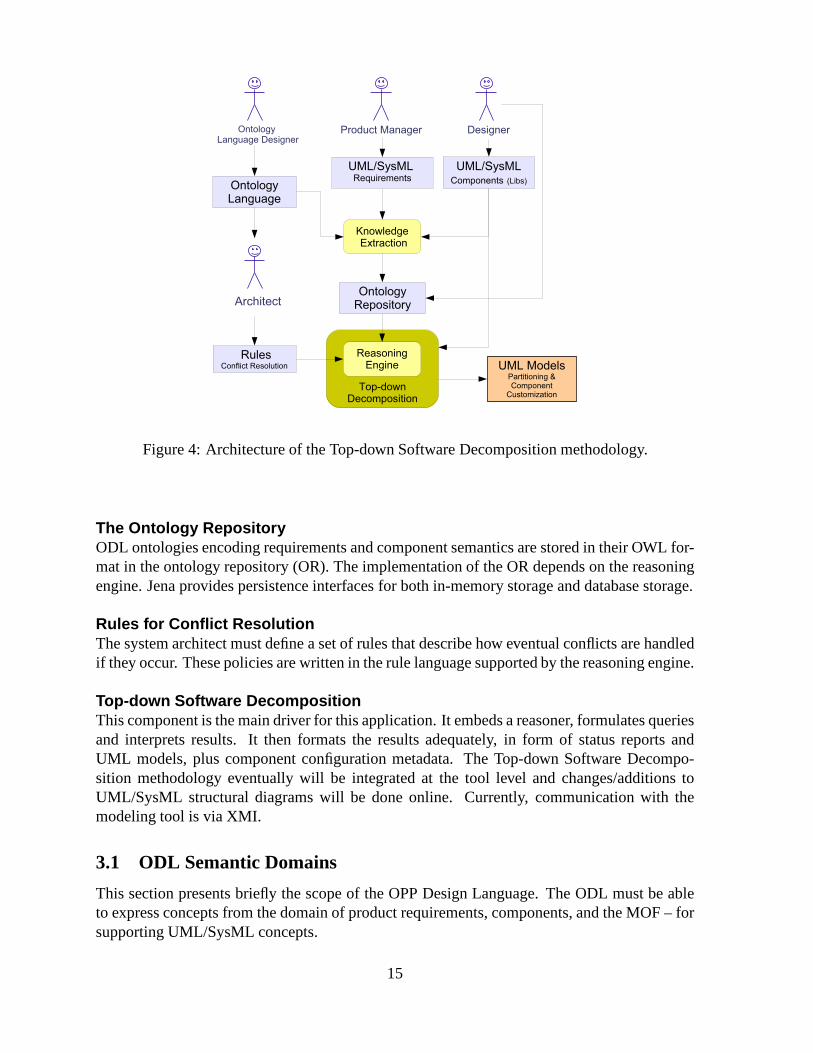
Figure 4: Architecture of the Top-down Software Decomposition methodology.
The Ontology RepositoryODL ontologies encoding requirements and component semantics are stored in their OWL for-mat in the ontology repository (OR). The implementation of the OR depends on the reasoningengine. Jena provides persistence interfaces for both in-memory storage and database storage.
Rules for Conflict ResolutionThe system architect must define a set of rules that describe how eventual conflicts are handledif they occur. These policies are written in the rule language supported by the reasoning engine.
Top-down Software DecompositionThis component is the main driver for this application. It embeds a reasoner, formulates queriesand interprets results. It then formats the results adequately, in form of status reports andUML models, plus component configuration metadata. The Top-down Software Decompo-sition methodology eventually will be integrated at the tool level and changes/additions toUML/SysML structural diagrams will be done online. Currently, communication with themodeling tool is via XMI.
3.1 ODL Semantic Domains
This section presents briefly the scope of the OPP Design Language. The ODL must be ableto express concepts from the domain of product requirements, components, and the MOF – forsupporting UML/SysML concepts.
15
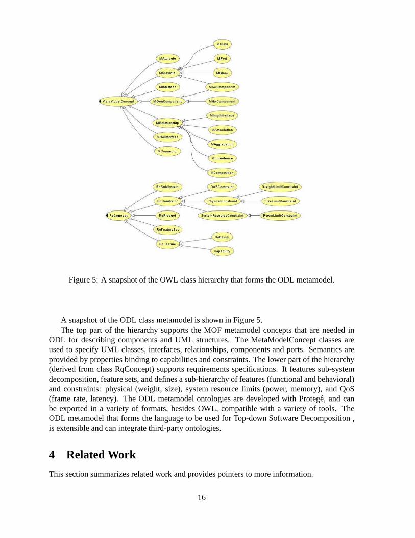
Figure 5: A snapshot of the OWL class hierarchy that forms theODL metamodel.
A snapshot of the ODL class metamodel is shown in Figure 5.The top part of the hierarchy supports the MOF metamodel concepts that are needed in
ODL for describing components and UML structures. The MetaModelConcept classes areused to specify UML classes, interfaces, relationships, components and ports. Semantics areprovided by properties binding to capabilities and constraints. The lower part of the hierarchy(derived from class RqConcept) supports requirements specifications. It features sub-systemdecomposition, feature sets, and defines a sub-hierarchy offeatures (functional and behavioral)and constraints: physical (weight, size), system resourcelimits (power, memory), and QoS(frame rate, latency). The ODL metamodel ontologies are developed with Protege, and canbe exported in a variety of formats, besides OWL, compatiblewith a variety of tools. TheODL metamodel that forms the language to be used for Top-downSoftware Decomposition ,is extensible and can integrate third-party ontologies.
4 Related Work
This section summarizes related work and provides pointersto more information.
16
Domain-Specific Modeling is an effective mechanism for improving the design productiv-ity considerably, since all concepts and diagrams are optimized for the specific domain. Aplatform for building domain-specific modeling tools is theGeneric Modeling Environmentfrom Vanderbilt [26]. The configuration is accomplished through metamodels specifying themodeling paradigm (modeling language) of the application domain. The modeling paradigmcontains all the syntactic, semantic, and presentation information regarding the domain; whichconcepts will be used to construct models, what relationships may exist among those concepts,how the concepts may be organized and viewed by the modeler, and rules governing the con-struction of models. The modeling paradigm defines the family of models that can be createdusing the resultant modeling environment.
The metamodeling language is based on the UML class diagram notation and OCL con-straints. The metamodels specifying the modeling paradigmare used to automatically generatethe target domain-specific environment. The generated domain-specific environment is thenused to build domain models that are stored in a model database or in XML format. Thesemodels are used to automatically generate the applicationsor to synthesize input to differentCOTS analysis tools.
Another approach for increasing design productivity is through model transformation. Amodel transformation takes as input a model conforming to a given metamodel and producesas output another model conforming to a given metamodel. OMGhas proposed QVT (Queries/Views/Transformations) [4]. QVT defines a standard way to transform source models into tar-get models. There are several ideas in this proposal. One is that the source and target modelsmay conform to arbitrary MOF metamodels. Another one is thatthe transformation programis considered itself as a model, and as a consequence also conforms to a MOF metamodel.
A good study of use of ontologies in software engineering is given by Hesse in [11]. Theauthor has some interesting conclusions. Ontology development as part of a software projectmust proceed in parallel and with a wider horizon. Usually, ontologies will address multipleprojects and will span several teams. An interesting interaction between ontology and softwaredevelopment is noticed: that system analysis implies the investigation of existing ontologiesand the transfer of codified knowledge for the application domain being considered, and sys-tem implementation and operational use imply feedback of the project results and experiencesto the ontology developers/maintainers and have to be incorporated there in order to keep theontology alive. In addition, ontologies can be used for transferring knowledge from project toproject and to promote communication.
The W3C workgroup note from [25] gives a detailed survey on ontology driven architec-tures and uses of the semantic web in Systems and Software Engineering. The authors coverespecially the area of Knowledge-based Software Engineering. Several interesting ideas arecontemplated: (1) use the semantic web as a tool for classification or as a mechanism for “rig-orously describing, identifying, discovering and sharingartifacts amongst discrete subsystems,systems and systems’ design teams both during design and at runtime”; (2) use ontologies forformal model specification due to the unambiguous qualitiesof information representation ofthe semantic web; (3) software lifecycle support; and (4) use the semantic web as a system for“ for runtime information and artifact sharing“. The last concept is followed by our Top-down
17
Software Decomposition project. We use semantic web runtime capabilities for manipulatingknowledge to improve design quality and reduce costs.
Finally, the work in [8] proposes an architecture for onlinesemantic-based service compo-sition in applications with sensor networks. While this is avery different domain from OPP, theapproach for synthesizing higher level services from lowerlevel services provided the technicalinspiration for our project.
5 Conclusions
In this whitepaper we summarize the objectives and the technical approach of the Top-downSoftware Decomposition project and we describe a methodology for improving the design andfor reducing the costs of the design process. The main idea behind our approach is to de-scribe product requirements and component semantics with acommon language that supportsautomated reasoning on knowledge from both domains.
We also survey the main technologies involved in this project. The Model Driven Architec-ture provides the backdrop for a formal software development process and for visual modelingtools. We describe the UML and SysML modeling tools that are commonly used in the indus-try for requirements analysis and for software design. The main semantic technologies fromthe semantic web are also covered: RDF, RDFS, OWL and severalreasoning engines.
References
[1] Jess, the rule engine for Java. http://www.jessrules.com.
[2] Protege: ontology editor and knowledge-base framework. protege.stanford.edu.
[3] G. Antoniou and F. van Harmelen.Handbook on Ontologies in Information SystemsHand-book on Ontologies in Information Systems, chapter Web Ontology Language: OWL.Springer-Verlag, 2003. http://jeogoodjob.250free.com/data/OntoHandbook03OWL.pdf.
[4] M Bohlen. Qvt and multi metamodel transformation in mda.http://galaxy.andromda.org/jira/secure/attachment/10780/QVT+article+mbohlen+2006.pdf.
[5] Alan Brown. An introduction to Model Driven Architecture. http://www-128.ibm.com/developerworks/rational/library/3100.html.
[6] CLIPS. A tool for building expert systems. http://www.ghg.net/clips/CLIPS.html.
[7] Eclipse. EMF-based UML 2.x Metamodel Implementation.http://www.eclipse.org/uml2/.
[8] Kamin Whitehouse et al. Semantic streams: a framework for declarative queriesand automatic data interpretation. Technical report, Microsoft Research, 2005.ftp://ftp.research.microsoft.com/pub/tr/TR-2005-45.pdf.
18
[9] The Domain-Specific Modeling Forum. http://www.dsmforum.org/.
[10] The SysML Forum. http://www.sysmlforum.com/.
[11] Wolfgang Hesse. Ontologies in the software engineering process. In R. Lenz et al., editor,EAI 2005 - Tagungsband Workshop on Enterprise Application Integration, 2005.
[12] I-Logix/Telelogic. The Rhapsody UML Modeling Tool.http://www.ilogix.com/sublevel.aspx?id=53.
[13] IBM/Rational. Rational Software Architect. http://www-306.ibm.com/software/awdtools/architect/swarchitect/index.html.
[14] Jena. A semantic web framework for java. http://jena.sourceforge.net.
[15] OMG. MDA committed companies and their products.http://www.omg.org/mda/committed-products.htm.
[16] OMG. Omg systems modeling language. http://www.omgsysml.org/.
[17] OMG. OMG’s list of UML 2.0 Tools. http://www.uml.org/.
[18] OMG. The Model Driven Architecture. http://www.omg.org/mda.
[19] OMG. The Unified Modeling Language. http://www.uml.org.
[20] OMG. XML Metadata Interchange (XMI). http://www.omg.org/technology/documents/formal/xmi.htm.
[21] IBM Rational. RequisitePro. http://www-306.ibm.com/software/awdtools/reqpro/.
[22] Berners-Lee T., Fielding R., and Masinter L. IETF RFC 2396 - Uniform Resource Iden-tifiers (URI): Generic Syntax. http://www.isi.edu/in-notes/rfc2396.txt, 1998.
[23] Telelogic. DOORS: Solution for Requirements Management.http://www.telelogic.com/corp/products/doors/index.cfm.
[24] Telelogic. Telelogic SYSTEM ARCHITECT for EnterpriseArchitecture.http://www.telelogic.com/corp/products/tau/.
[25] Phil Tetlow, Jeff Pan, Daniel Oberle, Evan Wallace, Michael Uschold, and Elisa Kendall.Ontology driven architectures and potential uses of the semantic web in systems andsoftware engineering. http://www.w3.org/2001/sw/BestPractices/SE/ODA, 2006.
[26] Vanderbilt University. The generic modeling environment.http://www.isis.vanderbilt.edu/projects/gme/.
[27] W3C. The ontology web language. http://www.w3.org/2004/OWL.
[28] W3C. The RDF Primer. http://www.w3.org/TR/rdf-primer/.
[29] W3C. Rdf vocabulary description language 1.0: Rdf schemardf vocabulary descriptionlanguage 1.0: Rdf schema. http://www.w3.org/TR/rdf-schema/.
19
[30] W3C. Resource Description Framework. http://www.w3.org/RDF/.
[31] W3C. The semantic web page. http://www.w3.org/2001/sw.
20
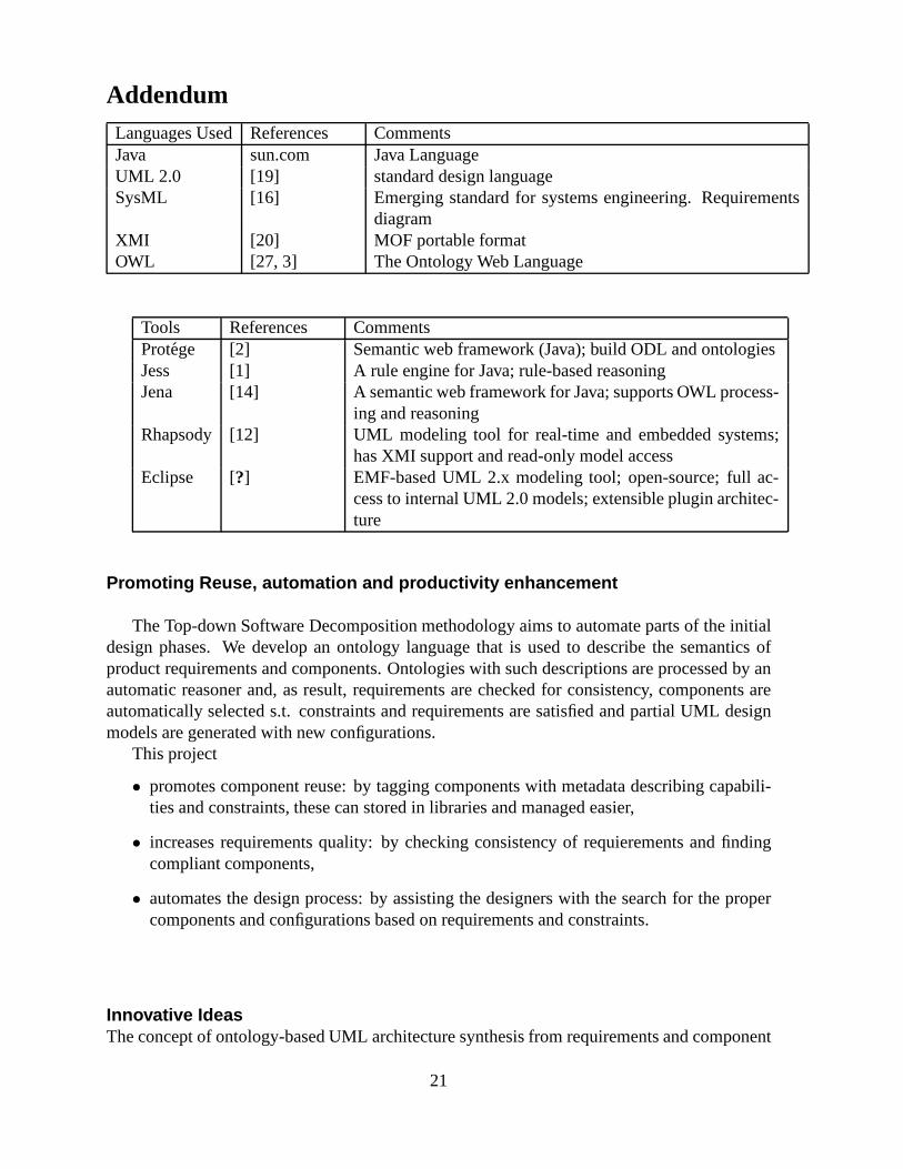
AddendumLanguages UsedReferences CommentsJava sun.com Java LanguageUML 2.0 [19] standard design languageSysML [16] Emerging standard for systems engineering. Requirements
diagramXMI [20] MOF portable formatOWL [27, 3] The Ontology Web Language
Tools References CommentsProtege [2] Semantic web framework (Java); build ODL and ontologiesJess [1] A rule engine for Java; rule-based reasoningJena [14] A semantic web framework for Java; supports OWL process-
ing and reasoningRhapsody [12] UML modeling tool for real-time and embedded systems;
has XMI support and read-only model accessEclipse [?] EMF-based UML 2.x modeling tool; open-source; full ac-
cess to internal UML 2.0 models; extensible plugin architec-ture
Promoting Reuse, automation and productivity enhancement
The Top-down Software Decomposition methodology aims to automate parts of the initialdesign phases. We develop an ontology language that is used to describe the semantics ofproduct requirements and components. Ontologies with suchdescriptions are processed by anautomatic reasoner and, as result, requirements are checked for consistency, components areautomatically selected s.t. constraints and requirementsare satisfied and partial UML designmodels are generated with new configurations.
This project
• promotes component reuse: by tagging components with metadata describing capabili-ties and constraints, these can stored in libraries and managed easier,
• increases requirements quality: by checking consistency of requierements and findingcompliant components,
• automates the design process: by assisting the designers with the search for the propercomponents and configurations based on requirements and constraints.
Innovative IdeasThe concept of ontology-based UML architecture synthesis from requirements and component
21
specifications may be original, although the related concept of bottom-up semantic servicecomposition has been applied in sensor networks and for web services. The underlying mech-anism is backward-chaining, a technique that has beed used for theorem proving.
The OPP vision for a 24 day design cycle requires integratingthe top-down decompo-sition methodology with the design toolset. Eventually, the technologies described in thiswhitepaper will have to be integrated with requirements management and MDA PIM designwith UML/SysML.
IssuesMajor issues are related to the size of the design space: (1) the complexity of the MOF andUML metaschemata, (2) the huge scope of the problem domain, (3) the big variety of sw/hwcomponents. Defining ontologies to cover all these aspects is a daunting task by itself. This isbeyond the scope of this project. To mitigate the design space problem we will focus on provingthe top-down decomposition methodology on a small application. With enough effort and bycollaborating with standardization bodies, component creators and modeling tool producersit is definitely possible to build a streamlined top-down decomposition design flow into theOPP design process, generic enough and extensible to accomodate existing and upcomingapplications with small effort.
Another issue is requirements specification. Current approached for requirements spec-ifications do not address application semantics in a formal fashion. The ODL language wepropose would permit specification of product functional requirements and QoS constraints.However, it is not feasible to ask non-technical people to design specs in the highly-specializedODL OWL-based language. A solution is to develop one of: (a) adomain-specific require-ments (visual) modeling tool that generates ODL from user-specified models, (b) mechanismsfor compiling ODL ontologies from requirements expressed in UML/SysML models. Thesecond approach may still need editing ODL for semantics notcovered by UML/SysML.
Project RoadmapThis is the current schedule, as of July 2006. It may change following August discussions withMotorola and task re-prioritization.
1. ODL ontology language prototype for a subset of UML and narrow application/componentdomain: Sept. 2006
2. ODL compilation from component UML models : Nov. 2006
3. requirements checking, component selection: Mar. 2007
4. UML structure diagram synthesis, model configurations: June 2007
5. methodology demo for a location-based services application: Fall 2007
22