Embed Size (px)
Citation preview

20. TOOLS
Basic element for a reliable connection is besides the quality
of the connector the right choice of the assembly tool.
HARTING offers the corresponding tools to all connectors.
On the following catalogue pages you find information about
tools for crimp, press-in and IDC termination. There are tools
available for different levels of automation. The choice varies
from pure hand tools for small series or service up to fully
automatic assembly tools for high volume series production.
2001
Tool
ing
20. TOOLS
CONTENTS PAGE
Tools for crimp contacts 20.02
Tools for press-in contacts 20.12
Tools for insulation displacement contacts 20.27
Tools for FOC contacts 20.31

. . 0012
. . 0004
. . 0052
2002
HARTING crimping toolwith locatorfor Han D®, Han E®, Han® C Wire gauge
09 99 000 0110 0.14 - 1.5 mm2
HARTING-Service crimping tool
with locator Wire gaugefor Han D®, Han E® 09 99 000 0021 0.14 - 1.5 mm2
Tools for crimp contacts
Identification Part No. Drawing Dimensions in mm
BUCHANAN- Wire gaugecrimping tool 09 99 000 0001 0.14 - 2.5 mm2
Locator 09 99 000 0311
Multiple crimping tool depth 09 99 000 0379 0.14 + 0.25 mm2 ø 1.001)
adjustment gauge 0.37 mm2 ø 1.300.5-1 + 2.5 mm2 ø 1.551.5 mm2 ø 1.80 order separately
HARTING-pneumatic crimping tool 09 99 000 0314
Locator 09 99 000 0311
Multiple crimping tool depth Wire gaugeadjustment gauge 09 99 000 0379 0.37 mm2 ø 1.30
0.5-1 + 2.5 mm2 ø 1.551.5 mm2 ø 1.80
Table fixing and foot switch order separatelyfor pneumatic crimping tool 09 99 000 0309
Insertion toolfor crimp contacts 09 99 000 0059
Removal toolfor crimp contacts
Removal tool 09 99 000 0012
Replacement-tip for removal tool 09 99 000 0004
Removal tool 09 99 000 0052
For crimp contacts with wires of less than 0.75 mm2 it is recom-mended that an insertion tool is used. Contacts should be inserted from the wiring side and pushed down until a positive locking is achieved.
A removal tool is necessary if contacts are to be replaced in the insert. It is inserted from the mating face and pushed over the contact until a stop is noticeable. Additional pressure unlocks the contact and pushes it out of the wiring side. In case of the removal tool (. . 0052) the unlocking process is achieved by pressure on the central rod.
Stock items in bold type1) For wire gauge 0.14 and 0.25 mm² use only male contact 09 15 000 6107 or female contact 09 15 000 6207.
Tool
ing
Tools for contacts Han D® (09 15 . . .)

2003
HARTING crimping toolwith locatorfor Han D®, Han E®, Han® C Wire gauge
09 99 000 0110 0.5 - 4 mm2
HARTING-Service crimping tool
with locator Wire gauge09 99 000 0021 0.5 - 2.5 mm2
Tools for crimp contacts
Identification Part No. Drawing Dimensions in mm
BUCHANAN- Wire gaugecrimping tool 09 99 000 0001 0.14 - 4 mm2
Locator 09 99 000 0310
Multiple crimping tool depth Wire gaugeadjustment gauge 09 99 000 0379 0.14 - 0.37 mm2 ø 1.00
0.5 - 1 mm2 ø 1.55 order separately1.5 - 2.5 mm2 ø 1.803 - 4 mm2 ø 2.00
HARTING-pneumatic crimping tool 09 99 000 0314
Locator 09 99 000 0310
Multiple crimping tool depth Wire gaugeadjustment gauge 09 99 000 0379 0.14 - 0.37 mm2 ø 1.00
0.5 - 1 mm2 ø 1.551.5 - 2.5 mm2 ø 1.80 order separately3 - 4 mm2 ø 2.00
Table fixing and foot switch for pneumatic crimping tool 09 99 000 0309
Insertion toolfor crimp contacts 09 99 000 0059
Crimp contact removalfor Han® EE, Han® Q 5/0, Han® Q 8/0Han E® and Han A® 09 99 000 0319
Removal toolfor Han® ES inserts 09 99 000 0367
A removal tool is necessary if contacts are to be replaced in the insert. The tool is inserted from the wiring side until a stop is noticeable. The wire with the crimp contact can then be pulled out from the same side of the insert.
For crimp contacts wires of less than 0.75 mm2 it is recommended that an insertion tool is used. Contacts should be inserted from the wiring side and pushed down until a positive locking is achieved.
Stock items in bold type
Tool
ing
Tools for contacts Han E® (09 33 . . .)
2004
Tools for crimp contacts
Identification Part No. Drawing Dimensions in mm
Stock items in bold type
BUCHANAN-crimping tool Wire gauge
09 99 000 0001 1.5 - 4 mm2
Locator 09 99 000 0308
Multiple crimping tool depth Wire gaugeadjustment gauge 09 99 000 0379 1.5 + 2.5 mm2 ø 1.80
4 mm2 ø 2.00 order separately
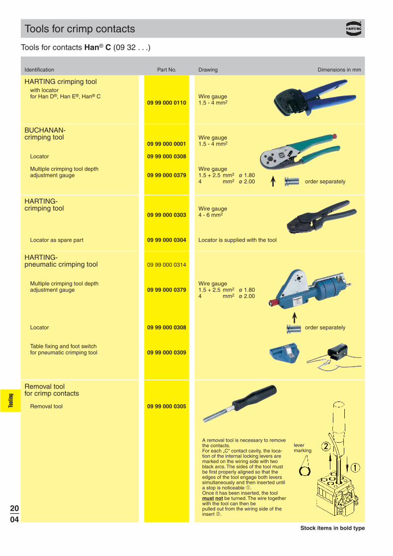
HARTING-crimping tool Wire gauge
09 99 000 0303 4 - 6 mm2
Locator as spare part 09 99 000 0304 Locator is supplied with the tool
HARTING-pneumatic crimping tool 09 99 000 0314
Multiple crimping tool depth Wire gaugeadjustment gauge 09 99 000 0379 1.5 + 2.5 mm2 ø 1.80
4 mm2 ø 2.00
Locator 09 99 000 0308 order separately
Table fixing and foot switchfor pneumatic crimping tool 09 99 000 0309
Removal toolfor crimp contacts
Removal tool 09 99 000 0305
A removal tool is necessary to remove the contacts.For each „C“ contact cavity, the loca-tion of the internal locking levers are marked on the wiring side with two black arcs. The sides of the tool must be first properly aligned so that the edges of the tool engage both levers simultaneously and then inserted until a stop is noticeable .Once it has been inserted, the tool must not be turned. The wire together with the tool can then bepulled out from the wiring side of the insert .
levermarking
HARTING crimping toolwith locatorfor Han D®, Han E®, Han® C Wire gauge
09 99 000 0110 1.5 - 4 mm2
Tool
ing
Tools for contacts Han® C (09 32 . . .)

2005
Crimping machine TK stripping and crimping in one operation(without interchangeable unit) 09 98 000 6000
interchangeable units for Han D® 09 98 000 6001Han E® 09 98 000 6002Other On request
Tools for crimp contacts
Identification Part No.
Stock items in bold type
Tool
ing
Crimping machines
Crimping machine TC-C01for pre-stripped wires
for Han D® 09 98 000 9001Han E® 09 98 000 9002Han® C 09 98 000 9003Other On request
Further details see www.HARTING.com or on request

09 99 000 0175
09 99 000 0169
09 99 000 0246
09 99 000 0253
09 99 000 0252
09 99 000 024909 99 000 025009 99 000 0251
09 99 000 0628
09 99 000 0158
09 99 000 0596
09 99 000 0597
09 99 000 0171
09 99 000 0513
2006
Tool
Identification Part No.
Tools for crimp termination – D-Sub-S, D-Sub-HD, DIN 41612
Service crimp tool
for single D-Substandard contacts
for single D-Subhigh density contacts
Assembly of crimp contactsAfter crimping the stranded wire to the contact using a hand tool or automatic crimping device, insert the contact into the chamber with the tool, working from the wiring side. You will hear the contacts snap home and to check that they are securely in place, give the wire a gentle pull.
Removing crimp contactsPosition the tool from the wiring side as shown in the diagram below and insert into the contact chamber. The contact can then easily be removed from the wiring side together with the wire itself and reinserted in a different chamber. The tool is designed for a maximum insulation diameter of Ø 1.7 mm.
Stripping length: 2.5 + 0.5 mm
for 500 bandoliered D-Sub standard contacts
for 500 bandoliered D-Sub high density contacts
HARTING-Crimp tool
HARTING-Semi-automaticcrimping device
Main drivefoot-operated220 V / 50 Hz
Crimping head forbandoliered D-Sub standard contacts
for DIN 41612contacts, types
BC
FC 1FC 2FC 3
BC solid wire
Reel holder for10 000 contacts
Insertion andremoval tool
for single D-Substandard contacts
for single D-Subhigh density contacts
Wire gauge
0.09-0.56 mm2 (AWG 28-20)
0.09 - 0.5 mm²
0.09 - 0.25 mm²0.14 - 0.56 mm²0.5 - 1.5 mm²
0.13 mm² (solid wire)
Tool
ing
Tools for crimp contacts

2007
Part No. 09 98 000 5000
Technical characteristics
DimensionsHeight 690 mm
(1400 mm with a contact reel)Width 350 mmDepth 370 mm
Total weight 72 kg
Power supply 230 V, 50/60 Hz, 2.5 A
Consumption 0.75 kW
Motor speed 440 - 2000 rpm
Cable length 2 m incl. plug
Control SPS
Work cycle trigger Sensor
Work cycle 0.35 s for stripping and crimping
Illumination Integrated tool light
Stroke counter Daywise and fixed
Crimp force monitor BB07i
Crimping tool Quick change tool
Adjustable Crimping heigth on wireprocess Crimping heigth on insulationparameters Depth of insulation stripping
Length of insulation strippingWire retainer positionWire position in the crimp contactBand thrust
Automated crimping machine type BK
Main characteristics
Smooth run through electronic brakes
Hand wheel for manual adjustments
Maintenance friendly through needle bearing rail
Simple handling by quick change tool and stripper
Further details you will find in our product flyer.1) 2.5 + 0.5 mm of insulation is stripped from the wire to be crimped
Tool
ing
Tools for crimp contacts
Tools for crimp termination – D-Sub-S, D-Sub-HD, DIN 41612
for use Wire gauge InsulationIdentification with Part No. [mm²] AWG [Ø mm]
standard 09 98 000 3008 0.09 - 0.25 28 - 24 0.7 - 1.4contacts 09 98 000 3009 0.25 - 0.56 24 - 20 0.9 - 1.7
high density 09 98 000 3012 26 - 24 0.8 - 1.4contacts
Crimping tool
for D-Sub connectors1)

09 99 000 0501
61 03 600 002361 03 600 0024
61 03 000 0112 61 03 600 0024 7
61 03 000 0113 61 03 600 0024 7
61 03 000 0073 61 03 600 0023 7
61 03 000 0074 61 03 600 0023 7
61 03 000 0094 61 03 600 0023 7
61 03 000 0096 61 03 600 0023 7
61 03 000 0078 61 03 600 0023 7
61 03 000 0080 61 03 600 0023 7
2008
Identification Part No. Drawing
Crimp toolfor turned male and female contactsAWG 28-188 indent crimp in acc. to MIL 22 520/2-01
Locator for crimp toolDetails see table
Part No. Part No. Crimp toolcontact locator selection no.
Tool
ing
Tools for crimp contacts
Tools for crimp termination – D-Sub-S, D-Sub-HD

2009
09 99 000 0501
09 99 000 0502
09 99 000 0505
09 99 000 0509
09 99 000 0504
09 99 000 0503
09 99 000 0508
09 99 000 0515
09 99 000 0519
09 99 000 0522
09 99 000 0521
1) Only the outer ferrule is crimped (inner conductor is soldered)
Tool
ing
Identification Part No.
Tools for crimp termination
Hand crimp toolfor signal contacts
Die(To be ordered separately.) Wire gauge AWG 18 – 28
Hand crimp toolwith fixed die
for signal contacts
Wire gauge AWG 20 – 26
Hand crimp toolfor power contacts
Positioner for male and female contacts(To be ordered separately.)
Hand crimp toolfor coaxial contacts,solder/crimp version1)
Die(To be ordered separately.)
Die(To be ordered separately.)
Contact Part No. Cavity09 69 181 x23009 69 281 x230 B
09 69 181 x14109 69 281 x141 C
09 69 181 x14009 69 281 x140 B
Contact Part No. Cavity09 69 181 x14309 69 281 x143 A
Contact Part No. Gauge Tool setting09 69 182 x420 AWG 16, 18, 20 3 for AWG 16, 2 for AWG 18 and AWG 2009 69 282 x420 AWG 16, 18, 20 3 for AWG 16, 2 for AWG 18 and AWG 2009 69 182 x421 AWG 12, 14 5 for AWG 12 and 4 for AWG 1409 69 282 x421 AWG 12, 14 5 for AWG 12 and 4 for AWG 1409 69 182 x422 AWG 10, 12 7 for AWG 10 and 6 for AWG 1209 69 282 x422 AWG 10, 12 7 for AWG 10 and 6 for AWG 1209 69 182 x423 AWG 8, 10 7 for AWG 8 and 6 for AWG 1009 69 282 x423 AWG 8, 10 7 for AWG 8 and 6 for AWG 10
Die(To be ordered separately.)
Contact Part No. Cavity09 69 181 x23309 69 281 x233 B
D-Sub – M
Contact Part No. Gauge Tool setting09 69 282 x821 AWG 12, 14 5 for AWG 12 and 4 for AWG 1409 69 282 x823 AWG 8, 10 7 for AWG 8 and 6 for AWG 10
Positioner for male contacts(To be ordered separately.)
Contact Part No. Gauge Tool setting09 69 182 x821 AWG 12, 14 5 for AWG 12 and 4 for AWG 1409 69 182 x823 AWG 8, 10 7 for AWG 8 and 6 for AWG 10
Positioner for female contacts(To be ordered separately.)

09 99 000 0501
09 99 000 0507
09 99 000 0511
09 99 000 0512
09 99 000 0503
09 99 000 0508
09 99 000 0518
09 99 000 0519
2010
Identification Part No.
Hand crimp toolfor coaxial contacts,crimp/crimp version1),suitable for innercontact
Inner contact die(To be ordered separately.)
Insertion and extraction tool
for signal contacts
Extraction toolfor coaxial, powerand high voltage contacts
Hand crimp toolfor coaxial contacts,crimp/crimp version1),suitable for outerferrule
1) Both inner and outer conductor are crimped
Outer contact die(To be ordered separately.)
Outer contact die(To be ordered separately.)
Contact Part No.
09 69 182 x140
09 69 282 x140
09 69 182 x230
09 69 282 x230
09 69 182 x232
09 69 282 x232
09 69 182 x233
09 69 282 x233
Contact Part No. Cavity09 69 182 x14009 69 282 x140 B
09 69 182 x23009 69 282 x230 B
Contact Part No. Cavity09 69 182 x23209 69 282 x232 A
Outer contact die(To be ordered separately.)
Contact Part No. Cavity09 69 182 x23309 69 282 x233 B
Tool
ing
Tools for crimp contacts
Tools for crimp termination – D-Sub-M

61 03 600 0021
61 03 600 0020
61 03 600 001761 03 600 0018
09 99 000 0171
61 03 000 017961 03 000 018061 03 000 009861 03 000 009961 03 000 010061 03 000 010161 03 000 010261 03 000 010361 03 000 010461 03 000 010561 03 000 017461 03 000 017261 03 000 016861 03 000 016961 03 000 017561 03 000 017661 03 000 017761 03 000 017861 03 000 0173
2011
Identification Part No. Drawing
Hexagonal head screwdriverfor hoods with hexagonal screws
Crimp toolfor flange and ferrule
Inserts for crimp tool
for D-Sub hoods (9-37 contacts)for D-Sub hoods (50 contacts)9-
Mounting toolfor flange
Insertion and removal toolfor contacts
Width of hexagonal nut [mm]
5.0 5.5 6.0 6.5 7.0 7.5 8.0 8.5 9.0 9.510.010.511.011.512.012.513.013.514.0
Tool
ing
Tools for crimp contacts
Tools for crimp termination – InduCom
2012
Tools for press-in contacts
The HARTING modular tooling system
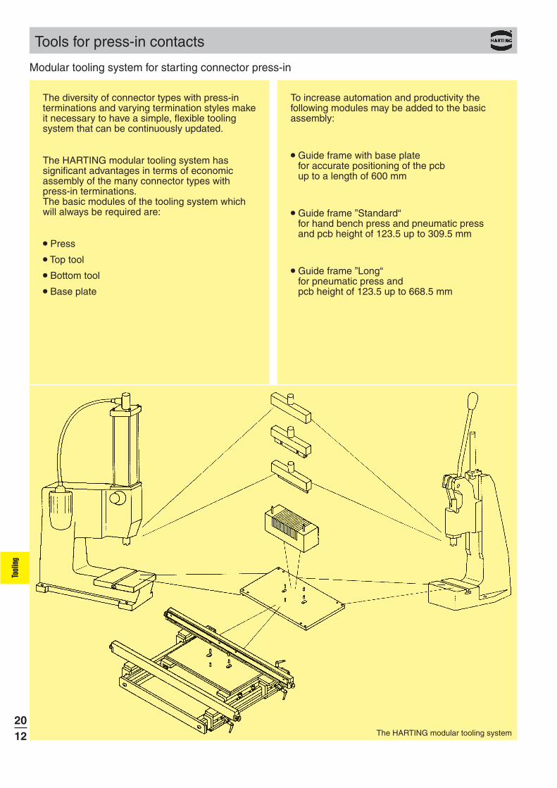
The diversity of connector types with press-in terminations and varying termination styles make it necessary to have a simple, flexible tooling system that can be continuously updated.
The HARTING modular tooling system has significant advantages in terms of economic assembly of the many connector types with press-in terminations. The basic modules of the tooling system which will always be required are:
Press
Top tool
Bottom tool
Base plate
To increase automation and productivity the following modules may be added to the basic assembly:
Guide frame with base plate for accurate positioning of the pcb up to a length of 600 mm
Guide frame ”Standard“ for hand bench press and pneumatic press and pcb height of 123.5 up to 309.5 mm
Guide frame ”Long“ for pneumatic press and pcb height of 123.5 up to 668.5 mm
Tool
ing
Modular tooling system for starting connector press-in

2013
Tools for press-in contacts
When setting up an assembly machine it is not necessary to set the working height of the press and adjust the base plate more than once. There is no need for further adjustments. All the other adaptations for various applications are performed efficiently and are reliant by various combinations of individual modules.
Positioning the bottom tool in relation to the top tool
The ram of the HARTING press is generally provided with a cross-shaped groove which accurately positions the top tool in steps of 90°.
Two guide pins position the bottom tool in relation to the top tool simply and accurately.
These guide pins cannot be used for positioning the pcb or the connector!
Two pairs of pins on the base plate locate the bottom tool in relation to the top tool in steps of 90°.
Height compensation
Various overall heights of connectors are accommodated by type-specific top tools.
Various pcb thicknesses are accommodated by the use of spacers between the bottom tool and base plate.
Ram with cross-shaped groove
Positioning the bottom tool in relation to top tool
Base plate with pairs of location pins at 90°
Tool
ing
Handling indications

2014
Tools for press-in contacts
Range of applications for the bottom tool
One bottom tool can be used to assemble connectors with straight or angled press-in terminations.
When pressing in the connectors with angled press-in terminations the positioning pins remain in the bottom tool and serve as guide pins for the connector.
By rotating the bottom tool in steps of 90° and relocating the positioning pins it is possible to assemble half-length connectors with angled press-in terminations.
Bottom tool (narrow version)
In addition to the square bottom tool with multi-functional properties, HARTING offers the alternative of a narrow bottom tool for assembling connectors with straight press-in terminations. This tool supports the pcb within the press-in connector zone and therefore makes it possible to assemble connectors where electronic components are to be placed in close proximity.
Guide frame
The guide frame screwed to the base plate ensures the correct positioning of the pcb in relation to the top and bottom tools and permits a much higher rate of assembly.
Both guide rails are adjustable to accommodate various pcb sizes.
A spring-loaded supporting rail lifts the pcb away from the bottom tool after the press-in operation ensuring that no damage occurs to the conductors as it passes through the machine.
Bottom tool set for assembling connectors with angled pins
Bottom tool set for assembling half-length connectors with angled pins
Narrow version of the bottom tool for special applications
Guide frame for positioning the pcb in relation to the top and bottom tools
Tool
ing
Handling indications

2015
16 99 000 0005 000
16 99 000 0006 000
16 99 000 0003 000
16 99 000 0004 000
16 99 000 0001 000
16 99 000 0002 000
02 99 000 0002
16 99 000 0011 000
02 99 000 0002 16 99 000 0008 000
16 99 000 0010 00016 99 000 0009 000
16 99 000 0007 000
16 99 000 0012 000
Tool
ing
Press-in tooling
Removal tool for AdvancedTCA® B+
For a reliable and safe press-in process HARTING has developed a special tooling system. Each tooling is adapted to the special requirements of the individual connector range, thus a good handling and quick adjustment is guaranteed.
Repair pliers forMicroTCA™
Removal tool for AdvancedTCA® B+
Top tool for MicroTCA™
Bottom tool for MicroTCA™
Top tool for AdvancedTCA® B+
Bottom tool for AdvancedTCA® B+
Top tool for AdvancedTCA® B+
Bottom tool for AdvancedTCA®
B+
Top tool for MicroTCA™
Bottom tool for MicroTCA™
Repair pliers for MicroTCA™
Top tool for AdvancedTCA® Power
Male and female connector
Top tool for AdvancedTCA®
Power and MicroTCA™ Power,module version
Bottom tool for AdvancedTCA® Power
Male and female connector
Top tool for MicroTCA™ Power
Module versionBackplane version
Bottom tool for MicroTCA™ Power
Module versionBackplane version
Bottom tool for AdvancedTCA®
Power
Top tool for MicroTCA™Power,backplane version
Bottom tool for MicroTCA™Power,backplane version
Bottom tool for MicroTCA™Power,module version
Identification Part No. Drawing
Removal tool for MicroTCA™
Removal tool for MicroTCA™
Removal tool for MCH Plug stacking-pins
Removal tool forMCH Plug stacking-pins

2016
Tools for press-in contacts
For economical and safe press-in of connectors with 5+2 and 8+2 rows,
HARTING has developed a discrete tooling system.
Due to its modular structure it can be adapted to any connector configuration that needs to be pressed-in extremely quickly and securely.
Therefore a top and a bottom tool for each connector style is available. These tools are inserted in a top or bottom carrier tool with a groove, thus guaranteeing exact position of the top and bottom tools and the connectors.
To use identical carrier tools for all connector configurations, HARTING offer spacer blocks to fill gaps between adjacent top or bottom tools.
The carrier tool is either completely filled with top or bottom tools or respective spacer blocks, making it possible to press-in single modules.
To press-in female connectors with pre-installed upper shields, separate top and bottom tools are available.
For lower shield press-in the tooling can be changed easily.
For further information please check our operating instructions or contact your HARTING representative.
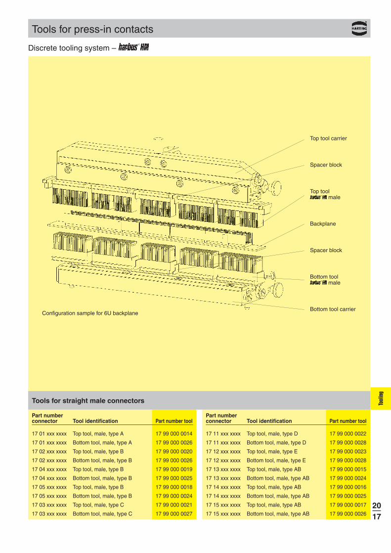
Top tool carrier
Spacer block
Spacer block
Bottom tool carrier
Part number connector Tool identification Part number tool
17 xx xxx xxxx Top tool carrier 17 99 000 0012
17 xx xxx xxxx Bottom tool carrier 17 99 000 0013
17 xx xxx xxxx Top tool carrier 3U 17 99 000 0073
17 xx xxx xxxx Bottom tool carrier 3U 17 99 000 0074
17 xx xxx xxxx Spacer block 0.67 mm 17 99 000 0057(CompactPCI)
17 xx xxx xxxx Spacer block 5 mm 17 99 000 0056
Part number connector Tool identification Part number tool
17 xx xxx xxxx Spacer block 25 mm 17 99 000 0055
17 xx xxx xxxx Spacer block 38 mm 17 99 000 0054
17 xx xxx xxxx Spacer block 44 mm 17 99 000 0053
17 xx xxx xxxx Spacer block 50 mm 17 99 000 0052
17 xx xxx xxxx Centering plate female left 17 99 000 0060
17 xx xxx xxxx Centering plate female right 17 99 000 0061
Basis tools for all connector types
Basis tools of the discrete tooling system
Tool
ing
Discrete tooling system –
2017
Part number connector Tool identification Part number tool
17 01 xxx xxxx Top tool, male, type A 17 99 000 0014
17 01 xxx xxxx Bottom tool, male, type A 17 99 000 0026
17 02 xxx xxxx Top tool, male, type B 17 99 000 0020
17 02 xxx xxxx Bottom tool, male, type B 17 99 000 0026
17 04 xxx xxxx Top tool, male, type B 17 99 000 0019
17 04 xxx xxxx Bottom tool, male, type B 17 99 000 0025
17 05 xxx xxxx Top tool, male, type B 17 99 000 0018
17 05 xxx xxxx Bottom tool, male, type B 17 99 000 0024
17 03 xxx xxxx Top tool, male, type C 17 99 000 0021
17 03 xxx xxxx Bottom tool, male, type C 17 99 000 0027
Part number connector Tool identification Part number tool
17 11 xxx xxxx Top tool, male, type D 17 99 000 0022
17 11 xxx xxxx Bottom tool, male, type D 17 99 000 0028
17 12 xxx xxxx Top tool, male, type E 17 99 000 0023
17 12 xxx xxxx Bottom tool, male, type E 17 99 000 0028
17 13 xxx xxxx Top tool, male, type AB 17 99 000 0015
17 13 xxx xxxx Bottom tool, male, type AB 17 99 000 0024
17 14 xxx xxxx Top tool, male, type AB 17 99 000 0016
17 14 xxx xxxx Bottom tool, male, type AB 17 99 000 0025
17 15 xxx xxxx Top tool, male, type AB 17 99 000 0017
17 15 xxx xxxx Bottom tool, male, type AB 17 99 000 0026
Tools for straight male connectors
Top tool carrier
Spacer block
Top tool male
Backplane
Spacer block
Bottom tool male
Bottom tool carrierConfiguration sample for 6U backplane
Tool
ing
Tools for press-in contacts
Discrete tooling system –

2018
Configuration sample for a 6U daughtercard
Top tool carrier
Spacer block
Centering plate
Top tool female
Daughtercard
Spacer block
Bottom tool female
Bottom tool carrier
Part number connector Tool identification Part number tool
17 21 xxx xxxx Top tool, female, type A 17 99 000 002917 21 xxx xxxx Bottom tool, female, type A 17 99 000 004617 22 xxx xxxx Top tool, female, type B 17 99 000 003817 22 xxx xxxx Bottom tool, female, type B 17 99 000 004617 24 xxx xxxx Top tool, female, type B 17 99 000 003617 24 xxx xxxx Bottom tool, female, type B 17 99 000 004517 25 xxx xxxx Top tool, female, type B 17 99 000 003417 25 xxx xxxx Bottom tool, female, type B 17 99 000 004417 23 xxx xxxx Top tool, female, type C 17 99 000 004017 23 xxx xxxx Bottom tool, female, type C 17 99 000 0047
Part number connector Tool identification Part number tool
17 31 xxx xxxx Top tool, female, type D 17 99 000 004217 31 xxx xxxx Bottom tool, female, type D 17 99 000 004817 32 xxx xxxx Top tool, female, type E 17 99 000 004217 32 xxx xxxx Bottom tool, female, type E 17 99 000 004817 33 xxx xxxx Top tool, female, type AB 17 99 000 003217 33 xxx xxxx Bottom tool, female, type AB 17 99 000 004417 34 xxx xxxx Top tool, female, type AB 17 99 000 005817 34 xxx xxxx Bottom tool, female, type AB 17 99 000 004517 35 xxx xxxx Top tool, female, type AB 17 99 000 002917 35 xxx xxxx Bottom tool, female, type AB 17 99 000 0046
Tools for angled female connectors
Part number connector Tool identification Part number tool
17 21 xxx xxxx Top tool, female, 17 99 000 0030type A upper shield
17 21 xxx xxxx Top tool, female, type A divided 17 99 000 0031shield computer telephony
17 22 xxx xxxx Top tool, female, 17 99 000 0039type B upper shield
17 24 xxx xxxx Top tool, female, 17 99 000 0037type B upper shield
17 25 xxx xxxx Top tool, female, 17 99 000 0035type B upper shield
17 23 xxx xxxx Top tool, female, 17 99 000 0041type C upper shield
17 31 xxx xxxx Top tool, female, 17 99 000 0043type D upper shield
17 32 xxx xxxx Top tool, female, 17 99 000 0043type E upper shield
17 33 xxx xxxx Top tool, female, 17 99 000 0033type AB upper shield
Part number connector Tool identification Part number tool
17 34 xxx xxxx Top tool, female, 17 99 000 0059type AB upper shield
17 35 xxx xxxx Top tool, female, 17 99 000 0030type AB upper shield
17 21 xxx xxxx Press-in die lower shield type A 17 99 000 0051
17 22 xxx xxxx Press-in die lower shield type B 17 99 000 0051
17 24 xxx xxxx Press-in die lower shield type B 17 99 000 0050
17 25 xxx xxxx Press-in die lower shield type B 17 99 000 0049
17 31 xxx xxxx Press-in die lower shield type D 17 99 000 0051
17 32 xxx xxxx Press-in die lower shield type E 17 99 000 0051
17 33 xxx xxxx Press-in die lower shield 17 99 000 0049type AB
17 34 xxx xxxx Press-in die lower shield 17 99 000 0050type AB
17 35 xxx xxxx Press-in die lower shield 17 99 000 0051type AB
Tools for angled shielded female connectors
Tool
ing
Tools for press-in contacts
Discrete tooling system –

ÀÁ
Â
2019
Tools for press-in contacts
For 6U backplanes with CompactPCI configuration, HARTING has developed this start-up tooling.
The basis is a top tool carrier with tooth inserts, that are engaged alternately.
Therefore this tooling assembly can be used without any additional set-up time.
The tooth inserts are interchangeable, so that the tooling can be used for other connector configurations as well as for CompactPCI.
The bottom tool should preferably be a loadnest, which carries and aligns the pcb.
For detailed information please contact your local HARTING representative.
Tool Part number identification tool
À Insert top tool 17 99 000 0063for 6U CompactPCI
Á Insert top tool 17 99 000 0065for 3U CompactPCI
 Insert top tool on requestfor rotatable tool changer
Tool Part number identification tool
Tooth insert 17 99 000 0066for type Monoblock 47
Tooth insert 17 99 000 0068for type B19 positions
Tools for straight male connectors
Changeableinsert
Loadnest
Pcb
Configuration samples for CompactPCI backplanes
Tooth sheetmetal
Tool
ing
Tooling for backplanes –

2020
Part number connector Tool identification Quantity and part number tool
17 01 xxx xxxx Insert block for type A 1 x 17 99 000 0009 or (2 x 17 99 000 0001)
17 04 xxx xxxx Insert block for type B 1 x 17 99 000 0004
17 05 xxx xxxx Insert block for type B 1 x 17 99 000 0002
17 02 xxx xxxx Insert block for type B 1 x 17 99 000 0003
17 03 xxx xxxx Insert block for type C 1 x 17 99 000 0001
17 06 xxx xxxx Insert block for type Monoblock 47 1 x 17 99 000 0008 or (1 x 17 99 000 0001 and 1 x 17 99 000 0005)
17 11 xxx xxxx Insert block for type D 2 x 17 99 000 0006
17 12 xxx xxxx Insert block for type E 1 x 17 99 000 0007
17 13 xxx xxxx Insert block for type AB 1 x 17 99 000 0069
17 14 xxx xxxx Insert block for type AB 1 x 17 99 000 0070
17 15 xxx xxxx Insert block for type AB 1 x 17 99 000 0071
17 10 xxx xxxx Insert block for type DE 1 x 17 99 000 0072
Insert blocks for straight male connectors
Part number connector Tool identification Part number tool
17 xx xxx xxxx Flat rock die for 6U 07 79 000 0155
17 xx xxx xxxx Flat rock die for 3U 07 79 000 0156
Flat rock dies
Tools for press-in contacts
The insert blocks can be used to press-in male connectors without any special top
tool. These blocks will be put into the connectors manually or automatically.
To press-in the connector no precise position is needed and can be done by a simple flat rock die. This will accelerate the cycle time of the press-in process dramatically.Insert blocks are developed for use with a loadnest.
The insert block 17 99 000 0001 e.g. can be used for the types A, C and Monoblock 47.
Flat rock die
Insert block
Pcb
LoadnestApplication samples for insert blocks
Tool
ing
Insert blocks for male connectors –
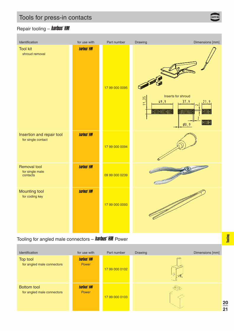
17 99 000 0095
17 99 000 0094
17 99 000 0093
17 99 000 0102
17 99 000 0103
09 99 000 0239
Power
Power
2021
Tools for press-in contacts
Tool kitshroud removal
Insertion and repair toolfor single contact
Mounting toolfor coding key
Identification for use with Part number Drawing Dimensions [mm]
Top toolfor angled male connectors
Identification for use with Part number Drawing Dimensions [mm]
Bottom toolfor angled male connectors
Removal toolfor single malecontacts
Inserts for shroud
Tool
ing
Repair tooling –
Tooling for angled male connectors – Power

2022
Tools for press-in contacts
Straight Mini Coax connectors can be pressed-in with a flat die and a top tool delivered with the connectors. This top tool can be used as contact protection and remains in the connector until the daughtercard is mated.
Angled Mini Coax connectors will be pressed-in with separate top and bottom tools, which will be mounted into a common body.
Body
Top tool
Bottom tool
Configuration for angled modules
Part number Part number connector Tool identification tool
07 11 xxx xxxx 1 SU Mini Coax Standard on requestbottom tool
07 11 xxx xxxx 1.25 SU Mini Coax Standard on requestbottom tool
07 11 xxx xxxx 1.50 SU Mini Coax Standard on requestbottom tool
Tools for straight modules
Part number Part number connector Tool identification tool
07 31 xxx xxxx Body 07 79 000 0061
07 31 xxx xxxx 1 SU Mini Coax Standard 07 79 000 0045bottom tool
07 31 xxx xxxx 1 SU Mini Coax Standard 07 79 000 0080top tool
07 31 xxx xxxx 1.25 SU Mini Coax Standard 07 79 000 0034bottom tool
07 31 xxx xxxx 1.25 SU Mini Coax Standard 07 79 000 0081top tool
07 31 xxx xxxx 1.50 SU Mini Coax Standard 07 79 000 0171bottom tool
07 31 xxx xxxx 1.50 SU Mini Coax Standard 07 79 000 0170top tool
07 31 xxx xxxx 1 SU Mini Coax single-row 07 79 000 0205bottom tool
07 31 xxx xxxx 1 SU Mini Coax single-row 07 79 000 0204top tool
Tools for angled modules
Tool
ing
Discrete tooling system – Mini Coax

09 99 000 0201
09 99 000 0282
09 99 000 0279
09 99 000 0244
09 99 000 0261
09 99 000 0255
2023
Tools for press-in contacts
Identification Part No. Drawing Dimensions in mm
Hand bench press
Technical characteristicsWorking stroke 25 mmPress force 15 kN max.Hole ø in the ram ø 10 mmNet weight approx.
23 kg
Pneumaticpress
40 kN
Adaptor for height compensation1)
base plate
Guide frame withbase plate
Standard typefor pcb sizex = 123,5 - 309,5 mm
Long type2)
for pcb sizex = 123,5 - 668,5 mm
Base plate
1) suitable for 09 99 000 0282 and all CPM machines2) not suitable for hand bench press
Technical characteristicsTotal stroke 48 mmWorking stroke 0-6 mmPress force 40 kN max.Air pressure 6 barHole ø in the ram ø 10.01 mmNet weight 136 kgPower supply 110 V / 220 V AC
Tool
ing
Hand bench presses / pneumatic presses

CPM prestige
2024
Tools for press-in contacts
Built-in features: Guiding rails (carbon/spring-loaded) for the secure positioning of the pcbTouch-screen and Industrial PC with UPS (uninterruptable power supply)Barcode reader for management ease of press-in programsAll dimensions allow an easy integration into production lines
Process monitoring and quality assurance: Touch screen interface with graphical and verbal menus for all machine functions
Autosense: automated press-in interruption at incorrect press-in forcesStorage and validation of all press-in parameters via quality assurance software (press-in force tolerances)Continuous high-precision measurement and recording of press-in forces and distancesRemote determination of errors and maintenanceHigh flexibility through a modular tool range
Options: Rotatable tool changer Insertion removal station
Part No. 09 89 040 0000
Technical characteristics
Drive electro-mechanical, servoPress-in force 100 kNmax. pcb dimensions 600 x 1000 mmFloor space 1200 x 1150 mmWeight 980 kgPower supply 3x 208 / 380 / 400 / 415 VConsumption < 1 kWColour on request
CPM prestige(incl. PC, control software, barcode reader, keyboard, touch screen)
Insertion removal station Power supply 220 V / 50 Hz
Air pressure 6 bar (15-16 l/min.)
Part No. 09 89 040 3000
for pcb dimensionsof max.710 mm x 540 mm
Bestseller CPM prestige with insertion removal station,adaptable to all HARTING press-in machines.
Tool
ing
CPM press-in machines

60 99 000 0032
09 99 000 060009 99 000 0523
09 99 600 070909 99 600 071509 99 600 0725
60 99 000 0031
09 99 000 0197
09 99 000 0255
2025
Identification Part No.
Press-out toolfor har-mik
Bottom tool
Bottom toolnarrow for D-Sub
Only one tool for all polarities, with or without grounding pins
Plastic with metal plate insert tool
for D-Sub male
Tools – SEK, D-Sub, har-mik
Bottom toolfor har-mik
Other toolings on request
9 way15 way25 way
9-37 way50 way
Top tool for SEK
Base plate for SEK, D-Sub, har-mik
Top tool
Bottom tool
Base plate
Tool
ing
Tools for press-in contacts

09 99 000 0 0609 99 000 0 1009 99 000 0 1409 99 000 0 1609 99 000 0 2009 99 000 0 2609 99 000 0 3409 99 000 0 4009 99 000 0 5009 99 000 0 6009 99 000 0 64
09 99 000 0220
09 99 000 0218
09 99 000 071009 99 000 071409 99 000 071609 99 000 072009 99 000 072609 99 000 073409 99 000 074009 99 000 075009 99 000 076009 99 000 0764
2026
Identification Part No. Drawing Dimensions in mm
Top toolincluding insert 4Modular insert 5
6 way10 way14 way16 way20 way26 way34 way40 way50 way60 way64 way
Top toolfor SEK male low-profile connectors
Top tool including insert
Modular insert
Press-out toolfor complete SEKmale connectors with5.5 mm terminations
Support block
X Length depends on number of contacts
* Further versions on request
10 way14 way16 way20 way26 way34 way40 way50 way60 way64 way
Top toolfor SEK standard connectors
X Length depends on number of contacts
Tool
ing
Tools – SEK, D-Sub, har-mik
Tools for press-in contacts

CAT 60
60 99 000 0003
60 99 000 0004
60 99 000 0012
60 99 . . . 0005
60 99 . . . 0013
27 79 000 0001
27 79 000 0002
27 99 000 0001
60 99 000 0007
2027
Cable aligner for har-link
Head and table for har-link
Crimping hand tool for har-link
Hand press for har-link
Tools for insulation displacement termination – har-link, har-mik
Identification Part No.
Semi-automatic machineCAT 60 for har-mik
Number of contacts
Support plates
Adaptator
Support platesfor har-mik Pin and socket and female Bellows connector
Support platesfor har-mik male Bellows connector
Adaptorfor har-mik male Pin and socket connector
Adaptorfor har-mik male Bellows connector
Tool
ing
Tools for insulation displacement contacts
Table
Head
A manual for the har-link® cable free connectorassembly is available in our online catalogue HARKIS ® or on demand at your local HARTING representative
AaHr
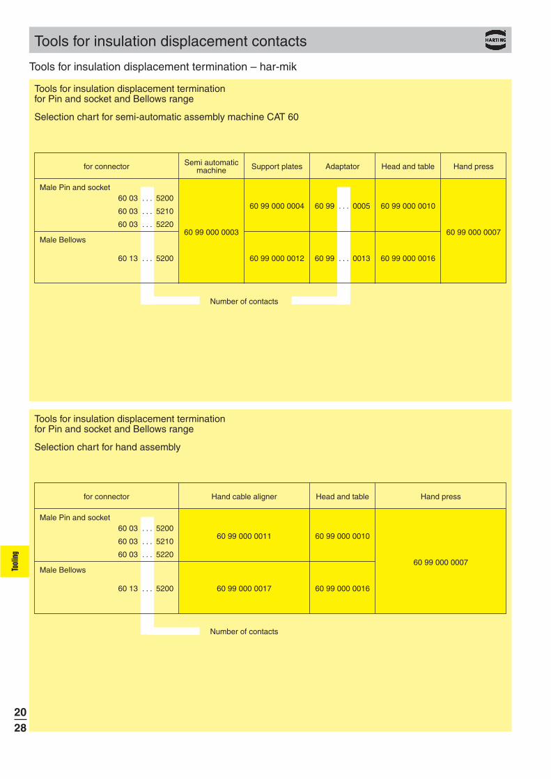
60 99 000 0003
60 99 000 0004
60 99 000 0012
60 99 000 0010
60 99 000 0016
60 99 000 0007
60 03 . . . 5200
60 03 . . . 5210
60 03 . . . 5220
60 13 . . . 5200
60 99 . . . 0005
60 99 . . . 0013
60 99 000 0011
60 99 000 0017
60 99 000 0007
60 03 . . . 5200
60 03 . . . 5210
60 03 . . . 5220
60 13 . . . 5200
60 99 000 0010
60 99 000 0016
2028
Tools for insulation displacement terminationfor Pin and socket and Bellows range
Selection chart for semi-automatic assembly machine CAT 60
Semi automaticfor connector machine Support plates Adaptator Head and table Hand press
Male Pin and socket
Male Bellows
Number of contacts
Tools for insulation displacement terminationfor Pin and socket and Bellows range
Selection chart for hand assembly
for connector Hand cable aligner Head and table Hand press
Male Pin and socket
Male Bellows
Number of contacts
Tool
ing
Tools for insulation displacement termination – har-mik
Tools for insulation displacement contacts

2029
60 99 000 0007
60 99 000 0010
60 99 000 0016
60 99 000 0011
60 99 000 0017 Tool
ing
Tools for insulation displacement termination – har-mik
Tools for insulation displacement contacts
Identification Part No.
Hand press
Head and table for male Pin and socket connector
Head and table for male Bellows connector
Hand cable aligner for Pin and socket and
female Bellows connector
Hand cable aligner for male Bellows connector
Hand press
Table
Head
A manual for the har-mik® connector and cable assembly is available in our online catalogue HARKIS ® or on demand at your local HARTING representative.

09 99 000 0114
09 99 000 013509 99 000 011509 99 000 013409 99 000 013109 99 000 013009 99 000 0150
09 99 600 0201
09 99 000 0149
09 99 000 0116
09 99 000 017909 99 000 0180
60 99 000 0034
2030
Identification Part No. Drawing Dimensions in mm
Tool
ing
Tools for insulation displacement termination – D-Sub, har-mik, SEK
Tools for insulation displacement contacts
Bench pressfor termination of insulation displacement connectors
suitable for D-Subhar-mikSEK
Hand tool with base plates(included in tool kit)
for termination of insulationdisplacement connectors
suitable for D-SubSEK
Cable cutterfor flat cables
suitable for D-Subhar-mikSEK
Base platefor termination of flat cablessuitable for D-Sub
SEK femaleSEK DIPSEK LP, 2 rowsSEK LP, 4 rowsDIN 41612
Insertfor terminationof 37 pole male D-Sub connectors
Spare partsBladeCutting plate
Base platefor termination of flat cablessuitable for har-mik

DIN 41 626 20 99 000 1092
20 99 000 1035
20 99 000 1031
20 99 000 1033
20 80 001 9902
2031
POF2) cable Ø 2.2 20 99 000 1093
Polishing tool
Fibre stripper
20 99 000 1041 0.3 mm20 99 000 1045 1 mm20 99 000 1046 0.18/0.3 mm
Crimping toolfor 1 mm POF contacts
– Han D®, Han E®
– DIN 41 626– Ferrule– F-SMA, -ST
for crimping the strain relief to the connector… 1031 FO cable for glass fibre… 1033 POF2) and SERCOS cable Ø 6.0 and 3.6
2 ml EPO-TEK 360 with hardener (10:1), 4 g foil pack
Delivery range:Each part number ordered comprises 2 pieces
HARTING Crimping toolfor FO connector(glass fibre)SW 4.3 mm
3.8 mm4.95 mm
HARTING Crimping toolfor FO connector(plastic fibre)SW 6.95, 4.95 and 3.0 mm
Epoxy adhesiveglass fibre
Polishing paperfor POF2)-grain size 1000 20 80 001 9911for GI 9 μ-grain size 20 80 001 9912for GI 1 μ-grain size 20 80 001 9913
Tools for FOC contacts
Identification Part No. Drawing Dimensions in mm
2) POF = Polymer optical fibre Stock items in bold type
Tool
ing
Tools for FOC contacts