Embed Size (px)
Citation preview
B111A
SPX
NEW
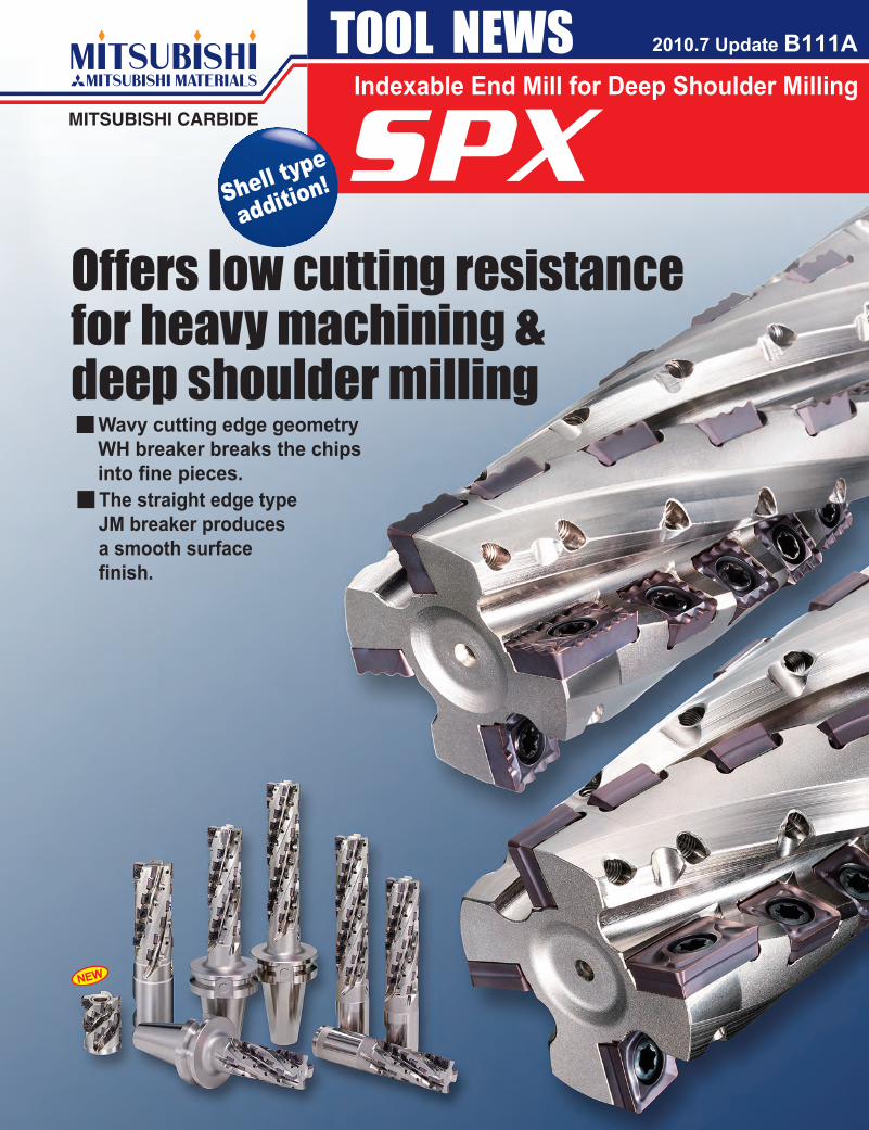
Indexable End Mill for Deep Shoulder Milling2010.7 Update
Shell type
addition!
Offers low cutting resistance for heavy machining & deep shoulder millingy Wavy cutting edge geometry
WH breaker breaks the chips into fine pieces.
y The straight edge type JM breaker produces a smooth surface finish.
1
SPXa
a
0
112
225
337
450
562
674SPX
SPX
y
y
Indexable End Mill for Deep Shoulder Milling
Features
Cutting performance
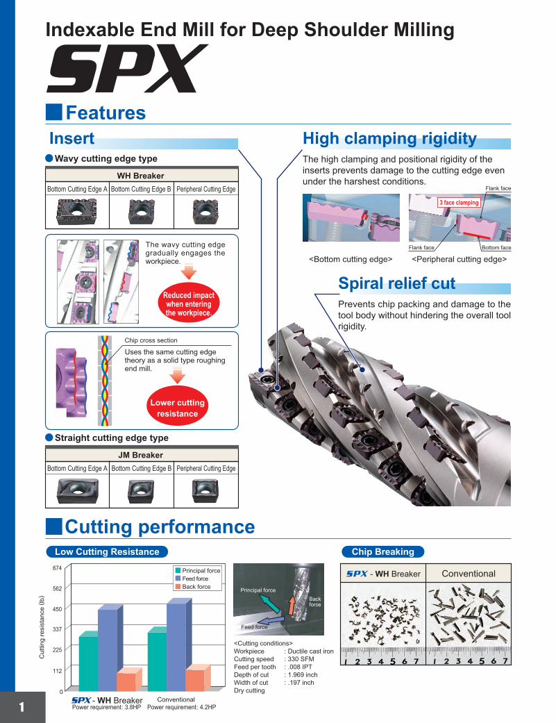
Insert
Reduced impactwhen enteringthe workpiece.
Lower cuttingresistance
Chip BreakingLow Cutting Resistance
Principal forceBack force
Feed force
ConventionalPrincipal forceFeed forceBack force
Power requirement: 3.8HPConventional- WH Breaker
- WH Breaker
Power requirement: 4.2HP
Cut
ting
resi
stan
ce ( l
b)
Bottom faceFlank face
<Bottom cutting edge> <Peripheral cutting edge>
Prevents chip packing and damage to the tool body without hindering the overall tool rigidity.
The high clamping and positional rigidity of the inserts prevents damage to the cutting edge even under the harshest conditions.
High clamping rigidity
Chip cross section
The wavy cutting edge gradually engages the workpiece.
Uses the same cutting edge theory as a solid type roughing end mill.
Bottom Cutting Edge A Bottom Cutting Edge B Peripheral Cutting Edge
WH Breaker
Wavy cutting edge type
Bottom Cutting Edge A Bottom Cutting Edge B Peripheral Cutting Edge
JM Breaker
Straight cutting edge type
Flank face
3 face clamping
Spiral relief cut
<Cutting conditions>Workpiece : Ductile cast ironCutting speed : 330 SFMFeed per tooth : .008 IPTDepth of cut : 1.969 inchWidth of cut : .197 inchDry cutting
2
y
SPX
a
a
D1 L1 D4 L2 ap JPMX190412-oo
MPMX120412-oo
SPMX120408-oo
SPX4R05016WNES 4R05024WNS 4R05034WNM 4R05044WNL
SPX4R3224CAT50NS 4R3234CAT50NM 4R3244CAT50NL
a
a
a
a
a
a
a
2
2
2
2
2
2
2
24
34
44
16
24
34
44
4
4
4
4
4
4
4
2.000
2.000
2.000
1.969
1.969
1.969
1.969
11.000
13.000
15.000
7.091
8.661
10.630
12.598
─
─
─
2.000
2.000
2.000
2.000
7.000
9.000
11.000
3.937
5.512
7.480
9.449
4.300
6.200
8.100
2.835
4.331
6.181
8.071
2
2
2
2
2
2
2
2
2
2
2
2
2
2
20
30
40
12
20
30
40
TKY25DTS55SPMX120408-WHMPMX120412-WHJPMX190412-WH
SPMX120408-JMMPMX120412-JMJPMX190412-JMMK1KS
90°L1
L2ap
øD4
øD1
90°
L1
CAT50
L2
ap
øD1
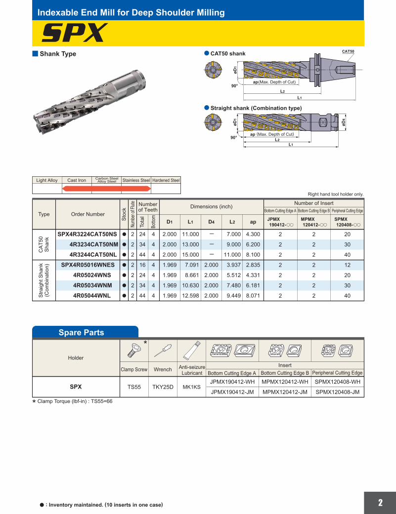
Shank Type
Indexable End Mill for Deep Shoulder Milling
Light Alloy Cast Iron Stainless Steel Hardened SteelCarbon SteelAlloy Steel
a : Inventory maintained. (10 inserts in one case)
(Max. Depth of Cut)
Straight shank (Combination type)
CAT50 shank
(Max. Depth of Cut)
Order Number
Numberof Teeth Dimensions (inch) Number of Insert
Bottom Cutting Edge A Bottom Cutting Edge B Peripheral Cutting Edge
Stra
ight
Sha
nk(C
ombi
natio
n)C
AT5
0S
hank
Type
Sto
ck
Botto
m
Tota
l
* Clamp Torque (lbf-in) : TS55=66
Right hand tool holder only.
Numb
er of
Flute
Spare Parts
HolderInsert
Clamp Screw Wrench
SPX
*
Bottom Cutting Edge A Bottom Cutting Edge B Peripheral Cutting EdgeAnti-seizure
Lubricant
3
SPX
D1 L1 D9 L7 D8 W1 L8 ap
2.5003.000
3.5003.500
1.3391.654
.219
.2812.2802.280
.539
.669.375.500
1.0001.250
JPMX140412-oo
MPMX120412-oo
SPMX120408-oo
SPX4UR2524CA22A 4UR0324DA22A
a
a
44
2424
44
22
22
2020
R
&2.500"&3.000"
HSCUF50028 62528
D1
NEW
D1 L1 D9 L7 D8 W1 L8 ap
6380
8585
2638
68
5858
1317
9.512.7
25.4(1.000″)31.75(1.250″)
JPMX140412-oo
MPMX120412-oo
SPMX120408-oo
SPX4R06324CA058A 4R08024DA058A
s
s
44
2424
44
22
22
2020
R
&63mm&80mm
HSC12070 16065
D1
NEW
D1 L1 D9 L7 D8 W1 L8 ap
6380
8585
2840
78
5858
1317
12.414.4
2732
JPMX140412-oo
MPMX120412-oo
SPMX120408-oo
SPX4-063A24A058RA -080A24A058RA
s
s
44
2424
44
22
22
2020
R
&63mm&80mm
HSC12070 16065
D1
NEW
a s
øD8
L1
L7 L8
øD1
ap
øD9
W1
øD8
L1
L7 L8
øD1
ap
øD9
W1
øD8
L1
L7 L8
øD1
ap
øD9
W1
: Inventory maintained.(10 inserts in a case) : Inventory maintained in Japan.
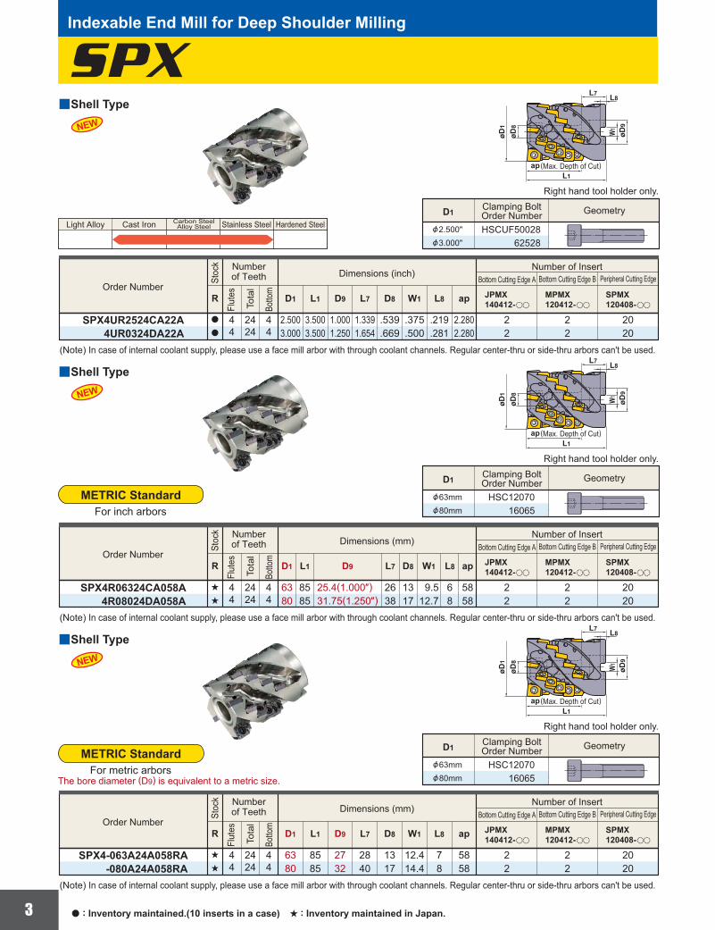
yShell Type
Indexable End Mill for Deep Shoulder Milling
Right hand tool holder only.
(Note) In case of internal coolant supply, please use a face mill arbor with through coolant channels. Regular center-thru or side-thru arbors can't be used.
Geometry
Order NumberDimensions (inch)
Number of InsertBottom Cutting Edge A Bottom Cutting Edge B Peripheral Cutting Edge
Numberof TeethSt
ock
Botto
m
Flut
es
Tota
l
Clamping BoltOrder Number
Light Alloy Cast Iron Stainless Steel Hardened SteelCarbon SteelAlloy Steel
The bore diameter (D9) is equivalent to a metric size.
METRIC StandardFor metric arbors
(Max. Depth of Cut)
yShell Type
Right hand tool holder only.
(Note) In case of internal coolant supply, please use a face mill arbor with through coolant channels. Regular center-thru or side-thru arbors can't be used.
Geometry
Order NumberDimensions (mm)
Number of InsertBottom Cutting Edge A Bottom Cutting Edge B Peripheral Cutting Edge
Numberof TeethSt
ock
Botto
m
Flut
es
Tota
l
Clamping BoltOrder Number
METRIC StandardFor inch arbors
(Max. Depth of Cut)
yShell Type
Right hand tool holder only.
(Note) In case of internal coolant supply, please use a face mill arbor with through coolant channels. Regular center-thru or side-thru arbors can't be used.
Geometry
Order NumberDimensions (mm)
Number of InsertBottom Cutting Edge A Bottom Cutting Edge B Peripheral Cutting Edge
Numberof TeethSt
ock
Botto
m
Flut
es
Tota
l
Clamping BoltOrder Number
(Max. Depth of Cut)
4
M
M
M
a a
a a
a a
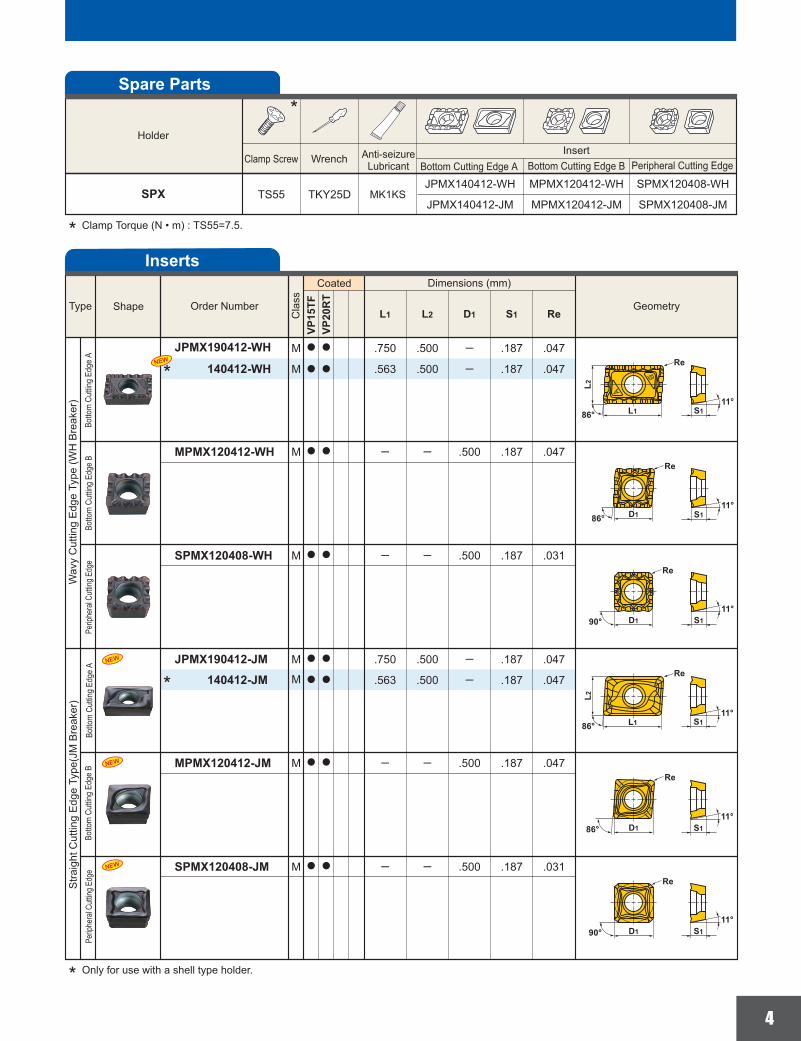
.500 ─ .187 .047.750
─ .500 .187 .031─
─ .500 .187 .047─
ReS1D1L2L1VP
15TF
VP20
RT
a a .500 ─ .187 .047.563
M
M
M
M
M
a a
a a
a a
.500 ─ .187 .047.750
─ .500 .187 .031─
─ .500 .187 .047─
a a .500 ─ .187 .047.563
NEW
NEW
NEW
NEW
TKY25DTS55SPMX120408-WHMPMX120412-WHJPMX140412-WH
SPMX120408-JMMPMX120412-JMJPMX140412-JMMK1KS
S111°
86°
Re
L1
L2
S111°
D1
Re
86°
D1 S111°
90°
Re
S111°
D190°
Re
S111°
86° D1
Re
S111°
Re
86° L1
L2
GeometryOrder Number
Dimensions (mm)
Inserts
Type
* Only for use with a shell type holder.
* Clamp Torque (N • m) : TS55=7.5.
*
*
Shape
Coated
Botto
m C
uttin
g Ed
ge A
Botto
m C
uttin
g Ed
ge B
Perip
hera
l Cut
ting
Edge
Botto
m C
uttin
g Ed
ge A
Botto
m C
uttin
g Ed
ge B
Perip
hera
l Cut
ting
Edge
Cla
ss
Wav
y C
uttin
g E
dge
Type
(WH
Bre
aker
) S
traig
ht C
uttin
g E
dge
Type
(JM
Bre
aker
)Spare Parts
HolderInsert
Clamp Screw Wrench
SPX
*
Bottom Cutting Edge A Bottom Cutting Edge B Peripheral Cutting EdgeAnti-seizure
Lubricant
JPMX190412-WH
140412-WH
SPMX120408-WH
MPMX120412-WH
JPMX190412-JM140412-JM
SPMX120408-JM
MPMX120412-JM
5
P
K
S
M
ae ap fzvc
<4D1
<2D1
<4D1
<2D1
<4D1
<2D1
<4D1
<2D1
<4D1
<4D1
<4D1
<4D1
<4D1
<2D1
<.394
<.394
<.394
<.394
<.394
<.394
<.394
<.394
<.394
<.394
<.394
<.394
<.394
<.394
.006─.010
.006─.010
.006─.010
.006─.010
.004─.008
.004─.008
.004─.008
.004─.008
.006─.016
.004─.010
.006─.014
.004─.008
.003─.005
.003─.005
180─350HB
<180HBVP15TF
WHVP15TF
JMVP15TF
WHVP15TF
JMVP15TF
WHVP15TF
JMVP20RT
WHVP20RT
JMVP15TF
WHVP15TF
JMVP15TF
WHVP15TF
JMVP20RT
WHVP20RT
JM
395(330─460)
395(330─460)
260(230─395)
260(230─395)
260(200─330)
260(200─330)
260(230─395)
260(230─395)
330(260─395)
330(260─395)
260(200─330)
260(200─330)
130(115─165)
130(115─165)
<300HB
<200HB
<350HB
y
P
K
S
M
ae ap fzvc
<.394
<.394
<.394
<.394
<.394
<.394
<.394
<.394
<1.969
<1.575
<1.575
<1.181
<.394
<.394
D1
D1
D1
D1
D1
D1
D1
D1
D1
D1
D1
D1
D1
D1
.004─.010
.004─.006
.004─.010
.004─.006
.004─.010
.004─.006
.004─.010
.004─.006
.006─.010
.004─.008
.006─.010
.004─.008
.003─.005
.003─.005
180─350HB
<180HBVP15TF
WHVP15TF
JMVP15TF
WHVP15TF
JMVP15TF
WHVP15TF
JMVP20RT
WHVP20RT
JMVP15TF
WHVP15TF
JMVP15TF
WHVP15TF
JMVP20RT
WHVP20RT
JM
200(165─395)
200(165─395)
200(165─330)
200(165─330)
165(130─260)
165(130─260)
200(165─395)
200(165─395)
165(130─260)
165(130─260)
130(115─260)
130(115─260)
115(100─165)
115(100─165)
<300HB
<200HB
<350HB
y
(inch) (inch)(SFM)
(inch) (inch)(SFM)
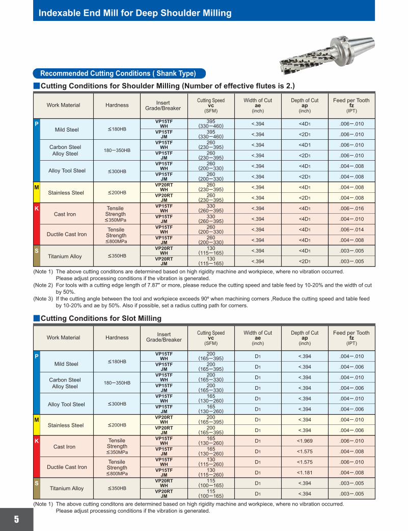
Indexable End Mill for Deep Shoulder Milling
Cutting Conditions for Shoulder Milling (Number of effective flutes is 2.)
Work Material HardnessWidth of Cut Depth of Cut Feed per Tooth
Mild Steel
(IPT)
Cutting Speed
Cutting Conditions for Slot Milling
Work Material HardnessWidth of Cut Depth of Cut Feed per Tooth
Titanium Alloy
(IPT)
Cutting Speed
(Note 1) The above cutting conditons are determined based on high rigidity machine and workpiece, where no vibration occurred. Please adjust processing conditions if the vibration is generated.
(Note 1) The above cutting conditons are determined based on high rigidity machine and workpiece, where no vibration occurred. Please adjust processing conditions if the vibration is generated.(Note 2) For tools with a cutting edge length of 7.87″ or more, please reduce the cutting speed and table feed by 10-20% and the width of cut by 50%.(Note 3) If the cutting angle between the tool and workpiece exceeds 90º when machining corners ,Reduce the cutting speed and table feed by 10-20% and ae by 50%. Also if possible, set a radius cutting path for corners.
Carbon SteelAlloy Steel
Cast Iron
Ductile Cast Iron
Titanium Alloy
Stainless Steel
Alloy Tool Steel
TensileStrength<350MPa
TensileStrength<800MPa
TensileStrength<350MPa
TensileStrength<800MPa
InsertGrade/Breaker
Mild Steel
Carbon SteelAlloy Steel
Cast Iron
Ductile Cast Iron
Stainless Steel
Alloy Tool Steel
InsertGrade/Breaker
Recommended Cutting Conditions ( Shank Type)
6
P
K
S
M
ae ap fzvc
<0.5D1
>0.5D1
<0.5D1
>0.5D1
<0.5D1
>0.5D1
<0.5D1
>0.5D1
<0.5D1
>0.5D1
<0.5D1
>0.5D1
<0.5D1
>0.5D1
<0.5D1
>0.5D1
<0.5D1
>0.5D1
<.394
<.394
<.394
<.394
<.394
<.394
<.394
<.394
<.394
<.394
<.394
<.394
<.394
<.394
<.394
<.394
<.394
<.394
.006─.012
.006─.010
.006─.012
.006─.010
.004─.010
.004─.006
.004─.010
.004─.008
.010─.016
.010─.016
.006─.012
.006─.010
.008─.014
.008─.014
.006─.012
.006─.012
.003─.004
.003─.004
180─350HB
<180HB VP15TFJM
VP15TFJM
VP15TFJM
VP20RTJM
VP15TFWH
VP15TFJM
VP15TFWH
VP15TFJM
VP20RTJM
395(330─460)
395(330─460)
395(260─425)
330(260─395)
330(200─360)
260(200─330)
460(330─490)
395(330─460)
395(260─425)
330(260─395)
395(260─425)
330(260─395)
330(200─360)
260(200─360)
330(200─395)
260(200─395)
150(115─165)
150(115─165)
<300HB
<200HB
<350HB
y
P
K
S
M
ae ap fzvc
<0.25D1
<0.25D1
<.394
<.394
<0.25D1
<0.6D1
<0.25D1
<0.6D1
<0.25D1
<0.5D1
<0.25D1
<0.5D1
<0.25D1
D1
D1
D1
D1
D1
D1
D1
D1
D1
D1
D1
D1
D1
.006─.010
.006─.010
.004─.008
.004─.006
.004─.010
.004─.008
.004─.008
.004─.006
.004─.010
.004─.008
.004─.008
.004─.006
.002─.004
180─350HB
<180HB VP15TFJM
VP15TFJM
VP15TFJM
VP20RTJM
VP15TFWH
VP15TFJM
VP15TFWH
VP15TFJM
VP20RTJM
395(330─460)
330(260─395)
260(200─330)
330(260─460)
260(200─330)
200(165─330)
260(200─330)
200(165─330)
260(200─330)
200(165─330)
260(200─330)
200(165─330)
130(115─165)
<300HB
<200HB
<350HB
y
(inch) (inch)(SFM)
(inch) (inch)(SFM)
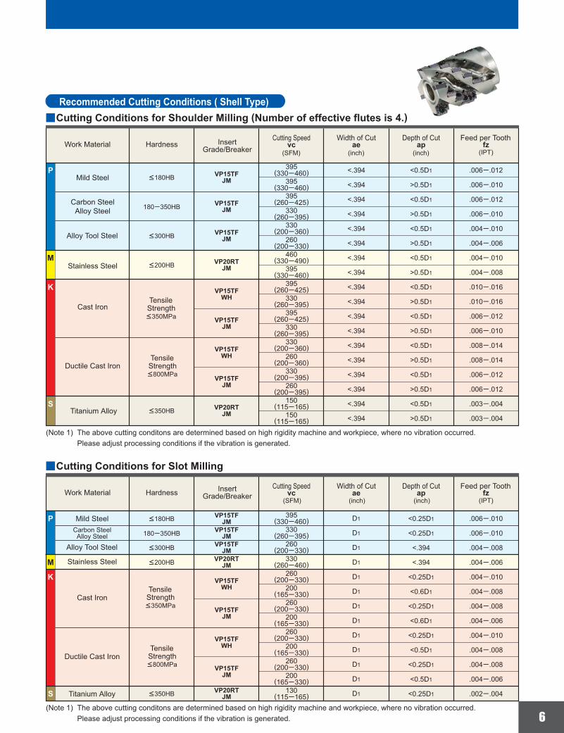
Recommended Cutting Conditions ( Shell Type)Cutting Conditions for Shoulder Milling (Number of effective flutes is 4.)
Work Material HardnessWidth of Cut Depth of Cut Feed per Tooth
Titanium Alloy
(IPT)
Cutting Speed
Cutting Conditions for Slot Milling
Work Material HardnessWidth of Cut Depth of Cut Feed per Tooth
Titanium Alloy
(IPT)
Cutting Speed
(Note 1) The above cutting conditons are determined based on high rigidity machine and workpiece, where no vibration occurred. Please adjust processing conditions if the vibration is generated.
(Note 1) The above cutting conditons are determined based on high rigidity machine and workpiece, where no vibration occurred. Please adjust processing conditions if the vibration is generated.
Mild Steel
Carbon SteelAlloy Steel
Cast Iron
Ductile Cast Iron
Stainless Steel
Alloy Tool Steel
InsertGrade/Breaker
Mild SteelCarbon Steel
Alloy Steel
Cast Iron
Ductile Cast Iron
Stainless Steel
Alloy Tool Steel
InsertGrade/Breaker
TensileStrength<350MPa
TensileStrength<800MPa
TensileStrength<350MPa
TensileStrength<800MPa
EXP-09-N045Printed in U.S.A. 07/10
Av. La Cañada No.16, Parque Industrial Bernardo Quintana, El Marques, Queretaro, CP 76246 MexicoTEL. +52-442-221-6136/+52-442-221-6137/+52-442-221-6150 FAX. +52-442-221-6134
11250 Slater Avenue, Fountain Valley, CA 92708, U.S.ATEL. 714-352-6100 FAX. 714-668-1320Customer Service: (800)523-0800 Technical Support: (800)486-2341Chicago Branch Office: 1314B N.Plum Grove Rd., Schaumburg, Illinois 60173, U.S.A
TEL. 847-252-6300 FAX. 847-519-1732Toronto Branch Office: 6535 Millcreek Drive, Unit 63 & 64, Mississauga, Ontario, Canada L5N 2M2
TEL. 905-814-0240 FAX. 905-814-0245
Mitsubishi Carbide Home page : (Tools specifications subject to change without notice.)
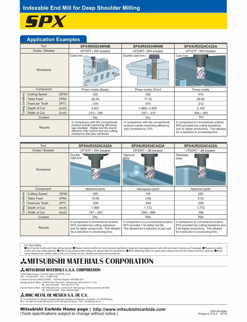
SPXSPX4R05034WNM
33020.04.016
4.921.315─.394
SPX4R05034WNM
33017.52.014
1.969─3.937.197─.315
SPX4UR2524CA22A
41029.84.012
2.165.394─.591
SPX4UR2524CA22A
39519.09.008
1.969.197─.591
SPX4UR2524CA22A
1503.58.004
1.772.394─.984
SPX4UR2524CA22A
3959.52.004
1.772.394
For Your SafetyaDon't handle inserts and chips without gloves. aPlease machine within the recommended application range and exchange expired tools with new ones in advance of breakage. aPlease use safety covers and wear safety glasses. aWhen using compounded cutting oils, please take fire precautions. aWhen attaching inserts or spare parts, please use only the correct wrench or spanner. aWhen using rotating tools, please make a trial run to check run-out, vibration and abnormal sounds etc.
Application Examples
Dry
Cast iron Ductile cast iron
Press molds (Trim)
Dry Dry
Cast iron
Press molds
Indexable End Mill for Deep Shoulder Milling
Press molds (Base)
Dry
Ductilecast iron
Titaniumalloy
Aerospace parts
Wet
Stainlesssteel
Machine parts
Wet
Machine parts
VP15TF / WH breaker VP20RT / WH breaker VP15TF / WH breaker
VP15TF / WH breaker VP20RT / JM breaker VP20RT / JM breaker
ToolGrade / Breaker
Cuttin
g Co
nditio
ns
Workpiece
Results
Coolant
Cutting Speed (SFM)Table Feed (IPM)Feed per Tooth (IPT)Depth of Cut (inch)Width of Cut (inch)
Component
ToolGrade / Breaker
Cuttin
g Co
nditio
ns
Workpiece
Results
Coolant
Cutting Speed (SFM)Table Feed (IPM)Feed per Tooth (IPT)Depth of Cut (inch)Width of Cut (inch)
Component
In comparison with the conventional product overall machining efficiency was doubled. Stable tool life due to effective chip control and low cutting resistance was also achieved.
In comparison to conventional product, SPX provided low cutting resistance and 3x higher productivity. This allowed for a reduction in processing time.
In comparison to conventional product, SPX provided low cutting resistance and 3x higher productivity. This allowed for a reduction in processing time.
In comparison to conventional product, SPX provided low cutting resistance and 4.8x higher productivity. This allowed for a reduction in processing time.
In comparison to a conventional product, SPX provided 1.5x better tool life. This allowed for a reduction in tool cost.
In comparison with the conventional product overall machining efficiency was increased by 70%.