Embed Size (px)
Citation preview

CAEN Tools for Discovery
n
Electronic Instrumentation
User Manual UM2462
SY4527 - SY4527LC Power Supply Systems
Rev. 12 - 9 June 2015

Purpose of this Manual This document is the SY4527 - SY4527LC Power Supply Systems User's Manual; it contains information about the installation, the configuration and the use of the Power Supply System.
Change Document Record Date Revision Changes
16 March 2012 0 Preliminary release
3 April 2012 1 Output Power notes
20 April 2012 2 Installation procedures
26 November 2012 3 Reboot procedures, new HiVoCS
27 February 2013 4 Firmware upgrade options
26 March 2013 5 Updated introduction
16 October 2013 6 Added SY4527LC specifications
28 November 2013 7 Details on TRIP function
13 December 2013 8 Updated power requirements
23 January 2014 9 Updated table 2 (packaging)
14 March 2014 10 Updated § 8 (EPICS; Upgrade)
2 July 2014 11 Updated Reset Configuration Flag
9 June 2015 12 Added SSH connection
Symbols, abbreviated terms and notation T.B.D.
Reference Document
CAEN S.p.A. Via Vetraia, 11 55049 Viareggio (LU) - ITALY Tel. +39.0584.388.398 Fax +39.0584.388.959 [email protected] www.caen.it
© CAEN SpA – 2011
Disclaimer
No part of this manual may be reproduced in any form or by any means, electronic, mechanical, recording, or otherwise, without the prior written permission of CAEN SpA.
CAEN will repair or replace any product within the guarantee period if the Guarantor declares that the product is defective due to workmanship or materials and has not been caused by mishandling, negligence on behalf of the User, accident or any abnormal conditions or operations.
CAEN declines all responsibility for damages or injuries caused by an improper use of the Modules due to negligence on behalf of the User. It is strongly recommended to read thoroughly the CAEN User's Manual before any kind of operation. CAEN reserves the right to change partially or entirely the contents of this Manual at any time and without giving any notice.
Disposal of the Product The product must never be dumped in the Municipal Waste. Please check your local regulations for disposal of electronics products.
MADE IN ITALY : We stress the fact that all the boards are made in Italy because in this globalized world, where getting the lowest possible price for products sometimes translates into poor pay and working conditions for the people who make them, at least you know that who made your board was reasonably paid and worked in a safe environment. (this obviously applies only to the boards marked "MADE IN ITALY", we cannot attest to the manufacturing process of "third party" boards).

CAEN Electronic Instrumentation
UM2462 – SY4527 - SY4527LC Power Supply Systems 3
Index Index.......................................................................................................................................... 3
List of Figures ............................................................................................................................. 4
1. Introduction ....................................................................................................................... 6
2. Safety and operation requirements .................................................................................... 8 General information ................................................................................................................................................. 8 Injury Precautions ..................................................................................................................................................... 8 Product Damage Precautions ................................................................................................................................... 8 EC Certifications and Compliance ............................................................................................................................. 9 Terms in this Manual ................................................................................................................................................ 9 Safety Terms and Symbols on the Product ............................................................................................................... 9 General Operation Requirements ............................................................................................................................ 9 Power cords .............................................................................................................................................................. 9
3. Hardware installation ....................................................................................................... 10 Installation .............................................................................................................................................................. 10
4. Functional description ...................................................................................................... 11 Technical specifications .......................................................................................................................................... 11 A4528 Output Power .............................................................................................................................................. 12 A4528 CPU Section ................................................................................................................................................. 13 A4531 Primary Power Supply Section (SY4527) ..................................................................................................... 16 Mainframe panel .................................................................................................................................................... 17
MAIN switch .........................................................................................................................................................................18 Fuse ......................................................................................................................................................................................18 Earth .....................................................................................................................................................................................18 AC Input ...............................................................................................................................................................................19
5. System and channel control .............................................................................................. 20 Organization ........................................................................................................................................................... 20 LOCAL/REMOTE Power-On (SY4527) ...................................................................................................................... 21 System control ........................................................................................................................................................ 22
NIM / TTL standard selection ...............................................................................................................................................22 LOCAL/REMOTE Channel Enable ..........................................................................................................................................22 VSEL command .....................................................................................................................................................................22 ISEL command ......................................................................................................................................................................23 KILL command ......................................................................................................................................................................23 RESET command...................................................................................................................................................................23 INTERLOCK command ..........................................................................................................................................................24 HV SYNC ...............................................................................................................................................................................24 FAN .......................................................................................................................................................................................24
System status monitoring ....................................................................................................................................... 24 Over Current ........................................................................................................................................................................25 Under Voltage ......................................................................................................................................................................25 Over Voltage ........................................................................................................................................................................25 Trip .......................................................................................................................................................................................25 Reset flag ..............................................................................................................................................................................26 Check passed ........................................................................................................................................................................26 GEN ......................................................................................................................................................................................26 CH-ON ..................................................................................................................................................................................26 Over Temperature................................................................................................................................................................26 Fan Failure ............................................................................................................................................................................27 Pwr Failure ...........................................................................................................................................................................27
6. Operating modes .............................................................................................................. 28 Standalone operation ............................................................................................................................................. 28
Software Version ..................................................................................................................................................................28 Remote operation via Host Computer .................................................................................................................... 29
7. System Power-On ............................................................................................................. 30

CAEN Electronic Instrumentation
UM2462 – SY4527 - SY4527LC Power Supply Systems 4
Preliminary check ................................................................................................................................................... 30 Local Power-On ....................................................................................................................................................... 30 Remote Power-On (SY4527) ................................................................................................................................... 31 Configuration .......................................................................................................................................................... 31 System Reset Flag Configuration ............................................................................................................................ 31
8. HiVoCS ............................................................................................................................. 32 System Log-in .......................................................................................................................................................... 32 Main Menu ............................................................................................................................................................. 33
Crate Map ............................................................................................................................................................................33 Channels Controller..............................................................................................................................................................34 Sessions ................................................................................................................................................................................35 Documentation ....................................................................................................................................................................35
Setting Menu .......................................................................................................................................................... 35 Users management ..............................................................................................................................................................36 Change password .................................................................................................................................................................37 Networking...........................................................................................................................................................................37 DHCP Server .........................................................................................................................................................................38 Remote Assistance ...............................................................................................................................................................39 System time .........................................................................................................................................................................39 License Manager ..................................................................................................................................................................39 EPICS ....................................................................................................................................................................................41 System Reboot .....................................................................................................................................................................42
Upgrade menu ........................................................................................................................................................ 42 Upgrade trouble-shooting ....................................................................................................................................................43
9. Secure shell connection .................................................................................................... 45
10. Trip handling .................................................................................................................... 46 Internal Trip ............................................................................................................................................................ 46 External Trip ............................................................................................................................................................ 46
List of Figures Fig. 1 – SY4527 Universal Multichannel Power Supply System .................................................................... 6 Fig. 2 – SY4527LC Universal Multichannel Power Supply System ................................................................ 7 Fig. 3 – Maximum Output Power vs. Power Supply Units and power voltage line .................................... 12 Fig. 4 – A4528 CPU Full Version .................................................................................................................. 13 Fig. 5 – A4531 Primary Power Supply ......................................................................................................... 16 Fig. 6 – SY4527 back panel ......................................................................................................................... 17 Fig. 7 – SY4527LC panel .............................................................................................................................. 17 Fig. 8 – SY4527 System Block Diagram ....................................................................................................... 20 Fig. 9 – SY4527LC System Block Diagram ................................................................................................... 21 Fig. 10 – Standalone Operation with LCD Touchscreen ............................................................................. 28 Fig. 11 – Remote Operation via Host Computer ........................................................................................ 29 Fig. 12 – HiVoCS Log in window ................................................................................................................. 32 Fig. 13 – HiVoCS Main menu ...................................................................................................................... 33 Fig. 14 – HiVoCS Crate Map ........................................................................................................................ 33 Fig. 15 – CAEN HVPSS Channels Controller ................................................................................................ 34 Fig. 16 – CAEN HVPSS Control options ....................................................................................................... 34 Fig. 17 – HiVoCS session parameters ......................................................................................................... 35 Fig. 18 – Setting Menu................................................................................................................................ 35 Fig. 19 – HiVoCS local user status ............................................................................................................... 36 Fig. 20 – HiVoCS new user registration ...................................................................................................... 36 Fig. 21 – HiVoCS Change password form .................................................................................................... 37 Fig. 22 – HiVoCS network status ................................................................................................................. 37 Fig. 23 – HiVoCS DHCP Server form ............................................................................................................ 38 Fig. 24 – HiVoCS remote assistance ........................................................................................................... 39 Fig. 25 – HiVoCS System time setting ......................................................................................................... 39 Fig. 26 – System Add On License Manager ................................................................................................ 40

CAEN Electronic Instrumentation
UM2462 – SY4527 - SY4527LC Power Supply Systems 5
Fig. 27 – EPICS Service configuration menu ............................................................................................... 41 Fig. 28 – EPICS Process Variables ............................................................................................................... 42 Fig. 29 – HiVoCS Upgrade menu ................................................................................................................. 42 Fig. 30 – Upgrade “Update done” message ............................................................................................... 43 Fig. 31 – SW1 location on A4528 CPU mother board ................................................................................. 44 Fig. 32 – Telnet user connection ................................................................................................................ 45
List of Tables Table 1 – Available Items ............................................................................................................................. 7 Table 2 – SY4527 Technical specifications ................................................................................................. 11 Table 3 – CPU Front Panel I/O signals ........................................................................................................ 14 Table 4 – CPU Front Panel Displays ............................................................................................................ 15 Table 5 – CPU Front Panel Switches ........................................................................................................... 15 Table 6 – Primary Power Supply Signals and Switches ............................................................................... 17 Table 7 – Primary Power Supply Displays................................................................................................... 17

CAEN Electronic Instrumentation
UM2462 – SY4527 - SY4527LC Power Supply Systems 6
1. Introduction
Fig. 1 – SY4527 Universal Multichannel Power Supply System
The SY4527 system is the fully equipped experiment version of a new line of power supply systems which represent CAEN's latest proposal in the matter of High Voltage and Low Voltage Power Supplying. This system outlines a completely new approach to power generation and distribution by allowing the housing, in the same mainframe, of a wide range of boards with different functions, such as High/Low Voltage boards, generic I/O boards (temperature, pressure monitors, etc.) and branch controllers, where the latter are used to control other remote generators and distributors. Modularity, flexibility and reliability are the key-points of its design, enabling this module to meet the requirements needed in a wide range of experimental conditions. The mainframe is housed in a 19"-wide, 8U-high euro-mechanics rack and hosts four main sections:
the Board Section, with 16 slots to house power supply boards, distributors and branch controllers;
the Fan Tray Section, housing 6 fans arranged on two rows, with programmable rotation speed regulation;
the Power Supply Section, which consists of the Primary power supply and up to 3 “Booster” units;
the CPU and Front Panel Section which includes all interface facilities.
The CPU controller is available in 3 different versions: BASIC, ADVANCED and FULL.
The BASIC version provides all communication interfaces, RESET control, INTERLOCK control and status LEDs.
The ADVANCED version also provides the beam handshake management signals (CH-ON, GEN, VSEL, ISEL).
The FULL version provides the complete set of connectors, ENABLE control section, and fan speed control.
The User Software Interface features the usual friendliness of the previous CAEN systems which now also can optionally include a colour touchscreen LCD (two version are available: 10.4” and 5.7”). Modularity has been one of the leading criteria in the design and development of the system: both the Power Supply Section and the Board Section are completely modular. The Power Supply Section allows different configurations with up to 4 power supply units per mainframe (up to 4.2kW), while the Board Section can house up to 16 boards able to perform different functions. The complete line of power supply boards and distributors that has been specially developed for SY1527 are fully compatible with the new mainframes. The minimum working system configuration consists of the Primary power supply, one CPU controller and one board. The system allows also to deal with power supply solutions composed by "branch controllers" (housed in the system mainframe) and on-detector "remote boards" (manufactured in order to be magnetic field and radiation tolerant). A sophisticated trip handling via software allows to control and correlate trip conditions on the channels of the crate. Live insertion and extraction of the boards, which reduces the down time of the global system and eases access to the computing core and peripherals of the system, complete the system flexibility.
Easy interfacing is another key-point of the SY4527 system. The Gigabit Ethernet interface (and the optional Wi- Fi interface) allows both an easy web access and the connection via OPC Server to a SCADA control system. Enhanced software programming features an unified command set independent from the interface used to communicate with the system. The Power Supply Section and Board Section can be externally synchronised via front panel connectors. Handy maintenance and upgrading, which constitute a major issue in the reliability of a system, are further guaranteed by the possibility of accessing and servicing the system via network facilities. A USB service port allows debugging, configuration and firmware upgrade.
Two new powerful improvements have been carried out on the new backplane:
A new 48V Power Bus distribution
FLEXRAY Fast Serial Link

CAEN Electronic Instrumentation
UM2462 – SY4527 - SY4527LC Power Supply Systems 7
Fig. 2 – SY4527LC Universal Multichannel Power Supply System
The SY4527LC system is a simplified version of the SY4527 power supply system; it shares most of its feature with its bigger brother, with the following exceptions:
• the Board Section has 10 slots to house power supply boards, distributors and branch controllers;
• the Power Supply Section hosts the 600 W non expandable power supply unit
• the CPU provides all communication interfaces, RESET control, INTERLOCK control and status LED
• colour touchscreen LCD for local control is not available
Table 1 – Available Items
Code Item Description
WSY4527FLLXA SY4527 Universal Multichannel Power Supply System - FULL 600W
WSY4527ADVXA SY4527 Universal Multichannel Power Supply System - ADVANCED 600W
WSY4527BSCXA SY4527 Universal Multichannel Power Supply System - BASIC 600W
WSY4527PREXA SY4527 SY4527 Premium - Includes SY4527 FULL, A4534, A4535, SW4536
WSY4527LCXAA SY4527LC 10 Slot LOW COST Universal Multichannel Power Supply System
WA4528FLLXAA A4528 SY4527/SY5527 CPU Module FULL
WA4528ADVXAA A4528 SY4527/SY5527 CPU Module ADVANCED
WA4528BSCXAA A4528 SY4527/SY5527 CPU Module BASIC
WA4531XAAAAA A4531 SY4527/SY5527 Primary Power Supply 600W
WA4532S600XA A4532 SY4527/5527 Optional Single Power Supply Unit 600W
WA4533D1200X A4533 SY4527/5527 Optional Double Power Supply Unit 1200W
WA4534XAAAAA A4534 10.4" LCD Touch screen color Display Unit
WA4537XAAAAA A4537 5.7" LCD Touchscreen color Display Unit
WA4535XAAAAA A4535 SY4527/SY5527 Wi-Fi Dongle for Wireless connectivity
WSW4536XAAAA SW4536 SY4527/SY5527 Control software functionality enhancement activation code
CAEN Electronic Instrumentation
UM2462 – SY4527 - SY4527LC Power Supply Systems 8
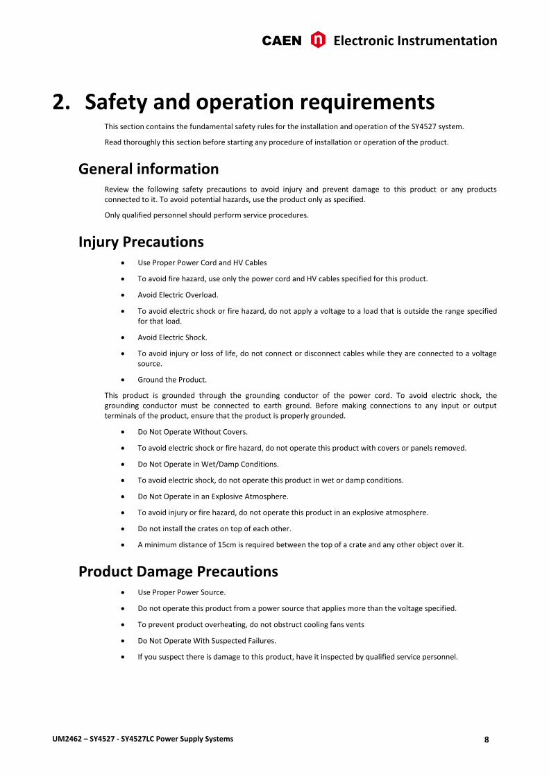
2. Safety and operation requirements This section contains the fundamental safety rules for the installation and operation of the SY4527 system.
Read thoroughly this section before starting any procedure of installation or operation of the product.
General information Review the following safety precautions to avoid injury and prevent damage to this product or any products connected to it. To avoid potential hazards, use the product only as specified.
Only qualified personnel should perform service procedures.
Injury Precautions Use Proper Power Cord and HV Cables
To avoid fire hazard, use only the power cord and HV cables specified for this product.
Avoid Electric Overload.
To avoid electric shock or fire hazard, do not apply a voltage to a load that is outside the range specified for that load.
Avoid Electric Shock.
To avoid injury or loss of life, do not connect or disconnect cables while they are connected to a voltage source.
Ground the Product.
This product is grounded through the grounding conductor of the power cord. To avoid electric shock, the grounding conductor must be connected to earth ground. Before making connections to any input or output terminals of the product, ensure that the product is properly grounded.
Do Not Operate Without Covers.
To avoid electric shock or fire hazard, do not operate this product with covers or panels removed.
Do Not Operate in Wet/Damp Conditions.
To avoid electric shock, do not operate this product in wet or damp conditions.
Do Not Operate in an Explosive Atmosphere.
To avoid injury or fire hazard, do not operate this product in an explosive atmosphere.
Do not install the crates on top of each other.
A minimum distance of 15cm is required between the top of a crate and any other object over it.
Product Damage Precautions Use Proper Power Source.
Do not operate this product from a power source that applies more than the voltage specified.
To prevent product overheating, do not obstruct cooling fans vents
Do Not Operate With Suspected Failures.
If you suspect there is damage to this product, have it inspected by qualified service personnel.

CAEN Electronic Instrumentation
UM2462 – SY4527 - SY4527LC Power Supply Systems 9
EC Certifications and Compliance Use in conformity of the definition with fully equipped mainframe with fully closed slots by boards or dummy panels. Sufficient cooling and mains connection must be secured according to regulations. Signal lines length during all tests was less than 3 m. Admitted for powering by industrial mains only.
Terms in this Manual WARNING: Warning statements identify conditions or practices that could result in injury or loss of life.
CAUTION: Caution statements identify conditions or practices that could damage this product or other property.
Safety Terms and Symbols on the Product These terms may appear on the product:
DANGER indicates an injury hazard immediately accessible as you read the marking.
WARNING indicates an injury hazard not immediately accessible as you read the marking.
CAUTION indicates a hazard to property including the product.
The following label is printed on the back panel of the product:
These symbols mean:
DANGER High Voltage
ATTENTION Refer to Manual
General Operation Requirements Before operation, check the following requirements:
Operating temperature: 5÷40°C (dry atmosphere) Max. length of cables: according to cable specifications
Power cords The SY4527 system is provided with power cord, suitable to configuration requirements, as reported on the following back panel label:
The SY4527LC system is provided with power cord, suitable to configuration requirements, as reported on the following panel label:

CAEN Electronic Instrumentation
UM2462 – SY4527 - SY4527LC Power Supply Systems 10
3. Hardware installation
Installation Before installing the system, make sure you have read thoroughly the safety rules and installation requirements.
All installation instructions are provided by the SY4527 Quickstart Guide.

CAEN Electronic Instrumentation
UM2462 – SY4527 - SY4527LC Power Supply Systems 11
4. Functional description
Technical specifications Table 2 – SY4527 Technical specifications
Version SY4527 SY4527LC
Packaging
19” 8U Euro-mechanics rack W: 19’’ (483 mm) H: 8U (355 mm) D: 747 mm (with handles) 667 mm (without handles)
19” 8U Euro-mechanics rack W: 19’’ (483 mm) H: 8U (355 mm) D: 556 mm (with handles) 489 mm (without handles)
Weight Mainframe(*): 18 kg Mainframe: 15 kg
Power Requirements
Voltage range 100/240 Vac; 50/60 Hz
Max current 25 A; Fuse 10x38 25A Rapid 600V 15A
Max power 5500 W @ 220 Vac 2750 W @ 110 Vac
1050 W @ 220 Vac 1020 W @ 110 Vac
Max. number of boards per crate 16 10
Max. number of Power Supply Units per crate 4 (1 Primary + 3 Optional)(**) 1
Primary Power Supply Unit Output Power 600 W with 220 Vac Mains; 550 W with 110 Vac Mains
Optional Power Supply Unit Output Power
Single Version: 600 W (220 Vac Mains); 550 W (110 Vac Mains) Double Version: 1200 W (220 Vac Mains); 1100 W (110 Vac Mains)
n.a.
Maximum. Output Power 4200 W @ 220 Vac 1990 W @ 110 Vac
600 W @220 Vac 550 W @ 110 Vac
CPU 3 versions: BASIC, ADVANCED and FULL
See p.13
Display
10.4” or 5.7” Colour Touchscreen LCD (optional) with two USB 2.0 ports for event logging, configuration backup & restore
n.a.
Communication Gigabit Ethernet, Wi-Fi (optional)
Software Graphical interface control software; OS Platforms: MS Windows, Linux HiVoCS tool
Enhanced Software (optional) Includes advanced features like Logging, Scripting, Alarm handling
Additional features OPC Server compatibility; FLEXRAY Fast Serial Link
Operating temperature From 5°C to +40°C
Operating humidity From 10% to +90% non-condensing
Storage temperature From -30°C to +80°C
Storage humidity From 5% to +90% non-condensing
(*) One Primary Power Supply (Mod.A4531) and one CPU(Mod.A4528) are included; boards are not included.
(**) See Fig. 3

CAEN Electronic Instrumentation
UM2462 – SY4527 - SY4527LC Power Supply Systems 12
A4528 Output Power The following chart shows the available typical output power depending on installed Power Supply Units and input power voltage line.
Fig. 3 – Maximum Output Power vs. Power Supply Units and power voltage line
Primary + 3xDouble PSU
Primary + 2xDouble PSU + Single PSU
Primary + 2xDouble PSU
Primary + Double PSU + Single PSU
Primary + Double PSU
Primary + Single PSU
Primary/SY4527LC
-
500
1.000
1.500
2.000
2.500
3.000
3.500
4.000
4.500
80
90
10
0
11
0
12
0
13
0
14
0
15
0
16
0
17
0
18
0
19
0
20
0
21
0
22
0
23
0
24
0
Po
we
r O
ut
(W)
Vac (RMS)

CAEN Electronic Instrumentation
UM2462 – SY4527 - SY4527LC Power Supply Systems 13
A4528 CPU Section The CPU Front Panel Section includes all interface facilities; it is available in 3 different versions: BASIC, ADVANCED and FULL: the BASIC version provides all the communication interfaces, the RESET control, the INTERLOCK control and status LEDs; the ADVANCED version also provides the beam handshake management connectors (CH-ON, GEN, VSEL, ISEL); the FULL version provides the complete set of panel connectors, the ENABLE control section, and the fan speed control. The CPU version installed on the SY4527LC shares the same features with the BASIC issue.
The tables below resume the front panel facilities of the 3 CPU versions.
Fig. 4 – A4528 CPU Full Version

CAEN Electronic Instrumentation
UM2462 – SY4527 - SY4527LC Power Supply Systems 14
Table 3 – CPU Front Panel I/O signals
Name Direction Electrical Specification Function
CPU Version
Full
Ad
van
ced
Bas
ic
SY4
52
7LC
CH-ON Out Std. NIM/TTL (selectable); 00-type LEMO connector.
at least one channel is ON X X
GEN Out Std. NIM/TTL (selectable); 00-type LEMO connector.
GENERAL STATUS indication; corresponds to the logic combination (defined by the user) of OVC, UNV, OVV, TRIP
X X
CHK PASS Out Std. NIM/TTL (selectable); 00-type LEMO connector.
initial system check successful and system ready
X
RSTFLAG Out Std. NIM/TTL (selectable); 00-type LEMO connector.
a RESET occurred according to user's settings (RESET FLAG window).
X
OVV Out Std. NIM/TTL (selectable); 00-type LEMO connector.
at least one channel is in Over Voltage
X
UNV Out Std. NIM/TTL (selectable); 00-type LEMO connector.
at least one channel is in Under Voltage
X
OVC Out Std. NIM/TTL (selectable); 00-type LEMO connector.
at least one channel is in Over Current.
X
TRIP Out Std. NIM/TTL (selectable); 00-type LEMO connector.
status of External Trip line 0 is HIGH (see p. 45)
X
VSEL In Std. NIM/TTL (selectable); 00-type LEMO connector.
channel voltage selection X X
ISEL In Std. NIM/TTL (selectable); 00-type LEMO connector.
channel current selection X X
KILL In Std. NIM/TTL (selectable); 00-type LEMO connector.
KILL from the front panel: it turns all channels off
X
HV SYNC MASTER
In Bidirectional differential signal 2-pin LEMO connectors.
sync clock for the PWS Units (RS485 Std., 1.25 MHz).
X
ENABLE In Std. NIM/TTL (selectable); 00-type LEMO connector.
remote enable. X
RESET In
Std. NIM/TTL (selectable); 00-type LEMO connector.
RESET from the front panel. If the duration of the RESET signal is > TRCPU=100÷200 ms, the CPU is reset; if it is > TRCH= TRCPU + 900 ms, also the boards are reset and the channels are turned off. Reset must be enabled via software (RESET FLAG window
X X X
INTERLOCK In open/closed contact; 00-type LEMO connector.
INTERLOCK command: it turns all the channels off as it is open/closed, according to the position of the relevant switch.
X X X
USB USB A female connector, USB 2.0 compliant
X X X
SERVICE USB B female connector, USB 2.0 compliant
X X X
ETH 10Base-T female connector, TTL signals (TCP/IP)
X X X

CAEN Electronic Instrumentation
UM2462 – SY4527 - SY4527LC Power Supply Systems 15
Table 4 – CPU Front Panel Displays
Name Description
CPU Version
Full
Ad
van
ced
Bas
ic
SY4
52
7LC
CH-ON Red LED, lights up as at least one channel is ON X X
GEN Red LED, lights up as GENERAL STATUS signal, corresponding to a logic combination (defined by the user) of OVC, UNV, OVV, TRIP, is TRUE
X X
CHK PASS Green LED, lights up as the initial system check has been performed successfully and the system is ready
X
RSTFLAG Red LED, lights up after a RESET X
OVV Red LED, lights up as at least one channel is in Over Voltage condition X
UNV Red LED, lights up as at least one channel is in Under Voltage condition X
OVC Red LED, lights up as at least one channel is in Over Current condition X
TRIP Red LED, lights up as status of External Trip line 0 is HIGH (see p. 45) X
TTL Green LED, lights up as the relevant standard is selected X X X
NIM Green LED, lights up as the relevant standard is selected X X X
VSEL Green LED, lights up as the relevant connector for voltage selection is TRUE X X
ISEL Green LED, lights up as the relevant connector for current selection is TRUE X X
KILL Green LED, lights up as the system is in KILL condition X
HV SYNC MASTER Red LED, lights up as the HV SYNC clock is internally generated X
ENABLE Red LED, lights up, as either the Local Enable mode is selected or as the Remote Enable mode is selected and the proper REM EN signal is sent in
X
RESET Red/orange LED, lights up as a RESET occurs: it is initially red and then becomes orange, depending on the duration of the RESET signal
X X X
INTERLOCK Green LED, lights up as the system is in INTERLOCK condition X X X
OVER TEMP Red LED, lights up as the Over Temperature condition occurs X X X
FAN FAIL Red LED, lights up as the Fan Failure condition occurs X X X
PWR FAIL Red LED, lights up as the Power Failure condition occurs X X X
HI Fan speed High X
MD Fan speed Medium X
LO Fan speed Low X
Table 5 – CPU Front Panel Switches
Name Description
CPU Version
Full
Ad
van
ced
Bas
ic
SY4
52
7LC
ENABLE Allows, respectively, to enable the channels locally or to disable them or to allow their remote enable via the proper ENABLE input signal
X
INTERLOCK Select whether the INTERLOCK function is active when the contact is closed or open, respectively
X X X
RESET
“short” pressure; only the CPU is reset and the whole system resumes its operation from the beginning. All the channels which are ON remain ON, channels which are OFF remain OFF “long” pressure; also the boards are reset and the channels which are ON are dropped to zero at the maximum rate available and turned off. Reset must be enabled via software (RESET FLAG window)
X X X
FAN Fan speed; 3 positions: High, Medium, Low X

CAEN Electronic Instrumentation
UM2462 – SY4527 - SY4527LC Power Supply Systems 16
A4531 Primary Power Supply Section (SY4527) The Power Supply Section of the SY4527 system, consists of the Primary power supply and up to 3 power supply units; the Primary unit carries the system Power ON capability.
Fig. 5 – A4531 Primary Power Supply

CAEN Electronic Instrumentation
UM2462 – SY4527 - SY4527LC Power Supply Systems 17
Table 6 – Primary Power Supply Signals and Switches
Name Description
REM/LOC/OFF key Key to power on the system locally or to enable its remote power on
OUT +8.5V level, refer. to the crate ground; tol ±10%; 00 LEMO connector. Remote
power-on of the adjacent daisy-chained crate. N.B. Not compatible with
SY527 System!
IN +5 ÷ 12V, 10mA max., electric. insulated; 00 LEMO connector. Remote power-
on of the system. N.B. Not compatible with SY527 System!
Table 7 – Primary Power Supply Displays
Name Description
AC-OK it indicates the presence of Mains power supply; if it is off it indicates that there is a fault
VDD it indicates the presence of +5 V power supply; if it is off it indicates that there is a fault
+VCC it indicates the presence of +12 V power supply; if it is off it indicates that there is a fault.
-VCC it indicates the presence of -12 V power supply; if it is off it indicates that there is a fault
VFAN it indicates the presence of Fan unit power supply; if it is off it indicates that there is a fault
VPWR it indicates the presence of +48 V power supply; if it is off it indicates that there is a fault
Mainframe panel The back panel of the SY4527 mainframe houses the AC input connectivity:
Fig. 6 – SY4527 back panel
The panel of the SY4527LC mainframe houses the AC input connectivity:
Fig. 7 – SY4527LC panel

CAEN Electronic Instrumentation
UM2462 – SY4527 - SY4527LC Power Supply Systems 18
MAIN switch SY4527 SY4527LC
Carling 24A BA2-B0-42-624-B12-D type 2 pole circuit breaker C14 Type Inlet (Fused) with Switch; F15A 500V Fuse
Fuse
SY4527: Littel Fuse 10x38 25A Rapid 600V KLK25
Earth
L309-1 heavy current terminal; max ratings: 30A, -25÷+85 °C.

CAEN Electronic Instrumentation
UM2462 – SY4527 - SY4527LC Power Supply Systems 19
AC Input
SY4527: CA-COM-E-20-19 3-Pin Cannon Industrial

CAEN Electronic Instrumentation
UM2462 – SY4527 - SY4527LC Power Supply Systems 20
5. System and channel control
Organization The CPU of the system handles readout or modification requests, coming from different sources (local or remote control), of all the parameters. The A4528 CPU also monitors the crate general parameters, such as Fan Speed, System Alarms and so on.
The current system status is stored in a permanent memory so that all this information is not lost at Power-Off.
The Channel Boards as well house a microcontroller with its permanent memory where it stores all the channels' parameters values. This feature allows easy upgrading and expansion of the system: new modules, or custom modules specially developed to fit the user’s needs, can be added to the system without modifying the system CPU firmware.
The microcontroller has two main functions:
control and monitoring of the channels of the board;
communication with the system CPU.
The following sections contain an overview of the commands, parameters and alarms for the control and monitoring of the system and board channels.
Fig. 8 – SY4527 System Block Diagram

CAEN Electronic Instrumentation
UM2462 – SY4527 - SY4527LC Power Supply Systems 21
SL
OT
0
SL
OT
1
SL
OT
9
MAIN
POWER
SUPPLY
CPU
USB Ethernet
I/O Signals
System Backplane
Po
we
r
Fig. 9 – SY4527LC System Block Diagram
LOCAL/REMOTE Power-On (SY4527)
The system can be powered on either locally or remotely. The POWER-ON key, located on the front panel of the A4531 Primary Power Supply, has three different positions:
Up position (OFF): the system is turned off;
Down position (LOCAL): the system is turned on locally;
Central position (REMOTE): the system is enabled to be turned on remotely: the remote power ON of the system will occur by sending a proper REMOTE IN input signal through the relevant connector.
The REMOTE IN input signal must be a +5 ÷ +12 V input level (10 mA max.). As the REMOTE IN connector is supplied, the REMOTE OUT connector provides itself a +8.5 V voltage level (with a delay of some seconds; tolerance: ±10%) that can be used to power on another crate remotely (N.B. Not compatible with SY527 Systems). This feature allows
CAEN Electronic Instrumentation
UM2462 – SY4527 - SY4527LC Power Supply Systems 22
to power on many crates with a single signal. The AC-OK yellow LED lights up as the system is powered on, either locally or remotely. N.B. The system can be turned on only if the MAIN switch on the rear panel is in the position 1.
System control Several commands are available to control the system. These commands are shared to all channels and can be sent to the system in different ways, depending on their type. The simplest way to forward a command to the system is to send a proper input signal through the relevant connector on the A4528 CPU front panel; however, some commands feature a hardware input, such as a button or a switch, depending on the front panel command input availability on the featured A4528 CPU (Full, Advanced or Basic; SY4527LC CPU has the same I/O capabilities of the A4528 BASIC). It is always possible to send the commands via software.
The following sections describe the available commands. Unless differently specified, all input signals mentioned below are referred to a common ground (COMMON GROUND) and are insulated up to 150 V with respect to the ground of the crate (CRATE GROUND).
NIM / TTL standard selection
It is possible to select, via software, the standard for almost all the control inputs and output signals; the standard selection is signalled by the corresponding green LED lit up (default: NIM).
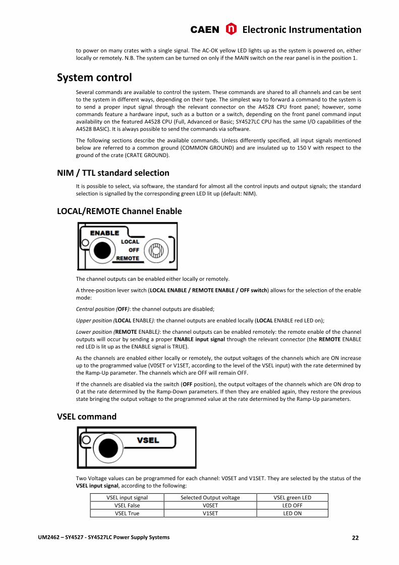
LOCAL/REMOTE Channel Enable
The channel outputs can be enabled either locally or remotely.
A three-position lever switch (LOCAL ENABLE / REMOTE ENABLE / OFF switch) allows for the selection of the enable mode:
Central position (OFF): the channel outputs are disabled;
Upper position (LOCAL ENABLE): the channel outputs are enabled locally (LOCAL ENABLE red LED on);
Lower position (REMOTE ENABLE): the channel outputs can be enabled remotely: the remote enable of the channel outputs will occur by sending a proper ENABLE input signal through the relevant connector (the REMOTE ENABLE red LED is lit up as the ENABLE signal is TRUE).
As the channels are enabled either locally or remotely, the output voltages of the channels which are ON increase up to the programmed value (V0SET or V1SET, according to the level of the VSEL input) with the rate determined by the Ramp-Up parameter. The channels which are OFF will remain OFF.
If the channels are disabled via the switch (OFF position), the output voltages of the channels which are ON drop to 0 at the rate determined by the Ramp-Down parameters. If then they are enabled again, they restore the previous state bringing the output voltage to the programmed value at the rate determined by the Ramp-Up parameters.
VSEL command
Two Voltage values can be programmed for each channel: V0SET and V1SET. They are selected by the status of the VSEL input signal, according to the following:
VSEL input signal Selected Output voltage VSEL green LED
VSEL False V0SET LED OFF
VSEL True V1SET LED ON

CAEN Electronic Instrumentation
UM2462 – SY4527 - SY4527LC Power Supply Systems 23
When channels are switched from V0SET to V1SET or vice versa, the output voltage drifts from one value to the other at the rate programmed for each channel (Ramp-Up or Ramp-Down parameter).
ISEL command
Two current limit values can be programmed for each channel: I0SET and I1SET. They are selected by the status of the ISEL input signal, according to the following:
ISEL input signal Selected Current limit ISEL green LED
ISEL False I0SET LED OFF
ISEL True I1SET LED ON
KILL command
The KILL input signal, sent through the relevant connector, allows to switch all the channels off at the maximum rate available, regardless of the Ramp-Down or other parameters.
The relevant green LED will be lit up as the KILL signal is True.
The KILL command can be also forwarded via software.
RESET command
The RESET command allows via the RESET input signal or the RESET push-button to reset the system CPU and, optionally, to reset the boards and to turn all the channels off. The action of the RESET command depends on the duration of the signal or of the press action:
RESET Signal: 100÷200 ms; only the CPU is reset and the whole system resumes its operation from the beginning. All the channels which are ON remain ON, channels which are OFF remain OFF
>1000 ms; also the boards are reset and the channels which are ON are dropped to zero at the maximum rate available and turned off
RESET push-button: “short” pressure; only the CPU is reset and the whole system resumes its operation from the beginning. All the channels which are ON remain ON, channels which are OFF remain OFF
“long” pressure; also the boards are reset and the channels which are ON are dropped to zero at the maximum rate available and turned off
After the RESET, the system will react so as to Power-On: if the Power-On option is enabled, each channel will be restored in the same condition it was before the RESET at the correct rate. If it is disabled, all the channels will be off, independently from the condition in which they were before the RESET.
N.B.: please note that any type of reset command must be enabled via software in the RESET FLAG Configuration register by tagging the relevant reset condition (see p.31).
The occurrence of RESET is also signaled by RESET FLAG output signal, according to the software user’s settings.

CAEN Electronic Instrumentation
UM2462 – SY4527 - SY4527LC Power Supply Systems 24
INTERLOCK command
The INTERLOCK command allows to switch off simultaneously all the channels, similarly to the KILL command.
The INTERLOCK command can be activated via the INTERLOCK input which acts as an open/closed contact. The selection of the contact position (open or closed) which will cause the INTERLOCK command is performed via the two-position INTERLOCK switch:
Upper position (OPEN): the channels are switched off as the INTERLOCK contact is open (the ground connection in the INTERLOCK input is removed);
Lower position (CLOSED): the channels are switched off as the INTERLOCK contact is closed (the INTERLOCK input is grounded).
The INTERLOCK condition of the system is signalled by the INTERLOCK green LED lit up.
In order to turn the channels on again, the user must remove the INTERLOCK condition. Any attempt to turn the channels on without removing the INTERLOCK condition will result unsuccessful.
HV SYNC
HVSYNC is the synchronisation clock for the Power Supply Units (RS485 standard, 1.25 MHz). It can work either as MASTER (MASTER red LED on), i.e. the synchronisation clock is internally generated and the HVSYNC connector works as output, or as SLAVE (red LED off), i.e. the synchronisation clock is externally generated and sent through the HV SYNC connector which works as input.
FAN
Three position switch; it allows to select Fan speed: High, Medium or Low. The red LEDs light up as the relevant speed is selected.
System status monitoring Several output signals and alarms are available to monitor the system status, as described in the following subsections. Please note that all output signals mentioned below, unless differently specified, are referred to a common ground (COMMON GROUND) and are insulated up to 150 V with respect to the ground of the crate (CRATE GROUND).

CAEN Electronic Instrumentation
UM2462 – SY4527 - SY4527LC Power Supply Systems 25
Over Current
The Over Current condition (OVC) occurs when at least one channel is in Over Current condition, i.e. at least one channel has reached the current limit. The Over Current condition is signalled by the OVC output signal True and the relevant red LED on. The system detects this condition as a fault and reacts according to the setting of the TRIP parameter, namely:
1) TRIP = 1000 (constant CURRENT mode)
If the Board has programmable current hardware protections, the output voltage is varied to keep the current below the programmed limit (I0SET or I1SET, according to the ISEL signal level). The channel behaves like a current generator. If the Board has fixed current hardware protections, the output current is permitted to exceed the ISET value; the channel behaves like a current generator only if the maximum current value is reached.
2) 0 < TRIP < 1000 (TRIP mode)
In this case, the channel behaves as in the constant CURRENT mode for a time equal to the finite value set as TRIP parameter, and then it is switched off according to the selected Power-Down option (KILL/RAMP). If the Kill option is selected, the channel will be switched off at the maximum rate available. If Ramp option is selected, the voltage will drop to zero at a rate determined by the value of the Ramp parameter programmed for that channel.
Under Voltage
The Under Voltage condition (UNV) occurs when at least one channel is in Under Voltage condition, i.e. when the actual value of the channel output voltage is lower than the programmed value. The Under Voltage condition is signalled by the UNV output signal True and the relevant red LED on.
Over Voltage
The Over Voltage condition occurs when at least one channel is in Over Voltage condition, i.e. when the actual value of the channel output voltage is higher than the programmed value. The Over Voltage condition is signalled by the OVV output signal True and the relevant red LED on.
Trip
The TRIP output signal is asserted True (and the relevant red LED is lit up) as the status of External Trip line 0 is HIGH (see p. 45); therefore the TRIP condition occurs as at least one channel, latched on External Trip line 0, has tripped and has been switched off due to an Over Current condition. To recover from this state, it is sufficient to turn the tripped channel On again or to execute a clear alarm command via software.

CAEN Electronic Instrumentation
UM2462 – SY4527 - SY4527LC Power Supply Systems 26
Reset flag
RST FLAG (RESET FLAG) output signal is TRUE (and relevant red LED on) after a RESET occurred, according to the user’s settings. The type of reset which asserts RST FLAG TRUE can actually be selected via software.
Check passed
CHK PASS (CHECK PASSED) output signal is True (and the relevant green LED on) when the initial check of the system is successful and the system is ready.
At normal operation, this signal is True and the relevant green LED is ON.
This output signal becomes false either as the Fan failure LED is lit up or as the Power failure LED is lit up. As the condition which caused the CHECK PASSED being FALSE is remove, the CHECK PASSED signal becomes true again.
GEN
GEN (GENERAL STATUS) output signal is True (and relevant red LED on) according to a logic combination of OVC, UNV, OVV and TRIP (status of External Trip line 0 is HIGH see also p.46). The logic combination of these conditions is defined by the user via software.
CH-ON
CH-ON (CHANNEL ON) output signal is True (and the relevant red LED on) as at least one board channel is ON (i.e. the channels are enabled and the POWER parameter of that channel is set to ON).
Over Temperature
Over Temperature condition occurs when there is at least one board at a temperature out of the range TMIN TMAX, where TMIN and TMAX are two parameters depending on the board type. As the Over Temperature condition is reached, the relevant front panel LED lights up.

CAEN Electronic Instrumentation
UM2462 – SY4527 - SY4527LC Power Supply Systems 27
Fan Failure
Fan Failure condition occurs when at least one of the fans of the system has stopped or is turning below 20% of normal speed.
As the Fan Failure condition is reached, the relevant front panel LED lights up.
Pwr Failure
Power Failure condition occurs when there is a fault in the voltage supplies at the +12 V, -12 V or +48 V level.
As the Power Failure condition is reached, the relevant front panel LED lights up.

CAEN Electronic Instrumentation
UM2462 – SY4527 - SY4527LC Power Supply Systems 28
6. Operating modes The System can be operated in one of the following ways:
Standalone operation
Remote operation via host computer by using TCP/IP protocol (OPC Server and CAEN HV Wrapper Library).
Standalone operation Standalone Operation is intended as the interactive control and monitoring of one SY4527 system by using one of these devices:
SY4527 SY4527LC
optional LCD Touchscreen (A4534 or A4537)
LCD + external keyboard and/or mouse (via USB port)
external PC (via Gigabit Ethernet)
external Tablet PC (via A4535 Wi-Fi dongle, connected to the USB port)
external PC (via Gigabit Ethernet)
external Tablet PC (via A4535 Wi-Fi dongle, connected to the USB port)
SY4527 crate
USB
+
Ethernet
Wi-F
i / U
SB
Tablet PC
Host PC
Mouse and/or External keyboard
Fig. 10 – Standalone Operation with LCD Touchscreen
Software Version
Description of the User Interface Software running on the SY4527 system refers to the:
Software Version x.yy.zz
A variation in the last two figures (.zz) of the software version refers to a debug operation; a variation in the two figures placed in the middle (.yy) refers to a feature upgrading of the software version; a variation in the first figure (x.) refers to a radical change of the software version.

CAEN Electronic Instrumentation
UM2462 – SY4527 - SY4527LC Power Supply Systems 29
Remote operation via Host Computer A newly released suite of applications guarantees CAEN power supplies' inter-operability between virtually all available computing environments and communication protocols.
OPC is an open interface based on the OLE/COM (now ActiveX) and DCOM technology; OPC offers "Plug&Play" connectivity between disparate control applications and hardware devices. The introduction of the OPC interface has caused the number of driver developments which hardware manufacturers implement for their components to be reduced to only one: the OPC server. On the other hand, OPC client applications (from any vendor) can communicate with the OPC server to exchange data and control commands in a standard way. Each device property is accessed via an OPC item. An OPC server creates OPC items on behalf of an OPC client. The client's OPC items are organized in OPC groups with a hierarchical structure.
OPC Client OPC ClientLAN
Ethernet
Router
Firewall
Internet
LabView on PC, Mac, Linux
OPC Client
Fig. 11 – Remote Operation via Host Computer
CAEN, in close collaboration with CERN (IT-CO group) has developed an OPC server which allows powerful, flexible and yet simple control of its power supply systems through TCP/IP by any OPC compliant client application. For further details please refer to the OPC Server for CAEN Power Supplies User’s Manual available at www.caen.it site.
A C library (CAENHVWrapper) providing the software developer an unified software interface for the control of all the CAEN Power Supply Systems is also available.

CAEN Electronic Instrumentation
UM2462 – SY4527 - SY4527LC Power Supply Systems 30
7. System Power-On The Power-ON of the system can be performed either locally or remotely, as described in the following subsections.
Preliminary check Before powering the system, check this:
SY4527 SY4527LC
Choose one of the set up’s described in Operating modes
The Primary Power Supply and the Booster Power Supply Units (if present) are inserted correctly in their relevant housings and fixed with the relevant screws;
The boards, after the required hardware settings, are plugged into the slots and fixed properly;
The power cord connects the crate to the mains correctly; see AC Input, p.19
Cabling has been performed according to the chosen hardware set-up;
Safety instructions, installation requirements and operation requirements have been complied.
Choose one of the set up’s described in Operating modes
The boards, after the required hardware settings, are plugged into the slots and fixed properly;
The power cord connects the crate to the mains correctly; see AC Input, p.19
Cabling has been performed according to the chosen hardware set-up;
Safety instructions, installation requirements and operation requirements have been complied.
Local Power-On To power-On the system locally follow this procedure:
SY4527 SY4527LC Set to ON (position 1) the back panel
MAIN switch
Turn the Power-On key, located on the panel of the A4531 Primary Power Supply, in the right position (ON LOCAL): the AC OK LED (yellow), located on the front panel of the A4531, lights up and the fan tray unit starts to work.
Following these operations, the following LEDs will be lit up on the front panels of the Primary Power Supply: AC-OK, VDD, +VCC, -VCC, VFAN, VPWR (see also A4531 Primary Power Supply Section).
After the initial check of the system, it is possible to access the system through the HiVoCS.
Set to ON the Main Switch.
After the initial check of the system, it is possible to access the system through the HiVoCS.
The system has a default address is 192.168.0.1 and the DHCP server configured to assign IP addresses on the network 192.168.0.0/255.255.255

CAEN Electronic Instrumentation
UM2462 – SY4527 - SY4527LC Power Supply Systems 31
Remote Power-On (SY4527) To power-On the system remotely follow this procedure:
Set to ON (position 1) the back panel Main switch, p.18.
Turn the Power-On key, on the front panel of the Primary Power Supply, in the left position (ON REMOTE), p.21;
Send a proper signal through the REMOTE IN input connector on the front panel of the Primary Power Supply: the OK LED (yellow), located on the front panel of the Primary Power Supply, will light up and the fan tray unit starts to work.
Following these operations, the following LEDs will be lit up on the front panels of the Primary Power Supply: AC-OK, VDD, +VCC, -VCC, VFAN, VPWR (see also A4531 Primary Power Supply Section).
After the initial check of the system, it is possible to access the system through the HiVoCS.
The system has a default address is 192.168.0.1 and the DHCP server configured to assign IP addresses on the network 192.168.0.0/255.255.255.
Configuration To configure the system, if the LCD Touchscreen color Display is not installed, connect it to your local network or use a Ethernet cable and connect it directly to your PC Ethernet port (see also SY4527 Quickstart Guide). Wait until the PC has received an IP address after which you can connect to the HiVoCS and configure the network you want, by following the instructions in DHCP Server chapter of this manual (p.38). open a web browser and type: http://192.168.0.1 and enter user id and password. The system default is: User ID: admin Password: admin You should change your password as soon as possible to prevent other people from altering system settings without your consent.
If case of forgotten IP address of the system or the admin username and password, in order to restore the default setting, connect an USB keyboard to the USB connector of the CPU panel and use key combination CTRL+ALT+DEL; the system will produce a "buzz" sound, after the last buzz, wait for about 15 sec, then reboot the system, default settings will be restored.
System Reset Flag Configuration The SYx527 system allows to configure different reset conditions, in order to set the system behavior after reset signals. Such settings can be performed by accessing via software to the ResFlagCfg 16 bit register; such register can be set and monitored via CAEN OPC Server, CAEN HV Wrapper Library and CAENGECO2020 Control Software Tool.
The ResFlagCfg bits are as follows:
bit Reset condition
0 1 = backplane reset due to CPU failure: the system cannot recover after a A4528 CPU error; the board section backplane is reset
1 always set to 1
2 1 = backplane reset due to front panel reset input signal (pushbutton or logic level; see p. 23)
3 1 = CPU reset due to front panel reset input signal (pushbutton or logic level; see p. 23)
4 ÷ 5 always set to 1
6 15 always set to 0
This register allows also to enable the relevant reset condition. If the corresponding bit is set to 1, it is enabled; if it is 0, it is disabled. For example, if the bit 3 (front panel reset) is 0, a signal sent through the front panel connector does not reset the CPU.
Reset signal must be compliant to the specifications described at p. 23.
If more than one reset types are selected in the ResFlagCfg 16 bit register, the system will be reset according to the occurrence of any of them.

CAEN Electronic Instrumentation
UM2462 – SY4527 - SY4527LC Power Supply Systems 32
8. HiVoCS The HiVoCS is the web tool that allows to manage the SY4527 Connection status and system/board upgrade.
System Log-in First of all, launch the web browser, then type the Power Supply System IP address into the address bar; the following log-in window will open:
Fig. 12 – HiVoCS Log in window
Three access levels are foreseen: admin, user, guest
factory setting allows to access the System under the following profile:
User ID Password Level
admin admin Admin
The Admin level allows to access all the settings of the system, of the boards and of the channels; moreover it allows to upgrade the system software and the board firmware. Moreover the Admin level allows to:
Create new lower level (User and Guest) users (up to 15 users);
Remove lower level users;
Change the admin password;
Execute the Format command, which restores the factory-set users, with the related passwords (and deletes all the other ones).
Two lower level are foreseen:
“User” level can turn on/off the channels and change their own passwords, but cannot perform any setting.
“Guest” level can only monitor the system configuration and channel status and change their own passwords.
Once logged as “admin”, the next window will show, in the upper toolbar, two thumbnails:
Upgrade
Main Menu

CAEN Electronic Instrumentation
UM2462 – SY4527 - SY4527LC Power Supply Systems 33
Main Menu By selecting “Main Menu” the configurator will offer the following options:
Fig. 13 – HiVoCS Main menu
The side bar shows the System features (type, version, s/n, etc.)
Crate Map
Crate Map is entered from the Main menu and opens the Crate Map Window showing what types of boards are inserted into the crate and in which slot they are plugged into.
Fig. 14 – HiVoCS Crate Map
CAEN Electronic Instrumentation
UM2462 – SY4527 - SY4527LC Power Supply Systems 34
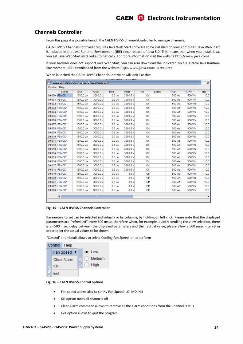
Channels Controller
From this page it is possible launch the CAEN HVPSS ChannelsController to manage channels.
CAEN HVPSS ChannelsController requires Java Web Start software to be installed on your computer. Java Web Start is included in the Java Runtime Environment (JRE) since release of Java 5.0. This means that when you install Java, you get Java Web Start installed automatically. For more information visit the website http://www.java.com/
If your browser does not support Java Web Start, you can also download the indicated zip file. Oracle Java Runtime
Environment (JRE) downloaded from the websitehttp://www.java.com/ is required.
When launched the CAEN HVPSS ChannelsController will look like this:
Fig. 15 – CAEN HVPSS Channels Controller
Parameters to set can be selected individually or by columns, by holding on left click. Please note that the displayed parameters are “refreshed” every 500 msec, therefore when, for example, quickly scrolling the view selection, there is a <500 msec delay between the displayed parameters and their actual value; please allow a 500 msec interval in order to let the actual values to be shown.
“Control” thumbnail allows to select Cooling Fan Speed, or to perform
Fig. 16 – CAEN HVPSS Control options
Fan speed allows also to set Hv Fan Speed (LO, MD, HI)
Kill option turns all channels off
Clear Alarm command allows to remove all the alarm conditions from the Channel Status
Exit option allows to quit the program

CAEN Electronic Instrumentation
UM2462 – SY4527 - SY4527LC Power Supply Systems 35
Sessions
The Session option shows the parameters of the connected Users sessions.
Fig. 17 – HiVoCS session parameters
Documentation
The documentation option allows to download the available technical manuals and guides.
Setting Menu
Fig. 18 – Setting Menu
The Setting Menu has the following options:
Users Management
Change password
Networking
DHCP Server
Remote Assistance
CAEN Electronic Instrumentation
UM2462 – SY4527 - SY4527LC Power Supply Systems 36
System Time
License Manager
EPICS
Reboot
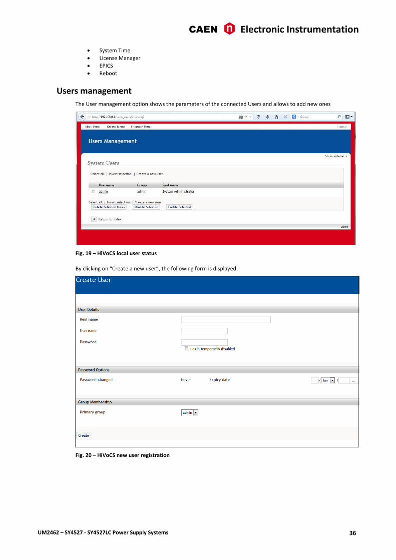
Users management
The User management option shows the parameters of the connected Users and allows to add new ones
Fig. 19 – HiVoCS local user status
By clicking on “Create a new user”, the following form is displayed:
Fig. 20 – HiVoCS new user registration

CAEN Electronic Instrumentation
UM2462 – SY4527 - SY4527LC Power Supply Systems 37
Change password
Change password option will open a simple form box that allows to update the User’s password.
Fig. 21 – HiVoCS Change password form
Networking
The Networking option allows to configure the SY4527 System for network connection.
The Ethernet connector provided with the system is a 10/100baseT connector and can be used to interface the SY4527 system to an Ethernet LAN. This allows the system control via an external standard PC connected to a TCP/IP network and running a web browser.
Before establishing a connection to a TCP/IP network, a specific IP Address, IP Net Mask must be assigned by the local Network Administrator to the SY4527 System.
If the User needs to connect to the SY4527 system from outside the local network, a Gateway address has to be specified in the TCP/IP settings.
Fig. 22 – HiVoCS network status

CAEN Electronic Instrumentation
UM2462 – SY4527 - SY4527LC Power Supply Systems 38
DHCP Server
DHCP Server allows to assign IP addresses to the Client’s PC connected to the network, through the following form box:
Fig. 23 – HiVoCS DHCP Server form

CAEN Electronic Instrumentation
UM2462 – SY4527 - SY4527LC Power Supply Systems 39
Remote Assistance
The Remote Assistance option allows to enable or disable the remote assistance. When Remote Assistance is enabled, CAEN personnel can access the system for remote maintenance intervention; in order to do this the system must also be connected to an externally accessible network.
Fig. 24 – HiVoCS remote assistance
System time
The System time option allows to set the time and date of the SY4527
Fig. 25 – HiVoCS System time setting
License Manager
The License Manager has two options:
System Add On allows to activate the optional “enhancement activation code”
o CAEN HV Control Software functionality enhancement is available upon purchase. If you have purchased the “Control software functionality enhancement activation code” (ordering code WSW4536XAAAA), prior to installation of the CAEN HV Control Software, you have to go to “Main menu” > License Manager, then type the “enhancement activation code” you received
CAEN Electronic Instrumentation
UM2462 – SY4527 - SY4527LC Power Supply Systems 40
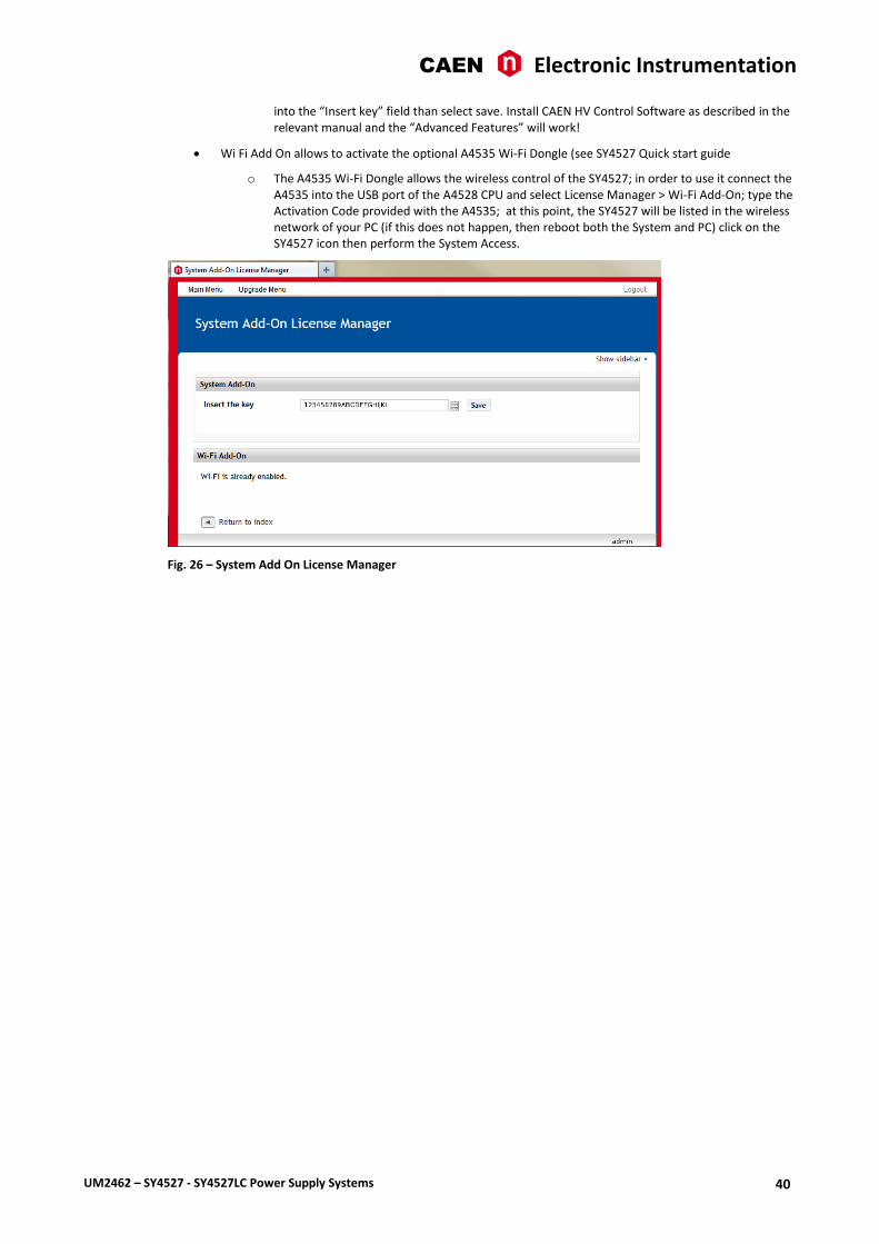
into the “Insert key” field than select save. Install CAEN HV Control Software as described in the relevant manual and the “Advanced Features” will work!
Wi Fi Add On allows to activate the optional A4535 Wi-Fi Dongle (see SY4527 Quick start guide
o The A4535 Wi-Fi Dongle allows the wireless control of the SY4527; in order to use it connect the A4535 into the USB port of the A4528 CPU and select License Manager > Wi-Fi Add-On; type the Activation Code provided with the A4535; at this point, the SY4527 will be listed in the wireless network of your PC (if this does not happen, then reboot both the System and PC) click on the SY4527 icon then perform the System Access.
Fig. 26 – System Add On License Manager

CAEN Electronic Instrumentation
UM2462 – SY4527 - SY4527LC Power Supply Systems 41
EPICS
EPICS (Experimental Physics and Industrial Control System) is a set of software tools and applications which provide a software infrastructure for use in building distributed control systems, widely used to control experimental Physics and industrial electronics.
CAEN Universal Multichannel Power Supply System integrates an EPICS Service that provides access to a Process Variable using the Channel Access Protocol. Process Variable is a named piece of data associated with the system (e.g. status, readback, setpoint, parameter).
Client software (EPICS Channel Access Client), which requests access to a Process Variable, runs on the Host PC and is connected to the system via TCP/IP.
More information about EPICS and a list of available client applications can be found at:
http://www.aps.anl.gov/epics/.
By selecting the EPICS option in the Setting menu, it is possible to:
Enable EPICS Service at Boot automatically.
Set the name of service (e.g. the system hostname). This term will be used as a prefix for the Process Variable, so as to be unique in case of multiple systems connected.
To apply changes click on Save button. Service name will be changed at the next restart of the EPICS Service, in case it was already running.
Note: when EPICS Service is enabled, it is not provided authentication for the access to the Process Variables, therefore the network administrator would implement appropriate access rules.
Fig. 27 – EPICS Service configuration menu
The relevant buttons allow to:
show the Process Variables published
enable/disable/restart EPICS Service
o Note: If any HV card is inserted or removed from the system, you should restart the EPICS Service to update the Process Variable.

CAEN Electronic Instrumentation
UM2462 – SY4527 - SY4527LC Power Supply Systems 42
In the Process Variable page, it is possible to see:
The “Records” option lists all Process Variables available. Items can be filtered with the System/Slot entries select, or located with the search input box.
For each record is indicated the type and the read/write operations that are allowed.
The “Control Fields” option lists the fields that are available, grouped by Record Type.
All records have fields: VAL (default), DESC and DTYP.
Fig. 28 – EPICS Process Variables
System Reboot
This option allows to immediately reboot the system. All currently logged in users will be disconnected and all services will be re-started.
Upgrade menu The Upgrade menu allows to update the firmware version of both the SY4527 system and the boards plugged into the system slots or into remote crates, handled via branch controllers.
Fig. 29 – HiVoCS Upgrade menu

CAEN Electronic Instrumentation
UM2462 – SY4527 - SY4527LC Power Supply Systems 43
The HiVoCS Upgrade option allows to upgrade the HiVoCS web tool (i.e. Add new features, bug-fix etc.). In order to do this:
o click the relevant icon
o browse the file to load, which has the format: sy4527-5527-HiVoCS-x.y.z-date.bin
o click <upload>
o wait for the “update done!” message
o restart the system for the upgrades to become effective
Fig. 30 – Upgrade “Update done” message
The HV Control Firmware Upgrade option allows to upgrade the firmware that handle the system activities (board control, channels control, OPC Server access etc.). In order to do this:
o click the relevant icon,
o browse the file to load, which has the format: sy4527-5527-HVFw- x.y.z-date.bin
o click <upload>
o wait for the “update done!” message
o restart the system for the upgrades to become effective
o wait for buzz sound to communicate successful upgrade
this may take up to some minutes: do not turn off the system meanwhile!
The Board Upgrade option allows to upgrade the firmware of the board in the selected slot. In order to do this:
o click the relevant icon
o select the slot that hosts the board to upgrade
o browse the file to load, which has the format: A1535-689.301 (example of A1535 board)
o click <upgrade>
The Remote Board Upgrade option allows to upgrade the firmware of a remote board handled by a branch controller housed in a Syx527 slot. In order to do this:
o click the relevant icon
o select the slot that hosts the branch controller
o select the remote crate number
o select the remote slot number
o browse the file to load, which has the format: A3100-558.204 (example of A3100 board)
o click <upgrade>
Upgrade trouble-shooting
If failure occurs while HV Control Firmware Upgrade process is running, it is possible to repeat the procedure in the following way:

CAEN Electronic Instrumentation
UM2462 – SY4527 - SY4527LC Power Supply Systems 44
Turn Off the system
Remove the CPU
Place SW1 switch of the CPU on BKP position (left); see figure below
Plug the CPU into the system
Turn On the system
Repeat the HV Control Firmware Upgrade procedure
Turn Off the system
Remove the CPU
Place SW1 switch of the CPU on STD position (right)
Fig. 31 – SW1 location on A4528 CPU mother board

CAEN Electronic Instrumentation
UM2462 – SY4527 - SY4527LC Power Supply Systems 45
9. Secure shell connection It is possible to connect with the SYx527 via SSH protocol; in order to do this, “Remote assistance” (see p. 39) must be enabled. At this point:
Launch a terminal emulator (such as Tera Term VT)
Connect to SYx527 with the following settings:
o Connection: TCP/IP
o Service: SSH
o TCP port #: 22
o Host: SYx527 IP address
The terminal emulator will ask user ID and password;
entering
o Username: admin
o Password: admin
The terminal shell will allow “transparent mode” access
entering
o Username: telnet
o Password: oldstuff
The terminal shell will display the channel parameters list; use the “arrows” to select the parameter fields; numerical parameters are changed by typing the new value and confirmed via “enter”, “boolean” parameters (such as Pw) are toggled via “space bar”.
Fig. 32 – Telnet user connection

CAEN Electronic Instrumentation
UM2462 – SY4527 - SY4527LC Power Supply Systems 46
10. Trip handling If a channel trips due to Over Current, it can be useful to have the possibility of letting automatically other channels (which are not in Over Current) trip; this feature is implemented on most of the PS boards. Please check also the Board User’s Manual, since some boards provide decimal TripInt and TripExt parameters, while other boards provide hexadecimal TripInt and TripExt.
Internal Trip A Power Supply Board features a number of “virtual” trip lines usually equal to half the number of its channels, so a 12 channel board features an internal 6-line Trip Bus. The channels communicate with each other through this bus: a channel can be allowed to either propagate or sense (or both propagate and sense) the trip status through one or more trip lines. This feature is achieved by writing a 2N-bit word (Dec. 0÷2
2N-1; maximum 16 lines) in the relevant
channel’s TRIPINT parameter (see CAEN HV Control Software and CAENGECO2020 User’s manual), where N is the number of the board’s Internal Trip Bus lines. Bits [0;N-1] allow the channel to sense the trip status from the corresponding lines when set to one; in the same way, bits [N;2N-1] allow the channel to propagate the trip status over the Trip Bus: bit N on line 0 and so on.
For example we consider a 12 channel board with a 6-line trip bus (TRIPINT[n]: 0÷4095): if TRIPINT[0] is set to 64 (CH0 propagates the TRIP on line 0), TRIPINT[3] is set to 65, TRIPINT[4] is set to 65 (CH3 and CH4 both propagate and sense the TRIP on line 0) and TRIPINT[5] is set to 1 (CH5 senses the TRIP on line 0), then:
CH3 trips whenever either CH0 or CH4 trips
CH4 trips whenever either CH0 or CH3 trips
CH5 trips whenever either CH0 or CH3 trips or CH4 trips
This configuration is shown below
INTERNAL TRIP BUS
Propagate Sense
Line 5 Line 4 Line 3 Line 2 Line 1 Line 0 Line 5 Line 4 Line 3 Line 2 Line 1 Line 0
TRIPINT0 0 0 0 0 0 1 0 0 0 0 0 0
TRIPINT1 0 0 0 0 0 0 0 0 0 0 0 0
TRIPINT2 0 0 0 0 0 0 0 0 0 0 0 0
TRIPINT3 0 0 0 0 0 1 0 0 0 0 0 1
TRIPINT4 0 0 0 0 0 1 0 0 0 0 0 1
TRIPINT5 0 0 0 0 0 0 0 0 0 0 0 1
TRIPINT6 0 0 0 0 0 0 0 0 0 0 0 0
TRIPINT7 0 0 0 0 0 0 0 0 0 0 0 0
TRIPINT8 0 0 0 0 0 0 0 0 0 0 0 0
TRIPINT9 0 0 0 0 0 0 0 0 0 0 0 0
TRIPINT10 0 0 0 0 0 0 0 0 0 0 0 0
TRIPINT11 0 0 0 0 0 0 0 0 0 0 0 0
External Trip The External Trip shares most of its features with the internal one. The number of lines is four, fixed for any kind of board, so the TRIPEXT parameter must be set in the 0÷255 range. Bits [0;3] allow the channel to sense the trip status from the corresponding lines when set to one; in the same way, bits [4;7] allow the channel to propagate the trip status over the trip bus of the system mainframe: bit 4 on line 0 and so on. Line 0 status of the trip bus of the system mainframe is exported by the TRIP out signal of the CPU (see Table 3).

CAEN Tools for Discovery
n
Electronic Instrumentation
UM2462 – SY4527 - SY4527LC Power Supply Systems 47
CAEN SpA is acknowledged as the only company in the world providing a complete range of High/Low Voltage Power Supply systems and Front-End/Data Acquisition modules which meet IEEE Standards for Nuclear and Particle Physics. Extensive Research and Development capabilities have allowed CAEN SpA to play an important, long term role in this field. Our activities have always been at the forefront of technology, thanks to years of intensive collaborations with the most important Research Centres of the world. Our products appeal to a wide range of customers including engineers, scientists and technical professionals who all trust them to help achieve their goals faster and more effectively.
CAEN S.p.A. CAEN GmbH CAEN Technologies, Inc.
Via Vetraia, 11 Klingenstraße 108 1140 Bay Street - Suite 2 C
55049 Viareggio D-42651 Solingen - Germany Staten Island, NY 10305
Italy Phone +49 (0)212 254 4077 USA
Tel. +39.0584.388.398 Fax +49 (0)212 25 44079 Tel. +1.718.981.0401
Fax +39.0584.388.959 Mobile +49 (0)151 16 548 484 Fax +1.718.556.9185
[email protected] [email protected] [email protected]
www.caen.it www.caen-de.com www.caentechnologies.com
CAEN Tools for Discovery
Electronic Instrumentation
UM2462 - SY4527 - SY4527LC Power Supply Systems rev. 12 - 9 June 2015
00118-10-4527M-MUTX
Copyright © CAEN SpA. All rights reserved. Information in this publication supersedes all earlier versions. Specifications subject to change without notice.