Embed Size (px)
Citation preview
®
TOOLING COMPONENTS
®
®
Since 1926, Brauer has been providing industry with the finest engineered products, experttechnical support, on time deliveries and unparalleled customer service. Our brands are nowrecognised world-wide as products of the highest quality, and the breadth of our product portfolioprovides our demanding customers with a tooling solution for a wide variety of problems.
Our team of highly talented engineers is backed by the latest computer aided design facilitiesincluding three dimensional feature based parametric solid modelling. Manufacturing is carried out inour modern, well equipped factory accredited with ISO 9001 certification and situated in MiltonKeynes, some 40 miles north of London.
At Brauer, we continue to be motivated by working with our customers in providing innovativesolutions for their particular tooling requirements. These working partnerships, built by many years ofunparalleled customer service, will ensure that Brauer branded tooling, and automation products, willremain at the forefront of their markets.
To view the complete tooling portfolio manufactured by the Brauer companies, please consult ourWeb Site at www.Brauer.co.uk.
For further details of any Brauer Productcontact
HMC BRAUER LIMITEDDAWSON ROAD, MOUNT FARM, MILTON KEYNES, ENGLAND MK1 1JP
TEL: 00 44 (0)1908-374022 FAX: 00 44 (0)1908-641628email: [email protected] Web: www.brauer.co.uk
© HMC Brauer Ltd 2004No part of this publication may be reproduced in any form (including photocopying or storing in any medium by
electronic means) without the written permission of HMC Brauer Ltd.
HMC-Brauer Limited reserve the right to change the design or specification of the products shownin this catalogue without prior notification.
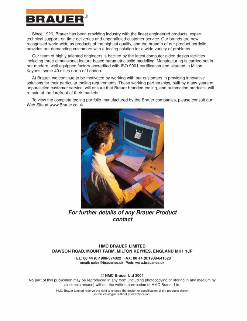
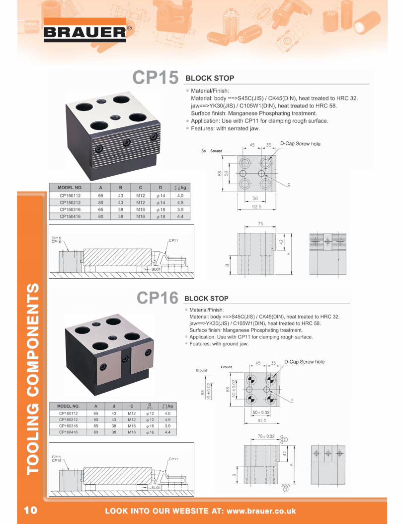
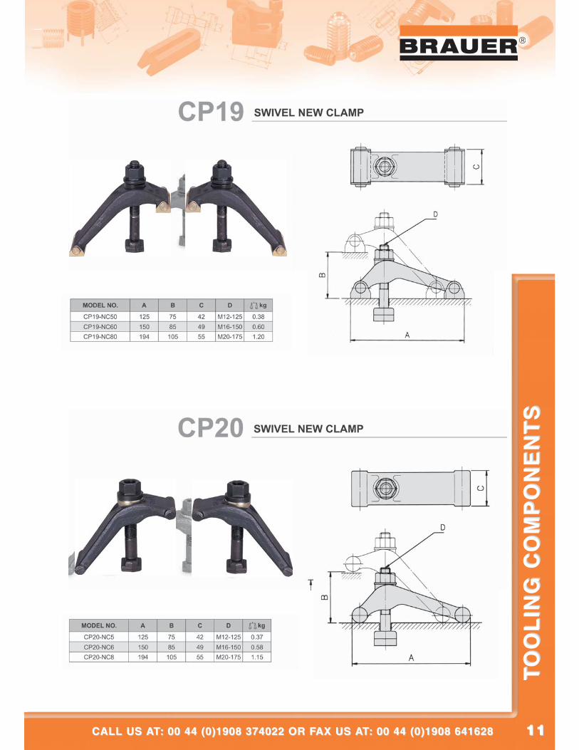
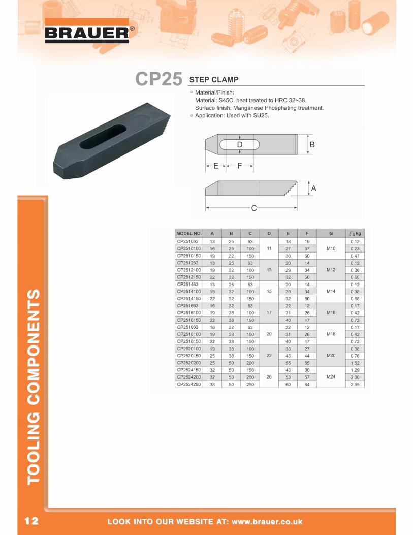
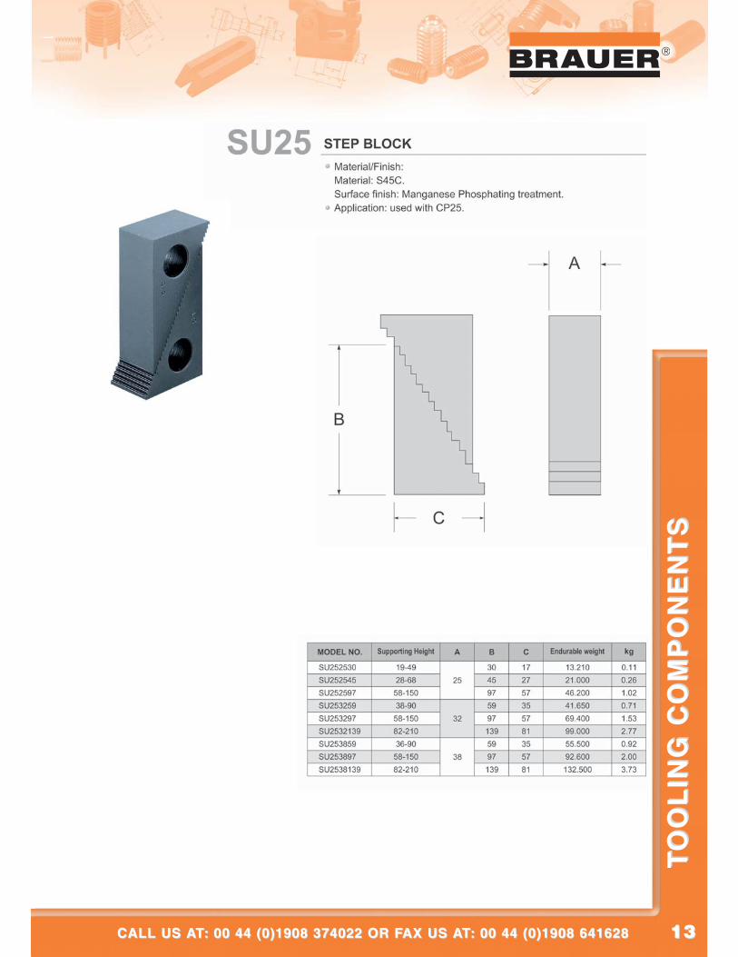
MACHINE CLAMPSMACHINE CLAMPSCP01 U Clamp 44CP03 Goose Neck 44CP05 Plane-Clamp 55CP06 Tapped End Clamp Strap 55CP07 Slotted End Clamp Strap 66CP08 Swing Clamp 66CP11 Free Jaw Vise 77CP12 & CP13 Adjustable Side Clamp 7 - 87 - 8CP14 Pivoting Side Clamp 99CP15 & CP16 Block Stop 1010CP19 & CP20 Swivel New Clamp 1111CP25 Step Clamp 1212CP35 & CP36 Replacement Hard-Jaw 1313“Actima” clamping device 1414“Arness” clamping device 1515Quick-acting Clamps 1616Taper Clamping Units Form A 1717Taper Clamping Units Form A + L
with extra length for made to order forms 1818Taper Clamping Units Form B 1919Hook Clamps 2020Cam Ram Clamps
CR4000 & CR5000 (clockwise) 2121CR4000 & CR4000 (anti-clockwise) 2121
Cam Swing ClampsCS300 & CS800 (clockwise) 2222CS300A & CS800A (anti-clockwise) 2222
Cam Swing ClampsCS1200 (clockwise) & CS1200A (anti-clockwise) 2323
Cam Swing Height Block Assemblies 2323Cam Push Clamps - CP1500, CP2000 & CP3000 2424Cam Push Clamps - CP1500L, CP2000L & CP3000L 2525Cam Push/Cam Pull Clamps 2626Swing Clamp Assemblies - 1016-08 & 1016-10 2727Swing Clamp Assemblies - 1016-12 & 1016-16 2828Swing Clamps - 1015-08, 1015-10, 1015-12 & 1015-16 2929Quick-Lock Pins 3030
MACHINE AND JIG COMPONENTSMACHINE AND JIG COMPONENTSLateral Spring Plungers 3232Eccentric Bushes 3333Spring Plungers smooth surface plastic 3434Spring Plungers smooth surface,
steel parts in stainless steel 3434Spring Plungers with recess and pressure pin 3535Spring Plungers with hexagon socket
and pressure pin 36 - 3736 - 37Spring Plungers with hexagon socket and ball 3838Spring Plungers with recess and ball 3939Spring Plungers with LONG-LOK thread lock 4040Spring Plungers Long-Lok secured
with hexagon socket and ball 4141
CALL US AT: 00 44 (0)1908 374022 OR FAX US AT: 00 44 (0)1908 641628CALL US AT: 00 44 (0)1908 374022 OR FAX US AT: 00 44 (0)1908 641628
TO
OL
ING
CO
MP
ON
EN
TS
TO
OL
ING
CO
MP
ON
EN
TS
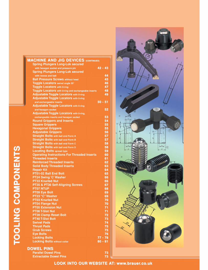
MACHINE AND JIG DEVICES MACHINE AND JIG DEVICES (CONTINUED)(CONTINUED)
Spring Plungers Long-Lok securedwith hexagon socket and pressure pin 42 - 4342 - 43
Spring Plungers Long-Lok securedwith recess and ball 4444
Ball Pressure Screws without head 4545Toggle Locators swivel angle 20° 4646Toggle Locators with 0-ring 4747Toggle Locators with 0-ring and exchangeable inserts 4848Adjustable Toggle Locators with 0-ring 4949Adjustable Toggle Locators with 0-ring
and exchangeable inserts 50 - 5150 - 51Adjustable Toggle Locators with 0-ring
and hexagon socket 5252Adjustable Toggle Locators with 0-ring,
exchangeable inserts and hexagon socket 5353Round Grippers and Inserts 5454Square Grippers 5555Hexagonal Grippers 5555Adjustable Grippers 5656Straight Bolts with ball end Form A 5757Straight Bolts with ball end Form B 5757Straight Bolts with ball end Form C 5858Straight Bolts with ball end Form D 5858Locating Bolts spread type 5959Operating Instructions For Threaded Inserts 6060Threaded Inserts 6161Reinforced Threaded Inserts 6262Solid Body Threaded Inserts 6363Repair Kit 6464PT01-02 Ball End Bolt 6565PT24 Swing ‘C’ Washer 6666PT33 Knurled Nut 6666PT35 & PT36 Self-Aligning Screws 6767PT07 NTUP 6868PT09 Eye Bolt 6969PT23 “C” Washer 6969PT03 Knurled Nut 7070PT04 Flange Nut 7070PT05 Extension Nut 7171PT06 T-Slot Nut 7171PT39 Clamp Reset Bolt 7272PT40 T-Slot Bolt 7373Swivel Pads 7474Thrust Pads 7575Grub Screws 7575Eye Bolts 7676Locking Bolts 77 - 7877 - 78Locking Bolts without collar 80 - 8180 - 81
DOWEL PINSDOWEL PINSParallel Dowel Pins 7373Extractable Dowel Pins 7373
LOOK INTO OUR WEBSITE AT: www.brauer.co.uk LOOK INTO OUR WEBSITE AT: www.brauer.co.uk
TO
OL
ING
CO
MP
ON
EN
TS
TO
OL
ING
CO
MP
ON
EN
TS
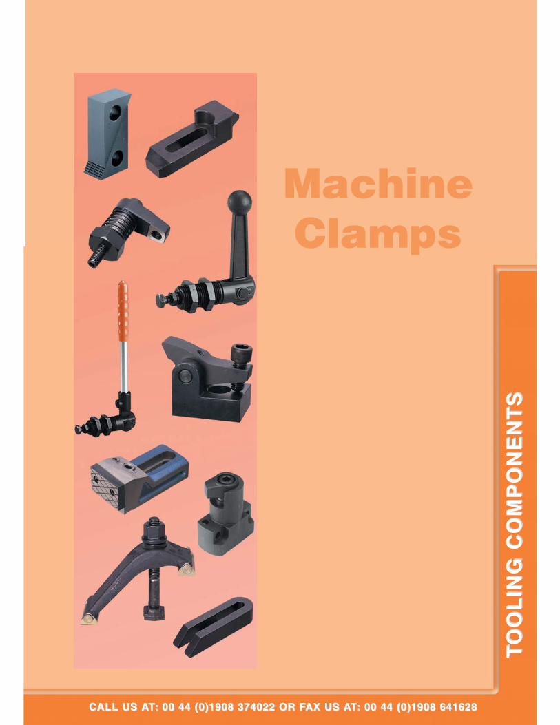
MachineClamps
CALL US AT: 00 44 (0)1908 374022 OR FAX US AT: 00 44 (0)1908 641628CALL US AT: 00 44 (0)1908 374022 OR FAX US AT: 00 44 (0)1908 641628
TO
OL
ING
CO
MP
ON
EN
TS
TO
OL
ING
CO
MP
ON
EN
TS
®
LOOK INTO OUR WEBSITE AT: www.brauer.co.uk LOOK INTO OUR WEBSITE AT: www.brauer.co.uk
TO
OL
ING
CO
MP
ON
EN
TS
TO
OL
ING
CO
MP
ON
EN
TS
44
55
®
CALL US AT: 00 44 (0)1908 374022 OR FAX US AT: 00 44 (0)1908 641628CALL US AT: 00 44 (0)1908 374022 OR FAX US AT: 00 44 (0)1908 641628
TO
OL
ING
CO
MP
ON
EN
TS
TO
OL
ING
CO
MP
ON
EN
TS
®
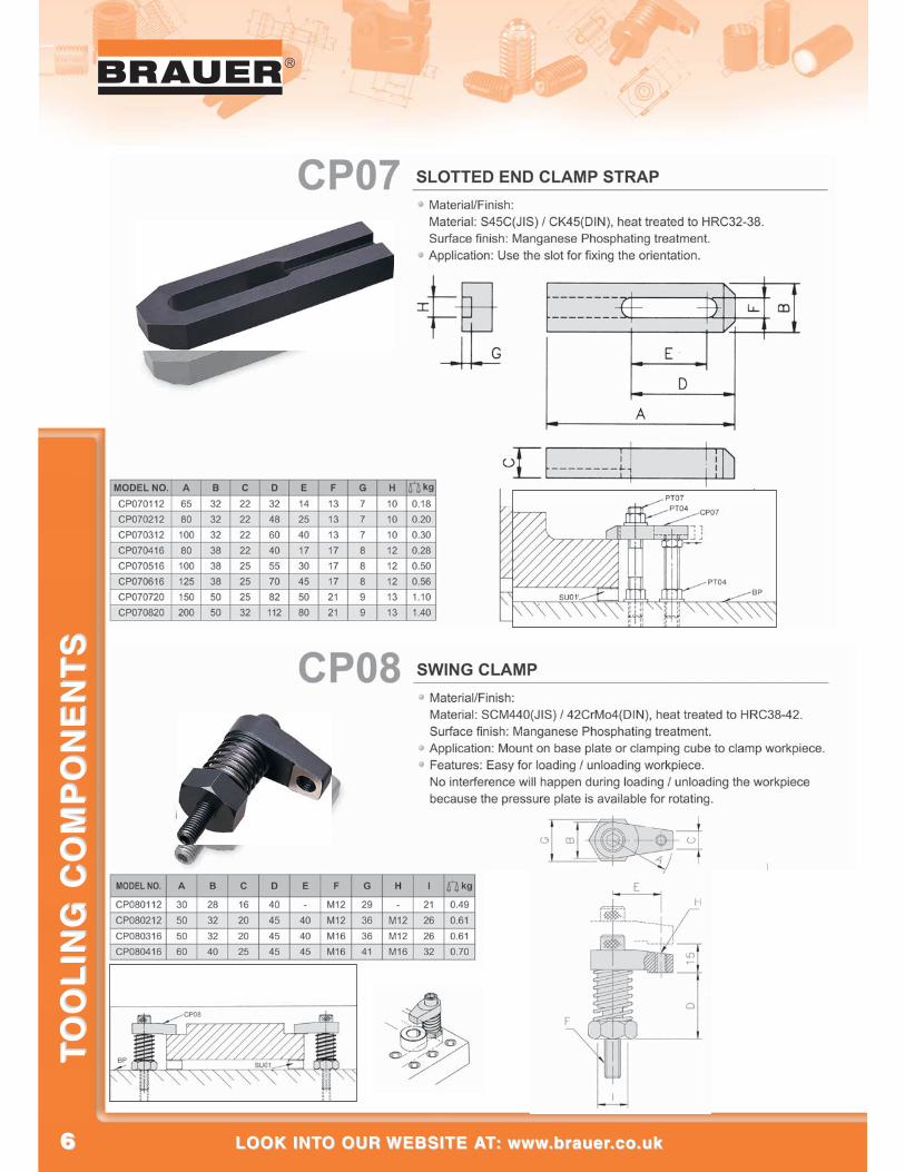
66
®
LOOK INTO OUR WEBSITE AT: www.brauer.co.uk LOOK INTO OUR WEBSITE AT: www.brauer.co.uk
TO
OL
ING
CO
MP
ON
EN
TS
TO
OL
ING
CO
MP
ON
EN
TS
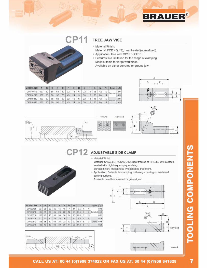
77
®
CALL US AT: 00 44 (0)1908 374022 OR FAX US AT: 00 44 (0)1908 641628CALL US AT: 00 44 (0)1908 374022 OR FAX US AT: 00 44 (0)1908 641628
TO
OL
ING
CO
MP
ON
EN
TS
TO
OL
ING
CO
MP
ON
EN
TS
®
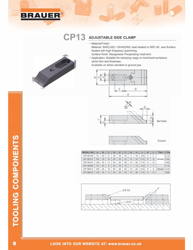
88
®
LOOK INTO OUR WEBSITE AT: www.brauer.co.uk LOOK INTO OUR WEBSITE AT: www.brauer.co.uk
TO
OL
ING
CO
MP
ON
EN
TS
TO
OL
ING
CO
MP
ON
EN
TS
99
®
CALL US AT: 00 44 (0)1908 374022 OR FAX US AT: 00 44 (0)1908 641628CALL US AT: 00 44 (0)1908 374022 OR FAX US AT: 00 44 (0)1908 641628
TO
OL
ING
CO
MP
ON
EN
TS
TO
OL
ING
CO
MP
ON
EN
TS
®
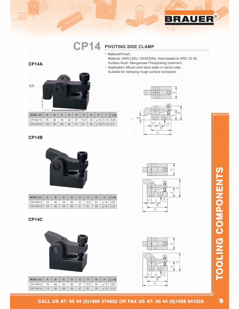
CP14A
CP14B
CP14C
1010
®
LOOK INTO OUR WEBSITE AT: www.brauer.co.uk LOOK INTO OUR WEBSITE AT: www.brauer.co.uk
TO
OL
ING
CO
MP
ON
EN
TS
TO
OL
ING
CO
MP
ON
EN
TS
1111
®
CALL US AT: 00 44 (0)1908 374022 OR FAX US AT: 00 44 (0)1908 641628CALL US AT: 00 44 (0)1908 374022 OR FAX US AT: 00 44 (0)1908 641628
TO
OL
ING
CO
MP
ON
EN
TS
TO
OL
ING
CO
MP
ON
EN
TS
1212
®
LOOK INTO OUR WEBSITE AT: www.brauer.co.uk LOOK INTO OUR WEBSITE AT: www.brauer.co.uk
TO
OL
ING
CO
MP
ON
EN
TS
TO
OL
ING
CO
MP
ON
EN
TS
1313
®
CALL US AT: 00 44 (0)1908 374022 OR FAX US AT: 00 44 (0)1908 641628CALL US AT: 00 44 (0)1908 374022 OR FAX US AT: 00 44 (0)1908 641628
TO
OL
ING
CO
MP
ON
EN
TS
TO
OL
ING
CO
MP
ON
EN
TS
1414
®
LOOK INTO OUR WEBSITE AT: www.brauer.co.uk LOOK INTO OUR WEBSITE AT: www.brauer.co.uk
TO
OL
ING
CO
MP
ON
EN
TS
TO
OL
ING
CO
MP
ON
EN
TS
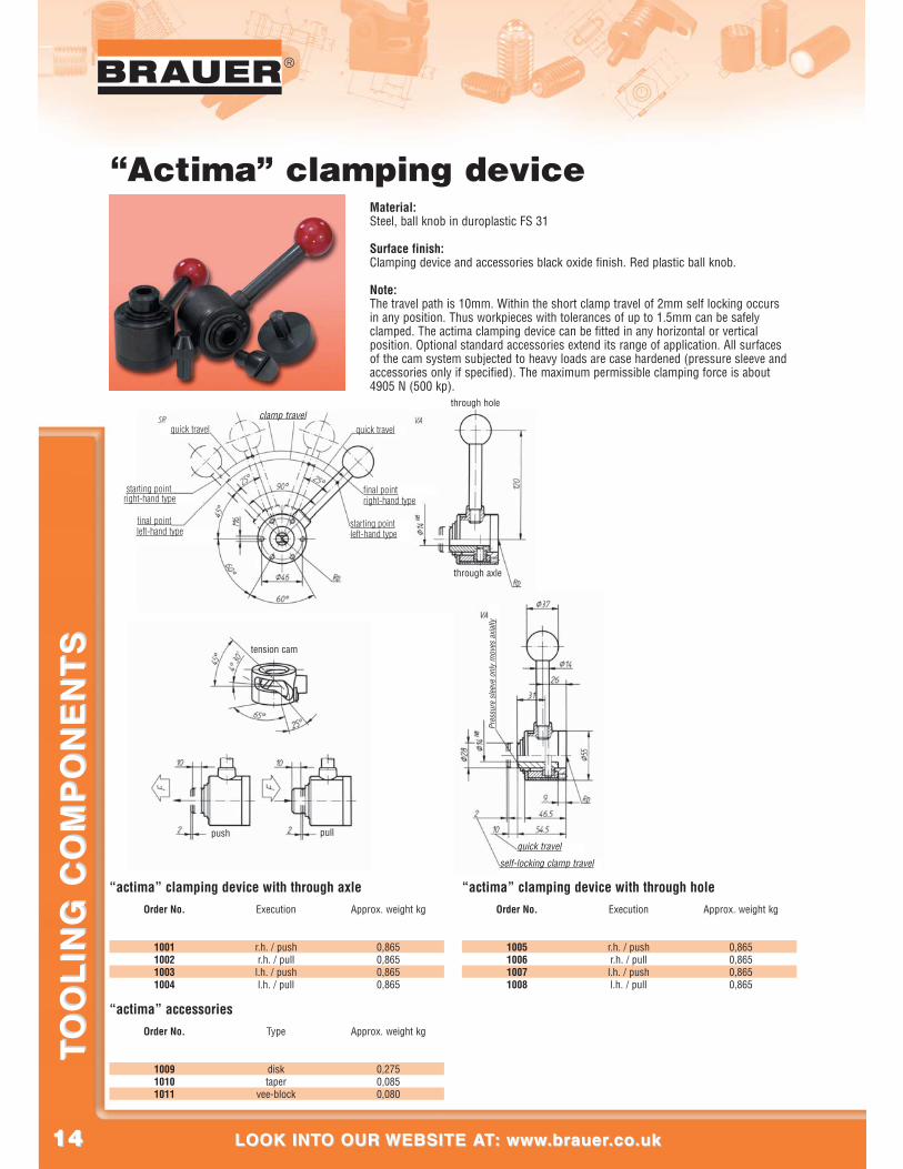
“Actima” clamping device
“actima” clamping device with through axleOrder No.
1001100210031004
r.h. / pushr.h. / pulll.h. / pushl.h. / pull
0,8650,8650,8650,865
Execution Approx. weight kg
“actima” clamping device with through holeOrder No.
1005100610071008
r.h. / pushr.h. / pulll.h. / pushl.h. / pull
0,8650,8650,8650,865
Execution Approx. weight kg
“actima” accessoriesOrder No.
100910101011
disktaper
vee-block
0,2750,0850,080
Type Approx. weight kg
clamp travelquick travelquick travel
starting point
final point
right-hand type
starting pointleft-hand type
final pointright-hand type
left-hand type
through hole
through axle
tension cam
push pull
Pres
sure
sle
eve
only
mov
es a
xial
ly
quick travel
self-locking clamp travel
Material:Steel, ball knob in duroplastic FS 31
Surface finish:Clamping device and accessories black oxide finish. Red plastic ball knob.
Note:The travel path is 10mm. Within the short clamp travel of 2mm self locking occursin any position. Thus workpieces with tolerances of up to 1.5mm can be safelyclamped. The actima clamping device can be fitted in any horizontal or verticalposition. Optional standard accessories extend its range of application. All surfacesof the cam system subjected to heavy loads are case hardened (pressure sleeve andaccessories only if specified). The maximum permissible clamping force is about4905 N (500 kp).
1515
®
CALL US AT: 00 44 (0)1908 374022 OR FAX US AT: 00 44 (0)1908 641628CALL US AT: 00 44 (0)1908 374022 OR FAX US AT: 00 44 (0)1908 641628
TO
OL
ING
CO
MP
ON
EN
TS
TO
OL
ING
CO
MP
ON
EN
TS
®
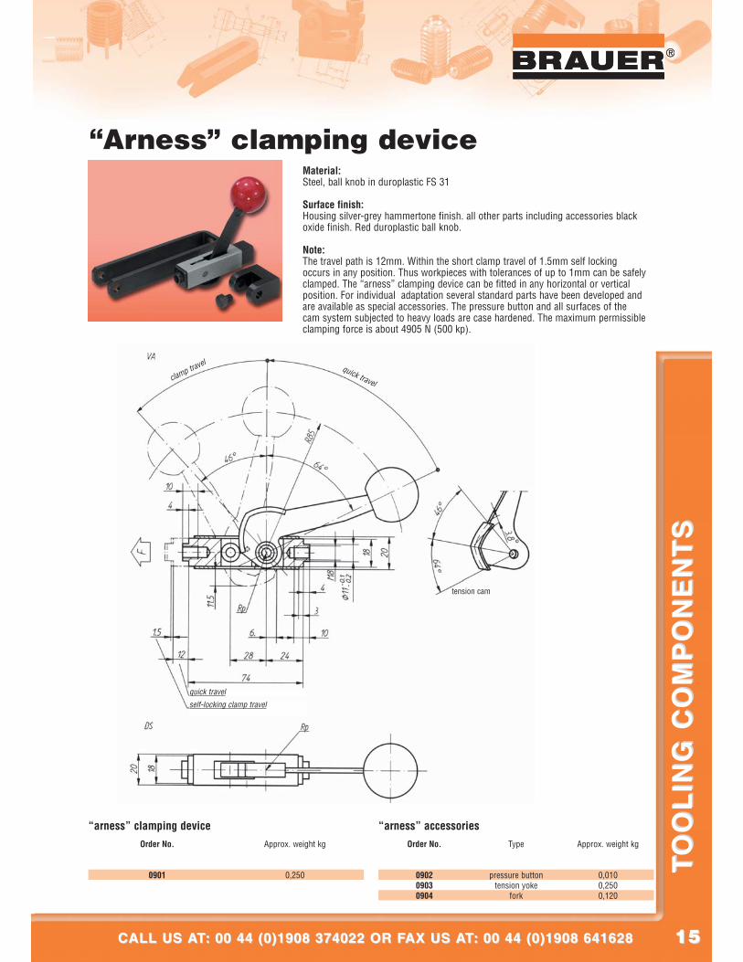
“Arness” clamping device Material:Steel, ball knob in duroplastic FS 31
Surface finish:Housing silver-grey hammertone finish. all other parts including accessories blackoxide finish. Red duroplastic ball knob.
Note:The travel path is 12mm. Within the short clamp travel of 1.5mm self lockingoccurs in any position. Thus workpieces with tolerances of up to 1mm can be safelyclamped. The “arness” clamping device can be fitted in any horizontal or verticalposition. For individual adaptation several standard parts have been developed andare available as special accessories. The pressure button and all surfaces of thecam system subjected to heavy loads are case hardened. The maximum permissibleclamping force is about 4905 N (500 kp).
“arness” clamping deviceOrder No.
0901 0,250
Approx. weight kg
“arness” accessoriesOrder No.
090209030904
pressure buttontension yoke
fork
0,0100,2500,120
Type Approx. weight kg
clamp travelquick travel
tension cam
quick travel
self-locking clamp travel
1616
®
LOOK INTO OUR WEBSITE AT: www.brauer.co.uk LOOK INTO OUR WEBSITE AT: www.brauer.co.uk
TO
OL
ING
CO
MP
ON
EN
TS
TO
OL
ING
CO
MP
ON
EN
TS
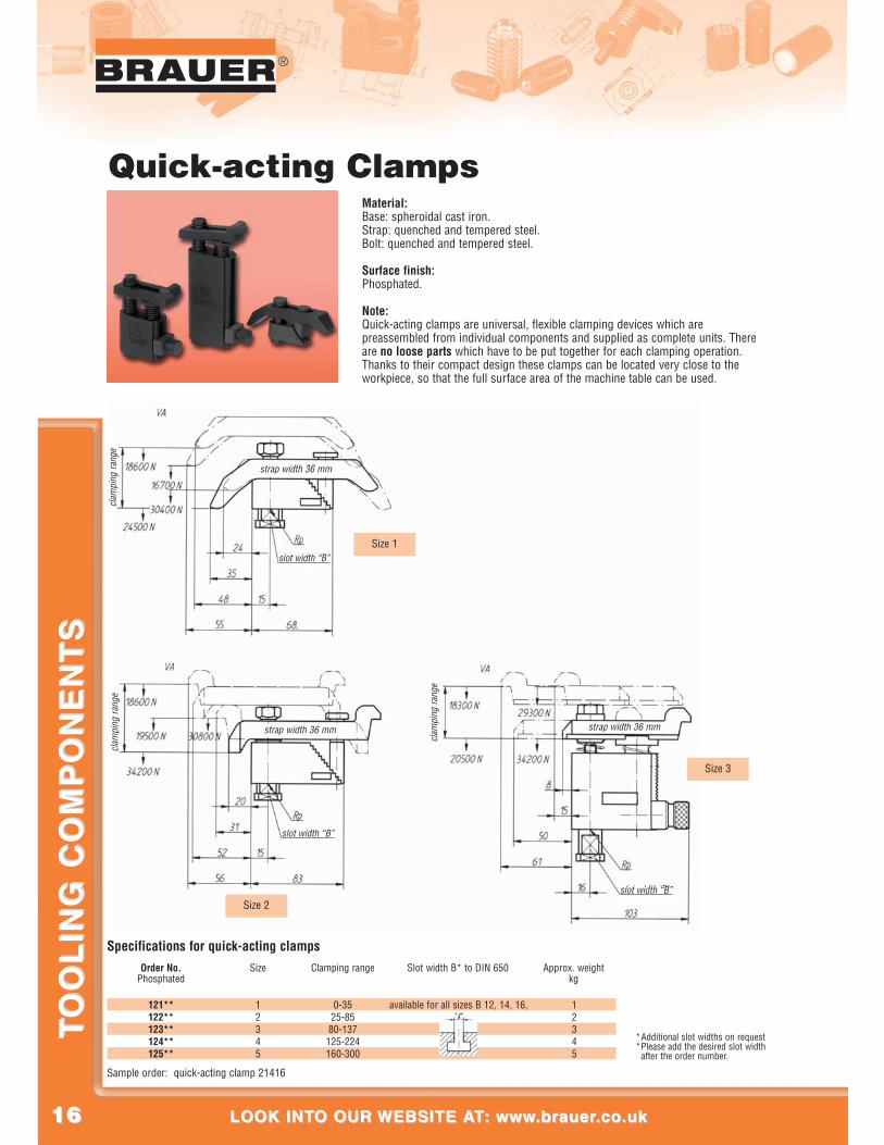
Quick-acting ClampsMaterial:Base: spheroidal cast iron.Strap: quenched and tempered steel.Bolt: quenched and tempered steel.
Surface finish:Phosphated.
Note:Quick-acting clamps are universal, flexible clamping devices which arepreassembled from individual components and supplied as complete units. Thereare no loose parts which have to be put together for each clamping operation.Thanks to their compact design these clamps can be located very close to theworkpiece, so that the full surface area of the machine table can be used.
Sample order: quick-acting clamp 21416
*Additional slot widths on request*Please add the desired slot width
after the order number.
Specifications for quick-acting clampsOrder No.
PhosphatedSize Clamping range Slot width B* to DIN 650
121**122**123**124**125**
12345
Approx. weightkg
12345
0-3525-85
80-137125-224160-300
available for all sizes B 12, 14, 16,18
clam
ping
rang
e
strap width 36 mm
slot width “B”
clam
ping
rang
e
strap width 36 mm
slot width “B”
clam
ping
rang
e
strap width 36 mm
slot width “B”
Size 1
Size 2
Size 3
1717
®
CALL US AT: 00 44 (0)1908 374022 OR FAX US AT: 00 44 (0)1908 641628CALL US AT: 00 44 (0)1908 374022 OR FAX US AT: 00 44 (0)1908 641628
TO
OL
ING
CO
MP
ON
EN
TS
TO
OL
ING
CO
MP
ON
EN
TS
®
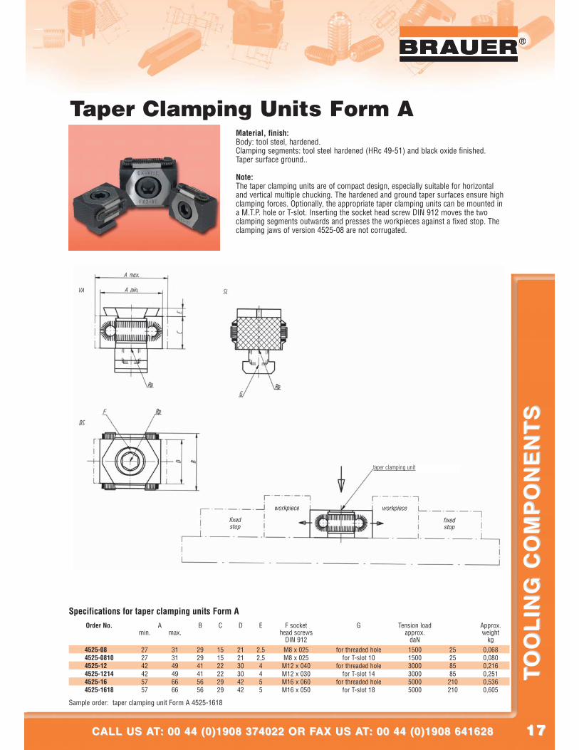
Taper Clamping Units Form AMaterial, finish:Body: tool steel, hardened.Clamping segments: tool steel hardened (HRc 49-51) and black oxide finished.Taper surface ground..
Note:The taper clamping units are of compact design, especially suitable for horizontaland vertical multiple chucking. The hardened and ground taper surfaces ensure highclamping forces. Optionally, the appropriate taper clamping units can be mounted ina M.T.P. hole or T-slot. Inserting the socket head screw DIN 912 moves the twoclamping segments outwards and presses the workpieces against a fixed stop. Theclamping jaws of version 4525-08 are not corrugated.
Sample order: taper clamping unit Form A 4525-1618
Specifications for taper clamping units Form AOrder No.
4525-08004525-08104525-12004525-12144525-16004525-1618
Amin. max.
B C D E
272742425757
313149496666
292941415656
151522222929
212130304242
2,52,54455
M8 x 025M8 x 025M12 x 040M12 x 030M16 x 060M16 x 050
for threaded holefor T-slot 10
for threaded holefor T-slot 14
for threaded holefor T-slot 18
0,0680,0800,2160,2510,5360,605
25258585210210
150015003000300050005000
F sockethead screws
DIN 912
Approx.weight
kg
Tension loadapprox.
daN
G
fixedstop
workpiece workpiece
fixedstop
taper clamping unit

1818
®
LOOK INTO OUR WEBSITE AT: www.brauer.co.uk LOOK INTO OUR WEBSITE AT: www.brauer.co.uk
TO
OL
ING
CO
MP
ON
EN
TS
TO
OL
ING
CO
MP
ON
EN
TS
Taper Clamping Units Form A + L with extra length for made to order formsMaterial, finish:
Body: tool steel, hardened.Clamping segments: tool steel (HRc 30), black oxide finished.Taper surface ground.Clamping segments with worked-in shape or other hardness values available onrequest.
Note:The special feature of the taper clamping units “Form A + L” lies in the added lengthper clamping jaw of 3mm for versions 4526-08 and 3mm for versions 4526-12.This extra length allows form adjusted to the workpiece geometry to be worked in(see illustration). The clamping jaws of version 4526-08 are not corrugated.
Sample order: taper clamping unit Form A+L 4525-12
Specifications for taper clamping units Form A+LOrder No.
4526-08004526-08104526-12004526-1214
Amin. max.
B C D E
33335252
37375959
29294141
15152222
21213030
2,52,544
M8 x 025M8 x 025M12 x 040M12 x 030
for threaded holefor T-slot 10
for threaded holefor T-slot 14
0,0840,0960,2760,303
25258585
1500150030003000
F sockethead screws
DIN 912
Approx.weight
kg
Tension loadapprox.
daN
G
taper clamping unit
workpiece
block stopper
base plate
hydraulic/pneumatic cylinder
1919
®
CALL US AT: 00 44 (0)1908 374022 OR FAX US AT: 00 44 (0)1908 641628CALL US AT: 00 44 (0)1908 374022 OR FAX US AT: 00 44 (0)1908 641628
TO
OL
ING
CO
MP
ON
EN
TS
TO
OL
ING
CO
MP
ON
EN
TS
®
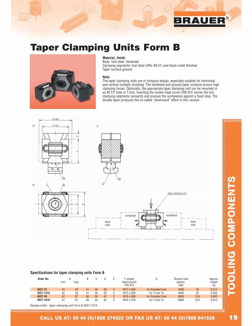
Taper Clamping Units Form BMaterial, finish:Body: tool steel, hardened.Clamping segments: tool steel (HRc 49-51) and black oxide finished.Taper surface ground.
Note:The taper clamping units are of compact design, especially suitable for horizontaland vertical multiple chucking. The hardened and ground taper surfaces ensure highclamping forces. Optionally, the appropriate taper clamping unit can be mounted inan M.T.P. hole or T-slot. Inserting the socket head screw DIN 912 moves the twoclamping segments outwards and presses the workpieces against a fixed stop. Thedouble taper produces the so-called “downward” effect in this version.
Sample order: taper clamping unit Form B 4527-1214
Specifications for taper clamping units Form BOrder No.
4527-12004527-12144527-16004527-1618
Amin. max.
B C D E
42425757
49496767
41415656
36365050
30304242
5555
M12 x 060M12 x 050M16 x 080M16 x 070
for threaded holefor T-slot 14
for threaded holefor T-slot 18
0,3140,3530,8430,912
2525210210
4000400060006000
F sockethead screws
DIN 912
Approx.weight
kg
Tension loadapprox.
daN
G
fixedstop
workpiece workpiece
fixedstop
taper clamping unit
2020
®
LOOK INTO OUR WEBSITE AT: www.brauer.co.uk LOOK INTO OUR WEBSITE AT: www.brauer.co.uk
TO
OL
ING
CO
MP
ON
EN
TS
TO
OL
ING
CO
MP
ON
EN
TS
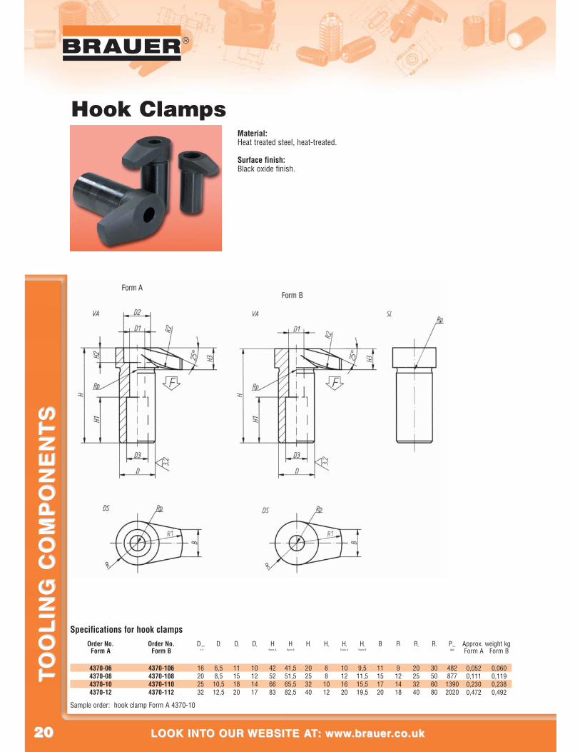
Hook Clamps Material:Heat treated steel, heat-treated.
Surface finish:Black oxide finish.
Sample order: hook clamp Form A 4370-10
Specifications for hook clampsOrder No.
Form AOrder No.
Form B
4370-064370-084370-104370-12
4370-1064370-1084370-1104370-112
16202532
6,58,5
10,512,5
11151820
10121417
42526683
41,551,565,582,5
20253240
681012
10121620
9,511,515,519,5
11151720
9121418
20253240
30506080
48287713902020
D-0,02
-0,10
D1 D2 D3 HForm A
HForm B
H1 H2 H3
Form A
H3
Form B
B R R1 R2 Pmax.
daN
0,052 0,0600,111 0,1190,230 0,2380,472 0,492
Approx. weight kgForm A Form B
2121
®
CALL US AT: 00 44 (0)1908 374022 OR FAX US AT: 00 44 (0)1908 641628CALL US AT: 00 44 (0)1908 374022 OR FAX US AT: 00 44 (0)1908 641628
TO
OL
ING
CO
MP
ON
EN
TS
TO
OL
ING
CO
MP
ON
EN
TS
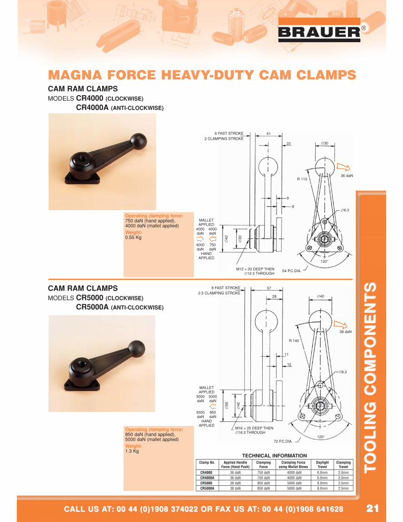
MAGNA FORCE HEAVY-DUTY CAM CLAMPS
Clamp No. Applied Handle Clamping Clamping Force Daylight ClampingForce (Hand Push) Force using Mallet Blows Travel Travel
CR5000A 38 daN 850 daN 5000 daN 8.0mm 2.5mm
CR4000A 36 daN 750 daN 4000 daN 6.0mm 2.0mmCR4000A 36 daN 750 daN 4000 daN 6.0mm 2.0mmCR5000A 38 daN 850 daN 5000 daN 8.0mm 2.5mm
TECHNICAL INFORMATION
CAM RAM CLAMPSMODELS CR4000 (CLOCKWISE)
CR4000A (ANTI-CLOCKWISE)
CAM RAM CLAMPSMODELS CR5000 (CLOCKWISE)
CR5000A (ANTI-CLOCKWISE)
MALLETAPPLIED
HANDAPPLIED
M12 × 20 DEEP THEN∅12.3 THROUGH
6 FAST STROKE2 CLAMPING STROKE
54 P.C.DIA.
4000daN
4000daN
4000daN
750daN
∅42
41
22
9
8
36 daN
120°
∅30
∅6.3
R 110
∅30
MALLETAPPLIED
HANDAPPLIED
M16 × 25 DEEP THEN∅16.3 THROUGH
8 FAST STROKE2.5 CLAMPING STROKE
72 P.C.DIA.
5000daN
5000daN
5000daN
850daN
∅56
57
28
11
10
38 daN
120°
∅40
∅8.3
R 140
∅42
Operating clamping force:850 daN (hand applied),5000 daN (mallet applied)Weight:1.3 Kg
Operating clamping force:750 daN (hand applied),4000 daN (mallet applied)Weight:0.55 Kg
2222
®
LOOK INTO OUR WEBSITE AT: www.brauer.co.uk LOOK INTO OUR WEBSITE AT: www.brauer.co.uk
TO
OL
ING
CO
MP
ON
EN
TS
TO
OL
ING
CO
MP
ON
EN
TS
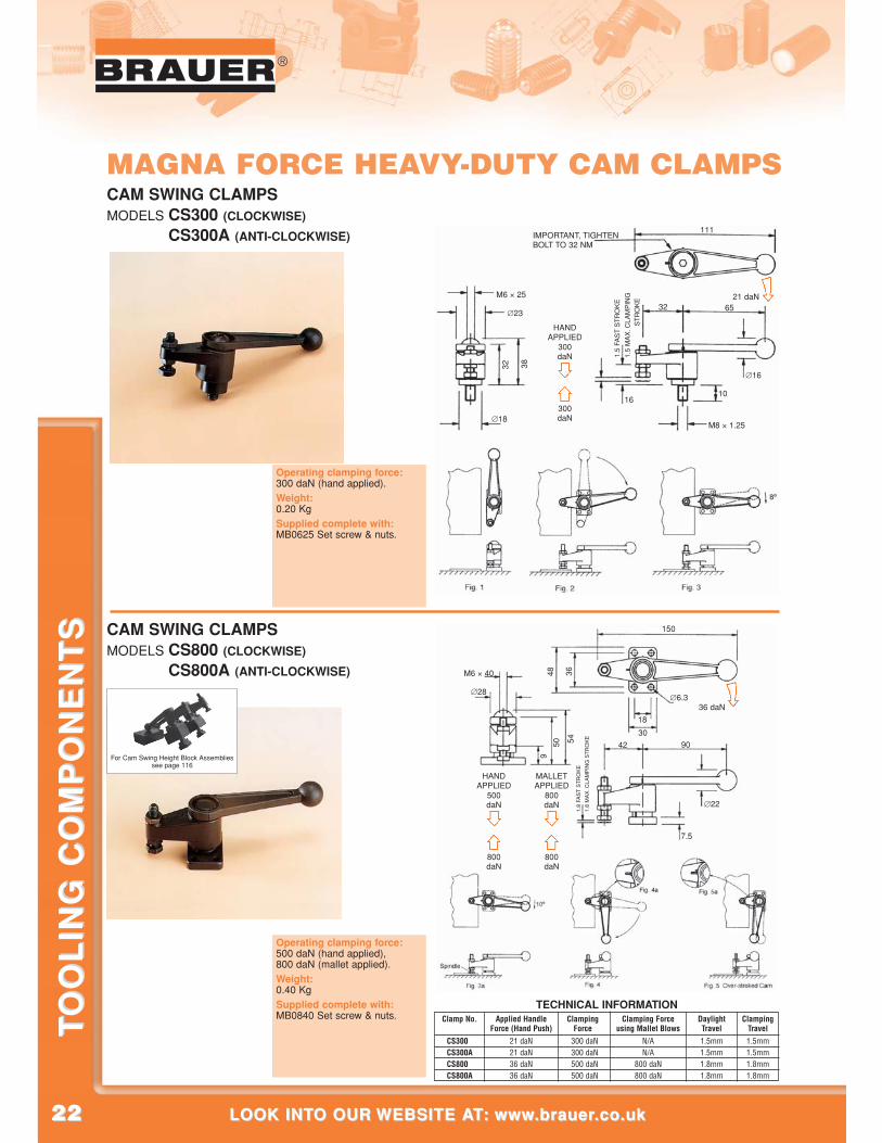
MAGNA FORCE HEAVY-DUTY CAM CLAMPSCAM SWING CLAMPSMODELS CS300 (CLOCKWISE)
CS300A (ANTI-CLOCKWISE)
CAM SWING CLAMPSMODELS CS800 (CLOCKWISE)
CS800A (ANTI-CLOCKWISE)
Operating clamping force: 300 daN (hand applied).Weight:0.20 KgSupplied complete with: MB0625 Set screw & nuts.
Operating clamping force: 500 daN (hand applied), 800 daN (mallet applied).Weight:0.40 KgSupplied complete with: MB0840 Set screw & nuts. Clamp No. Applied Handle Clamping Clamping Force Daylight Clamping
Force (Hand Push) Force using Mallet Blows Travel TravelCS300A 21 daN 300 daN N/A 1.5mm 1.5mmCS300A 21 daN 300 daN N/A 1.5mm 1.5mmCS800A 36 daN 500 daN 800 daN 1.8mm 1.8mmCS800A 36 daN 500 daN 800 daN 1.8mm 1.8mm
TECHNICAL INFORMATION
M6 × 40
∅22
∅28∅6.3
150
18
42
7.5
30
3648
9050
9
541.
8 FA
ST
ST
RO
KE
1.8
MA
X. C
LAM
PIN
G S
TR
OK
E
HANDAPPLIED
M6 × 25
IMPORTANT, TIGHTENBOLT TO 32 NM
∅18
300daN
300daN
∅23
111
32
1610
21 daN65
M8 × 1.25
∅16
32 38
1.5
FAS
T S
TR
OK
E
1.5
MA
X. C
LAM
PIN
GS
TR
OK
E
HANDAPPLIED
500daN
800daN
MALLETAPPLIED
800daN
800daN
36 daN
For Cam Swing Height Block Assembliessee page 116
2323
®
CALL US AT: 00 44 (0)1908 374022 OR FAX US AT: 00 44 (0)1908 641628CALL US AT: 00 44 (0)1908 374022 OR FAX US AT: 00 44 (0)1908 641628
TO
OL
ING
CO
MP
ON
EN
TS
TO
OL
ING
CO
MP
ON
EN
TS
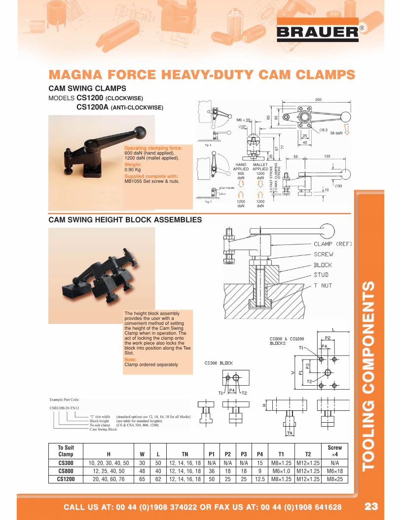
MAGNA FORCE HEAVY-DUTY CAM CLAMPSCAM SWING CLAMPSMODELS CS1200 (CLOCKWISE)
CS1200A (ANTI-CLOCKWISE)
HANDAPPLIED
M6 × 55
∅30
∅8.3
600daN
1200daN
MALLETAPPLIED
1200daN
1200daN
∅37
200
25
55
10
38 daN
40
5065
120
67
26
77
2.5
FAS
T S
TR
OK
E
2.0
MA
X. C
LAM
PIN
GS
TR
OK
E
Operating clamping force: 600 daN (hand applied), 1200 daN (mallet applied).Weight:0.90 KgSupplied complete with: MB1055 Set screw & nuts.
CAM SWING HEIGHT BLOCK ASSEMBLIES
To Suit ScrewClamp H W L TN P1 P2 P3 P4 T1 T2 ×4CS300 10, 20, 30, 40, 50 30 50 12, 14, 16, 18 N/A N/A N/A 15 M8×1.25 M12×1.25 N/ACS800 12, 25, 40, 50 48 40 12, 14, 16, 18 36 18 18 9 M6×1.0 M12×1.25 M6×18CS1200 20, 40, 60, 76 65 62 12, 14, 16, 18 50 25 25 12.5 M8×1.25 M12×1.25 M8×25
The height block assemblyprovides the user with aconvenient method of settingthe height of the Cam SwingClamp when in operation. Theact of locking the clamp ontothe work piece also locks theblock into position along the TeeSlot.Note:Clamp ordered separately
2424
®
LOOK INTO OUR WEBSITE AT: www.brauer.co.uk LOOK INTO OUR WEBSITE AT: www.brauer.co.uk
TO
OL
ING
CO
MP
ON
EN
TS
TO
OL
ING
CO
MP
ON
EN
TS
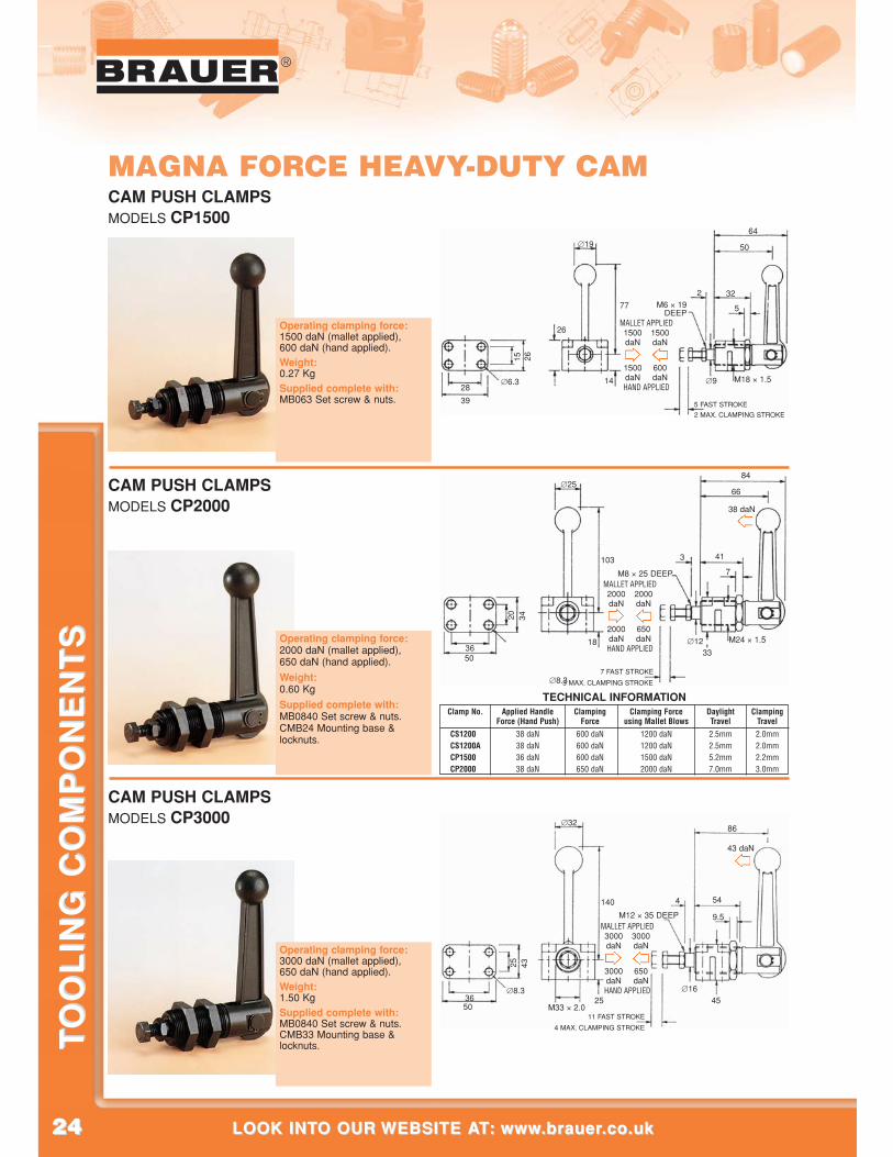
MAGNA FORCE HEAVY-DUTY CAM
CAM PUSH CLAMPSMODELS CP3000
CAM PUSH CLAMPSMODELS CP2000
∅32
∅1645
54
9.5
∅8.3
25
86
43 daN
M12 × 35 DEEP
M33 × 2.05036
4
25
140
43
11 FAST STROKE
4 MAX. CLAMPING STROKE
∅25
∅12
41
7
∅8.3
20
33
66
M8 × 25 DEEP
M24 × 1.5
84
5036
3
18
103
34
7 FAST STROKE
3 MAX. CLAMPING STROKE
MALLET APPLIED
HAND APPLIED
2000daN
2000daN
2000daN
650daN
Clamp No. Applied Handle Clamping Clamping Force Daylight ClampingForce (Hand Push) Force using Mallet Blows Travel Travel
CS1200A 38 daN 600 daN 1200 daN 2.5mm 2.0mmCS1200A 38 daN 600 daN 1200 daN 2.5mm 2.0mmCP1500A 36 daN 600 daN 1500 daN 5.2mm 2.2mmCP2000A 38 daN 650 daN 2000 daN 7.0mm 3.0mm
TECHNICAL INFORMATION
38 daN
MALLET APPLIED
HAND APPLIED
3000daN
3000daN
3000daN
650daN
CAM PUSH CLAMPSMODELS CP1500
∅19
∅9
32
5
∅6.3
15
26
50
M6 × 19DEEP
M18 × 1.5
64
39
28
2
14
77
26
MALLET APPLIED
HAND APPLIED
1500daN
1500daN
1500daN
600daN
5 FAST STROKE
2 MAX. CLAMPING STROKE
Operating clamping force: 2000 daN (mallet applied), 650 daN (hand applied).
Weight:0.60 Kg
Supplied complete with: MB0840 Set screw & nuts. CMB24 Mounting base &locknuts.
Operating clamping force: 3000 daN (mallet applied), 650 daN (hand applied).Weight:1.50 KgSupplied complete with: MB0840 Set screw & nuts. CMB33 Mounting base &locknuts.
Operating clamping force: 1500 daN (mallet applied), 600 daN (hand applied).Weight:0.27 KgSupplied complete with: MB063 Set screw & nuts.
2525
®
CALL US AT: 00 44 (0)1908 374022 OR FAX US AT: 00 44 (0)1908 641628CALL US AT: 00 44 (0)1908 374022 OR FAX US AT: 00 44 (0)1908 641628
TO
OL
ING
CO
MP
ON
EN
TS
TO
OL
ING
CO
MP
ON
EN
TS
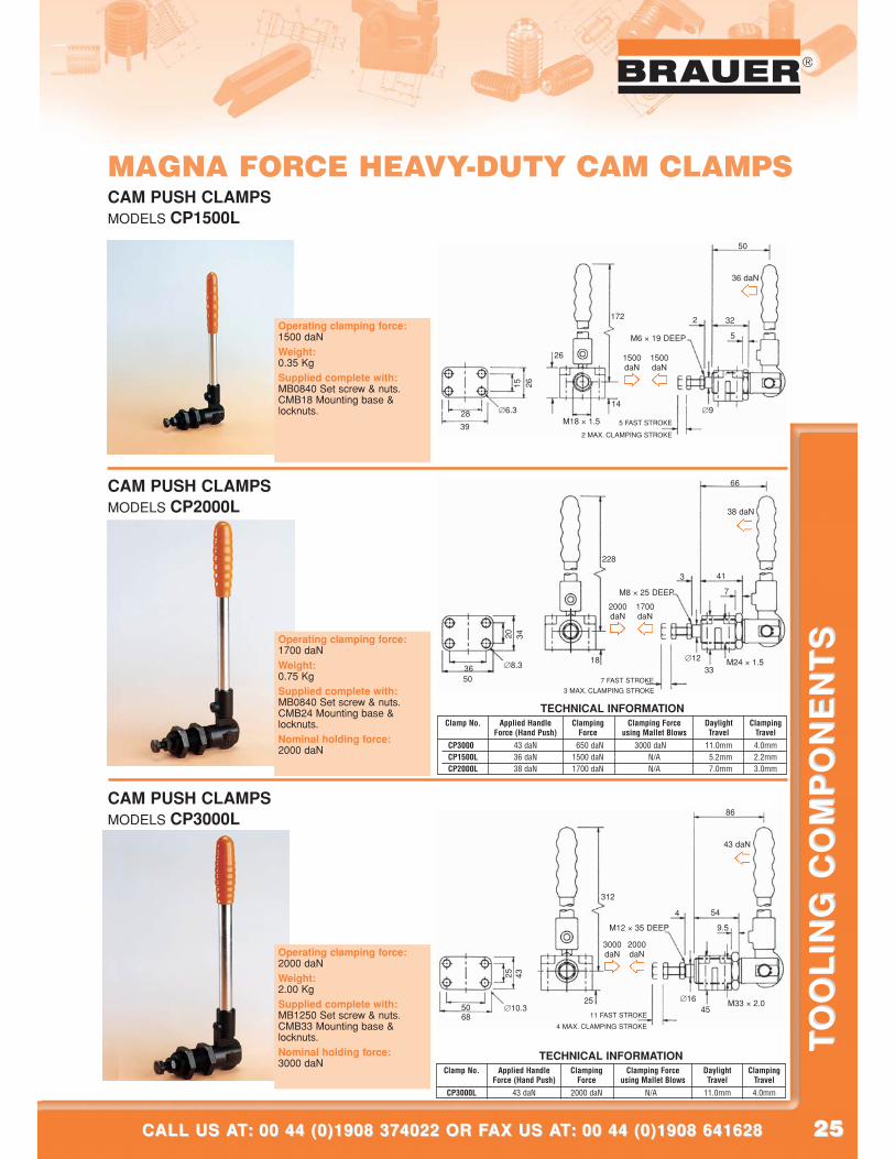
MAGNA FORCE HEAVY-DUTY CAM CLAMPS
Clamp No. Applied Handle Clamping Clamping Force Daylight ClampingForce (Hand Push) Force using Mallet Blows Travel Travel
CAM PUSH CLAMPSMODELS CP2000L
CP3000L 43 daN 650 daN 3000 daN 11.0mm 4.0mmCP1500L 36 daN 1500 daN N/A 5.2mm 2.2mmCP2000L 38 daN 1700 daN N/A 7.0mm 3.0mm
TECHNICAL INFORMATION
∅9
32
5
∅6.3
15
50
36 daN
M6 × 19 DEEP
M18 × 1.539
28
2
14
172
26
26
5 FAST STROKE
2 MAX. CLAMPING STROKE
1500daN
1500daN
CAM PUSH CLAMPSMODELS CP3000L
∅1645
M33 × 2.0
54
9.5
∅10.3
25
86
43 daN
M12 × 35 DEEP
6850
4
312
25
43
11 FAST STROKE
4 MAX. CLAMPING STROKE
3000daN
2000daN
Clamp No. Applied Handle Clamping Clamping Force Daylight ClampingForce (Hand Push) Force using Mallet Blows Travel Travel
CP3000L 43 daN 2000 daN N/A 11.0mm 4.0mm
TECHNICAL INFORMATION
CAM PUSH CLAMPSMODELS CP1500L
∅1233
M24 × 1.5
41
7
∅8.3
20
66
38 daN
M8 × 25 DEEP
5036
3
228
18
34
7 FAST STROKE
3 MAX. CLAMPING STROKE
2000daN
1700daN
Operating clamping force: 1500 daNWeight:0.35 KgSupplied complete with: MB0840 Set screw & nuts. CMB18 Mounting base &locknuts.
Operating clamping force: 1700 daNWeight:0.75 KgSupplied complete with: MB0840 Set screw & nuts. CMB24 Mounting base &locknuts.Nominal holding force: 2000 daN
Operating clamping force: 2000 daNWeight:2.00 KgSupplied complete with: MB1250 Set screw & nuts. CMB33 Mounting base &locknuts.Nominal holding force: 3000 daN
2626
®
LOOK INTO OUR WEBSITE AT: www.brauer.co.uk LOOK INTO OUR WEBSITE AT: www.brauer.co.uk
TO
OL
ING
CO
MP
ON
EN
TS
TO
OL
ING
CO
MP
ON
EN
TS
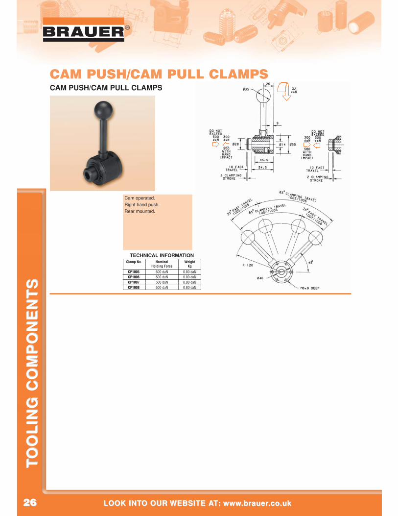
CAM PUSH/CAM PULL CLAMPSCAM PUSH/CAM PULL CLAMPS
Clamp No. Nominal WeightHolding Force Kg
CP1005A 500 daN 0.80 daNCP1006 500 daN 0.80 daNCP1007A 500 daN 0.80 daNCP1008A 500 daN 0.80 daN
TECHNICAL INFORMATION
Cam operated.Right hand push.Rear mounted.
2727
®
CALL US AT: 00 44 (0)1908 374022 OR FAX US AT: 00 44 (0)1908 641628CALL US AT: 00 44 (0)1908 374022 OR FAX US AT: 00 44 (0)1908 641628
TO
OL
ING
CO
MP
ON
EN
TS
TO
OL
ING
CO
MP
ON
EN
TS
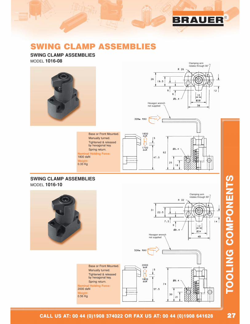
SWING CLAMP ASSEMBLIESSWING CLAMP ASSEMBLIESMODEL 1016-08
SWING CLAMP ASSEMBLIESMODEL 1016-10
Hexagon wrenchnot supplied
Clamping armrotates through 90°
Hexagon wrenchnot supplied
Clamping armrotates through 90°
Base or Front Mounted.Manually turned.Tightened & releasedby hexagonal key.Spring return.
Nominal Holding Force:1800 daNWeight: 0.33 Kg
Base or Front Mounted.Manually turned.Tightened & releasedby hexagonal key.Spring return.
Nominal Holding Force: 2000 daNWeight: 0.56 Kg
2828
®
LOOK INTO OUR WEBSITE AT: www.brauer.co.uk LOOK INTO OUR WEBSITE AT: www.brauer.co.uk
TO
OL
ING
CO
MP
ON
EN
TS
TO
OL
ING
CO
MP
ON
EN
TS
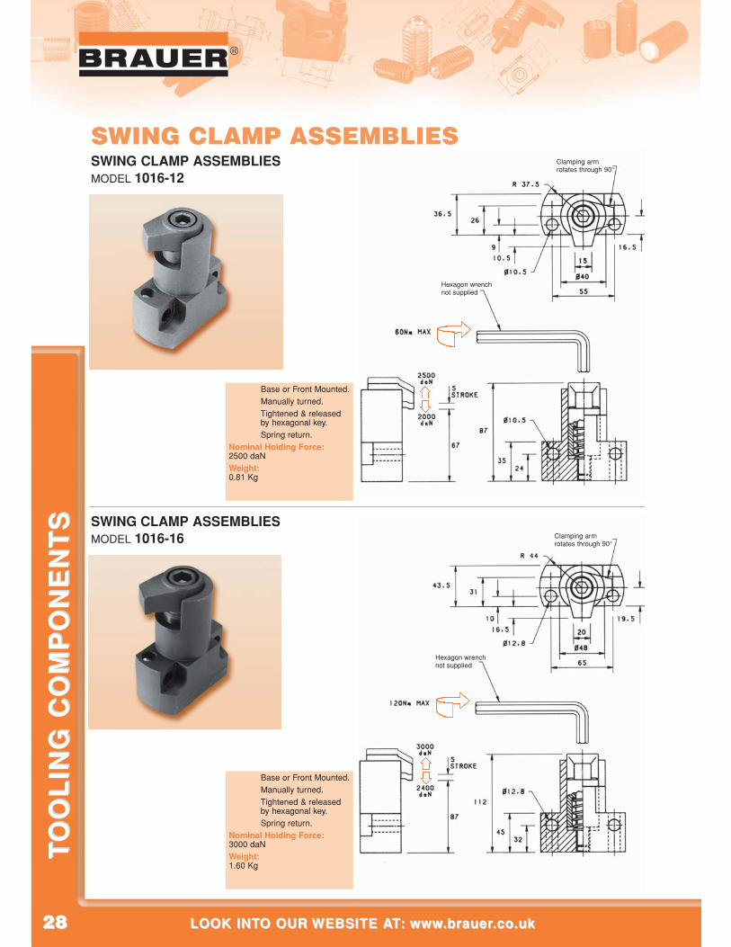
SWING CLAMP ASSEMBLIESSWING CLAMP ASSEMBLIESMODEL 1016-12
SWING CLAMP ASSEMBLIESMODEL 1016-16
Hexagon wrenchnot supplied
Clamping armrotates through 90°
Hexagon wrenchnot supplied
Clamping armrotates through 90°
Base or Front Mounted.Manually turned.Tightened & releasedby hexagonal key.Spring return.
Nominal Holding Force: 2500 daNWeight: 0.81 Kg
Base or Front Mounted.Manually turned.Tightened & releasedby hexagonal key.Spring return.
Nominal Holding Force: 3000 daNWeight: 1.60 Kg
2929
®
CALL US AT: 00 44 (0)1908 374022 OR FAX US AT: 00 44 (0)1908 641628CALL US AT: 00 44 (0)1908 374022 OR FAX US AT: 00 44 (0)1908 641628
TO
OL
ING
CO
MP
ON
EN
TS
TO
OL
ING
CO
MP
ON
EN
TS
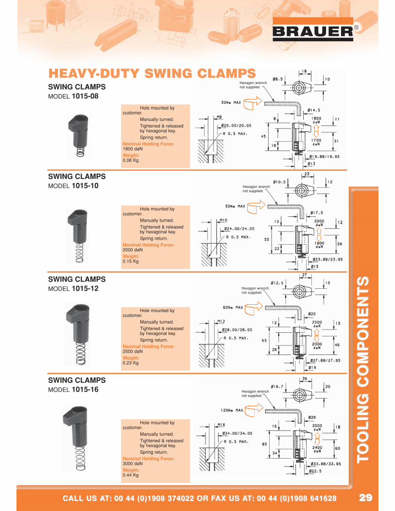
Hole mounted bycustomer.
Manually turned.Tightened & releasedby hexagonal key.Spring return.
Nominal Holding Force: 1800 daNWeight: 0.08 Kg
Hole mounted bycustomer.
Manually turned.Tightened & releasedby hexagonal key.Spring return.
Nominal Holding Force: 2000 daNWeight: 0.15 Kg
SWING CLAMPSMODEL 1015-08
SWING CLAMPSMODEL 1015-10
Hole mounted bycustomer.
Manually turned.Tightened & releasedby hexagonal key.Spring return.
Nominal Holding Force: 2500 daNWeight: 0.23 Kg
SWING CLAMPSMODEL 1015-12
Hole mounted bycustomer.
Manually turned.Tightened & releasedby hexagonal key.Spring return.
Nominal Holding Force: 3000 daNWeight: 0.44 Kg
SWING CLAMPSMODEL 1015-16
Hexagon wrenchnot supplied
Hexagon wrenchnot supplied
Hexagon wrenchnot supplied
Hexagon wrenchnot supplied
HEAVY-DUTY SWING CLAMPS
3030
®
LOOK INTO OUR WEBSITE AT: www.brauer.co.uk LOOK INTO OUR WEBSITE AT: www.brauer.co.uk
TO
OL
ING
CO
MP
ON
EN
TS
TO
OL
ING
CO
MP
ON
EN
TS
NEWNEW
PRODUCT
PRODUCT
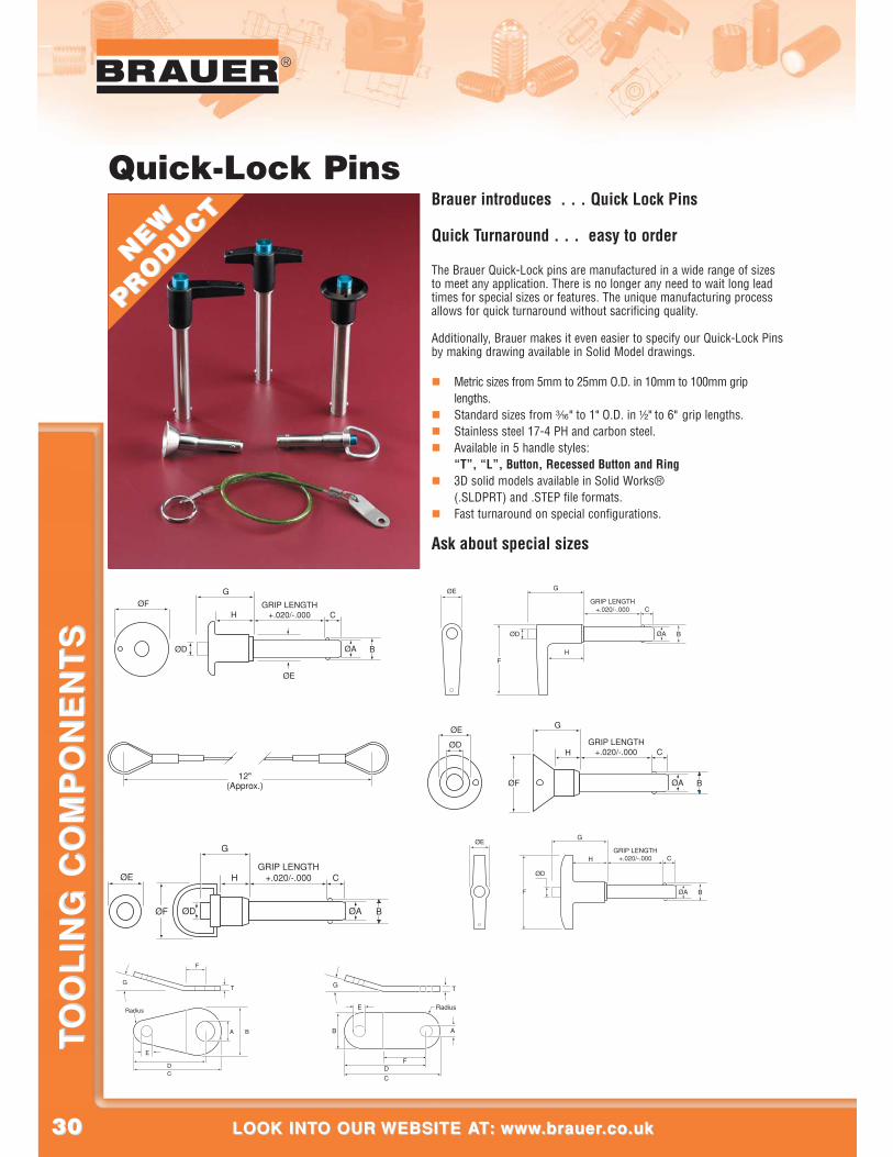
Quick-Lock PinsBrauer introduces . . . Quick Lock Pins
Quick Turnaround . . . easy to order
The Brauer Quick-Lock pins are manufactured in a wide range of sizesto meet any application. There is no longer any need to wait long leadtimes for special sizes or features. The unique manufacturing processallows for quick turnaround without sacrificing quality.
Additionally, Brauer makes it even easier to specify our Quick-Lock Pinsby making drawing available in Solid Model drawings.
� Metric sizes from 5mm to 25mm O.D. in 10mm to 100mm griplengths.
� Standard sizes from #/16” to 1” O.D. in !/2” to 6” grip lengths.� Stainless steel 17-4 PH and carbon steel.� Available in 5 handle styles:
“T”, “L”, Button, Recessed Button and Ring� 3D solid models available in Solid Works®
(.SLDPRT) and .STEP file formats.� Fast turnaround on special configurations.
Ask about special sizes
G
C
ØA B
H
ØD
ØF
ØE
GRIP LENGTH+.020/-.000
E
TG
Radius
F
DC
A B
D
G
C
B
F
T
E
A
Radius
G
C
ØA B
H
ØD
ØEGRIP LENGTH
+.020/-.000
ØF
G
C
ØA B
HØD
ØE
GRIP LENGTH+.020/-.000
ØF12"
(Approx.)
G
C
ØA B
H
ØD
ØE
GRIP LENGTH+.020/-.000
F
G
C
ØA B
H
ØD
ØEGRIP LENGTH
+.020/-.000
F
CALL US AT: 00 44 (0)1908 374022 OR FAX US AT: 00 44 (0)1908 641628CALL US AT: 00 44 (0)1908 374022 OR FAX US AT: 00 44 (0)1908 641628
TO
OL
ING
CO
MP
ON
EN
TS
TO
OL
ING
CO
MP
ON
EN
TS
MachineandJig
Components
3232
®
LOOK INTO OUR WEBSITE AT: www.brauer.co.uk LOOK INTO OUR WEBSITE AT: www.brauer.co.uk
TO
OL
ING
CO
MP
ON
EN
TS
TO
OL
ING
CO
MP
ON
EN
TS
distance
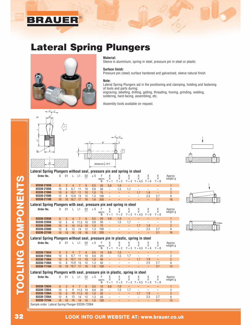
Lateral Spring PlungersMaterial:Sleeve in aluminium, spring in steel, pressure pin in steel or plastic
Surface finish:Pressure pin (steel) surface hardened and galvanised, sleeve natural finish
Note:Lateral Spring Plungers aid in the positioning and clamping, holding and fasteningof tools and parts during:engraving, labelling, drilling, galling, threading, honing, grinding, welding,soldering, hard-facing, assembling, etc.
Assembly tools available on request.
Order No.Lateral Spring Plungers with seal, pressure pin and spring in steel
03330-2203603330-2205603330-2206603330-2208603330-22106
D
610101216
D1
3568
10
L
46
101316
L1 -1
711,511,51418
D2+0,1
610101216
± S
0,50,81,01,31,6
Fapprox.
N205075
100200
Xif
Y = 10,8––––
Xif
Y = 21,01,5–––
Xif
Y = 3–
1,7–––
Xif
Y = 4,5––
1,7––
Xif
Y = 6––
1,92,5–
Xif
Y = 8–––
2,73,1
Approx.weight g
122816
Order No.Lateral Spring Plungers without seal, pressure pin in plastic, spring in steel
03330-7103403330-7105403330-7106403330-7108403330-71104
D
610101216
D1
3568
10
L
46,7
10,713,916,7
L1 -1
711111317
D2+0,1
610101216
± S
0,50,81,01,31,6
Fapprox.
N10204050
100
Xif
Y = 10,8––––
Xif
Y = 21,01,5–––
Xif
Y = 3–
1,7–––
Xif
Y = 4,5––
1,7––
Xif
Y = 6––
1,92,5–
Xif
Y = 8–––
2,73,1
Approx.weight g
122613
Order No.Lateral Spring Plungers with seal, pressure pin in plastic, spring in steel
03330-7203403330-7205403330-7206403330-7208403330-72104
D
610101216
D1
3568
10
L
46
101316
L1 -1
711,511,51418
D2+0,1
610101216
± S
0,50,81,01,31,6
Fapprox.
N10204050
100
Xif
Y = 10,8––––
Xif
Y = 21,01,5–––
Xif
Y = 3–
1,7–––
Xif
Y = 4,5––
1,7––
Xif
Y = 6––
1,92,5–
Xif
Y = 8–––
2,73,1
Approx.weight g
122613
Order No.Lateral Spring Plungers without seal, pressure pin and spring in steel
03330-2103603330-2105603330-2106603330-2108603330-21106
D
610101216
D1
3568
10
L
46,7
10,713,916,7
L1 -1
711111317
D2+0,1
610101216
± S
0,50,81,01,31,6
Fapprox.
N205075
100200
Xif
Y = 10,8––––
Xif
Y = 21,01,5–––
Xif
Y = 3–
1,7–––
Xif
Y = 4,5––
1,7––
Xif
Y = 6––
1,92,5–
Xif
Y = 8–––
2,73,1
Approx.weight g
122816
Sample order: Lateral Spring Plunger 03330-72064
3333
®
CALL US AT: 00 44 (0)1908 374022 OR FAX US AT: 00 44 (0)1908 641628CALL US AT: 00 44 (0)1908 374022 OR FAX US AT: 00 44 (0)1908 641628
TO
OL
ING
CO
MP
ON
EN
TS
TO
OL
ING
CO
MP
ON
EN
TS
®
assembly hole
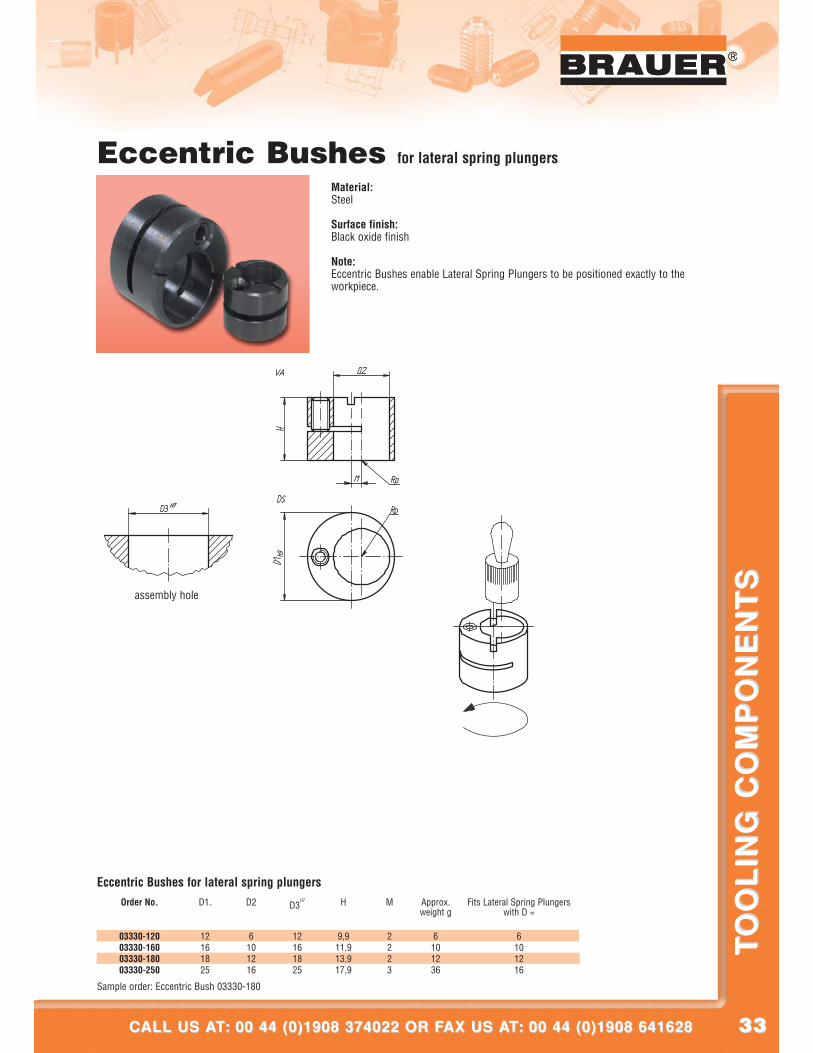
Eccentric Bushes for lateral spring plungers
Material:Steel
Surface finish:Black oxide finish
Note:Eccentric Bushes enable Lateral Spring Plungers to be positioned exactly to theworkpiece.
Sample order: Eccentric Bush 03330-180
Order No.
Eccentric Bushes for lateral spring plungers
03330-12003330-16003330-18003330-250
D1h9
12161825
D2
6101216
D3H7
12161825
H
9,911,913,917,9
M
2223
Approx.weight g
6101236
Fits Lateral Spring Plungerswith D =
6101216
3434
®
LOOK INTO OUR WEBSITE AT: www.brauer.co.uk LOOK INTO OUR WEBSITE AT: www.brauer.co.uk
TO
OL
ING
CO
MP
ON
EN
TS
TO
OL
ING
CO
MP
ON
EN
TS
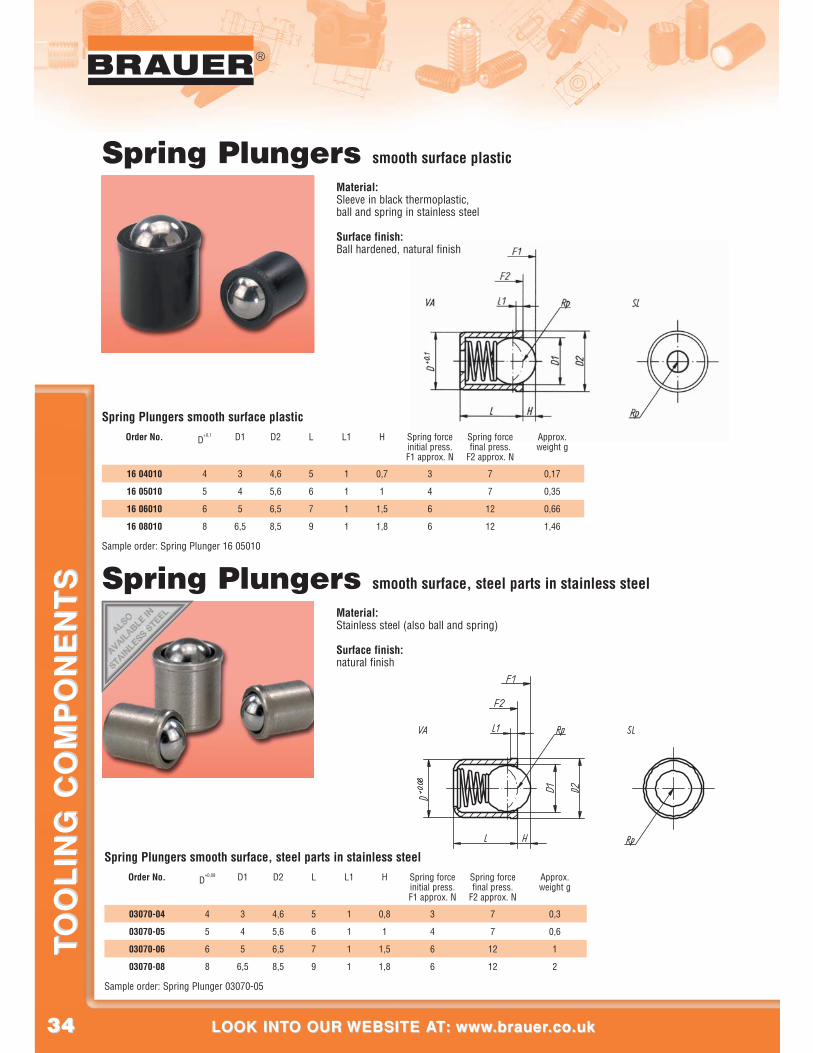
Spring Plungers smooth surface plastic
Material:Sleeve in black thermoplastic,ball and spring in stainless steel
Surface finish:Ball hardened, natural finish
Spring Plungers smooth surface, steel parts in stainless steel
Material:Stainless steel (also ball and spring)
Surface finish:natural finish
Sample order: Spring Plunger 16 05010
Order No.
Spring Plungers smooth surface plastic
16 04010
16 05010
16 06010
16 08010
D+0,1
4
5
6
8
D1
3
4
5
6,5
D2
4,6
5,6
6,5
8,5
L
5
6
7
9
L1
1
1
1
1
H
0,7
1
1,5
1,8
Spring forceinitial press.F1 approx. N
3
4
6
6
Spring forcefinal press.
F2 approx. N
7
7
12
12
Approx.weight g
0,17
0,35
0,66
1,46
Sample order: Spring Plunger 03070-05
Order No.
Spring Plungers smooth surface, steel parts in stainless steel
03070-04
03070-05
03070-06
03070-08
D+0,08
4
5
6
8
D1
3
4
5
6,5
D2
4,6
5,6
6,5
8,5
L
5
6
7
9
L1
1
1
1
1
H
0,8
1
1,5
1,8
Spring forceinitial press.F1 approx. N
3
4
6
6
Spring forcefinal press.
F2 approx. N
7
7
12
12
Approx.weight g
0,3
0,6
1
2
3535
®
CALL US AT: 00 44 (0)1908 374022 OR FAX US AT: 00 44 (0)1908 641628CALL US AT: 00 44 (0)1908 374022 OR FAX US AT: 00 44 (0)1908 641628
TO
OL
ING
CO
MP
ON
EN
TS
TO
OL
ING
CO
MP
ON
EN
TS
®
column locking
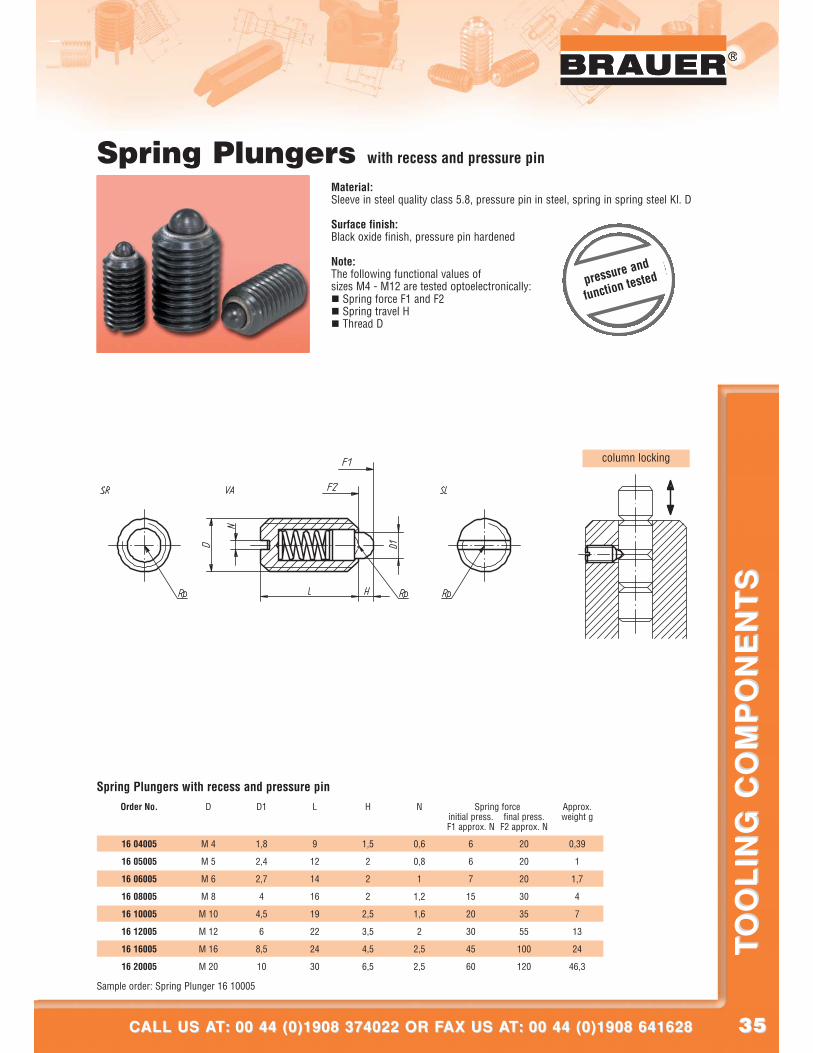
Spring Plungers with recess and pressure pin
Material:Sleeve in steel quality class 5.8, pressure pin in steel, spring in spring steel Kl. D
Surface finish:Black oxide finish, pressure pin hardened
Note:The following functional values ofsizes M4 - M12 are tested optoelectronically:� Spring force F1 and F2� Spring travel H� Thread D
16 04005
16 05005
16 06005
16 08005
16 10005
16 12005
16 16005
16 20005
Order No.
Spring Plungers with recess and pressure pinD
M 4
M 5
M 6
M 8
M 10
M 12
M 16
M 20
D1
1,8
2,4
2,7
4
4,5
6
8,5
10
L
9
12
14
16
19
22
24
30
H
1,5
2
2
2
2,5
3,5
4,5
6,5
N
0,6
0,8
1
1,2
1,6
2
2,5
2,5
Spring force
6
6
7
15
20
30
45
60
final press.F2 approx. N
initial press.F1 approx. N
20
20
20
30
35
55
100
120
Approx.weight g
0,39
1
1,7
4
7
13
24
46,3
Sample order: Spring Plunger 16 10005
pressure and
function tested
3636
®
LOOK INTO OUR WEBSITE AT: www.brauer.co.uk LOOK INTO OUR WEBSITE AT: www.brauer.co.uk
TO
OL
ING
CO
MP
ON
EN
TS
TO
OL
ING
CO
MP
ON
EN
TS
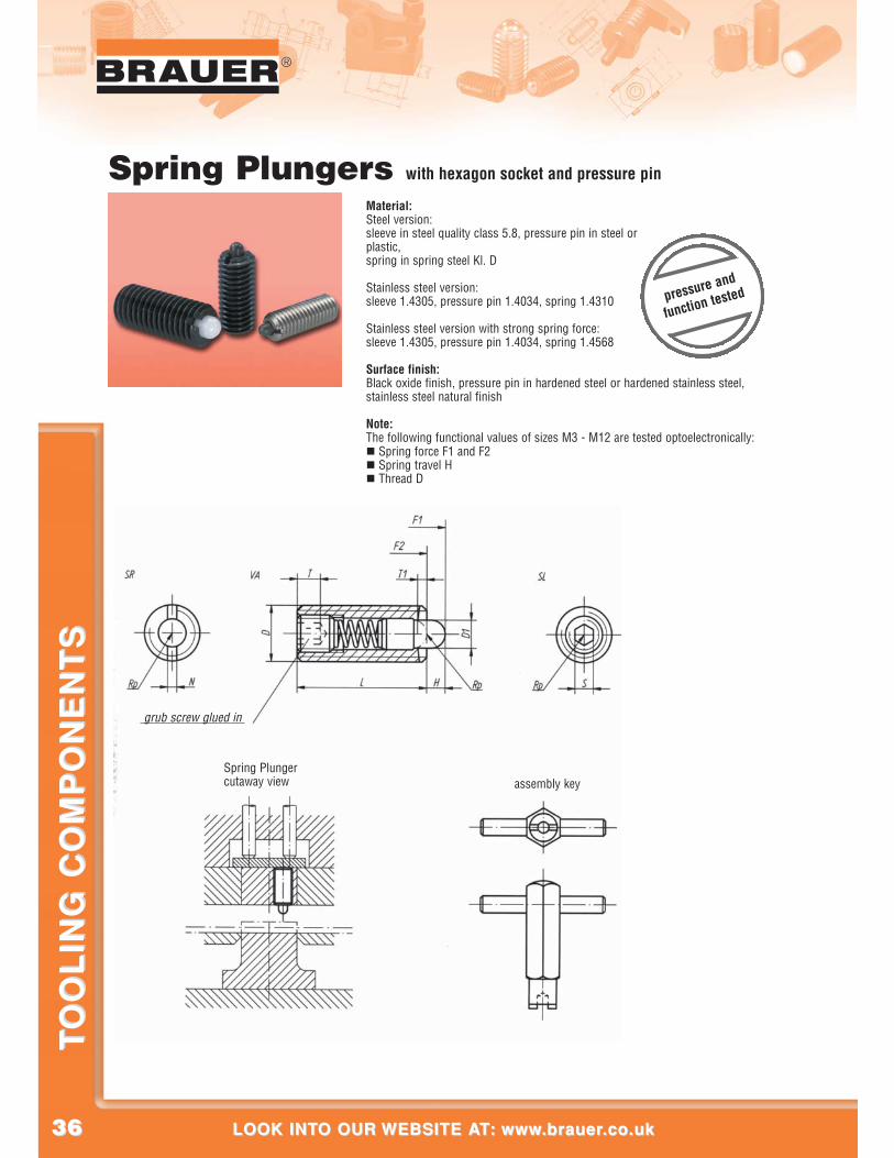
Spring Plungercutaway view assembly key
grub screw glued in
Spring Plungers with hexagon socket and pressure pin
Material:Steel version:sleeve in steel quality class 5.8, pressure pin in steel orplastic,spring in spring steel Kl. D
Stainless steel version:sleeve 1.4305, pressure pin 1.4034, spring 1.4310
Stainless steel version with strong spring force:sleeve 1.4305, pressure pin 1.4034, spring 1.4568
Surface finish:Black oxide finish, pressure pin in hardened steel or hardened stainless steel,stainless steel natural finish
Note:The following functional values of sizes M3 - M12 are tested optoelectronically:� Spring force F1 and F2� Spring travel H� Thread D
pressure and
function tested
3737
®
CALL US AT: 00 44 (0)1908 374022 OR FAX US AT: 00 44 (0)1908 641628CALL US AT: 00 44 (0)1908 374022 OR FAX US AT: 00 44 (0)1908 641628
TO
OL
ING
CO
MP
ON
EN
TS
TO
OL
ING
CO
MP
ON
EN
TS
®
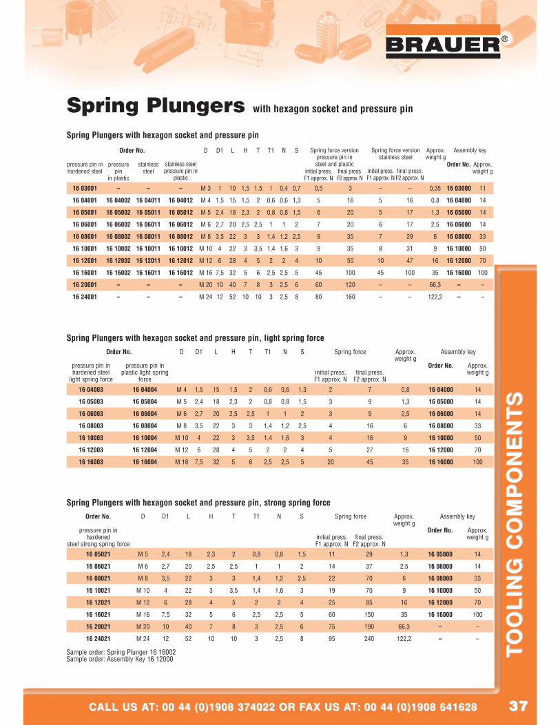
Spring Plungers with hexagon socket and pressure pin
16 03001
16 04001
16 05001
16 06001
16 08001
16 10001
16 12001
16 16001
16 20001
16 24001
pressure pin inhardened steel
Order No.
Spring Plungers with hexagon socket and pressure pin
pressurepin
in plastic
–
16 04002
16 0500 2
16 06002
16 08002
16 10002
16 12002
16 16002
–
–
stainlesssteel
–
16 04011
16 05011
16 06011
16 08011
16 10011
16 12011
16 16011
–
–
–
16 04012
16 05012
16 06012
16 08012
16 10012
16 12012
16 16012
–
–
stainless steelpressure pin in
plastic
D
M 3
M 4
M 5
M 6
M 8
M 10
M 12
M 16
M 20
M 24
D1
1
1,5
2,4
2,7
3,5
4
6
7,5
10
12
L
10
15
18
20
22
22
28
32
40
52
H
1,5
1,5
2,3
2,5
3
3
4
5
7
10
T
1,5
2
2
2,5
3
3,5
5
6
8
10
T1
1
0,6
0,8
1
1,4
1,4
2
2,5
3
3
N
0,4
0,6
0,8
1
1,2
1,6
2
2,5
2,5
2,5
S
0,7
1,3
1,5
2
2,5
3
4
5
6
8
initial press.F1 approx. N
0,5
5
6
7
9
9
10
45
60
80
final press.F2 approx. N
3
16
20
20
35
35
55
100
120
160
initial press.F1 approx. N
–
5
5
6
7
8
10
45
–
–
final press.F2 approx. N
–
16
17
17
29
31
47
100
–
–
Approx.weight g
0,35
0,8
1,3
2,5
6
9
16
35
66,3
122,2
Order No.
16 03000
16 04000
16 05000
16 06000
16 08000
16 10000
16 12000
16 16000
–
–
Approx.weight g
11
14
14
14
33
50
70
100
–
–
Spring force versionpressure pin insteel and plastic
Spring force versionstainless steel
Assembly key
16 04003
16 05003
16 06003
16 08003
16 10003
16 12003
16 16003
pressure pin inhardened steel
light spring force
Order No.
Spring Plungers with hexagon socket and pressure pin, light spring force
pressure pin inplastic light spring
force
16 04004
16 05004
16 06004
16 08004
16 10004
16 12004
16 16004
D
M 4
M 5
M 6
M 8
M 10
M 12
M 16
D1
1,5
2,4
2,7
3,5
4
6
7,5
L
15
18
20
22
22
28
32
H
1,5
2,3
2,5
3
3
4
5
T
2
2
2,5
3
3,5
5
6
T1
0,6
0,8
1
1,4
1,4
2
2,5
N
0,6
0,8
1
1,2
1,6
2
2,5
S
1,3
1,5
2
2,5
3
4
5
initial press.F1 approx. N
2
3
3
4
4
5
20
final press.F2 approx. N
7
9
9
16
16
27
45
Approx.weight g
0,8
1,3
2,5
6
9
16
35
Order No.
16 04000
16 05000
16 06000
16 08000
16 10000
16 12000
16 16000
Approx.weight g
14
14
14
33
50
70
100
Spring force Assembly key
16 05021
16 06021
16 08021
16 10021
16 12021
16 16021
16 20021
16 24021
pressure pin inhardened
steel strong spring force
Order No.
Spring Plungers with hexagon socket and pressure pin, strong spring forceD
M 5
M 6
M 8
M 10
M 12
M 16
M 20
M 24
D1
2,4
2,7
3,5
4
6
7,5
10
12
L
18
20
22
22
28
32
40
52
H
2,3
2,5
3
3
4
5
7
10
T
2
2,5
3
3,5
5
6
8
10
T1
0,8
1
1,4
1,4
2
2,5
3
3
N
0,8
1
1,2
1,6
2
2,5
2,5
2,5
S
1,5
2
2,5
3
4
5
6
8
initial press.F1 approx. N
11
14
22
19
25
60
75
95
final press.F2 approx. N
29
37
70
70
85
150
190
240
Approx.weight g
1,3
2,5
6
9
16
35
66,3
122,2
Order No.
16 05000
16 06000
16 08000
16 10000
16 12000
16 16000
–
–
Approx.weight g
14
14
33
50
70
100
–
–
Spring force Assembly key
Sample order: Spring Plunger 16 16002Sample order: Assembly Key 16 12000
3838
®
LOOK INTO OUR WEBSITE AT: www.brauer.co.uk LOOK INTO OUR WEBSITE AT: www.brauer.co.uk
TO
OL
ING
CO
MP
ON
EN
TS
TO
OL
ING
CO
MP
ON
EN
TS
K5120 0106
K5120 0108
K5120 0110
K5120 0112
K5120 0116
K5120 0120
K5120 0124
Order No.steel
Spring Plungers with hexagon socket and ballOrder No.
stainless steel
K5120 0506
K5120 0508
K5120 0510
K5120 0512
K5120 0516
K5120 0520
K5120 0524
D
M 6
M 8
M 10
M 12
M 16
M 20
M 24
D1
3,5
4,5
6
8
10
12
15
L
15
18
23
26
33
43
48
H
1
1,5
2
2,5
3,5
4,5
5,5
S
3
4
5
6
8
10
12
Spring force
9
15
20
30
65
80
90
final press.F2 approx. N
initial press.F1 approx. N
13
30
35
55
125
160
180
Approx.weight g
2
4
8
12
31
64
100
K5120 2106
K5120 2108
K5120 2110
K5120 2112
K5120 2116
K5120 2120
K5120 2124
Order No.steel
strong spring force
Spring Plungers with hexagon socket and ball, strong spring forceOrder No.
stainless steelstrong spring force
K5120 2506
K5120 2508
K5120 2510
K5120 25 12
K5120 2516
K5120 2520
K5120 2524
D
M 6
M 8
M 10
M 12
M 16
M 20
M 24
D1
3,5
4,5
6
8
10
12
15
L
15
18
23
26
33
43
48
H
1
1,5
2
2,5
3,5
4,5
5,5
S
3
4
5
6
8
10
12
Spring force
28
47
66
66
90
115
130
final press.F2 approx. N
initial press.F1 approx. N
40
73
100
120
180
240
270
Approx.weight g
2
4
8
12
31
64
100
Sample order: Spring Plunger K5120 2110
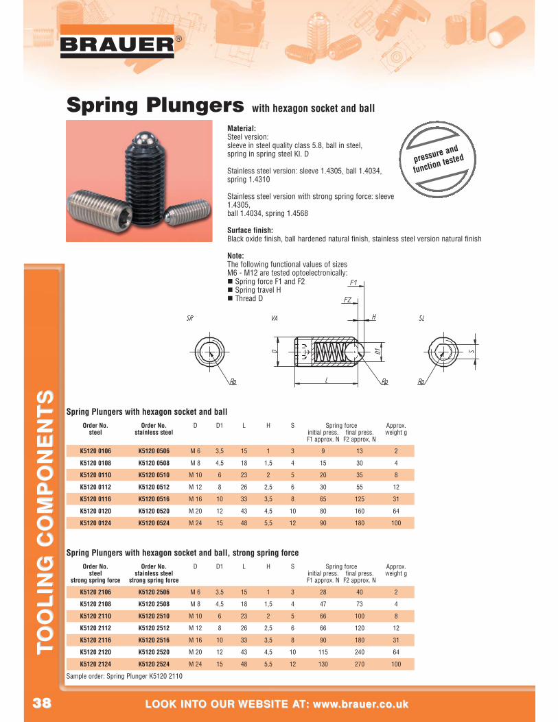
Spring Plungers with hexagon socket and ball
Material:Steel version:sleeve in steel quality class 5.8, ball in steel,spring in spring steel Kl. D
Stainless steel version: sleeve 1.4305, ball 1.4034,spring 1.4310
Stainless steel version with strong spring force: sleeve1.4305,ball 1.4034, spring 1.4568
Surface finish:Black oxide finish, ball hardened natural finish, stainless steel version natural finish
Note:The following functional values of sizesM6 - M12 are tested optoelectronically:� Spring force F1 and F2� Spring travel H� Thread D
pressure and
function tested
3939
®
CALL US AT: 00 44 (0)1908 374022 OR FAX US AT: 00 44 (0)1908 641628CALL US AT: 00 44 (0)1908 374022 OR FAX US AT: 00 44 (0)1908 641628
TO
OL
ING
CO
MP
ON
EN
TS
TO
OL
ING
CO
MP
ON
EN
TS
®
column locking
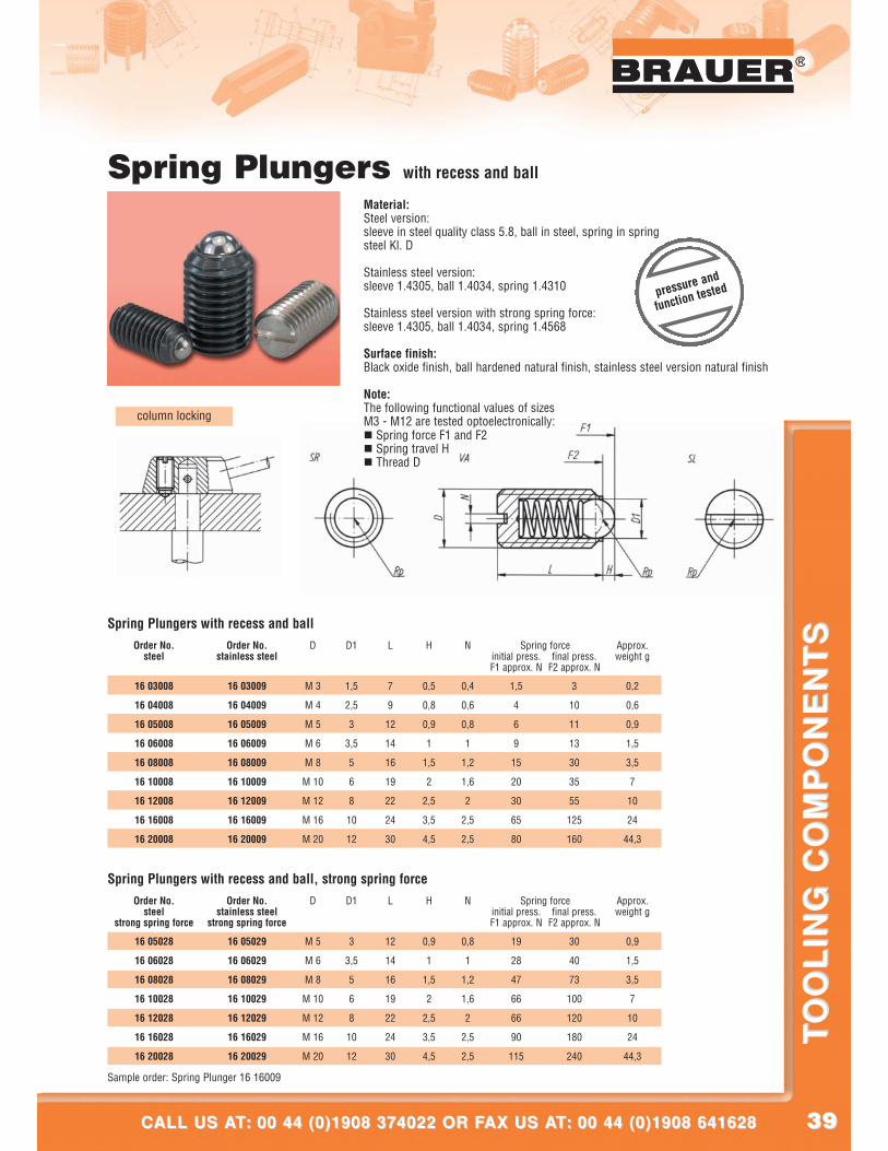
Spring Plungers with recess and ball
Material:Steel version:sleeve in steel quality class 5.8, ball in steel, spring in springsteel Kl. D
Stainless steel version:sleeve 1.4305, ball 1.4034, spring 1.4310
Stainless steel version with strong spring force:sleeve 1.4305, ball 1.4034, spring 1.4568
Surface finish:Black oxide finish, ball hardened natural finish, stainless steel version natural finish
Note:The following functional values of sizesM3 - M12 are tested optoelectronically:� Spring force F1 and F2� Spring travel H� Thread D
Order No.steel
Spring Plungers with recess and ball
16 03008
16 04008
16 05008
16 06008
16 08008
16 10008
16 12008
16 16008
16 20008
Order No.stainless steel
16 03009
16 04009
16 05009
16 06009
16 08009
16 10009
16 12009
16 16009
16 20009
D
M 3
M 4
M 5
M 6
M 8
M 10
M 12
M 16
M 20
D1
1,5
2,5
3
3,5
5
6
8
10
12
L
7
9
12
14
16
19
22
24
30
H
0,5
0,8
0,9
1
1,5
2
2,5
3,5
4,5
N
0,4
0,6
0,8
1
1,2
1,6
2
2,5
2,5
Spring force
1,5
4
6
9
15
20
30
65
80
final press.F2 approx. N
initial press.F1 approx. N
3
10
11
13
30
35
55
125
160
Approx.weight g
0,2
0,6
0,9
1,5
3,5
7
10
24
44,3
16 05028
16 06028
16 08028
16 10028
16 12028
16 16028
16 20028
Sample order: Spring Plunger 16 16009
Order No.steel
strong spring force
Spring Plungers with recess and ball, strong spring forceOrder No.
stainless steelstrong spring force
16 05029
16 06029
16 08029
16 10029
16 12029
16 16029
16 20029
D
M 5
M 6
M 8
M 10
M 12
M 16
M 20
D1
3
3,5
5
6
8
10
12
L
12
14
16
19
22
24
30
H
0,9
1
1,5
2
2,5
3,5
4,5
N
0,8
1
1,2
1,6
2
2,5
2,5
Spring force
19
28
47
66
66
90
115
final press.F2 approx. N
initial press.F1 approx. N
30
40
73
100
120
180
240
Approx.weight g
0,9
1,5
3,5
7
10
24
44,3
pressure and
function tested
4040
®
LOOK INTO OUR WEBSITE AT: www.brauer.co.uk LOOK INTO OUR WEBSITE AT: www.brauer.co.uk
TO
OL
ING
CO
MP
ON
EN
TS
TO
OL
ING
CO
MP
ON
EN
TS
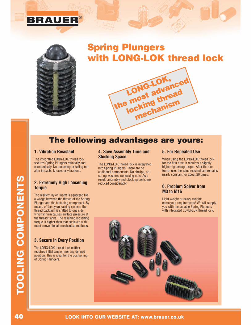
Spring Plungerswith LONG-LOK thread lock
1. Vibration ResistantThe integrated LONG-LOK thread locksecures Spring Plungers rationally andeconomically. No loosening or falling outafter impacts, knocks or vibrations.
2. Extremely High LooseningTorque The resilient nylon insert is squeezed likea wedge between the thread of the SpringPlunger and the fastening component. Bymeans of the nylon locking system, thethread backlash is shifted to one side,which in turn causes surface pressure atthe thread flanks. The resulting looseningtorque is higher than that achieved withmost conventional, mechanical methods.
3. Secure in Every PositionThe LONG-LOK thread lock neitherrequires initial tension nor any definedposition. This is ideal for the positioningof Spring Plungers.
4. Save Assembly Time andStocking SpaceThe LONG-LOK thread lock is integratedinto Spring Plungers. There are noadditional components. No circlips, nospring washers, no locking nuts. As aresult, assembly and stocking costs arereduced considerably.
5. For Repeated UseWhen using the LONG-LOK thread lockfor the first time, it requires a slightlyhigher tightening torque. After third orfourth use, the value reached last remainsnearly constant for about 20 times.
6. Problem Solver from M3 to M16Light-weight or heavy-weight: name your requirements! We will supplyyou with the suitable Spring Plungerswith integrated LONG-LOK thread lock.
The following advantages are yours:
LONG-LOK,
the most advanced
locking thread
mechanism
4141
®
CALL US AT: 00 44 (0)1908 374022 OR FAX US AT: 00 44 (0)1908 641628CALL US AT: 00 44 (0)1908 374022 OR FAX US AT: 00 44 (0)1908 641628
TO
OL
ING
CO
MP
ON
EN
TS
TO
OL
ING
CO
MP
ON
EN
TS
®
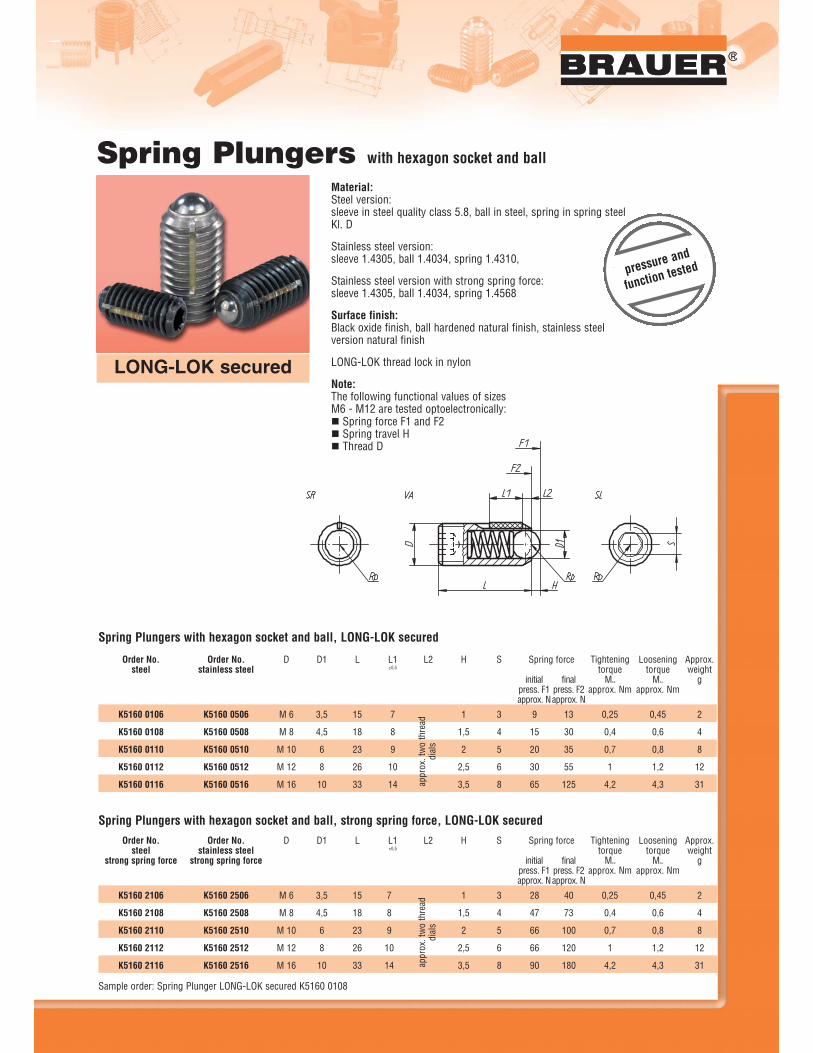
Material:Steel version:sleeve in steel quality class 5.8, ball in steel, spring in spring steelKl. D
Stainless steel version:sleeve 1.4305, ball 1.4034, spring 1.4310,
Stainless steel version with strong spring force:sleeve 1.4305, ball 1.4034, spring 1.4568
Surface finish:Black oxide finish, ball hardened natural finish, stainless steelversion natural finish
LONG-LOK thread lock in nylon
Note:The following functional values of sizesM6 - M12 are tested optoelectronically:� Spring force F1 and F2� Spring travel H� Thread D
Spring Plungers with hexagon socket and ball
LONG-LOK secured
1
1,5
2
2,5
3,5
K5160 0106
K5160 0108
K5160 0110
K5160 0112
K5160 0116
Order No.steel
Order No.stainless steel
Spring Plungers with hexagon socket and ball, LONG-LOK secured
K5160 0506
K5160 0508
K5160 0510
K5160 0512
K5160 0516
D
M 6
M 8
M 10
M 12
M 16
D1
3,5
4,5
6
8
10
L
15
18
23
26
33
L1±0,5
7
8
9
10
14
L2 H S
3
4
5
6
8
initialpress. F1approx. N
9
15
20
30
65
finalpress. F2approx. N
13
30
35
55
125
Approx.weight
g
2
4
8
12
31
Looseningtorque
MAus
approx. Nm
0,45
0,6
0,8
1,2
4,3
Tighteningtorque
MEIN
approx. Nm
0,25
0,4
0,7
1
4,2
Spring force
appr
ox. t
wo
thre
addi
als
1
1,5
2
2,5
3,5
Spring Plungers with hexagon socket and ball, strong spring force, LONG-LOK secured
Sample order: Spring Plunger LONG-LOK secured K5160 0108
Order No.steel
strong spring force
Order No.stainless steel
strong spring force
K5160 2106
K5160 2108
K5160 2110
K5160 2112
K5160 2116
K5160 2506
K5160 2508
K5160 2510
K5160 2512
K5160 2516
initialpress. F1approx. N
28
47
66
66
90
finalpress. F2approx. N
40
73
100
120
180
Approx.weight
g
2
4
8
12
31
Looseningtorque
MAus
approx. Nm
0,45
0,6
0,8
1,2
4,3
Tighteningtorque
MEIN
approx. Nm
0,25
0,4
0,7
1
4,2
Spring forceD
M 6
M 8
M 10
M 12
M 16
D1
3,5
4,5
6
8
10
L
15
18
23
26
33
L1±0,5
7
8
9
10
14
L2 H S
3
4
5
6
8appr
ox. t
wo
thre
addi
als
pressure and
function tested
4242
®
LOOK INTO OUR WEBSITE AT: www.brauer.co.uk LOOK INTO OUR WEBSITE AT: www.brauer.co.uk
TO
OL
ING
CO
MP
ON
EN
TS
TO
OL
ING
CO
MP
ON
EN
TS
LONG-LOK secured
assembly key grub screw glued in
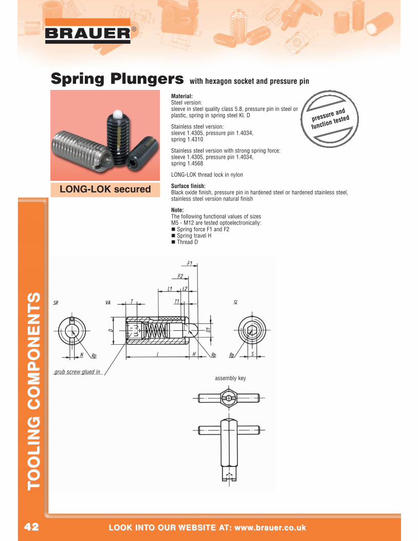
Spring Plungers with hexagon socket and pressure pin
Material:Steel version:sleeve in steel quality class 5.8, pressure pin in steel orplastic, spring in spring steel Kl. D
Stainless steel version:sleeve 1.4305, pressure pin 1.4034, spring 1.4310
Stainless steel version with strong spring force:sleeve 1.4305, pressure pin 1.4034,spring 1.4568
LONG-LOK thread lock in nylon
Surface finish:Black oxide finish, pressure pin in hardened steel or hardened stainless steel,stainless steel version natural finish
Note:The following functional values of sizesM5 - M12 are tested optoelectronically:� Spring force F1 and F2� Spring travel H� Thread D
pressure and
function tested
4343
®
CALL US AT: 00 44 (0)1908 374022 OR FAX US AT: 00 44 (0)1908 641628CALL US AT: 00 44 (0)1908 374022 OR FAX US AT: 00 44 (0)1908 641628
TO
OL
ING
CO
MP
ON
EN
TS
TO
OL
ING
CO
MP
ON
EN
TS
®
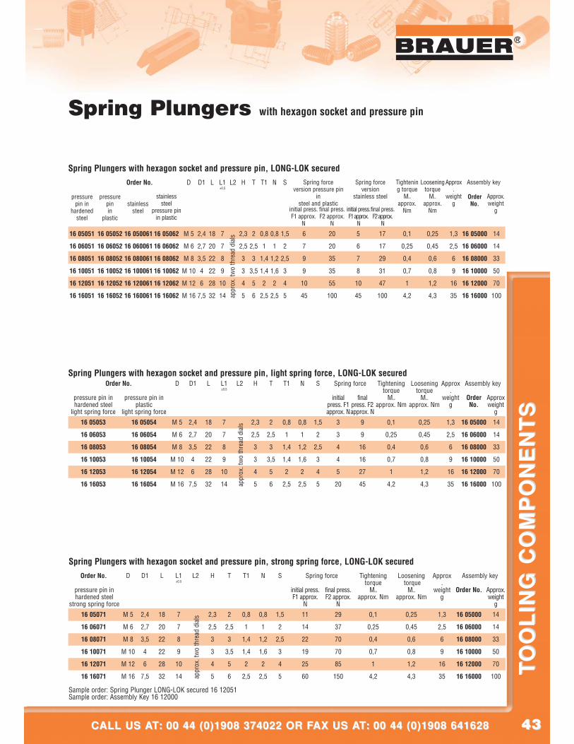
pressurepin in
hardenedsteel
Order No.
Spring Plungers with hexagon socket and pressure pin, LONG-LOK secured
16 05051
16 06051
16 08051
16 10051
16 12051
16 16051
pressurepin in
plastic
16 05052
16 06052
16 08052
16 10052
16 12052
16 16052
stainlesssteel
16 050061
16 060061
16 080061
16 100061
16 120061
16 160061
16 05062
16 06062
16 08062
16 10062
16 12062
16 16062
stainlesssteel
pressure pinin plastic
D
M 5
M 6
M 8
M 10
M 12
M 16
D1
2,4
2,7
3,5
4
6
7,5
L
18
20
22
22
28
32
L1±0,5
7
7
8
9
10
14
L2 H
2,3
2,5
3
3
4
5
T
2
2,5
3
3,5
5
6
T1
0,8
1
1,4
1,4
2
2,5
N
0,8
1
1,2
1,6
2
2,5
S
1,5
2
2,5
3
4
5
initial press.F1 approx.
N
6
7
9
9
10
45
final press.F2 approx.
N
20
20
35
35
55
100
initial press.F1 approx.
N
5
6
7
8
10
45
final press.F2 approx.
N
17
17
29
31
47
100
Approx.
weightg
1,3
2,5
6
9
16
35
Looseningtorque
MAus
approx.Nm
0,25
0,45
0,6
0,8
1,2
4,3
Tightening torque
MEIN
approx.Nm
0,1
0,25
0,4
0,7
1
4,2
OrderNo.
16 05000
16 06000
16 08000
16 10000
16 12000
16 16000
Approx.weight
g
14
14
33
50
70
100
Spring forceversion pressure pin
insteel and plastic
Spring forceversion
stainless steel
Assembly key
appr
ox. t
wo
thre
ad d
ials
Spring Plungers with hexagon socket and pressure pin
pressure pin in hardened steel
light spring force
Order No.Spring Plungers with hexagon socket and pressure pin, light spring force, LONG-LOK secured
16 05053
16 06053
16 08053
16 10053
16 12053
16 16053
pressure pin in plastic
light spring force
16 05054
16 06054
16 08054
16 10054
16 12054
16 16054
D
M 5
M 6
M 8
M 10
M 12
M 16
D1
2,4
2,7
3,5
4
6
7,5
L
18
20
22
22
28
32
L1±0,5
7
7
8
9
10
14
L2 H
2,3
2,5
3
3
4
5
T
2
2,5
3
3,5
5
6
T1
0,8
1
1,4
1,4
2
2,5
N
0,8
1
1,2
1,6
2
2,5
S
1,5
2
2,5
3
4
5
initialpress. F1approx. N
3
3
4
4
5
20
finalpress. F2approx. N
9
9
16
16
27
45
Approx.
weightg
1,3
2,5
6
9
16
35
Looseningtorque
MAus
approx. Nm
0,25
0,45
0,6
0,8
1,2
4,3
Tighteningtorque
MEIN
approx. Nm
0,1
0,25
0,4
0,7
1
4,2
OrderNo.
16 05000
16 06000
16 08000
16 10000
16 12000
16 16000
Approxweight
g
14
14
33
50
70
100
Spring force Assembly key
appr
ox. t
wo
thre
ad d
ials
pressure pin inhardened steel
strong spring force
Order No.
Spring Plungers with hexagon socket and pressure pin, strong spring force, LONG-LOK secured
16 05071
16 06071
16 08071
16 10071
16 12071
16 16071
D
M 5
M 6
M 8
M 10
M 12
M 16
D1
2,4
2,7
3,5
4
6
7,5
L
18
20
22
22
28
32
L1±0,5
7
7
8
9
10
14
L2 H
2,3
2,5
3
3
4
5
T
2
2,5
3
3,5
5
6
T1
0,8
1
1,4
1,4
2
2,5
N
0,8
1
1,2
1,6
2
2,5
S
1,5
2
2,5
3
4
5
initial press.F1 approx.
N
11
14
22
19
25
60
final press.F2 approx.
N
29
37
70
70
85
150
Approx.
weightg
1,3
2,5
6
9
16
35
Looseningtorque
MAus
approx. Nm
0,25
0,45
0,6
0,8
1,2
4,3
Tightening torque
MEIN
approx. Nm
0,1
0,25
0,4
0,7
1
4,2
Order No.
16 05000
16 06000
16 08000
16 10000
16 12000
16 16000
Approx.weight
g
14
14
33
50
70
100
Spring force Assembly key
Sample order: Spring Plunger LONG-LOK secured 16 12051Sample order: Assembly Key 16 12000
appr
ox. t
wo
thre
ad d
ials
4444
®
LOOK INTO OUR WEBSITE AT: www.brauer.co.uk LOOK INTO OUR WEBSITE AT: www.brauer.co.uk
TO
OL
ING
CO
MP
ON
EN
TS
TO
OL
ING
CO
MP
ON
EN
TS
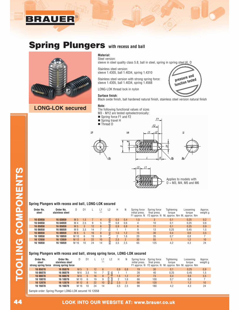
Applies to models withD = M3, M4, M5 and M6
pressure and
function tested
Material:Steel version:sleeve in steel quality class 5.8, ball in steel, spring in spring steel Kl. D
Stainless steel version:sleeve 1.4305, ball 1.4034, spring 1.4310
Stainless steel version with strong spring force:sleeve 1.4305, ball 1.4034, spring 1.4568
LONG-LOK thread lock in nylon
Surface finish:Black oxide finish, ball hardened natural finish, stainless steel version natural finish
Note:The following functional values of sizesM3 - M12 are tested optoelectronically:� Spring force F1 and F2� Spring travel H� Thread D
Spring Plungers with recess and ball
0,50,80,91
1,52
2,53,5
16 0305816 0405816 0505816 0605816 0805816 1005816 1205816 16058
Spring Plungers with recess and ball, LONG-LOK securedOrder No.
stainless steelOrder No.
steel
16 0305916 0405916 0505916 0605916 0805916 1005916 1205916 16059
D
M 3M 4M 5M 6M 8
M 10M 12M 16
D1
1,52,53
3,5568
10
L
79
121416192224
L1±0,5
456789
1014
L2
appr
ox. t
wo
thre
ad d
ials
H N
0,40,60,81
1,21,62
2,5
Spring forceinitial press.F1 approx. N
1,546915203065
Spring forcefinal press.
F2 approx. N3101113303555125
Tighteningtorque
MEIN approx. Nm0,10,10,10,250,40,71
4,2
Looseningtorque
MAus approx. Nm0,250,250,250,450,60,81,24,3
Approx.weight g
0,20,60,91,53,57
1024
16 0507816 0607816 0807816 1007816 1207816 16078
Order No.steel
strong spring force
Spring Plungers with recess and ball, strong spring force, LONG-LOK securedOrder No.
stainless steelstrong spring force
16 0507916 0607916 0807916 1007916 1207916 16079
D
M 5M 6M 8
M 10M 12M 16
D1
33,5568
10
L
121416192224
L1±0,5
67891014
L2
appr
ox. t
wo
thre
ad d
ials
H
0,91
1,52
2,53,5
N
0,81
1,21,62
2,5
Spring forceinitial press.F1 approx. N
192847666690
Spring forcefinal press.
F2 approx. N304073100120180
Tighteningtorque
MEIN approx. Nm0,10,250,40,71
4,2
Looseningtorque
MAus approx. Nm0,250,450,60,81,24,3
Approx.weight g
0,91,53,57
1024
Sample order: Spring Plunger LONG-LOK secured 16 12058
LONG-LOK secured
4545
®
CALL US AT: 00 44 (0)1908 374022 OR FAX US AT: 00 44 (0)1908 641628CALL US AT: 00 44 (0)1908 374022 OR FAX US AT: 00 44 (0)1908 641628
TO
OL
ING
CO
MP
ON
EN
TS
TO
OL
ING
CO
MP
ON
EN
TS
®
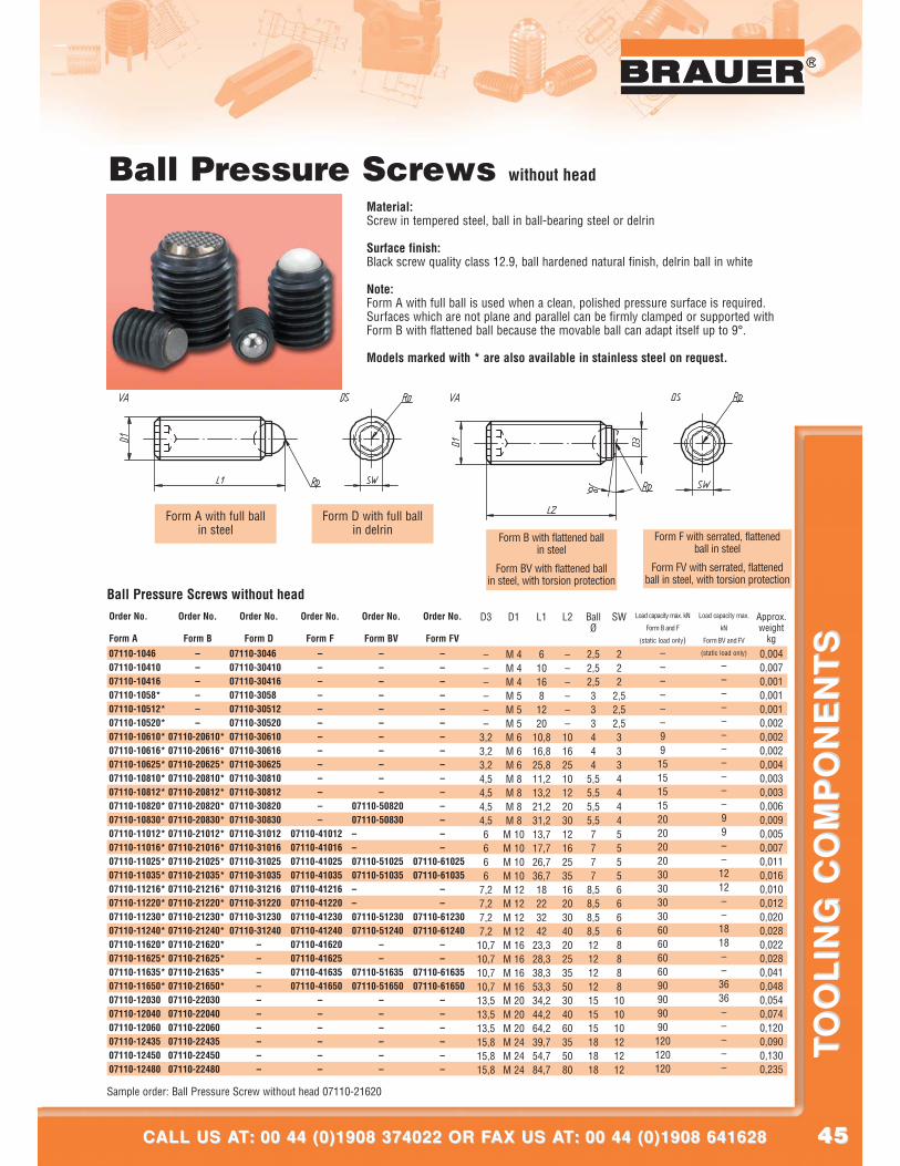
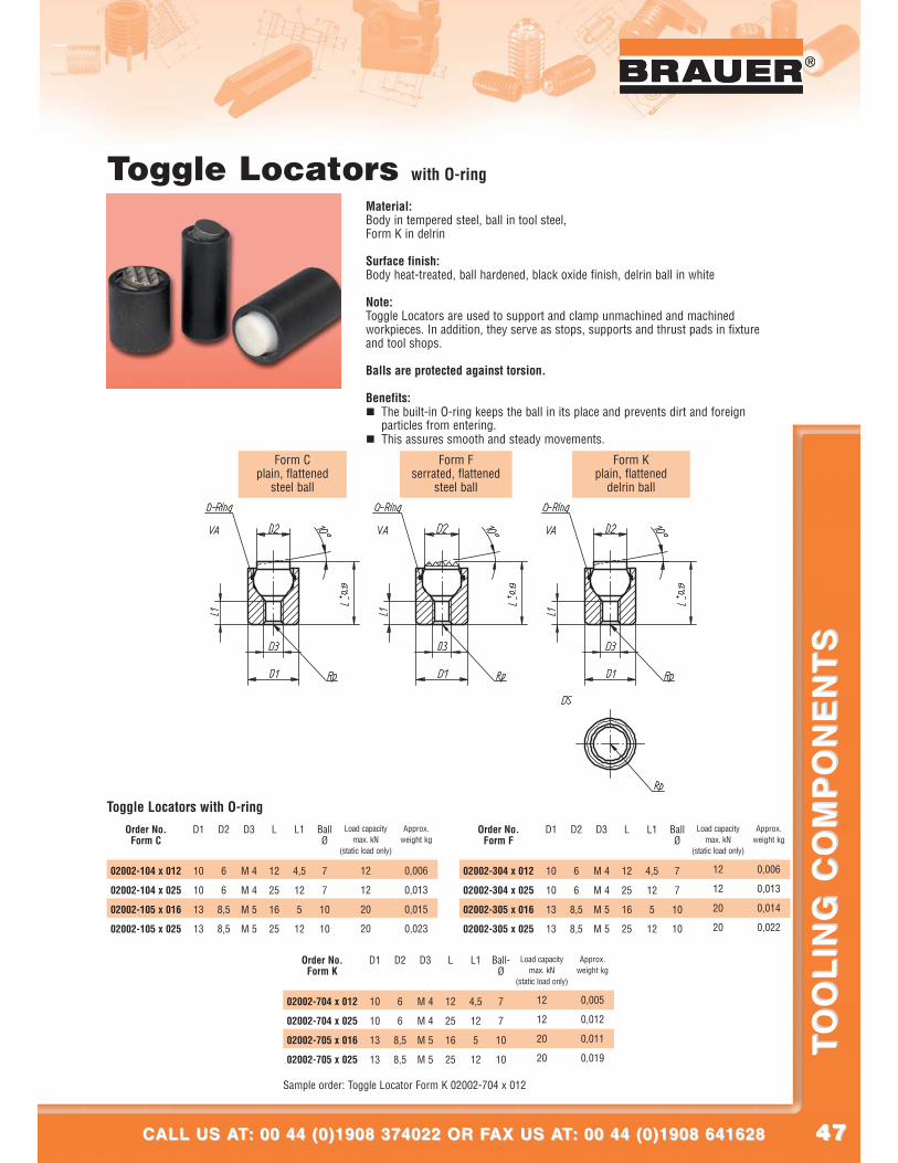
Form A with full ballin steel
Form D with full ballin delrin
Form B with flattened ballin steel
Form BV with flattened ballin steel, with torsion protection
Form F with serrated, flattenedball in steel
Form FV with serrated, flattenedball in steel, with torsion protection
Ball Pressure Screws without head
Material:Screw in tempered steel, ball in ball-bearing steel or delrin
Surface finish:Black screw quality class 12.9, ball hardened natural finish, delrin ball in white
Note:Form A with full ball is used when a clean, polished pressure surface is required.Surfaces which are not plane and parallel can be firmly clamped or supported withForm B with flattened ball because the movable ball can adapt itself up to 9°.
Models marked with * are also available in stainless steel on request.
Sample order: Ball Pressure Screw without head 07110-21620
D1
M 4M 4M 4M 5M 5M 5M 6M 6M 6M 8M 8M 8M 8M 10M 10M 10M 10M 12M 12M 12M 12M 16M 16M 16M 16M 20M 20M 20M 24M 24M 24
D3
––––––
3,23,23,24,54,54,54,56666
7,27,27,27,210,710,710,710,713,513,513,515,815,815,8
L1
6101681220
10,816,825,811,213,221,231,213,717,726,736,718223242
23,328,338,353,334,244,264,239,754,784,7
L2
––––––10162510122030121625351620304020253550304060355080
BallØ
2,52,52,5333444
5,55,55,55,57777
8,58,58,58,512121212151515181818
SW
222
2,52,52,53334444555566668888101010121212
Load capacity max.
kN
Form BV and FV
(static load only)
–––––––––––99––1212––1818––3636–––––
Load capacity max. kN
Form B and F
(static load only)
––––––991515151520202020303030306060606090909090120120120
Approx.weight
kg
0,0040,0070,0010,0010,0010,0020,0020,0020,0040,0030,0030,0060,0090,0050,0070,0110,0160,0100,0120,0200,0280,0220,0280,0410,0480,0540,0740,1200,0900,1300,235
Order No.
Form A
07110-104607110-1041007110-1041607110-1058*07110-10512*07110-10520*07110-10610*07110-10616*07110-10625*07110-10810*07110-10812*07110-10820*07110-10830*07110-11012*07110-11016*07110-11025*07110-11035*07110-11216*07110-11220*07110-11230*07110-11240*07110-11620*07110-11625*07110-11635*07110-11650*07110-1203007110-1204007110-1206007110-1243507110-1245007110-12480
Order No.
Form B
––––––
07110-20610*07110-20616*07110-20625*07110-20810*07110-20812*07110-20820*07110-20830*07110-21012*07110-21016*07110-21025*07110-21035*07110-21216*07110-21220*07110-21230*07110-21240*07110-21620*07110-21625*07110-21635*07110-21650*07110-2203007110-2204007110-2206007110-2243507110-2245007110-22480
Order No.
Form D
07110-304607110-3041007110-3041607110-305807110-3051207110-3052007110-3061007110-3061607110-3062507110-3081007110-3081207110-3082007110-3083007110-3101207110-3101607110-3102507110-3103507110-3121607110-3122007110-3123007110-31240
––––––––––
Order No.
Form F
–––––––––––––
07110-4101207110-4101607110-4102507110-4103507110-4121607110-4122007110-4123007110-4124007110-4162007110-4162507110-4163507110-41650
––––––
Order No.
Form BV
–––––––––––
07110-5082007110-50830––07110-5102507110-51035––07110-5123007110-51240
––
07110-5163507110-51650
––––––
Order No.
Form FV
–––––––––––––––
07110-6102507110-61035
––
07110-6123007110-61240
––
07110-6163507110-61650
––––––
Ball Pressure Screws without head
4646
®
LOOK INTO OUR WEBSITE AT: www.brauer.co.uk LOOK INTO OUR WEBSITE AT: www.brauer.co.uk
TO
OL
ING
CO
MP
ON
EN
TS
TO
OL
ING
CO
MP
ON
EN
TS
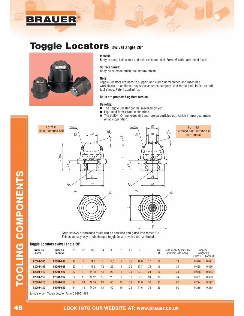
Toggle Locators swivel angle 20°
Sample order: Toggle Locator Form C 02001-108
D1
16
22
22
22
34
34
D2
7
11
11
11
18
18
D3
M 6
M 8
M 10
M 12
M 16
M 20
D4
5
7,5
7,5
7,5
13
13
L
17,5
26
26
26
40
40
L1
6
9
9
9
15
15
L2
0,4
0,8
0,8
0,8
0,6
0,6
E
19,6
27,7
27,7
27,7
41,6
41,6
S
17
24
24
24
36
36
BallØ
10
16
16
16
25
25
Load capacity max. kN(statical load only)
14
34
34
34
90
90
Form C
0,020
0,065
0,058
0,061
0,224
0,215
Form M
0,021
0,066
0,064
0,063
0,227
0,218
Approx.weight kg
Order No.Form C
02001-106
02001-108
02001-110
02001-112
02001-116
02001-120
Order No.Form M
02001-906
02001-908
02001-910
02001-912
02001-916
02001-920
Toggle Locators swivel angle 20°
Material:Body in steel, ball in rust and acid resistant steel, Form M with hard metal insert
Surface finish:Body black oxide finish, ball natural finish
Note:Toggle Locators are used to support and clamp unmachined and machinedworkpieces. In addition, they serve as stops, supports and thrust pads in fixture andtool shops. Patent applied for.
Balls are protected against torsion.
Benefits:� The Toggle Locator can be swivelled by 20°.� High load forces can be absorbed.� The built-in O-ring keeps dirt and foreign particles out, which in turn guarantees
reliable operation.
Grub screws or threaded studs can be screwed and glued into thread D3.This is an easy way of obtaining a toggle locator with external thread.
Form Mflattened ball, serration in
hard metal
Form Cplain, flattened ball
4747
®
CALL US AT: 00 44 (0)1908 374022 OR FAX US AT: 00 44 (0)1908 641628CALL US AT: 00 44 (0)1908 374022 OR FAX US AT: 00 44 (0)1908 641628
TO
OL
ING
CO
MP
ON
EN
TS
TO
OL
ING
CO
MP
ON
EN
TS
®
Toggle Locators with O-ring
Material:Body in tempered steel, ball in tool steel,Form K in delrin
Surface finish:Body heat-treated, ball hardened, black oxide finish, delrin ball in white
Note:Toggle Locators are used to support and clamp unmachined and machinedworkpieces. In addition, they serve as stops, supports and thrust pads in fixtureand tool shops.
Balls are protected against torsion.
Benefits:� The built-in O-ring keeps the ball in its place and prevents dirt and foreign
particles from entering.� This assures smooth and steady movements.
Toggle Locators with O-ring
Form Cplain, flattened
steel ball
Form Fserrated, flattened
steel ball
Form Kplain, flattened
delrin ball
D1
10
10
13
13
D2
6
6
8,5
8,5
D3
M 4
M 4
M 5
M 5
L
12
25
16
25
L1
4,5
12
5
12
BallØ
7
7
10
10
Load capacity max. kN
(static load only)
12
12
20
20
Approx.weight kg
0,006
0,013
0,015
0,023
Order No.Form C
02002-104 x 012
02002-104 x 025
02002-105 x 016
02002-105 x 025
D1
10
10
13
13
D2
6
6
8,5
8,5
D3
M 4
M 4
M 5
M 5
L
12
25
16
25
L1
4,5
12
5
12
BallØ
7
7
10
10
Load capacity max. kN
(static load only)
12
12
20
20
Approx.weight kg
0,006
0,013
0,014
0,022
Order No.Form F
02002-304 x 012
02002-304 x 025
02002-305 x 016
02002-305 x 025
D1
10
10
13
13
D2
6
6
8,5
8,5
D3
M 4
M 4
M 5
M 5
L
12
25
16
25
L1
4,5
12
5
12
Ball-Ø
7
7
10
10
Load capacity max. kN
(static load only)
12
12
20
20
Approx.weight kg
0,005
0,012
0,011
0,019
Order No.Form K
02002-704 x 012
02002-704 x 025
02002-705 x 016
02002-705 x 025
Sample order: Toggle Locator Form K 02002-704 x 012
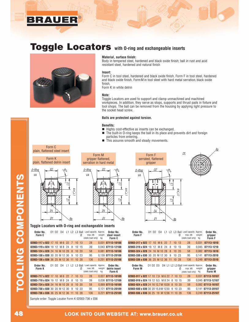
4848
®
LOOK INTO OUR WEBSITE AT: www.brauer.co.uk LOOK INTO OUR WEBSITE AT: www.brauer.co.uk
TO
OL
ING
CO
MP
ON
EN
TS
TO
OL
ING
CO
MP
ON
EN
TS
Form Cplain, flattened steel insert
Form Mgripper flattened,
serration in hard metalForm K
plain, flattened delrin insert
Form Fserrated, flattened
gripper
D1
1719243036
D2
1012162025
D3
7,99,512,715,919
D4
M 6M 8M 10M 12M 12
L1
2224283036
L2
788911
L3
1010101010
BallØ
1315202328
Approx.weight
kg
0,0310,0450,0820,1410,249
Order No.gripperForm M
07113-1010707113-1210707113-1610707113-2010707113-25107
Order No.Form M
02003-917 x 02202003-919 x 02402003-924 x 02802003-930 x 03002003-936 x 036
D1
1719243036
D2
1012162025
D4
M 6M 8M 10M 12M 12
L1
2224283036
L2
788911
L3
1010101010
Ball Ø
1315202328
Approx.weight
kg
0,0310,0450,0820,1410,249
Order No.gripperForm F
07113-101007113-121007113-161007113-201007113-2510
Order No.Form F
02003-317 x 02202003-319 x 02402003-324 x 02802003-330 x 03002003-336 x 036
Load capacitymax. kN
(static load only)
28395895136
Load capacitymax. kN
(static load only)
28395895136
Toggle Locators with O-ring and exchangeable inserts
Material, surface finish:Body in tempered steel, hardened and black oxide finish; ball in rust and acidresistant steel, hardened and natural finish
Insert:Form C in tool steel, hardened and black oxide finish, Form F in tool steel, hardenedand black oxide finish, Form M in tool steel with hard metal serration,black oxidefinish, Form K in white delrin
Note:Toggle Locators are used to support and clamp unmachined and machinedworkpieces. In addition, they serve as stops, supports and thrust pads in fixture andtool shops. The ball can be removed from the housing by applying light pressure tothe socket head screw.
Balls are protected against torsion.
Benefits:� Highly cost-effective as inserts can be exchanged.� The built-in O-ring keeps the ball in its place and prevents dirt and foreign
particles from entering.� This assures smooth and steady movements.
Order No.delrin insert
Form K
07113-1010907113-1210907113-1610907113-2010907113-25109
Toggle Locators with O-ring and exchangeable insertsD1
1719243036
D2
1012162025
D4
M 6M 8
M 10M 12M 12
L1
2224283036
L2
7889
11
L3
1010101010
Ball Ø
1315202328
Approx.weight
kg
0,0310,0430,0810,1390,251
Order No.steel insert
Form C
07113-1010807113-1210807113-1610807113-2010807113-25108
Order No.Form C
02003-117 x 02202003-119 x 02402003-124 x 02802003-130 x 03002003-136 x 036
Sample order: Toggle Locator Form K 02003-736 x 036
Load capacitymax. kN
(static load only)
28395895
136
D1
1719243036
D2
1012162025
D4
M 6M 8
M 10M 12M 12
L1
2224283036
L2
7889
11
L3
1010101010
BallØ
1315202328
Approx.weight
kg
0,0270,0360,0690,1210,221
Order No.Form K
02003-717 x 02202003-719 x 02402003-724 x 02802003-730 x 03002003-736 x 036
Load capacitymax. kN
(static load only)
28395895
136
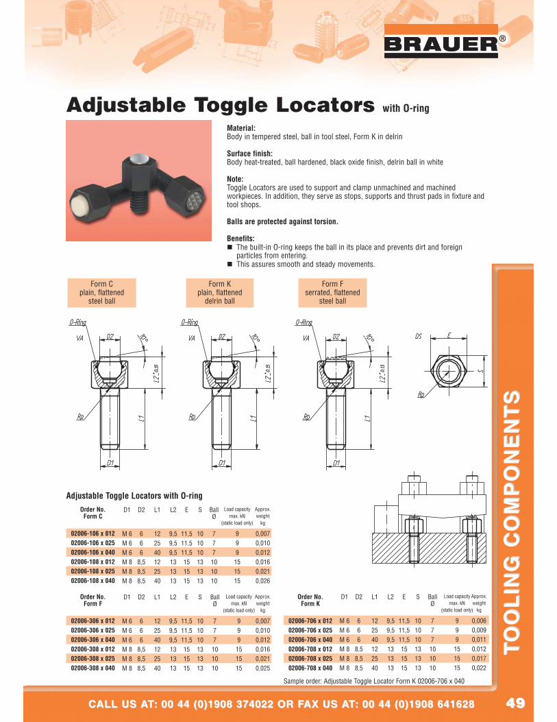
4949
®
CALL US AT: 00 44 (0)1908 374022 OR FAX US AT: 00 44 (0)1908 641628CALL US AT: 00 44 (0)1908 374022 OR FAX US AT: 00 44 (0)1908 641628
TO
OL
ING
CO
MP
ON
EN
TS
TO
OL
ING
CO
MP
ON
EN
TS
®
Adjustable Toggle Locators with O-ring
Material:Body in tempered steel, ball in tool steel, Form K in delrin
Surface finish:Body heat-treated, ball hardened, black oxide finish, delrin ball in white
Note:Toggle Locators are used to support and clamp unmachined and machinedworkpieces. In addition, they serve as stops, supports and thrust pads in fixture andtool shops.
Balls are protected against torsion.
Benefits:� The built-in O-ring keeps the ball in its place and prevents dirt and foreign
particles from entering.� This assures smooth and steady movements.
Form Cplain, flattened
steel ball
Form Fserrated, flattened
steel ball
Form Kplain, flattened
delrin ball
Adjustable Toggle Locators with O-ringD1
M 6M 6M 6M 8M 8M 8
D2
666
8,58,58,5
L1
122540122540
L2
9,59,59,5131313
E
11,511,511,5151515
S
101010131313
BallØ
777
101010
Order No.Form C
02006-106 x 01202006-106 x 02502006-106 x 04002006-108 x 01202006-108 x 02502006-108 x 040
D1
M 6M 6M 6M 8M 8M 8
D2
666
8,58,58,5
L1
122540122540
L2
9,59,59,5131313
E
11,511,511,5151515
S
101010131313
BallØ
777
101010
Order No.Form F
02006-306 x 01202006-306 x 02502006-306 x 04002006-308 x 01202006-308 x 02502006-308 x 040
Sample order: Adjustable Toggle Locator Form K 02006-706 x 040
D1
M 6M 6M 6M 8M 8M 8
D2
666
8,58,58,5
L1
122540122540
L2
9,59,59,5131313
E
11,511,511,5151515
S
101010131313
BallØ
777101010
Order No.Form K
02006-706 x 01202006-706 x 02502006-706 x 04002006-708 x 01202006-708 x 02502006-708 x 040
Load capacitymax. kN
(static load only)
999151515
Load capacitymax. kN
(static load only)
999151515
Load capacitymax. kN
(static load only)
999151515
Approx.weight
kg
0,0070,0100,0120,0160,0210,025
Approx.weight
kg
0,0060,0090,0110,0120,0170,022
Approx.weight
kg
0,0070,0100,0120,0160,0210,026
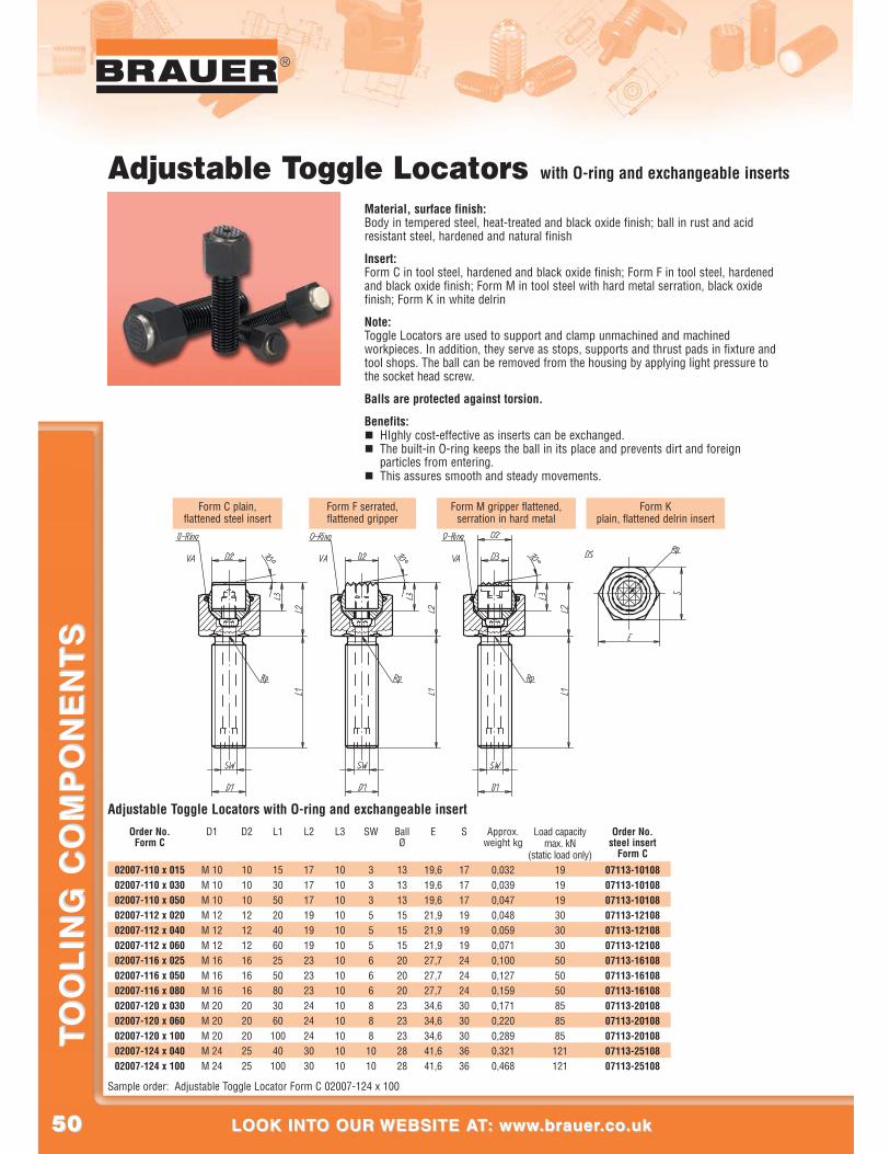
5050
®
LOOK INTO OUR WEBSITE AT: www.brauer.co.uk LOOK INTO OUR WEBSITE AT: www.brauer.co.uk
TO
OL
ING
CO
MP
ON
EN
TS
TO
OL
ING
CO
MP
ON
EN
TS
Form C plain,flattened steel insert
Form F serrated,flattened gripper
Form Kplain, flattened delrin insert
Form M gripper flattened,serration in hard metal
Adjustable Toggle Locators with O-ring and exchangeable inserts
Material, surface finish:Body in tempered steel, heat-treated and black oxide finish; ball in rust and acidresistant steel, hardened and natural finish
Insert:Form C in tool steel, hardened and black oxide finish; Form F in tool steel, hardenedand black oxide finish; Form M in tool steel with hard metal serration, black oxidefinish; Form K in white delrin
Note:Toggle Locators are used to support and clamp unmachined and machinedworkpieces. In addition, they serve as stops, supports and thrust pads in fixture andtool shops. The ball can be removed from the housing by applying light pressure tothe socket head screw.
Balls are protected against torsion.
Benefits:� HIghly cost-effective as inserts can be exchanged.� The built-in O-ring keeps the ball in its place and prevents dirt and foreign
particles from entering.� This assures smooth and steady movements.
Order No.Form C
02007-110 x 01502007-110 x 03002007-110 x 05002007-112 x 02002007-112 x 04002007-112 x 06002007-116 x 02502007-116 x 05002007-116 x 08002007-120 x 03002007-120 x 06002007-120 x 10002007-124 x 04002007-124 x 100
Adjustable Toggle Locators with O-ring and exchangeable insert
Sample order: Adjustable Toggle Locator Form C 02007-124 x 100
D1
M 10M 10M 10M 12M 12M 12M 16M 16M 16M 20M 20M 20M 24M 24
D2
1010101212121616162020202525
L1
1530502040602550803060
10040
100
L2
1717171919192323232424243030
L3
1010101010101010101010101010
SW
333555666888
1010
BallØ
1313131515152020202323232828
E
19,619,619,621,921,921,927,727,727,734,634,634,641,641,6
S
1717171919192424243030303636
Approx.weight kg
0,0320,0390,0470,0480,0590,0710,1000,1270,1590,1710,2200,2890,3210,468
Order No.steel insert
Form C
07113-1010807113-1010807113-1010807113-1210807113-1210807113-1210807113-1610807113-1610807113-1610807113-2010807113-2010807113-2010807113-2510807113-25108
Load capacitymax. kN
(static load only)191919303030505050858585121121
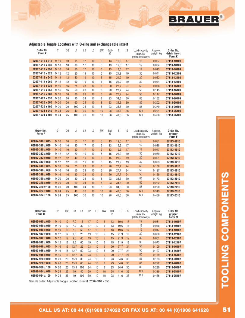
5151
®
CALL US AT: 00 44 (0)1908 374022 OR FAX US AT: 00 44 (0)1908 641628CALL US AT: 00 44 (0)1908 374022 OR FAX US AT: 00 44 (0)1908 641628
TO
OL
ING
CO
MP
ON
EN
TS
TO
OL
ING
CO
MP
ON
EN
TS
®
Adjustable Toggle Locators with O-ring and exchangeable insertD1
M 10M 10M 10M 12M 12M 12M 16M 16M 16M 20M 20M 20M 24M 24
D2
1010101212121616162020202525
L1
1530502040602550803060
10040
100
L2
1717171919192323232424243030
L3
1010101010101010101010101010
SW
333555666888
1010
Ball-Ø
1313131515152020202323232828
E
19,619,619,621,921,921,927,727,727,734,634,634,641,641,6
S
1717171919192424243030303636
Approx.weight kg
0,0270,0340,0430,0410,0520,0640,0880,1150,1470,1520,2020,2700,2910,438
Order No.delrin insert
Form K
07113-1010907113-1010907113-1010907113-1210907113-1210907113-1210907113-1610907113-1610907113-1610907113-2010907113-2010907113-2010907113-2510907113-25109
Order No.Form K
02007-710 x 01502007-710 x 03002007-710 x 05002007-712 x 02002007-712 x 04002007-712 x 06002007-716 x 02502007-716 x 05002007-716 x 08002007-720 x 03002007-720 x 06002007-720 x 10002007-724 x 04002007-724 x 100
D1
M 10M 10M 10M 12M 12M 12M 16M 16M 16M 20M 20M 20M 24M 24
D2
1010101212121616162020202525
L1
1530502040602550803060
10040
100
L2
1717171919192323232424243030
L3
1010101010101010101010101010
SW
333555666888
1010
BallØ
1313131515152020202323232828
E
19,619,619,621,921,921,927,727,727,734,634,634,641,641,6
S
1717171919192424243030303636
Approx.weight kg
0,0310,0380,0470,0500,0610,0730,1000,1270,1590,1730,2220,2900,3190,466
Order No.gripperForm F
07113-101007113-101007113-101007113-121007113-121007113-121007113-161007113-161007113-161007113-201007113-201007113-201007113-251007113-2510
Order No.Form F
02007-310 x 01502007-310 x 03002007-310 x 05002007-312 x 02002007-312 x 04002007-312 x 06002007-316 x 02502007-316 x 05002007-316 x 08002007-320 x 03002007-320 x 06002007-320 x 10002007-324 x 04002007-324 x 100
Sample order: Adjustable Toggle Locator Form M 02007-910 x 050
D1
M 10M 10M 10M 12M 12M 12M 16M 16M 16M 20M 20M 20M 24M 24
D2
1010101212121616162020202525
D3
7,97,97,99,59,59,5
12,712,712,715,915,915,91919
L1
1530502040602550803060
10040
100
L2
1717171919192323232424243030
L3
1010101010101010101010101010
SW
3335556668881010
BallØ
1313131515152020202323232828
E
19,619,619,621,921,921,927,727,727,734,634,634,641,641,6
S
1717171919192424243030303636
Approx.weight kg
0,0310,0380,0470,0500,0610,0730,1000,1270,1590,1730,2220,2900,3190,466
Order No.gripperForm M
07113-1010707113-1010707113-1010707113-1210707113-1210707113-1210707113-1610707113-1610707113-1610707113-2010707113-2010707113-2010707113-2510707113-25107
Order No.Form M
02007-910 x 01502007-910 x 03002007-910 x 05002007-912 x 02002007-912 x 04002007-912 x 06002007-916 x 02502007-916 x 05002007-916 x 08002007-920 x 03002007-920 x 06002007-920 x 10002007-924 x 04002007-924 x 100
Load capacitymax. kN
(static load only)191919303030505050858585121121
Load capacitymax. kN
(static load only)191919303030505050858585121121
Load capacitymax. kN
(static load only)191919303030505050858585121121
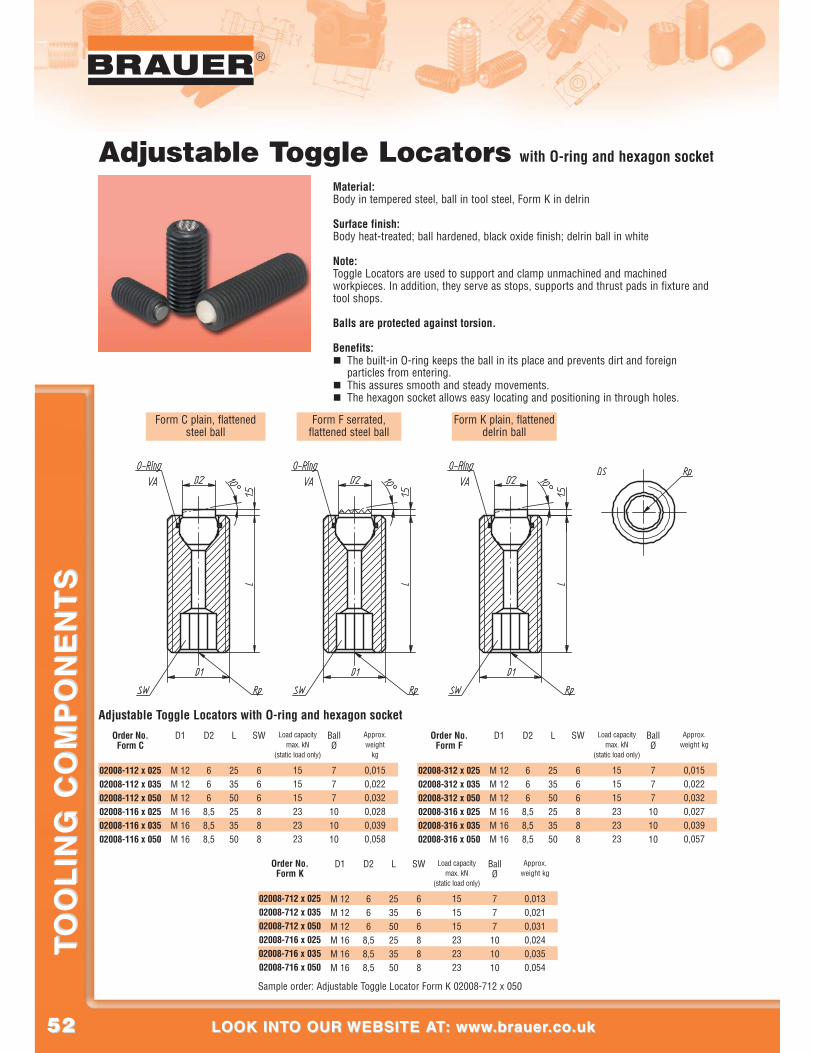
5252
®
LOOK INTO OUR WEBSITE AT: www.brauer.co.uk LOOK INTO OUR WEBSITE AT: www.brauer.co.uk
TO
OL
ING
CO
MP
ON
EN
TS
TO
OL
ING
CO
MP
ON
EN
TS
Adjustable Toggle Locators with O-ring and hexagon socketD1
M 12M 12M 12M 16M 16M 16
D2
666
8,58,58,5
L
253550253550
SW
666888
BallØ
777
101010
Approx.weight
kg
0,0150,0220,0320,0280,0390,058
Order No.Form C
02008-112 x 02502008-112 x 03502008-112 x 05002008-116 x 02502008-116 x 03502008-116 x 050
D1
M 12M 12M 12M 16M 16M 16
D2
666
8,58,58,5
L
253550253550
SW
666888
BallØ
777101010
Approx.weight kg
0,0150,0220,0320,0270,0390,057
Order No.Form F
02008-312 x 02502008-312 x 03502008-312 x 05002008-316 x 02502008-316 x 03502008-316 x 050
Sample order: Adjustable Toggle Locator Form K 02008-712 x 050
D1
M 12M 12M 12M 16M 16M 16
D2
666
8,58,58,5
L
253550253550
SW
666888
BallØ
777101010
Approx.weight kg
0,0130,0210,0310,0240,0350,054
Order No.Form K
02008-712 x 02502008-712 x 03502008-712 x 05002008-716 x 02502008-716 x 03502008-716 x 050
Load capacitymax. kN
(static load only)
151515232323
Load capacitymax. kN
(static load only)
151515232323
Load capacitymax. kN
(static load only)
151515232323
Form C plain, flattenedsteel ball
Form F serrated,flattened steel ball
Form K plain, flatteneddelrin ball
Adjustable Toggle Locators with O-ring and hexagon socket
Material:Body in tempered steel, ball in tool steel, Form K in delrin
Surface finish:Body heat-treated; ball hardened, black oxide finish; delrin ball in white
Note:Toggle Locators are used to support and clamp unmachined and machinedworkpieces. In addition, they serve as stops, supports and thrust pads in fixture andtool shops.
Balls are protected against torsion.
Benefits:� The built-in O-ring keeps the ball in its place and prevents dirt and foreign
particles from entering.� This assures smooth and steady movements.� The hexagon socket allows easy locating and positioning in through holes.
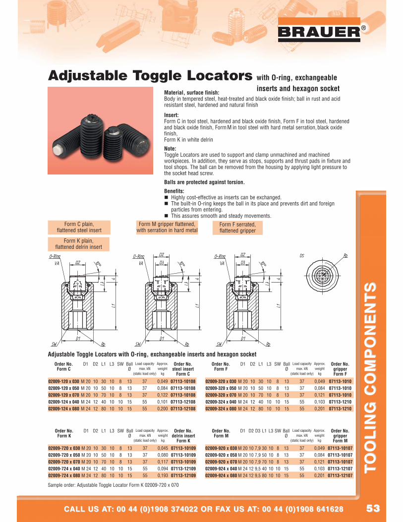
5353
®
CALL US AT: 00 44 (0)1908 374022 OR FAX US AT: 00 44 (0)1908 641628CALL US AT: 00 44 (0)1908 374022 OR FAX US AT: 00 44 (0)1908 641628
TO
OL
ING
CO
MP
ON
EN
TS
TO
OL
ING
CO
MP
ON
EN
TS
®
Adjustable Toggle Locators with O-ring, exchangeableinserts and hexagon socket
Material, surface finish:Body in tempered steel, heat-treated and black oxide finish; ball in rust and acidresistant steel, hardened and natural finish
Insert:Form C in tool steel, hardened and black oxide finish, Form F in tool steel, hardenedand black oxide finish, Form M in tool steel with hard metal serration,black oxidefinish,Form K in white delrin
Note:Toggle Locators are used to support and clamp unmachined and machinedworkpieces. In addition, they serve as stops, supports and thrust pads in fixture andtool shops. The ball can be removed from the housing by applying light pressure tothe socket head screw.
Balls are protected against torsion.
Benefits:� Highly cost-effective as inserts can be exchanged.� The built-in O-ring keeps the ball in its place and prevents dirt and foreign
particles from entering.� This assures smooth and steady movements.
Form C plain,flattened steel insert
Form F serrated,flattened gripper
Form M gripper flattened,with serration in hard metal
Form K plain,flattened delrin insert
Adjustable Toggle Locators with O-ring, exchangeable inserts and hexagon socketD1
M 20M 20M 20M 24M 24
D2
1010101212
L1
3050704080
L3
1010101010
SW
888
1010
BallØ
1313131515
Approx.weight
kg
0,0490,0840,1220,1010,200
Order No.steel insert
Form C
07113-1010807113-1010807113-1010807113-1210807113-12108
Order No.Form C
02009-120 x 03002009-120 x 05002009-120 x 07002009-124 x 04002009-124 x 080
Sample order: Adjustable Toggle Locator Form K 02009-720 x 070
D1
M 20M 20M 20M 24M 24
D2
1010101212
D3
7,97,97,99,59,5
L1
3050704080
L3
1010101010
SW
8881010
BallØ
1313131515
Approx.weight
kg
0,0490,0840,1210,1030,201
Order No.gripperForm M
07113-1010707113-1010707113-1010707113-1210707113-12107
Order No.Form M
02009-920 x 03002009-920 x 05002009-920 x 07002009-924 x 04002009-924 x 080
Load capacitymax. kN
(static load only)
3737375555
D1
M 20M 20M 20M 24M 24
D2
1010101212
L1
3050704080
L3
1010101010
SW
888
1010
BallØ
1313131515
Approx.weight
kg
0,0450,0800,1170,0940,193
Order No.delrin insert
Form K
07113-1010907113-1010907113-1010907113-1210907113-12109
Order No.Form K
02009-720 x 03002009-720 x 05002009-720 x 07002009-724 x 04002009-724 x 080
Load capacitymax. kN
(static load only)
3737375555
D1
M 20M 20M 20M 24M 24
D2
1010101212
L1
3050704080
L3
1010101010
SW
8881010
BallØ
1313131515
Approx.weight
kg
0,0490,0840,1210,1030,201
Order No.gripperForm F
07113-101007113-101007113-101007113-121007113-1210
Order No.Form F
02009-320 x 03002009-320 x 05002009-320 x 07002009-324 x 04002009-324 x 080
Load capacitymax. kN
(static load only)
3737375555
Load capacitymax. kN
(static load only)
3737375555
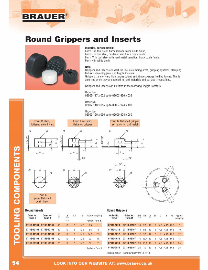
5454
®
LOOK INTO OUR WEBSITE AT: www.brauer.co.uk LOOK INTO OUR WEBSITE AT: www.brauer.co.uk
TO
OL
ING
CO
MP
ON
EN
TS
TO
OL
ING
CO
MP
ON
EN
TS
Form C plain,flattened steel insert
Form F serrated,flattened gripper
Form M flattened gripper,serration in hard metal
Form Kplain, flattened
delrin insert
Round InsertsD2-0,13
10
12
16
20
25
L3± 0,013
*(-0,13)
10
10
10
10
10
L4
5
5
5
5
5
G
M 5
M 5
M 6
M 6
M 6
Form K
1
1,5
2,5
4,5
7
Approx. weight g
Form C
5,5
8,5
14,5
23
37
Order No.Form C
07113-10108
07113-12108
07113-16108
07113-20108
07113-25108
Order No.Form K
07113-10109
07113-12109
07113-16109
07113-20109
07113-25109
Round Grippers
Sample order: Round Gripper 07113-2510
D2-0,13
10
12
12
16
20
25
D3
7,9
9,5
9,5
12,7
15,9
19
L3-0,13
10
10
12
10
10
10
L5
6
6
7
6
6
6
C
4,5
4,5
6
4,5
4,5
4,5
E
4,75
4,75
4,75
4,75
4,75
4,75
G
M 5
M 5
M 5
M 6
M 6
M 6
Approx.weight g
5
10
12
15
25
35
Order No.Form F
07113-1010
07113-1210
07113-1212
07113-1610
07113-2010
07113-2510
Order No.Form M
07113-10107
07113-12107
07113-12127
07113-16107
07113-20107
07113-25107* Applies to Form K
Round Grippers and InsertsMaterial, surface finish:Form C in tool steel, hardened and black oxide finish,Form F in tool steel, hardened and black oxide finish, Form M in tool steel with hard metal serration, black oxide finish,Form K in white delrin
Note:Grippers and Inserts are ideal for use in clamping arms, gripping systems, clampingfixtures, clamping jaws and toggle locators.Grippers transfer very high torque values and above average holding forces. This isalso true when they are applied to hard materials and surface irregularities.
Grippers and Inserts can be fitted in the following Toggle Locators:
Order No. 02003-117 x 022 up to 02003-936 x 036
Order No.02007-110 x 015 up to 02007-924 x 100
Order No.02009-120 x 030 up to 02009-924 x 080
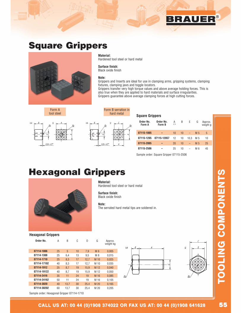
5555
®
CALL US AT: 00 44 (0)1908 374022 OR FAX US AT: 00 44 (0)1908 641628CALL US AT: 00 44 (0)1908 374022 OR FAX US AT: 00 44 (0)1908 641628
TO
OL
ING
CO
MP
ON
EN
TS
TO
OL
ING
CO
MP
ON
EN
TS
®
A
25252540254035504060
B
56,48,38,38,78,71111
13,713,7
C
10131717191924243030
D
7,99,5
12,712,715,915,91919
25,425,4
G
M 6M 8
M 10M 10M 12M 12M 16M 16M 20M 20
Approx.weight kg
0,0050,0150,0250,0350,0400,0500,0850,1050,1650,205
Order No.
07114-100607114-130807114-171007114-1710207114-191207114-1912207114-241607114-2416207114-302007114-30202
Sample order: Hexagonal Gripper 07114-1710
Hexagonal Grippers
Form Atool steel
Form B serration inhard metal
Square Grippers
Sample order: Square Gripper 07115-2506
A-0,15
10
12
20
25
B
10
10
10
10
E
–
10,3
–
–
G
M 5
M 5
M 5
M 6
Approx.weight g
5
10
25
45
Order No.Form A
07115-1005
07115-1205
07115-2005
07115-2506
Order No.Form B
–
07115-12057
–
–
Square GrippersMaterial:Hardened tool steel or hard metal
Surface finish:Black oxide finish
Note:Grippers and Inserts are ideal for use in clamping arms, gripping systems, clampingfixtures, clamping jaws and toggle locators.Grippers transfer very high torque values and above average holding forces. This isalso true when they are applied to hard materials and surface irregularities.Grippers guarantee above average clamping forces at high cutting forces.
Hexagonal GrippersMaterial:Hardened tool steel or hard metal
Surface finish:Black oxide finish
Note:The serrated hard metal tips are soldered in.
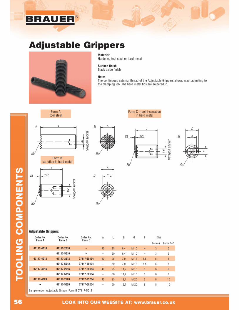
5656
®
LOOK INTO OUR WEBSITE AT: www.brauer.co.uk LOOK INTO OUR WEBSITE AT: www.brauer.co.uk
TO
OL
ING
CO
MP
ON
EN
TS
TO
OL
ING
CO
MP
ON
EN
TS
Adjustable Grippers
Sample order: Adjustable Gripper Form B 07117-5012
A
40
–
40
–
40
–
40
–
L
25
50
25
50
25
50
25
50
B
6,4
6,4
7,9
7,9
11,2
11,2
12,7
12,7
G
M 10
M 10
M 12
M 12
M 16
M 16
M 20
M 20
F
–
–
6,5
6,5
8
8
8
8
SW
Form A
3
3
5
5
6
6
8
8
Order No.Form A
07117-4010
_
07117-4012
–
07117-4016
–
07117-4020
–
Order No.Form B
07117-2510
07117-5010
07117-2512
07117-5012
07117-2516
07117-5016
07117-2520
07117-5020
Order No.Form C
–
–
07117-25124
07117-50124
07117-25164
07117-50164
07117-25204
07117-50204
Form C 4-point-serrationin hard metal
hexa
gon
sock
et
Form Atool steel
Form Bserration in hard metal
hexa
gon
sock
et
hexa
gon
sock
et
Adjustable GrippersMaterial:Hardened tool steel or hard metal
Surface finish:Black oxide finish
Note:The continuous external thread of the Adjustable Grippers allows exact adjusting tothe clamping job. The hard metal tips are soldered in.
Form B+C
5
5
6
6
8
8
10
10
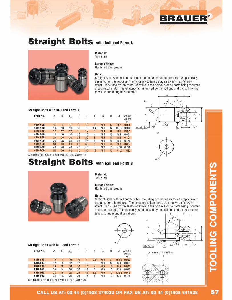
5757
®
CALL US AT: 00 44 (0)1908 374022 OR FAX US AT: 00 44 (0)1908 641628CALL US AT: 00 44 (0)1908 374022 OR FAX US AT: 00 44 (0)1908 641628
TO
OL
ING
CO
MP
ON
EN
TS
TO
OL
ING
CO
MP
ON
EN
TS
®
Straight Bolts with ball end Form B
Material:Tool steel
Surface finish:Hardened and ground
Note:Straight Bolts with ball end facilitate mounting operations as they are specificallydesigned for this process. The tendency to jam parts, also known as “drawereffect”, is caused by forces not effective in the bolt axis or by parts being mountedat a slanted angle. This tendency is minimised by the ball end and the ball incline(see also mounting illustration).
mounting illustration
Straight Bolts with ball end Form A
Material:Tool steel
Surface finish:Hardened and ground
Note:Straight Bolts with ball end facilitate mounting operations as they are specificallydesigned for this process. The tendency to jam parts, also known as “drawereffect”, is caused by forces not effective in the bolt axis or by parts being mountedat a slanted angle. This tendency is minimised by the ball end and the ball incline(see also mounting illustration).
An6
81012162025304050
Bg6
81012162025304050
C-0,01
-0,05
81012162025304050
D
101315202525304050
E
81012162025304050
F
22,534568
1012
G
M 3M 3M 4M 5M 5M 5M 6M 6M 6
H
668101010121212
J
R 2R 2,5R 3R 4R 5R 6R 8R 10R 12
Approx.weight
kg0,0060,012 0,0210,0510,1010,1760,3070,7291,422
Sample order: Straight Bolt with ball end 03107-12
Straight Bolts with ball end Form AOrder No.
03107-0803107-1003107-1203107-1603107-2003107-2503107-3003107-4003107-50
Ag6
101216202225
Bn6
78
12141618
C-0,01
-0,05
101216202225
D
101216202225
E
78
12141618
F
2,5345
5,56
G
M 3M 4M 5M 5M 5M 5
H
6810101010
J
R 2,5R 3R 4R 5
R 5,5R 6
Approx.weight
kg0,0070,0110,0300,0570,0790,116
Order No.
03108-1003108-1203108-1603108-2003108-2203108-25
Sample order: Straight Bolt with ball end 03108-20
Straight Bolts with ball end Form B
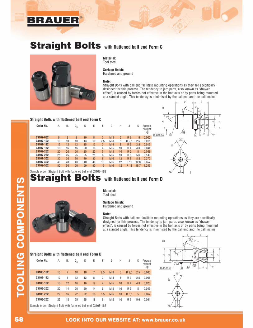
5858
®
LOOK INTO OUR WEBSITE AT: www.brauer.co.uk LOOK INTO OUR WEBSITE AT: www.brauer.co.uk
TO
OL
ING
CO
MP
ON
EN
TS
TO
OL
ING
CO
MP
ON
EN
TS Straight Bolts with flattened ball end Form D
Material:Tool steel
Surface finish:Hardened and ground
Note:Straight Bolts with ball end facilitate mounting operations as they are specificallydesigned for this process. The tendency to jam parts, also known as “drawereffect”, is caused by forces not effective in the bolt axis or by parts being mountedat a slanted angle. This tendency is minimised by the ball end and the ball incline.
Straight Bolts with flattened ball end Form C
Material:Tool steel
Surface finish:Hardened and ground
Note:Straight Bolts with ball end facilitate mounting operations as they are specificallydesigned for this process. The tendency to jam parts, also known as “drawereffect”, is caused by forces not effective in the bolt axis or by parts being mountedat a slanted angle. This tendency is minimised by the ball end and the ball incline.
An6
81012162025304050
Bg6
81012162025304050
C-0,01
-0,05
81012162025304050
D
101315202525304050
E
81012162025304050
F
22,534568
1012
G
M 3M 3M 4M 5M 5M 5M 6M 6M 6
H
668101010121212
J
R 2R 2,5R 3R 4R 5R 6R 8R 10R 12
K
1,92,52,54,35
5,68,812,816,7
Approx.weight
kg
0,0050,0110,0170,0440,0880,1490,2700,6571,243
Order No.
03107-08203107-10203107-12203107-16203107-20203107-25203107-30203107-40203107-502
Sample order: Straight Bolt with flattened ball end 03107-162
Straight Bolts with flattened ball end Form C
Ag6
10
12
16
20
22
25
Bn6
7
8
12
14
16
18
C-0,01
-0,05
10
12
16
20
22
25
D
10
12
16
20
22
25
E
7
8
12
14
16
18
F
2,5
3
4
5
5,5
6
G
M 3
M 4
M 5
M 5
M 5
M 5
H
6
8
10
10
10
10
J
R 2,5
R 3
R 4
R 5
R 5,5
R 6
K
2,5
2,5
4,3
5
5
5,6
Approx.weight
kg
0,005
0,008
0,023
0,045
0,062
0,091
Order No.
03108-102
03108-122
03108-162
03108-202
03108-222
03108-252
Sample order: Straight Bolt with flattened ball end 03108-162
Straight Bolts with flattened ball end Form D
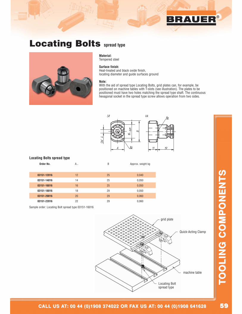
5959
®
CALL US AT: 00 44 (0)1908 374022 OR FAX US AT: 00 44 (0)1908 641628CALL US AT: 00 44 (0)1908 374022 OR FAX US AT: 00 44 (0)1908 641628
TO
OL
ING
CO
MP
ON
EN
TS
TO
OL
ING
CO
MP
ON
EN
TS
®
grid plate
Quick-Acting Clamp
machine table
Locating Boltspread type
Locating Bolts spread type
Material:Tempered steel
Surface finish:Heat-treated and black oxide finish,locating diameter and guide surfaces ground
Note:With the aid of spread type Locating Bolts, grid plates can, for example, bepositioned on machine tables with T-slots (see illustration). The plates to bepositioned must have two holes matching the spread type shaft. The continuoushexagonal socket in the spread type screw allows operation from two sides.
Order No.
03151-12016
03151-14016
03151-16016
03151-18016
03151-20016
03151-22016
A -0,01
12
14
16
18
20
22
B
25
25
25
29
29
29
Approx. weight kg
0,040
0,050
0,050
0,050
0,060
0,060
Sample order: Locating Bolt spread type 03151-16016
Locating Bolts spread type
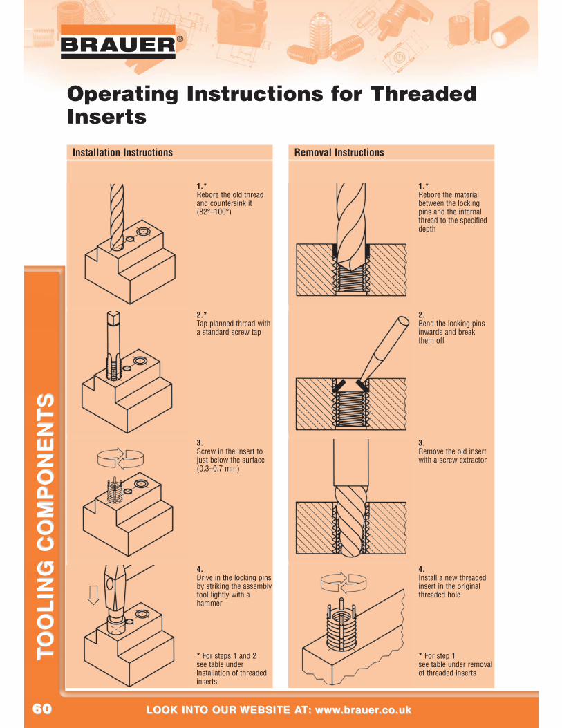
6060
®
LOOK INTO OUR WEBSITE AT: www.brauer.co.uk LOOK INTO OUR WEBSITE AT: www.brauer.co.uk
TO
OL
ING
CO
MP
ON
EN
TS
TO
OL
ING
CO
MP
ON
EN
TS
Installation Instructions Removal Instructions
1.*Rebore the old threadand countersink it(82°–100°)
2.*Tap planned thread witha standard screw tap
3.Screw in the insert tojust below the surface(0.3–0.7 mm)
4.Drive in the locking pinsby striking the assemblytool lightly with ahammer
1.*Rebore the materialbetween the lockingpins and the internalthread to the specifieddepth
2.Bend the locking pinsinwards and breakthem off
3.Remove the old insertwith a screw extractor
4.Install a new threadedinsert in the originalthreaded hole
* For step 1see table under removalof threaded inserts
* For steps 1 and 2see table underinstallation of threadedinserts
Operating Instructions for ThreadedInserts
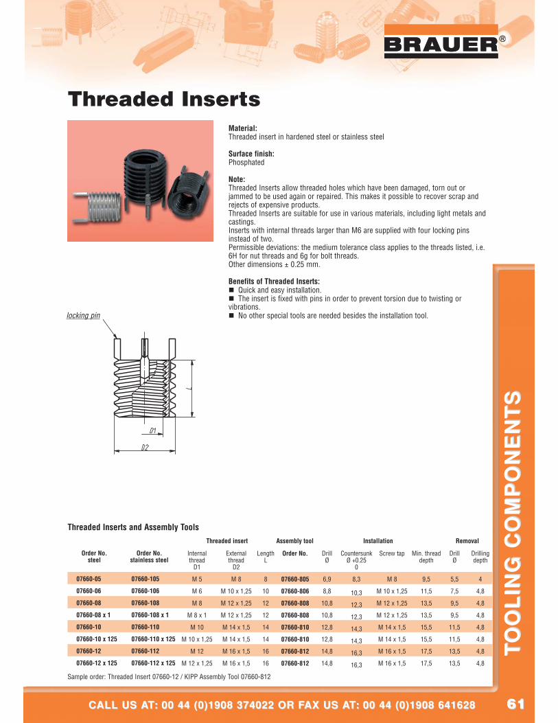
6161
®
CALL US AT: 00 44 (0)1908 374022 OR FAX US AT: 00 44 (0)1908 641628CALL US AT: 00 44 (0)1908 374022 OR FAX US AT: 00 44 (0)1908 641628
TO
OL
ING
CO
MP
ON
EN
TS
TO
OL
ING
CO
MP
ON
EN
TS
®
Threaded InsertsMaterial:Threaded insert in hardened steel or stainless steel
Surface finish:Phosphated
Note:Threaded Inserts allow threaded holes which have been damaged, torn out orjammed to be used again or repaired. This makes it possible to recover scrap andrejects of expensive products.Threaded Inserts are suitable for use in various materials, including light metals andcastings.Inserts with internal threads larger than M6 are supplied with four locking pinsinstead of two.Permissible deviations: the medium tolerance class applies to the threads listed, i.e.6H for nut threads and 6g for bolt threads.Other dimensions ± 0.25 mm.
Benefits of Threaded Inserts:� Quick and easy installation.� The insert is fixed with pins in order to prevent torsion due to twisting orvibrations.� No other special tools are needed besides the installation tool.
Internalthread
D1
M 5
M 6
M 8
M 8 x 1
M 10
M 10 x 1,25
M 12
M 12 x 1,25
Externalthread
D2
M 8
M 10 x 1,25
M 12 x 1,25
M 12 x 1,25
M 14 x 1,5
M 14 x 1,5
M 16 x 1,5
M 16 x 1,5
LengthL
8
10
12
12
14
14
16
16
Order No.
07660-805
07660-806
07660-808
07660-808
07660-810
07660-810
07660-812
07660-812
DrillØ
6,9
8,8
10,8
10,8
12,8
12,8
14,8
14,8
Countersunk Ø +0.25
0
8,3
10,3
12,3
12,3
14,3
14,3
16,3
16,3
Screw tap
M 8
M 10 x 1,25
M 12 x 1,25
M 12 x 1,25
M 14 x 1,5
M 14 x 1,5
M 16 x 1,5
M 16 x 1,5
Min. threaddepth
9,5
11,5
13,5
13,5
15,5
15,5
17,5
17,5
DrillØ
5,5
7,5
9,5
9,5
11,5
11,5
13,5
13,5
Drillingdepth
4
4,8
4,8
4,8
4,8
4,8
4,8
4,8
Order No.steel
07660-05
07660-06
07660-08
07660-08 x 1
07660-10
07660-10 x 125
07660-12
07660-12 x 125
Order No.stainless steel
07660-105
07660-106
07660-108
07660-108 x 1
07660-110
07660-110 x 125
07660-112
07660-112 x 125
Sample order: Threaded Insert 07660-12 / KIPP Assembly Tool 07660-812
Threaded Inserts and Assembly ToolsThreaded insert Installation RemovalAssembly tool
locking pin
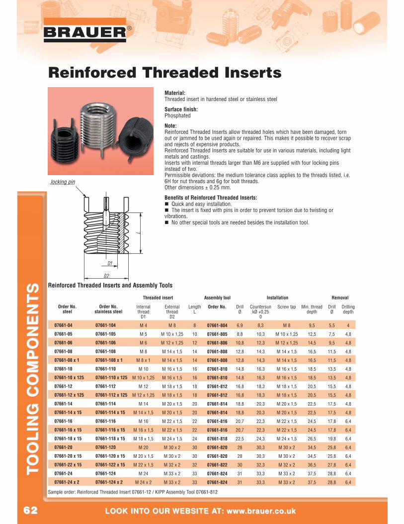
6262
®
LOOK INTO OUR WEBSITE AT: www.brauer.co.uk LOOK INTO OUR WEBSITE AT: www.brauer.co.uk
TO
OL
ING
CO
MP
ON
EN
TS
TO
OL
ING
CO
MP
ON
EN
TS
Internalthread
D1
M 4
M 5
M 6
M 8
M 8 x 1
M 10
M 10 x 1,25
M 12
M 12 x 1,25
M 14
M 14 x 1,5
M 16
M 16 x 1,5
M 18 x 1,5
M 20
M 20 x 1,5
M 22 x 1,5
M 24
M 24 x 2
Externalthread
D2
M 8
M 10 x 1,25
M 12 x 1,25
M 14 x 1,5
M 14 x 1,5
M 16 x 1,5
M 16 x 1,5
M 18 x 1,5
M 18 x 1,5
M 20 x 1,5
M 20 x 1,5
M 22 x 1,5
M 22 x 1,5
M 24 x 1,5
M 30 x 2
M 30 x 2
M 32 x 2
M 33 x 2
M 33 x 2
LengthL
8
10
12
14
14
16
16
18
18
20
20
22
22
24
30
30
32
33
33
Order No.
07661-804
07661-805
07661-806
07661-808
07661-808
07661-810
07661-810
07661-812
07661-812
07661-814
07661-814
07661-816
07661-816
07661-818
07661-820
07661-820
07661-822
07661-824
07661-824
DrillØ
6,9
8,8
10,8
12,8
12,8
14,8
14,8
16,8
16,8
18,8
18,8
20,7
20,7
22,5
28
28
30
31
31
Screw tap
M 8
M 10 x 1,25
M 12 x 1,25
M 14 x 1,5
M 14 x 1,5
M 16 x 1,5
M 16 x 1,5
M 18 x 1,5
M 18 x 1,5
M 20 x 1,5
M 20 x 1,5
M 22 x 1,5
M 22 x 1,5
M 24 x 1,5
M 30 x 2
M 30 x 2
M 32 x 2
M 33 x 2
M 33 x 2
Min. threaddepth
9,5
12,5
14,5
16,5
16,5
18,5
18,5
20,5
20,5
22,5
22,5
24,5
24,5
26,5
34,5
34,5
36,5
37,5
37,5
DrillØ
5,5
7,5
9,5
11,5
11,5
13,5
13,5
15,5
15,5
17,5
17,5
17,8
17,8
19,8
25,8
25,8
27,8
28,8
28,8
Drillingdepth
4
4,8
4,8
4,8
4,8
4,8
4,8
4,8
4,8
4,8
4,8
6,4
6,4
6,4
6,4
6,4
6,4
6,4
6,4
Order No.steel
07661-04
07661-05
07661-06
07661-08
07661-08 x 1
07661-10
07661-10 x 125
07661-12
07661-12 x 125
07661-14
07661-14 x 15
07661-16
07661-16 x 15
07661-18 x 15
07661-20
07661-20 x 15
07661-22 x 15
07661-24
07661-24 x 2
Order No.stainless steel
07661-104
07661-105
07661-106
07661-108
07661-108 x 1
07661-110
07661-110 x 125
07661-112
07661-112 x 125
07661-114
07661-114 x 15
07661-116
07661-116 x 15
07661-118 x 15
07661-120
07661-120 x 15
07661-122 x 15
07661-124
07661-124 x 2
Sample order: Reinforced Threaded Insert 07661-12 / KIPP Assembly Tool 07661-812
Reinforced Threaded Inserts and Assembly Tools
Threaded insert Installation RemovalAssembly tool
locking pin
CountersunkØ +0.25
0
8,3
10,3
12,3
14,3
14,3
16,3
16,3
18,3
18,3
20,3
20,3
22,3
22,3
24,3
30,3
30,3
32,3
33,3
33,3
Reinforced Threaded InsertsMaterial:Threaded insert in hardened steel or stainless steel
Surface finish:Phosphated
Note:Reinforced Threaded Inserts allow threaded holes which have been damaged, tornout or jammed to be used again or repaired. This makes it possible to recover scrapand rejects of expensive products.Reinforced Threaded Inserts are suitable for use in various materials, including lightmetals and castings.Inserts with internal threads larger than M6 are supplied with four locking pinsinstead of two.Permissible deviations: the medium tolerance class applies to the threads listed, i.e.6H for nut threads and 6g for bolt threads.Other dimensions ± 0.25 mm.
Benefits of Reinforced Threaded Inserts:� Quick and easy installation.� The insert is fixed with pins in order to prevent torsion due to twisting orvibrations.� No other special tools are needed besides the installation tool.
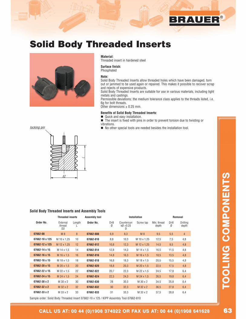
6363
®
CALL US AT: 00 44 (0)1908 374022 OR FAX US AT: 00 44 (0)1908 641628CALL US AT: 00 44 (0)1908 374022 OR FAX US AT: 00 44 (0)1908 641628
TO
OL
ING
CO
MP
ON
EN
TS
TO
OL
ING
CO
MP
ON
EN
TS
®
Solid Body Threaded InsertsMaterial:Threaded insert in hardened steel
Surface finish:Phosphated
Note:Solid Body Threaded Inserts allow threaded holes which have been damaged, tornout or jammed to be used again or repaired. This makes it possible to recover scrapand rejects of expensive products.Solid Body Threaded Inserts are suitable for use in various materials, including lightmetals and castings.Permissible deviations: the medium tolerance class applies to the threads listed, i.e.6g for bolt threads.Other dimensions ± 0.25 mm.
Benefits of Solid Body Threaded Inserts:� Quick and easy installation.� The insert is fixed with pins in order to prevent torsion due to twisting orvibrations.� No other special tools are needed besides the installation tool.
Externalthread
D2
M 8
M 10 x 1,25
M 12 x 1,25
M 14 x 1,5
M 16 x 1,5
M 18 x 1,5
M 20 x 1,5
M 22 x 1,5
M 24 x 1,5
M 30 x 2
M 32 x 2
M 33 x 2
LengthL
8
10
12
14
16
18
20
22
24
30
32
33
Order No.
07662-808
07662-810
07662-812
07662-814
07662-816
07662-818
07662-820
07662-822
07662-824
07662-830
07662-832
07662-833
DrillØ
6,9
8,8
10,8
12,8
14,8
16,8
18,8
20,7
22,5
28
30
31
Screw tap
M 8
M 10 x 1,25
M 12 x 1,25
M 14 x 1,5
M 16 x 1,5
M 18 x 1,5
M 20 x 1,5
M 22 x 1,5
M 24 x 1,5
M 30 x 2
M 32 x 2
M 33 x 2
Min. threaddepth
9,5
12,5
14,5
16,5
18,5
20,5
22,5
24,5
26,5
34,5
36,5
37,5
DrillØ
5,5
7,5
9,5
11,5
13,5
15,5
17,5
17,8
19,8
25,8
27,8
28,8
Drillingdepth
4
4,8
4,8
4,8
4,8
4,8
4,8
6,4
6,4
6,4
6,4
6,4
Order No.
07662-08
07662-10 x 125
07662-12 x 125
07662-14 x 15
07662-16 x 15
07662-18 x 15
07662-20 x 15
07662-22 x 15
07662-24 x 15
07662-30 x 2
07662-32 x 2
07662-33 x 2
Sample order: Solid Body Threaded Insert 07662-10 x 125 / KIPP Assembly Tool 07662-810
Solid Body Threaded Inserts and Assembly ToolsThreaded inserts Installation RemovalAssembly tool
locking pin
CountersunkØ +0.25
0
8,3
10,3
12,3
14,3
16,3
18,3
20,3
22,3
24,3
30,3
32,3
33,3
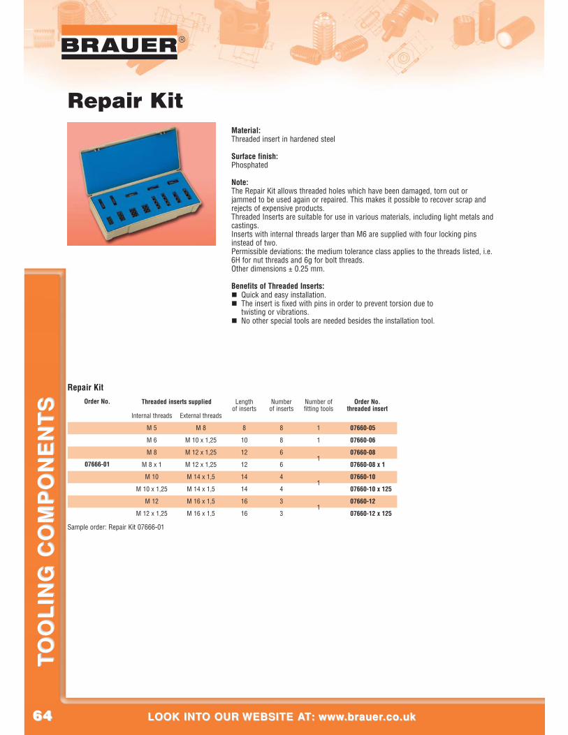
6464
®
LOOK INTO OUR WEBSITE AT: www.brauer.co.uk LOOK INTO OUR WEBSITE AT: www.brauer.co.uk
TO
OL
ING
CO
MP
ON
EN
TS
TO
OL
ING
CO
MP
ON
EN
TS
Repair KitMaterial:Threaded insert in hardened steel
Surface finish:Phosphated
Note:The Repair Kit allows threaded holes which have been damaged, torn out orjammed to be used again or repaired. This makes it possible to recover scrap andrejects of expensive products.Threaded Inserts are suitable for use in various materials, including light metals andcastings.Inserts with internal threads larger than M6 are supplied with four locking pinsinstead of two.Permissible deviations: the medium tolerance class applies to the threads listed, i.e.6H for nut threads and 6g for bolt threads.Other dimensions ± 0.25 mm.
Benefits of Threaded Inserts:� Quick and easy installation.� The insert is fixed with pins in order to prevent torsion due to
twisting or vibrations.� No other special tools are needed besides the installation tool.
Internal threads
M 5
M 6
M 8
M 8 x 1
M 10
M 10 x 1,25
M 12
M 12 x 1,25
External threads
M 8
M 10 x 1,25
M 12 x 1,25
M 12 x 1,25
M 14 x 1,5
M 14 x 1,5
M 16 x 1,5
M 16 x 1,5
Lengthof inserts
8
10
12
12
14
14
16
16
Numberof inserts
8
8
6
6
4
4
3
3
Number offitting tools
1
1
1
1
1
Order No.threaded insert
07660-05
07660-06
07660-08
07660-08 x 1
07660-10
07660-10 x 125
07660-12
07660-12 x 125
Order No.
07666-01
Sample order: Repair Kit 07666-01
Repair KitThreaded inserts supplied
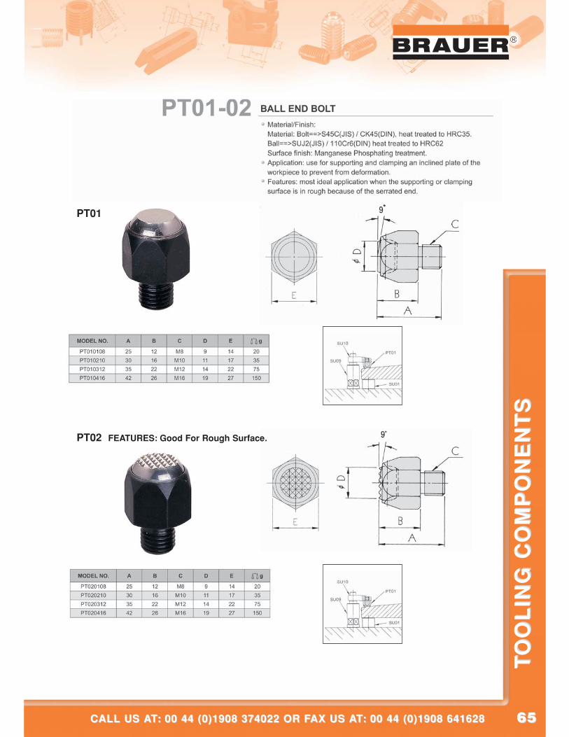
6565
®
CALL US AT: 00 44 (0)1908 374022 OR FAX US AT: 00 44 (0)1908 641628CALL US AT: 00 44 (0)1908 374022 OR FAX US AT: 00 44 (0)1908 641628
TO
OL
ING
CO
MP
ON
EN
TS
TO
OL
ING
CO
MP
ON
EN
TS
PT01
PT02 FEATURES: Good For Rough Surface.
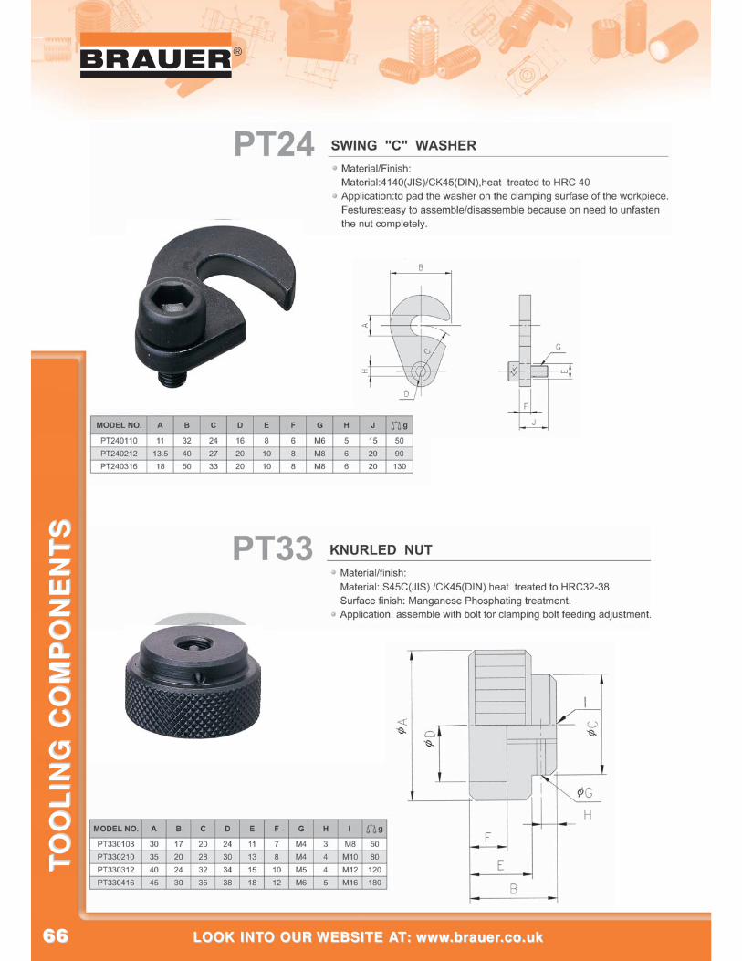
6666
®
LOOK INTO OUR WEBSITE AT: www.brauer.co.uk LOOK INTO OUR WEBSITE AT: www.brauer.co.uk
TO
OL
ING
CO
MP
ON
EN
TS
TO
OL
ING
CO
MP
ON
EN
TS
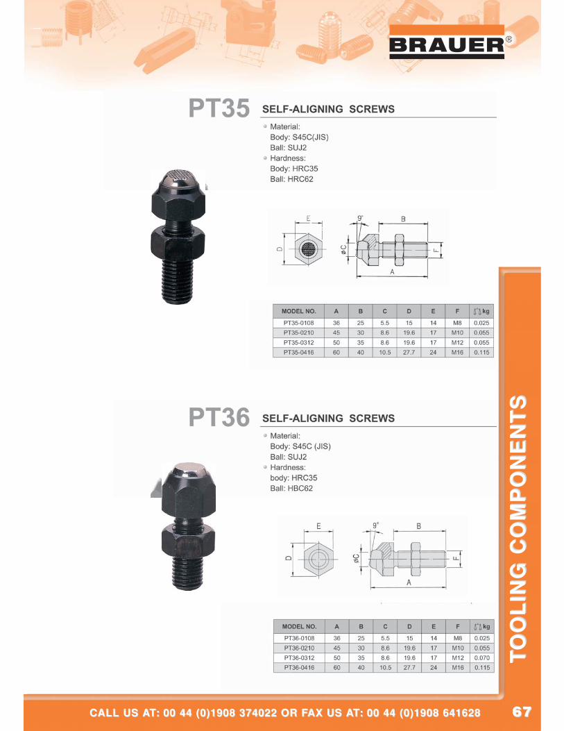
6767
®
CALL US AT: 00 44 (0)1908 374022 OR FAX US AT: 00 44 (0)1908 641628CALL US AT: 00 44 (0)1908 374022 OR FAX US AT: 00 44 (0)1908 641628
TO
OL
ING
CO
MP
ON
EN
TS
TO
OL
ING
CO
MP
ON
EN
TS
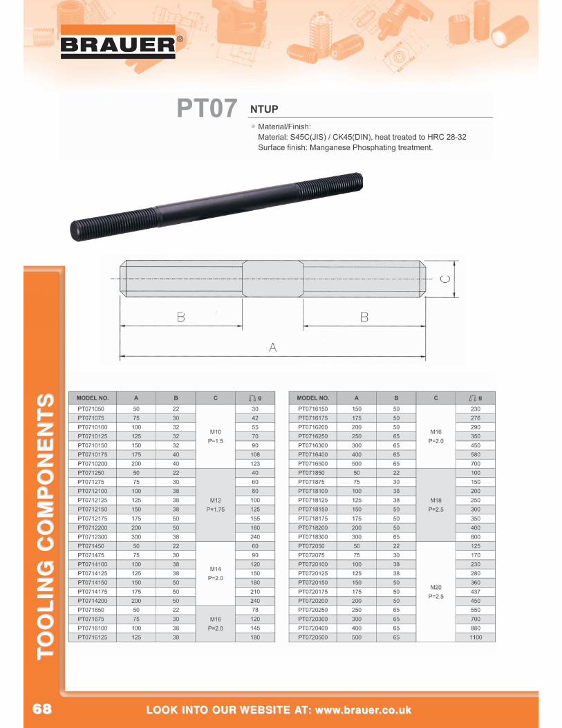
6868
®
LOOK INTO OUR WEBSITE AT: www.brauer.co.uk LOOK INTO OUR WEBSITE AT: www.brauer.co.uk
TO
OL
ING
CO
MP
ON
EN
TS
TO
OL
ING
CO
MP
ON
EN
TS
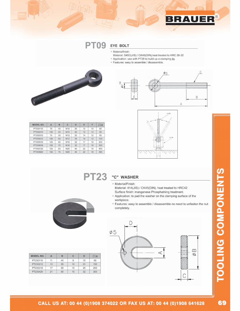
6969
®
CALL US AT: 00 44 (0)1908 374022 OR FAX US AT: 00 44 (0)1908 641628CALL US AT: 00 44 (0)1908 374022 OR FAX US AT: 00 44 (0)1908 641628
TO
OL
ING
CO
MP
ON
EN
TS
TO
OL
ING
CO
MP
ON
EN
TS
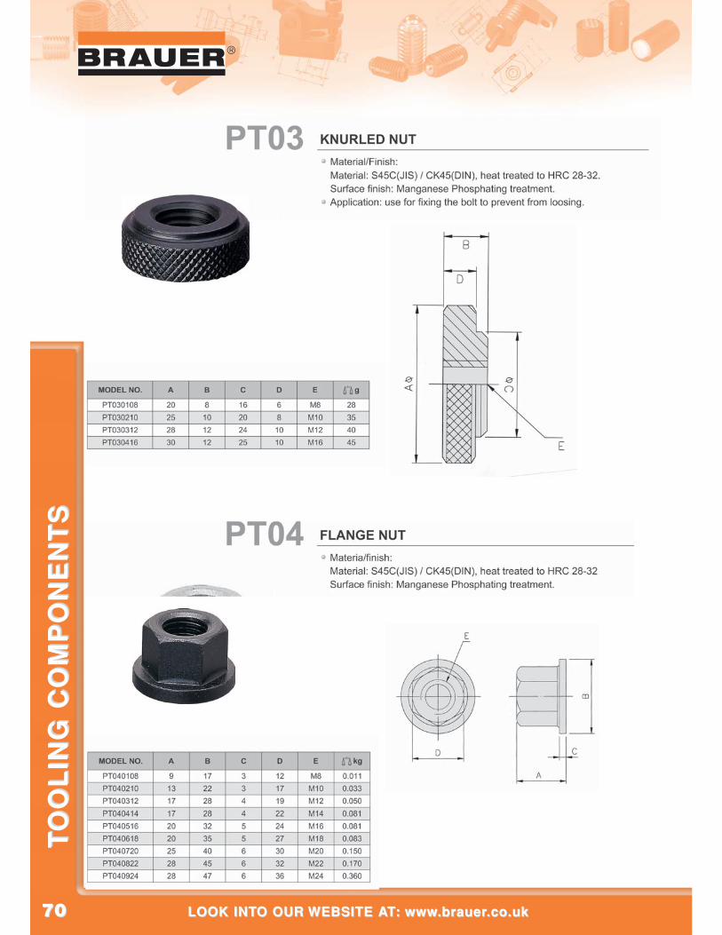
7070
®
LOOK INTO OUR WEBSITE AT: www.brauer.co.uk LOOK INTO OUR WEBSITE AT: www.brauer.co.uk
TO
OL
ING
CO
MP
ON
EN
TS
TO
OL
ING
CO
MP
ON
EN
TS
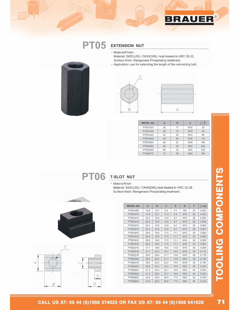
7171
®
CALL US AT: 00 44 (0)1908 374022 OR FAX US AT: 00 44 (0)1908 641628CALL US AT: 00 44 (0)1908 374022 OR FAX US AT: 00 44 (0)1908 641628
TO
OL
ING
CO
MP
ON
EN
TS
TO
OL
ING
CO
MP
ON
EN
TS
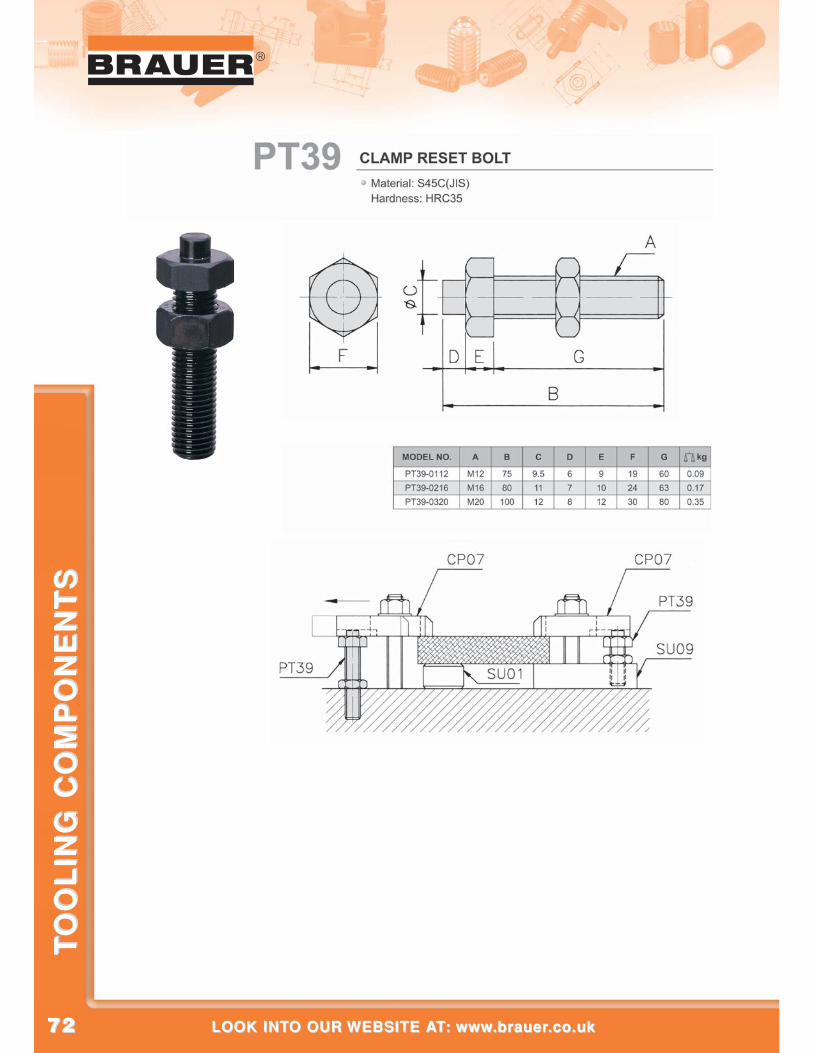
7272
®
LOOK INTO OUR WEBSITE AT: www.brauer.co.uk LOOK INTO OUR WEBSITE AT: www.brauer.co.uk
TO
OL
ING
CO
MP
ON
EN
TS
TO
OL
ING
CO
MP
ON
EN
TS
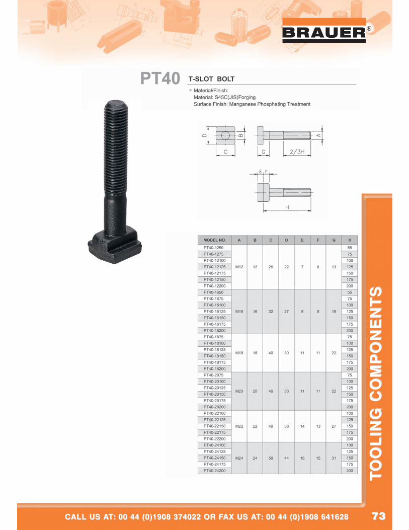
7373
®
CALL US AT: 00 44 (0)1908 374022 OR FAX US AT: 00 44 (0)1908 641628CALL US AT: 00 44 (0)1908 374022 OR FAX US AT: 00 44 (0)1908 641628
TO
OL
ING
CO
MP
ON
EN
TS
TO
OL
ING
CO
MP
ON
EN
TS
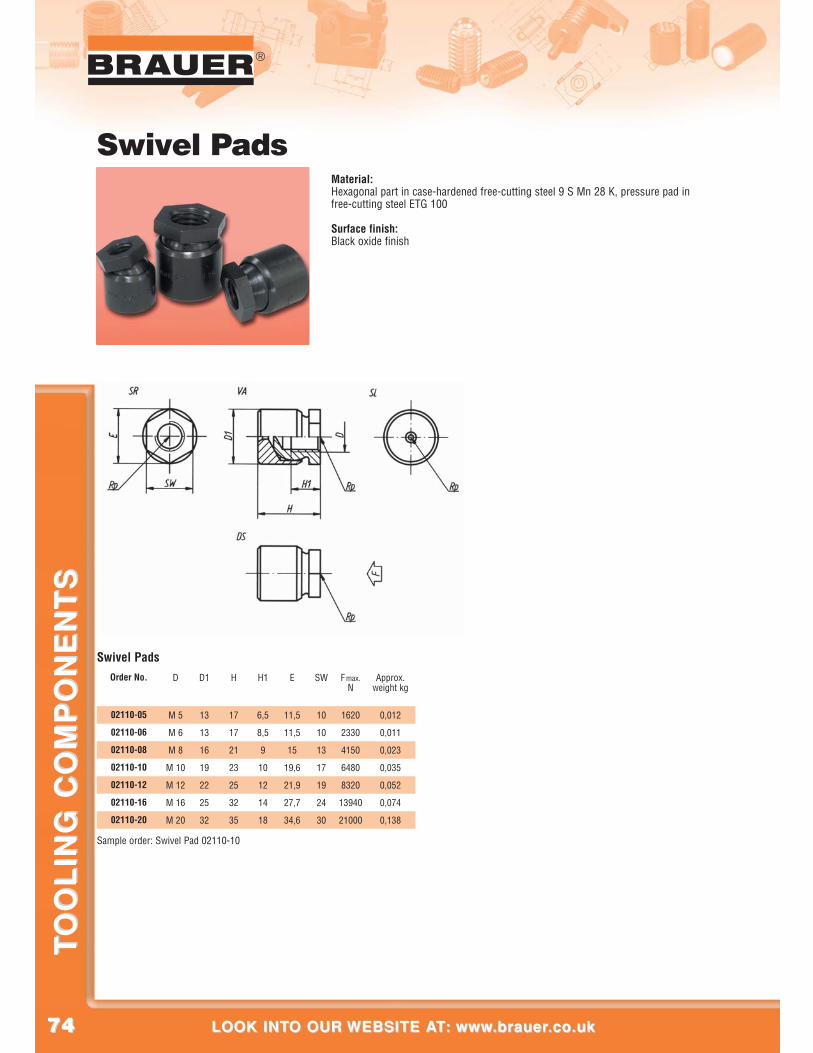
7474
®
LOOK INTO OUR WEBSITE AT: www.brauer.co.uk LOOK INTO OUR WEBSITE AT: www.brauer.co.uk
TO
OL
ING
CO
MP
ON
EN
TS
TO
OL
ING
CO
MP
ON
EN
TS
Swivel PadsMaterial:Hexagonal part in case-hardened free-cutting steel 9 S Mn 28 K, pressure pad infree-cutting steel ETG 100
Surface finish:Black oxide finish
Swivel Pads
Sample order: Swivel Pad 02110-10
D
M 5
M 6
M 8
M 10
M 12
M 16
M 20
D1
13
13
16
19
22
25
32
H
17
17
21
23
25
32
35
H1
6,5
8,5
9
10
12
14
18
Approx.weight kg
0,012
0,011
0,023
0,035
0,052
0,074
0,138
E
11,5
11,5
15
19,6
21,9
27,7
34,6
SW
10
10
13
17
19
24
30
F max.N
1620
2330
4150
6480
8320
13940
21000
Order No.
02110-05
02110-06
02110-08
02110-10
02110-12
02110-16
02110-20
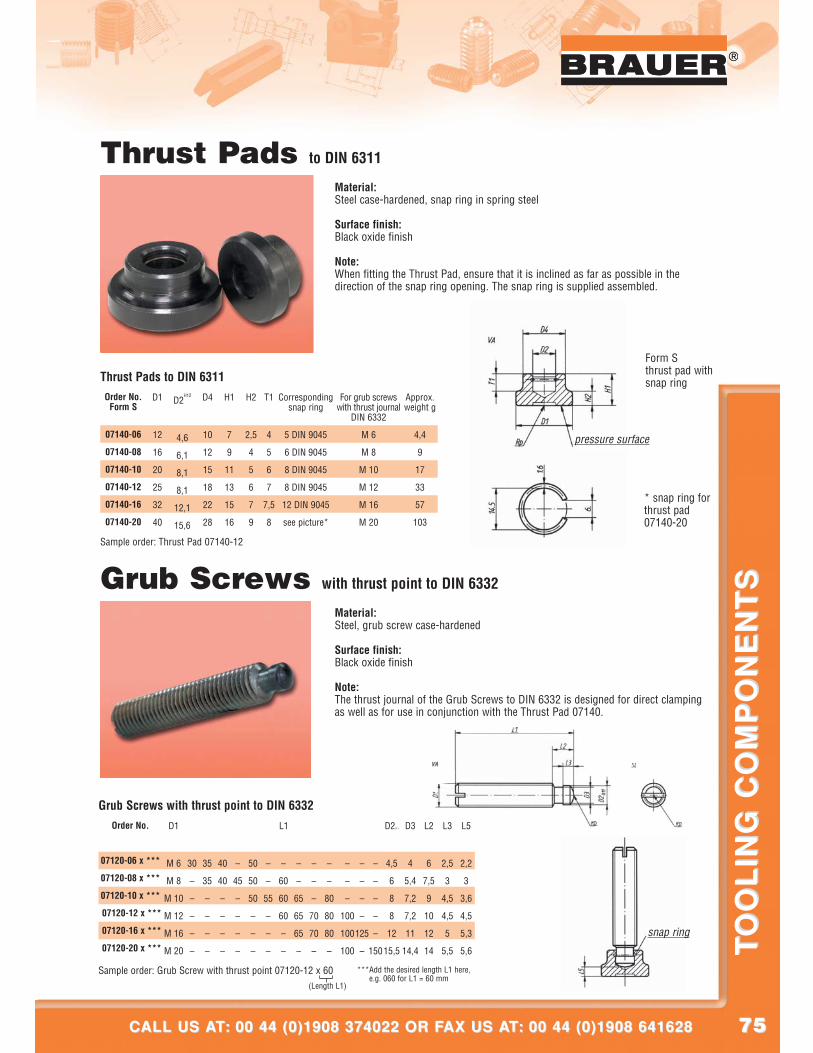
7575
®
CALL US AT: 00 44 (0)1908 374022 OR FAX US AT: 00 44 (0)1908 641628CALL US AT: 00 44 (0)1908 374022 OR FAX US AT: 00 44 (0)1908 641628
TO
OL
ING
CO
MP
ON
EN
TS
TO
OL
ING
CO
MP
ON
EN
TS
®
(Length L1)
Thrust Pads to DIN 6311
Material:Steel case-hardened, snap ring in spring steel
Surface finish:Black oxide finish
Note:When fitting the Thrust Pad, ensure that it is inclined as far as possible in thedirection of the snap ring opening. The snap ring is supplied assembled.
Grub Screws with thrust point to DIN 6332
Form Sthrust pad withsnap ring
* snap ring forthrust pad07140-20
snap ring
pressure surface
D1
12
16
20
25
32
40
D2H12
4,6
6,1
8,1
8,1
12,1
15,6
D4
10
12
15
18
22
28
H1
7
9
11
13
15
16
H2
2,5
4
5
6
7
9
T1
4
5
6
7
7,5
8
Correspondingsnap ring
5 DIN 9045
6 DIN 9045
8 DIN 9045
8 DIN 9045
12 DIN 9045
see picture*
For grub screwswith thrust journal
DIN 6332
M 6
M 8
M 10
M 12
M 16
M 20
Approx.weight g
4,4
9
17
33
57
103
Order No.Form S
07140-06
07140-08
07140-10
07140-12
07140-16
07140-20
Sample order: Thrust Pad 07140-12
Thrust Pads to DIN 6311
D1
M 6
M 8
M 10
M 12
M 16
M 20
30
–
–
–
–
–
35
35
–
–
–
–
40
40
–
–
–
–
–
45
–
–
–
–
50
50
50
–
–
–
–
–
55
–
–
–
–
60
60
60
–
–
–
–
65
65
65
–
–
–
–
70
70
–
–
–
80
80
80
–
–
–
–
100
100
100
–
–
–
–
125
–
–
–
–
–
–
150
D2h11
4,5
6
8
8
12
15,5
D3
4
5,4
7,2
7,2
11
14,4
L2
6
7,5
9
10
12
14
L3
2,5
3
4,5
4,5
5
5,5
L5
2,2
3
3,6
4,5
5,3
5,6
Order No.
07120-06 x ***
07120-08 x ***
07120-10 x ***
07120-12 x ***
07120-16 x ***
07120-20 x ***
Sample order: Grub Screw with thrust point 07120-12 x 60
Grub Screws with thrust point to DIN 6332L1
***Add the desired length L1 here,e.g. 060 for L1 = 60 mm
Material:Steel, grub screw case-hardened
Surface finish:Black oxide finish
Note:The thrust journal of the Grub Screws to DIN 6332 is designed for direct clampingas well as for use in conjunction with the Thrust Pad 07140.
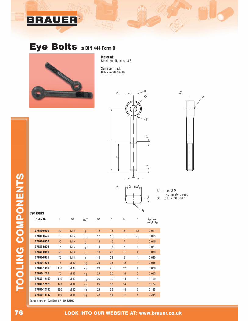
7676
®
LOOK INTO OUR WEBSITE AT: www.brauer.co.uk LOOK INTO OUR WEBSITE AT: www.brauer.co.uk
TO
OL
ING
CO
MP
ON
EN
TS
TO
OL
ING
CO
MP
ON
EN
TS
Eye Bolts to DIN 444 Form B
Material:Steel, quality class 8.8
Surface finish:Black oxide finish
U = max. 2 Pincomplete thread
X1 to DIN 76 part 1
ball
L
50
75
50
75
50
75
75
100
75
100
120
130
130
D1
M 5
M 5
M 6
M 6
M 8
M 8
M 10
M 10
M 12
M 12
M 12
M 12
M 16
D2H9
5
5
6
6
8
8
10
10
12
12
12
12
16
D3
12
12
14
14
18
18
20
20
25
25
25
25
32
B
16
16
18
18
22
22
26
26
30
30
30
36
44
S-0,2
6
6
7
7
9
9
12
12
14
14
14
14
17
R
2,5
2,5
4
4
4
4
4
4
6
6
6
6
6
Approx.weight kg
0,011
0,015
0,016
0,021
0,030
0,040
0,055
0,070
0,085
0,100
0,124
0,135
0,244
Order No.
07180-0550
07180-0575
07180-0650
07180-0675
07180-0850
07180-0875
07180-1075
07180-10100
07180-1275
07180-12100
07180-12120
07180-12130
07180-16130
Sample order: Eye Bolt 07180-12100
Eye Bolts
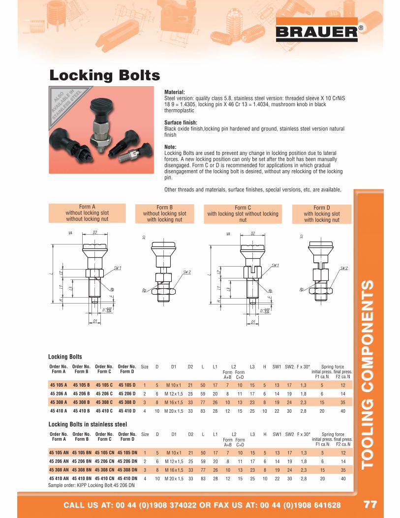
7777
®
CALL US AT: 00 44 (0)1908 374022 OR FAX US AT: 00 44 (0)1908 641628CALL US AT: 00 44 (0)1908 374022 OR FAX US AT: 00 44 (0)1908 641628
TO
OL
ING
CO
MP
ON
EN
TS
TO
OL
ING
CO
MP
ON
EN
TS
®
Locking BoltsMaterial:Steel version: quality class 5.8, stainless steel version: threaded sleeve X 10 CrNiS18 9 = 1.4305, locking pin X 46 Cr 13 = 1.4034, mushroom knob in blackthermoplastic
Surface finish:Black oxide finish,locking pin hardened and ground, stainless steel version naturalfinish
Note:Locking Bolts are used to prevent any change in locking position due to lateralforces. A new locking position can only be set after the bolt has been manuallydisengaged. Form C or D is recommended for applications in which gradualdisengagement of the locking bolt is desired, without any relocking of the lockingpin.
Other threads and materials, surface finishes, special versions, etc. are available.
Form Awithout locking slotwithout locking nut
Form Bwithout locking slot
with locking nut
Form Cwith locking slot without locking
nut
Form Dwith locking slotwith locking nut
Size
1
2
3
4
L2 Spring forceD
5
6
8
10
D1
M 10 x 1
M 12 x 1,5
M 16 x 1,5
M 20 x 1,5
D2
21
25
33
33
L
50
59
77
83
L1
17
20
26
28
FormA+B
7
8
10
12
FormC+D
10
11
13
15
L3
15
17
23
25
H
5
6
8
10
SW1
13
14
19
22
SW2
17
19
24
30
F x 30°
1,3
1,8
2,3
2,8
initial press.F1 ca.N
5
6
15
20
final press.F2 ca.N
12
14
35
40
Order No.Form A
45 105 A
45 206 A
45 308 A
45 410 A
Order No.Form B
45 105 B
45 206 B
45 308 B
45 410 B
Order No.Form C
45 105 C
45 206 C
45 308 C
45 410 C
Order No.Form D
45 105 D
45 206 D
45 308 D
45 410 D
Locking Bolts
Size
1
2
3
4
L2 Spring forceD
5
6
8
10
D1
M 10 x 1
M 12 x 1,5
M 16 x 1,5
M 20 x 1,5
D2
21
25
33
33
L
50
59
77
83
L1
17
20
26
28
FormA+B
7
8
10
12
FormC+D
10
11
13
15
L3
15
17
23
25
H
5
6
8
10
SW1
13
14
19
22
SW2
17
19
24
30
F x 30°
1,3
1,8
2,3
2,8
initial press.F1 ca.N
5
6
15
20
final press.F2 ca.N
12
14
35
40
Order No.Form A
45 105 AN
45 206 AN
45 308 AN
45 410 AN
Order No.Form B
45 105 BN
45 206 BN
45 308 BN
45 410 BN
Order No.Form C
45 105 CN
45 206 CN
45 308 CN
45 410 CN
Order No.Form D
45 105 DN
45 206 DN
45 308 DN
45 410 DN
Locking Bolts in stainless steel
Sample order: KIPP Locking Bolt 45 206 DN
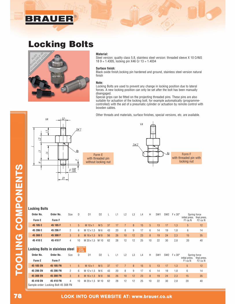
7878
®
LOOK INTO OUR WEBSITE AT: www.brauer.co.uk LOOK INTO OUR WEBSITE AT: www.brauer.co.uk
TO
OL
ING
CO
MP
ON
EN
TS
TO
OL
ING
CO
MP
ON
EN
TS
Form Ewith threaded pin
without locking nut
Form Fwith threaded pin with
locking nut
Locking BoltsMaterial:Steel version: quality class 5.8, stainless steel version: threaded sleeve X 10 CrNiS18 9 = 1.4305, locking pin X46 Cr 13 = 1.4034
Surface finish:Black oxide finish,locking pin hardened and ground, stainless steel version naturalfinish
Note:Locking Bolts are used to prevent any change in locking position due to lateralforces. A new locking position can only be set after the bolt has been manuallydisengaged.Special grips can be fitted on the projecting threaded pins. These pins are alsosuitable for actuation of the locking bolt, for example automatically (programme-controlled) with the aid of a pneumatic cylinder or actuation by remote control withbowden cables.
Other threads and materials, surface finishes, special versions, etc. are available.
Size
1
2
3
4
Spring forceD
5
6
8
10
D1
M 10 x 1
M 12 x 1,5
M 16 x 1,5
M 20 x 1,5
D2
M 5
M 6
M 8
M 10
L
37
43
56
62
L1
17
20
26
28
L2
7
8
10
12
L3
8
9
12
12
L4
15
17
23
25
H
5
6
8
10
SW1
13
14
19
22
SW2
17
19
24
30
F x 30°
1,3
1,8
2,3
2,8
initial press.F1 ca.N
5
6
15
20
final press.F2 ca.N
12
14
35
40
Order No.
Form E
45 105 EN
45 206 EN
45 308 EN
45 410 EN
Order No.
Form F
45 105 FN
45 206 FN
45 308 FN
45 410 FN
Locking Bolts in stainless steel
Size
1
2
3
4
Spring forceD
5
6
8
10
D1
M 10 x 1
M 12 x 1,5
M 16 x 1,5
M 20 x 1,5
D2
M 5
M 6
M 8
M 10
L
37
43
56
62
L1
17
20
26
28
L2
7
8
10
12
L3
8
9
12
12
L4
15
17
23
25
H
5
6
8
10
SW1
13
14
19
22
SW2
17
19
24
30
F x 30°
1,3
1,8
2,3
2,8
initial press.F1 ca.N
5
6
15
20
final press.F2 ca.N
12
14
35
40
Order No.
Form E
45 105 E
45 206 E
45 308 E
45 410 E
Order No.
Form F
45 105 F
45 206 F
45 308 F
45 410 F
Locking Bolts
Sample order: Locking Bolt 45 308 FN
STAINLESSSTEEL
OPTION
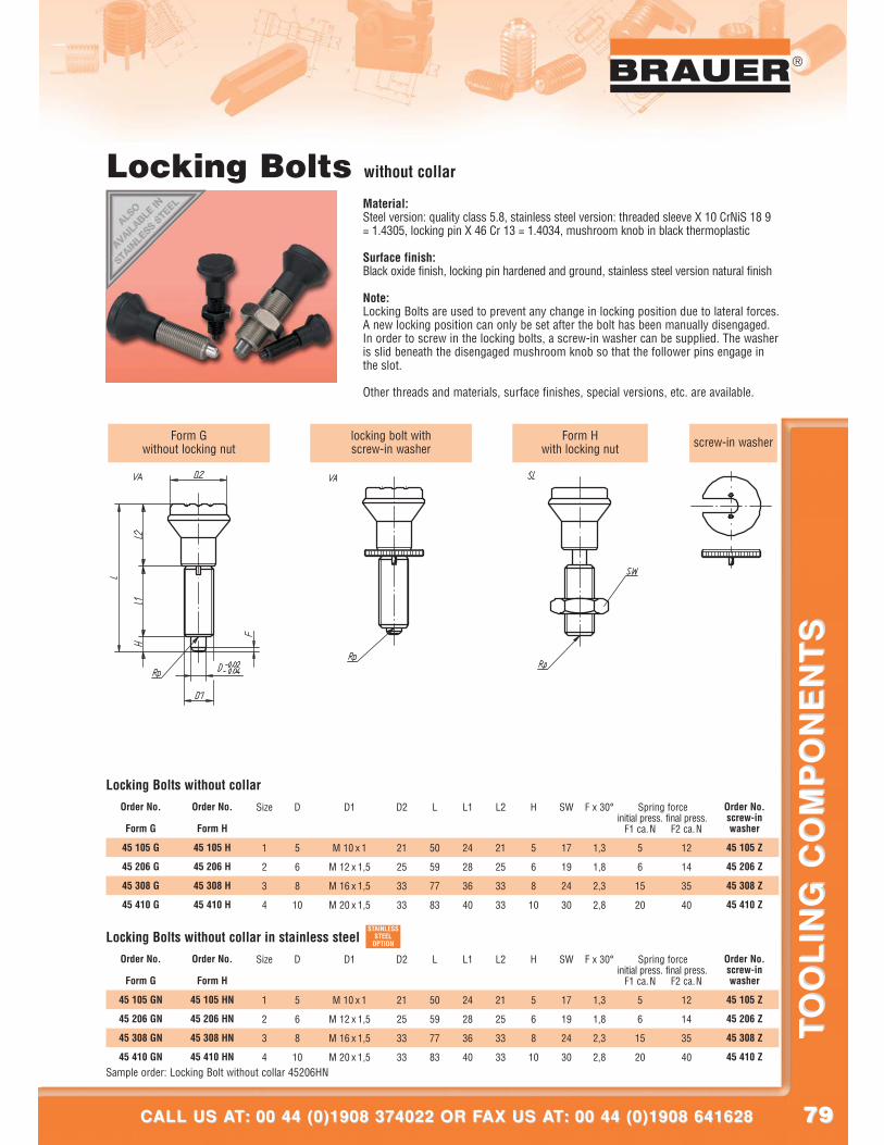
7979
®
CALL US AT: 00 44 (0)1908 374022 OR FAX US AT: 00 44 (0)1908 641628CALL US AT: 00 44 (0)1908 374022 OR FAX US AT: 00 44 (0)1908 641628
TO
OL
ING
CO
MP
ON
EN
TS
TO
OL
ING
CO
MP
ON
EN
TS
Form Gwithout locking nut
Form Hwith locking nut screw-in washerlocking bolt with
screw-in washer
Locking Bolts without collar
Material:Steel version: quality class 5.8, stainless steel version: threaded sleeve X 10 CrNiS 18 9= 1.4305, locking pin X 46 Cr 13 = 1.4034, mushroom knob in black thermoplastic
Surface finish:Black oxide finish, locking pin hardened and ground, stainless steel version natural finish
Note:Locking Bolts are used to prevent any change in locking position due to lateral forces.A new locking position can only be set after the bolt has been manually disengaged.In order to screw in the locking bolts, a screw-in washer can be supplied. The washeris slid beneath the disengaged mushroom knob so that the follower pins engage inthe slot.
Other threads and materials, surface finishes, special versions, etc. are available.
Size
1
2
3
4
Spring forceD
5
6
8
10
D1
M 10 x 1
M 12 x 1,5
M 16 x 1,5
M 20 x 1,5
D2
21
25
33
33
L
50
59
77
83
L1
24
28
36
40
L2
21
25
33
33
H
5
6
8
10
SW
17
19
24
30
F x 30°
1,3
1,8
2,3
2,8
initial press.F1 ca.N
5
6
15
20
final press.F2 ca.N
12
14
35
40
Order No.
Form G
45 105 GN
45 206 GN
45 308 GN
45 410 GN
Order No.
Form H
45 105 HN
45 206 HN
45 308 HN
45 410 HN
Order No.screw-in washer
45 105 Z
45 206 Z
45 308 Z
45 410 Z
Locking Bolts without collar in stainless steel
Size
1
2
3
4
Spring forceD
5
6
8
10
D1
M 10 x 1
M 12 x 1,5
M 16 x 1,5
M 20 x 1,5
D2
21
25
33
33
L
50
59
77
83
L1
24
28
36
40
L2
21
25
33
33
H
5
6
8
10
SW
17
19
24
30
F x 30°
1,3
1,8
2,3
2,8
initial press.F1 ca.N
5
6
15
20
final press.F2 ca.N
12
14
35
40
Order No.
Form G
45 105 G
45 206 G
45 308 G
45 410 G
Order No.
Form H
45 105 H
45 206 H
45 308 H
45 410 H
Order No.screw-in washer
45 105 Z
45 206 Z
45 308 Z
45 410 Z
Locking Bolts without collar
Sample order: Locking Bolt without collar 45206HN
STAINLESSSTEEL
OPTION
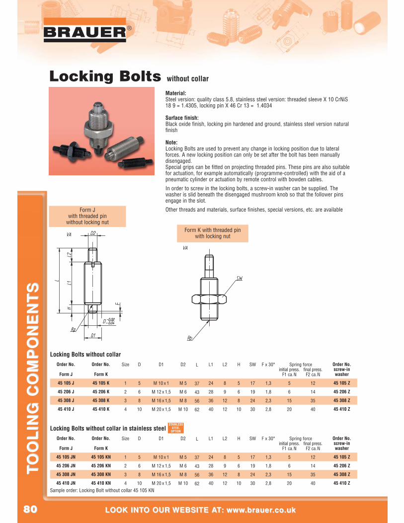
8080
®
LOOK INTO OUR WEBSITE AT: www.brauer.co.uk LOOK INTO OUR WEBSITE AT: www.brauer.co.uk
TO
OL
ING
CO
MP
ON
EN
TS
TO
OL
ING
CO
MP
ON
EN
TS
Form Jwith threaded pin
without locking nutForm K with threaded pin
with locking nut
Locking Bolts without collar
Material:Steel version: quality class 5.8, stainless steel version: threaded sleeve X 10 CrNiS18 9 = 1.4305, locking pin X 46 Cr 13 = 1.4034
Surface finish:Black oxide finish, locking pin hardened and ground, stainless steel version naturalfinish
Note:Locking Bolts are used to prevent any change in locking position due to lateralforces. A new locking position can only be set after the bolt has been manuallydisengaged.Special grips can be fitted on projecting threaded pins. These pins are also suitablefor actuation, for example automatically (programme-controlled) with the aid of apneumatic cylinder or actuation by remote control with bowden cables.
In order to screw in the locking bolts, a screw-in washer can be supplied. Thewasher is slid beneath the disengaged mushroom knob so that the follower pinsengage in the slot.
Other threads and materials, surface finishes, special versions, etc. are available
Size
1
2
3
4
Spring forceD
5
6
8
10
D1
M 10 x 1
M 12 x 1,5
M 16 x 1,5
M 20 x 1,5
D2
M 5
M 6
M 8
M 10
L
37
43
56
62
L1
24
28
36
40
L2
8
9
12
12
H
5
6
8
10
SW
17
19
24
30
F x 30°
1,3
1,8
2,3
2,8
initial press.F1 ca.N
5
6
15
20
final press.F2 ca.N
12
14
35
40
Order No.
Form J
45 105 JN
45 206 JN
45 308 JN
45 410 JN
Order No.
Form K
45 105 KN
45 206 KN
45 308 KN
45 410 KN
Order No.screw-inwasher
45 105 Z
45 206 Z
45 308 Z
45 410 Z
Locking Bolts without collar in stainless steel
Size
1
2
3
4
Spring forceD
5
6
8
10
D1
M 10 x 1
M 12 x 1,5
M 16 x 1,5
M 20 x 1,5
D2
M 5
M 6
M 8
M 10
L
37
43
56
62
L1
24
28
36
40
L2
8
9
12
12
H
5
6
8
10
SW
17
19
24
30
F x 30°
1,3
1,8
2,3
2,8
initial press.F1 ca.N
5
6
15
20
final press.F2 ca.N
12
14
35
40
Order No.
Form J
45 105 J
45 206 J
45 308 J
45 410 J
Order No.
Form K
45 105 K
45 206 K
45 308 K
45 410 K
Order No.screw-inwasher
45 105 Z
45 206 Z
45 308 Z
45 410 Z
Locking Bolts without collar
Sample order: Locking Bolt without collar 45 105 KN
STAINLESSSTEEL
OPTION
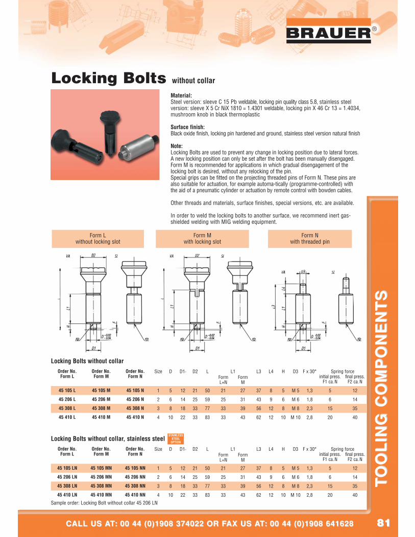
8181
®
CALL US AT: 00 44 (0)1908 374022 OR FAX US AT: 00 44 (0)1908 641628CALL US AT: 00 44 (0)1908 374022 OR FAX US AT: 00 44 (0)1908 641628
TO
OL
ING
CO
MP
ON
EN
TS
TO
OL
ING
CO
MP
ON
EN
TS
Form Lwithout locking slot
Form Mwith locking slot
Form Nwith threaded pin
Locking Bolts without collar
Material:Steel version: sleeve C 15 Pb weldable, locking pin quality class 5.8, stainless steelversion: sleeve X 5 Cr NiX 1810 = 1.4301 weldable, locking pin X 46 Cr 13 = 1.4034,mushroom knob in black thermoplastic
Surface finish:Black oxide finish, locking pin hardened and ground, stainless steel version natural finish
Note:Locking Bolts are used to prevent any change in locking position due to lateral forces.A new locking position can only be set after the bolt has been manually disengaged.Form M is recommended for applications in which gradual disengagement of thelocking bolt is desired, without any relocking of the pin.Special grips can be fitted on the projecting threaded pins of Form N. These pins arealso suitable for actuation, for example automa-tically (programme-controlled) withthe aid of a pneumatic cylinder or actuation by remote control with bowden cables.
Other threads and materials, surface finishes, special versions, etc. are available.
In order to weld the locking bolts to another surface, we recommend inert gas-shielded welding with MIG welding equipment.
Size
1
2
3
4
L1 Spring forceD
5
6
8
10
D1h9
12
14
18
22
D2
21
25
33
33
L
50
59
77
83
FormL+N
21
25
33
33
FormM
27
31
39
43
L3
37
43
56
62
L4
8
9
12
12
H
5
6
8
10
D3
M 5
M 6
M 8
M 10
F x 30°
1,3
1,8
2,3
2,8
initial press.F1 ca.N
5
6
15
20
final press.F2 ca.N
12
14
35
40
Order No.Form L
45 105 LN
45 206 LN
45 308 LN
45 410 LN
Order No.Form M
45 105 MN
45 206 MN
45 308 MN
45 410 MN
Order No.Form N
45 105 NN
45 206 NN
45 308 NN
45 410 NN
Locking Bolts without collar, stainless steel
Size
1
2
3
4
L1 Spring forceD
5
6
8
10
D1h9
12
14
18
22
D2
21
25
33
33
L
50
59
77
83
FormL+N
21
25
33
33
FormM
27
31
39
43
L3
37
43
56
62
L4
8
9
12
12
H
5
6
8
10
D3
M 5
M 6
M 8
M 10
F x 30°
1,3
1,8
2,3
2,8
initial press.F1 ca.N
5
6
15
20
final press.F2 ca.N
12
14
35
40
Order No.Form L
45 105 L
45 206 L
45 308 L
45 410 L
Order No.Form M
45 105 M
45 206 M
45 308 M
45 410 M
Order No.Form N
45 105 N
45 206 N
45 308 N
45 410 N
Locking Bolts without collar
Sample order: Locking Bolt without collar 45 206 LN
STAINLESSSTEEL
OPTION
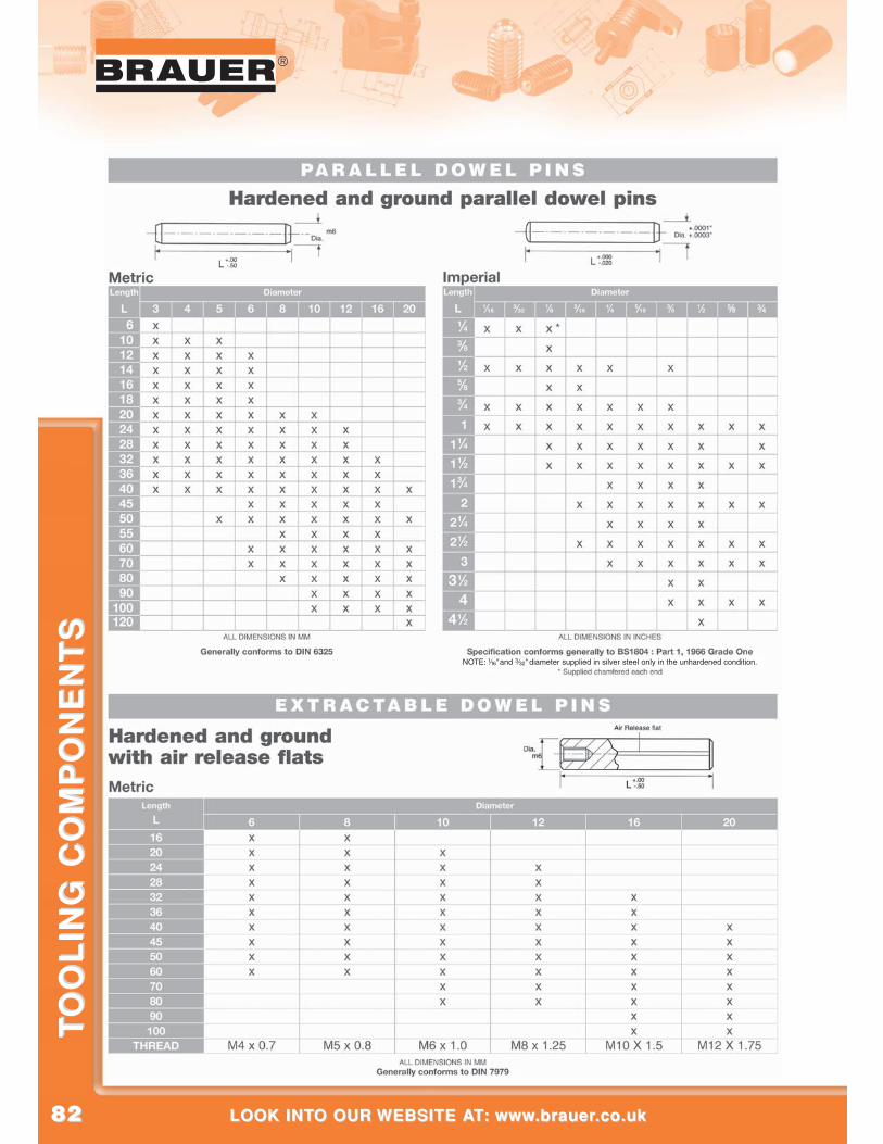
8282
®
LOOK INTO OUR WEBSITE AT: www.brauer.co.uk LOOK INTO OUR WEBSITE AT: www.brauer.co.uk
TO
OL
ING
CO
MP
ON
EN
TS
TO
OL
ING
CO
MP
ON
EN
TS
NOTE: !/16” and #/32” diameter supplied in silver steel only in the unhardened condition.
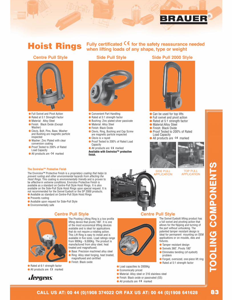
8383
®
CALL US AT: 00 44 (0)1908 374022 OR FAX US AT: 00 44 (0)1908 641628CALL US AT: 00 44 (0)1908 374022 OR FAX US AT: 00 44 (0)1908 641628
TO
OL
ING
CO
MP
ON
EN
TS
TO
OL
ING
CO
MP
ON
EN
TS
Centre Pull Style
Hoist Rings Fully certificated for the safety reassurance neededwhen lifting loads of any shape, type or weight
The Pivoting Lifting Ring is a low profilelifting device that pivots 180˚. It is oneof the most economical lifting devicesavailable and is ideal for applicationsthat do not require a rotating action.This Lift Ring is easy to install and isavailable in five sizes. Load ratings rangefrom 900Kg - 9,000Kg. The product ismanufactured from alloy steel, heattreated and magnafluxed.● Base: Precision machined alloy steel● Ring: Alloy steel forging, heat treated,
magnafluxed and certified● Finish: Black oxide
● Rated at 6:1 strength factor● All products are marked
● Can be used for top lifts● Full swivel and pivot action● Rated at 5:1 strength factor● Material:Alloy Steel● Finish: Black Oxide● Proof Tested to 200% of Rated
Load Capacity● All products are marked
● Full Swivel and Pivot Action● Rated at 5:1 Strength Factor● Material: Alloy Steel● Finish: Black Oxide (Except
Washer)● Clevis, Bolt, Pins, Base, Washer
and Bushing are magnetic particleinspected
● Washer: Zinc Plated with clearconversion coating
● Proof Tested to 200% of RatedLoad Capacity
● All products are marked
● Convenient Part Handling● Rated at 5:1 strength factor● Bushing: Zinc plated silver passivate● Material: Alloy Steel● Finish: Black Oxide● Clevis, Ring, Bushing and Cap Screw
are magnetic particle inspected● Clevis is x-rayed● Proof Tested to 200% of Rated Load
Capacity● All products are markedAvailable with Envirolox™ protectivefinish.
Centre Pull Style Side Pull Style Side Pull 2000 Style
The Envirolox™ Protective FinishThe Envirolox™ Protective Finish is a proprietary coating that helps toprevent rusting and other environmental hazards from affecting theHoist Rings. This coating is environmentally friendly and is proven tobe effective in extreme conditions. Envirolox Protective Finish isavailable as a standard on Centre-Pull Style Hoist Rings. It is alsoavailable on the Side-Pull Style Hoist Rings upon special request. It isnot recommended for the Swivel Eyebolt or the SP 2000 products.● Available as standard on Centre-Pull Style Hoist Rings● Prevents rusting● Available upon request for Side-Pull Style● Environmentally safe
SIDE PULLAPPLICATION
TOP PULLAPPLICATION
Centre Pull StyleThe Swivel Eyebolt lifting product hasa full swivel and pivoting action thatallows for the flipping and turning ofthe part without unhooking. Thepatented tamper resistant design isideal for permanent mounting on OEMapplications or on moulds, dies andfixtures.● Tamper resistant design● Swivels 360˚, Pivots 180˚● Eliminates bending (of eyebolt)
problem● Forged, oversized, one-piece lift ring● Rated at 5:1 strength factor
● Load capacities to 2000Kg● Economically priced● Material: Alloy steel or 316 stainless steel● Finish: Black oxide or passivated (SS)● All products are marked
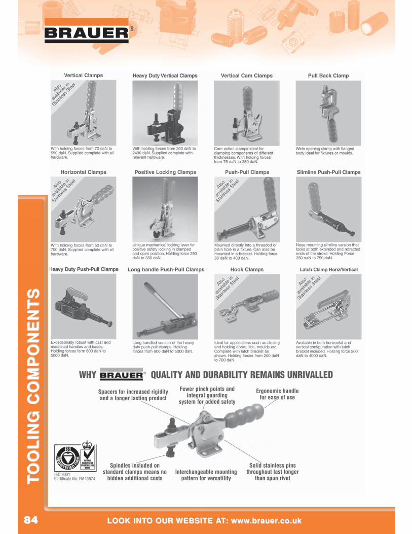
8484
®
LOOK INTO OUR WEBSITE AT: www.brauer.co.uk LOOK INTO OUR WEBSITE AT: www.brauer.co.uk
TO
OL
ING
CO
MP
ON
EN
TS
TO
OL
ING
CO
MP
ON
EN
TS
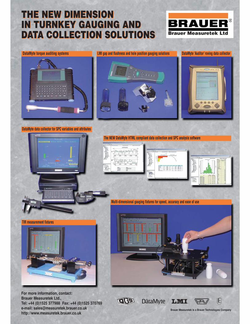
THE NEW DIMENSION IN TURNKEY GAUGING ANDDATA COLLECTION SOLUTIONS
THE NEW DIMENSION IN TURNKEY GAUGING ANDDATA COLLECTION SOLUTIONS
DataMyte torque auditing systems LMI gap and flushness and hole position gauging solutions
DataMyte data collector for SPC variables and attributes
The NEW DataMyte HTML compliant data collection and SPC analysis software
TIR measurement fixtures
Multi-dimensional gauging fixtures for speed, accuracy and ease of use
DataMyte ‘Auditor’ roving data collector
For more information, contact:Brauer Measuretek Ltd., Tel: +44 (0)1525 377988 Fax: +44 (0)1525 370769e-mail: [email protected] http://www.measuretek.brauer.co.uk
Brauer Measuretek is a Brauer Technologies Company
Brauer Measuretek Ltd
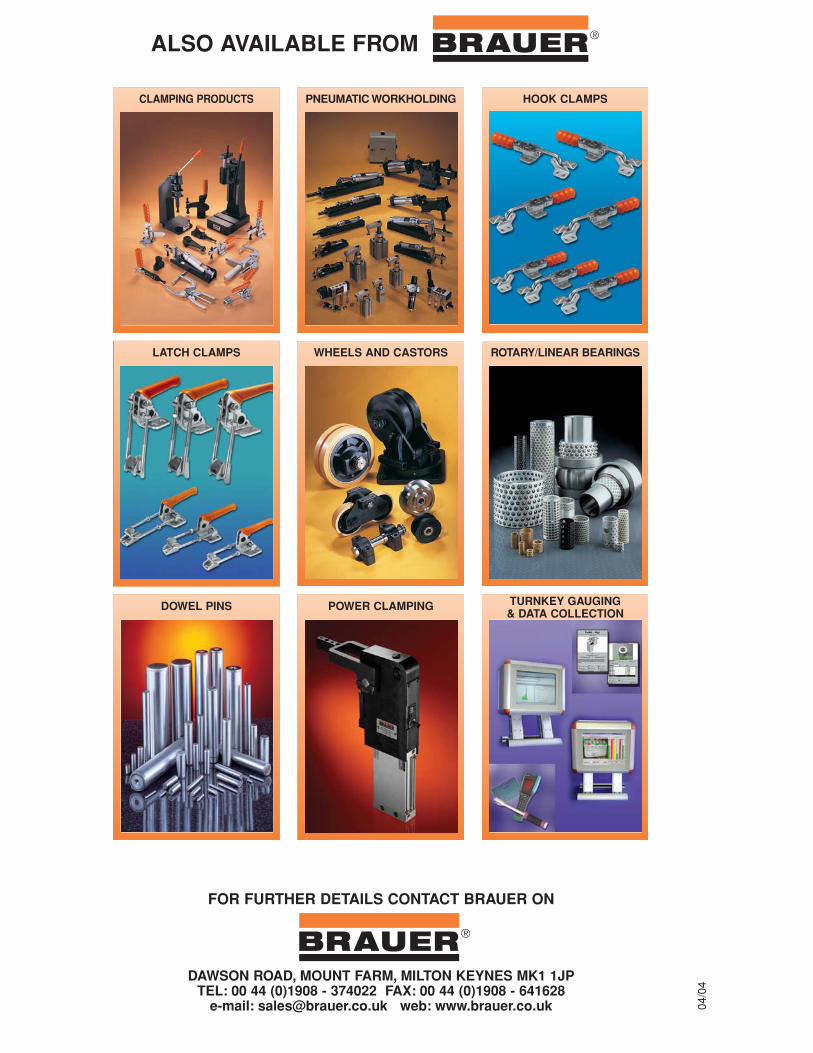
ALSO AVAILABLE FROM BRAUER
DAWSON ROAD, MOUNT FARM, MILTON KEYNES MK1 1JPTEL: 00 44 (0)1908 - 374022 FAX: 00 44 (0)1908 - 641628
e-mail: [email protected] web: www.brauer.co.uk
®
FOR FURTHER DETAILS CONTACT BRAUER ON
®
04/0
4
DOWEL PINS
PNEUMATIC WORKHOLDING HOOK CLAMPS
LATCH CLAMPS WHEELS AND CASTORS ROTARY/LINEAR BEARINGS
CLAMPING PRODUCTS
POWER CLAMPING TURNKEY GAUGING& DATA COLLECTION