Embed Size (px)
Citation preview

Tool Support for Object-OrientedCooperative Design:
Gesture Based Modeling on anElectronic Whiteboard
COT/2-45-V1.0
C
O T
*
Centre for Object Technology

Centre forObject Technology
The Centre for Object Technology (COT) is athree year project concerned with research,application and implementation of objecttechnology in Danish companies. The project isfinancially supported by The Danish NationalCentre for IT-Research (CIT) and the DanishMinistry of Industry.
Participants are:Maersk Line, Maersk Training Centre, Bang &Olufsen, WM-data, Rambøll, Danfoss, SystematicSoftware Engineering, Odense Steel Shipyard, A.P.Møller, University of Aarhus, Odense University,University of Copenhagen, Danish TechnologicalInstitute and Danish Maritime Institute
Revision history: 25/4 2000 Final Version
Author(s): Christian Heide Damm, Klaus Marius Hansen, Michael Thomsen
Status: Final
Publication: Public
Summary:
© Copyright 2000 Christian Heide Damm, Klaus Marius Hansen, Michael Thomsen
Modeling is important in object-oriented software development.Although a number of Computer Aided Software Engineering(CASE) tools are available, and even though some are technicallyadvanced, few developers use them. This paper describes ourattempt to examine the requirements needed to provide tool supportfor the development process, and describes and evaluates a tool,Knight, which has been developed based on these requirements.The tool is based on a direct, whiteboard-like interaction achievedusing gesture input on a large electronic whiteboard. So far theevaluations have beensuccessful and the tool shows the potential of greatly enhancingcurrent support for object-oriented modeling.
This paper also appears in:Proceedings of CHI'2000, April 1-6, The Hague, The Netherlands.

Tool Support for Cooperative Object-Oriented Design:Gesture Based Modeling on an Electronic Whiteboard
&KULVWLDQ�+HLGH�'DPP��.ODXV�0DULXV�+DQVHQ��0LFKDHO�7KRPVHQDepartment of Computer Science, University of Aarhus
Aabogade 34, 8200 Aarhus N, Denmark{damm, marius, miksen}@daimi.au.dk
ABSTRACTModeling is important in object-oriented software develop-ment. Although a number of Computer Aided SoftwareEngineering (CASE) tools are available, and even thoughsome are technically advanced, few developers use them.This paper describes our attempt to examine therequirements needed to provide tool support for thedevelopment process, and describes and evaluates a tool,Knight, which has been developed based on theserequirements. The tool is based on a direct, whiteboard-likeinteraction achieved using gesture input on a largeelectronic whiteboard. So far the evaluations have beensuccessful and the tool shows the potential of greatlyenhancing current support for object-oriented modeling.
KEYWORDSGesture input, electronic whiteboards, cooperative design,object-oriented modeling, user study, CASE tools.
INTRODUCTIONSoftware developers use models to develop object-orientedsoftware. In the early stages of a software developmentproject, developers focus on understanding the part of theworld that the computer system should support. Throug-hout the project, they represent their understanding in theform of models. The models are not only used in order tounderstand and discuss the world, but are also implementedin code and thus form an important part of the finalsoftware system.
A variety of Computer Aided Software Engineering(CASE) tools have been created to support the developers’work throughout the development process [12]. However,in practice these tools are supplemented with whiteboards,especially in creative phases of development.
The most appealing aspects of whiteboards are their ease ofuse and their flexibility. Whiteboards require no specialskills, they do not hamper the creativity of the user, andthey can be used for a variety of tasks. Their many
advantages aside, for most development projects white-boards are not enough. Capturing diagrams electronicallywith CASE tools facilitates code generation, documen-tation, and allows developers much more flexibility inediting and changing the diagrams. The conflicting advan-tages and disadvantages of whiteboards and CASE toolscan lead to frustrating and time consuming switchesbetween the two technologies. Our goal is to design a toolthat offers the best of both worlds.
Paper StructureThe next section presents the motivation for our design. Wethen discuss two user studies from which we derive a set ofdesign implications. We describe the Knight tool wedeveloped based on these observations, and present anevaluation of the tool. Finally, we discuss directions forfuture research and draw our conclusions.
BACKGROUNDUse of whiteboards has been studied in various contextsincluding meeting rooms [9][15], classrooms [1], andpersonal offices [17]. Whiteboards are very simple to useand many activities are ideally suited for this simple inter-action. Computational augmentation [24] can potentiallysolve problems with whiteboards such as lack of space andefficient editing facilities. We are concerned with the use ofwhiteboards in a specific work practice, cooperative object-oriented modeling, and the potential use of augmentationin that setting.
CASE tools seek to support software developmenttechniques such as diagramming, code generation, anddocumentation. Nevertheless, adoption of CASE tools inorganizations is slow and partial [5][8]. A main reason isthat current CASE tools are targeted at technically-orientedmethods rather than user-oriented processes. In particular,CASE tools are weak in supporting creativity, ideageneration, and problem solving [7].
The 7LYROL system [20][16] inspired us and was a startingpoint for our work. It is designed to support small, informalmeetings on an electronic whiteboard. The similarity ofuser interaction to that on ordinary whiteboards is stressed.In order to be able to support specific meeting practices,Tivoli introduced domain objects that allow customizationsof the tool to support, e.g., brainstorming sessions anddecision-making meetings. We focus on the creation and

manipulation of a certain kind of domain objects and theintegration of these into a computational environment.
OBSERVING DESIGN IN PRACTICEWe conducted two field studies of software developersusing CASE tools and whiteboards in order to understandthe current practice of object-oriented modeling. In bothstudies, we observed a group of developers with mixedcompetencies and then interviewed them. The developersused the Unified Modeling Language (UML [22]), which isa formal graphical notation containing several differentdiagram types. We concentrate on UML class diagrams,which are used to model central concepts and relationshipsfound in the real world (or an imagined world).
Each study focused on three aspects of the design activity:FRRSHUDWLRQ�� DFWLRQ�� and� XVH�� � &RRSHUDWLRQ includes thecommunicative, coordinative, and collaborative aspects ofdesign. $FWLRQ�and XVH are akin to the categories Bly et al.used in their observations of shared drawings [3]. $FWLRQinvolves the physical interaction of the designers withtools. 8VH involves the semantics of the result of actions.
User Study 1: Building a New System5HVHDUFK�VHWWLQJ� COT [29] is a technology transfer projectbetween Danish universities and private companies. Aspart of COT, a university research group and developersfrom a private company cooperatively designed an object-oriented control system for a flow meter.
3DUWLFLSDQWV� The developers from the private company hadno previous knowledge of object-oriented development,whereas the university research group consisted ofexperienced object-oriented developers. The developersfrom the private company acted as domain experts in initialphases of development, while the university researcherswere object-oriented software designers and, to someextent, mentors for the developers from the privatecompany. During the two-week period in which the projectwas studied, the number of people attending designmeetings varied. Typical sessions involved 2-4 developersfrom the private company and 2-4 university people.
3URFHGXUH� The sessions took place in meeting roomsequipped with multiple ordinary whiteboards, an overheadprojector, and a computer. We observed three sessions indetail. In each of these an observer took notes.
Observation 1: Alternating Between Tools7RP��0LNH�DQG�3HWHU��DUH�DERXW� WR�GLVFXVV�D�QHZ�DUHD�RIWKH�SUREOHP�GRPDLQ��7R�EUDLQVWRUP�DQ�LQLWLDO�GHVLJQ��7RPDQG�0LNH�GUDZ�LQLWLDO�PRGHOV�RQ�D�ZKLWHERDUG��-XVW�EHIRUHOXQFK�WKH\�UXQ�RXW�RI�ZKLWHERDUG�VSDFH�DQG�3HWHU�FDSWXUHVWKH�ZRUN� VR� IDU� XVLQJ� D� GLJLWDO� FDPHUD�� $IWHU� OXQFK� 7RPDQG� 0LNH� FRQWLQXH� RQ� D� IUHVKO\�ZLSHG� ZKLWHERDUG�� ZKLOH
1 The names of participating designers have been changed
throughout this paper.
3HWHU�UHGUDZV�WKH�GLDJUDPV�IURP�EHIRUH� OXQFK� LQ�D�&$6(WRRO�XVLQJ�WKH�SKRWRV�DV�D�UHIHUHQFH�
Developers alternated between whiteboards and CASEtools. A typical work sequence involved sketching a modeland then transferring it to a CASE tool, which could thenuse the formal model to generate code.
7KH� QH[W� PRUQLQJ��0LNH� XVHV� WKH� &$6(� WRRO� WR� JHQHUDWHGLDJUDPV� IURP� H[LVWLQJ� FRGH�� 7KHVH� LOOXVWUDWH� GHWDLOV� KHDQG�7RP�GLVFXVVHG�WKH�SUHYLRXV�GD\��0LNH�SODFHV�SULQWRXWVRI� WKH�GLDJUDPV�RQ�WKH�RYHUKHDG�SURMHFWRU��)LJXUH����DQG7RP�XVHV�ZKLWHERDUG�PDUNHUV�WR�PDNH�DPHQGPHQWV�
Work on an area of the problem domain involved severalcycles of drawing and redrawing both on whiteboards andin CASE tools.
Figure 1. Using transparencies on a whiteboard
Observation 2: Working with a Formal Notation7RP�H[SODLQV�KRZ�D�IORZ�PHWHU�ZRUNV�FRQFHSWXDOO\��$V�KHH[SODLQV�� KH� WULHV� WR� PRGHO� WKLV� XVLQJ� D� 80/� GLDJUDPFRQWDLQLQJ� FODVVHV� DQG� UHODWLRQVKLSV�� +H� VWRSV� VHYHUDOWLPHV� LQ� RUGHU� WR� DVN�0LNH� DQG� 3HWHU� KRZ� WR� GUDZ�80/HOHPHQWV�FRUUHFWO\��0RUHRYHU��WR�XQGHUVWDQG�WKH�VHPDQWLFVRI�WKH�GUDZLQJV��0LNH�DQG�3HWHU�RIWHQ�LQWHUUXSW�7RP�
The formal UML notation was hard to learn for the in-experienced developers. These syntactic problems caused anumber of interruptions and breakdowns during modeling.
3HWHU� DQG� 7RP� DUH� PRGHOLQJ� KRZ� D� QXPEHU� RI� REMHFWVLQWHUDFW�ZLWK�HDFK�RWKHU� LQ� WKH�V\VWHP��7KH\�ZDQW� WR� VKRZKRZ� WKHVH� DUH� V\QFKURQL]HG�� +RZHYHU�� WKH� 80/� LV� LQ�FDSDEOH�RI�GHVFULELQJ� WKHVH�DVSHFWV��0LNH� VXJJHVWV�D� QHZQRWDWLRQDO�HOHPHQW�IRU�WKLV��3HWHU�DQG�7RP�SLFN�WKLV�XS�DQGXVH�LW�LQ�VXEVHTXHQW�GHVLJQ�SUREOHPV�
The semantics of the notation was extended in order tomake it support the work process and to add expressive

power. In this way, the developers effectively extended theUML notation on the fly.
Observation 3: Combining Informal and Formal Drawings7RP�VNHWFKHV� WKH�SK\VLFDO�DSSHDUDQFH�RI�D� IORZ�PHWHU�RQWKH� ZKLWHERDUG�� +H� XVHV� WKLV� GUDZLQJ� ZKLOH� H[SODLQLQJ� DGLDJUDP�RI� WKH� IORZ�PHWHU¶V� HOHFWULFDO� FLUFXLWV�� )ROORZLQJWKLV��0DUN�PRGHOV�WKH�LQWHUIDFH�WR�WKH�FLUFXLWV��+H�FRQQHFWVWKH�HOHPHQWV�WR�7RP¶V�VNHWFKHV�
The domain experts used illustrations, in connection withdiagram elements, to explain important problem domainconcepts. New ideas were often sketched informally, justbefore the introduction of UML notation.
3HWHU� SKRWRJUDSKV� WKH� VNHWFKHV� RI� WKH� FLUFXLWV� DQG� IORZPHWHU�EHIRUH�KH�FRQWLQXHV�WR�HODERUDWH�RQ�0DUN¶V�GLDJUDP�/DWHU��KH�UHDOL]HV�WKDW�KH�QHHGV�WKH�VNHWFKHV�DV�D�UHPLQGHU�+H� FRQVXOWV� WKH� GLJLWDO� SKRWR� DQG� UHGUDZV� D� SDUW� RI� WKHFLUFXLWV�EHIRUH�KH�FRQWLQXHV�PRGHOLQJ�
The informal drawings were temporary and were usuallyerased after the corresponding formal diagram was drawn.Central drawings were, however, redrawn on paper orphotographed to make them persistent.
User Study 2: Restructuring an Existing System5HVHDUFK� VHWWLQJV� Mjølner Informatics [30] is a smallcompany that makes compilers and other softwaredevelopment tools for the object-oriented language BETA
[13]. A design meeting was held to design a new tool thatintegrated several separately-developed tools.
3DUWLFLSDQWV� Six developers attended the meeting. Theyhad varying experience in object-orientation and varyingknowledge of the separate tools. Four of the developers hadbeen previously responsible for a separate tool each. Thelast two developers had limited knowledge of the tools.
3URFHGXUH� We videotaped the ongoing discussion. Inaddition, we took notes with special emphasis on what wasdrawn on the blackboard.
Observation 1: Filtering of UML Drawings-RKQ� DQG�0LFKDHO� KDYH� HDFK� GUDZQ� D� PRGHO� RI� WKH� WRROWKH\�KDYH�GHYHORSHG��7KH\�QRZ� IRFXV�RQ�KRZ� WR� LQWHJUDWHWKH�WZR�WRROV��0LFKDHO�HUDVHV�WKH�SDUWV�RI�WKH�WRROV�WKDW�DUHLUUHOHYDQW� IRU� WKH� LQWHJUDWLRQ�� +H� JURXSV� VHYHUDODVVRFLDWLRQV�LQWR�RQH�LQ�RUGHU�WR�VKRZ�D�UHODWLRQVKLS�HYHQWKRXJK�KH�KDV�HUDVHG�WKH�LQWHUPHGLDWH�FODVVHV�
Often, the developers filtered information to handle largemodels (Figure 2). The developers idealized the modelwhen it improved the understandability, reduced theinterfaces of classes whenever full classes were too detailed,and kept transitive relations between classes to a minimum.
Observation 2: Editing Diagrams(ULF� GUDZV� D� PRGHO� RI� D� WRRO�� 7R� H[SODLQ� WKLV�� KH� DGGVGHWDLOV�WR�WKH�FODVVHV�-RKQ�DQG�0LFKDHO�KDYH�GUDZQ��$IWHUD�ZKLOH� WKLV�FOXWWHUV� WKH�GLDJUDP��(ULF� HUDVHV� VRPH�RI� WKH
H[WHQGHG�FODVVHV�DQG�UHGUDZV�WKHP�IXUWKHU�DSDUW��)RU�PRVWRI�WKH�³PRYHG´�FODVVHV�KH�RQO\�UHGUDZV�WKH�ER[�DQG�QDPH�
Participants frequently changed the diagrams. Suchchanges were time-consuming and annoyed the developers.
Figure 2. Blackboard snapshot
Observation 3: Drawing Informal and Incomplete elements-RKQ�DQG�(ULF� DUH�PRGHOLQJ� D� SDUW� RI� WKH� LQWHJUDWLRQ�� ,QRUGHU�WR�VKRZ�WKH�ODFN�RI�NQRZOHGJH�RI�WKLV�DUHD��WKH\�RQO\GUDZ� D� SDUWLDO� GLDJUDP�� 6HYHUDO� WLPHV� WKH\� GUDZUHODWLRQVKLSV�WKDW�DUH�RQO\�FRQQHFWHG�WR�RQH�FODVV�
Approximately 25% of the meeting was spent on actualdrawing on the blackboard. Of this, about 80% was spentdrawing formal UML diagrams, and the remaining 20% oninformal and incomplete drawings (or about 5% of the totalmeeting time). UML elements were drawn in incompletevariants, such as classes without names, incomplete inheri-tance trees, or associations connected to only one class.
Observation 4: Cooperation Between Developers-RKQ� VWDUWV� WR�GUDZ�D�PRGHO�RI�D� WRRO�RQ� WKH� EODFNERDUG�7KH� RWKHU� GHYHORSHUV� VLW� DW� D� WDEOH� DQG� DVN� TXHVWLRQV�)ROORZLQJ� WKLV�� (ULF� VWDUWV� WR� GUDZ� WKH� WRRO� WKDW� KH� KDVGHYHORSHG�� 6RRQ� KH� GLVFRYHUV� UHODWLRQV� EHWZHHQ� WKH� WZRWRROV� DQG� DVNV� -RKQ� WR� HODERUDWH� RQ� KLV� GUDZLQJ�� $IWHU-RKQ�ILQLVKHV��(ULF�FRQWLQXHV�RQ�KLV�GUDZLQJ�
Figure 3. Turn-taking at the blackboard

The developers frequently cooperated by taking turns at theblackboard. Figure 3 shows two developers standing at theblackboard, taking turns adding, deleting or changing themodel. Abrupt interruptions were rare and only onedeveloper drew on the model at any time. However, otherdiscussion often took place while another person wasdrawing.
Design ImplicationsThe two user studies highlighted the effectiveness ofordinary whiteboards as tools for cooperative design. Theysupport a direct interaction that is easy to understand, andthey never force the developer to focus on the interactionitself. Whiteboards allow several developers to work simul-taneously and thus facilitate cooperation. They do notrequire a special notation and thus support both formal andinformal drawings. Notational conventions can easily bechanged and extended.
Whiteboards, however, miss several desirable features ofCASE tools. Without the computational power of CASEtools, making changes to the drawings is laborious, thefixed space provided by the board is too limited, and thereis no distinction between formal and informal elements.There is also no support for saving and loading drawings.
These observations led to the following design criteria for atool to support object-oriented modeling:
• 3URYLGH�D�GLUHFW�DQG�IOXLG�LQWHUDFWLRQ� A low thresholdof initial use is needed and the tool should never forcethe developer to focus on the interaction itself. Thewhiteboard style of interaction is ideally suited for this.
• 6XSSRUW�FRRSHUDWLYH�ZRUN. Several developers must beable to work with the tool cooperatively. Informalcooperative work with domain experts as well assoftware developers must be supported.
• ,QWHJUDWH� IRUPDO�� LQIRUPDO�� DQG� LQFRPSOHWH� HOHPHQWV�Besides support for formal UML elements, there mustbe support for incomplete UML elements and informalfreehand elements. Also, the support for formal UMLelements must be extensible, to allow for theintroduction of new formal elements.
• ,QWHJUDWH� ZLWK� GHYHORSPHQW� HQYLURQPHQW. Integrationwith traditional CASE and other tools is needed.Diagrams must be saved and restored, and code mustbe generated and reverse engineered.
• 6XSSRUW�ODUJH�PRGHOV� A large workspace is needed. Inaddition, there must be support for filtering outinformation that is not needed at a given time.
DESIGN OF THE KNIGHT TOOLBased on the user studies, we have designed and imple-mented the�.QLJKW�tool. The Knight tool uses an electronicwhiteboard, currently a SMART Board [26], as its inputmedium. The SMART Board is a 72-inch touch-sensitivecomputer screen mounted in a cabinet to resemble a
traditional whiteboard. Users can draw on the surface usinga number of pens (or just using their fingers). In contrast toother electronic whiteboards, such as, e.g., the XeroxLiveboard [20], the SMART Board unfortunately onlyallows input from one pen at a time.
The prototype is implemented in Tcl/Tk [19] with the [incrTcl] extension [14], runs on the Windows and Unixplatforms and is available for download from the Knighthomepage [25]. We kept the interface very simple (Figure4). A large workspace, resembling an ordinary whiteboard,is the central part of the user interface. The interaction isbased on pen-strokes made directly on the workspace.
Figure 4. Knight user interface
Formality, Informality, and DirectnessWe wanted the tool to support a continuum of drawingformality, ranging from informal sketching elements overincomplete UML elements to formal UML elements. Toallow this, the tool currently operates in one of two modes:Freehand mode or UML mode. We recognize that the useof modes is potentially problematic. However, our studiesindicate that users already naturally operate in these twodifferent modes, in different phases of the design. Freehandmode supports idea generation and UML mode supportsdesign formulation. Two different background colorsindicate the different modes.
In freehand mode, the pen strokes are not interpreted.Instead, they are simply transferred directly to the drawingsurface. This allows the users to make arbitrary sketchesand annotations just as on an ordinary whiteboard. Unlikeon whiteboards, these can be moved around or hidden.Each freehand session creates a connected drawing elementthat can be manipulated as a single whole.
In UML mode, pen strokes are interpreted as gesturalcommands that create UML elements. If, e.g., a user drawsa box, the tool will immediately interpret this as the gesturefor a UML class and replace the pen stroke by a UML classsymbol (Figure 5).
Figure 5. Recognition of the gesture for a UML class
Beforerecognition
Afterrecognition
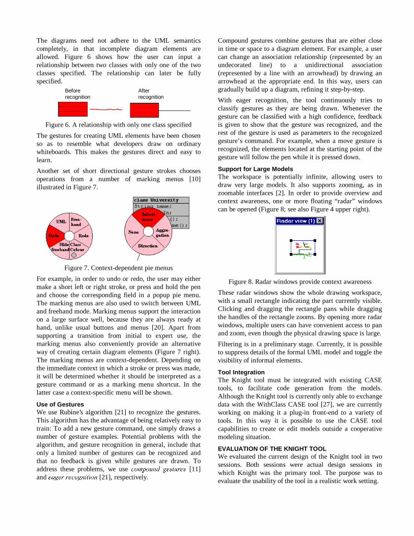
The diagrams need not adhere to the UML semanticscompletely, in that incomplete diagram elements areallowed. Figure 6 shows how the user can input arelationship between two classes with only one of the twoclasses specified. The relationship can later be fullyspecified.
Figure 6. A relationship with only one class specified
The gestures for creating UML elements have been chosenso as to resemble what developers draw on ordinarywhiteboards. This makes the gestures direct and easy tolearn.
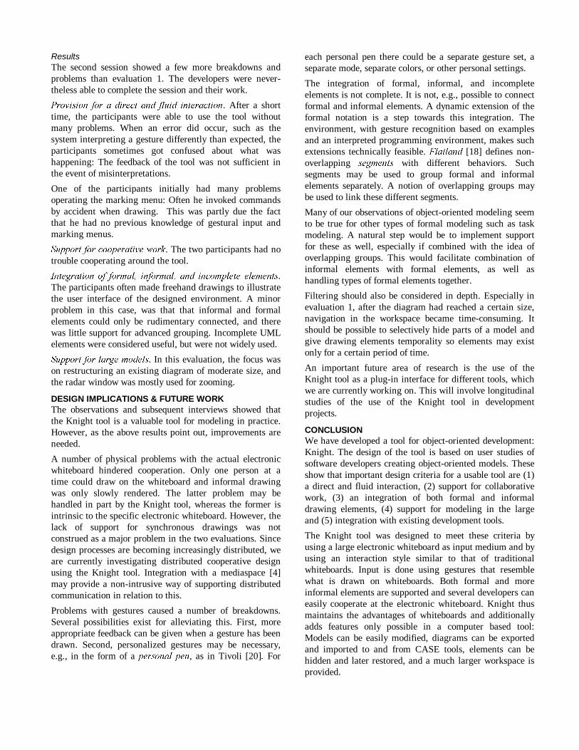
Another set of short directional gesture strokes choosesoperations from a number of marking menus [10]illustrated in Figure 7.
Figure 7. Context-dependent pie menus
For example, in order to undo or redo, the user may eithermake a short left or right stroke, or press and hold the penand choose the corresponding field in a popup pie menu.The marking menus are also used to switch between UMLand freehand mode. Marking menus support the interactionon a large surface well, because they are always ready athand, unlike usual buttons and menus [20]. Apart fromsupporting a transition from initial to expert use, themarking menus also conveniently provide an alternativeway of creating certain diagram elements (Figure 7 right).The marking menus are context-dependent. Depending onthe immediate context in which a stroke or press was made,it will be determined whether it should be interpreted as agesture command or as a marking menu shortcut. In thelatter case a context-specific menu will be shown.
Use of GesturesWe use Rubine’s algorithm [21] to recognize the gestures.This algorithm has the advantage of being relatively easy totrain: To add a new gesture command, one simply draws anumber of gesture examples. Potential problems with thealgorithm, and gesture recognition in general, include thatonly a limited number of gestures can be recognized andthat no feedback is given while gestures are drawn. Toaddress these problems, we use FRPSRXQG� JHVWXUHV [11]and HDJHU�UHFRJQLWLRQ�[21], respectively.
Compound gestures combine gestures that are either closein time or space to a diagram element. For example, a usercan change an association relationship (represented by anundecorated line) to a unidirectional association(represented by a line with an arrowhead) by drawing anarrowhead at the appropriate end. In this way, users cangradually build up a diagram, refining it step-by-step.
With eager recognition, the tool continuously tries toclassify gestures as they are being drawn. Whenever thegesture can be classified with a high confidence, feedbackis given to show that the gesture was recognized, and therest of the gesture is used as parameters to the recognizedgesture’s command. For example, when a move gesture isrecognized, the elements located at the starting point of thegesture will follow the pen while it is pressed down.
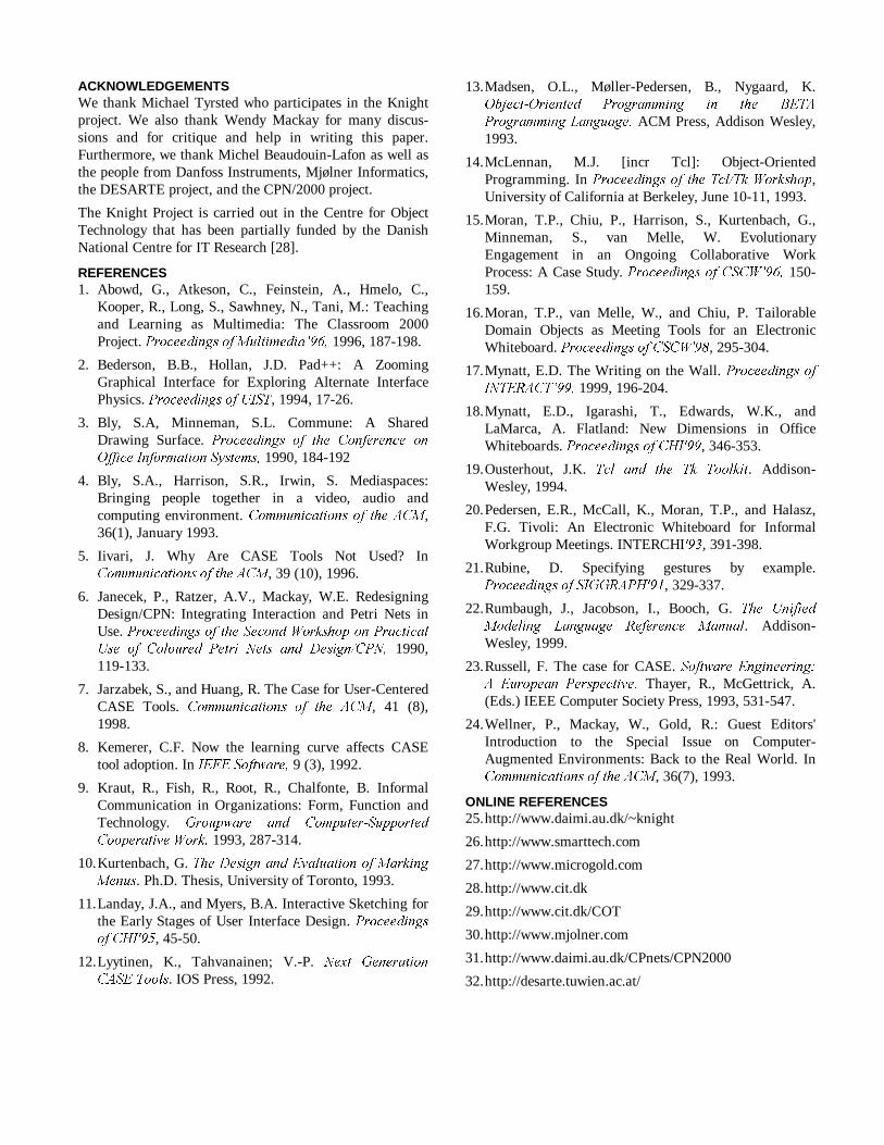
Support for Large ModelsThe workspace is potentially infinite, allowing users todraw very large models. It also supports zooming, as inzoomable interfaces [2]. In order to provide overview andcontext awareness, one or more floating “radar” windowscan be opened (Figure 8; see also Figure 4 upper right).
Figure 8. Radar windows provide context awareness
These radar windows show the whole drawing workspace,with a small rectangle indicating the part currently visible.Clicking and dragging the rectangle pans while draggingthe handles of the rectangle zooms. By opening more radarwindows, multiple users can have convenient access to panand zoom, even though the physical drawing space is large.
Filtering is in a preliminary stage. Currently, it is possibleto suppress details of the formal UML model and toggle thevisibility of informal elements.
Tool IntegrationThe Knight tool must be integrated with existing CASEtools, to facilitate code generation from the models.Although the Knight tool is currently only able to exchangedata with the WithClass CASE tool [27], we are currentlyworking on making it a plug-in front-end to a variety oftools. In this way it is possible to use the CASE toolcapabilities to create or edit models outside a cooperativemodeling situation.
EVALUATION OF THE KNIGHT TOOLWe evaluated the current design of the Knight tool in twosessions. Both sessions were actual design sessions inwhich Knight was the primary tool. The purpose was toevaluate the usability of the tool in a realistic work setting.
Beforerecognition
Afterrecognition

First, a facilitator introduced the Knight tool to theparticipating designers and taught them the basic use of thetool. During the evaluation, he also helped if the designershad problems and asked for help.
We videotaped the sessions and took notes. As in our userstudies, we focused on three aspects of design: cooperation,action, and use. Following the design sessions, weconducted qualitative interviews.
Both sessions were encouraging. Each lasted approximatelyone and a half hours, and the participants were able tomaintain focus on their job, rather than on the tool or theevaluation.
Next we discuss the results of the evaluations with respectto the design criteria identified and summarized in “DesignImplications” above.
Evaluation 1: Designing a New System Using Knight5HVHDUFK� VHWWLQJ� The CPN2000 project [6][31] isconcerned with developing and experimenting with newinteraction techniques for a Petri Net editor with a complexgraphical user interface. The original user interface is atraditional window-icon-menu-pointer interface, whereasthe new interface will use interaction styles such as tool-glasses, marking menus, and gestures. As part of thedesign, three object-oriented models for the handling ofevents and for the implementation of certain interfaceelements had been constructed. We observed the meeting inwhich these three models were integrated into one modelusing the Knight tool.
3DUWLFLSDQWV� Three designers participated in the meeting.One of these had modeled the event handling and wasknowledgeable of UML and traditional CASE tools. Theother two modeled the interaction styles and had littleknowledge of UML.
ResultsThe resulting diagram is shown in Figure 9. This ratherlarge model was constructed with few problems andmishaps.
3URYLVLRQ�IRU�D�GLUHFW�DQG�IOXLG�LQWHUDFWLRQ. After the shortintroduction, the participants were able to use the tool forlong periods without help: the tool had a low threshold forinitial use.
The use of gestures was mostly unproblematic. However,some participants had trouble drawing certain gestures.This may be due in part to too little training, but thegesture set can also be improved. For example, people drawdifferently with respect to size, orientation, and speed, andthe gesture examples used to train the recognizer mustencompass such variations.
6XSSRUW� IRU� FRRSHUDWLYH� ZRUN. The electronic whiteboardworked well as a center of cooperation. The only problemparticipants reported was that only one person could draw
Figure 9. Diagram produced in the first session(with a blow-up of the upper right part)
at a time. Nevertheless, each developer was able to hold hisor her own pen, and they all coordinated their actions whennecessary.
,QWHJUDWLRQ� RI� IRUPDO�� LQIRUPDO� DQG� LQFRPSOHWH� HOHPHQWV.Freehand drawings were widely used and appreciated. Thelow resolution of the actual electronic whiteboard meantthat the freehand drawings were relatively coarse-grained.In addition, response from the electronic whiteboards wasdelayed when a user drew quickly. This meant thatfreehand text was hard to do both legibly and quickly.
6XSSRUW� IRU� ODUJH�PRGHOV. As the size of the model grew,the radar window was used to pan and zoom efficiently.However, the fact that the radar window was the only wayto move around the workspace was problematic. In order tomove a class from one corner of the large diagram toanother, one participant had to move, pan, and then moveagain. This suggests the need for some other means ofscrolling.
Evaluation 2: Restructuring a System Using Knight5HVHDUFK�VHWWLQJ� The DESARTE project [32] is concernedwith designing an electronic support environment forarchitects. As part of this environment, a 3D replacementof the workstation desktop is implemented. A conceptualmodel had previously been designed and was to berestructured during this meeting using the Knight tool.
3DUWLFLSDQWV� Two designers attended the meeting: Thedesigner responsible for implementing the 3D desktop anda user involvement expert with an understanding ofarchitectural work practice. Both had a good knowledge ofobject-oriented modeling.
ResultsThe second session showed a few more breakdowns andproblems than evaluation 1. The developers were never-theless able to complete the session and their work.
3URYLVLRQ� IRU�D�GLUHFW�DQG� IOXLG� LQWHUDFWLRQ. After a shorttime, the participants were able to use the tool withoutmany problems. When an error did occur, such as thesystem interpreting a gesture differently than expected, theparticipants sometimes got confused about what washappening: The feedback of the tool was not sufficient inthe event of misinterpretations.
One of the participants initially had many problemsoperating the marking menu: Often he invoked commandsby accident when drawing. This was partly due the factthat he had no previous knowledge of gestural input andmarking menus.
6XSSRUW�IRU�FRRSHUDWLYH�ZRUN. The two participants had notrouble cooperating around the tool.
,QWHJUDWLRQ�RI� IRUPDO�� LQIRUPDO�� DQG� LQFRPSOHWH� HOHPHQWV.The participants often made freehand drawings to illustratethe user interface of the designed environment. A minorproblem in this case, was that that informal and formalelements could only be rudimentary connected, and therewas little support for advanced grouping. Incomplete UMLelements were considered useful, but were not widely used.
6XSSRUW�IRU�ODUJH�PRGHOV. In this evaluation, the focus wason restructuring an existing diagram of moderate size, andthe radar window was mostly used for zooming.
DESIGN IMPLICATIONS & FUTURE WORKThe observations and subsequent interviews showed thatthe Knight tool is a valuable tool for modeling in practice.However, as the above results point out, improvements areneeded.
A number of physical problems with the actual electronicwhiteboard hindered cooperation. Only one person at atime could draw on the whiteboard and informal drawingwas only slowly rendered. The latter problem may behandled in part by the Knight tool, whereas the former isintrinsic to the specific electronic whiteboard. However, thelack of support for synchronous drawings was notconstrued as a major problem in the two evaluations. Sincedesign processes are becoming increasingly distributed, weare currently investigating distributed cooperative designusing the Knight tool. Integration with a mediaspace [4]may provide a non-intrusive way of supporting distributedcommunication in relation to this.
Problems with gestures caused a number of breakdowns.Several possibilities exist for alleviating this. First, moreappropriate feedback can be given when a gesture has beendrawn. Second, personalized gestures may be necessary,e.g., in the form of a SHUVRQDO�SHQ, as in Tivoli [20]��For
each personal pen there could be a separate gesture set, aseparate mode, separate colors, or other personal settings.
The integration of formal, informal, and incompleteelements is not complete. It is not, e.g., possible to connectformal and informal elements. A dynamic extension of theformal notation is a step towards this integration. Theenvironment, with gesture recognition based on examplesand an interpreted programming environment, makes suchextensions technically feasible. )ODWODQG [18] defines non-overlapping VHJPHQWV with different behaviors. Suchsegments may be used to group formal and informalelements separately. A notion of overlapping groups maybe used to link these different segments.
Many of our observations of object-oriented modeling seemto be true for other types of formal modeling such as taskmodeling. A natural step would be to implement supportfor these as well, especially if combined with the idea ofoverlapping groups. This would facilitate combination ofinformal elements with formal elements, as well ashandling types of formal elements together.
Filtering should also be considered in depth. Especially inevaluation 1, after the diagram had reached a certain size,navigation in the workspace became time-consuming. Itshould be possible to selectively hide parts of a model andgive drawing elements temporality so elements may existonly for a certain period of time.
An important future area of research is the use of theKnight tool as a plug-in interface for different tools, whichwe are currently working on. This will involve longitudinalstudies of the use of the Knight tool in developmentprojects.
CONCLUSIONWe have developed a tool for object-oriented development:Knight. The design of the tool is based on user studies ofsoftware developers creating object-oriented models. Theseshow that important design criteria for a usable tool are (1)a direct and fluid interaction, (2) support for collaborativework, (3) an integration of both formal and informaldrawing elements, (4) support for modeling in the largeand (5) integration with existing development tools.
The Knight tool was designed to meet these criteria byusing a large electronic whiteboard as input medium and byusing an interaction style similar to that of traditionalwhiteboards. Input is done using gestures that resemblewhat is drawn on whiteboards. Both formal and moreinformal elements are supported and several developers caneasily cooperate at the electronic whiteboard. Knight thusmaintains the advantages of whiteboards and additionallyadds features only possible in a computer based tool:Models can be easily modified, diagrams can be exportedand imported to and from CASE tools, elements can behidden and later restored, and a much larger workspace isprovided.
ACKNOWLEDGEMENTSWe thank Michael Tyrsted who participates in the Knightproject. We also thank Wendy Mackay for many discus-sions and for critique and help in writing this paper.Furthermore, we thank Michel Beaudouin-Lafon as well asthe people from Danfoss Instruments, Mjølner Informatics,the DESARTE project, and the CPN/2000 project.
The Knight Project is carried out in the Centre for ObjectTechnology that has been partially funded by the DanishNational Centre for IT Research [28].
REFERENCES1. Abowd, G., Atkeson, C., Feinstein, A., Hmelo, C.,
Kooper, R., Long, S., Sawhney, N., Tani, M.: Teachingand Learning as Multimedia: The Classroom 2000Project. 3URFHHGLQJV�RI�0XOWLPHGLD¶����1996, 187-198.
2. Bederson, B.B., Hollan, J.D. Pad++: A ZoomingGraphical Interface for Exploring Alternate InterfacePhysics. 3URFHHGLQJV�RI�8,67, 1994, 17-26.
3. Bly, S.A, Minneman, S.L. Commune: A SharedDrawing Surface.� 3URFHHGLQJV� RI� WKH� &RQIHUHQFH� RQ2IILFH�,QIRUPDWLRQ�6\VWHPV��1990, 184-192
4. Bly, S.A., Harrison, S.R., Irwin, S. Mediaspaces:Bringing people together in a video, audio andcomputing environment. &RPPXQLFDWLRQV�RI� WKH�$&0,36(1), January 1993.
5. Iivari, J. Why Are CASE Tools Not Used? In&RPPXQLFDWLRQV�RI�WKH�$&0, 39 (10), 1996.
6. Janecek, P., Ratzer, A.V., Mackay, W.E. RedesigningDesign/CPN: Integrating Interaction and Petri Nets inUse. 3URFHHGLQJV�RI�WKH�6HFRQG�:RUNVKRS�RQ�3UDFWLFDO8VH� RI� &RORXUHG� 3HWUL� 1HWV� DQG� 'HVLJQ�&31�� 1990,119-133.
7. Jarzabek, S., and Huang, R. The Case for User-CenteredCASE Tools. &RPPXQLFDWLRQV� RI� WKH� $&0, 41 (8),1998.
8. Kemerer, C.F. Now the learning curve affects CASEtool adoption. In ,(((�6RIWZDUH� 9 (3), 1992.
9. Kraut, R., Fish, R., Root, R., Chalfonte, B. InformalCommunication in Organizations: Form, Function andTechnology. *URXSZDUH� DQG� &RPSXWHU�6XSSRUWHG&RRSHUDWLYH�:RUN��1993, 287-314.
10. Kurtenbach, G. 7KH�'HVLJQ�DQG�(YDOXDWLRQ�RI�0DUNLQJ0HQXV. Ph.D. Thesis, University of Toronto, 1993.
11. Landay, J.A., and Myers, B.A. Interactive Sketching forthe Early Stages of User Interface Design. 3URFHHGLQJVRI�&+,��, 45-50.
12. Lyytinen, K., Tahvanainen; V.-P. 1H[W� *HQHUDWLRQ&$6(�7RROV. IOS Press, 1992.
13. Madsen, O.L., Møller-Pedersen, B., Nygaard, K.2EMHFW�2ULHQWHG� 3URJUDPPLQJ� LQ� WKH� %(7$3URJUDPPLQJ�/DQJXDJH� ACM Press, Addison Wesley,1993.
14. McLennan, M.J. [incr Tcl]: Object-OrientedProgramming. In 3URFHHGLQJV�RI� WKH�7FO�7N�:RUNVKRS,University of California at Berkeley, June 10-11, 1993.
15. Moran, T.P., Chiu, P., Harrison, S., Kurtenbach, G.,Minneman, S., van Melle, W. EvolutionaryEngagement in an Ongoing Collaborative WorkProcess: A Case Study. 3URFHHGLQJV�RI�&6&:¶����150-159.
16. Moran, T.P., van Melle, W., and Chiu, P. TailorableDomain Objects as Meeting Tools for an ElectronicWhiteboard. 3URFHHGLQJV�RI�&6&:��, 295-304.
17. Mynatt, E.D. The Writing on the Wall. 3URFHHGLQJV�RI,17(5$&7¶����1999, 196-204.
18. Mynatt, E.D., Igarashi, T., Edwards, W.K., andLaMarca, A. Flatland: New Dimensions in OfficeWhiteboards. 3URFHHGLQJV�RI�&+,��, 346-353.
19. Ousterhout, J.K. 7FO� DQG� WKH� 7N� 7RRONLW. Addison-Wesley, 1994.
20. Pedersen, E.R., McCall, K., Moran, T.P., and Halasz,F.G. Tivoli: An Electronic Whiteboard for InformalWorkgroup Meetings. INTERCHI��, 391-398.
21. Rubine, D. Specifying gestures by example.3URFHHGLQJV�RI�6,**5$3+��, 329-337.
22. Rumbaugh, J., Jacobson, I., Booch, G. 7KH� 8QLILHG0RGHOLQJ� /DQJXDJH� 5HIHUHQFH� 0DQXDO. Addison-Wesley, 1999.
23. Russell, F. The case for CASE. 6RIWZDUH�(QJLQHHULQJ�$� (XURSHDQ� 3HUVSHFWLYH�� Thayer, R., McGettrick, A.(Eds.) IEEE Computer Society Press, 1993, 531-547.
24. Wellner, P., Mackay, W., Gold, R.: Guest Editors'Introduction to the Special Issue on Computer-Augmented Environments: Back to the Real World. In&RPPXQLFDWLRQV�RI�WKH�$&0, 36(7), 1993.
ONLINE REFERENCES25. http://www.daimi.au.dk/~knight
26. http://www.smarttech.com
27. http://www.microgold.com
28. http://www.cit.dk
29. http://www.cit.dk/COT
30. http://www.mjolner.com
31. http://www.daimi.au.dk/CPnets/CPN2000
32. http://desarte.tuwien.ac.at/