Embed Size (px)
Citation preview

_ WALTER XTRA·TEC® INSERT DRILL
Tool Innovations in Drilling
Product Handbook
Boring/drilling

WALTER TIGER·TEC® SILVER – THE NEW POWER IN MACHINING

CONTENTS
MillingBoring/drilling
2 Walter Xtra·tec® Insert Drill
2 The drill 6 Application examples11 The insert
12 Indexable inserts
12 Walter Select 18 Designation key 20 Insert product range 24 Cutting tool material application tables
26 Walter drill
26 Programme overview28 Xtra·tec® Insert Drill B 4212 32 Xtra·tec® Insert Drill B 4213 36 Xtra·tec® Insert Drill B 421440 Xtra·tec® Insert Drill B 421544 Xtra·tec® Insert Drill B 4213.N
46 Technical information
46 Cutting data 54 Drilling with X offset56 Tolerance ranges 57 Recommended values 68 Application possibilities 69 Problem solutions 70 Drilling calculation formulae 72 Material groups

2
Walter Xtra·tec® Insert Drill: Very exact, very efficient, very economical
THE TOOL– Drill with four edged inserts– Ø range from 13,5 –59 mm– Z = 1 effective– Drilling depth: 2 x D, 3 x D, 4 x D and
5 x D– Ideal insert position provides a balance
of forces in the machining process– Optimised flute for better chip removal
and strong body– Hard-nickel plated surface brings
protection from corrosion and wear and provides better chip flow
– Improved handling and better clamp-ing and release torque through use of TorxPlus screw
– Cylindrical collar for easy measure-ment of tool diameter
Xtra·tec® Insert Drill types: B4212, B4213, B4214, B4215
THE APPLICATION– For all steel and cast iron workpieces
and for stainless materials and materials that are difficult to machine
– For drilling, spot drilling on angled or convex surfaces, chain drilling
– Extremely suitable for general me-chanical engineering, automotive and mass production industry and for the aerospace industry
Optimum arrangement of inserts for balance of forces in the machining process
Nickel-plated, helical flutes for optimum
chip removal

Xtra·tec® Insert Drill 3
YOUR ADVANTAGES– Productivity is increased due to
higher cutting parameters– Low hole tolerance due to optimum
balance of forces– Cost reduction: • 4 usable cutting edges • Higher cutting parameters • Saving of additional subsequent
operations– Excellent surface finish quality due
to wiper edge insert at periphery– High process reliability due to
positive locking of the insert
Xtra·tec® Insert Drill types: B4212, B4213, B4214, B4215
4
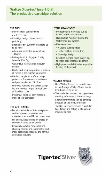
Walter Xtra·tec® Insert Drill:The productive cartridge solution
THE TOOL– Drill with four edged inserts– Z = 1 effective– Cartridge design (1 centre + 1-x
periphery)– Ø range of 59 –120 mm (standard up
to 80 mm) – Adjustable diameter, nominal size
+0.6 mm– Drilling depth 1 x Dc up to 5 x Dc
(standard 3 x Dc)– Walter NCT interface for modular
design– Ideal insert position provides a balance
of forces in the machining process– Hard-nickel plated surface brings
protection from corrosion and wear and provides better chip flow
– Improved handling and better clamp-ing and release torque through use of TorxPlus screw
– Cylindrical collar for easy measure-ment of tool diameter
THE APPLICATION– For all steel and cast iron workpieces
and for stainless materials and materials that are difficult to machine
– For drilling, spot drilling on angled or convex surfaces, chain drilling
– Extremely suitable for general me-chanical engineering, automotive and mass production industry and for the aerospace industry
YOUR ADVANTAGES– Productivity is increased due to
higher cutting parameters– High level of flexibility due to the
Walter modular system– Cost reduction: • 4 usable cutting edges • Higher cutting parameters • Cartridge design– Excellent surface finish quality due
to wiper edge insert at periphery– High process reliability due to positive
locking of the insert
WALTER XPRESS– Here Walter Xpress can provide tools
in the Ø range of 59 –120 mm and in lengths of up to 5 x Dc
– The available standard cartridges (see ordering info) cover this entire range
– Short delivery times can be achieved because of the modular design
– The NCT interface ensures a modular tool design and fitting in almost any machine spindle

Cartridge: FR743C-6 Cartridge: FR746P-6Cartridge: FR744P-6
Xtra·tec® Insert Drill
Tolerance compensation via radially adjustable external cartridge
Easy replacement of wear parts due to cartridge design
Nickel-plated, helical flutes for optimum chip removal
Walter NCT interface for modular design
Xtra·tec® Insert Drill 5

6
Application example 1: Connecting rod machining
ToolDesignation: B4212-5898410Indexable insert: P4840P-3R-E57 / P4841C-3R-E57Grade: WKP25S / WKP35SDiameter: 23,7 mm
WorkpieceDesignation: Connecting rodMaterial: C70Drilling depth: 30 mm
Cutting data:existing Tiger·tec® Silver
vc 210 m/min 210 m/minn 2820 rpm 2820 rpmfz 0,08 mm/rev 0,08 mm/revvf 226 mm/min 226 mm/minZ 1 1Tool life 2500 components 4500 components
Your advantages:– Tool life increase from 2500 pieces to 4500 pieces– Increased tool life and reliability– Better surface finish quality
Comparison between number of components
0 1000 400030002000 5000
previously 2500
Tiger·tec® Silver 4500
Components
+ 80 %Longer tool life

Application example 2:Flex Link machining
Xtra·tec® Insert Drill 7
ToolDesignation: B4214.F40.40.Z1.160R-6Indexable insert: P4848P-6R-E57 / P4841C-6R-E57Grade: WKP35S / WXP40Diameter: 40 mm
WorkpieceDesignation: Flex LinkMaterial: 1,72Drilling depth: 148 mm
Cutting data: existing Tiger·tec® Silver vc 220 m/min 163 m/minn 1751 rpm 1297 rpmfz 0,05 mm/rev 0,15 mm/revvf 88 mm/min 195 mm/minZ 1 1Machining time 101 sec 46 secTool life 2368 components 7104 components
Your advantages:– + 200 % longer tool life – + 120 % higher productivity – spare machine capacity– better process reliability
Comparison between number of components
0 2000 60004000 8000
existing
Tiger·tec® Silver 7104
Components
0 50 150100 200
previously 88
Tiger·tec® Silver 195
vf mm/min
Feed rate
2368+ 200 %
Longer tool life
+ 120 %higher
productivity

8
Application example 3:Connecting rod machining
ToolDesignation: B4212-5642880Indexable insert: P4841P-5R-E57 / P4841C-5R-E57Grade: WKP25S / WKP35SDiameter: 31,5 mm
WorkpieceDesignation: Connecting rodMaterial: 36MnVS4Drilling depth: 20 mm
Cutting data:existing Tiger·tec® Silver
vc 120 m/min 140 m/minn 1200 rpm 1400 rpmfz 0,21 mm/rev 0,18 mm/revvf 250 mm/min 250 mm/minZ 1 1Tool life 800 components 3600 components
Your advantages:– Tool life increase from 800 pieces to 3600 pieces– No vibration– Better surface finish quality– Increased tool life and reliability
Comparison between number of components
10000 30002000 4000
existing
Tiger·tec® Silver 3600
Components
800+ 350 %
Longer tool life

previously 5
Application example 4:Clutch cover machining
Xtra·tec® Insert Drill 9
ToolDesignation: B4212-5538329Indexable insert: P4840P-3R-A57 / P4841C-3R-A57Grade: WKP35S / WXP40Diameter: 22 mm
WorkpieceDesignation: Clutch coverMaterial: GGG-40Drilling depth: 15 mm
Cutting data:existing Tiger·tec® Silver
vc 120 m/min 130 m/minn 1737 rpm 1880 rpmfz 0,1 mm/rev 0,12 mm/revvf 174 mm/min 226 mm/minZ 1 1Machining time 5 sec 4 sec
Your advantages:– + 20 % higher productivity with same tool life– with same tool life– No vibration– Faster cycle times achieved reliably
Machining time
10 2 3 6
Tiger·tec® Silver 4
Seconds
4 5
+ 20 %higher
productivity

10
Walter Xtra·tec® Insert Drill:Very exact, very efficient, very economical
THE OUTER INSERT– Circumference-sintered version with
corner radius at periphery– Circumference fully ground version:
Wiper insert at periphery provides extremely good surface finish quality
– Tiger·tec® Silver: the cutting tool material for maximum cutting speed and maximum process reliability
THE CENTRE INSERT– Tiger·tec® Silver: the cutting tool
material for maximum tool life and maximum process reliability when drilling in ISO P and ISO K materials
– New: new PVD grade WXP40 for longer tool life when drilling in ISO P, ISO M and ISO S materials
– Specially designed for the require-ments of a centre insert

A 57 – The stable one– 0° rake angle – For unfavourable
machining conditions, mainly for cast iron and steel materials
E 57 – The universal one– 13° rake angle– For moderate machin-
ing conditions– For cast iron and
steel, but also for stainless materials and materials that are difficult to cut
Xtra·tec® Insert Drill 11
Cutting edge marking
Cutting edge with a 0° reinforced edge to
prevent chippingSharp dimple geometry
Circumference fully ground
E 67 – The special one– 13° rake angle– Special geometry for
optimum chip forma-tion
– For long-chipping materials such as St37, stainless mate-rials, materials that are difficult to cut and aluminium
THE GEOMETRY VARIANTS

12
STEP 1 Determine the material to be machined from page H 8 onwards in the Walter general catalogue.Note the machin-ing group that corresponds to your material e.g.: P10.
Walter Select for indexable inserts for drilling: Step by step to the right indexable insert
Identifi-cation letters
Machining group Groups of the materials to be machined
P P1–P15 Steel
All types of steel and cast steel, with the exception of steel with an austenitic structure
M M1–M3 Stainless steelStainless austenitic steel and austenitic-ferritic steel and cast steel
K K1–K7 Cast iron
Grey cast iron, cast iron with spheroidal graphite, malle-able cast iron, cast iron with vermicular graphite
N N1–N10 NF metalsAluminium and other non-ferrous metals, non-ferrous materials
S S1–S10High tempera-ture alloys and titanium alloys
Heat resisting special alloys based on iron, nickel and cobalt, titanium and titanium alloys
H H1–H4 Hard materialsHardened steel, hardened cast iron materials, chilled cast iron
O O1–O6 OtherPlastics, fibre glass and carbon fibre reinforced plastics, graphite
STEP 2Select the machining conditions:
Machine stability, clamping system and workpiece
Tool projectionvery good
good moderate
Short projection length a b c
Long projection length b c

Xtra·tec® Insert Drill 13
STEP 3 Select your tool according to your application and individual require-ments. Then select your drill from the corresponding tool page.
Drilling depth Handbook page
2 x Dc ¤28¤
3 x Dc ¤32¤
4 x Dc ¤36¤
5 x Dc ¤40¤
C 12
Drilling
Inserts
P6001 P6003 P6003 P6002 P6004 P6003
P P M K N S
DesignationCutting edges
Dcmm
d1mm
smm
HC HC HC HC HC HC
WXP 45 WMP 35 WMP 35 WXK 25 WNN 25 WMP 35
P6001
P6002
P6003
P6004
P60 . . –D12,00R* 2 12,00 3 3,6 b c b c b bP60 . . –D12,10R 2 12,10 3 3,6 bP60 . . –D12,20R 2 12,20 3 3,6 bP60 . . –D12,30R 2 12,30 3 3,6 bP60 . . –D12,40R 2 12,40 3 3,6 bP60 . . –D12,50R 2 12,50 3 3,6 b c b c b bP60 . . –D12,60R 2 12,60 3 3,6 bP60 . . –D12,70R 2 12,70 3 3,6 b c b c bP60 . . –D12,80R 2 12,80 3 3,6 bP60 . . –D12,90R 2 12,90 3 3,6 bP60 . . –D13,00R 2 13,00 3 3,6 b c b c b bP60 . . –D13,11R 2 13,11 3 3,6 b cP60 . . –D13,20R 2 13,20 3 3,6 b c b bP60 . . –D13,30R 2 13,30 3 3,6 bP60 . . –D13,40R 2 13,40 3 3,6 bP60 . . –D13,50R 2 13,50 3 3,6 b c b c b bP60 . . –D13,60R 2 13,60 3 3,6 bP60 . . –D13,70R 2 13,70 3 3,6 b c b c bP60 . . –D13,80R 2 13,80 3 3,6 bP60 . . –D13,89R 2 13,89 3 3,6 b cP60 . . –D14,00R 2 14,00 3 4,0 b c b c b bP60 . . –D14,10R 2 14,10 3 4,0 bP60 . . –D14,20R 2 14,20 3 4,0 bP60 . . –D14,30R 2 14,30 3 4,0 b c b c bP60 . . –D14,40R 2 14,40 3 4,0 bP60 . . –D14,50R 2 14,50 3 4,0 b c b c b bP60 . . –D14,60R 2 14,60 3 4,0 bP60 . . –D14,68R 2 14,68 3 4,0 b c b c bP60 . . –D14,80R 2 14,80 3 4,0 bP60 . . –D14,90R 2 14,90 3 4,0 bP60 . . –D15,00R 2 15,00 3 4,0 b c b c b bP60 . . –D15,09R 2 15,09 3 4,0 b cP60 . . –D15,20R 2 15,20 3 4,0 bP60 . . –D15,30R 2 15,30 3 4,0 bP60 . . –D15,40R 2 15,40 3 4,0 bP60 . . –D15,47R 2 15,47 3 4,0 b cP60 . . –D15,50R 2 15,50 3 4,0 b c b c b bP60 . . –D15,60R 2 15,60 3 4,0 bP60 . . –D15,70R 2 15,70 3 4,0 b c b bP60 . . –D15,80R 2 15,80 3 4,0 bP60 . . –D15,87R 2 15,87 3 4,0 b c b c b
* Ordering example:P60 . . –D13,00R is available as P6003 in the grade WMP 35 (ISO P, ISO M and ISO S) ‡ P6003–D13,00R WMP 35or as P6001 in the grade WXP 45 (ISO P) ‡ P6001–D13,00R WXP 45
140˚
s
d1
Dc
140˚
s
d1
Dc
P6001P6003P6004
P6002
InsertsP6001, P6002, P6003, P6004
for Xtra·tec® Point Drill
C 146
Technical information – Drilling / boring / reaming
Mat
eria
l gro
up
= Cutting data for wet machining
= Dry machining is possible
Brin
ell h
ardn
ess
HB
Tens
ile s
tren
gth
R mN
/mm
2
Mac
hini
ng g
roup
1
Insert geometry Insert geometry Cutting material grades
Structure of main material groupsand identification letters
Starting values for feedf [mm/rev]
Starting values for feedf [mm/rev]
Starting values for cutting speed vc [m/min]
P6001P6002 P6003 P6004 HC
Dc [mm] Dc [mm] Dc [mm] WXP45 WXK25 WMP35 WNN25
12,0– 15,9
16,0– 21,9
22,0– 31,99
12,0– 15,99
16,0– 21,99
22,0– 31,99
32– 37,99
12,0– 15,9
16,0– 21,9
22,0– 31,99 3 x D 5 x D 7 x D 10 x D 3 x D 5 x D 7 x D 10 x D 3 x D 5 x D 7 x D 10 x D 3 x D 5 x D 7 x D 10 x D
P
Unalloyed steel
C ≤ 0,25% annealed 125 428 P1 C C 0,2 0,25 0,3 0,2 0,25 0,3 0,4 120 100 80 80 120 100 80 60C > 0,25 ... ≤ 0,55 % annealed 190 639 P2 C C 0,2 0,25 0,3 0,2 0,25 0,3 0,4 120 100 80 80 120 100 80 50C > 0,25 ... ≤ 0,55 % tempered 210 708 P3 C C 0,2 0,25 0,3 0,2 0,25 0,3 0,4 110 100 80 80 110 100 80 50C > 0,55 % annealed 190 639 P4 C C 0,2 0,25 0,3 0,2 0,25 0,3 0,4 120 100 80 80 120 100 80 50C > 0,55 % tempered 300 1013 P5 C C 0,15 0,2 0,22 0,15 0,2 0,22 0,25 90 80 60 60 90 80 60 40free cutting steel (short-chipping) annealed 220 745 P6 C C C 0,18 0,22 0,25 0,18 0,22 0,25 0,3 100 90 80 80 100 90 80 50
Low-alloyed steel
annealed 175 591 P7 C C 0,2 0,25 0,3 0,2 0,25 0,3 0,4 120 100 80 80 120 100 80 50tempered 300 1013 P8 C C 0,2 0,25 0,3 0,2 0,25 0,3 0,4 80 70 60 60 80 70 60 30tempered 380 1282 P9 C C 0,18 0,22 0,25 0,18 0,22 0,25 0,3 60 50 40 40 60 50 40 30tempered 430 1477 P10 C C 0,15 0,2 0,22 0,15 0,2 0,22 0,28 60 50 40 40 60 50 40 30
High-alloyed steel and high-alloyed tool steel
annealed 200 675 P11 C C 0,15 0,2 0,22 0,15 0,2 0,22 0,28 70 60 50 50 60 50 40 30hardened and tempered 300 1013 P12 C C 0,12 0,15 0,2 0,12 0,15 0,2 0,25 70 60 50 50 60 50 40 30hardened and tempered 400 1361 P13 C C 0,1 0,12 0,8 0,1 0,12 0,18 0,22 70 60 50 50 60 50 40 30
Stainless steelferritic / martensitic, annealed 200 675 P14 C C 0,15 0,2 0,22 0,15 0,2 0,22 0,25 70 60 50 50 60 50 40 30martensitic, tempered 330 1114 P15 C C 0,12 0,15 0,2 0,12 0,15 0,2 0,22 70 60 50 50 60 50 40 30
M Stainless steelaustenitic, quench hardened 200 675 M1 C C 0,1 0,12 0,15 0,18 70 50 40 30austenitic, precipitation hardened (PH) 300 1013 M2austenitic / ferritic, duplex 230 778 M3 C C 0,08 0,1 0,12 0,15 70 50 40 30
K
Malleable cast ironferritic 200 675 K1 C C C 0,2 0,25 0,3 0,2 0,25 0,3 0,4 120 110 100 100 120 110 100 100 100 90 70 60pearlitic 260 867 K2 C C C 0,2 0,25 0,3 0,2 0,25 0,3 0,4 120 110 100 100 120 110 100 100 100 90 70 60
Grey cast ironlow tensile strength 180 602 K3 C C C 0,2 0,25 0,4 0,2 0,25 0,4 0,5 140 130 120 110 160 150 140 120 140 130 120 90high tensile strength / austenitic 245 825 K4 C C C 0,2 0,25 0,4 0,2 0,25 0,4 0,5 130 120 110 110 150 140 130 110 120 110 100 80
Cast iron with spheroidal graphiteferritic 155 518 K5 C C C 0,2 0,25 0,35 0,2 0,25 0,35 0,4 120 110 100 100 120 110 100 100 110 100 90 70pearlitic 265 885 K6 C C 0,2 0,25 0,35 0,2 0,25 0,35 0,4 120 100 100 100 110 90 90 90 90 80 70 60
GGV (CGI) 200 675 K7 C C C 0,18 0,2 0,25 0,18 0,2 0,25 0,3 110 90 90 90 110 90 90 90 90 80 70 60
N
Aluminium wrought alloyscannot be hardened 30 – N1 C C 0,4 0,5 0,6 320 280hardenable, hardened 100 343 N2 C C 0,4 0,5 0,6 320 280
Cast aluminium alloys≤ 12 % Si, cannot be hardened 75 260 N3 C C 0,25 0,3 0,35 400 400≤ 12 % Si, hardenable, hardened 90 314 N4 C C 0,25 0,3 0,35 320 320 280 260> 12 % Si, cannot be hardened 130 447 N5 C C C 0,25 0,3 0,35 220 220 160 150
Magnesium alloys 70 250 N6 C C 0,12 0,18 0,18 240 200 160 150
Copper and copper alloys(bronze / brass)
unalloyed, electrolytic copper 100 343 N7 C C 0,12 0,18 0,18 120 120 80 80brass, bronze, red brass 90 314 N8 C C 0,16 0,2 0,24 160 120 80 80Cu-alloys, short-chipping 110 382 N9 C C C 0,12 0,18 0,18 120 120 80 80high-strength, Ampco 300 1013 N10
S
Heat-resistant alloys
Fe-basedannealed 200 675 S1 C C 0,08 0,12 0,15 0,18 30 20 20hardened 280 943 S2 C C 0,08 0,12 0,15 0,18 20 20 15
Ni or Co baseannealed 250 839 S3 C C 0,08 0,12 0,15 0,15 20 20 15hardened 350 1177 S4 C C 0,05 0,08 0,1 0,12 15 12 10cast 320 1076 S5 C C 0,08 0,12 0,15 0,18 20 20 15
Titanium alloyspure titanium 200 675 S6α and β alloys, hardened 375 1262 S7 C C 0,12 0,15 0,18 0,18 70 60 50β alloys 410 1396 S8 C C 0,12 0,15 0,18 0,18 60 50 40
Tungsten alloys 300 1013 S9Molybdenum alloys 300 1013 S10
H Hardened steelhardened and tempered 50 HRC – H1hardened and tempered 55 HRC – H2hardened and tempered 60 HRC – H3
Hardened cast iron hardened and tempered 55 HRC – H4
O
Thermoplasts without abrasive fillers O1Thermosetting plastics without abrasive fillers O2Plastic, glass-fibre reinforced GFRP O3Plastic, carbon-fibre reinforced CFRP O4Plastic, aramid fibre reinforced AFRP O5Graphite (technical) 80 Shore O6
1 The machining groups are assigned from ¤H 8¤ onwards. HC = Coated carbide
C C Recommended application (the specified cutting data are regarded as starting values for the recommended application).C Possible application. Limited to 2 x Dc drilling depth. MQL (minimum quantity lubrication) or compressed air is recommended.
Centring with a B4011 / B4013 is recommended when using the B4017.A pilot hole approx. 1 x Dc with a B4011 / B4013 is strictly necessary when using the B4010!
Cutting data for drillingwith Xtra·tec® Point Drill Dc 12–38 mm
STEP 4 Determine your best indexable index grade and -geometry on the relevant tool page. In so doing, please take into consid-eration the ma-chining conditions (step 2) and the material to be machined.
STEP 5 Select the cutting data from page 46 onwards in this handbook.
good moderate unfavourable
machining conditions
Best insert for:

14
Walter Select – DrillingWalter Xtra·tec® Insert Drill and Point Drill
Tool type
Lc approx. 1,3 x Dc 2 x Dc 2,5 x Dc 3 x Dc
Drill(R) = right handed
B 4011 (R) B 3212 (R) B 4212 (R) B 3011.M (R) B 4012C (R) B 4013 (R) B 3213 (R) B 4213 (R) B 4213.N
Xtra·tec® Xtra·tec® Xtra·tec® Xtra·tec® Xtra·tec® Xtra·tec®
Ø range [mm] 12–25 10–18 13,5–59 59,5–120 12–29 12–37 10–18 13,5–59 59,5–120
Walter general catalogue page ¤C 50¤ C 16 Handbook page 28 C 58 C 60 C 62 C 70 Handbook
page 32Handbook page 44
P Steel C C C C C C C C C C C C C C C C C C
M Stainless steel C C C C C C C C C C C C C C C C
K Cast iron C C C C C C C C C C C C C C C C C C
N NF metals C C C C C C C C C C C C
S Difficult-to-cut materials C C C C C C C C C C C C C C C C
H Hard materials
O Other
Basic insert shape
Insert types P 600 . . LCMX . . P 484 . . P 284 . .P 600 . .
TC . . P 600 . . LCMX . . P 484 . . P 484 . .
Drilling depth [mm] ≤ 1,3 x Dc≤ 2 x Dc ≤ 2 x Dc ≤ 2 x Dc ≤ 2,5 x Dc ≤ 3 x Dc ≤ 3 x Dc ≤ 3 x Dc ≤ 3 x Dc

Xtra·tec® Insert Drill 15
Tool type
Lc approx. 1,3 x Dc 2 x Dc 2,5 x Dc 3 x Dc
Drill(R) = right handed
B 4011 (R) B 3212 (R) B 4212 (R) B 3011.M (R) B 4012C (R) B 4013 (R) B 3213 (R) B 4213 (R) B 4213.N
Xtra·tec® Xtra·tec® Xtra·tec® Xtra·tec® Xtra·tec® Xtra·tec®
Ø range [mm] 12–25 10–18 13,5–59 59,5–120 12–29 12–37 10–18 13,5–59 59,5–120
Walter general catalogue page ¤C 50¤ C 16 Handbook page 28 C 58 C 60 C 62 C 70 Handbook
page 32Handbook page 44
P Steel C C C C C C C C C C C C C C C C C C
M Stainless steel C C C C C C C C C C C C C C C C
K Cast iron C C C C C C C C C C C C C C C C C C
N NF metals C C C C C C C C C C C C
S Difficult-to-cut materials C C C C C C C C C C C C C C C C
H Hard materials
O Other
Basic insert shape
Insert types P 600 . . LCMX . . P 484 . . P 284 . .P 600 . .
TC . . P 600 . . LCMX . . P 484 . . P 484 . .
Drilling depth [mm] ≤ 1,3 x Dc≤ 2 x Dc ≤ 2 x Dc ≤ 2 x Dc ≤ 2,5 x Dc ≤ 3 x Dc ≤ 3 x Dc ≤ 3 x Dc ≤ 3 x Dc
C C
Primary application
C
Other application

16
Tool type
Lc approx. 4 x Dc 5 x Dc 7 x Dc 10 x Dc
Drill(R) = right handed
B 3214 (R) B 4214 (R) B 4015 (R) B 4215 (R) B 4017 (R) B 4010 (R)
Xtra·tec® Xtra·tec® Xtra·tec® Xtra·tec®
Ø range [mm] 10–18 16–59 12–37 16–59 12–31 18–24
Walter general catalogue page ¤C 78¤ Handbook page 36 ¤C 80¤ Handbook
page 40 ¤C 86¤ ¤C 88¤
P Steel C C C C C C C C C C
M Stainless steel C C C C C C
K Cast iron C C C C C C C C C C C C
N NF metals C C C C C C C
S Difficult-to-cut materials C C C
H Hard materials
O Other
Basic insert shape
Insert types LCMX . . P 484 . . P 600 . . P 484 . . P 600 . . P 600 . .
Drilling depth [mm] ≤ 4 x Dc ≤ 4 x Dc ≤ 5 x Dc ≤ 5 x Dc ≤ 7 x Dc ≤ 10 x Dc
Walter Select – DrillingWalter Xtra·tec® Insert Drill and Point Drill

Xtra·tec® Insert Drill 17
C C
Primary application
C
Other application
Tool type
Lc approx. 4 x Dc 5 x Dc 7 x Dc 10 x Dc
Drill(R) = right handed
B 3214 (R) B 4214 (R) B 4015 (R) B 4215 (R) B 4017 (R) B 4010 (R)
Xtra·tec® Xtra·tec® Xtra·tec® Xtra·tec®
Ø range [mm] 10–18 16–59 12–37 16–59 12–31 18–24
Walter general catalogue page ¤C 78¤ Handbook page 36 ¤C 80¤ Handbook
page 40 ¤C 86¤ ¤C 88¤
P Steel C C C C C C C C C C
M Stainless steel C C C C C C
K Cast iron C C C C C C C C C C C C
N NF metals C C C C C C C
S Difficult-to-cut materials C C C
H Hard materials
O Other
Basic insert shape
Insert types LCMX . . P 484 . . P 600 . . P 484 . . P 600 . . P 600 . .
Drilling depth [mm] ≤ 4 x Dc ≤ 4 x Dc ≤ 5 x Dc ≤ 5 x Dc ≤ 7 x Dc ≤ 10 x Dc

18
Designation key for indexable inserts P 484 .
P 484 0 P – 2 R – A57 WKP 35S1 2 3 4 5 6 7
1
Walter indexable insert designation
3
C Centre insert
P Outer insert
2
0 ground
1 sintered
4
Insert size
5
R Right handed
6
Walter geometry
A 57The stable one
E 57The universal one
E 67The sharp one
7
Walter cutting material grade

Xtra·tec® Insert Drill 19
Designation key for Xtra·tec® Insert Drill
B 421 2. F25 24. Z1. 048 R – 31 2 3 4 5 6 7 8
1
Walter indexable insert designation
4
Nominal diameter [mm]
7
R rightversion
3
Shank variant and diameter, e.g.:
F 25metric, Ø 25
UF 31inches, Ø 1 ¼"
N 8NCT 80
2
2 2 x Dc
3 3 x Dc
4 4 x Dc
5 5 x Dc
5
Effective number of teeth
6
Drilling depth [mm]
8
Insert size

20
Square P 484 . Tiger·tec®
l
α
s
r
l
α
sє є
Indexable inserts
Num
ber
of
cutt
ing
edge
s P M K SHC HC HC HC HC
Designationl
mms
mmr
mm α є WK
P25
S
WK
P35
S
WS
P45
WS
P45
WA
K15
WK
P25
S
WK
P35
S
WS
P45
WX
P40
Outer insert
P4840P-1R-A57 4 4,55 1,96 0,29 11° 90° b c c c b c c
P4840P-2R-A57 4 5,52 2,38 0,34 11° 90° b c c c b c c
P4840P-3R-A57 4 6,5 2,8 0,4 11° 90° b c c c b c c
P4840P-4R-A57 4 7,8 3,36 0,48 11° 90° b c c c b c c
P4840P-5R-A57 4 9,56 4,12 0,59 11° 90° b c c c b c c
P4840P-6R-A57 4 11,75 4,87 0,7 11° 90° b c c c b c c
P4840P-7R-A57 4 14,03 5,53 0,8 11° 90° b c c c b c c
P4840P-8R-A57 4 16,5 5,53 1,0 11° 90° b c c c b c c
Outer insert
P4840P-1R-E57 4 4,55 1,96 0,29 11° 90° a b c c b c c
P4840P-2R-E57 4 5,52 2,38 0,34 11° 90° a b c c b c c
P4840P-3R-E57 4 6,5 2,8 0,4 11° 90° a b c c b c c
P4840P-4R-E57 4 7,8 3,36 0,48 11° 90° a b c c b c c
P4840P-5R-E57 4 9,56 4,12 0,59 11° 90° a b c c b c c
P4840P-6R-E57 4 11,75 4,87 0,7 11° 90° a b c c b c c
P4840P-7R-E57 4 14,03 5,53 0,8 11° 90° a b c c b c c
P4840P-8R-E57 4 16,5 5,53 1,0 11° 90° a b c c b c c
HC = Coated carbide

Indexable inserts
Num
ber
of
cutt
ing
edge
s P M K SHC HC HC HC HC
Designationl
mms
mmr
mm α є WK
P25
S
WK
P35
S
WS
P45
WS
P45
WA
K15
WK
P25
S
WK
P35
S
WS
P45
WX
P40
Outer insert
P4840P-1R-E67 4 4,55 1,96 0,29 11° 90° b c c b c
P4840P-2R-E67 4 5,52 2,38 0,34 11° 90° b c c b c
P4840P-3R-E67 4 6,5 2,8 0,4 11° 90° b c c b c
P4840P-4R-E67 4 7,8 3,36 0,48 11° 90° b c c b c
P4840P-5R-E67 4 9,56 4,12 0,59 11° 90° b c c b c
P4840P-6R-E67 4 11,75 4,87 0,7 11° 90° b c c b c
P4840P-7R-E67 4 14,03 5,53 0,8 11° 90° b c c b c
P4840P-8R-E67 4 16,5 5,53 1,0 11° 90° b c c b c
Outer insert
P4841P-1R-A57 4 4,55 1,96 0,29 11° 90° b c c c b c c
P4841P-2R-A57 4 5,52 2,38 0,34 11° 90° b c c c b c c
P4841P-3R-A57 4 6,5 2,8 0,4 11° 90° b c c c b c c
P4841P-4R-A57 4 7,8 3,36 0,48 11° 90° b c c c b c c
P4841P-5R-A57 4 9,56 4,12 0,59 11° 90° b c c c b c c
P4841P-6R-A57 4 11,75 4,87 0,7 11° 90° b c c c b c c
P4841P-7R-A57 4 14,03 5,53 0,8 11° 90° b c c c b c c
P4841P-8R-A57 4 16,5 5,53 1,0 11° 90° b c c c b c c
HC = Coated carbide
Xtra·tec® Insert Drill 21
good moderate unfavourable
machining conditions
Best insert for:

22
Indexable inserts
Num
ber
of
cutt
ing
edge
s P M K SHC HC HC HC HC
Designationl
mms
mmr
mm α є WK
P25
S
WK
P35
S
WS
P45
WS
P45
WA
K15
WK
P25
S
WK
P35
S
WS
P45
WX
P40
Outer insert
P4841P-1R-E57 4 4,55 1,96 0,29 11° 90° a b c c b c c
P4841P-2R-E57 4 5,52 2,38 0,34 11° 90° a b c c b c c
P4841P-3R-E57 4 6,5 2,8 0,4 11° 90° a b c c b c c
P4841P-4R-E57 4 7,8 3,36 0,48 11° 90° a b c c b c c
P4841P-5R-E57 4 9,56 4,12 0,59 11° 90° a b c c b c c
P4841P-6R-E57 4 11,75 4,87 0,7 11° 90° a b c c b c c
P4841P-7R-E57 4 14,03 5,53 0,8 11° 90° a b c c b c c
P4841P-8R-E57 4 16,5 5,53 1,0 11° 90° a b c c b c c
Centre insert
P4841C-1R-A57 4 4,9 1,96 0,29 11° 90° c c c
P4841C-2R-A57 4 5,95 2,38 0,34 11° 90° c c c
P4841C-3R-A57 4 7,0 2,8 0,4 11° 90° c c c
P4841C-4R-A57 4 8,4 3,36 0,48 11° 90° c c c
P4841C-5R-A57 4 10,29 4,12 0,59 11° 90° c c c
P4841C-6R-A57 4 12,24 4,87 0,7 11° 90° c c c
P4841C-7R-A57 4 14,69 5,53 0,8 11° 90° c c c
P4841C-8R-A57 4 17,49 5,53 1,0 11° 90° c c c
HC = Coated carbide
l
α
s
r
l
α
sє є
Square P 484 . Tiger·tec®

Indexable inserts
Num
ber
of
cutt
ing
edge
s P M K SHC HC HC HC HC
Designationl
mms
mmr
mm α є WK
P25
S
WK
P35
S
WS
P45
WS
P45
WA
K15
WK
P25
S
WK
P35
S
WS
P45
WX
P40
Centre insert
P4841C-1R-E57 4 4,9 1,96 0,29 11° 90° c c c
P4841C-2R-E57 4 5,95 2,38 0,34 11° 90° c c c
P4841C-3R-E57 4 7,0 2,8 0,4 11° 90° c c c
P4841C-4R-E57 4 8,4 3,36 0,48 11° 90° c c c
P4841C-5R-E57 4 10,29 4,12 0,59 11° 90° c c c
P4841C-6R-E57 4 12,24 4,87 0,7 11° 90° c c c
P4841C-7R-E57 4 14,69 5,53 0,8 11° 90° c c c
P4841C-8R-E57 4 17,49 5,53 1,0 11° 90° c c c
Centre insert
P4840C-1R-E67 4 4,9 1,96 0,29 11° 90° c c c
P4840C-2R-E67 4 5,95 2,38 0,34 11° 90° c c c
P4840C-3R-E67 4 7,0 2,8 0,4 11° 90° c c c
P4840C-4R-E67 4 8,4 3,36 0,48 11° 90° c c c
P4840C-5R-E67 4 10,29 4,12 0,59 11° 90° c c c
P4840C-6R-E67 4 12,24 4,87 0,7 11° 90° c c c
P4840C-7R-E67 4 14,69 5,53 0,8 11° 90° c c c
P4840C-8R-E67 4 17,49 5,53 1,0 11° 90° c c c
HC = Coated carbide
Xtra·tec® Insert Drill 23
good moderate unfavourable
machining conditions
Best insert for:

HC = Coated carbide
Primary application Other application
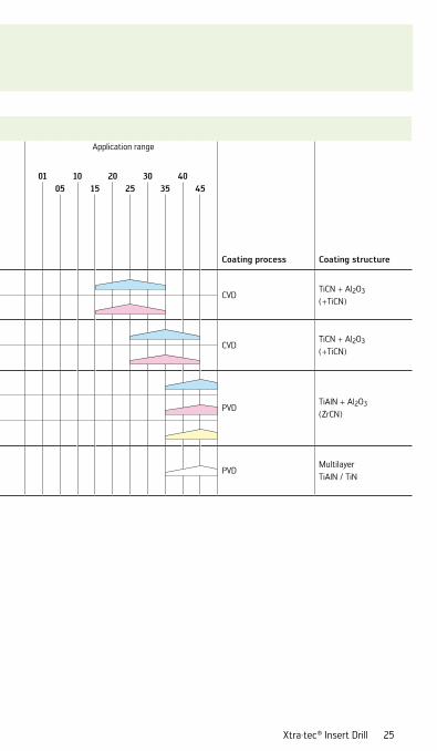
Grades for drilling
WalterGrade designation Standard designation
Workpiece material group Application range
Coating process Coating structure
P M K N S H 01 10 20 30 40
Ste
el
Sta
inle
ss s
teel
Cast
iron
NF
met
als
Dif
ficu
lt-t
o-cu
t m
ater
ials
Har
d m
ater
ials
05 15 25 35 45
WKP25SHC – P25 ••
CVDTiCN + Al2O3
(+TiCN)HC – K25 ••
WKP35SHC – P35 ••
CVDTiCN + Al2O3
(+TiCN)HC – K35 ••
WSP45
HC – P45 ••PVD
TiAlN + Al2O3
(ZrCN)HC – M45 ••HC – S45 ••
WXP40 HC – P45 •• •• •• •• PVDMultilayer TiAlN / TiN
24
Cutting tool material application tables
Grades for drilling
WalterGrade designation Standard designation
Workpiece material group Application range
Coating process Coating structure
P M K N S H 01 10 20 30 40
Ste
el
Sta
inle
ss s
teel
Cast
iron
NF
met
als
Dif
ficu
lt-t
o-cu
t m
ater
ials
Har
d m
ater
ials
05 15 25 35 45
WKP25SHC – P25 ••
CVDTiCN + Al2O3
(+TiCN)HC – K25 ••
WKP35SHC – P35 ••
CVDTiCN + Al2O3
(+TiCN)HC – K35 ••
WSP45
HC – P45 ••PVD
TiAlN + Al2O3
(ZrCN)HC – M45 ••HC – S45 ••
WXP40 HC – P45 •• •• •• •• PVDMultilayer TiAlN / TiN
Xtra·tec® Insert Drill 25

26
Drilling
Walter Select see GC page C 46¤ Walter Select see GC page C 46¤Walter Select
see GC page C 46¤
Lc = 1,3 x Dc Lc = 2 x Dc Lc = 3 x Dc Lc = 4 x Dc Lc = 5 x Dc Lc = 7 x Dc Lc = 10 x Dc Lc = 2 x Dc
Dc = 12–25 mm Dc = 12–38 mm Dc = 12–38 mm Dc = 12–32 mm Dc = 18–25 mm Dc = 12–29 mm
B 4011GC page C 50
B 4013GC page C 62
B 4015GC page C 80
B 4017GC page C 86
B 4010GC page C 88
B 4012CGC page C 60
Xtra·tec® Xtra·tec® Xtra·tec® Xtra·tec® Xtra·tec® Xtra·tec®
Dc = 13,5–59 mm Dc = 13,5–59 mm Dc = 59–120 mm Dc = 17–59 mm Dc = 17–59 mm
B 4212HB page 28
B 4213HB page 32
B 4213.NHB page 44
B 4214HB page 36
B 4215HB page 40
Xtra·tec® Xtra·tec® Xtra·tec® Xtra·tec® Xtra·tec®
Dc = 10–18 mm Dc = 59,8–120 mm Dc = 10–18 mm Dc = 16–58 mm Dc = 16–58 mm
B 3212GC page C 16
B 3011MGC page C 58
B 3213GC page C 70
B 3213GC page C 70
B 3214GC page C 78
Walter drill: Product range overview of drilling and boring tools with indexable inserts

Drilling
Walter Select see GC page C 46¤ Walter Select see GC page C 46¤Walter Select
see GC page C 46¤
Lc = 1,3 x Dc Lc = 2 x Dc Lc = 3 x Dc Lc = 4 x Dc Lc = 5 x Dc Lc = 7 x Dc Lc = 10 x Dc Lc = 2 x Dc
Dc = 12–25 mm Dc = 12–38 mm Dc = 12–38 mm Dc = 12–32 mm Dc = 18–25 mm Dc = 12–29 mm
B 4011GC page C 50
B 4013GC page C 62
B 4015GC page C 80
B 4017GC page C 86
B 4010GC page C 88
B 4012CGC page C 60
Xtra·tec® Xtra·tec® Xtra·tec® Xtra·tec® Xtra·tec® Xtra·tec®
Dc = 13,5–59 mm Dc = 13,5–59 mm Dc = 59–120 mm Dc = 17–59 mm Dc = 17–59 mm
B 4212HB page 28
B 4213HB page 32
B 4213.NHB page 44
B 4214HB page 36
B 4215HB page 40
Xtra·tec® Xtra·tec® Xtra·tec® Xtra·tec® Xtra·tec®
Dc = 10–18 mm Dc = 59,8–120 mm Dc = 10–18 mm Dc = 16–58 mm Dc = 16–58 mm
B 3212GC page C 16
B 3011MGC page C 58
B 3213GC page C 70
B 3213GC page C 70
B 3214GC page C 78
HB: This page information relates to this handbook.GC: This page information relates to the Walter general catalogue 2012.
Xtra·tec® Insert Drill 27

Dc d1 d4
l4 l5Lc
28
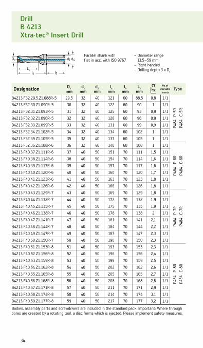
DrillB 4212Xtra·tec® Insert Drill
– Diameter range 13,5 –59 mm– Right handed– Drilling depth 2 x Dc
Designation Dcmm
d1mm
d4mm
l4mm
l5mm
Lcmm
No. of indexable
insertsType
B4212.F20.13,5.Z1.027R-1 13,5 20 30 47 50 27 0,17 1/1
P484
. P-
1RP4
84 .
C-1R
B4212.F20.14.Z1.028R-1 14 20 30 48 50 28 0,17 1/1
B4212.F20.14,5.Z1.029R-1 14,5 20 30 49 50 29 0,17 1/1
B4212.F20.15.Z1.030R-1 15 20 30 50 50 30 0,17 1/1
B4212.F20.15,5.Z1.031R-1 15,5 20 30 51 50 31 0,18 1/1
B4212.F25.16.Z1.032R-1 16 25 32 57 56 32 0,32 1/1
B4212.F25.16,5.Z1.033R-2 16,5 25 32 58 56 33 0,3 1/1
P484
. P-
2RP4
84 .
C-2R
B4212.F25.17.Z1.034R-2 17 25 32 59 56 34 0,42 1/1
B4212.F25.17,5.Z1.035R-2 17,5 25 32 60 56 35 0,4 1/1
B4212.F25.18.Z1.036R-2 18 25 32 61 56 36 0,33 1/1
B4212.F25.18,5.Z1.037R-2 18,5 25 32 62 56 37 0,45 1/1
B4212.F25.19.Z1.038R-2 19 25 32 63 56 38 0,34 1/1
B4212.F25.19,5.Z1.039R-2 19,5 25 32 64 56 39 0,35 1/1
B4212.F25.20.Z1.040R-2 20 25 32 65 56 40 0,45 1/1
B4212.F25.20,5.Z1.041R-3 20,5 25 32 66 56 41 0,44 1/1
P484
. P-
3RP4
84 .
C-3R
B4212.F25.21.Z1.042R-3 21 25 32 67 56 42 0,45 1/1
B4212.F25.21,5.Z1.043R-3 21,5 25 32 68 56 43 0,37 1/1
B4212.F25.22.Z1.044R-3 22 25 32 69 56 44 0,37 1/1
B4212.F25.22,5.Z1.045R-3 22,5 25 32 70 56 45 0,46 1/1
B4212.F25.23.Z1.046R-3 23 25 32 71 56 46 0,48 1/1
B4212.F25.23,5.Z1.047R-3 23,5 25 32 72 56 47 0,44 1/1
B4212.F25.24.Z1.048R-3 24 25 32 73 56 48 0,48 1/1
B4212.F25.24,5.Z1.049R-4 24,5 25 32 74 56 49 0,5 1/1
P484
. P-
4R
P484
. C-
4R
B4212.F25.25.Z1.050R-4 25 25 32 75 56 50 0,4 1/1
B4212.F32.25,5.Z1.051R-4 25,5 32 40 83 60 51 0,8 1/1
B4212.F32.26.Z1.052R-4 26 32 40 84 60 52 0,8 1/1
B4212.F32.26,5.Z1.053R-4 26,5 32 40 85 60 53 0,8 1/1
B4212.F32.27.Z1.054R-4 27 32 40 86 60 54 0,7 1/1
B4212.F32.27,5.Z1.055R-4 27,5 32 40 87 60 55 0,8 1/1
B4212.F32.28.Z1.056R-4 28 32 40 88 60 56 0,8 1/1
B4212.F32.28,5.Z1.057R-4 28,5 32 40 89 60 57 0,8 1/1
B4212.F32.29.Z1.058R-4 29 32 40 90 60 58 0,9 1/1
Bodies, assembly parts and screwdrivers are included in the standard pack. Important: Where through bores are created by a rotating tool, a disc forms which is ejected. Please implement safety measures.
Parallel shank with flat in acc. with ISO 9766

Xtra·tec® Insert Drill 29
Accessories Dc mm 13,5-20 20,5-24 24,5-29
Torque screwdriver FS2001 FS2001 FS2003
Interchangeable blade
FS2011 (Torx 7 IP)
FS2012 (Torx 8 IP)
FS2013 (Torx 9 IP)
Assembly parts Dc mm 13,5-16 16,5-20 20,5-24 24,5-29
Clamping screw for insert Tightening torque
FS2120 (Torx 6 IP)
0,4 Nm
FS2111 (Torx 7 IP)
0,9 Nm
FS1454 (Torx 8 IP)
1,2 Nm
FS1457 (Torx 9 IP)
2,0 Nm
Indexable inserts
P M K N S HHC HC HC HC HC HC
Designation Size WK
P25
SW
KP3
5 S
WS
P45
WM
P35
WX
P45
WS
P45
WM
P35
WK
P25
SW
KP3
5 S
WX
K25
WN
N25
WS
P45
WM
P35
WX
P40
Outer insert
P4840P– . R–A57 1–4 a b c b b c b
P4840P– . R–E57 1–4 a b c b b c b
P4840P– . R–E67 1–4 a b c b b
P4841P– . R–A57 1–4 a b c b b c b
P4841P– . R–E57 1–4 a b c b b c b
Centre insert
P4841C– . R–A57 1–4 c c c
P4841C– . R–E57 1–4 c c c
P4840C– . R–E67 1–4 c c c
HC = Coated carbide
good moderate unfavourable
machining conditions
Best insert for:

Dc d1 d4
l4 l5Lc
30
DrillB 4212Xtra·tec® Insert Drill
– Diameter range 13,5 –59 mm– Right handed– Drilling depth 2 x Dc
Designation Dcmm
d1mm
d4mm
l4mm
l5mm
Lcmm
No. of indexable
insertsType
B4212.F32.29,5.Z1.059R-5 29,5 32 40 91 60 59 0,7 1/1
P484
. P-
5R
P484
. C-
5R
B4212.F32.30.Z1.060R-5 30 32 40 92 60 60 0,7 1/1
B4212.F32.31.Z1.062R-5 31 32 40 94 60 62 0,8 1/1
B4212.F32.32.Z1.064R-5 32 32 40 96 60 64 0,8 1/1
B4212.F32.33.Z1.066R-5 33 32 40 98 60 66 0,8 1/1
B4212.F32.34.Z1.068R-5 34 32 40 100 60 68 0,8 1/1
B4212.F32.35.Z1.070R-5 35 32 40 102 60 70 0,9 1/1
B4212.F32.36.Z1.072R-6 36 32 40 104 60 72 0,8 1/1
P484
. P-
6R
P484
. C-
6R
B4212.F40.37.Z1.074R-6 37 40 50 114 70 74 1,4 1/1
B4212.F40.38.Z1.076R-6 38 40 50 116 70 76 1,4 1/1
B4212.F40.39.Z1.078R-6 39 40 50 118 70 78 1,4 1/1
B4212.F40.40.Z1.080R-6 40 40 50 120 70 80 1,5 1/1
B4212.F40.41.Z1.082R-6 41 40 50 122 70 82 1,5 1/1
B4212.F40.42.Z1.084R-6 42 40 50 124 70 84 1,6 1/1
B4212.F40.43.Z1.086R-7 43 40 50 126 70 86 1,5 1/1
P484
. P-
7R
P484
. C-
7R
B4212.F40.44.Z1.088R-7 44 40 50 128 70 88 1,6 1/1
B4212.F40.45.Z1.090R-7 45 40 50 130 70 90 1,6 1/1
B4212.F40.46.Z1.092R-7 46 40 50 132 70 92 1,7 1/1
B4212.F40.47.Z1.094R-7 47 40 50 134 70 94 1,7 1/1
B4212.F40.48.Z1.096R-7 48 40 50 136 70 96 1,8 1/1
B4212.F40.49.Z1.098R-7 49 40 50 138 70 98 1,8 1/1
B4212.F40.50.Z1.100R-7 50 40 50 140 70 100 1,9 1/1
B4212.F40.51.Z1.102R-8 51 40 50 142 70 102 1,9 1/1
P484
. P-
8R
P484
. C-
8R
B4212.F40.52.Z1.104R-8 52 40 50 144 70 104 2 1/1
B4212.F40.53.Z1.106R-8 53 40 50 146 70 106 2 1/1
B4212.F40.54.Z1.108R-8 54 40 50 148 70 108 2,1 1/1
B4212.F40.55.Z1.110R-8 55 40 50 150 70 110 2,2 1/1
B4212.F40.56.Z1.112R-8 56 40 50 152 70 112 2,2 1/1
B4212.F40.57.Z1.114R-8 57 40 50 154 70 114 2,3 1/1
B4212.F40.58.Z1.116R-8 58 40 50 156 70 116 2,4 1/1
B4212.F40.59.Z1.118R-8 59 40 50 158 70 118 2,5 1/1
Bodies, assembly parts and screwdrivers are included in the standard pack. Important: Where through bores are created by a rotating tool, a disc forms which is ejected. Please implement safety measures.
Parallel shank with flat in acc. with ISO 9766

Xtra·tec® Insert Drill 31
Accessories Dc mm 29,5-42 43-59
Torque screwdriver FS2003 FS2003
Interchangeable blade FS2014 (Torx 15 IP) FS2015 (Torx 20 IP)
Assembly parts Dc mm 29,5-35 36-42 43-59
Clamping screw for insert Tightening torque
FS2080 (Torx 15 IP)
2,5 Nm
FS1453 (Torx 15 IP)
3,5 Nm
FS1495 (Torx 20 IP)
5,0 Nm
Indexable inserts
P M K N S HHC HC HC HC HC HC
Designation Size WK
P25
SW
KP3
5 S
WS
P45
WM
P35
WX
P45
WS
P45
WM
P35
WK
P25
SW
KP3
5 S
WX
K25
WN
N25
WS
P45
WM
P35
WX
P40
Outer insert
P4840P– . R–A57 5–8 a b c b b c b
P4840P– . R–E57 5–8 a b c b b c b
P4840P– . R–E67 5–8 a b c b b c b
P4841P– . R–A57 5–8 a b c b b c b
P4841P– . R–E57 5–8 a b c b b c b
Centre insert
P4841C– . R–A57 5–8 c c c
P4841C– . R–E57 5–8 c c c
P4840C– . R–E67 5–8 c c c
HC = Coated carbide
good moderate unfavourable
machining conditions
Best insert for:

Dc d1 d4
l4 l5Lc
32
DrillB 4213Xtra·tec® Insert Drill
– Diameter range 13,5 –59 mm– Right handed– Drilling depth 3 x Dc
Designation Dcmm
d1mm
d4mm
l4mm
l5mm
Lcmm
No. of indexable
insertsType
B4213.F20.13,5.Z1.040R-1 13,5 20 30 61 50 40,5 0,17 1/1
P484
. P-
1RP4
84 .
C-1R
B4213.F20.14.Z1.042R-1 14 20 30 62 50 42 0,18 1/1
B4213.F20.14,5.Z1.043R-1 14,5 20 30 64 50 43,5 0,18 1/1
B4213.F20.15.Z1.045R-1 15 20 30 65 50 45 0,18 1/1
B4213.F20.15,5.Z1.046R-1 15,5 20 30 67 50 46,5 0,19 1/1
B4213.F25.16.Z1.048R-1 16 25 32 73 56 48 0,33 1/1
B4213.F25.16,5.Z1.049R-2 16,5 25 32 75 56 49,5 0,44 1/1
P484
. P-
2RP4
84 .
C-2R
B4213.F25.17.Z1.051R-2 17 25 32 76 56 51 0,43 1/1
B4213.F25.17,5.Z1.052R-2 17,5 25 32 77,5 56 52,5 0,44 1/1
B4213.F25.18.Z1.054R-2 18 25 32 79 56 54 0,43 1/1
B4213.F25.18,5.Z1.055R-2 18,5 25 32 80,5 56 55,5 0,46 1/1
B4213.F25.19.Z1.057R-2 19 25 32 82 56 57 0,46 1/1
B4213.F25.19,5.Z1.058R-2 19,5 25 32 84 56 58,5 0,47 1/1
B4213.F25.20.Z1.060R-2 20 25 32 85 56 60 0,48 1/1
B4213.F25.20,5.Z1.061R-3 20,5 25 32 87 56 61,5 0,5 1/1
P484
. P-
3RP4
84 .
C-3R
B4213.F25.21.Z1.063R-3 21 25 32 88 56 63 0,4 1/1
B4213.F25.21,5.Z1.064R-3 21,5 25 32 90 56 64,5 0,5 1/1
B4213.F25.22.Z1.066R-3 22 25 32 91 56 66 0,42 1/1
B4213.F25.22,5.Z1.067R-3 22,5 25 32 93 56 67,5 0,5 1/1
B4213.F25.23.Z1.069R-3 23 25 32 94 56 69 0,43 1/1
B4213.F25.23,5.Z1.070R-3 23,5 25 32 96 56 70,5 0,5 1/1
B4213.F25.24.Z1.072R-3 24 25 32 97 56 72 0,44 1/1
B4213.F25.24,5.Z1.073R-4 24,5 25 32 99 56 73,5 0,5 1/1
P484
. P-
4R
P484
. C-
4R
B4213.F25.25.Z1.075R-4 25 25 32 100 56 75 0,6 1/1
B4213.F32.25,5.Z1.076R-4 25,5 32 40 109 60 76,5 0,8 1/1
B4213.F32.26.Z1.078R-4 26 32 40 110 60 78 0,8 1/1
B4213.F32.26,5.Z1.079R-4 26,5 32 40 112 60 79,5 0,9 1/1
B4213.F32.27.Z1.081R-4 27 32 40 113 60 81 0,9 1/1
B4213.F32.27,5.Z1.082R-4 27,5 32 40 115 60 82,5 0,9 1/1
B4213.F32.28.Z1.084R-4 28 32 40 116 60 84 0,8 1/1
B4213.F32.28,5.Z1.085R-4 28,5 32 40 118 60 85,5 0,9 1/1
B4213.F32.29.Z1.087R-4 29 32 40 119 60 87 0,9 1/1
Bodies, assembly parts and screwdrivers are included in the standard pack. Important: Where through bores are created by a rotating tool, a disc forms which is ejected. Please implement safety measures.
Parallel shank with flat in acc. with ISO 9767

Xtra·tec® Insert Drill 33
Accessories Dc mm 13,5-20 20,5-24 24,5-29
Torque screwdriver FS2001 FS2001 FS2003
Interchangeable blade
FS2011 (Torx 7 IP)
FS2012 (Torx 8 IP)
FS2013 (Torx 9 IP)
Assembly parts Dc mm 13,5-16 16,5-20 20,5-24 24,5-29
Clamping screw for insert Tightening torque
FS2120 (Torx 6 IP)
0,4 Nm
FS2111 (Torx 7 IP)
0,9 Nm
FS1454 (Torx 8 IP)
1,2 Nm
FS1457 (Torx 9 IP)
2,0 Nm
Indexable inserts
P M K N S HHC HC HC HC HC HC
Designation Size WK
P25
SW
KP3
5 S
WS
P45
WM
P35
WX
P45
WS
P45
WM
P35
WK
P25
SW
KP3
5 S
WX
K25
WN
N25
WS
P45
WM
P35
WX
P40
Outer insert
P4840P– . R–A57 1–4 a b c b b c b
P4840P– . R–E57 1–4 a b c b b c b
P4840P– . R–E67 1–4 a b c b b c b
P4841P– . R–A57 1–4 a b c b b c b
P4841P– . R–E57 1–4 a b c b b c b
Centre insert
P4841C– . R–A57 1–4 c c c
P4841C– . R–E57 1–4 c c c
P4840C– . R–E67 1–4 c c c
HC = Coated carbide
good moderate unfavourable
machining conditions
Best insert for:
Dc d1 d4
l4 l5Lc
34
– Diameter range 13,5 –59 mm
– Right handed– Drilling depth 3 x Dc
Parallel shank with flat in acc. with ISO 9767
DrillB 4213Xtra·tec® Insert Drill
Designation Dcmm
d1mm
d4mm
l4mm
l5mm
Lcmm
No. of indexable
insertsType
B4213.F32.29,5.Z1.088R-5 29,5 32 40 121 60 88,5 0,8 1/1
P484
. P-
5R
P484
. C-
5R
B4213.F32.30.Z1.090R-5 30 32 40 122 60 90 1 1/1
B4213.F32.31.Z1.093R-5 31 32 40 125 60 93 0,9 1/1
B4213.F32.32.Z1.096R-5 32 32 40 128 60 96 0,9 1/1
B4213.F32.33.Z1.099R-5 33 32 40 131 60 99 0,9 1/1
B4213.F32.34.Z1.102R-5 34 32 40 134 60 102 1 1/1
B4213.F32.35.Z1.105R-5 35 32 40 137 60 105 1 1/1
B4213.F32.36.Z1.108R-6 36 32 40 140 60 108 1 1/1
P484
. P-
6R
P484
. C-
6R
B4213.F40.37.Z1.111R-6 37 40 50 151 70 111 1,5 1/1
B4213.F40.38.Z1.114R-6 38 40 50 154 70 114 1,6 1/1
B4213.F40.39.Z1.117R-6 39 40 50 157 70 117 1,6 1/1
B4213.F40.40.Z1.120R-6 40 40 50 160 70 120 1,7 1/1
B4213.F40.41.Z1.123R-6 41 40 50 163 70 123 1,8 1/1
B4213.F40.42.Z1.126R-6 42 40 50 166 70 126 1,8 1/1
B4213.F40.43.Z1.129R-7 43 40 50 169 70 129 1,8 1/1
P484
. P-
7R
P484
. C-
7R
B4213.F40.44.Z1.132R-7 44 40 50 172 70 132 1,9 1/1
B4213.F40.45.Z1.135R-7 45 40 50 175 70 135 1,9 1/1
B4213.F40.46.Z1.138R-7 46 40 50 178 70 138 2 1/1
B4213.F40.47.Z1.141R-7 47 40 50 181 70 141 2,1 1/1
B4213.F40.48.Z1.144R-7 48 40 50 184 70 144 2,2 1/1
B4213.F40.49.Z1.147R-7 49 40 50 187 70 147 2,3 1/1
B4213.F40.50.Z1.150R-7 50 40 50 190 70 150 2,3 1/1
B4213.F40.51.Z1.153R-8 51 40 50 193 70 153 2,3 1/1
P484
. P-
8R
P484
. C-
8R
B4213.F40.52.Z1.156R-8 52 40 50 196 70 156 2,4 1/1
B4213.F40.53.Z1.159R-8 53 40 50 199 70 159 2,5 1/1
B4213.F40.54.Z1.162R-8 54 40 50 202 70 162 2,6 1/1
B4213.F40.55.Z1.165R-8 55 40 50 205 70 165 2,7 1/1
B4213.F40.56.Z1.168R-8 56 40 50 208 70 168 2,8 1/1
B4213.F40.57.Z1.171R-8 57 40 50 211 70 171 2,9 1/1
B4213.F40.58.Z1.174R-8 58 40 50 214 70 174 3,1 1/1
B4213.F40.59.Z1.177R-8 59 40 50 217 70 177 3,2 1/1
Bodies, assembly parts and screwdrivers are included in the standard pack. Important: Where through bores are created by a rotating tool, a disc forms which is ejected. Please implement safety measures.

Xtra·tec® Insert Drill 35
good moderate unfavourable
machining conditions
Best insert for:
Accessories Dc mm 29,5-42 43-59
Torque screwdriver FS2003 FS2003
Interchangeable blade FS2014 (Torx 15 IP) FS2015 (Torx 20 IP)
Assembly parts Dc mm 29,5-35 36-42 43-59
Clamping screw for insert Tightening torque
FS2080 (Torx 15 IP)
2,5 Nm
FS1453 (Torx 15 IP)
3,5 Nm
FS1495 (Torx 20 IP)
5,0 Nm
Indexable inserts
P M K N S HHC HC HC HC HC HC
Designation Size WK
P25
SW
KP3
5 S
WS
P45
WM
P35
WX
P45
WS
P45
WM
P35
WK
P25
SW
KP3
5 S
WX
K25
WN
N25
WS
P45
WM
P35
WX
P40
Outer insert
P4840P– . R–A57 5–8 a b c b b c b
P4840P– . R–E57 5–8 a b c b b c b
P4840P– . R–E67 5–8 a b c b b c b
P4841P– . R–A57 5–8 a b c b b c b
P4841P– . R–E57 5–8 a b c b b c b
Centre insert
P4841C– . R–A57 5–8 c c c
P4841C– . R–E57 5–8 c c c
P4840C– . R–E67 5–8 c c c
HC = Coated carbide

Dc d1 d4
l4 l5Lc
36
DrillB 4214Xtra·tec® Insert Drill
– Diameter range 17–59 mm
– Right handed– Drilling depth 4 x Dc
Parallel shank with flat in acc. with ISO 9768
Designation Dcmm
d1mm
d4mm
l4mm
l5mm
Lcmm
No. of indexable
insertsType
B4214.F25.17.Z1.068R-2 17 25 32 93 56 68 0,36 1/1
P484
. P-
2RP4
84 .
C-2R
B4214.F25.18.Z1.072R-2 18 25 32 97 56 72 0,38 1/1
B4214.F25.19.Z1.076R-2 19 25 32 101 56 76 0,39 1/1
B4214.F25.20.Z1.080R-2 20 25 32 105 56 80 0,4 1/1
B4214.F25.21.Z1.084R-3 21 25 32 109 56 84 0,5 1/1
P484
. P-
3RP4
84 .
C-3R
B4214.F25.22.Z1.088R-3 22 25 32 113 56 88 0,5 1/1
B4214.F25.23.Z1.092R-3 23 25 32 117 56 92 0,6 1/1
B4214.F25.24.Z1.096R-3 24 25 32 121 56 96 0,5 1/1
B4214.F25.25.Z1.100R-4 25 25 32 125 56 100 0,5 1/1
P484
. P-
4RP4
84 .
C-4RB4214.F32.26.Z1.104R-4 26 32 40 136 60 104 0,8 1/1
B4214.F32.27.Z1.108R-4 27 32 40 140 60 108 0,8 1/1
B4214.F32.28.Z1.112R-4 28 32 40 144 60 112 0,9 1/1
B4214.F32.29.Z1.116R-4 29 32 40 148 60 116 0,9 1/1
Bodies, assembly parts and screwdrivers are included in the standard pack. Important: Where through bores are created by a rotating tool, a disc forms which is ejected. Please implement safety measures.

Xtra·tec® Insert Drill 37
Accessories Dc mm 17-20 21-24 25-29
Torque screwdriver FS2001 FS2001 FS2003
Interchangeable blade
FS2011 (Torx 7 IP)
FS2012 (Torx 8 IP)
FS2013 (Torx 9 IP)
Indexable inserts
P M K N S HHC HC HC HC HC HC
Designation Size WK
P25
SW
KP3
5 S
WS
P45
WM
P35
WX
P45
WS
P45
WM
P35
WK
P25
SW
KP3
5 S
WX
K25
WN
N25
WS
P45
WM
P35
WX
P40
Outer insert
P4840P– . R–A57 1–4 a b c b b c b
P4840P– . R–E57 1–4 a b c b b c b
P4840P– . R–E67 1–4 a b c b b c b
P4841P– . R–A57 1–4 a b c b b c b
P4841P– . R–E57 1–4 a b c b b c b
Centre insert
P4841C– . R–A57 1–4 c c c
P4841C– . R–E57 1–4 c c c
P4840C– . R–E67 1–4 c c c
HC = Coated carbide
good moderate unfavourable
machining conditions
Best insert for:
Assembly parts Dc mm 17-20 21-24 25-29
Clamping screw for insert Tightening torque
FS2111 (Torx 7 IP)
0,9 Nm
FS1454 (Torx 8 IP)
1,2 Nm
FS1457 (Torx 9 IP)
2,0 Nm

Dc d1 d4
l4 l5Lc
38
DrillB 4214Xtra·tec® Insert Drill
– Diameter range 17–59 mm
– Right handed– Drilling depth 4 x Dc
Parallel shank with flat in acc. with ISO 9768
Designation Dcmm
d1mm
d4mm
l4mm
l5mm
Lcmm
No. of indexable
insertsType
B4214.F32.30.Z1.120R-5 30 32 40 152 60 120 0,9 1/1
P484
. P-
5R
P484
. C-
5R
B4214.F32.31.Z1.124R-5 31 32 40 156 60 124 1 1/1
B4214.F32.32.Z1.128R-5 32 32 40 160 60 128 1 1/1
B4214.F32.33.Z1.132R-5 33 32 40 164 60 132 1,1 1/1
B4214.F32.34.Z1.136R-5 34 32 40 168 60 136 1,1 1/1
B4214.F32.35.Z1.140R-5 35 32 40 172 60 140 1,2 1/1
B4214.F32.36.Z1.144R-6 36 32 40 176 60 144 1,1 1/1
P484
. P-
6R
P484
. C-
6R
B4214.F40.37.Z1.148R-6 37 40 50 188 70 148 1,7 1/1
B4214.F40.38.Z1.152R-6 38 40 50 192 70 152 1,8 1/1
B4214.F40.39.Z1.156R-6 39 40 50 196 70 156 1,8 1/1
B4214.F40.40.Z1.160R-6 40 40 50 200 70 160 1,9 1/1
B4214.F40.41.Z1.164R-6 41 40 50 204 70 164 2 1/1
B4214.F40.42.Z1.168R-6 42 40 50 208 70 168 2,1 1/1
B4214.F40.43.Z1.172R-7 43 40 50 212 70 172 2 1/1
P484
. P-
7R
P484
. C-
7R
B4214.F40.44.Z1.176R-7 44 40 50 216 70 176 2,1 1/1
B4214.F40.45.Z1.180R-7 45 40 50 220 70 180 2,2 1/1
B4214.F40.46.Z1.184R-7 46 40 50 224 70 184 2,3 1/1
B4214.F40.47.Z1.188R-7 47 40 50 228 70 188 2,4 1/1
B4214.F40.48.Z1.192R-7 48 40 50 232 70 192 2,5 1/1
B4214.F40.49.Z1.196R-7 49 40 50 236 70 196 2,7 1/1
B4214.F40.50.Z1.200R-7 50 40 50 240 70 200 2,8 1/1
B4214.F40.51.Z1.204R-8 51 40 50 244 70 204 2,8 1/1
P484
. P-
8R
P484
. C-
8R
B4214.F40.52.Z1.208R-8 52 40 50 248 70 208 2,9 1/1
B4214.F40.53.Z1.212R-8 53 40 50 252 70 212 3 1/1
B4214.F40.54.Z1.216R-8 54 40 50 256 70 216 3,2 1/1
B4214.F40.55.Z1.220R-8 55 40 50 260 70 220 3,3 1/1
B4214.F40.56.Z1.224R-8 56 40 50 264 70 224 3,4 1/1
B4214.F40.57.Z1.228R-8 57 40 50 268 70 228 3,6 1/1
B4214.F40.58.Z1.232R-8 58 40 50 272 70 232 3,8 1/1
B4214.F40.59.Z1.236R-8 59 40 50 276 70 236 3,9 1/1
Bodies, assembly parts and screwdrivers are included in the standard pack. Important: Where through bores are created by a rotating tool, a disc forms which is ejected. Please implement safety measures.

Xtra·tec® Insert Drill 39
good moderate unfavourable
machining conditions
Best insert for:
Accessories Dc mm 30-42 43-59
Torque screwdriver FS2003 FS2003
Interchangeable blade FS2014 (Torx 15 IP) FS2015 (Torx 20 IP)
Assembly parts Dc mm 30-35 36-42 43-59
Clamping screw for insert Tightening torque
FS2080 (Torx 15 IP)
2,5 Nm
FS1453 (Torx 15 IP)
3,5 Nm
FS1495 (Torx 20 IP)
5,0 Nm
Indexable inserts
P M K N S HHC HC HC HC HC HC
Designation Size WK
P25
SW
KP3
5 S
WS
P45
WM
P35
WX
P45
WS
P45
WM
P35
WK
P25
SW
KP3
5 S
WX
K25
WN
N25
WS
P45
WM
P35
WX
P40
Outer insert
P4840P– . R–A57 5–8 a b c b b c b
P4840P– . R–E57 5–8 a b c b b c b
P4840P– . R–E67 5–8 a b c b b c b
P4841P– . R–A57 5–8 a b c b b c b
P4841P– . R–E57 5–8 a b c b b c b
Centre insert
P4841C– . R–A57 5–8 c c c
P4841C– . R–E57 5–8 c c c
P4840C– . R–E67 5–8 c c c
HC = Coated carbide
Dc d4 d1
l4 l5
Lc
40
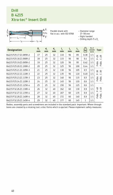
Drill B 4215 Xtra·tec® Insert Drill
– Diameter range 17–59 mm
– Right handed– Drilling depth 5 x Dc
Designation Dcmm
d1mm
d4mm
l4mm
l5mm
Lcmm
No. of indexable
insertsType
B4215.F25.17.Z1.085R-2 17 25 32 110 56 85 0,38 1/1
P484
. P-
2RP4
84 .
C-2R
B4215.F25.18.Z1.090R-2 18 25 32 115 56 90 0,4 1/1
B4215.F25.19.Z1.095R-2 19 25 32 120 56 95 0,42 1/1
B4215.F25.20.Z1.100R-2 20 25 32 125 56 100 0,44 1/1
B4215.F25.21.Z1.105R-3 21 25 32 130 56 105 0,5 1/1
P484
. P-
3RP4
84 .
C-3R
B4215.F25.22.Z1.110R-3 22 25 32 135 56 110 0,49 1/1
B4215.F25.23.Z1.115R-3 23 25 32 140 56 115 0,5 1/1
B4215.F25.24.Z1.120R-3 24 25 32 145 56 120 0,6 1/1
B4215.F25.25.Z1.125R-4 25 25 32 150 56 125 0,6 1/1
P484
. P-
4RP4
84 .
C-4RB4215.F32.26.Z1.130R-4 26 32 40 162 60 130 0,9 1/1
B4215.F32.27.Z1.135R-4 27 32 40 167 60 135 0,9 1/1
B4215.F32.28.Z1.140R-4 28 32 40 172 60 140 0,9 1/1
B4215.F32.29.Z1.145R-4 29 32 40 177 60 145 1 1/1
Bodies, assembly parts and screwdrivers are included in the standard pack. Important: Where through bores are created by a rotating tool, a disc forms which is ejected. Please implement safety measures.
Parallel shank with flat in acc. with ISO 9768

Xtra·tec® Insert Drill 41
Accessories Dc mm 17-20 21-24 25-29
Torque screwdriver FS2001 FS2001 FS2003
Interchangeable blade
FS2011 (Torx 7 IP)
FS2012 (Torx 8 IP)
FS2013 (Torx 9 IP)
Indexable inserts
P M K N S HHC HC HC HC HC HC
Designation Size WK
P25
SW
KP3
5 S
WS
P45
WM
P35
WX
P45
WS
P45
WM
P35
WK
P25
SW
KP3
5 S
WX
K25
WN
N25
WS
P45
WM
P35
WX
P40
Outer insert
P4840P– . R–A57 2–4 a b c b b c b
P4840P– . R–E57 2–4 a b c b b c b
P4840P– . R–E67 2–4 a b c b b c b
P4841P– . R–A57 2–4 a b c b b c b
P4841P– . R–E57 2–4 a b c b b c b
Centre insert
P4841C– . R–A57 2–4 c c c
P4841C– . R–E57 2–4 c c c
P4840C– . R–E67 2–4 c c c
HC = Coated carbide
good moderate unfavourable
machining conditions
Best insert for:
Assembly parts Dc mm 17-20 21-24 25-29
Clamping screw for insert Tightening torque
FS2111 (Torx 7 IP)
0,9 Nm
FS1454 (Torx 8 IP)
1,2 Nm
FS1457 (Torx 9 IP)
2,0 Nm

Dc d4 d1
l4 l5
Lc
42
DrillB 4215Xtra·tec® Insert Drill
– Diameter range 17–59 mm
– Right handed– Drilling depth 5 x Dc
Parallel shank with flat in acc. with ISO 9768
Designation Dcmm
d1mm
d4mm
l4mm
l5mm
Lcmm
No. of indexable
insertsType
B4215.F32.30.Z1.150R-5 30 32 40 182 60 150 1 1/1
P484
. P-
5R
P484
. C-
5R
B4215.F32.31.Z1.155R-5 31 32 40 187 60 155 1,1 1/1
B4215.F32.32.Z1.160R-5 32 32 40 192 60 160 1,1 1/1
B4215.F32.33.Z1.165R-5 33 32 40 197 60 165 1,2 1/1
B4215.F32.34.Z1.170R-5 34 32 40 202 60 170 1,3 1/1
B4215.F32.35.Z1.175R-5 35 32 40 207 60 175 1,3 1/1
B4215.F32.36.Z1.180R-6 36 32 40 212 60 180 1,3 1/1
P484
. P-
6R
P484
. C-
6R
B4215.F40.37.Z1.185R-6 37 40 50 225 70 185 1,9 1/1
B4215.F40.38.Z1.190R-6 38 40 50 230 70 190 1,9 1/1
B4215.F40.39.Z1.195R-6 39 40 50 235 70 195 2 1/1
B4215.F40.40.Z1.200R-6 40 40 50 240 70 200 2,1 1/1
B4215.F40.41.Z1.205R-6 41 40 50 245 70 205 2,2 1/1
B4215.F40.42.Z1.210R-6 42 40 50 250 70 210 2,3 1/1
B4215.F40.43.Z1.215R-7 43 40 50 255 70 215 2,3 1/1
P484
. P-
7R
P484
. C-
7R
B4215.F40.44.Z1.220R-7 44 40 50 260 70 220 2,4 1/1
B4215.F40.45.Z1.225R-7 45 40 50 265 70 225 2,6 1/1
B4215.F40.46.Z1.230R-7 46 40 50 270 70 230 2,7 1/1
B4215.F40.47.Z1.235R-7 47 40 50 275 70 235 2,8 1/1
B4215.F40.48.Z1.240R-7 48 40 50 280 70 240 2,9 1/1
B4215.F40.49.Z1.245R-7 49 40 50 285 70 245 3 1/1
B4215.F40.50.Z1.250R-7 50 40 50 290 70 250 3,2 1/1
B4215.F40.51.Z1.255R-8 51 40 50 295 70 255 3,2 1/1
P484
. P-
8R
P484
. C-
8R
B4215.F40.52.Z1.260R-8 52 40 50 300 70 260 3,4 1/1
B4215.F40.53.Z1.265R-8 53 40 50 305 70 265 3,5 1/1
B4215.F40.54.Z1.270R-8 54 40 50 310 70 270 3,7 1/1
B4215.F40.55.Z1.275R-8 55 40 50 315 70 275 3,8 1/1
B4215.F40.56.Z1.280R-8 56 40 50 320 70 280 4 1/1
B4215.F40.57.Z1.285R-8 57 40 50 325 70 285 4,2 1/1
B4215.F40.58.Z1.290R-8 58 40 50 330 70 290 4,4 1/1
B4215.F40.59.Z1.295R-8 59 40 50 335 70 295 4,6 1/1
Bodies, assembly parts and screwdrivers are included in the standard pack. Important: Where through bores are created by a rotating tool, a disc forms which is ejected. Please implement safety measures.

Xtra·tec® Insert Drill 43
good moderate unfavourable
machining conditions
Best insert for:
Accessories Dc mm 30-42 43-59
Torque screwdriver FS2003 FS2003
Interchangeable blade FS2014 (Torx 15 IP) FS2015 (Torx 20 IP)
Assembly parts Dc mm 30-35 36-42 43-59
Clamping screw for insert Tightening torque
FS2080 (Torx 15 IP)
2,5 Nm
FS1453 (Torx 15 IP)
3,5 Nm
FS1495 (Torx 20 IP)
5,0 Nm
Indexable inserts
P M K N S HHC HC HC HC HC HC
Designation Size WK
P25
SW
KP3
5 S
WS
P45
WM
P35
WX
P45
WS
P45
WM
P35
WK
P25
SW
KP3
5 S
WX
K25
WN
N25
WS
P45
WM
P35
WX
P40
Outer insert
P4840P– . R–A57 5–8 a b c b b c b
P4840P– . R–E57 5–8 a b c b b c b
P4840P– . R–E67 5–8 a b c b b c b
P4841P– . R–A57 5–8 a b c b b c b
P4841P– . R–E57 5–8 a b c b b c b
Centre insert
P4841C– . R–A57 5–8 c c c
P4841C– . R–E57 5–8 c c c
P4840C– . R–E67 5–8 c c c
HC = Coated carbide

44
DrillB 4213.NXtra·tec® Insert Drill
– Diameter range 65–80 mm
– Right handed– Drilling depth 3 x Dc
Modular adaptor
Designation Dcmm
d1mm
l4mm
Lcmm
Number of external
cartridges
Number of internal
cartridges
No. of indexable
insertsType
B4213.N8.065.Z1.195R-5 65 NCT 80 245 195 1xFR738
+FR741 1xFR737C-5 4,1 3/1 P484 . P-5R P484 . C-5R
B4213.N8.068.Z1.204R-6 68 NCT 80 254 204 1xFR744
+FR745 1xFR743C-6 4,5 3/1
P484 . P-6R P484 . C-6RB4213.N8.070.Z1.210R-6 70 NCT
80 260 210 1xFR744+FR746 1xFR743C-P 4,7 3/1
B4213.N8.078.Z1.234R-6 78 NCT 80 284 234 1XFR744
+FR748 1xFR743C-6 6 3/1
B4213.N8.080.Z1.240R-5 80 NCT 80 290 240 1xFR738
+FR739 1xFR737C-5 6,2 1/1 P484 . P-5R P484 . C-5R
Bodies, assembly parts and screwdrivers are included in the standard pack. Important: Where through bores are created by a rotating tool, a disc forms which is ejected. Please implement safety measures.
Lcl4
d1Dc
Lcl4
d1Dc
For other diameters between 59,5 mm and 120 mm, appropriate tool designs and additional cartridges are available. If necessary, please contact your Walter consultant.
DCmm No. of cartridges No. of inserts
FR73
7C–
5
FR73
8P–
5
FR73
9P–
5
FR74
0P–
5
FR74
1P–
5
FR74
3C–
6
FR74
4P–
6
FR74
5P–
6
FR74
6P–
6
FR74
7P–
6
FR74
8P–
6
P484
.
P–G
r.5P4
84 .
C–
Gr.5
P484
.
P–G
r.6P4
84 .
C–
Gr.6
59,0–62,0 1 1 1 3 162,1–65,0 1 1 1 3 165,1–68,4 1 1 1 3 168,5–72,8 1 1 1 3 172,9–76,6 1 1 1 3 176,7–79,1 1 1 1 3 179,2–82,5 1 3 1 5 182,6–85,1 1 3 1 5 185,2–87,0 1 3 1 5 187,1–90,2 1 3 1 5 190,3–92,3 1 3 1 5 192,4–95,8 1 3 1 5 195,9–99,2 1 3 1 5 199,3–102,7 1 3 1 5 1102,8–105,4 1 3 1 5 1105,5–108,8 1 3 1 5 1108,9–114,2 1 3 1 5 1114,3–120,0 1 3 1 5 1

Xtra·tec® Insert Drill 45
Accessories Dc mm 65-68 70 75-80
Screwdriver FS1485 (Torx 15IP) FS1485 (Torx 15IP) FS1485 (Torx 15IP)
Torque screwdriver FS2003 FS2003 FS2003
Interchangeable blade FS2014 (Torx 15 IP) FS2014 (Torx 15 IP) FS2014 (Torx 15 IP)
Key ISO 2936 ISO2936-4 (SW 4) ISO2936-5 (SW 5) ISO2936-4 (SW 4)
Assembly parts Dc mm 65 68 70 78 80
Internal cartridge FR737C-5 FR743C-6 FR743C-6 FR743C-6 FR737C-5
External cartridge FR738P-5 FR745P-6 FR746P-6 FR744P-6 FR738P-5
Clamping screw for insert Tightening torque
FS1453 (Torx 15 IP)
3,5 Nm
FS1453 (Torx 15 IP)
3,5 Nm
FS1453 (Torx 15 IP)
3,5 Nm
FS1453 (Torx 15 IP)
3,5 Nm
FS1453 (Torx 15 IP)
3,5 Nm
Adjusting screw, radial FS334 FS334 FS334 FS334 FS334
Clamping screw for cartridge Tightening torque
FS966 (SW 5) 8,0 Nm
FS966 (SW 5) 8,0 Nm
FS966 (SW 5) 8,0 Nm
FS966 (SW 5) 8,0 Nm
FS966 (SW 5) 8,0 Nm
Indexable inserts
P M K N S HHC HC HC HC HC HC
Designation Size WK
P25
SW
KP3
5 S
WS
P45
WM
P35
WX
P45
WS
P45
WM
P35
WK
P25
SW
KP3
5 S
WX
K25
WN
N25
WS
P45
WM
P35
WX
P40
Outer insert
P4840P– . R–A57 5–8 a b c b b c b
P4840P– . R–E57 5–8 a b c b b c b
P4840P– . R–E67 5–8 a b c b b c b
P4841P– . R–A57 5–8 a b c b b c b
P4841P– . R–E57 5–8 a b c b b c b
Centre insert
P4841C– . R–A57 5–8 c c c
P4841C– . R–E57 5–8 c c c
P4840C– . R–E67 5–8 c c c
HC = Coated carbideWalter Select Optimum indexable insert for the followingmachining conditions: a = good b = moderate b = unfavourable

46
Cutting data for drilling with Xtra·tec® Insert Drill Dc 13,5–59 mm
Footnotes to tables on page 46 to 53:
The machining group assignments can be found in the Walter general catalogue 2012 from page H 8 onwardsC C Recommended application (the specified cutting data are regarded as starting values for the
recommended application)C Possible application; limited to 2 x Dc drilling depth; MQL (minimum quantity lubrication) or
compressed air is recommended
Mat
eria
l gro
up
= Cutting data for wet machining
= Dry machining is possible
Brin
ell h
ardn
ess
HB
Tens
ile s
tren
gth
R m
N/m
m2
Mac
hini
ng g
roup
1
Insert geometry
Starting values for feed f [mm/rev]
A 57
Structure of main material groups and identification letters
Size -1 Dc [mm]
13,5 – 16,4
Size -1 Dc [mm]
16,5 – 20,4
Size -1 Dc [mm]
20,5 – 24,4
Size -1 Dc [mm]
24,5 – 29,4
Size -1 Dc [mm]
29,5 – 42,4
Size -1 Dc [mm]
42,5 – 59,4
P
Unalloyed steel
C ≤ 0,25 % annealed 125 428 P1 C C 0,05 0,06 0,06 0,09 0,12 0,13C > 0,25 ... ≤ 0,55 % annealed 190 639 P2 C C 0,07 0,09 0,10 0,13 0,18 0,19C > 0,25 ... ≤ 0,55 % heat treated 210 708 P3 C C 0,07 0,09 0,10 0,13 0,18 0,19C > 0,55 % annealed 190 639 P4 C C 0,07 0,09 0,10 0,13 0,18 0,19,C > 0,55 % heat treated 300 1013 P5 C C 0,07 0,09 0,10 0,13 0,18 0,19Free cutting steel (short-chipping) annealed 220 745 P6 C C C 0,07 0,09 0,10 0,13 0,18 0,19,
Low-alloy steel
annealed 175 591 P7 C C 0,08 0,10 0,12 0,15 0,20 0,21heat treated 300 1013 P8 C C 0,07 0,09 0,10 0,13 0,15 0,16heat treated 380 1282 P9 C C 0,07 0,09 0,10 0,13 0,15 0,16heat treated 430 1477 P10 C C 0,05 0,06 0,06 0,09 0,12 0,13
High-alloy steel and high-alloy tool steel
annealed 200 675 P11 C C 0,08 0,10 0,12 0,15 0,18 0,19hardened and tempered 300 1013 P12 C C 0,07 0,09 0,10 0,13 0,15 0,16hardened and tempered 400 1361 P13 C C 0,06 0,08 0,09 0,12 0,14 0,15
Stainless steelferritic/martensitic, annealed 200 675 P14 C C 0,07 0,09 0,10 0,13 0,15 0,16martensitic, heat treated 330 1114 P15 C C 0,06 0,08 0,09 0,12 0,14 0,15
M Stainless steelaustenitic, quench hardened 200 675 M1 C C 0,06 0,07 0,08 0,10 0,13 0,14austenitic, precipitation hardened (PH) 300 1013 M2 C C 0,06 0,07 0,08 0,10 0,13 0,14austenitic/ferritic, duplex 230 778 M3 C C 0,06 0,07 0,08 0,10 0,13 0,14
K
Malleable cast ironferritic 200 675 K1 C C C 0,09 0,12 0,14 0,17 0,22 0,23perlitic 260 867 K2 C C C 0,07 0,09 0,11 0,14 0,19 0,20
Grey cast ironlow tensile strength 180 602 K3 C C C 0,10 0,13 0,15 0,18 0,23 0,24high tensile strength/austenitic 245 825 K4 C C C 0,08 0,10 0,12 0,15 0,20 0,21
Cast iron with spheroidal graphiteferritic 155 518 K5 C C C 0,10 0,13 0,15 0,18 0,23 0,24perlitic 265 885 K6 C C 0,08 0,10 0,12 0,18 0,23 0,24
GGV (CGI) 200 675 K7 C C C 0,09 0,12 0,14 0,17 0,22 0,23
N Copper and copper alloys (bronze/brass)
unalloyed, electrolytic copper 100 343 N7brass, bronze, red brass 90 314 N8Cu-alloys, short-chipping 110 382 N9high-strength, Ampco 300 1013 N10 C C C 0,06 0,07 0,08 0,10 0,13 0,14
S Tungsten alloys 300 1013 S9 C C 0,05 0,06 0,06 0,09 0,11 0,12Molybdenum alloys 300 1013 S10 C C 0,05 0,06 0,06 0,09 0,11 0,12

Xtra·tec® Insert Drill 47
Footnotes to tables on page 46 to 53:
When using drills > 3 x D the following reductions are recommended:> 3 x D: Cutting speed vc –20 %, feed f –30 % when spot drilling, feed f –50 % when spot drilling on
sloping surfaces> 4 x D: cutting speed vc –30 %, feed f –40 % when spot drillingHC = Coated carbide
Mat
eria
l gro
up
Brin
ell h
ardn
ess
HB
Tens
ile s
tren
gth
R m
N/m
m2
Mac
hini
ng g
roup
1
Insert geometry
Starting values for feed f [mm/rev]
A 57
Structure of main material groups and identification letters
Size -1 Dc [mm]
13,5 – 16,4
Size -1 Dc [mm]
16,5 – 20,4
Size -1 Dc [mm]
20,5 – 24,4
Size -1 Dc [mm]
24,5 – 29,4
Size -1 Dc [mm]
29,5 – 42,4
Size -1 Dc [mm]
42,5 – 59,4
P
Unalloyed steel
C ≤ 0,25 % annealed 125 428 P1 C C 0,05 0,06 0,06 0,09 0,12 0,13C > 0,25 ... ≤ 0,55 % annealed 190 639 P2 C C 0,07 0,09 0,10 0,13 0,18 0,19C > 0,25 ... ≤ 0,55 % heat treated 210 708 P3 C C 0,07 0,09 0,10 0,13 0,18 0,19C > 0,55 % annealed 190 639 P4 C C 0,07 0,09 0,10 0,13 0,18 0,19,C > 0,55 % heat treated 300 1013 P5 C C 0,07 0,09 0,10 0,13 0,18 0,19Free cutting steel (short-chipping) annealed 220 745 P6 C C C 0,07 0,09 0,10 0,13 0,18 0,19,
Low-alloy steel
annealed 175 591 P7 C C 0,08 0,10 0,12 0,15 0,20 0,21heat treated 300 1013 P8 C C 0,07 0,09 0,10 0,13 0,15 0,16heat treated 380 1282 P9 C C 0,07 0,09 0,10 0,13 0,15 0,16heat treated 430 1477 P10 C C 0,05 0,06 0,06 0,09 0,12 0,13
High-alloy steel and high-alloy tool steel
annealed 200 675 P11 C C 0,08 0,10 0,12 0,15 0,18 0,19hardened and tempered 300 1013 P12 C C 0,07 0,09 0,10 0,13 0,15 0,16hardened and tempered 400 1361 P13 C C 0,06 0,08 0,09 0,12 0,14 0,15
Stainless steelferritic/martensitic, annealed 200 675 P14 C C 0,07 0,09 0,10 0,13 0,15 0,16martensitic, heat treated 330 1114 P15 C C 0,06 0,08 0,09 0,12 0,14 0,15
M Stainless steelaustenitic, quench hardened 200 675 M1 C C 0,06 0,07 0,08 0,10 0,13 0,14austenitic, precipitation hardened (PH) 300 1013 M2 C C 0,06 0,07 0,08 0,10 0,13 0,14austenitic/ferritic, duplex 230 778 M3 C C 0,06 0,07 0,08 0,10 0,13 0,14
K
Malleable cast ironferritic 200 675 K1 C C C 0,09 0,12 0,14 0,17 0,22 0,23perlitic 260 867 K2 C C C 0,07 0,09 0,11 0,14 0,19 0,20
Grey cast ironlow tensile strength 180 602 K3 C C C 0,10 0,13 0,15 0,18 0,23 0,24high tensile strength/austenitic 245 825 K4 C C C 0,08 0,10 0,12 0,15 0,20 0,21
Cast iron with spheroidal graphiteferritic 155 518 K5 C C C 0,10 0,13 0,15 0,18 0,23 0,24perlitic 265 885 K6 C C 0,08 0,10 0,12 0,18 0,23 0,24
GGV (CGI) 200 675 K7 C C C 0,09 0,12 0,14 0,17 0,22 0,23
N Copper and copper alloys (bronze/brass)
unalloyed, electrolytic copper 100 343 N7brass, bronze, red brass 90 314 N8Cu-alloys, short-chipping 110 382 N9high-strength, Ampco 300 1013 N10 C C C 0,06 0,07 0,08 0,10 0,13 0,14
S Tungsten alloys 300 1013 S9 C C 0,05 0,06 0,06 0,09 0,11 0,12Molybdenum alloys 300 1013 S10 C C 0,05 0,06 0,06 0,09 0,11 0,12

48
Cutting data for drilling with Xtra·tec® Insert Drill Dc 13,5–59 mm
Mat
eria
l gro
up
= Cutting data for wet machining
= Dry machining is possible
Brin
ell h
ardn
ess
HB
Tens
ile s
tren
gth
R m
N/m
m2
Mac
hini
ng g
roup
1
Insert geometry
Starting values for feed f [mm/rev]
E 57
Structure of main material groups and identification letters
Size -1 Dc [mm]
13,5 – 16,4
Size -2 Dc [mm]
16,5 – 20,4
Size -3 Dc [mm]
20,5 – 24,4
Size -4 Dc [mm]
24,5 – 29,4
Size -5, size -6 Dc [mm]
29,5 – 42,4
Size -7, size -8 Dc [mm]
42,5 – 59,4
P
Unalloyed steel
C ≤ 0,25 % annealed 125 428 P1 C C 0,05 0,06 0,06 0,09 0,12 0,13C > 0,25 ... ≤ 0,55 % annealed 190 639 P2 C C 0,06 0,07 0,08 0,11 0,17 0,18C > 0,25 ... ≤ 0,55 % heat treated 210 708 P3 C C 0,06 0,07 0,08 0,11 0,17 0,18C > 0,55 % annealed 190 639 P4 C C 0,06 0,07 0,08 0,11 0,17 0,18C > 0,55 % heat treated 300 1013 P5 C C 0,06 0,07 0,08 0,11 0,17 0,18Free cutting steel (short-chipping) annealed 220 745 P6 C C C 0,06 0,07 0,08 0,11 0,17 0,18
Low-alloy steel
annealed 175 591 P7 C C 0,06 0,08 0,10 0,13 0,19 0,20heat treated 300 1013 P8 C C 0,06 0,07 0,08 0,11 0,14 0,15heat treated 380 1282 P9 C C 0,06 0,07 0,08 0,11 0,14 0,15heat treated 430 1477 P10 C C 0,05 0,06 0,06 0,09 0,11 0,12
High-alloy steel and high-alloy tool steel
annealed 200 675 P11 C C 0,06 0,08 0,10 0,13 0,17 0,18hardened and tempered 300 1013 P12 C C 0,06 0,07 0,08 0,11 0,14 0,15hardened and tempered 400 1361 P13 C C 0,05 0,06 0,07 0,10 0,13 0,14
Stainless steelferritic/martensitic, annealed 200 675 P14 C C 0,06 0,07 0,08 0,11 0,14 0,15martensitic, heat treated 330 1114 P15 C C 0,05 0,06 0,07 0,10 0,13 0,14
M Stainless steelaustenitic, quench hardened 200 675 M1 C C 0,06 0,07 0,08 0,10 0,13 0,14austenitic, precipitation hardened (PH) 300 1013 M2 C C 0,06 0,07 0,08 0,10 0,13 0,14austenitic/ferritic, duplex 230 778 M3 C C 0,06 0,07 0,08 0,10 0,13 0,14
K
Malleable cast ironferritic 200 675 K1 C C C 0,07 0,09 0,11 0,14 0,21 0,22perlitic 260 867 K2 C C C 0,05 0,07 0,08 0,11 0,18 0,19
Grey cast ironlow tensile strength 180 602 K3 C C C 0,08 0,10 0,12 0,15 0,22 0,23high tensile strength/austenitic 245 825 K4 C C C 0,06 0,08 0,09 0,12 0,19 0,20
Cast iron with spheroidal graphiteferritic 155 518 K5 C C C 0,08 0,10 0,12 0,15 0,22 0,23perlitic 265 885 K6 C C 0,06 0,08 0,09 0,12 0,22 0,23
GGV (CGI) 200 675 K7 C C C 0,07 0,09 0,11 0,14 0,21 0,22
N
Aluminium wrought alloysnot precipitation hardenable 30 – N1precipitation hardenable, precipitation hardened 100 343 N2 C C 0,07 0,09 0,10 0,12 0,17 0,18
Cast aluminium alloys≤ 12 % Si, not precipitation hardenable 75 260 N3 C C 0,08 0,10 0,12 0,15 0,17 0,18≤ 12 % Si, precipitation hardenable, precipitation hardened 90 314 N4 C C 0,08 0,10 0,12 0,15 0,17 0,18> 12 % Si, not precipitation hardenable 130 447 N5 C C C 0,08 0,10 0,12 0,15 0,17 0,18
Magnesium alloys 70 250 N6 C C 0,08 0,10 0,12 0,15 0,17 0,18
Copper and copper alloys (bronze/brass)
unalloyed, electrolytic copper 100 343 N7brass, bronze, red brass 90 314 N8 C C 0,10 0,12 0,14 0,17 0,22 0,23Cu-alloys, short-chipping 110 382 N9 C C C 0,10 0,12 0,14 0,17 0,22 0,23high-strength, Ampco 300 1013 N10 C C C 0,06 0,07 0,08 0,10 0,13 0,14
S
Heat-resistant alloys
Fe-basedannealed 200 675 S1 C C 0,05 0,06 0,07 0,10 0,13 0,14precipitation hardened 280 943 S2 C C 0,05 0,06 0,06 0,09 0,11 0,12
Ni or Co baseannealed 250 839 S3 C C 0,05 0,06 0,07 0,10 0,12 0,13precipitation hardened 350 1177 S4 C C 0,05 0,06 0,06 0,09 0,11 0,12cast 320 1076 S5 C C 0,05 0,06 0,06 0,09 0,11 0,12
Titanium alloyspure titanium 200 675 S6α and β alloys, precipitation hardened 375 1262 S7 C C 0,05 0,06 0,07 0,10 0,12 0,13β alloys 410 1396 S8 C C 0,05 0,06 0,06 0,09 0,11 0,12
Tungsten alloys 300 1013 S9 C C 0,05 0,06 0,06 0,09 0,11 0,12Molybdenum alloys 300 1013 S10 C C 0,05 0,06 0,06 0,09 0,11 0,12

Xtra·tec® Insert Drill 49
Mat
eria
l gro
up
Brin
ell h
ardn
ess
HB
Tens
ile s
tren
gth
R m
N/m
m2
Mac
hini
ng g
roup
1
Insert geometry
Starting values for feed f [mm/rev]
E 57
Structure of main material groups and identification letters
Size -1 Dc [mm]
13,5 – 16,4
Size -2 Dc [mm]
16,5 – 20,4
Size -3 Dc [mm]
20,5 – 24,4
Size -4 Dc [mm]
24,5 – 29,4
Size -5, size -6 Dc [mm]
29,5 – 42,4
Size -7, size -8 Dc [mm]
42,5 – 59,4
P
Unalloyed steel
C ≤ 0,25 % annealed 125 428 P1 C C 0,05 0,06 0,06 0,09 0,12 0,13C > 0,25 ... ≤ 0,55 % annealed 190 639 P2 C C 0,06 0,07 0,08 0,11 0,17 0,18C > 0,25 ... ≤ 0,55 % heat treated 210 708 P3 C C 0,06 0,07 0,08 0,11 0,17 0,18C > 0,55 % annealed 190 639 P4 C C 0,06 0,07 0,08 0,11 0,17 0,18C > 0,55 % heat treated 300 1013 P5 C C 0,06 0,07 0,08 0,11 0,17 0,18Free cutting steel (short-chipping) annealed 220 745 P6 C C C 0,06 0,07 0,08 0,11 0,17 0,18
Low-alloy steel
annealed 175 591 P7 C C 0,06 0,08 0,10 0,13 0,19 0,20heat treated 300 1013 P8 C C 0,06 0,07 0,08 0,11 0,14 0,15heat treated 380 1282 P9 C C 0,06 0,07 0,08 0,11 0,14 0,15heat treated 430 1477 P10 C C 0,05 0,06 0,06 0,09 0,11 0,12
High-alloy steel and high-alloy tool steel
annealed 200 675 P11 C C 0,06 0,08 0,10 0,13 0,17 0,18hardened and tempered 300 1013 P12 C C 0,06 0,07 0,08 0,11 0,14 0,15hardened and tempered 400 1361 P13 C C 0,05 0,06 0,07 0,10 0,13 0,14
Stainless steelferritic/martensitic, annealed 200 675 P14 C C 0,06 0,07 0,08 0,11 0,14 0,15martensitic, heat treated 330 1114 P15 C C 0,05 0,06 0,07 0,10 0,13 0,14
M Stainless steelaustenitic, quench hardened 200 675 M1 C C 0,06 0,07 0,08 0,10 0,13 0,14austenitic, precipitation hardened (PH) 300 1013 M2 C C 0,06 0,07 0,08 0,10 0,13 0,14austenitic/ferritic, duplex 230 778 M3 C C 0,06 0,07 0,08 0,10 0,13 0,14
K
Malleable cast ironferritic 200 675 K1 C C C 0,07 0,09 0,11 0,14 0,21 0,22perlitic 260 867 K2 C C C 0,05 0,07 0,08 0,11 0,18 0,19
Grey cast ironlow tensile strength 180 602 K3 C C C 0,08 0,10 0,12 0,15 0,22 0,23high tensile strength/austenitic 245 825 K4 C C C 0,06 0,08 0,09 0,12 0,19 0,20
Cast iron with spheroidal graphiteferritic 155 518 K5 C C C 0,08 0,10 0,12 0,15 0,22 0,23perlitic 265 885 K6 C C 0,06 0,08 0,09 0,12 0,22 0,23
GGV (CGI) 200 675 K7 C C C 0,07 0,09 0,11 0,14 0,21 0,22
N
Aluminium wrought alloysnot precipitation hardenable 30 – N1precipitation hardenable, precipitation hardened 100 343 N2 C C 0,07 0,09 0,10 0,12 0,17 0,18
Cast aluminium alloys≤ 12 % Si, not precipitation hardenable 75 260 N3 C C 0,08 0,10 0,12 0,15 0,17 0,18≤ 12 % Si, precipitation hardenable, precipitation hardened 90 314 N4 C C 0,08 0,10 0,12 0,15 0,17 0,18> 12 % Si, not precipitation hardenable 130 447 N5 C C C 0,08 0,10 0,12 0,15 0,17 0,18
Magnesium alloys 70 250 N6 C C 0,08 0,10 0,12 0,15 0,17 0,18
Copper and copper alloys (bronze/brass)
unalloyed, electrolytic copper 100 343 N7brass, bronze, red brass 90 314 N8 C C 0,10 0,12 0,14 0,17 0,22 0,23Cu-alloys, short-chipping 110 382 N9 C C C 0,10 0,12 0,14 0,17 0,22 0,23high-strength, Ampco 300 1013 N10 C C C 0,06 0,07 0,08 0,10 0,13 0,14
S
Heat-resistant alloys
Fe-basedannealed 200 675 S1 C C 0,05 0,06 0,07 0,10 0,13 0,14precipitation hardened 280 943 S2 C C 0,05 0,06 0,06 0,09 0,11 0,12
Ni or Co baseannealed 250 839 S3 C C 0,05 0,06 0,07 0,10 0,12 0,13precipitation hardened 350 1177 S4 C C 0,05 0,06 0,06 0,09 0,11 0,12cast 320 1076 S5 C C 0,05 0,06 0,06 0,09 0,11 0,12
Titanium alloyspure titanium 200 675 S6α and β alloys, precipitation hardened 375 1262 S7 C C 0,05 0,06 0,07 0,10 0,12 0,13β alloys 410 1396 S8 C C 0,05 0,06 0,06 0,09 0,11 0,12
Tungsten alloys 300 1013 S9 C C 0,05 0,06 0,06 0,09 0,11 0,12Molybdenum alloys 300 1013 S10 C C 0,05 0,06 0,06 0,09 0,11 0,12

50
Mat
eria
l gro
up
= Cutting data for wet machining
= Dry machining is possible
Brin
ell h
ardn
ess
HB
Tens
ile s
tren
gth
R m
N/m
m2
Mac
hini
ng g
roup
1
Insert geometry
Starting values for feed f [mm/rev]
E 67
Structure of main material groups and identification letters
Size -1 Dc [mm]
13,5 – 16,4
Size -2 Dc [mm]
16,5 – 20,4
Size -3 Dc [mm]
20,5 – 24,4
Size -4 Dc [mm]
24,5 – 29,4
Size -5, size -6 Dc [mm]
29,5 – 42,4
Size -7, size -8 Dc [mm]
42,5 – 59,4
P
Unalloyed steel
C ≤ 0,25 % annealed 125 428 P1 C C 0,05 0,06 0,06 0,09 0,12 0,13C > 0,25 ... ≤ 0,55 % annealed 190 639 P2 C C 0,06 0,07 0,08 0,11 0,17 0,18C > 0,25 ... ≤ 0,55 % heat treated 210 708 P3 C C
C > 0,55 % annealed 190 639 P4 C C
C > 0,55 % heat treated 300 1013 P5 C C
Free cutting steel (short-chipping) annealed 220 745 P6 C C C
Low-alloy steel
annealed 175 591 P7 C C 0,06 0,08 0,10 0,14 0,20 0,21heat treated 300 1013 P8 C C
heat treated 380 1282 P9 C C
heat treated 430 1477 P10 C C
High-alloy steel and high-alloy tool steel
annealed 200 675 P11 C C 0,06 0,08 0,10 0,12 0,16 0,17hardened and tempered 300 1013 P12 C C
hardened and tempered 400 1361 P13 C C
Stainless steelferritic/martensitic, annealed 200 675 P14 C C 0,06 0,07 0,08 0,11 0,14 0,15martensitic, heat treated 330 1114 P15 C C 0,05 0,06 0,07 0,10 0,13 0,15
M Stainless steelaustenitic, quench hardened 200 675 M1 C C 0,06 0,07 0,09 0,12 0,14 0,15austenitic, precipitation hardened (PH) 300 1013 M2 C C 0,06 0,07 0,09 0,12 0,14 0,15austenitic/ferritic, duplex 230 778 M3 C C 0,06 0,07 0,09 0,12 0,14 0,15
K
Malleable cast ironferritic 200 675 K1 C C C 0,07 0,09 0,11 0,14 0,21 0,22perlitic 260 867 K2 C C C 0,05 0,07 0,09
Grey cast ironlow tensile strength 180 602 K3 C C C 0,08 0,10 0,12 0,15 0,22 0,23high tensile strength/austenitic 245 825 K4 C C C
Cast iron with spheroidal graphiteferritic 155 518 K5 C C C 0,08 0,10 0,12 0,15 0,22 0,23perlitic 265 885 K6 C C 0,06 0,08
GGV (CGI) 200 675 K7 C C C 0,07 0,09 0,11 0,14 0,21 0,22
N
Aluminium wrought alloysnot precipitation hardenable 30 – N1precipitation hardenable, precipitation hardened 100 343 N2 C C 0,07 0,09 0,11 0,12 0,17 0,18
Cast aluminium alloys≤ 12 % Si, not precipitation hardenable 75 260 N3 C C 0,08 0,10 0,12 0,15 0,17 0,18≤ 12 % Si, precipitation hardenable, precipitation hardened 90 314 N4 C C 0,08 0,10 0,12 0,15 0,17 0,18> 12 % Si, not precipitation hardenable 130 447 N5 C C C 0,08 0,10 0,12 0,15 0,17 0,18
Magnesium alloys 70 250 N6 C C 0,08 0,10 0,12 0,15 0,17 0,18
Copper and copper alloys (bronze/brass)
unalloyed, electrolytic copper 100 343 N7brass, bronze, red brass 90 314 N8 C C 0,10 0,12 0,14 0,17 0,22 0,23Cu-alloys, short-chipping 110 382 N9 C C C 0,10 0,12 0,14 0,17 0,22 0,23high-strength, Ampco 300 1013 N10 C C C 0,06 0,07 0,09 0,12 0,14 0,15
S
Heat-resistant alloys
Fe-basedannealed 200 675 S1 C C 0,05 0,06 0,07 0,10 0,13 0,14precipitation hardened 280 943 S2 C C 0,05 0,06 0,06 0,09 0,11 0,12
Ni or Co baseannealed 250 839 S3 C C 0,05 0,06 0,07 0,10 0,12 0,13precipitation hardened 350 1177 S4 C C 0,05 0,06 0,06 0,09 0,11 0,12cast 320 1076 S5 C C 0,05 0,06 0,06 0,09 0,11 0,12
titanium alloyspure titanium 200 675 S6α and β alloys, precipitation hardened 375 1262 S7 C C 0,05 0,06 0,07 0,10 0,12 0,13β alloys 410 1396 S8 C C 0,05 0,06 0,06 0,09 0,11 0,12
Tungsten alloys 300 1013 S9 C C 0,05 0,06 0,06 0,09 0,11 0,12Molybdenum alloys 300 1013 S10 C C 0,05 0,06 0,06 0,09 0,11 0,12
Cutting data for drilling with Xtra·tec® Insert Drill Dc 13,5–59 mm

Xtra·tec® Insert Drill 51
Mat
eria
l gro
up
Brin
ell h
ardn
ess
HB
Tens
ile s
tren
gth
R m
N/m
m2
Mac
hini
ng g
roup
1
Insert geometry
Starting values for feed f [mm/rev]
E 67
Structure of main material groups and identification letters
Size -1 Dc [mm]
13,5 – 16,4
Size -2 Dc [mm]
16,5 – 20,4
Size -3 Dc [mm]
20,5 – 24,4
Size -4 Dc [mm]
24,5 – 29,4
Size -5, size -6 Dc [mm]
29,5 – 42,4
Size -7, size -8 Dc [mm]
42,5 – 59,4
P
Unalloyed steel
C ≤ 0,25 % annealed 125 428 P1 C C 0,05 0,06 0,06 0,09 0,12 0,13C > 0,25 ... ≤ 0,55 % annealed 190 639 P2 C C 0,06 0,07 0,08 0,11 0,17 0,18C > 0,25 ... ≤ 0,55 % heat treated 210 708 P3 C C
C > 0,55 % annealed 190 639 P4 C C
C > 0,55 % heat treated 300 1013 P5 C C
Free cutting steel (short-chipping) annealed 220 745 P6 C C C
Low-alloy steel
annealed 175 591 P7 C C 0,06 0,08 0,10 0,14 0,20 0,21heat treated 300 1013 P8 C C
heat treated 380 1282 P9 C C
heat treated 430 1477 P10 C C
High-alloy steel and high-alloy tool steel
annealed 200 675 P11 C C 0,06 0,08 0,10 0,12 0,16 0,17hardened and tempered 300 1013 P12 C C
hardened and tempered 400 1361 P13 C C
Stainless steelferritic/martensitic, annealed 200 675 P14 C C 0,06 0,07 0,08 0,11 0,14 0,15martensitic, heat treated 330 1114 P15 C C 0,05 0,06 0,07 0,10 0,13 0,15
M Stainless steelaustenitic, quench hardened 200 675 M1 C C 0,06 0,07 0,09 0,12 0,14 0,15austenitic, precipitation hardened (PH) 300 1013 M2 C C 0,06 0,07 0,09 0,12 0,14 0,15austenitic/ferritic, duplex 230 778 M3 C C 0,06 0,07 0,09 0,12 0,14 0,15
K
Malleable cast ironferritic 200 675 K1 C C C 0,07 0,09 0,11 0,14 0,21 0,22perlitic 260 867 K2 C C C 0,05 0,07 0,09
Grey cast ironlow tensile strength 180 602 K3 C C C 0,08 0,10 0,12 0,15 0,22 0,23high tensile strength/austenitic 245 825 K4 C C C
Cast iron with spheroidal graphiteferritic 155 518 K5 C C C 0,08 0,10 0,12 0,15 0,22 0,23perlitic 265 885 K6 C C 0,06 0,08
GGV (CGI) 200 675 K7 C C C 0,07 0,09 0,11 0,14 0,21 0,22
N
Aluminium wrought alloysnot precipitation hardenable 30 – N1precipitation hardenable, precipitation hardened 100 343 N2 C C 0,07 0,09 0,11 0,12 0,17 0,18
Cast aluminium alloys≤ 12 % Si, not precipitation hardenable 75 260 N3 C C 0,08 0,10 0,12 0,15 0,17 0,18≤ 12 % Si, precipitation hardenable, precipitation hardened 90 314 N4 C C 0,08 0,10 0,12 0,15 0,17 0,18> 12 % Si, not precipitation hardenable 130 447 N5 C C C 0,08 0,10 0,12 0,15 0,17 0,18
Magnesium alloys 70 250 N6 C C 0,08 0,10 0,12 0,15 0,17 0,18
Copper and copper alloys (bronze/brass)
unalloyed, electrolytic copper 100 343 N7brass, bronze, red brass 90 314 N8 C C 0,10 0,12 0,14 0,17 0,22 0,23Cu-alloys, short-chipping 110 382 N9 C C C 0,10 0,12 0,14 0,17 0,22 0,23high-strength, Ampco 300 1013 N10 C C C 0,06 0,07 0,09 0,12 0,14 0,15
S
Heat-resistant alloys
Fe-basedannealed 200 675 S1 C C 0,05 0,06 0,07 0,10 0,13 0,14precipitation hardened 280 943 S2 C C 0,05 0,06 0,06 0,09 0,11 0,12
Ni or Co baseannealed 250 839 S3 C C 0,05 0,06 0,07 0,10 0,12 0,13precipitation hardened 350 1177 S4 C C 0,05 0,06 0,06 0,09 0,11 0,12cast 320 1076 S5 C C 0,05 0,06 0,06 0,09 0,11 0,12
titanium alloyspure titanium 200 675 S6α and β alloys, precipitation hardened 375 1262 S7 C C 0,05 0,06 0,07 0,10 0,12 0,13β alloys 410 1396 S8 C C 0,05 0,06 0,06 0,09 0,11 0,12
Tungsten alloys 300 1013 S9 C C 0,05 0,06 0,06 0,09 0,11 0,12Molybdenum alloys 300 1013 S10 C C 0,05 0,06 0,06 0,09 0,11 0,12

52
Cutting data for drilling with Xtra·tec® Insert Drill Dc 13,5–59 mm
Mat
eria
l gro
up
= Cutting data for wet machining
= Dry machining is possible
Brin
ell h
ardn
ess
HB
Tens
ile s
tren
gth
R m
N/m
m2
Mac
hini
ng g
roup
1
Cutting material grade, outer insert [P484.P..]
Starting values for cutting speed vc [m/min]
HC
Structure of main material groups and identification letters
WKP 25Sf [mm/rev]
WKP 35Sf [mm/rev]
WSP 45f [mm/rev]
0,06 0,10 0,16 0,06 0,10 0,16 0,06 0,10 0,16
P
Unalloyed steel
C ≤ 0,25 % annealed 125 428 P1 C C 350 320 300 270 250 220C > 0,25 ... ≤ 0,55 % annealed 190 639 P2 C C 260 240 220 220 200 180 170 160 150C > 0,25 ... ≤ 0,55 % heat treated 210 708 P3 C C 240 220 200 200 180 150 150 140 130C > 0,55 % annealed 190 639 P4 C C 220 200 180 180 150 140 140 130 120C > 0,55 % heat treated 300 1013 P5 C C 190 170 150 150 130 120 130 120 110Free cutting steel (short-chipping) annealed 220 745 P6 C C C 220 200 180 180 150 140 140 130 120
Low-alloy steel
annealed 175 591 P7 C C 260 240 220 220 200 180 170 160 160heat treated 300 1013 P8 C C 230 210 190 190 170 140 140 130 120heat treated 380 1282 P9 C C 210 190 170 180 160 130 140 120 110heat treated 430 1477 P10 C C 190 170 160 170 140 130 140 120 110
High-alloy steel and high-alloy tool steel
annealed 200 675 P11 C C 220 200 180 200 170 150 140 130 120hardened and tempered 300 1013 P12 C C 200 170 150 180 140 130 130 120 110hardened and tempered 400 1361 P13 C C 190 160 140 170 130 120 120 110 100
Stainless steelferritic/martensitic, annealed 200 675 P14 C C 190 170 150 140 130 120martensitic, heat treated 330 1114 P15 C C 150 130 120 120 110 100
M Stainless steelaustenitic, quench hardened 200 675 M1 C C 220 200 180 180 170 150austenitic, precipitation hardened (PH) 300 1013 M2 C C 150 130 110 130 110 100austenitic/ferritic, duplex 230 778 M3 C C 120 100 80 100 80 70
K
Malleable cast ironferritic 200 675 K1 C C C 210 190 170 190 180 160 170 140 120perlitic 260 867 K2 C C C 190 140 120 130 120 110 130 120 110
Grey cast ironlow tensile strength 180 602 K3 C C C 220 200 180 200 190 170 180 160 130high tensile strength/austenitic 245 825 K4 C C C 180 150 130 150 130 110 150 130 110
Cast iron with spheroidal graphiteferritic 155 518 K5 C C C 150 140 130 140 120 110 150 130 120perlitic 265 885 K6 C C 140 130 120 120 110 100 120 110 110
GGV (CGI) 200 675 K7 C C C 180 150 130 150 130 110 150 130 110
N
Aluminium wrought alloysnot precipitation hardenable 30 – N1precipitation hardenable, precipitation hardened 100 343 N2 C C 450 450 450
Cast aluminium alloys≤ 12 % Si, not precipitation hardenable 75 260 N3 C C 300 300 300≤ 12 % Si, precipitation hardenable, precipitation hardened 90 314 N4 C C 250 250 250> 12 % Si, not precipitation hardenable 130 447 N5 C C C 200 200 200
Magnesium alloys 70 250 N6 C C 300 300 300
Copper and copper alloys (bronze/brass)
unalloyed, electrolytic copper 100 343 N7brass, bronze, red brass 90 314 N8 C C 300 250 200Cu-alloys, short-chipping 110 382 N9 C C C 350 300 250high-strength, Ampco 300 1013 N10 C C C 150 130 110 130 110 100
S
Heat-resistant alloys
Fe-basedannealed 200 675 S1 C C 100 100 100 100 90 90precipitation hardened 280 943 S2 C C 80 80 80 80 70 70
Ni or Co baseannealed 250 839 S3 C C 60 60 60 60 50 50precipitation hardened 350 1177 S4 C C 50 50 50 50 40 40cast 320 1076 S5 C C 50 50 50 50 40 40
titanium alloyspure titanium 200 675 S6α and β alloys, precipitation hardened 375 1262 S7 C C 50 50 50 45β alloys 410 1396 S8 C C 50 50 40 40
Tungsten alloys 300 1013 S9 C C 70 60Molybdenum alloys 300 1013 S10 C C 70 60

Xtra·tec® Insert Drill 53
Mat
eria
l gro
up
Brin
ell h
ardn
ess
HB
Tens
ile s
tren
gth
R m
N/m
m2
Mac
hini
ng g
roup
1
Cutting material grade, outer insert [P484.P..]
Starting values for cutting speed vc [m/min]
HC
Structure of main material groups and identification letters
WKP 25Sf [mm/rev]
WKP 35Sf [mm/rev]
WSP 45f [mm/rev]
0,06 0,10 0,16 0,06 0,10 0,16 0,06 0,10 0,16
P
Unalloyed steel
C ≤ 0,25 % annealed 125 428 P1 C C 350 320 300 270 250 220C > 0,25 ... ≤ 0,55 % annealed 190 639 P2 C C 260 240 220 220 200 180 170 160 150C > 0,25 ... ≤ 0,55 % heat treated 210 708 P3 C C 240 220 200 200 180 150 150 140 130C > 0,55 % annealed 190 639 P4 C C 220 200 180 180 150 140 140 130 120C > 0,55 % heat treated 300 1013 P5 C C 190 170 150 150 130 120 130 120 110Free cutting steel (short-chipping) annealed 220 745 P6 C C C 220 200 180 180 150 140 140 130 120
Low-alloy steel
annealed 175 591 P7 C C 260 240 220 220 200 180 170 160 160heat treated 300 1013 P8 C C 230 210 190 190 170 140 140 130 120heat treated 380 1282 P9 C C 210 190 170 180 160 130 140 120 110heat treated 430 1477 P10 C C 190 170 160 170 140 130 140 120 110
High-alloy steel and high-alloy tool steel
annealed 200 675 P11 C C 220 200 180 200 170 150 140 130 120hardened and tempered 300 1013 P12 C C 200 170 150 180 140 130 130 120 110hardened and tempered 400 1361 P13 C C 190 160 140 170 130 120 120 110 100
Stainless steelferritic/martensitic, annealed 200 675 P14 C C 190 170 150 140 130 120martensitic, heat treated 330 1114 P15 C C 150 130 120 120 110 100
M Stainless steelaustenitic, quench hardened 200 675 M1 C C 220 200 180 180 170 150austenitic, precipitation hardened (PH) 300 1013 M2 C C 150 130 110 130 110 100austenitic/ferritic, duplex 230 778 M3 C C 120 100 80 100 80 70
K
Malleable cast ironferritic 200 675 K1 C C C 210 190 170 190 180 160 170 140 120perlitic 260 867 K2 C C C 190 140 120 130 120 110 130 120 110
Grey cast ironlow tensile strength 180 602 K3 C C C 220 200 180 200 190 170 180 160 130high tensile strength/austenitic 245 825 K4 C C C 180 150 130 150 130 110 150 130 110
Cast iron with spheroidal graphiteferritic 155 518 K5 C C C 150 140 130 140 120 110 150 130 120perlitic 265 885 K6 C C 140 130 120 120 110 100 120 110 110
GGV (CGI) 200 675 K7 C C C 180 150 130 150 130 110 150 130 110
N
Aluminium wrought alloysnot precipitation hardenable 30 – N1precipitation hardenable, precipitation hardened 100 343 N2 C C 450 450 450
Cast aluminium alloys≤ 12 % Si, not precipitation hardenable 75 260 N3 C C 300 300 300≤ 12 % Si, precipitation hardenable, precipitation hardened 90 314 N4 C C 250 250 250> 12 % Si, not precipitation hardenable 130 447 N5 C C C 200 200 200
Magnesium alloys 70 250 N6 C C 300 300 300
Copper and copper alloys (bronze/brass)
unalloyed, electrolytic copper 100 343 N7brass, bronze, red brass 90 314 N8 C C 300 250 200Cu-alloys, short-chipping 110 382 N9 C C C 350 300 250high-strength, Ampco 300 1013 N10 C C C 150 130 110 130 110 100
S
Heat-resistant alloys
Fe-basedannealed 200 675 S1 C C 100 100 100 100 90 90precipitation hardened 280 943 S2 C C 80 80 80 80 70 70
Ni or Co baseannealed 250 839 S3 C C 60 60 60 60 50 50precipitation hardened 350 1177 S4 C C 50 50 50 50 40 40cast 320 1076 S5 C C 50 50 50 50 40 40
titanium alloyspure titanium 200 675 S6α and β alloys, precipitation hardened 375 1262 S7 C C 50 50 50 45β alloys 410 1396 S8 C C 50 50 40 40
Tungsten alloys 300 1013 S9 C C 70 60Molybdenum alloys 300 1013 S10 C C 70 60

DmaxDc
54
Drilling with X offset Xtra·tec® Insert Drill B421x
Indexable insert size
Range 1 Range 2Dc
mmDelta x
mmDmaxmm
Delta xmaxmm
Dmaxmm
1
13,5 0,5 14,5 0,7 14,914 0,35 14,7 0,6 15,2
14,5 0,3 15,1 0,5 15,515 0,2 15,4 0,45 15,9
15,5 0,15 15,8 0,35 16,216 0,05 16,1 0,3 16,6
16,4 0 – 0,2 16,8
2
16,5 0,6 17,7 0,9 18,317 0,5 18 0,75 18,5
17,5 0,35 18,2 0,6 18,718 0,3 18,6 0,55 19,1
18,5 0,2 18,9 0,45 19,419 0,15 19,3 0,4 19,8
19,5 0,07 19,64 0,3 20,120 0 20 0,25 20,5
20,4* 0 – 0,15 20,7
3
20,5 0,35 21,2 0,7 21,921 0,3 21,6 0,6 22,2
21,5 0,17 21,84 0,45 22,422 0,15 22,3 0,45 22,9
22,5 0,02 22,54 0,3 23,123 0 – 0,3 23,6
23,5* 0 – 0,18 23,8624* 0 – 0,15 24,3
24,4* 0 – 0 –
4
24,5 0,5 25,5 0,85 26,225 0,35 25,7 0,75 26,5
25,5 0,25 26 0,6 26,726 0,15 26,3 0,55 27,1
26,5 0,05 26,6 0,4 27,327 0 – 0,4 27,8
27,5 0 – 0,25 2828* 0 – 0,25 28,5
28,5* 0 – 0,12 28,7429* 0 – 0,1 29,2
29,4* 0 – 0 –
Adjustment rangeXmax
Adjustment device+X
Drilling with X offset:Drill: standingWorkpiece: rotating
D = Dc + 2 · X
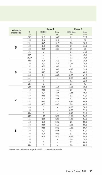
Xtra·tec® Insert Drill 55
Indexable insert size
Range 1 Range 2Dc
mmDelta x
mmDmaxmm
Delta xmaxmm
Dmaxmm
5
29,5 0,7 30,9 1,1 31,730 0,6 31,2 1 3231 0,45 31,9 0,8 32,632 0,3 32,6 0,7 33,433 0,15 33,3 0,5 3434 0 – 0,4 34,8
35* 0 – 0,3 35,635,4* 0 – 0,2 35,8
6
35,5 0,8 37,1 1,4 38,336 0,7 37,4 1,25 38,537 0,55 38,1 1,1 39,238 0,4 38,8 0,95 39,939 0,25 39,5 0,8 40,640 0,1 40,2 0,65 41,341 0 – 0,55 42,142 0 – 0,4 42,8
42,4 0 – 0,3 43
7
42,5 0,95 44,4 1,65 45,843 0,85 44,7 1,5 4644 0,7 45,4 1,35 46,745 0,55 46,1 1,2 47,446 0,4 46,8 1,1 48,247 0,25 47,5 0,95 48,948 0,15 48,3 0,8 49,649 0 – 0,65 50,350 0 – 0,55 51,1
50,4 0 – 0,45 51,3
8
50,5 1,05 52,6 1,85 54,251 0,95 52,9 1,75 54,552 0,8 53,6 1,6 55,253 0,65 54,3 1,45 55,954 0,55 55,1 1,35 56,755 0,4 55,8 1,2 57,456 0,3 56,6 1,1 58,257 0,15 57,3 0,95 58,958 0 – 0,8 59,659 0 – 0,7 60,4
59,4 0 – 0,6 60,6
* Outer insert with wiper edge (P4840P . . ) can only be used 2x

56
Tool diameter tolerance ranges for Xtra ·tec® Insert Drill B421x
0,050,08
–0,08
0,15*
–0,15*
–0,05
00,05
0,10
–0,05
0,15
0,20
–0,20
–0,15
–0,10
0
0,3
–0,1
∆D[mm]
Walter Insert DrillB 4212, B 4213Ø 13,5–59 mm
Sleeve adapter S 2131, 2132, 2133, 2165
* ± 0,17 for insert size 7 ± 0,19 for insert size 8
Drill type Tolerance range
Nominal adjustment range
Body tolerance
without sleeve adapter
with sleeve adapter
The resulting workpiece diameter may differ due to the drilling depth, workpiece material, feed rate and chip removal conditions.
Master insert
Ground insert P 4840
Sintered insert P 4841

Xtra·tec® Insert Drill 57
Recommended values for Xtra ·tec® Insert Drill B421x
01
0204
03
Symbol for centre insert
Outer insertP 484 . P
Centre insertP 484 . C
Outer inserts now in Tiger·tec® Silver
Centre inserts in Tiger·tec® Silver and WXP40
UseCutting edge identification for 1st to 4th use

58
Recommended values for Xtra ·tec® Insert Drill B421x
2,5
2
P [bar]
Dc [mm]13,51,5
Ø 14Ø 12
3020 40 100
4
3,5
3
5,5
5
4,5
15 50 60 70 80 90
Coolant pressure for horizontal machining direction
L = 5xDc
L = 4xDc
L = 3xDc
L = 2xDc
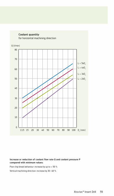
Xtra·tec® Insert Drill 59
Increase or reduction of coolant flow rate Q and coolant pressure P compared with minimum values:
Poor chip break behaviour: increase by up to + 50 %
Vertical machining direction: increase by 30 – 40 %
20
10
Q [l/min]
Dc [mm]0
Ø 14Ø 12
50
40
30
80
70
60
13,5 3020 40 10015 50 60 70 80 90
Coolant quantity for horizontal machining direction
L = 5xDc
L = 4xDc
L = 3xDc
L = 2xDc

60
Recommended values for drillingXtra ·tec® Insert Drill B421xMaterial: C45 – (1.0503) steel, steel casting [Rm = 650 N/mm²]
Dc [mm]
0,04
P [kW]
f [mm/rev]0,05 0,06 0,08 0,10 0,12 0,16 0,20 0,25
Ø 120Ø 100Ø 80Ø 60Ø 50Ø 40Ø 30Ø 25
Ø 20
Ø 16
0,30
Ø 13,5
4,0
2,0
8,0
16,0
1,0
0,5
32,0
64,0
0,8
0,6
1,3
1,6
3,22,5
5,06,3
10,112,7
20,225,4
40,350,8
Power requirement 1
Dc [mm]
0,04 f [mm/rev]0,05 0,06 0,08 0,10 0,12 0,16 0,20 0,25 0,30
F [N]
Ø 120Ø 100Ø 80Ø 60Ø 50Ø 40Ø 30Ø 25
Ø 20
Ø 16
Ø 13,5
2000
1000
4000
8000
500
250
16000
32000
315397
630794
12601587
25203175
50406350
1007912699
2015925398
Feed force

Xtra·tec® Insert Drill 61
The power requirement 1 data is based on a cutting speed of 100 m/min.
If the cutting speed is doubled, the power requirement also doubles, i.e. the power requirement is directly proportional to the cutting speed.
For steels with a higher tensile strength, the power and torque required are correspondingly higher.
Dc [mm]
0,04 f [mm/rev]0,05 0,06 0,08 0,10 0,12 0,16 0,20 0,25 0,30
Mc [Nm]
Ø 120
Ø 100
Ø 80
Ø 60
Ø 50
Ø 40
Ø 30
Ø 25
Ø 20
Ø 16
Ø 13,5
1,0
2,0
4,0
8,0
16
32
64
128
256
512
1024
2048
1626
1290
813
645
406
323
203
161
102
81
51
40
25
20
13
10
6,3
5,0
3,2
2,5
1,6
1,3
Torque

62
Recommended values for drillingXtra ·tec® Insert Drill B421xMaterial: 42CrMo4 – Cr-Mo alloyed heat treatable steel
[Rm = 750–900 N/mm²]
Dc [mm]
0,04
P [kW]
f [mm/rev]0,05 0,06 0,08 0,10 0,12 0,16 0,20 0,25
Ø 120Ø 100Ø 80Ø 60Ø 50Ø 40Ø 30Ø 25
0,30
4,0
2,0
8,0
16,0
1,0
0,5
32,0
64,0
0,8
0,6
1,3
1,6
3,22,5
5,06,3
10,112,7
20,225,4
40,350,8
Ø 20
Ø 16Ø 13,5
Power requirement 1
Dc [mm]
0,04 f [mm/rev]0,05 0,06 0,08 0,10 0,12 0,16 0,20 0,25 0,30
F [N]
Ø 120Ø 100Ø 80Ø 60Ø 50Ø 40Ø 30Ø 25
Ø 20
2000
1000
4000
8000
500
250
16000
32000
315397
630794
12601587
25203175
50406350
1007912699
2015925398
Ø 16Ø 13,5
Ø 20
Feed force

Xtra·tec® Insert Drill 63
Dc [mm]
0,04 f [mm/rev]0,05 0,06 0,08 0,10 0,12 0,16 0,20 0,25 0,30
Mc [Nm]
Ø 120
Ø 100
Ø 80
Ø 60
Ø 50
Ø 40
Ø 30
Ø 25
1,0
2,0
4,0
8,0
16
32
64
128
256
512
1024
2048
1626
1290
813
645
406
323
203
161
102
81
51
40
25
20
13
10
6,3
5,0
3,2
2,5
1,6
1,3
Ø 20
Ø 16
Ø 13,5
Torque
The power requirement 1 data is based on a cutting speed of 100 m/min.
If the cutting speed is doubled, the power requirement also doubles, i.e. the power requirement is directly proportional to the cutting speed.
For steels with a higher tensile strength, the power and torque required are correspondingly higher.

64
Recommended values for drillingXtra ·tec® Insert Drill B421xMaterial: GG25 – (0.6025) cast iron, ferritic [180-200 HB]
Dc [mm]
0,04
P [kW]
f [mm/rev]0,05 0,06 0,08 0,10 0,12 0,16 0,20 0,25
Ø 120Ø 100Ø 80Ø 60Ø 50Ø 40Ø 30Ø 25
0,30
4,0
2,0
8,0
16,0
1,0
0,5
32,0
64,0
0,8
0,6
1,3
1,6
3,22,5
5,06,3
10,112,7
20,225,4
40,350,8
Ø 20
Ø 16Ø 13,5
Power requirement 1
Dc [mm]
0,04 f [mm/rev]0,05 0,06 0,08 0,10 0,12 0,16 0,20 0,25 0,30
F [N]
Ø 120Ø 100Ø 80Ø 60Ø 50Ø 40Ø 30Ø 25
2000
1000
4000
8000
500
250
16000
32000
315397
630794
12601587
25203175
50406350
1007912699
2015925398
Ø 20
Ø 13,5Ø 16
Feed force
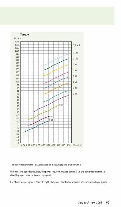
Xtra·tec® Insert Drill 65
Dc [mm]
0,04 f [mm/rev]0,05 0,06 0,08 0,10 0,12 0,16 0,20 0,25 0,30
Mc [Nm]
Ø 120
Ø 100
Ø 80
Ø 60
Ø 50
Ø 40
Ø 30
Ø 25
1,0
2,0
4,0
8,0
16
32
64
128
256
512
1024
2048
1626
1290
813
645
406
323
203
161
102
81
51
40
25
20
13
10
6,3
5,0
3,2
2,5
1,6
1,3
Ø 20
Ø 16
Ø 13,5
Torque
The power requirement 1 data is based on a cutting speed of 100 m/min.
If the cutting speed is doubled, the power requirement also doubles, i.e. the power requirement is directly proportional to the cutting speed.
For steels with a higher tensile strength, the power and torque required are correspondingly higher.

66
Recommended values for drillingXtra ·tec® Insert Drill B421xMaterial: GGG70 – (0.7070) cast iron with spheroidal graphite [Rm = 690 N/mm²]
Dc [mm]
0,04
P [kW]
f [mm/rev]0,05 0,06 0,08 0,10 0,12 0,16 0,20 0,25
Ø 120Ø 100Ø 80Ø 60Ø 50Ø 40Ø 30Ø 25
0,30
4,0
2,0
8,0
16,0
1,0
0,5
32,0
64,0
0,8
0,6
1,3
1,6
3,22,5
5,06,3
10,112,7
20,225,4
40,350,8
Ø 20
Ø 16Ø 13,5
Power requirement 1
Dc [mm]
0,04 f [mm/rev]0,05 0,06 0,08 0,10 0,12 0,16 0,20 0,25 0,30
F [N]
Ø 120Ø 100Ø 80Ø 60Ø 50Ø 40Ø 30Ø 25
2000
1000
4000
8000
500
250
16000
32000
315397
630794
12601587
25203175
50406350
1007912699
2015925398
Ø 20
Ø 16
Ø 13,5
Feed force

Xtra·tec® Insert Drill 67
Dc [mm]
0,04 f [mm/rev]0,05 0,06 0,08 0,10 0,12 0,16 0,20 0,25 0,30
Mc [Nm]
Ø 120
Ø 100
Ø 80
Ø 60
Ø 50
Ø 40
Ø 30
Ø 25
1,0
2,0
4,0
8,0
16
32
64
128
256
512
1024
2048
1626
1290
813
645
406
323
203
161
102
81
51
40
25
20
13
10
6,3
5,0
3,2
2,5
1,6
1,3
Ø 20
Ø 16
Ø 13,5
Torque
The power requirement 1 data is based on a cutting speed of 100 m/min.
If the cutting speed is doubled, the power requirement also doubles, i.e. the power requirement is directly proportional to the cutting speed.
For steels with a higher tensile strength, the power and torque required are correspondingly higher.

68
Chain drillingIf problems occur – Reduce feed by 30 %
Unmachined and stepped surfacesIf the drill entry angle > 30° – Reduce feed by 50 % during entry
Interrupted cutProblems with interrupted cut– Feed < 30 %
Angled entry drillingReduce feed by 30 % during entry
Cross holesReducing the feed by 30 % achieves the best results
Stack drillingIs not possible
Application possibilities for Xtra ·tec® Insert Drill

Xtra·tec® Insert Drill 69
Problem solutions
Inner cutting edge breaks
– Check machine alignment (lathe)– Check workpiece clamping and ensure
that there is max. tool stability– Use tougher carbide grade– Reduce feed values by 50 –70 %
Chip removal not efficient
– Select optimum indexable insert geometry
– Increase coolant pressure– Increase cutting speed by 20 %– Optimise chip breaking by increasing
feed by ~10 %
Excessive insert wear
– Reduce cutting speed by 20 %– Increase coolant pressure– Use more wear-resistant carbide
grade, e.g. WKP25 instead of WKP35
Poor surface quality
– Increase coolant pressure– Improve clamping situation of work-
piece and tool– Increase cutting speed by 20 %– Reduce feed by 10 %

f
n
Vf
70
Drilling calculation formulae
Speedn [rpm]
Cutting speedvc [m/min]
Feed per revolutionf [mm]
Feed ratevf [mm]
Metal removal rateQ [cm³/min]
Power requirementPmot [kW]
Feed forceFf [N]
Specific cutting forcekc [N/mm²]
Chip thicknessh [mm]
TorqueMc [Nm]

Xtra·tec® Insert Drill 71

72
Cutting forces of Walter machining groups
Cutting forces
Description
Tensile strength Spec. cutting force Increase value Walter
machining groupmin max
Rm kc1.1 mc
[N/mm²] [N/mm²]
Non-alloyed and low-alloy steels, C > 0,25 %, low and medium strength 350 750 1500 0,21 P1, P6
Unalloyed and low-alloy steels, C > 0,55 %, not heat treated 400 900 1700 0,25 P2, P3, P4, P7, P14
Low and high-alloy steels, low tempering level 750 1100 2000 0,25 P5, P8, P11, P12
Stainless ferritic/martensitic steels, heat treated 800 1400 2200 0,25 P15
Low and high-alloy steels, medium tempering level 1100 1400 2500 0,25 P9
Low and high-alloy steels, high tempering level 1200 1600 3000 0,25 P10, P13
Stainless, austenitic steels 400 900 1800 0,21 M1
Stainless, austenitic/ferritic steel + duplex 600 1000 2000 0,21 M3
Stainless, austenitic steels, precipitation hardened (PH steels) 700 1500 2400 0,21 M2
Grey cast iron + CGI + malleable cast iron, low tensile strength 200 400 800 0,28 K1, K3, K7
Ductile cast iron low tensile strength + malleable cast iron with higher tensile strength 400 600 950 0,28 K2, K5
Grey cast iron with higher tensile strength 300 400 1200 0,28 K4,
Ductile cast iron with high tensile strength + ADI high tensile strength, unalloyed + alloyed 600 800 1400 0,28 K6
Aluminium wrought alloy, not precipitation hardened 350 0,25 N1
Aluminium wrought alloy, precipitation hardened 600 0,25 N2
Cast aluminium alloy < 12 % Si, not precipitation hardened 600 0,25 N3
Cast aluminium alloy < 12 % Si, precipitation hardened, cast aluminium alloy ≥ 12 % 700 0,25 N4, N5
Pure copper, copper alloy (brass, bronze) with low tensile strength 550 0,25 N7, N8, N9
High tensile strength copper alloy, bronze with high tensile strength 1000 0,25 N10
Heat-resistant alloys, iron-based, annealed 2400 0,25 S1
Heat-resistant alloys, iron-based, precipitation hardened 2500 0,25 S2
Pure titanium 1300 0,25 S6
Titanium alloys, alpha, alpha/beta and beta alloys 1500 0,25 S7, S8
Heat-resistant alloys, nickel-cobalt-based, annealed 2800 0,25 S3
Heat-resistant alloys, nickel-cobalt-based, precipitation hardened 2900 0,25 S4
Heat-resistant alloys, nickel-cobalt-based, cast 3000 0,25 S5
Hardened steels 46 – 52 HRC 3000 0,25 H1
Hardened steels 52 – 58 HRC 3700 0,25 H2
Hardened steels 58 – 62 HRC 4300 0,25 H3
Hardened cast iron 50 – 60 HRC 3500 0,25 H4
Thermoplasts and duroplasts, without abrasive fillers 150 0,2 O1, O2
Fibre-reinforced plastics 300 0,3 O3, O4, O5
Graphite 400 0,25 O6
Comments:The information consists of guideline values and relates to neutral cutting edge geometry. The condition of the workpiece material and the cutting edge geometry have considerable influence on the cutting forces.

Xtra·tec® Insert Drill 73
Cutting forces
Description
Tensile strength Spec. cutting force Increase value Walter
machining groupmin max
Rm kc1.1 mc
[N/mm²] [N/mm²]
Non-alloyed and low-alloy steels, C > 0,25 %, low and medium strength 350 750 1500 0,21 P1, P6
Unalloyed and low-alloy steels, C > 0,55 %, not heat treated 400 900 1700 0,25 P2, P3, P4, P7, P14
Low and high-alloy steels, low tempering level 750 1100 2000 0,25 P5, P8, P11, P12
Stainless ferritic/martensitic steels, heat treated 800 1400 2200 0,25 P15
Low and high-alloy steels, medium tempering level 1100 1400 2500 0,25 P9
Low and high-alloy steels, high tempering level 1200 1600 3000 0,25 P10, P13
Stainless, austenitic steels 400 900 1800 0,21 M1
Stainless, austenitic/ferritic steel + duplex 600 1000 2000 0,21 M3
Stainless, austenitic steels, precipitation hardened (PH steels) 700 1500 2400 0,21 M2
Grey cast iron + CGI + malleable cast iron, low tensile strength 200 400 800 0,28 K1, K3, K7
Ductile cast iron low tensile strength + malleable cast iron with higher tensile strength 400 600 950 0,28 K2, K5
Grey cast iron with higher tensile strength 300 400 1200 0,28 K4,
Ductile cast iron with high tensile strength + ADI high tensile strength, unalloyed + alloyed 600 800 1400 0,28 K6
Aluminium wrought alloy, not precipitation hardened 350 0,25 N1
Aluminium wrought alloy, precipitation hardened 600 0,25 N2
Cast aluminium alloy < 12 % Si, not precipitation hardened 600 0,25 N3
Cast aluminium alloy < 12 % Si, precipitation hardened, cast aluminium alloy ≥ 12 % 700 0,25 N4, N5
Pure copper, copper alloy (brass, bronze) with low tensile strength 550 0,25 N7, N8, N9
High tensile strength copper alloy, bronze with high tensile strength 1000 0,25 N10
Heat-resistant alloys, iron-based, annealed 2400 0,25 S1
Heat-resistant alloys, iron-based, precipitation hardened 2500 0,25 S2
Pure titanium 1300 0,25 S6
Titanium alloys, alpha, alpha/beta and beta alloys 1500 0,25 S7, S8
Heat-resistant alloys, nickel-cobalt-based, annealed 2800 0,25 S3
Heat-resistant alloys, nickel-cobalt-based, precipitation hardened 2900 0,25 S4
Heat-resistant alloys, nickel-cobalt-based, cast 3000 0,25 S5
Hardened steels 46 – 52 HRC 3000 0,25 H1
Hardened steels 52 – 58 HRC 3700 0,25 H2
Hardened steels 58 – 62 HRC 4300 0,25 H3
Hardened cast iron 50 – 60 HRC 3500 0,25 H4
Thermoplasts and duroplasts, without abrasive fillers 150 0,2 O1, O2
Fibre-reinforced plastics 300 0,3 O3, O4, O5
Graphite 400 0,25 O6
Comments:The information consists of guideline values and relates to neutral cutting edge geometry. The condition of the workpiece material and the cutting edge geometry have considerable influence on the cutting forces.

74
Notes

Prin
ted
in G
erm
any
625
6469
(05
/201
2) E
N
Walter AG
Derendinger Straße 53, 72072 Tübingen Postfach 2049, 72010 Tübingen Germany www.walter-tools.com www.facebook.com/waltertools www.youtube.com/waltertools
Walter GB LTD. Bromsgrove, England 44 (1527) 839 450, [email protected] Walter Wuxi Co. Ltd. Wuxi, Jiangsu, P.R. China +86 (510) 8241 9399, [email protected] Walter AG Singapore Pte. Ltd. +65 6773 6180, [email protected] Walter Korea Ltd. Ansan, Kyungki-do, Korea +82 (31) 3646 100, [email protected] Walter Tools India Pvt. Ltd. Pune, India +91 (20) 3045 7300, [email protected] Walter (Thailand) Co., Ltd. Bangkok, 10120, Thailand +66 2 687 0388, [email protected] Walter Malaysia Sdn. Bhd. Selangor D.E., Malaysia +60 (3) 8023 7748, [email protected] Walter Australia Pty. Ltd. Hallam, Victoria 3803, Australia +61 3 8793 1000, [email protected] Walter Tooling Japan K.K. Nagoya, Japan +81 (52) 723 5800, [email protected] Walter USA, LLC Waukesha WI, USA +1 800-945-5554, [email protected] Walter Canada Mississauga, Canada [email protected]