Embed Size (px)
DESCRIPTION
piezoelectric
Citation preview

MAE 656: Advanced computer
aided design
Tomás Muchenik
Design of piezoelectric cantilevers
Morgantown, WV, 08 10 2012

Presentation
Description of the problem solved
Description of the numerical model
Results obtained with the numerical model
Conclusions and summary
2

Description of the problem solved
3

Description of the problem solved
Piezoelectric materials:
4

Description of the problem solved
Piezoelectric cantilevers:
5
[5]

Description of the problem solved
Applications for this cantilevers:
Accelerometers [1].
AFM cantilevers [2].
Harvesters [3].
In all this applications the mechanical resonance frequency is a key parameter.
6
[5]

Description of the problem solved
The goal of this project is to develop a design criterion.
Evaluate the change in stresses
when the length and the width is
changed.
Advantage: the resonance frequency
can be tuned without increasing the
internal loads.
7
Description of the problem solved
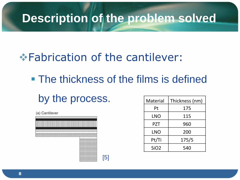
Fabrication of the cantilever:
The thickness of the films is defined
by the process. Material Thickness (nm)
Pt 175
LNO 115
PZT 960
LNO 200
Pt/Ti 175/5
SiO2 540
8
[5]

Description of the problem solved
Fabrication of the cantilever:
9
[6]

Description of the problem solved
In this project the cantilever made by Kobayashi et.al. [5] will be modeled to know what are the stresses that the materials can support without breaking.
10
Cantilever dimensions:
270x1000µm
[5]

Description of the numerical model
11

Description of the numerical model
Loads over the cantilever:
Gravitational.
Process loads*.
Loads during the application*.
12
*: not considered in this work

Support:
The cantilever will be supported in
the lateral faces.
13
Description of the numerical model
[5]

Geometry approximation:
Only one width and length will be
used for all the layers.
The Ti layer (5nm) won’t be modeled
because is an adhesion layer.
14
Description of the numerical model
[5]

3D Modeling:
In this case we are in the limit were
3D modeling can be used because
the smallest lamina dimensions are
1000x270x0.1µm.
15
Description of the numerical model

Materials properties:
16
Description of the numerical model
Density
(g/cm3)
Elastic Modulus
(Gpa)
Poisson's
ratio Ref.
SiO2 2.2 69 0.17 [7]
Pt 21.44 164.6 0.396 [8]
LNO 4.8 69* 0.17* [9]
PZT 7.6 101 0.3 [10]
*the properties of LNO couldn’t be found and they were replaced for the SiO2
properties.

Meshing:
First the automatic meshing.
Secondly, mapping and face sizing.
17
Description of the numerical model

Meshing:
Convergence study: problem with the
aspect ratio of the elements (Thickness:
0.1µm). e.g. 16x16x0.1µm
18
Description of the numerical model
Upper size of the square
nodes (µm) Amount of nodes
Directional
deformation (µm)
Maximum stress in X
direction (Mpa)
Minimum stress in X
direction (Mpa)
16 29572 2.38E-01 0.2063 0.141
17 27001 2.39E-01 0.2063 0.14095
18 24113 2.39E-01 0.20621 0.14087
19 21387 2.39E-01 0.20631 0.14092
20 20193 2.39E-01 0.20645 0.141
21 18081 2.39E-01 0.20629 0.14088
22 15733 2.38E-01 0.20598 0.14064

Results obtained with the numerical model
19

Deformation and stresses:
20
Results obtained with the numerical
model

As explained before different lengths
and widths were used and the
deformation and stresses were
calculated:
Lengths varied from 600 to 1400 µm.
Widths varied from 230 to 310 µm.
21
Results obtained with the numerical
model
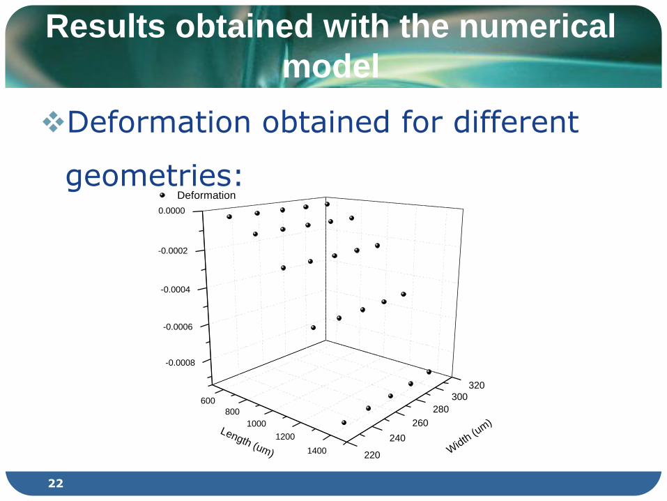
Deformation obtained for different
geometries:
22
Results obtained with the numerical
model
600
800
1000
1200
1400
-0.0008
-0.0006
-0.0004
-0.0002
0.0000
220
240
260
280
300
320
Deformation
Width
(um
)Length (um)

Stresses obtained for different
geometries:
23
Results obtained with the numerical
model
600
900
1200
1500
0.05
0.10
0.15
0.20
0.25
0.30
0.35
0.40
0.45
240
270
300
Ma
xim
um
Str
esse
s (
MP
a)
Width
(um
)Length (um)
24
Results obtained with the numerical
model
Future work:
Develop a shell model to validate the
results obtained.

Conclusions and summary
25

The working mechanism and
applications of piezoelectric
cantilevers was explained.
The fabrication processes was
summarized in order to know the
real applied loads.
26
Conclusions and summary

A model of the cantilever designed by Kobayashi et.al. [5] was made and the meshing was verified.
Approximations made:
Applied loads.
Materials used.
Geometry (width and Ti layer).
27
Conclusions and summary

A design criterion to change the resonance frequency was developed:
The width doesn’t have a significant
influence in the internal stresses or the
deformation.
The internal stresses and the
deformations increase when the length
increase.
28
Conclusions and summary

[1]: Sensors and Actuators, A92 (2001) 156-160.
[2]: Sensors and Actuators, A72 (1999) 179-188.
[3]: Applied Physics Letters, V84 N16 (2004) 3187-3189.
[4]: Meas. Sci. Technol. 17 (2006) R175-R195.
[5]: Thin Solid Films 516 (2008) 5272-5276.
[6]: Sensors and Actuators A117 (2005) 1-7
[7]: IEEE Transactions on electron
devices,Vol.ED25,No.10,Oct1978, p.1249.
[8]: Platinum Metals Rev., 2001, 45, (2), 74-82.
[9]: A. Yamada, Journal of power Sources 119-121 (2003) 232-238.
[10]: Mat. Res. Soc. Symp. Proc. Vol. 687, 2002 Materials Research
Society.
29
References