Embed Size (px)
DESCRIPTION
Project uC
Citation preview
______________________________________________________________________
1
USB interface for data recording
from the heat meter
TECHNICAL UNIVERSITY OF LIBEREC
Faculty of Mechatronics, Informatics and Interdisciplinary Studies
Study program: N2612 – Electrical Engineering and Informatics
Branch: 2612T071 – Engineering of Interactive systems
USB interface for data recording from the heat
meter
Semestral project
Author: Tomáš MAREK
Project Supervisor: Ing. Lubomír Slavík
Liberec 28.5.2010
2
USB interface for data recording
from the heat meter
TECHNICAL UNIVERSITY OF LIBEREC
Faculty of Mechatronics, Informatics and Interdisciplinary Studies
Institute of Information Technology and Electronics Academic year: 2009/2010
SEMESTRAL PROJECT
Name: Bc. Tomáš Marek
Program: Electrical Engineering and Informatics
Branch: Engineering of Interactive Systems
Project Name:
USB interface for data recording from the heat meter
Project Supervisor: Ing. Lubomír Slavík
Tasks:
1. Study principle of USB communication
2. Study materials and datasheets of USB circuits of FTDI company and
microcontrollers PIC of Microchip company
3. Design and realize interface module RS232/USB of mass storage type
Literature:
[1] HRBÁČEK, J.: Modern programming of microcontrollers PIC. BEN, Praha 2004,
ISBN 80-7300-136-5
[2] MATOUŠEK, D.: USB in practice with FTDI circuits. BEN, Praha 2003,
ISBN 80-7300-103-9
[3] Datasheets of circuits Vinculum. URL:<www.vinculum.com>
[4] Datasheets of PIC microcontrollers. URL:<www.microchip.com>
Final Report Size: from 10 to 15 pages
In Liberec 9. 3. 2010 Project Supervisor (signature)..................................
3
USB interface for data recording
from the heat meter
Abstract
The aim of this project is to create interface for data storage from the double heat
meter MT200DS. Heat meter stores a lot of different data such as values from all
sensors or different working conditions to the day, month and year archive. These data
are stored in the on board implemented EEPROM data memory. From the heat meter is
also possible to obtain and store only actual values. In this project there is solved the
problem of actual values storage. As a memory medium was chosen today widely used
USB key (mass storage based on the flash memory). Data transaction between heat
meter and the memory is managed by microcontroller PIC18f452 (Microchip). Because
this microcontroller does not support USB directly, it was necessary to use some
converter. For this reason is used converter VNC1L (FTDI), which includes also
advanced features thanks to implemented firmware. VNC1L is placed on the module
VDIP2 for rapid prototyping. The module was in the end implemented with the
microcontroller on one board to provide an USB interface for the heat meter.
Key words:
VNC1L, VDIP2, Universal Serial Bus, data storage
4
USB interface for data recording
from the heat meter
Contents
Terms and Abbreviations .............................................................................. 6
1. Introduction ................................................................................................... 7
2. Universal Serial Bus ..................................................................................... 8
1.1. Brief history .......................................................................................... 8
1.2. Hardware description ............................................................................ 9
1.3. Electrical description ............................................................................ 9
1.4. Voltage levels ..................................................................................... 11
1.5. Topology ............................................................................................. 12
1.6. USB transaction .................................................................................. 13
1.1.1. Introduction .................................................................................... 13
1.1.2. Common packet fields: .................................................................. 13
1.1.3. Types of USB Packets: .................................................................. 14
3. VDIP2 module ............................................................................................ 16
1.7. Introduction ......................................................................................... 16
1.8. Communication ................................................................................... 17
1.1.4. UART ............................................................................................. 17
1.1.5. SPI .................................................................................................. 18
1.1.6. FIFO ............................................................................................... 18
1.9. VNC1L chip ........................................................................................ 19
1.1.7. Basic features of the VNCL1 ......................................................... 19
1.1.8. Firmware ........................................................................................ 20
1.1.9. Upgrading firmware ....................................................................... 23
4. Heat meter ................................................................................................... 23
1.10. General description ............................................................................. 23
1.11. Communication ................................................................................... 24
1.1.10. RS232 interface ............................................................................ 25
1.1.11. RS232 interface module with analogue output ............................ 25
1.12. Communication protocols ................................................................... 25
5
USB interface for data recording
from the heat meter
1.1.12. Simple .......................................................................................... 26
1.1.13. BitBus .......................................................................................... 27
1.1.14. Data archive ................................................................................. 28
5. Prototype board ........................................................................................... 29
6. Software ...................................................................................................... 30
1.13. Description of used software tools ...................................................... 30
1.14. Created functions ................................................................................ 31
1.15. Main program ..................................................................................... 33
7. Conclusion .................................................................................................. 33
Literature ..................................................................................................... 35
Appendix A - PCB ...................................................................................... 36
Appendix B - file......................................................................................... 38
Acknowledgement:
This text grew up by support of project ESF CZ.1.07/2.2.00/07.0247 Reflexe
požadavků průmyslu na výuku v oblasti automatického řízení a měření.
6
USB interface for data recording
from the heat meter
Terms and Abbreviations
EEPROM Electrically Erasable Programmable Read-Only Memory USB Universal Serial Bus FTDI Future Technology Devices Int. Ltd. VNC1L Name of the chip (also called Vinculum) VDIP2 Name of the module based on VNC1L VMSC Name of the firmware USB-IF USB Implementers Forum WinHec Windows Hardware Engineering Conference HID Human Interface Devices NRZI Non Return to Zero Inverted SE0 Single Ended Zero PID Package Identifier LVTTL Low Voltage Transistor Transistor Logic TTL Transistor Transistor Logic I/O Input/Output BOMS Bulk Only Mass Storage CDC Communication Device Class HID Human Input Device PCB Printed Circuit Board
7
USB interface for data recording
from the heat meter
1. Introduction
The main task was to store data from the heat meter. Today are well known and
widely spread flash memories (USB keys) – nearly everyone who has the computer has
at least one USB key. This memory provides very big data space for very low price in
my point of view. The only problem used to be the USB interface, because it is not so
easy to deal with the USB protocol in an ordinary microprocessor. To solve this
problem efficiently in the world were developed some 'clever' integrated circuits, which
provide functions for USB communication. One of these chips is VNCL1. VNCL1 is
implemented on the module called VDIP2, which is useful for rapid prototyping.
Module is connectable thanks to its compatibility with standard 40pin DIP socket.
VNC1L contains host controller, which means, that it can manage all USB
communication without any PC. Many other applications are available and depend
mostly on the implemented firmware. There are six different firmwares provided by the
manufacturer (FTDI). For example typical application of the VMSC firmware should be
reading music data from USB key and sending them via decoder to the headphones. In
the same time should be controlled volume by external microcontroller, which uses
access to the VNC1L via monitor command interface. Other possibility is to send data
from USB key to the USB printer via VNC1L. It is also possible to connect keyboard
and send data directly from keyboard to the printer. Sending data from one USB key to
another is also available with the VDFC firmware. In this application is used basic
VDAP firmware, which supports data transfers with USB keys (or USB hard disk
drives). To control the function of VNC1L are used commands, which are sent via
RS232, SPI or FIFO interface from the microcontroller. These commands can be sent
like ASCII characters (IPA mode) or like hex code values (IPH mode). There can be
chosen Shortened Command Set (SCS) or for more functionality Extended
Command Set (ECS).
As written above VNC1L is very powerful chip and it can be used in many
different ways. This work shows only one small part of possible usage.
8
USB interface for data recording
from the heat meter
2. Universal Serial Bus
1.1. Brief history
History of the Universal Serial Bus (USB) is quite short compare to RS232 for
example. Development started in 1994 by effort of six companies – IBM, Compaq,
Intel, Microsoft, NEC, Nortel and DEC. The first idea was to develop universal bus
simple to use with small and compact connectors (to reduce many connectors in the
personal computers). To have a possibility to connect devices such as digital cameras,
webcams (or any other devices with big data transfers in a short time), there was also
requirement for high transfer speeds.
1995 – USB Implementers Forum (USB-IF) was formed on the First Windows
Hardware Engineering Conference (WinHec). During this conference Intel
introduced first USB silicon.
1996 – USB Specification 1.0 was released.
1997 – membership increased in the USB-IF to 400 members. In the world was
developed more than 500 USB products this year.
2000 – USB 2.0 was released
2001 – standardization of USB 2.0 by USB-IF
2008 – USB 3.0 announced by USB 3.0 Promoter Group
Low speed and Full speed baud rates were included in the USB 1.1 specification.
High speed came with USB 2.0 in the year 2000. High speed USB was some attack to
compete with Firewire Serial Bus (IEEE1394a), which was developed and presented in
1995 by Apple. It was basically developed for big data transfers (e.g. digital video
transfers), so the baud rates were 100, 200, or 400 Mbit/s . In 1995 Firewire had no
competitors, because USB 1.0 could not compete with it. USB 2.0 was little bit faster
than Firewire400, but it was changed in the year 2002 by presenting Firewire800
(IEEE1394b with maximal baud rate 800 Mbit/s).
9
USB interface for data recording
from the heat meter
1.2. Hardware description
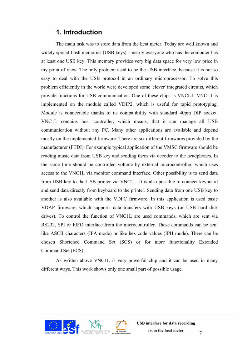
On the Fig. 1 are shown the three most used types of USB connectors. Typically
we can find sockets type ‘A’ on the computer main boards and on the hubs. Type ‘B’
sockets are situated on the devices (‘B’ plugs are always connected downstream). So
Fig. 1: USB connectors (source [1])
the upstream and downstream connectors are not mechanically interchangeable. Cables,
where are e.g. both connectors of the same type, are prohibited by the specification
(except cables for bridges used to connect two computers together). Because type ‘B’
connector is not suitable for small devices (because of its size), mini-usb ‘B’ connectors
were developed. In the Table 1 there is shown connection of the pins.
Pin Name Cable color Description1 Vcc Red +5 V DC2 D- White Data-3 D+ Green Data+4 GND Black Groundx may not be used, connected to GND
or used as attachment identification for some devices
Table 1: Description of the USB pins
1.3. Electrical description
Voltage levels of the USB communication depend of course on the baud rate. In
the USB specification are defined three different baud rates:
Low speed – 1,5 Mbit/s Full speed – 12 Mbit/s High speed – 480 Mbit/s
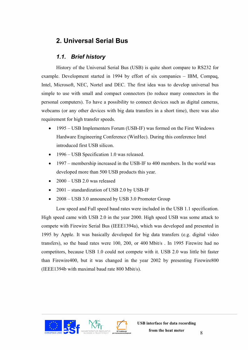
Low speed is usually used for HIDs (Human Interface Devices) like a mouse,
joystick, keyboard. USB cable contains four wires. On the borders are wires VBUS and
GND, in the center is twisted pair marked as D+ and D- (see Fig. 2). Power supply
wires (VBUS and GND) are useful, because smaller devices can be powered directly
10
USB interface for data recording
from the heat meter
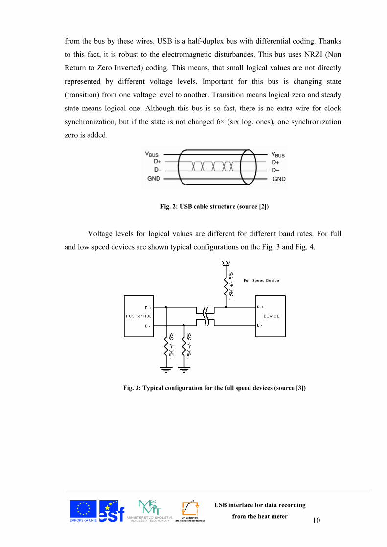
from the bus by these wires. USB is a half-duplex bus with differential coding. Thanks
to this fact, it is robust to the electromagnetic disturbances. This bus uses NRZI (Non
Return to Zero Inverted) coding. This means, that small logical values are not directly
represented by different voltage levels. Important for this bus is changing state
(transition) from one voltage level to another. Transition means logical zero and steady
state means logical one. Although this bus is so fast, there is no extra wire for clock
synchronization, but if the state is not changed 6× (six log. ones), one synchronization
zero is added.
Fig. 2: USB cable structure (source [2])
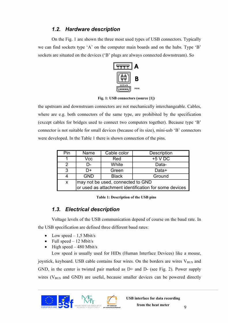
Voltage levels for logical values are different for different baud rates. For full
and low speed devices are shown typical configurations on the Fig. 3 and Fig. 4.
Fig. 3: Typical configuration for the full speed devices (source [3])
11
USB interface for data recording
from the heat meter
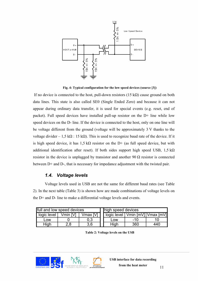
Fig. 4: Typical configuration for the low speed devices (source [3])
If no device is connected to the host, pull-down resistors (15 kΩ) cause ground on both
data lines. This state is also called SE0 (Single Ended Zero) and because it can not
appear during ordinary data transfer, it is used for special events (e.g. reset, end of
packet). Full speed devices have installed pull-up resistor on the D+ line while low
speed devices on the D- line. If the device is connected to the host, only on one line will
be voltage different from the ground (voltage will be approximately 3 V thanks to the
voltage divider – 1,5 kΩ : 15 kΩ). This is used to recognize baud rate of the device. If it
is high speed device, it has 1,5 kΩ resistor on the D+ (as full speed device, but with
additional identification after reset). If both sides support high speed USB, 1,5 kΩ
resistor in the device is unplugged by transistor and another 90 Ω resistor is connected
between D+ and D-, that is necessary for impedance adjustment with the twisted pair.
1.4. Voltage levels
Voltage levels used in USB are not the same for different baud rates (see Table
2). In the next table (Table 3) is shown how are made combinations of voltage levels on
the D+ and D- line to make a differential voltage levels and events.
full and low speed devices high speed deviceslogic level Vmin [V] Vmax [V] logic level Vmin [mV] Vmax [mV]
Low 0 0,3 Low -10 10High 2,8 3,6 High 360 440
Table 2: Voltage levels on the USB
12
USB interface for data recording
from the heat meter
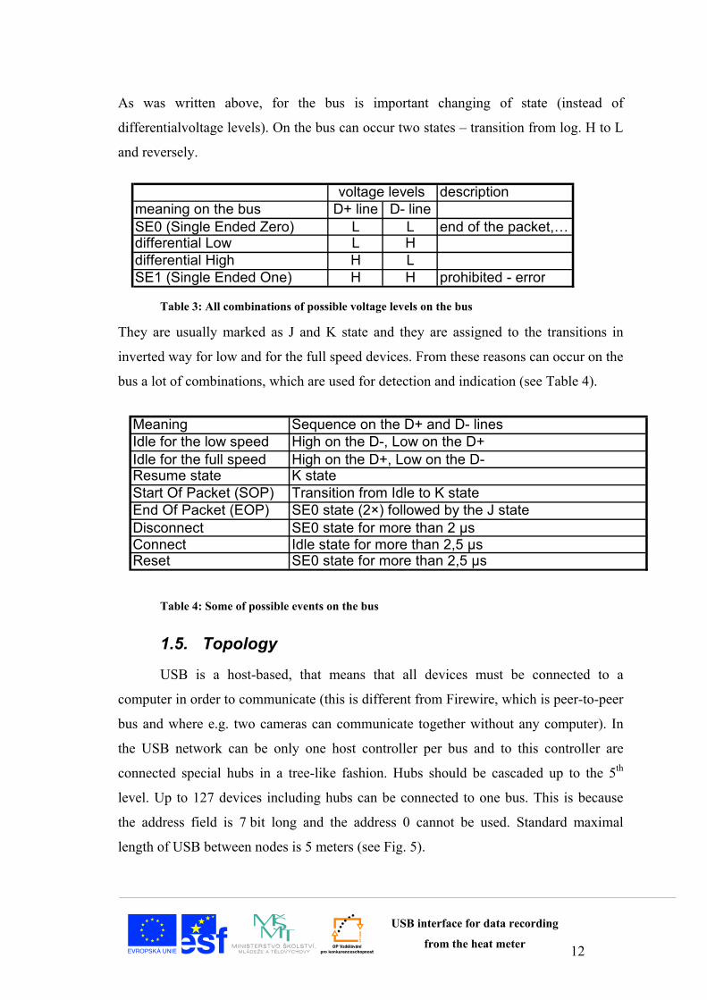
As was written above, for the bus is important changing of state (instead of
differentialvoltage levels). On the bus can occur two states – transition from log. H to L
and reversely.
voltage levels descriptionmeaning on the bus D+ line D- lineSE0 (Single Ended Zero) L L end of the packet,…differential Low L Hdifferential High H LSE1 (Single Ended One) H H prohibited - error
Table 3: All combinations of possible voltage levels on the bus
They are usually marked as J and K state and they are assigned to the transitions in
inverted way for low and for the full speed devices. From these reasons can occur on the
bus a lot of combinations, which are used for detection and indication (see Table 4).
Meaning Sequence on the D+ and D- linesIdle for the low speed High on the D-, Low on the D+Idle for the full speed High on the D+, Low on the D-Resume state K stateStart Of Packet (SOP) Transition from Idle to K stateEnd Of Packet (EOP) SE0 state (2×) followed by the J stateDisconnect SE0 state for more than 2 μsConnect Idle state for more than 2,5 μsReset SE0 state for more than 2,5 μs
Table 4: Some of possible events on the bus
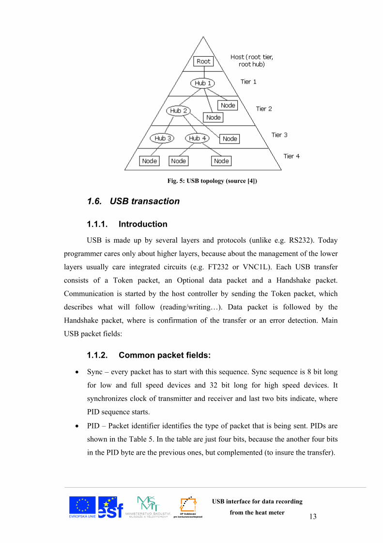
1.5. Topology
USB is a host-based, that means that all devices must be connected to a
computer in order to communicate (this is different from Firewire, which is peer-to-peer
bus and where e.g. two cameras can communicate together without any computer). In
the USB network can be only one host controller per bus and to this controller are
connected special hubs in a tree-like fashion. Hubs should be cascaded up to the 5th
level. Up to 127 devices including hubs can be connected to one bus. This is because
the address field is 7 bit long and the address 0 cannot be used. Standard maximal
length of USB between nodes is 5 meters (see Fig. 5).
13
USB interface for data recording
from the heat meter
Fig. 5: USB topology (source [4])
1.6. USB transaction
1.1.1. Introduction
USB is made up by several layers and protocols (unlike e.g. RS232). Today
programmer cares only about higher layers, because about the management of the lower
layers usually care integrated circuits (e.g. FT232 or VNC1L). Each USB transfer
consists of a Token packet, an Optional data packet and a Handshake packet.
Communication is started by the host controller by sending the Token packet, which
describes what will follow (reading/writing…). Data packet is followed by the
Handshake packet, where is confirmation of the transfer or an error detection. Main
USB packet fields:
1.1.2. Common packet fields:
Sync – every packet has to start with this sequence. Sync sequence is 8 bit long
for low and full speed devices and 32 bit long for high speed devices. It
synchronizes clock of transmitter and receiver and last two bits indicate, where
PID sequence starts.
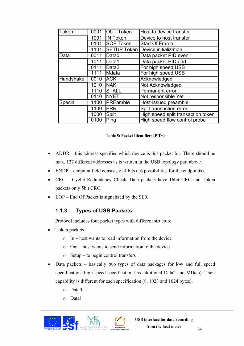
PID – Packet identifier identifies the type of packet that is being sent. PIDs are
shown in the Table 5. In the table are just four bits, because the another four bits
in the PID byte are the previous ones, but complemented (to insure the transfer).
14
USB interface for data recording
from the heat meter
Token 0001 OUT Token Host to device transfer1001 IN Token Device to host transfer0101 SOF Token Start Of Frame1101 SETUP Token Device initialization
Data 0011 Data0 Data packet PID even1011 Data1 Data packet PID odd0111 Data2 For high speed USB1111 Mdata For high speed USB
Handshake 0010 ACK Acknowledged1010 NAK Not Acknowledged1110 STALL Permanent error0110 NYET Not responsible Yet
Special 1100 PREamble Host-issued preamble1100 ERR Split transaction error1000 Split High speed split transaction token0100 Ping High speed flow control probe
Table 5: Packet Identifiers (PIDs)
ADDR – this address specifies which device is this packet for. There should be
max. 127 different addresses as is written in the USB topology part above.
ENDP – endpoint field consists of 4 bits (16 possibilities for the endpoints).
CRC – Cyclic Redundancy Check. Data packets have 16bit CRC and Token
packets only 5bit CRC.
EOP – End Of Packet is signalized by the SE0.
1.1.3. Types of USB Packets:
Protocol includes four packet types with different structure.
Token packets
o In – host wants to read information from the device
o Out – host wants to send information to the device
o Setup – to begin control transfers
Data packets – basically two types of data packages for low and full speed
specification (high speed specification has additional Data2 and MData). Their
capability is different for each specification (8, 1023 and 1024 bytes).
o Data0
o Data1
15
USB interface for data recording
from the heat meter
Handshake packets
o ACK – Acknowledgement (packet was successfully received).
o NAK – Informs, that device is not temporarily able to send or receive
data.
o STALL – Device is in state, which needs intervention by the host
controller.
SOF – Start of Frame Packet consists of 11bit frame number, which is sent by
the host controller every 1 ms ± 500 ns on the full speed bus and every
125 μs ± 0,0625 μs on the high speed bus.
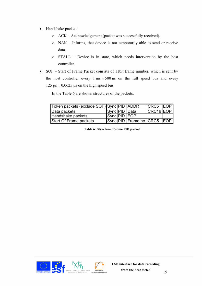
In the Table 6 are shown structures of the packets.
Token packets (exclude SOF) Sync PID ADDR CRC5 EOPData packets Sync PID Data CRC16 EOPHandshake packets Sync PID EOPStart Of Frame packets Sync PID Frame no. CRC5 EOP
Table 6: Structure of some PID packet
16
USB interface for data recording
from the heat meter
3. VDIP2 module
1.7. Introduction
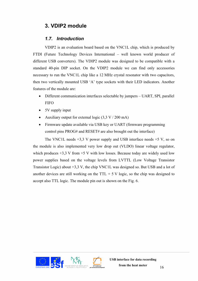
VDIP2 is an evaluation board based on the VNC1L chip, which is produced by
FTDI (Future Technology Devices International – well known world producer of
different USB converters). The VDIP2 module was designed to be compatible with a
standard 40-pin DIP socket. On the VDIP2 module we can find only accessories
necessary to run the VNC1L chip like a 12 MHz crystal resonator with two capacitors,
then two vertically mounted USB ‘A’ type sockets with their LED indicators. Another
features of the module are:
Different communication interfaces selectable by jumpers – UART, SPI, parallel
FIFO
5V supply input
Auxiliary output for external logic (3,3 V / 200 mA)
Firmware update available via USB key or UART (firmware programming
control pins PROG# and RESET# are also brought out the interface)
The VNC1L needs +3,3 V power supply and USB interface needs +5 V, so on
the module is also implemented very low drop out (VLDO) linear voltage regulator,
which produces +3,3 V from +5 V with low losses. Because today are widely used low
power supplies based on the voltage levels from LVTTL (Low Voltage Transistor
Transistor Logic) about +3,3 V, the chip VNC1L was designed so. But USB and a lot of
another devices are still working on the TTL + 5 V logic, so the chip was designed to
accept also TTL logic. The module pin out is shown on the Fig. 6.
17
USB interface for data recording
from the heat meter
Fig. 6: Assignment of the pins on the module (source [5])
1.8. Communication
In this part are described three different interfaces for communication
implemented in the VDIP2 module. One of the three interfaces has to be chosen by
jumpers as shown in the Table 1. For UART there are two possibilities, which means
that they are just inverted. These jumpers are used to pull up or down two pins (no.46
and 47) on the VNC1L chip.
I/O mode JUMPER3 JUMPER4
UART 1 - 2 1 - 2
SPI 2 - 3 1 - 2
FIFO 1 - 2 2 - 3
UART 2 - 3 2 - 3
Table 7: Possible jumper combinations to choose interface
1.1.4. UART
Classical RS232 interface (after voltage conversion) with full 9-pin serial port
For ordinary communication we need necessarily just 5 pins – RxD, TxD, GND
(RTS and CTS have to be pulled down to the ground through resistors)
LVTTL (3,3 V) voltage levels, but TTL (5 V) tolerant
Baud rate is settable from 300 till 1 MBd (after reset is always set to 9600 Bd)
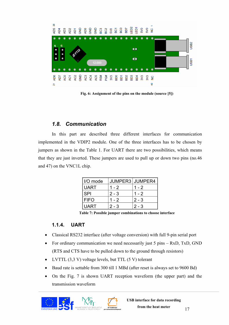
On the Fig. 7 is shown UART reception waveform (the upper part) and the
transmission waveform
18
USB interface for data recording
from the heat meter
Fig. 7: Sequences on the pins during reception and transmition of one byte (source [6])
1.1.5. SPI
Uses four pins four pins SCLK (Serial Clock), SDI (Serial Data Input), SDO
(Serial Data Output), CS (Chip Select)
can operate with the clock (SCLK) frequency up to 12 MHz
differs from other implementations, because it uses 13clock sequence to transfer
a single byte of data
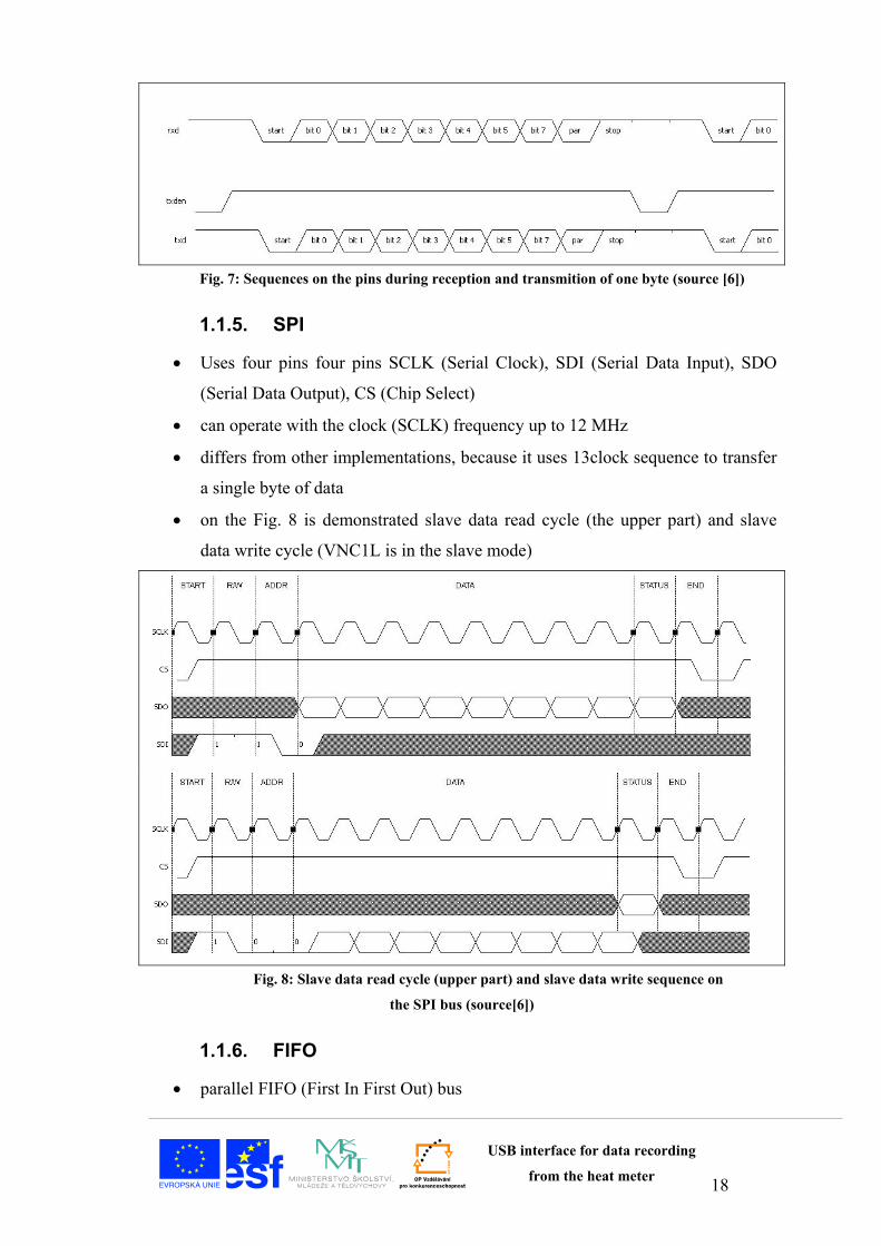
on the Fig. 8 is demonstrated slave data read cycle (the upper part) and slave
data write cycle (VNC1L is in the slave mode)
Fig. 8: Slave data read cycle (upper part) and slave data write sequence on
the SPI bus (source[6])
1.1.6. FIFO
parallel FIFO (First In First Out) bus
19
USB interface for data recording
from the heat meter
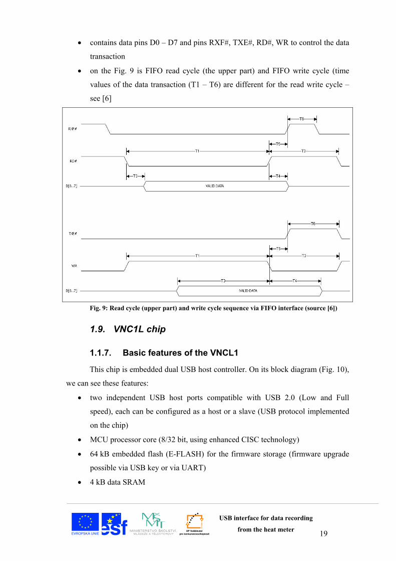
contains data pins D0 – D7 and pins RXF#, TXE#, RD#, WR to control the data
transaction
on the Fig. 9 is FIFO read cycle (the upper part) and FIFO write cycle (time
values of the data transaction (T1 – T6) are different for the read write cycle –
see [6]
Fig. 9: Read cycle (upper part) and write cycle sequence via FIFO interface (source [6])
1.9. VNC1L chip
1.1.7. Basic features of the VNCL1
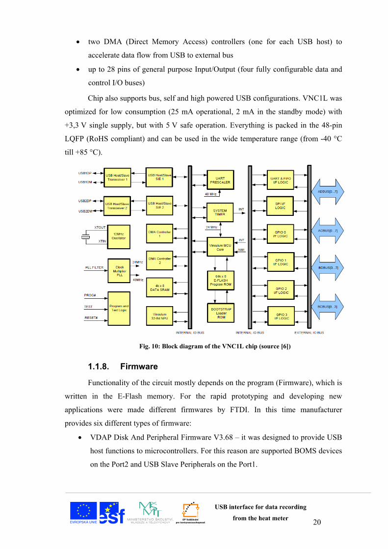
This chip is embedded dual USB host controller. On its block diagram (Fig. 10),
we can see these features:
two independent USB host ports compatible with USB 2.0 (Low and Full
speed), each can be configured as a host or a slave (USB protocol implemented
on the chip)
MCU processor core (8/32 bit, using enhanced CISC technology)
64 kB embedded flash (E-FLASH) for the firmware storage (firmware upgrade
possible via USB key or via UART)
4 kB data SRAM
20
USB interface for data recording
from the heat meter
two DMA (Direct Memory Access) controllers (one for each USB host) to
accelerate data flow from USB to external bus
up to 28 pins of general purpose Input/Output (four fully configurable data and
control I/O buses)
Chip also supports bus, self and high powered USB configurations. VNC1L was
optimized for low consumption (25 mA operational, 2 mA in the standby mode) with
+3,3 V single supply, but with 5 V safe operation. Everything is packed in the 48-pin
LQFP (RoHS compliant) and can be used in the wide temperature range (from -40 °C
till +85 °C).
Fig. 10: Block diagram of the VNC1L chip (source [6])
1.1.8. Firmware
Functionality of the circuit mostly depends on the program (Firmware), which is
written in the E-Flash memory. For the rapid prototyping and developing new
applications were made different firmwares by FTDI. In this time manufacturer
provides six different types of firmware:
VDAP Disk And Peripheral Firmware V3.68 – it was designed to provide USB
host functions to microcontrollers. For this reason are supported BOMS devices
on the Port2 and USB Slave Peripherals on the Port1.
21
USB interface for data recording
from the heat meter
VMSC Music Firmware (for VMUSIC modules) V3.68 – it is similar to the
VDAP, but new commands were added for playback through an MP3 decoder
chip (e.g. VLSI VS1003 MP3 decoder communicates via SPI with the
Vinculum, which has data from USB key, and Vinculum communicates with
the main processor through command monitor)
VDPS Disk or Peripheral Firmware V3.68 – provides connection with the
computer on the Port1. If the computer is connected, VNC1L enumerates as an
FT232B device and loads drivers. In this case it is necessary to use voltage
divider to synchronize the voltage from the computer to the Vinculum.
VCDC Communication Device Class Firmware – was developed primary to
provide modem-like functionality to microcontrollers. Communication Device
Class (CDC) must support sub-class of Abstract Control Model and have
compatible bulk endpoints.
VDIF Disk Interface Firmware – it works like VDAP until FTDI peripheral
(suitable are FT232B, FT232R and FT2232) is detected on the USB Port1. Then
command monitor stops communication via standard pins and becomes active
on the USB Port1 with the same baud rate like on the serial UART interface.
VDFC Disk File Copy Firmware – supports Bulk Only Mass Storage (BOMS)
on the both Ports. Then is possible to manipulate with data from one BOMS to
another one.
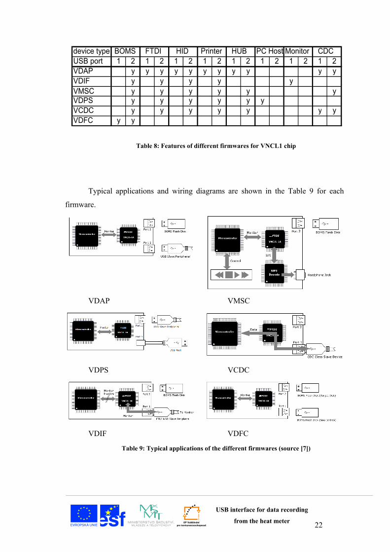
In the Table 8 is shown the functionality for each firmware for each USB port
(CDC Communication Device Class, BOMS Bulk Only Mass Storage, HID Human
Input Device FTDI means another FTDI peripherals, monitor means the access to the
command monitor, which accepts commands). The chip supports only these devices and
then it is also constrained by specification of the USB 2.0, which is supported – precised
description of these devices is in the firmware datasheet [7] in the chapter 9.2. Some
problems should be solved by connecting devices via HUB, because HUB is usually
supported except the VDIF firmware (see Table 8).
22
USB interface for data recording
from the heat meter
device type BOMS FTDI HID Printer HUB PC Host Monitor CDCUSB port 1 2 1 2 1 2 1 2 1 2 1 2 1 2 1 2VDAP y y y y y y y y y y yVDIF y y y y yVMSC y y y y y yVDPS y y y y y yVCDC y y y y y y yVDFC y y
Table 8: Features of different firmwares for VNCL1 chip
Typical applications and wiring diagrams are shown in the Table 9 for each
firmware.
VDAP VMSC
VDPS VCDC
VDIF VDFC
Table 9: Typical applications of the different firmwares (source [7])
23
USB interface for data recording
from the heat meter
1.1.9. Upgrading firmware
Firmware should be upgraded in the two different ways. One possibility is to use
VPROG programmer (ROM programmer), which communicates via serial port with the
VNCL1. During programming using this method has to be PROG pin pulled down to
activate a special mode for the FlashROM upgrading. Second choice is to use an USB
key. In the root directory has to be the firmware file named ‘FTRFB.FTD’. After
connecting USB key is necessary to reset the module, then the file is automatically
detected and firmware after few seconds upgraded.
4. Heat meter
1.10. General description
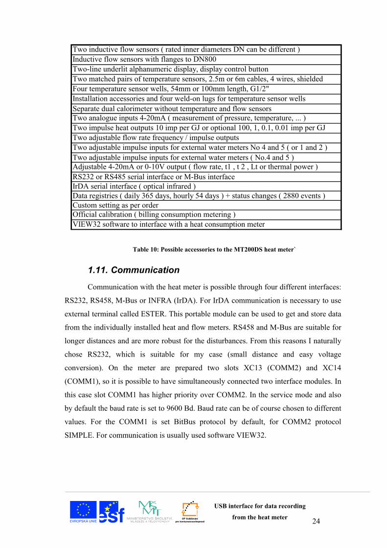
MT200 is designed for measurements in heating and residual applications, but it
can be used for measurements of the cooling water consumption as well. For the flow
sensing are used inductive flow sensors. These sensors do not contain any mechanical
accessories (no moving parts and no orifice plates) placed inside the piping, so they do
not cause any pressure losses. Despite this they have still good accuracy (from the
specification for the heat consumption meter’s flow sensors are placed in the second
class pursuant to EN 1434, Δθmin = 2 °C). In the Table 10 are shown all accessories,
which can be added and combined according to the customer’s requirements.
24
USB interface for data recording
from the heat meter
Two inductive flow sensors ( rated inner diameters DN can be different )Inductive flow sensors with flanges to DN800Two-line underlit alphanumeric display, display control buttonTwo matched pairs of temperature sensors, 2.5m or 6m cables, 4 wires, shieldedFour temperature sensor wells, 54mm or 100mm length, G1/2"Installation accessories and four weld-on lugs for temperature sensor wellsSeparate dual calorimeter without temperature and flow sensorsTwo analogue inputs 4-20mA ( measurement of pressure, temperature, ... )Two impulse heat outputs 10 imp per GJ or optional 100, 1, 0.1, 0.01 imp per GJTwo adjustable flow rate frequency / impulse outputsTwo adjustable impulse inputs for external water meters No 4 and 5 ( or 1 and 2 )Two adjustable impulse inputs for external water meters ( No.4 and 5 )Adjustable 4-20mA or 0-10V output ( flow rate, t1 , t 2 , Lt or thermal power )RS232 or RS485 serial interface or M-Bus interfaceIrDA serial interface ( optical infrared )Data registries ( daily 365 days, hourly 54 days ) + status changes ( 2880 events )Custom setting as per orderOfficial calibration ( billing consumption metering )VIEW32 software to interface with a heat consumption meter
Table 10: Possible accessories to the MT200DS heat meter`
1.11. Communication
Communication with the heat meter is possible through four different interfaces:
RS232, RS458, M-Bus or INFRA (IrDA). For IrDA communication is necessary to use
external terminal called ESTER. This portable module can be used to get and store data
from the individually installed heat and flow meters. RS458 and M-Bus are suitable for
longer distances and are more robust for the disturbances. From this reasons I naturally
chose RS232, which is suitable for my case (small distance and easy voltage
conversion). On the meter are prepared two slots XC13 (COMM2) and XC14
(COMM1), so it is possible to have simultaneously connected two interface modules. In
this case slot COMM1 has higher priority over COMM2. In the service mode and also
by default the baud rate is set to 9600 Bd. Baud rate can be of course chosen to different
values. For the COMM1 is set BitBus protocol by default, for COMM2 protocol
SIMPLE. For communication is usually used software VIEW32.
25
USB interface for data recording
from the heat meter
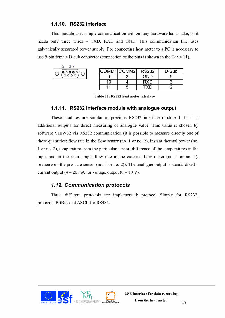
1.1.10. RS232 interface
This module uses simple communication without any hardware handshake, so it
needs only three wires – TXD, RXD and GND. This communication line uses
galvanically separated power supply. For connecting heat meter to a PC is necessary to
use 9-pin female D-sub connector (connection of the pins is shown in the Table 11).
COMM1 COMM2 RS232 D-Sub9 3 GND 5
10 4 RXD 311 5 TXD 2
Table 11: RS232 heat meter interface
1.1.11. RS232 interface module with analogue output
These modules are similar to previous RS232 interface module, but it has
additional outputs for direct measuring of analogue value. This value is chosen by
software VIEW32 via RS232 communication (it is possible to measure directly one of
these quantities: flow rate in the flow sensor (no. 1 or no. 2), instant thermal power (no.
1 or no. 2), temperature from the particular sensor, difference of the temperatures in the
input and in the return pipe, flow rate in the external flow meter (no. 4 or no. 5),
pressure on the pressure sensor (no. 1 or no. 2)). The analogue output is standardized –
current output (4 – 20 mA) or voltage output (0 – 10 V).
1.12. Communication protocols
Three different protocols are implemented: protocol Simple for RS232,
protocols BitBus and ASCII for RS485.
26
USB interface for data recording
from the heat meter
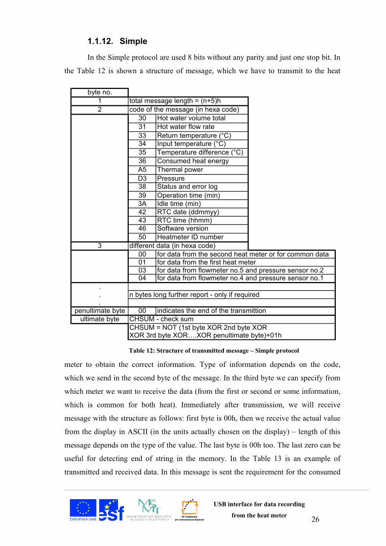
1.1.12. Simple
In the Simple protocol are used 8 bits without any parity and just one stop bit. In
the Table 12 is shown a structure of message, which we have to transmit to the heat
byte no.1 total message length = (n+5)h2 code of the message (in hexa code)
30 Hot water volume total31 Hot water flow rate33 Return temperature (°C)34 Input temperature (°C)35 Temperature difference (°C)36 Consumed heat energyA5 Thermal powerD3 Pressure38 Status and error log39 Operation time (min)3A Idle time (min)42 RTC date (ddmmyy)43 RTC time (hhmm)46 Software version50 Heatmeter ID number
3 different data (in hexa code)00 for data from the second heat meter or for common data01 for data from the first heat meter03 for data from flowmeter no.5 and pressure sensor no.204 for data from flowmeter no.4 and pressure sensor no.1
.
. n bytes long further report - only if required
.penultimate byte 00 indicates the end of the transmittion
ultimate byte CHSUM - check sumCHSUM = NOT (1st byte XOR 2nd byte XOR XOR 3rd byte XOR….XOR penultimate byte)+01h
Table 12: Structure of transmitted message – Simple protocol
meter to obtain the correct information. Type of information depends on the code,
which we send in the second byte of the message. In the third byte we can specify from
which meter we want to receive the data (from the first or second or some information,
which is common for both heat). Immediately after transmission, we will receive
message with the structure as follows: first byte is 00h, then we receive the actual value
from the display in ASCII (in the units actually chosen on the display) – length of this
message depends on the type of the value. The last byte is 00h too. The last zero can be
useful for detecting end of string in the memory. In the Table 13 is an example of
transmitted and received data. In this message is sent the requirement for the consumed
27
USB interface for data recording
from the heat meter
heat energy (second byte is 36h) from the first heat meter (third byte is 01h). Received
message is simple code between first and the last zero.
transmitted data in hexa code: 05 36 01 00 CEreceived data in hexa code: 00 31 32 33 2E 34 35 36 37 00received message translated to ascii: 123.4567
Table 13: An example of data transaction via RS232
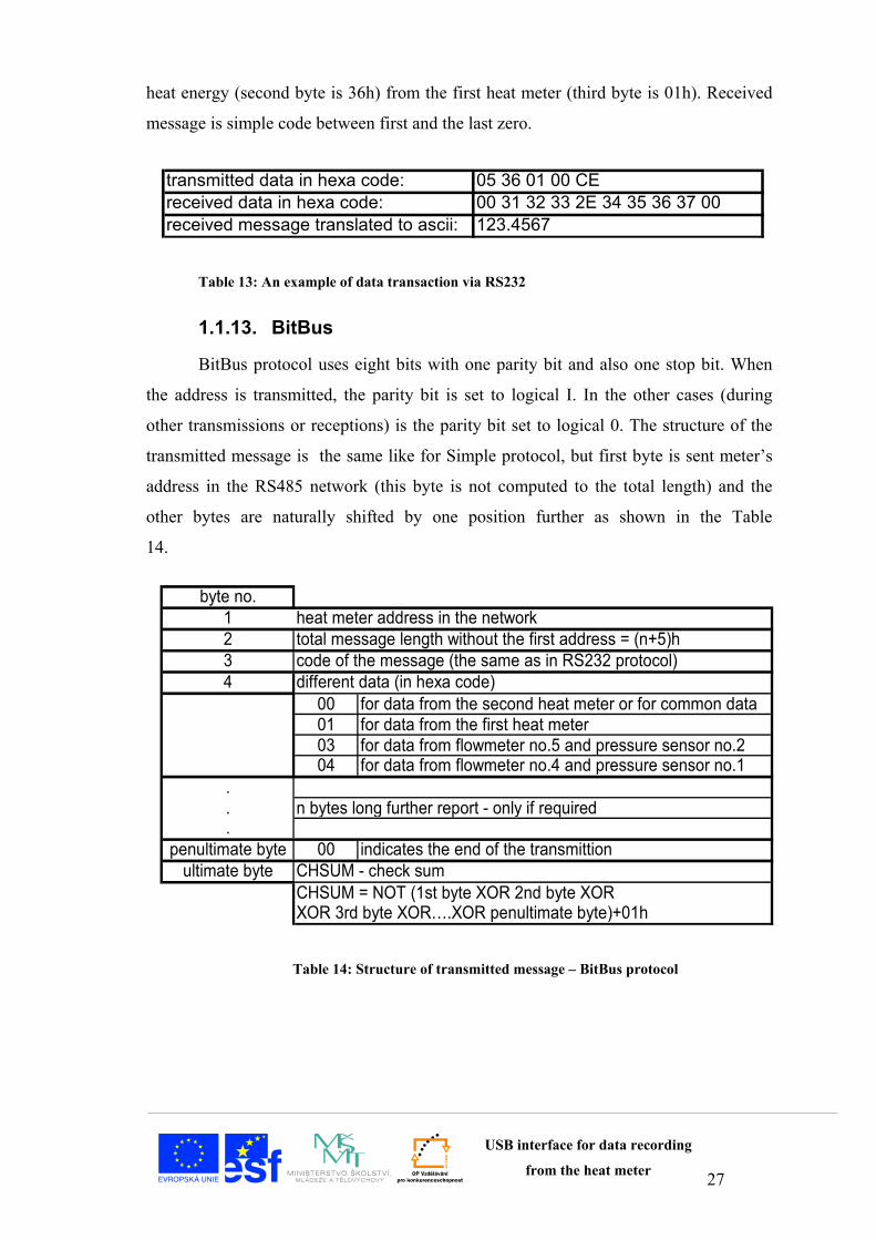
1.1.13. BitBus
BitBus protocol uses eight bits with one parity bit and also one stop bit. When
the address is transmitted, the parity bit is set to logical I. In the other cases (during
other transmissions or receptions) is the parity bit set to logical 0. The structure of the
transmitted message is the same like for Simple protocol, but first byte is sent meter’s
address in the RS485 network (this byte is not computed to the total length) and the
other bytes are naturally shifted by one position further as shown in the Table
14.
byte no.1 heat meter address in the network2 total message length without the first address = (n+5)h3 code of the message (the same as in RS232 protocol)4 different data (in hexa code)
00 for data from the second heat meter or for common data01 for data from the first heat meter03 for data from flowmeter no.5 and pressure sensor no.204 for data from flowmeter no.4 and pressure sensor no.1
.
. n bytes long further report - only if required
.penultimate byte 00 indicates the end of the transmittion
ultimate byte CHSUM - check sumCHSUM = NOT (1st byte XOR 2nd byte XOR XOR 3rd byte XOR….XOR penultimate byte)+01h
Table 14: Structure of transmitted message – BitBus protocol
28
USB interface for data recording
from the heat meter
transmitted data in hexa code: 0 F 0 5 3 6 0 0 0 0 C Dreceived data in hexa code: 0 F 0 C 0 0 3 1 3 2 3 3 2 E 3 4 3 5 3 6 3 7 0 0 E Ereceived message in ascii code: 123.4567
Table 15: An example of data transaction via RS485
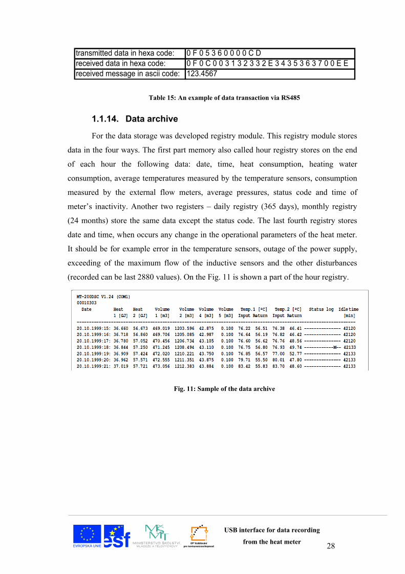
1.1.14. Data archive
For the data storage was developed registry module. This registry module stores
data in the four ways. The first part memory also called hour registry stores on the end
of each hour the following data: date, time, heat consumption, heating water
consumption, average temperatures measured by the temperature sensors, consumption
measured by the external flow meters, average pressures, status code and time of
meter’s inactivity. Another two registers – daily registry (365 days), monthly registry
(24 months) store the same data except the status code. The last fourth registry stores
date and time, when occurs any change in the operational parameters of the heat meter.
It should be for example error in the temperature sensors, outage of the power supply,
exceeding of the maximum flow of the inductive sensors and the other disturbances
(recorded can be last 2880 values). On the Fig. 11 is shown a part of the hour registry.
Fig. 11: Sample of the data archive
29
USB interface for data recording
from the heat meter
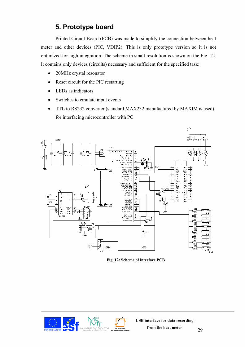
5. Prototype board
Printed Circuit Board (PCB) was made to simplify the connection between heat
meter and other devices (PIC, VDIP2). This is only prototype version so it is not
optimized for high integration. The scheme in small resolution is shown on the Fig. 12.
It contains only devices (circuits) necessary and sufficient for the specified task:
20MHz crystal resonator
Reset circuit for the PIC restarting
LEDs as indicators
Switches to emulate input events
TTL to RS232 converter (standard MAX232 manufactured by MAXIM is used)
for interfacing microcontroller with PC
Fig. 12: Scheme of interface PCB
30
USB interface for data recording
from the heat meter
6. Software
1.13. Description of used software tools
For coding I used MPLAB IDE with C18 compiler. This software is provided
and fully supported by Microchip. Microchip also provides a lot of libraries for PIC18
series. To upload the program to the microcontroller it is necessary to use some standard
or ICSP (In-Circuit Serial Programming) programmer. Another possibility is to use
some Bootloader. Bootloader is a special program, which is able to communicate with
computer via RS232 and to store the received data into its flash program memory. This
was not possible few years ago, because microcontrollers were not able to rewrite their
own program memory. This advantage should be sometimes disadvantage, when human
does not care about the part of the memory, which is prohibited to use. Bootloader
usually needs few instructions on the very beginning of the program memory to make a
jump to the total end of the program memory, where is situated the bigger part of the
bootloader (RS232 configuration and communication protocol). Then the user’s
program can be situated everywhere except these memory parts. On the internet is
possible to find and download many different bootloaders. Very famous are Tiny
bootloaders, which are the smallest (occupy only 100 words of the program memory).
This is, because they make just necessary communication, and the control management
is done by the computer. In this application I used TruTrack bootloader. Although it is
bigger than Tiny bootloader, the software interface is very simple and reliably.
31
USB interface for data recording
from the heat meter
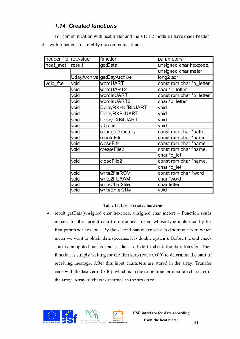
1.14. Created functions
For communication with heat meter and the VDIP2 module I have made header
files with functions to simplify the communication.
header file ret.value function parametersheat_met result getData unsigned char hexcode,
unsigned char meterUdayArchive getDayArchive long2 adr
vdip_fce void wordUART const rom char *p_lettervoid wordUART2 char *p_lettervoid wordlnUART const rom char *p_lettervoid wordlnUART2 char *p_lettervoid DelayRXHalfBitUART voidvoid DelayRXBitUART voidvoid DelayTXBitUART voidvoid vdipInit voidvoid changeDirectory const rom char *pathvoid createFile const rom char *namevoid closeFile const rom char *namevoid createFile2 const rom char *name,
char *p_letvoid closeFile2 const rom char *name,
char *p_letvoid write2fileROM const rom char *wordvoid write2fileRAM char *wordvoid writeChar2file char lettervoid writeEnter2file void
Table 16: List of created functions
result getData(unsigned char hexcode, unsigned char meter) – Function sends
request for the current data from the heat meter, whose type is defined by the
first parameter hexcode. By the second parameter we can determine from which
meter we want to obtain data (because it is double system). Before the end check
sum is computed and is sent as the last byte to check the data transfer. Then
function is simply waiting for the first zero (code 0x00) to determine the start of
receiving message. After this input characters are stored in the array. Transfer
ends with the last zero (0x00), which is in the same time termination character in
the array. Array of chars is returned in the structure.
32
USB interface for data recording
from the heat meter
void wordUART(const rom char *p_letter) – function sends string of data
characters situated in a program memory and terminated by 0x00 to the UART
(Universal Asynchronous Receiver/Transmitter).
void wordUART2(char *p_letter) – equivalent to the wordUART function, but
string is now situated in the data RAM memory
void wordlnUART(const rom char *p_letter), void wordlnUART2(char
*p_letter) these functions are equivalents to the previous ones, just they send
on the end of the communication carriage return character to finish the line
void DelayRXHalfBitUART(), void DelayRXBitUART(), void
DelayTXBitUART() are delay loops (252, 507 and 521 instruction cycles),
which are used during the serial communication transfer
void vdipInit() – function to initialize Vinculum. At first is written command
‘IPA’ to switch on the ASCII mode of the monitor, then it is command ‘ECS’ to
use extended command set
void changeDirectory(const rom char *path) – switches actual directory on the
USB key to the one defined by the path from program memory
void createFile(const rom char *name) – opens file for writing. If the file does
not exist, it creates this file.
void closeFile(const rom char *name) – closes currently opened file
void createFile2(const rom char *name,char *p_let), void closeFile2(const rom
char *name, char *p_let) – equivalents to the functions above, but the part of the
filename is stored in the RAM (after it is used to make name of the file with
actual time)
void write2fileROM(const rom char *word) – writes string from the program
memory to the currently opened file for write
void write2fileRAM(char *word) – writes string from the data RAM to the
currently opened file for write
void writeChar2file(char letter) – writes single character to the file
void writeEnter2file() – writes feed line and carriage return characters to go to a
new line
33
USB interface for data recording
from the heat meter
1.15. Main program
Program starts with initialization of the input and output ports and serial ports.
For this task was necessary to create one extra software serial port. First (the hardware
one) is situated on the PORTC and is used to communicate with the heat meter. Second
UART (the software one) communicates with the VDIP2 module. Baud rate of the first
port is set to the maximal speed for the heat meter (i.e. 38 400 Bd). After this is VDIP2
initialized for the communication (vdipInit function). Communication, which follows,
has simple structure easy to understand from the source code.
7. Conclusion
On the beginning I studied USB communication, which is more sophisticated
compared to RS232 communication. USB interface provides more comfort for the end
user (a lot of management is done automatically), but this makes USB much more
complicated for developers. To know how does it really work I tried to catch
communication with the USB key by software in the PC. Then I was able to recognize
data packages. As a software I tried Device Monitoring Studio (only trial version for
free). Fortunately in these days is not necessary and it is also ineffective to manage USB
communication on the low layers by hand. After USB communication I tried to
communicate with the VDIP2 module. I tried to connect some HIDs, but I found, that it
does not work with a lot of them, because VNC1L does not support low speed devices.
It is difficult task to get data sheet of the HID before you buy it to know whether it is
supported or not. I had to have a look on the chip inside the device to see which type of
speed supports. I tried to communicate with VNCL1 at first directly with the computer
via Terminal (using RS232 mode). Then after some experiments I switched to direct
communication between VDIP2 and microcontroller. Because VNC1L thanks to
precisely made firmware provides a lot of commands for BOMS management, it was
not so difficult to create a file with .csv extension. I chose this format (.csv), because it
is simple to create (data are substracted by comma) and it is simple to use – it can be
opened by Excel to make statistics or graphs.
Next task was to manage communication with the heat meter. At first I tried it
also via Hyperterminal, but it was not so difficult thanks to precise description in the
data sheets. Because PIC18f452 contains only one hardware serial port and I needed
two of them, I decided to use hardware one for the heat meter communication and to
34
USB interface for data recording
from the heat meter
create new software serial port for the VDIP2 module. On the software one is baud rate
set to standard 9600 Bdand on the hardware one to the highest possible (for the heat
meter) – 38400 Bd.
After these experiments I made a scheme and PCB in the Eagle layout editor.
I realized it and checked the communication. The interface works like follows: after
USB key is detected on the Port2, LED2 lights. Now when the button on the PORTB7
is pushed, communication starts – firstly data are obtained from the heat meter and
stored in an array. Then in the directory DATA on the USB key is created file with
actual time and data from the array.
The communication works fine, but sometimes when some unexpected error
occurs, it can fail. To get rid of this is necessary to detect errors, make some additional
control algorithms (parity, check sum...) – make the communication more robust. The
next task for future development should be to realize interface with devices in smaller
(SMD) packages and everything minimize (make a small module connectable to
standard slots on the heat meter).
35
USB interface for data recording
from the heat meter
Literature
[1] USB connector pinout [online]. 20.5.2010.
URL:<http://pinouts.ru/Slots/USB_pinout.shtml>
[2] Komunikační protokol univerzální sériové sběrnice [online]. 20.5.2010.
URL: <http://www.root.cz/clanky/komunikacni-protokol-universalni-seriove-
sbernice/#k02>
[3] USB in Nutshell [online]. 20.5.2010.
URL: <http://www.beyondlogic.org/usbnutshell/>
[4] Topology [online]. 20.5.2010.
URL:<http://i.technet.microsoft.com/Cc768200.wrkff01(en-us,TechNet.10).gif>
[5] VDIP2 Vinculum VNC1L Prototyping Module [online]. 20.5.2010.
URL: <http://www.vinculum.com/documents/datasheets/DS_VDIP2.pdf>
[6] Vinculum VNC1L Embedded USB Host Controller IC Datasheet [online].
20.5.2010.URL: <http://www.vinculum.com/documents/datasheets/DS_VNC1L_V
201(FT_000030).pdf>
[7] Vinculum Firmware User Manual [online]. 20.5.2010.
URL: <http://www.vinculum.com/documents/fwspecs/UM_VinculumFirmware_V
205.pdf>
[8] MT200DS – Communicatio Protocols for Data Acquision [online]. 20.5.2010.
URL: < http://www.eesa.cz/documents/en/protocol/MT200DS_kom_e.pdf>
[9] MT200DS – Installation and Operation Manual [online]. 20.5.2010.
URL: <http://www.eesa.cz/documents/en/MT200DS_mtpa.pdf>
36
USB interface for data recording
from the heat meter
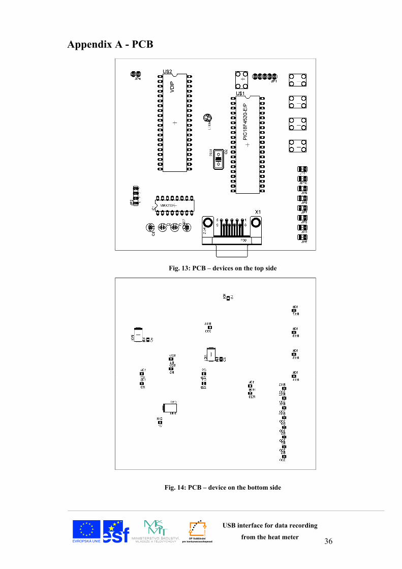
Appendix A - PCB
Fig. 13: PCB – devices on the top side
Fig. 14: PCB – device on the bottom side
37
USB interface for data recording
from the heat meter
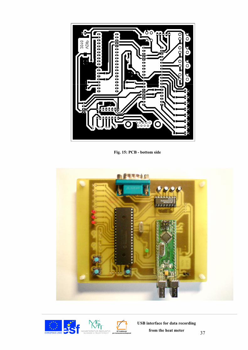
Fig. 15: PCB - bottom side
38
USB interface for data recording
from the heat meter
Fig. 16: Realized board - top view
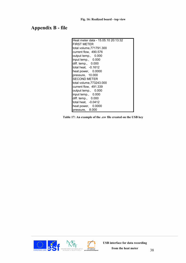
Appendix B - file
Heat meter data - 15.05.10 20:13:32FIRST METER total volume,771791.300current flow, 490.576output temp., 0.000input temp., 0.000diff. temp., 0.000total heat, -0.1612heat power, 0.0000pressure, 10.000SECOND METER total volume,773243.000current flow, 491.339output temp., 0.000input temp., 0.000diff. temp., 0.000total heat, -0.0412heat power, 0.0000pressure, 8.000
Table 17: An example of the .csv file created on the USB key