Embed Size (px)
Citation preview

Republic of Ireland Branch Structures and Construction
TOM MCCORMACK MEMORIAL
LECTURE Walton Theatre, Arts Building Trinity College
The Design and Construction of Taney Bridge, Dundrum Joe O’Donovan BE CEng FIEI MICE MConsEI Managing Director, Roughan & O’Donovan Ltd Keith Wilson MA CEng MICE Chief Bridge Engineer, Roughan & O’Donovan Ltd Tony Dempsey BA BAI PhD Associate, Roughan & O’Donovan Ltd
21st January 2003

ABSTRACT This paper describes the development, design and construction of Taney Bridge, an elegant, slender, prestressed concrete cable-stayed bridge constructed across one of the busiest road intersections in south Dublin. The development of the detailed design is discussed and some of the critical issues highlighted. The construction methods and controls are described with particular emphasis on the lessons to be learnt from this project.
2

INTRODUCTION Line B of the Dublin Light Rail Transit system (Luas) runs from St. Stephen’s Green to Sandyford Industrial Estate. For much of its route it follows the formation of the old Harcourt St. line which was abandoned in the late fifties. The original line crossed Dundrum Road at its junction with Taney Road just to the north of Dundrum village on a steel girder bridge which was demolished after the railway was abandoned, Figure 1. During the following years the junction was widened and became one of the most strategically important road intersections in south Dublin.
Figure 1 Taney Road Bridge circa. 1959
In 1997 preliminary planning for Luas was underway and Dun Laoghaire-Rathdown County Council (DLRCC) was developing plans for a bypass of Dundrum which would tie into the existing road network at Taney Cross. Roughan & O’Donovan Ltd was appointed under separate agreements to undertake the preliminary design for Luas of a bridge over Taney Cross and by DLRCC to design the Dundrum bypass. The railway crosses the line of Taney Road at a skew of 25°. To the north of the junction the light railway runs on the existing embankment. However, it would be necessary to raise the railway alignment to provide sufficient headroom over the junction. In order to keep the railway alignment (and hence cost) as low as possible it was necessary to consider bridge options with a shallow construction depth, e.g. cable-stayed, tied arch or through girder bridges. Preliminary bridge designs were developed in which the proposed support locations were chosen to be compatible with both the existing road layout and that of the new Dundrum bypass. The strategic importance of the junction within the road network of south Dublin required a bridge which could be
3
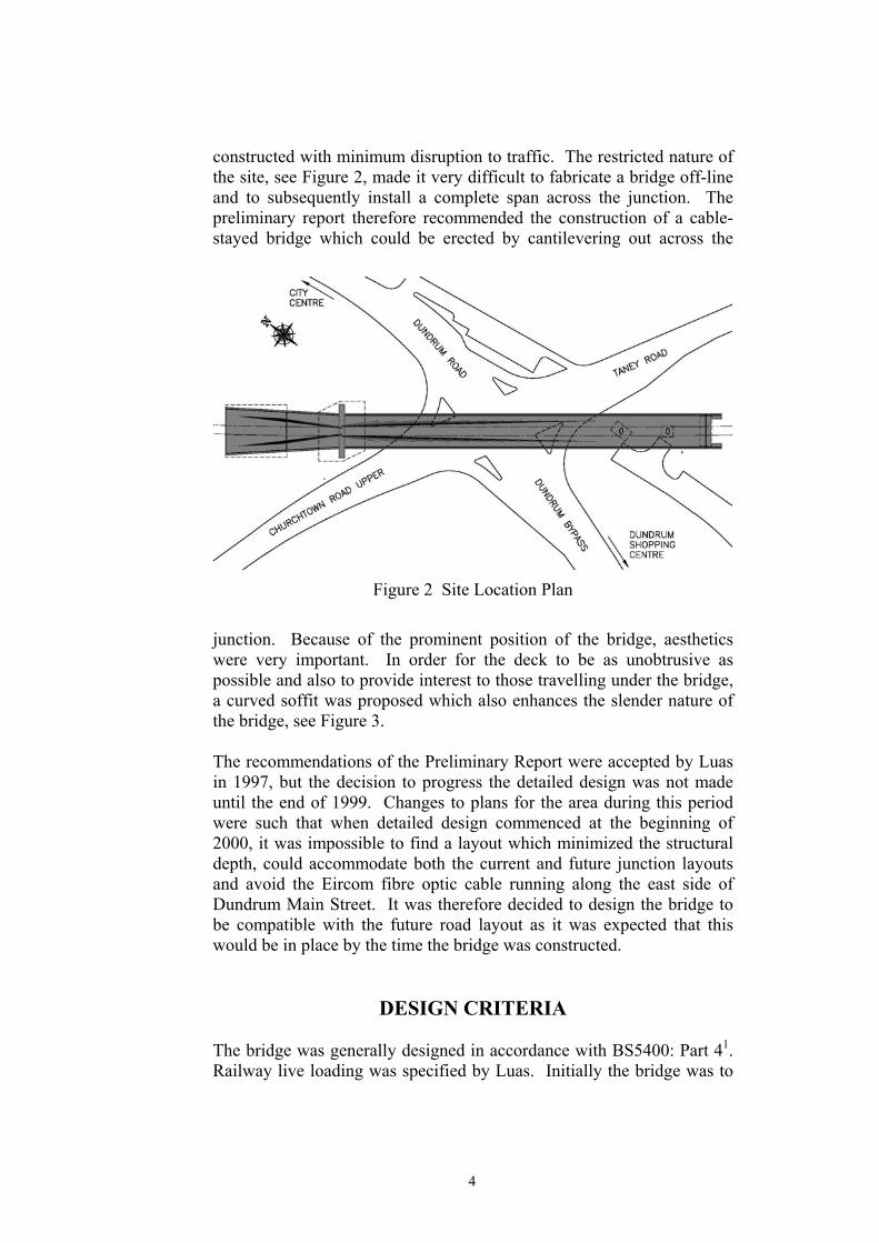
constructed with minimum disruption to traffic. The restricted nature of the site, see Figure 2, made it very difficult to fabricate a bridge off-line and to subsequently install a complete span across the junction. The preliminary report therefore recommended the construction of a cable-stayed bridge which could be erected by cantilevering out across the
Figure 2 Site Location Plan
junction. Because of the prominent position of the bridge, aesthetics were very important. In order for the deck to be as unobtrusive as possible and also to provide interest to those travelling under the bridge, a curved soffit was proposed which also enhances the slender nature of the bridge, see Figure 3. The recommendations of the Preliminary Report were accepted by Luas in 1997, but the decision to progress the detailed design was not made until the end of 1999. Changes to plans for the area during this period were such that when detailed design commenced at the beginning of 2000, it was impossible to find a layout which minimized the structural depth, could accommodate both the current and future junction layouts and avoid the Eircom fibre optic cable running along the east side of Dundrum Main Street. It was therefore decided to design the bridge to be compatible with the future road layout as it was expected that this would be in place by the time the bridge was constructed.
DESIGN CRITERIA The bridge was generally designed in accordance with BS5400: Part 41. Railway live loading was specified by Luas. Initially the bridge was to
4

be designed to carry loading appropriate to a light railway and a uniformly distributed load of 20 kN/m per track was specified, which was to be increased by a dynamic magnification factor of 1.5. This was later increased to 25 kN/m per track when it became apparent that the line might eventually be upgraded to a metro. It was also necessary to check that the cross-sectional layout of the bridge respected the structural gauge for both light rail and metro systems.
Figure 3 Artist’s Impression of Taney Bridge
There are a number of design aspects of cable-stayed bridges which are not covered by BS5400. These include the treatment of the preload in the stays at the ultimate limit state, differential temperature between the stays and the deck and pylon, cable-out scenarios, and vibration. Drawing on international experience, Roughan and O’Donovan developed appropriate design criteria for these aspects and these are summarised in the Appendix.
DEVELOPMENT OF DESIGN General Taney Bridge is an asymmetrical cable-stayed bridge with spans of 21.5, 108.5, 18.0 and 14.0 m and a slim, elegantly curved prestressed concrete deck only 1.325 m deep, see Figure 4. The deck is supported from a 50 m high insitu reinforced concrete pylon by 13 pairs of high tensile steel cables. Each cable consists of between 16 and 37 No. 15.7 mm diameter 7-wire strands.
5
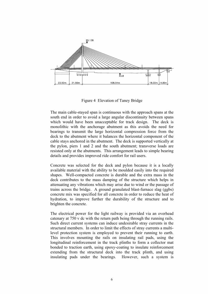
Figure 4 Elevation of Taney Bridge
The main cable-stayed span is continuous with the approach spans at the south end in order to avoid a large angular discontinuity between spans which would have been unacceptable for track design. The deck is monolithic with the anchorage abutment as this avoids the need for bearings to transmit the large horizontal compression force from the deck to the abutment where it balances the horizontal component of the cable stays anchored in the abutment. The deck is supported vertically at the pylon, piers 1 and 2 and the south abutment; transverse loads are resisted only at the abutments. This arrangement leads to simple bearing details and provides improved ride comfort for rail users. Concrete was selected for the deck and pylon because it is a locally available material with the ability to be moulded easily into the required shapes. Well-compacted concrete is durable and the extra mass in the deck contributes to the mass damping of the structure which helps in attenuating any vibrations which may arise due to wind or the passage of trains across the bridge. A ground granulated blast-furnace slag (ggbs) concrete mix was specified for all concrete in order to reduce the heat of hydration, to improve further the durability of the structure and to brighten the concrete. The electrical power for the light railway is provided via an overhead catenary at 750 v dc with the return path being through the running rails. Such direct current systems can induce undesirable stray currents in the structural members. In order to limit the effects of stray currents a multi-level protection system is employed to prevent their running to earth. This involves mounting the rails on insulating rail pads, using the longitudinal reinforcement in the track plinths to form a collector mat bonded to traction earth, using epoxy-coating to insulate reinforcement extending from the structural deck into the track plinth, and using insulating pads under the bearings. However, such a system is
6
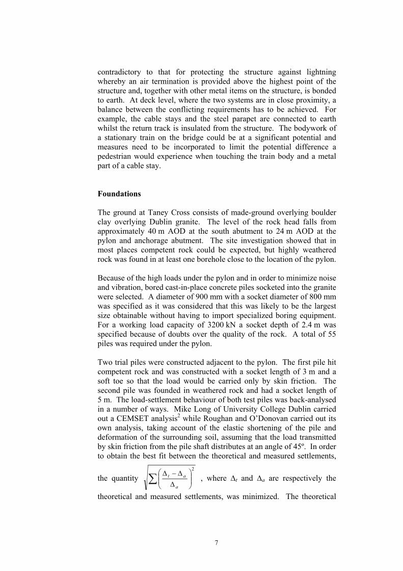
contradictory to that for protecting the structure against lightning whereby an air termination is provided above the highest point of the structure and, together with other metal items on the structure, is bonded to earth. At deck level, where the two systems are in close proximity, a balance between the conflicting requirements has to be achieved. For example, the cable stays and the steel parapet are connected to earth whilst the return track is insulated from the structure. The bodywork of a stationary train on the bridge could be at a significant potential and measures need to be incorporated to limit the potential difference a pedestrian would experience when touching the train body and a metal part of a cable stay. Foundations The ground at Taney Cross consists of made-ground overlying boulder clay overlying Dublin granite. The level of the rock head falls from approximately 40 m AOD at the south abutment to 24 m AOD at the pylon and anchorage abutment. The site investigation showed that in most places competent rock could be expected, but highly weathered rock was found in at least one borehole close to the location of the pylon. Because of the high loads under the pylon and in order to minimize noise and vibration, bored cast-in-place concrete piles socketed into the granite were selected. A diameter of 900 mm with a socket diameter of 800 mm was specified as it was considered that this was likely to be the largest size obtainable without having to import specialized boring equipment. For a working load capacity of 3200 kN a socket depth of 2.4 m was specified because of doubts over the quality of the rock. A total of 55 piles was required under the pylon. Two trial piles were constructed adjacent to the pylon. The first pile hit competent rock and was constructed with a socket length of 3 m and a soft toe so that the load would be carried only by skin friction. The second pile was founded in weathered rock and had a socket length of 5 m. The load-settlement behaviour of both test piles was back-analysed in a number of ways. Mike Long of University College Dublin carried out a CEMSET analysis2 while Roughan and O’Donovan carried out its own analysis, taking account of the elastic shortening of the pile and deformation of the surrounding soil, assuming that the load transmitted by skin friction from the pile shaft distributes at an angle of 45º. In order to obtain the best fit between the theoretical and measured settlements,
the quantity ∑
∆
∆−∆2
a
at , where ∆t and ∆a are respectively the
theoretical and measured settlements, was minimized. The theoretical
7
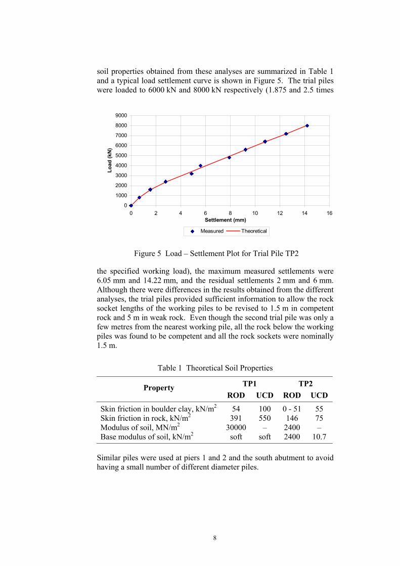
soil properties obtained from these analyses are summarized in Table 1 and a typical load settlement curve is shown in Figure 5. The trial piles were loaded to 6000 kN and 8000 kN respectively (1.875 and 2.5 times
the specified working load), the maximum measured settlements were 6.05 mm and 14.22 mm, and the residual settlements 2 mm and 6 mm. Although there were differences in the results obtained from the different analyses, the trial piles provided sufficient information to allow the rock socket lengths of the working piles to be revised to 1.5 m in competent rock and 5 m in weak rock. Even though the second trial pile was only a few metres from the nearest working pile, all the rock below the working piles was found to be competent and all the rock sockets were nominally 1.5 m.
0
1000
2000
3000
4000
5000
6000
7000
8000
9000
0 2 4 6 8 10 12 14 16Settlement (mm)
Load
(kN
)
Measured Theoretical
Figure 5 Load – Settlement Plot for Trial Pile TP2
Table 1 Theoretical Soil Properties
TP1 TP2 Property ROD UCD ROD UCD
Skin friction in boulder clay, kN/m2 54 100 0 - 51 55 Skin friction in rock, kN/m2 391 550 146 75 Modulus of soil, MN/m2 30000 – 2400 – Base modulus of soil, kN/m2 soft soft 2400 10.7
Similar piles were used at piers 1 and 2 and the south abutment to avoid having a small number of different diameter piles.
8
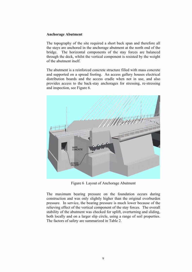
Anchorage Abutment The topography of the site required a short back span and therefore all the stays are anchored in the anchorage abutment at the north end of the bridge. The horizontal components of the stay forces are balanced through the deck, whilst the vertical component is resisted by the weight of the abutment itself. The abutment is a reinforced concrete structure filled with mass concrete and supported on a spread footing. An access gallery houses electrical distribution boards and the access cradle when not in use, and also provides access to the back-stay anchorages for stressing, re-stressing and inspection, see Figure 6.
Figure 6 Layout of Anchorage Abutment
The maximum bearing pressure on the foundation occurs during construction and was only slightly higher than the original overburden pressure. In service, the bearing pressure is much lower because of the relieving effect of the vertical component of the stay forces. The overall stability of the abutment was checked for uplift, overturning and sliding, both locally and on a larger slip circle, using a range of soil properties. The factors of safety are summarized in Table 2.
9
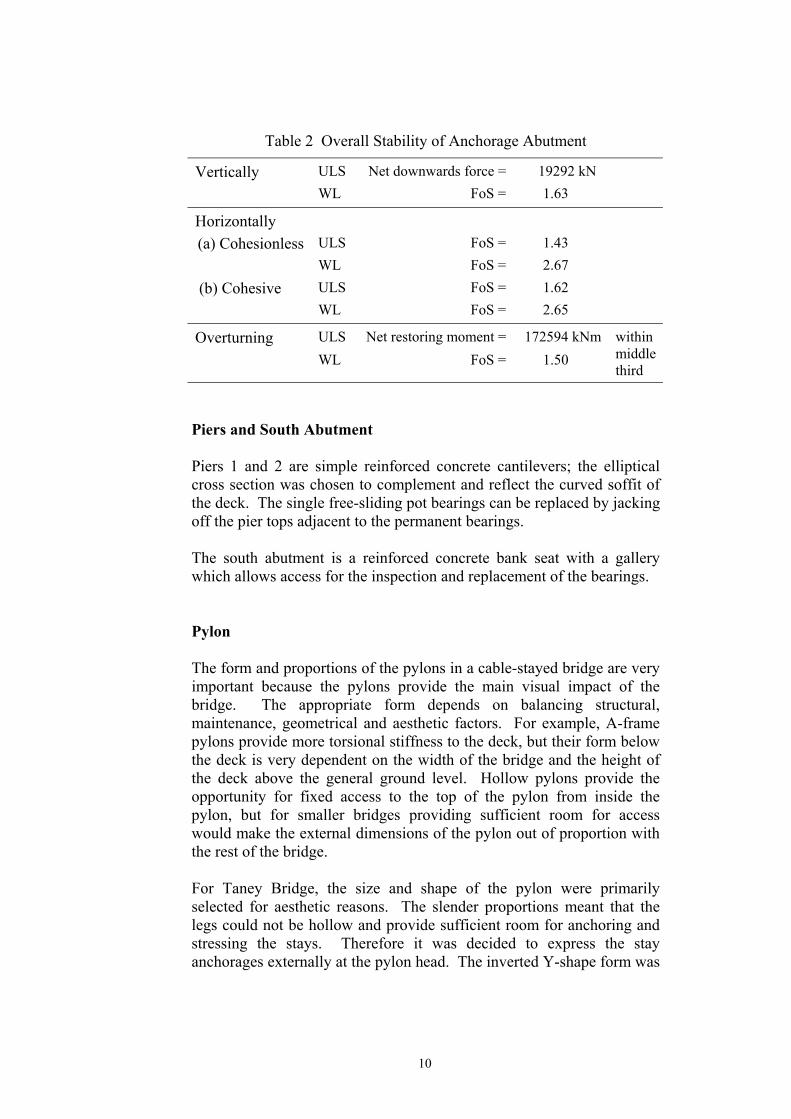
Table 2 Overall Stability of Anchorage Abutment
Vertically ULS Net downwards force = 19292 kN WL FoS = 1.63
Horizontally (a) Cohesionless ULS FoS = 1.43
WL FoS = 2.67 (b) Cohesive ULS FoS = 1.62 WL FoS = 2.65
Overturning ULS Net restoring moment = 172594 kNm
WL FoS = 1.50 within middle third
Piers and South Abutment Piers 1 and 2 are simple reinforced concrete cantilevers; the elliptical cross section was chosen to complement and reflect the curved soffit of the deck. The single free-sliding pot bearings can be replaced by jacking off the pier tops adjacent to the permanent bearings. The south abutment is a reinforced concrete bank seat with a gallery which allows access for the inspection and replacement of the bearings. Pylon The form and proportions of the pylons in a cable-stayed bridge are very important because the pylons provide the main visual impact of the bridge. The appropriate form depends on balancing structural, maintenance, geometrical and aesthetic factors. For example, A-frame pylons provide more torsional stiffness to the deck, but their form below the deck is very dependent on the width of the bridge and the height of the deck above the general ground level. Hollow pylons provide the opportunity for fixed access to the top of the pylon from inside the pylon, but for smaller bridges providing sufficient room for access would make the external dimensions of the pylon out of proportion with the rest of the bridge. For Taney Bridge, the size and shape of the pylon were primarily selected for aesthetic reasons. The slender proportions meant that the legs could not be hollow and provide sufficient room for anchoring and stressing the stays. Therefore it was decided to express the stay anchorages externally at the pylon head. The inverted Y-shape form was
10

chosen for aesthetic reasons and to enhance the torsional stiffness provided by the stay system. A solid wall was selected below deck level as the height above ground is limited and the soffit of a cross beam would have been very close to the ground. The top of the wall provides adequate space for two bearings with room to jack the deck to allow for bearing replacement. The bridge is designed so that the horizontal forces in the back stays balance those in the fore stays under the effect of the permanent loads on the bridge. The forces in the pylon due to other load effects were calculated using a plane frame analysis. Structurally, the pylon is a tall slender stayed strut and it is important that second order (P – ∆) effects are properly considered. It is well-known that the approach adopted for the design of slender columns in BS5400: Part 41 is conservative and, therefore, a study was made of other approaches to this problem including a full non-linear analysis3. The method finally adopted was based on the approach described in the FIP Recommendations4 which involves factoring the first order
deflection, including the effects of creep and shrinkage, by 1
1−
−
crPP
and calculating a second order moment by multiplying this deflection by the applied axial load (P). This approach requires the effective length of the pylon to be determined in order to estimate the critical buckling load (Pcr) using a reduced flexural stiffness which takes account of creep and the reduction in stiffness as the ultimate limit state is approached. The effective lengths of the pylon were assessed from the results obtained from a linear buckling analysis of a 3-dimensional space-frame model of the bridge. The layout of the tendon anchorages in the pylon head induce high local transverse tensile forces on the north (anchorage abutment side) face of the pylon. The pylon head was designed using a strut-and-tie approach, see Figure 7, and a steel plate designed to carry the transverse tension. It was then decided to make use of this steel plate and a similar one on the other face to help align the cable stay form tubes which run through the pylon. By welding the tubes to the steel plates to form a rigid structure it is possible to accurately align the tubes in the fabrication shop so that on site it is only necessary to level in each assembly to achieve the correct spatial positioning of the form tubes, Figure 8.
11

Figure 7 Strut-and-tie Model at Pylon Head
Figure 8 Pylon Head Steel Assembly
Wherever possible the pylon was designed so that the vertical reinforcement was not required to carry compression. This meant that
12

alternate vertical bars did not need to be restrained and greatly simplified the link arrangement. Besides the lightning conductor and aircraft warning light, a radio antenna forming part of the light railway communication systems is located at the top of the pylon. Access to the platform at the pylon top is by a demountable lightweight cradle which runs up either side face of the pylon, Figure 9.
Figure 9 Demountable Access Cradle
Deck A multi-stay cable-stayed bridge is a highly redundant structure and the designer has the opportunity to use the stays to prestress the deck and adjust the force distribution under permanent loading. For Taney Bridge the fore stay forces under permanent loading were chosen so that the total moment range over most of the deck was symmetrical with equal hogging and sagging moments. This approach allowed the use of axial
13

prestressing in the deck to supplement the axial compression from the cable stays. Determining the forces in the deck due to other loads was carried out using linear elastic analysis of a 2-dimensional plane frame model. A 3-dimensional linear elastic model was used to determine torsional effects in the deck, while non-linear analysis was used to assess transverse wind loading. The natural frequencies and modal shapes were also determined in order to assess the response of the bridge to aerodynamic excitation and the passage of trains5. All analyses were carried out using the Lusas computer program. The effects of differential temperature through the deck beam can be significant in prestressed concrete bridges and is considerably influenced by shading on the top surface due to road surfacing or other material. The rail tracks on Taney Bridge are fixed to reinforced concrete plinths which have transverse joints, at between 5 and 10 m centres longitudinally, so that they do not attract excessive loads due to flexure of the deck. The considerable variation in structural depth across the cross-section will also affect the stresses induced by differential temperature. The deck was idealized as a number of vertical strips each with its own temperature distribution and the cross-section analysed to determine the self-equilibrating stress distribution and the change in length and curvature. These results were combined with the effects of overall temperature changes and temperature differences between the deck and the stays in order to calculate the overall effects of temperature changes. Five different temperature combinations were considered and these are summarized in Table 3.
Table 3 Temperature Loadcases
Loadcase Deck Pylon Stays
Positive Temperature Difference Temp. +10ºC +10ºC +20ºC 1 Diff. Temp. positive curvature to main span – Temp. +27ºC +27ºC +41ºC 2 Diff. Temp. positive curvature to main span –
Reverse Temperature Difference Temp. +25ºC +25ºC +33ºC 1 Diff. Temp. reverse curvature to abutment Temp. -25ºC -25ºC -32ºC 2 Diff. Temp. reverse curvature to abutment Temp. +25ºC +25ºC +18ºC 3 Diff. Temp. reverse curvature to abutment
14
The long-term effects of creep and shrinkage were investigated using an iterative technique to allow for the (generally) relieving effect of forces induced by creep in earlier time periods. The total free specific creep and shrinkage strain was divided into ten equal increments and the strain occurring in each increment was calculated by multiplying the forces in the structure at the beginning of an increment by the specific strain occurring during that increment. The forces induced were then added to the forces at the beginning of the increment and the process repeated. The studies showed that the most significant effect was the axial shortening of the deck which reduced the loads in the stays, causing the deck to sag and increasing the hogging moment at Pier 2. The increase in moment was greater than that initially expected by the designer. The aerodynamic response of the bridge was assessed both in service and during construction using the data provided in BD49/01, as implemented by the NRA6. The bridge was assessed as a Type 4 cross section, see Figure 10, but because it does not meet all the conditions in
Figure 10 Cross-section for Aerodynamic Evaluation
BD49/01 checks were also carried out for cross sections Types 3A and 4A. The results for the Type 4 cross section are presented in Table 4. A more detailed discussion is given by Wilson et al 5. The theoretical assessment showed that the dynamic loading due to vortex induced oscillations was low except for the higher modes. These would only be induced in steady wind speeds of over 100 kph and it is considered highly unlikely that such steady wind speeds would occur at the bridge site over long enough periods for any oscillations to build up. The critical wind speeds for the onset of galloping and flutter both in-service and during construction were assessed as being at least 100 m/s, well above the required value of 45.3 m/s. It was therefore concluded that the deck would remain stable under all design wind conditions and that any oscillations induced by vortex shedding would be small and no more severe than the static wind loading.
15

Table 4 Dynamic Loads due to Vortex Shedding
In-service Mode B1 B2 T1 B3 B4 T2 B5 Natural frequency, (Hz) 0.73 1.32 1.91 2.02 2.89 3.37 4.00 Critical wind speed (m/s) 6.3 11.4 16.4 17.4 24.9 29.0 34.5 No. of half wavelengths in span 1 2 1 3 4 2 5 Dynamic load, (kN/m, kNm/m) 0.9 3.1 8.5 7.2 14.7 26.4 28.1
During construction Mode B1 B2 T1 B3 B4 B5 Natural frequency, (Hz) 0.42 0.83 1.45 1.47 2.29 3.32 Critical wind speed (m/s) 3.4 6.7 11.8 11.9 18.6 27.0 No. of half wavelengths in span 1 2 1 3 4 5 Dynamic load, (kN/m, kNm/m) 0.3 1.0 2.6 6.3 16.1 14.0
Bn, Tn B = bending; T = torsion; , n = mode number The effect of two adjacent cables being ruptured as a result of an accident or other cause was investigated by carrying out a simplified plastic analysis using the 3-dimensional model of the bridge in which hinges were progressively introduced into the structure at points where the ultimate bending or torsional capacities were reached. The shear capacity was checked to ensure that failure in shear did not occur. It was found that the structure did not become a mechanism and therefore would continue to support the specified loading during and after the stays ruptured. This is an upper bound approach, but is considered appropriate because of the number of conservative assumptions that had been made. Match-casting was selected for the main span over the junction as the precast units could be erected quickly in cantilever and therefore cause minimal disruption to traffic. In order to limit the number of junction closures and restrictions, it was decided to install the cables to their full load, avoiding the need for subsequent re-tensioning which would require access from underneath the deck. However, such a construction method, when combined with a concrete strength of 60 MPa (which was considered to be a reasonable maximum) and typical creep properties, required the depth of the deck at Pier 2 and at the pylon to be increased. A small scale model was built to assess the aesthetics of these local increases in depth and used to refine the deck soffit profile. It was decided to construct the approach spans and anchor span in insitu concrete, as this would allow the variation in depth to be formed more economically.
16

The 3.5 m long precast units were joined with epoxy adhesive and prestressed together using 40 mm diameter Macalloy bars. Bars were selected to minimize losses due to the short tendon length, which typically extended only 2 or 3 units to allow the permanent prestress to be used for construction, Figure 11. The bars were located in ducts
Figure 11 Cross-section through Precast Deck Unit
through the precast units and were to be grouted after stressing. Some additional temporary prestress was also required. In using grouted internal tendons in precast construction, it was recognized that the method of jointing the sheathing between adjacent units would be critical in ensuring a durable structure and, therefore, an indicative method for achieving this was given in the tender drawings. BS5400: Part 41 does not allow tension at epoxy joints under any load combination and hence the critical sections for design were the joints under Combination 3 loading which includes temperature effects. Therefore, it was important, in order for the design to be efficient, not to over-estimate the effects of temperature. The reinforced concrete edge beams were precast in order to obtain a high quality finish and they were placed on the deck during cantilever erection in order to have maximum load on the bridge when tensioning the cable stays. Once the deck was completed, the edge beams were finally aligned and fixed in position to give a good line and further enhance the slenderness of the deck. A bespoke combined footway/cycleway handrailing was designed by the Railway Procurement Agency’s architects and engineered by Roughan and O’Donovan. This was fabricated from stainless steel and further adds to the visual appeal of the bridge, Figure 12.
17

Figure 12 Stainless Steel Parapet
Cable Stays The details developed for the tender specified parallel wire stays because these are slightly more compact than parallel strand stays, but tenderers were permitted to propose the use of the latter provided they included within their tender price the cost for undertaking any re-detailing necessary to accommodate the different stays. In the event the successful contractor opted for parallel strand stays. Each stay consists of between 16 and 37 no. 15.7 mm diameter galvanized high-tensile 7-wire strands. Each strand has its own tight-fitting, extruded high density polyethylene (hdpe) sheath and the bundle of strands is encased in an outer hdpe sheath of between 140 and 180 mm OD. The outer sheathing was specified with a 2 mm high double helical rib at approximately 600 mm pitch to prevent wind-rain induced vibrations. The back stays were detailed to be stressed and adjusted from the access gallery built into the anchorage abutment, while the fore stays were specified to be stressed and adjusted from below the deck since there is no permanent fixed access to the pylon anchorages. The maximum stress at the serviceability limit state in the strands forming the stays is 45% of the characteristic tensile strength of the
18

strands, i.e. 796.5 MPa. This was allowed to increase to 55% during installation. The stress range under variable loads is limited to 200 MPa. The overall diameters of the stays are relatively small and there is a possibility that the stays might vibrate either from wind effects or due to resonance as trains pass over the bridge. The dynamic response of the bridge and cables depends on the interaction between many parameters and on their actual values in the finished structure. These are impossible to predict precisely at the design stage and therefore it was specified that the detail design of the cable stays should allow dampers to be incorporated at a later stage with little or no modification to the structure, should this prove necessary. A provisional item for the supply and installation of six dampers was included in the tender in order to obtain competitive prices should these subsequently be required. The critical aspect of cable stay performance is their behaviour under fluctuating loads. In Taney Bridge, the cable stay anchorages are effectively fixed to the bridge deck so that the ends of the cables are subject to flexure under wind, temperature and live loading. Hence, the stays experience variations not only in axial stress, but also in flexural stress. Generally only axial loads are applied to cable stays in standard fatigue tests and therefore any reduction in fatigue performance due to fluctuating flexural loads would not be evident. Hence, three fatigue tests on full-size stays were specified for Taney Bridge, Table 5, including one in which the anchorage was rotated through 0.5° for one million cycles as analysis had shown that the stays could experience a rotation range of this order The specification stated that historical test data on stays and anchorages of the same construction, assembly and constituent parts and subject to the same stress ranges may be acceptable at the discretion of the Engineer.
Table 5 Stress Ranges for Fatigue Tests (σs = nominal tensile strength of wire)
Upper Stress Level
Axial Stress Range (MPa)
Anchorage Rotation Range
Cycles
0.45σs 162 – 2 x10⁶
0.45σs 197 0.5° 1 x 10⁶
0.45σs 197 – 1 x 10⁶
Recent developments in the design of parallel strand cable stay anchorages has concentrated on attenuating the stresses in each strand due to rotation of the cable within the transition zone immediately behind the anchorage block rather than by the overall behaviour of the
19

deviator, guide pipes and anchorage. This has two consequences. Firstly, useful and relevant feedback on the fatigue performance of the complete stay can be obtained by testing a single strand in a monostrand anchorage, provided the anchorage is of similar construction and longitudinal dimensions to the multi-strand anchorages to be used in the actual bridge. Secondly, such a design allows the deviator to be easily replaced by a friction damper, should damping of the stay prove necessary in practice. The VSL SSI 2000 stay cable system proposed by the contractor is such a system and an appropriate axial and rotational fatigue test of a monostrand stay and anchorage was developed through discussions between the Engineer and VSL. A new test rig was commissioned by VSL and constructed at the EMPA testing laboratories in Zurich, Figure 13. There were no wire breakages during the one million fatigue cycles
and the residual static strengt97.7% of the actual ultimate teand 105.8% of its characteristexcellent result. Failure was dthe strand within the anchorage
(a) Transverse displacement Figure 13 C
TEND The initial construction programBypass overlapped with the lmonths ahead of the former. within the site for the Dund
h of the strand was 281 kN. This was nsile strength of the non-fatigued strand ic ultimate tensile strength, which is an ue to the breakage of two outer wires of wedges.
(b) Longitudinal displacement able Stay Fatigue Test
ER PROCESS
mes for Taney Bridge and the Dundrum atter starting on site approximately nine As the foundations for the bridge were rum Bypass and in order to allow the
20
completion of the bridge as early as possible, it was decided to include the construction of the bridge foundations within the Bypass contract. For a number of reasons there was a delay in the award of the Bypass contract and in order to minimize any consequential delay to the completion of the bridge, the Railway Procurement Agency decided to construct the bridge foundations under a separate advance contract. Tenders for the construction of all the piles and the pylon pile cap were invited in early 2001 and the contract awarded to Rilmount Ltd and its piling subcontractor, Bachy-Soletanche, in May 2001. Tender documents for the main contract were issued in April 2001 and five tenders were returned. One tenderer offered an alternative method of construction and another offered an alternative design with a concrete/steel composite deck. The Railway Procurement Agency evaluated the tenders and determined the most economically advantageous tender on basis of:
• price, • construction methodology, • risk contingency, • programme for the works, • health and safety proposals, • traffic management proposals, and • project organisation.
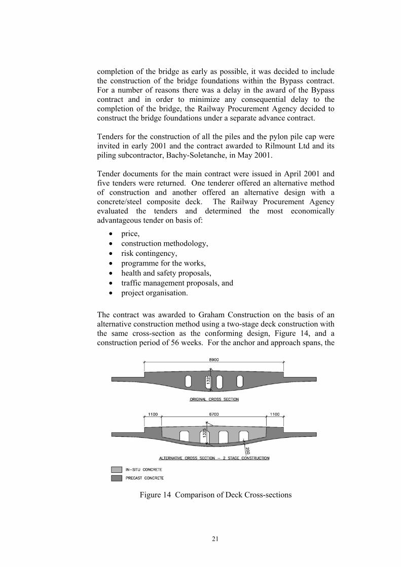
The contract was awarded to Graham Construction on the basis of an alternative construction method using a two-stage deck construction with the same cross-section as the conforming design, Figure 14, and a construction period of 56 weeks. For the anchor and approach spans, the
Figure 14 Comparison of Deck Cross-sections
21
precast shells were erected on falsework, while in the main span they were erected by cantilevering from the pylon. Each shell was stressed to the preceding shell using a combination of permanent and temporary 40 mm diameter VSL Stress Bars and the cable stays installed. When an appropriate length of deck had been erected, sheathing for strand prestressing tendons was placed in the precast shells which were then filled with insitu concrete. After the concrete had reached its required strength, the strand tendons were stressed and the temporary prestressing bars removed. The deck for the alternative construction method was designed for the contractor by Robert Benaim & Associates and checked by Roughan and O’Donovan. The advantages and disadvantages of this alternative construction method are summarized in Table 6.
Table 6 Advantages and Disadvantages of Alternative Construction Method
Advantages Disadvantages
Similar construction/appearance for whole deck
Each stay re-stressed up to 4 times during erection
Lighter precast units to erect Grade 65 concrete for precast units
Fewer bars to be installed and stressed during road closures – quicker erection
Grades 40 and 55 concrete for insitu infill
No duct joints between units – potentially better durability
Concrete mix designed to minimise long-term creep
The use of higher strength (65 MPa) concrete for the precast shells, estimating creep and shrinkage strains on the basis of the actual concrete mixes used and employing multi-stage tensioning of the cable stays allowed a constant depth deck to be used throughout the bridge.
CONSTRUCTION ISSUES The advance contract for the installation of the piles and pile cap for the pylon commenced at the end of May 2001. The installation of the 55 no. working piles took two months and was completed by the end of August 2001. The pylon pile-cap was 2.5 m deep and had a total volume of 955 m3. It was cast in one continuous pour at the beginning of October with thermocouples being used to monitor the temperature in the core and at several points on the face of the pile cap. Insulation was used in order to prevent the faces of the pile cap cooling too quickly. The top face of the
22
concrete near the centre of the pile cap remained within 20 °C of the central core temperature, but it proved impossible with the measures taken to limit the difference between the central core and the edge faces to this value. However, it is likely that the temperature at mid-depth of the pile cap near its edges was less than that of the central core, so that local differences would have been closer to 20 °C. Initially the temperature of the core reached 70 °C and it was still over 40 °C after a month, whilst the mean ambient temperature throughout this period was about 12 °C. With the foundations for the pylon completed, the construction of the Dundrum Bypass at Taney Cross could continue while the bridge contractor concentrated on constructing the pylon, the anchorage abutment and the back span of the bridge. The advance piling contract made provision for Rilmount Ltd – Bachy Soletanche to return in early 2002 to install the piles for Piers 1 and 2 and the South Abutment, this work being coordinated with that of the contractor for the Dundrum Bypass. The contract for the main bridge was awarded at the end of August 2001 with a start on site date of late October, once the pylon pile cap had cured sufficiently. This gave the contractor a lead-in time of approximately six weeks which enabled him to complete his preliminary planning and temporary works design so that an immediate start on the works could be made as soon as the site was available. Site work on the pylon commenced early in November 2001 and the bridge was completed ahead of programme in November 2002. From the start, Graham took the decision to provide falsework which would not only support the pylon forms, but provide easy, stable and protected access for workmen to all parts of the pylon. This proved its worth as there were no accidents on the pylon and the stable and protected environment allowed a high quality of workmanship to be achieved. The falsework arrangement was such that any deflections of the pylon sloped legs under wet concrete were minimal and, therefore, no geometric adjustments were needed in construction of the pylon. The steel plate and guide tube assemblies in the pylon head were relatively easy to position and level in accurately, but the steel plates restricted the placing of concrete in the critical cover zone between the plate and the formwork. It is felt that this could be made easier in future designs by introducing more holes through the plate to facilitate the flow of concrete and increasing the thickness of the plate to compensate for the loss of area.
23

The precast deck shells were produced in Graham’s yard in Dromore, Northern Ireland, using the short-line match-casting technique. After much research, the contractor commissioned a special mould, Figure 15,
Figure 15 Mould for Precast Shell
which had removable panels which could be replaced when required with panels incorporating the cable stay anchorage blisters which protruded from the deck soffit. Each pair of anchorages is at a different angle to the longitudinal centre-line of the deck. The contractor investigated whether a limited number of “standard” anchorage blisters would be possible, but eventually decided to adopt the specified arrangement and provide special panels for each anchorage. Part of the soffit panel was eventually used on site for forming the soffit of the insitu stitches at the end of the main span cantilever. The unstressed camber of the precast shells was determined by the contractor and checked by the Engineer. The unstressed camber is the deflected shape of the precast units when they are carrying no loads. The units are cast to this camber so that when they are erected and adjusted to their final specified alignment in the bridge, the stresses in the deck should correspond to those assumed in the design. With the short-line method of match-casting, precise surveys have to be carried out both before and after casting each unit so that any movements of the forms during casting can be corrected in setting up the next unit. If this were not done accurately, a small error in the relative alignment of adjacent units would become significant when magnified over the length of a 100 m cantilever. The contractor was responsible for designing traffic management measures and obtaining the approval of the Gardaí and the Local Road
24

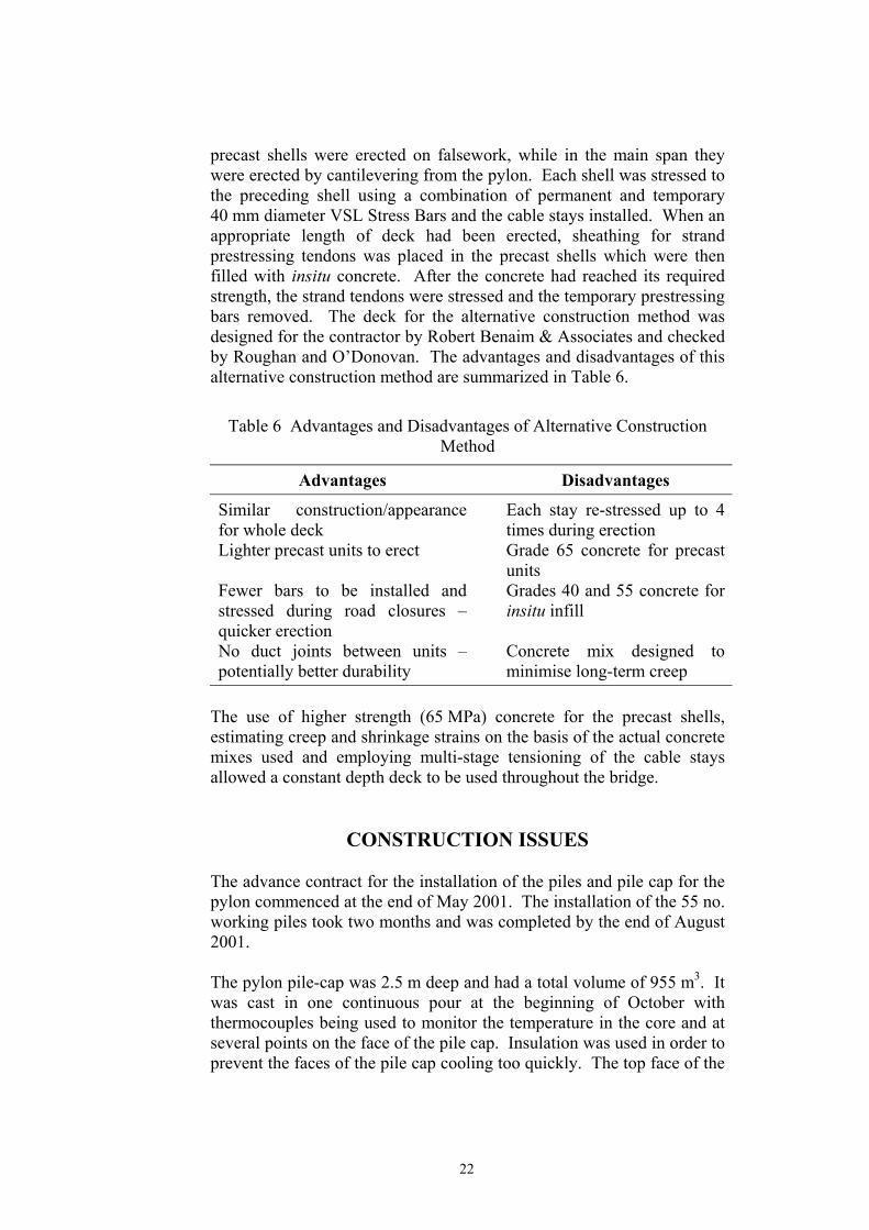
Authority. Graham appointed Roughan and O’Donovan under a separate contract to design appropriate traffic management schemes for the different stages of construction. Four temporary road layouts were used during the erection of the bridge and these are illustrated in Figure 16. The initial length of cantilever from the pylon was erected with Upper Churchtown Road closed and traffic diverted in advance of the bridge site. For the middle section of the cantilever, a roundabout scheme was used, whilst local width restrictions in the south east quadrant of the junction were employed during the erection of the southern end of the main span. These arrangements maintained all turning movements at the junction and could be employed overnight. A limited number of complete closures of the junction was permitted at weekends for those works which could not be completed under the other layouts. The traffic management measures worked well and the bridge was completed with minimal disruption to one of the main traffic junctions in south Dublin. When constructing the main span cantilever, the contractor was generally able to lift and stress one segment per night and to start the installation of the pair of cable stays, which, when necessary, was completed during the following night, Figure 17. All strands were installed in the shorter stays during the appropriate erection stage. Initially the stays are supporting only the self-weight of the precast shells and hence their installation load is relatively low with a correspondingly large sag in the stay. This caused the contractor problems in installing all the strands during the first stage for the longer, shallower stays. Therefore, it was decided to install initially only a proportion of the strands, to the same total stay load, with the remainder being installed at a later stage. The contractor prepared a table of the expected deflections of the deck and pylon at each construction stage. The deflections were checked by Roughan and O’Donovan who carried out its own independent analysis. Although there were differences in the results, it was decided to use a consistent set of figures which, if met at each stage, would eventually lead to the specified alignment being achieved at the end of construction. Vertical and horizontal deflections of the deck and verticality of the pylon were monitored during construction. Analyses were carried out for each construction stage with the effective stiffness of the stays adjusted to reflect the actual forces in the stay during that stage and the results compared with the measured values. Generally there was good agreement between the theoretical and measured values. The stays were installed using the single strand installation method. In this method the stay sheath is lifted with the first (master) strand. The
25

strand is connected at each end to the anchorages and stressed to a
Figure 16 Traffic Management Measures
26
predetermined force. The subsequent strands are installed one at a time, connected to the anchorages and stressed. As each subsequent strand is stressed, the loads in the previously installed strands reduce. The stressing load for each strand is determined automatically by an on-site laptop computer using the stay load at installation as specified by the designer and the theoretical stiffness of the bridge structure, allowing for cable sag.
Figure 17 Bridge during Segment Erection
The deck is relatively flexible and therefore a small change in stay force can result in a large vertical movement of the deck. The loads in the stays and the forces and bending moments in the deck can therefore be more precisely controlled by adjusting the length of the stay rather than its load. Therefore, subsequent adjustments to the cable stays were carried out by shortening each strand in a stay by a specified length. The adjustments specified on the design drawings were varied in practice in order to take into account actual site conditions and to keep the deck and pylon within the specified tolerances of their expected positions at each stage.
27
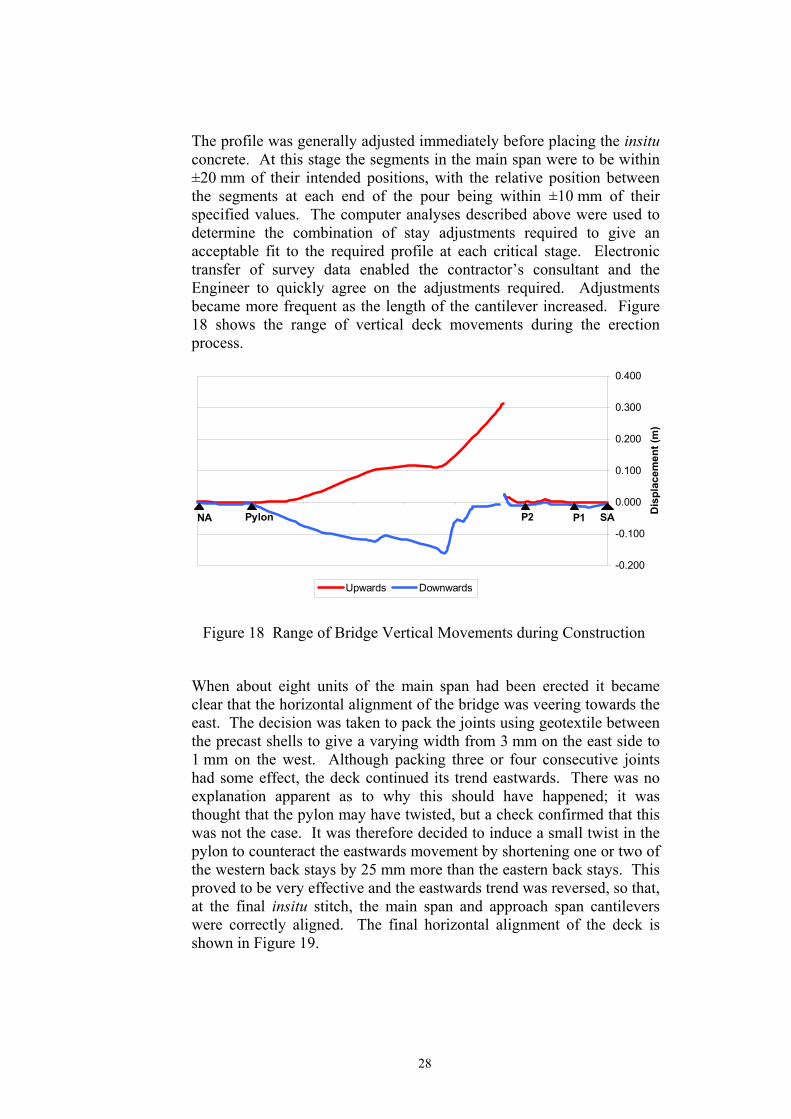
The profile was generally adjusted immediately before placing the insitu concrete. At this stage the segments in the main span were to be within ±20 mm of their intended positions, with the relative position between the segments at each end of the pour being within ±10 mm of their specified values. The computer analyses described above were used to determine the combination of stay adjustments required to give an acceptable fit to the required profile at each critical stage. Electronic transfer of survey data enabled the contractor’s consultant and the Engineer to quickly agree on the adjustments required. Adjustments became more frequent as the length of the cantilever increased. Figure 18 shows the range of vertical deck movements during the erection process.
-0.200
-0.100
0.000
0.100
0.200
0.300
0.400
020406080100120140160 Dis
plac
emen
t (m
)
Upwards Downwards
SAPylon P2 P1NA
Figure 18 Range of Bridge Vertical Movements during Construction
When about eight units of the main span had been erected it became clear that the horizontal alignment of the bridge was veering towards the east. The decision was taken to pack the joints using geotextile between the precast shells to give a varying width from 3 mm on the east side to 1 mm on the west. Although packing three or four consecutive joints had some effect, the deck continued its trend eastwards. There was no explanation apparent as to why this should have happened; it was thought that the pylon may have twisted, but a check confirmed that this was not the case. It was therefore decided to induce a small twist in the pylon to counteract the eastwards movement by shortening one or two of the western back stays by 25 mm more than the eastern back stays. This proved to be very effective and the eastwards trend was reversed, so that, at the final insitu stitch, the main span and approach span cantilevers were correctly aligned. The final horizontal alignment of the deck is shown in Figure 19.
28

-20.0
-10.0
0.0
10.0
20.0
30.0
40.0
50.0
020406080100120140160
Offs
et (m
m)
Corrected Survey Actual Position As-cast Profile
NA Pylon
P2 P1 SA
EAST
WEST
Figure 19 Horizontal Alignment of Deck
When the deck was structurally complete a final adjustment of the stays was carried out in order to bring the deck and pylon within the allowable tolerances of their specified profiles at this stage. The precast reinforced concrete edge beams where then positioned on the edge of the deck and locally adjusted to give a smooth line both vertically and horizontally before concreting the insitu stitch with the deck. Finally, the stainless steel parapet and other finishing works were completed, Figure 20.
Figure 20 Completed Bridge
29

COSTS The completed bridge was handed over ahead of programme in November 2002 to the Luas Line B contractor for him to install the track plinths, rails and overhead line equipment on the bridge. The final costs of the two contracts were approximately:
Piling contract: €1,800,000 Main contract: €9,300,000
This is equivalent to approximately €4,500 per m2 of deck.
CONCLUSION Taney Bridge is a major landmark in Dundrum. Its construction attracted a lot of public interest with people turning out in the evenings to watch segments being erected. Many local people have made their own photographic records of the construction. By considering methods of construction and bridge form at the concept design stage, it has been possible to design and construct an elegant, slender, modern bridge across one of the busiest traffic intersections in south Dublin with only minimum disruption to traffic using the surrounding streets. When Luas Line B is completed at the end of 2003, Taney Bridge will carry modern light-weight trams every five minutes safely and quickly above the congested roads below.
ACKNOWLEDGEMENTS The authors gratefully acknowledge the agreement of the Railway Procurement Agency (RPA) to publish this paper. Client: The Railway Procurement Agency Consulting Engineer: Roughan & O’Donovan Ltd Contractor: Graham Construction Piling Contractor: Rilmount Ltd with Bachy Soletanche The authors wish to acknowledge the support and assistance of Mr Pat O’Donoghue (Design Manager), Mr Michael O’Neill (Contracts Manager Line B) and their colleagues in the RPA. In addition they wish to record the major contribution of Mr Pat Maher, then Chief Bridge Engineer of Roughan & O’Donovan, to the production of the preliminary design of Taney Bridge in 1997.
30
REFERENCES 1 BS5400:Part 4: 1990 Code of practice for the design of concrete
bridges, British Standards Institution, London, 1990. 2 Fleming, W.G.K., A new method for single pile settlement prediction
and analysis, Geotechnique No.42, London 1992. 3 O’Donovan, P.J, Wilson, K.R and Dempsey, A.T, Second order effects
in the design of concrete pylons for cable-stayed bridges, to be published in 2003.
4 Fédération Internationale de la Précontrainte, Practical design of reinforced and prestressed concrete structures, Thomas Telford Ltd, London, 1984.
5 Wilson, K.R and Dempsey, A.T, Dynamic considerations in the design of Taney Bridge, to be published in 2003.
6 BD49/01 Design rules for aerodynamic effects in bridges, NRA Design Manual for Roads and Bridges, NRA, Dublin, Dec. 2000.
31

APPENDIX: TANEY BRIDGE – DESIGN CRITERIA The bridge shall be designed in accordance with the appropriate parts of BS5400 and the following requirements. (i) Treatment of Cable Stay Forces at ULS
The prestrain in the cable stays is defined as the difference between the loads in the cable stays under permanent loading and those which would be introduced were the permanent loads to be applied as an external load to the final structure. A γfL of 1.05 or 0.95 shall be applied to the prestrain loadcase which shall then be added to the permanent loadcase and a γfL of 1.15 or 1.00 applied to the sum.
(ii) Superimposed Dead Load γfL of 1.0 (SLS) and 1.2 (ULS) shall be applied to all superimposed dead loads except the self-weight of the rails and the variable part of the track plinths where γfL of 1.2 (SLS) and 1.75 (ULS) shall be used.
(iii) Railway Live Loading Vertical Load
25 kN/m per track over any length. This load shall be multiplied by a dynamic amplification factor of 1.5, except where noted below. Braking and Traction Loading
Traction: 2.50 kN/m ≤ 250 kN Braking: 6.25 kN/m ≤ 625 kN
(iv) Differential Settlement A long-term differential settlement of ±10 mm at any foundation.
(v) Differential Temperature between Deck and Cable Stays In determining temperature effects, the deck and pylon shall be treated as Group 4 structures and the cable stays as Group 1 structures with waterproofing to allow for the effects of the protective sheathing. In order to allow for temperature variations during construction, increases in temperature shall be calculated
32

from a mean of +5 °C and decreases in temperature from a mean of +15 °C. Effective temperatures in the deck and cable stays (including the differences between them) shall be combined with differential temperatures in the deck and pylon in accordance with clause 5.4.5.2 of BD 37/88.
(vi) Impact Loading The piers and pylon shall be designed against vehicle impact in accordance with BD 60/94. The pylon shall also be designed against impact from a train by applying BD 60/94 and considering the track as if it were a highway.
(vii) Cable-out Scenarios
The bridge shall be designed for the following “cable-out” scenarios:-
a) Moment of Impact
ULS only. Live load applied only to the track adjacent to ruptured cable stays, with a dynamic factor of 1.5. Any two adjacent cable stays in the same line assumed to be ruptured. The complete structure (with all cable stays) shall be analysed using the partial factors specified below. The effect of rupturing cable stays to be assessed by applying forces equal and opposite to twice the load in the ruptured cable stays under the specified loading to the structure without these cable stays, with no other loads acting on the structure. The results of the two analyses shall be combined.
γfL DL 1.0 Parasitics 1.0 SDL 1.2 / 1.0 LL 1.1
γm Concrete 1.5 Rebar 1.15 Prestress 1.15 Cable stays 1.3
33
γf3 = 1.1
b) Immediately after Impact
ULS only. Live load applied to both tracks. The dynamic factor shall only be applied to the live load on the track remote from the ruptured cables. Any two adjacent cable stays in the same line assumed to be ruptured. The structure with the two ruptured cable stays omitted shall be analysed using the partial factors specified in (a).
c) Cable Replacement
Load combinations 1, 2 and 3 shall be considered at ULS and SLS, as appropriate, with: -
• any one stay removed, • live loading on the track remote from the stay being
replaced. No dynamic factor need be considered as speed restrictions will apply, and
• a load of 5 kN/m over a 30 m length of track adjacent to the stay being replaced.
(viii) Prestressed Concrete Design
The insitu portions of the deck shall be considered as Class 1 under Load Combination 1 and Class 2 under Load Combinations 2 to 5. At the joints, the precast portions of the deck shall be considered as Class 1 under all load combinations. Away from the joints, the precast units may be considered as Class 1 under Load Combination 1 and Class 2 under Load Combinations 2 to 5.
(ix) Shear and Torsion
a) Longitudinal Shear
Where the shear force is of the same sign throughout a segment, the longitudinal shear force shall be averaged over the length of the segment. In a segment where the shear force changes sign, the shear force shall be separately averaged over the lengths where the shear force is of the same sign.
The longitudinal shear flow shall be checked on the following shear planes:
• a – a, the interface between the precast and insitu concrete, and
• for the voided sections, b – b, a plane in the insitu concrete running horizontally through the top of the
34

35
inner webs and vertically through the top slab on the line of the outer face of the outer voids.
The longitudinal shear capacity shall be calculated in accordance with BS5400: Part 4 clause 7.4.2.3, with the length of the shear plane, Ls, determined ignoring the vertical sections of the shear plane.
When V1 < v1Ls, no additional reinforcement need be provided across shear plane a – a. When V1 ≥ v1Ls on plane a – a and in all cases for plane b – b, minimum, fully anchored, reinforcement equal to 0.15% of the area of the shear plane shall be provided.
Reinforcement in the diaphragm of the precast units may be taken into account as contributing to the required reinforcement area where it passes across the relevant shear plane and is fully anchored.
b) Flexural Shear
The deck shall be treated as a beam and the minimum shear reinforcement required by BS5400: Part 4 shall be provided.
If no reinforcement is provided across the interface between the insitu and precast concrete then the vertical shear force should be apportioned between each element on the basis of cross sectional area with due allowance for the different grades of concrete. The breadth of the insitu concrete should be taken as the distance between the precast webs and the depth as the mean effective depth to the tendons or its actual mean depth, whichever is the lesser. The shear capacity of the precast unit should be based on the width of its webs and the mean effective depth to the tendons. In this case, the shear reinforcement in the insitu concrete need not extend into the precast unit.
c) Torsion
As well as providing sufficient longitudinal reinforcement or prestress, sufficient torsional hoop reinforcement will be required in the bottom flange and webs of the precast section and in the top of the insitu concrete, in addition to that required for other effects. Torsion may be carried by one or more concentric hoops.
At no section shall the sum of the torsional and flexural shear stresses exceed the maximum allowable stress specified in BS5400: Part 4.