Embed Size (px)
Citation preview
1
Tolerance Limits and Action Levels for Planning and
Delivery of IMRT QA
Jatinder R. Palta PhDDepartment of Radiation Oncology
University of FloridaGainesville, Florida
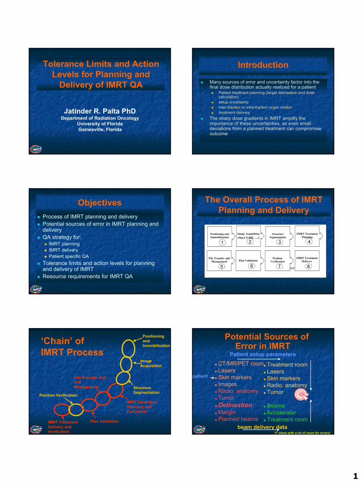
Introduction
Many sources of error and uncertainty factor into the Many sources of error and uncertainty factor into the final dose distribution actually realized for a patientfinal dose distribution actually realized for a patient
Patient treatment planning (target delineation and dose Patient treatment planning (target delineation and dose calculation)calculation)setup uncertaintysetup uncertaintyinterinter--fraction or intrafraction or intra--fraction organ motionfraction organ motiontreatment deliverytreatment delivery
The sharp dose gradients in IMRT amplify the The sharp dose gradients in IMRT amplify the importance of these uncertainties, as even small importance of these uncertainties, as even small deviations from a planned treatment can compromise deviations from a planned treatment can compromise outcomeoutcome
ObjectivesProcess of IMRT planning and deliveryPotential sources of error in IMRT planning and deliveryQA strategy for:
IMRT planningIMRT deliveryPatient specific QA
Tolerance limits and action levels for planning and delivery of IMRTResource requirements for IMRT QA
The Overall Process of IMRT Planning and Delivery
IMRT Treatment Planning
Image Acquisition(Sim,CT,MR, …)
Structure Segmentation
Positioning and Immobilization
File Transfer and Management
IMRT Treatment Delivery Plan Validation
Position Verification
1 2 3 4
5 6 7 8
Positioning and Immobilization
Image Acquisition
Structure Segmentation
IMRT Treatment Planning and Evaluation
File Transfer and and Management
Plan ValidationIMRT Treatment Delivery and Verification
‘Chain’ of IMRT Process
Position Verification
Potential Sources of Error in IMRT
CT/MR/PET roomLasersSkin markersImagesRadio. anatomyTumorDelineationMarginPlanned beams
Treatment roomLasersSkin markersRadio. anatomyTumor
BeamsAcceleratorTreatment room
17 steps with a lot of room for errors!
Patient setup parameters
beam delivery data
patient
2
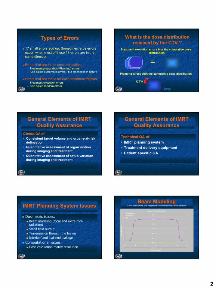
Types of Errors
17 small errors add up. Sometimes large errors occur: when most of these 17 errors are in the same direction
Errors that are made once per patient:– Treatment preparation (Planning) errors– Also called systematic errors - but stochastic in nature
Errors that are made for each treatment fraction:– Treatment execution errors– Also called random errors
What is the dose distribution received by the CTV ?
Treatment execution errors blur the cumulative dose distribution
Planning errors shift the cumulative dose distribution
Dose
CTV
General Elements of IMRT Quality Assurance
Clinical QA of: Consistent target volume and organs-at-risk delineationQuantitative assessment of organ motion during imaging and treatmentQuantitative assessment of setup variation during imaging and treatment
General Elements of IMRT Quality Assurance
Technical QA of:IMRT planning systemTreatment delivery equipmentPatient specific QA
IMRT Planning System Issues
Dosimetric issues:Beam modeling (focal and extra-focal radiation)Small field outputTransmission through the leavesInterleaf and leaf-end leakage
Computational issues:Dose calculation matrix resolution
Beam Modeling(Cross beam profile with inappropriate modeling of extra-focal radiation)
Measured vs. Calculated
-0.2
0.0
0.2
0.4
0.6
0.8
1.0
1.2
-15 -10 -5 0 5 10 15
Off-Axis (cm)
Relat
ive P
rofile
ADAC(4mm)wobkmlctrDiff
3
Beam Modeling(Cross beam profile with appropriate modeling of extra focal radiation)
-0.2
0.0
0.2
0.4
0.6
0.8
1.0
1.2
-15 -10 -5 0 5 10 15
Off-Axis (cm)
Rel
ativ
e D
iffer
ence
diff(w/bk)diff(wobk)wbkmlctrwobkmlctr
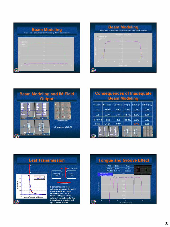
Beam Modeling(Cross beam profile with inappropriate modeling of extra-focal radiation)
Measured vs. Calculated
-0.2
0.0
0.2
0.4
0.6
0.8
1.0
1.2
-15 -10 -5 0 5 10 15
Off-Axis (cm)
Relat
ive P
rofile
ADAC(4mm)wobkmlctrDiff
Beam Modeling and IM Field Output
Segment 1 Segment 2
Segment 3 Segment 8
Segment 4-7, 9-13
13 segment IM Field
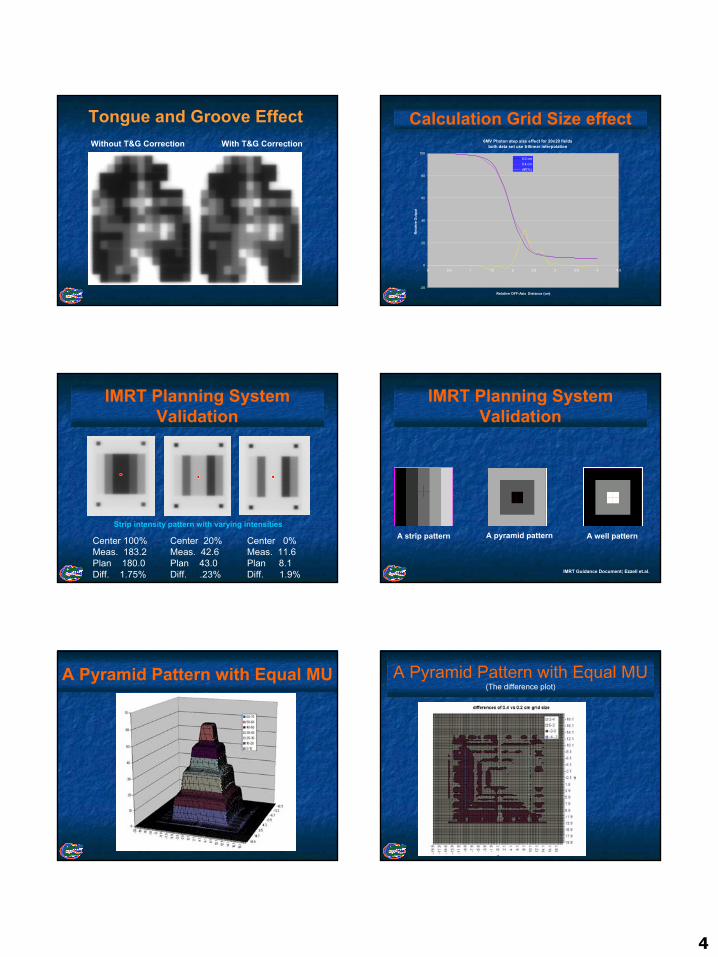
Consequences of Inadequate Beam Modeling
5.056.7%69.974.95Total0.390.5%29.9%1.31.694-7,9-13
3.915.2%13.7%28.532.413,8
0.650.9%1.6%40.240.851-2
Diff(abs)cGyDiff(abs)%Diff(%)CalculatedMeasuredSegments
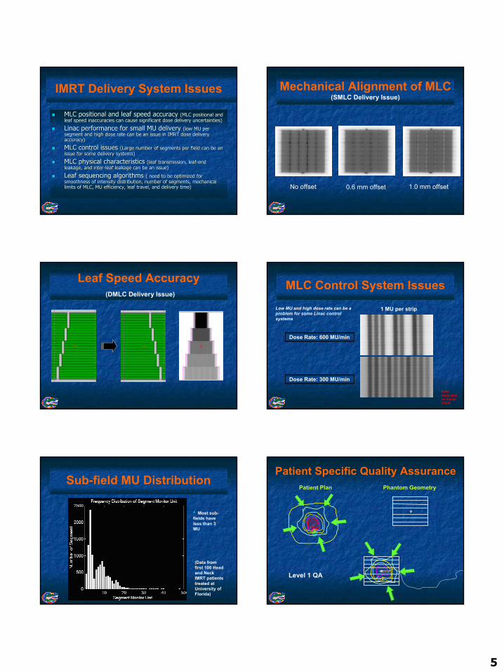
Leaf Transmission
0
0.2
0.4
0.6
0.8
1
-0.5 0 0.5 1
AnalyticMonte Carlo
Tran
smis
sion
Position relative to leaf tip (cm)
Window width
LeadingLeaf
FollowingLeaf
Leaf motion
Discrepancies in dose delivered increases for small window width and large number of MU. This is because of approximate nature of corrections for leaf transmission, rounded leaf tips, and leaf scatter
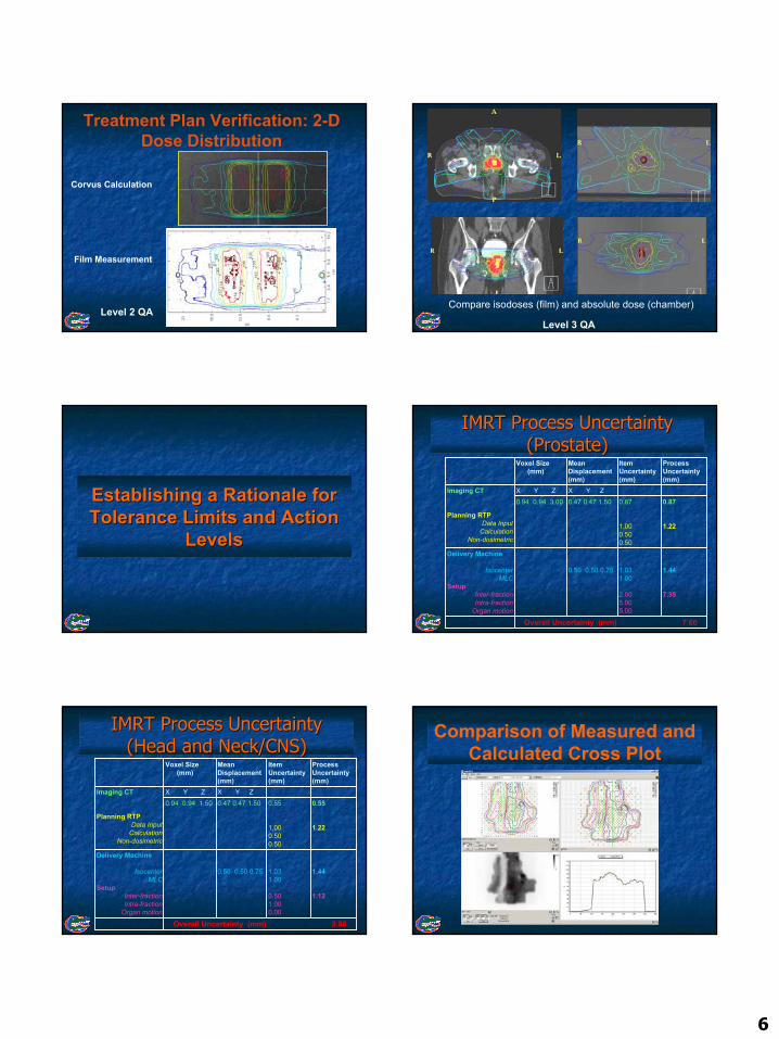
Tongue and Groove EffectMLC Elekta Varian
FWHM 3.3 mm 2.0 mmAvg. Min 0.76 mm 0.83 mm
0.7
0.75
0.8
0.85
0.9
0.95
1
1.05
-15 -10 -5 0 5 10 15
Off-Axis Distance (cm)
Rel
ativ
e Pr
ofile
MLC upper jawMLC Tertiary Collimator
4
Tongue and Groove EffectWithout T&G Correction With T&G Correction
Calculation Grid Size effect6MV Photon step size effect for 20x20 fields
both data set use trilinear interpolation
-20
0
20
40
60
80
100
0 0.5 1 1.5 2 2.5 3 3.5 4 4.5
Relative OFF-Axis Distance (cm)
Rel
ativ
e O
utpu
t
0.2 cm0.4 cmdiff(%)
IMRT Planning System Validation
Center 100% Meas. 183.2 Plan 180.0 Diff. 1.75%
Center 20% Meas. 42.6 Plan 43.0 Diff. .23%
Center 0% Meas. 11.6 Plan 8.1 Diff. 1.9%
Strip intensity pattern with varying intensities
IMRT Planning System Validation
IMRT Guidance Document; Ezzell et.al.
A strip pattern A pyramid pattern A well pattern
A Pyramid Pattern with Equal MU A Pyramid Pattern with Equal MU(The difference plot)
5
MLC positional and leaf speed accuracy MLC positional and leaf speed accuracy (MLC positional and (MLC positional and leaf speed inaccuracies can cause significant dose delivery unceleaf speed inaccuracies can cause significant dose delivery uncertainties)rtainties)
Linac Linac performance for small MU delivery performance for small MU delivery (low MU per (low MU per segment and high dose rate can be an issue in IMRT dose deliverysegment and high dose rate can be an issue in IMRT dose deliveryaccuracy)accuracy)
MLC control issues MLC control issues (Large number of segments per field can be an (Large number of segments per field can be an issue for some delivery systems)issue for some delivery systems)
MLC physical characteristics MLC physical characteristics (leaf transmission, leaf(leaf transmission, leaf--end end leakage, and interleakage, and inter--leaf leakage can be an issue)leaf leakage can be an issue)
Leaf sequencing algorithms Leaf sequencing algorithms ( need to be optimized for ( need to be optimized for smoothness of intensity distribution, number of segments, mechansmoothness of intensity distribution, number of segments, mechanical ical limits of MLC, MU efficiency, leaf travel, and delivery time)limits of MLC, MU efficiency, leaf travel, and delivery time)
IMRT Delivery System Issues Mechanical Alignment of MLC (SMLC Delivery Issue)
No offset 0.6 mm offset 1.0 mm offset
Leaf Speed Accuracy(DMLC Delivery Issue)
MLC Control System Issues
Dose Rate: 300 MU/min
Dose Rate: 600 MU/min
1 MU per stripLow MU and high dose rate can be a problem for some Linac control systems
Data measured on Varian 2100C
Sub-field MU Distribution
(Data from first 100 Head and Neck IMRT patients treated at University of Florida)
• Most sub-fields have less than 3 MU
Patient Plan Phantom Geometry
Patient Specific Quality Assurance
Level 1 QA
6
Corvus Calculation
Film Measurement
Treatment Plan Verification: 2-D Dose Distribution
Level 2 QACompare isodoses (film) and absolute dose (chamber)
Level 3 QA
Establishing a Rationale for Establishing a Rationale for Tolerance Limits and Action Tolerance Limits and Action
LevelsLevels
IMRT Process Uncertainty IMRT Process Uncertainty (Prostate)(Prostate)
Overall Uncertainty (mm) 7.60
1.44
7.35
1.031.00
2.005.005.00
0.50 0.50 0.75
Delivery Machine
IsocenterMLC
SetupInter-fractionIntra-fraction
Organ motion
0.87
1.22
0.87
1.000.500.50
0.47 0.47 1.500.94 0.94 3.00X Y ZX Y ZImaging CT
Planning RTPData Input
CalculationNon-dosimetric
Process Uncertainty (mm)
ItemUncertainty(mm)
MeanDisplacement(mm)
Voxel Size (mm)
IMRT Process Uncertainty IMRT Process Uncertainty (Head and Neck/CNS)(Head and Neck/CNS)
Overall Uncertainty (mm) 2.85
1.44
1.12
1.031.00
0.501.000.00
0.50 0.50 0.75
Delivery Machine
IsocenterMLC
SetupInter-fractionIntra-fraction
Organ motion
0.55
1.22
0.55
1.000.500.50
0.47 0.47 1.500.94 0.94 1.50X Y ZX Y ZImaging CT
Planning RTPData Input
CalculationNon-dosimetric
Process Uncertainty (mm)
ItemUncertainty(mm)
MeanDisplacement(mm)
Voxel Size (mm)
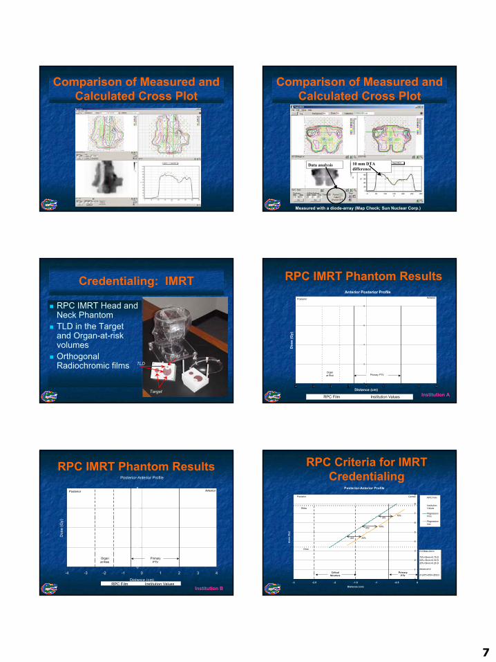
Comparison of Measured and Calculated Cross Plot
7
Comparison of Measured and Calculated Cross Plot
Comparison of Measured and Calculated Cross Plot
10 mm DTA difference
Data analysis
Measured with a diode-array (Map Check; Sun Nuclear Corp.)
Credentialing: IMRT
RPC IMRT Head and Neck PhantomTLD in the Target and Organ-at-risk volumesOrthogonal Radiochromic films
Target
Cord
TLD
Anterior Posterior Profile
0
2
4
6
8
-4 -3 -2 -1 0 1 2 3 4
Distance (cm)
Dos
e (G
y)
RPC Film Institution Values
Organat Risk
AnteriorPosterior
Primary PTV
RPC IMRT Phantom Results
Institution A
Posterior-Anterior Profile
0
2
4
6
8
-4 -3 -2 -1 0 1 2 3 4
Distance (cm)
Dos
e (G
y)
RPC Film Institution Values
Posterior Anterior
Organat Risk
PrimaryPTV
RPC IMRT Phantom Results
Institution B
Posterior-Anterior Profile
0
1
2
3
4
5
6
7
8
9
-3 -2.5 -2 -1.5 -1 -0.5 0Distance (cm)
dose
(Gy)
RPC Film
InstitutionValues
RegressionFilm
RegressionInst.
Posterior Central
PrimaryPTV
CriticalStructure
DMax
DminD=DMax-Dmin
75%=Dmin+0.75 D50%=Dmin+0.50 D25%=Dmin+0.25 D
distance=d
d=(d75+d50+d25)/3
75%
50%
25%
d75
d50
d25
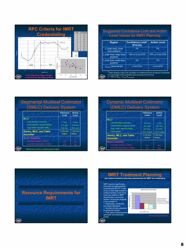
RPC Criteria for IMRT Credentialing
8
Posterior-Anterior Profile
0
1
2
3
4
5
6
7
8
9
-4 -3 -2 -1 0 1 2 3 4
Distance (cm)
Dose
(Gy)
RPC Film
InstitutionValues
Regression Film
Regression Inst.
PrimaryPTV
CriticalStructure
Posterior Anterior
7.36Gy+/-2%
2.49Gy+/-3%
RPC Criteria for IMRT Credentialing
Inst. Diff (mm)1 -1.32 2.03 -1.04 0.05 -3.36 -3.77 -2.38 0.09 -0.710 -4.0
0.50
1.00
1.50
-6.0 -4.0 -2.0 0.0 2.0 4.0
Plan - Film (mm)
TLD
(RP
C/In
st)
7% for Planning Target Volume4 mm DTA for the Organ-at-Risk
Suggested Confidence Limit and Action Level Values for IMRT Planning
3 mm DTA2 mm DTAδ90-50% (dose fall off)
7%4%δ1 (low dose, small dose gradient)
15% or 3 mm DTA10% or 2 mm DTAδ1 (high dose, large dose gradient)
5%3%δ1 (high dose, small dose gradient)
Action LevelConfidence Limit* (P=0.05)
Region
* Mean deviation used in the calculation of confidence limit for all regions is expressedAs a percentage of the prescribed dose according to the formula,δi = 100% X (Dcalc – Dmeas./D prescribed)
Segmental Multileaf Collimator (SMLC) Delivery System
3%3%
2%2%
Beam StabilityLow MU Output (<2MU)Low MU Symmetry (<2MU)
1.00 mm radius
0.75 mm radius
Gantry, MLC, and Table Isocenter
2 mm0.5 mm0.5 mm
1 mm0.2 mm0.2 mm
MLC*Leaf position accuracyLeaf position reproducibilityGap width reproducibility
Action Level
Tolerance Limit
* Measured at all four cardinal gantry angles
Dynamic Multileaf Collimator (DMLC) Delivery System
5%3%
3%2%
Beam StabilityLow MU Output (<2MU)Low MU Symmetry (<2MU)
1.00 mm radius
0.75 mm radius
Gantry, MLC, and Table Isocenter
1 mm0.5 mm0.5 mm
±0.2 mm/s
0.5 mm0.2 mm0.2 mm
±0.1 mm/s
MLC*Leaf position accuracyLeaf position reproducibilityGap width reproducibilityLeaf speed
Action Level
Tolerance Limit
Resource Requirements for IMRT
IMRT Treatment Planning(per patient treatment planning requirements for IMRT are challenging
Additional Planning Time/Patient
0
2
4
6
8
10
12
1
Type of IMRT Facility
Addi
tiona
l Hou
rs/IM
RT P
lan
800-bed AMC(2001)400-bed AMC(1998)600-bed Community(2001)300-bed Community(1999)
IMRT requires significantly more time for planning than conventional 3DCRT. It also turns out that large academic medical centers invest more hours per patient in IMRT planning than community centers. Driving the disparity is the variation in:
Initial goals, constraints and target definitions
Number of plans prepared for physician review
Time spent reviewing plans (physician and physicists, jointly)
Data from Oncology Roundtable
9
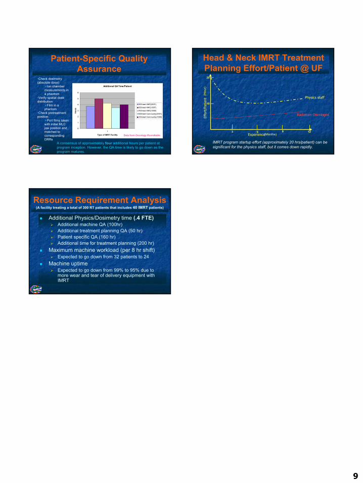
Patient-Specific Quality Assurance
Additional QA Time/Patient
0
1
2
3
4
5
6
1
Type of IMRT Facility
Hour
s
800-bed AMC(2001)600-bed AMC(1997)400-bed AMC(1998)600-bed Community(2001)300-bed Community(1999)
A consensus of approximately four additional hours per patient at program inception. However, the QA time is likely to go down as the program matures.
•Check dosimetry (absolute dose)
Ion chamber measurements in a phantom
•Verify spatial dose distribution
Film in a phantom
•Check pretreatment position
Port films taken with initial MLC jaw position and matched to correspondingDRRs
Data from Oncology Roundtable
Head & Neck IMRT Treatment Planning Effort/Patient @ UF
Experience
Physics staff
Radiation Oncologist
Effo
rt/P
atie
nt
IMRT program startup effort (approximately 20 hrs/patient) can be significant for the physics staff, but it comes down rapidly.
(Months)3 6 9 12
(Hou
r)
10
20
Resource Requirement Analysis(A facility treating a total of 300 RT patients that includes 40 IMRT patients)
Additional Physics/Dosimetry time (.4 FTE)Additional machine QA (100hr)Additional treatment planning QA (50 hr)Patient specific QA (160 hr)Additional time for treatment planning (200 hr)
Maximum machine workload (per 8 hr shift)Expected to go down from 32 patients to 24
Machine uptimeExpected to go down from 99% to 95% due to more wear and tear of delivery equipment with IMRT