Embed Size (px)
Citation preview
Tokamak plasma equilibria with a zero total toroidal currentYemin Hu Citation: Physics of Plasmas (1994-present) 15, 022505 (2008); doi: 10.1063/1.2839032 View online: http://dx.doi.org/10.1063/1.2839032 View Table of Contents: http://scitation.aip.org/content/aip/journal/pop/15/2?ver=pdfcov Published by the AIP Publishing Articles you may be interested in Toroidal current asymmetry in tokamak disruptions Phys. Plasmas 21, 102509 (2014); 10.1063/1.4898151 Topology of tokamak plasma equilibria with toroidal current reversal Phys. Plasmas 19, 012504 (2012); 10.1063/1.3662427 High-β equilibria in tokamaks with toroidal flow Phys. Plasmas 18, 092508 (2011); 10.1063/1.3641966 Analytical solutions for Tokamak equilibria with reversed toroidal current Phys. Plasmas 18, 082508 (2011); 10.1063/1.3624551 On tokamak equilibria with a zero current or negative current central region Phys. Plasmas 9, 5036 (2002); 10.1063/1.1521714
This article is copyrighted as indicated in the article. Reuse of AIP content is subject to the terms at: http://scitation.aip.org/termsconditions. Downloaded to IP:
84.88.136.149 On: Mon, 24 Nov 2014 07:59:23
Tokamak plasma equilibria with a zero total toroidal currentYemin HuInstitute of Plasma Physics, Chinese Academy of Sciences, Hefei, 230031, China
�Received 22 August 2007; accepted 9 January 2008; published online 26 February 2008�
Several tokamak experiments have reported the existence of plasma equilibria with a zero totaltoroidal current in the AC operations of tokamaks. By taking a toroidal current profile model as afunction of a quadratic polynomial of �, a variety of equilibrium configurations with a zero totaltoroidal current have been found by solving the Grad-Shafranov equation numerically in thecylindrical coordinate system for the arbitrary cross section and finite aspect ratio. Results fromdifferent parametrizations of the current density �pressure� profile are discussed. Using inputparameters consistent with experiments, some of the modeling results have been found to be in goodagreement with experiment observations. © 2008 American Institute of Physics.�DOI: 10.1063/1.2839032�
I. INTRODUCTION
AC operation experiments have been successfully con-ducted on several tokamaks such as Stor-1M,1,2 CT-6B,3,4
and HT-7,5 among others. The existence of current reversalequilibrium configurations �CRECs� when the total toroidalcurrent becomes zero has been demonstrated. Currently, alarge number of active theoretical investigations are beingmade to understand the behavior of CRECs.6–11 Martynovet al.9 have numerically investigated tokamak equilibriumsolutions with current density and poloidal field reversal, butthey only considered the force-free equilibria with zeroplasma pressure gradient and also assumed that the toroidalcurrent density is discontinuous. Wang et al.10–12 have pro-posed an analytical theoretical model for CRECs with finiteradial gradient of plasma pressure and continuous toroidalcurrent density, which may be more realistic than that of Ref.9. However, their work is limited to a linear current profilemodel with a few special cross-section cases such as a rect-angular cross section or a circular cross section with a largeaspect ratio. In this report, we extend the work of Wang et al.to more general current profiles model including nonlinearterms and more realistic cases with arbitrary cross sectionand aspect ratio by the numerical method.
We begin with the Grad-Shafranov equation of tokamakequilibrium with axisymmetric geometry �in which the toroi-dal angle � is an ignorable coordinate� in the plasma domain�,
�*� = −1
2�2d�
d�−
1
2
dg2
d�= − �j�, ��,z � �� , �1a�
where �*=x�� /�x��1 /x��� /�x�+�2 /�z2, �=� /B0a2 is thenormalized poloidal magnetic flux; x=R /a, z=Z /a, ����=2�0p��� /B0
2, g���=F��� /B0a, with magnetic field repre-
sented by B� =F�����+����; � is an ignorable angle inthe cylindrical coordinate system �R ,� ,Z�; p��� is theplasma pressure; B0 is the vacuum magnetic field evaluatedat R=R0�x=x0�; R0 and a are the major radius and the minorradius, respectively; j�=�0aJ� /B0, where J� is the toroidalcurrent density.
� and g2 in Eq. �1a� are general functions of �. Therepresentation of these two functions as a polynomial of � isone possibility. It necessarily makes the current density acontinuous function of � and we propose the current andpressure profile model as the following polynomial of �:
−1
2
d�
d�= a1 + a2� , �1b�
1
2
dg2
d�= b1 + b2� + b3�2. �1c�
We restrict it to a fixed boundary problem with ���b=0.From Eqs. �1b� and �1c�, we can obtain �=�0−2a1�−a2�2,j�=b1 /x−xa1+ �b2 /x−a2x��+b3 /x�2, and where �0 is cho-sen so that the minimum of plasma pressure is zero. In thefollowing tables and figures, if not specially claimed, allvariables are dimensionless quantities and the abscissas of allfigures are the normalized distance x.
To solve Eq. �1a�, five parameters ai, bj �i=1,2,j=1,2 ,3� must be prescribed. However, they are not realisticexperiment parameters; usually they can be determined by agroup of realistic physical quantities. In this report, for sim-plicity, we assume two of the coefficients are given arbi-trarily and that the other three are determined by the totaltoroidal current Ip, the current inside a finite region Ii, andthe normalized volume average plasma pressure �v. Here,
Ip =B0a
�0�
�
j�ds , �2a�
Ii =B0a
�0�
��j�ds ��� � �� , �2b�
�v =� �x�ds
� �xds. �2c�
We have used the finite element method and the Gauss-Newton iteration method to solve equation system Eq. �1a�and Eqs. �2a�–�2c�. The code is developed on the basis of theMATLAB language. Firstly, in order to illuminate the validity
PHYSICS OF PLASMAS 15, 022505 �2008�
1070-664X/2008/15�2�/022505/10/$23.00 © 2008 American Institute of Physics15, 022505-1
This article is copyrighted as indicated in the article. Reuse of AIP content is subject to the terms at: http://scitation.aip.org/termsconditions. Downloaded to IP:
84.88.136.149 On: Mon, 24 Nov 2014 07:59:23
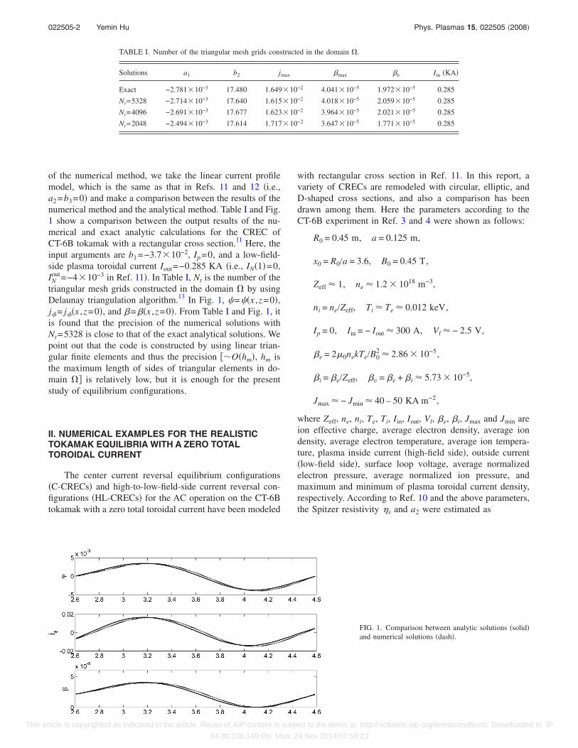
of the numerical method, we take the linear current profilemodel, which is the same as that in Refs. 11 and 12 �i.e.,a2=b3=0� and make a comparison between the results of thenumerical method and the analytical method. Table I and Fig.1 show a comparison between the output results of the nu-merical and exact analytic calculations for the CREC ofCT-6B tokamak with a rectangular cross section.11 Here, theinput arguments are b1=−3.710−2, Ip=0, and a low-field-side plasma toroidal current Iout=−0.285 KA �i.e., IN�1�=0,IN
out=−410−3 in Ref. 11�. In Table I, Nt is the number of thetriangular mesh grids constructed in the domain � by usingDelaunay triangulation algorithm.13 In Fig. 1, �=��x ,z=0�,j�= j��x ,z=0�, and �=��x ,z=0�. From Table I and Fig. 1, itis found that the precision of the numerical solutions withNt=5328 is close to that of the exact analytical solutions. Wepoint out that the code is constructed by using linear trian-gular finite elements and thus the precision ��O�hm�, hm isthe maximum length of sides of triangular elements in do-main �� is relatively low, but it is enough for the presentstudy of equilibrium configurations.
II. NUMERICAL EXAMPLES FOR THE REALISTICTOKAMAK EQUILIBRIA WITH A ZERO TOTALTOROIDAL CURRENT
The center current reversal equilibrium configurations�C-CRECs� and high-to-low-field-side current reversal con-figurations �HL-CRECs� for the AC operation on the CT-6Btokamak with a zero total toroidal current have been modeled
with rectangular cross section in Ref. 11. In this report, avariety of CRECs are remodeled with circular, elliptic, andD-shaped cross sections, and also a comparison has beendrawn among them. Here the parameters according to theCT-6B experiment in Ref. 3 and 4 were shown as follows:
R0 = 0.45 m, a = 0.125 m,
x0 = R0/a = 3.6, B0 = 0.45 T,
Zeff 1, ne 1.2 1018 m−3,
ni = ne/Zeff, Ti Te 0.012 keV,
Ip = 0, Iin = − Iout 300 A, Vl − 2.5 V,
�e = 2�0nekTe/B02 2.86 10−5,
�i = �e/Zeff, �v = �e + �i 5.73 10−5,
Jmax − Jmin 40 – 50 KA m−2,
where Zeff, ne, ni, Te, Ti, Iin, Iout, Vl, �e, �i, Jmax and Jmin areion effective charge, average electron density, average iondensity, average electron temperature, average ion tempera-ture, plasma inside current �high-field side�, outside current�low-field side�, surface loop voltage, average normalizedelectron pressure, average normalized ion pressure, andmaximum and minimum of plasma toroidal current density,respectively. According to Ref. 10 and the above parameters,the Spitzer resistivity s and a2 were estimated as
TABLE I. Number of the triangular mesh grids constructed in the domain �.
Solutions a1 b2 jmax �max �v Iin �KA�
Exact −2.78110−3 17.480 1.64910−2 4.04110−5 1.97210−5 0.285
Nt=5328 −2.71410−3 17.640 1.61510−2 4.01810−5 2.05910−5 0.285
Nt=4096 −2.69110−3 17.677 1.62310−2 3.96410−5 2.02110−5 0.285
Nt=2048 −2.49410−3 17.614 1.71710−2 3.64710−5 1.77110−5 0.285
FIG. 1. Comparison between analytic solutions �solid�and numerical solutions �dash�.
022505-2 Yemin Hu Phys. Plasmas 15, 022505 �2008�
This article is copyrighted as indicated in the article. Reuse of AIP content is subject to the terms at: http://scitation.aip.org/termsconditions. Downloaded to IP:
84.88.136.149 On: Mon, 24 Nov 2014 07:59:23
S = 1.65 10−9�Te−3/2 1.67 10−5 � m,
� 13.3 Te in keV,
b1 �0Vl
2�sB02 − 6.66 10−2,
where � is the classical Coulomb logarithm and �0 is mag-netic conductivity.
A. Linear pressure and current profile model„a2=0, b3=0…
In the following figures, Jm=J��x ,z=0� and �m=��x ,z=0�. a, b, and c represent the normalized magnetic flux �,the current density profile, and the normalized plasma pres-sure, respectively.
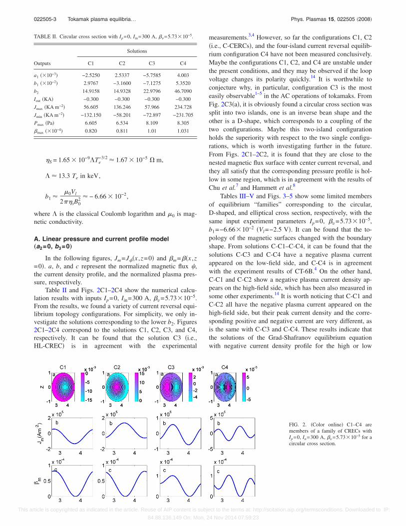
Table II and Figs. 2C1–2C4 show the numerical calcu-lation results with inputs Ip=0, Iin=300 A, �v=5.7310−5.From the results, we found a variety of current reversal equi-librium topology configurations. For simplicity, we only in-vestigate the solutions corresponding to the lower b2. Figures2C1–2C4 correspond to the solutions C1, C2, C3, and C4,respectively. It can be found that the solution C3 �i.e.,HL-CREC� is in agreement with the experimental
measurements.3,4 However, so far the configurations C1, C2�i.e., C-CERCs�, and the four-island current reversal equilib-rium configuration C4 have not been measured conclusively.Maybe the configurations C1, C2, and C4 are unstable underthe present conditions, and they may be observed if the loopvoltage changes its polarity quickly.14 It is worthwhile toconjecture why, in particular, configuration C3 is the mosteasily observable1–5 in the AC operations of tokamaks. FromFig. 2C3�a�, it is obviously found a circular cross section wassplit into two islands, one is an inverse bean shape and theother is a D-shape, which corresponds to a coupling of thetwo configurations. Maybe this two-island configurationholds the superiority with respect to the two single configu-rations, which is worth investigating further in the future.From Figs. 2C1–2C2, it is found that they are close to thenested magnetic flux surface with center current reversal, andthey all satisfy that the corresponding pressure profile is hol-low in some region, which is in agreement with the results ofChu et al.7 and Hammett et al.8
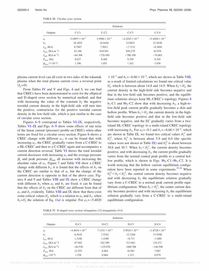
Tables III–V and Figs. 3–5 show some limited membersof equilibrium “families” corresponding to the circular,D-shaped, and elliptical cross section, respectively, with thesame input experiment parameters Ip=0, �v=5.7310−5,b1=−6.6610−2 �Vl=−2.5 V�. It can be found that the to-pology of the magnetic surfaces changed with the boundaryshape. From solutions C-C1–C-C4, it can be found that thesolutions C-C3 and C-C4 have a negative plasma currentappeared on the low-field side, and C-C4 is in agreementwith the experiment results of CT-6B.4 On the other hand,C-C1 and C-C2 show a negative plasma current density ap-pears on the high-field side, which has been also measured insome other experiments.14 It is worth noticing that C-C1 andC-C2 all have the negative plasma current appeared on thehigh-field side, but their peak current density and the corre-sponding positive and negative current are very different, asis the same with C-C3 and C-C4. These results indicate thatthe solutions of the Grad-Shafranov equilibrium equationwith negative current density profile for the high or low
FIG. 2. �Color online� C1–C4 aremembers of a family of CRECs withIp=0, In=300 A, �v=5.7310−5 for acircular cross section.
TABLE II. Circular cross section with Ip=0, Iin=300 A, � =5.7310−5.
Outputs
Solutions
C1 C2 C3 C4
a1 �10−3� −2.5250 2.5337 −5.7585 4.003
b1 �10−2� 2.9767 −3.1600 −7.1275 5.3520
b2 14.9158 14.9328 22.9796 46.7090
Iout �KA� −0.300 −0.300 −0.300 −0.300
Jmax �KA m−2� 56.605 136.246 57.966 234.728
Jmin �KA m−2� −132.150 −58.201 −72.897 −231.705
Pmax �Pa� 6.605 6.534 8.109 8.305
�max �10−4� 0.820 0.811 1.01 1.031
022505-3 Tokamak plasma equilibria… Phys. Plasmas 15, 022505 �2008�
This article is copyrighted as indicated in the article. Reuse of AIP content is subject to the terms at: http://scitation.aip.org/termsconditions. Downloaded to IP:
84.88.136.149 On: Mon, 24 Nov 2014 07:59:23
plasma current level can all exist in two sides of the tokamakplasma when the total plasma current cross a reversal point�Ip=0�.
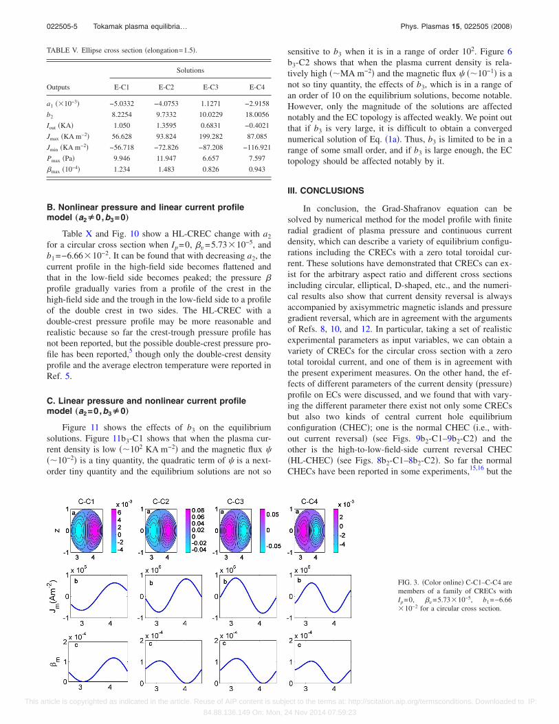
From Tables IV and V and Figs. 4 and 5, we can findthat CRECs have been demonstrated to exist for the ellipticaland D-shaped cross section by numerical method, and thatwith increasing the value of the constant b2 the negativetoroidal current density in the high-field side will turn intothe positive, contrariwise for the positive toroidal currentdensity in the low-field side, which is just similar to the caseof circular cross section.
Figures 6–9 correspond to Tables VI–IX, respectively.Tables VI–IX and Figs. 6–9 show some effects of one termof the linear current �pressure� profile on CRECs when otherterms are fixed for a circular cross section. Figure 6 shows aCREC change with different a1; it can be found that withincreasing a1, the CREC gradually varies from a C-CREC toa HL-CREC and then to a C-CREC again and accompanies acurrent direction reversal. Table VI shows the total toroidalcurrent decreases with increasing a1 and the average pressure�v and peak pressure �max all increase with increasing theabsolute value of a1. Figure 7 and Table VII show a CRECchange with different b1; it is found that the effects of b1 onthe CREC are similar to that of a1 but the change of thecurrent direction is opposite to that of the above case. Fig-ures 8 and 9 and Tables VIII and IX show a CREC changewith different b2 when a1 and b1 are fixed; it can be foundthat the effects of b2 on the CREC are different from that ofa1 and b1 evidently. Tables VIII and IX show that there existsome critical values b2
c, which is a relation to a1 and b1, whenb2=b2
c the solution of Eq. �1a� is singular. For a1=−5.4020
10−3 and b1=−6.6610−2, which are shown in Table VIII,as a result of limited calculations we found one critical valueb2
c, which is between about 14.8 and 14.9. When b2�b2c, the
current density in the high-field side becomes negative andthat in the low-field side becomes positive, and the equilib-rium solutions always keep HL-CREC’s topology. Figures 8b2-C1 and 8b2-C2 show that with decreasing b2, a high-to-low-field peak current profile gradually becomes a skin andhollow profile. When b2�b2
c, the current density in the high-field side becomes positive and that in the low-field sidebecomes negative, and the EC gradually varies from a two-island HL-CREC topology to a multi-island CREC topologywith increasing b2. For a1=−0.1 and b1=−6.6610−2, whichare shown in Table IX, we found two critical values b2
c1 andb2
c2, where b2c1 is between about 5.9 and 6.0 �the specific
values were not shown in Table IX� and b2c2 is about between
30.6 and 30.7. When b2�b2c1, the current density becomes
positive, and with decreasing b2, the current profile graduallyvaries from the normal central peak profile to a central hol-low profile, which is shown in Figs. 9b2-C1–9b2-C2. It isworth noticing that the hollow current equilibrium configu-ration have been reported in some experiments.15,16 Whenb2
c2�b2�b2c2, the central current density becomes negative
and with decreasing b2 the equilibrium solution graduallyvary from a C-CREC to a normal peak current profile equi-librium configuration. When b2�b2
c2, the center current den-sity becomes positive and with increasing b2 the equilibriumsolution gradually vary from a C-CREC to a multi-islandequilibrium configuration.
TABLE III. Circular cross section.
Outputs
Solutions
C-C1 C-C2 C-C3 C-C4
a1 −5.095710−3 3.950610−4 −4.224510−4 −5.402010−3
b2 10.1825 14.6444 15.0831 21.5630
Iout �KA� 0.7907 7.5012 −7.7132 −0.3694
Jmax �KA m−2� 63.186 818.951 856.279 63.076
Jmin �KA m−2� −64.308 −729.450 −780.190 −74.065
Pmax �Pa� 9.637 8.469 9.359 8.345
�max �10−4� 1.196 1.051 1.162 1.036
TABLE IV. D-shaped cross section �elongation=2.0, triangularity=0.4�.
Outputs
Solutions
D-C1 D-C2 D-C3 D-C4
a1 −4.463410−3 7.115110−4 5.591810−4 −1.872810−3
b2 6.5618 7.5142 12.1264 13.9398
Iout �KA� 1.2186 1.4180 −8.711 −1.000
Jmax �KA m−2� 67.942 242.289 513.841 119.271
Jmin �KA m−2� −46.530 −125.070 −600.708 −146.598
Pmax �Pa� 12.555 6.964 10.581 7.887
�max �10−4� 1.558 0.864 1.313 0.979
022505-4 Yemin Hu Phys. Plasmas 15, 022505 �2008�
This article is copyrighted as indicated in the article. Reuse of AIP content is subject to the terms at: http://scitation.aip.org/termsconditions. Downloaded to IP:
84.88.136.149 On: Mon, 24 Nov 2014 07:59:23
B. Nonlinear pressure and linear current profilemodel „a2Å0,b3=0…
Table X and Fig. 10 show a HL-CREC change with a2
for a circular cross section when Ip=0, �v=5.7310−5, andb1=−6.6610−2. It can be found that with decreasing a2, thecurrent profile in the high-field side becomes flattened andthat in the low-field side becomes peaked; the pressure �profile gradually varies from a profile of the crest in thehigh-field side and the trough in the low-field side to a profileof the double crest in two sides. The HL-CREC with adouble-crest pressure profile may be more reasonable andrealistic because so far the crest-trough pressure profile hasnot been reported, but the possible double-crest pressure pro-file has been reported,5 though only the double-crest densityprofile and the average electron temperature were reported inRef. 5.
C. Linear pressure and nonlinear current profilemodel „a2=0,b3Å0…
Figure 11 shows the effects of b3 on the equilibriumsolutions. Figure 11b3-C1 shows that when the plasma cur-rent density is low ��102 KA m−2� and the magnetic flux ���10−2� is a tiny quantity, the quadratic term of � is a next-order tiny quantity and the equilibrium solutions are not so
sensitive to b3 when it is in a range of order 102. Figure 6b3-C2 shows that when the plasma current density is rela-tively high ��MA m−2� and the magnetic flux � ��10−1� is anot so tiny quantity, the effects of b3, which is in a range ofan order of 10 on the equilibrium solutions, become notable.However, only the magnitude of the solutions are affectednotably and the EC topology is affected weakly. We point outthat if b3 is very large, it is difficult to obtain a convergednumerical solution of Eq. �1a�. Thus, b3 is limited to be in arange of some small order, and if b3 is large enough, the ECtopology should be affected notably by it.
III. CONCLUSIONS
In conclusion, the Grad-Shafranov equation can besolved by numerical method for the model profile with finiteradial gradient of plasma pressure and continuous currentdensity, which can describe a variety of equilibrium configu-rations including the CRECs with a zero total toroidal cur-rent. These solutions have demonstrated that CRECs can ex-ist for the arbitrary aspect ratio and different cross sectionsincluding circular, elliptical, D-shaped, etc., and the numeri-cal results also show that current density reversal is alwaysaccompanied by axisymmetric magnetic islands and pressuregradient reversal, which are in agreement with the argumentsof Refs. 8, 10, and 12. In particular, taking a set of realisticexperimental parameters as input variables, we can obtain avariety of CRECs for the circular cross section with a zerototal toroidal current, and one of them is in agreement withthe present experiment measures. On the other hand, the ef-fects of different parameters of the current density �pressure�profile on ECs were discussed, and we found that with vary-ing the different parameter there exist not only some CRECsbut also two kinds of central current hole equilibriumconfiguration �CHEC�; one is the normal CHEC �i.e., with-out current reversal� �see Figs. 9b2-C1–9b2-C2� and theother is the high-to-low-field-side current reversal CHEC�HL-CHEC� �see Figs. 8b2-C1–8b2-C2�. So far the normalCHECs have been reported in some experiments,15,16 but the
TABLE V. Ellipse cross section �elongation=1.5�.
Outputs
Solutions
E-C1 E-C2 E-C3 E-C4
a1 �10−3� −5.0332 −4.0753 1.1271 −2.9158
b2 8.2254 9.7332 10.0229 18.0056
Iout �KA� 1.050 1.3595 0.6831 −0.4021
Jmax �KA m−2� 56.628 93.824 199.282 87.085
Jmin �KA m−2� −56.718 −72.826 −87.208 −116.921
Pmax �Pa� 9.946 11.947 6.657 7.597
�max �10−4� 1.234 1.483 0.826 0.943
FIG. 3. �Color online� C-C1–C-C4 aremembers of a family of CRECs withIp=0, �v=5.7310−5, b1=−6.6610−2 for a circular cross section.
022505-5 Tokamak plasma equilibria… Phys. Plasmas 15, 022505 �2008�
This article is copyrighted as indicated in the article. Reuse of AIP content is subject to the terms at: http://scitation.aip.org/termsconditions. Downloaded to IP:
84.88.136.149 On: Mon, 24 Nov 2014 07:59:23
FIG. 4. �Color online� D-C1–D-C4 aremembers of a family of CRECs withIp=0, �v=5.7310−5, b1=−6.6610−2 for a D-shaped cross section.
FIG. 5. �Color online� E-C1–E-C4 aremembers of a family of CRECs withIp=0, �v=5.7310−5, b1=−6.6610−2 for an elliptical cross section.
FIG. 6. �Color online� EC changewith varying a1 when b1=−6.6610−2, b2=21.5649. a1-C1–a1-C7correspond to a1=−1, −0.1, −0.01,−5.402010−3 , −110−3 , 0 , 1.
022505-6 Yemin Hu Phys. Plasmas 15, 022505 �2008�
This article is copyrighted as indicated in the article. Reuse of AIP content is subject to the terms at: http://scitation.aip.org/termsconditions. Downloaded to IP:
84.88.136.149 On: Mon, 24 Nov 2014 07:59:23
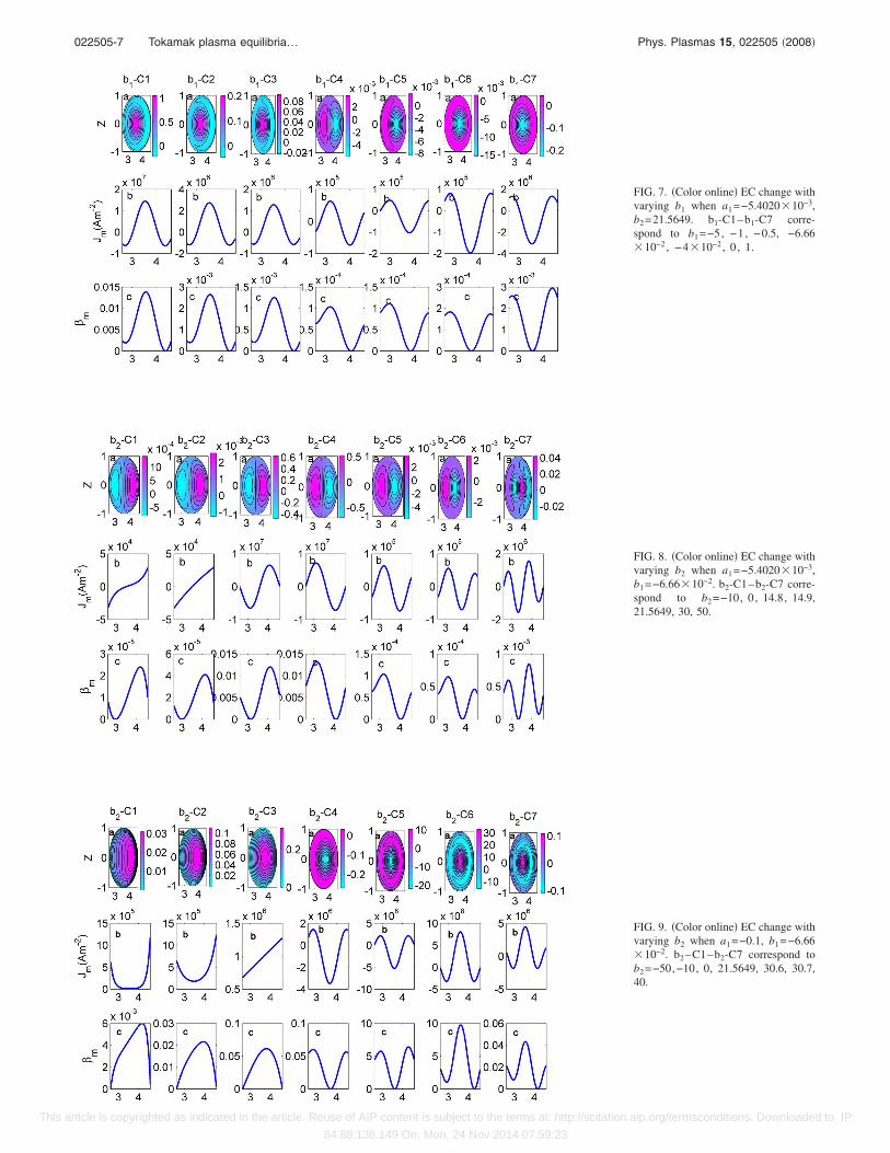
FIG. 7. �Color online� EC change withvarying b1 when a1=−5.402010−3,b2=21.5649. b1-C1–b1-C7 corre-spond to b1=−5, −1, −0.5, −6.6610−2 , −410−2 , 0 , 1.
FIG. 8. �Color online� EC change withvarying b2 when a1=−5.402010−3,b1=−6.6610−2. b2-C1–b2-C7 corre-spond to b2=−10, 0 , 14.8, 14.9,21.5649, 30, 50.
FIG. 9. �Color online� EC change withvarying b2 when a1=−0.1, b1=−6.6610−2. b2–C1–b2-C7 correspond tob2=−50,−10, 0, 21.5649, 30.6, 30.7,40.
022505-7 Tokamak plasma equilibria… Phys. Plasmas 15, 022505 �2008�
This article is copyrighted as indicated in the article. Reuse of AIP content is subject to the terms at: http://scitation.aip.org/termsconditions. Downloaded to IP:
84.88.136.149 On: Mon, 24 Nov 2014 07:59:23
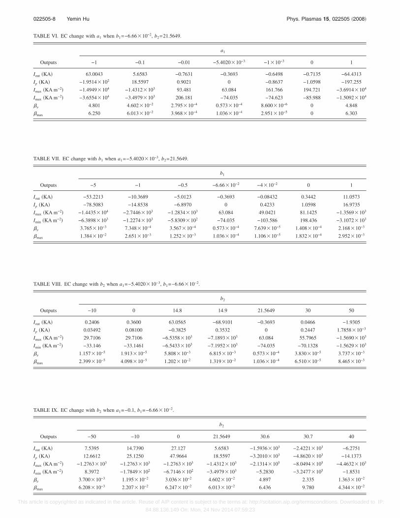
TABLE VI. EC change with a1 when b1=−6.6610−2, b2=21.5649.
Outputs
a1
−1 −0.1 −0.01 −5.402010−3 −110−3 0 1
Iout �KA� 63.0043 5.6583 −0.7631 −0.3693 −0.6498 −0.7135 −64.4313
Ip �KA� −1.9514102 18.5597 0.9021 0 −0.8637 −1.0598 −197.255
Imax �KA m−2� −1.4949104 −1.4312103 93.481 63.084 161.766 194.721 −3.6914104
Imax �KA m−2� −3.6554104 −3.4979103 206.181 −74.035 −74.623 −85.988 −1.5092104
�v 4.801 4.60210−2 2.79510−4 0.57310−4 8.60010−6 0 4.848
�max 6.250 6.01310−2 3.96810−4 1.03610−4 2.95110−5 0 6.303
TABLE VII. EC change with b1 when a1=−5.402010−3, b2=21.5649.
Outputs
b1
−5 −1 −0.5 −6.6610−2 −410−2 0 1
Iout �KA� −53.2213 −10.3689 −5.0123 −0.3693 −0.08432 0.3442 11.0573
Ip �KA� −78.5083 −14.8538 −6.8970 0 0.4233 1.0598 16.9735
Imax �KA m−2� −1.4435104 −2.7446103 −1.2834103 63.084 49.0421 81.1425 −1.3569103
Imin �KA m−2� −6.3898103 −1.2274103 −5.8309102 −74.035 −103.586 198.436 −3.1072103
�v 3.76510−3 7.34810−4 3.56710−4 0.57310−4 7.63910−5 1.40810−4 2.16810−3
�max 1.38410−2 2.65110−3 1.25210−3 1.03610−4 1.10610−5 1.83210−4 2.95210−3
TABLE VIII. EC change with b2 when a1=−5.402010−3, b1=−6.6610−2.
Outputs
b2
−10 0 14.8 14.9 21.5649 30 50
Iout �KA� 0.2406 0.3600 63.0565 −68.9101 −0.3693 0.0466 −1.9305
Ip �KA� 0.03492 0.08100 −0.3825 0.3532 0 0.2447 1.785810−3
Imax �KA m−2� 29.7106 29.7106 −6.5358103 −7.1893103 63.084 55.7965 −1.5690103
Imin �KA m−2� −33.146 −33.1461 −6.5433103 −7.1952103 −74.035 −70.1328 −1.5629103
�v 1.15710−5 1.91310−5 5.80810−3 6.81510−3 0.57310−4 3.83010−5 3.73710−3
�max 2.39910−5 4.09810−5 1.20210−2 1.31910−2 1.03610−4 6.51010−5 8.46510−3
TABLE IX. EC change with b2 when a1=−0.1, b1=−6.6610−2.
Outputs
b2
−50 −10 0 21.5649 30.6 30.7 40
Iout �KA� 7.5395 14.7390 27.127 5.6583 −1.5936103 −2.4221103 −6.2751
Ip �KA� 12.6612 25.1250 47.9664 18.5597 −3.2010103 −4.8620103 −14.1373
Imax �KA m−2� −1.2763103 −1.2763103 −1.2763103 −1.4312103 −2.1314105 −8.0494105 −4.4632103
Imin �KA m−2� 8.3972 −1.7849102 −6.7146102 −3.4979103 −5.2830 −3.2477105 −1.8531
�v 3.70010−3 1.19510−2 3.03610−2 4.60210−2 4.897 2.335 1.36310−2
�max 6.20810−3 2.20710−2 6.24710−2 6.01310−2 6.436 9.780 4.34410−2
022505-8 Yemin Hu Phys. Plasmas 15, 022505 �2008�
This article is copyrighted as indicated in the article. Reuse of AIP content is subject to the terms at: http://scitation.aip.org/termsconditions. Downloaded to IP:
84.88.136.149 On: Mon, 24 Nov 2014 07:59:23
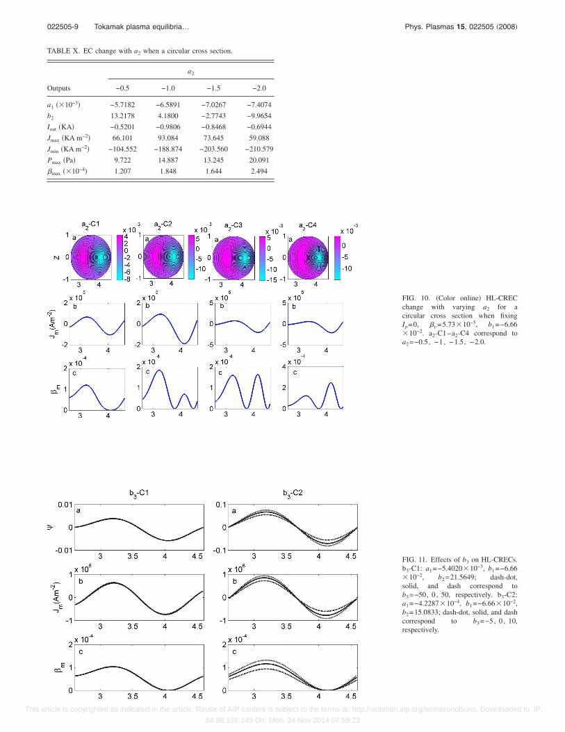
TABLE X. EC change with a2 when a circular cross section.
Outputs
a2
−0.5 −1.0 −1.5 −2.0
a1 �10−3� −5.7182 −6.5891 −7.0267 −7.4074
b2 13.2178 4.1800 −2.7743 −9.9654
Iout �KA� −0.5201 −0.9806 −0.8468 −0.6944
Jmax �KA m−2� 66.101 93.084 73.645 59.088
Jmin �KA m−2� −104.552 −188.874 −203.560 −210.579
Pmax �Pa� 9.722 14.887 13.245 20.091
�max �10−4� 1.207 1.848 1.644 2.494
FIG. 10. �Color online� HL-CRECchange with varying a2 for acircular cross section when fixingIp=0, �v=5.7310−5, b1=−6.6610−2. a2-C1–a2-C4 correspond toa2=−0.5, −1 , −1.5, −2.0.
FIG. 11. Effects of b3 on HL-CRECs.b3-C1: a1=−5.402010−3, b1=−6.6610−2, b2=21.5649; dash-dot,solid, and dash correspond tob3=−50, 0 , 50, respectively. b3-C2:a1=−4.228710−4, b1=−6.6610−2,b2=15.0833; dash-dot, solid, and dashcorrespond to b3=−5, 0 , 10,respectively.
022505-9 Tokamak plasma equilibria… Phys. Plasmas 15, 022505 �2008�
This article is copyrighted as indicated in the article. Reuse of AIP content is subject to the terms at: http://scitation.aip.org/termsconditions. Downloaded to IP:
84.88.136.149 On: Mon, 24 Nov 2014 07:59:23
HL-CRECs have not been reported yet, and we predict that itmay be possible for HL-CRECs to occur in the AC operationexperiments. It should be pointed out that this work is only apreliminary work; the physical details and the stability of theCRECs have not been investigated yet and they should beinvestigated in the future.
ACKNOWLEDGMENTS
This work was done partially during the author’s stay atNIFS. He wishes to thank Professor H. Sanuki for his hos-pitality and helpful discussion about this work. The authorthanks Professor B. Wan and Professor S. Wang for usefuldiscussions, and also thanks Professor G. Yu for reviewingthe entire paper.
This work is supported in part by the JSPS-CAS-University Program on Plasma and Nuclear Fusion.
1O. Mitarai, S. W. Wolfe, A. Hirose, and H. M. Skarsgard, Nucl. Fusion27, 604 �1987�.
2O. Mitarai, A. Hirose, and H. M. Skarsgard, Nucl. Fusion 32, 1801�1992�.
3X. Yang, D. Jiang, W. Li, G. Han, L. Wang, X. Qi, C. Feng, Z. Li, and S.Zheng, Nucl. Fusion 36, 1669 �1996�.
4J. Huang, X. Yang, S. Zheng, C. Feng, H. Zhang, and L. Wang, Nucl.Fusion 40, 2023 �2000�.
5J. Li, J. Luo, S. Wang et al., Nucl. Fusion 47, 1071 �2007�.6G. T. A. Huysmans, T. C. Hender, N. C. Hawkes, and X. Litaudon, Phys.Rev. Lett. 87, 245002 �2001�.
7M. S. Chu and P. B. Parks, Phys. Plasmas 9, 5036 �2002�.8G. W. Hammett, S. C. Jardin, and B. C. Stratton, Phys. Plasmas 10, 4048�2003�.
9A. A. Martynov, S. Yu. Medvedev, and L. Villard, Phys. Rev. Lett. 91,085004 �2003�.
10S. Wang and J. Yu, Phys. Plasmas 12, 062501 �2005�.11J. Yu, S. Wang, and J. Li, Phys. Plasmas 13, 054501 �2006�.12S. Wang, Phys. Rev. Lett. 93, 155007 �2004�.13Math Work. Using MATLAB, 2004.14S. Iizuka, Y. Minanitani, H. Tanaca, and Y. Kiwamoto, Phys. Rev. Lett.
53, 918 �1984�.15N. C. Hawkes, B. C. Stratton, T. Tala et al., Phys. Rev. Lett. 87, 115001
�2001�.16T. Fujit, T. Oikawa, T. Suzuki et al., Phys. Rev. Lett. 87, 245001 �2001�.
022505-10 Yemin Hu Phys. Plasmas 15, 022505 �2008�
This article is copyrighted as indicated in the article. Reuse of AIP content is subject to the terms at: http://scitation.aip.org/termsconditions. Downloaded to IP:
84.88.136.149 On: Mon, 24 Nov 2014 07:59:23