Embed Size (px)
Citation preview
MIPI D-PHY Protocol Fundamentals
Scope of this discussion
Mobile Computing
D-PHY Protocols
• D-PHY Layers
• Signaling and Traffic
• HS and LP Modes
• D-PHY States
• CSI and DSI idiosyncrasies
Early view of MIPI M-PHY
Demonstration of D-PHY Protocol Tools
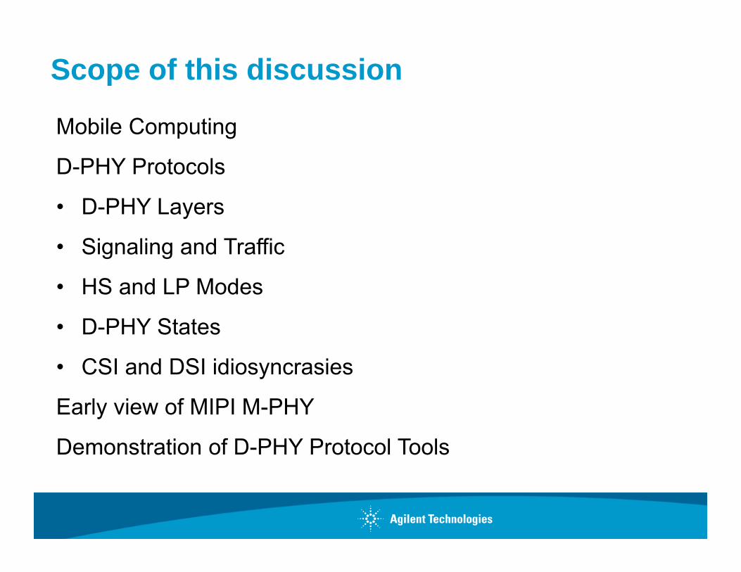
Demand is shifting from client /laptop devices to smart devices.
Meanwhile, laptop devices will start to look more like smart devices.
– PC demand is flattening and moving to mobile computing
“The cloud computing market is heading into the stratosphere as companies seek to offer services designed to serve tablets, smartphones and other mobile devices. … projected to surge to $110 billion in 2015, up from $23 billion in 2010.”iSuppli December 22, 2011
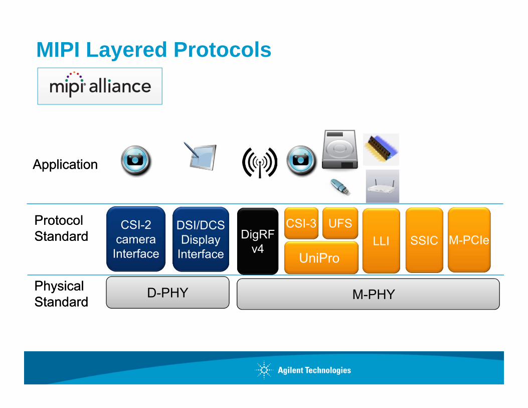
UniPro
UFS
PhysicalStandardPhysicalStandard
ProtocolStandardProtocolStandard
D-PHY
CSI-2cameraInterface
DSI/DCSDisplay
InterfaceDigRF
v4
M-PHY
ApplicationApplication
LLICSI-3
MIPI Layered Protocols
SSIC M-PCIe

PhysicalStandardPhysicalStandard
ProtocolStandardProtocolStandard
BIF
ApplicationApplication
MIPI Monolithic Protocols & Applications
Debug DDB HSI SLIMbus SPMIRFFE

About the MIPI Alliance
Coordinate technology across the mobile computing industry• Over 240 member companies
• 100% penetration of MIPI specs in smartphones by 2013
Develop specifications that ensure a stable, yet flexible technology ecosystem• 17 official working groups (14 active) and growing
• Partnerships with other industry organizations (JEDEC, USB-IF, Open Mobile Alliance, 3GPP, MEMS, etc.)
• Only members have access to specifications
• All members can participate and vote in discussions; higher levels of membership required to lead.

D-PHY layers (DSI example)
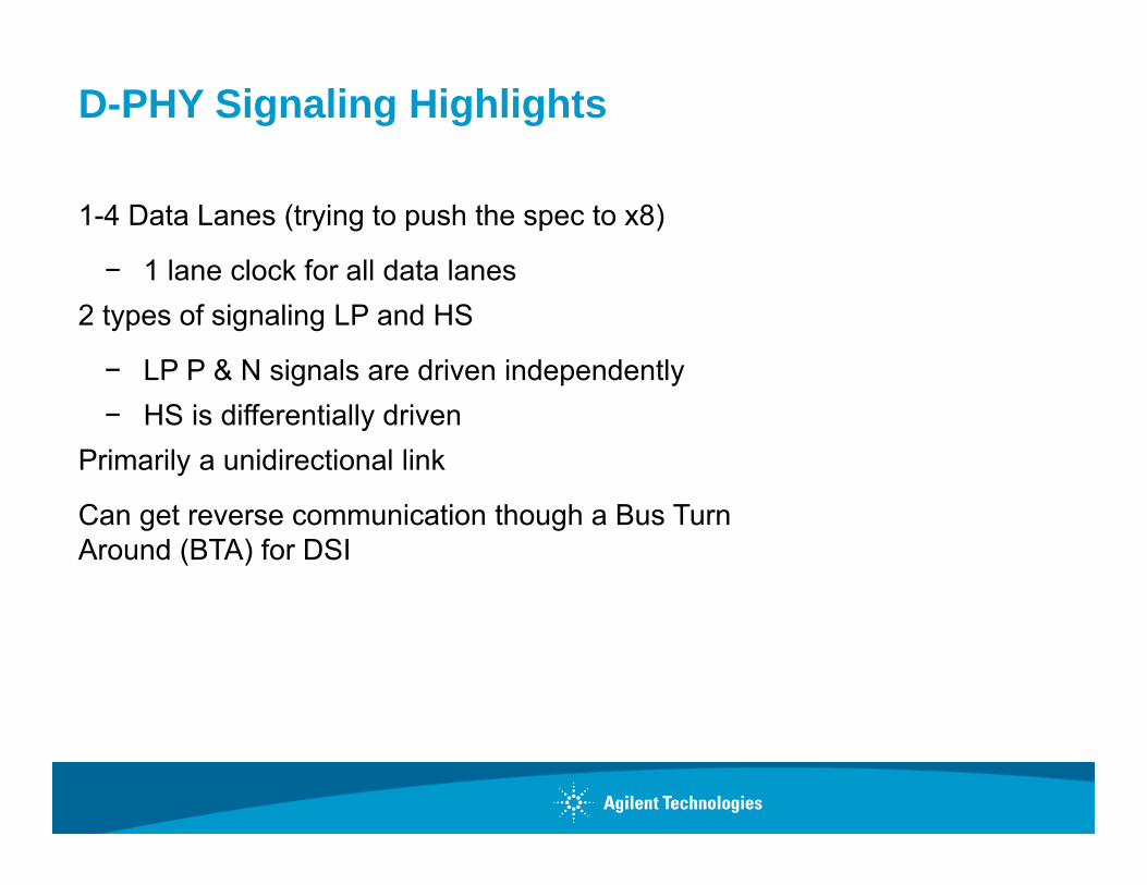
D-PHY Signaling Highlights
1-4 Data Lanes (trying to push the spec to x8)
− 1 lane clock for all data lanes2 types of signaling LP and HS
− LP P & N signals are driven independently− HS is differentially driven
Primarily a unidirectional link
Can get reverse communication though a Bus Turn Around (BTA) for DSI
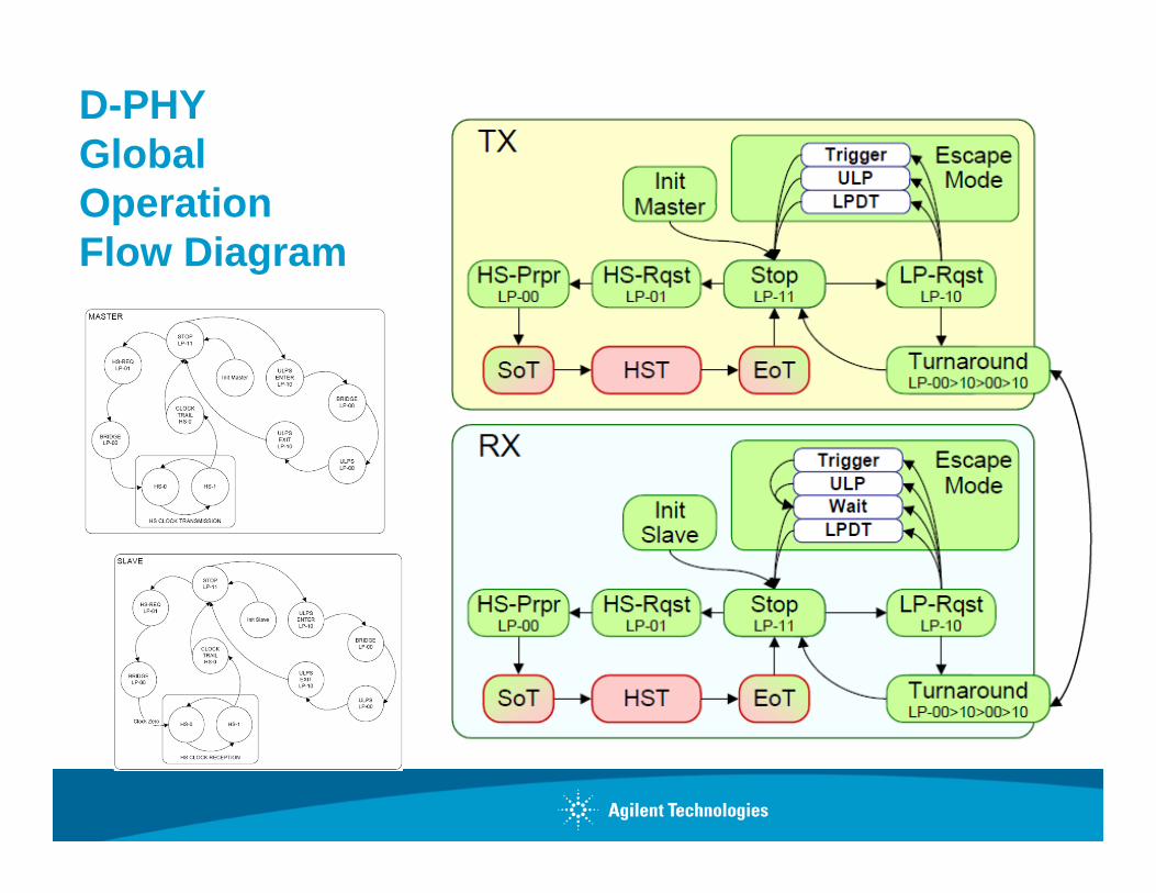
D-PHY Global Operation Flow Diagram

D-PHY Low Power SignalingLP Control
• 1.2V Nominal• Stop state LP-11• Escape Mode & HS Mode
Entry/Exit • Bus Turnaround (BTA), [DSI]
Escape Entry Codes
• Trigger/Modes (generic protocol messaging)
• Ultra Low Power (ULP – 78h)• Low Power Data Transmission
(LPDT – 87h)• Derived clock, 10Mbs max.
Binary opposites
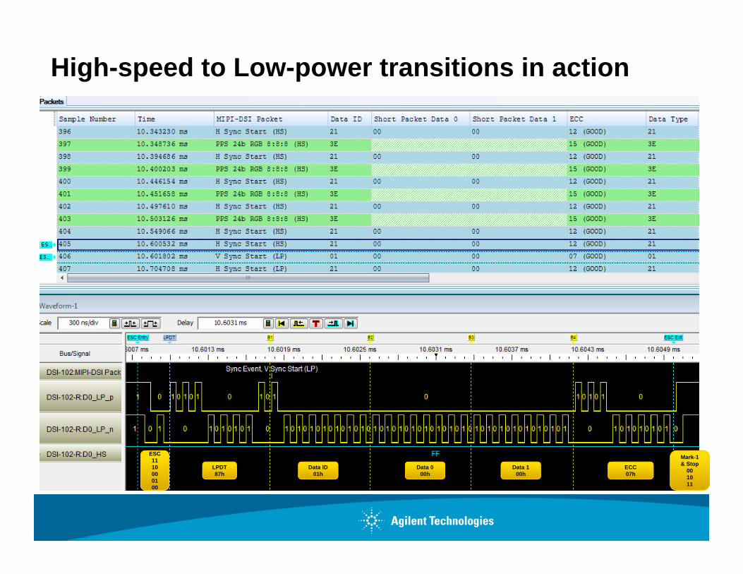
High-speed to Low-power transitions in action
ESC1110000100
LPDT87h
Data ID01h
Data 000h
Data 100h
ECC07h
Mark-1 & Stop
001011
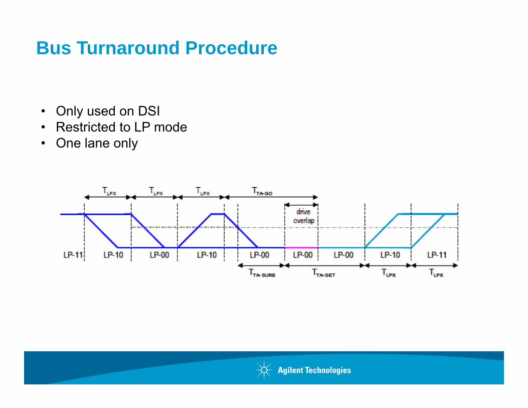
Bus Turnaround Procedure
• Only used on DSI• Restricted to LP mode• One lane only
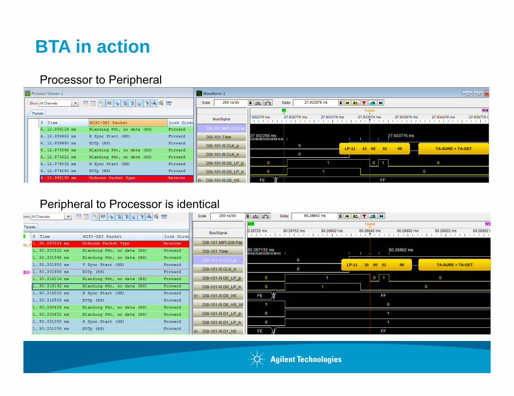
BTA in action
LP-11 10 00 01 00 TA-SURE + TA-GET
LP-11 10 00 01 00 TA-SURE + TA-GET
Processor to Peripheral
Peripheral to Processor is identical
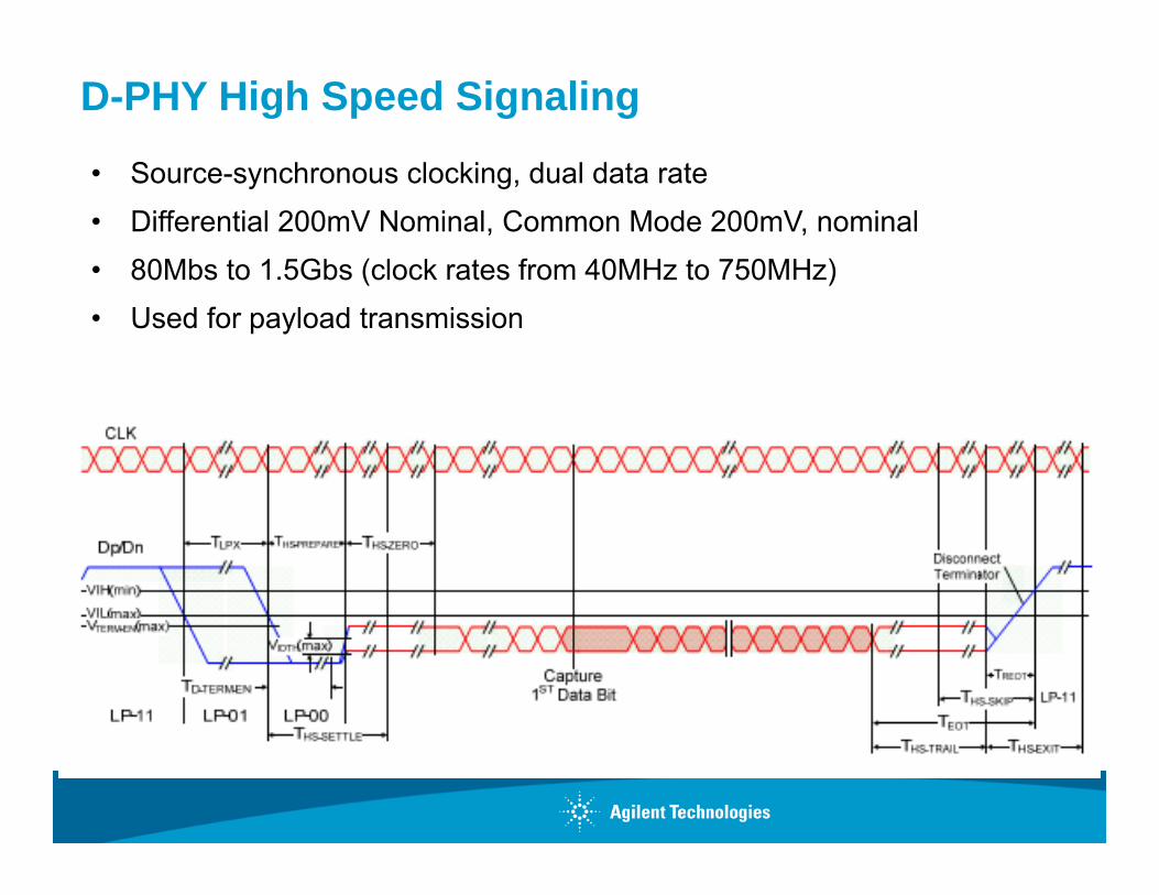
D-PHY High Speed Signaling
• Source-synchronous clocking, dual data rate• Differential 200mV Nominal, Common Mode 200mV, nominal• 80Mbs to 1.5Gbs (clock rates from 40MHz to 750MHz)• Used for payload transmission
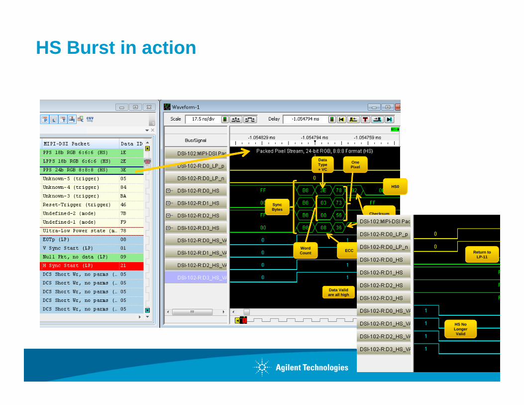
HS Burst in action
Data Valid are all high
Sync Bytes
Data Type + VC
Word Count
One Pixel
Checksum
ECC
HS0
HS No Longer Valid
Return to LP-11
ECC error correction (both short and long packets)
Error Correction Code (ECC) byte allows single-bit errors to be corrected and 2-bit errors to be detected in the Packet Header.
• Includes both the Data Identifier and Word Count fields
• Hamming Code• Detects 2-bit errors• Recovers 1-bit errors

Checksum (long packets only)
Payload portion of long packets
Functionality:
• 16-bit field (covers 64k payload)
• Can only indicate the presence of one or more errors in the payload.
• Cannot be used to correct errors.
Usage:
• Mandatory for processor to peripheral communication (DSI).
• Optional for peripheral to processor. If not used, “0000h” checksum must be sent.
• If the payload length is 0, checksum is “FFFFh”
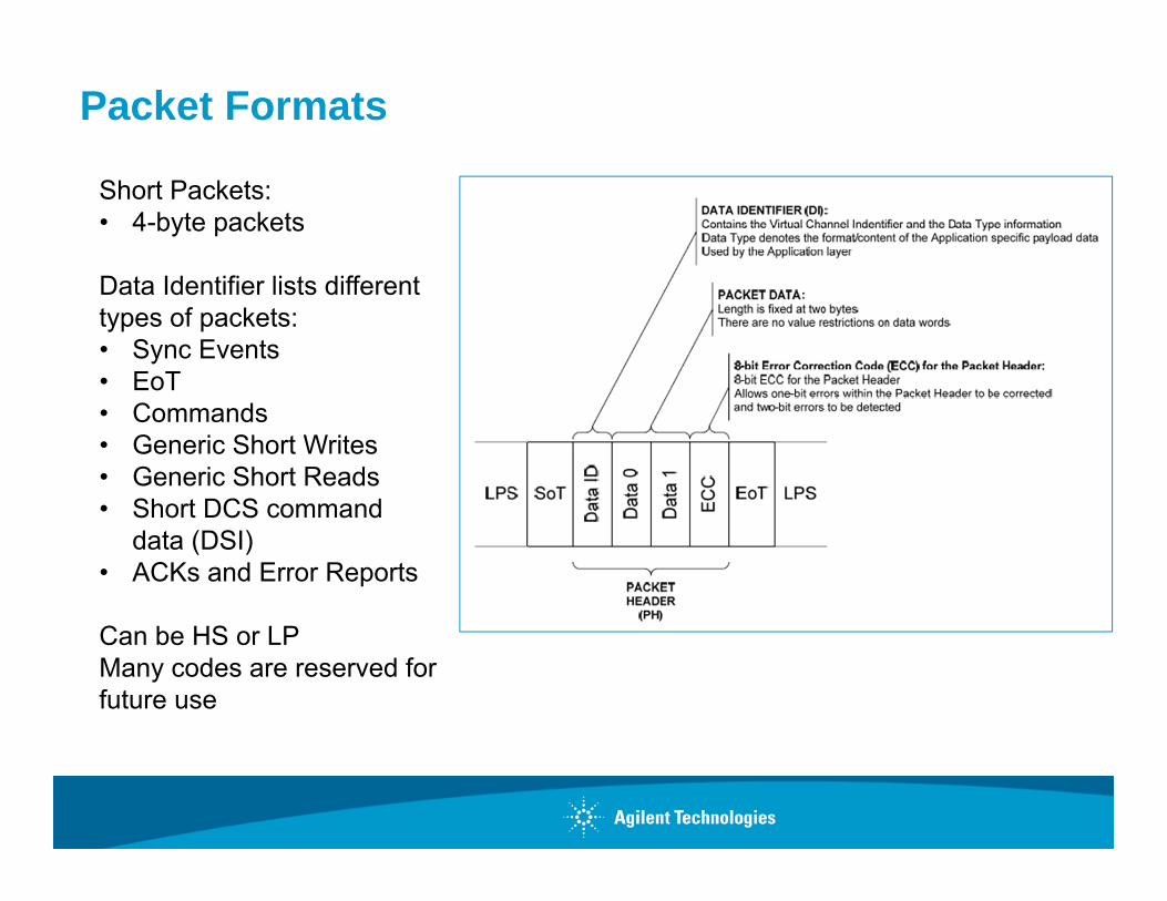
Packet Formats
Short Packets:• 4-byte packets
Data Identifier lists different types of packets:• Sync Events• EoT• Commands • Generic Short Writes• Generic Short Reads• Short DCS command
data (DSI)• ACKs and Error Reports
Can be HS or LPMany codes are reserved for future use
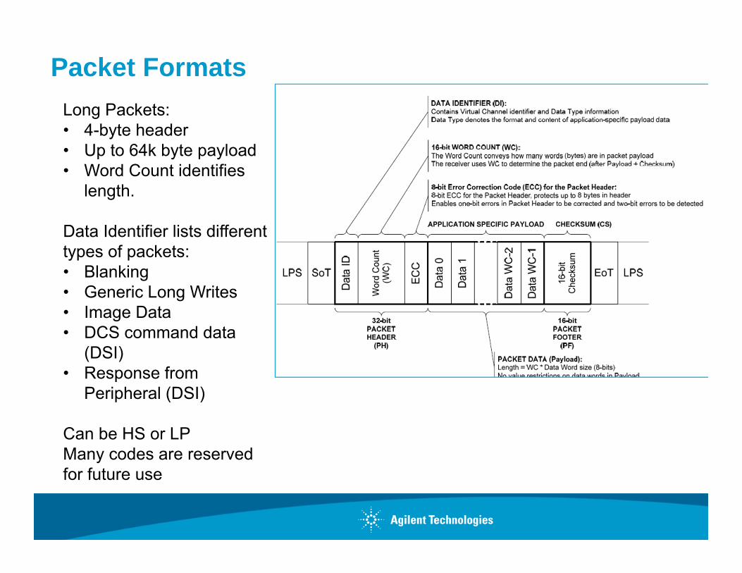
Packet FormatsLong Packets:• 4-byte header• Up to 64k byte payload• Word Count identifies
length.
Data Identifier lists different types of packets:• Blanking• Generic Long Writes• Image Data• DCS command data
(DSI)• Response from
Peripheral (DSI)
Can be HS or LPMany codes are reserved for future use

Example: DSI Packets
Data Type, hex
Data Type, binary Description Packet
Size
Data Type, hex
Data Type, binary Description Packet
Size
01h 00 0001 Sync Event, V Sync Start Short 24h 10 0100 Generic READ, 2 parameters Short
11h 01 0001 Sync Event, V Sync End Short 05h 00 0101 DCS WRITE, no parameters Short
21h 10 0001 Sync Event, H Sync Start Short 15h 01 0101 DCS WRITE, 1 parameter Short
31h 11 0001 Sync Event, H Sync End Short 06h 00 0110 DCS READ, no parameters Short
08h 00 1000 End of Transmission (EoT) packet Short 37h 11 0111 Set Maximum Return Packet Size Short
02h 00 0010 Color Mode (CM) Off Command Short 09h 00 1001 Null Packet, no data Long
12h 01 0010 Color Mode (CM) On Command Short 19h 01 1001 Blanking Packet, no data Long
22h 10 0010 Shut Down Peripheral Command Short 29h 10 1001 Generic Long Write Long
32h 11 0010 Turn On Peripheral Command Short 39h 11 1001 DCS Long Write/write_LUT Command Packet Long
03h 00 0011 Generic Short WRITE, no parameters Short 0Eh 00 1110
Packed Pixel Stream, 16-bit RGB, 5-6-5 Format Long
13h 01 0011 Generic Short WRITE, 1 parameter Short 1Eh 01 1110
Packed Pixel Stream, 18-bit RGB, 6-6-6 Format Long
23h 10 0011 Generic Short WRITE, 2 parameters Short 2Eh 10 1110
Loosely Packed Pixel Stream, 18-bit RGB, 6-6-6 Format Long
04h 00 0100 Generic READ, no parameters Short 3Eh 11 1110 Packed Pixel Stream, 24-bit RGB, 8-8-8 Format Long
14h 01 0100 Generic READ, 1 parameter Short
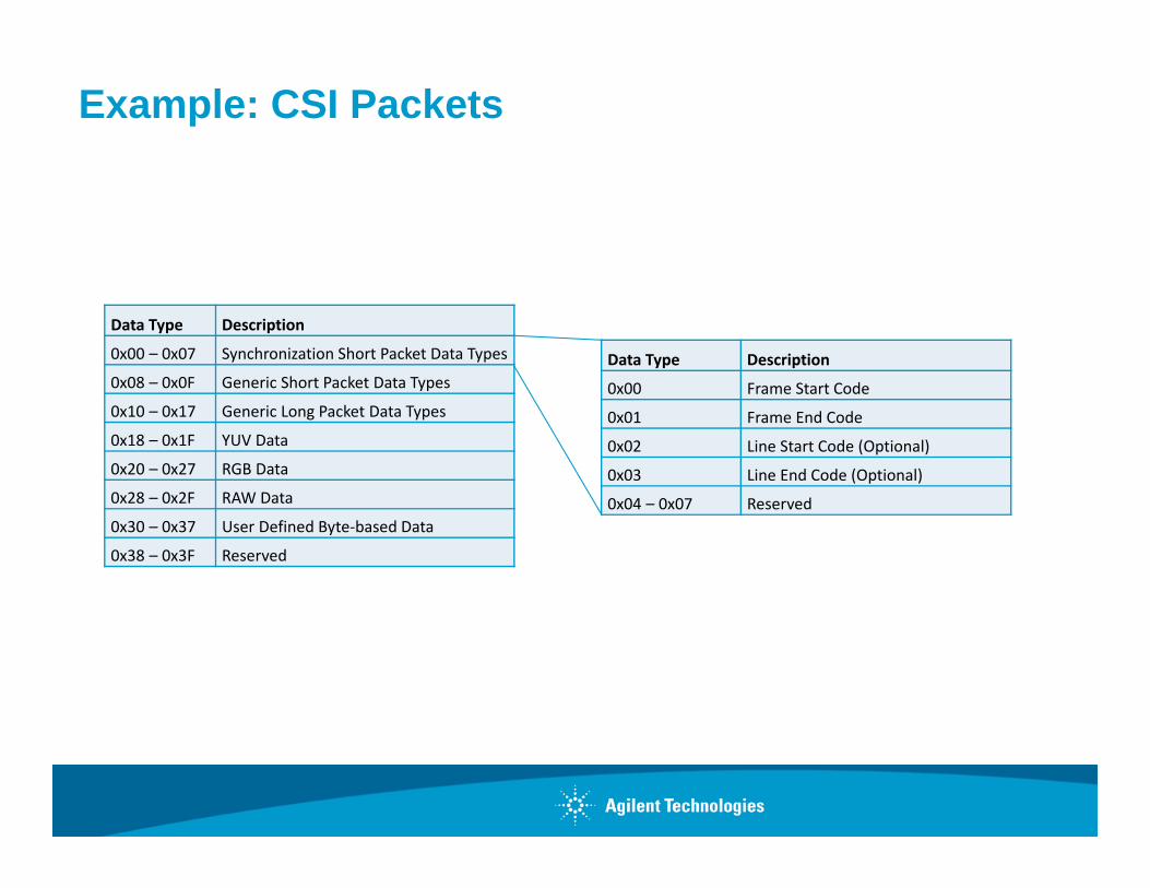
Example: CSI Packets
Data Type Description
0x00 – 0x07 Synchronization Short Packet Data Types
0x08 – 0x0F Generic Short Packet Data Types
0x10 – 0x17 Generic Long Packet Data Types
0x18 – 0x1F YUV Data
0x20 – 0x27 RGB Data
0x28 – 0x2F RAW Data
0x30 – 0x37 User Defined Byte‐based Data
0x38 – 0x3F Reserved
Data Type Description
0x00 Frame Start Code
0x01 Frame End Code
0x02 Line Start Code (Optional)
0x03 Line End Code (Optional)
0x04 – 0x07 Reserved
CSI-2 ParticularsCCI – Camera Control Interface
• I2C subset used to configure camera interface (instead of BTA)– CCI is the protocol layer– Multiple-devices, single controller
• No BTAOnly HS transmissions
Simple Low-Level Protocol packet formats
• Long – for transmitting Application Specific Payload data• Short– for transmitting Frame and Line synchronization data, and other image-related
parameters.
Virtual Channel – independent data stream for one of up to four peripherals
1 packet per HS frame
• Frame Start/ Frame End
• Optional Line Start/ Line End
• LP State between frames

DSI Particulars
LPDT (on D0 only)
Low-power burst
Greater variety of packet types
• Short packets
• Long packets
• Processor commands (BTA)
• Great variety of image traffic– Burst (asynchronous)– Non-burst (synchronous, with and without sync events)– Display commands
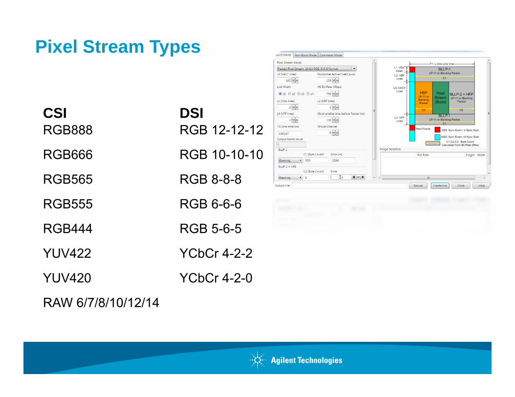
Pixel Stream Types
CSIRGB888
RGB666
RGB565
RGB555
RGB444
YUV422
YUV420
RAW 6/7/8/10/12/14
DSIRGB 12-12-12
RGB 10-10-10
RGB 8-8-8
RGB 6-6-6
RGB 5-6-5
YCbCr 4-2-2
YCbCr 4-2-0
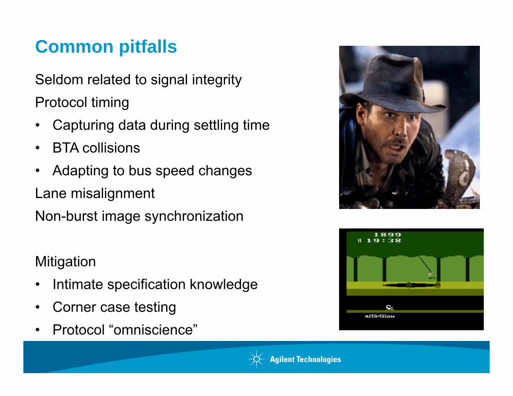
Common pitfalls
Seldom related to signal integrityProtocol timing• Capturing data during settling time• BTA collisions • Adapting to bus speed changesLane misalignmentNon-burst image synchronization
Mitigation• Intimate specification knowledge• Corner case testing• Protocol “omniscience”
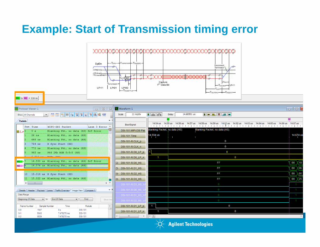
Example: Start of Transmission timing error
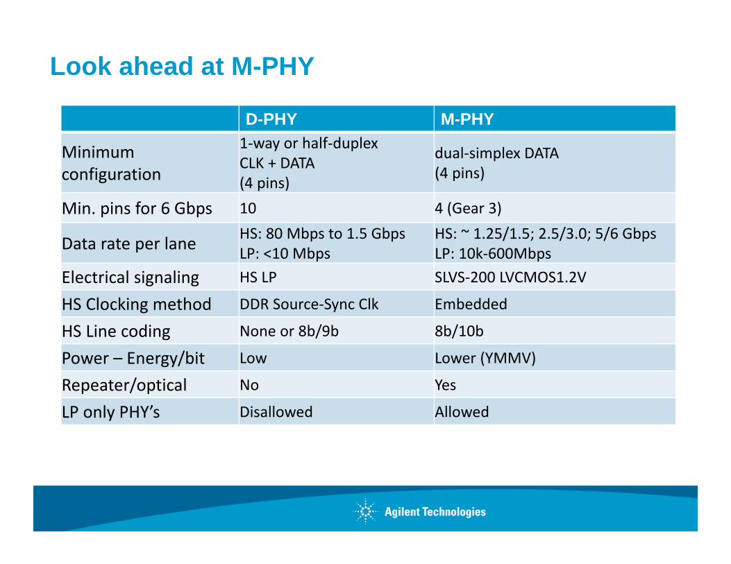
Look ahead at M-PHY
D-PHY M-PHY
Minimum configuration
1‐way or half‐duplex CLK + DATA (4 pins)
dual‐simplex DATA (4 pins)
Min. pins for 6 Gbps 10 4 (Gear 3)
Data rate per lane HS: 80 Mbps to 1.5 GbpsLP: <10 Mbps
HS: ~ 1.25/1.5; 2.5/3.0; 5/6 GbpsLP: 10k‐600Mbps
Electrical signaling HS LP SLVS‐200 LVCMOS1.2V
HS Clocking method DDR Source‐Sync Clk Embedded
HS Line coding None or 8b/9b 8b/10b
Power – Energy/bit Low Lower (YMMV)
Repeater/optical No Yes
LP only PHY’s Disallowed Allowed
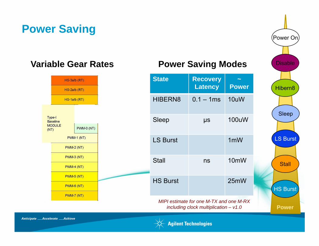
Power Saving
Variable Gear Rates Power Saving ModesState Recovery
Latency~
Power
HIBERN8 0.1 – 1ms 10uW
Sleep µs 100uW
LS Burst 1mW
Stall ns 10mW
HS Burst 25mW
MIPI estimate for one M-TX and one M-RX including clock multiplication – v1.0
HS Burst
Stall
LS Burst
Sleep
Hibern8
Disable
Power On
Power
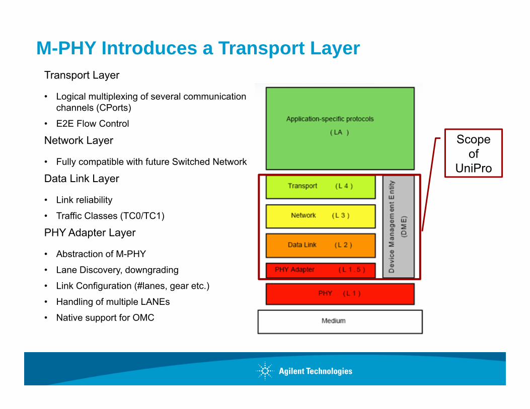
M-PHY Introduces a Transport LayerTransport Layer
• Logical multiplexing of several communication channels (CPorts)
• E2E Flow Control
Network Layer
• Fully compatible with future Switched Network
Data Link Layer
• Link reliability
• Traffic Classes (TC0/TC1)
PHY Adapter Layer
• Abstraction of M-PHY
• Lane Discovery, downgrading
• Link Configuration (#lanes, gear etc.)
• Handling of multiple LANEs
• Native support for OMC
Scope of
UniPro