Embed Size (px)
Citation preview

TodMaster Reference Manual 1.0 Page 1 of 48
TodMasterClock
Reference Manual
Product Info
Product Manager Sven Meier
Author(s) Sven Meier
Reviewer(s) -
Version 1.0
Date 18.03.2017

TodMaster Reference Manual 1.0 Page 2 of 48
Copyright Notice
Copyright © 2016 NetTimeLogic GmbH, Switzerland. All rights reserved.
Unauthorized duplication of this document, in whole or in part, by any means, is
prohibited without the prior written permission of NetTimeLogic GmbH, Switzer-
land.
All referenced registered marks and trademarks are the property of their respective
owners
Disclaimer
The information available to you in this document/code may contain errors and is
subject to periods of interruption. While NetTimeLogic GmbH does its best to
maintain the information it offers in the document/code, it cannot be held respon-
sible for any errors, defects, lost profits, or other consequential damages arising
from the use of this document/code.
NETTIMELOGIC GMBH PROVIDES THE INFORMATION, SERVICES AND PROD-
UCTS AVAILABLE IN THIS DOCUMENT/CODE "AS IS," WITH NO WARRANTIES
WHATSOEVER. ALL EXPRESS WARRANTIES AND ALL IMPLIED WARRANTIES,
INCLUDING WARRANTIES OF MERCHANTABILITY AND FITNESS FOR A PARTIC-
ULAR PURPOSE, AND NON-INFRINGEMENT OF PROPRIETARY RIGHTS ARE
HEREBY DISCLAIMED TO THE FULLEST EXTENT PERMITTED BY LAW. IN NO
EVENT SHALL NETTIMELOGIC GMBH BE LIABLE FOR ANY DIRECT, INDIRECT,
INCIDENTAL, CONSEQUENTIAL, SPECIAL AND EXEMPLARY DAMAGES, OR ANY
DAMAGES WHATSOEVER, ARISING FROM THE USE OR PERFORMANCE OF THIS
DOCUMENT/CODE OR FROM ANY INFORMATION, SERVICES OR PRODUCTS
PROVIDED THROUGH THIS DOCUMENT/CODE, EVEN IF NETTIMELOGIC GMBH
HAS BEEN ADVISED OF THE POSSIBILITY OF SUCH DAMAGES.
IF YOU ARE DISSATISFIED WITH THIS DOCUMENT/CODE, OR ANY PORTION
THEREOF, YOUR EXCLUSIVE REMEDY SHALL BE TO CEASE USING THE DOCU-
MENT/CODE.

TodMaster Reference Manual 1.0 Page 3 of 48
Overview
NetTimeLogic’s Time Of Day (TOD) Master Clock is a full hardware (FPGA) only
implementation of a synchronization core able to synchronize a Time of Day sink
via NMEA over UART.
The whole message creation, algorithms and calculations are implemented in the
core, no CPU is required. This allows running TOD synchronization completely
independent and standalone from the user application. The core can be configured
either by signals or by an AXI4Light-Slave Register interface.
This core only uses the second part of the clock, frequency and sub-second offset
distribution shall be done in a combination with the PPS Master Clock.
Key Features:
• Time of Day Master Clock
• Built-in UART transmitter with configurable baudrate
• NMEA message creator
• Support for NMEA GPZDA messages for time distribution
• Hardware time conversion from seconds since midnight 1.1.1970 (Linux, TAI,
PTP) intoTime of Day format (hh:mm:ss dd:mm:yyyy)
• Sending at the local second overflow
• In combination with a PPS Master Clock from NetTimeLogic: synchronization
accuracy: +/- 25ns
• AXI4 Light register set or static configuration

TodMaster Reference Manual 1.0 Page 4 of 48
Revision History
This table shows the revision history of this document.
Version Date Revision
0.1 10.02.2017 First draft
1.0 18.03.2017 First release
Table 1: Revision History

TodMaster Reference Manual 1.0 Page 5 of 48
Content
1 INTRODUCTION 9
1.1 Context Overview 9
1.2 Function 10
1.3 Architecture 10
2 NMEA BASICS 12
2.1 Interface 12
2.2 Messages 12
2.2.1 ZDA – Data and Time 12
2.3 Message rate and phase 13
2.4 UTC vs TAI time bases 13
3 REGISTER SET 15
3.1 Register Overview 15
3.2 Register Descriptions 16
3.2.1 General 16
4 DESIGN DESCRIPTION 23
4.1 Top Level – Tod Master 23
4.2 Design Parts 30
4.2.1 TX Processor 30
4.2.2 UART Interface Adapter 33
4.2.3 Registerset 35
4.3 Configuration example 39
4.3.1 Static Configuration 39
4.3.2 AXI Configuration 39
4.4 Clocking and Reset Concept 40

TodMaster Reference Manual 1.0 Page 6 of 48
4.4.1 Clocking 40
4.4.2 Reset 40
5 RESOURCE USAGE 42
5.1 Altera (Cyclone V) 42
5.2 Xilinx (Artix 7) 42
6 DELIVERY STRUCTURE 43
7 TESTBENCH 44
7.1 Run Testbench 44
8 REFERENCE DESIGNS 45
8.1 Altera: Terasic SocKit 45
8.2 Xilinx: Digilent Arty 46

TodMaster Reference Manual 1.0 Page 7 of 48
Definitions
Definitions
NMEA 0183
Is a combined electrical and data specification for commu-
nication between marine electronics such as echo sounder,
sonars, anemometer, gyrocompass, autopilot, GPS receiv-
ers and many other types of instruments. The NMEA 0183
standard uses a simple ASCII, serial communications proto-
col that defines how data are transmitted in a "sentence"
from one "talker" to multiple "listeners" at a time
Tod Master Clock A clock that can synchronize other vis NMEA 0183 mes-
sages via UART
PI Servo Loop Proportional–integral servo loop, allows for smooth correc-
tions
Offset Phase difference between clocks
Drift Frequency difference between clocks
Table 2: Definitions
Abbreviations
Abbreviations
AXI AMBA4 Specification (Stream and Memory Mapped)
IRQ Interrupt, Signaling to e.g. a CPU
PPS Pulse Per Second
TOD Time of Day
TM TOD Master
GPS Global Positioning System
NMEA National Marine Electronics Association
TS Timestamp
TB Testbench
UART/RS232 Universal Asynchronous Receiver Transmitter
LUT Look Up Table

TodMaster Reference Manual 1.0 Page 8 of 48
FF Flip Flop
RAM Random Access Memory
ROM Read Only Memory
FPGA Field Programmable Gate Array
VHDL Hardware description Language for FPGA’s
UTC Coordinated Universal Time, popularly known as GMT
(Greenwich Mean Time)
TAI
Temps Atomique International, is the international atomic
time scale based on a continuous counting of the SI sec-
ond. TAI is currently ahead of UTC by 36 seconds. TAI is
always ahead of GPS by 19 seconds.
Table 3: Abbreviations

TodMaster Reference Manual 1.0 Page 9 of 48
1 Introduction
1.1 Context Overview
The TOD Master Clock is meant as a co-processor handling Time of Day (TOD)
outputs in the form of NMEA messages via UART. It transmits NMEA messages to a
NMEA sink (IED receiver) via an UART/RS232 interface; it does not receive any
message from the sink though.
This means it creates NMEA messages directly in hardware, converts the time from
the same format and time base as the Counter Clock into the Time of Day formar
and sends it via UART.
The TOD Master Clock is designed to work in cooperation with the Counter Clock
core from NetTimeLogic (not a requirement). It can be combined with a PPS Mas-
ter clock to synchronize for e.g. an IED receiver. Offset and drift are then distribut-
ed via the PPS Master Clock to the next second and the TOD Master Clock will
distribute the absolute time on seconds level.
It contains an AXI4Light slave for configuration and supervision from a CPU, this is
however not required since the TOD Master Clock can also be configured statically
via signals/constants directly from within the FPGA.
UART TX TodMasterClockTodMasterClockNMEA
Sink(IED
receiver)
CLOCKAdjustable Clock
Time
AX
I4 L
ite
Slav
e
CPU
AXI4L
Figure 1: Context Block Diagram

TodMaster Reference Manual 1.0 Page 10 of 48
1.2 Function
The TOD Master Clock first converts the local time in seconds since midnight
1.1.1970 (no fractions of seconds used) together with a configurable offset to con-
vert between TAI and UTC or any other time base (leap seconds or different start
of epoch) to time in the hh:mm:ss dd:mm:yyyy format taking leap years into ac-
count and passes it at the next second boundary to the NMEA message creator.
This Time of Day is converted from binary UTC time into ASCII encoded time and is
then embedded into a NMEA GPZDA messages with the local time information
provided and sent via an AXI byte stream to the UART output. The UART converts
the AXI byte stream to an UART output with configurable baud rate.
1.3 Architecture
The core is split up into different functional blocks for reduction of the complexity,
modularity and maximum reuse of blocks. The interfaces between the functional
blocks are kept as small as possible for easier understanding of the core.
UART
AXI4 Lite Slave
REGISTERSET
TodMasterClockTodMasterClock
CLOCKAdjustable Clock
AXI
4 Li
te S
lave
NMEA(IED
Receiver)
NMEACREATOR
UARTTX
AXIS
TIME CONV
Time of Day
Time
Figure 2: Architecture Block Diagram

TodMaster Reference Manual 1.0 Page 11 of 48
Register Set
This block allows reading status values and writing configuration.
UART Transmitter
This block is an UART Transmitter which converts the byte aligned AXI stream into
a serial stream.
NMEA Crator
This block creates the NMEA message, embeds the UTC time in time of day format
and adds the local time and sends it as a data stream to the UART Transmitter
Time Converter
This block converts the TAI time in seconds since 1.1.1970 without leap seconds
format into UTC time in time of day format.

TodMaster Reference Manual 1.0 Page 12 of 48
2 NMEA Basics
2.1 Interface
NMEA 0183 is a standard for communication between navigation equipment on
ships defined by the National Marine Electronics Association which also defines
how the communication between a GPS receiver and a PC shall look like.
The NMEA 0183 standard uses a simple ASCII, serial communications protocol that
defines how data are transmitted in messages from one source to multiple sinks at
a time.
Typical Baud rate 4800
Data bits 8
Parity None
Stop bits 1
Handshake None
2.2 Messages
NMEA messages always start with a “$” character, followed by the source id which
is “GP” for GPS (or also this core), followed by a three character message type.
Then a message type dependent number of fields of different lengths follow, each
field separated with a “,” character. The last field is terminated with a “*” character
and followed by a checksum in hexadecimal format.
There are many message types defined for GPS sources, however only a few con-
tain the time of day: ZDA (Data and Time) and RMC (Recommended Minimum
Data).
The message format of the ZDA message used is described in the next chapters,
be aware that some GPS receiver have higher accuracy on some values and will
add fractions, so fields don’t always have the same width (e.g. seconds might be
with or without fractions).
2.2.1 ZDA – Data and Time
This message is specifically made for transferring time. It event has the local time
offset for local time but this is not used.

TodMaster Reference Manual 1.0 Page 13 of 48
$GPZDA,hhmmss.ss,dd,mm,yyyy,aa,bb*CC
• hh: hours (00 - 23)
• mm: minutes (00 - 59)
• ss.ss: decimal seconds (00.99 - 60.99)
• dd: day (01 – 31)
• mm: month (01 – 12)
• yyyy: year (1970 – 2106)
• aa: local zone hours (-13 - 13)
• bb: local zone minutes (00 - 59)
• *CC: checksum (00-FF)
2.3 Message rate and phase
The message rates of these message shall is set to once per second. It is important
that the received NMEA message is received in a fixed phase to the second over-
flow (PPS) e.g. always at the second overflow other ways time jumps can happen.
PPS from CLK
NMEA from CLK
Figure 3: NMEA to PPS alignment
2.4 UTC vs TAI time bases
The message contains the time of day on UTC base. UTC has an offset to TAI which
is the time base normally used for the Counter Clock. This time offset can be set in
the core so the local clock can still run on a TAI base. UTC in comparison to TAI or
GPS time has so called leap seconds. A leap second is an additional second which
is either added or subtracted from the current time to adjust for the earth rotation
variation over time. Until 2016 UTC had additional 36 leap seconds, therefore TAI
time is currently 36 seconds ahead of UTC. The issue with UTC time is, that the
time makes jumps with the leap seconds which may cause that synchronized nodes
go out of sync for a couple of seconds. Leap seconds are normally introduced at

TodMaster Reference Manual 1.0 Page 14 of 48
midnight of either the 30 of June or 31 of December. For an additional leap second
the seconds counter of the UTC time will count to 60 before wrapping around to
zero, for one fewer leap second the UTC second counter will wrap directly from 58
to 0 by skipping 59 (this has not happened yet).
Be aware that this core takes no additional precautions to handle leap seconds, so
it will make a time jump at a UTC leap second and will cause that the sinks lose
synchronization since it thinks that it has an offset of one second at tries to distrib-
ute this offset. A way to avoid this is to disable the distribution at the two dates
right before midnight (e.g. one minute earlier), wait for the leap second to happen,
fetch some time server to get the new offset between TAI and UTC, set this offset
to the core and enable the core again. This way the distributed clock on UTC base
makes no jump at the wrong second since the new offset is already taken into
account. The only issue with this is that for the time around midnight the sinks are
free running without a reference.
TodMaster Reference Manual 1.0 Page 15 of 48
3 Register Set
This is the register set of the TOD Master Clock. It is accessible via AXI4 Light Memory Mapped. All registers are 32bit wide, no
burst access, no unaligned access, no byte enables, no timeouts are supported. Register address space is not contiguous. Register
addresses are only offsets in the memory area where the core is mapped in the AXI inter connects. Non existing register access in
the mapped memory area is answered with a slave decoding error.
3.1 Register Overview
Registerset Overview
Name Description Offset Access
Tod MasterControl Reg Tod Master Enable Control Register 0x00000000 RW
Tod MasterStatus Reg Tod Master Error Status Register 0x00000004 WC
Tod MasterVersionReg Tod Master Version Register 0x00000004 WC
Tod MasterCorrection Reg Tod Master Second Corrections Register 0x00000010 RW
Tod MasterLocal Reg Tod Master Local Time Register 0x00000014 RW
Tod MasterUartBaudRate Reg Tod Master UART Baud Rate Register 0x00000020 RW
Table 4: Register Set Overview

TodMaster Reference Manual 1.0 Page 16 of 48
3.2 Register Descriptions
3.2.1 General
3.2.1.1 TOD Master Control Register
Used for general control over the TOD Master Clock, all configurations on the core shall only be done when disabled.
Tod MasterControl Reg
Reg Description
31 30 29 28 27 26 25 24 23 22 21 20 19 18 17 16 15 14 13 12 11 10 9 8 7 6 5 4 3 2 1 0
-
EN
AB
LE
RO RW
Reset: 0x00000000
Offset: 0x0000
Name Description Bits Access
- Reserved, read 0 Bit:31:1 RO
ENABLE Enable Bit: 0 RW

TodMaster Reference Manual 1.0 Page 17 of 48
3.2.1.2 TOD Master Status Register
Shows the current status of the TOD Master Clock.
Tod MasterStatus Reg
Reg Description
31 30 29 28 27 26 25 24 23 22 21 20 19 18 17 16 15 14 13 12 11 10 9 8 7 6 5 4 3 2 1 0
-
ER
RO
R
RO WC
Reset: 0x00000000
Offset: 0x0004
Name Description Bits Access
- Reserved, read 0 Bit:31:1 RO
ENABLE Error (sticky) Bit: 0 WC

TodMaster Reference Manual 1.0 Page 18 of 48
3.2.1.3 TOD Master Version Register
Version of the IP core, even though is seen as a 32bit value, bits 31 down to 24 represent the major, bits 23 down to 16 the minor
and bits 15 down to 0 the build numbers.
Tod MasterVersion Reg
Reg Description
31 30 29 28 27 26 25 24 23 22 21 20 19 18 17 16 15 14 13 12 11 10 9 8 7 6 5 4 3 2 1 0
VE
RS
ION
RO
0xXXXXXXXX
Offset: 0x000C
Name Description Bits Access
VERSION Version of the core Bit: 31:0 RO

TodMaster Reference Manual 1.0 Page 19 of 48
3.2.1.4 TOD Master Correction Register
Correction register to compensate for leap seconds between the different time domains. NMEA is UTC time, all other time in the
system is TAI, this leads to a correction of 36 seconds by 2016.
Tod MasterCorrection Reg
Reg Description
31 30 29 28 27 26 25 24 23 22 21 20 19 18 17 16 15 14 13 12 11 10 9 8 7 6 5 4 3 2 1 0
CO
R_
SIG
N
CO
R_
S
RW RW
Reset: 0x00000000
Offset: 0x0010
Name Description Bits Access
COR_SIGN Correction sign Bit: 31 RW
COR_S Correction in seconds to the time extracted from the NMEA => used to convert between TAI, UTC and GPS (leap sec-onds)
Bit: 30:0 RW

TodMaster Reference Manual 1.0 Page 20 of 48
3.2.1.5 TOD Master Local Register
Local Time register to distribute also local time: from -13:59 to 13:59. Hours and Minutes for local time can be set as well as the sign
which is valid for both values.
Tod MasterCorrection Reg
Reg Description
31 30 29 28 27 26 25 24 23 22 21 20 19 18 17 16 15 14 13 12 11 10 9 8 7 6 5 4 3 2 1 0
LO
CA
L_
SIG
N
-
LO
CA
L_
H
-
LO
CA
L_
M
RW RO RW RO RW
Reset: 0x00000000
Offset: 0x0014
Name Description Bits Access
LOCAL_SIGN Local time offset sign Bit: 31 RW
- Reserved, read 0 Bit: 30:20 RO
LOCAL_H Local time offset hours, 0-13 Bit: 19:16 RW
- Reserved, read 0 Bit: 15:6 RO
LOCAL_M Local time offset minutes 0-59 Bit: 5:0 RW

TodMaster Reference Manual 1.0 Page 21 of 48
3.2.1.6 TOD Master UART Baud Rate Register
This set the receive baud rate of the UART. The baud rate can only be changed when the core is disabled. Otherwise the changes
have no effect. Only the most common baud rates are available from a range of 1.2k to 2m baud.
Tod MasterUartBaudRate Reg
Reg Description
31 30 29 28 27 26 25 24 23 22 21 20 19 18 17 16 15 14 13 12 11 10 9 8 7 6 5 4 3 2 1 0
-
BA
UD
_R
AT
E
RO RW
Reset: 0x0000000X
Offset: 0x0020
Name Description Bits Access
- Reserved, read 0 Bit: 31:4 RO

TodMaster Reference Manual 1.0 Page 22 of 48
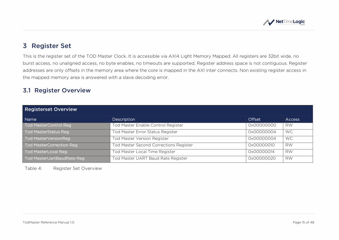
BAUD_RATE Encoded Baudrate of the UART receiver: 0 => 1200 1 => 2400 2 => 4800 3 => 9600 4 => 19200 5 => 38400 6 => 57600 7 => 115200 8 => 230400 9 => 460800 10 => 921600 11 => 1000000 12 => 2000000 >12 => not allowed undefinded Default can be set by generic
Bit: 3:0 RW

TodMaster Reference Manual 1.0 Page 23 of 48
4 Design Description
The following chapters describe the internals of the TOD Master Clock: starting
with the Top Level, which is a collection of subcores, followed by the description of
all subcores.
4.1 Top Level – Tod Master
4.1.1.1 Parameters
The core must be parametrized at synthesis time. There are a couple of parameters
which define the final behavior and resource usage of the core.
Name Type Size Description
GpZdaMessage
Support_Gen boolean 1
Support for GPZDA Messages:
true = supported, false = not
supported (only true is sup-
ported at the moment since
this is the only message type
allowed)
StaticConfig_Gen boolean 1
If Static Configuration or AXI
is used:
true = Static, false = AXI
NmeaCorrection_Gen natural 1
NMEA correction in seconds
for when the message is sent
to the next second overflow.
There are some sinks which
expect the NMEA of the next
second and some of the
current. Default is the next,
then correction of 1 is needed
ClockClkPeriod
Nanosecond_Gen natural 1
Clock Period in Nanosecond:
Default for 50 MHz = 20 ns
UartBaudRate_Gen natural 1
Default Baudrate encoded:
0 => 1200
1 => 2400
2 => 4800
3 => 9600
TodMaster Reference Manual 1.0 Page 24 of 48
4 => 19200
5 => 38400
6 => 57600
7 => 115200
8 => 230400
9 => 460800
10 => 921600
11 => 1000000
12 => 2000000
AxiAddressRang
Low_Gen std_logic_vector 32
AXI Base Address
AxiAddressRange
High_Gen std_logic_vector 32
AXI Base Address plus Regis-
terset Size
Default plus 0xFFFF
Sim_Gen boolean 1
If in Testbench simulation
mode:
true = Simulation, false =
Synthesis
Table 5: Parameters
One of the two parameters GpZdaMessageSupport_Gen and GpZdaMessageSup-
port_Gen has to be true.
4.1.1.2 Structured Types
4.1.1.2.1 Clk_Time_Type
Defined in Clk_Package.vhd of library ClkLib
Type represents the time used everywhere. For this type overloaded operators +
and – with different parameters exist.
Field Name Type Size Description
Second std_logic_vector 32 Seconds of time
Nanosecond std_logic_vector 32 Nanoseconds of time
Fraction std_logic_vector 2 Fraction numerator (mostly
not used)
Sign std_logic 1 Positive or negative time, 1 =
negative, 0 = positive.

TodMaster Reference Manual 1.0 Page 25 of 48
TimeJump std_logic 1 Marks when the clock makes a
time jump (mostly not used)
Table 6: Clk_Time_Type
4.1.1.2.2 Tod_MasterStaticConfig_Type
Defined in Tod_MasterAddrPackage.vhd of library TodLib
This is the type used for static configuration.
Field Name Type Size Description
Correction Clk_Time_Type 1
Time to correct the parsed
time to correct UTC to TAI or
another base.
LocalSign
std_logic 1
Sign off the local time:
0 => positive
1 => negative
LocalHour std_logic_vector 4 Local time hours part: 0 -13
LocalMinute std_logic_vector 6 Local time minutes part: 0 - 59
UartBaudRate std_logic_vector 4
Baudrate encoded:
0 => 1200
1 => 2400
2 => 4800
3 => 9600
4 => 19200
5 => 38400
6 => 57600
7 => 115200
8 => 230400
9 => 460800
10 => 921600
11 => 1000000
12 => 2000000
Table 7: Tod_MasterStaticConfig_Type
4.1.1.2.3 Tod_MasterStaticConfigVal_Type
Defined in Tod_MasterAddrPackage.vhd of library TodLib
This is the type used for valid flags of the static configuration.

TodMaster Reference Manual 1.0 Page 26 of 48
Field Name Type Size Description
Enable_Val std_logic 1 Enables the TOD Master
Table 8: Tod_MasterStaticConfigVal_Type
4.1.1.3 Entity Block Diagram
UART
UARTITF
ADAPTER
REGISTERSETAXI MM
Config
AXIS
Error
TXPROC.
Enable
Time
Correction & Local Time
BaudRate
Figure 4: TOD Master Clock
4.1.1.4 Entity Description
Tx Processor
This module handles all outgoing NMEA message. It converts the time from sec-
onds since 1.1.1970 format into Time of Day taking offset and leap years into ac-
count, embeds the UTC time and local time into a GPZDA message and sends it to
the UART interface adapter.
See 4.2.1 for more details.
UART Interface Adapter
This module converts the AXI stream to a serial UART signal. It handles the RS232
protocol data stream with one start, eight data, one stop and no parity. AXI stream
to this module is 8 bit width. It can handle baud rates from 9.6k up to 1m.
See 4.2.2 for more details.
Registerset
This module is an AXI Light Memory Mapped Slave. It provides access to all regis-
ters and allows configuring the TOD Master Clock. It can be configured to either
run in AXI or StaticConfig mode. If in StaticConfig mode, the configuration of the
registers is done via signals and can be easily done from within the FPGA without
CPU. If in AXI mode, an AXI Master has to configure the Datasets with AXI writes to
the registers, which is typically done by a CPU

TodMaster Reference Manual 1.0 Page 27 of 48
See 4.2.3 for more details.
4.1.1.5 Entity Declaration
Name Dir Type Size Description
Generics
General
GpZdaMessage
Support_Gen - boolean 1
Support for GPZDA
Messages (must be
true)
StaticConfig_Gen - boolean 1 If Static Configura-
tion or AXI is used
NmeaCorrection_Gen - natural 1
NMEA correction in
seconds for when
the message arrive
to the next second
overflow.
ClockClkPeriod
Nanosecond_Gen - natural 1
Clock Period in
Nanosecond
UartBaudRate_Gen - natural 1
Default Baudrate
encoded:
0 => 1200
1 => 2400
2 => 4800
3 => 9600
4 => 19200
5 => 38400
6 => 57600
7 => 115200
8 => 230400
9 => 460800
10 => 921600
11 => 1000000
12 => 2000000
AxiAddressRang
Low_Gen - std_logic_vector 32
AXI Base Address
AxiAddressRange
High_Gen - std_logic_vector 32
AXI Base Address
plus Registerset

TodMaster Reference Manual 1.0 Page 28 of 48
Size
Sim_Gen - boolean 1 If in Testbench
simulation mode
Ports
System SysClk_ClkIn in std_logic 1 System Clock
SysRstN_RstIn in std_logic 1 System Reset
Config
StaticConfig_DatIn in Tod_Master
StaticConfig_Type 1
Static Configuration
StaticConfig_ValIn in
Tod_Master
StaticConfigVal
_Type
1
Static Configuration
valid
Timer
Timer1ms_EvtIn in std_logic 1
Millisecond timer
adjusted with the
Clock
Time Input
ClockTime_DatIn in Clk_Time_Type 1 Adjusted Clock
Time
ClockTime_ValIn in std_logic 1 Adjusted Clock
Time valid
AXI4 Light Slave AxiWriteAddrValid _ValIn
in std_logic 1 Write Address Valid
AxiWriteAddrReady _RdyOut
out std_logic 1 Write Address
Ready
AxiWriteAddrAddress _AdrIn
in std_logic_vector 32 Write Address
AxiWriteAddrProt _DatIn
in std_logic_vector 3 Write Address
Protocol
AxiWriteDataValid _ValIn
in std_logic 1 Write Data Valid
AxiWriteDataReady _RdyOut
out std_logic 1 Write Data Ready
AxiWriteDataData _DatIn
in std_logic_vector 32 Write Data
AxiWriteDataStrobe _DatIn
in std_logic_vector 4 Write Data Strobe
AxiWriteRespValid _ValOut
out std_logic 1 Write Response
Valid
AxiWriteRespReady _RdyIn
in std_logic 1 Write Response
Ready

TodMaster Reference Manual 1.0 Page 29 of 48
AxiWriteResp Response_DatOut
out std_logic_vector 2 Write Response
AxiReadAddrValid _ValIn
in std_logic 1 Read Address Valid
AxiReadAddrReady _RdyOut
out std_logic 1 Read Address
Ready
AxiReadAddrAddress _AdrIn
in std_logic_vector 32 Read Address
AxiReadAddrProt _DatIn
in std_logic_vector 3 Read Address
Protocol
AxiReadDataValid _ValOut
out std_logic 1 Read Data Valid
AxiReadDataReady _RdyIn
in std_logic 1 Read Data Ready
AxiReadData Response_DatOut
out std_logic_vector 2 Read Data
AxiReadDataData _DatOut
out std_logic_vector 32 Read Data Re-
sponse
Time of Day Output
Uart_DatOut out std_logic 1 UART to the NMEA
sink
Table 9: TOD Master Clock

TodMaster Reference Manual 1.0 Page 30 of 48
4.2 Design Parts
The TOD Master Clock core consists of a couple of subcores. Each of the subcores
itself consist again of smaller function block. The following chapters describe these
subcores and their functionality.
4.2.1 TX Processor
4.2.1.1 Entity Block Diagram
AXISNMEA
CREATOR
TIME CONV
Time of Day
Time
Local Time
Error
Enable
Correction
Figure 5: TX Processor
4.2.1.2 Entity Description
NMEA Creator
This module convertes the binary values into ASCII decimal values. It then embeds
the converted UTC time into GPZDA messages and sends it to the UART.
Time Converter
This module converts the time from seconds since midnight 1.1.1970 into Time of
Day format: hh:mm:ss dd:mm:yyyy. It loops over the years, months and days taking
the leap years into account and finally extracts the hours, minutes and seconds.
Before this conversion a final correction is done if the received second is for the
past or second or next second. Then this time is passed to the NMEA creator
module at the next second overflow.

TodMaster Reference Manual 1.0 Page 31 of 48
4.2.1.3 Entity Declaration
Name Dir Type Size Description
Generics
General ClockClkPeriod
Nanosecond_Gen - natural 1
Clock Period in
Nanosecond
Sim_Gen - boolean 1 If in Testbench
simulation mode
TX Processor GpZdaMessage
Support_Gen - boolean 1
Support for GPZDA
Messages
NmeaCorrection_Gen - natural 1
NMEA correction in
seconds for when
the message is sent
to the next second
overflow.
Ports
System SysClk_ClkIn in std_logic 1 System Clock
SysRstN_RstIn in std_logic 1 System Reset
Timer
Timer1ms_EvtIn in std_logic 1
Millisecond timer
adjusted with the
Clock
Time of Day Error Output
Tod_ErrOut out std_logic 1 Marks a parser error
Enable Input
Enable_EnaIn in std_logic 1 Enables the correc-
tion
Time Input
ClockTime_DatIn in Clk_Time_Type 1 Adjusted Clock
Time
ClockTime_ValIn in std_logic 1 Adjusted Clock
Time valid
Time of Day Correction Input
TodCorrection_DatIn in Clk_Time_Type 1
Additional correc-
tion to convert from
TAI to a different
time format (UTC)

TodMaster Reference Manual 1.0 Page 32 of 48
with an offset
Axi Output
AxisValid_ValOut out std_logic 1 AXI Stream frame
output AxisReady_ValIn in std_logic 1
AxisData_DatOut out std_logic_vector 8
AxisStrobe_ValOut out std_logic_vector 1
AxisKeep_ValOut out std_logic_vector 1
AxisLast_ValOut out std_logic 1
AxisUser_DatOut out std_logic_vector 2
Table 10: TX Processor

TodMaster Reference Manual 1.0 Page 33 of 48
4.2.2 UART Interface Adapter
4.2.2.1 Entity Block Diagram
TX ITFADAPTER
UART TX
AXISBaudRate
Enable
Figure 6: UART Interface Adapter
4.2.2.2 Entity Description
TX Interface Adapter
This module converts the AXI stream to a serial UART signal. It handles the RS232
protocol data stream with one start, eight data (LSB first), one stop and no parity.
Data is created on the system clock base. AXI stream to this module is 8 bit width.
It can handle baud rates from 9.6k up to 2m baud. It also has an error detection
internally to decide if a byte was valid or not. The transmitter has no buffer and
only pushes the byte to the serial stream. The source module is blocked during the
transfer on UART and released after transmission. When disabled all data is just
consumed and not sent to the UART, a last byte might be sent if in progress.
4.2.2.3 Entity Declaration
Name Dir Type Size Description
Generics
General ClockClkPeriod
Nanosecond_Gen - natural 1
Clock Period in
Nanosecond
Interface Adapter
UartBaudRate_Gen - natural 1
Default Baudrate
encoded:
0 => 1200
1 => 2400
2 => 4800
3 => 9600
4 => 19200
5 => 38400
6 => 57600

TodMaster Reference Manual 1.0 Page 34 of 48
7 => 115200
8 => 230400
9 => 460800
10 => 921600
11 => 1000000
12 => 2000000
Ports
System SysClk_ClkIn in std_logic 1 System Clock
SysRstN_RstIn in std_logic 1 System Reset
Enable Input
Enable_EnaIn in std_logic 1 Enables the Uart
UART Input
Uart_DatIn in std_logic 1 UART from the
NMEA source
UART Baud Rate Input
UartBaudRate_DatIn in std_logic_vector 4
Baudrate encoded:
0 => 1200
1 => 2400
2 => 4800
3 => 9600
4 => 19200
5 => 38400
6 => 57600
7 => 115200
8 => 230400
9 => 460800
10 => 921600
11 => 1000000
12 => 2000000
Axi Input
AxisValid_ValIn in std_logic 1 AXI Stream frame
input AxisReady_ValOut out std_logic 1
AxisData_DatIn in std_logic_vector 8
AxisStrobe_ValIn in std_logic_vector 1
AxisKeep_ValIn in std_logic_vector 1
AxisLast_ValIn in std_logic 1
AxisUser_DatIn in std_logic_vector 2
Table 11: UART Interface Adapter

TodMaster Reference Manual 1.0 Page 35 of 48
4.2.3 Registerset
4.2.3.1 Entity Block Diagram
Error
REGISTERSETStatic
Config
AXI MM
Correction &Local Time
Enable
BaudRate
Figure 7: Registerset
4.2.3.2 Entity Description
Register Set
This module is an AXI Light Memory Mapped Slave. It provides access to all regis-
ters and allows configuring the TOD Master Clock. AXI4 Light only supports 32 bit
wide data access, no byte enables, no burst, no simultaneous read and writes and
no unaligned access. It can be configured to either run in AXI or StaticConfig mode.
If in StaticConfig mode, the configuration of the registers is done via signals and
can be easily done from within the FPGA without CPU. For each configuration
parameter a valid signal is available, the enable signal shall be set last (or simulta-
neously). To change configuration parameters the clock has to be disabled and
enabled again, the correction value and local time can be changed at runtime. If in
AXI mode, an AXI Master has to configure the registers with AXI writes to the
registers, which is typically done by a CPU. Parameters can in this case also be
changed at runtime.
4.2.3.3 Entity Declaration
Name Dir Type Size Description
Generics
Register Set
UartBaudRate_Gen - natural 1
Default Baudrate
encoded:
0 => 1200
1 => 2400
2 => 4800
3 => 9600
4 => 19200
5 => 38400

TodMaster Reference Manual 1.0 Page 36 of 48
6 => 57600
7 => 115200
8 => 230400
9 => 460800
10 => 921600
11 => 1000000
12 => 2000000
StaticConfig_Gen - boolean 1 If Static Configura-
tion or AXI is used
AxiAddressRange
Low_Gen - std_logic_vector 32
AXI Base Address
AxiAddressRange
High_Gen - std_logic_vector 32
AXI Base Address
plus Registerset
Size
Ports
System SysClk_ClkIn in std_logic 1 System Clock
SysRstN_RstIn in std_logic 1 System Reset
Config
StaticConfig_DatIn in Tod_Master
StaticConfig_Type 1
Static Configuration
StaticConfig_ValIn in
Tod_Master
StaticConfigVal
_Type
1
Static Configuration
valid
AXI4 Light Slave AxiWriteAddrValid _ValIn
in std_logic 1 Write Address Valid
AxiWriteAddrReady _RdyOut
out std_logic 1 Write Address
Ready
AxiWriteAddrAddress _AdrIn
in std_logic_vector 32 Write Address
AxiWriteAddrProt _DatIn
in std_logic_vector 3 Write Address
Protocol
AxiWriteDataValid _ValIn
in std_logic 1 Write Data Valid
AxiWriteDataReady _RdyOut
out std_logic 1 Write Data Ready
AxiWriteDataData _DatIn
in std_logic_vector 32 Write Data
AxiWriteDataStrobe _DatIn
in std_logic_vector 4 Write Data Strobe
AxiWriteRespValid _ValOut
out std_logic 1 Write Response

TodMaster Reference Manual 1.0 Page 37 of 48
Valid
AxiWriteRespReady _RdyIn
in std_logic 1 Write Response
Ready
AxiWriteResp Response_DatOut
out std_logic_vector 2 Write Response
AxiReadAddrValid _ValIn
in std_logic 1 Read Address Valid
AxiReadAddrReady _RdyOut
out std_logic 1 Read Address
Ready
AxiReadAddrAddress _AdrIn
in std_logic_vector 32 Read Address
AxiReadAddrProt _DatIn
in std_logic_vector 3 Read Address
Protocol
AxiReadDataValid _ValOut
out std_logic 1 Read Data Valid
AxiReadDataReady _RdyIn
in std_logic 1 Read Data Ready
AxiReadData Response_DatOut
out std_logic_vector 2 Read Data
AxiReadDataData _DatOut
out std_logic_vector 32 Read Data Re-
sponse
UART Baud Rate Output
UartBaud
Rate_DatOut out std_logic_vector 4
Baudrate encoded:
0 => 1200
1 => 2400
2 => 4800
3 => 9600
4 => 19200
5 => 38400
6 => 57600
7 => 115200
8 => 230400
9 => 460800
10 => 921600
11 => 1000000
12 => 2000000
Correction Output
TodCorrec-tion_DatOut
out Clk_Time_Type 1
Additional correc-
tion to the received
UTC time
TodLocalSign_DatOut out std_logic 1 Local time sign
TodLocalHour _DatOut
out std_logic_vector 4 Local hours offset

TodMaster Reference Manual 1.0 Page 38 of 48
TodLocalMinute _DatOut
out std_logic_vector 6 Local minutes offset
Error Input
Tod_ErrIn in std_logic 1 An error happened
Enable Output
TodMaster Enable_DatOut
out std_logic 1 Enable TOD Master
Clock
Table 12: Registerset

TodMaster Reference Manual 1.0 Page 39 of 48
4.3 Configuration example
In both cases the enabling of the core shall be done last, after or together with the
configuration.
4.3.1 Static Configuration
constant TodStaticConfigMaster_Con : Tod_MasterStaticConfig_Type := (
Correction => (
Second => x"00000024", -- UTC 36 leap seconds
Nanosecond => (others => '0'), -- no nanoseconds
Fraction => (others => '0'), -- no fractions
Sign => '0', -- UTC correct in positive
LocalSign => '0', -- no local time
LocalHour => (others => '0'), -- no local time
LocalMinute => (others => '0'), -- no local time
TimeJump => '0'), -- no
UartBaudRate => x"7"—115200 (same enum as with generic)
);
constant TodStaticConfigValMaster_Con : Tod_MasterStaticConfigVal_Type := (
Enable_Val => '1'
);
Figure 8: Static Configuration The UartBaudRate has to be configured before enabling; changes on this value only have an effect on a transition from disabled to enabled. The Correction value can be set at runtime and has immediate effect; only the seconds and sign part of the correction are used.
4.3.2 AXI Configuration
The following code is a simplified pseudocode from the testbench: The base ad-dress of the TOD Master Clock is 0x10000000. -- TOD MASTER
-- Config
-- correction of plus 36 second to convert UTC to TAI
AXI WRITE 10000010 00000024
-- no local time (greenich)
AXI WRITE 10000014 00000000
-- change baud rate to 115200
AXI WRITE 10000020 00000007
-- enable TOD Master
AXI WRITE 10000000 00000001
Figure 9: AXI Configuration In the example the clock gets a correction of 36 seconds to correct UTC to TAI and the baud rate is set to 115200 baud/s and no local time is set.
TodMaster Reference Manual 1.0 Page 40 of 48
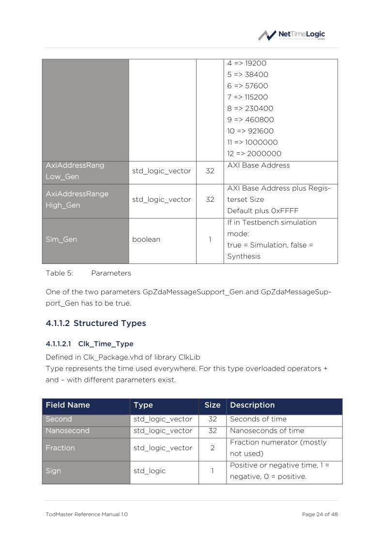
4.4 Clocking and Reset Concept
4.4.1 Clocking
To keep the design as robust and simple as possible, the whole TOD Master Clock,
including the Counter Clock and all other cores from NetTimeLogic are run in one
clock domain. This is considered to be the system clock. Per default this clock is
50MHz. Where possible also the interfaces are run synchronous to this clock. For
clock domain crossing asynchronous fifos with gray counters or message patterns
with meta-stability flip-flops are used. Clock domain crossings for the AXI interface
is moved from the AXI slave to the AXI interconnect.
Clock Frequency Description
System
System Clock 50MHz
(Default)
System clock where the Tod Master runs
on as well as the counter clock etc.
UART Interface
UART TX 9.6 kHz – 1MHz
No clock, asynchronous data signal,
transmit clock of the UART. Must be
defined for the core prior to use of the
interface not all frequencies apply.
Generated out of the System Clock
AXI Interface
AXI Clock 50MHz
(Default)
Internal AXI bus clock, same as the
system clock
Table 13: Clocks
4.4.2 Reset
In connection with the clocks, there is a reset signal for each clock domain. All
resets are active low. All resets can be asynchronously set and shall be synchro-
nously released with the corresponding clock domain. All resets shall be asserted
for the first couple (around 8) clock cycles. All resets shall be set simultaneously
and released simultaneously to avoid overflow conditions in the core. See the
reference designs top file for an example of how the reset shall be handled.

TodMaster Reference Manual 1.0 Page 41 of 48
Reset Polarity Description
System
System Reset Active low Asynchronous set, synchronous release
with the system clock
AXI Interface
AXI Reset Active low
Asynchronous set, synchronous release
with the AXI clock, which is the same as
the system clock
Table 14: Resets

TodMaster Reference Manual 1.0 Page 42 of 48
5 Resource Usage
Since the FPGA Architecture between vendors and FPGA families differ there is a
split up into the two major FPGA vendors.
5.1 Altera (Cyclone V)
Configuration FFs LUTs BRAMs DSPs
Minimal
(Static Config) 442 2003 0 0
Maximal (AXI Config) 487 2142 0 0
Table 15: Resource Usage Altera
5.2 Xilinx (Artix 7)
Configuration FFs LUTs BRAMs DSPs
Minimal
(Static Config) 401 1781 0 0
Maximal (AXI Config) 444 1889 0 0
Table 16: Resource Usage Xilinx

TodMaster Reference Manual 1.0 Page 43 of 48
6 Delivery Structure
AXI -- AXI library folder
|-Library -- AXI library component sources
|-Package -- AXI library package sources
CLK -- CLK library folder
|-Library -- CLK library component sources
|-Package -- CLK library package sources
COMMON -- COMMON library folder
|-Library -- COMMON library component sources
|-Package -- COMMON library package sources
PPS -- PPS library folder
|-Package -- PPS library package sources
SIM -- SIM library folder
|-Doc -- SIM library command documentation
|-Package -- SIM library package sources
|-Tools -- SIM simulation tools
TOD -- TOD library folder
|-Core -- TOD library cores
|-Doc -- TOD library cores documentations
|-Library -- TOD library component sources
|-Package -- TOD library package sources
|-Refdesign -- TOD library cores reference designs
|-Testbench -- TOD library cores testbench sources and sim/log

TodMaster Reference Manual 1.0 Page 44 of 48
7 Testbench
The Tod Master testbench consist of 3 parse/port types: AXI, CLK and TOD.
The TOD receiver port takes the time of the Clock instance as a reference and the
NMEA data stream from the DUT and compares the distributed time with the time
from the Clock. In addition for configuration and result checks an AXI read and
write port is used in the testbench and for accessing more than one AXI slave also
an AXI interconnect is required.
AXI0AXI
READPORT
TODPARSER
AXIPARSER
CLKPARSER
TOD0TODRX
PORT
AXIINTERC.
TODMASTER
(DUT)
AXI0AXI
WRITEPORT
TOD0CLK
PORT
SIM
LOG
GENERALPARSER
CLKCLOCK
Time
Figure 10: Testbench Framework
For more information on the testbench framework check the Sim_ReferenceManual
documentation.
With the Sim parameter set the time base for timeouts are divided by 100 to
100000 to speed up simulation time.
7.1 Run Testbench
1. Run the general script first
source XXX/SIM/Tools/source_with_args.tcl
2. Start the testbench with all test cases
src XXX/TOD/Testbench/Core/TodMaster/Script/run_Tod_Master_Tb.tcl
3. Check the log file LogFile1.txt in the
XXX/TOD/Testbench/Core/TodMaster/Log/ folder for simulation results.

TodMaster Reference Manual 1.0 Page 45 of 48
8 Reference Designs
The TOD Master reference design contains a PLL to generate all necessary clocks
(cores are run at 50 MHz), an instance of the TOD Master Clock IP core and an
instance of the Adjustable Counter Clock IP core (needs to be purchased separate-
ly). Optionally it also contains an instance of a PPS Master Clock IP core (has to be
purchased separately). To instantiate the optional IP core, change the correspond-
ing generic (PpsMasterAvailable_Gen,) to true via the tool specific wizards.
The Reference Design with a PPS and TOD Master Clock is intended to be con-
nected to a NMEA sink with a baudrate of 9600. If another baud rate shall be used
this can be set via the Static Configuration. The absolute second is distributed via
the TOD Master. The PPS Master Clock is used to create a PPS output which is
compensated for the output delay and has a configurable duty cycle, if not availa-
ble an uncompensated PPS is directly generated out of the MSB of the Time.
All generics can be adapted to the specific needs.
TODMaster
CLOCKAdjustable Clock
NMEA
PPS
AXI4 Lite Slave
TodRefDesignTodRefDesign
PPSMaster
AXI4 Lite Slave
AXI4 Lite Slave
Time & Timer
PLL
Figure 11: Reference Design
8.1 Altera: Terasic SocKit
The SocKit board is an FPGA board from Terasic Inc. with a Cyclone V SoC FPGA
from Altera. (http://www.terasic.com.tw/cgi-
bin/page/archive.pl?Language=English&CategoryNo=205&No=816)
1. Open Quartus 15.x
2. Open Project /TOD/Refdesign/Altera/SocKit/TodMaster/TodMaster.qpf
3. If the optional core PPS Master Clock is available add the files from the cor-
responding folders (PPS/Core, PPS/Library, PPS/Package and CLK/Library)
4. Change the generic (PpsMasterAvailable_Gen) in Quartus (in the settings
menu, not in VHDL) to true for the optional cores that are available.
TodMaster Reference Manual 1.0 Page 46 of 48
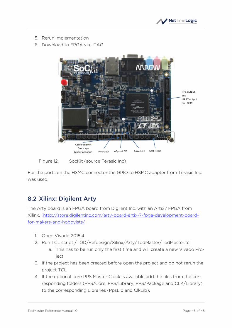
5. Rerun implementation
6. Download to FPGA via JTAG
Figure 12: SocKit (source Terasic Inc)
For the ports on the HSMC connector the GPIO to HSMC adapter from Terasic Inc.
was used.
8.2 Xilinx: Digilent Arty
The Arty board is an FPGA board from Digilent Inc. with an Artix7 FPGA from
Xilinx. (http://store.digilentinc.com/arty-board-artix-7-fpga-development-board-
for-makers-and-hobbyists/
1. Open Vivado 2015.4
2. Run TCL script /TOD/Refdesign/Xilinx/Arty/TodMaster/TodMaster.tcl
a. This has to be run only the first time and will create a new Vivado Pro-
ject
3. If the project has been created before open the project and do not rerun the
project TCL
4. If the optional core PPS Master Clock is available add the files from the cor-
responding folders (PPS/Core, PPS/Library, PPS/Package and CLK/Library)
to the corresponding Libraries (PpsLib and ClkLib).
PPS-LED InSync-LED Alive-LED Soft Reset
PPS output,
and
UART output
on HSMC
Cable delay in
5ns steps
binary encoded

TodMaster Reference Manual 1.0 Page 47 of 48
5. Change the generic (PpsMasterAvailable_Gen) in Vivado (in the settings
menu, not in VHDL) to true for the optional cores that are available.
6. Rerun implementation
7. Download to FPGA via JTAG
Figure 13: Arty (source Digilent Inc)
PPS-LED InSync-LED Alive-LED Soft Reset
PPS output
UART output
Cable delay in
5ns steps
binary encoded

TodMaster Reference Manual 1.0 Page 48 of 48
A List of tables
Table 1: Revision History ......................................................................................................................4
Table 2: Definitions .................................................................................................................................. 7
Table 3: Abbreviations .......................................................................................................................... 8
Table 4: Register Set Overview ...................................................................................................... 15
Table 5: Parameters ............................................................................................................................. 24
Table 6: Clk_Time_Type .................................................................................................................... 25
Table 7: Tod_MasterStaticConfig_Type .................................................................................... 25
Table 8: Tod_MasterStaticConfigVal_Type ............................................................................. 26
Table 9: TOD Master Clock .............................................................................................................. 29
Table 10: TX Processor ......................................................................................................................... 32
Table 11: UART Interface Adapter ................................................................................................. 34
Table 12: Registerset ............................................................................................................................. 38
Table 13: Clocks ...................................................................................................................................... 40
Table 14: Resets ........................................................................................................................................ 41
Table 15: Resource Usage Altera .................................................................................................... 42
Table 16: Resource Usage Xilinx ...................................................................................................... 42
B List of figures
Figure 1: Context Block Diagram ...................................................................................................... 9
Figure 2: Architecture Block Diagram ........................................................................................... 10
Figure 3: NMEA to PPS alignment .................................................................................................. 13
Figure 4: TOD Master Clock .............................................................................................................. 26
Figure 5: TX Processor ......................................................................................................................... 30
Figure 6: UART Interface Adapter ................................................................................................. 33
Figure 7: Registerset ............................................................................................................................. 35
Figure 8: Static Configuration .......................................................................................................... 39
Figure 9: AXI Configuration ............................................................................................................... 39
Figure 10: Testbench Framework ................................................................................................ 44
Figure 11: Reference Design ................................................................................................................ 45
Figure 12: SocKit (source Terasic Inc) ....................................................................................... 46
Figure 13: Arty (source Digilent Inc) .......................................................................................... 47


![[XLS] National Bank.xls · Web viewRAJIV KUMAR 0183-2570024 bo4164@pnb.co.in HALL BAZAR, AMRITSAR J.P. SINGH 0183-5010652 0183-2543825 bo0018@pnb.co.in PUNJAB NATIONAL BANK HANSLI](https://img.pdfslide.us/doc/110x75/5aa125267f8b9a46238b5bc1/xls-national-bankxlsweb-viewrajiv-kumar-0183-2570024-bo4164pnbcoin-hall-bazar.jpg)