Embed Size (px)
Citation preview
Page 1 of 19
TODAY’S COUPON: 425 MGD PUMP STATION AT 30% OFF
Erin Flanagan, P.E. Freese and Nichols, Inc.
1701 North Market Street Suite 500, LB 51
Dallas, Texas 75202
Bryan Jann, P.E. Freese and Nichols, Inc.
Regina Stencel, P.E. Dallas Water Utilities
ABSTRACT The City of Dallas Water Utilities (DWU) has purchased the 425 MGD pump station deal for just over $49 million dollars, at a 30% savings. About this deal:
- One location – Central Wastewater Treatment Plant, Dallas, Texas - The world’s largest capacity trench type wet well - The world’s largest capacity-based and deepest set Vertical Turbine Solids Handling
Pumps (VTSH) installation - An Influent Pump Station (IPS) capable of sending flows to multiple locations
The planned decommissioning of DWU’s aging Cadiz Street Pump Station (Cadiz P.S.) has spurred the design and construction of a new IPS at the Central Wastewater Treatment Plant (CWWTP) to assist in peak flow management, provide long term influent pumping to supplement the existing White Rock Raw Sewage Pump Station (WRRSPS), and provide a higher hydraulic head for future treatment units. Pumping equipment selection guided the IPS layout and hydraulic design components. Traditional centrifugal pumps with dry well arrangements were evaluated with the space-saving VTSH trench type design. In addition to a smaller overall footprint, the trench type wet well offers a lower maintenance design with all required maintenance accessible at ground level, the ability to meet minimum flows of 20 MGD at greater efficiencies over centrifugal pumps, ease of expansion to meet future influent flows, and construction cost savings of 30% over traditional centrifugal dry well designs. All IPS flows will first pass through an upstream coarse screening facility that will utilize a four (4) channel design. Three (3) coarse screens will be initially installed with the fourth channel reserved for a future screen. Each screen will reach to a depth of 47 feet with a peak flow screening capacity of 161 MGD through 1-inch bar openings. Screenings captured and removed by the conventional chain-type screens will be transported by water sluice to a screenings processing room for washing and compacting. The IPS, currently under construction, will include an initial firm pumping capacity of 335 MGD to be divided among six (6) pumps with slots for two (2) future pumps. At build out, the pump station will have a pumping capacity of 425 MGD with a maximum hydraulic capacity of 465
Page 2 of 19
MGD. An associated new junction structure, biofilter complex, electrical building, valve vault, and meter vault will be constructed to support the IPS. The IPS construction began in September 2011 with a 27 month construction contract. In addition to providing information related to the IPS equipment selection and project components, design challenges included navigating the coordination associated with the pump station’s close proximity to the Trinity River levee, influent hydraulic coordination between the IPS and WRRSPS, and final facility siting will be included in the paper. KEYWORDS Peak flow management, pump station, hydraulic modeling, trench type INTRODUCTION The planned decommissioning of an aging pump station for the City of Dallas Water Utilities’ (DWU) has spurred the design and construction of the world’s largest capacity-based and deepest set vertical turbine solids handling (VTSH) pump installation: the new Influent Pump Station (IPS) at the DWU Central Wastewater Treatment Plant (CWWTP). The ultimate purpose of the new IPS is:
to provide a long-term influent pumping solution to supplement two existing peak flow pump stations and work in conjunction with another existing influent pump station;
to assist in peak wet weather flow management and diversion to peak flow storage; to provide a higher level of flow control and accuracy in flow splitting to two separate
treatment trains at different hydraulic grade lines, and; to provide a higher hydraulic grade line for future treatment units, including future
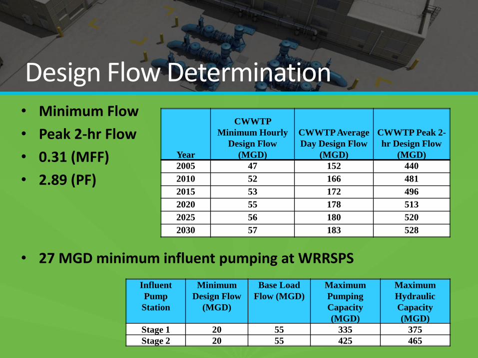
headworks facilities and primaries. At the heart of the IPS will be a trench type wet well with non-traditional VTSH pumps. An initial firm pumping capacity of 335 MGD will be divided among six (6) pumps with slots for two (2) future pumps. Each pump will have a 42 inch diameter column with a 62 foot overall length. At build out, the pump station will have a normal pumping capacity of 425 MGD with a maximum hydraulic capacity of 465 MGD. With the use of flow control valves, the IPS can discharge to two locations simultaneously under differing head conditions. An associated new coarse screening facility, influent junction structure, biofilter complex, electrical building, valve vault, and meter vault will be constructed to support the IPS. PRELIMINARY DESIGN APPROACH Preliminary design for the new IPS began in 2005 with the determination of the flows for the basis of design. Minimum hourly design flows were estimated based on historical data analysis of the Cadiz P.S. pumping rates, anticipated interceptor minimum flow rates, and the minimum pumping capacity of the WRRSPS. A 0.31 minimum flow factor was calculated for 2005 and was applied to the average day design flows to calculate the projected minimum flows to the year 2030. The peak 2-hour design flows were developed based on available interceptor capacity and plant data related to a peak flow occurrence event. A peaking factor of 2.89 was developed and incorporated into the flow projections provided in Table 1.
Page 3 of 19
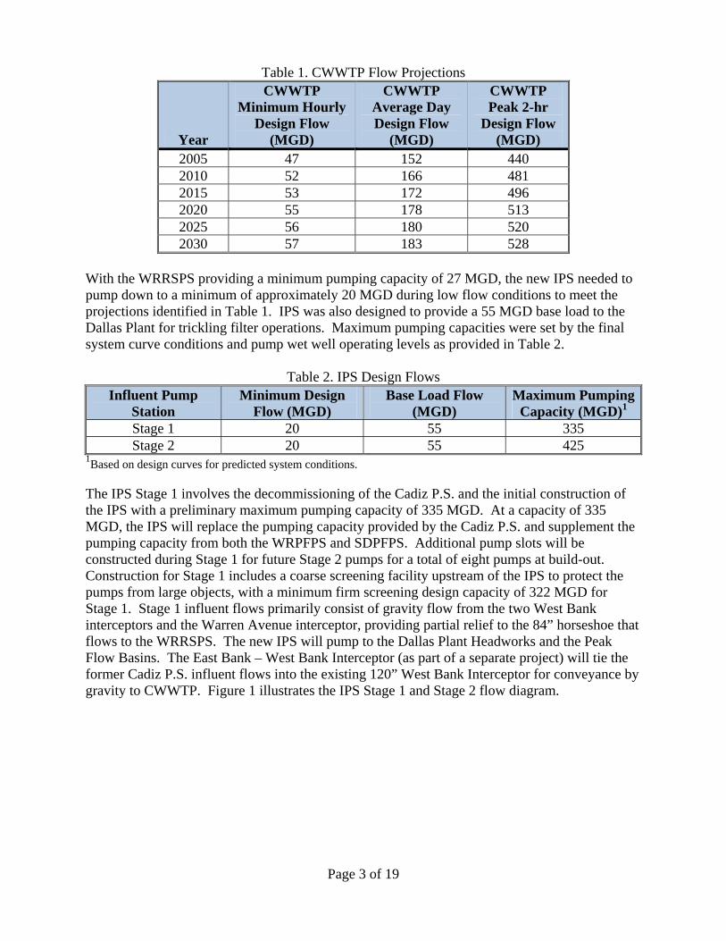
Table 1. CWWTP Flow Projections
Year
CWWTP Minimum Hourly
Design Flow (MGD)
CWWTP Average Day Design Flow
(MGD)
CWWTP Peak 2-hr
Design Flow (MGD)
2005 47 152 440 2010 52 166 481 2015 53 172 496 2020 55 178 513 2025 56 180 520 2030 57 183 528
With the WRRSPS providing a minimum pumping capacity of 27 MGD, the new IPS needed to pump down to a minimum of approximately 20 MGD during low flow conditions to meet the projections identified in Table 1. IPS was also designed to provide a 55 MGD base load to the Dallas Plant for trickling filter operations. Maximum pumping capacities were set by the final system curve conditions and pump wet well operating levels as provided in Table 2.
Table 2. IPS Design Flows Influent Pump
Station Minimum Design
Flow (MGD) Base Load Flow
(MGD) Maximum Pumping
Capacity (MGD)1 Stage 1 20 55 335 Stage 2 20 55 425
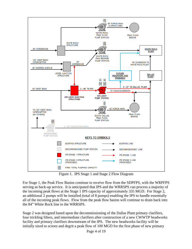
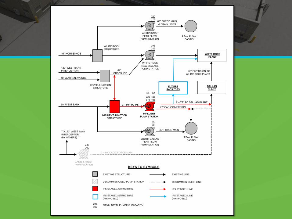
1Based on design curves for predicted system conditions. The IPS Stage 1 involves the decommissioning of the Cadiz P.S. and the initial construction of the IPS with a preliminary maximum pumping capacity of 335 MGD. At a capacity of 335 MGD, the IPS will replace the pumping capacity provided by the Cadiz P.S. and supplement the pumping capacity from both the WRPFPS and SDPFPS. Additional pump slots will be constructed during Stage 1 for future Stage 2 pumps for a total of eight pumps at build-out. Construction for Stage 1 includes a coarse screening facility upstream of the IPS to protect the pumps from large objects, with a minimum firm screening design capacity of 322 MGD for Stage 1. Stage 1 influent flows primarily consist of gravity flow from the two West Bank interceptors and the Warren Avenue interceptor, providing partial relief to the 84” horseshoe that flows to the WRRSPS. The new IPS will pump to the Dallas Plant Headworks and the Peak Flow Basins. The East Bank – West Bank Interceptor (as part of a separate project) will tie the former Cadiz P.S. influent flows into the existing 120” West Bank Interceptor for conveyance by gravity to CWWTP. Figure 1 illustrates the IPS Stage 1 and Stage 2 flow diagram.
Page 4 of 19
Figure 1. IPS Stage 1 and Stage 2 Flow Diagram
For Stage 1, the Peak Flow Basins continue to receive flow from the SDPFPS, with the WRPFPS serving as back-up service. It is anticipated that IPS and the WRRSPS can process a majority of the incoming peak flows at the Stage 1 IPS capacity of approximately 335 MGD. For Stage 2, an additional 2 pumps will be installed (total of 8 pumps) enabling the IPS to handle essentially all of the incoming peak flows. Flow from the peak flow basins will continue to drain back into the 84” White Rock line to the WRRSPS. Stage 2 was designed based upon the decommissioning of the Dallas Plant primary clarifiers, four trickling filters, and intermediate clarifiers after construction of a new CWWTP headworks facility and primary clarifiers downstream of the IPS. The new headworks facility will be initially sized to screen and degrit a peak flow of 100 MGD for the first phase of new primary
Page 5 of 19
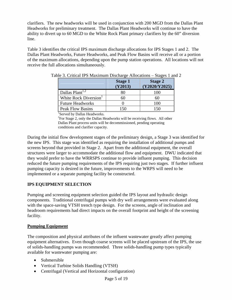
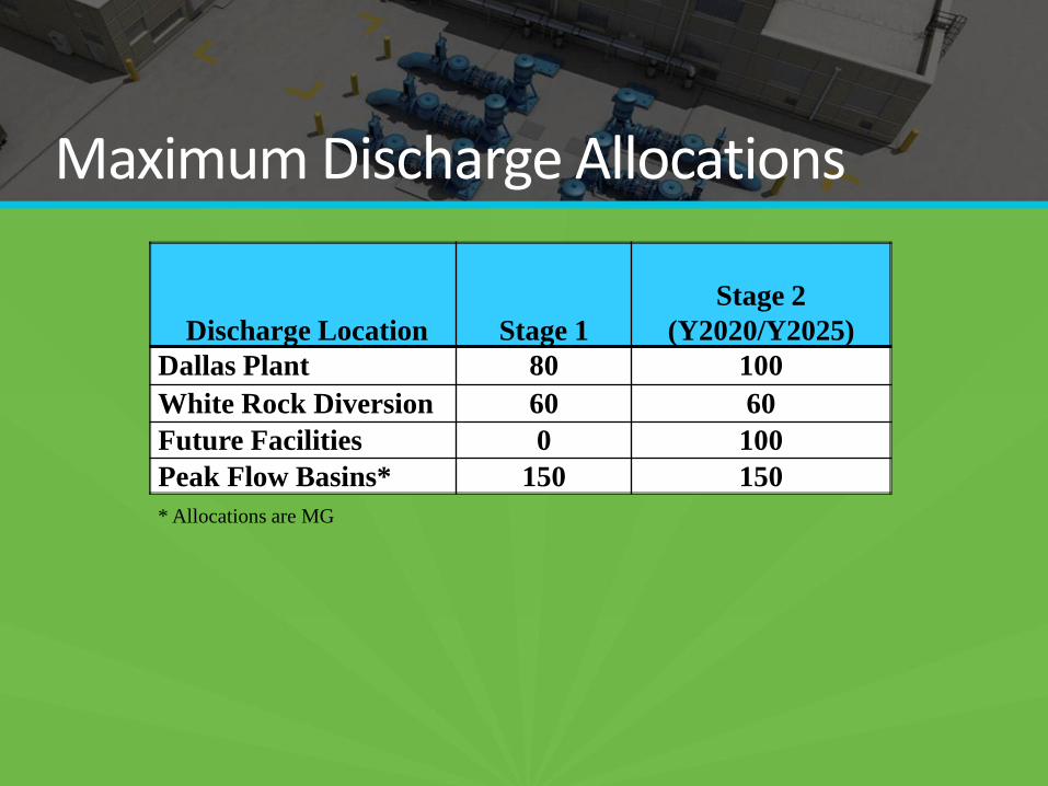
clarifiers. The new headworks will be used in conjunction with 200 MGD from the Dallas Plant Headworks for preliminary treatment. The Dallas Plant Headworks will continue to have the ability to divert up to 60 MGD to the White Rock Plant primary clarifiers by the 60” diversion line. Table 3 identifies the critical IPS maximum discharge allocations for IPS Stages 1 and 2. The Dallas Plant Headworks, Future Headworks, and Peak Flow Basins will receive all or a portion of the maximum allocations, depending upon the pump station operations. All locations will not receive the full allocations simultaneously.
Table 3. Critical IPS Maximum Discharge Allocations – Stages 1 and 2
Stage 1 (Y2013)
Stage 2 (Y2020/Y2025)
Dallas Plant1,2 80 100 White Rock Diversion1 60 60 Future Headworks 0 100 Peak Flow Basins 150 150
1Served by Dallas Headworks. 2For Stage 2, only the Dallas Headworks will be receiving flows. All other Dallas Plant process units will be decommissioned, pending operating conditions and clarifier capacity.
During the initial flow development stages of the preliminary design, a Stage 3 was identified for the new IPS. This stage was identified as requiring the installation of additional pumps and screens beyond that provided in Stage 2. Apart from the additional equipment, the overall structures were larger to accommodate the additional flow and equipment. DWU indicated that they would prefer to have the WRRSPS continue to provide influent pumping. This decision reduced the future pumping requirements of the IPS requiring just two stages. If further influent pumping capacity is desired in the future, improvements to the WRPS will need to be implemented or a separate pumping facility be constructed. IPS EQUIPMENT SELECTION Pumping and screening equipment selection guided the IPS layout and hydraulic design components. Traditional centrifugal pumps with dry well arrangements were evaluated along with the space-saving VTSH trench type design. For the screens, angle of inclination and headroom requirements had direct impacts on the overall footprint and height of the screening facility. Pumping Equipment The composition and physical attributes of the influent wastewater greatly affect pumping equipment alternatives. Even though coarse screens will be placed upstream of the IPS, the use of solids-handling pumps was recommended. Three solids-handling pump types typically available for wastewater pumping are:
Submersible Vertical Turbine Solids Handling (VTSH) Centrifugal (Vertical and Horizontal configuration)
Page 6 of 19
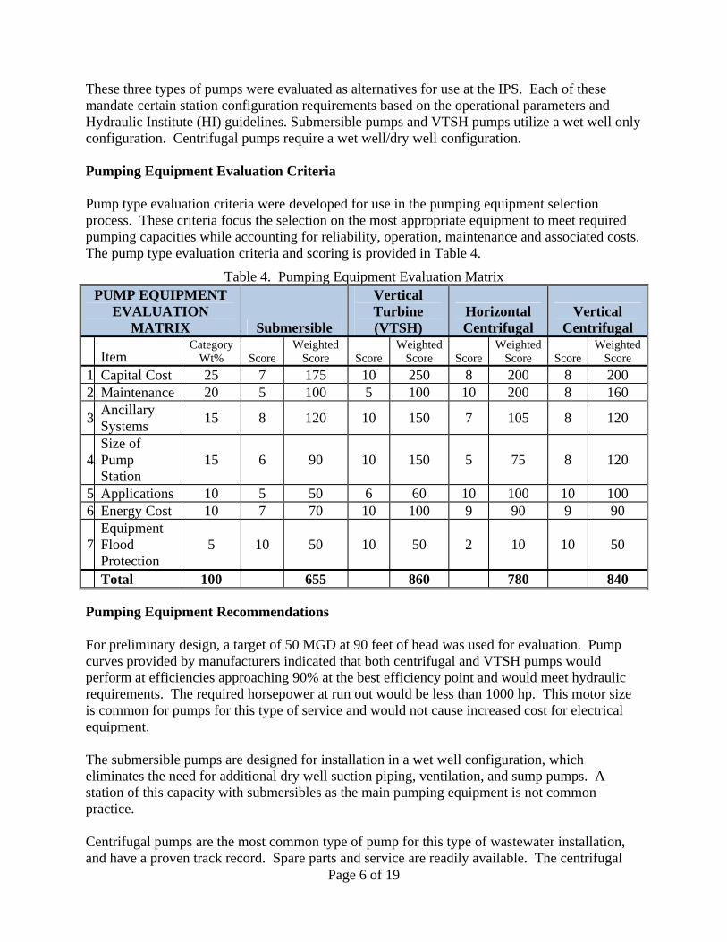
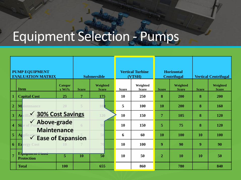
These three types of pumps were evaluated as alternatives for use at the IPS. Each of these mandate certain station configuration requirements based on the operational parameters and Hydraulic Institute (HI) guidelines. Submersible pumps and VTSH pumps utilize a wet well only configuration. Centrifugal pumps require a wet well/dry well configuration. Pumping Equipment Evaluation Criteria Pump type evaluation criteria were developed for use in the pumping equipment selection process. These criteria focus the selection on the most appropriate equipment to meet required pumping capacities while accounting for reliability, operation, maintenance and associated costs. The pump type evaluation criteria and scoring is provided in Table 4.
Table 4. Pumping Equipment Evaluation Matrix
Pumping Equipment Recommendations For preliminary design, a target of 50 MGD at 90 feet of head was used for evaluation. Pump curves provided by manufacturers indicated that both centrifugal and VTSH pumps would perform at efficiencies approaching 90% at the best efficiency point and would meet hydraulic requirements. The required horsepower at run out would be less than 1000 hp. This motor size is common for pumps for this type of service and would not cause increased cost for electrical equipment. The submersible pumps are designed for installation in a wet well configuration, which eliminates the need for additional dry well suction piping, ventilation, and sump pumps. A station of this capacity with submersibles as the main pumping equipment is not common practice. Centrifugal pumps are the most common type of pump for this type of wastewater installation, and have a proven track record. Spare parts and service are readily available. The centrifugal
PUMP EQUIPMENT EVALUATION
MATRIX Submersible
Vertical Turbine (VTSH)
Horizontal Centrifugal
Vertical Centrifugal
Item Category
Wt% Score Weighted
Score Score Weighted
Score Score Weighted
Score Score Weighted
Score
1 Capital Cost 25 7 175 10 250 8 200 8 200 2 Maintenance 20 5 100 5 100 10 200 8 160
3 Ancillary Systems
15 8 120 10 150 7 105 8 120
4 Size of Pump Station
15 6 90 10 150 5 75 8 120
5 Applications 10 5 50 6 60 10 100 10 100 6 Energy Cost 10 7 70 10 100 9 90 9 90
7 Equipment Flood Protection
5 10 50 10 50 2 10 10 50
Total 100 655 860 780 840
Page 7 of 19
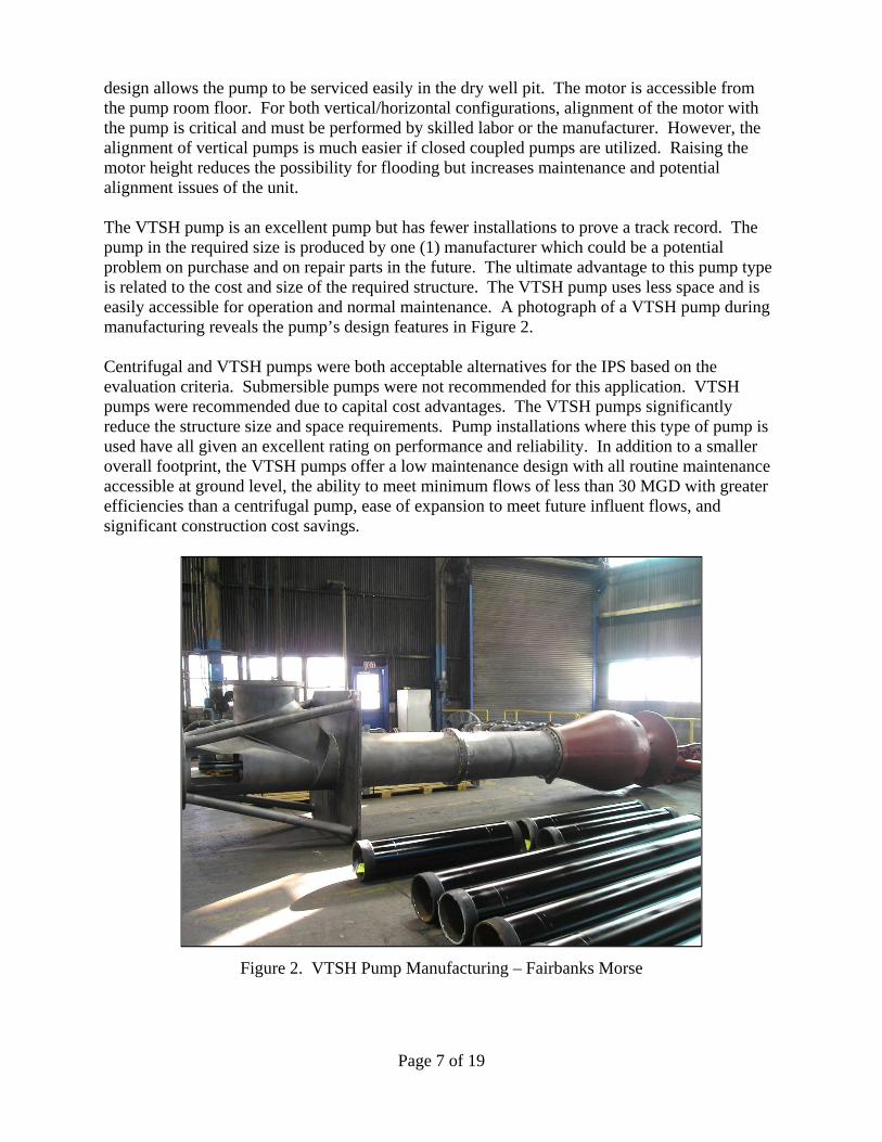
design allows the pump to be serviced easily in the dry well pit. The motor is accessible from the pump room floor. For both vertical/horizontal configurations, alignment of the motor with the pump is critical and must be performed by skilled labor or the manufacturer. However, the alignment of vertical pumps is much easier if closed coupled pumps are utilized. Raising the motor height reduces the possibility for flooding but increases maintenance and potential alignment issues of the unit. The VTSH pump is an excellent pump but has fewer installations to prove a track record. The pump in the required size is produced by one (1) manufacturer which could be a potential problem on purchase and on repair parts in the future. The ultimate advantage to this pump type is related to the cost and size of the required structure. The VTSH pump uses less space and is easily accessible for operation and normal maintenance. A photograph of a VTSH pump during manufacturing reveals the pump’s design features in Figure 2. Centrifugal and VTSH pumps were both acceptable alternatives for the IPS based on the evaluation criteria. Submersible pumps were not recommended for this application. VTSH pumps were recommended due to capital cost advantages. The VTSH pumps significantly reduce the structure size and space requirements. Pump installations where this type of pump is used have all given an excellent rating on performance and reliability. In addition to a smaller overall footprint, the VTSH pumps offer a low maintenance design with all routine maintenance accessible at ground level, the ability to meet minimum flows of less than 30 MGD with greater efficiencies than a centrifugal pump, ease of expansion to meet future influent flows, and significant construction cost savings.
Figure 2. VTSH Pump Manufacturing – Fairbanks Morse
Page 8 of 19
Pump Control Variable Frequency Drives (VFDs) are proposed for all six (6) Stage 1 pumps and are planned for the two (2) Stage 2 pumps. This control strategy will allow the system to match inflow with pumped flow for most anticipated flow conditions and will also allow operational flexibility and consistent pump run times among all pumps. A single modulating plug valve is proposed to control the distribution of discharge flows between the headworks and the peak flow basins. Each individual pump discharge consists of an isolation knife gate valve and swing check valve. Based on the installation of VFDs and the discharge piping configuration, electronic or hydraulic pump control valves were not recommended or installed. Screening Equipment Six coarse screening equipment types were evaluated for operation at the IPS screening facility.
Conventional Chain Catenary Chain Cog Wheel/Climber Hydraulic Telescoping Gripper Rope/Cable
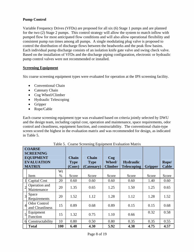
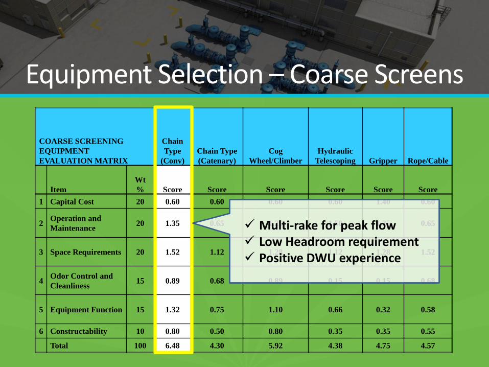
Each coarse screening equipment type was evaluated based on criteria jointly selected by DWU and the design team, including capital cost, operation and maintenance, space requirements, odor control and cleanliness, equipment function, and constructability. The conventional chain-type screen scored the highest in the evaluation matrix and was recommended for design, as indicated in Table 5.
Table 5. Coarse Screening Equipment Evaluation Matrix COARSE SCREENING EQUIPMENT EVALUATION MATRIX
Chain Type
(Conv)
Chain Type
(Catenary)
Cog Wheel/
ClimberHydraulic
Telescoping GripperRope/Cable
Item Wt % Score Score Score Score Score Score
1 Capital Cost 20 0.60 0.60 0.60 0.60 1.40 0.60
2 Operation and Maintenance
20 1.35 0.65 1.25 1.50 1.25 0.65
3 Space Requirements
20 1.52 1.12 1.28 1.12 1.28 1.52
4 Odor Control and Cleanliness
15 0.89 0.68 0.89 0.15 0.15 0.68
5 Equipment Function
15 1.32 0.75 1.10 0.66 0.32 0.58
6 Constructability 10 0.80 0.50 0.80 0.35 0.35 0.55 Total 100 6.48 4.30 5.92 4.38 4.75 4.57
Page 9 of 19
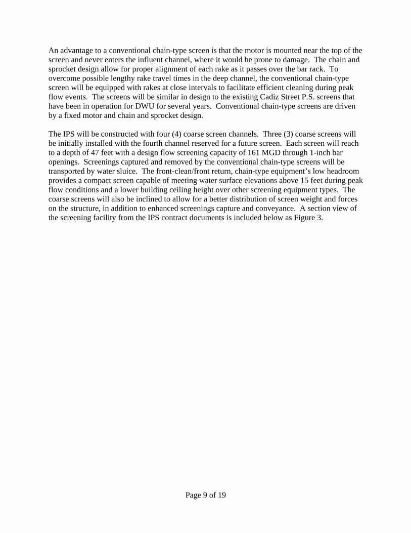
An advantage to a conventional chain-type screen is that the motor is mounted near the top of the screen and never enters the influent channel, where it would be prone to damage. The chain and sprocket design allow for proper alignment of each rake as it passes over the bar rack. To overcome possible lengthy rake travel times in the deep channel, the conventional chain-type screen will be equipped with rakes at close intervals to facilitate efficient cleaning during peak flow events. The screens will be similar in design to the existing Cadiz Street P.S. screens that have been in operation for DWU for several years. Conventional chain-type screens are driven by a fixed motor and chain and sprocket design. The IPS will be constructed with four (4) coarse screen channels. Three (3) coarse screens will be initially installed with the fourth channel reserved for a future screen. Each screen will reach to a depth of 47 feet with a design flow screening capacity of 161 MGD through 1-inch bar openings. Screenings captured and removed by the conventional chain-type screens will be transported by water sluice. The front-clean/front return, chain-type equipment’s low headroom provides a compact screen capable of meeting water surface elevations above 15 feet during peak flow conditions and a lower building ceiling height over other screening equipment types. The coarse screens will also be inclined to allow for a better distribution of screen weight and forces on the structure, in addition to enhanced screenings capture and conveyance. A section view of the screening facility from the IPS contract documents is included below as Figure 3.
Page 10 of 19
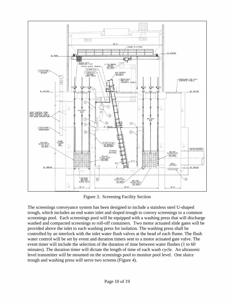
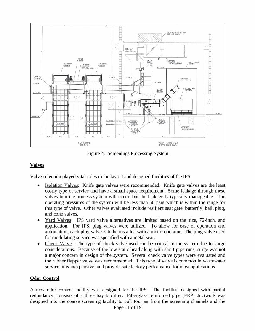
Figure 3. Screening Facility Section The screenings conveyance system has been designed to include a stainless steel U-shaped trough, which includes an end water inlet and sloped trough to convey screenings to a common screenings pool. Each screenings pool will be equipped with a washing press that will discharge washed and compacted screenings to roll-off containers. Two motor actuated slide gates will be provided above the inlet to each washing press for isolation. The washing press shall be controlled by an interlock with the inlet water flush valves at the head of each flume. The flush water control will be set by event and duration timers sent to a motor actuated gate valve. The event timer will include the selection of the duration of time between water flushes (1 to 60 minutes). The duration timer will dictate the length of time of each wash cycle. An ultrasonic level transmitter will be mounted on the screenings pool to monitor pool level. One sluice trough and washing press will serve two screens (Figure 4).
Page 11 of 19
Figure 4. Screenings Processing System Valves Valve selection played vital roles in the layout and designed facilities of the IPS.
Isolation Valves: Knife gate valves were recommended. Knife gate valves are the least costly type of service and have a small space requirement. Some leakage through these valves into the process system will occur, but the leakage is typically manageable. The operating pressures of the system will be less than 50 psig which is within the range for this type of valve. Other valves evaluated include resilient seat gate, butterfly, ball, plug, and cone valves.
Yard Valves: IPS yard valve alternatives are limited based on the size, 72-inch, and application. For IPS, plug valves were utilized. To allow for ease of operation and automation, each plug valve is to be installed with a motor operator. The plug valve used for modulating service was specified with a metal seat.
Check Valve: The type of check valve used can be critical to the system due to surge considerations. Because of the low static head along with short pipe runs, surge was not a major concern in design of the system. Several check valve types were evaluated and the rubber flapper valve was recommended. This type of valve is common in wastewater service, it is inexpensive, and provide satisfactory performance for most applications.
Odor Control A new odor control facility was designed for the IPS. The facility, designed with partial redundancy, consists of a three bay biofilter. Fiberglass reinforced pipe (FRP) ductwork was designed into the coarse screening facility to pull foul air from the screening channels and the
Page 12 of 19
mezzanine level. In addition, foul air piping was extended to the new junction structure as well as the pump station wet well. Screenings are to be washed as part of the processing and the associated roll-off container areas were not odor-controlled. Fresh air supply to the coarse screening facility is provided by rooftop air handling units. Air is forced down into the mezzanine level and foul air is pulled out via the ductwork and three foul air blowers located adjacent to the biofilter complex. PUMP STATION AND FACILITY LAYOUTS Four basic facility concepts were considered, based on pump type and wet well location. The four configurations are as follows:
(1) Centrifugal Pumps with Perimeter Wet Wells
(2) Centrifugal Pumps with Center Wet Wells
(3) Vertical Turbine Pumps with Perimeter Wet Wells
(4) Vertical Turbine Pumps with Center Wet Wells
From these four suction concepts, variations in pump station layout were developed, producing a total of 15 layout concepts for consideration.
Concepts with the pumps located along the center of the station offer the advantage of consolidating the equipment which needs the most maintenance, reducing walking distance and time. Furthermore, the electrical cables and miscellaneous mechanical piping can be consolidated, minimizing costs of longer runs. Pumps located along the perimeter can also be accessible as well, and this concept was not ruled out.
Wet wells can be located either at the perimeter of the station, sharing a wall with the building, or inside the station along its center. Perimeter wet wells allows all pumps to be installed in a common room which is advantageous for maintenance. The risk of equipment damage due to flooding is increased for the same reason. Two separate structures are required if turbine pumps are selected using perimeter wet wells. Perimeter wet wells for turbine pumps do have the advantage of placing the pumps in locations where they are unobstructed from the back side allowing the pumps to be very accessible. The use of perimeter wet wells for turbine pumps combined with below grade discharge headers would require the wet wells to be constructed a significant distance apart to allow for required layback for header repairs. This layout has no real advantage and was therefore discounted.
Wet wells located at the center of the building provide two pump rooms with a common wet well. For centrifugal pumps, the footprint is further reduced by installing the discharge header outside of the structure. For turbine pumps, this requires the smallest footprint of any option. Access for maintenance is also desirable. The electrical room would be required to be adjacent to the pump station. It is further recommended that a mobile crane be used to service these pumps and motors.
The 15 layout concepts were therefore reduced to six (6) alternative concepts, based on pump type and wet well location, and were considered for the pump station configuration:
Alternative 1 – Centrifugal Pumps and Perimeter Wet Wells with Perimeter Discharge Alternative 2 –Centrifugal Pumps and Center Wet Wells with Center Discharge Alternative 3 – Vertical Turbine Solids Handling Pumps with Perimeter Wet Wells with
Center Discharge

Page 13 of 19
Alternative 4 – Vertical Turbine Solids Handling Pumps Center Wet Wells with Perimeter Discharge
Alternative 5 – Vertical Turbine Solids Handling Pumps Center Wet Wells with Perimeter Discharge, (Reduced size from Alternative 4)
Alternative 6 –Centrifugal Pumps and Center Wet Wells with Center Discharge, (Reduced Size from Alternative 2)
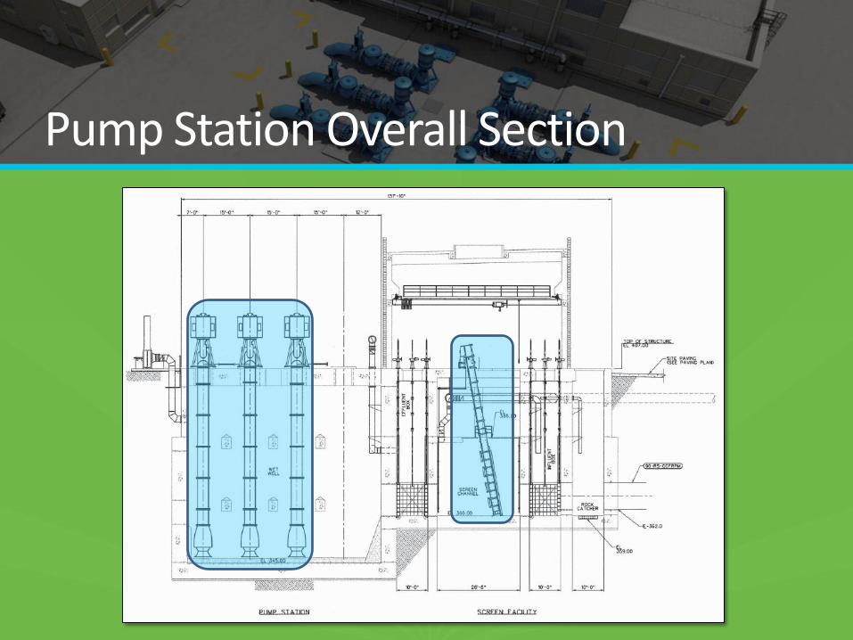
Alternative 5 was the recommended pump station layout. It provided the required functionality in terms of station operation and staff maintenance in the most efficient space and most economical manner. The construction cost for this station is the lowest of the six alternatives. A section view of the IPS is provided as Figure 5.
Figure 5. Overall Section of Pump Station Facility Site Layout The evaluation of possible sites for the CWWTP IPS was based on several factors including constructability, structural requirements, tie-in configuration, adequate space for construction, access, compatibility with treatment facilities, flexibility with current and future plant/process flow schematics, influent and discharge piping, and capital costs.
Several alternative sites were considered inclusive of sites recommended by a previous influent pump station feasibility report and are identified in Figure 6 below.
Page 14 of 19
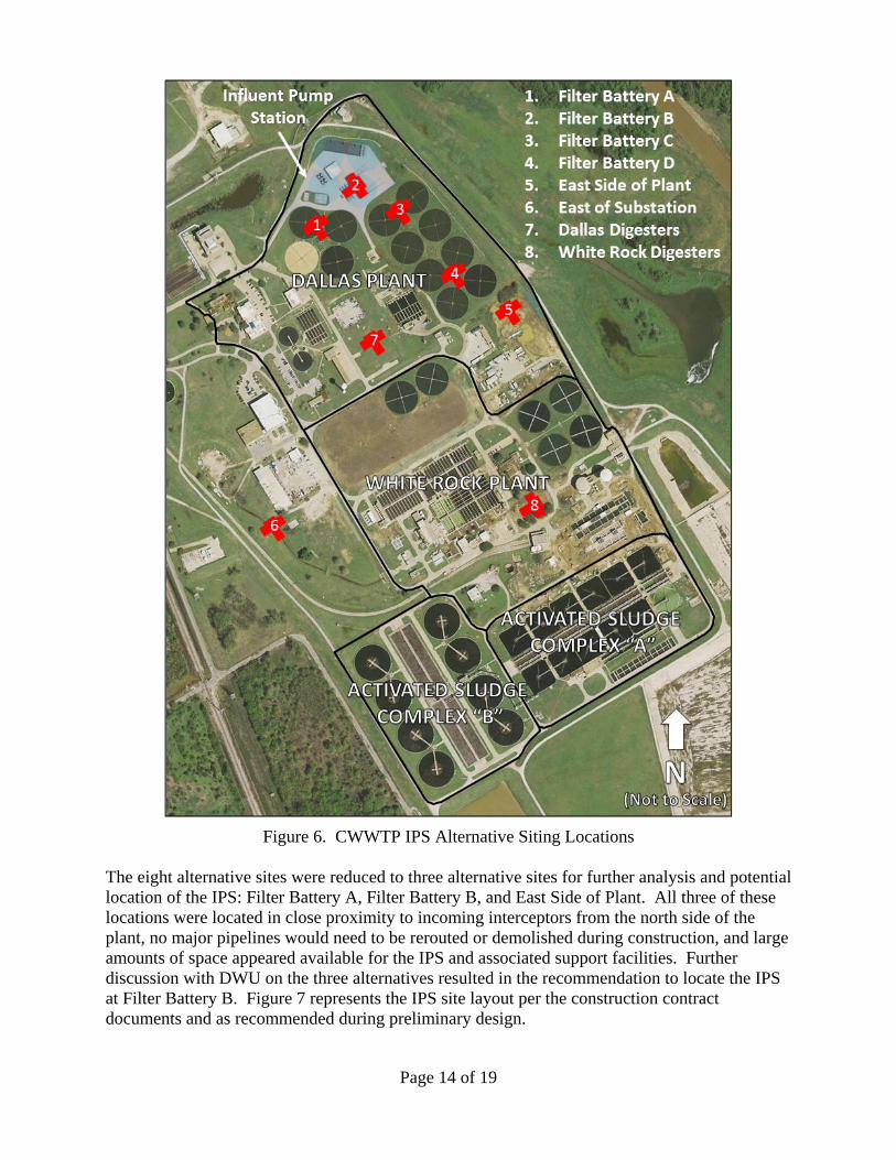
Figure 6. CWWTP IPS Alternative Siting Locations
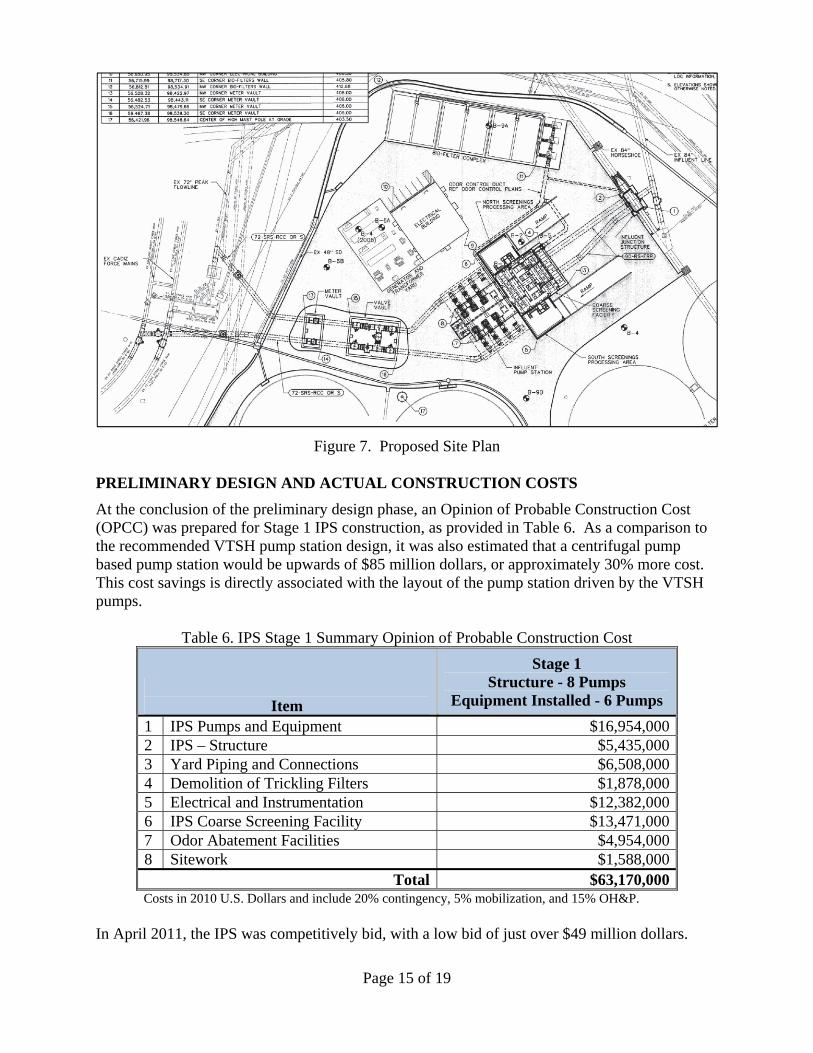
The eight alternative sites were reduced to three alternative sites for further analysis and potential location of the IPS: Filter Battery A, Filter Battery B, and East Side of Plant. All three of these locations were located in close proximity to incoming interceptors from the north side of the plant, no major pipelines would need to be rerouted or demolished during construction, and large amounts of space appeared available for the IPS and associated support facilities. Further discussion with DWU on the three alternatives resulted in the recommendation to locate the IPS at Filter Battery B. Figure 7 represents the IPS site layout per the construction contract documents and as recommended during preliminary design.
Page 15 of 19
Figure 7. Proposed Site Plan
PRELIMINARY DESIGN AND ACTUAL CONSTRUCTION COSTS
At the conclusion of the preliminary design phase, an Opinion of Probable Construction Cost (OPCC) was prepared for Stage 1 IPS construction, as provided in Table 6. As a comparison to the recommended VTSH pump station design, it was also estimated that a centrifugal pump based pump station would be upwards of $85 million dollars, or approximately 30% more cost. This cost savings is directly associated with the layout of the pump station driven by the VTSH pumps.
Table 6. IPS Stage 1 Summary Opinion of Probable Construction Cost
Item
Stage 1 Structure - 8 Pumps
Equipment Installed - 6 Pumps
1 IPS Pumps and Equipment $16,954,000 2 IPS – Structure $5,435,000 3 Yard Piping and Connections $6,508,000 4 Demolition of Trickling Filters $1,878,000 5 Electrical and Instrumentation $12,382,000 6 IPS Coarse Screening Facility $13,471,000 7 Odor Abatement Facilities $4,954,000 8 Sitework $1,588,000
Total $63,170,000Costs in 2010 U.S. Dollars and include 20% contingency, 5% mobilization, and 15% OH&P.
In April 2011, the IPS was competitively bid, with a low bid of just over $49 million dollars.
Page 16 of 19
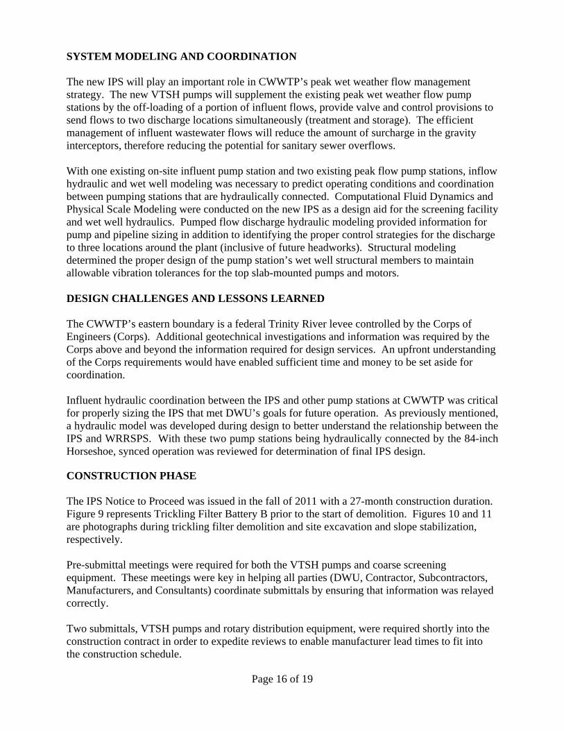
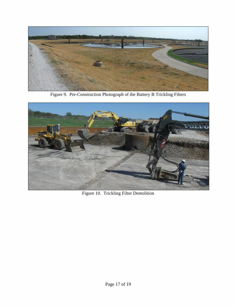
SYSTEM MODELING AND COORDINATION The new IPS will play an important role in CWWTP’s peak wet weather flow management strategy. The new VTSH pumps will supplement the existing peak wet weather flow pump stations by the off-loading of a portion of influent flows, provide valve and control provisions to send flows to two discharge locations simultaneously (treatment and storage). The efficient management of influent wastewater flows will reduce the amount of surcharge in the gravity interceptors, therefore reducing the potential for sanitary sewer overflows. With one existing on-site influent pump station and two existing peak flow pump stations, inflow hydraulic and wet well modeling was necessary to predict operating conditions and coordination between pumping stations that are hydraulically connected. Computational Fluid Dynamics and Physical Scale Modeling were conducted on the new IPS as a design aid for the screening facility and wet well hydraulics. Pumped flow discharge hydraulic modeling provided information for pump and pipeline sizing in addition to identifying the proper control strategies for the discharge to three locations around the plant (inclusive of future headworks). Structural modeling determined the proper design of the pump station’s wet well structural members to maintain allowable vibration tolerances for the top slab-mounted pumps and motors. DESIGN CHALLENGES AND LESSONS LEARNED The CWWTP’s eastern boundary is a federal Trinity River levee controlled by the Corps of Engineers (Corps). Additional geotechnical investigations and information was required by the Corps above and beyond the information required for design services. An upfront understanding of the Corps requirements would have enabled sufficient time and money to be set aside for coordination. Influent hydraulic coordination between the IPS and other pump stations at CWWTP was critical for properly sizing the IPS that met DWU’s goals for future operation. As previously mentioned, a hydraulic model was developed during design to better understand the relationship between the IPS and WRRSPS. With these two pump stations being hydraulically connected by the 84-inch Horseshoe, synced operation was reviewed for determination of final IPS design. CONSTRUCTION PHASE The IPS Notice to Proceed was issued in the fall of 2011 with a 27-month construction duration. Figure 9 represents Trickling Filter Battery B prior to the start of demolition. Figures 10 and 11 are photographs during trickling filter demolition and site excavation and slope stabilization, respectively. Pre-submittal meetings were required for both the VTSH pumps and coarse screening equipment. These meetings were key in helping all parties (DWU, Contractor, Subcontractors, Manufacturers, and Consultants) coordinate submittals by ensuring that information was relayed correctly. Two submittals, VTSH pumps and rotary distribution equipment, were required shortly into the construction contract in order to expedite reviews to enable manufacturer lead times to fit into the construction schedule.
Page 17 of 19
Figure 9. Pre-Construction Photograph of the Battery B Trickling Filters
Figure 10. Trickling Filter Demolition
Page 18 of 19
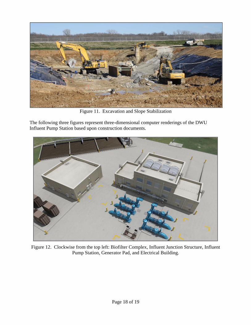
Figure 11. Excavation and Slope Stabilization
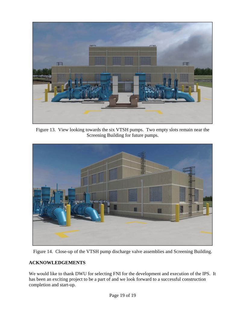
The following three figures represent three-dimensional computer renderings of the DWU Influent Pump Station based upon construction documents.
Figure 12. Clockwise from the top left: Biofilter Complex, Influent Junction Structure, Influent Pump Station, Generator Pad, and Electrical Building.
Page 19 of 19
Figure 13. View looking towards the six VTSH pumps. Two empty slots remain near the Screening Building for future pumps.
Figure 14. Close-up of the VTSH pump discharge valve assemblies and Screening Building. ACKNOWLEDGEMENTS We would like to thank DWU for selecting FNI for the development and execution of the IPS. It has been an exciting project to be a part of and we look forward to a successful construction completion and start-up.

TODAY’S COUPON:
425 MGD Pump Station at 30% OFF Erin Flanagan, P.E. – Freese and Nichols, Inc. Regina Stencel, P.E. – Dallas Water Utilities Bryan Jann, P.E. – Freese and Nichols, Inc. Texas Water 2012
April 12, 2012
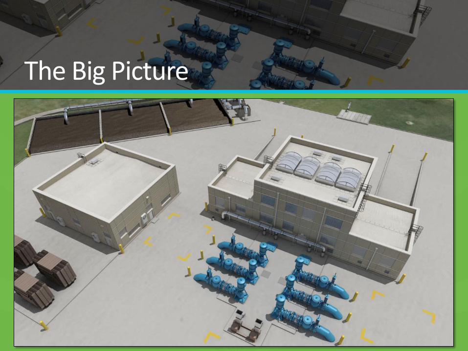
The Big Picture
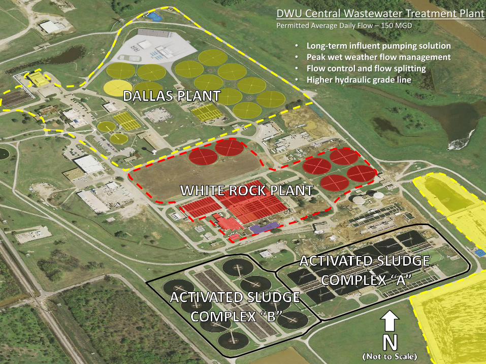
DWU Central Wastewater Treatment Plant Permitted Average Daily Flow – 150 MGD
• Long-term influent pumping solution • Peak wet weather flow management • Flow control and flow splitting • Higher hydraulic grade line
60” WEST BANK
42” FORCE MAIN
120” WEST BANK
INTERCEPTOR 84”
HORSESHOE
66” FORCE MAIN
& DRAIN LINES
84” HORSESHOE
72” CADIZ DIVERSION
KEYS TO SYMBOLS
EXISTING STRUCTURE
IPS STAGE 1 STRUCTURE IPS STAGE 1 LINE
EXISTING LINE
DECOMMISSIONED PUMP STATION
2 – 90” TO IPS
LEVEE JUNCTION
STRUCTURE
INFLUENT
PUMP STATION INFLUENT JUNCTION
STRUCTURE
SOUTH DALLAS
PEAK FLOW
PUMP STATION
WHITE ROCK
RAW SEWAGE
PUMP STATION
WHITE ROCK
PEAK FLOW
PUMP STATION PEAK FLOW
BASINS
CADIZ STREET
PUMP STATION
60” DIVERSION TO
WHITE ROCK PLANT
WHITE ROCK
PLANT
DALLAS
PLANT
WHITE ROCK
STRUCTURE
48” WARREN AVENUE
PEAK FLOW
BASINS
2 – 60” CADIZ FORCE MAIN
DECOMMISSIONED LINE
335
375
25
50
195
249
150
175
245
300
245
300 FIRM / TOTAL PUMPING CAPACITY
2 – 72” TO DALLAS PLANT
TO 120” WEST BANK
INTERCEPTOR
(BY OTHERS)
FUTURE
FACILITIES
IPS STAGE 2 LINE
(PROPOSED)
IPS STAGE 2 STRUCTURE
(PROPOSED)
S1 S2
425
465
Design Flow Determination • Minimum Flow
• Peak 2-hr Flow
• 0.31 (MFF)
• 2.89 (PF)
• 27 MGD minimum influent pumping at WRRSPS
Year
CWWTP
Minimum Hourly
Design Flow
(MGD)
CWWTP Average
Day Design Flow
(MGD)
CWWTP Peak 2-
hr Design Flow
(MGD)
2005 47 152 440
2010 52 166 481
2015 53 172 496
2020 55 178 513
2025 56 180 520
2030 57 183 528
Influent
Pump
Station
Minimum
Design Flow
(MGD)
Base Load
Flow (MGD)
Maximum
Pumping
Capacity
(MGD)
Maximum
Hydraulic
Capacity
(MGD)
Stage 1 20 55 335 375
Stage 2 20 55 425 465
Maximum Discharge Allocations
Discharge Location Stage 1
Stage 2
(Y2020/Y2025)
Dallas Plant 80 100
White Rock Diversion 60 60
Future Facilities 0 100
Peak Flow Basins* 150 150
* Allocations are MG
Pump Station Overall Section
Equipment Selection – Coarse Screens
COARSE SCREENING
EQUIPMENT
EVALUATION MATRIX
Chain
Type
(Conv)
Chain Type
(Catenary)
Cog
Wheel/Climber
Hydraulic
Telescoping Gripper Rope/Cable
Item
Wt
% Score Score Score Score Score Score
1 Capital Cost 20 0.60 0.60 0.60 0.60 1.40 0.60
2 Operation and
Maintenance 20 1.35 0.65 1.25 1.50 1.25 0.65
3 Space Requirements 20 1.52 1.12 1.28 1.12 1.28 1.52
4 Odor Control and
Cleanliness 15 0.89 0.68 0.89 0.15 0.15 0.68
5 Equipment Function 15 1.32 0.75 1.10 0.66 0.32 0.58
6 Constructability 10 0.80 0.50 0.80 0.35 0.35 0.55
Total 100 6.48 4.30 5.92 4.38 4.75 4.57
Multi-rake for peak flow Low Headroom requirement Positive DWU experience
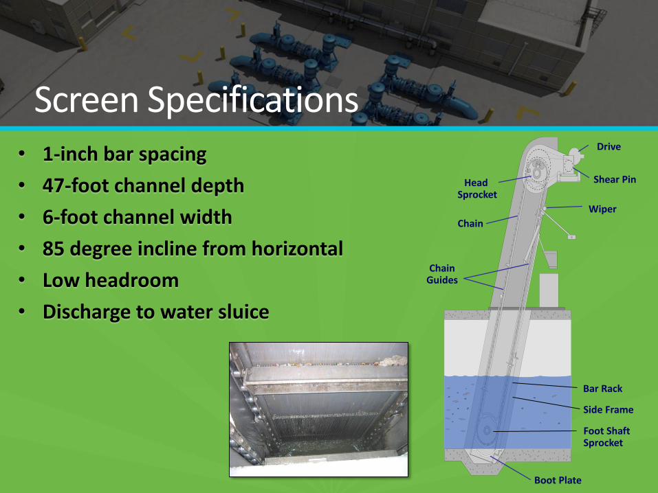
Screen Specifications • 1-inch bar spacing
• 47-foot channel depth
• 6-foot channel width
• 85 degree incline from horizontal
• Low headroom
• Discharge to water sluice
Chain Guides
Boot Plate
Chain
Shear Pin
Wiper
Drive
Bar Rack
Head Sprocket
Foot Shaft Sprocket
Side Frame
Equipment Selection - Pumps
PUMP EQUIPMENT
EVALUATION MATRIX Submersible
Vertical Turbine
(VTSH)
Horizontal
Centrifugal Vertical Centrifugal
Item Categor
y Wt% Score
Weighted
Score Score
Weighted
Score Score
Weighted
Score Score
Weighted
Score
1 Capital Cost 25 7 175 10 250 8 200 8 200
2 Maintenance 20 5 100 5 100 10 200 8 160
3 Ancillary Systems 15 8 120 10 150 7 105 8 120
4 Size of Pump Station 15 6 90 10 150 5 75 8 120
5 Applications 10 5 50 6 60 10 100 10 100
6 Energy Cost 10 7 70 10 100 9 90 9 90
7 Equipment Flood
Protection 5 10 50 10 50 2 10 10 50
Total 100 655 860 780 840
30% Cost Savings Above-grade
Maintenance Ease of Expansion
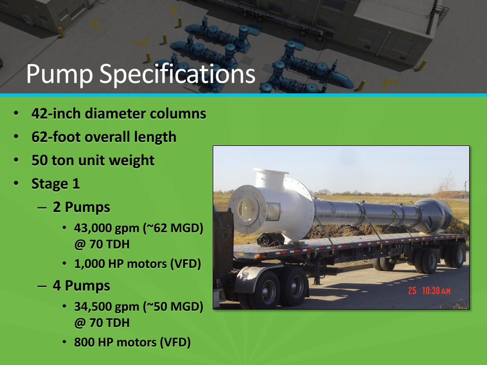
Pump Specifications • 42-inch diameter columns
• 62-foot overall length
• 50 ton unit weight
• Stage 1
– 2 Pumps • 43,000 gpm (~62 MGD)
@ 70 TDH
• 1,000 HP motors (VFD)
– 4 Pumps • 34,500 gpm (~50 MGD)
@ 70 TDH
• 800 HP motors (VFD)
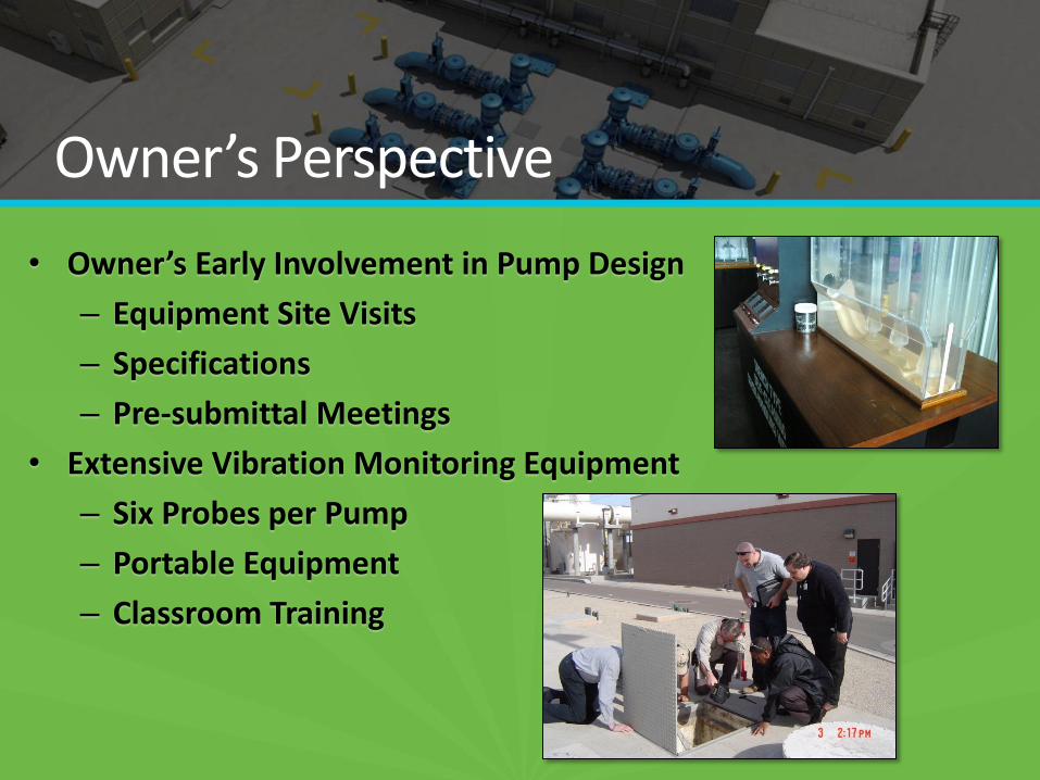
Owner’s Perspective
• Owner’s Early Involvement in Pump Design
– Equipment Site Visits
– Specifications
– Pre-submittal Meetings
• Extensive Vibration Monitoring Equipment
– Six Probes per Pump
– Portable Equipment
– Classroom Training
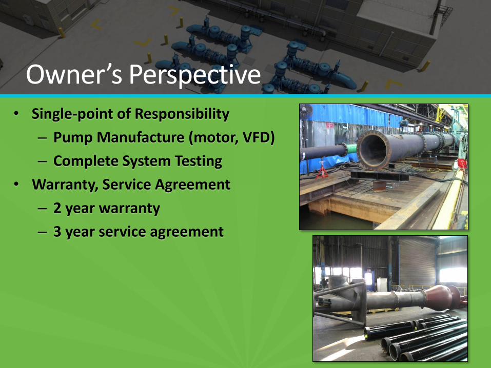
Owner’s Perspective • Single-point of Responsibility
– Pump Manufacture (motor, VFD)
– Complete System Testing
• Warranty, Service Agreement
– 2 year warranty
– 3 year service agreement
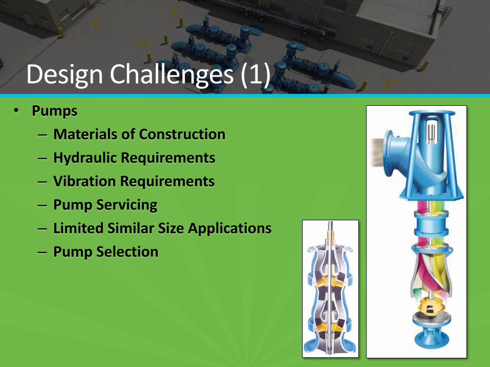
Design Challenges (1) • Pumps
– Materials of Construction
– Hydraulic Requirements
– Vibration Requirements
– Pump Servicing
– Limited Similar Size Applications
– Pump Selection
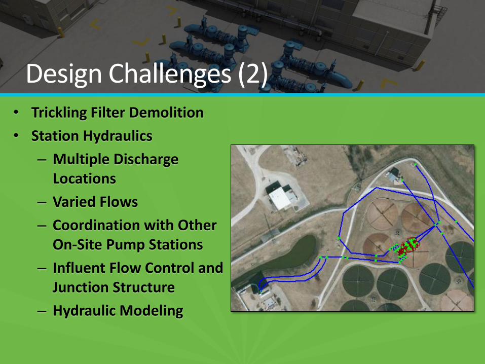
Design Challenges (2) • Trickling Filter Demolition
• Station Hydraulics
– Multiple Discharge Locations
– Varied Flows
– Coordination with Other On-Site Pump Stations
– Influent Flow Control and Junction Structure
– Hydraulic Modeling
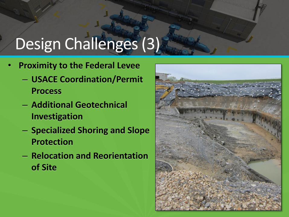
Design Challenges (3) • Proximity to the Federal Levee
– USACE Coordination/Permit Process
– Additional Geotechnical Investigation
– Specialized Shoring and Slope Protection
– Relocation and Reorientation of Site
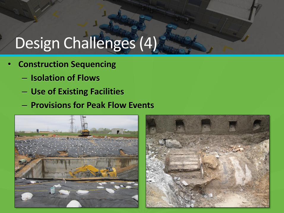
Design Challenges (4) • Construction Sequencing
– Isolation of Flows
– Use of Existing Facilities
– Provisions for Peak Flow Events
– Unforeseen Site Conditions
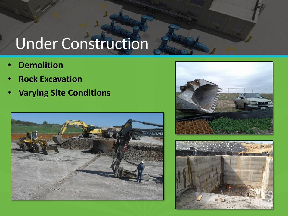
Under Construction • Demolition
• Rock Excavation
• Varying Site Conditions
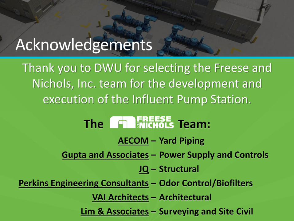
Acknowledgements Thank you to DWU for selecting the Freese and
Nichols, Inc. team for the development and execution of the Influent Pump Station.
The Team: Yard Piping
Power Supply and Controls
Structural
Odor Control/Biofilters
Architectural
Surveying and Site Civil
AECOM –
Gupta and Associates –
JQ –
Perkins Engineering Consultants –
VAI Architects –
Lim & Associates –
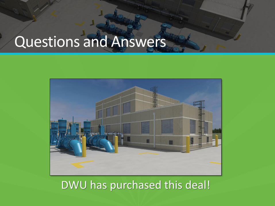
Questions and Answers
DWU has purchased this deal!