Embed Size (px)
DESCRIPTION
nx
Citation preview

Table of Contents
Dedication iiiPreface xvii
Chapter 1: Introduction to NX 8.5 Introduction to NX 8.5 1-2System Requirements 1-3Getting Started with NX 1-4Important Terms and Definitions 1-6Understanding the Functions of the Mouse Buttons 1-10Toolbars 1-11Hot Keys 1-17Color Scheme 1-17Dialog Boxes in NX 1-18Selecting Objects 1-19Deselecting Objects 1-19Selecting Objects Using the QuickPick Dialog Box 1-19Self-Evaluation Test 1-19
Chapter 2: Drawing Sketches for Solid ModelsThe Sketch task Environment 2-2Starting NX 8.5 2-2Starting a New Document in NX 8.5 2-4 Invoking Different NX Environments 2-7Creating Three Fixed Datum Planes (XC-YC, YC-ZC, XC-ZC) 2-7Displaying the WCS (Work Coordinate System) 2-8Creating Sketches 2-9 Creating Sketches in the Sketch task Environment 2-9 Creating Sketches in the Modeling Environment 2-15 Sketching Tools 2-15 Drawing Sketches Using the Profile Tool 2-15 Using Help Lines to Locate Points 2-19 Drawing Individual Lines 2-19 Drawing Arcs 2-19 Drawing Circles 2-21 Drawing Rectangles 2-22 Placing Points 2-24 Drawing Ellipses or Elliptical Arcs 2-28 Drawing Conics 2-30 Drawing Studio Splines 2-31
Eva
lua
tion
Cop
y. D
o no
t re
prod
uce.
For
inf
orm
ati
on v
isit
ww
w.c
adc
im.c
om

vi NX 8.5 for Designers Eva
lua
tion
Cop
y. D
o no
t re
prod
uce.
For
inf
orm
ati
on v
isit
ww
w.c
adc
im.c
om
Filleting Sketched Entities 2-33The Drawing Display Tools 2-35 Fitting Entities in the Current Display 2-35 Zooming an Area 2-35 Dynamic Zooming 2-36 Panning Drawings 2-36 Fitting View to Selection 2-37 Restoring the Original Orientation of the Sketching Plane 2-37Setting Selection Filters in the Sketch task Environment 2-37 Selecting Objects 2-39Deselecting Objects 2-39Using Snap Points Options While Sketching 2-39Deleting Sketched Entities 2-40Exiting the Sketch task Environment 2-40Tutorial 1 2-41Tutorial 2 2-44Tutorial 3 2-50Self-Evaluation Test 2-54Review Questions 2-55Exercise 1 2-56Exercise 2 2-56
Chapter 3: Adding Geometric and Dimensional Constraints to Sketches
Constraining Sketches 3-2Concept of Constrained Sketches 3-2 Under-Constrain 3-2 Fully-Constrain 3-2 Over-Constrain 3-2Degree of Freedom Arrows 3-3Dimensioning Sketches 3-4 Locking the Automatically Applied Dimensions of the Sketch 3-4 Applying Horizontal Dimensions 3-5 Applying Vertical Dimensions 3-5 Applying Parallel Dimensions 3-6 Applying Perpendicular Dimensions 3-7 Applying Angular Dimensions 3-8 Applying Diameter Dimensions 3-8 Applying Radius Dimensions 3-9 Applying Perimeter Dimensions 3-10 Applying Dimensions by Using the Inferred Dimensions Tool 3-10 Editing the Dimension Value and Other Parameters 3-11 Animating a Fully-Constrained Sketch 3-12Measuring the Distance Value between Objects in a Sketch 3-13 Measuring the Distance between Two Objects in a Sketch 3-14 Measuring the Projected Distance between Two Objects 3-15

Table of Contents vii
Eva
lua
tion
Cop
y. D
o no
t re
prod
uce.
For
inf
orm
ati
on v
isit
ww
w.c
adc
im.c
om
Measuring the Screen Distance between Two Objects 3-15 Measuring the Length of an Arc or a Line 3-16Measuring the Angle between Entities 3-16 Measuring the Angle Value Using the By Objects Option 3-16 Measuring the Angle Value Using the By 3 Points Option 3-17 Measuring the Angle Value Using the By Screen Points Option 3-18Geometric Constraints 3-18 Applying Additional Constraints Individually 3-19 Applying Symmetry constraint 3-25 Applying Automatic Constraints to a Sketch 3-25 Controlling Inferred Constraints Settings 3-27 Showing All Constraints in a Sketch 3-28 Showing/Removing Constraints 3-28 Converting a Sketch Entity or Dimension into a Reference Entity or Reference Dimension 3-30Tutorial 1 3-31Tutorial 2 3-37Tutorial 3 3-40Self-Evaluation Test 3-44Review Questions 3-44Exercise 1 3-45Exercise 2 3-46
Chapter 4: Editing, Extruding, and Revolving Sketches
Editing Sketches 4-2 Trimming Sketched Entities 4-2 Extending Sketched Entities 4-3 Creating a Corner between Sketched Entities 4-4 Offsetting Sketched Entities 4-5 Mirroring Sketched Entities 4-7 Creating Linear Sketch Pattern 4-8 Creating Circular Sketch Pattern 4-9 Copying, Moving, and Rotating Sketched Entities 4-10 Transforming Sketched Entities 4-15 Editing Sketched Entities by Dragging 4-19Exiting the Sketch task Environment 4-20Changing the View of the Sketch 4-20Creating Base Features by Extruding 4-20 Extrude Dialog Box Options 4-21Creating Solid Revolved Bodies 4-28Hiding Entities 4-33Showing Hidden Entities 4-34Hiding All Entities Using a Single Tool 4-34Rotating the View of a Model in 3D Space 4-35Setting Display Modes 4-36
viii NX 8.5 for Designers Eva
lua
tion
Cop
y. D
o no
t re
prod
uce.
For
inf
orm
ati
on v
isit
ww
w.c
adc
im.c
om
Tutorial 1 4-36Tutorial 2 4-39Tutorial 3 4-43Self-Evaluation Test 4-46Review Questions 4-47Exercise 1 4-48Exercise 2 4-48
Chapter 5: Working with Datum Planes, Coordinate Systems, and Datum Axes
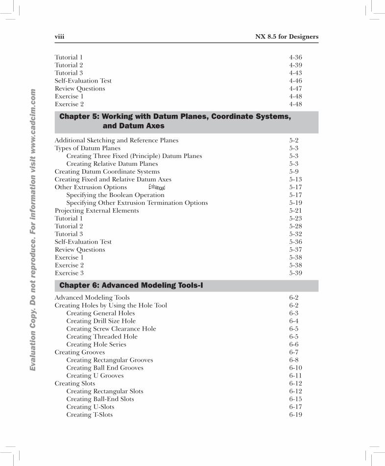
Additional Sketching and Reference Planes 5-2Types of Datum Planes 5-3 Creating Three Fixed (Principle) Datum Planes 5-3 Creating Relative Datum Planes 5-3Creating Datum Coordinate Systems 5-9Creating Fixed and Relative Datum Axes 5-13Other Extrusion Options 5-17 Specifying the Boolean Operation 5-17 Specifying Other Extrusion Termination Options 5-19Projecting External Elements 5-21Tutorial 1 5-23Tutorial 2 5-28Tutorial 3 5-32Self-Evaluation Test 5-36Review Questions 5-37Exercise 1 5-38Exercise 2 5-38 Exercise 3 5-39
Chapter 6: Advanced Modeling Tools-IAdvanced Modeling Tools 6-2Creating Holes by Using the Hole Tool 6-2 Creating General Holes 6-3 Creating Drill Size Hole 6-4 Creating Screw Clearance Hole 6-5 Creating Threaded Hole 6-5 Creating Hole Series 6-6Creating Grooves 6-7 Creating Rectangular Grooves 6-8 Creating Ball End Grooves 6-10 Creating U Grooves 6-11Creating Slots 6-12 Creating Rectangular Slots 6-12 Creating Ball-End Slots 6-15 Creating U-Slots 6-17 Creating T-Slots 6-19

Table of Contents ix
Eva
lua
tion
Cop
y. D
o no
t re
prod
uce.
For
inf
orm
ati
on v
isit
ww
w.c
adc
im.c
om
Creating Dove-Tail Slots 6-20Creating Chamfers 6-22 Creating a Chamfer Feature Using the Symmetric Method 6-23 Creating a Chamfer Feature Using the Asymmetric Method 6-25 Creating a Chamfer Feature Using the Offset and Angle Method 6-25Creating an Edge Blend 6-26Tutorial 1 6-31Tutorial 2 6-39Self-Evaluation Test 6-46Review Questions 6-47Exercise 1 6-48Exercise 2 6-48Exercise 3 6-49
Chapter 7: Advanced Modeling Tools-II
Advanced Modeling Tools 7-2Pattern Feature Tool 7-2 Creating Linear Pattern 7-2 Creating Circular Pattern 7-8 Creating Polygon Pattern 7-11 Creating Spiral Pattern 7-13 Creating a Pattern Along a Curve 7-14 Creating Reference Pattern 7-17 Creating a Fill Pattern 7-17Mirror Feature Tool 7-20Sweeping Sketches Along the Guide Curves 7-21Creating Swept Features 7-23Creating Tubes or Cables 7-26Creating Threads 7-27 Creating Symbolic Threads 7-28 Creating Detailed Threads 7-31Creating Shell Features 7-32 Shelling the Entire Solid Body 7-33 Tutorial 1 7-34Tutorial 2 7-37Tutorial 3 7-40Tutorial 4 7-45Self-Evaluation Test 7-51Review Questions 7-52Exercise 1 7-53Exercise 2 7-53

x NX 8.5 for Designers Eva
lua
tion
Cop
y. D
o no
t re
prod
uce.
For
inf
orm
ati
on v
isit
ww
w.c
adc
im.c
om
Chapter 8: Editing Features and Advanced Modeling Tools-III
Editing Features 8-2 Editing a Hole Feature 8-2 Editing the Positioning of a Groove Feature 8-2 Editing the Positioning of a Slot Feature 8-3 Editing the Parameters of Features 8-3 Editing the Parameters of Features with Rollback 8-3 Editing Sketches of the Sketch-based Features 8-3 Reordering Features 8-4Advanced Modeling Tools 8-4 Creating Boss Features 8-4 Creating Pocket Features 8-5 Creating Pad Features 8-9 Creating Drafts 8-12Tutorial 1 8-15Tutorial 2 8-19 Tutorial 3 8-27Self-Evaluation Test 8-34Review Questions 8-35Exercise 1 8-36Exercise 2 8-37Exercise 3 8-38
Chapter 9: Assembly Modeling-IThe Assembly Environment 9-2Invoking the Assembly Environment 9-2 Invoking the Assembly Environment Using the New Dialog Box 9-2 Invoking the Assembly Environment in the Current Part File 9-3 Types of Assembly Design Approaches 9-3Creating Bottom-up Assemblies 9-4 Placing Components in the Assembly Environment 9-4 Changing the Reference Set of a Component 9-7 Applying Assembly Constraints to Components 9-7 Points to Remember while Assembling Components 9-17 Creating a Component Array in an Assembly 9-17 Replacing a Component in an Assembly 9-20 Moving a Component in an Assembly 9-21 Mirroring a Component in an Assembly 9-25 Modifying a Component in the Assembly File 9-28Tutorial 1 9-29Tutorial 2 9-42Self-Evaluation Test 9-55Review Questions 9-56Exercise 1 9-56

Table of Contents xi
Eva
lua
tion
Cop
y. D
o no
t re
prod
uce.
For
inf
orm
ati
on v
isit
ww
w.c
adc
im.c
om
Exercise 2 9-58Exercise 3 9-61Exercise 4 9-64
Chapter 10: Assembly Modeling-IIThe Top-down Assembly Design Approach 10-2 Creating Components Using the Top-down Assembly Design Approach 10-2 Creating Subassemblies 10-4 Editing Assembly Constraints 10-5 Modifying the Assembly Constraints 10-5Checking the Interference between the Components of an Assembly 10-6 Checking Interference Using the Simple Interference Tool 10-6 Checking Interference and Clearance Using the Check Clearance Analysis 10-8 Checking Interference Using the Assembly Clearance Method 10-9 Checking Interference and Clearance, and Analyzing Cross-sections of Components Using the View Section Tool 10-15Creating Exploded Views of an Assembly 10-20 Exploding Views Automatically 10-21 Exploding Views Manually 10-22Tutorial 1 10-24Tutorial 2 10-28Tutorial 3 10-33Tutorial 4 10-39Self-Evaluation Test 10-44Review Questions 10-45Exercise 1 10-46
Chapter 11: Surface Modeling Introduction to Surface Modeling 11-2Invoking the Shape Studio Environment 11-2 Creating an Extruded Surface 11-3 Creating a Revolved Surface 11-3 Creating a Ruled Surface 11-4 Creating a Surface Using the Through Curves Tool 11-6 Creating a Surface Using the Through Curve Mesh Tool 11-8 Creating a Surface Using the Four Point Surface Tool 11-10 Creating a Swoop Surface 11-10 Creating Planar Surfaces from 2D Sketches and Edges of Solid or Surface 11-12 Creating a Transition Surface Using the Transition Tool 11-13 Creating an N-Sided Surface 11-15 Creating a Silhouette Flange Surface 11-18 Extending a Surface Using the Law Extension Tool 11-22 Creating a Surface Offset Using the Offset Surface Tool 11-26 Trimming and Extending a Surface Using the Trim and Extend Tool 11-27 Trimming a Sheet by Using the Trimmed Sheet Tool 11-28 Creating a Surface Using the Studio Surface Tool 11-30 Creating a Surface between Two Walls Using the Styled Blend Tool 11-33

xii NX 8.5 for Designers Eva
lua
tion
Cop
y. D
o no
t re
prod
uce.
For
inf
orm
ati
on v
isit
ww
w.c
adc
im.c
om
Creating Surfaces Using the Styled Sweep Tool 11-38 Sewing Individual Surfaces into a Single Surface 11-39 Adding Thickness to a Surface 11-40 Adding Drafts 11-41Tutorial 1 11-43Tutorial 2 11-48Self-Evaluation Test 11-56Review Questions 11-56Exercise 1 11-57Exercise 2 11-58
Chapter 12: Advanced Surface ModelingCreating Curves from Bodies 12-2 Creating Intersection Curves 12-2 Creating Section Curves 12-3 Creating Extract Curves 12-8 Creating Isoparametric Curves 12-10 Projecting Curves 12-12Advanced Surface Modeling Tools 12-15 Creating Dart Features 12-15 Creating Emboss Body on a Sheet or Solid Body 12-17 Creating Face Blend Features 12-18 Creating Soft Blend Features 12-23 Creating Bridge Features 12-26Tutorial 1 12-27Tutorial 2 12-38Tutorial 3 12-47Self-Evaluation Test 12-59Review Questions 12-59Exercise 1 12-60Exercise 2 12-61
Chapter 13: Generating, Editing, and Dimensioning the Drawing Views
The Drafting Environment 13-2Invoking the Drafting Environment 13-2 Invoking the Drafting Environment Using the Drawing Template from the New Dialog Box 13-2 Invoking the Drafting Environment in the Current Part File 13-3Editing the Drawing Sheet Parameters in the Drafting Environment 13-6Invoking the Drafting Tools 13-6Types of Drawing Views in NX 13-6 Base View 13-6 Projected View 13-7 Detail View 13-7 Section View 13-7 Auxiliary View 13-7

Table of Contents xiii
Eva
lua
tion
Cop
y. D
o no
t re
prod
uce.
For
inf
orm
ati
on v
isit
ww
w.c
adc
im.c
om
Half-Section View 13-7 Revolved Section View 13-7 Break-Out Section View 13-7 Broken View 13-7Generating Drawing Views 13-8 Generating Views Using the View Creation Wizard Tool 13-8 Generating the Base View 13-13 Generating the Orthographic Drawing Views Using the Projected View Tool 13-16 Generating the Detail View Using the Detail View Tool 13-17 Generating Section Views Using the Section View Tool 13-21 Generating the Half Section View Using the Half Section View Tool 13-25 Generating the Revolved Section View 13-26 Generating the Break-Out Section View 13-27 Generating the Broken View 13-28Manipulating the Drawing Views 13-30 Aligning the Drawing Views Using the Align View Tool 13-30 View Boundary 13-32 Displaying the Model Using the Display Sheet Tool 13-34 Inserting a Drawing Sheet Using the New Sheet Tool 13-34Modifying the Properties of a Generated Drawing View 13-34 Modifying the Scale Value of the Drawing View 13-34Adding Dimensions to the Drawing Views 13-36 Retrieving Dimensions from the Model 13-36 Adding Dimensions to the Drawing View 13-37Generating Exploded Views of an Assembly 13-40Creating Parts List and Associative Balloons 13-40 Creating a Parts List for an Assembly 13-41 Creating Associative Balloons 13-41 Creating a Tabular Note (Title Block) 13-43Adding Multiline Text to a Drawing Sheet 13-44Printing Tools 13-45 Print 13-45 Plot 13-46Tutorial 1 13-47Tutorial 2 13-52Tutorial 3 13-58Self-Evaluation Test 13-65Review Questions 13-66Exercise 1 13-67Exercise 2 13-68
Chapter 14: Synchronous ModelingIntroduction 14-2 Move Face 14-2 Pull Face 14-5 Offset Region 14-7

xiv NX 8.5 for Designers Eva
lua
tion
Cop
y. D
o no
t re
prod
uce.
For
inf
orm
ati
on v
isit
ww
w.c
adc
im.c
om
Replace Face 14-8 Resize Blend 14-9 Reorder Blend 14-9 Resize Chamfer 14-10 Label Chamfer 14-10 Label Notch Blend 14-11 Resize Face 14-11 Delete Face 14-12 Copy Face 14-14 Cut Face 14-15 Paste Face 14-16 Mirror Face 14-17 Pattern Face 14-17 Make Coplanar 14-18 Make Coaxial 14-19 Make Tangent 14-20 Make Symmetric 14-21 Make Parallel 14-22 Make Perpendicular 14-23 Make Fixed 14-24 Make Offset 14-25 Show Related Face 14-26 Linear Dimension 14-26 Angular Dimension 14-28 Radial Dimension 14-29 Shell Body 14-31 Shell Face 14-32 Change Shell Thickness 14-33 Group Face 14-34 Edit Cross Section in History Free Mode 14-34 Edit Cross Section in History Mode 14-36Tutorial 1 14-36Tutorial 2 14-42Self-Evaluation Test 14-51Review Questions 14-52Exercise 1 14-53Exercise 2 14-53
Chapter 15: Sheet Metal DesignThe Sheet Metal Module 15-2Setting the Sheet Metal Part Properties 15-4Creating the Base feature 15-7Adding Flanges to a Sheet Metal Part 15-8Creating Contour Flanges 15-15

Table of Contents xv
Eva
lua
tion
Cop
y. D
o no
t re
prod
uce.
For
inf
orm
ati
on v
isit
ww
w.c
adc
im.c
om
Creating Lofted Flanges 15-16Adding a Jog to the Sheet 15-17Bending the Sheet Metal Part 15-18Unbending the Sheet Metal Part 15-19Rebending the Sheet Metal Part 15-19Filleting or Chamfering Corners 15-19Closing the Corners of a Sheet Metal Part 15-20Creating Dimples in a Sheet Metal Part 15-24Creating Louvers in a Sheet Metal Part 15-27Creating Drawn Cutouts in a Sheet Metal Part 15-28Creating Beads in a Sheet Metal Part 15-29Adding Gussets to a Sheet Metal part 15-32Adding Hems 15-35Creating a Sheet Metal Part using Solid body 15-39Converting a Solid Part Into a Sheet Metal Part 15-39Ripping the Corners of a Solid Part 15-41Creating the Flat Pattern of a Sheet Metal Part 15-41 Creating the Flat Pattern 15-41 Creating the Flat Solid 15-42 Exporting a Flat Pattern 15-43Tutorial 1 15-43Tutorial 2 15-53Self-Evaluation Test 15-59Review Questions 15-59Exercise 1 15-60Exercise 2 15-62
Index 1