Embed Size (px)
Citation preview

Valve terminals VTOC
TOC BookmarkValve terminals VTOC Overview – Valve terminals
Characteristics
Peripherals overview
Characteristics – Pneumatic components
Characteristics – Display and operation
Characteristics – Electrical components
Data sheet – Valve terminal VTOC with multi-pin plug connection
Technical data
Data sheet – Valve terminal VTOC with I-Port interface, interlock/IO-Link
Technical data
Dimensions
Accessories
Solenoid valves
Cover plate
Blanking plug
Connecting cable for multi-pin plug
Inscription label holder
Push-in fittings
Silencer
Ordering data – CTEU
Bus node
Bus connection
Electrical connection block
Connecting cable
Plug socket
Inscription label

2 d Internet: www.festo.com/catalogue/... Subject to change – 2021/10
Valve terminal VTOC
Overview – Valve terminals
Design type Typecode
Description a Page/Internet
Valve terminal VTOC with multi-pin plug connection, Sub-DSD • Sub-D 25-pin
• Sub-D 44-pin29
Valve terminal VTOC with multi-pin plug connection, ribbon cableRC • Ribbon cable, 26-pin
• Ribbon cable, 40-pin• Ribbon cable, 50-pin
29
Valve terminal with I-Port interface, interlock/IO-LinkLK/PT • I-Port interface: plug M12, 5-pin
• Sub-D 44-pin • IO-Link
31
Overview – Valve terminals

32021/10 – Subject to change d Internet: www.festo.com/catalogue/...
Valve terminal VTOC
Characteristics
Innovative Flexible Reliable Easy to install
• Valve terminal for a wide range of pneumatic applications
• Weight-optimised metal manifold rail
• Space-saving thanks to 2x3/2-way valves on one valve position
• Great flexibility during planning, assembly and operation
• Configurable manifold rails (pneu-matic and electric connections)
• Provides 2 ... 24 valve positions on one terminal
• Flexibility of the pneumatic working ports provides a practical solution to different requirements
• Wide range of electrical outlet directions
• Multi-pin plug connection with Sub-D plug or ribbon cable
• I-Port interface with interlock for bus node (CTEU)
• IO-Link mode for direct connection to a higher-level IO-Link master
• Manual override – non-detenting, non-detenting/detenting, detenting
• Long service life • Sturdy thanks to simple design
• Ready-to-install and tested unit• Reduced ordering, assembly and
commissioning costs• Easy valve assembly
H- - Note
Ordering system for valve terminal VTOCa Internet: vtoc
Characteristics

4 d Internet: www.festo.com/catalogue/... Subject to change – 2021/10
Valve terminal VTOC
Characteristics – Valve terminals
Valve terminal with multi-pin plug connection
16
4
5
32
7
[1] Simple electrical connections: ribbon cable or Sub-D
[2] Valve with manual override, detenting, non-detenting
[3] Valve with manual override, non-detenting
[4] Valve with manual override, detenting
[5] Valve width 10 mm[6] Choice of pneumatic outlets: QS
push-in connectors, straight or angled
[7] Space-saving thanks to 2x3/2-way valves
Valve terminal with I-Port interface, interlock/IO-Link
6
4
5
32
1
7
[1] I-Port interface with interlock/IO-Link
[2] Valve with manual override, detenting, non-detenting
[3] Valve with manual override, non-detenting
[4] Valve with manual override, detenting
[5] Valve width 10 mm[6] Choice of pneumatic outlets: QS
push-in connectors, straight or angled
[7] Space-saving thanks to 2x3/2-way valves
Equipment optionsValve functions Electrical connection options
• 2x3/2-way valve, single solenoid, normally closed
• Valve with manual override, non-detenting
• Valve with manual override, detenting, non-detenting
• Valve with manual override, detenting
• 2 ... 24 valve positions/ max. 48 solenoid coils
• Variable multi-pin plug connection: Sub-D or ribbon cable
• I-Port interface with interlock for bus node (CTEU)
• IO-Link mode for direct connection to a higher-level IO-Link master

52021/10 – Subject to change d Internet: www.festo.com/catalogue/...
Valve terminal VTOC
Characteristics
Integration of the I-Port interface/IO-Link
Different bus nodes are used for integration into the control systems of various manufacturers.
The following protocols are supported with the compatible bus node CTEU:• CANopen• DeviceNet
• EtherCAT• CC-Link• Profibus
Use of the electrical connection block CAPC permits decentralised installa-tion of bus nodes CTEU on a further valve terminal or input modules with I-Port interfaces (a installation system CTEU/CTEL)
System overview, example
7
3
9
8
6
5
4
10
1
2
[1] Fieldbus[2] IO-Link/ I-Port[3] PLC[4] Bus node CTEU (I-Port master) on
electrical connection block CAPC[5] Valve terminal VTOC, I-Port
interface with bus node CTEU[6] CPX terminal with bus node and
CTEL master[7] Valve terminal CPV with I-Port
interface/IO-Link[8] Input module CTSL[9] Pneumatic drive with sensor[10] Pneumatic drive
• Communication with the higher- order controller via fieldbus
• Use a bus node CTEU compatible with the fieldbus protocol
• Up to 64 inputs/outputs (solenoid coils), depending on the valve terminal

6 d Internet: www.festo.com/catalogue/... Subject to change – 2021/10
Valve terminal VTOC
Peripherals overview
Overview – Valve terminal VTOC with multi-pin plug connection, Sub-D
• Up to 24 valve positions/ 48 solenoid coils
• Connection type: ribbon cable, code: RC
• Connection type: Sub-D plug, code: SD
Valve terminals with electrical multi- pin plug connection are available with 2 to max. 24 valve positions. Each valve position can either be equipped with a valve body or a cover plate.
Only valve bodies containing two 3/2-way single solenoid valves are available.
A maximum of 48 solenoid coils can therefore be actuated via the electrical multi-pin plug connection.
16
1
5
3
7146
8
10
13
4
9
2
6
7
8
9
10
12
11
15
Peripherals overview

72021/10 – Subject to change d Internet: www.festo.com/catalogue/...
Valve terminal VTOC
Peripherals overview
AccessoriesType Brief description a Page/
Internet
[1] Connecting cable KMP6/NEBV
For multi-pin plug connection, with Sub-D plug, 25-pin or 44-pin 41
[2] Solenoid valve, single solenoid VOVC With manual override, non-detenting 41[3] Solenoid valve, single solenoid VOVC With manual override, detenting, non-detenting 41[4] Cover plate VABB For vacant position 41[5] Inscription label holder ASCF For labelling the valves/covering the manual override 42[6] Silencer U For mounting in exhaust ports 42[7] Elbow connector QSL For connecting to the air supply or exhaust 42[8] T-fitting QST For connecting to the air supply or exhaust 42[9] Straight fitting OS For connecting to the air supply or exhaust 42[10] Blanking plug B For sealing the air supply or exhaust port 41[11] Push-in L-fitting, long QSMLLV Long elbow connector for working ports 42[12] Push-in L-fitting QSMLV Elbow connector for working ports 42[13] Push-in fitting QS Straight push-in fitting for working ports 42[14] Push-in fitting QSIMG Straight countersunk push-in fitting for working ports (compact) –[15] Manifold rail VABB With multi-pin plug connection for max. 24 valve positions –[16] Cover VAMC For manual override, detenting (without accessories) 41

8 d Internet: www.festo.com/catalogue/... Subject to change – 2021/10
Valve terminal VTOC
Peripherals overview
Overview – Valve terminal VTOC with I-Port interface, interlock/IO-Link
• Up to 24 valve positions/ 48 solenoid coils
• Connection type: I-Port interface with interlock code: PT
• Code: LK
The electrical supply/transmission of communication takes place via an M12 plug.The valve terminal can be equipped with 2 ... 24 valves.
Only valve bodies containing two single solenoid 3/2-way valves are available.
The following protocols are supported in connection with the associated CTEU bus node:• DeviceNet• CANopen• Profibus DP• EtherCAT• CC-Link
1
18
16
1112
13
1415
2019
17
15
14
13
11
21
12
22
4
237
2
3
4
5
6
10
8
9
24

92021/10 – Subject to change d Internet: www.festo.com/catalogue/...
Valve terminal VTOC
Peripherals overview
AccessoriesType Brief description a Page/
Internet
[1] Connecting cable KMP6/NEBV
For multi-pin plug connection, with Sub-D plug, 44-pin 41
[2] Plug socket NEFF For bypassing the interlock function 44[3] Inscription label holder ASCF For labelling the valves/covering the manual override 42[4] Fieldbus CTEU Bus node 43[5] Plug socket FBSD/
NTSDFor bus node CTEU 44
[6] Plug SEA Straight, for T-adapter FB-TA 44[7] T adapter FB-TA For IO-Link and load supply 44[8] Solenoid valve, single solenoid VOVC With manual override, non-detenting 41[9] Solenoid valve, single solenoid VOVC With manual override, detenting, non-detenting 41[10] Cover plate VABB For vacant position 41[11] Silencer U For mounting in exhaust ports 42[12] Elbow connector QSL For connecting to the air supply or exhaust 42[13] T-fitting QST For connecting to the air supply or exhaust 42[14] Straight fitting OS For connecting to the air supply or exhaust 42[15] Blanking plug B For sealing the air supply or exhaust port 41[16] Push-in L-fitting, long QSMLLV Long elbow connector for working ports 42[17] Push-in L-fitting QSMLV Elbow connector for working ports 42[18] Push-in fitting QS Straight, for working ports 42[19] Push-in fitting QSIMG Straight countersunk push-in fitting for working ports (compact) –[20] Manifold rail VABB With I-Port interface/IO-Link, interlock –[21] H-rail mounting CAFM For electrical connection block CAPC 44[22] Electrical connection block CAPC For connecting a second device with I-Port interface 44[23] Connecting cable NEBU – 44[24] Cover VAMC For manual override, detenting (without accessories) 41
10 d Internet: www.festo.com/catalogue/... Subject to change – 2021/10
Valve terminal VTOC
Peripherals overview
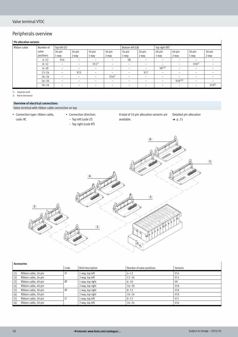
Pin allocation variants
Ribbon cable Number of valve positions
Top left (LT) Bottom left (LB) Top right (RT)26-pin1-way
26-pin2-way
50-pin1-way
50-pin2-way
26-pin1-way
26-pin2-way
40-pin1-way
40-pin2-way
50-pin1-way
50-pin2-way
4–12 V14 – – – V8 – – – – –8–12 – – V111) – – – – – V101) –6–10 – – – – – – V91)2) – – –
13–24 – V15 – – – V17 – – – –16–24 – – – V161) – – – – – –16–20 – – – – – – – V181)2) – –18–24 – – – – – – – – – V191)
1) Separate earth
2) Not bi-directional
Overview of electrical connectionsValve terminal with ribbon cable connection on top
• Connection type: ribbon cable, code: RC
• Connection direction:– Top left (code LT)– Top right (code RT)
A total of 10 pin allocation variants are available.
Detailed pin allocation a p. 21
2
4
6
3
5
1
AccessoriesCode Brief description Number of valve positions Variants
[1] Ribbon cable, 26-pin LT 1-way, top left 4–12 V14[2] Ribbon cable, 26-pin 2-way, top left 13–24 V15[3] Ribbon cable, 40-pin RT 1-way, top right 6–10 V9[4] Ribbon cable, 40-pin 2-way, top right 16–20 V18[5] Ribbon cable, 50-pin RT 1-way, top right 8–12 V10[6] Ribbon cable, 50-pin 2-way, top right 18–24 V19[5] Ribbon cable, 50-pin LT 1-way, top left 8–12 V11[6] Ribbon cable, 50-pin 2-way, top left 16–24 V16

112021/10 – Subject to change d Internet: www.festo.com/catalogue/...
Valve terminal VTOC
Peripherals overview
Overview of electrical connectionsValve terminal with ribbon cable connection underneath
• Connection type: ribbon cable, code: RC
• Connection direction:– Bottom left (code LB)
A total of 10 pin allocation variants are available.
Detailed pin allocation a p. 21
2
1
AccessoriesCode Brief description Number of valve positions Variants
[1] Ribbon cable, 26-pin LB 1-way, bottom left 4–12 V8[2] Ribbon cable, 26-pin 2-way, bottom left 13–24 V17

12 d Internet: www.festo.com/catalogue/... Subject to change – 2021/10
Valve terminal VTOC
Peripherals overview
Pin allocation variants
Sub-D Number of valve positions
Top left (LT) Top right (RT)25-pin, 1-way 25-pin, 2-way 25-pin, 2-way 44-pin, 1-way 44-pin, 2-way 44-pin, 1-way
2–12 V2 V32) V1 – – – – – –4–12 – – – – V121) – – – –
13–21 – – – – – V5 – – V1313–22 – – – – – – V71) V61)2) –13–24 – – – V4 – – – – –
1) Separate earth
2) Not bi-directional
Overview of electrical connectionsValve terminal with Sub-D connection on top
• Connection type: Sub-D code: SD
Connection direction:• Top left (code LT)• Top right (code RT)
A total of 9 pin allocation variants are available.
Detailed pin allocation a p. 18
5
3
4
1
2
AccessoriesCode Brief description Number of valve positions Variants
[1] Sub-D 25-pin LT 1-way, top left 2...12 V1, V2, V3[2] Sub-D 25-pin 2-way, top left 13...24 V4
4...12 V12[3] Sub-D 44-pin LT 1-way, top left 13...21 V5[4] Sub-D 44-pin 2-way, top left 13...22 V6, V7[5] Sub-D 44-pin RT 1-way, top right 13...20 V13

132021/10 – Subject to change d Internet: www.festo.com/catalogue/...
Valve terminal VTOC
Characteristics – Pneumatic components
Design
The valves are mounted on the metal manifold rail using two screws. The use of 2x3/2-way valves per valve position guarantees optimum use of space with maximum performance.
The valves only differ in the type of manual override. The assembled and tested units or individual components as modules enable a custom configuration.
Cover plates can be replaced by valves at a later date.
The existing dimensions, mounting points and the pneumatic and electrical installation do not change.
Valve functionCode Circuit symbol Width Description
10 mm
K h 2x3/2-way valve, single solenoid• Reset via mechanical spring• Not reversible
Characteristics – Pneumatic components

14 d Internet: www.festo.com/catalogue/... Subject to change – 2021/10
Valve terminal VTOC
Characteristics – Pneumatic components
Fittings Ports 1/3
Wide range of connection sizes:• Threaded connection M7, G1/8,
1/8 NPT• Push-in connector QS6, QS8, QS3/8
or QS1/4 (compressed air supply)• Push-in connector QS6, QS1/4 or
silencer (exhaust air)
Choice of connection types for port 1, compressed air supply and port 3, exhaust air:• Straight• Elbow connector• T-fitting
Flexible connection positions for the compressed air supply and exhaust:• At both ends• Left• Right
Ports 1/3Connection direction: front Code Description
-G18 Manifold block G1/8(diagram shows example of Sub-D electrical connection on left)Basis for design:• Push-in connector QS8• Push-in connector QS3/8"
-M7 Manifold block M7(diagram shows example of Sub-D electrical connection on left)Basis for design:• Push-in connector QS6• Push-in connector QS1/4"• Exhaust port via push-in fitting or silencer

152021/10 – Subject to change d Internet: www.festo.com/catalogue/...
Valve terminal VTOC
Characteristics – Pneumatic components
Fittings Ports 2/4
Wide range of connection sizes:• Threaded connection M5• 10-32 UNF• Push-in connector QS3, QS4 or 1/8"
Outlet direction:• At front• At bottom
Connection on the valve (port 2/4)Outlet direction at front Code Description
1 2 3 4 5
[1] X Straight countersunk outlet (compact)[2] – Straight outlet[3] FB Angled outlet, upwards/downwards[4] FA Angled outlet, upwards[5] FC Angled outlet, downwards
Outlet direction underneath
1 2 3 54[1] X Straight countersunk outlet (compact)[2] U Straight outlet[3] UB Angled outlet, to the front/rear[4] UA Angled outlet, to the front[5] UC Angled outlet, to the rear

16 d Internet: www.festo.com/catalogue/... Subject to change – 2021/10
Valve terminal VTOC
Characteristics – Display and operation
Manual override (MO)Manual override with automatic return (non-detenting)
1 2[1] Press in the stem of the manual
override with a pointed object or screwdriver. The valve switches.
[2] Remove the pointed object or screwdriver. Spring force pushes the manual override back. The valve returns to its normal position.
Manual override with lock (non-detenting/detenting)
1 2[1] Press in the stem of the manual
override with a screwdriver until the valve switches and then turn the stem clockwise by 90° until the stop is reached. The valve remains switched.
[2] Turn the stem anticlockwise by 90° until the stop is reached and then remove the screwdriver. Spring force pushes the manual override back. Valve returns to normal position.
H- - Note
VTOC provides two valves with the same valve function but different types of manual override. There is no provision for subsequent modifica-tion of the type of manual override (e.g. by attaching a cover).
Inscription system
1
2
1 2
1
[1] Retaining bracket for inscription label holder The retaining bracket for the in-scription label holder is mounted on the valves using a screw. It enables the inscription label holder to be mounted in two dif-ferent directions. The retainers at the side are flanged. to prevent the inscription label sliding out.
[2] Inscription label holder A transparent inscription label holder ASCF-H-L2 (code F/T in the order code) can be mounted for labelling the valves. Inscription labels can be inserted in the holder for labelling purpos-es. Templates for printing the in-scription label are available on request.
Mounting – Valve terminal
Sturdy terminal mounting via:• Four through-holes for wall mounting
(hole 3.3 mm @)• Four holes with thread on the reverse
side:– Thread M3– Thread M4
– Thread 8-32 UNC– Thread 10-32 UNC-2B
Characteristics – Display and operation

172021/10 – Subject to change d Internet: www.festo.com/catalogue/...
Valve terminal VTOC
Characteristics – Electrical components
Electrical connection Multi-pin plug
The following multi-pin plug connec-tions are available for the valve terminal VTOC:• Sub-D multi-pin plug connection
(25-pin, 1-way or 2-way)• Sub-D multi-pin plug connection
(44-pin, 1-way or 2-way)• Ribbon cable connector
(26-pin, 1-way or 2-way)• Ribbon cable connector
(40-pin, 1-way or 2-way)• Ribbon cable connector
(50-pin, 1-way or 2-way)
The multi-pin plug connection is avail-able with 19 different pin allocation variants.Other variants on request.Connection directions:Sub-D connection (top left/right)Ribbon cable (top/bottom left, top/bottom right)
Signals from the controller to the valve terminal are transmitted via the mul-ti-core pre-assembled cable, which substantially reduces installation time.
The valves are switched by means of positive or negative logic (positive switching or negative switching). Mixed operation is not permitted. Each pin on the multi-pin plug can actuate exactly one solenoid coil. If the maximum con-figurable number of valve positions is 24, this means that 48 solenoid coils can be addressed.
Explanation of pin allocation (V12)
The example shows the pin allocation code V12. The solenoid coils are wired in ascending order of the valves so that solenoid coil 14 occupies the low-val-ue pin and solenoid coil 12 the next pin of both Sub-D connections:
• Pin 1 of Sub-D A and Sub-D B at valve position 1, coil 14.
• Pin 2 of Sub-D A and Sub-D B at valve position 1, coil 12.
The following tables show the different pin allocation variants.
The circuitry may differ from the exam-ple depending on the multi-pin plug connection chosen.
Characteristics – Electrical components

18 d Internet: www.festo.com/catalogue/... Subject to change – 2021/10
Valve terminal VTOC
Characteristics – Electrical components
Pin allocation – Sub-D plug, 25-pinPin -V1 -V2 -V3 -V4 -V12
Sub-D A1) Sub-D B2) Sub-D A1) Sub-D B2)
1 VP1 12 VP1 14 VP1 14- VP1 14 VP13 14 VP1 14 VP1 142 VP1 14 VP2 14 VP2 14- VP1 12 VP13 12 VP1 12 VP1 123 VP2 12 VP3 14 VP3 14- VP2 14 VP14 14 VP2 14 VP2 144 VP2 14 VP4 14 VP4 14- VP2 12 VP14 12 VP2 12 VP2 125 VP3 12 VP5 14 VP5 14- VP3 14 VP15 14 VP3 14 VP3 146 VP3 14 VP6 14 VP6 14- VP3 12 VP15 12 VP3 12 VP3 127 VP4 12 VP7 14 VP7 14- VP4 14 VP16 14 VP4 14 VP4 148 VP4 14 VP8 14 VP8 14- VP4 12 VP16 12 VP4 12 VP4 129 VP5 12 VP9 14 VP9 14- VP5 14 VP17 14 VP5 14 VP5 1410 VP5 14 VP10 14 VP10 14- VP5 12 VP17 12 VP5 12 VP5 1211 VP6 12 VP11 14 VP11 14- VP6 14 VP18 14 VP6 14 VP6 1412 VP6 14 VP12 14 VP12 14- VP6 12 VP18 12 VP6 12 VP6 1213 VP7 12 Com Com+ VP7 14 VP19 14 VP7 14 VP7 1414 VP7 14 VP1 12 VP1 12- VP7 12 VP19 12 VP7 12 VP7 1215 VP8 12 VP2 12 VP2 12- VP8 14 VP20 14 VP8 14 VP8 1416 VP8 14 VP3 12 VP3 12- VP8 12 VP20 12 VP8 12 VP8 1217 VP9 12 VP4 12 VP4 12- VP9 14 VP21 14 VP9 14 VP9 14
18 VP9 14 VP5 12 VP5 12- VP9 12 VP21 12 VP9 12 VP9 1219 VP10 12 VP6 12 VP6 12- VP10 14 VP22 14 VP10 14 VP10 1420 VP10 14 VP7 12 VP7 12- VP10 12 VP22 12 VP10 12 VP10 12
H- - Note
The drawing shows a plan view of the Sub-D plug on the valve terminal.
21 VP11 12 VP8 12 VP8 12- VP11 14 VP23 14 VP11 14 VP11 1422 VP11 14 VP9 12 VP9 12- VP11 12 VP23 12 VP11 12 VP11 1223 VP12 12 VP10 12 VP10 12- VP12 14 VP24 14 VP12 14 VP12 1424 VP12 14 VP11 12 VP11 12- VP12 12 VP24 12 VP12 12 VP12 1225 Com VP12 12 VP12 12- Com 1-12 Com 13-24 – – – –
VP Valve position1) Sub-D A, first Sub-D plug2) Sub-D B, second Sub-D plug

192021/10 – Subject to change d Internet: www.festo.com/catalogue/...
Valve terminal VTOC
Characteristics – Electrical components
Pin allocation – Sub-D plug, 44-pinPin -V5 -V6 -V7 -V13
Sub-D A1) Sub-D B2) Sub-D A1) Sub-D B2)
1 VP1 14 VP1 14+ VP1 14- VP1 14 VP1 14 VP1 122 VP1 12 VP1 12+ VP1 12- VP1 12 VP1 12 VP1 143 VP2 14 VP2 14+ VP2 14- VP2 14 VP2 14 VP2 124 VP2 12 VP2 12+ VP2 12- VP2 12 VP2 12 VP2 145 VP3 14 VP3 14+ VP3 14- VP3 14 VP3 14 VP3 126 VP3 12 VP3 12+ VP3 12- VP3 12 VP3 12 VP3 147 VP4 14 VP4 14+ VP4 14- VP4 14 VP4 14 VP4 128 VP4 12 VP4 12+ VP4 12- VP4 12 VP4 12 VP4 149 VP5 14 VP5 14+ VP5 14- VP5 14 VP5 14 VP5 1210 VP5 12 VP5 12+ VP5 12- VP5 12 VP5 12 VP5 1411 VP6 14 VP6 14+ VP6 14- VP6 14 VP6 14 VP6 1212 VP6 12 VP6 12+ VP6 12- VP6 12 VP6 12 VP6 1413 VP7 14 VP7 14+ VP7 14- VP7 14 VP7 14 VP7 1214 VP7 12 VP7 12+ VP7 12- VP7 12 VP7 12 VP7 1415 VP8 14 VP8 14+ VP8 14- VP8 14 VP8 14 VP8 1216 VP8 12 VP8 12+ VP8 12- VP8 12 VP8 12 VP8 1417 VP9 14 VP9 14+ VP9 14- VP9 14 VP9 14 VP9 1218 VP9 12 VP9 12+ VP9 12- VP9 12 VP9 12 VP9 1419 VP10 14 VP10 14+ VP10 14- VP10 14 VP10 14 VP10 1220 VP10 12 VP10 12+ VP10 12- VP10 12 VP10 12 VP10 1421 VP11 14 VP11 14+ VP11 14- VP11 14 VP11 14 VP11 1222 VP11 12 VP11 12+ VP11 12- VP11 12 VP11 12 VP11 1423 VP12 14 VP12 14+ VP12 14- VP12 14 VP12 14 VP12 1224 VP12 12 VP12 12+ VP12 12- VP12 12 VP12 12 VP12 1425 VP13 14 VP13 14+ VP13 14- VP13 14 VP13 14 VP13 1226 VP13 12 VP13 12+ VP13 12- VP13 12 VP13 12 VP13 1427 VP14 14 VP14 14+ VP14 14- VP14 14 VP14 14 VP14 1228 VP14 12 VP14 12+ VP14 12- VP14 12 VP14 12 VP14 1429 VP15 14 VP15 14+ VP15 14- VP15 14 VP15 14 VP15 1230 VP15 12 VP15 12+ VP15 12- VP15 12 VP15 12 VP15 1431 VP16 14 VP16 14+ VP16 14- VP16 14 VP16 14 VP16 1232 VP16 12 VP16 12+ VP16 12- VP16 12 VP16 12 VP16 1433 VP17 14 VP17 14+ VP17 14- VP17 14 VP17 14 VP17 1234 VP17 12 VP17 12+ VP17 12- VP17 12 VP17 12 VP17 1435 VP18 14 VP18 14+ VP18 14- VP18 14 VP18 14 VP18 1236 VP18 12 VP18 12+ VP18 12- VP18 12 VP18 12 VP18 1437 VP19 14 VP19 14+ VP19 14- VP19 14 VP19 14 VP19 1238 VP19 12 VP19 12+ VP19 12- VP19 12 VP19 12 VP19 1439 VP20 14 VP20 14+ VP20 14- VP20 14 VP20 14 VP20 12
H- - Note
The drawing shows a plan view of the Sub-D plug on the valve terminal.
40 VP20 12 VP20 12+ VP20 12- VP20 12 VP20 12 VP20 1441 VP21 14 VP21 14+ VP21 14- VP21 14 VP21 14 Com42 VP21 12 VP21 12+ VP21 12- VP21 12 VP21 12 Com43 Com VP22 14+ VP22 14- VP22 14 VP22 14 Com44 Com VP22 12+ VP22 12- VP22 12 VP22 12 Com
VP Valve position1) Sub-D A, first Sub-D plug2) Sub-D B, second Sub-D plug

20 d Internet: www.festo.com/catalogue/... Subject to change – 2021/10
Valve terminal VTOC
Characteristics – Electrical components
Electrical connection
The solenoid coils are wired in ascend-ing order of the valves so that solenoid coil 14 occupies the low-value pin and solenoid coil 12 the next pin:
• Pin 1 of ribbon cable 1 valve position 1, coil 14.
• Pin 2 of ribbon cable 1 valve position 1, coil 12.
The valve positions are evenly divided between the two ribbon cable connectors.If there is an odd number of valve posi-tions, plug 2 controls one more valve position than plug 1.
The following table shows the pin allocation variants.
Pin allocation – Ribbon cable, 26-pinValve positions -V15 -V17Total No. Pin Pin
[1] Plug 1 [2] Plug 2 [1] Plug 1 [2] Plug 2
1
2
13 1 ... 6 1 ... 12 – 12 ... 1 –7 ... 13 – 1 ... 14 – 14 ... 1Com 25 ... 26 25 ... 26 25 ... 26 25 ... 26
14 1 ... 7 1 ... 14 – 14 ... 1 –8 ... 14 – 1 ... 14 – 14 ... 1Com 25 ... 26 25 ... 26 25 ... 26 25 ... 26
15 1 ... 8 1 ... 14 – 14 ... 1 –8 ... 15 – 1 ... 16 – 16 ... 1Com 25 ... 26 25 ... 26 25 ... 26 25 ... 26
16 1 ... 8 1 ... 16 – 16 ... 1 –9 ... 16 – 1 ... 16 – 16 ... 1Com 25 ... 26 25 ... 26 25 ... 26 25 ... 26
17 1 ... 8 1 ... 16 – 16 ... 1 –9 ... 17 – 1 ... 18 – 18 ... 1Com 25 ... 26 25 ... 26 25 ... 26 25 ... 26
18 1 ... 9 1 ... 18 – 18 ... 1 –10 ... 18 – 1 ... 18 – 18 ... 1Com 25 ... 26 25 ... 26 25 ... 26 25 ... 26
19 1 ... 9 1 ... 18 – 18 ... 1 –10 ... 19 – 1 ... 20 – 20 ... 1Com 25 ... 26 25 ... 26 25 ... 26 25 ... 26
20 1 ... 10 1 ... 20 – 20 ... 1 –11 ... 20 – 1 ... 20 – 20 ... 1Com 25 ... 26 25 ... 26 25 ... 26 25 ... 26
21 1 ... 10 1 ... 20 – 20 ... 1 –11 ... 21 – 1 ... 22 – 22 ... 1Com 25 ... 26 25 ... 26 25 ... 26 25 ... 26
22 1 ... 11 1 ... 22 – 22 ... 1 –12 ... 22 – 1 ... 22 – 22 ... 1Com 25 ... 26 25 ... 26 25 ... 26 25 ... 26
23 1 ... 11 1 ... 22 – 22 ... 1 –
12 ... 23 – 1 ... 24 – 24 ... 1
H- - Note
The drawing shows a plan view of the ribbon cable connector on the valve terminal.
Com 25 ... 26 25 ... 26 25 ... 26 25 ... 2624 1 ... 12 1 ... 24 – 24 ... 1 –
13 ... 24 – 1 ... 24 – 24 ... 1Com 25 ... 26 25 ... 26 25 ... 26 25 ... 26

212021/10 – Subject to change d Internet: www.festo.com/catalogue/...
Valve terminal VTOC
Characteristics – Electrical components
Pin allocation – Ribbon cable, 26-pinPin -V8 -V14
1 VP12 14 VP1 142 VP12 12 VP1 123 VP11 14 VP2 144 VP11 12 VP2 125 VP10 14 VP3 146 VP10 12 VP3 127 VP9 14 VP4 148 VP9 12 VP4 129 VP8 14 VP5 1410 VP8 12 VP5 1211 VP7 14 VP6 1412 VP7 12 VP6 1213 VP6 14 VP7 1414 VP6 12 VP7 1215 VP5 14 VP8 1416 VP5 12 VP8 1217 VP4 14 VP9 1418 VP4 12 VP9 1219 VP3 14 VP10 1420 VP3 14 VP10 1421 VP2 14 VP11 14
H- - Note
The drawing shows a plan view of the ribbon cable connector on the valve terminal.
22 VP2 12 VP11 1223 VP1 14 VP12 1424 VP1 12 VP12 1225 Com Com26 Com Com
VP Valve position

22 d Internet: www.festo.com/catalogue/... Subject to change – 2021/10
Valve terminal VTOC
Characteristics – Electrical components
Electrical connection
The solenoid coils are wired in ascend-ing order of the valves so that solenoid coil 14 occupies the two higher-value pins and solenoid coil 12 the next two pins:
• Pin 40 and 39 of ribbon cable 1 valve position 1, coil 14.
• Pin 38 and 37 of ribbon cable 1 valve position 1, coil 12.
The valve positions are evenly divided between the two ribbon cable connectors.If there is an odd number of valve posi-tions, plug 2 controls one more valve position than plug 1.
The following table shows the pin allocation variants.
Pin allocation – Ribbon cable, 40-pinPin -V18
[1] Plug 1 [2] Plug 2Number of valve positions 16 17 18 19 20 16 17 18 19 20
1
21 VP8 VP8 VP9 VP9 VP10 VP16 VP17 VP18 VP19 VP202 VP8 VP8 VP9 VP9 VP10 VP16 VP17 VP18 VP19 VP203 VP8 VP8 VP9 VP9 VP10 VP16 VP17 VP18 VP19 VP204 VP8 VP8 VP9 VP9 VP10 VP16 VP17 VP18 VP19 VP205 VP7 VP7 VP8 VP8 VP9 VP15 VP16 VP17 VP18 VP196 VP7 VP7 VP8 VP8 VP9 VP15 VP16 VP17 VP18 VP197 VP7 VP7 VP8 VP8 VP9 VP15 VP16 VP17 VP18 VP198 VP7 VP7 VP8 VP8 VP9 VP15 VP16 VP17 VP18 VP199 VP6 VP6 VP7 VP7 VP8 VP14 VP15 VP16 VP17 VP1810 VP6 VP6 VP7 VP7 VP8 VP14 VP15 VP16 VP17 VP1811 VP6 VP6 VP7 VP7 VP8 VP14 VP15 VP16 VP17 VP1812 VP6 VP6 VP7 VP7 VP8 VP14 VP15 VP16 VP17 VP1813 VP5 VP5 VP6 VP6 VP7 VP13 VP14 VP15 VP16 VP1714 VP5 VP5 VP6 VP6 VP7 VP13 VP14 VP15 VP16 VP1715 VP5 VP5 VP6 VP6 VP7 VP13 VP14 VP15 VP16 VP1716 VP5 VP5 VP6 VP6 VP7 VP13 VP14 VP15 VP16 VP1717 VP4 VP4 VP5 VP5 VP6 VP12 VP13 VP14 VP15 VP1618 VP4 VP4 VP5 VP5 VP6 VP12 VP13 VP14 VP15 VP1619 VP4 VP4 VP5 VP5 VP6 VP12 VP13 VP14 VP15 VP1620 VP4 VP4 VP5 VP5 VP6 VP12 VP13 VP14 VP15 VP1621 VP3 VP3 VP4 VP4 VP5 VP11 VP12 VP13 VP14 VP1522 VP3 VP3 VP4 VP4 VP5 VP11 VP12 VP13 VP14 VP1523 VP3 VP3 VP4 VP4 VP5 VP11 VP12 VP13 VP14 VP1524 VP3 VP3 VP4 VP4 VP5 VP11 VP12 VP13 VP14 VP1525 VP2 VP2 VP3 VP3 VP4 VP10 VP11 VP12 VP13 VP14
26 VP2 VP2 VP3 VP3 VP4 VP10 VP11 VP12 VP13 VP14
27 VP2 VP2 VP3 VP3 VP4 VP10 VP11 VP12 VP13 VP14
28 VP2 VP2 VP3 VP3 VP4 VP10 VP11 VP12 VP13 VP14
29 VP1 VP1 VP2 VP2 VP3 VP9 VP10 VP11 VP12 VP13
30 VP1 VP1 VP2 VP2 VP3 VP9 VP10 VP11 VP12 VP13
31 VP1 VP1 VP2 VP2 VP3 VP9 VP10 VP11 VP12 VP13
32 VP1 VP1 VP2 VP2 VP3 VP9 VP10 VP11 VP12 VP13
33 – – VP1 VP1 VP2 – VP9 VP10 VP11 VP12
34 – – VP1 VP1 VP2 – VP9 VP10 VP11 VP12
35 – – VP1 VP1 VP2 – VP9 VP10 VP11 VP12
H- - Note
The drawing shows a plan view of the ribbon cable connector on the valve terminal.
36 – – VP1 VP1 VP2 – VP9 VP10 VP11 VP1237 – – – – VP1 – – – VP10 VP1138 – – – – VP1 – – – VP10 VP1139 – – – – VP1 – – – VP10 VP1140 – – – – VP1 – – – VP10 VP11
VP Valve position

232021/10 – Subject to change d Internet: www.festo.com/catalogue/...
Valve terminal VTOC
Characteristics – Electrical components
Pin allocation – Ribbon cable, 40-pinPin -V9
1 VP10 12+2 VP10 12-3 VP10 14+4 VP10 14-5 VP9 12+6 VP9 12-7 VP9 14+8 VP9 14-9 VP8 12+10 VP8 12-11 VP8 14+12 VP8 14-13 VP7 12+14 VP7 12-15 VP7 14+16 VP7 14-17 VP6 12+18 VP6 12-19 VP6 14+20 VP6 14-21 VP5 12+22 VP5 12-23 VP5 14+24 VP5 14-25 VP4 12+26 VP4 12-27 VP4 14+28 VP4 14-29 VP3 12+30 VP3 12-31 VP3 14+32 VP3 14-33 VP2 12+34 VP2 12-35 VP2 14+
H- - Note
The drawing shows a plan view of the ribbon cable connector on the valve terminal.
36 VP2 14-37 VP1 12+38 VP1 12-39 VP1 14+40 VP1 14-
VP Valve position

24 d Internet: www.festo.com/catalogue/... Subject to change – 2021/10
Valve terminal VTOC
Characteristics – Electrical components
Electrical connection
The solenoid coils are wired in ascend-ing order of the valves so that solenoid coil 14 occupies the two higher-value pins and solenoid coil 12 the two low-value pins:
Variant -V16:• Pin 1 and 2 of ribbon cable 1 valve
position 1, coil 12.• Pin 3 and 4 of ribbon cable 1 valve
position 1, coil 14.
Variant -V19:• Pin 48 and 47 of ribbon cable 1
valve position 1, coil 14.• Pin 46 and 45 of ribbon cable 1
valve position 1, coil 12.The valve positions are evenly divided between the two ribbon cable connectors.
If there is an odd number of valve posi-tions, plug 2 controls one more valve position than plug 1.
The following table shows the pin allocation variants.
Pin allocation – Ribbon cable, 50-pinValve positions -V16 -V19Total No. Pin Pin
[1] Plug 1 [2] Plug 2 [1] Plug 1 [2] Plug 2
1
2
18 1 ... 9 1 ... 36 – 48 ... 13 –
10 ... 18 – 1 ... 36 – 48 ... 13
19 1 ... 9 1 ... 36 – 48 ... 13 –
10 ... 19 – 1 ... 40 – 48 ... 9
20 1 ... 10 1 ... 40 – 48 ... 9 –
11 ... 20 – 1 ... 40 – 48 ... 9
21 1 ... 10 1 ... 40 – 48 ... 9 –
11 ... 21 – 1 ... 44 – 48 ... 5
22 1 ... 11 1 ... 44 – 48 ... 5 –
12 ... 22 – 1 ... 44 – 48 ... 5
23 1 ... 11 1 ... 44 – 48 ... 5 –
12 ... 23 – 1 ... 48 – 48 ... 1
H- - Note
The drawing shows a plan view of the ribbon cable connector on the valve terminal.
24 1 ... 12 1 ... 48 – 48 ... 1 –
13 ... 24 – 1 ... 48 – 48 ... 1

252021/10 – Subject to change d Internet: www.festo.com/catalogue/...
Valve terminal VTOC
Characteristics – Electrical components
Pin allocation – Ribbon cable, 50-pinPin -V11 -V10
1 VP1 12 VP12 122 VP1 12 VP12 123 VP1 14 VP12 144 VP1 14 VP12 145 VP2 12 VP11 126 VP2 12 VP11 127 VP2 14 VP11 148 VP2 14 VP11 149 VP3 12 VP10 1210 VP3 12 VP10 1211 VP3 14 VP10 1412 VP3 14 VP10 1413 VP4 12 VP9 1214 VP4 12 VP9 1215 VP4 14 VP9 1416 VP4 14 VP9 1417 VP5 12 VP8 1218 VP5 12 VP8 1219 VP5 14 VP8 1420 VP5 14 VP8 1421 VP6 12 VP7 1222 VP6 12 VP7 1223 VP6 14 VP7 1424 VP6 14 VP7 1425 VP7 12 VP6 1226 VP7 12 VP6 1227 VP7 14 VP6 1428 VP7 14 VP6 1429 VP8 12 VP5 1230 VP8 12 VP5 1231 VP8 14 VP5 1432 VP8 14 VP5 1433 VP9 12 VP4 1234 VP9 12 VP4 1235 VP9 14 VP4 1436 VP9 14 VP4 1437 VP10 12 VP3 1238 VP10 12 VP3 1239 VP10 14 VP3 1440 VP10 14 VP3 1441 VP11 12 VP2 1242 VP11 12 VP2 1243 VP11 14 VP2 1444 VP11 14 VP2 1445 VP12 12 VP1 1246 VP12 12 VP1 12
H- - Note
The drawing shows a plan view of the ribbon cable connector on the valve terminal.
47 VP12 14 VP1 1448 VP12 14 VP1 144950
VP Valve position

26 d Internet: www.festo.com/catalogue/... Subject to change – 2021/10
Valve terminal VTOC
Characteristics – Electrical components
I-Port interface with interlock/IO-LinkIO-Link I-Port Interlock
IO-Link is an interface that supplies data for communication in addition to the power supply. An IO-Link system consists of an IO-Link master and IO-Link devices. The IO-Link master acts as the interface to the higher-order controller (PLC) and controls communication with the con-nected IO-Link devices. One device with IO-Link (e.g. an IO-Link valve ter-minal from Festo) can be connected to each port on an IO-Link master.
The Festo-specific I-Port interface based on IO-Link offers the following connection options:• Directly at the fieldbus, by mounting
a bus node CTEU• Connection to a higher-order I-Port
master from Festo
The interlock function enables the first 16 solenoid coils to be individually supplied externally. This guarantees the safe release of these valves.The interlock interface is established via external contacts for a single-pin connection or via safety output termi-nals for a double-pin connection.
For applications that do not require ac-tuation of the solenoid coils via inter-lock, the Sub-D connection can be by-passed using a special Sub-D socket (NEFF…).The solenoid coils are then supplied with load voltage via the I-Port interface.
Overview
1
54
3
2
[1] PLC[2] Fieldbus[3] Bus node CTEU (I-Port master)[4] Valve terminal VTOC, I-Port
interface with interlock/IO-Link[5] Valve terminal VTOC, I-Port
interface/IO-Link with Sub-D socket NEFF

272021/10 – Subject to change d Internet: www.festo.com/catalogue/...
Valve terminal VTOC
Characteristics – Electrical components
Interlock interfaceSingle-pin interlock interface Double-pin interlock interface
• The interlock interface is estab-lished via external positive switch-ing contacts or single-pin switching safety terminals
• 16 solenoid coils can be actuated via the interlock (Vn+)
• Solenoid coils that do not require interlock actuation can be supplied directly with 24 V from pins 1 ... 3
• Application of the respective input voltage is reported via the fieldbus as a process image
• The interlock interface is estab-lished via external positive-negative switching safety terminals
• The solenoid coils of the interlock valves are actuated via the corre-sponding pins in the sub-D plug (pins 7 ... 38)
• The solenoid coils that do not re-quire interlock actuation can be supplied directly with 24 V (e.g. from pins 1 ... 3)
• Any difference in potential between Vn– and 0 V VAL/OUT must be below 5 V
Sample circuit diagram for a single-pin interlock interface
7
65
12
3
4
98
10
11
15
14
13
12
[1] Power supply V+; solenoid coil 33 ... 48 (no interlock)
[2] Power supply V+; solenoid coil 17 ... 32 (no interlock)
[3] Actuation Vn+ (via interlock)[4] Interlock contacts of the output
terminal[5] I-Port connection pin 2, 24 V VAL/
OUT (PL), load voltage supply[6] I-Port connection pin 5, 0 V VAL/
OUT (PL), load voltage supply[7] Driver, actuated via fieldbus/
I-Port[8] Interlock Sub-D connection[9] Power supply (interlock)
[10] 24 V VAL [12] V 16+ [14] V 1–
[11] 0 V VAL [13] V 1+ [15] V 16–

28 d Internet: www.festo.com/catalogue/... Subject to change – 2021/10
Valve terminal VTOC
Characteristics – Electrical components
Sample circuit diagram for a double-pin interlock interface
8
76
9 10
12
3
5
1314
15
16
18
17
12
11
4
[1] Power supply V+; solenoid coil 33 ... 48 (no interlock)
[2] Power supply V+; solenoid coil 17 ... 32 (no interlock)
[3] Actuation Vn+ (via interlock)[4] Interlock contacts of the output
terminal[5] Actuation Vn– (via interlock)[6] I-Port connection pin 2, 24 V VAL/
OUT (PL), load voltage supply[7] I-Port connection pin 5, 0 V VAL/
OUT (PL), load voltage supply[8] Driver, actuated via fieldbus/
I-Port[9] Interlock Sub-D connection[10] Power supply (interlock)
[11] 24 V VAL [13] V 16+ [15] V 1+ [17] V 2–
[12] 0 V VAL [14] V 2+ [16] V 1– [18] V 16–
Pin allocation – InterlockPin Coil Signal Pin Coil Signal Pin Coil Signal
1 – 24 VVAL/OUT 16 5 V5- 31 13 V13+2 – 24 VVAL/OUT 17 6 V6+ 32 13 V13-3 – 24 VVAL/OUT 18 6 V6- 33 14 V14+4 1 ... 48 0 VVAL/OUT 19 7 V7+ 34 14 V14-5 1 ... 48 0 VVAL/OUT 20 7 V7- 35 15 V15+6 1 ... 48 0 VVAL/OUT 21 8 V8+ 36 15 V15-7 1 V1+ 22 8 V8- 37 16 V16+8 1 V1- 23 9 V9+ 38 16 V16-9 2 V2+ 24 9 V9- 39 17 ... 32 V17...32+10 2 V2- 25 10 V10+ 40 33 ... 48 V33...48+11 3 V3+ 26 10 V10- 41 1 ... 48 0 VVAL/OUT
12 3 V3- 27 11 V11+ 42 1 ... 48 0 VVAL/OUT
13 4 V4+ 28 11 V11- 43 1 ... 48 0 VVAL/OUT
14 4 V4- 29 12 V12+ 44 – n.c.15 5 V5+ 30 12 V12- Housing FE
Pin allocation – I-Port interface/IO-LinkPin Allocation Function
1 24VEL/SEN (PS) Operating voltage supply (electronics, sensors/inputs)2 24VVAL/OUT (PL) Load voltage supply (valves/outputs)3 0VEL/SEN (PS) Operating voltage supply (electronics, sensors/inputs)4 C/Q Data communication5 0VVAL/OUT (PL) Load voltage supply (valves/outputs)Housing, FE Functional earth

292021/10 – Subject to change d Internet: www.festo.com/catalogue/...
Valve terminal VTOC
Data sheet – Valve terminal VTOC with multi-pin plug connection
-P- Voltage 24 V DC
-L- Pressure 0 ... +8 bar
-Q- Temperature range –5 ... +50°C
General technical data
Valve function 2x3/2-way valve, closed, single solenoidDesign Poppet valve with spring returnOverlap Negative overlapSealing principle SoftActuation type ElectricReset method Mechanical springType of control DirectFlow direction Non-reversibleExhaust air function Cannot be throttledManual override Non-detenting, detenting and non-detenting, detenting (without accessories)Type of mounting Via through-hole or threadMounting position AnyWidth [mm] 10Nominal width [mm] 0.65Max. no. of valve positions 24Standard nominal flow rate qnN [l/min] 10Product weight Valve [g] 30
Cover plate for vacant position [g] 20Corrosion resistance class1) 1
1) Corrosion resistance class CRC 1 according to Festo standard FN 940070
Low corrosion stress. Dry internal application or transport and storage protection. Also applies to parts behind covers, in the non-visible interior area, or parts which are covered in the application (e.g. drive trunnions).
Operating and environmental conditions
Operating medium Compressed air to ISO 8573-1:2010 [7:4:4]Note on operating/pilot medium Lubricated operation possible (in which case lubricated operation will always be required)Operating pressure [bar] 0 ... +8Ambient temperature [°C] –5 ... +50Temperature of medium [°C] –5 ... +50Housing material Reinforced PASealing material NBR
PUNote on materials RoHS-compliantCE marking To EU EMC DirectiveKC mark KC EMCCertification c UL us - Recognized (OL)
*
Data sheet – Valve terminal VTOC with multi-pin plug connection
Technical data

30 d Internet: www.festo.com/catalogue/... Subject to change – 2021/10
Valve terminal VTOC
Data sheet – Valve terminal VTOC with multi-pin plug connection
Electrical data
Electrical control Multi-pin plug (Sub-D/ribbon cable)Nominal operating voltage [V DC] 24Permissible voltage fluctuations [%] ±10Pick-up time [ms] 100Nominal pick-up current per solenoid coil (current consumption per coil during pick-up phase)
[mA] 55 to 100 ms
Nominal current with current reduction (current consumption per coil during holding phase)
[mA] 13 after 100 ms
Degree of protection to EN 60529 IP40Signal status display LED
Valve switching times[ms]
On 5.2Off 4.7
Safety data
Well-tried component YesMax. positive test pulse with 0 signal [µs] 600Max. negative test pulse with 1 signal [µs] 800Shock resistance Shock test at severity level 2, to FN 942017-5 and EN 60068-2-27Vibration resistance Transport application test at severity level 2, to FN 942017-4 and EN 60068-2-6

312021/10 – Subject to change d Internet: www.festo.com/catalogue/...
Valve terminal VTOC
Data sheet – Valve terminal VTOC with I-Port interface, interlock/IO-Link
-P- Voltage 24 V DC
-L- Pressure 0 ... +8 bar
-Q- Temperature range –5 ... +50°C
General technical data
Valve 2x3/2 normally closed, reset via mechanical springDesign Poppet valve with spring returnOverlap Negative overlapReset method Mechanical springType of control DirectFlow direction Non-reversibleExhaust air function Cannot be throttledManual override Non-detenting, detenting and non-detenting, detenting (without accessories)Types of communication I-Port/IO-LinkNumber of valve positions 2 ... 24Max. number of solenoid coils 48Number of interlock solenoid coils 16Number of inputs for voltage feedback 18 (16x interlock + 2 group supply)Mounting position AnyNominal flow rate [l/min] 10Residual ripple [VSS] 4Baud rate COM3 [kbps] 230.4
COM2 [kbps] 38.4IO-Link Protocol V1.0
Connection technology M12, A-codedPort type Type BNumber of ports 1Process data width OUT 6 bytesProcess data width IN 4 bytesMinimum cycle time 11.5 ms (2.3 ms per frame = 2 bytes of user data)
Product weight Valve [g] 30Cover plate for vacant position [g] 20
Corrosion resistance class1) 1
1) Corrosion resistance class CRC 1 according to Festo standard FN 940070
Low corrosion stress. Dry internal application or transport and storage protection. Also applies to parts behind covers, in the non-visible interior area, or parts which are covered in the application (e.g. drive trunnions).
Operating and environmental conditions
Operating medium Compressed air to ISO 8573-1:2010 [7:4:4]Note on operating/pilot medium Lubricated operation possible (in which case lubricated operation will always be required)Operating pressure [bar] 0 ... +8Ambient temperature [°C] –5 ... +50Housing material Reinforced PASealing material NBR
PUNote on materials RoHS-compliantCE marking To EU EMC DirectiveKC mark KC EMCCertification c UL us - Recognized (OL)
*
Data sheet – Valve terminal VTOC with I-Port interface, interlock/IO-Link
Technical data

32 d Internet: www.festo.com/catalogue/... Subject to change – 2021/10
Valve terminal VTOC
Data sheet – Valve terminal VTOC with I-Port interface, interlock/IO-Link
Electrical data
Power supply Load voltage interlock (valves) [V DC] 24 (±10%)Load voltage (valves) [V DC] 24 (±10%)Operating voltage (electronics) [V DC] 24 (±25%)
Duration of pick-up phase [ms] 100Current consumption per coil at 24 V during pick-up phase (valves) [mA] 55Current consumption per coil at 24 V during holding phase (valves) [mA] 13Intrinsic current consumption via I-Port (valves/electronics) [mA] 40/30Degree of protection to EN 60529 IP40
*
Valve switching times[ms]
On 5.2Off 4.7
Safety data
Well-tried component YesMax. positive test pulse with 0 signal [µs] 600Max. negative test pulse with 1 signal [µs] 800Shock resistance Shock test at severity level 2, to FN 942017-5 and EN 60068-2-27Vibration resistance Transport application test at severity level 2, to FN 942017-4 and EN 60068-2-6

332021/10 – Subject to change d Internet: www.festo.com/catalogue/...
Valve terminal VTOC
Data sheet – Valve terminal VTOC
Dimensions – Sub-D, single or double Download CAD data a www.festo.com
[1] Ports 1 and 3, left and right, M7 or G1/8
[2] Ports 2 and 4, front or under-neath, M5 or 10-32 UNF
[3] Centre of first valve position[4] Inscription label[5] Electrical connection via Sub-D,
single or double (left or right)
Comment Electrical connection on top, single Electrical connection on top, double
Pneumatic connection – M7 G1/8 G1/8 M7 G1/8 G1/8Through-hole – @ 3.3 @ 3.3 M4 @ 3.3 @ 3.3 M4
L1 – L2+L3+L4 L2+L3+L4 L2+L3+L4 L2+L3+L4 L2+L3+L4 L2+L3+L4L2 – (n-1)x10.5 (n-1)x10.5 (n-1)x10.5 (n-1)x10.5 (n-1)x10.5 (n-1)x10.5L3 Distance from centre of first valve position
to outer edge on left-hand side41.4 46.4 36.9 66.4 71.4 66.4
Sub-D connection, 44-pin, top right, 1-way:Distance from centre of first valve position to outer edge on left-hand side
14.4 20.4 20.4 – – –
L4 Distance from centre of last valve position to outer edge on right-hand side
14.4 20.4 20.4 – – –
Sub-D connection, 44-pin, top right, 1-way:Distance from centre of last valve position to outer edge on right-hand side
41.4 46.4 36.9 – – –
L5 – (L1-6) (L1-6) (L1-6) (L1-6) (L1-6) (L1-6)
B1 B2± 0.1
B3± 0.1
H1 H2 H3 H4 H5 H6 L6 L7± 0.1
L8
57 28.9 25.9 57.9 52.3 20 23.1 14.5 5 10.5 3 2.9
Dimensions

34 d Internet: www.festo.com/catalogue/... Subject to change – 2021/10
Valve terminal VTOC
Data sheet – Valve terminal VTOC
Dimensions – Ribbon cable on top Download CAD data a www.festo.com
[1] Ports 1 and 3, left and right, M7 or G1/8
[2] Ports 2 and 4, front or under-neath, M5 or 10-32 UNF
[3] Centre of first valve position[6] Electrical connection via ribbon
cable
Comment Electrical connection via ribbon cable on top
Pneumatic connection – M7 G1/8 G1/8Through-hole – @ 3.3 @ 3.3 M4
L1 – L2+L3+L4 L2+L3+L4 L2+L3+L4L2 – (n-1)x10.5 (n-1)x10.5 (n-1)x10.5L3 Distance from centre of first valve position to
outer edge on left-hand side14.4 46.4 36.9
L4 Distance from centre of last valve position to outer edge on right-hand side
14.4 20.4 20.4
L5 – (L1-6) (L1-6) (L1-6)
B1 B2± 0.1
B3± 0.1
B4 H3 H4 H5 H6 L6 L7± 0.1
L8
57 28.9 25.9 10.4 20 30.5 14.5 5 10.5 3 2.9

352021/10 – Subject to change d Internet: www.festo.com/catalogue/...
Valve terminal VTOC
Data sheet – Valve terminal VTOC
Dimensions – Ribbon cable underneath Download CAD data a www.festo.com
[1] Ports 1 and 3, left and right, M7 or G1/8
[2] Ports 2 and 4, front or under-neath, M5 or 10-32 UNF
[3] Centre of first valve position[4] Inscription label[6] Electrical connection via ribbon
cable underneath
Comment Electrical connection via ribbon cable underneath
Pneumatic connection – M7 left M7 front G1/8 front G1/8 left G1/8 leftThrough-hole – @ 3.3 @ 3.3 @ 3.3 @ 3.3 M4
L1 – L2+L3+L4 L2+L3+L4 L2+L3+L4L2 – (n-1)x10.5 (n-1)x10.5 (n-1)x10.5L3 Distance from centre of first valve position to
outer edge on left-hand side14.4 25.55 21.6 20.4 20.4
L4 Distance from centre of last valve position to outer edge on right-hand side
14.4 28.55 20.4 20.4 20.4
L5 – (L1-6) (L1-6) (L1-6) (L1-6) (L1-6)
B1 B2± 0.1
B3± 0.1
B4 H3 H4 H5 H6 L6 L7± 0.1
L8 L9 L10
57 28.9 25.9 10.4 20 30.5 14.5 5 10.5 3 2.5 4.9 52.5

36 d Internet: www.festo.com/catalogue/... Subject to change – 2021/10
Valve terminal VTOC
Data sheet – Valve terminal VTOC
Dimensions – I-Port interface with interlock Download CAD data a www.festo.com
[1] Ports 1 and 3: M7 or G1/8, position: left and right
[2] Ports 2 and 4: M5 or M8x0.5, position: front or underneath
[3] Centre of first valve position
[7] Electrical connection: I-Port interface
[8] M12 plug[9] See dimensions for mounting
holes
Comment Electrical connection on top, single
Pneumatic connection – M7 G1/8 G1/8Through-hole – @ 3.3 @ 3.3 M4
L1 – L2+L3+L4 L2+L3+L4 L2+L3+L4L2 – (n-1)x10.5 (n-1)x10.5 (n-1)x10.5L3 Distance from centre of first valve position to
outer edge on left-hand side105.9 105.9 105.9
L4 Distance from centre of first valve position to outer edge on right-hand side
14.4 20.4 20.4
L5 – (L1-2)xL7 (L1-2)xL7 (L1-2)xL7
B1 B2± 0.1
B3± 0.1
B4 H1 H3 H4 H5 ± 0.1
H6 ± 0.1
L6± 0.05
L7± 0.1
L8 L9
57 28.9 25.9 36.4 74.7 20 20.6 14.5 5 10.5 3 2.9 73
H- - Note
Deviating dimensions following assembly of the bus node CTEU.Specified dimensions for the bus node CTEU a installation system CTEU/CTEL

372021/10 – Subject to change d Internet: www.festo.com/catalogue/...
Valve terminal VTOC
Data sheet – Valve terminal VTOC
Dimensions – I-Port interface with Sub-D socket NEFF Download CAD data a www.festo.com
[1] Ports 1 and 3: M7 or G1/8 [2] Ports 2 and 4: M5 or M8x0.5[3] Centre of first valve position
[7] Electrical connection: I-Port interface
[8] M12 plug
[9] Sub-D socket for bypassing the interlock function
B1 B2± 0.1
B3± 0.1
B4 H1 H2 H3 H4 H5± 0.1
H6± 0.1
L1 L2 L3 L4 L5± 0.2
L6± 0.5
L7± 0.1
L8 L9
57 28.9 25.9 36.4 74.7 54.7 20 20.6 14.5 5 L2+L3+L4 (n-1)x10.5 105.9 14.4 (L1-6) 10.5 3 2.9 73
H- - Note
Deviating dimensions following assembly of the bus node CTEU.Specified dimensions for the bus node CTEU a installation system CTEU/CTEL

38 d Internet: www.festo.com/catalogue/... Subject to change – 2021/10
Valve terminal VTOC
Data sheet – Valve terminal VTOC
Dimensions – Pneumatic connections Download CAD data a www.festo.comPorts 2 and 4 underneath, M5 (10-32 UNF) Ports 2 and 4 underneath, compact
[3] Centre of first valve position [3] Centre of first valve position
Ports 2 and 4 at front, M5 (10-32 UNF) Ports 2 and 4 at front, compact
[3] Centre of first valve position [3] Centre of first valve position
Connection B2 B3± 0.1
D1 H5 H6 L6 L8 L9
Underneath, M5 (10-32 UNF) 49.3 40.4 M5 – – 10.5 2.5 4.9Underneath, compact 49.3 40.4 M8x0.5 – – 10.5 2.5 4.9Front, M5 (10-32 UNF) – – M5 14.5 5 10.5 2.9 5Front, compact – – M8x0.5 14.5 5 10.5 2.5 4.6
Ports 1 and 3, M7 left Ports 1 and 3, G1/8 left
Ports 1 and 3, G1/8 left, with mounting hole M4
Ports 1 and 3 B2 B3 D1 D2 H5 H6
M7 left 47 36.8 M7 M7 10 7G1/8 left, with mounting hole M4
47 37.3 G1/8 M7 10 6.4

392021/10 – Subject to change d Internet: www.festo.com/catalogue/...
Valve terminal VTOC
Data sheet – Valve terminal VTOC
Dimensions – Mounting hole Download CAD data a www.festo.com @ 3.3 underneath, ports 1 and 3, M7 @ 3.3 underneath, ports 1 and 3, G1/8
M3 underneath, ports 1 and 3, M7 M3 underneath, ports 1 and 3, G1/8
M4 underneath, ports 1 and 3, M7 M4 or 8-32UNC underneath, ports 1 and 3, G1/8
8-32UNC underneath, ports 1 and 3, M7 8-32UNC underneath, ports 1 and 3, G1/8
10-32UNF-2B underneath, ports 1 and 3, M7 or G1/8

40 d Internet: www.festo.com/catalogue/... Subject to change – 2021/10
Valve terminal VTOC
Data sheet – Valve terminal VTOCB2 B3 D1 L5 L7 T1 T2
3.3 underneath, ports 1 and 3, M7 30.5 22.8 3.3 L1-2xL7 3 – –3.3 underneath, ports 1 and 3, G1/8
28.9 25.9 3.3 3 – –
M3 underneath, ports 1 and 3 M7
31 22.3 M3 3 8 6
M3 underneath, ports 1 and 3, G1/8
28.9 25.9 M3 3 8 6
M4 underneath, ports 1 and 3 M7
31 22.3 M4 3 7.5 6
M4 or 8-32UNC underneath, ports 1 and 3, G1/8
30.8 22.8 M4/8-32UNC 3 7.5 6
8-32UNC underneath, ports 1 and 3 M7
31.8 21.8 8-32UNC 4 10 8
8-32UNC underneath, ports 1 and 3, G1/8
30.8 22.8 8-32UNC 4 10 8
10-32UNF-28 underneath, ports 1 and 3, M7 or G1/8
3.5 50 10-32UNF-28 3.5 7.5 5

412021/10 – Subject to change d Internet: www.festo.com/catalogue/...
Valve terminal VTOC
Accessories
Ordering dataCode Valve function Part no. Type
Solenoid valves K 2x3/2-way valve, single solenoid, normally closed, manual override detenting,
non-detenting/detenting565450 VOVC-BT-T32C-MT-F-1T1
K 2x 3/2-way valve, single solenoid, normally closed, manual override, non-detenting 565449 VOVC-BT-T32C-MH-F-1T1
Cover plate L Cover plate for vacant position 565451 VABB-L2-P3
Cover cap for manual override– Detenting, without accessories 8002234 VAMC-L1-CD
Blanking plug – For sealing the air supply or exhaust port 3568 B-1/8– 174309 B-M7
Connecting cable for multi-pin plug – • Sub-D socket, 25-pin, IP40
• Open cable end, 15-wire2.5 530049 KMP6-25P-12-2.55 530050 KMP6-25P-12-510 530051 KMP6-25P-12-10
– • Sub-D socket, 25-pin, IP40• Open cable end 25-wire
2.5 530046 KMP6-25P-20-2.55 530047 KMP6-25P-20-510 530048 KMP6-25P-20-10
– • Sub-D socket, straight, 44-pin, up to 35 coils, IP40• Open cable end, 44-wire
2.5 575113 NEBV-S1G44-K-2.5-N-LE44-S65 575114 NEBV-S1G44-K-5-N-LE44-S610 575115 NEBV-S1G44-K-10-N-LE44-S6
Accessories
Solenoid valves
Cover plate
Blanking plug
Connecting cable for multi-pin plug

42 d Internet: www.festo.com/catalogue/... Subject to change – 2021/10
Valve terminal VTOC
Accessories
Ordering dataCode Valve function Part no. Type
Inscription label holder – Inscription label holder for identifying the valves 3 valve positions 9.9 g 565571 ASCF-H-L2-3V
4 valve positions 11.5 g 565572 ASCF-H-L2-4V5 valve positions 13.1 g 565573 ASCF-H-L2-5V6 valve positions 14.7 g 565574 ASCF-H-L2-6V7 valve positions 17.2 g 565575 ASCF-H-L2-7V8 valve positions 18.8 g 565576 ASCF-H-L2-8V9 valve positions 20.4 g 565577 ASCF-H-L2-9V10 valve positions 22 g 565578 ASCF-H-L2-10V11 valve positions 23.6 g 565579 ASCF-H-L2-11V12 valve positions 25.2 g 565580 ASCF-H-L2-12V13 valve positions 27.7 g 565581 ASCF-H-L2-13V14 valve positions 29.3 g 565582 ASCF-H-L2-14V15 valve positions 30.9 g 565583 ASCF-H-L2-15V16 valve positions 32.5 g 565584 ASCF-H-L2-16V17 valve positions 34.1 g 565585 ASCF-H-L2-17V18 valve positions 35.7 g 565586 ASCF-H-L2-18V19 valve positions 38.2 g 565587 ASCF-H-L2-19V20 valve positions 39.8 g 565588 ASCF-H-L2-20V21 valve positions 41.4 g 565589 ASCF-H-L2-21V22 valve positions 43 g 565590 ASCF-H-L2-22V23 valve positions 44.6 g 565591 ASCF-H-L2-23V24 valve positions 46.2 g 565592 ASCF-H-L2-24V
Ordering dataCode Description Tubing O.D. Packaging unit
quantityPart no. Type
Push-in fittings Data sheets a Internet: quick star– QS push-in fitting 1/4" 1 183741 QS-1/8-1/4-I-U-M
8 mm 10 153015 QS-1/8-8-I6 mm 10 153321 QSM-M7-6-I1/4" 1 183740 QSM-M7-1/4-I-U-M1/8" 10 183749 QSM-M5-1/8-I-U-M5/32" 1 130593 QSM-M5-5/32-I-U-M3 mm 10 153313 QSM-M5-3-I4 mm 10 153315 QSM-M5-4-I
– Push-in L-fitting 1/4" 1 533235 QBL-1/8-1/4-U-M3/8" 1 562578 QBL-1/8-3/8-U-M3 mm 10 130830 QSMLV-M5-3-I4 mm 10 130831 QSMLV-M5-4-I
– Push-in L-fitting, long 3 mm 10 130834 QSMLLV-M5-3-I4 mm 10 130835 QSMLLV-M5-4-I
– T-fitting 1/4" 1 533254 QBT-1/8-1/4-U-M3/8" 1 562579 QBT-1/8-3/8-U-M8 mm 1 153109 QST-1/8-8
Silencer Data sheets a Internet: quick starU Silencer – 1 161418 UC-M7
50 534218 UC-M7-50
Inscription label holder
Push-in fittings
Silencer

432021/10 – Subject to change d Internet: www.festo.com/catalogue/...
Valve terminal VTOC
Accessories
Ordering data – CTEU Part no. Type
Bus node – CANopen bus node 570038 CTEU CO– DeviceNet bus node 570039 CTEU-DN– CC-Link bus node 1544198 CTEU-CC– Profibus bus node 570040 CTEU-PB
– EtherCAT bus node 572556 CTEU-EC
Bus connection – Sub-D plug, straight, for DeviceNet/CANopen 532219 FBS-SUB-9-BU-2x5POL-B– Sub-D plug, straight, for CC-Link 532220 FBS-SUB-9-GS-2x4POL-B– Sub-D plug, straight, for PROFIBUS 532216 FFBS-SUB-9-GS-DP-B
– Sub-D plug, angled, for CANopen, 9-pin 533783 FBS-SUB-9-WS-CO-K– Sub-D plug, angled, for PROFIBUS, 9-pin 533780 FBS-SUB-9-WS-PB-K
– M12x1, 5-pin, A-coded, for DeviceNet/CANopen 525632 FBA-2-M12-5POL– M12x1, 5-pin, B-coded, for PROFIBUS 533118 FBA-2-M12-5POL-RK
– For 5-pin terminal strip for DeviceNet/CANopen 525634 FBA-1-SL-5POL
– Terminal strip, 5-pin, for DeviceNet/CANopen 525635 FBSD-KL-2x5POL
– Fieldbus socket, M12x1, 5-pin, for DeviceNet/CANopen 18324 FBSD-GD-9-5POL– Plug, M12x1, 5-pin, for DeviceNet/CANopen – FBS-M12-5GS-PG9
– Straight socket, M12x1, 5-pin, for assembling a connecting cable compatible with FBA-2-M12-5POL-RK for PROFIBUS
1067905 NECU-M-B12G5-C2-PB
– Straight plug, M12x1, 5-pin, for assembling a connecting cable compatible with FBA-2-M12-5POL-RK for PROFIBUS
1066354 NECU-M-S-B12G5-C2-PB
– Terminating resistor, M12, B-coded for PROFIBUS 1072128 CACR-S-B12G5-220-PB
– Plug M12x1, 4-pin, D-coded for EtherCAT 543109 NECU-M-S-D12G4-C2-ET
Ordering data – CTEU
Bus node
Bus connection

44 d Internet: www.festo.com/catalogue/... Subject to change – 2021/10
Valve terminal VTOC
Accessories
Ordering data – CTEUPart no. Type
Electrical connection block– For connecting a second device with I-Port interface 570042 CAPC-F1-E-M12
H-rail mounting– For electrical connection block CAPC 570043 CAFM-F1-H
Connecting cable Data sheets a Internet: nebu– • Straight socket, M12x1, 5-pin,
• Straight plug, M12x1, 5-pin• Conductor nominal cross section 1 mm2
5 m 574321 NEBU-M12G5-E-5-Q8N-M12G57.5 m 574322 NEBU-M12G5-E-7.5-Q8N-M12G510 m 574323 NEBU-M12G5-E-10-Q8N-M12G5
– • Angled socket, M12x1, 5-pin• Angled plug, M12x1, 5-pin
0.5 m 570733 NEBU-M12W5-K-0.5-M12W52 m 570734 NEBU-M12W5-K-2-M12W5
– • Straight socket, M12x1, 5-pin,• Angled plug, M12x1, 5-pin
0.5 m 8003617 NEBU-M12G5-K-0.5-M12W52 m 8003618 NEBU-M12G5-K-2-M12W5
Plug socket – For power supply, M12x1, 5-pin, B-coded for CANopen/DeviceNet 538999 NTSD-GD-9-M12-5POL-RK– For power supply, M12x1, 5-pin for CC-Link, PROFIBUS, EtherCAT 18324 FBSD-GD-9-5POL
Connection technology for IO-LinkXM T-adapter M12, 5-pin for IO-Link and load supply 171175 FB-TA-M12-5POL
Straight plug, for I-Port interface/IO-LinkXN M12, 5-pin, in combination with T-adapter for separate load voltage 175487 SEA-M12-5GS-PG7
Plug socket– For bypassing the interlock function 1589339 NEFF-S1G44LB
Inscription label – For bus node 565306 ASLR-C-E4
Electrical connection block
Connecting cable
Plug socket
Inscription label