Embed Size (px)
Citation preview
Accessories for electric positioning systems
TOC BookmarkAccessories for electric positioning sys-temsKey features
Bellows couplings EAMC
Data sheet
Dimensions
Ordering data
Ring gear couplings EAMC
Data sheet
Dimensions
Ordering data
Ring gear couplings EAMD
Data sheet
Dimensions
Ordering data
Connecting shafts
For toothed belt axis EGC-TB-KF
Data sheet
Dimensions
Ordering data
For toothed belt axis ELGA-TB-RF
Data sheet
Dimensions
Ordering data
For toothed belt axis ELGA-TB-KF
Data sheet
Dimensions
Ordering data
For cantilever axis ELCC-TB-KF
Data sheet
Dimensions
Ordering data
2 d Internet: www.festo.com/catalogue/... Subject to change – 2021/06
Accessories for electric positioning systems
Key features
At a glanceBellows couplings EAMC-B a Page 3
• One-piece coupling with threaded pin fixing, suitable for force-locked and backlash-free transmission of small and medium torques between electric motors and axes.
• System product for positioning technology
• Outside diameter 15 and 19 mm
Ring gear couplings EAMC a Page 3
• Three-piece coupling with clamping hub, suitable for force-locked and backlash-free transmission of medi-um and high torques between elec-tric motors and axes.
• System product for positioning technology
• Outside diameter 15, 16, 20, 30, 40, 42, 56, 65, 67 mm
Gear couplings EAMD, with expanding mandrel a Page 9
• Three-piece coupling with expand-ing mandrel and clamping hub, suit-able for force-locked and back-lash-free transmission of medium and high torques between electric motors and axes with hollow shaft.
• System product for positioning technology
• Outside diameter 16, 19, 21, 25, 28, 30, 32, 33, 42, 56, 67, 75 mm
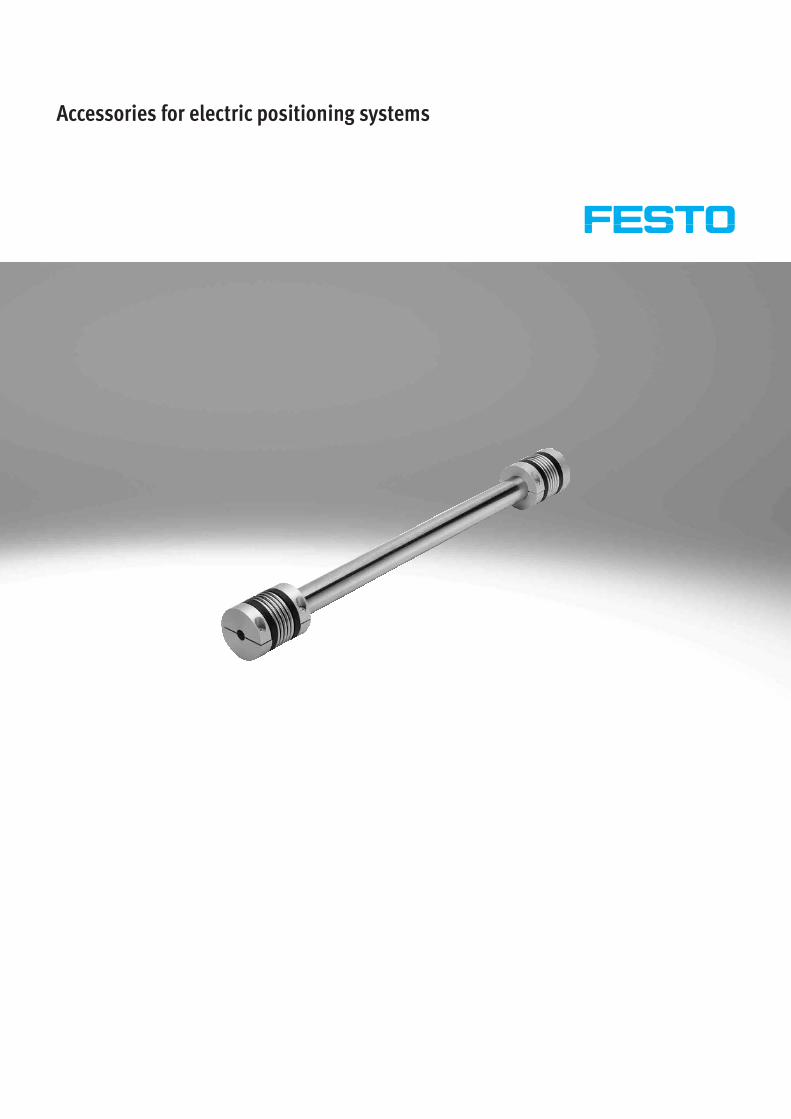
Connecting shafts KSK a Page 13
Electric axes are often combined to form multi-axis systems. When designing gantry systems with a medium centre distance between the axes and heavy loads, it is particularly important that the two basic axes are actuated synchronously. For these systems, two axes with toothed belt drive are generally coupled with a shared motor and synchronised using a connecting shaft.Range of applications:• For synchronising toothed belt axes
EGC and ELGA or cantilever axes ELCC
• For torsion-resistant transmission of the necessary torque
• For slip-free transmission of an identical feed speed
• For compensating tolerances and alignment errors between two axes
Key features
32021/06 – Subject to change d Internet: www.festo.com/catalogue/...
Couplings EAMC
Type codes
001 Series
EAMC Coupling
002 Coupling type
B Bellows coupling
Ring gear coupling
003 Collar diameter [mm]
15 15
16 16
19 19
20 20
30 30
40 40
42 42
56 56
65 65
67 67
004 Length
20 20 mm
22 22 mm
24 24 mm
30 30 mm
32 32 mm
35 35 mm
50 50 mm
58 58 mm
62 62 mm
66 66 mm
90 90 mm
005 Inside diameter 1
3 3 mm
4 4 mm
5 5 mm
6 6 mm
6.35 6.35 mm
8 8 mm
9 9 mm
10 10 mm
11 11 mm
12 12 mm
14 14 mm
15 15 mm
19 19 mm
20 20 mm
22 22 mm
24 24 mm
25 25 mm
XX Closed
006 Inside diameter 2
5 5 mm
6 6 mm
6.35 6.35 mm
8 8 mm
9 9 mm
10 10 mm
11 11 mm
12 12 mm
14 14 mm
15 15 mm
16 16 mm
19 19 mm
20 20 mm
22 22 mm
24 24 mm
25 25 mm
32 32 mm
40 40 mm
4 d Internet: www.festo.com/catalogue/... Subject to change – 2021/06
Couplings EAMC
Data sheet
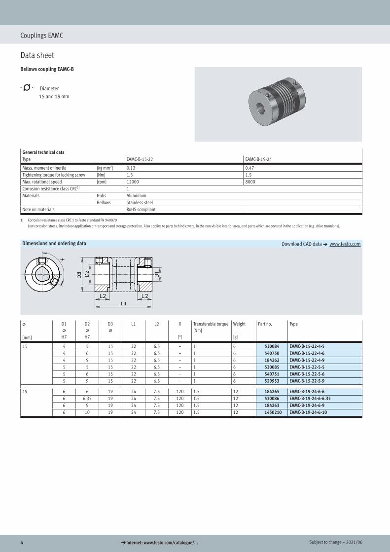
Bellows coupling EAMC-B
-N- Diameter 15 and 19 mm
General technical dataType EAMC-B-15-22 EAMC-B-19-24
Mass. moment of inertia [kg mm2] 0.13 0.47Tightening torque for locking screw [Nm] 1.5 1.5Max. rotational speed [rpm] 12000 8000Corrosion resistance class CRC1) 1Materials Hubs Aluminium
Bellows Stainless steelNote on materials RoHS-compliant
1) Corrosion resistance class CRC 1 to Festo standard FN 940070
Low corrosion stress. Dry indoor application or transport and storage protection. Also applies to parts behind covers, in the non-visible interior area, and parts which are covered in the application (e.g. drive trunnions).
Dimensions and ordering data Download CAD data a www.festo.com
@
[mm]
D1@
H7
D2@
H7
D3@
L1 L2 X
[°]
Transferable torque[Nm]
Weight
[g]
Part no. Type
15 4 5 15 22 6.5 – 1 6 530084 EAMC-B-15-22-4-54 6 15 22 6.5 – 1 6 540750 EAMC-B-15-22-4-64 9 15 22 6.5 – 1 6 184262 EAMC-B-15-22-4-95 5 15 22 6.5 – 1 6 530085 EAMC-B-15-22-5-55 6 15 22 6.5 – 1 6 540751 EAMC-B-15-22-5-65 9 15 22 6.5 – 1 6 529953 EAMC-B-15-22-5-9
19 6 6 19 24 7.5 120 1.5 12 184265 EAMC-B-19-24-6-66 6.35 19 24 7.5 120 1.5 12 530086 EAMC-B-19-24-6-6.356 9 19 24 7.5 120 1.5 12 184263 EAMC-B-19-24-6-96 10 19 24 7.5 120 1.5 12 1450210 EAMC-B-19-24-6-10
Bellows couplings EAMC
Data sheet
Dimensions
Ordering data
52021/06 – Subject to change d Internet: www.festo.com/catalogue/...
Couplings EAMC
Data sheet
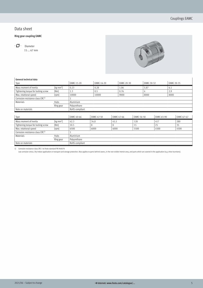
Ring gear coupling EAMC
-N- Diameter 15 ... 67 mm
General technical dataType EAMC-15-20 EAMC-16-20 EAMC-20-30 EAMC-30-32 EAMC-30-35
Mass moment of inertia [kg mm2] 0.23 0.28 1.06 5.87 6.1Tightening torque for locking screw [Nm] 1.3 0.5 0.76 4 2.9Max. rotational speed [rpm] 10000 10000 9000 8000 8000Corrosion resistance class CRC1) 1Materials Hubs Aluminium
Ring gear PolyurethaneNote on materials RoHS-compliant
Type EAMC-40-66 EAMC-42-50 EAMC-42-66 EAMC-56-58 EAMC-65-90 EAMC-67-62
Mass moment of inertia [kg mm2] 42.3 34.8 45.5 128 417 280Tightening torque for locking screw [Nm] 10.5 8 8 15 25 35Max. rotational speed [rpm] 6500 6000 6000 5500 4500 4500Corrosion resistance class CRC1) 1Materials Hubs Aluminium
Ring gear PolyurethaneNote on materials RoHS-compliant
1) Corrosion resistance class CRC 1 to Festo standard FN 940070
Low corrosion stress. Dry indoor application or transport and storage protection. Also applies to parts behind covers, in the non-visible interior area, and parts which are covered in the application (e.g. drive trunnions).
Ring gear couplings EAMC
Data sheet
6 d Internet: www.festo.com/catalogue/... Subject to change – 2021/06
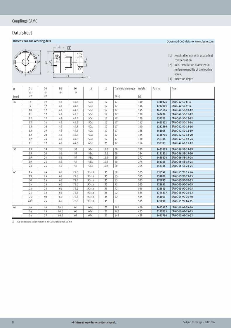
Couplings EAMC
Data sheet
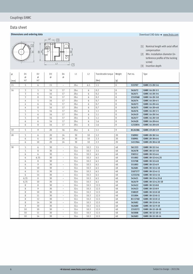
Dimensions and ordering data Download CAD data a www.festo.com
[1] Nominal length with axial offset compensation
[2] Min. installation diameter (in-terference profile of the locking screw)
[3] Insertion depth
@
[mm]
D1@
H7
D2@
H7
D3@
D4@
L1 L2 Transferable torque
[Nm]
Weight
[g]
Part no. Type
15 5 6 15 – 20±1 6.5 1.5 8 533707 EAMC-15-20-5-6
16 3 5 16 17 20±1 6 0.2 8 562672 EAMC-16-20-3-53 6 16 17 20±1 6 0.2 8 562671 EAMC-16-20-3-63 8 16 17 20±1 6 0.2 8 2310368 EAMC-16-20-3-84 5 16 17 20±1 6 0.7 8 562674 EAMC-16-20-4-54 6 16 17 20±1 6 0.7 8 562673 EAMC-16-20-4-64 8 16 17 20±1 6 0.7 8 562675 EAMC-16-20-4-85 5 16 17 20±1 6 1.1 8 562676 EAMC-16-20-5-55 6 16 17 20±1 6 1.1 8 543419 EAMC-16-20-5-65 8 16 17 20±1 6 1.1 8 562677 EAMC-16-20-5-86 6 16 17 20±1 6 1.6 8 543420 EAMC-16-20-6-66 8 16 17 20±1 6 1.6 8 1232854 EAMC-16-20-6-8
19 5 9 20 16 20±1 6 1.1 9 8126386 EAMC-19-20-5-9
20 5 6 20 24 30 10 2.2 20 558902 EAMC-20-30-5-66 6 20 24 30 10 2.3 20 558901 EAMC-20-30-6-66 10 20 24 30 10 2.3 20 1451964 EAMC-20-30-6-10
30 5 6 30 – 32±1 10.3 3.5 48 561333 EAMC-30-32-5-65 8 30 – 32±1 10.3 3.5 48 562678 EAMC-30-32-5-86 6 30 – 32±1 10.3 6.5 48 558312 EAMC-30-32-6-66 6.35 30 – 32±1 10.3 6.5 48 551002 EAMC-30-32-6-6.356 8 30 – 32±1 10.3 6.5 48 533708 EAMC-30-32-6-86 9 30 – 32±1 10.3 6.5 48 551003 EAMC-30-32-6-96 10 30 – 32±1 10.3 6.5 48 562681 EAMC-30-32-6-106 11 30 – 32±1 10.3 6.5 48 3187577 EAMC-30-32-6-116 14 30 – 32±1 10.3 6.5 48 1233256 EAMC-30-32-6-14
6.35 8 30 – 32±1 10.3 6.5 48 543421 EAMC-30-32-6.35-86.35 10 30 – 32±1 10.3 6.5 48 562679 EAMC-30-32-6.35-10
8 8 30 – 32±1 10.3 12.5 48 543422 EAMC-30-32-8-88 9 30 – 32±1 10.3 12.5 48 543423 EAMC-30-32-8-98 10 30 – 32±1 10.3 12.5 48 558029 EAMC-30-32-8-108 11 30 – 32±1 10.3 12.5 48 551004 EAMC-30-32-8-118 12 30 – 32±1 10.3 12.5 48 8115760 EAMC-30-32-8-128 14 30 – 32±1 10.3 12.5 48 562682 EAMC-30-32-8-149 10 30 – 32±1 10.3 12.5 48 562680 EAMC-30-32-9-10
10 10 30 – 32±1 10.3 12.5 48 2310372 EAMC-30-32-10-1010 11 30 – 32±1 10.3 12.5 48 565008 EAMC-30-32-10-1110 14 30 – 32±1 10.3 12.5 48 562683 EAMC-30-32-10-14
Dimensions
Ordering data
72021/06 – Subject to change d Internet: www.festo.com/catalogue/...
Couplings EAMC
Data sheet
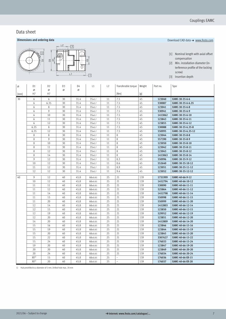
Dimensions and ordering data Download CAD data a www.festo.com
[1] Nominal length with axial offset compensation
[2] Min. installation diameter (in-terference profile of the locking screw)
[3] Insertion depth
@
[mm]
D1@
H7
D2@
H7
D3@
D4@
L1 L2 Transferable torque
[Nm]
Weight
[g]
Part no. Type
30 6 6 30 31.4 35±0.7 11 7.5 45 123040 EAMC-30-35-6-66 6.35 30 31.4 35±0.7 11 7.5 45 530087 EAMC-30-35-6-6.356 8 30 31.4 35±0.7 11 7.5 45 123041 EAMC-30-35-6-86 9 30 31.4 35±0.7 11 7.5 45 530941 EAMC-30-35-6-96 10 30 31.4 35±0.7 11 7.5 45 1453062 EAMC-30-35-6-106 11 30 31.4 35±0.7 11 7.5 45 123843 EAMC-30-35-6-116 12 30 31.4 35±0.7 11 7.5 45 123855 EAMC-30-35-6-12
6.35 8 30 31.4 35±0.7 11 7.5 45 530088 EAMC-30-35-6.35-86.35 12 30 31.4 35±0.7 11 7.5 45 550995 EAMC-30-35-6.35-12
8 8 30 31.4 35±0.7 11 8 45 123044 EAMC-30-35-8-88 9 30 31.4 35±0.7 11 8 45 557390 EAMC-30-35-8-98 10 30 31.4 35±0.7 11 8 45 123050 EAMC-30-35-8-108 11 30 31.4 35±0.7 11 8 45 123042 EAMC-30-35-8-118 12 30 31.4 35±0.7 11 8 45 123043 EAMC-30-35-8-128 14 30 31.4 35±0.7 11 8 45 1453063 EAMC-30-35-8-149 12 30 31.4 35±0.7 11 8.3 45 550996 EAMC-30-35-9-12
10 12 30 31.4 35±0.7 11 8.6 45 552640 EAMC-30-35-10-1211 12 30 31.4 35±0.7 11 8.9 45 123051 EAMC-30-35-11-1212 12 30 31.4 35±0.7 11 9.4 45 123052 EAMC-30-35-12-12
40 9 12 40 45.8 66±0.85 25 21 139 1731999 EAMC-40-66-9-1210 12 40 45.8 66±0.85 25 21 139 1452794 EAMC-40-66-10-1211 11 40 45.8 66±0.85 25 21 139 530090 EAMC-40-66-11-1111 12 40 45.8 66±0.85 25 21 139 525864 EAMC-40-66-11-1211 14 40 45.8 66±0.85 25 21 139 1452798 EAMC-40-66-11-1411 15 40 45.8 66±0.85 25 21 139 550998 EAMC-40-66-11-1511 20 40 45.8 66±0.85 25 21 139 550999 EAMC-40-66-11-2012 14 40 45.8 66±0.85 25 21 139 1452803 EAMC-40-66-12-1412 15 40 45.8 66±0.85 25 21 139 123850 EAMC-40-66-12-1512 19 40 45.8 66±0.85 25 21 139 529952 EAMC-40-66-12-1912 20 40 45.8 66±0.85 25 21 139 123851 EAMC-40-66-12-2014 20 40 45.8 66±0.85 25 21 139 1452809 EAMC-40-66-14-2015 16 40 45.8 66±0.85 25 21 139 123846 EAMC-40-66-15-1615 19 40 45.8 66±0.85 25 21 139 123844 EAMC-40-66-15-1915 20 40 45.8 66±0.85 25 21 139 123845 EAMC-40-66-15-2015 22 40 45.8 66±0.85 25 21 139 3307627 EAMC-40-66-15-2215 24 40 45.8 66±0.85 25 21 139 176033 EAMC-40-66-15-2419 20 40 45.8 66±0.85 25 21 139 123847 EAMC-40-66-19-2020 20 40 45.8 66±0.85 25 21 139 123849 EAMC-40-66-20-2020 24 40 45.8 66±0.85 25 21 139 176034 EAMC-40-66-20-24
XX1) 15 40 45.8 66±0.85 25 – 139 176036 EAMC-40-66-XX-15XX1) 20 40 45.8 66±0.85 25 – 139 176037 EAMC-40-66-XX-20
1) Hub predrilled to a diameter of 5 mm. Drilled hole max. 20 mm
8 d Internet: www.festo.com/catalogue/... Subject to change – 2021/06
Couplings EAMC
Data sheet
Dimensions and ordering data Download CAD data a www.festo.com
[1] Nominal length with axial offset compensation
[2] Min. installation diameter (in-terference profile of the locking screw)
[3] Insertion depth
@
[mm]
D1@
H7
D2@
H7
D3@
D4@
L1 L2 Transferable torque
[Nm]
Weight
[g]
Part no. Type
42 8 19 42 44.5 50±2 17 17 140 2310376 EAMC-42-50-8-199 12 42 44.5 50±2 17 17 146 1732001 EAMC-42-50-9-12
10 12 42 44.5 50±2 17 17 145 1455666 EAMC-42-50-10-1211 12 42 44.5 50±2 17 17 138 543424 EAMC-42-50-11-1212 12 42 44.5 50±2 17 17 138 533709 EAMC-42-50-12-1212 14 42 44.5 50±2 17 17 142 1455671 EAMC-42-50-12-1412 16 42 44.5 50±2 17 17 140 1232880 EAMC-42-50-12-1612 19 42 44.5 50±2 17 17 138 551005 EAMC-42-50-12-1912 20 42 44.5 50±2 17 17 135 2138701 EAMC-42-50-12-2012 24 42 44.5 50±2 17 17 130 558314 EAMC-42-50-12-2411 12 42 44.5 66±2 25 17 166 558313 EAMC-42-66-11-12
56 19 19 56 57 58±2 19.9 60 285 1485673 EAMC-56-58-19-1919 20 56 57 58±2 19.9 60 284 3181801 EAMC-56-58-19-2019 24 56 57 58±2 19.9 60 277 1485674 EAMC-56-58-19-2419 25 56 57 58±2 19.9 60 275 558315 EAMC-56-58-19-2524 25 56 57 58±2 19.9 60 265 558316 EAMC-56-58-24-25
65 15 24 65 72.6 90±1.1 35 80 535 530940 EAMC-65-90-15-2419 25 65 72.6 90±1.1 35 85 535 551000 EAMC-65-90-19-2520 25 65 72.6 90±1.1 35 85 535 176035 EAMC-65-90-20-2524 25 65 72.6 90±1.1 35 92 535 123852 EAMC-65-90-24-2525 25 65 72.6 90±1.1 35 92 535 123853 EAMC-65-90-25-2525 32 65 72.6 90±1.1 35 92 535 1745817 EAMC-65-90-25-3225 40 65 72.6 90±1.1 35 62 535 551001 EAMC-65-90-25-40
XX2) 25 65 72.6 90±1.1 35 – 535 176038 EAMC-65-90-XX-25
67 24 24 66.5 68 62±2 21 143 436 1451407 EAMC-67-62-24-2424 25 66.5 68 62±2 21 143 435 3187895 EAMC-67-62-24-2524 32 66.5 68 62±2 21 143 428 1485796 EAMC-67-62-24-32
2) Hub predrilled to a diameter of 9.5 mm. Drilled hole max. 38 mm
92021/06 – Subject to change d Internet: www.festo.com/catalogue/...
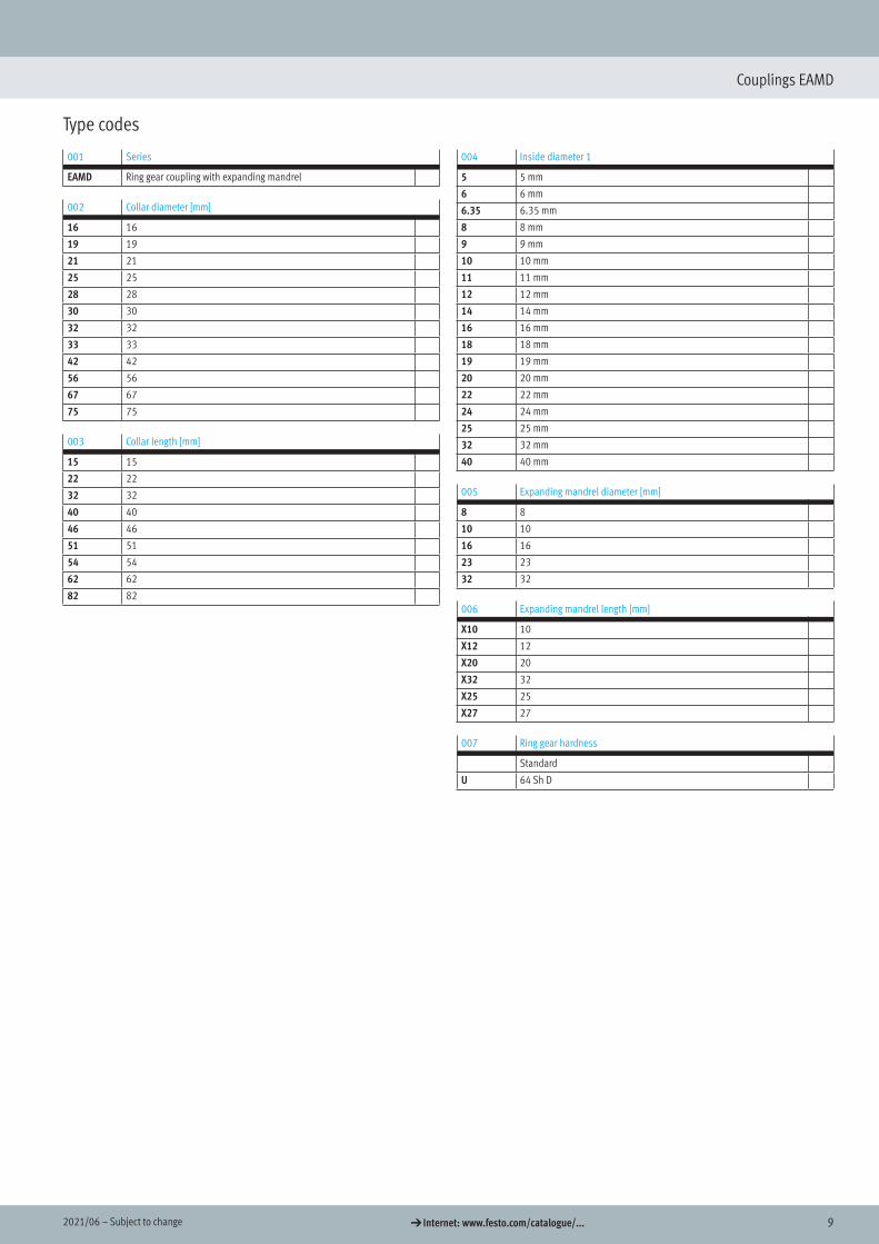
Couplings EAMD
Type codes
001 Series
EAMD Ring gear coupling with expanding mandrel
002 Collar diameter [mm]
16 16
19 19
21 21
25 25
28 28
30 30
32 32
33 33
42 42
56 56
67 67
75 75
003 Collar length [mm]
15 15
22 22
32 32
40 40
46 46
51 51
54 54
62 62
82 82
004 Inside diameter 1
5 5 mm
6 6 mm
6.35 6.35 mm
8 8 mm
9 9 mm
10 10 mm
11 11 mm
12 12 mm
14 14 mm
16 16 mm
18 18 mm
19 19 mm
20 20 mm
22 22 mm
24 24 mm
25 25 mm
32 32 mm
40 40 mm
005 Expanding mandrel diameter [mm]
8 8
10 10
16 16
23 23
32 32
006 Expanding mandrel length [mm]
X10 10
X12 12
X20 20
X32 32
X25 25
X27 27
007 Ring gear hardness
Standard
U 64 Sh D
10 d Internet: www.festo.com/catalogue/... Subject to change – 2021/06
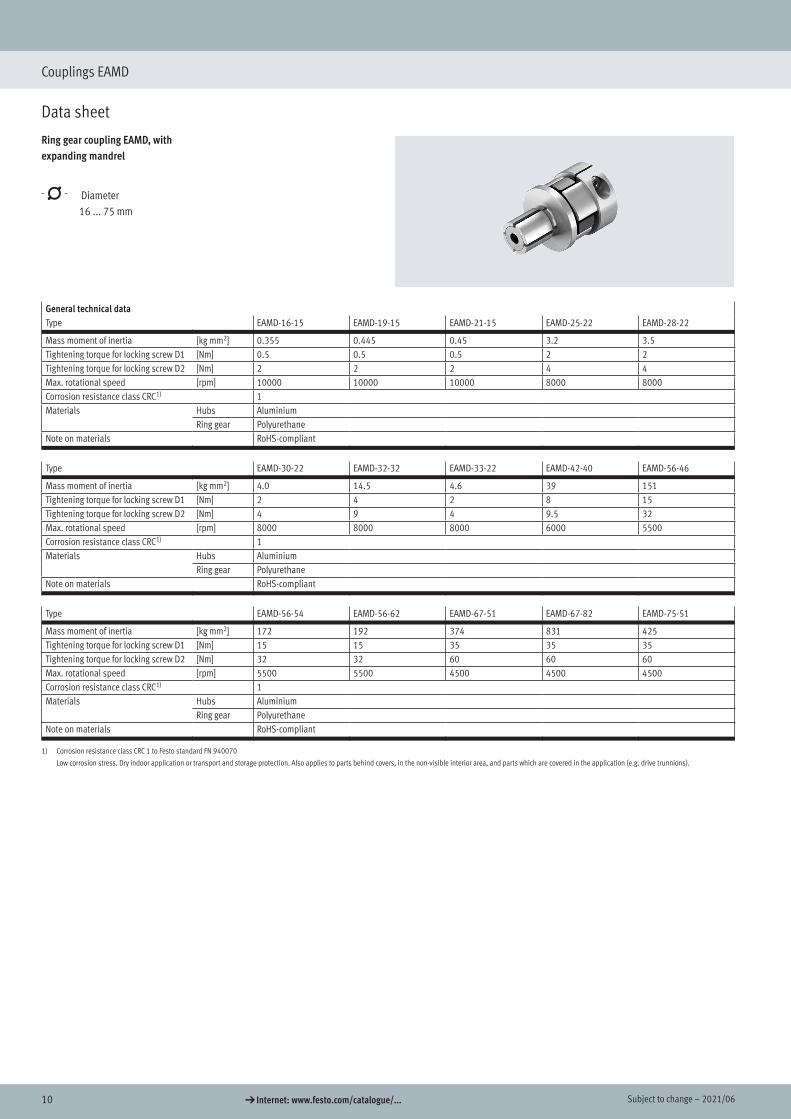
Couplings EAMD
Data sheet
Ring gear coupling EAMD, with expanding mandrel
-N- Diameter 16 ... 75 mm
General technical dataType EAMD-16-15 EAMD-19-15 EAMD-21-15 EAMD-25-22 EAMD-28-22
Mass moment of inertia [kg mm2] 0.355 0.445 0.45 3.2 3.5Tightening torque for locking screw D1 [Nm] 0.5 0.5 0.5 2 2Tightening torque for locking screw D2 [Nm] 2 2 2 4 4Max. rotational speed [rpm] 10000 10000 10000 8000 8000Corrosion resistance class CRC1) 1Materials Hubs Aluminium
Ring gear PolyurethaneNote on materials RoHS-compliant
Type EAMD-30-22 EAMD-32-32 EAMD-33-22 EAMD-42-40 EAMD-56-46
Mass moment of inertia [kg mm2] 4.0 14.5 4.6 39 151Tightening torque for locking screw D1 [Nm] 2 4 2 8 15Tightening torque for locking screw D2 [Nm] 4 9 4 9.5 32Max. rotational speed [rpm] 8000 8000 8000 6000 5500Corrosion resistance class CRC1) 1Materials Hubs Aluminium
Ring gear PolyurethaneNote on materials RoHS-compliant
Type EAMD-56-54 EAMD-56-62 EAMD-67-51 EAMD-67-82 EAMD-75-51
Mass moment of inertia [kg mm2] 172 192 374 831 425Tightening torque for locking screw D1 [Nm] 15 15 35 35 35Tightening torque for locking screw D2 [Nm] 32 32 60 60 60Max. rotational speed [rpm] 5500 5500 4500 4500 4500Corrosion resistance class CRC1) 1Materials Hubs Aluminium
Ring gear PolyurethaneNote on materials RoHS-compliant
1) Corrosion resistance class CRC 1 to Festo standard FN 940070
Low corrosion stress. Dry indoor application or transport and storage protection. Also applies to parts behind covers, in the non-visible interior area, and parts which are covered in the application (e.g. drive trunnions).
Ring gear couplings EAMD
Data sheet
112021/06 – Subject to change d Internet: www.festo.com/catalogue/...
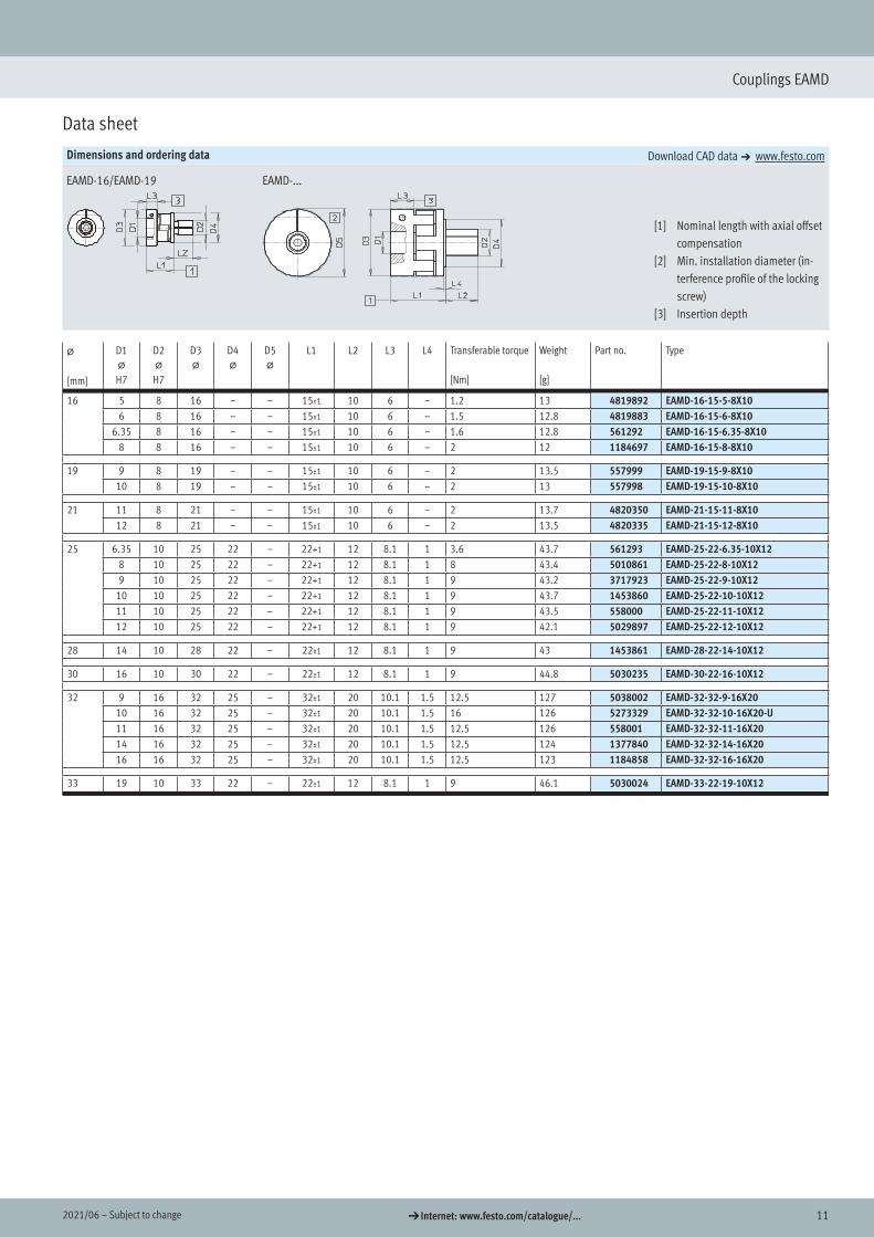
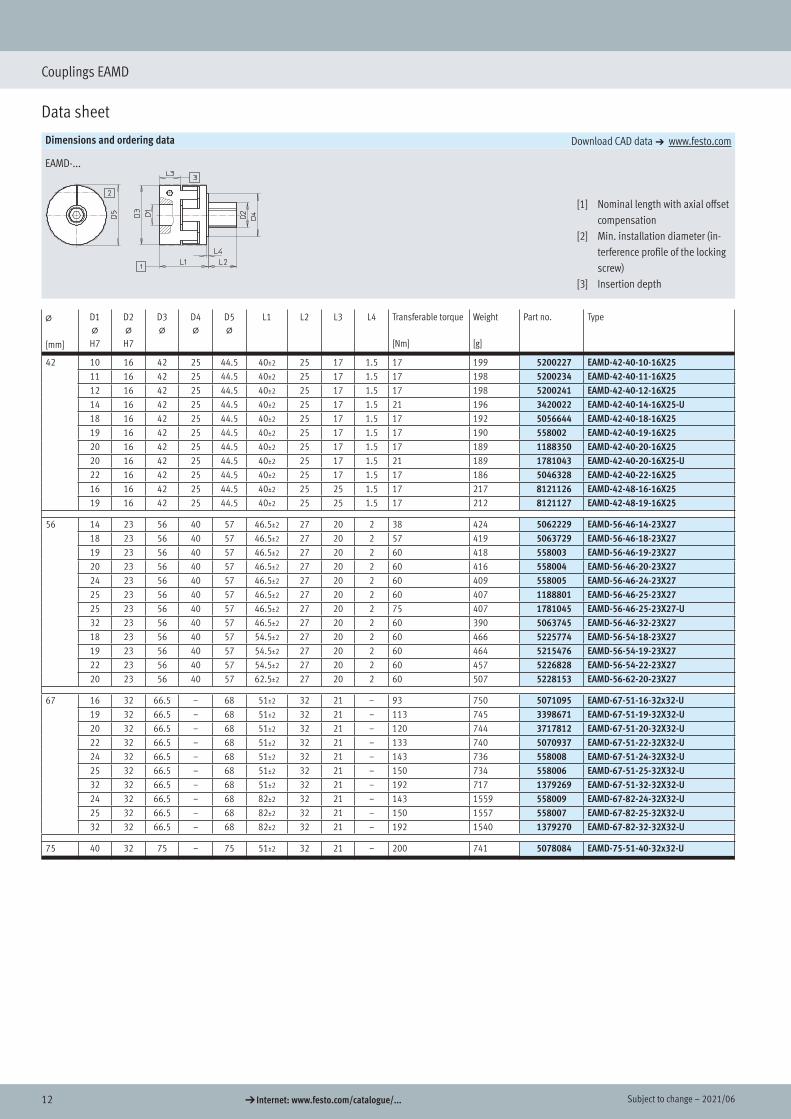
Couplings EAMD
Data sheet
Dimensions and ordering data Download CAD data a www.festo.com
EAMD-16/EAMD-19 EAMD-...
[1] Nominal length with axial offset compensation
[2] Min. installation diameter (in-terference profile of the locking screw)
[3] Insertion depth
@
[mm]
D1@
H7
D2@
H7
D3@
D4@
D5@
L1 L2 L3 L4 Transferable torque
[Nm]
Weight
[g]
Part no. Type
16 5 8 16 – – 15±1 10 6 – 1.2 13 4819892 EAMD-16-15-5-8X10⁶ 8 16 – – 15±1 10 6 – 1.5 12.8 4819883 EAMD-16-15-6-8X10
6.35 8 16 – – 15±1 10 6 – 1.6 12.8 561292 EAMD-16-15-6.35-8X10⁸ 8 16 – – 15±1 10 6 – 2 12 1184697 EAMD-16-15-8-8X10
19 9 8 19 – – 15±1 10 6 – 2 13.5 557999 EAMD-19-15-9-8X10¹⁰ 8 19 – – 15±1 10 6 – 2 13 557998 EAMD-19-15-10-8X10
21 11 8 21 – – 15±1 10 6 – 2 13.7 4820350 EAMD-21-15-11-8X10¹² 8 21 – – 15±1 10 6 – 2 13.5 4820335 EAMD-21-15-12-8X10
25 6.35 10 25 22 – 22+1 12 8.1 1 3.6 43.7 561293 EAMD-25-22-6.35-10X128 10 25 22 – 22+1 12 8.1 1 8 43.4 5010861 EAMD-25-22-8-10X129 10 25 22 – 22+1 12 8.1 1 9 43.2 3717923 EAMD-25-22-9-10X12
10 10 25 22 – 22+1 12 8.1 1 9 43.7 1453860 EAMD-25-22-10-10X1211 10 25 22 – 22+1 12 8.1 1 9 43.5 558000 EAMD-25-22-11-10X1212 10 25 22 – 22+1 12 8.1 1 9 42.1 5029897 EAMD-25-22-12-10X12
28 14 10 28 22 – 22±1 12 8.1 1 9 43 1453861 EAMD-28-22-14-10X12
30 16 10 30 22 – 22±1 12 8.1 1 9 44.8 5030235 EAMD-30-22-16-10X12
32 9 16 32 25 – 32±1 20 10.1 1.5 12.5 127 5038002 EAMD-32-32-9-16X2010 16 32 25 – 32±1 20 10.1 1.5 16 126 5273329 EAMD-32-32-10-16X20-U11 16 32 25 – 32±1 20 10.1 1.5 12.5 126 558001 EAMD-32-32-11-16X2014 16 32 25 – 32±1 20 10.1 1.5 12.5 124 1377840 EAMD-32-32-14-16X2016 16 32 25 – 32±1 20 10.1 1.5 12.5 123 1184858 EAMD-32-32-16-16X20
33 19 10 33 22 – 22±1 12 8.1 1 9 46.1 5030024 EAMD-33-22-19-10X12
Dimensions
Ordering data
12 d Internet: www.festo.com/catalogue/... Subject to change – 2021/06
Couplings EAMD
Data sheet
Dimensions and ordering data Download CAD data a www.festo.com
EAMD-...
[1] Nominal length with axial offset compensation
[2] Min. installation diameter (in-terference profile of the locking screw)
[3] Insertion depth
@
[mm]
D1@
H7
D2@
H7
D3@
D4@
D5@
L1 L2 L3 L4 Transferable torque
[Nm]
Weight
[g]
Part no. Type
42 10 16 42 25 44.5 40±2 25 17 1.5 17 199 5200227 EAMD-42-40-10-16X2511 16 42 25 44.5 40±2 25 17 1.5 17 198 5200234 EAMD-42-40-11-16X2512 16 42 25 44.5 40±2 25 17 1.5 17 198 5200241 EAMD-42-40-12-16X2514 16 42 25 44.5 40±2 25 17 1.5 21 196 3420022 EAMD-42-40-14-16X25-U18 16 42 25 44.5 40±2 25 17 1.5 17 192 5056644 EAMD-42-40-18-16X2519 16 42 25 44.5 40±2 25 17 1.5 17 190 558002 EAMD-42-40-19-16X2520 16 42 25 44.5 40±2 25 17 1.5 17 189 1188350 EAMD-42-40-20-16X2520 16 42 25 44.5 40±2 25 17 1.5 21 189 1781043 EAMD-42-40-20-16X25-U22 16 42 25 44.5 40±2 25 17 1.5 17 186 5046328 EAMD-42-40-22-16X2516 16 42 25 44.5 40±2 25 25 1.5 17 217 8121126 EAMD-42-48-16-16X2519 16 42 25 44.5 40±2 25 25 1.5 17 212 8121127 EAMD-42-48-19-16X25
56 14 23 56 40 57 46.5±2 27 20 2 38 424 5062229 EAMD-56-46-14-23X2718 23 56 40 57 46.5±2 27 20 2 57 419 5063729 EAMD-56-46-18-23X2719 23 56 40 57 46.5±2 27 20 2 60 418 558003 EAMD-56-46-19-23X2720 23 56 40 57 46.5±2 27 20 2 60 416 558004 EAMD-56-46-20-23X2724 23 56 40 57 46.5±2 27 20 2 60 409 558005 EAMD-56-46-24-23X2725 23 56 40 57 46.5±2 27 20 2 60 407 1188801 EAMD-56-46-25-23X2725 23 56 40 57 46.5±2 27 20 2 75 407 1781045 EAMD-56-46-25-23X27-U32 23 56 40 57 46.5±2 27 20 2 60 390 5063745 EAMD-56-46-32-23X2718 23 56 40 57 54.5±2 27 20 2 60 466 5225774 EAMD-56-54-18-23X2719 23 56 40 57 54.5±2 27 20 2 60 464 5215476 EAMD-56-54-19-23X2722 23 56 40 57 54.5±2 27 20 2 60 457 5226828 EAMD-56-54-22-23X2720 23 56 40 57 62.5±2 27 20 2 60 507 5228153 EAMD-56-62-20-23X27
67 16 32 66.5 – 68 51±2 32 21 – 93 750 5071095 EAMD-67-51-16-32x32-U19 32 66.5 – 68 51±2 32 21 – 113 745 3398671 EAMD-67-51-19-32X32-U20 32 66.5 – 68 51±2 32 21 – 120 744 3717812 EAMD-67-51-20-32X32-U22 32 66.5 – 68 51±2 32 21 – 133 740 5070937 EAMD-67-51-22-32X32-U24 32 66.5 – 68 51±2 32 21 – 143 736 558008 EAMD-67-51-24-32X32-U25 32 66.5 – 68 51±2 32 21 – 150 734 558006 EAMD-67-51-25-32X32-U32 32 66.5 – 68 51±2 32 21 – 192 717 1379269 EAMD-67-51-32-32X32-U24 32 66.5 – 68 82±2 32 21 – 143 1559 558009 EAMD-67-82-24-32X32-U25 32 66.5 – 68 82±2 32 21 – 150 1557 558007 EAMD-67-82-25-32X32-U32 32 66.5 – 68 82±2 32 21 – 192 1540 1379270 EAMD-67-82-32-32X32-U
75 40 32 75 – 75 51±2 32 21 – 200 741 5078084 EAMD-75-51-40-32x32-U
132021/06 – Subject to change d Internet: www.festo.com/catalogue/...
Connecting shafts KSK
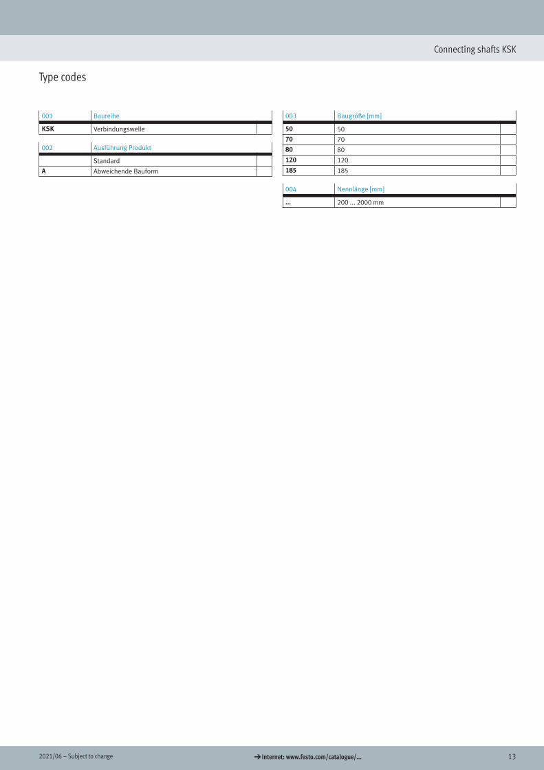
Type codes
001 Baureihe
KSK Verbindungswelle
002 Ausführung Produkt
Standard
A Abweichende Bauform
003 Baugröße [mm]
50 50
70 70
80 80
120 120
185 185
004 Nennlänge [mm]
... 200 ... 2000 mm
Connecting shafts
14 d Internet: www.festo.com/catalogue/... Subject to change – 2021/06
Connecting shafts KSK
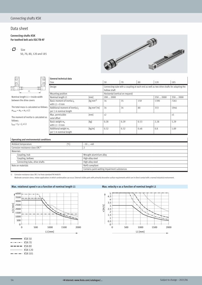
Data sheet
Connecting shafts KSKFor toothed belt axis EGC-TB-KF
-N- Size 50, 70, 80, 120 and 185
General technical dataSize 50 70 80 120 185
Nominal length L1 = Inside width between the drive covers
The total mass is calculated as follows:mtotal = m0 + mL x L1
The moment of inertia is calculated as follows:Jtotal = J0 + JL x L1
Design Connecting tube with a coupling at each end as well as two drive shafts for adapting the hollow shaft
Mounting position Horizontal (vertical on request)Nominal length L1 [mm] 200 ... 2000 250 ... 2000 350 ... 2000Basic moment of inertia J0
with L1 = 0 mm[kg mm2] 34 35 159 1390 7261
Additional moment of inertia JL
per 1 m nominal length[kg mm2/m] 34 34 80 333 1946
Max. permissible axial offset
[mm] ±2 ±5
Basic weight m0
with L1 = 0 mm[kg] 0.28 0.29 0.53 2.28 5.29
Additional weight mL
per 1 m nominal length[kg/m] 0.32 0.32 0.48 0.8 1.89
Operating and environmental conditions
Ambient temperature [°C] –10 ... +60Corrosion resistance class CRC1) 2Materials
Coupling, hub Wrought aluminium alloyCoupling, bellows High-alloy steelConnecting tube, drive shafts High-alloy steel
Note on materials RoHS-compliantContains paint-wetting impairment substances
1) Corrosion resistance class CRC 2 to Festo standard FN 940070
Moderate corrosion stress. Indoor applications in which condensation can occur. External visible parts with primarily decorative surface requirements which are in direct contact with a normal industrial environment.
Max. rotational speed n as a function of nominal length L1 Max. velocity v as a function of nominal length L1KSK-...
L1 [mm]
n[1
/min
]
0 500 1000 1500 20000
500
1000
1500
2000
2500
3000
3500
4000
KSK-...
L1 [mm]
v[m
/s]
0 500 1000 1500 20000
0.5
1
1.5
22.5
3
3.5
4
4.55
KSK-50KSK-70KSK-80KSK-120KSK-185
For toothed belt axis EGC-TB-KF
Data sheet
L1
152021/06 – Subject to change d Internet: www.festo.com/catalogue/...
Connecting shafts KSK
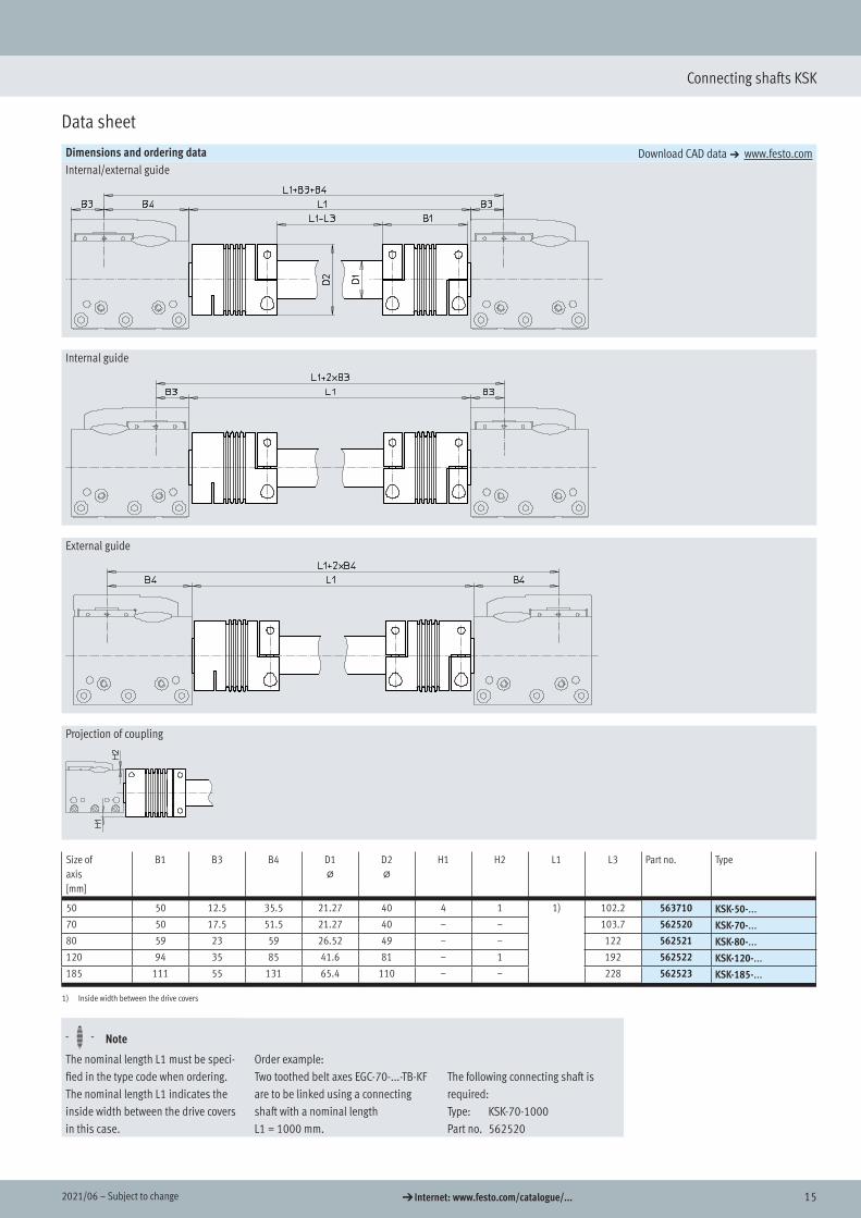
Data sheet
Dimensions and ordering data Download CAD data a www.festo.comInternal/external guide
Internal guide
External guide
Projection of coupling
Size of axis[mm]
B1 B3 B4 D1@
D2@
H1 H2 L1 L3 Part no. Type
50 50 12.5 35.5 21.27 40 4 1 1) 102.2 563710 KSK-50-...70 50 17.5 51.5 21.27 40 – – 103.7 562520 KSK-70-...80 59 23 59 26.52 49 – – 122 562521 KSK-80-...120 94 35 85 41.6 81 – 1 192 562522 KSK-120-...185 111 55 131 65.4 110 – – 228 562523 KSK-185-...
1) Inside width between the drive covers
H- - Note
The nominal length L1 must be speci-fied in the type code when ordering. The nominal length L1 indicates the inside width between the drive covers in this case.
Order example:Two toothed belt axes EGC-70-...-TB-KF are to be linked using a connecting shaft with a nominal length L1 = 1000 mm.
The following connecting shaft is required:Type: KSK-70-1000Part no. 562520
Dimensions
Ordering data
16 d Internet: www.festo.com/catalogue/... Subject to change – 2021/06
Connecting shafts KSK
Data sheet
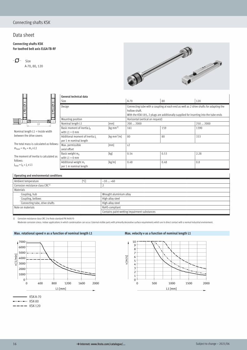
Connecting shafts KSKFor toothed belt axis ELGA-TB-RF
-N- Size A-70, 80, 120
General technical dataSize A-70 80 120
Nominal length L1 = Inside width between the drive covers
The total mass is calculated as follows:mtotal = m0 + mL x L1
The moment of inertia is calculated as follows:Jtotal = J0 + JL x L1
Design Connecting tube with a coupling at each end as well as 2 drive shafts for adapting the hollow shaft.With the KSK-185, 2 plugs are additionally supplied for inserting into the tube ends
Mounting position Horizontal (vertical on request)Nominal length L1 [mm] 200 ... 2000 250 ... 2000Basic moment of inertia J0
with L1 = 0 mm[kg mm2] 161 159 1390
Additional moment of inertia JL
per 1 m nominal length[kg mm2/m] 80 80 333
Max. permissible axial offset
[mm] ±2
Basic weight m0
with L1 = 0 mm[kg] 0.54 0.53 2.28
Additional weight mL
per 1 m nominal length[kg/m] 0.48 0.48 0.8
Operating and environmental conditions
Ambient temperature [°C] –10 ... +60Corrosion resistance class CRC1) 2Materials
Coupling, hub Wrought aluminium alloyCoupling, bellows High-alloy steelConnecting tube, drive shafts High-alloy steel
Note on materials RoHS-compliantContains paint-wetting impairment substances
1) Corrosion resistance class CRC 2 to Festo standard FN 940070
Moderate corrosion stress. Indoor applications in which condensation can occur. External visible parts with primarily decorative surface requirements which are in direct contact with a normal industrial environment.
Max. rotational speed n as a function of nominal length L1 Max. velocity v as a function of nominal length L1KSK-...
L1 [mm]
n[1
/min
]
0 400 800 1200 1600 20000
1000
2000
3000
4000
5000
6000
7000
KSK-...
L1 [mm]
v[m
/s]
0 500 1000 1500 20000
1
2
3
45
6
7
8
910
KSK-A-70KSK-80KSK-120
For toothed belt axis ELGA-TB-RF
Data sheet
L1
172021/06 – Subject to change d Internet: www.festo.com/catalogue/...
Connecting shafts KSK
Data sheet
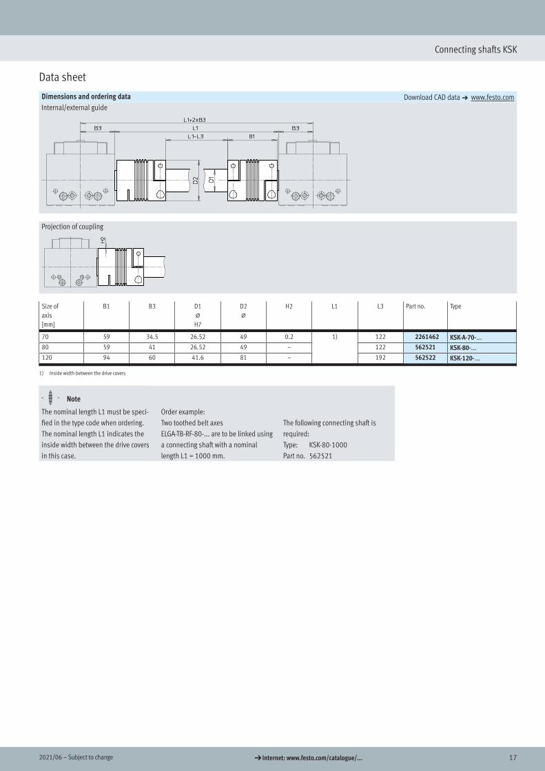
Dimensions and ordering data Download CAD data a www.festo.comInternal/external guide
Projection of coupling
Size of axis[mm]
B1 B3 D1@
H7
D2@
H2 L1 L3 Part no. Type
70 59 34.5 26.52 49 0.2 1) 122 2261462 KSK-A-70-...80 59 41 26.52 49 – 122 562521 KSK-80-...120 94 60 41.6 81 – 192 562522 KSK-120-...
1) Inside width between the drive covers
H- - Note
The nominal length L1 must be speci-fied in the type code when ordering. The nominal length L1 indicates the inside width between the drive covers in this case.
Order example:Two toothed belt axes ELGA-TB-RF-80-... are to be linked using a connecting shaft with a nominal length L1 = 1000 mm.
The following connecting shaft is required:Type: KSK-80-1000Part no. 562521
Dimensions
Ordering data

18 d Internet: www.festo.com/catalogue/... Subject to change – 2021/06
Connecting shafts KSK
Data sheet
Connecting shafts KSKFor toothed belt axis ELGA-TB-KF
-N- Size A-70, 80, 120, 185
The connecting shaft KSK-185 is used in combination with the toothed belt axis ELGA-TB-KF-150.
General technical dataSize A-70 80 120 185
Nominal length L1 = Inside width between the drive covers
The total mass is calculated as follows:mtotal = m0 + mL x L1
The moment of inertia is calculated as follows:Jtotal = J0 + JL x L1
Design Connecting tube with a coupling at each end as well as two drive shafts for adapting the hollow shaft.With the KSK-185, 2 plugs are additionally supplied for inserting into the tube ends
Mounting position Horizontal (vertical on request)Nominal length L1 [mm] 200 ... 2000 250 ... 2000 350 ... 2000Basic moment of inertia J0
with L1 = 0 mm[kg mm2] 161 159 1390 7261
Additional moment of inertia JL
per 1 m nominal length[kg mm2/m] 80 80 333 1946
Max. permissible axial offset
[mm] ±2 ±5
Basic weight m0
with L1 = 0 mm[kg] 0.54 0.53 2.28 5.29
Additional weight mL
per 1 m nominal length[kg/m] 0.48 0.48 0.8 1.89
Operating and environmental conditions
Ambient temperature [°C] –10 ... +60Corrosion resistance class CRC1) 2Materials
Coupling, hub Wrought aluminium alloyCoupling, bellows High-alloy steelConnecting tube, drive shafts High-alloy steel
Note on materials RoHS-compliantContains paint-wetting impairment substances
1) Corrosion resistance class CRC 2 to Festo standard FN 940070
Moderate corrosion stress. Indoor applications in which condensation can occur. External visible parts with primarily decorative surface requirements which are in direct contact with a normal industrial environment.
Max. rotational speed n as a function of nominal length L1 Max. velocity v as a function of nominal length L1
KSK-A-70KSK-80
KSK-120KSK-185
For toothed belt axis ELGA-TB-KF
Data sheet
L1
192021/06 – Subject to change d Internet: www.festo.com/catalogue/...
Connecting shafts KSK
Data sheet
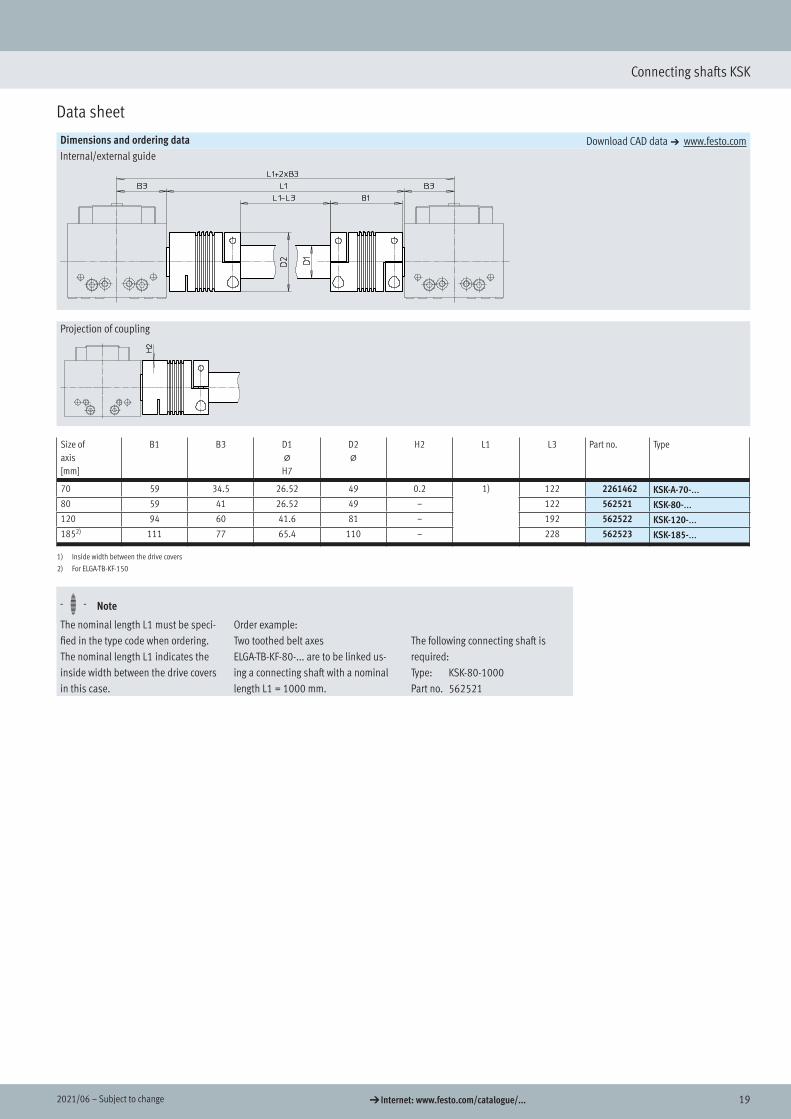
Dimensions and ordering data Download CAD data a www.festo.comInternal/external guide
Projection of coupling
Size of axis[mm]
B1 B3 D1@
H7
D2@
H2 L1 L3 Part no. Type
70 59 34.5 26.52 49 0.2 1) 122 2261462 KSK-A-70-...80 59 41 26.52 49 – 122 562521 KSK-80-...120 94 60 41.6 81 – 192 562522 KSK-120-...1852) 111 77 65.4 110 – 228 562523 KSK-185-...
1) Inside width between the drive covers
2) For ELGA-TB-KF-150
H- - Note
The nominal length L1 must be speci-fied in the type code when ordering. The nominal length L1 indicates the inside width between the drive covers in this case.
Order example:Two toothed belt axes ELGA-TB-KF-80-... are to be linked us-ing a connecting shaft with a nominal length L1 = 1000 mm.
The following connecting shaft is required:Type: KSK-80-1000Part no. 562521
Dimensions
Ordering data
20 d Internet: www.festo.com/catalogue/... Subject to change – 2021/06
Connecting shafts KSK
Data sheet
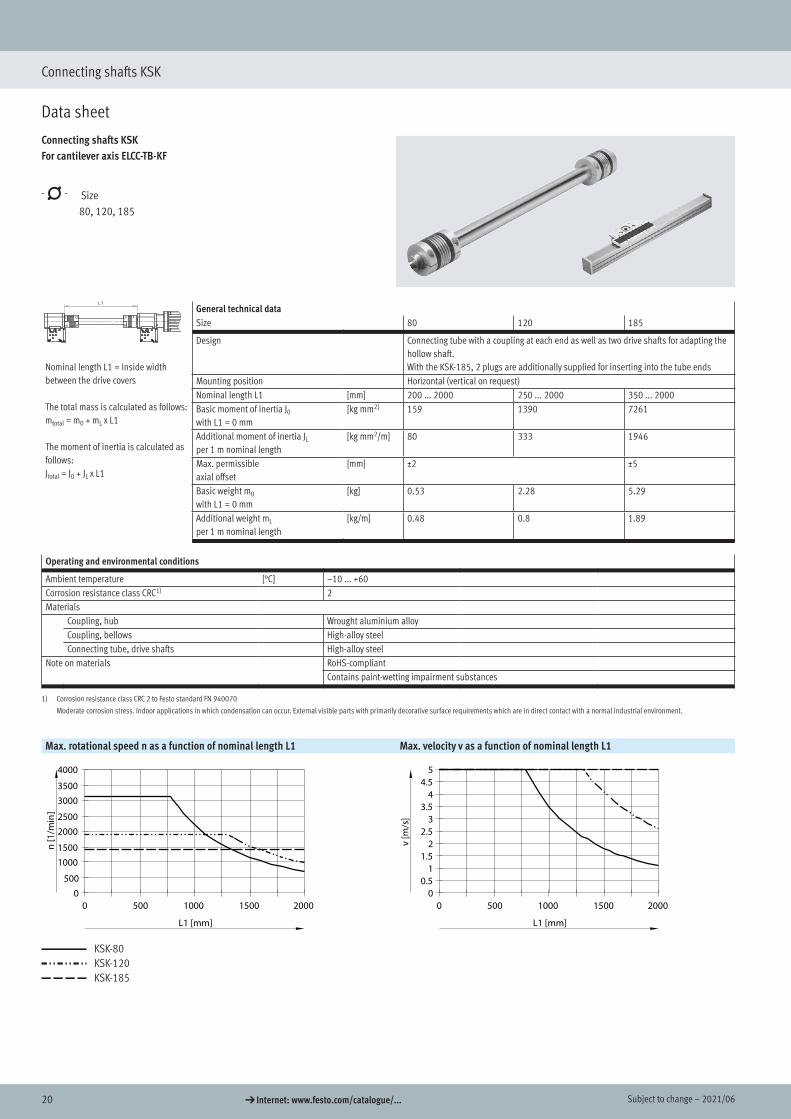
Connecting shafts KSKFor cantilever axis ELCC-TB-KF
-N- Size 80, 120, 185
General technical dataSize 80 120 185
Nominal length L1 = Inside width between the drive covers
The total mass is calculated as follows:mtotal = m0 + mL x L1
The moment of inertia is calculated as follows:Jtotal = J0 + JL x L1
Design Connecting tube with a coupling at each end as well as two drive shafts for adapting the hollow shaft.With the KSK-185, 2 plugs are additionally supplied for inserting into the tube ends
Mounting position Horizontal (vertical on request)Nominal length L1 [mm] 200 ... 2000 250 ... 2000 350 ... 2000Basic moment of inertia J0
with L1 = 0 mm[kg mm2] 159 1390 7261
Additional moment of inertia JL
per 1 m nominal length[kg mm2/m] 80 333 1946
Max. permissible axial offset
[mm] ±2 ±5
Basic weight m0
with L1 = 0 mm[kg] 0.53 2.28 5.29
Additional weight mL
per 1 m nominal length[kg/m] 0.48 0.8 1.89
Operating and environmental conditions
Ambient temperature [°C] –10 ... +60Corrosion resistance class CRC1) 2Materials
Coupling, hub Wrought aluminium alloyCoupling, bellows High-alloy steelConnecting tube, drive shafts High-alloy steel
Note on materials RoHS-compliantContains paint-wetting impairment substances
1) Corrosion resistance class CRC 2 to Festo standard FN 940070
Moderate corrosion stress. Indoor applications in which condensation can occur. External visible parts with primarily decorative surface requirements which are in direct contact with a normal industrial environment.
Max. rotational speed n as a function of nominal length L1 Max. velocity v as a function of nominal length L1KSK-...
L1 [mm]
n [1
/min
]
0 500 1000 1500 20000
500
10001500
20002500
30003500
4000
KSK-...
L1 [mm]
v [m
/s]
0 500 1000 1500 20000
0.51
1.52
2.53
3.54
4.55
KSK-80KSK-120KSK-185
For cantilever axis ELCC-TB-KF
Data sheet
212021/06 – Subject to change d Internet: www.festo.com/catalogue/...
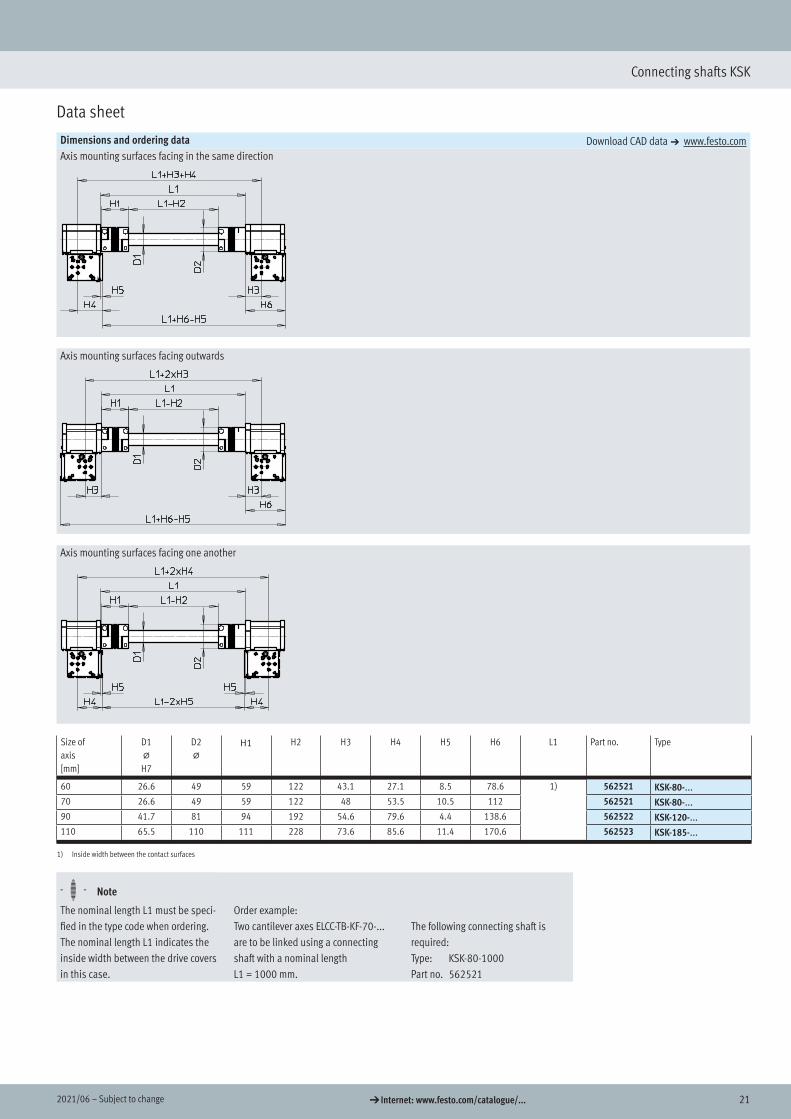
Connecting shafts KSK
Data sheet
Dimensions and ordering data Download CAD data a www.festo.comAxis mounting surfaces facing in the same direction
Axis mounting surfaces facing outwards
Axis mounting surfaces facing one another
Size of axis[mm]
D1@
H7
D2@
H1 H2 H3 H4 H5 H6 L1 Part no. Type
60 26.6 49 59 122 43.1 27.1 8.5 78.6 1) 562521 KSK-80-...70 26.6 49 59 122 48 53.5 10.5 112 562521 KSK-80-...90 41.7 81 94 192 54.6 79.6 4.4 138.6 562522 KSK-120-...110 65.5 110 111 228 73.6 85.6 11.4 170.6 562523 KSK-185-...
1) Inside width between the contact surfaces
H- - Note
The nominal length L1 must be speci-fied in the type code when ordering. The nominal length L1 indicates the inside width between the drive covers in this case.
Order example:Two cantilever axes ELCC-TB-KF-70-... are to be linked using a connecting shaft with a nominal length L1 = 1000 mm.
The following connecting shaft is required:Type: KSK-80-1000Part no. 562521
Dimensions
Ordering data
Festo - Your Partner in Automation
www.festo.com
Connect with us
www.festo.com/socialmedia
1 Festo Inc. 2 Festo Pneumatic 3 Festo Corporation 4 Regional Service Center
5300 Explorer DriveMississauga, ON L4W 5G4Canada
Av. Ceylán 3,Col. Tequesquináhuac54020 Tlalnepantla, Estado de México
1377 Motor ParkwaySuite 310Islandia, NY 11749
7777 Columbia RoadMason, OH 45040
Festo Customer Interaction CenterTel: 1 877 463 3786Fax: 1 877 393 3786Email: [email protected]
Multinational Contact Center01 800 337 8669
Festo Customer Interaction Center1 800 993 37861 800 963 3786
Subj
ect t
o ch
ange