Embed Size (px)
Citation preview
To whom it may concern
Schaan, November 20, 2017
Hilti fasteners for electrical cables; compliance with BS 7671:2008+A3:2015
We refer to your inquiry regarding the compliance of Hilt E-Fastener X-ECH-FE MX, X-EKB-FE MX, XFB MX and X-DFB MX, with British Standard BS 7671:2008+A3:2015.
The Hilti fasteners listed above, fastened with batterie actuated nails X-P B3 MX or gas actuated nails X-P G3 MX, have been tested according to the German Standard DIN 4102-12, requirements and testing of circuit integrity cable systems and EN 13501-2, fire classification of construction products and building elements. These tests have been evaluated as well with regards to the use of cables in escape ways.
Corresponding European and British standards, referenced in BS 7671:2008+A3:2015, are EN 50200_2015-12, BS 5266-1:2011, BS 5839-1:2002 and BS 5839-8:2006.
Requirements for cable supports given in these standards are as following:
- Cable support and fixings should be non-combustible and the circuit integrity of the
cables will not be reduced.
- Cable fasteners must have at least the same fire resistance than the cables itself.
- Cable fasteners have to be made of non-plastic materials, as e.g. steel or copper.
Fire tests have shown that there is no systematic negative influence from the Hilti fasteners on the cable and all fasteners are made of steel.
Based on our current knowledge and corresponding condition described above, we can state that the Hilti E-Fasteners listed in this letter are in compliance with BS 7671:2008+A3:2015.
We trust that the above information is helpful to you.
Yours sincerely,
Dr.-Ing. Michael Siemers Approvals and Engineering Consulting
Business Unit Direct Fastening
Hilti Corporation Feldkircherstrasse 100 | P.O. Box 333
9494 Schaan | Liechtenstein
P +423-234 2111 | F +423-234 3332 | www.hilti.group
Legal Form: Stock Corporation | Registered Office: 9494
Schaan Commercial Register Nr.: FL-1.011.557-0 | VAT-
Nr.: 50 555

Translated from the original
German version, but not
verified by DMT GmbH & Co.
KG, Testing Centre for Fire
ProtectionDMT GmbH & Co. KG
Plant and Product Safety
Testing Centre for Fire Protection
Tremoniastrasse 13
44137 Dortmund
Germany
Telephone +49 231 5333-240
Fax +49 231 5333-299
www.dmt-group.com
TÜV NORD GROUP
General Building Authority Test Certificate Please note that this English language version of the original German language document has been provided for ease. However, in cases of uncertainty, the German language version will take precedence.
Test certificate number
P-1023 DMT DO
Applicant Hilti Corporation Feldkircherstrasse 100 FL-9494 Schaan Liechtenstein
Test subject Electrical cable system types which are subject to requirements regarding functional integrity maintenance under the influence of fire for integrity maintenance classes “E30”, “E60” and “E90” according to DIN 4102-12:1998-11 in accordance with Building Rules List A Part 3 Number 2.9 Edition 2015/2, with the product designation(s):
Cable system comprising multiple cable holders made of 5µm galvanised steel sheet (Hilti Corporation) in combination with cables (Prysmian Kabel und Systeme GmbH)
Date of issue 6 March 2017
Valid until 6 March 2022
By virtue of this general building authority test certificate, the above-named test subject may be used as per the building regulations of the relevant German state.
This general building authority test certificate comprises 34 pages including the cover sheet and the 13 appendices. Each page of this general building authority test certificate bears the official stamp of DMT GmbH & Co. KG, Dortmund. Documents that do not bear a signature and stamp are not valid.
Translated from the original German version, but not verified by DMT GmbH & Co. KG, Testing Centre for Fire Protection. Von der DMT GmbH & Co. KG, Prüfstelle für Brandschutz, nicht geprüfte Übersetzung der deutschen Originalfassung

DMT GmbH & Co. KG Plant and Product Safety – Testing Centre for Fire Protection General building authority test certificate
P-1023 DMT DO dated 6 March 2017
Page 3 of 34
TABLE OF CONTENTS PAGE
1 GENERAL PROVISIONS ............................................................................................... 4
2 SPECIAL PROVISIONS ................................................................................................. 4
2.1 TEST SUBJECT AND SCOPE/FIELDS OF APPLICATION ................................................. 4
2.1.1 Test subject ....................................................................................................................... 4
2.1.2 Scope/fields of application.................................................................................................. 5
2.2 PROVISIONS FOR THE CONSTRUCTION TYPE ................................................................ 7
2.2.1 The basis for issuing the general building authority test certificate ........................... 7
2.2.2 Labelling .......................................................................................................................... 9
3 CERTIFICATE OF CONFORMITY ................................................................................ 9
4 PROVISIONS FOR INSTALLATION ............................................................................ 10
4.1 GENERAL .................................................................................................................... 10
4.2 CABLE TYPES .............................................................................................................. 12
4.3 CABLE SUPPORT SYSTEMS ............................................................................................. 12
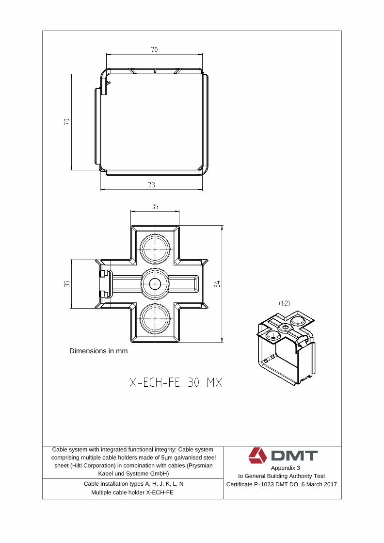
4.3.1 Cable installation type A: Hilti multiple cable holder X-ECH-FE 30 MX ceiling installation; 2.7 kg/m; .............................................................................................. 12
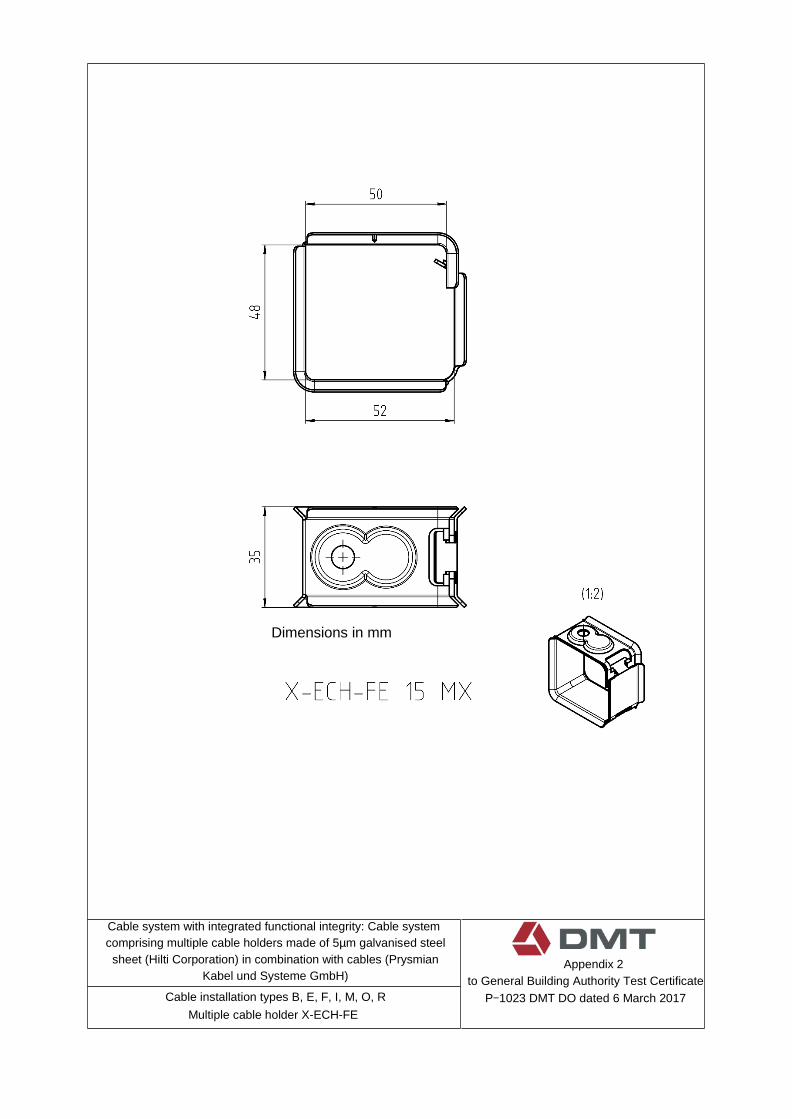
4.3.2 Cable installation type B: Hilti multiple cable holder X-ECH-FE 15 MX ceiling installation; 1.3 kg/m; .............................................................................................. 13
4.3.3 Cable installation type C: Hilti multiple cable holder X-EKB-FE 15 MX ceiling installation; 2.7 kg/m; .............................................................................................. 13
4.3.4 Cable installation type D: Hilti multiple cable holder X-EKB-FE 8 MX ceiling installation; 1.3 kg/m; .............................................................................................. 13
4.3.5 Cable installation type E: Hilti multiple cable holder X-ECH-FE 15 MX wall installation; 1.3 kg/m; .............................................................................................. 14
4.3.6 Cable installation type F: Hilti multiple cable holder X-ECH-FE 15 MX ceiling installation; 3.0 kg/m; .............................................................................................. 14
4.3.7 Cable installation type G: Hilti multiple cable holder X-EKB-FE 8 MX ceiling installation; 2.9 kg/m; .............................................................................................. 15
4.3.8 Cable installation type H: Hilti multiple cable holder X-ECH-FE 30 MX wall installation; 2.7 kg/m; .............................................................................................. 15
4.3.9 Cable installation type I: Hilti multiple cable holder X-ECH-FE 15 MX ceiling installation; 3.5 kg/m; .............................................................................................. 15
4.3.10 Cable installation type J: Hilti multiple cable holder X-ECH-FE 30 MX ceiling installation; 4.0 kg/m; .............................................................................................. 16
4.3.11 Cable installation type K: Hilti multiple cable holder X-ECH-FE 30 MX wall installation; 4.0 kg/m; .............................................................................................. 16
4.3.12 Cable installation type L: Hilti multiple cable holder X-ECH-FE 30 MX ceiling installation; 3.6 kg/m; .............................................................................................. 16
4.3.13 Cable installation type M: Hilti multiple cable holder X-ECH-FE 15 MX ceiling installation; 2.8 kg/m; .............................................................................................. 17
4.3.14 Cable installation type N: Hilti multiple cable holder X-ECH-FE 30 MX wall installation; 3.6 kg/m; .............................................................................................. 17
4.3.15 Cable installation type O: Hilti multiple cable holder X-ECH-FE 15 MX ceiling installation; 2.6 kg/m; .............................................................................................. 18
4.3.16 Cable installation type P: Hilti multiple cable holder X-EKB-FE 15 MX ceiling installation; 3.3 kg/m; .............................................................................................. 18
4.3.17 Cable installation type Q: Hilti multiple cable holder X-EKB-FE 8 MX ceiling installation; 2.95 kg/m; .............................................................................................. 18
4.3.18 Cable installation type R: Hilti multiple cable holder X-ECH-FE 15 MX wall installation; 2.6 kg/m; .............................................................................................. 19

DMT GmbH & Co. KG Plant and Product Safety – Testing Centre for Fire Protection General building authority test certificate
P-1023 DMT DO dated 6 March 2017
Page 4 of 34
5 Maintenance and servicing of the construction product ................................................ 20
6 Legal basis ......................................................................................................................... 21
7 Legal remedies .................................................................................................................. 21
Appendix 1
Appendix 2
Appendix 3
Appendix 4
Appendix 5
Appendix 6
Appendix 7
Appendix 8
Appendix 9
Appendix 10
Appendix 11
Appendix 12
Appendix 13

DMT GmbH & Co. KG Plant and Product Safety – Testing Centre for Fire Protection General building authority test certificate
P-1023 DMT DO dated 6 March 2017
Page 5 of 34
1 General provisions
■ This general building authority test certificate proves that the construction type that is the subject of the certificate is suitable for use as per the German state building regulations.
■ The general building authority test certificate is not a substitute for any permits, approvals or certificates that are required by law for the purpose of implementing construction projects.
■ The general building authority test certificate is issued without prejudice to the rights of third parties, in particular, private property rights.
■ The producer and seller of the construction type shall, notwithstanding any more extensive provisions under “Special Provisions”, make copies of the general building authority test certificate available to the user/implementer of the construction product and draw his attention to the fact that a copy of the general building authority test certificate must be kept at the site of use. The relevant authorities shall be provided with copies of the general building authority test certificate upon request.
■ The general building authority test certificate may only be reproduced in full. Extracts may only be published with the approval of DMT GmbH & Co. KG, Testing Centre for Fire Protection. Advertising text and drawings must not contradict the general building authority test certificate. Translated versions of the general building authority test certificate must be marked with the words “Translated from the original German version, but not verified by DMT GmbH & Co. KG, Testing Centre for Fire Protection” in both the German language and the language of the translation.
■ The general building authority test certificate may be revoked after issue. The provisions of this certificate may be subsequently supplemented or modified, particularly in the light of new developments in technology.
■ The construction product that is the test subject of the general building authority test certificate requires proof of conformity (Certificate of Conformity) and must bear the German Mark of Conformity (“Ü”) as per the mark of conformity regulations of the German states.
2 Special provisions
2.1 Test subject and scope/fields of application
2.1.1 Test subject
This general building authority test certificate in accordance with Building Rules List A, Part 3, Number 2.9 Edition 2015/2 “Electrical cable system types which are subject to requirements regarding functional integrity maintenance under the influence of fire” applies to the manufacture and use of cable systems as a construction type. Depending on the cable types in combination with the support systems, the cable system with integrated functional integrity ensures classification in functional integrity maintenance classes “E30”, “E60” and “E90” as per DIN 4102-12:1998-11.
DMT GmbH & Co. KG Plant and Product Safety – Testing Centre for Fire Protection General building authority test certificate
P-1023 DMT DO dated 6 March 2017
Page 6 of 34
The cable system with integrated functional integrity must be made up of cable construction
types in accordance with Section 4.2 and support systems in accordance with Section 4.3.
2.1.2 Scope/fields of application
The scope of application is limited to cables with a nominal voltage ≤ 1 kV. When
dimensioning cable systems with integrated functional integrity, possible impairment of
the function due to an increase in resistance caused by thermal factors must be take
into consideration.
The cable system with integrated functional integrity is to be assigned to functional
integrity maintenance class “E30”, “E60” or “E90”, if the cable construction types and
dimensions shown in Table 1 are used with the corresponding support systems.
The cable system with integrated functional integrity must be fixed to
solid walls made of masonry as per DIN 1053-1 to -4, made of concrete or reinforced
concrete as per DIN 1045, or aerated concrete panels to DIN 4166
or
ceilings made of concrete or reinforced concrete as per DIN 1045 or aerated concrete to
DIN 4223, whose fire resistance class in accordance with DIN 4102-2 at least matches the
functional integrity maintenance class of the cable system with integrated functional
integrity.
If fixed to other construction components than those named above, the applicability must
be verified separately, e.g. with a general building authority test certificate.
A combination of different cable installation types within a cable system according to
4.3 is permitted provided that these types are assigned to the same functional
integrity maintenance classes.
In the case of inclined or vertical cable systems with integrated functional integrity, the
cables in the transition area from vertical to horizontal must be supported in order to
prevent any slipping or kinking of the cables at edges.
The applicant has declared that, in the construction type, no products are used that are
subject to the German Ordinance on Hazardous Substances, the German Chemicals
Prohibition Ordinance, or the German Ordinance for the Prohibition of CFCs and
Halons, or that the requirements of these ordinances (particularly with regard to
labelling) have been met.

DMT GmbH & Co. KG Plant and Product Safety – Testing Centre for Fire Protection General building authority test certificate
P-1023 DMT DO dated 6 March 2017
Page 7 of 34
The applicant has also declared that – insofar as measures relating to hygiene, health
and safety or environmental protection need to be met for trading, introduction to the
market or use – these measures will be initiated/made public in the necessary manner
by the applicant.
Based on the above-mentioned declaration made by the applicant, there was no reason
to examine the effects of the construction product in its installed condition about
compliance with health, safety and environmental protection requirements.
This general building authority test certificate considers the construction product only
with regard to its fire protection properties (other aspects such as acoustic and thermal
insulation or stability are not examined).
If other requirements apply to the cable system or individual parts of the cable system,
these must be verified separately.
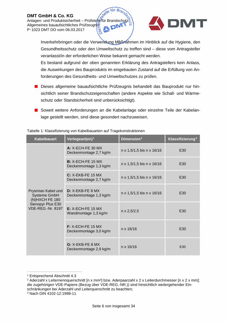
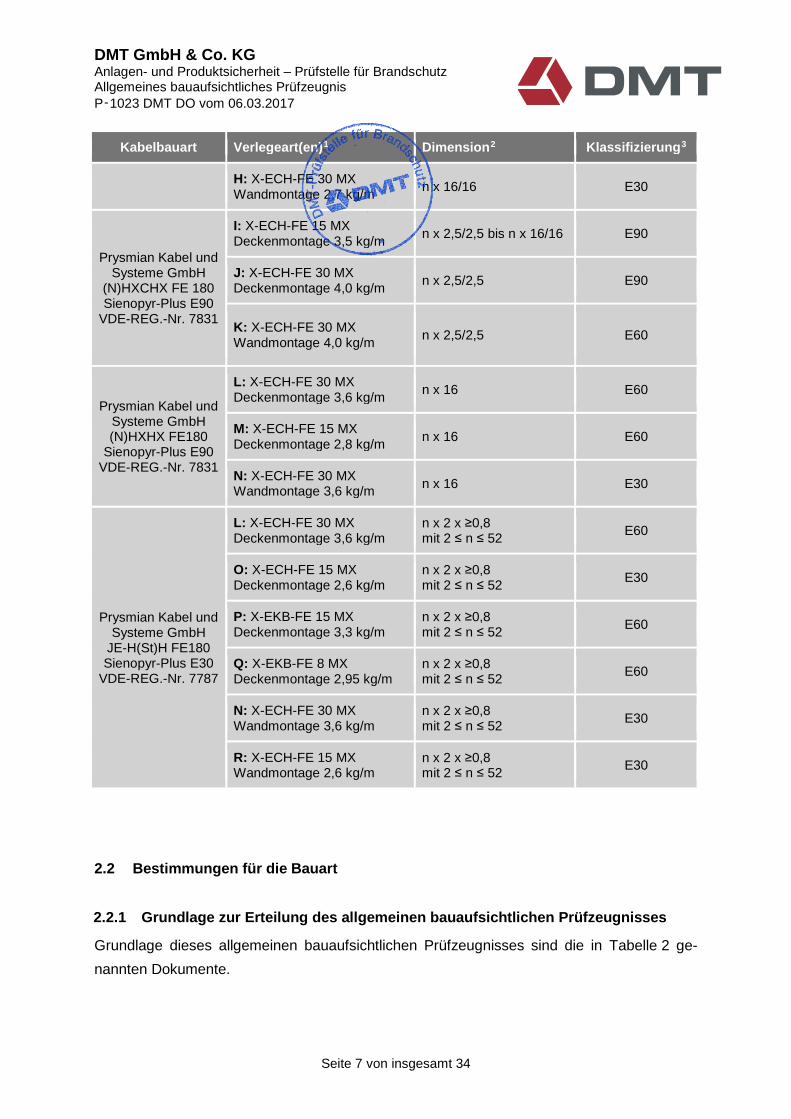
Table 1: Classification of cable types on support constructions
Cable type Cable installation type(s)1 Dimensions2 Classification3
A: X-ECH-FE 30 MX
Ceiling installation 2.7 kg/m
n x 1.5/1.5 to n x 16/16
E30
B: X-ECH-FE 15 MX
Ceiling installation 1.3 kg/m
n x 1.5/1.5 to n x 16/16
E30
C: X-EKB-FE 15 MX
Ceiling installation 2.7 kg/m
n x 1.5/1.5 to n x 16/16
E30
Prysmian Kabel und Systeme GmbH
(N)HXCH FE 180
D: X-EKB-FE 8 MX
Ceiling installation 1.3 kg/m
n x 1.5/1.5 to n x 16/16
E30
Sienopyr Plus E30 VDE-REG.-No. 8197 E: X-ECH-FE 15 MX
Wall installation 1.3 kg/m
n x 2.5/2.5
E30
F: X-ECH-FE 15 MX
Ceiling installation 3.0 kg/m
n x 16/16
E30
G: X-EKB-FE 8 MX
Ceiling installation 2.9 kg/m
n x 16/16
E30
1 In accordance with Section 4.3. 2 Number of conductors x conductor cross-section [n x mm²] or number of conductor pairs x 2 x conductor diameter [n x 2 x mm]; the associated VDE papers (reference via VDE-REG.-NO.) must be observed with regard to any more extensive restrictions regarding the number of conductors and conductor cross section; 3 According to DIN 4102-12:1998-11

DMT GmbH & Co. KG Plant and Product Safety – Testing Centre for Fire Protection General building authority test certificate
P-1023 DMT DO dated 6 March 2017
Page 8 of 34
Prysmian Kabel and
Sienopyr-Plus E90
JE-H(St)H FE180
2.2 Provisions for the construction type
2.2.1 The basis for issuing the general building authority test certificate
The documents listed in Table 2 form the basis of this general building authority test certificate.
Cable type Cable installation type(s)1 Dimensions2 Classification3
H: X-ECH-FE 30 MX Wall installation 2.7 kg/m
n x 16/16
E30
I: X-ECH-FE 15 MX
Ceiling installation 3.5 kg/m
n x 2.5/2.5 to n x 16/16
E90
Systeme GmbH (N)HXCHX FE 180
J: X-ECH-FE 30 MX
Ceiling installation 4.0 kg/m
n x 2.5/2.5
E90
VDE-REG.-No. 7831
K: X-ECH-FE 30 MX
Wall installation 4.0 kg/m
n x 2.5/2.5
E60
Prysmian Kabel und
L: X-ECH-FE 30 MX
Ceiling installation 3.6 kg/m
n x 16
E60
Systeme GmbH (N)HXHX FE180
Sienopyr-Plus E90
M: X-ECH-FE 15 MX
Ceiling installation 2.8 kg/m
n x 16
E60
VDE-REG.-No. 7831 N: X-ECH-FE 30 MX
Wall installation 3.6 kg/m
n x 16
E30
L: X-ECH-FE 30 MX
Ceiling installation 3.6 kg/m n x 2 x ≥ 0.8 where 2 ≤ n ≤ 52
E60
O: X-ECH-FE 15 MX Ceiling installation 2.6 kg/m
n x 2 x ≥ 0.8 where 2 ≤ n ≤ 52
E30
Prysmian Kabel und Systeme GmbH
P: X-EKB-FE 15 MX
Ceiling installation 3.3 kg/m n x 2 x ≥ 0.8 where 2 ≤ n ≤ 52
E60
Sienopyr-Plus E30 VDE-REG.-No. 7787
Q: X-EKB-FE 8 MX
Ceiling installation 2.95 kg/m n x 2 x ≥ 0.8 where 2 ≤ n ≤ 52
E60
N: X-ECH-FE 30 MX
Wall installation 3.6 kg/m n x 2 x ≥ 0.8 where 2 ≤ n ≤ 52
E30
R: X-ECH-FE 15 MX Wall installation 2.6 kg/m
n x 2 x ≥ 0.8 where 2 ≤ n ≤ 52
E30

DMT GmbH & Co. KG Plant and Product Safety – Testing Centre for Fire Protection General building authority test certificate
P-1023 DMT DO dated 6 March 2017
Page 9 of 34
Table 2: Documents used in preparing this test certificate
Document title Reference date Test subject Issuer/Testing centre
1 Application for a general building authority test certificate
15.09.2016 Application and formal declarations/assurances
Hilti Corporation
2 Test report DMT-31/87 20661065
17.01.2017 Testing in accordance with DIN 4102-12
DMT Testing Centre for Fire Protection, NRW 49
3 Test report DMT-31/88 20661065
17.01.2017 Testing in accordance with DIN 4102-12
DMT Testing Centre for Fire Protection, NRW 49
4 Test report DMT-31/89 20661065
17.01.2017 Testing in accordance with DIN 4102-12
DMT Testing Centre for Fire Protection, NRW 49
5 Expert’s report with production monitoring; REG. No. 8197; ID number 400021371; file reference 2306700-5929- 0604 / 215086
2007-06-28;
last changed on 2015-12-21
Expert’s report with production monitoring
VDE Testing and Certification Institute
6 Expert’s report with production monitoring; REG. No. 7831; ID number 40006409; file reference 2306700-5920- 0030 / 232515
2003-05-22;
last changed on 2016-12-22
Expert’s report with production monitoring
VDE Testing and Certification Institute
7 Expert’s report with production monitoring; REG. No. 7787; ID number 40042004; file reference 2306700-5350-
0022 / 187856
2015-04-07; Expert’s report with production monitoring
VDE Testing and Certification Institute
8 Summarised assessment 20661065
20.01.2017 Summarised assessment for P-1023 DMT DO
DMT Testing Centre for Fire Protection, NRW 49
9 Investigation report (2101/681/16) – CM dated 07.12.2016
07.12.2016 Testing of Hilti nails set in reinforced concrete ceiling sections and loaded, to determine the behaviour in fire and the fire resistance period when subjected to fire from one side
iBMB MPA Braunschweig at the Technische Universität Braunschweig, Material Testing Institute for the Construction Industry
This general building authority test certificate was assessed and prepared according to the
resolutions of the ABM “Construction Components” working group. The results are presented in
a summarised assessment '20661065 for P-1023 DMT-DO' dated 20.01.2017. This assessment
has not been published and kept at the testing centre.

DMT GmbH & Co. KG Plant and Product Safety – Testing Centre for Fire Protection General building authority test certificate
P-1023 DMT DO dated 6 March 2017
Page 10 of 34
2.2.2 Labelling
Each cable system must be permanently labelled as described below. If it is not possible to
label the cable system itself, then the label must be affixed nearby, where it can be easily
associated with the system. Labelling should be permanent, by means of a plate or sticker.
The label must include the following information:
The name of the company that fabricated the cable system
Product designation: Cable system comprising multiple cable holders made of 5µm
galvanised steel sheet (Hilti Corporation) in combination with cables (Prysmian Kabel
und Systeme GmbH)
Name of the fabricator of the cable system
Text: “Cable system with integrated functional integrity E30/E60/E904 as per DIN
4102-12:1998-11”
Test certificate number: “P-1023 DMT DO dated 06.03.2017”
Text: “Holder of the certificate: Hilti Corporation”
Text: “Testing centre: DMT GmbH & Co. KG, Testing Centre for Fire Protection”
Production year/batch designation
The label may be applied only if the requirements according to Section 3 with regard to the
certificate of conformity have been met.
3 Certificate of conformity
The construction type that is the subject of this general building authority test certificate
requires proof of conformity (Certificate of Conformity) in the form of a declaration of conformity
provided by the user (installer) in accordance with Building Rules List A, Part 3, Number 2.9
Edition 2015/2.
4Details of the actual functional integrity maintenance class according to Table 1

DMT GmbH & Co. KG Plant and Product Safety – Testing Centre for Fire Protection General building authority test certificate
P-1023 DMT DO dated 6 March 2017
Page 11 of 34
The installer who assembles the cable system with integrated functional integrity must provide
the customer with a declaration of conformity (see the template in Appendix 1), which certifies
that the cable system with integrated functional integrity that he provides complies with the
provisions of this general building authority test certificate.
4 Provisions for installation
4.1 General
The building owner or his representatives involved in the construction are responsible
for the stability and safe implementation when using the construction type, including all
fixings. Neither the stability nor the design and implementation of the fixings for the
construction product were included in the tests upon which this general building
authority test certificate is based.
The construction product must not be used if requirements with regard to the formation of
toxic gases in the event of fire need to be met.
It must be ensured that the cable system with integrated functional integrity is not
adversely affected by surrounding components in the event of fire for the duration
corresponding to their functional integrity class.
The maximum load due to the weight of the cables must not exceed the values
specified in Section 4.3.
When using several cable systems arranged vertically one above the other on the wall,
according to this usability certificate, the minimum vertical distance of 240 mm between
the individual cable systems must be maintained.
Suspension rods, multiple cable holders, pipe clamps, hook rails and other construction
components under tension must be dimensioned to have a calculated tensile stress ≤ 9
N/mm² (classification “E30” and “E60”) or ≤ 6 N/mm² (classification “E90”) as per DIN
4102-4:1994-03, Table 109. Construction components under shear loading must be
dimensioned to have a calculated shear stress ≤ 15 N/mm² (classification “E30” and
“E60”) or ≤ 10 N/mm² (classification “E90”) as per DIN 4102-4:1994-03, Table 109.
The multiple cable holders “X-ECH-FE 15 MX”, “X-ECH-FE 30 MX”, “X-EKB-FE 8 MX”
and “X-EKB-FE 15 MX” described in this document can be mounted on reinforced
concrete with a strength class of C20/25 to C50/60 using the nail installation method
outlined below. The following boundary conditions must be observed:

DMT GmbH & Co. KG Plant and Product Safety – Testing Centre for Fire Protection General building authority test certificate
P-1023 DMT DO dated 6 March 2017
Page 12 of 34
o The nails must be driven in through the sheet metal through the nail fixing points
marked with indentations on the cable holders (“X-ECH-FE 15 MX” 1 nail, “X-
ECH-FE 30 MX” 2 nails, “X-EKB-FE 8 MX” 1 nail or “X-EKB-FE 15 MX” 1 nail);
o Use a suitable combination of setting tool and nails:
Hilti setting tool “BX3-ME” (electrically operated) with Hilti “X-P 17 B3 MX” nails made of carbon steel HRC 57.5 galvanised (2-10µm), total length 18.8 mm, diameter 3 mm; longer, suitable nails in accordance with Appendix 13 are also possible as an alternative;
or
Hilti setting tool “GX3-ME” (gas operated) with Hilti “X-P 17 G3 MX” nails made
of carbon steel HRC 57.5 galvanised (2-10µm), total length 18.8 mm, diameter
3 mm; longer, suitable nails in accordance with Appendix 13 are also possible
as an alternative;
or
Hilti setting tool “GX 120 ME” (gas operated) with Hilti “X-GHP 18 MX” nails
made of carbon steel HRC 57.5 galvanised (2-10µm), total length 19.8 mm,
diameter 3 mm; longer, suitable nails in accordance with Appendix 13 are also
possible as an alternative;
o The following values must be complied with during installation:
Anchor depth hnom of the nail in the load-
bearing reinforced concrete substrate:
hnom≥ 12 mm
Protrusion P of the nail head above
the substrate:
2 mm ≤ P ≤ 5 mm
Minimum thickness hmin of the substrate: hmin ≥ 60 mm
o The load per nail resulting from the weight of the multiple cable holder itself and
the line load of the cables must not exceed 20 N;
o Observe the installation guidelines and manufacturer’s instructions as well as
appendices 10 onwards of this document;
o Cable systems installed using nails must not be exposed to natural weather or
humid ambient conditions;
As an alternative to using nails, the cable support systems can be fixed to solid building
components, i.e. solid ceilings or solid walls, using steel expansion anchors ≥ M6 that
are suitable for the type of substrate.
DMT GmbH & Co. KG Plant and Product Safety – Testing Centre for Fire Protection General building authority test certificate
P-1023 DMT DO dated 6 March 2017
Page 13 of 34
Anchors that have no proof of suitability for fire protection must comply with the
specifications of the applicable general technical approvals issued by the Deutsches
Institut für Bautechnik (DIBt), Berlin, and must also be installed twice as deep as
specified in the approval notice - and at least 60 mm deep in all cases - unless
otherwise stated in the approval. The calculated tensile load per anchor must not
exceed 500 N (see DIN 4102-4:1994-03, Section 8.5.7.5). Alternatively, anchors may
be used whose suitability with regard to fire protection has been proven for the
duration corresponding to the classification of the cable system by means of a
general technical approval, a European technical approval or a general building
authority test certificate. They must be installed in accordance with the specifications
of the general technical approval or of the general building authority test certificate.
When using the multiple cable holders described here, it is not possible to combine
“cables for cable systems with integrated functional integrity” and other cables (e.g.
PVC cables) which are not subject to fire protection requirements.
Installation using connecting elements is not covered by this general building
authority test certificate.
4.2 Cable types
Only cable types from the manufacturer PRYSMIAN Kabel und Systeme GmbH,
Austrasse 99, 96465 Neustadt, Germany, according to Table 1 may be used, which
have a valid VDE approval or expert’s report with production monitoring.
The cable must be labelled in accordance with the VDE regulations.
4.3 Cable support systems
4.3.1 Cable installation type A: Hilti multiple cable holder X-ECH-FE 30 MX Ceiling installation; 2.7 kg/m;
Installation type A support constructions made of components from the “Hilti Corporation” must be
installed as follows:
Multiple cable holder X-ECH-FE 30 MX;
Multiple cable holders fixed in the ceiling;
Distance between the multiple cable holders in the direction of laying: nominal value 600 mm;

DMT GmbH & Co. KG Plant and Product Safety – Testing Centre for Fire Protection General building authority test certificate
P-1023 DMT DO dated 6 March 2017
Page 14 of 34
A row of multiple cable holders can be loaded with a line load of ≤ 2.7 kg/m in the direction of laying;
See the appendices for further design details of the cable support construction.
4.3.2 Cable installation type B: Hilti multiple cable holder X-ECH-FE 15 MX
Ceiling installation; 1.3 kg/m;
Installation type B support constructions made of components from the “Hilti Corporation” must be
installed as follows:
Multiple cable holder X-ECH-FE 15 MX;
Multiple cable holders fixed in the ceiling;
Spacing between the multiple cable holders in the direction of laying: nominal value 600 mm;
A row of multiple cable holders can be loaded with a line load of ≤ 1.3 kg/m in the direction of laying;
See the appendices for further design details of the cable support construction.
4.3.3 Cable installation type C: Hilti multiple cable holder X-EKB-FE 15 MX
Ceiling installation; 2.7 kg/m;
Installation type C support constructions made of components from the “Hilti Corporation”
must be installed as follows:
Multiple cable holder X-EKB-FE 15 MX;
Multiple cable holders fixed in the ceiling;
Spacing between the multiple cable holders in the direction of laying: nominal value 600 mm;
A row of multiple cable holders can be loaded with a line load of ≤ 2.7 kg/m in the direction of laying;
See the appendices for further design details of the cable support construction.
4.3.4 Cable installation type D: Hilti multiple cable holder X-EKB-FE 8 MX
Ceiling installation; 1.3 kg/m;
Installation type D support constructions made of components from the “Hilti Corporation”
must be installed as follows:

DMT GmbH & Co. KG Plant and Product Safety – Testing Centre for Fire Protection General building authority test certificate
P-1023 DMT DO dated 6 March 2017
Page 15 of 34
Multiple cable holder X-EKB-FE 8 MX;
Multiple cable holders fixed in the ceiling;
Spacing between the multiple cable holders in the direction of laying: nominal value 600 mm;
A row of multiple cable holders can be loaded with a line load of ≤ 1.3 kg/m in the direction of laying;
See the appendices for further design details of the cable support construction.
4.3.5 Cable installation type E: Hilti multiple cable holder X-ECH-FE 15 MX
Wall installation; 1.3 kg/m;
Installation type E support constructions made of components from the “Hilti Corporation” must be
installed as follows:
Multiple cable holder X-ECH-FE 15 MX;
Multiple cable holders fixed in the wall;
Spacing between the multiple cable holders in the direction of laying: nominal value 600 mm;
A row of multiple cable holders can be loaded with a line load of ≤ 1.3 kg/m in the direction of laying;
See the appendices for further design details of the cable support construction.
4.3.6 Cable installation type F: Hilti multiple cable holder X-ECH-FE 15 MX
Ceiling installation; 3.0 kg/m;
Installation type F support constructions made of components from the “Hilti Corporation” must be
installed as follows:
Multiple cable holder X-ECH-FE 15 MX;
Multiple cable holders fixed in the ceiling;
Spacing between the multiple cable holders in the direction of laying: nominal value 600 mm;
A row of multiple cable holders can be loaded with a line load of ≤ 3.0 kg/m in the direction of laying;
See the appendices for further design details of the cable support construction.

DMT GmbH & Co. KG Plant and Product Safety – Testing Centre for Fire Protection General building authority test certificate
P-1023 DMT DO dated 6 March 2017
Page 16 of 34
4.3.7 Cable installation type G: Hilti multiple cable holder X-EKB-FE 8 MX Ceiling installation; 2.9 kg/m;
Installation type G support constructions made of components from the “Hilti Corporation”
must be installed as follows:
Multiple cable holder X-EKB-FE 8 MX;
Multiple cable holders fixed in the ceiling;
Spacing between the multiple cable holders in direction of laying: nominal value 600 mm;
A row of multiple cable holders can be loaded with a line load of ≤ 2.9 kg/m in the direction of laying;
See the appendices for further design details of the cable support construction.
4.3.8 Cable installation type H: Hilti multiple cable holder X-ECH-FE 30 MX
Wall installation; 2.7 kg/m;
Installation type H support constructions made of components from the “Hilti Corporation”
must be installed as follows:
Multiple cable holder X-ECH-FE 30 MX;
Multiple cable holders fixed in the wall;
Spacing between the multiple cable holders in the direction of laying: nominal value 600 mm;
A row of multiple cable holders can be loaded with a line load of ≤ 2.7 kg/m in the direction of laying;
See the appendices for further design details of the cable support construction.
4.3.9 Cable installation type I: Hilti multiple cable holder X-ECH-FE 15 MX
Ceiling installation; 3.5 kg/m;
Installation type I support constructions made of components from the “Hilti Corporation” must be
installed as follows:
Multiple cable holder X-ECH-FE 15 MX;
Multiple cable holders fixed in the ceiling;
Spacing between the multiple cable holders in the direction of laying: nominal value 600 mm;

DMT GmbH & Co. KG Plant and Product Safety – Testing Centre for Fire Protection General building authority test certificate
P-1023 DMT DO dated 6 March 2017
Page 17 of 34
A row of multiple cable holders can be loaded with a line load of ≤ 3.5 kg/m in the direction of laying;
See the appendices for further design details of the cable support construction.
4.3.10 Cable installation type J: Hilti multiple cable holder X-ECH-FE 30 MX
Ceiling installation; 4.0 kg/m;
Installation type J support constructions made of components from the “Hilti Corporation” must be
installed as follows:
Multiple cable holder X-ECH-FE 30 MX;
Multiple cable holders fixed in the ceiling;
Spacing between the multiple cable holders in the direction of laying: nominal value 600 mm;
A row of multiple cable holders can be loaded with a line load of ≤ 4.0 kg/m in the direction of laying;
See the appendices for further design details of the cable support construction.
4.3.11 Cable installation type K: Hilti multiple cable holder X-ECH-FE 30 MX
Wall installation; 4.0 kg/m;
Installation type K support constructions made of components from the “Hilti Corporation” must be
installed as follows:
Multiple cable holder X-ECH-FE 30 MX;
Multiple cable holders fixed in the wall;
Spacing between the multiple cable holders in the direction of laying: nominal value 600 mm;
A row of multiple cable holders can be loaded with a line load of ≤ 4.0 kg/m in the direction of laying;
See the appendices for further design details of the cable support construction.
4.3.12 Cable installation type L: Hilti multiple cable holder X-ECH-FE 30 MX
Ceiling installation; 3.6 kg/m;
Installation type L support constructions made of components from the “Hilti Corporation” must be
installed as follows:
DMT GmbH & Co. KG Plant and Product Safety – Testing Centre for Fire Protection General building authority test certificate
P-1023 DMT DO dated 6 March 2017
Page 18 of 34
Multiple cable holder X-ECH-FE 30 MX;
Multiple cable holders fixed in the ceiling;
Spacing between the multiple cable holders in the direction of laying: nominal value 600 mm;
A row of multiple cable holders can be loaded with a line load of ≤ 3.6 kg/m in the direction of laying;
See the appendices for further design details of the cable support construction.
4.3.13 Cable installation type M: Hilti multiple cable holder X-ECH-FE 15 MX
Ceiling installation; 2.8 kg/m;
Installation type M support constructions made of components from the “Hilti Corporation”
must be installed as follows:
Multiple cable holder X-ECH-FE 15 MX;
Multiple cable holders fixed in the ceiling;
Spacing between the multiple cable holders in the direction of laying: nominal value 600 mm;
A row of multiple cable holders can be loaded with a line load of ≤ 2.8 kg/m in the direction of laying;
See the appendices for further design details of the cable support construction.
4.3.14 Cable installation type N: Hilti multiple cable holder X-ECH-FE 30 MX
Wall installation; 3.6 kg/m;
Installation type N support constructions made of components from the “Hilti Corporation”
must be installed as follows:
Multiple cable holder X-ECH-FE 30 MX;
Multiple cable holders fixed in the wall;
Spacing between the multiple cable holders in the direction of laying: nominal value 600 mm;
A row of multiple cable holders can be loaded with a line load of ≤ 3.6 kg/m in the direction of laying;
See the appendices for further design details of the cable support construction.

DMT GmbH & Co. KG Plant and Product Safety – Testing Centre for Fire Protection General building authority test certificate
P-1023 DMT DO dated 6 March 2017
Page 19 of 34
4.3.15 Cable installation type O: Hilti multiple cable holder X-ECH-FE 15 MX ceiling installation; 2.6 kg/m;
Installation type O support constructions made of components from the “Hilti Corporation”
must be installed as follows:
Multiple cable holder X-ECH-FE 15 MX;
Multiple cable holders fixed in the ceiling;
Spacing between the multiple cable holders in the direction of laying: nominal value 600 mm;
A row of multiple cable holders can be loaded with a line load of ≤ 2.6 kg/m in the direction of laying;
See the appendices for further design details of the cable support construction.
4.3.16 Cable installation type P: Hilti multiple cable holder X-EKB-FE 15 MX
Ceiling installation; 3.3 kg/m;
Installation type P support constructions made of components from the “Hilti Corporation” must be
installed as follows:
Multiple cable holder X-EKB-FE 15 MX;
Multiple cable holders fixed in the ceiling;
Spacing between the multiple cable holders in the direction of laying: nominal value 600 mm;
A row of multiple cable holders can be loaded with a line load of ≤ 3.3 kg/m in the direction of laying;
See the appendices for further design details of the cable support construction.
4.3.17 Cable installation type Q: Hilti multiple cable holder X-EKB-FE 8 MX
Ceiling installation; 2.95 kg/m;
Installation type Q support constructions made of components from the “Hilti Corporation”
must be installed as follows:
Multiple cable holder X-EKB-FE 8 MX;
Multiple cable holders fixed in the ceiling;
Spacing between the multiple cable holders in the direction of laying: nominal value 600 mm;

DMT GmbH & Co. KG Plant and Product Safety – Testing Centre for Fire Protection General building authority test certificate
P-1023 DMT DO dated 6 March 2017
Page 20 of 34
A row of multiple cable holders can be loaded with a line load of ≤ 2.95 kg/m in the
direction of laying;
See the appendices for further design details of the cable support construction.
4.3.18 Cable installation type R: Hilti multiple cable holder X-ECH-FE 15 MX
Wall installation; 2.6 kg/m;
Installation type R support constructions made of components from the “Hilti Corporation”
must be installed as follows:
Multiple cable holder X-ECH-FE 15 MX;
Multiple cable holders fixed in the wall;
Spacing between the multiple cable holders in the direction of laying: nominal value
600 mm;
A row of multiple cable holders can be loaded with a line load of ≤ 2.6 kg/m in the direction
of laying;
See the appendices for further design details of the cable support construction.
5 Maintenance and servicing of the construction product
The construction product must not be subjected to any additional loading or loading
other than for the intended purpose. In the accompanying documentation, the
manufacturer must describe the intended use, which does not cause the properties of
the building product to be negatively affected.
The building product must not be exposed to aggressive/harsh chemicals/detergents
during use. In the accompanying documents, the manufacturer must indicate the
cleaning methods and agents that can be used without adversely affecting the
properties of the building product.
If significant deterioration of the properties of the building product over time cannot be
ruled out, the manufacturer must indicate the maximum service life of the building
product.
For each version of the cable system with integrated functional integrity, the installer
must point out to the customer that the fire protection effect of the cable system with
integrated functional integrity is only guaranteed in the long term if the cable system,
i.e. the cable types and the cable support construction, is always kept in proper condition
and is restored to its intended condition after the addition of any further cables.

DMT GmbH & Co. KG Plant and Product Safety – Testing Centre for Fire Protection General building authority test certificate
P-1023 DMT DO dated 6 March 2017
Page 21 of 34
6 Legal basis
This general building authority test certificate is issued on the basis of § 20, Paragraph 3,
Number 2 in conjunction with § 22 BauO NW state building regulations in conjunction with
Building Rules List A, Part 3, Number 2.9, published 2015/2. The state building regulations of
the other federal states, § 19, Paragraph 2, Sentence 2 in conjunction with § 18, Paragraph 7
of the Musterbauordung (Standard Building Regulations) dated November 2002, last amended
by the resolution of the Bauministerkonferenz (Conference of Construction Ministers) of May
2016, contain corresponding legal frameworks that also regulate the recognition of general
building authority test certificates issued by the testing bodies of other states.
7 Legal remedies
An action may be brought against this decision within one month of its notification. The action
must be filed in writing or recorded at the Administrative Court of Gelsenkirchen,
Bahnhofvorplatz 3, 45879 Gelsenkirchen, Germany.
The action can also be filed in electronic form in accordance with the Ordinance on Electronic
Legal Transactions at the Administrative Courts and Tax Courts in the State of North Rhine-
Westphalia -ERVVO VG/FG- dated 7 November 2012 (GVNRW.2012 p. 548). In this case, the
electronic document must include a qualified signature in accordance with § 2, No. 3 of the
applicable edition of the German Signature Act of 16 May 2001 (Federal Law Gazette BGBl I
p. 876) and must be transmitted to the court's electronic mailroom.
Note: When using the electronic method, special technical requirements must be observed.
The special technical requirements are listed at www.egvp.de.

DMT GmbH & Co. KG Plant and Product Safety – Testing Centre for Fire Protection General building authority test certificate
P-1023 DMT DO dated 6 March 2017
Page 22 of 34
Dortmund, 6 March 2017
Dipl.-Ing. (FH) Nadine Niederberghaus (Deputy Director of the Testing Centre)
Ludäscher, M.Sc. (Administrator)

DECLARATION OF CONFORMITY
Name and address of the company that constructed the cable system with integrated functional integrity:
..........*
Construction site/building/property/project:
..........*
Date of construction:
..........*
Required functional integrity maintenance class of the cable system(s) with integrated
functional integrity:
E..........* according to DIN 4102-12:1998-11
Confirmation is hereby given that the cable system(s) with integrated functional integrity in accordance with the
above-specified functional integrity maintenance class has(have) been produced and installed professionally and
in compliance with all of the provisions of general building authority test certificate no. P-1023 DMT DO issued
by DMT GmbH & Co. KG, Testing Centre for Fire Protection, Dortmund, Germany, dated 6 March 2017.
For construction products or individual parts (e.g. cable types) not manufactured by the undersigned himself, this
is also hereby confirmed on the basis of [the labelling of the parts in accordance with the provisions of the general
building authority test certificate/in-house checks/corresponding written confirmations provided by the
manufacturers of the construction products or parts, which the undersigned has added to his files]**.
Location, Date Stamp and Signature
(This certificate must be handed to the building owner so
that he can forward it to the responsible building
inspection authority!)
*) To be filled out by the undersigned **) Delete as applicable
Cable system with integrated functional integrity: Cable system
comprising multiple cable holders made of 5µm galvanised steel
sheet (Hilti Corporation) in combination with cables (Prysmian
Kabel und Systeme GmbH)
Appendix 1
to General Building Authority Test Certificate
P-1023 DMT DO dated 6 March 2017 Declaration of Conformity Template
Multiple cable holder X-ECH-FE 15 MX
Cable system with integrated functional integrity: Cable system
comprising multiple cable holders made of 5µm galvanised steel
sheet (Hilti Corporation) in combination with cables (Prysmian
Kabel und Systeme GmbH)
Cable installation types B, E, F, I, M, O, R
Appendix 2
to General Building Authority Test Certificate
P-1023 DMT DO dated 6 March 2017
Dimensions in mm
Multiple cable holder X-ECH-FE 30 MX
Cable system with integrated functional integrity: Cable system
comprising multiple cable holders made of 5µm galvanised steel
sheet (Hilti Corporation) in combination with cables (Prysmian
Kabel und Systeme GmbH)
Cable installation types A, H, J, K, L, N
Appendix 3
to General Building Authority Test
Certificate P-1023 DMT DO, 6 March 2017
Dimensions in mm
Multiple cable holder X-EKB-FE 8 MX
Cable system with integrated functional integrity: Cable system
comprising multiple cable holders made of 5µm galvanised steel
sheet (Hilti Corporation) in combination with cables (Prysmian
Kabel und Systeme GmbH)
Cable installation types D, G, Q
Appendix 4
to General Building Authority Test
Certificate P-1023 DMT DO, 6 March 2017
Dimensions in mm

Multiple cable holder X-EKB-FE 15 MX
Cable system with integrated functional integrity: Cable system
comprising multiple cable holders made of 5µm galvanised steel
sheet (Hilti Corporation) in combination with cables (Prysmian
Kabel und Systeme GmbH)
Cable installation types C, P
Appendix 5
to General Building Authority Test
Certificate P-1023 DMT DO, 6 March 2017
Dimensions in mm
Cable system with integrated functional integrity: Cable system
comprising multiple cable holders made of 5µm galvanised steel
sheet (Hilti Corporation) in combination with cables (Prysmian
Kabel und Systeme GmbH)
Cable type SIENOPYR PLUS (N)HXCH
Appendix 6
to General Building Authority Test
Certificate P-1023 DMT DO, 6 March 2017
Low voltage Halogen-free cables
(N)HXCH 0.6/1 kV
SIENOPYR-PLUS E30
Standards/Approvals > In line with DIN VDE 0266 and in line with DIN VDE 0276-604 for 1.5 mm2 to 16 mm2 DIN 4102 Part 12
Construction > Conductors Copper conductors, round, single core (RE) or round, multi core, compressed (RM)
> Insulation Double-layer insulation made of silicone and HEPR
> Core colours
2-core: blue, brown 3-core: brown, black, grey 4-core: blue, brown, black, grey Multicore: black with white numbering
> Core covering Extruded
> Concentric conductor Copper wires with helix of tape
> Outer Sheath Halogen-free flame-retardant compound, orange
Properties and applications > (N)HXCH SIENOPYR-PLUS E30 cables are intended for indoor
installation. The cables maintain functional integrity for > 30 minutes as per DIN 4102 Part 12 and thus comply with the requirements of the fire protection guidelines (standard cable system directive, German designation: MLAR). They are therefore suitable for supplying power to safety devices, e.g. in places of assembly, schools and hospitals. In accordance with DIN 4102 Part 12, SIENOPYR-PLUS E30 cables may be used only with tested installation systems (e.g. cable ladders, cable trays, and individual installation under the ceiling). The approved cable support constructions include the PSH multiple cable holders. The “general building authority test certificate” must be observed without fail during installation.
Permissible conductor
temperature in uninterrupted operation
Permissible conductor temperature during short
circuit ≤ 5 s
Functional integrity
maintained in fire ≥ 30 minutes as per DIN
4102 Part 12
Fire propagation tested to DIN EN 50266-1
and DIN EN 50266-2-4
Halogen-free Low-smoke
Lowest installation temperature -5°C
In accordance with the building
inspection authorities
test certificate
Installation
September 2009
SIE
NO
PY
R-P
LU
S E
30 (N
)HX
CH
)

Cable system with integrated functional integrity: Cable system
comprising multiple cable holders made of 5µm galvanised steel
sheet (Hilti Corporation) in combination with cables (Prysmian
Kabel und Systeme GmbH)
Cable type SIENOPYR PLUS (N)HXCHX
Appendix 7
to General Building Authority Test
Certificate P-1023 DMT DO, 6 March 2017
Permissible conductor
temperature in uninterrupted operation
Permissible conductor temperature during short
circuit ≤ 5 s
Functional integrity maintained in fire ≥ 30
minutes as per DIN 4102 Part 12
Fire propagation tested to DIN EN 50266-1
and DIN EN 50266-2-4
Halogen-free Low-smoke
Lowest installation
temperature -5°C In accordance with
the building inspection authorities
test certificate
Installation
September 2009
for 1.5 mm2 to 16 mm2 DIN 4102 Part 12
Construction > Conductors Copper conductors, round, single core (RE) or round, multi core, compressed (RM)
> Insulation Double-layer insulation made of silicone and HEPR
> Core colours
2-core: blue, brown 3-core: brown, black, grey 4-core: blue, brown, black, grey Multicore: black with white numbering
> Core covering Extruded
> Concentric conductor Copper wires with helix of tape
> Outer Sheath Halogen-free flame-retardant compound, orange
Properties and applications > (N)HXCH SIENOPYR-PLUS E30 cables are intended for indoor
installation. The cables maintain functional integrity for > 30 minutes as per DIN 4102 Part 12 and thus comply with the requirements of the fire protection guidelines (standard cable system directive, German designation: MLAR). They are therefore suitable for supplying power to safety devices, e.g. in places of assembly, schools and hospitals. In accordance with DIN 4102 Part 12, SIENOPYR-PLUS E30 cables may be used only with tested installation systems (e.g. cable ladders, cable trays, and individual installation under the ceiling). The approved cable support constructions include the PSH multiple cable holders. The “general building authority test certificate” must be observed without fail during installation.
Low voltage Halogen-free cables
(N)HXCHX 0.6/1 kV
SIENOPYR-PLUS E90
Standards/Approvals > In line with DIN VDE 0266 DIN 4102 Part 12
Construction > Conductors Copper conductors, round, single core (RE) or round, multi core, compressed (RM)
> Insulation Insulation made of silicone
> Core colours 3-core: brown, black, grey 4-core: blue, brown, black, grey Multicore: black with white numbering
> Core covering Extruded
> Concentric conductor Copper wires with helix of tape
> Outer Sheath
Halogen-free flame-retardant compound, orange
Properties and applications > (N)HXCHX SIENOPYR-PLUS E90 cables are intended for indoor installation. The cables maintain functional integrity for ≥ 90 minutes as per DIN 4102 Part 12 and thus comply with the requirements of the fire protection guidelines (standard cable system directive, German designation: MLAR). They are therefore suitable for supplying power to safety devices, e.g. in places of assembly, schools and hospitals. In accordance with DIN 4102 Part 12, SIENOPYR-PLUS E90 cables may be used only with tested installation systems (e.g. cable ladders, cable trays, and individual installation under the ceiling). The approved cable support constructions include the PSH multiple cable holders. The “general building authority test certificate” must be observed without fail during installation.
SIE
NO
PY
R-P
LU
S E
90 (N
)HX
CH
X

Cable system with integrated functional integrity: Cable system
comprising multiple cable holders made of 5µm galvanised steel
sheet (Hilti Corporation) in combination with cables (Prysmian
Kabel und Systeme GmbH)
Cable type SIENOPYR PLUS (N)HXHX
Appendix 8
to General Building Authority Test
Certificate P-1023 DMT DO, 6 March 2017
Low voltage Halogen-free cables
(N)HXHX 0.6/1 kV
SIENOPYR-PLUS E90
Standards/Approvals > In line with DIN VDE 0266 DIN 4102 Part 12
Construction > Conductors Copper conductors, round, single core (RE) or round, multi core, compressed (RM)
> Insulation Insulation made of silicone
> Core colours 1-core: (N)HXHX-O black 3-core: (N)HXHX-J green and yellow, blue, brown 4-core with reduced protective conductor: (N)HXHX-J green and yellow, brown, black, grey 4-core: (N)HXHX-J green and yellow, brown, black, grey 5-core: (N)HXHX-J green and yellow, blue, brown, black, grey Multicore: (N)HXHX-J black with white numbering, one green-and-yellow core
> Core covering Extruded for all cables with more than one core
> Outer Sheath Halogen-free flame-retardant compound, orange
Properties and applications > (N)HXHX SIENOPYR-PLUS E90 cables are intended for indoor installation. The cables maintain functional integrity for ≥ 90 minutes as per DIN 4102 Part 12 and thus comply with the requirements of the fire protection guidelines (standard cable system directive, German designation: MLAR). They are therefore suitable for supplying power to safety devices, e.g. in places of assembly, schools and hospitals. In accordance with DIN 4102 Part 12, SIENOPYR-PLUS E90 cables may be used only with tested installation systems (e.g. cable ladders, cable trays, and individual installation under the ceiling). The approved cable support constructions include the PSH multiple cable holders. The “general building authority test certificate” must be observed without fail during installation.
SIE
NO
PY
R-P
LU
S E
90 (
N)H
XH
X
Permissible conductor
temperature in uninterrupted operation
Permissible conductor temperature during short
circuit ≤ 5 s
Functional integrity
maintained in fire ≥ 30 minutes as per DIN
4102 Part 12
Fire propagation tested to DIN EN 50266-1
and DIN EN 50266-2-4
Halogen-free Low-smoke
Lowest installation
temperature -5°C In accordance with
the building inspection authorities
test certificate
Installation
September 2009

Cable system with integrated functional integrity: Cable system
comprising multiple cable holders made of 5µm galvanised steel
sheet (Hilti Corporation) in combination with cables (Prysmian
Kabel und Systeme GmbH)
Cable type SIENOPYR PLUS HE-H(St)H
Appendix 9
to General Building Authority Test
Certificate P-1023 DMT DO, 6 March 2017
Installation cables Halogen-free cables
JE-H(ST)H Maximum 225 V
SIENOPYR-PLUS E30
Standards/Approvals > In line with DIN VDE 0815 DIN 4102 Part 12
Construction > Conductors Copper conductors, round, single wire
> Insulation Halogen-free compound (HJ1)
> Core colours
See the table “Core colours” > Stranding
2 cores to a pair, 4 pairs to a sub-unit,... x sub-units to a cable core Exception: Dimensions with 2 double cores as a star-quad
> Bundle labelling Each bundle of 4 pairs is labelled with numbered tape
> Cable core covering Plastic tape with at least 20% overlap Joint core covering made of fire-resistant tape
> Electrostatic shielding
Bare copper drain wire and plastic-laminated aluminium tape
> Outer sheath Halogen-free, flame-retardant compound (HM2), orange or red (for fire alarm cable)
Properties and applications > SIENOPYR-PLUS E3Q installation cables are intended for transmitting signals and measurement data. Installation cables for industrial electronics are primarily used inside buildings. The are not approved for laying in earth or for high-voltage purposes. In accordance with DIN 4102-12, SIENOPYR-PLUS E30 installation cables with functional integrity may be installed only in tested installation systems. The “general
building authority test certificate” is essential here.
Functional integrity
maintained in fire ≥ 30 minutes as per DIN 4102
Part 12
Fire propagation according to DIN EN
50266-1 and DIN EN 50266-2-4
Halogen-free Low-smoke Bending several times
under tension 7.5 x D Bending once with no
tension 2.5 x D
Permissible temperature range for moving state -
5°C to + 50°C
Installation
April 2009

Cable system with integrated functional integrity: Cable system
comprising multiple cable holders made of 5µm galvanised steel
sheet (Hilti Corporation) in combination with cables (Prysmian
Kabel und Systeme GmbH)
Installation using nails: “X-ECH FE 15 MX”
Appendix 10
to General Building Authority Test
Certificate P-1023 DMT DO, 6 March 2017

Cable system with integrated functional integrity: Cable system
comprising multiple cable holders made of 5µm galvanised steel
sheet (Hilti Corporation) in combination with cables (Prysmian
Kabel und Systeme GmbH)
Installation using nails: “X-ECH FE 30 MX”
Appendix 11
to General Building Authority Test
Certificate P-1023 DMT DO, 6 March 2017

Cable system with integrated functional integrity: Cable system
comprising multiple cable holders made of 5µm galvanised steel
sheet (Hilti Corporation) in combination with cables (Prysmian
Kabel und Systeme GmbH)
Installation using nails: “X-EKB-FE 8 MX” and “X-EKB FE 15 MX”
Appendix 12
to General Building Authority Test
Certificate P-1023 DMT DO, 6 March 2017
Cable system with integrated functional integrity: Cable system
comprising multiple cable holders made of 5µm galvanised steel
sheet (Hilti Corporation) in combination with cables (Prysmian
Kabel und Systeme GmbH)
Installation using nails: fastening tools and nails
Appendix 13
to General Building Authority Test
Certificate P-1023 DMT DO, 6 March 2017
BX
3-
ME
fa
ste
ni
ng t
ool
with
nails
X
-P B
3
MX
BX
3-
ME
fa
ste
ni
ng t
ool:
fully
auto
ma
tic,
mecha
nic
ally
driven
Colla
ted
nails
X
-P
17B
3
MX
, X
-P
20 B
3
BX
and
X-P
24
B3 M
X
N ail
X-
P
1 7
GX3-ME fastening tool with nails
X-P G3 MX
GX3-ME fastening tool: fully automatic,
gas driven
Colla
ted n
ails
X
-P
17G
3
MX
, X
-P
20
G3 B
X
and X
-P
24
G3 M
X
N ail
X-
P
2 0
N ail
X-
P
2 4
GX
120-
ME
fa
ste
ni
ng t
ool
with
nails
: X
-GH
P
MX
GX 120-ME fastening tool:
fully automatic, gas driven
Colla
ted n
ails
X
-GH
P
18 M
X,
X-G
HP
20 M
X
and X
-G
HP
24 M
X
N ail
X-
G H P
1 8
N ail
X-
G H P
2 0
N ail
X-
G H P
2 4

DMT GmbH & Co. KG Anlagen- und Produktsicherheit Prüfstelle für Brandschutz
Tremoniastraße 13 44137 Dortmund Deutschland
Telefon +49 231 5333-240 Telefax +49 231 5333-299 [email protected] www.dmt-group.com
TÜV NORD GROUP
Prüfzeugnis Nummer P‑1023 DMT DO
Antragsteller Hilti Corporation Feldkircherstrasse 100 FL-9494 Schaan Liechtenstein
Gegenstand Bauarten zur Herstellung von elektrischen Kabelanlagen, an die Anforderungen hinsichtlich des Funktionserhalts unter Brandein-wirkung gestellt werden der Funktionserhaltklassen „E30“, „E60“ und "E90" nach DIN 4102-12:1998-11 gemäß Bauregelliste A Teil 3 laufende Nummer 2.9 Ausgabe 2015/2, mit der/den Pro-duktbezeichnung(en):
Kabelanlage bestehend aus Kabelsammelhaltern aus 5µm galvanisch verzinktem Stahlblech (Hilti Corporation) in Ver-bindung mit Kabeln (Prysmian Kabel und Systeme GmbH)
Ausstelldatum 06.03.2017
Geltungsdauer bis 06.03.2022
Aufgrund dieses allgemeinen bauaufsichtlichen Prüfzeugnisses ist der oben genannte Gegenstand im Sinne der Landesbau-ordnung des jeweiligen Bundeslandes anwendbar.
Dieses allgemeine bauaufsichtliche Prüfzeugnis umfasst 34 Seiten inklusive Deckblatt und 13 Anlagen. Jede Seite dieses allgemeinen bauaufsichtlichen Prüfzeugnisses ist mit dem Stempel der DMT GmbH & Co. KG, Dortmund versehen. Dokumente ohne Unterschrift und Stempel haben keine Gültigkeit.
Allgemeines bauaufsichtliches Prüfzeugnis

DMT GmbH & Co. KG Anlagen- und Produktsicherheit – Prüfstelle für Brandschutz Allgemeines bauaufsichtliches Prüfzeugnis P‑1023 DMT DO vom 06.03.2017
INHALTSVERZEICHNIS SEITE
1 ALLGEMEINE BESTIMMUNGEN ................................................................................. 4
2 BESONDERE BESTIMMUNGEN .................................................................................. 4 2.1 GEGENSTAND UND ANWENDUNGSBEREICH/VERWENDUNGSBEREICH ................... 4
2.1.1 Gegenstand ....................................................................................................................... 4 2.1.2 Anwendungsbereich/Verwendungsbereich ....................................................................... 5
2.2 BESTIMMUNGEN FÜR DIE BAUART ................................................................................... 7 2.2.1 Grundlage zur Erteilung des allgemeinen bauaufsichtlichen Prüfzeugnisses ................... 7 2.2.2 Kennzeichnung .................................................................................................................. 9
3 ÜBEREINSTIMMUNGSNACHWEIS ............................................................................. 9
4 BESTIMMUNGEN FÜR DIE AUSFÜHRUNG ...............................................................10 4.1 ALLGEMEINES .................................................................................................................... 10 4.2 KABELBAUARTEN .............................................................................................................. 12 4.3 KABELTRAGSYSTEME ...................................................................................................... 12
4.3.1 Verlegeart A: Hilti Sammelhalter X-ECH-FE 30 MX Deckenmontage; 2,7 kg/m; ............ 12 4.3.2 Verlegeart B: Hilti Sammelhalter X-ECH-FE 15 MX Deckenmontage; 1,3 kg/m; ............ 13 4.3.3 Verlegeart C: Hilti Sammelhalter X-EKB-FE 15 MX Deckenmontage; 2,7 kg/m; ............ 13 4.3.4 Verlegeart D: Hilti Sammelhalter X-EKB-FE 8 MX Deckenmontage; 1,3 kg/m; .............. 13 4.3.5 Verlegeart E: Hilti Sammelhalter X-ECH-FE 15 MX Wandmontage; 1,3 kg/m; .............. 14 4.3.6 Verlegeart F: Hilti Sammelhalter X-ECH-FE 15 MX Deckenmontage; 3,0 kg/m; ............ 14 4.3.7 Verlegeart G: Hilti Sammelhalter X-EKB-FE 8 MX Deckenmontage; 2,9 kg/m; .............. 15 4.3.8 Verlegeart H: Hilti Sammelhalter X-ECH-FE 30 MX Wandmontage; 2,7 kg/m; .............. 15 4.3.9 Verlegeart I: Hilti Sammelhalter X-ECH-FE 15 MX Deckenmontage; 3,5 kg/m; ............. 15 4.3.10 Verlegeart J: Hilti Sammelhalter X-ECH-FE 30 MX Deckenmontage; 4,0 kg/m; ............ 16 4.3.11 Verlegeart K: Hilti Sammelhalter X-ECH-FE 30 MX Wandmontage; 4,0 kg/m; .............. 16 4.3.12 Verlegeart L: Hilti Sammelhalter X-ECH-FE 30 MX Deckenmontage; 3,6 kg/m; ............ 16 4.3.13 Verlegeart M: Hilti Sammelhalter X-ECH-FE 15 MX Deckenmontage; 2,8 kg/m; ........... 17 4.3.14 Verlegeart N: Hilti Sammelhalter X-ECH-FE 30 MX Wandmontage; 3,6 kg/m; .............. 17 4.3.15 Verlegeart O: Hilti Sammelhalter X-ECH-FE 15 MX Deckemontage; 2,6 kg/m; ............. 18 4.3.16 Verlegeart P: Hilti Sammelhalter X-EKB-FE 15 MX Deckenmontage; 3,3 kg/m; ............ 18 4.3.17 Verlegeart Q: Hilti Sammelhalter X-EKB-FE 8 MX Deckenmontage; 2,95 kg/m; ............ 18 4.3.18 Verlegeart R: Hilti Sammelhalter X-ECH-FE 15 MX Wandmontage; 2,6 kg/m; .............. 19
5 UNTERHALT UND WARTUNG DES BAUPRODUKTS ...............................................19
6 RECHTSGRUNDLAGE ................................................................................................20
7 RECHTSBEHELFSBELEHRUNG ................................................................................20
Anlage 1
Anlage 2
Anlage 3
Anlage 4
Anlage 5
Anlage 6
Seite 2 von insgesamt 34

DMT GmbH & Co. KG Anlagen- und Produktsicherheit – Prüfstelle für Brandschutz Allgemeines bauaufsichtliches Prüfzeugnis P‑1023 DMT DO vom 06.03.2017
Anlage 7
Anlage 8
Anlage 9
Anlage 10
Anlage 11
Anlage 12
Anlage 13
Seite 3 von insgesamt 34

DMT GmbH & Co. KG Anlagen- und Produktsicherheit – Prüfstelle für Brandschutz Allgemeines bauaufsichtliches Prüfzeugnis P‑1023 DMT DO vom 06.03.2017
1 Allgemeine Bestimmungen ■ Mit diesem allgemeinen bauaufsichtlichen Prüfzeugnis ist die Verwendbarkeit der
als Gegenstand aufgeführten Bauart im Sinne der Landesbauordnungen nachge-wiesen.
■ Das allgemeine bauaufsichtliche Prüfzeugnis ersetzt nicht die für die Durchführung von Bauvorhaben gesetzlich vorgeschriebenen Genehmigungen, Zustimmungen und Bescheinigungen.
■ Das allgemeine bauaufsichtliche Prüfzeugnis wird unbeschadet der Rechte Dritter, insbesondere privater Schutzrechte, erteilt.
■ Hersteller und Vertreiber der Bauart haben, unbeschadet weitergehender Regelun-gen in den „Besonderen Bestimmungen“, dem Verwender des Bauprodukts Kopien des allgemeinen bauaufsichtlichen Prüfzeugnisses zur Verfügung zu stellen und da-rauf hinzuweisen, dass das allgemeine bauaufsichtliche Prüfzeugnis an der Ver-wendungsstelle vorliegen muss. Auf Anforderung sind den beteiligten Behörden Ko-pien des allgemeinen bauaufsichtlichen Prüfzeugnisses zur Verfügung zu stellen.
■ Das allgemeine bauaufsichtliche Prüfzeugnis darf nur vollständig vervielfältigt wer-den. Eine auszugsweise Veröffentlichung bedarf der Zustimmung der DMT GmbH & Co. KG, Prüfstelle für Brandschutz. Texte und Zeichnungen von Werbeschriften dürfen dem allgemeinen bauaufsichtlichen Prüfzeugnis nicht wider-sprechen. Übersetzungen des allgemeinen bauaufsichtlichen Prüfzeugnisses müs-sen den Hinweis „Von der DMT GmbH & Co. KG, Prüfstelle für Brandschutz, nicht geprüfte Übersetzung der deutschen Originalfassung" in deutscher und der über-setzten Sprache enthalten.
■ Das allgemeine bauaufsichtliche Prüfzeugnis wird widerruflich erteilt. Die hierin fest-gelegten Bestimmungen können nachträglich ergänzt und geändert werden, insbe-sondere wenn neue technische Erkenntnisse dies erfordern.
■ Das als Gegenstand des allgemeinen bauaufsichtlichen Prüfzeugnisses aufgeführte Bauprodukt bedarf des Nachweises der Übereinstimmung (Übereinstimmungs-nachweis) und der Kennzeichnung mit dem Übereinstimmungszeichen (Ü-Zeichen) nach den Übereinstimmungszeichen-Verordnungen der Länder.
2 Besondere Bestimmungen
2.1 Gegenstand und Anwendungsbereich/Verwendungsbereich
2.1.1 Gegenstand
Dieses allgemeine bauaufsichtliche Prüfzeugnis gemäß Bauregelliste A, Teil 3, laufende Nummer 2.9 Ausgabe 2015/2 „Bauarten zur Herstellung von elektrischen Kabelanlagen, an die Anforderungen hinsichtlich des Funktionserhalts unter Brandeinwirkung gestellt werden“
Seite 4 von insgesamt 34

DMT GmbH & Co. KG Anlagen- und Produktsicherheit – Prüfstelle für Brandschutz Allgemeines bauaufsichtliches Prüfzeugnis P‑1023 DMT DO vom 06.03.2017
gilt für die Herstellung und Verwendung von Kabelanlagen als Bauart. Die Kabelanlage mit integriertem Funktionserhalt gewährleistet in Abhängigkeit von den Kabelbauarten in Verbin-dung mit den Tragsystemen die Einstufung in die Funktionserhaltklassen "E30", "E60" und "E90" nach DIN 4102-12:1998-11.
Die Kabelanlage mit integriertem Funktionserhalt muss aus Kabelbauarten gemäß Ab-schnitt 4.2 und Tragsystemen gemäß Abschnitt 4.3 bestehen.
2.1.2 Anwendungsbereich/Verwendungsbereich
Der Anwendungsbereich ist auf Kabel mit einer Nennspannung ≤ 1 kV beschränkt. Bei der Dimensionierung von Kabelanlagen mit integriertem Funktionserhalt ist eine mögliche Funktionsbeeinträchtigung der Kabel infolge thermisch bedingter Wider-standerhöhung zu berücksichtigen.
Die Kabelanlage mit integriertem Funktionserhalt ist in die Funktionserhaltklasse "E30", "E60" oder "E90" einzustufen, wenn die in Tabelle 1 angegebenen Kabelbau-arten und Dimensionen mit den entsprechenden Tragsystemen verwendet werden.
Die Kabelanlage mit integriertem Funktionserhalt muss an Massivwänden aus Mauerwerk nach DIN 1053-1 bis -4, aus Beton bzw. Stahlbeton nach DIN 1045 oder Porenbeton-Bauplatten nach DIN 4166 oder Decken aus Beton bzw. Stahlbeton nach DIN 1045 oder Porenbeton nach DIN 4223 befestigt werden, deren Feuerwiderstandsklasse nach DIN 4102-2 mindestens der Funktionserhaltklasse der Kabelanlage mit integriertem Funktionserhalt entspricht.
Für die Befestigung in anderen als zuvor genannten Bauteilen ist die Anwendbarkeit gesondert nachzuweisen, z.B. durch ein allgemeines bauaufsichtliches Prüfzeugnis.
Eine Kombination verschiedener Verlegearten im Verlauf einer Kabelanlage nach 4.3 ist zulässig, sofern die gleichen Funktionserhaltklassen vorliegen.
Bei schrägen bzw. vertikalen Kabelanlagen mit integriertem Funktionserhalt müssen die Kabel im Übergangsbereich vertikal-horizontal unterstützt werden, damit ein Ab-rutschen bzw. Abknicken der Kabel an Kanten verhindert wird.
Der Antragsteller hat erklärt, dass in der Bauart keine Produkte verwendet werden, die der Gefahrstoffverordnung, der Chemikalienverbortsverordnung oder FCKW-Halon-Verbotsverordnung unterliegen beziehungsweise, dass er die Auflagen (insbe-sondere Kennzeichnung) aus den genannten Regelwerken erfüllt. Weiterhin hat der Antragsteller erklärt, dass – sofern für den Handel und das
Seite 5 von insgesamt 34
DMT GmbH & Co. KG Anlagen- und Produktsicherheit – Prüfstelle für Brandschutz Allgemeines bauaufsichtliches Prüfzeugnis P‑1023 DMT DO vom 06.03.2017
Inverkehrbringen oder die Verwendung Maßnahmen im Hinblick auf die Hygiene, den Gesundheitsschutz oder den Umweltschutz zu treffen sind – diese vom Antragsteller veranlasst/in der erforderlichen Weise bekannt gemacht werden. Es bestand aufgrund der oben genannten Erklärung des Antragstellers kein Anlass, die Auswirkungen des Bauprodukts im eingebauten Zustand auf die Erfüllung von An-forderungen des Gesundheits- und Umweltschutzes zu prüfen.
Dieses allgemeine bauaufsichtliche Prüfzeugnis behandelt das Bauprodukt nur hin-sichtlich seiner Brandschutzeigenschaften (andere Aspekte wie Schall- und Wärme-schutz oder Standsicherheit sind unberücksichtigt).
Soweit weitere Anforderungen an die Kabelanlage oder einzelne Teile der Kabelan-lage gestellt werden, sind diese gesondert nachzuweisen.
Tabelle 1: Klassifizierung von Kabelbauarten auf Tragekonstruktionen
Kabelbauart Verlegeart(en)1 Dimension2 Klassifizierung3
Prysmian Kabel und Systeme GmbH
(N)HXCH FE 180 Sienopyr Plus E30
VDE-REG.-Nr. 8197
A: X-ECH-FE 30 MX Deckenmontage 2,7 kg/m n x 1,5/1,5 bis n x 16/16 E30
B: X-ECH-FE 15 MX Deckenmontage 1,3 kg/m n x 1,5/1,5 bis n x 16/16 E30
C: X-EKB-FE 15 MX Deckenmontage 2,7 kg/m n x 1,5/1,5 bis n x 16/16 E30
D: X-EKB-FE 8 MX Deckenmontage 1,3 kg/m n x 1,5/1,5 bis n x 16/16 E30
E: X-ECH-FE 15 MX Wandmontage 1,3 kg/m n x 2,5/2,5 E30
F: X-ECH-FE 15 MX Deckenmontage 3,0 kg/m n x 16/16 E30
G: X-EKB-FE 8 MX Deckenmontage 2,9 kg/m n x 16/16 E30
1 Entsprechend Abschnitt 4.3 2 Aderzahl x Leiternennquerschnitt [n x mm²] bzw. Aderpaarzahl x 2 x Leiterdurchmesser [n x 2 x mm]; die zugehörigen VDE-Papiere (Bezug über VDE-REG.-NR.)) sind hinsichtlich weitergehender Ein-schränkungen bei Aderzahl und Leiterquerschnitt zu beachten; 3 Nach DIN 4102-12:1998-11
Seite 6 von insgesamt 34
DMT GmbH & Co. KG Anlagen- und Produktsicherheit – Prüfstelle für Brandschutz Allgemeines bauaufsichtliches Prüfzeugnis P‑1023 DMT DO vom 06.03.2017
Kabelbauart Verlegeart(en)1 Dimension2 Klassifizierung3
H: X-ECH-FE 30 MX Wandmontage 2,7 kg/m n x 16/16 E30
Prysmian Kabel und Systeme GmbH
(N)HXCHX FE 180 Sienopyr-Plus E90
VDE-REG.-Nr. 7831
I: X-ECH-FE 15 MX Deckenmontage 3,5 kg/m n x 2,5/2,5 bis n x 16/16 E90
J: X-ECH-FE 30 MX Deckenmontage 4,0 kg/m n x 2,5/2,5 E90
K: X-ECH-FE 30 MX Wandmontage 4,0 kg/m n x 2,5/2,5 E60
Prysmian Kabel und Systeme GmbH (N)HXHX FE180
Sienopyr-Plus E90 VDE-REG.-Nr. 7831
L: X-ECH-FE 30 MX Deckenmontage 3,6 kg/m n x 16 E60
M: X-ECH-FE 15 MX Deckenmontage 2,8 kg/m n x 16 E60
N: X-ECH-FE 30 MX Wandmontage 3,6 kg/m n x 16 E30
Prysmian Kabel und Systeme GmbH
JE-H(St)H FE180 Sienopyr-Plus E30
VDE-REG.-Nr. 7787
L: X-ECH-FE 30 MX Deckenmontage 3,6 kg/m
n x 2 x ≥0,8 mit 2 ≤ n ≤ 52 E60
O: X-ECH-FE 15 MX Deckenmontage 2,6 kg/m
n x 2 x ≥0,8 mit 2 ≤ n ≤ 52 E30
P: X-EKB-FE 15 MX Deckenmontage 3,3 kg/m
n x 2 x ≥0,8 mit 2 ≤ n ≤ 52 E60
Q: X-EKB-FE 8 MX Deckenmontage 2,95 kg/m
n x 2 x ≥0,8 mit 2 ≤ n ≤ 52 E60
N: X-ECH-FE 30 MX Wandmontage 3,6 kg/m
n x 2 x ≥0,8 mit 2 ≤ n ≤ 52 E30
R: X-ECH-FE 15 MX Wandmontage 2,6 kg/m
n x 2 x ≥0,8 mit 2 ≤ n ≤ 52 E30
2.2 Bestimmungen für die Bauart
2.2.1 Grundlage zur Erteilung des allgemeinen bauaufsichtlichen Prüfzeugnisses
Grundlage dieses allgemeinen bauaufsichtlichen Prüfzeugnisses sind die in Tabelle 2 ge-nannten Dokumente.
Seite 7 von insgesamt 34

DMT GmbH & Co. KG Anlagen- und Produktsicherheit – Prüfstelle für Brandschutz Allgemeines bauaufsichtliches Prüfzeugnis P‑1023 DMT DO vom 06.03.2017
Tabelle 2: Dokumente zur Erstellung dieses AbP
Dokumentbezeichnung Referenzdatum Gegenstand Aussteller/Prüfstelle
1 Antrag auf Erteilung eines AbP 15.09.2016 Antrag und formale Erklä-
rungen/Versicherungen
Hilti Corporation
2 Prüfbericht DMT-31/87
20661065
17.01.2017 Prüfung nach DIN 4102-12 DMT-Prüfstelle für
Brandschutz, NRW 49
3 Prüfbericht DMT-31/88
20661065
17.01.2017 Prüfung nach DIN 4102-12 DMT-Prüfstelle für
Brandschutz, NRW 49
4 Prüfbericht DMT-31/89
20661065
17.01.2017 Prüfung nach DIN 4102-12 DMT-Prüfstelle für
Brandschutz, NRW 49
5 Gutachten mit Fertigungsüber-
wachung; REG.-Nr. 8197; Aus-
weis-Nummer 400021371; Ak-
tenzeichen 2306700-5929-
0604 / 215086
2007-06-28;
letzte Änderung
2015-12-21
Gutachten mit Fertigungs-
überwachung
VDE Prüf- und Zertifi-
zierungsinstitut
6 Gutachten mit Fertigungsüber-
wachung; REG.-Nr. 7831; Aus-
weis-Nummer 40006409; Ak-
tenzeichen 2306700-5920-
0030 / 232515
2003-05-22;
letzte Änderung
2016-12-22
Gutachten mit Fertigungs-
überwachung
VDE Prüf- und Zertifi-
zierungsinstitut
7 Gutachten mit Fertigungsüber-
wachung; REG.-Nr. 7787; Aus-
weis-Nummer 40042004; Ak-
tenzeichen 2306700-5350-
0022 / 187856
2015-04-07; Gutachten mit Fertigungs-
überwachung
VDE Prüf- und Zertifi-
zierungsinstitut
8 zusammenfassende Beurteilung
20661065
20.01.2017 zusammenfassende Beur-
teilung zu P-1023 DMT DO
DMT-Prüfstelle für
Brandschutz, NRW 49
9 Untersuchungsbericht
(2101/681/16) – CM vom
07.12.2016
07.12.2016 Prüfung von in Stahlbeton-
deckenabschnitten gesetz-
ten und belasteten Hilti
Nägeln auf Brandverhalten
zur Ermittlung der Feuer-
widerstandsdauer bei
einseitiger Brandbean-
spruchung
iBMB MPA Braun-
schweig an der
TU Braunschweig,
Materialprüfanstalt für
das Bauwesen
Dieses allgemeine bauaufsichtliche Prüfzeugnis wurde entsprechend den Beschlüssen des ABM Arbeitskreises 'Bauteile' beurteilt und erstellt. Die Ergebnisse sind in einer zusammen-
Seite 8 von insgesamt 34

DMT GmbH & Co. KG Anlagen- und Produktsicherheit – Prüfstelle für Brandschutz Allgemeines bauaufsichtliches Prüfzeugnis P‑1023 DMT DO vom 06.03.2017
fassenden Beurteilung '20661065 zu P-1023 DMT-DO' vom 20.01.2017 dargestellt. Diese Beurteilung ist nicht veröffentlicht und bei der Prüfstelle hinterlegt.
2.2.2 Kennzeichnung
Jede Kabelanlage ist wie folgt beschrieben dauerhaft zu kennzeichnen. Ist eine Kennzeich-nung der eigentlichen Kabelanlage nicht möglich, ist die Kennzeichnung so in der Nähe an-zubringen, dass eine Zuordnung leicht fällt. Die Kennzeichnung soll mit einem Schild oder einem Aufkleber dauerhaft erfolgen.
Die Kennzeichnung muss folgende Angaben enthalten:
Name des Unternehmers der die Kabelanlage hergestellt hat
Produktbezeichnung: Kabelanlage bestehend aus Kabelsammelhaltern aus 5µm gal-vanisch verzinktem Stahlblech (Hilti Corporation) in Verbindung mit Kabeln (Prysmian Kabel und Systeme GmbH)
Name des Herstellers der Kabelanlage
Schriftzug: "Kabelanlage mit integriertem Funktionserhalt E30/E60/E904 entspre-chend DIN 4102-12:1998-11"
Prüfzeugnisnummer: "P‑1023 DMT DO vom 06.03.2017"
Schriftzug: "Inhaber des Prüfzeugnis: Hilti Corporation"
Schriftzug: "Prüfstelle: DMT GmbH & Co. KG, Prüfstelle für Brandschutz"
Herstellungsjahr/Chargenbezeichnung
Die Kennzeichnung darf nur erfolgen, wenn die Voraussetzungen nach Abschnitt 3 zum Übereinstimmungsnachweis erfüllt sind.
3 Übereinstimmungsnachweis
Die diesem allgemeinen bauaufsichtlichen Prüfzeugnis aufgeführte Bauart bedarf des Nach-weises der Übereinstimmung (Übereinstimmungsnachweis) nach den Vorgaben der Baure-gelliste A Teil 3 laufende Nummer 2.9 Ausgabe 2015/2 durch eine Übereinstimmungserklä-rung des Anwenders (Errichters).
Der Anwender, der die Kabelanlage mit integriertem Funktionserhalt herstellt, muss gegen-über dem Auftraggeber eine Übereinstimmungserklärung (Muster siehe Anlage 1 ) ausstel-
4 Angabe der tatsächlichen Funktionserhaltklasse gemäß Tabelle 1
Seite 9 von insgesamt 34

DMT GmbH & Co. KG Anlagen- und Produktsicherheit – Prüfstelle für Brandschutz Allgemeines bauaufsichtliches Prüfzeugnis P‑1023 DMT DO vom 06.03.2017
len, mit der er bescheinigt, dass die von ihm ausgeführte Kabelanlage mit integriertem Funk-tionserhalt den Bestimmungen dieses allgemeinen bauaufsichtlichen Prüfzeugnisses ent-spricht.
4 Bestimmungen für die Ausführung
4.1 Allgemeines
Der Bauherr/die von ihm beauftragten am Bau Beteiligten sind für die Standsicherheit und sichere Ausführung der Verwendung der Bauart, einschließlich aller Befestigun-gen verantwortlich. Die Standsicherheit oder die Ausführung der Befestigung des Bauprodukts waren nicht Bestandteil der diesem allgemeinen bauaufsichtlichen Prüf-zeugnis zu Grunde liegenden Prüfungen.
Das Bauprodukt darf nicht verwendet werden, soweit Anforderungen in Bezug auf die Entstehung toxischer Gase im Brandfall zu erfüllen sind.
Es ist sicherzustellen, dass die Kabelanlage mit integriertem Funktionserhalt durch umgebende Bauteile im Brandfalle für die ihrer Funktionserhaltklasse entsprechen-den Zeitdauer nicht negativ beeinträchtigt wird.
Die maximale Belastung infolge von Kabeleigengewicht darf die Angaben nach Ab-schnitt 4.3 nicht überschreiten.
Bei Verwendung mehrerer an der Wand vertikal übereinander angeordneter Kabelan-lagen nach diesem Verwendbarkeitsnachweis ist der vertikale Mindestabstand von 240 mm zwischen den einzelnen Kabelanlagen einzuhalten.
Hängestiele, Sammelhalter, Rohrschellen und Hakenschienen und sonstige zugbe-anspruchte Bauteile sind so zu dimensionieren, dass ihre rechnerische Zugspannung ≤ 9 N/mm² (Klassifizierung „E30“ und „E60“) bzw. ≤ 6 N/mm² (Klassifizierung „E90“) gemäß DIN 4102-4:1994-03, Tabelle 109 ist. Auf Abscheren beanspruchte Bauteile sind so zu dimensionieren, dass ihre rechnerische Scherspannung ≤ 15 N/mm² (Klassifizierung "E30" und „E60“) bzw. ≤ 10 N/mm² (Klassifizierung „E 90“) gemäß DIN 4102-4:1994-03, Tabelle 109 ist.
Die in diesem Dokument beschriebenen Sammelhalter „X-ECH-FE 15 MX“, „X-ECH-FE 30 MX“, „X-EKB-FE 8 MX“ und „X-EKB-FE 15 MX“ können mit der nach-folgend beschriebenen Nagelmontage in Untergrund aus Stahlbeton der Festigkeits-klasse C20/25 bis C50/60 befestigt werden. Dazu sind folgende Randbedingungen einzuhalten:
Seite 10 von insgesamt 34

DMT GmbH & Co. KG Anlagen- und Produktsicherheit – Prüfstelle für Brandschutz Allgemeines bauaufsichtliches Prüfzeugnis P‑1023 DMT DO vom 06.03.2017
o Eintreiben der Nägel durch die im Blech durch Prägung markierten Befesti-gungsstellen für Nagelmontage der Sammelhalter („X-ECH-FE 15 MX“ 1 Nagel, „X-ECH-FE 30 MX“ 2 Nägel, „X-EKB-FE 8 MX“ 1 Nagel bzw. „X-EKB-FE 15 MX“ 1 Nagel);
o Verwendung einer geeigneten Kombination aus Setzgerät und Nagel: Hilti Setzgerät „BX3-ME“ (elektrisch betrieben) mit Nägeln Hilti „X-P 17 B3 MX“ aus Kohlenstoffstahl HRC 57.5 verzinkt (2-10µm), Länge über alles 18,8 mm, Durchmesser 3 mm; alternativ auch längere, geeignete Nägel entsprechend Anlage 13; oder Hilti Setzgerät „GX3-ME“ (gasbetrieben) mit Nägeln Hilti „X-P 17 G3 MX“ aus Kohlenstoffstahl HRC 57.5 verzinkt (2-10µm) , Länge über alles 18,8 mm, Durchmesser 3 mm; alternativ auch längere, geeignete Nägel entsprechend Anlage 13; oder Hilti Setzgerät „GX 120 ME“ (gasbetrieben) mit Nägeln „Hilti X-GHP 18 MX“ aus Kohlenstoffstahl HRC 57.5 verzinkt (2-10µm), Länge über alles 19,8 mm, Durchmesser 3 mm; alternativ auch längere, geeignete Nägel entsprechend Anlage 13;
o Bei der Montage sind folgende Werte einzuhalten:
Verankerungstiefe hnom des Nagels im tragfähigen Stahlbeton-Untergrund: hnom≥ 12 mm
Kopfüberstand Ko des Nagelkopfs über den Untergrund: 2 mm ≤ Ko ≤ 5 mm
Mindeststärke hmin des Untergrunds: hmin ≥ 60 mm
o Die Belastung je Nagel aus Eigengewicht des Sammelhalters und Strecken-last der Kabel darf 20 N nicht überschreiten;
o Beachtung der Montagerichtlinie und Hinweise des Herstellers sowie der An-lagen 10 ff dieses Dokuments;
o Die in Nagelmontage ausgeführten Kabelanlagen dürfen nicht der natürlichen Witterung oder feuchter Umgebungsbedingungen ausgesetzt sein;
Alternativ zur Verwendung der Nagelmontage gilt: Die Befestigungen der Kabeltrag-systeme an Massivbauteilen sind mit für den Untergrund geeigneten Stahlspreizdü-beln ≥ M6 an der Massivdecke bzw. –wand auszuführen.
Seite 11 von insgesamt 34
DMT GmbH & Co. KG Anlagen- und Produktsicherheit – Prüfstelle für Brandschutz Allgemeines bauaufsichtliches Prüfzeugnis P‑1023 DMT DO vom 06.03.2017
Dübel ohne brandschutztechnischen Eignungsnachweis müssen den Angaben gülti-ger allgemeiner bauaufsichtlicher Zulassungen des Deutschen Instituts für Bautech-nik (DIBt), Berlin, entsprechen und darüber hinaus doppelt so tief wie im Zulassungs-bescheid angegeben - mindestens jedoch 60 mm tief - eingebaut werden, sofern in der Zulassung nichts anderes ausgesagt wird. Die rechnerische Zugbelastung je Dü-bel darf 500 N nicht übersteigen (vgl. DIN 4102-4:1994-03, Abschnitt 8.5.7.5). Alternativ dürfen Dübel verwendet werden, deren brandschutztechnische Eignung über die der Klassifizierung der Kabelanlage entsprechende Dauer mit einer allge-meinen bauaufsichtlichen Zulassung, einer europäischen technischen Zulassung oder einem allgemeinen bauaufsichtlichen Prüfzeugnis nachgewiesen ist. Sie sind entsprechend den Vorgaben in der allgemeinen bauaufsichtlichen Zulassung bzw. im allgemeinen bauaufsichtlichen Prüfzeugnis einzubauen.
Eine Mischbelegung aus „Kabeln für Kabelanlagen mit integriertem Funktionserhalt“ und anderen Kabeln (z.B. PVC-Leitungen), an die keine brandschutztechnischen An-forderungen gestellt werden, ist bei Verwendung der hier beschriebenen Sammelhal-ter nicht möglich.
Die Ausführung mit Verbindungselementen ist durch dieses allgemeine bauaufsichtli-che Prüfzeugnis nicht abgedeckt.
4.2 Kabelbauarten
Es dürfen nur Kabelbauarten des Herstellers PRYSMIAN Kabel und Systeme GmbH, Austraße 99, 96465 Neustadt entsprechend Tabelle 1 mit einer gültigen VDE-Approbation bzw. Gutachten mit Fertigungsüberwachung verwendet werden.
Das Kabel ist gemäß den VDE-Bestimmungen zu kennzeichnen.
4.3 Kabeltragsysteme
4.3.1 Verlegeart A: Hilti Sammelhalter X-ECH-FE 30 MX Deckenmontage; 2,7 kg/m;
Tragkonstruktionen der Verlegeart A aus Bauteilen der Firma „Hilti Corporation“ sind wie folgt auszuführen:
Sammelhalter X-ECH-FE 30 MX;
Befestigung der Sammelhalter in der Decke;
Abstand zwischen den Sammelhaltern in Verlegerichtung Nennwert 600 mm;
Seite 12 von insgesamt 34

DMT GmbH & Co. KG Anlagen- und Produktsicherheit – Prüfstelle für Brandschutz Allgemeines bauaufsichtliches Prüfzeugnis P‑1023 DMT DO vom 06.03.2017
Eine Strecke aus Sammelhaltern ist mit einer Streckenlast in Verlegerichtung von ≤ 2,7 kg/m belastbar;
Weitere konstruktive Einzelheiten zur Ausbildung der Kabeltragkonstruktion sind den Anla-gen zu entnehmen.
4.3.2 Verlegeart B: Hilti Sammelhalter X-ECH-FE 15 MX Deckenmontage; 1,3 kg/m;
Tragkonstruktionen der Verlegeart B aus Bauteilen der Firma „Hilti Corporation“ sind wie folgt auszuführen:
Sammelhalter X-ECH-FE 15 MX;
Befestigung der Sammelhalter in der Decke;
Abstand zwischen den Sammelhaltern in Verlegerichtung Nennwert 600 mm;
Eine Strecke aus Sammelhaltern ist mit einer Streckenlast in Verlegerichtung von ≤ 1,3 kg/m belastbar;
Weitere konstruktive Einzelheiten zur Ausbildung der Kabeltragkonstruktion sind den Anla-gen zu entnehmen.
4.3.3 Verlegeart C: Hilti Sammelhalter X-EKB-FE 15 MX Deckenmontage; 2,7 kg/m;
Tragkonstruktionen der Verlegeart C aus Bauteilen der Firma „Hilti Corporation“ sind wie folgt auszuführen:
Sammelhalter X-EKB-FE 15 MX;
Befestigung der Sammelhalter in der Decke;
Abstand zwischen den Sammelhaltern in Verlegerichtung Nennwert 600 mm;
Eine Strecke aus Sammelhaltern ist mit einer Streckenlast in Verlegerichtung von ≤ 2,7 kg/m belastbar;
Weitere konstruktive Einzelheiten zur Ausbildung der Kabeltragkonstruktion sind den Anla-gen zu entnehmen.
4.3.4 Verlegeart D: Hilti Sammelhalter X-EKB-FE 8 MX Deckenmontage; 1,3 kg/m;
Tragkonstruktionen der Verlegeart D aus Bauteilen der Firma „Hilti Corporation“ sind wie folgt auszuführen:
Seite 13 von insgesamt 34

DMT GmbH & Co. KG Anlagen- und Produktsicherheit – Prüfstelle für Brandschutz Allgemeines bauaufsichtliches Prüfzeugnis P‑1023 DMT DO vom 06.03.2017
Sammelhalter X-EKB-FE 8 MX;
Befestigung der Sammelhalter in der Decke;
Abstand zwischen den Sammelhaltern in Verlegerichtung Nennwert 600 mm;
Eine Strecke aus Sammelhaltern ist mit einer Streckenlast in Verlegerichtung von ≤ 1,3 kg/m belastbar;
Weitere konstruktive Einzelheiten zur Ausbildung der Kabeltragkonstruktion sind den Anla-gen zu entnehmen.
4.3.5 Verlegeart E: Hilti Sammelhalter X-ECH-FE 15 MX Wandmontage; 1,3 kg/m;
Tragkonstruktionen der Verlegeart E aus Bauteilen der Firma „Hilti Corporation“ sind wie folgt auszuführen:
Sammelhalter X-ECH-FE 15 MX;
Befestigung der Sammelhalter in der Wand;
Abstand zwischen den Sammelhaltern in Verlegerichtung Nennwert 600 mm;
Eine Strecke aus Sammelhaltern ist mit einer Streckenlast in Verlegerichtung von ≤ 1,3 kg/m belastbar;
Weitere konstruktive Einzelheiten zur Ausbildung der Kabeltragkonstruktion sind den Anla-gen zu entnehmen.
4.3.6 Verlegeart F: Hilti Sammelhalter X-ECH-FE 15 MX Deckenmontage; 3,0 kg/m;
Tragkonstruktionen der Verlegeart F aus Bauteilen der Firma „Hilti Corporation“ sind wie folgt auszuführen:
Sammelhalter X-ECH-FE 15 MX;
Befestigung der Sammelhalter in der Decke;
Abstand zwischen den Sammelhaltern in Verlegerichtung Nennwert 600 mm;
Eine Strecke aus Sammelhaltern ist mit einer Streckenlast in Verlegerichtung von ≤ 3,0 kg/m belastbar;
Weitere konstruktive Einzelheiten zur Ausbildung der Kabeltragkonstruktion sind den Anla-gen zu entnehmen.
Seite 14 von insgesamt 34

DMT GmbH & Co. KG Anlagen- und Produktsicherheit – Prüfstelle für Brandschutz Allgemeines bauaufsichtliches Prüfzeugnis P‑1023 DMT DO vom 06.03.2017
4.3.7 Verlegeart G: Hilti Sammelhalter X-EKB-FE 8 MX Deckenmontage; 2,9 kg/m;
Tragkonstruktionen der Verlegeart G aus Bauteilen der Firma „Hilti Corporation“ sind wie folgt auszuführen:
Sammelhalter X-EKB-FE 8 MX;
Befestigung der Sammelhalter in der Decke;
Abstand zwischen den Sammelhaltern in Verlegerichtung Nennwert 600 mm;
Eine Strecke aus Sammelhaltern ist mit einer Streckenlast in Verlegerichtung von ≤ 2,9 kg/m belastbar;
Weitere konstruktive Einzelheiten zur Ausbildung der Kabeltragkonstruktion sind den Anla-gen zu entnehmen.
4.3.8 Verlegeart H: Hilti Sammelhalter X-ECH-FE 30 MX Wandmontage; 2,7 kg/m;
Tragkonstruktionen der Verlegeart H aus Bauteilen der Firma „Hilti Corporation“ sind wie folgt auszuführen:
Sammelhalter X-ECH-FE 30 MX;
Befestigung der Sammelhalter in der Wand;
Abstand zwischen den Sammelhaltern in Verlegerichtung Nennwert 600 mm;
Eine Strecke aus Sammelhaltern ist mit einer Streckenlast in Verlegerichtung von ≤ 2,7 kg/m belastbar;
Weitere konstruktive Einzelheiten zur Ausbildung der Kabeltragkonstruktion sind den Anla-gen zu entnehmen.
4.3.9 Verlegeart I: Hilti Sammelhalter X-ECH-FE 15 MX Deckenmontage; 3,5 kg/m;
Tragkonstruktionen der Verlegeart I aus Bauteilen der Firma „Hilti Corporation“ sind wie folgt auszuführen:
Sammelhalter X-ECH-FE 15 MX;
Befestigung der Sammelhalter in der Decke;
Abstand zwischen den Sammelhaltern in Verlegerichtung Nennwert 600 mm;
Seite 15 von insgesamt 34

DMT GmbH & Co. KG Anlagen- und Produktsicherheit – Prüfstelle für Brandschutz Allgemeines bauaufsichtliches Prüfzeugnis P‑1023 DMT DO vom 06.03.2017
Eine Strecke aus Sammelhaltern ist mit einer Streckenlast in Verlegerichtung von ≤ 3,5 kg/m belastbar;
Weitere konstruktive Einzelheiten zur Ausbildung der Kabeltragkonstruktion sind den Anla-gen zu entnehmen.
4.3.10 Verlegeart J: Hilti Sammelhalter X-ECH-FE 30 MX Deckenmontage; 4,0 kg/m;
Tragkonstruktionen der Verlegeart J aus Bauteilen der Firma „Hilti Corporation“ sind wie folgt auszuführen:
Sammelhalter X-ECH-FE 30 MX;
Befestigung der Sammelhalter in der Decke;
Abstand zwischen den Sammelhaltern in Verlegerichtung Nennwert 600 mm;
Eine Strecke aus Sammelhaltern ist mit einer Streckenlast in Verlegerichtung von ≤ 4,0 kg/m belastbar;
Weitere konstruktive Einzelheiten zur Ausbildung der Kabeltragkonstruktion sind den Anla-gen zu entnehmen.
4.3.11 Verlegeart K: Hilti Sammelhalter X-ECH-FE 30 MX Wandmontage; 4,0 kg/m;
Tragkonstruktionen der Verlegeart K aus Bauteilen der Firma „Hilti Corporation“ sind wie folgt auszuführen:
Sammelhalter X-ECH-FE 30 MX;
Befestigung der Sammelhalter in der Wand;
Abstand zwischen den Sammelhaltern in Verlegerichtung Nennwert 600 mm;
Eine Strecke aus Sammelhaltern ist mit einer Streckenlast in Verlegerichtung von ≤ 4,0 kg/m belastbar;
Weitere konstruktive Einzelheiten zur Ausbildung der Kabeltragkonstruktion sind den Anla-gen zu entnehmen.
4.3.12 Verlegeart L: Hilti Sammelhalter X-ECH-FE 30 MX Deckenmontage; 3,6 kg/m;
Tragkonstruktionen der Verlegeart L aus Bauteilen der Firma „Hilti Corporation“ sind wie folgt auszuführen:
Seite 16 von insgesamt 34

DMT GmbH & Co. KG Anlagen- und Produktsicherheit – Prüfstelle für Brandschutz Allgemeines bauaufsichtliches Prüfzeugnis P‑1023 DMT DO vom 06.03.2017
Sammelhalter X-ECH-FE 30 MX;
Befestigung der Sammelhalter in der Decke;
Abstand zwischen den Sammelhaltern in Verlegerichtung Nennwert 600 mm;
Eine Strecke aus Sammelhaltern ist mit einer Streckenlast in Verlegerichtung von ≤ 3,6 kg/m belastbar;
Weitere konstruktive Einzelheiten zur Ausbildung der Kabeltragkonstruktion sind den Anla-gen zu entnehmen.
4.3.13 Verlegeart M: Hilti Sammelhalter X-ECH-FE 15 MX Deckenmontage; 2,8 kg/m;
Tragkonstruktionen der Verlegeart M aus Bauteilen der Firma „Hilti Corporation“ sind wie folgt auszuführen:
Sammelhalter X-ECH-FE 15 MX;
Befestigung der Sammelhalter in der Decke;
Abstand zwischen den Sammelhaltern in Verlegerichtung Nennwert 600 mm;
Eine Strecke aus Sammelhaltern ist mit einer Streckenlast in Verlegerichtung von ≤ 2,8 kg/m belastbar;
Weitere konstruktive Einzelheiten zur Ausbildung der Kabeltragkonstruktion sind den Anla-gen zu entnehmen.
4.3.14 Verlegeart N: Hilti Sammelhalter X-ECH-FE 30 MX Wandmontage; 3,6 kg/m;
Tragkonstruktionen der Verlegeart N aus Bauteilen der Firma „Hilti Corporation“ sind wie folgt auszuführen:
Sammelhalter X-ECH-FE 30 MX;
Befestigung der Sammelhalter in der Wand;
Abstand zwischen den Sammelhaltern in Verlegerichtung Nennwert 600 mm;
Eine Strecke aus Sammelhaltern ist mit einer Streckenlast in Verlegerichtung von ≤ 3,6 kg/m belastbar;
Weitere konstruktive Einzelheiten zur Ausbildung der Kabeltragkonstruktion sind den Anla-gen zu entnehmen.
Seite 17 von insgesamt 34

DMT GmbH & Co. KG Anlagen- und Produktsicherheit – Prüfstelle für Brandschutz Allgemeines bauaufsichtliches Prüfzeugnis P‑1023 DMT DO vom 06.03.2017
4.3.15 Verlegeart O: Hilti Sammelhalter X-ECH-FE 15 MX Deckemontage; 2,6 kg/m;
Tragkonstruktionen der Verlegeart O aus Bauteilen der Firma „Hilti Corporation“ sind wie folgt auszuführen:
Sammelhalter X-ECH-FE 15 MX;
Befestigung der Sammelhalter in der Decke;
Abstand zwischen den Sammelhaltern in Verlegerichtung Nennwert 600 mm;
Eine Strecke aus Sammelhaltern ist mit einer Streckenlast in Verlegerichtung von ≤ 2,6 kg/m belastbar;
Weitere konstruktive Einzelheiten zur Ausbildung der Kabeltragkonstruktion sind den Anla-gen zu entnehmen.
4.3.16 Verlegeart P: Hilti Sammelhalter X-EKB-FE 15 MX Deckenmontage; 3,3 kg/m;
Tragkonstruktionen der Verlegeart P aus Bauteilen der Firma „Hilti Corporation“ sind wie folgt auszuführen:
Sammelhalter X-EKB-FE 15 MX;
Befestigung der Sammelhalter in der Decke;
Abstand zwischen den Sammelhaltern in Verlegerichtung Nennwert 600 mm;
Eine Strecke aus Sammelhaltern ist mit einer Streckenlast in Verlegerichtung von ≤ 3,3 kg/m belastbar;
Weitere konstruktive Einzelheiten zur Ausbildung der Kabeltragkonstruktion sind den Anla-gen zu entnehmen.
4.3.17 Verlegeart Q: Hilti Sammelhalter X-EKB-FE 8 MX Deckenmontage; 2,95 kg/m;
Tragkonstruktionen der Verlegeart Q aus Bauteilen der Firma „Hilti Corporation“ sind wie folgt auszuführen:
Sammelhalter X-EKB-FE 8 MX;
Befestigung der Sammelhalter in der Decke;
Abstand zwischen den Sammelhaltern in Verlegerichtung Nennwert 600 mm;
Seite 18 von insgesamt 34

DMT GmbH & Co. KG Anlagen- und Produktsicherheit – Prüfstelle für Brandschutz Allgemeines bauaufsichtliches Prüfzeugnis P‑1023 DMT DO vom 06.03.2017
Eine Strecke aus Sammelhaltern ist mit einer Streckenlast in Verlegerichtung von ≤ 2,95 kg/m belastbar;
Weitere konstruktive Einzelheiten zur Ausbildung der Kabeltragkonstruktion sind den Anla-gen zu entnehmen.
4.3.18 Verlegeart R: Hilti Sammelhalter X-ECH-FE 15 MX Wandmontage; 2,6 kg/m;
Tragkonstruktionen der Verlegeart R aus Bauteilen der Firma „Hilti Corporation“ sind wie folgt auszuführen:
Sammelhalter X-ECH-FE 15 MX;
Befestigung der Sammelhalter in der Wand;
Abstand zwischen den Sammelhaltern in Verlegerichtung Nennwert 600 mm;
Eine Strecke aus Sammelhaltern ist mit einer Streckenlast in Verlegerichtung von ≤ 2,6 kg/m belastbar;
Weitere konstruktive Einzelheiten zur Ausbildung der Kabeltragkonstruktion sind den Anla-gen zu entnehmen.
5 Unterhalt und Wartung des Bauprodukts
Das Bauprodukt darf in der Anwendung keiner weitergehenden oder zweckfremden Beanspruchung ausgesetzt sein. Der Hersteller hat in seinen Begleitdokumenten die bestimmungsgemäße Nutzung zu beschreiben, die eine negative Beeinflussung der Eigenschaften des Bauprodukts nicht besorgen lässt.
Das Bauprodukt darf in der Anwendung keiner Wirkung aggressiver/scharfer Chemi-kalien/Reinigungsmittel ausgesetzt sein. Der Hersteller hat in seinen Begleitdoku-menten solche Reinigungsmethoden und –mittel anzugeben, deren Anwendung die Eigenschaften des Bauprodukts nicht negativ beeinflussen.
Ist die wesentliche Verschlechterung der Eigenschaften des Bauprodukts über die Zeit nicht auszuschließen, ist durch den Hersteller eine maximale Lebensdauer des Bauprodukts anzugeben.
Bei jeder Ausführung der Kabelanlage mit integriertem Funktionserhalt hat der An-wender den Auftraggeber darauf hinzuweisen, dass die Brandschutzwirkung der Ka-belanlage mit integriertem Funktionserhalt auf Dauer nur sichergestellt ist, wenn die Kabelanlage, d. h. die Kabelbauarten und die Kabeltragekonstruktion, stets in
Seite 19 von insgesamt 34

DMT GmbH & Co. KG Anlagen- und Produktsicherheit – Prüfstelle für Brandschutz Allgemeines bauaufsichtliches Prüfzeugnis P‑1023 DMT DO vom 06.03.2017
ordnungsgemäßem Zustand gehalten und nach evtl. Nachbelegung mit Kabeln der bestimmungsgemäße Zustand der Kabelanlage mit integriertem Funktionserhalt wie-der hergestellt wird.
6 Rechtsgrundlage
Dieses allgemeine bauaufsichtliche Prüfzeugnis wird aufgrund der § 20 Absatz 3 Nummer 2 in Verbindung mit § 22 BauO NW in Verbindung mit der Bauregelliste A Teil 3 laufende Nummer 2.9 Ausgabe 2015/2 erteilt. In den Landesbauordnungen der übrigen Bundesländer sind § 19 Absatz 2 Satz 2 in Verbindung mit § 18 Absatz 7 der Musterbauordnung (MBO), in der Fassung vom November 2002, zuletzt geändert durch Beschluss der Bauministerkonfe-renz vom Mai 2016, entsprechende Rechtsgrundlagen enthalten, welche auch die Anerken-nung von allgemeinen bauaufsichtlichen Prüfzeugnissen der Prüfstellen anderer Länder re-geln.
7 Rechtsbehelfsbelehrung
Gegen diesen Bescheid kann innerhalb eines Monats nach seiner Bekanntgabe Klage erho-ben werden. Die Klage ist schriftlich oder zur Niederschrift beim Verwaltungsgericht Gelsen-kirchen, Bahnhofsvorplatz 3, 45879 Gelsenkirchen, zu erheben.
Die Klage kann auch in elektronischer Form nach Maßgabe der Verordnung über den elekt-ronischen Rechtsverkehr bei den Verwaltungsgerichten und Finanzgerichten im Lande Nord-rhein-Westfalen -ERVVO VG/FG- vom 7. November 2012 (GVNRW.2012 S. 548) eingereicht werden. In diesem Fall muss das elektronische Dokument mit einer qualifizierten Signatur nach § 2 Nr. 3 des Signaturgesetzes vom 16. Mai 2001 (BGBl. I S. 876) in der jeweils gel-tenden Fassung versehen sein und an die elektronische Poststelle des Gerichts übermittelt werden.
Hinweis: Bei Verwendung der elektronischen Form sind besondere technische Rahmenbe-dingungen zu beachten. Die besonderen technischen Voraussetzungen sind unter www.egvp.de aufgeführt.
Seite 20 von insgesamt 34

DMT GmbH & Co. KG Anlagen- und Produktsicherheit – Prüfstelle für Brandschutz Allgemeines bauaufsichtliches Prüfzeugnis P‑1023 DMT DO vom 06.03.2017
Dortmund, 06.03.2017
________________________________ ________________________________ Dipl.-Ing. (FH) Nadine Niederberghaus (stellvertretende Leiterin der Prüfstelle)
Ludäscher, M.Sc. (Sachbearbeiter)
Seite 21 von insgesamt 34

ÜBEREINSTIMMUNGSERKLÄRUNG
Name und Anschrift des Unternehmers, der die Kabelanlage mit integriertem Funktionserhalt erstellt hat: ..........*
Baustelle/Gebäude/Objekt/Vorhaben: ..........*
Datum der Herstellung: ..........*
Geforderte Funktionserhaltklasse der Kabelanlage(n) mit integriertem Funktionserhalt: E..........* nach DIN 4102-12:1998-11
Hiermit wird bestätigt, dass die Kabelanlage(n) mit integriertem Funktionserhalt der oben genannten Funktionser-haltklasse hinsichtlich aller Einzelheiten fachgerecht und unter Einhaltung aller Bestimmungen des allgemeinen bauaufsichtlichen Prüfzeugnisses Nr. P‑1023 DMT DO der DMT GmbH & Co. KG, Prüfstelle für Brandschutz,
Dortmund, vom 06.03.2017 hergestellt und eingebaut wurde(n).
Für die nicht vom Unterzeichner selbst hergestellten Bauprodukte oder Einzelteile (z. B. Kabelbauarten) wird dies hiermit ebenfalls bestätigt aufgrund [der vorhandenen Kennzeichnung der Teile entsprechend den Bestimmungen des allgemeinen bauaufsichtlichen Prüfzeugnisses/eigener Kontrollen/entsprechender schriftlicher Bestätigungen
der Hersteller der Bauprodukte oder Teile, die der Unterzeichner zu seinen Akten genommen hat]**.
___________________________ __________________________
Ort, Datum Stempel und Unterschrift
(Diese Bescheinigung ist dem Bauherren zur Weitergabe an die zuständige Bauaufsichtsbehörde auszuhändigen!)
*) vom Unterzeichner auszufüllen **) nichtzutreffendes streichen
Kabelanlage mit integriertem Funktionserhalt: Kabelanlage beste-hend aus Kabelsammelhaltern aus 5µm galvanisch verzinktem
Stahlblech (Hilti Corporation) in Verbindung mit Kabeln (Prysmian Kabel und Systeme GmbH)
Anlage 1
zum Allgemeinen bauaufsichtlichen Prüf-zeugnis P‑1023 DMT DO vom 06.03.2017 Muster einer Übereinstimmungserklärung

Kabelanlage mit integriertem Funktionserhalt: Kabelanlage beste-
hend aus Kabelsammelhaltern aus 5µm galvanisch verzinktem Stahlblech (Hilti Corporation) in Verbindung mit Kabeln (Prysmian
Kabel und Systeme GmbH)
Anlage 2
zum Allgemeinen bauaufsichtlichen Prüf-zeugnis P‑1023 DMT DO vom 06.03.2017 Verlegearten B, E, F, I, M, O, R
Sammelhalter X-ECH-FE 15 MX

Kabelanlage mit integriertem Funktionserhalt: Kabelanlage beste-
hend aus Kabelsammelhaltern aus 5µm galvanisch verzinktem Stahlblech (Hilti Corporation) in Verbindung mit Kabeln (Prysmian
Kabel und Systeme GmbH)
Anlage 3
zum Allgemeinen bauaufsichtlichen Prüf-zeugnis P‑1023 DMT DO vom 06.03.2017 Verlegearten A, H, J, K, L, N
Sammelhalter X-ECH-FE 30 MX

Kabelanlage mit integriertem Funktionserhalt: Kabelanlage beste-
hend aus Kabelsammelhaltern aus 5µm galvanisch verzinktem Stahlblech (Hilti Corporation) in Verbindung mit Kabeln (Prysmian
Kabel und Systeme GmbH)
Anlage 4
zum Allgemeinen bauaufsichtlichen Prüf-zeugnis P‑1023 DMT DO vom 06.03.2017 Verlegearten D, G, Q
Sammelhalter X-EKB-FE 8 MX

Kabelanlage mit integriertem Funktionserhalt: Kabelanlage beste-
hend aus Kabelsammelhaltern aus 5µm galvanisch verzinktem Stahlblech (Hilti Corporation) in Verbindung mit Kabeln (Prysmian
Kabel und Systeme GmbH)
Anlage 5
zum Allgemeinen bauaufsichtlichen Prüf-zeugnis P‑1023 DMT DO vom 06.03.2017 Verlegearten C, P
Sammelhalter X-EKB-FE 15 MX

Kabelanlage mit integriertem Funktionserhalt: Kabelanlage beste-
hend aus Kabelsammelhaltern aus 5µm galvanisch verzinktem Stahlblech (Hilti Corporation) in Verbindung mit Kabeln (Prysmian
Kabel und Systeme GmbH)
Anlage 6
zum Allgemeinen bauaufsichtlichen Prüf-zeugnis P‑1023 DMT DO vom 06.03.2017 Kabelbauart SIENOPYR PLUS (N)HXCH

Kabelanlage mit integriertem Funktionserhalt: Kabelanlage beste-
hend aus Kabelsammelhaltern aus 5µm galvanisch verzinktem Stahlblech (Hilti Corporation) in Verbindung mit Kabeln (Prysmian
Kabel und Systeme GmbH)
Anlage 7
zum Allgemeinen bauaufsichtlichen Prüf-zeugnis P‑1023 DMT DO vom 06.03.2017 Kabelbauart SIENOPYR PLUS (N)HXCHX

Kabelanlage mit integriertem Funktionserhalt: Kabelanlage beste-
hend aus Kabelsammelhaltern aus 5µm galvanisch verzinktem Stahlblech (Hilti Corporation) in Verbindung mit Kabeln (Prysmian
Kabel und Systeme GmbH)
Anlage 8
zum Allgemeinen bauaufsichtlichen Prüf-zeugnis P‑1023 DMT DO vom 06.03.2017 Kabelbauart SIENOPYR PLUS (N)HXHX

Kabelanlage mit integriertem Funktionserhalt: Kabelanlage beste-
hend aus Kabelsammelhaltern aus 5µm galvanisch verzinktem Stahlblech (Hilti Corporation) in Verbindung mit Kabeln (Prysmian
Kabel und Systeme GmbH)
Anlage 9
zum Allgemeinen bauaufsichtlichen Prüf-zeugnis P‑1023 DMT DO vom 06.03.2017 Kabelbauart SIENOPYR PLUS HE-H(St)H

Kabelanlage mit integriertem Funktionserhalt: Kabelanlage beste-hend aus Kabelsammelhaltern aus 5µm galvanisch verzinktem
Stahlblech (Hilti Corporation) in Verbindung mit Kabeln (Prysmian Kabel und Systeme GmbH)
Anlage 10
zum Allgemeinen bauaufsichtlichen Prüf-zeugnis P‑1023 DMT DO vom 06.03.2017 Nagelmontage: “X-ECH FE 15 MX”
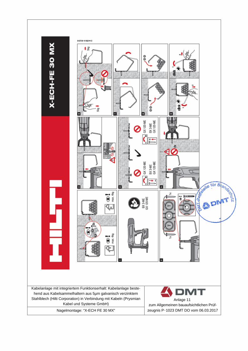
Kabelanlage mit integriertem Funktionserhalt: Kabelanlage beste-hend aus Kabelsammelhaltern aus 5µm galvanisch verzinktem
Stahlblech (Hilti Corporation) in Verbindung mit Kabeln (Prysmian Kabel und Systeme GmbH)
Anlage 11
zum Allgemeinen bauaufsichtlichen Prüf-zeugnis P‑1023 DMT DO vom 06.03.2017 Nagelmontage: “X-ECH FE 30 MX”
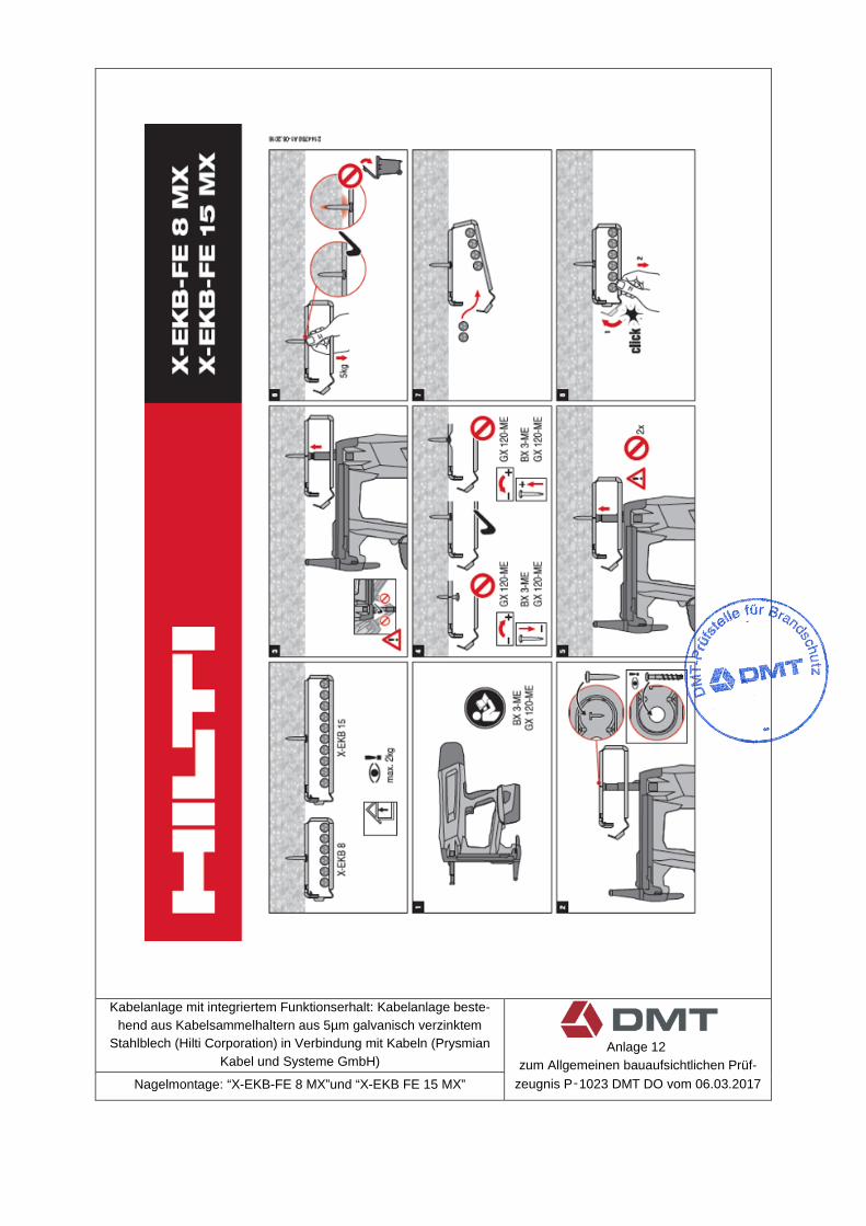
Kabelanlage mit integriertem Funktionserhalt: Kabelanlage beste-hend aus Kabelsammelhaltern aus 5µm galvanisch verzinktem
Stahlblech (Hilti Corporation) in Verbindung mit Kabeln (Prysmian Kabel und Systeme GmbH)
Anlage 12
zum Allgemeinen bauaufsichtlichen Prüf-zeugnis P‑1023 DMT DO vom 06.03.2017 Nagelmontage: “X-EKB-FE 8 MX”und “X-EKB FE 15 MX”

Kabelanlage mit integriertem Funktionserhalt: Kabelanlage beste-
hend aus Kabelsammelhaltern aus 5µm galvanisch verzinktem Stahlblech (Hilti Corporation) in Verbindung mit Kabeln (Prysmian
Kabel und Systeme GmbH)
Anlage 13
zum Allgemeinen bauaufsichtlichen Prüf-zeugnis P‑1023 DMT DO vom 06.03.2017 Nagelmontage: Setzgeräte und Nägel