Embed Size (px)
Citation preview

TO THE OWNER
Congratulations! We welcome you to the exciting world of motor home travel and camping. You will find it convenient and enjoyable to have all the comforts of home and still enjoy the great outdoors wher-ever you choose to go.
Your motor home has been carefully designed, engineered and manufactured to provide dependability as well as safety. Before sliding into the driver’s seat, take a few minutes to become familiar with opera-tions and features. This manual was prepared to aid you in the proper care and operation of the vehicle and equipment. We urge you to read it completely. In addition, spend some time with the dealer when you take delivery, you will want to learn all you can about your new motor home.
Your new motor home is covered by a factory warranty against defects in material and workmanship. This warranty should be validated at once and returned to the factory by your dealer.
Read and understand all instructions and precautions in this manual before operating your new motor home. Throughout this manual, certain items are labeled NOTE, CAUTION and WARNING. These terms alert you to precautions that can involve risk to your vehicle or to your personal safety. Read and follow them carefully.
NOTE: Indicates a special point of information.
.
CAUTIONIndicates that a failure to observe can cause damage to vehicle or equip-ment
WARNINGThis symbol is used to alert you to precautions that involve your per-sonal safety as well as vehicle dam-age. Read and follow them carefully.
054185-J2-000July 1998

*LP Gas tank capacity shown is the usable “full” LP gas capacity, which is 80% of the tank manufacturer’s listed water capac-ity (w.c. shown in parenthesis). An LP tank must have at least 20% of tank volume free to allow for expansion and propervaporization of the liquid fuel. The tank is also equipped with mandatory safety shut-off equipment that prevents filling abovethis level.
OWNER’S NAMESTREET ADDRESSCITY AND STATE (OR PROVINCE IN CANADA)MOTOR HOME SERIAL NUMBERVEHICLE CHASSIS IDENTIFICATION NO. (VIN)DATE OF DELIVERY TO FIRST RETAIL PURCHASERVEHICLE MILEAGE AT TIME OF DELIVERYSELLING DEALER NAME AND ADDRESS
TANK CAPACITIESChassis Fuel TankChevy chassis ................................................................................................................... 75 gal.Ford chassis ....................................................................................................................... 75 gal.Freightliner diesel chassis .................................................................................................. 90 gal.
LP Gas TankModels 33B, 34Y, 35C, 35U & 36L (Chevy/Ford chassis) ........................ 23 gal.* (28 gal. w.c.)Model 36L (Freightliner chassis)................................................................ 31 gal.* (39 gal. w.c.)
Fresh Water TankModel 33B .......................................................................................................................... 70 gal.Model 36L (Freightliner chassis)........................................................................................ 86 gal.Models 34Y, 35C, 35U & 36L (Chevy/Ford chassis)......................................................... 92 gal.
Water Heater - All Models ................................................................................................. 6 gal.
HT1 - Black Water Holding TankModels 33B, 34Y & 36L (Toilet) ....................................................................................... 55 gal.Models 35C & 35U (Toilet)................................................................................................ 40 gal.
HT2 - Gray Water Holding TankModels 33B, 34Y & 36L (Galley, Shower & Lavatory) .................................................... 55 gal.Models 35C & 35U (Galley, Shower & Lavatory)......................................................... TBD gal.

TABLE OF CONTENTS
INTRODUCTIONAbout This Manual ............................... 0-1Chassis Operating Guide ...................... 0-1Before Driving ...................................... 0-1Owner’s InfoCase ................................. 0-1Options and Equipment ........................ 0-2Before Driving ...................................... 0-2Service Assistance ................................ 0-2Warranty................................................ 0-2Drinking and Driving............................ 0-2Reporting Safety Defects ...................... 0-2Vehicle Certification Label ................... 0-4Exterior Feature Identification.............. 0-5
SECTION 1: SAFETY PRECAUTIONSGeneral Warnings.................................. 1-1Driving .................................................. 1-1Fuel & LP Gas ...................................... 1-2LP Gas Leaks ....................................... 1-2LP Gas Alarm ....................................... 1-3Electrical ............................................... 1-4Loading ................................................. 1-4Maintenance.......................................... 1-4Formaldehyde Warning......................... 1-5Carbon Monoxide Warning................... 1-5Carbon Monoxide Alarm ...................... 1-5Emergency Exit Window ...................... 1-6Fire Extinguisher................................... 1-7Smoke Alarm ........................................ 1-7
SECTION 2: DRIVING YOUR MOTOR HOME
Before Entering..................................... 2-1Before Driving ...................................... 2-1Fuel Information ................................... 2-2Fuel Tank Fill ........................................ 2-2Fuel Tank Capacity ............................... 2-2Starting and Stopping Engine ............... 2-3Engine Block Heater (Freightliner) ...... 2-4Parking Brakes ...................................... 2-4Engine Exhaust Brake (Freightliner) .... 2-5Door Locks and Handles....................... 2-6“Key One” Lock System....................... 2-6Entrance Step ........................................ 2-6Luggage Compartment Doors............... 2-7Seats ...................................................... 2-7Seat Belts .............................................. 2-8
Three-Point Lap Shoulder Belt ............. 2-9Child Restraints................................... 2-10Power Mirrors ..................................... 2-11Sony Rearview Monitor System......... 2-11Instrument Panel ................................. 2-12Cruise Control .................................... 2-14Comfort Controls ................................ 2-14
Heating............................................. 2-15Defrosting ........................................ 2-15Ventilation........................................ 2-15Air Conditioning .............................. 2-15Rear Auto Heater ............................. 2-15
Stereo Sound Systems......................... 2-16Radio/Cassette Player ......................... 2-16Radio Power Switch............................ 2-16Deluxe Sound System......................... 2-16Compact Disc Changer ....................... 2-16Auxiliary Start Switch......................... 2-16Auxiliary Battery Switch .................... 2-17CB Radio Wiring ................................ 2-17Coach Leveling Systems..................... 2-18Jet Air Ride Park & Level System...... 2-18Slideout Room .................................... 2-20
Travel Latches.................................. 2-20Extending ......................................... 2-20Retracting......................................... 2-21Emergency Crank-In........................ 2-21
SECTION 3: IN CASE OF DRIVING EMERGENCY
Hazard Flashers..................................... 3-1Spare Tire.............................................. 3-1Tire Changing
Safety Precautions.............................. 3-2Front Wheel ....................................... 3-2Dual Rear Wheels .............................. 3-3Wheel Nuts ........................................ 3-3
Recovery Towing.................................. 3-3Jump Starting ........................................ 3-4Connecting a Battery Charger............... 3-4Engine Overheat ................................... 3-5
SECTION 4: TRAVELING WITH YOUR MOTOR HOME
Loading the Vehicle .............................. 4-1Front Axle Tire Alignment ................... 4-1Weighing Your Loaded Vehicle ............ 4-1

TABLE OF CONTENTS
Maximum Occupancy........................... 4-2Roof Loading ........................................ 4-2Car or Trailer Towing ........................... 4-2Pre-Travel Checklist ............................. 4-3Travel Tips ............................................ 4-3Severe Weather Information ................. 4-4Nighttime Driving................................. 4-5Mountain Driving ................................. 4-5Campsite Selection ............................... 4-6Leveling ................................................ 4-6Blocking................................................ 4-6Effects of Prolonged Occupancy .......... 4-7Humidity and Condensation ................. 4-7
SECTION 5: LP GAS SYSTEMLP Gas Supply ..................................... 5-1Safe Use of LP Gas System .................. 5-1How LP Gas Works .............................. 5-1Selecting Fuel Types ............................. 5-2LP Tank System .................................... 5-2Refilling Tank ....................................... 5-3Air in the LP Gas Tank ......................... 5-3Traveling with LP Gas .......................... 5-3Regulator............................................... 5-4LP Gas Leaks ........................................ 5-5Winter Use of LP Gas ........................... 5-5
SECTION 6: ELECTRICAL SYSTEMS110-Volt AC System ............................. 6-1External Power Cord (Shoreline).......... 6-1Connecting the Shoreline...................... 6-2PowerLine Energy Management
System................................................ 6-2110-Volt Circuit Breakers ..................... 6-3Power Converter System .................... 6-3Charging Section................................... 6-4Overload Protector ................................ 6-4Inverter/Charger, 1500W - Optional ..... 6-4110-Volt Receptacles (Outlets) ............. 6-4Ground Fault Circuit Interrupter
(GFCI)................................................ 6-4Auxiliary 110-Volt Generator
Operating Instructions........................ 6-512-Volt DC System ............................... 6-7Automotive (Starting) Battery .............. 6-7Coach Battery ....................................... 6-7Solar Charger Panel .............................. 6-8Battery Access (Storage)....................... 6-9Battery Maintenance ............................. 6-9Trailer Wiring Connector .................... 6-10
SECTION 7: PLUMBING SYSTEMSFresh Water System .............................. 7-1Filling Water Tank ................................ 7-1Fresh Water Tank Capacity ................... 7-1Water Pump........................................... 7-2Water Pump Switch............................... 7-2Accumulator Tank................................. 7-2External (City Water) Connector .......... 7-3Disinfection of Water Tank................... 7-3Water Purifier System........................... 7-4Shower Hose Vaccum Breaker ............. 7-4Exterior Shower .................................... 7-5Drainage System (Waste)...................... 7-5Dumping Holding Tanks....................... 7-5Flushing Black Water Tank................... 7-6Using On-Site Sewer Hook-Ups........... 7-6Water Drain Valves ............................... 7-7Holding Tank Capacities....................... 7-7Water System Drain Valve
Locations............................................ 7-8SECTION 8: APPLIANCES AND INTERIOR FEATURES
Refrigerators .................................8-1 - 8-5Range and Oven.................................... 8-5Microwave Oven................................... 8-6Range Hood and Monitor Panel............ 8-6Tank Level Checking ............................ 8-7Water Heater ......................................... 8-7By-Pass Valve ....................................... 8-8Motor Aid Water Heater ....................... 8-9LP Gas Furnace..................................... 8-9Central Air Conditioner ...................... 8-10TV Antenna......................................... 8-10TV Signal Amplifier ........................... 8-11Phone & Cable TV Hook-Up ............. 8-12Video Control Center .......................... 8-12Satellite TV System - Optional ........... 8-12DC-AC Electrical Voltage Inverter ..... 8-13Exterior Entertainment Center ........... 8-13Sleeping Facilities
Couch/Bed Conversion .................... 8-13Dinette/Bed Conversion................... 8-14
Fresh Water Toilet............................... 8-14Power Roof Vent ................................ 8-15Crank-Out Windows ........................... 8-15Slider Windows................................... 8-15Day/Night Pleated Shades .................. 8-15

TABLE OF CONTENTS
SECTION 9: CARE AND MAINTENANCERoof ...................................................... 9-1Underbody ............................................ 9-1Exterior ................................................. 9-1
Waxing and Polishing ........................ 9-1Stripes and Decals, care of.................... 9-2Compartment Doors.............................. 9-2Interior Maintenance
Upholstery, Carpeting and Draperies ........................................ 9-2Cabinets ............................................. 9-3Vinyl Wallboard ................................. 9-3Tables and Countertops...................... 9-3Stainless Steel Sink ............................ 9-3Bathroom ........................................... 9-4Doors and Windows........................... 9-4
Vehicle Maintenance Chassis Service and Maintenance...... 9-4Engine Access.................................... 9-4Fuel/Water Separator, Diesel ............. 9-5Engine Cooling System ..................... 9-6Tires ................................................... 9-6Suspension Alignment and Tire Balance............................................ 9-6Windshield Washers and Wipers........ 9-6Lights ................................................. 9-6Automotive 12-Volt Circuit Breakers ............................ 9-7
SECTION 10: STORING YOUR MOTOR HOME
Preparing Vehicle for Storage ............. 10-1Cold Weather Storage
(Winterizing)...........................10-1, 10-3RV Antifreeze Winterization Systems ........................................... 10-4Remove from Storage ......................... 10-5


INTRODUCTION
0-1
Congratulations on the purchase of your new Chieftain motor home, which has been carefully designed, engineered and quality built by Winnebago Industries, Inc.
ABOUT THIS MANUAL
Please read this operator’s manual complete-ly to understand how everything in your coach works before taking it on its “maiden voyage.”
This manual is a quide to safe operation of the features, equipment and controls in this coach. Some equipment, such as the vehicle chassis and certain electronic systems or appliances, have their own comprehensive, manufacturer supplied manuals or information sheets which describe operation of these products in great detail. This manual will refer you to the manufacturer’s in-formation included in your Owner INFOCASE whenever necessary.
SUBJECT ICONS - To make it easier for you to find information you’re looking for, we have placed convenient, pictorial symbols called “icons” beside many of the subject headings in this manual. The icons correspond to the subject matter of the section. These icons were designed similar to the familiar international symbols which identify public facilities such as restrooms and handicap access. There are several examples of icons on this page.
PAGE ICONS - The icons at the upper cor-ners of each page correspond to the primary con-tent of each main section of the manual, such as LP Gas, Electrical, Plumbing, etc. This means you can flip through the manual either forward or backward and know exactly which main section you are looking for just by watching the icons at the top of the page. This means less paging back and forth.
We also urge you to read the complete Chassis Operating Guide provided by the chassis maker and all other operating infor-mation provided by our equipment suppliers and manufacturers. This is contained in your Owner INFOCASETM.
This manual should be kept in the vehicle at all times for personal reference. The operator’s manual, INFOCASE and chassis operating guide are to be considered permanent components of this vehicle. They should remain in the vehicle when sold to provide the next owner with impor-tant safety, operating and maintenance informa-tion.
NOTE: The descriptions, illustrations, and spec-ifications in this manual were correct at the time of printing. We reserve the right to change specifications or design with-out notice, and without incurring obliga-tion to install the same on products previously manufactured.
CHASSIS OPERATING GUIDE
Throughout this manual, frequent reference is made to the vehicle chassis operating guide. The chassis guide is the operator’s manual pro-vided by the manufacturer of the chassis on which this motor home is built (i.e., Chevrolet, Ford, Freightliner, etc.). Consult the chassis guide for operating safety and maintenance in-structions pertaining to the chassis section of the motor home.
OWNER’S INFOCASE
Your Owner’s InfoCase contains information supplied by manufacturers of individual appli-ances and equipment installed in your motor home.
Consult this information regarding the opera-tion and care of appliances, accessories and spe-cial equipment.

INTRODUCTION
0-2
OPTIONS AND EQUIPMENTThis model is available in several sizes and
floorplans, so accessories and components may differ slightly between models. Some equipment described in this manual may not apply to your coach.
BEFORE DRIVINGBefore sitting in the driver’s seat, al-ways check around your vehicle to be
sure you have proper clearance for maneuvering. If necessary, have a passenger help guide you out of a difficult parking space.
Although your coach features automotive conveniences like power steering and power brakes, driving a motor home is different from driving a car. A motor home is larger and heavier than an automobile, so it requires more stopping and passing distance, and more parking and ma-neuvering space than a car does.
Always be mindful of the size of your motor home. The added height of roof air conditioners, TV antennas or luggage boxes may cause clear-ance problems around some tunnels, canopies and hanging signs. Know the height of your unit so you can observe posted clearance limits. Also, remember that some bridges, old ones in particu-lar, may not support the weight of your motor home. Know the weight of your unit and observe any posted weight limits.
Remember: Always use your seat belt and be sure your passengers do so as well. We also ad-vise making frequent rest stops while traveling to relieve stress on yourself, your passengers and your vehicle.
SERVICE AND ASSISTANCE
Your dealer will be glad to provide any addi-tional information you need, as well as answer any questions you might have about operating the equipment in your motor home. When it comes to service, remember that your dealer knows your vehicle best and is interested in your satisfaction. Your dealer will provide quality maintenance
and any other assistance that you may require during your ownership of this vehicle.
If you need warranty repairs while traveling, however, you may take your motor home to any Winnebago or Itasca dealership and they will as-sist you.
WARRANTY
Your new vehicle is covered by a factory warranty against defects in material and work-manship. This warranty should be validated im-mediately and returned to the factory by your dealer. For additional information, see your “New Vehicle Limited Warranty” included with this vehicle.
DRINKING AND DRIVING
Winnebago Industries supports the recom-mendations of the Presidential Commission on Drunk Driving.
� Exercise your good judgment and encourage others to do the same.
� Know the legal limits and do not exceed them.
� Also know your personal limits, which may be lower than the legal limits.
� Should you ever exceed your limits, find al-ternative transportation; call a cab, ask a friend to drive you home or call a family member to come and get you.
The presence of alcohol in significant levels in the blood increases the probability that the driver will be involved in an accident.
REPORTING SAFETY DEFECTSIf you believe that your vehicle has a defect
which could cause a crash or could cause injury or death, you should immediately inform the Na-tional Highway Traffic Safety Administration (NHTSA) in addition to notifying Winnebago In-

0-3
INTRODUCTION
dustries, Inc.If NHTSA receives similar complaints, it
may open an investigation, and if it finds that a safety defect exists in a group of vehicles, it may order a recall and remedy campaign. However, NHTSA cannot become involved in individual problems between you, your dealer, or Winneba-go Industries.
To contact NHTSA, you may either call the Auto Safety Hotline toll-free at 1-800-424-9393 (or 366-0123 in Washington, D.C. area) or write to: NHTSA, U.S. Department of Transportation, Washington, D.C. 20590. You can also obtain other information about motor vehicle safety from the Hotline.
INTRODUCTION
0-4
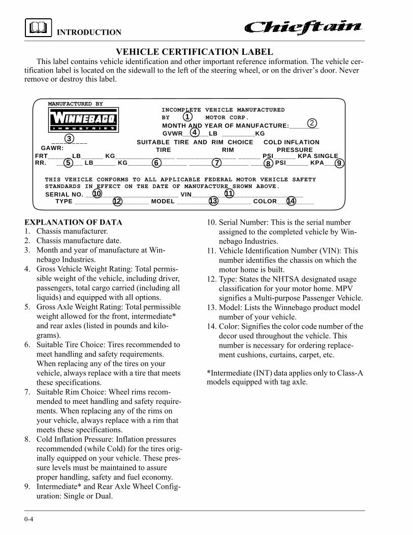
VEHICLE CERTIFICATION LABELThis label contains vehicle identification and other important reference information. The vehicle cer-
tification label is located on the sidewall to the left of the steering wheel, or on the driver’s door. Never remove or destroy this label.
EXPLANATION OF DATA1. Chassis manufacturer.2. Chassis manufacture date.3. Month and year of manufacture at Win-
nebago Industries.4. Gross Vehicle Weight Rating: Total permis-
sible weight of the vehicle, including driver, passengers, total cargo carried (including all liquids) and equipped with all options.
5. Gross Axle Weight Rating: Total permissible weight allowed for the front, intermediate* and rear axles (listed in pounds and kilo-grams).
6. Suitable Tire Choice: Tires recommended to meet handling and safety requirements. When replacing any of the tires on your vehicle, always replace with a tire that meets these specifications.
7. Suitable Rim Choice: Wheel rims recom-mended to meet handling and safety require-ments. When replacing any of the rims on your vehicle, always replace with a rim that meets these specifications.
8. Cold Inflation Pressure: Inflation pressures recommended (while Cold) for the tires orig-inally equipped on your vehicle. These pres-sure levels must be maintained to assure proper handling, safety and fuel economy.
9. Intermediate* and Rear Axle Wheel Config-uration: Single or Dual.
10. Serial Number: This is the serial number assigned to the completed vehicle by Win-nebago Industries.
11. Vehicle Identification Number (VIN): This number identifies the chassis on which the motor home is built.
12. Type: States the NHTSA designated usage classification for your motor home. MPV signifies a Multi-purpose Passenger Vehicle.
13. Model: Lists the Winnebago product model number of your vehicle.
14. Color: Signifies the color code number of the decor used throughout the vehicle. This number is necessary for ordering replace-ment cushions, curtains, carpet, etc.
*Intermediate (INT) data applies only to Class-A models equipped with tag axle.
MANUFACTURED BYINCOMPLETE VEHICLE MANUFACTUREDBY MOTOR CORP.
MONTH AND YEAR OF MANUFACTURE:________GVWR_______LB _________KG
SUITABLE TIRE AND RIM CHOICE COLD INFLATIONTIRE RIM PRESSUREGAWR:
FRT______ LB______ KG________________ ________________ ______ PSI______ KPA SINGLERR. _______ LB______ KG________________ ________________ ______ PSI______ KPA______
THIS VEHICLE CONFORMS TO ALL APPLICABLE FEDERAL MOTOR VEHICLE SAFETYSTANDARDS IN EFFECT ON THE DATE OF MANUFACTURE SHOWN ABOVE.
SERIAL NO. _________________________ VIN______________________________ TYPE ____________________ MODEL ____________________ COLOR__________
5
1
34
6 7 8 9
1012
1113 14
2
0-5
INTRODUCTION
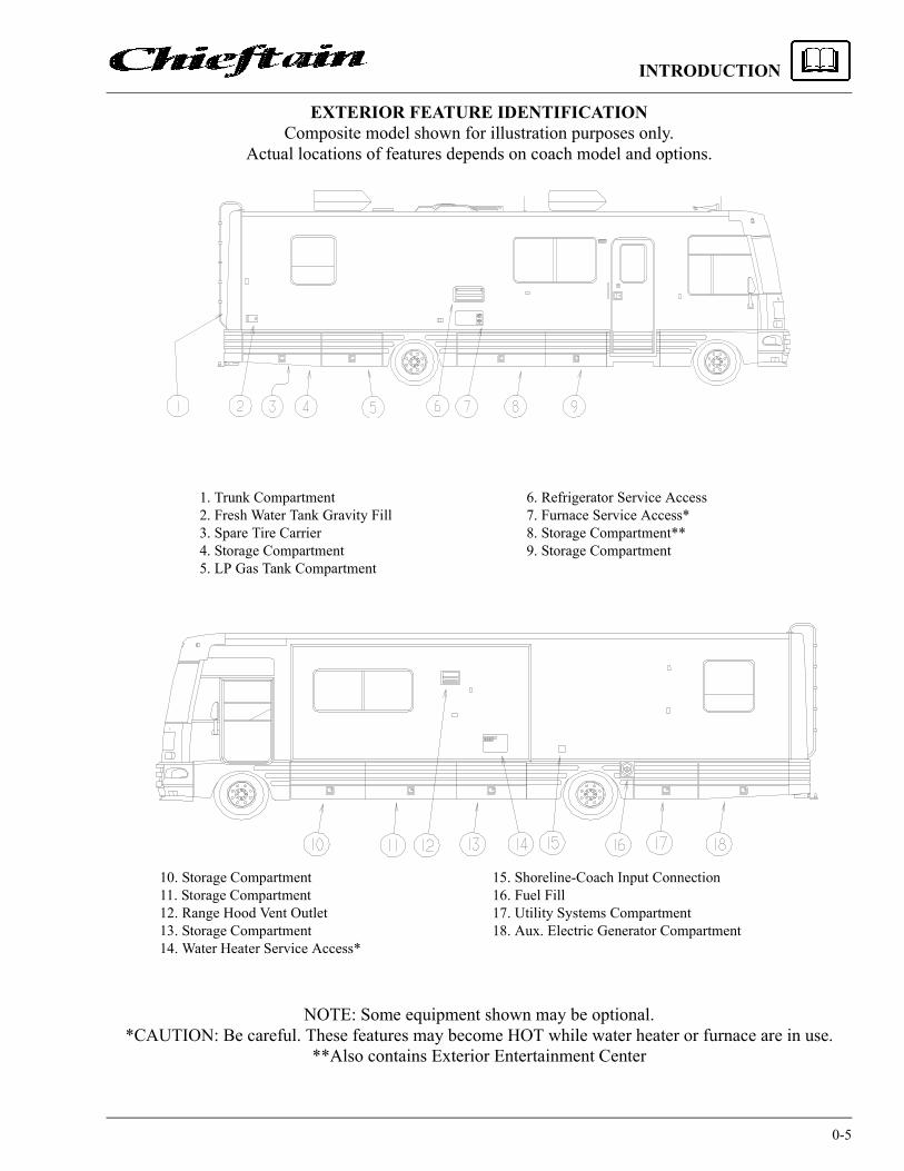
EXTERIOR FEATURE IDENTIFICATIONComposite model shown for illustration purposes only.
Actual locations of features depends on coach model and options.
NOTE: Some equipment shown may be optional.*CAUTION: Be careful. These features may become HOT while water heater or furnace are in use.
**Also contains Exterior Entertainment Center
10. Storage Compartment11. Storage Compartment12. Range Hood Vent Outlet13. Storage Compartment14. Water Heater Service Access*
15. Shoreline-Coach Input Connection16. Fuel Fill17. Utility Systems Compartment18. Aux. Electric Generator Compartment
6. Refrigerator Service Access 7. Furnace Service Access* 8. Storage Compartment** 9. Storage Compartment
1. Trunk Compartment2. Fresh Water Tank Gravity Fill3. Spare Tire Carrier4. Storage Compartment5. LP Gas Tank Compartment


SECTION 1SAFETY PRECAUTIONS
1-1
Read and understand all instructions and pre-cautions in this manual before operating your new motor home. Throughout this manual, cer-tain items are labeled NOTE, CAUTION and WARNING. These terms alert you to precautions that can involve risk to your vehicle or to your personal safety. Read and follow them carefully.
NOTE: Indicates special point of information.
Listed below are some safety precautions that must be adhered to. These precautions as well as others that involve damage to equipment are also listed in the appropriate areas in this manual.
GENERAL WARNINGS
� Only seats equipped with seat belts are to be occupied while the vehicle is moving.
� Make sure all passengers have seat belts fas-tened in a low and snug position so the force exerted by the belt in a collision will be spread across the strong hip area. Pregnant women should wear a lap-shoulder belt whenever possible, with the lap belt portion worn low and snug throughout the pregnan-cy.
� All moveable or swiveling seats should be placed and locked in forward facing positions while the vehicle is moving.
� Never let passengers stand or kneel on seats while the vehicle is moving.
� Sleeping facilities are not to be utilized while vehicle is moving.
� Examine the escape window and be familiar with its operation, but do not use except in an emergency.
• �nspect the fire extinguisher monthly for proper charge and operating condition. This should also be done before beginning a vaca-tion or any extended trip.
DRIVING
� Do not attempt to adjust the driver’s seat while the vehicle is moving.
� Do not adjust tilt steering in a moving vehicle.
� Do not operate the cruise control on icy or extremely wet roads, winding roads, in heavy traffic, or in any other traffic situation where a constant speed cannot be maintained.
� Use care when accelerating or decelerating on a slippery surface. Abrupt speed changes can cause skidding and loss of control.
� Driving through water deep enough to wet the brakes may affect stopping distance or cause the vehicle to pull to one side. Check brake operation in a safe area to be sure they have not been affected. Never operate any vehicle if a difference in braking efficiency is noticeable.
CAUTIONIndicates that a failure to observe can cause damage to vehicle or equip-ment
WARNINGThis symbol is used to alert you to precautions that involve your per-sonal safety as well as vehicle dam-age. Read and follow them carefully.
SECTION 1SAFETY PRECAUTIONS
1-2
� Adverse weather conditions and extremes in terrain may affect handling and/or perfor-mance of your vehicle. Refer to your chassis manual for related information.
FUEL & LP GAS
� All pilot lights must be extinguished and ap-pliances turned off while refilling the fuel tank or LP tank.
� Never smoke while refilling vehicle fuel tank or LP gas tank.
� Avoid inhaling exhaust gases produced by burned gasoline, diesel fuel or LP gas in items such as the range, chassis engine, gen-erator engine, refrigerator, furnace and water heater. They contain carbon monoxide, which is an odorless, colorless and poisonous gas.
� Do not bring or store LP gas containers, gas-oline or other flammable liquids inside the vehicle because a fire or explosion may re-sult. LP gas containers are equipped with safety valves which relieve excessive pres-sure by discharging gas to the atmosphere.
� Do not fill LP gas container(s) above 80 per-cent of capacity. Overfilling the LP gas con-tainer can result in uncontrolled gas flow which can cause fire or explosion. A properly filled container will contain approximately 80 percent of its volume as liquid LP gas.
� Never use an open flame to test for LP gas leaks. Replace all protective covers and caps on LP system after filling. Make sure valve is closed and door latched securely.
� Never connect natural gas to the LP gas sys-tem.
� When lighting range burners do not turn burner controls to “On” and allow gas to es-cape before lighting match.
� Portable fuel-burning equipment, including wood and charcoal grills and stoves, shall not be used inside the recreational vehicle. The use of this equipment inside the recreational vehicle may cause fires or asphyxiation.
� LP gas regulators must always be installed with the diaphragm vent facing downward. Regulators are equipped with a protective cover. Make sure that the regulator vent faces downward and that the cover is kept in place to minimize vent blockage which could result in excessive gas pressure causing fire or ex-plosion.
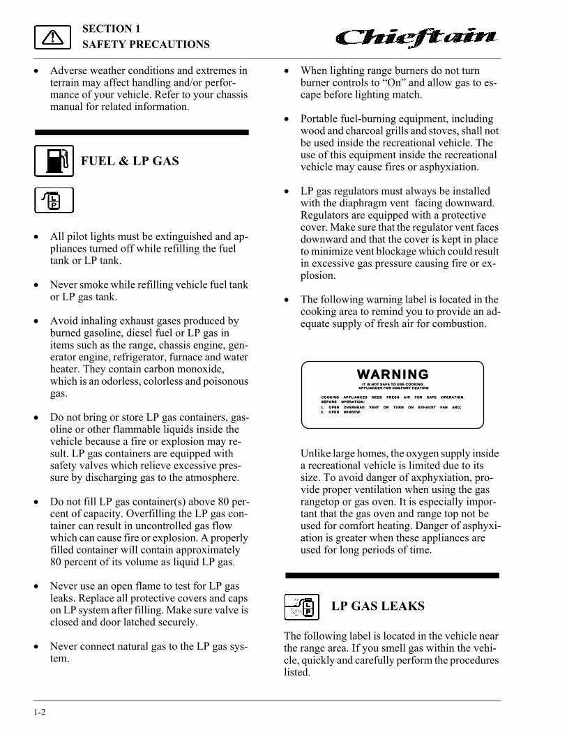
� The following warning label is located in the cooking area to remind you to provide an ad-equate supply of fresh air for combustion.
Unlike large homes, the oxygen supply inside a recreational vehicle is limited due to its size. To avoid danger of axphyxiation, pro-vide proper ventilation when using the gas rangetop or gas oven. It is especially impor-tant that the gas oven and range top not be used for comfort heating. Danger of asphyxi-ation is greater when these appliances are used for long periods of time.
LP GAS LEAKS
The following label is located in the vehicle near the range area. If you smell gas within the vehi-cle, quickly and carefully perform the procedures listed.
WARNING IT IS NOT SAFE TO USE COOKING I T IS NOT SAFE TO USE COOKINGAPPL IANCES FOR COMFORT HEAT INGAPPL IANCES FOR COMFORT HEAT ING
COOKING APPL IANCES NEED FRESH A IR FOR SAFE OPERAT ION.COOKING APPL IANCES NEED FRESH A IR FOR SAFE OPERAT ION.
BEFORE OPERAT ION:BEFORE OPERAT ION:
1 . OPEN OVERHEAD VENT OR TURN ON EXHAUST FAN AND;1 . OPEN OVERHEAD VENT OR TURN ON EXHAUST FAN AND;
2 . OPEN WINDOW.2 . OPEN WINDOW.

1-3
SECTION 1SAFETY PRECAUTIONS
LP GAS ALARM
Your coach is equipped with an LP gas detec-tor which sounds an alarm if an unsafe amount of LP gas is present inside the coach. Because LP gas is heavier than air, the detector is located on a cabinet face near the floor of the coach.
A green light on the face of the alarm shows when the unit is active. If the detector senses LP gas, the alarm will make a loud, pulsating sound and the red light will come on. Pressing the “MUTE” button will stop the alarm for 60 sec-onds. If there is no more detectable LP gas, the alarm will stay off. If the detector still senses LP gas by the end of the 60 second mute mode, the alarm will sound again.
If The Alarm SoundsIf the alarm sounds, do not touch any electrical
switches. Immediately turn off the main LP tank valve and all LP appliances, open all windows and roof vents, and leave the coach until the alarm stops sounding.
If the alarm keeps sounding at regular inter-vals, a leak may be present. Contact your dealer or an LP gas service center to have the problem corrected before using the LP system again.
Power ConnectionThe gas alarm is powered by the coach batter-
ies. If the battery cable is disconnected from the batteries, auxiliary battery switch is shut off, or the fuse is blown, the alarm will not work. The LP gas alarm breaker is located on the coach cir-cuit breaker panel shown on page 6-7.
Because the LP gas alarm is connected direct-ly to the auxiliary battery, it is always drawing a small amount of current. Even though this current draw is slight, it could drain the coach battery during storage periods of 30 days or longer. We recommend turning the auxiliary battery switch off or disconnecting the battery cables from the auxiliary battery during extended storage periods to avoid discharge.
IF YOU SMELL GAS1. Extinguish any open flames, pilot
lights and all smoking materials.2. Do not touch electrical switches.3. Shut off the gas supply at the tank
valve(s) or gas supply connection.4. Open doors and other ventilating
openings.5. Leave the area until odor clears.6. Have the gas system checked and
leakage source corrected before using again.
WARNINGNever use an open flame to test for gas leaks. When testing for gas line leaks with a soapy water solution, DO NOT use a detergent containing ammonia or chlorine. These sub-stances may generate a chemical reaction causing corrosion to gas lines, resulting in dangerous leak con-ditions.

SECTION 1SAFETY PRECAUTIONS
1-4
If the coach batteries become extremely drained (8.5 volts or less), the amber Low Volt-age/FAULT light on the face of the alarm will cone on, and in some rare cases the LP alarm may begin to sound on its own. This condition is not likely to occur except during storage situations when coach battery charge is not being restored by the converter charger or solar charger.
Other Combustible Fumes or VaporsThis alarm is designed to detect the presence
of LP gas, however there are other combustible fumes or vapors which may be detected by the sensor. These include: alcohol, liquor, deodor-ants, colognes, perfumes, wine, adhesives, lac-quer, kerosene, gasoline, glues, most all cleaning agents and the area is closed up. Glues and adhe-sives may exhaust hydrocarbon vapors for months after they are applied. They are easily ac-tivated by high temperatures. If you close up an RV coach on a hot day, the chemicals used in its construction may be detected for months after the coach was manufactured.
Further InformationSee the manufacturer’s information entitled
“Your LP Gas Detector” in the InfoCase for fur-ther instructions on nuisance alarms and care and testing of the LP gas detector.
ELECTRICAL
� Careless handling of electrical components can be fatal. Never touch or use electrical components or appliances while feet are bare, while hands are wet, or while standing in water or on wet ground.
� Improper grounding of the vehicle can cause personal injury. Do not plug the utility power cord into an outlet which is not grounded and do not adapt the plug to connect to a recepta-cle for which it is not designed.
� Do not attach an extension cord to the utility power cord.
� Be sure that all electrical appliances to be
used contain 3-prong plugs for proper grounding.
� Avoid overloading electrical circuits. Re-place fuses or circuit breakers with those of the same size and amperage rating only. Nev-er use a higher rated fuse or breaker.
� Use caution when handling or working near electrical storage batteries. Always remove jewelry and wear protective clothing and eye covering. Avoid creating sparks.
LOADING
� Store or secure all loose items inside the motor home before traveling.
� Be aware of GVWR, GAWR and individual load limit on each tire or set of duals. (See “Loading the Motor Home” in Section 4.)
� Never load the motor home in excess of the gross vehicle weight rating or the gross axle weight rating for either axle.
MAINTENANCE
� Do not remove the radiator cap while engine and radiator are still hot. Always check cool-ant level visually at the see-through coolant reservoir.
� Never get beneath a vehicle that is held up by a jack.
� Do not mix different construction types of tires on the vehicle such as radial, bias or belt-ed tires, as vehicle handling may be affected. Replace tires with exact size, type and load range.
� Do not attempt to start the vehicle by hot wiring.

1-5
SECTION 1SAFETY PRECAUTIONS
FORMALDEHYDE INFORMATION
IMPORTANTTo aid in dissipation, ventilate the vehicle by opening all windows and circulating the air with a fan.
CARBON MONOXIDE WARNING
If your suspect that exhaust fumes are entering the passenger compartment, have the cause deter-mined and corrected as soon as possible. If you must drive under these conditions, drive only with ALL WINDOWS FULLY OPENED.
The best protection against carbon monoxide entry into the vehicle body is a properly main-tained engine exhaust and ventilation system. It is recommended that the exhaust system and body be inspected by a qualified motor home ser-vice center.
� Each time the vehicle is raised for an oil change.
� Whenever a change in the sound of the ex-haust system is noticed.
� Whenever the exhaust system, underbody or rear of the vehicle is damaged.
To allow proper operation of the vehicle’s ventilation system, keep front ventilation inlet grill clear of snow, leaves or other obstructions at all times. DO NOT OCCUPY A PARKED VE-HICLE WITH ENGINE RUNNING FOR AN EXTENDED PERIOD.
Do not run engine in confined areas, such as a garage, except to move vehicle in or out of area. When vehicle is stopped in an UNCONFINED area with the engine running for any more than a short period, adjust heating or cooling system to force outside air into the vehicle as follows:
1. Set fan to medium or high speed and vent control to air.
2. On vehicles equipped with air conditioning, set fan to medium or high speed and set con-trol to obtain maximum vent air.
Rear windows should be closed while driving to avoid drawing dangerous exhaust gases into the vehicle.
CARBON MONOXIDE ALARM
If your coach is equipped with a carbon mon-oxide (CO) alarm, it will be located on the ceiling in the bedroom area.
WARNINGSome components in this vehicle con-tain formaldehyde based adhesives which may release formaldehyde fumes into the air for an unknown period of time until total dissipation occurs. Individuals who are allergic to formaldehyde gas fumes may experience irritation to eyes, ears, nose and throat. Reaction in infants may be more severe. Although long range effects are not well understood, testing to date has not revealed any serious health effects in humans at the level of emission from these prod-ucts.
WARNINGAvoid inhaling exhaust gases, as they contain carbon monoxide, which is a colorless, odorless and poisonous gas.

SECTION 1SAFETY PRECAUTIONS
1-6
The CO alarm is powered by a 9-volt battery and contains a sensor that is designed to detect toxic carbon monoxide gas fumes resulting from incomplete combustion of fuel. It will detect CO gas from any combustion source such as the fur-nace, gas range/oven, water heater, refrigerator, chassis engine, and electric generator engine.
Monthly TestingPress the TEST button on the face of the alarm
periodically (at least monthly) to check the func-tion of the alarm and condition of the battery. If the alarm begins to beep every few seconds, the battery may be weak and need replacement. (Press the TEST button to be sure before replac-ing the battery. If the alarm sounds, the battery may still be okay. If the alarm still beeps every few seconds, check the smoke detector also. The “low battery” warning beep is similar on many alarm devices, so the origin of this electronic sound can be deceiving.)
Further InformationPlease read the information provided by the
manufacturer, which is included in your Info-Case. It includes information on precautions, op-erational testing, and battery/sensor replacement.
EMERGENCY EXITSEmergency Exit Windows
Your motor home is equipped with an emer-gency exit window in the rear or side of the vehi-cle which functions as an escape exit in an emergency situation.
Rear Escape WindowIn rear escape windows, the glass is installed
with a rubber extrusion, it is opened by pulling on the red plastic loop located at the bottom of the window, until the rubber cord in completely re-moved. This allows the window to be pushed out.
Instructions for removal are also located on a label on the glass for quick reference and for pas-sengers who may not be familiar with the exit. Never remove or destroy this label.
If the cord is released by accident, but the glass remains in place, the cord can be replaced using a blunt instrument, preferably one made of plastic. We suggest you contact your dealer for assistance.
Side Escape WindowThe side mounted escape window is secured
by two red safety latches and can be opened by first releasing these two latches and then pushing outward on the lower part of the window. Identi-fy which type of emergency exit window is in your vehicle.
Instructions for removal are also located near the latches for quick reference and for passengers who may not be familiar with the exit. Never re-move or destroy this label.
WARNINGUse emergency window for emer-gency exit only. Do not test for proper operation.
WARNINGUse care when exiting emergency window, as broken glass may be present in the exit area.
RED LOOP

1-7
SECTION 1SAFETY PRECAUTIONS
Using Slider Windows as Emergency Exits
Most single and double slider windows along the side of the motor home can also be used as emergency exits, should the need arise. To use the windows as exits, slide the window glass and screen open.
FIRE EXTINGUISHER
A dry chemical fire extinguisher is located near the floor by the side entrance door.
We recommend that you become thoroughly familiar with the operating instructions displayed on the side of the fire extinguisher or in the infor-mation supplied in your InfoCase.
We also recommend that you inspect the fire extinguisher for proper charge at least once a month in accordance with National Fire Protec-tion Association (NFPA) recommendations as stated on the label.
If the charge is insufficient, the fire extin-guisher must be replaced.
SMOKE ALARM
Your motor home is equipped with a smoke alarm located on the ceiling in the galley area. This alarm meets U.L. Standard 217 and NFPA Standard 74 for operation of smoke detection de-vices.1. The smoke alarm should be tested for correct
operation each time the vehicle is brought out of storage, before each trip, and at least once a week during motor home use. To test the electronics, firmly depress the button. To test that smoke reaches the sensor, blow smoke in a careful, fire-safe manner into your smoke alarm.
2. Your smoke alarm will not work without power. Never remove the battery to quiet the alarm. When your smoke alarm “beeps” about once a minute the battery is weak. Install a new battery immediately. Be sure to use only batteries specified in manual or on unit. Test unit after installing a new battery.
Lift Both Handles UpPush Out on Bottom
WARNINGDo not test the fire extinguisher by discharging it. Partial discharge can cause leakage of pressure or contents which would render the unit inopera-tive when needed. When using the fire extinguisher, aim the spray at the base of the fire.

SECTION 1SAFETY PRECAUTIONS
1-8
3. Clean and vacuum the openings on your smoke alarm once a month.
4. Do not open the smoke alarm or try to repair it. For replacement information see warranty in Owner’s Manual.
5. Smoke alarms have technical limitations and may not respond in all situations. FIRE PRE-VENTION is your best safeguard.
See your InfoCase for further information.
SECTION 2DRIVING YOUR MOTORHOME
2-1
(See also Safety Precautions, Section 1 of thismanual.)
NOTE: See your Chevy, Ford or Freightliner chassis operator's guide for information on starting the engine, operating the transmission, steering column controls descriptions of instrument gauges and other chassis related information.
Some items described in this section may be optional or unavailable on your coach.
BEFORE ENTERING YOUR VEHICLE
Before entering your vehicle, there are a few recommended procedures that will aid in your driving safety and equipment.
1. Be sure that the windows, mirrors and light lenses are clean and unobstructed.
2. Make sure all exterior lights operate prop-erly.
3. Check tires for proper cold inflation pres-sures.
4. Check wheel lug nuts for tightness.5. Look beneath the vehicle for noticeable fluid
leakage.6. Check fluid levels and fill if necessary. This
includes engine oil, transmission fluid, cool-ant, brake fluid, power steering fluid and windshield washer solvent.
7. Unhook and store sewer and water supply hoses.
8. Retract step.9. Be sure that all of your cargo is secured in
event of a sudden stop or an accident.10. Check around your vehicle in all directions
to assure that you have proper clearance.11. Lower TV antenna.12. Disconnect and store shoreline.
BEFORE DRIVING YOUR VEHICLE
Before preparing to drive your vehicle, here are a few recommended procedures that will add to your driving safety and enjoyment.
1. Be sure that you adjust the interior and exte-rior rear view mirrors to your driving prefer-ence.
WARNINGThe engine should be shut off unlessspecifically required for a certain pro-cedure.
Chevy/Ford: Transmission must be in P (Park) and park brake applied while performing any checks or adjust-ments.
Freightliner: The transmission must be in N (Neutral) and park brake applied while performing any checks or adjustments.
WARNINGBefore driving your vehicle, be sureyou have read the entire operator’smanual and that you understand yourvehicle’s equipment completely andhow to use the equipment safely.

SECTION 2DRIVING YOUR MOTOR HOME
2-2
2. Adjust the driver's seat for proper distance from foot pedals and steering wheel to allow for safety and ease in controlling your vehi-cle.
3. Place front seats in the forward facing posi-tion.
4. Be sure to fasten all safety belts to fit you comfortably, but tight enough to obtain the full safety of the belts.
5. Make sure all doors are completely shut and locked. When the doors are shut and locked, there is less chance of the doors flying open in event of an accident. It also prevents unin-tentional opening of doors and keeps intruders out of your vehicle.
6. Check to see that all gauges are operating properly.
7. Check the fuel level in the vehicle.8. Be certain that the fire extinguisher is fully
charged and secure in its mounting bracket.
FUEL INFORMATION
Fuel Tank Capacity:Chevy chassis.........................................75 gal.Ford chassis............................................75 gal.Freightliner diesel chassis ......................90 gal.
FUEL SELECTIONRefer to your chassis operating guide for the
manufacturer's recommendations on proper fuel selection.
GASOLINE FUEL FILL
Removing the Fuel CapWhen removing the gasoline cap, slowly ro-
tate it only far enough to allow pressure to re-lease. After any "hissing" sounds stop, continue removing the cap.
Filling the TankDo not overfill the fuel tank. Allow gasoline
to pump into the tank until the auto-shutoff valve in the fuel pump nozzle stops the flow of fuel, in-dicating a full tank. This provides a pre-deter-mined vapor space at the top of the tank to allow for expansion of the gasoline.
Replacement Fuel CapsTo protect gasoline system from excessive
pressure or vacuum, or from sudden pressure, replace lost caps with caps of the same design available from your Winnebago Industries dealer or a dealership that sells Chevy or Ford vehicles.
STARTING AND STOPPING ENGINE
Refer to your chassis operating guide for the manufacturer's recommendations on starting and stopping the engine.
CAUTIONBe sure hood and all compartment doors are latched securely before driving vehicle
WARNINGModern fuel systems may build uppressure within the tank as the gaso-line warms during use or in hotweather.
Under certain conditions, sudden release of this pressure when removing the gasoline cap can spray gasoline from the fuel fill opening, causing a possible hazard.
CAUTIONContinuing to fill above this level may cause damage to the fuel/evapo-rative emission system.

2-3
SECTION 2DRIVING YOUR MOTOR HOME
Brake-Shift Interlock (Chevy and Ford Chassis)
Chevy and Ford chassis are equipped with a brake-shift interlock safety feature. The shift lever cannot be moved from the Park position unless the ignition is ON and the service brake pedal is pressed.
NOTE: On Ford chassis, if the brake light fuse is blown, the interlock feature will not work properly and an alternate method must be used. See your Ford Owners Guide for detailed instructions on what to do in this situation.
Fuel Pump Shut-Off Switch(Ford Chassis Only)
Vehicles built on Ford chassis are equipped with an inertial type switch that shuts off the fuel pump in the event of collision. This switch must be manually reset to resume the fuel supply to the engine.
See your Ford chassis operating guide for lo-cation and reset procedures for this switch.
NOTE: It is possible to accidentally trigger the fuel pump shut-off switch by abruptly striking an object such as a curb or park-ing block. If your vehicle exhibits symp-toms of running out of fuel immediately after such an occurrence, the fuel pump shut-off switch may need to be reset.Consult your chassis operating guide for additional information.
FUEL SELECTION - FREIGHTLINER DIESEL CHASSIS
Refer to your Freightliner chassis operating guide for the manufacturer's recommendations on proper fuel selection.
Winter Fuel Waxing and Anti-Gel AdditivesIn sub-freezing temperatures, #2 diesel fuel
can form small wax crystals that become trapped in the fuel filter and block the fuel flow to the engine, causing it to stall out. At sub-zero tem-
peratures, the fuel can congeal and turn “slushy”. If this happens, the only remedy is to have the vehicle towed into a heated facility to allow the fuel to warm up and become fully liq-uid again.
During winter time, most truck stops and rep-utable filling stations have winter blend diesel fuels available that are less susceptible to wax-ing.
There are also commercially available prod-ucts, typically called anti-gel additives, to add to diesel fuel while filling the tank to inhibit wax formation in freezing temperatures.
Consult your Freightliner chassis guide or Cummins engine guide for more information on fuel requirements and additives.
Filling the Fuel TankDiesel fuel, especially #2 grade, can foam up
while being pumped into the tank. Sometimes this foam can cause the pump nozzle to shut off before the tank is actually full. Allow the foam to settle then resume filling at a slower flow rate un-til the tank is full.
Fuel Tank Capacity: 90 gals. diesel
STARTING AND STOPPING DIESEL ENGINE
Refer to your Freightliner chassis operating guide for the manufacturer's recommendations on starting and stopping the engine.
See also “Engine Block Heater” in this sec-tion.
Cold Weather Starting: Please note the follow-ing cold weather starting precautions. This label is also located in appropriate areas of the coach. Failure to follow these precautions could cause serious damage to your diesel engine.

SECTION 2DRIVING YOUR MOTOR HOME
2-4
FREIGHTLINER DIESEL ENGINE BLOCK HEATER
Your coach is equipped with an engine block heater to assist starting in freezing temperatures. The heater is connected to both the shoreline and the auxiliary generator, so extension cords are not needed under most circumstances. The power switch is on the bedroom wall on the driver’s side of the coach.
To Use the Engine HeaterWith the shoreline cord plugged into a shore-
line hookup, turn on the engine heater power switch on the bedroom wall on the driver’s side of the coach.
If a shoreline hookup is not available, just start the auxiliary generator to provide power to the engine heater.
REMEMBER! Turn the engine heater switch offafter starting the engine. The heater will keep op-erating for as long as it is supplied with electrici-
ty. If the switch is left on, the engine heater willcome on each time you hook up the shorelinecord or start the generator.
PARKING BRAKESChevy or Ford Chassis:
The parking brake pedal is located to the left of the foot service brake.
To set the parking brake, press the service brake pedal firmly with your right foot while you apply the parking brake with your left foot. The BRAKE warning light will go on as soon as you start to press the parking brake pedal. The brake will not prevent the vehicle from moving unless you push it down firmly and fully. Remove your foot from the service brake pedal and make sure there is no vehicle movement.
To release the parking brake, apply the service brake with your right foot and hold the parking brake pedal down with your left foot while you pull the release lever. The release lever is located above the brake pedal.
NOTE: On some Chevy chassis the parking brakes are applied by pulling outward on the large diamond-shaped knob on the dash to the right of the steering column. Push the knob in to release the parking brakes.
Never drive your vehicle with the parking brake set as this will reduce parking brake effec-tiveness and cause excessive wear.
NOTE: Some Chevy chassis may have parking brakes that are applied by pulling out-ward on a large, diamond-shaped knob on the dash to the right of the steering column. Push the knob in to release the parking brakes.
Optional 16,500 lb. GVWR Chevy Chassis:This chassis is equipped with an automati-
cally applied parking brake that actuates when the shift lever is moved to the Park position.
Diesel Engine Heater Switchon driver side bedroom wall

2-5
SECTION 2DRIVING YOUR MOTOR HOME
Freightliner Diesel Chassis:The parking brakes are applied by pulling out-
ward on the large diamond-shaped knob on the dash to the right of the steering column. Push the knob in to release the brakes.
Use the parking brakes whenever the vehicle is parked. Never try to drive the vehicle with the park brake applied. This can cause excessive wear on the brakes and may damage the transmis-sion.
ENGINE EXHAUST BRAKE Model 36L on Freightliner dieselchassis only
To Use the Exhaust Brake: The switch is lo-cated on the lower left side of the dash.
Press and release the ON side of the switch to activate the exhaust brake system. The ex-haust brake will operate whenever you let up on the throttle while the switch is ON. An indicator light near the switch will glow while the exhaust brake is activated.
Press and release the OFF side of the switch to deactivate the exhaust brake system and return to chassis brakes alone.
How It Works: The Jacobs® Extarder™ is anengine compression retarder that generates“braking” power by controlled restriction of theengine’s exhaust gas flow.
When the exhaust brake is activated, a valve closes off the engine’s exhaust causing the ex-haust back pressure to increase, which causes the vehicle to slow down.
The increased back pressure would normally stop the engine except the forward momentum of the vehicle keeps the drivetrain and the engine turning.
This controlled back pressure helps to regu-late a vehicle’s downhill speed, such as on moun-tainous or hilly roads. It also provides “braking” on level or near-level roads.
For More Information: See the Jacobs® Extarder™ user guide in your InfoCase for complete operating instructions and precautions.
Parking Brake Knob
Exhaust Brake Switch

SECTION 2DRIVING YOUR MOTOR HOME
2-6
ENTRANCE DOOR LOCK AND HANDLE
The entrance door may be opened by pulling the door handle outward. When the door is locked, neither the inside nor the outside door handle can be operated. It can be locked and un-locked from the outside of the vehicle by insert-ing the key into the lock and turning.
To lock the door from inside, rotate the lock levers as indicated. The deadbolt lock is for add-ed security and should be used as a security night lock.
Lubricate the locks periodically with graphite to maintain good working condition.
“KEY ONE” LOCK SYSTEM
Your coach is equipped with the new KeyO-neTM lock system. A single key will open every door lock in the entire motor home (except the se-curity deadbolt lock on the entrance door). This means you don’t have to sort through a handful of keys to find the right one for the water fill door or the luggage doors or the entrance door or the driver’s door.
The number of the key for your coach is reg-istered in our factory database, so if you ever lose your keys, any Winnebago Industries dealership can easily order a new key for you. They are also equipped with special master keys and can un-lock your coach for you if needed.
NOTE: Keys should always be removed when leaving the vehicle. Since doors can be locked without keys, make sure they have been removed from the ignition before locking the driver's compartment.
ENTRANCE STEP - Powered
The electric entrance step will extend auto-matically when you open the entrance door, and retract when you close the door. You can also switch the step power off if you want to keep the step extended while parked at a campsite, when you exit and enter the coach frequently. This saves wear on the step mechanism and conserves coach battery power.
CAUTIONWhen releasing security night lock, be sure to retract bolt before opening door latch to prevent drag on bolt pin. Instruct all passengers in operation of this door catch system as well as emergency exit window.
PULL
Entrance Door Handle - Outside
Secondary
Deadbolt
Door Lock
Entrance Door Handle - Inside
WARNINGDo not use steps unless they are fully extended.
Do Not Stand on electric entrance step when coach engine is being started. The step will automatically retract, which could cause personal injury.

2-7
SECTION 2DRIVING YOUR MOTOR HOME
The step power switch is located on the entry switch panel to the left of the doorway as you en-ter the coach. The step will extend when the door is opened even if the switch is off. The step will not retract, however, unless the switch is on.
If the step will not extend or retract, check the step power switch.
This step has a unique safety retraction feature that prevents damage to the step by driving off with the step extended. Even if the step is extend-ed with the step switch turned off and the en-trance door closed, the step will automatically retract when the coach engine is started.
See the power step owner's manual in your In-foCase for operating instructions and additional information.
LUGGAGE COMPART-MENT DOORS
To ensure that compartment doors have latched properly, press the bottom edge of the door with the palms of your hands.
This is more important for smaller and lighter compartment doors because when the door is “dropped” closed, the air trapped inside the compartment may create a cushioning effect that could prevent door latches from engaging properly.
SEATS
The driver and co-pilot seats may be indepen-dently adjusted to suit individual preference. To move the seat forward or backward, press the slide release button, located on the side of the seat, and exert slight body pressure in the direc-tion desired.
The seats may be swiveled to provide easy en-trance and exit. The swivel feature also allows the seats on some models to be turned toward the living area for additional seating while the unit is parked.
To swivel the seats: Press the release button, located on the side of the seat, and rotate seat. The seats are designed to lock only when re-turned to the forward facing position.
NOTE: If your driver seat is equipped with pow-er seat controls, the swivel release button is located beneath the seat on the right side of the seat.
To recline the seats: Lift the reclining lever, lean back to desired incline and release the lever. To return to the upright position, lift the lever and lean body forward. Allow the seat to return to the desired position and release the lever.
CAUTIONAlways remember to retract the entrance steps before traveling or moving the vehicle.
PORCH STEP CEILING
Entry Switch Panel
SlideRelease
SwivelRelease
ReclineLever

SECTION 2DRIVING YOUR MOTOR HOME
2-8
6-Way Power Seat ControlsThe power seat controls are located on the
lower right hand side of the seat base.
ARM REST ADJUSTMENTThe driver and co-pilot seat armrests may be
adjusted to rest at two different positions as shown.
Position 1 - This is the normal default position ofthe armrest. If the armrest is in position 2, raisearmrest, until it pops outward from the seat, andlower into position. This position would general-ly be used when the seat is in the upright position.
Position 2 - Raise armrest, push inward firmly to-ward seat, and lower into position. You may wishto use this position when you recline the seat.
LOUNGE CHAIRSYour coach may be furnished with one of the
types of swivel/slider lounge chairs shown here. The swivel feature will lock in the center fac-
ing position for your safety while the vehicle is moving.
Swivel: Pull up on the swivel lever located on theside of the seat. The seat will lock into placewhenever it reaches the center aisle facing posi-tion.Always return the seat to the aisle facing positionfor proper use of seat belts while traveling.
Slide: Pull up on the slide lever located on theside of the seat. Slide to desired position and re-lease lever.
SEAT BELTS
Seats intended for occupancy while the vehi-cle is in motion are equipped with seat belts for the protection of the driver and passengers.
WARNINGDo not adjust driver’s seat while vehi-cle is in motion.
After adjusting seat, always use body pressure to make sure slide and swivel locking mechanism have engaged.
Power Seat Control
FrontUp/Down
Main SeatPosition
RearUp/Down
1
2
ReclineSwivel
SlideFootrestLever
2-9
SECTION 2DRIVING YOUR MOTOR HOME
Lap BeltsThe lap belts must be worn as low as possible
and fit snugly across the hip area. Always sit erect and well back into the seat. To gain full pro-tection of the safety belt, never let more than one person use the same safety belt at any one time, and do not let the safety belts become damaged by pinching them in the doors or in the seat mech-anism. After any serious accident, any seat belts which were in use at the time should be replaced.
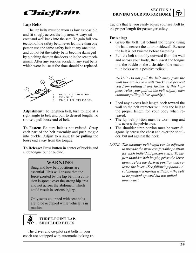
Adjustment: To lengthen belt, turn tongue at aright angle to belt and pull to desired length. Toshorten, pull loose end of belt.
To Fasten: Be sure belt is not twisted. Graspeach part of the belt assembly and push tongueinto buckle. Adjust to a snug fit by pulling theloose end away from the tongue.
To Release: Press button in center of buckle andslide tongue out of buckle.
THREE-POINT LAP-SHOULDER BELTS
The driver and co-pilot seat belts in your coach are equipped with automatic locking re-
tractors that let you easily adjust your seat belt to the proper length for passenger safety.
Fastening:� Grasp the belt just behind the tongue using
the hand nearest the door or sidewall. Be surethe belt is not twisted before fastening.
� Pull the belt smoothly outward from the walland across your body, then insert the tongueinto the buckle on the aisle side of the seat un-til it locks with a positive “click”.
(NOTE: Do not pull the belt away from thewall too quickly or it will “lock” and preventyou from pulling it any farther. If this hap-pens, relax your pull on the belt slightly thencontinue pulling it less quickly.)
� Feed any excess belt length back toward thewall so the belt retractor will lock the belt atthe proper length for your body when re-leased.
� The lap belt portion must be worn snug andlow across the pelvic area.
� The shoulder strap portion must be worn di-agonally across the chest and over the shoul-der, but not against the neck.
NOTE: The shoulder belt height can be adjusted to provide the most comfortable position for each individual person’s size. To ad-just shoulder belt height, press the lever down, select the desired position and re-lease the lever. (See following photo.) A ratcheting mechanism will allow the belt to be pushed upward but not pulled downward.
WARNINGSnug and low belt positions are essential. This will ensure that the force exerted by the lap belt in a colli-sion is spread over the strong hip area and not across the abdomen, which could result in serious injury.
Only seats equipped with seat belts are to be occupied while vehicle is in motion.
1
2
3
1 . PULL TO T IGHTEN.2 . TONGUE.3 . PUSH TO RELEASE.

SECTION 2DRIVING YOUR MOTOR HOME
2-10
� Seat belts offer optimum protection onlywhen worn properly on the body and whenthe seat is in an upright position.
Unfastening:� Press the release button in the buckle.� Hold onto the tongue when you release it
from the buckle to keep it from retracting toorapidly.
Care and Cleaning� Be careful not to damage the belt webbing
and hardware. Take care not to pinch them inthe seat or doors.
� Inspect the belts and hardware periodically.Check for cuts, frays, and loose parts. Dam-aged parts should be replaced. Do not removeor modify the belt system.
� Keep belts clean and dry. If the belts needcleaning, use only a mild soap and water so-lution. Do not use hot water. Do not use abra-
sive cleaners or bleach. These products mayweaken or damage the belts.
� Replace any belt assembly that was used dur-ing a severe impact. Replace the complete as-sembly even if damage is not apparent.
CHILD RESTRAINTS
All 50 of the United States and the District of Columbia now require the use of the child/infant restraint systems for children in vehicles.
A properly installed and secured child re-straint system can help reduce the chance or se-verity of personal injury to a child in an accident or during a sudden maneuver. Children may be injured in an accident if they are not seated in a child restraint which is not properly secured.
A child restraint system is designed to be se-cured in a vehicle seat by a lap belt or the lap belt portion of a lap-shoulder belt. According to acci-dent statistics, children are also safer when prop-erly restrained in rear seating positions than in front seating positions.
When purchasing a child restraint system:1. Look for the label certifying that it meets all
applicable U.S. Federal Motor Vehicle Safety Standards (FMVSS) or, in Canada, requirements of the Children's Car Seats and Harnesses Regulations (CCSHR).
2. Make sure that it will attach to your vehicle and restrain your child securely and conve-niently so that you are able to install it cor-rectly each time it is used.
3. Be certain that it is appropriate for the child's height, weight and development. The instructions and/or the regulation label attached to the restraint typically provides this information.
4. Review the instructions for installation and use of the restraint. Be sure that you under-stand them fully and can install the restraint properly and safely in your vehicle.
WARNINGNever wear the shoulder belt in any position other than as stated above. Failure to do so could increase the chance or extent of injury in a colli-sion

2-11
SECTION 2DRIVING YOUR MOTOR HOME
POWER ELECTRIC MIRRORS
Always adjust mirrors for maximum rear visibility before driving off. Make sure the seat is adjusted for proper vehicle control and that you are sitting back squarely into the seat.
The electric mirrors are adjusted using a multi-directional switch located on the instru-ment panel to the left of the steering wheel.
Select the mirror to be adjusted by pushing the switch in the middle of the control to the right or left. Then press the arrow buttons as necessary to obtain the best view.
When mirrors are adjusted to preference, place the selector switch back in the middle posi-tion to cancel power to the buttons. This prevents accidental misadjustment of mirror settings.
The mirrors also contain heating elements to defog or de-ice the mirror glass during cold weather operation. An ON-OFF switch for the mirror heaters is located near the remote mirror controls.
The power mirror control switch is intended for fine adjustment of the mirrors. If you cannot adjust the mirror properly using the control switch, the mirror may need a coarse adjustment by repositioning the mirror head. See the mirror manufacturer’s instructions in your Owner Info-Case.
More Info
To read more about power mirrors, see the mirror manufacturer’s information in your Own-er InfoCase.
SONY REARVIEW TV MONITOR SYSTEM - Optional
If your motor home is equipped with this optional system, refer to the InfoCase for specific instructions provided by Sony.
Mirror AdjustmentControl
Mirror HeatSwitch
MirrorAdjustment Control
Mirror SelectorSwitch (L-R)

SECTION 2DRIVING YOUR MOTOR HOME
2-12
INSTRUMENT PANEL GAUGES AND CONTROLS
The illustrations on the following page show-ing switches and features provided by Winneba-go Industries.
See your chassis owner's manual for detailed information on the instrument gauges, steering column controls, brakes, and other chassis origi-nal equipment.
2-13
SECTION 2DRIVING YOUR MOTOR HOME
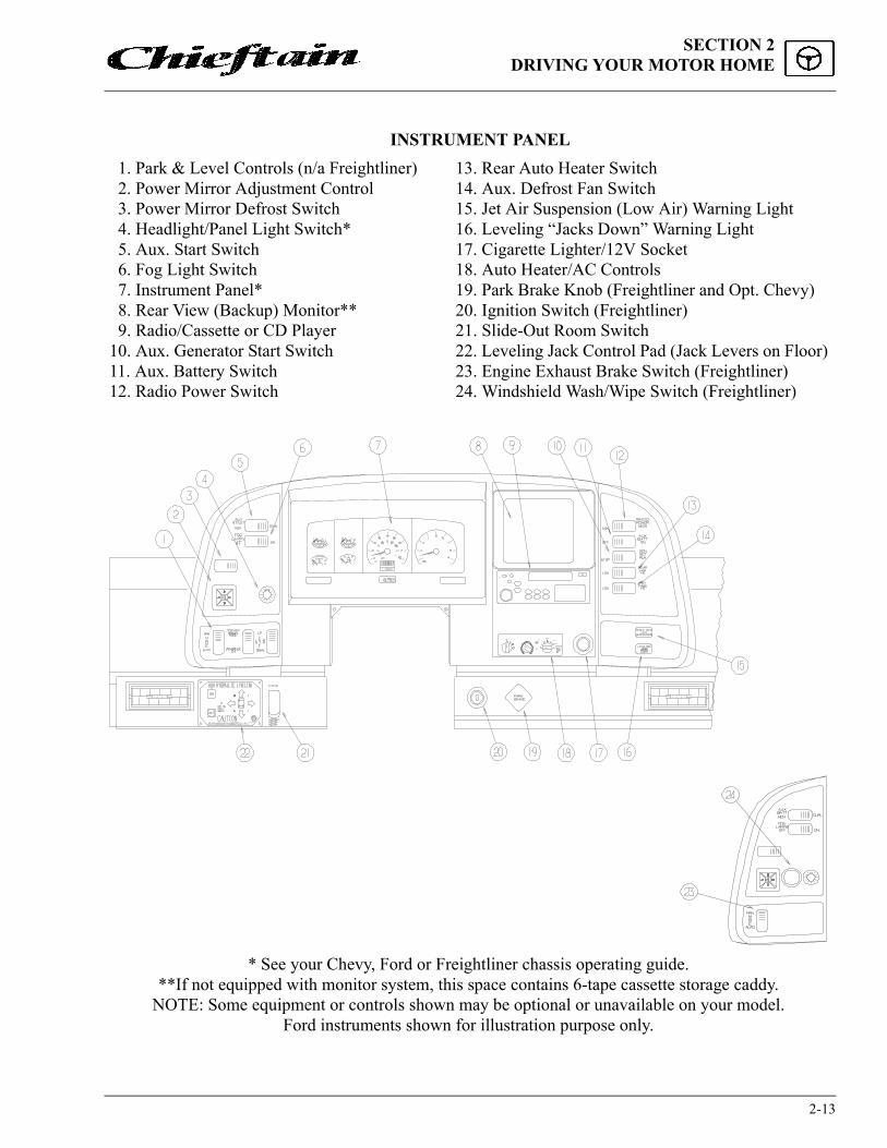
1. Park & Level Controls (n/a Freightliner) 2. Power Mirror Adjustment Control 3. Power Mirror Defrost Switch 4. Headlight/Panel Light Switch* 5. Aux. Start Switch 6. Fog Light Switch 7. Instrument Panel* 8. Rear View (Backup) Monitor** 9. Radio/Cassette or CD Player10. Aux. Generator Start Switch11. Aux. Battery Switch12. Radio Power Switch
INSTRUMENT PANEL13. Rear Auto Heater Switch14. Aux. Defrost Fan Switch15. Jet Air Suspension (Low Air) Warning Light16. Leveling “Jacks Down” Warning Light17. Cigarette Lighter/12V Socket18. Auto Heater/AC Controls19. Park Brake Knob (Freightliner and Opt. Chevy)20. Ignition Switch (Freightliner)21. Slide-Out Room Switch22. Leveling Jack Control Pad (Jack Levers on Floor)23. Engine Exhaust Brake Switch (Freightliner)24. Windshield Wash/Wipe Switch (Freightliner)
* See your Chevy, Ford or Freightliner chassis operating guide.**If not equipped with monitor system, this space contains 6-tape cassette storage caddy.
NOTE: Some equipment or controls shown may be optional or unavailable on your model.Ford instruments shown for illustration purpose only.

SECTION 2DRIVING YOUR MOTOR HOME
2-14
MULTI-FUNCTION SIGNALLEVERThe multi-function signal lever con-
trols the turn signals, high/low beam changing, windshield washer, wipers and wiper delay, and the electronic speed control (cruise) on some models.
See your chassis operating guide for complete operating information.
HEADLIGHT BEAM CHANGE AND TURN SIGNALS
Move multi-function lever upward for right turn signal and downward for left turn signal.
Pull end of handle toward you to switch high beam to low, or low beam to high.
WINDSHIELD WIPERS AND WIPER DELAY
See your chassis operating guide for complete operating information.
WINDSHIELD WASH/WIPE SWITCH(Freightliner Chassis)
Wash: Press the control knob to pump washersolution onto the windshield. The wiper will alsobegin operating. The wiper will continue for 5wipes after you release the washer knob.
Wiper: Rotate the outer knob pointer to the de-sired setting - Delay, Low or Hi.
Delay: Turn the outer knob pointer to “Delay”.Turn the center (wash) knob to set the time youwant between wipes, from 1 second (all the wayleft) to about 90 seconds (all the way right).
HAZARD WARNING LIGHTSSee chassis manual or "Instrument Panels" in
this section for location of hazard flasher switch. See also Section 3 for further operating informa-tion.
CRUISE CONTROLThe electronic speed control (cruise) allows
you to maintain a steady speed and relieve driv-ing strain while traveling long distances.
See your chassis operator manual for com-plete instructions and precautions on the cruise control.
COMFORT CONTROLSAUTO AIR CONDITIONER/HEATER
Controls for the air conditioner, heater, de-froster and vent are all combined into one control panel. Refer to the following instructions for use of individual controls.
1. Front Heater Fan Switch2. Temperature Control Knob3. Mode Selection Knob
Center Knob:Push for WashTurn to AdjustWiper Delay
Outer Knob:Turn to SelectWiper Speed
WARNINGDo not operate the cruise control on icy or extremely wet roads, winding roads, in heavy traffic, or in any other traffic situation where a constant speed cannot be maintained.
Fan Switch TempControl
ModeControl

2-15
SECTION 2DRIVING YOUR MOTOR HOME
Heating
A. For maximum heating1. Turn the temperature control knob
toward the COOL (blue) zone to the desired comfort position.
2. Turn the temperature control knob to WARM (red).
3. Place the fan switch to high (largest dot).
B. For reduced heating:1. Turn the temperature control knob to the
left to an intermediate setting.2. Adjust the fan speed for desired volume.
Defrosting
A. For maximum defrosting and defogging:1. Turn the mode control knob to DEF.2. Turn the temperature control knob to
WARM (red).3. Turn the fan switch to high (largest dot).4. Turn on auxiliary (dash) fans if addi-
tional air movement is neededB. For reduced defrosting:
1. Turn the temperature control knob to the left to an intermediate setting.
2. Adjust the fan speed for desired volume.
Ventilation
A. To vent outside air into the vehicle when nei-ther heating or cooling is required.1. Turn the mode selection knob to vent.2. Turn the temperature control knob all the
way to the left to the COOL (blue).3. Adjust the fan speed for desired volume.
Air Conditioning
A. For maximum cooling.1. Turn the mode selection knob to MAX
A/C.
2. Turn the temperature control knob all the way left to the COOL (blue) position.
3. Turn the fan speed switch in to high (largest dot).
OffWhen no heating, cooling or defrosting are
required:
1. Turn the mode selection knob to OFF. This will shut off the fan and prevent outside air from entering the unit.
NOTE: The automotive air conditioner is not de-signed to cool the entire interior of the motor home, but is intended to cool the driver's compartment only.
REAR AUTO HEATER
To provide auxiliary heat to the rear of the vehicle, turn the rear heater fan switch to the desired speed.
RearAutomotiveHeaterSwitch

SECTION 2DRIVING YOUR MOTOR HOME
2-16
STEREO SOUND SYSTEM
Radio Cassette Player (Standard) orRadio Compact Disc Player (Optional)
Your coach may be equipped with a standard AM/FM stereo radio cassette player or an optional AM/FM stereo radio/CD player. Both of these systems provide high quality stereo sound for your listening enjoyment while traveling or parked.
Refer to the individual radio manufacturer’s information supplied in your InfoCase for detailed operating and care instructions.
Radio Power SwitchThe radio power switch lets you connect the
dash radio to the coach batteries with the ignition switch turned off for listening while parked. This prevents accidental draining of the chassis (start-ing) battery during prolonged operation of the radio.
Deluxe Sound System (Optional)Your coach may be optionally equipped with
a deluxe sound system featuring special high-output cube speakers and subwoofers to enhance your listening enjoyment.
Place the Radio Power Switch in AUX posi-tion and the Ignition Switch in ACC position.
A speaker selector switch in the front over-head cabinet (video center) lets you switch the deluxe speakers to your desired sound source, whether the dash radio or the TV and VCR for theater surround sound listening.
COMPACT DISC CHANGER - OptionalThe remote CD changer is located out
of sight in the overhead cabinet above the driv-er’s compartment. The changer cartridge holds up to 6 compact discs for several hours of listen-ing enjoyment.
The controls are incorporated into the dash radio. See the Compact Disc Changer System operating guide in your InfoCase for complete operating instructions and basic troubleshooting.
AUX. START SWITCHThis switch can be used to provide emergency
starting power from the house batteries if the automotive battery is dead.
SPEAKER SOURCE SELECT SWITCH
RADIO TV

2-17
SECTION 2DRIVING YOUR MOTOR HOME
AUXILIARY BATTERY (Aux. Batt) SWITCH
The AUX BATT switch disconnects the aux-iliary (house) batteries from the 12-volt system of your coach to avoid long-term battery drain by electrical items that are hooked directly to the house batteries.
Always leave this switch ON except during long storage periods (a month or more).
CB RADIO WIRING (Optional)
If your coach is pre-wired for CB radio instal-lation, the wires are located beneath the dash to the left of the steering wheel.
Look for a pair of wires, purple (+) and green (-), with connectors and flag labels, suspended from the wiring harness.
Be sure to read the wire labels before install-ing a CB radio. The labels contain important in-formation and cautions.
SWR ADJUSTMENTTo adjust CB antenna SWR (standing wave
ratio), turn the adjusting ring of the antenna to achieve the lowest SWR reading. This procedure will help optimize transmitting and receiving ca-pabilities of the radio system.
If engine bat-tery is dead, press while turning igni-tion key for emergency starting power
TO CB RADIO
TOCB RADIO WIRING
LABEL
CB ANTENNACABLE WIRE ASM-IP,MAIN
CB Radio Wiring
CB POWER PROVISION
RED + 12 VBLACK GROUNDCOAX ANTENNA(SEE REVERSE ALSO)
CB POWER PROVISIONPurpleGreenCoax
+12 VGroundAntenna
(See Reverse Also)
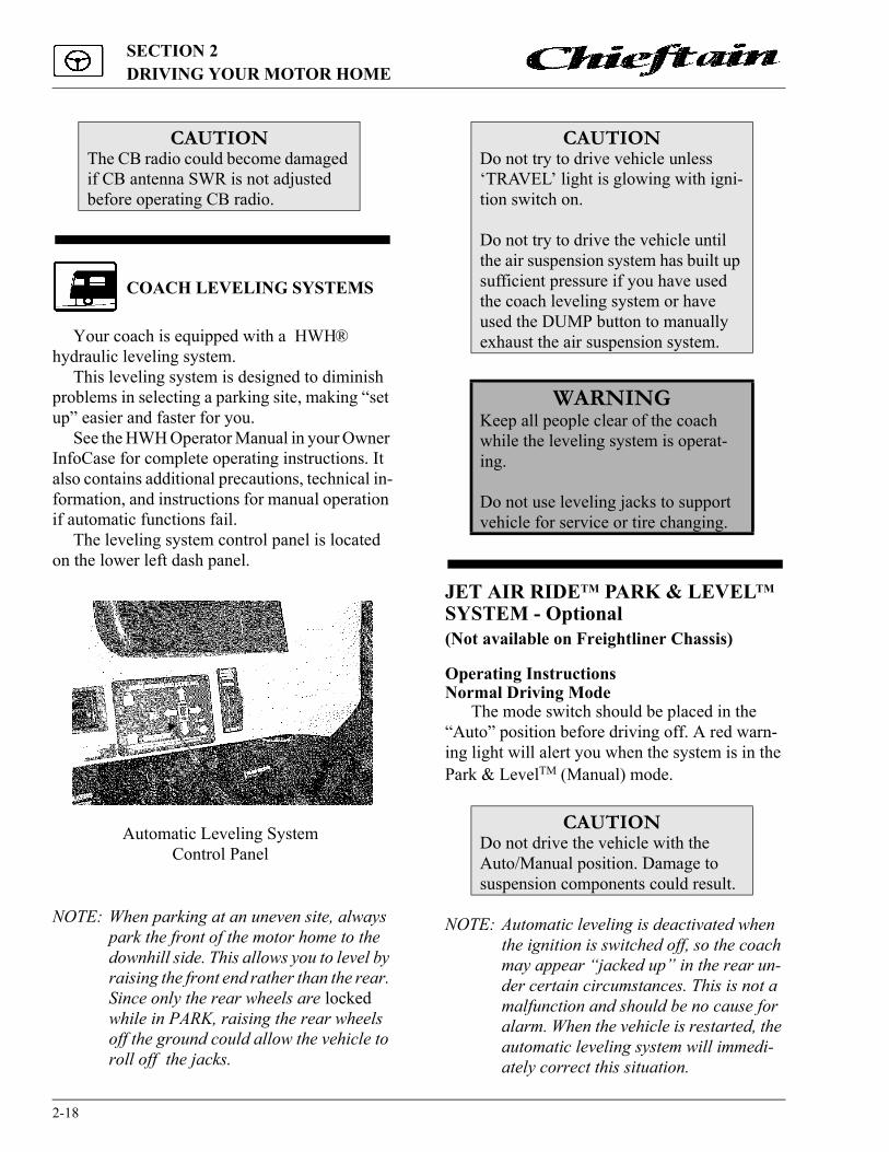
SECTION 2DRIVING YOUR MOTOR HOME
2-18
COACH LEVELING SYSTEMS
Your coach is equipped with a HWH® hydraulic leveling system.
This leveling system is designed to diminish problems in selecting a parking site, making “set up” easier and faster for you.
See the HWH Operator Manual in your Owner InfoCase for complete operating instructions. It also contains additional precautions, technical in-formation, and instructions for manual operation if automatic functions fail.
The leveling system control panel is located on the lower left dash panel.
NOTE: When parking at an uneven site, always park the front of the motor home to the downhill side. This allows you to level by raising the front end rather than the rear. Since only the rear wheels are locked while in PARK, raising the rear wheels off the ground could allow the vehicle to roll off the jacks.
JET AIR RIDETM PARK & LEVELTM SYSTEM - Optional(Not available on Freightliner Chassis)
Operating InstructionsNormal Driving Mode
The mode switch should be placed in the “Auto” position before driving off. A red warn-ing light will alert you when the system is in the Park & LevelTM (Manual) mode.
NOTE: Automatic leveling is deactivated when the ignition is switched off, so the coach may appear “jacked up” in the rear un-der certain circumstances. This is not a malfunction and should be no cause for alarm. When the vehicle is restarted, the automatic leveling system will immedi-ately correct this situation.
CAUTIONThe CB radio could become damaged if CB antenna SWR is not adjusted before operating CB radio.
Automatic Leveling SystemControl Panel
CAUTIONDo not try to drive vehicle unless ‘TRAVEL’ light is glowing with igni-tion switch on.
Do not try to drive the vehicle until the air suspension system has built up sufficient pressure if you have used the coach leveling system or have used the DUMP button to manually exhaust the air suspension system.
WARNINGKeep all people clear of the coach while the leveling system is operat-ing.
Do not use leveling jacks to support vehicle for service or tire changing.
CAUTIONDo not drive the vehicle with the Auto/Manual position. Damage to suspension components could result.

2-19
SECTION 2DRIVING YOUR MOTOR HOME
Park & LevelTM SystemThe Park & Level system incorporates elec-
tronic air distribution controls for vehicle level-ing purposes. It allows air spring pressure to be manually adjusted up-and-down or side-to-side to simulate the function of a hydraulic leveling system. This provides the vehicle owner with a reasonable degree of flexibility in parking/camp-ing site selection.
Park & LevelTM ControlsThe Park & Level control panel is located at
the lower left-hand side of the dash. It contains 3 rocker switches, a compressor indicator light; and a manual mode warning light.
LevelingPress the mode switch to “Manual”. A red
warning light will illuminate to indicate that the leveling feature is activated. Level the vehicle by operating the level switches.
� When raising the rear of the vehicle, operateboth springs at the same time to provide max-imum lifting power.
� When parked on a side hill, raise both springsas mentioned above, then lower the spring onthe “uphill” side until the vehicle is level.
� When you’re ready to drive off, switch themode to “Automatic” and wait until thesprings automatically adjust for road travel.
NOTE: The air bags will inflate and deflate slightly about 5 to 8 times until the coach is leveled.
Compressor LightThe green indicator light labeled “Compres-
sor On” will illuminate only while the compres-sor is operating. When air pressure depletes to a preset minimum amount, the compressor will op-erate until maximum pressure is restored.
It is normal for the compressor to operate pe-riodically while driving to maintain air pressure in the system. It will also operate for a few min-utes after starting the vehicle and switching the Auto/Manual switch back to “Auto” (when Park
& LevelTM has been in use) to restore air pressure released during leveling.
Air Suspension Warning Light
System FuseIf the Jet Air Ride system fails to operate,
check the 30A plug-in fuse located on automo-tive circuit breaker/fuse panel on the firewall below the left side of the dash. Turn twist lock to the left to remove protective cover. Pull cover outward and up to remove.
CAUTIONThe rear air suspension warning light, located on the lower instrument panel to the right of the steering column, will illuminate if a failure should occur in the tax axle/rear suspension system. If this should occur while driving, the vehicle may be carefully driven to the nearest Winnebago or Itasca dealer or a qualified truck air suspension service center. Although this condition does not totally disable the vehicle, it will cause less than sat-isfactory ride characteristics and should be serviced as soon as possible to restore proper performance.
Automotive Circuit Breakers & Fuses(Beneath left side of dash)

SECTION 2DRIVING YOUR MOTOR HOME
2-20
Always replace fuse with one of equal size and amperage rating.
Periodic MaintenanceSee page 9-7.
SLIDEOUT ROOM EXTENSION
The slideout room extension provides a spa-cious living area at the push of a button. The slideout room is extended and retracted using a hydraulic mechanism with an electronic control system. The slideout control switch is located on the lower left dash area.
Travel LatchesThe Travel Latches must be released before
attempting to extend the room or damage to the coach will result.
The travel latches are designed only to help keep the room extension secured against the coach sidewall to maintain an effective weather seal while the vehicle is in motion. They are not designed to withstand the force exerted by the hydraulic extension mechanism and will not pre-vent accidental extension of the room.
The travel latches are located at the bottom edges of the slideout room side walls.
To Release:� Pull the latch handle outward and down.� Lift the black metal D-ring and push the J-
hook back to disengage.� Push the D-ring down to the floor and lift the
latch handle upward against the wall.� Repeat for other side of room.
.
To Fasten:� Pull the latch handle outward and down.� Lift the black metal D-ring up and engage the
J-hook.� Lift the latch handle upward and lock against
the wall.� Repeat for other side of room.
NOTE: If latches become loose and will not stay fastened, see your dealer for proper ad-justment.
To Extend SlideOut Living Room:
� Level the coach.
� Leave leveling system on to provide power to the slideout mechanism.
� Turn the ignition switch to ON or ACC and set the Parking Brake. An interlock relay system will then provide power to the slide-out control switch.
� Release travel latches.
� Press slideout switch and hold until room is fully extended, then release switch.
CAUTIONRelease slideout room travel latches before attempting to extend slideout room. Fasten travel latches before driving vehicle. See instructions below.
WARNINGKeep all persons clear of the slideout room and moving parts while extend-ing or retracting. Do not occupy the slideout room while it is being extended or retracted.
LatchHandle
J-Hook
D-Ring
Travel Latches

2-21
SECTION 2DRIVING YOUR MOTOR HOME
Before Retracting Slideout RoomIf it has rained recently before you retract the
slideout room, we recommend using the hydrau-lic leveling system to lean the coach and drain off any excess water possibly remaining on the roof before retracting. Lean the coach slightly to the left (driver’s side) as shown by raising both right side jacks to let excess water flow away from the rooftop weatherseal and toward the outside of the slideout roof.
To Retract Slideout Room:
� Remove all items from the coach living room floor. Turn leveling system on to provide power to the slideout control switch.
� Press slideout switch and hold until room is fully retracted, then release the switch.
High Wind PrecautionWe remind you to be aware of high winds
while the room is extended because of the effect they can have on the roof awning. It is a good idea to retract the room any time high wind con-ditions exist that would also make it necessary to
roll in the patio side awning. This will protect the slideout room awning from possible wind dam-age.
If Slideout Room Will Not Operate(Troubleshooting)
� The chassis battery may be low on charge. Press the Aux. Start switch on the dash to the momentary (MOM) position while pressing the slideout control switch. This momentarily connects the coach batteries to assist in re-tracting the room.
� One of the fuses may be blown. Fuses are lo-cated on the interior firewall beneath the dash, beneath the instrument panel dash pod, and inside the leveling control pad housing.
� If the batteries and fuses are okay, there may be a failure in the hydraulic system or electri-cal system. See “Manual Retracting Instruc-tions” for help.
Slideout Room Extension Emergency Crank-In Procedure -(Use only when room will not retract using control switch)
If a failure occurs in the slideout electrical or hydraulic systems, and the room will not retract using the control switch, you can manually crank the room in using an emergency winch system described below. The winch is generally stored beneath the dinette seat or in a cargo compart-ment on the passenger side of the coach.
Step 1 - Relieve Hydraulic Line Pressure
� Open the hydraulic pump valves to release hydraulic line pressure and let fluid bypass into the fluid reservoir. The pump is located beneath the coach on a bracket mounted to the coach frame near the rear of the vehicle. The valves can be reached best by lying on your back and reaching up between the mounting brackets.
CAUTIONAlthough there is an awning over the roof of the slideout room, there is a possibility of debris getting onto the roof. Because the slideout roof is drawn into the interior of the coach when retracted, be sure there is no debris, such as excessive dirt, tree seeds, twigs, leaves, etc. on the roof before retracting.

SECTION 2DRIVING YOUR MOTOR HOME
2-22
� Open the 2 T-handle valves on the inside end of the pump only. Turn T-handles counter-clockwise to open.
DO NOT OPEN ANY OF THE 4 VALVES ON THE OUTSIDE END OF THE PUMP because they regulate the leveling jacks.
NOTE: The T-handles may turn easily at first but will become more difficult to turn as in-ternal springs are compressed. Be sure to open both valves completely (about 6 turns of each T-handle).
Step 2 - Attach Winch and Crank RoomInward� Remove the register from the floor heat duct
and anchor the winch in the floor. Insert the winch retainer bracket into the duct cutout in the floor as shown.
NOTE: Be sure the bracket extensions face away from the slideout room as shown for proper support while cranking.
� Insert the winch strap hook into the sewn loop end of the strap beneath the couch.
� Be sure the winch ratchet pawl is in the lock-ing position (against the gear teeth) before cranking.
� Crank the winch handle clockwise slowly, a few “clicks” at a time, until the room is fully retracted. Allow about 10 minutes to crank room in fully.
NOTE: Attempting to crank the room in too quickly will raise pressure in the hydrau-lic fluid lines and make cranking more difficult.
� Unhook the winch and return the winch and straps to storage locations. Release the strap by putting slight pressure clockwise on the crank handle, then moving the ratchet pawl to the free-wheel position (away from gear teeth).
WARNINGStop engine, place transmission in park position and apply parking brake before lying beneath vehicle for this procedure.
Slideout Room Hydraulic Pump
Hydraulic Pressure Release(T-handle) Valves - viewed
from center of vehicle
STRAPTO COUCHWINCH
FLOOR TUBE BRACKETTO SLIDEOUTROOM
DUCT SPACE
HEAT REGISTER

2-23
SECTION 2DRIVING YOUR MOTOR HOME
Step 3 - Secure Travel Latches and Close Hy-draulic Line Valves� Fasten the slideout room Travel Latches as
shown.
� Close the hydraulic pump valve T-handles completely.
NOTE: Close the valves snugly, but do not over-tighten. Overtightening may cause inter-nal damage to the valves.
� See your dealer for service of the room exten-sion system before using again.
Further InformationSee the HWH Hydraulic Room Extension op-
erating guide included in your InfoCase for fur-ther instructions and troubleshooting information.
LatchHandle
J-Hook
D-Ring
Travel Latches


3-1
SECTION 3IN CASE OF DRIVING EMERGENCY
HAZARD WARNING FLASHER
The hazard warning flasher provides addition-al safety when the vehicle must be stopped on the side of the roadway and presents a possible haz-ard to other motorists. When the flasher is on, it serves as a warning to the other drivers to ap-proach and overtake your vehicle with caution.
The front and rear turn signals will flash inter-mittently when the flashers are in operation. When it is necessary to leave the vehicle, the flasher system will continue to operate with the ignition key removed.
See your Chevy, Ford or Freightliner chassis operator’s guide for information on operating the hazard warning flashers.
IF YOU GET A FLAT TIRE
In case of sudden tire failure, avoid heavy brake application. Gradually decrease speed. Hold steering wheel firmly and move slowly to a safe, off-road place. Park on a level spot, turn off the ignition, and turn on the hazard warning flasher system.
SPARE TIRE STORAGEThe spare tire is mounted on a cable hoist as-
sembly beneath the rear of the vehicle.
NOTE: Freightliner Diesel Chassis: Because of the size and weight of this vehicle and the possible complications involved in tire changing, this chassis is not supplied with a spare tire. If you experience a tire related road emergency, call the number on your Winnebago Industries Premium Roadside Assistance card. A tire road service unit will be quickly dispatched to your location to service your tire on the spot. A qualified tire road service center has the necessary equipment and exper-tise to handle road tire emergencies quickly and safely.
To Access Spare:1. Remove the primary latch bracket from the
tire hoist assembly. To do this unscrew the wing nut and remove the bracket from the lower side of the carriage plate at the center of the wheel as shown.
2. Insert the crank handle through the hole in the bumper. Be sure the pins on the crank handle engage with the slots in the hoist shaft.
3. Turn the crank handle counter-clockwise to lower the tire to the ground.
4. Remove the spare from the carriage plate by passing the plate through the large center
WARNINGOperating the hazard warning flashersystem while moving on the highwayis illegal.
CAUTIONBe sure hoist is tight before looseningprimary latch. Tire could be free todrop if hoist is not tightened fully.
CARRIAGEPLATE
PRIMARYCATCH
WASHER
NUT
CRANKHANDLE

3-2
SECTION 3IN CASE OF DRIVING EMERGENCY
hole of the wheel.
To Stow Spare:1. Insert the carriage plate through the wheel
and align so the retainers will engage into the center hole of the wheel.
2. Insert the crank handle into the bumper and crank clockwise to pull the tire up. Check to see that the carriage plate is firmly engaged in the center hole of the wheel as the cable becomes taut.
3. When the tire makes snug contact with the frame, crank the handle until a crisp break is heard and felt. Crank until a second crisp break occurs. This assures the hoist mecha-nism has reached its maximum stowing force. Remove and stow the crank handle.
4. Slide the primary latch bracket back onto the bolt. Be sure the lower hook-lip engages onto the lip on the underside of the carriage plate, then place the washer and nut onto the bolt and tighten securely.
MOTOR HOME JACKING AND TIRE CHANGING
NOTE: The jack referred to in the following in-structions is not supplied with the vehi-cle. You can obtain one from your dealer.
A jack is designed for use as a tool for chang-ing tires only, not for use as a leveling device or as a support when servicing.
SAFETY PRECAUTIONSBefore trying to change either the front or rear
tires, follow these precautions:1. Park vehicle on level surface only.2. Turn off engine and set parking brake.3. Turn on hazard warning flasher.4. Block both front and back of tire on opposite
side of vehicle from wheel to be removed.5. On soft ground, use a board or other material
under jack as a firm base to ensure that the jack will not shift.
JACKING POINTS ON VEHICLEChevy: Front-under lower control arm; Rear-un-der axle.Ford or Freightliner: See your chassis manual for specified jacking points.
FRONT WHEELBefore trying to remove the front wheel, ob-
serve the above safety precautions, then follow the procedure below:1. Place jack under jacking point specified by
chassis manufacturer. See Jacking Points above. Position jack so it may be operated without placing your body beneath vehicle.
2. Screw jack extension pad out (up) until it touches jacking point surface.
3. Begin jacking until jack is firmly positioned and just begins to bear weight, but do not lift tire off the ground.
4. “Crack” wheel nuts loose with lug wrench, but do not unscrew nuts yet.
WARNINGWe advise you to obtain qualified road service whenever possible. Do not try to change a tire yourself except under emergency conditions, and only by closely following instruc-tions in this manual and the chassis operating guide.
If you do satisfactorily complete an emergency tire change, we recom-mend that you have the wheel nuts checked and properly torque tight-ened by qualified service personnel as soon as possible.
After a wheel has been properly torqued and inspected by qualified service personnel, it should be rechecked after traveling 100 miles, then again at each oil change.
WARNINGTire change procedures should beused in emergency situations only.The operator is advised to obtainqualified road service when possible.

3-3
SECTION 3IN CASE OF DRIVING EMERGENCY
5. Resume jacking until wheel is free of ground.
6. Remove wheel nuts and wheel; put spare wheel in place.
7. Install wheel nuts and tighten as much as possible with wheel and tire off the ground.
8. Lower tire until tire just contacts the ground. Tighten nuts with lug wrench in sequence recommended by chassis manufacturer.
9. Finish lowering jack, then remove jack and blocks.
DUAL REAR WHEELSBefore trying to remove the rear wheel, follow
safety precautions in the beginning of the motor home jacking procedures. Then follow the proce-dure below:1. Place jack under jacking point specified by
chassis manufacturer. See Jacking Points on previous page. Position jack so it may be operated without placing your body beneath vehicle.
2. Screw jack extension pad out (up) until it touches jacking point surface.
3. Begin jacking until jack is firmly positioned and just begins to bear weight, but do not lift tire off the ground.
4. “Crack” wheel nuts loose with lug wrench, but do not unscrew nuts yet.
5. Resume jacking until wheel and tire are free of ground.
6. Remove wheel nuts and wheel.
NOTE: When installing the outer dual wheel and tire assembly, rotate the outer dual wheel so valve stems are accessible but not touching one another. In some cases this means that the inner and outer valve stems should be in separate wheel cutout locations
NOTE: When installing or tightening dual wheels, both wheels on the same side must be off the ground (not resting on the inner dual). This minimizes the possibili-ty of loose wheels after correct mounting torque is applied.
7. Mount spare wheel on studs and replace wheel nuts. Refer to your chassis operating guide for wheel nut torque and tightening sequence.
WHEEL NUTSTo properly seat the wheel nuts and to elimi-
nate the possibility of the wheel nuts becoming loosened while driving, they should be tightened at frequent intervals to the torque specified in your chassis operating guide. This is especially important after the first 100, 1,000 and 6,000 miles of operation after replacement of a wheel or wheel nuts.
RECOVERY TOWING
When calling a professional towing service, we recommend that you advise them of your coach length and approximate front axle weight. This will allow the towing operator to determine the proper towing equipment to use. (This infor-mation is found on the vehicle certification label located to the left of the steering wheel.)
We recommend that you ask for an underlift (wheel lift or frame lift) type towing assembly for safe towing.
Winnebago Industries does not assume re-sponsibility for damage incurred while towing this vehicle.
WARNINGUpon satisfactory completion ofemergency tire change, it is highlyrecommended that wheel nuts beproperly torqued and inspected byqualified service personnel as soon aspossible.
WARNINGDO NOT crawl under the vehiclewhen it is supported by a jack.
3-4
SECTION 3IN CASE OF DRIVING EMERGENCY
NOTE: Consult the chassis operating guide for any additional towing instructions or precautions provided by the chassis manufacturer.
NOTE: Know and obey all state and local towing regulations. Tow at reduced speed.
JUMP STARTING
CONNECTING JUMPER CABLES
1. Make sure that the other vehicle has a 12-volt battery and negative ground compatible with your vehicle’s electrical system.
2. Position the vehicle with the good battery so that the jumper cables will reach, but do not allow the vehicles to touch.
3. Turn off all electrical accessories, motors, and lights except those needed for safety or to light up the work area. Place automatic transmission in P (Park). Be sure parking brakes are engaged in both vehicles.
4. If the weak battery has filler caps, make sure the electrolyte is at proper level. Add dis-
CAUTIONDo not lift on bumper. Damage will result to front end body parts.
WARNINGStay out from beneath the motorhome while it is suspended by thetowing assembly unless the vehicle isadequately supported by safetystands. Do not allow passengers tooccupy a towed vehicle.
WARNINGAutomotive batteries produce caustic acid, explosive gases, and electrical current which may cause burns. It is important that the instructions below are followed exactly, or personal injury (particularly to eyes) or prop-erty damage may result due to battery explosion, battery acid, or electrical (short circuit) burns.
• NEVER smoke near the battery or expose it to open flame or electri-cal sparks.
• Wear eye protection or shield your eyes while working near bat-tery, in case an explosion does occur. NEVER lean over a bat-tery.
• Do not allow battery fluid to con-tact eyes, skin, clothing, or painted surfaces. Immediately flush any contacted area with water. If eyes are affected, seek medical help after flushing.
• Remove all metal jewelry to lessen the risk of a short circuit occurring.
3-5
SECTION 3IN CASE OF DRIVING EMERGENCY
tilled water if fluid is low. If electrolyte is not visible or appears to be frozen - do not attempt jump starting! A battery may rup-ture or explode if the electrolyte is frozen or not filled to the proper level.
5. Connect one end of the positive “+” (red) jumper cable to the positive “+” terminal of the weak battery. Connect the other end to the positive “+” terminal of the charged bat-tery.
6. Connect one end of the negative “-” (black) jumper cable to the negative “-” terminal of the charged battery.
7. Finally, connect the remaining end of the negative “-” (black) cable to a solid, metal grounded location on the engine of the vehi-cle with the weak battery, at a point at least 18 inches from the battery. Do not connect to any moving parts. THE MAIN SAFETY PRECAUTION IS TO MAKE THE FINAL GROUND CONNECTION ON THE ENGINE AT A SAFE DISTANCE FROM THE BATTERY. THIS HELPS TO REDUCE THE CHANCE OF EXPLO-SION DUE TO SPARKS.
8. Start the engine of the vehicle with the charged battery, and allow it to run for a few minutes at moderate r.p.m. Then start the engine of the vehicle with the discharged battery.
9. Reverse the above sequence EXACTLY when removing the jumper cables. Start by removing the cable from the ground location on the engine first, then continue in reverse sequence.
CONNECTING A BATTERY CHARGER
To connect a battery charger, first make sure the engine is switched off. Disconnect the posi-tive (+) lead from the battery. Never disconnect the battery while the engine is running or alter-nator damage could result.
Connect the positive “+” (red) lead of the charger to the positive “+” terminal on the battery. Next, connect the negative “-” (black) lead of the charger to a suitable ground. Finally, plug in or switch on the charger.
To disconnect the charger after charging, un-plug the charger from the electrical outlets, re-move the charger leads from the vehicle, and reconnect the vehicle leads to the battery.
ENGINE OVERHEAT
An engine will overheat if the coolant is low or there is a loss of coolant because of one or more of the following:� a leak in the cooling system� a hose failure� a drive belt breaking� water pump failure
Also, be aware of the following situations, which can cause temporary engine overheating:� climbing a long hill on a hot day � idling while stopped in traffic for long peri-
ods of time� towing a trailer or automobile � stopping after a period of high speed driving
If the TEMP indicator on the instrument panel shows a rise in engine coolant temperature while driving, take the following steps to attempt to lower the overheating condition:� If you are using the automotive air condition-
er, turn it off.� If you are stopped in traffic, shift the trans-
mission into P (Park), and engage parking brake.
If the temperature does not drop within a minute or two:
WARNINGDo not attempt to push-start this vehi-cle. Damage to the transmission orother parts of the vehicle could occur.
WARNINGOperating a vehicle under a severeoverheating condition can result indamage to the vehicle and may resultin personal injury.

3-6
SECTION 3IN CASE OF DRIVING EMERGENCY
� Pull the vehicle over to the roadside as soon as it is safe to do so.
� Place the transmission in P (Park) and press the accelerator to increase engine speed (r.p.m.’s) to twice that of normal idle speed, and hold it there for approximately two or three minutes.
� If engine temperature does not go down, turn the engine off and wait until the engine has cooled before attempting to open the hood.
If you see or hear steam escaping from the ra-diator or the engine compartment or have any other reason to suspect an extreme engine over-heating condition, pull the vehicle over to the roadside as soon as it is safe to do so, stop the en-gine and get out of the vehicle.
When no trace of escaping steam is heard or seen, open the hood to check for the cause of the overheat. Check hose connections and tighten if necessary. Make sure there are no broken belts, pulleys or hoses before adding any coolant to the radiator.
For further information in case of overheating, consult your chassis operating guide.

4-1
SECTION 4TRAVELING WITH YOUR MOTORHOME
(See also SAFETY PRECAUTIONS, Section 1 of this manual.)
LOADING THEVEHICLE
When loading the vehicle, distribute the cargo load equally so that you do not exceed either the Front or Rear Gross Axle Weight Rating (GAWR) or the Gross Vehicle Weight Rating (GVWR). The Gross Axle Weight Rating (GAWR) means the weight value specified by the chassis manufacturer as the load carrying capacity of a single axle sytem as measured at the tire-to-ground interfaces. This is the total weight a given axle is capable of carrying. Each axle has its own rating.
Have your vehicle weighed to determine the proper load distribution for your vehicle. Also distribute cargo side-to-side so the weight on each tire or dual set does not exceed one half of the GAWR for either axle.
For example, if the Front GAWR is 6,000 lbs., there should be no more than 3,000 lbs. on each tire. (If the left side weighs 3,100 lbs. and the right side weighs 2,700 lbs., at least 100 lbs. of the load should be shifted from the left side to the right side.) The GVWR is listed on the Vehicle Certification Label. (See page 0-3).
The total combined weight allowed for the vehicle, including trailer towing load weight, is known as the Gross Combined Weight Rating (GCWR). If trailer towing is not recommended, the GCWR will equal the GVWR.
NOTE: We recommend that you dump all hold-ing tanks before traveling to avoid carrying unnecessary weight.
FRONT AXLE TIRE ALIGNMENT
We recommend that you have the front sus-pension and steering alignment checked and adjusted after you have fully loaded the vehi-cle according to your needs. Thereafter, have alignment inspected periodically to maintain vehicle steering performance and prevent un-even tire wear.
WEIGHING YOUR LOADED VEHICLE
To check the weight of your fully loaded coach, locate a commercial weighing scale that is capable of weighing large trucks.
Drive the entire coach onto the scale. This weight should not exceed the Gross Vehicle Weight Rating (GVWR) specified on the Vehicle Certification Label near the driver seat. (See sam-ple on page 0-3.)
To determine the weight on either front or rear axle, drive that axle only onto the scale. Neither axle weight should exceed the corresponding maximum axle weight rating specified on the certification label.
CAUTIONThe weight of the loaded vehicle (including options, attachments, pas-sengers, water, fuel, luggage and all other cargo) must not exceed the GVWR or GAWR of either axle.
GAWR (Both axles)
Front GAWR(Front axle only)
Rear GAWR(Rear axle only)

SECTION 4TRAVELING WITH YOUR MOTOR HOME
4-2
MAXIMUM OCCUPANCY
The following label is placed in a visible location in the driver compartment.
The number of belted seating positions in your motor home may exceed the number people used to determine maximum coach occupancy, called the Net Carrying Capacity (NCC) in the U.S. or Cargo Carrying Capacity (CCC) in Can-ada.
To calculate the NCC or CCC, Winnebago uses vehicle sleeping capacity, however your coach may be equipped with more belted seat-ing positions than sleeping positions to give pas-sengers a choice of seating arrangements. You may use all of the belted seating positions pro-viding you stay within your vehicle’s GVWR listed on the Vehicle Certification Label (see page 0-3). However you use or load your vehi-cle, it is your responsibility to keep the weight within its stated gross vehicle weight rating.
ROOF LOADING
The roof is capable of carrying some light-weight articles while the vehicle is in motion. A roof-mounted luggage carrier designed for this purpose is available from your dealer. However, roof load while the vehicle is in motion is not to exceed 10 pounds per square foot or a maximum of 100 pounds.
When the vehicle is stationary, a cargo load of 100 pounds plus the weight of a 225 pound per-son to load the cargo or to conduct inspection and maintenance is permissible.
Weight added to both the roof and the trailer hitch contribute to the gross vehicle weight, which must not exceed the vehicle’s GVWR.
CAR OR TRAILER TOWING
Chevy/Ford ChassisHitch pulling cap: 5,000 lbs.Tongue weight: 350 lbs. max.
Freightliner ChassisHitch pulling cap: 5,000 lbs.Tongue weight: 500 lbs. max.
The factory installed towing hitch on this coach is rated to pull a 5,000 lb. load (max.), however the vertical (tongue) weight may vary according to chassis and model combinations. Do not exceed either the GVWR, the rear axle GAWR, or the chassis GCWR. See preceding items “Loading the Vehicle” and “Weighing Your Loaded Vehicle” for explanation of weight ratings.
The combined weight of the coach and the towed vehicle should not exceed the coach’s Gross Combined Weight Rating (GCWR). Also, the combined weight of the coach and the towed vehicle’s hitch ball weight should not exceed the coach’s Gross Vehicle Weight Rating (GVWR) or its rear Gross Axle Weight Rating (GAWR) listed on the Vehicle Certification.
Because of individual vehicle use and loading habits, we recommend weighing the vehicle while fully loaded to avoid exceeding any of the listed Gross Weight Ratings. See “Vehicle Certi-fication Label” on page 0-3 for information on gross weight ratings.
Towing will affect vehicle handling, durabili-ty and fuel economy. Exceeding any of the listed Gross Weight Ratings will result in unacceptable overall vehicle performance. Maximum safety and satisfaction when towing depends on proper use of correct equipment. A hitch bar of appropri-ate steel and size should be selected to mate with the Winnebago towing receptor.
Installation of a proper trailer brake system is recommended. Check state regulations on trailer weight and trailer brake requirements to be sure you select the right equipment before towing.
Before descending a steep or long grade when towing a trailer, reduce speed and shift into a
BELTED SEATING POSITIONS MAY EXCEED SLEEPING CAPACITY OF THIS VEHICLE. SEE OWNER MANUAL FOR OCCUPANCY AND WEIGHT RESTRICTIONS.
4-3
SECTION 4TRAVELING WITH YOUR MOTOR HOME
lower gear to control vehicle speed. Avoid pro-longed or frequent application of brakes which could cause overheating and brake failure.
See also - Trailer wiring connector, page 6-10.
PRE-TRAVEL CHECK LIST
Before starting the engine to leave on a trip, be sure your motor home has been properly pre-pared and maintained. This will ensure an enjoy-able trip and help avoid delays. Use this checklist as a guide.
� Fluid Levels - Check and fill if necessary:� engine oil� transmission� power steering� radiator� brake� battery� windshield washer
� Wheel Lug Nuts - Check for tightness� Tires - Check for proper cold inflation pres-
sures as specified on the Vehicle Certifica-tion Label.
� Drive Belts - Check for proper condition and tension (not cracked, frayed, or loose, etc.)
� 110-Volt Generator (Optional) - Check oil level in generator engine.
� Fire Extinguisher - Make sure it is fully charged and secured in mounting bracket.
� Lights - Make sure all exterior lights operate.� Sewer and Water Supply Hose - Unhook and
store.� TV Antenna - Make certain the TV antenna is
lowered and seated in its support cradle.� Loose Items Inside the Motor Home - Store
or secure items.� Pilot Lights - Make sure all pilots are off.� Fuel Tanks - Check level.� Water Tank - Fill with fresh water.� Exterior Door and Step - Make sure doors are
closed, locked and step retracted.� Seats - Adjusted for comfortable position and
locked in place.� Mirrors - Adjust for maximum visibility from
driver’s seat.
TRAVEL TIPSAs you travel around the country in your
motor home, you will pick up useful advice from other motor home owners.
A number of suggestions can also be obtained by reading articles and regular columns in out-door and camping magazines. Some magazines and publishing companies print an annual park and campground directory. These can be found at your local news stand or RV supply dealer. Here are a few travel tips to begin with.
1. Always check for sufficient clearance. Know the height and width of your unit.
2. Always fill the fresh water tank at an ap-proved potable water filling facility or a known purified drinking water source. Taste the water before filling the water tank in an unfamiliar location. The water in some areasmay contain an undesirable taste. Do not use
WARNINGFor safety towing and vehicle han-dling, maintain proper trailer weight distribution.
The total weight of the motor home and the vehicle towed must not exceed the Gross Combined Vehicle Weight rating. Contact the chassis manufacturer to obtain the Gross Combined Vehicle Weight rating for your chassis.
CAUTIONExceeding any of the recommended gross vehicle weight ratings may result in vehicle damage.
Do not install a frame equalizing type hitch on your vehicle.
WARNINGNever check oil level in generator while engine is operating.
SECTION 4TRAVELING WITH YOUR MOTOR HOME
4-4
a new hose to fill the water tank. It can leave a distinct rubber or vinyl taste.
3. Showers can take a lot of water. Conserve water by taking a “Sea Shower”. This is done by wetting down, turning off the water, soap-ing thoroughly and then rinsing.
4. Dump sewage only at approved dumping sta-tions.
5. Store liquids in plastic containers with tight fitting caps to prevent spills.
6. Keep an eye on the water and holding tank levels. It is a good idea to dump the holding tank at least every two days.
7. When traveling with children, it is helpful to plan their wardrobe for a week. Place each days clothing in a plastic bag and label the bag with the child’s name and day of the week for use.
8. Use sleeping bags whenever possible. They save laundry and take up less storage space than bedding.
9. Make sure all compartment doors have been closed and the door step has been stowed in the correct position before moving the vehi-cle.
10. Before traveling, make sure the refrigerator door has been secured. Use care when open-ing the refrigerator door after the vehicle has been stopped. Any articles that have shifted may fall out when the door is opened.
11. During peak tourist season and holidays, it is best to phone ahead and make reservations at the park where you plan to stop.
12. Some states or cities will not permit vehicles with LP gas containers to pass through high-way tunnels. If your route includes a tunnel, check with the highway patrol or department of highways to avoid inconvenience.
13. Do not leave food or odor-causing material in your vehicle for extensive periods of time. Always allow damp clothing, swimwear, hunting gear, etc., to dry before stowing.
14. Become familiar with the fire extinguisher and make sure it is always fully charged. Re-move and replace it and read instructions so you know the correct operating procedure be-fore an emergency happens
15. Make a list of all groceries, fresh meats, veg-etables, newspapers, etc., that you may need and try to pick them up during your last fuel stop of the day. This will prevent leaving agood parking spot once you have arrived at
your destination.16. When you sit over the front wheels while
driving, as in a motor home, you have a ten-dency to crowd the middle of the road. Check the side view mirror frequently to observe how close you are driving to the center line.
SEVERE WEATHER INFORMATION
One of the more serious conditions affecting the motor home traveler and camper is that of the weather. Whether you travel the high mountain terrain, the lower deserts and flatland or the plains of the midwest, the weather is always with you and subject to change, sometimes with little or no warning. However, adequate warnings are normally broadcast over local radio and TV sta-tions.
Motor home travelers and campers often seek secluded areas for weekend recreation or extend-ed summer vacations. Many recreational areas are vulnerable to severe weather situations, espe-cially flash flooding conditions. A few simple precautions may help lessen the hazards of flash flooding or reduce your immediate involvement.
NOTE: We recommend that all motor home oc-cupants become familiar with these safe-ty precautions, and be alert to change in weather.
� Be alert, because thunderstorms can form at any time, in any month of the year. Thunder-storms can produce large amounts of rain over a small area in a short time, which may result in a flash flood. Listen frequently to weather reports on the radio for weather and flood conditions.
� When camping near a stream, leave plenty of sloping bank between you and the stream.
� Avoid deep canyons and dry washes during stormy or threatening weather. Be aware of alternate exits.
� If heavy rain occurs, move to high ground im-mediately (at least 30-40 feet above the can-yon floor or bottom of dry wash).

4-5
SECTION 4TRAVELING WITH YOUR MOTOR HOME
� During a flash flood, if you cannot move your vehicle, abandon it. Do not attempt to return to your vehicle before the water has receded.
� Do not attempt to wade to your vehicle if the water is above your knees - fast moving water exerts an enormous amount of pressure, mak-ing it impossible to remain standing or walk-ing.
� Do not try to drive through flooded areas.
� Follow instructions of local authorities. Leave immediately when advised to do so. Many lives have been lost because people did not heed warnings.
� Have on hand survival supplies for several days, including food, water, first aid equip-ment and necessary medications. In desert areas during hot weather allow 3-4 gallons of drinking water per person, per day.
� Before you leave home, inform someone of your destination and when you expect to return. Authorities at your destination should be notified immediately if you do not arrive on time.
REMEMBER THESE TERMS:
WATCH: Severe weather may develop in the specified area. Be alert and prepare for possibility of an emergency.
WARNING: Severe weather is occurring or is imminent in certain areas. Move to a safe loca-tion immediately.
We highly recommend that you obtain a weather radio. These radios offer up-to-date weather reports. The latest information and fore-casts are broadcast by local National Weather Service offices in recorded messages that last from three to five minutes. These messages are replayed continually 24 hours a day. The record-ed messages are revised every three to four hours, or more frequently when appropriate.
When severe weather threatens, forecasters at the local National Weather Service office inter-rupt the broadcasts with storm warnings, either recorded or “live” as the situation demands.
The frequencies used for NOAA Weather Ra-dio (National Oceanic and Atmospheric Admin-istration) nationwide are 162.40, 162.475 or 162.55 megahertz.
NIGHTTIME DRIVING
� Make sure all running lights and signal lights are clean and in working order. Have your headlights periodically checked and adjusted.
� Use care when passing other vehicles. Your motor home is a longer vehicle than a car, and you may have a more difficult time knowing when to pull back into your lane. If possible, have another person in the coach help you watch while maneuvering your motor home in traffic.
MOUNTAIN DRIVING
Special techniques must be used when driving in mountainous or hilly country.
Climbing A HillThe transmission will automatically down-
shift as needed to climb most hills. If the hill is long or very steep, however, you may need to manually shift to a lower gear to keep the trans-mission from repeatedly upshifting and down-shifting. Select the lowest adequate gear range for the duration of the incline. See your chassis operating guide for more information.
CAUTIONObserve the engine temperature gauge more frequently than normal. If overheating occurs, pull off to the side of the road and allow the engine to thoroughly cool before refilling the radiator and restarting the engine.

SECTION 4TRAVELING WITH YOUR MOTOR HOME
4-6
Descending A HillWhen going down a long grade, you may need
to manually shift to a lower gear, rather than keeping your foot on the brake pedal. A lower gear will allow the engine to provide a degree of braking action. Holding your foot on the brake pedal for an extended period may cause brakes to overheat, causing you to lose control of the vehi-cle. See your chassis operating guide for more in-formation.
NOTE: Models on Freightliner diesel chassis are also equipped with an exhaust brake feature that works with the regular chas-sis brakes for enhanced braking when descending a hill. The exhaust brake is activated by a switch on the dash. See page 2-5 and the exhaust brake user’s guide in your InfoCase for more infor-mation.
CAMPSITE SELECTIONTry to pick as level a spot as possible on which
to park your motor home. Whether you nose into a parking site or back into it depends on personal preference and the location of the site’s utility hook-ups. Remember that the utility connections on your motor home are on the left (driver) side of the vehicle.
LEVELING
Leveling the motor home is very important, not only for your comfort but for appliances and plumbing as well. Some refrigerators are ex-tremely sensitive to being off level. The ammonia vapor cooling system used in most RV refrigera-tors can “lock-up” and damage the refrigerator if it is not level. This is both inconvenient and cost-ly. Also, water and holding tank level indicators may give false readings because water level is greater at one side of the tank than the other.
The refrigerator is installed level at the facto-ry. So, if the refrigerator is level, the motor home is level. A small bubble-level sight is included in the refrigerator to help you determine refrigerator leveling.
BlockingA motor home can be leveled using several
methods, including sophisticated electronic-hy-draulic systems. The most common and inexpen-sive method, however, is “blocking.”
This is done by stacking various lengths of planking (blocks) into a ramp-like formation in a low spot to drive the wheel onto, thus leveling the coach as shown.
Wedge a pair of wheel chocks or similar de-vices in front and back of a tire that is on the ground as shown to keep the coach from rolling forward or backward off the leveling blocks.
When placing blocks beneath a set of rear dual wheels, be sure the blocks support both tires so that the load weight is not resting on one tire, which could damage that tire.
To provide extra firmness, you can place inexpensive mechanical jacks, jack stands or hydraulic “bottle” jacks under the frame to keep the coach from moving on the suspension springs while walking around inside the coach. These devices are not intended to lift the coach; only to hold it rigid and steady.
NOTE: We do not recommend lifting any of the wheels off the ground for leveling. This could allow the coach to roll off the jacks, possibly resulting in damage to the vehicle.
Blocking Rear Duals
THIS NOTTHIS

4-7
SECTION 4TRAVELING WITH YOUR MOTOR HOME
EFFECTS OF PROLONGED OCCUPANCY
Your motor home was designed primarily for recreational use and short term occupancy. If you expect to occupy your coach for an extended pe-riod, be prepared to deal with condensation and humid conditions that may be encountered.
HUMIDITY AND CONDENSATION
Moisture condensing on the inside of win-dows is a visible indication that there is too much humidity inside the coach. Excessive moisture can cause water stains or mildew which can dam-age interior items such as upholstery and cabi-nets.
When your recognize the signs of excessive moisture and condensation in your coach, you should take immediate action to minimize their affects.
You can help reduce excessive moisture in-side the motor home by taking the following steps:
Ventilate with outside air: Partially open one or more windows and a roof vent to circulate out-side air through the coach. In cold weather, this ventilation may increase use of the furnace, but it will greatly reduce the condensation inside the coach.
Minimize moisture released inside the coach: Run the range hood fan while cooking, and open a bath vent while bathing or showering to carry water vapor out of the coach. Avoid making steam from boiling water excessively or letting hot water run. Avoid bringing extra moisture into the coach by way of soaked clothing or snow on shoes. Do not hang-dry wet overcoats or clothing inside the coach.
NOTE: Your coach is not designed or intended to be used as permanent housing. Using this product for long term occupancy or permanent housing may lead to prema-ture deterioration of structure, interior finishes, fabrics, carpeting and drapes.
Damage or deterioration due to long term occupancy may not be considered normal and, under the terms of the war-ranty, may constitute misuse, abuse, or neglect, and may therefore reduce your warranty protection.


SECTION 5LP GAS SYSTEM
5-1
(See also Safety Precautions, Section 1 of this manual.)
LP GAS SUPPLY
The LP gas system supplies fuel for the range, water heater, furnace and refrigerator (while in gas mode). When used and handled properly, this system is safe and economical and provides mod-ern living conveniences wherever you travel.
SAFE USE OF THE LP GAS SYSTEM
The LP system is designed and built with strict adherence to both federal and recreational vehi-cle industry requirements for mobile LP gas equipment.
For your safety, there are many safety devices and backup systems installed, such as tank fill overflow valves, an interior LP gas detector/alarm, and an interior carbon monoxide (CO) de-tector/alarm.
LP gas also contains an odor additive that you can smell if LP is present in the air.
Listed below are a few precautions to observe that will help you to use the LP gas system safely.
� Exercise caution at all times. Be familiar with the distinctive odor of LP gas. If a leak is sus-pected, turn off the supply valve immediate-ly. Have the LP gas system checked by your dealer or a qualified LP gas service center.
� Do not tamper with the LP gas piping system, pressure regulator or gas appliances. Service and maintenance of LP gas system compo-nents should be performed only by your deal-er or a qualified LP gas service center.
� Never attempt to connect natural gas to the LP gas system.
� Have the entire LP gas system inspected for possible leaks and missing or damaged parts at each tank filling. Also inspect before and after each trip, and any time trouble is sus-pected.
� Turn the LP supply valve off when not using the LP gas system.
� Never use a wrench to tighten the tank supply valve. It is designed to close leak-tight by hand. If a wrench is required to completely close the valve, it is defective and must be re-placed.
� Never allow the tank to be filled above the 80 percent level indicated by the flow of liquid gas out of the overflow valve or by the auto-matic stop-fill device.
� Be sure appliance and outside vents are open and free from obstruction when using the LP gas system.
� Never attach a lock or any device requiring a key to the LP tank compartment door. Ac-cording to standards set for recreation vehi-cles, the LP supply valve must be readily accessible in an emergency.
� Exercise caution when drilling holes or at-taching objects to the walls. Gas lines and electrical wiring could be seriously damaged and present an extreme safety hazard.
HOW LP GAS WORKSLP (Liquified Petroleum) gas is a true gas
compressed into liquid form for easy transporta-tion and storage. LP gas is available in two types - propane and butane. It is also called tank gas, bottle gas, or simply LP.
LP is used by appliances in vapor form only, but is stored in the tank as a liquid under very high pressure. As the liquid gas is released, it re-verts back to a vapor and expands to many times its compressed volume.

SECTION 5LP GAS SYSTEM
5-2
SELECTING LPFUEL TYPES
We recommend using straight propane in your LP tank. LP gas is available in two types - pro-pane or butane, and may be available as a butane-propane mixture.
NOTE: Many RV appliance manufacturers rec-ommend avoiding butane or butane/pro-pane blends. Butane burns about 30 percent hotter than propane and can overheat some appliances, particularly refrigerators, and cause permanent damage. Other appliances designed to operate on propane can become sooted and lose efficiency by using butane fuel.
Propane is commonly available in most loca-tions. LP gas used as a motor vehicle fuel (for tractors, generators, forklifts, etc.) must be pure propane, so even in areas where butane mixtures may be sold, you can assure that you are getting pure propane by filling at an LP refilling station that sells motor fuel LP. Check local phone directory yellow pages for these LP gas refilling stations.
Butane is typically sold only in warmer cli-mates and is not normally sold in northern states. See also Winter Use of LP Gas on page 5-5.
LP GAS OUTPUTEach gallon of liquid LP gas contains approx-
imately 92,000 BTU’s of heat energy; or about 36.2 cubic feet of dry gas for cooking, heating, water heating and refrigeration.
To find out how long a gallon of LP gas will last, you should determine the total BTU input on all your LP gas appliances in use. Let’s say you have a furnace that has a 10,000 BTU input per hour of operation. A gallon of LP gas would last 9.2 hours of continuous operation (92,000 BTU’s � by 10,000 BTU’s = 9.2). To estimate how long a gallon of LP gas lasts, try to deter-mine what your total daily BTU input is, then di-
vide into 92,000 to arrive at an approximate daily LP gas consumption.
LP TANK SYSTEMThe storage reservoir for the LP gas system is
a horizontally mounted tank which is permanent-ly attached to the vehicle frame. The tank is ac-cessible only from the outside of the vehicle. The tank supply valve is located near the top center of the tank, next to the regulator. Before opening the supply valve, check to be sure all controls for gas appliances are in the “Off” or “Pilot Off” posi-tion. If this step is not performed, LP gas could accumulate inside the motor home creating a fire or explosion hazard.
*LP Gas tank capacity shown is the usable “full” LP gas capacity, which is 80% of the tank manu-facturer’s listed water capacity (w.c. shown in parenthesis). An LP tank must have at least 20%
LP Gas Tank Capacity:
Model 33B.........................................*70 gal.Model 36L (Freightliner chassis) ......*86 gal.Models 34Y, 35C, 35U & 36L (Chevy/Ford chassis).....................*70 gal.
LP GasRegulator
Main LPSupply Valve(Tank Valve)
PressureRelief Valve
Tank Gauge OverflowValve
Tank FillValve

5-3
SECTION 5LP GAS SYSTEM
of tank volume free to allow for expansion and proper vaporization of the liquid fuel. The tank is also equipped with mandatory safety shut-off equipment that prevents filling above this level.
REFILLING LP TANKThere are many LP gas refueling stations lo-
cated throughout the country. These stations are listed in the telephone directory Yellow Pages under “Gas - Liquified Petroleum - Bottled and Bulk.”
Since the LP tank is permanently mounted to the frame, the motor home must be taken to an LP dealership for filling. Do not attempt to remove the LP tank from the vehicle. The tank is equipped with a fill adapter with both internal and external threads which allows easy filling with any LP filling equipment. The tank is full when liquid LP gas appears at the overflow valve.
NOTE: The LP tank is equipped with an auto-matic 80% stop-fill device.
AIR IN THE LP GAS TANKIf your LP gas appliances do not stay lit or re-
quire frequent adjustment, even though you know the LP tank contains sufficient fuel, the problem may be air in the LP gas tank. Air in the
tank mixes with the LP gas vapors causing them to burn poorly. This condition could linger for weeks if the air is not purged from the tank. Most LP gas dealers have equipment for purging air from LP gas tanks and will purge before refilling the tank.
TRAVEL WITH LP GASIt is illegal for vehicles equipped with LP
tanks to travel on certain roadways or through certain tunnels in the U.S. To avoid inconve-nience, check state regulations concerning flam-mable gas transportation.
WARNINGMake sure the filling attendant uses the 80% overflow valve when filling the tank. A tank should never be filled above 80% level to allow for vapor-ization and liquid expansion.
Do not place LP gas containers inside the vehicle. LP gas containers are equipped with safety devices which relieve excessive pressure by dis-charging gas to the atmosphere.
Do not place LP gas containers, gaso-line, or other flammable liquids inside the vehicle. Fire or explosion may result.
WARNINGDo not alter or remove LP tank gauge at any time.

SECTION 5LP GAS SYSTEM
5-4
REGULATORThe pressure regulator is protected from the
elements by a plastic cover which should be left in place at all times. Only your dealer or a quali-fied LP gas service should remove the regulator cover for adjustments.
Regulator freeze-ups are caused by the pres-ence of moisture in fuel. This moisture will pass through the cylinder valve and into the regulator where it can freeze. Fuel producers, tank and bot-tle manufacturers and LP gas dealers take every precaution to reduce moisture, but sometimes only a fraction of an ounce entering the tank can cause problems. To help avoid the possibility of freeze-up, always keep tank control valve closed when not in use, even when tank is empty, to pre-vent moisture from collecting on the inside.
If regulator freeze-up should occur, you may attempt to thaw the regulator using a light bulb. DO NOT USE AN OPEN FLAME OR HEAT LAMP.
WARNINGDO NOT FILL CONTAINER TO MORE THAN 80 PERCENT OF CA-PACITY. Make sure the motor home is level when filling. It is possible to accidentally overfill the tank if the ve-hicle is unlevel, with the fill valve on the uphill side. Overfilling the LP gas tank can result in uncontrolled gas flow, which can cause fire or explo-sion. A properly filled container will contain approximately 80 percent of its volume as liquid LP gas.
All pilot lights must be extinguished and supply valve closed before refill-ing LP gas tanks or vehicle fuel tanks.
Do not smoke or expose an open flame while near an LP refueling area. LP gas is heavier-than-air and ex-tremely flammable.
Never use an open flame to test for LP gas leaks.
Replace all protective covers and caps on LP system before filling.
Never fill the LP tank with engine or generator running.
WARNINGInspect the pressure regulator vent hole periodically for blockage. If any obstruction is apparent, have the regu-lator serviced by your dealer or a qual-ified LP gas service center.
LP gas regulators are installed with the diaphragm vent facing downward. Make sure that the regulator vent always faces downward to minimize vent obstruction which could result in excessive pressure, causing a fire or explosion.
LPG PRESSURE REGULATOR(COVER OPEN)
Vent Hole

5-5
SECTION 5LP GAS SYSTEM
If moisture begins to cause problems, have your LP gas dealer inject a small amount of dry methyl alcohol in your tank (approximately one once to 20 pounds or one pint to 100 gallons) to help guard against regulator freeze-ups.
In very cold weather when a large volume of gas is being used for heating, it is possible to ex-perience a loss of gas pressure. At first, this prob-lem may appear to be caused by a regulator freeze-up, but is actually caused by failure of the liquid gas to vaporize as fast as it is needed. As the temperature becomes colder, it is increasingly harder for the liquid LP gas to vaporize. At the same time, the demand for LP to produce heat in-creases to the point where the system cannot maintain production.
The only solution to this problem is to reduce the consumption of gas where possible. Adjust-ing the temperature on the gas/electric refrigera-tor may be a first step. Using less hot water will help as well.
LP GAS LEAKS
The following label has been placed in the ve-hicle near the range area. If you smell gas within the vehicle, quickly and carefully perform the procedures listed.
LP GAS ALARM - See page 1-3.
WINTER USE OF LP GAS
Due to vaporization characteristics of LP gas, it is important that the winter camper knows how to most efficiently use the LP system. The vapor-ization rate of LP gas decreases in a direct rela-tionship to a decrease in temperature. Propane will convert to a usable gas temperatures down to -44�F. For this reason, propane is a popular heat-ing fuel in cold climates. However, even propane vaporizes at a slower rate as it becomes colders.
The greater the amount of liquid gas in the tank (up to 80% level) the greater the amount of LP gas vapor generated. The following is an ex-ample of the number of BTU’s available from an 84-pound tank at 0� F at three levels. As you can see, the number of BTU’s decreases as the tank is emptied. Nearly twice as many BTU’s are avail-able from a full tank than one that is one-fourth full.
BTU’s Available at 0� F.Tank Level BTU’s
80% 64,00050% 50,40020% 33,000
The following LP Gas Vaporization and Tem-perature Relationship chart typifies the LP gas loss with a decrease in temperature. The percent-age figures are the increase or decrease of vapor that would be available at 0�F. These figures ap-ply to any size LP gas tanks.
Percentage of BTU’s
IF YOU SMELL GAS1. Extinguish any open flames, pilot lights and all
smoking materials.2. Do not touch electrical switches.3. Shut off the gas supply at the tank valve(s) or gas
supply connection.4. Open doors and other ventilating openings.5. Leave the area until odor clears.6. Have the gas system checked and leakage source
corrected before using again.
WARNINGNever use an open flame to test for gas leaks. When testing for gas lines leaks with a soapy water solution, DO NOT use a detergent containing ammonia or chlorine. These sub-stances may generate a chemical reaction causing corrosion to gas lines, resulting in dangerous leak con-ditions.

Temperature Available at 0� F.20� F. 200%10� F. 150%0� F. 100%-5� F. 75%-10� F. 50%-15� F. 25%-20� F. 12 1/2%-44� F. Propane will
not vaporize

SECTION 6ELECTRICAL SYSTEMS
6-1
(See also Safety Precautions, Section 1 of this manual.)
Your motor home is equipped with an electri-cal system consisting of two separate voltages; a 12-volt DC system and a 110-volt AC system. The 12-volt system consists of two internal pow-er sources, while the 110-volt system is operated from an outside power source or the optional 110-volt generator.
110-VOLT AC SYSTEM
The 110-volt system operates from an outside 110-volt utility service such as those at camp-grounds, or from the optional 110-volt generator. When the power cord is connected to an outside power source, or when the generator is in opera-tion, the power converter automatically changes a portion of the 110-volt current to 12-volt DC current. All equipment in the motor home that is normally powered by the auxiliary battery is then powered through the converter.
In addition, the following equipment is entire-ly dependent on the 110-volt generator or shore-line connection: roof air conditioner, refrigerator (when placed in 110-volt mode), microwave oven, and other 110-volt electrical equipment used at convenience outlets.
EXTERNAL POWER CORD (Shoreline)
The external utility power cord (commonly re-ferred to as a “shoreline”) is stored in the utility compartment on the left (driver’s) side of the coach. The coach input socket is on the left side-wall.
The power cord is designed to ground the electrical system through the receptacle. It is also designed to carry the amperage output of most campground outlets. If the electrical receptacle to be used is designed to mate with the prongs on the power cord plug, the electrical connection can be expected to carry rated load.
Your coach may be equipped with either 30-amp or 50-amp shoreline service depending on the power requirements of electrical appliances and equipment in the coach. You can tell which type you have by looking at the prongs on the shoreline plug.
The optional 50-amp shoreline gives your coach extra current handling capacity. This al-lows you to run the central air conditioning sys-tem at maximum (both compressors running) without the inconvenience of frequently tripping circuit breakers.
WARNINGDo not connect the external power cord to any receptacle until you have contacted the owner and/or attendant of the premises to verify proper polar-ity and grounding.
It is the responsibility of the owner of the electrical receptacle to ensure that the receptacle is properly wired and grounded.
Reverse polarity and improper grounding of the vehicle can cause personal injury or death
50 Amp.Power Receptacle
30 Amp Receptacle
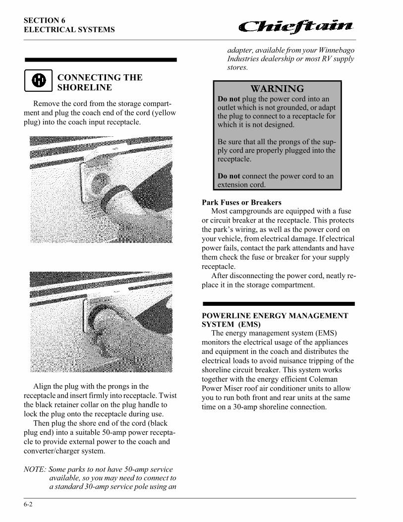
SECTION 6ELECTRICAL SYSTEMS
6-2
CONNECTING THE SHORELINE
Remove the cord from the storage compart-ment and plug the coach end of the cord (yellow plug) into the coach input receptacle.
Align the plug with the prongs in the receptacle and insert firmly into receptacle. Twist the black retainer collar on the plug handle to lock the plug onto the receptacle during use.
Then plug the shore end of the cord (black plug end) into a suitable 50-amp power recepta-cle to provide external power to the coach and converter/charger system.
NOTE: Some parks to not have 50-amp service available, so you may need to connect to a standard 30-amp service pole using an
adapter, available from your Winnebago Industries dealership or most RV supply stores.
Park Fuses or BreakersMost campgrounds are equipped with a fuse
or circuit breaker at the receptacle. This protects the park’s wiring, as well as the power cord on your vehicle, from electrical damage. If electrical power fails, contact the park attendants and have them check the fuse or breaker for your supply receptacle.
After disconnecting the power cord, neatly re-place it in the storage compartment.
POWERLINE ENERGY MANAGEMENT SYSTEM (EMS)
The energy management system (EMS) monitors the electrical usage of the appliances and equipment in the coach and distributes the electrical loads to avoid nuisance tripping of the shoreline circuit breaker. This system works together with the energy efficient Coleman Power Miser roof air conditioner units to allow you to run both front and rear units at the same time on a 30-amp shoreline connection.
WARNINGDo not plug the power cord into an outlet which is not grounded, or adapt the plug to connect to a receptacle for which it is not designed.
Be sure that all the prongs of the sup-ply cord are properly plugged into the receptacle.
Do not connect the power cord to an extension cord.

6-3
SECTION 6ELECTRICAL SYSTEMS
Please read your Power Line Energy Manage-ment System Owner’s Guide for important information on running both front and rear roof air conditioner units at the same time. This guide will also explain how this system operates under several conditions, whether 20-amp, 30-amp or 50 amp connections.
POWER CONVERTER SYSTEM
The power converter changes 110-volt AC current from the auxiliary generator or the shore-line into 12-volt DC current for use by 12-volt equipment in the motor home.
Certain circuits, however, remain unchanged for use by items which require 110-volt current, such as the air conditioner(s), the refrigerator in AC mode, the microwave oven, etc.
Current drawn from the coach batteries passes through the power center unchanged, although it is routed through a series of protective circuit breakers located on the house 12-volt and 110-volt breaker panels.
NOTE: The converter will not change 12-volt DC current to 110-volt AC.
If your coach is equipped with a DC-AC power inverter, the converter does not function while the inverter is being used.
Power Converter and Circuit Breaker Loca-tions
The converter system is made up of individual components located in various parts of the coach.
� Converter Unit: located in an exterior base-ment storage compartment. It may be located behind a protective plastic cover.
NOTE: The converter unit is replaced by the op-tional 1500W inverter/charger if your coach is thus equipped. See “1500W In-verter/Charger” on page 6-4.
� House�12-Volt Circuit Breaker Panel: behind small cabinet door below refrigerator; contains pop-out circuit breakers
� 110-Volt Breaker Panel: behind access door on the lower aisle side wall near the bath-room.
WARNINGDo not store anything around or on top of the converter, or in front of the cover. The converter generates heat while operating, and needs unre-stricted air flow for proper cooling.
House 12-Volt Breaker Panel

SECTION 6ELECTRICAL SYSTEMS
6-4
110-Volt Circuit BreakersThe breaker panel protects all 110-volt com-
ponents in the motor home from either an over-load on the circuit or a short in the wiring or component itself. When an overload or short develops, the breaker will open preventing any further flow of electricity and, therefore, damage to the system.
Shut off the equipment (example: air conditioner) and allow a brief cooling period. Then reset the breaker by moving the switch to “Off” and back to “On”. If the breaker is continually tripped and no overload is evident, have the system checked for a short in the wiring or the appliances..
Charging SectionThe converter charges house batteries while
110-volt external power is connected. The con-verter will automatically “sense” the condition of the RV battery. If it is below “full charge”, the Charging Section will start charging the battery.
If the house batteries have been extremely dis-charged, they will accept charge at a relatively high amperage rate. If they are only slightly dis-charged, they will charge at a lower amperage rate. The rate of charge will decrease as the bat-teries reach “full charge”, then will remain “trickle” charging at a very low amperage rate. If your storage battery does not charge as described above, it is possible the battery is defective.
Converter Overload ProtectorThe converter overload protector will shut-
down the converter if it becomes overheated. This can result from operating above its maxi-mum limit for an extended period of time or by obstruction of ventilation to unit.
NOTE: When the converter is not operating, 12-volt lights and motors will draw power from the house batteries.
The converter overload protector will reset it-self after a cool-down period. The lights and motors will resume operating from the converter. If the overload protector trips again shortly after reset, take immediate steps to correct cause of overheating. A portion of RV 12-volt load (lights or motors or both) should be turned off to reduce total load. Also, inspect power converter section to make sure ventilation is not obstructed.
NOTE: The converter will not change 12-volt DC current to 110-volt AC.
Further InformationRefer to the converter manufacturer’s infor-
mation provided in your InfoCase for additional information about your power converter system.
110-VOLT RECEPTACLES (Outlets)
A number of standard AC electrical outlets are provided throughout the coach for connecting small appliances such as televisions, radios, toasters, etc. Outlets are also located on the out-side of the coach near the entrance door.
GROUND FAULT CIRCUIT INTERRUPTER
Exterior, bath and galley outlets are connected to a GFCI (Ground Fault Circuit Interrupter), which is an extremely sensitive circuit breaker that will help to protect against severe electrical
House 110-volt Breaker Panel

6-5
SECTION 6ELECTRICAL SYSTEMS
shock if a ground fault develops. If such a condi-tion occurs, the GFCI will break the circuit by turning off the power to the protected outlets. Should this occur, unplug all the appliances on that circuit and press the reset button on the GFCI equipped outlet.
If the GFCI keeps tripping, have the electrical system checked and repaired if necessary before using again.
The GFCI outlet is located in the bath, bed-room or dinette area, depending on the floor plan of the vehicle.
NOTE: In compliance with CSA electrical codes, the appliance outlet in Canadian equipped coaches is not connected to a GFCI protected circuit.
AUXILIARY 110-VOLT GENERATOR Optional
Consult the generator manufacturer’s infor-mation provided in your InfoCase for instruc-tions on operation, troubleshooting and maintenance.
This coach may be equipped with one of sev-eral models of generators. Consult the generator owner’s manual in your InfoCase for specific in-structions on starting, stopping your generator
NOTE: Gasoline powered or diesel powered generators draw their fuel from the main chassis fuel tank. LP gas powered gener-ators draw fuel from the LP gas tank. Af-ter extensive generator use, you may notice decreased levels in the affected fuel tank.
Automatic Power Transfer SwitchYour coach electrical system is equipped with
an automatic power transfer switch. The transfer switch is normally connected to the shoreline cord.
When the generator is started, the transfer unit will switch the power feed to the generator after 20 seconds. The twenty-second delay is to allow the generator to start easily without an electrical load.
When the generator is shut down, power is automatically switched back to the shoreline cord.
STARTING AND STOPPING THE GENERATOR
This coach may be equipped with one of the several models of generators. Consult the gener-
WARNINGThe GFCI will not completely elimi-nate electrical shock. Small children and persons with heart conditions or other disabilities which make them especially sensitive to electrical shock may still be injured by a 110-volt receptacles even though pro-tected by a Ground Fault interrupter.
RESETTEST
WARNINGCareless handling of the generator and electrical components can be fa-tal.
Never touch electrical leads or appli-ances when your hands are wet, or when standing in water or on wet ground.
Do not attempt to repair the generator yourself. Service should be performed by an authorized service center.
Do not plug the power cord into the generator receptacle while the genera-tor is running.

SECTION 6ELECTRICAL SYSTEMS
6-6
ator owner’s manual in your InfoCase for spe-cific instructions on starting and stopping your generator.
NOTE: Gasoline powered or diesel powered generators draw their fuel from the main chassis fuel tank. LP gas powered gener-ators draw fuel from the LP gas tank. Af-ter extensive generator use, you may notice decreased levels in the affected fuel tank.
Basic Generator Operation:Starting:
For your convenience, generator switches are located on the dash, on the range hood, and on a nightstand cabinet in the bedroom as well as on the genset unit itself in the generator compart-ment. The generator starter circuit does not rely on the automotive battery, so the switch will op-erate whether the ignition switch is on or off.
� See generator manufacturer’s operating in-formation for specific instructions.
� Reduce all electrical loads. (Shut off lights, fans, appliances, etc.)
� If the generator has not been run for two weeks or more, you may need to prime the fuel system before attempting to start.
� Press the generator starter switch on and hold until generator engine is running, then re-lease.
� Let the generator engine stabilize and run smoothly before turning appliances or electri-cal equipment on.
� Do not overload generator by turning too many items on. Overloading will cause the circuit breaker on the generator to trip. If this happens, the generator will run but no elec-tricity will be present in the coach. You must then reset the circuit breaker on the side of the generator.
� Refer to the output specifications of your generator in the generator manufacturer’s manual. Then see the following electrical load chart to estimate your typical loads.
Stopping:
� Before shutting generator down, turn off electrical loads and let engine run at no-load for a few minutes to cool down.
� Press the generator switch Off and hold until the generator engine comes to a complete stop.
GENERATOR HOURMETER (If Equipped)This meter is located on the monitor panel. It
registers the total number of hours that the gen-erator has been operated. Refer to the hourmeter
Generator Switch Hourmeter
CAUTIONContinuous generator overloading can cause high operating tempera-tures that can damage the generator windings. Keep the electrical loads within the generator wattage ratings.
Approximate Power Requirements ofCommon Appliances
Appliance or Tool Approximate Power Consumption(Watts/Amps)
Vacuum cleanerCoffee MakerHair dryerElectric clothes ironElectric blanketTelevisionElectric drillAir conditionerConverterMicrowave Oven
200-500W/1.7-4.3A550-700W/4.8-6.1A800-1500W/7.0-13.0A500-1200W/4.3-10.4A50-200W/0.4-1.7A80-100W/0.7A250-750W/2.2-6.5A1400-2000W/13-19A300-500W/2.6-4.3A700-1500W/6.0-13.0A

6-7
SECTION 6ELECTRICAL SYSTEMS
to determine when periodic maintenance is due and to record services which have been per-formed.
NOTE: While the generator is running it is nor-mal for the hourmeter to make a periodic “ticking” sound.
OPERATION WARNINGS AND CAUTIONS
1. Do not simultaneously operate the generator engine and a ventilator which could draw exhaust gases into the vehicle.
2. Do not open windows or ventilators on the end or side of the vehicle where exhaust pipe of the generator is located.
3. Park the vehicle so that the wind will carry the exhaust away from the vehicle. Also, note the position of other vehicles to be sure their exhaust will not enter your vehicle.
4. Do not operate the generator engine when parked if vegetation, snow, buildings, vehi-cles, or any other object can deflect the exhaust under or into the vehicle.
Check auxiliary generator oil level frequently during periods of use. Refer to the generator manufacturer’s information in your InfoCase for specific recommendations.
12-VOLT DC SYSTEM
The DC voltage system consists of the chassis battery and the 12-volt auxiliary batteries.
Chassis (Starting) BatteryThe chassis battery is used solely to operate
the engine starter and all automotive accessories and controls found on the instrument panel. This includes the horn, speed control, all exterior lights, radio, windshield wipers, rear auto heater fan, etc.
House BatteriesThe house batteries supply current to all 12-
volt equipment located in the living area of the motor home. This includes interior lights, range exhaust fan, furnace fan, water pump, water level and holding tank gauges, 110-volt generator starting, refrigerator and bath roof vent fan. The house battery may also be used to start the engine if the automotive battery is dead. Refer to “Aux. Start Switch.”
The house batteries are automatically charged by the engine alternator when the engine is running.
House 12-Volt Circuit BreakersAll 12-volt circuits and equipment in the
coach (house) area of the motor home are protect-ed by a circuit breaker panel. When a circuit is overloaded or a short develops in any part of the system, a breaker will shut down that circuit. If this happens, turn off all affected lights or appli-ances and reset the breaker.
WARNINGThe exhaust of all internal combus-tion engines contains carbon monox-ide (CO). This poisonous gas is colorless, odorless, tasteless, and lighter than air. The exhaust systems of both your motor home engine and your generator engine have been installed with your safety in mind. However, certain precautions must be taken when using them to protect yourself from conditions beyond the control of the manufacturer.
Generator Switch Hourmeter
WARNINGNever check generator oil level while generator engine is running.

SECTION 6ELECTRICAL SYSTEMS
6-8
A label on the panel states the amperage rating and circuit protected for each breaker.
The house breaker panel is mounted behind a small door, below the refrigerator.
12-Volt Automotive Circuit Breakers and Fuses
The 12-volt automotive circuit breakers and fuses are located on a panel on the firewall beneath the left side of the dash, ahead of the driver’s left foot while seated in the driver seat. To remove the protective cover, turn the twist lock to the left, then pull the cover outward and up.
SOLAR CHARGER PANEL - Optional
Your coach is pre-wired for adding a roof mounted solar charger panel if your coach is not already equipped with this option. Because the 2-pin snap connectors are designed to connect the optional solar panel and charge indicator, we recommend that you obtain the correct compo-nents from your Winnebago Industries autho-rized dealer. (Panel: Winnebago P/N 115504-01-000/ Indicator: P/N 115505-01-000)
See your dealer for proper installation.
SOLAR CHARGER PANEL - Optional
The 10-watt roof-mounted solar charger panel uses the sun to help keep your batteries charged. A charger indicator light is located on a
cabinet wall in the galley area near the dinette table and thermostat or range hood monitor panel.
The light will glow red when the solar panel is charging the coach batteries. The greater the rate of charge, the brighter the light. When the batteries reach full charge the light will gradu-ally dim, then darken.
NOTE: The solar battery charger is not intend-ed to make the coach battery system “maintenance free.” The solar panel will not completely compensate for continu-ous low amperage draw from compo-nents such as the LP gas leak detector, the clock in the dash radio and the radio station memory circuitry, for example.Although the solar panel system can help to extend battery life, the coach shoreline should be plugged in routinely to “top off” the batteries. We also recommend following regular battery inspection and maintenance, especially in cold weather.
BATTERY INFORMATION
The coach batteries are “deep-cycle” type bat-teries specially designed for recreational vehicle use. They will provide longer lasting power than standard automotive batteries, and will withstand the frequent drain-and-recharge cycles that occur

6-9
SECTION 6ELECTRICAL SYSTEMS
under the demanding conditions of a camping outing.
BATTERY ACCESSThe batteries are located beneath the top en-
trance step. Unhook the latch assembly fastening the top step and remove.
*NOTE: The chassis batteries for models on Freightliner diesel chassis are located in a compartment on the left side of the ve-hicle to the rear of the rear wheels. Two coach batteries are standard.
BATTERY MAINTENANCE
Lead -acid type batteries are electro-chemical devices for storing and releasing electrical charge. As such, they are simply an electrical res-ervoir, not an electrical source. As soon as energy is removed from the battery, it should be replaced by the engine alternator or the RV converter sys-tem.
If a battery sits unused for 30 days or more, especially during warm weather, it can develop a deposit of sulfate crystals on the metal plates in-side the battery. This conditions is called sulfa-tion or sulfating, and prevents the battery from either releasing or accepting a charge. If this con-dition occurs, the battery must be replaced.
If a battery does not contain at least 80% charge during freezing temperatures, the electro-lyte can freeze and crack the battery case.
The two best defenses against sulfating and insufficient charge are to:1) turn off the Auxiliary Battery switch to avoid parasitic discharge (the trickle discharge caused by directly connected components like LP gas detectors or digital clock displays in the range hood or radio, etc.), and2) check the battery and recharge as necessary at least once a month during long storage periods.
Turn the Aux. Batt. Switch off to avoid elec-trical arcing when attaching or detaching charger clamps.
NOTE: We do not recommend leaving the shore-line plugged in continuously during stor-age periods because the batteries can lose electrolytic fluids and become dam-aged from continuous charging without periodic use. We recommend following regular battery inspection and mainte-nance, especially in cold weather.
Futher precautions are:� Remove the battery from the coach.
� Store it in a cool place on a wooden or rubber pad to inhibit conductive transfer.
� Check the state of charge periodically to avoid discharge or sulfating.
� Make sure the batteries always remain se-curely clamped in the battery tray.
� Make sure battery cable clamps are tight on the terminal posts and are free of corrosion.
� Neutralize corrosion buildup or acid film on top of battery by washing with a baking soda/water solution. Rinse with clear water.
NOTE: Make sure vent caps are on securely to prevent baking soda solution from enter-ing the battery and contaminating the electrolyte fluid.
Coach Batteries
ChassisBattery
Removable Step
Latch
Battery Compartment(Inside Entrance Step)
Chassis*Battery

SECTION 6ELECTRICAL SYSTEMS
6-10
� Clean and tighten battery terminals and have the specific gravity checked at least once a year.
� Every two months, or more often in hot weather, check the battery fluid level. If nec-essary, fill with distilled water to approxi-mately 3/8 inch above the plates. DO NOT OVERFILL. If water is added during freez-ing weather, either charge the battery or drive the motor home several miles to mix water and electrolyte to prevent freezing.
� Fluid level check may be omitted if equipped with maintenance-free batteries.
BATTERY CONDITION METERSee related item under “Monitor Panel” in sec-
tion 8, Appliances.
AUX. START SWITCHSee section 2, Driving Your Motor Home for
information on Aux. Start Switch.
TRAILER WIRING CONNECTORYour coach is pre-wired for trailer or car tow-
ing lights with a 6-pin socket on the rear bumper. The connector plug is supplied in the coach parts package provided to you by your dealer when you took delivery of the vehicle.
The diagram shows proper connection of trail-er or tow vehicle wiring to the coach light system. Remove the small screw near the end of the plug and slide the contact assembly out of the barrel.
*NOTE: On Ford chassis, these turn signal con-nection also include a brake light func-tion.
WARNINGBefore removing any battery cables or battery, make sure all 12-volt equip-ment in the motor home is off and the power cord has been disconnected.
Replace any damaged cables at once. Always remove jewelry and wear pro-tective clothing and eye covering when checking or handling batteries.
WARNINGTo prevent wiring damage, it is essential when replacing the cables on the battery, or when using a “booster” battery, that the positive post and the positive cable be attached and the negative post and negative cable be attached. The posts are marked (+) plus and (-) minus. If a “fast charger” is used while battery is in the motor home, disconnect both battery cables before connecting the charger. Never attempt to charge or boost a frozen battery.
TM = Tail lightsGD = GroundLT = Left TurnRT = Right TurnS = Brake lightsA = Backup lights
TM = Tail lightsGD = GroundLT = Left Turn*RT = Right Turn*S = Brake lightsA = Backup lights

SECTION 7PLUMBING SYSTEMS
7-1
FRESH WATERSYSTEM
The fresh water system provides water to the galley sink, shower, bathroom lavatory, toilet and water heater. Water may be supplied by either of two sources:� a water tank located within the motor home,
or.� any external water source to which the motor
home may be connected, known as “city wa-ter”.
FILLING THE FRESH WATER TANK:Always fill the fresh water tank at an approved
potable water filling facility or a known purified drinking water source.
You can fill your water tank using either of two methods; gravity fill or city water pressure fill.
Gravity Fill: Insert hose into fill opening and turn water supply on. Tank is full when water flows from overflow tube beneath coach. The gravity fill tube is located behind a small, lock-able door on the right (passenger) sidewall to-ward the back of the coach.
City Water Pressure Fill: Attach hose to city water connector. Turn fill valve to “Water Tank Fill”, then turn city water supply on. Tank is full when water flows from gravity fill tube. The city water connector is located in the utility system compartment on the left (driver) side of the coach.
NOTE: Because city water pressure varies from location to location, we recommend us-ing an in-line water pressure regulator to prevent damage to any components, connections and seals in your fresh wa-ter system.
A water pressure regulator may be ob-tained from any well stocked RV dealer-ship retail center and some retail discount centers. These devices simply connect in-line between the supply hose and the city water input on the coach.
We recommend a regulator that controls water pressure to 40 psi maximum.
NOTE: Be sure to open the gravity fill door to prevent pressure build up while filling the tank from the city water connector.
NOTE: Always keep the tank fill valve pointed to “City Water” unless you are filling the tank. If this valve is pointing to “Water Tank Fill” while using city water, the water will keep flowing into the tank and out the gravity fill tube.
WATER TANK F ILL
Fresh Water Tank Capacity
Model 33B ...........................................70 gal.Model 36L (Freightliner chassis).........86 gal.Models 34Y, 35C, 35U & 36L (Chevy/Ford chassis) .......................92 gal.

SECTION 7PLUMBING SYSTEMS
7-2
WATER PUMP
Pressure for the water system is supplied by a water system demand pump which is fully auto-matic after initial priming. When a faucet is opened, the pump begins operation to provide a constant flow from the tank. When the faucet is closed, the pump automatically shuts off.
Water Pump SwitchYour coach is equipped with water pump
switches in three convenient locations:� on the range hood monitor panel (See section
8)� in the bathroom� in the exterior shower compartment on the
outside of the coach (See page 7-4).
Initial Start-Up1. Make sure that all water drain valves are
closed, including water heater valve. (Refer to Section 10.)
2. Turn water pump switch to “OFF” position.3. Fill water tank.4. Open all faucets, hot and cold.5. Turn on pump switch.6. Close each faucet as it begins to deliver a
steady stream of water (close cold water first). Leave hot water faucets on until they also deliver a steady stream of water. This will ensure that the water heater is filled with water.
7. Check to be sure pump stops soon after all faucets have been closed.
8. Pump is now ready for automatic operation. Pump will start when a faucet is opened and stop when the faucet is closed.
ACCUMULATOR TANKA pressurized accumulator tank is installed in
the water line directly upstream from the water pump located in the rear compartment on the driver or passenger side of the coach.
The accumulator tank holds a small amount of water under pressure of 20 psi to reduce water line pulsation noise and pressure variations when using the water pump system. This also contributes to longer pump life, less pump cycling, and less amperage draw by the water pump from the coach batteries.
NOTE: The accumlator tank has a precharge pressure which must be checked monthly and maintained at 20 psi for the system to work properly.
Adjusting Precharge PressureA tire-type valve stem is provided on the end
or top of the accumulator tank to check or add air pressure.
When adding air, do not exceed 20 psi tank precharge pressure because you may risk ruptur-ing the pressure bladder inside the accumulator tank. Before checking precharge pressure, drain the accumulator tank by turning off the water pump and opening a faucet to drain off water

7-3
SECTION 7PLUMBING SYSTEMS
line pressure. Because of the relatively small capacity of the bladder, check pressure with a standard tire pressure gauge before adding air, then if necessary, add air in small bursts, check-ing pressure between each burst until 20 psi is attained.
Overfilling will also push the bladder too far and reduce the volume of water held in the accumulator tank, making the system inefficient.
The precharge valve stem cap must be tight to prevent pressure leak-down.
Further InformationSee manufacturer’s information supplied in
your InfoCase for complete maintenance instruc-tions and precautions.
EXTERNAL WATER SUPPLY (“City Water”)To connect to an external source:
1. Turn the demand pump switch to Off. Also be sure fill valve is turned to “City Water” as shown
2. Attach a hose from the external water source to the city water connection in the utility compartment on the left side of your vehicle.
3. Turn on the external water source.
When connected to an outside source of water, the water bypasses the demand pump and storage tank and supplies pressure directly to individual faucets and toilet. A check valve built into the pump prevents water from entering the pump and filling the storage tank.
To disconnect from the external source:1. Turn the external source off.2. Open a faucet inside the vehicle to relieve
line pressure.3. Disconnect the hose from the coach.4. Stick your finger up inside the connection
and gently press the backflow valve upward to drain any water left in the line.
5. Replace the protective plug back into the threaded collar on the connection.
DISINFECTING FRESH WATER SYSTEMS ON RECREATION VEHICLES
(As approved by the U.S. Public Health Service)
To assure complete disinfection of your fresh water system, it is recommended that the follow-ing procedure be followed on a new system, one that has not been used for a period of time, or one that may have become contaminated. This procedure is also recommended before long periods of storage such as over winter.
1. Prepare a chlorine solution using 1 gallon of water and 1/4 cup of household bleach (sodium hypochlorite solution). With tank empty, pour chlorine solution into the tank. Use 1 gallon solution for each 15 gallons of tank capacity. This procedure will result in a residual chlorine concentration of 50 ppm in the water system. If a 100 ppm concentration is required as discussed in item 3, use 1/2 cup of household bleach with 1 gallon of water to prepare the chlorine solution. One gallon of the solution should be used for each 15 gallons of tank capacity.
2. Complete filling of tank with fresh water. Open each faucet and run the water until a distinct odor of chlorine can be detected in the water discharged. Do not forget the hot water taps.
3. Allow the system to stand at least 4 hours when disinfecting with 50 ppm residual chlorine. If a shorter time period is desired,

SECTION 7PLUMBING SYSTEMS
7-4
then a 100 ppm chlorine concentration should be permitted to stand in the system for at least 1 hour.
4. Drain and flush with fresh water.
WATER PURIFIER SYSTEM
The water purifier system uses a flow-through activated carbon filter that removes chlorine and other impurities, resulting in clean, taste-free and odorless drinking water.
Replacing the water filter cartridge: Replace the filter cartridge when water flow
from the purifier faucet is too slow for conve-nience. � Place a container beneath the filter to catch
any any remaining water during removal.� Raise the valve handle and turn the colored
ring fully clockwise.� Twist the filter cartridge counterclockwise
about a quarter-turn and pull it down and out of the filter head.
� Raise the valve handle and turn the colored ring fully clockwise.
� Insert a new water filter cartridge up into the filter head as far as possible and turn it clock-wise a quarter-turn.
� Turn colored ring fully counterclockwise to lock the filter cartridge in position between the head and colored ring.
� Lower valve handle to lock colored ring in place.
See “Winterizing the Water Purifier System” in Section 10.
SHOWER HOSE VACUUM BREAKERAfter using the shower, you may notice water
dripping from the shower faucet assembly. The dripping results when vacuum in the shower hose (after closing the shower faucet) slowly releases and allows water remaining in the hose to drain down. This is a normal function of the shower valve assembly and is not a leak or defect.
The International Association of Plumbing and Mechanical Officials Standard TSC 21-85 (PAR. 4.3) states:
“Shower heads which incorporate shutoff valves, shall have a minimum “drip rate” of one (1) quart in thirty (30) minutes.”
The label shown below is attached on or near the faucet to explain the operation of the vacuum breaker assembly.
WARNINGChlorine is poisonous - recap bottle and clean utensils after use.
Never use automotive type antifreeze in your potable water system as it is poisonous.
Water Filter Assembly - Below Galley Sink
CAUTIONIf items are placed into the shower tub before shower valve vacuum release is complete, they may become wet.

7-5
SECTION 7PLUMBING SYSTEMS
EXTERIOR SHOWER
The exterior auxiliary shower feature allows you to do things such as rinse off sand or salt after a swim, rinse off muddy boots, or bathe your pet outside the coach. It is located in the utility sys-tem compartment.
For your convenience, a water pump switch is located near the shower knobs. This allows you to turn the pump on or off from outside the coach.
The exterior shower also doubles as a water line drain valve. See drain valve locations on page 7-8 for further information.
WASTE WATER SYSTEM(HOLDING TANKS)
The drainage system is self-contained and uses two separate holding tanks to contain the waste water until it can be dumped at an appro-priate waste water disposal site. This means you can use the toilet, sinks and shower even in areas where utility hookups are not available.
The main holding tank contains the sewage from the toilet, and is commonly called the black water tank. The second holding tank contains the waste water from the galley sink, bathroom lava-tory and shower, and is commonly called the gray water tank.
The holding tanks are dumped through a com-mon outlet located inside the utility compartment on the left side of the coach, ahead of the rear wheels.
DUMPING HOLDING TANKS1. Remove drain hose from exterior storage
compartment.2. Remove dust cap from drain and connect
drain hose. Be sure it is firmly attached.3. Place the other end of sewer hose into dis-
posal opening.4. Open the the black water valve with a quick
pull and make sure there are no sags in the hose. Move the hose gently about to dislodge any waste and ensure complete drainage. Close black water valve as soon as tank is empty.
NOTE: Do not open the gray water valve until the black water tank is drained and dump valve closed to avoid sewage back-up into gray tank. Gray water also rinses any black water solids from the drain hose.
For your protection, this faucet is equipped with a vacuum breaker (back flow preventer) to prevent contamination of your potable wa-ter supply. The water in the hand held shower hose will drain through this vacuum breaker when the faucet is turned off. This is not a leak. This drainage is inherent in the design of the vacuum breaker, and is evidence that it is functioning properly.
P.P.I. 0387

SECTION 7PLUMBING SYSTEMS
7-6
5. Open the gray water valve. Be sure there are no sags in the hose to ensure complete drain-age. Close gray water valve as soon as tank is empty.
6. After both tanks have been drained, run sev-eral gallons of water into the sewage tank through the toilet. Then open sewage dump valve and drain the tank again. Close valve and replace dust cap securely.
7. It is advisable to add an odor control chemi-cal to the sewage holding tank. These chemi-cals are available at most R.V. stores.
8. Rinse sewer hose thoroughly with water and stow.
NOTE: We recommend that you dump all hold-ing tanks before traveling to avoid carry-ing unnecessary weight.
Flushing your Black Water Holding Tank
The black water holding tank is equipped with an internal flushing head to allow you to rinse the inside of the tank with clean water after dumping.
1. Dump your black water holding tank in the usual manner at approved sewage disposal station.
2. Leave black water dump valve open while flushing tank.
3. Attach a garden hose from a city water
hydrant to the Flushing System inlet fitting near the black water dump valve. (This inlet is clearly marked separate from the City Water inlet.)
4. Turn the water on to begin flushing; allow water to run for about three minutes.
5. Disconnect hose from flushing system fitting and close dump valves.
USING ON-SITE SEWER HOOK-UPSThe drain hose may remain attached to the
dump outlet and be routed out the bottom of the compartment while the motor home is parked and connected to an on-site sewage hook-up.
When using a sewer hook-up, keep the dump valves closed until a tank becomes full or when preparing to leave the site. This keeps the solids in suspension, allowing them to be carried out with the liquids when the dump valve is opened. If the valve is left open, the liquids will drain off, leaving solids in the tank. Should this accidental-ly happen, disconnect the hose, fill the tank about half full with water, and drive a few miles to dis-lodge the solids. A few starts and stops will aid in the process. Then reconnect the hose and drain in the normal manner.
UTILITY LIGHTA lamp is located up on the left sidewall to
provide light in the utility hook-up area.The switch is located inside the utility system
compartment on the left side of the coach.
HOLDING TANK LEVEL INDICATORSThe holding tanks may be monitored on the
wall mounted monitor center.
Black WaterTank Flush Inlet

7-7
SECTION 7PLUMBING SYSTEMS
Press the “Levels Test” switch to check the level in each tank.
See pages 8-8 for further information on the monitor panel.
WATER DRAIN VALVESThe water drain valves are used to drain water
from the water tank and the water supply lines when preparing the motor home for storage or when sanitizing the water system.
To open or close the drain valves, turn the handles in the directions indicated by the follow-ing illustration.
Drain valve locations are listed on the follow-ing pages.
Models built on Freightliner diesel pusher chassis: The tank drain valve is operated by a remote cable/handle labeled and located near the sewage drain valve handles.
DRAIN DRAIN
CLOSE CLOSE
IN-L INE VALVE
L INE-END VALVE
Water Tank Drain Valve - Model 36WL Freightliner Diesel
TANK CAPACITIESHT1 - Black Water Holding TankModels 33B, 34Y & 36L (Toilet) .............................................................................................. 55 gal.Models 35C & 35U (Toilet) ....................................................................................................... 40 gal.
HT2 - Gray Water Holding TankModels 33B, 34Y & 36L (Galley, Shower & Lavatory)............................................................ 55 gal.Models 35C & 35U (Galley, Shower & Lavatory) ................................................................ TBD gal.

SECTION 7PLUMBING SYSTEMS
7-8
WATER SYSTEM DRAIN VALVE LOCATIONSMODEL SYSTEM DRAIN VALVE LOCATIONS
33B34Y
Water Lines:
Water Tank:
Water Heater:
Water Heater By-Pass Valve:
Winterization(Antifreeze) Valve:
Hot and Cold water lines: One (1) valve near the water tanks in the rear cargo compartment on the passenger side of the coach. Open exterior shower faucet valves and lay shower head on ground to drain exterior shower line. Also the tip of your finger inside the city water connection and gently press the backflow valve (small “button” in center of connector) to drain any water left in the city water line.
One (1) valve near the water tank in the rear cargo compart-ment on the passenger side of the coach.
Drain plug on outside of coach, behind service door. Use socket to remove drain plug.
Located behind a removable black access panel beneath the galley sink cabinet.
Near the water tanks in the rear cargo compartment on the passenger side of the coach.
35C35U
Water Lines:
Water Tank:
Water Heater:
Water HeaterBy-Pass Valve:
Winterization (Antifreeze) Valve
Hot and Cold water lines: One (1) valve near the water tanks in the rear cargo compartment on the passenger side of the coach. Open exterior shower faucet valves and lay shower head on ground to drain exterior shower line.Also place the tip of your finger inside the city water con-nection and gently press the backflow valve (small “button” in center of connector) to drain any water left in the city water line.
One (1) valve near the water tank in the rear cargo compart-ment on the passenger side of the coach.
Drain plug on outside of coach, behind service door. Use socket to remove drain plug.
Model 35C: In bottom of passenger side rear wardrobe cabi-net, beneath removable bottom panel.Model 35U: In bottom of driver side rear nightstand. Access through trunk compartment
Near the water tanks in the rear cargo compartment on the driver side of the coach.

7-9
SECTION 7PLUMBING SYSTEMS
36L Water Lines:
Water Tank:
Water Heater:
Water HeaterBy-Pass Valve:
Winterization (Antifreeze) Valve
Hot and Cold water lines: Valves located in water/drainage compartment on driver side of coach. Open exterior shower faucet valves and lay shower head on ground to drain exterior shower line. Also place the tip of your finger inside the city water connection and gently press the backflow valve (small “button” in center of connector) to drain any water left in the city water line.
Valve located in water/drainage compartment of driver side of coach. Chevy or Ford chassis: Turn the valve knob as shown in the previous illustration. Freightliner diesel chassis: Pull out small T-handle valve in water/drainage compartment. Push handle back in to close valve as soon as tank is drained.
Drain plug on outside of coach, behind service door. Use socket to remove drain plug.
Under galley sink cabinet.
In the middle cargo compartment on the passenger side of the coach.
To properly winterize the shower, you must drain the line which runs from the shower faucet valves to the corner spout. A drain valve is located behind the vent panel in the aisle side of the shower base cabinet. Remove the screws to remove the vent, then turn the valve as shown in the illustra-tion.


SECTION 8APPLIANCES & INTERIOR FEATURES
8-1
(See also Safety Precautions, Section 1 of this manual.)
NOTE: Because this model is available in sever-al sizes and floor plans, some items de-scribed may be optional or unavailable on your coach.
The appliances installed in your motor home are manufactured by reputable RV appliance makers and have been tested by independent lab-oratories to meet all applicable standards and codes set for RV appliances. These appliances are covered by your New Vehicle Limited War-ranty. (Certain items may be covered by individ-ual manufacturer’s warranty.) See your New Vehicle Limited Warranty for details.
REFRIGERATOR
The refrigerator in your coach can be operated from either of two power sources available to the motor home:� 110-Volt AC electric� LP gas
The refrigerator is an absorption type which uses an ammonia-water solution for cooling. Basically, ammonia vapor is distilled from the solution by heat, produced from either LP gas or electricity and then carried to the finned condens-er where it liquefies. The liquid then flows to an evaporator where it creates cold temperatures through evaporation.
LEVELINGBefore operating the refrigerator when the
motor home is stationary, place a small level on the freezer plate and make certain the unit is level.
Normal vehicle leveling to provide comfort for the occupants is satisfactory for refrigerator operation. This will be well within the operation limits of 3� off-level side-to-side and 6�off-level front-to-back.
OPERATING INSTRUCTIONSNorcold Model 900-Series Models with Elec-tronic Auto Mode Control
Start-Up Instructions - Gas ModeThe control panel is located between the
freezer compartment and fresh food compart-ment. It contains pressure sensitive touch switches and LED display. The AC, LP GAS, Battery, and AUTO LED’s (A) illuminate to indicate the refrigerator’s operating mode.
The ON/OFF button (E) turns the refrigera-tor On or Off. If the button is pressed, it will turn the refrigerator On and set the mode to AUTO. When the refrigerator is On, pressing this button for 2 seconds will turn the refrigerator Off.
Pressing and holding the MODE button (C) allows the user to cycle through the three mode choices; one AUTO and two manual modes (AC, LP GAS). The refrigerator will not switch to the new operating mode until the mode button is released.
CAUTIONTo prevent permanent damage to the refrigerator cooling unit, turn the refrigerator off if the vehicle will be parked on an incline of over 3� side-to-side or 6� front-to-rear (such as steep driveways or parking lots, etc.) for more than one hour.

SECTION 8APPLIANCES & INTERIOR FEATURES
8-2
The TEMP SET (thermostat) button (D) con-trols the refrigerator and freezer temperature during both gas and electric operation. Press and hold the TEMP SET button to select the desired temperature setting. The temperature settings are shown in the form of LED’s (A). The illumi-nated LED indicates the temperature setting, with COLD on the left and COLDEST on the right. The temperature LED turns off after 10 seconds. Quickly press and release tempset but-ton to display the temperature setting.
Start-Up Instructions - Auto ModeWhen the AUTO mode is selected, the oper-
ating control automatically selects the power source using the following priority scheme:• When 120 volts AC is available to the refrig-
erator, the AUTO LED and the AC LED will illuminate, indicating the refrigerator is oper-ating on AC electric.After 10 seconds, the AC LED will turn off and only the AUTO LED will remain illuminated. Press and quickly release mode button to display the operating mode.
• If 120 volts AC is not available, the refriger-ator will switch to the gas operation. The AUTO LED and the LP GAS LED will illu-minate. After 10 seconds, the LP GAS LED will turn off and only the AUTO LED will remain illuminated. Press and quickly release mode button to display the operating mode.
During operation in the AUTO mode, when a higher priority power source becomes avail-able, the operating controls will cease using the current power source and will switch to the higher priority power source. For example, if AC electric becomes available while the refrig-erator is operating in the AUTO LP GAS mode, the refrigerator will switch to AUTO AC opera-tion.
If an operating mode is not functional, its corresponding LED will flash and the refrigera-tor will attempt to operate in a lower power pri-ority source. If a lower power priority source is not available, the LED will continue to flash, and the refrigerator will cease operation until the
energy source is corrected. Refer to the “Diag-nostic” section on page 7 of the “Norcold 9100 Series Refrigerators Operator’s Guide” in your InfoCase.
Start-Up Instructions - Manual Mode
To operate the MANUAL mode, press and hold the MODE button (C) until the AUTO LED disappears and the desired operating mode is displayed. If the power source is interrupted while operating in the MANUAL mode, the AUTO LED disappears and the desired operat-ing mode is illuminated. Unlike AUTO mode, the operating mode LED remains illuminated until an alternate mode is selected. If the energy source is interrupted while in the MANUAL mode, the corresponding LED flashes, and the refrigerator ceases operation until an alternative energy source is selected or the problem is cor-rected. Refer to the “Diagnostics” section on page 7 of the Norcold Operator’s Guide in your InfoCase for corrective actions.
AUTO and MANUAL Modes - Gas Operation Only
If the gas does not ignite within 30 seconds, which may occur on initial start-up, the refriger-ator’s gas valve will automatically close and the operating controls will select an alternate power source (AUTO Mode) or revert to a stand-by mode in which the LP GAS LED flashes. The LED continues to flash until the refrigerator is turned OFF and then ON. If the gas does not ignite after several attempts, check the input gas supply, or consult with your dealer or a Norcold authorized service center. A different mode of operation may be selected by pressing and hold-ing the MODE button. The refrigerator will not switch to the new operating mode until the MODE button is released.

8-3
SECTION 8APPLIANCES & INTERIOR FEATURES
Backup Operating System (“BOS”)Your refrigerator features a Backup Operat-
ing System which keeps the refrigerator cool in the event of a failure of the refrigerator’s operat-ing controls. If a failure occurs, the TEMP SET LED flashes and refrigerator switches to the BOS mode. This mode provides refrigeration until the refrigerator is serviced. The fresh food and freezer compartment temperatures should be monitored to prevent over-freezing or thawing of refrigerator contents when operating in the BOS mode. If the refrigerator temperature is too cold, adjust the thermostat to the left in single LED increments. If the refrigerator temperature is too warm, adjust the thermostat to the right in single LED increments. Let the refrigerator operate at the new setting for one hour before rechecking the freezer and fresh food compartment tempera-tures. (Frequent door opening prevents the tem-peratures from stabilizing.) Although the refrigerator can operate in this mode, Norcold recommends that you seek service to restore manual operation as soon as practical.
Operating Tips
� The refrigerator should already be cold be-fore placing items in it.
� Food and beverages should also be cold be-fore placing in RV refrigerator. Never put warm or hot items in a cold refrigerator.
� Do not pack the refrigerator too full. The re-frigerator needs room for cold air to circulate.
� Use smaller containers for each item. (e.g. a half gallon container of milk instead of a half-full gallon jug)
� Always put foods, especially liquids, in tight-ly sealed containers.
� Use crumpled paper between loose items to reduce rattling or “clinking” noises.
Further InformationFor further information and operating cau-
tions, see the Norcold refrigerator operating in-structions included either inside the refrigerator
or in your InfoCase.
How to Use the RefrigeratorFood Storage Compartment
The food storage compartment is completely closed and unventilated, which is necessary to maintain the required low temperature for food storage. Consequently, foods having a strong odor or those that absorb odors easily should be covered. Vegetables, salads, etc. should be cov-ered to retain their crispness. The coldest posi-tions in the refrigerator are under the cooling fins and at the bottom of the refrigerator. The warmer areas are on the upper door shelves. This should be considered when placing different types of food in the refrigerator.
When the refrigerator is heavily loaded, it will take a longer time to lower the temperature; therefore, to get maximum efficiency the refrig-erator and food items should be pre-cooled prior to loading. The shelves should not be covered with paper or plastic, and the food items should be arranged so air can circulate freely.
Frozen Food Storage CompartmentQuick frozen soft fruits and ice cream should
be placed in the coldest part of the compartment, which is on the top freezer shelf. Frozen vegeta-bles may be stored in any part of the compart-ment.
This compartment is not designed for deep or quick freezing of food. Meat or fish, whether
WARNINGMost LP gas appliances used in recre-ational vehicles are vented to the out-side of the vehicle. When parked close to a gasoline pump, it is possi-ble that the gasoline fumes could enter this type of appliance and ignite from the burner flame, CAUSING A FIRE OR AN EXPLOSION.
FOR YOUR SAFETY, it is recom-mended that all LP gas appliances which are vented to the outside should be shut off when refueling.

SECTION 8APPLIANCES & INTERIOR FEATURES
8-4
raw or prepared, can be stored in the frozen food storage compartment provided they are pre-cooled first in the refrigerator. They can be stored about three times longer in the frozen food compartment as compared to the fresh food compartment. To prevent food from drying out, keep it in covered dishes, containers, plastic bags or wrapped in aluminum foil.
Ice MakingIce cubes can be made in the ice trays placed
in the freezer compartment. The trays should be filled with water to within 1/4” (5 mm) from the top. For faster ice making, the trays should be placed in direct contact with the freezer shelves.
To release the ice cubes, seize the tray with both hands and twist the tray. Cubes not required should be replaced in the tray. Refill the tray with water and replace the tray on the freezer shelf.
Ice will be made more rapidly if the thermo-stat is set at its highest position.
It is a good idea to do this a few hours before the anticipated need for ice, but be sure to move the thermostat back to normal setting, usually about mid setting when the ice if formed. Food in the lower compartment may be frozen if the setting is left on “COLDEST” position.
DefrostingShut off the refrigerator by pressing the main
power ON/OFF button to the (OFF) position.Empty the refrigerator, leaving the drip tray
under the finned evaporator, and the cabinet and freezer doors open. Defrosting time can be reduced by filling the ice trays with hot water and placing them on the freezer shelves.
When all the frost has melted, dry the inte-rior of the refrigerator and freezer with a clean cloth. Replace all food and set the thermostat to the COLDEST temperature setting for a few hours. Then reset the thermostat to the desired setting, usually at mid setting.
CleaningCleaning the refrigerator is usually done after
it is defrosted or put into storage. To clean the in-terior liner of the refrigerator, use lukewarm weak soda solution. Use only warm water to clean the finned evaporator, ice trays and shelves. NEVER use strong chemicals or abrasives to clean these parts as the protective surfaces will be damaged. It is important to always keep the re-frigerator clean.
Shut Off - Storage ProcedureShut off the refrigerator by pressing the main
power ON/OFF button to the (OFF) position.If the refrigerator will not be in operation for a
period of weeks, it should be emptied, defrosted, cleaned and the doors left ajar. The ice trays should also be dried and kept outside the cabinet.
NOTE: The climate control will draw 12 volts DC power continuously when in the ON position. It should be turned OFF when a charging source is not available.
REFRIGERATOR COMPARTMENT(Exterior)
The exterior refrigerator compartment allows access to the rear of the refrigerator for inspec-tion, maintenance and service.
CAUTIONDO NOT use a hot air blower. Perma-nent damage could result from warp-ing the metal or plastic parts. DO NOT use a knife or an ice pick, or other sharp tools to remove frost from the freezer shelves. They can create a leak in the ammonia system.
CAUTIONDO NOT store explosive substances in the refrigerator, such as cigarette lighter gas, petrol, ether or the like.

8-5
SECTION 8APPLIANCES & INTERIOR FEATURES
To Open:1. Use a coin to turn the latch knobs to the ver-
tical position as shown.2. Remove the door from the opening.
To Close:1. Replace the door into the opening.2. Push the latch knobs in while turning to the
horizontal position as shown.
RANGE AND OVEN
The range and oven in your motor home are operated on LP gas and will provide nearly all of the functions that the range in your home does. One benefit of gas burners is that heat is available as soon as a burner is lit, as opposed to an electric element slowly heating up. The range has a “Pilot Off” position on the oven control which allows the oven pilot to be turned off when traveling or refilling the LP tank.
The following warning label has been located in the cooking area to remind you to provide an adequate supply of fresh air for combustion.
Unlike large homes, the oxygen supply inside a recreational vehicle is limited due to its size. To avoid danger of asphyxiation, provide proper ventilation when using the gas rangetop or gas oven. It is especially important not to use the gas oven and range top for comfort heating. Danger of asphyxiation is greater when these appliances are used for long periods of time.
Using Range Top Burners1. Rotate the Spark knob clockwise to provide
ignition spark.2. While rotating the Spark knob, turn the
selected Burner knob to ON.3. When the burner lights, release the Spark
knob and turn the Burner knob to adjust the flame height.
Refrigerator Access Compartment
CLOSE OPENRefrigerator Access Door Latches
WARNINGPortable fuel-burning equipment including wood and charcoal grills and stoves, should not be used inside the recreational vehicle. The use of this equipment inside the recreational vehicle may cause fires or asphyxia-tion.
WARNING IT IS NOT SAFE TO USE COOKING I T IS NOT SAFE TO USE COOKINGAPPL IANCES FOR COMFORT HEAT INGAPPL IANCES FOR COMFORT HEAT ING
COOKING APPL IANCES NEED FRESH A IR FOR SAFE OPERAT ION.COOKING APPL IANCES NEED FRESH A IR FOR SAFE OPERAT ION.
BEFORE OPERAT ION:BEFORE OPERAT ION:
1 . OPEN OVERHEAD VENT OR TURN ON EXHAUST FAN AND;1 . OPEN OVERHEAD VENT OR TURN ON EXHAUST FAN AND;
2 . OPEN WINDOW.2 . OPEN WINDOW.

SECTION 8APPLIANCES & INTERIOR FEATURES
8-6
Lighting Oven Pilot
NOTE: If range has not been operated for a long period of time, a longer waiting period for ignition of the pilot may be necessary due to air in the gas line.
Operating Oven ControlPush in and turn the oven control knob (coun-
terclockwise) to the desired temperature setting.
There is a delay of about 45 seconds before the main burner ignites. This is normal and there is no gas escaping during this delay. It is also nor-mal for the oven burner flame to cycle off and on at all temperatures except broil (BR).
Shut Down InstructionsWhen oven cooking is finished, turn the oven
control knob to the “PILOT ON” position, the oven standby pilot will remain lit.
When the recreational vehicle is not in use or while traveling, turn the oven control knob to “OFF” position and turn off main gas supply; this will turn off the oven pilot.
MICROWAVE OVEN (Optional)For complete operating instructions, refer to
the manufacturer’s information provided with the oven.
RANGE HOOD AND MONITOR PANEL
The monitor panel is built into the aisle end of the galley cupboard. It provides central loca-tion of switches for the water pump switch and tank level indicators. The auxiliary electric gen-erator start/stop switch and hourmeter are also located on the monitor panel. (See section 6 for generator starting and stopping instructions and operating precautions.)
WARNINGDo not turn burner control knob to “On” and allow gas to escape before operating spark ignition or lighting match.
Oven Control Knobin "OFF" position
Oven Control Knobin "PILOT ON"position
1. Be sure all valves are in the “OFF” Position. The oven control knob should be in “OFF” position.
2. Turn on main gas sup-ply to range.
3. Press and turn control knob to the “PILOT ON” position. This will allow gas to oven pilot.
4. Open oven door and light oven pilot with a match. Small flame will be noted at the
Lighting oven pilot (when pilot islocated on left side of burner.)

8-7
SECTION 8APPLIANCES & INTERIOR FEATURES
At the push of a single button this monitor panel simultaneously displays the coach battery condition and levels of the water tank, holding tanks and LP tank. It also contains the water pump power switch and an indicator light to show when the pump switch is on.
Water and Holding Tank LevelsPress and hold the “Levels Test” switch to
show approximate level on the monitor lights.Approximate levels of the fresh water and
holding tanks are measured by sets of electronic probes in the sides of the tanks. The liquid must be at or above a probe to illuminate the indicator lights to a given level.
For example, a water level of 1-2” above the 1/3 probe would register as only 1/3 full. Conse-quently, a level of merely 1” below the 1/3 probe would register empty. Generally speaking, there is actually more liquid in a tank than indicated.
Tank CapacitiesSee back of “To The Owner” page inside
front cover of this manual.
LP Gas LevelPress and hold the “Levels Test” switch to
show approximate LP tank level.The LP level is registered by a sending unit on
the tank. The gauge mounted on the side of the tank will give a more accurate indication of actu-al tank level if needed.
Water Pump SwitchWhen use of the self-contained water system
is desired, turn the “Water Pump” switch on. The “Pump On” light will illuminate when the pump switch is on and the system is operable. Water will be available as soon as a faucet is opened. Refer to “Fresh Water System” for additional in-formation on the water pump and initial start-up.
Generator Start/Stop SwitchSee Section 6, Electrical Systems for genera-
tor start-up and shut-down instructions.
Generator HourmeterSee Section 6, Electrical Systems for genera-
tor hourmeter information.Battery Condition Meter
Push the “Levels Test” button to check the level of charge (voltage) in the 12-volt coach battery. The colored segments (red, yellow and green) will light from the bottom up to the amount of charge the battery contains.� Green - good or adequate charge.� Yellow - marginal charge.� Red - battery needs charging before use.
To get an accurate reading;1. Both the chassis engine and the auxiliary
generator engine must be shut off.2. An interior light should be turned on to pro-
vide a small load which draws off the battery surface charge.
WATER HEATERDirect Ignition Model
1. Place Water Heater switch in the “On” posi-tion. The switch and “WH Pilot” light are located on the lower face area of the galley cabinet.
2. If “W.H. Pilot” light stays on longer than 15 seconds, place switch in “Off” position and wait 5 minutes.
3. Repeat step one.4. If heater fails to operate due to high water
temperature, the heater will go into a lockout condition (“W.H. Pilot” light on). When

SECTION 8APPLIANCES & INTERIOR FEATURES
8-8
water cools, reset by placing switch in “Off” position for at least 30 seconds, then return to “On” position.
5. If a lockout condition persists: contact your dealer, an Atwood Service Station or Atwood Service Department (Phone: 815-877-5700).
6. For complete shut-down before servicing:a) Place Water Heater switch in “Off” position.b) Remove red wire from left-hand terminal of
ECO switch (ECO to valve).
Water Heater Switch and “W.H. Pilot” Indicator
Be sure the water heater is filled with water before pressing this switch. To fill the water heat-er, turn the water pump switch on and open a hot water faucet until water begins to flow.
The “W.H. Pilot” light will glow for about 10-15 seconds after the water heater switch is turned on, then it will go off.
If the “W.H. Pilot” light comes on during nor-mal operation, it means that the burner has goneinto “lockout” mode. Turn the switch off for about 5 minutes, then turn back on.
Pressure-Temperature Relief ValveOn occasion, water may be seen seeping from
the water heater pressure temperature relief valve. This is no cause for repair or replacement of the valve.
Normally there is an air gap at the top of the water heater tank which acts as a pressure buffer. In time, however, heated water may expand and fill this air gap, causing a slight increase in water pressure. This may cause the P-T valve to “weep” until the air gap is manually replaced.
OPERATE THIS VALVE ONLY WHEN THE WATER HEATER AND COOLING SYS-TEM ARE COLD!To Replace the Air Gap:1. Turn off the water heater switch and incom-
ing water supply (city water and/or demand pump).
2. Open a faucet in the motor home to relieve water pressure.
3. Pull the handle of the P-T valve straight out and allow water to flow until it stops.
4. Let the handle of the P-T valve snap shut.5. Close the faucet and turn on the water supply
before switching the water heater on.
Water Heater Capacity: 6 gal.
P-T Relief Valve
P-T Valve
Open

8-9
SECTION 8APPLIANCES & INTERIOR FEATURES
Manually operate the pressure temperature re-lief valve at least once a year.
WATER HEATER BY-PASS VALVEYour coach may be equipped with a water
heater by-pass valve for easier winterization of water lines using RV antifreeze.
See “Water System Drain Valve Locations” at the end of Section 7 - Plumbing for location of the water heater bypass valve for your model coach.
NOTE: Your coach is not equipped with this valve if you have the optional automatic winterization system
MOTOR AID(Not available on Freightliner diesel chassis)
The motor aid uses heat from the chassis en-gine cooling system to heat water in the water heater while driving. Hoses are routed from the engine to a heat exchanger surrounding the water heater tank.
Under normal conditions, the entire contents of the water heater can be heated to about 140�F in about two hours or 100 miles of driving. This means you can have hot water at the faucets im-mediately upon arriving at a site, or even while driving if needed.
The motor aid also increases the capacity of the engine cooling system, allowing the engine to run cooler under many conditions.
Motor Aid Water Heater and Rear Auxiliary Heater Maintenance
Have your authorized dealer check all hose clamp connections on the rear automotive heater and the motor aid water heater at least every six months and tighten them if necessary.
LP GAS FURNACE (SUBURBAN)
To Start Up:1. Close the LP gas tank valve.
2. Slide thermostat switch from OFF to HEAT.3. Set thermostat above room temperature to
begin blower operation. A slight delay will occur before the blower comes on. Allow blower to run for 5 minutes for combustion chamber purge cycle.
CAUTIONLeave by-pass valve handle in NOR-MAL FLOW position if draining water and blowing out water lines. Place in BYPASS position ONLY when using antifreeze solution in water lines.
Normal Flow
By-Pass Mode
CAUTIONAny leak in the heat exchanger or its supply or return lines could cause loss of coolant and subsequent engine fail-ure. We recommend that you periodi-cally inspect these connecting lines and the heater to insure that no leaks have developed.
90
85
80
75
70
65
HEAT
COOL
OFF
FAN
HIGH
LOW
FAN
LOW
HIGH
AUTO
ON
SYSTEM60
55
BUILT IN TIME DELAY AND FUSE PROTECTION
Temperature Selector
Fan Speed Switch
System Switch

SECTION 8APPLIANCES & INTERIOR FEATURES
8-10
4. After 5 minutes, move thermostat lever below room temperature. Blower will remain on. Wait approximately 2 minutes for blower to go off.
5. Open LP gas tank valve.6. Set thermostat to desired temperature. If set
above room temperature, blower will come on.
7. Allow 30 seconds for main burner to light after blower comes on. This furnace is equipped with an ignition device which auto-matically lights the burner. Do not try to light the burner by hand.
8. If burner does not light, repeat Steps 1 through 5. (If heat does not come out of the heat duct after a minute or so, the burner is not lit.)
9. If after three (3) attempts with no ignition, go to shut-down and contact your dealer or a local recreational vehicle service center. Do not continue to cycle furnace through ther-mostat in an attempt to get ignition.
To Shut Down:1. Slide thermostat switch to OFF position.2. Close LP tank valve.
NOTE: For normal operation after initial start-up, be sure the thermostat switch is in HEAT position, then place the tempera-ture selector to the desired temperature. The furnace will start and cycle on and off automatically.
For Further InformationPlease see the Suburban furnace operating instructions provided in your InfoCase for fur-ther information, including operating precau-tions, and periodic maintenance.
DUCTED ROOF AIR CONDITIONING SYSTEM
Front and rear air conditioner units are con-trolled by separate wall thermostats. The front thermostat is located on a galley wall. The rear thermostat is located in the bedroom.
The front thermostat also controls furnace op-eration when the SYSTEM switch is placed in HEAT position. (See LP Gas Furnace).
NOTE: The ducted roof air conditioning system has ceiling registers than can be closed if necessary to force more cool air toward a specific area of the coach or to route cool air away from a specific area. If too many vents are closed, however, it can cause the air conditioner unit to ice up and stop cooling, particularly in high humidity conditions.
OperationRefer to the manufacturer’s information in
your InfoCase for complete operating instruc-tions and recommended positions for SYSTEM and FAN switches.
NOTE: The ducted roof air conditioning system has ceiling registers that can be closed if necessary to force more cool air toward a specific area of the coach or to route
Temperature Selector
Fan Speed Switch
System Switch

8-11
SECTION 8APPLIANCES & INTERIOR FEATURES
cool air away from a specific area. If too many vents are closed, however, it can cause the air conditioner unit to ice up and stop cooling, particularly in high hu-midity conditions.
Further InformationSee the air conditioner manufacturer’s oper-
ating instructions supplied in your InfoCase. They contain detailed operating instructions, special precautions and basic troubleshooting.
TV ANTENNA - Optional
The TV antenna on your motor home can be easily raised, rotated a full 360� and lowered from inside the vehicle by simply turning a crank or rotating knob. A built-in signal amplifier de-signed to strengthen signals, is controlled by a power switch built into the TV jack assembly.
The signal amplifier is housed inside the an-tenna with the circuit board connected directly to the antenna elements. Power to operate the am-plifier (12-volt DC) is supplied through the downlead cable which also carries the TV signals to the TV set. The power supply separates the 12-volt DC from the TV signals and provides a place for attaching the TV set and the 12-volt power source.
Raising Antenna - Turn elevating crank clockwise in “UP” direction about 13 turns or un-til some resistance to turning is noted. Antenna is now in operating position. Turn amplifier power switch “ON” to receive TV signal.
Rotating Antenna - Make sure antenna is in the “UP” position. Pull down on rotating knob until it disengages ceiling plate and rotate for best picture and sound on TV set.
Lowering Antenna to Travel Position - Ro-tate antenna until pointer on rotating knob aligns with pointer on ceiling plate.
Turn elevating crank (counterclockwise) in “DOWN” direction until resistance is noted. An-tenna is now locked in travel position. Turn am-plifier power switch “OFF”.
Count the number of turns needed to crank the antenna down to the roof of the unit (normally about 13). Mark the final position of the crank handle on the ceiling or the directional knob for reference. Also mark the number of turns needed. Use the mark and number as a reference whenev-er you lower the antenna.
SIGNAL AMPLIFIERThe amplifier power switch is located on a TV
jack plate in the front overhead cabinet above the
WARNINGNever allow the antenna to touch electrical power lines or any other electrical wires.
CAUTIONNever leave the antenna partially raised or partially lowered. This can damage the crank mechanism gears. Always raise the antenna straight up or lower it completely into the travel position.
CAUTIONAlways align directional handle to “DOWN” position before lowering.

SECTION 8APPLIANCES & INTERIOR FEATURES
8-12
driver and passenger seats.To operate amplifier, turn on power switch.A red indicator light will glow while the signal
amplifier is in use.
Other TV jack plates are mounted in various locations throughout the coach. Some of these wall plates are not readily visible and may be in one of the following locations.
� In the entertainment center on the outside of the coach.
� In the bedroom area.
Checking Signal PerformanceThe TV signals available to an RV are entirely
dependent on its location in relation to the trans-mitter. Signals may vary from strong to no usable signal at all. We recommend that the TV system be checked out in an area known to have good TV reception.
To check the antenna amplifier, raise the an-tenna, select a TV channel and rotate the antenna for best picture. Then turn off the amplifier pow-er switch. If the antenna amplifier is working properly, the TV picture will now be degraded (snowy). When you turn the switch back on, the picture should again be sharp.
PHONE AND CABLE TV-HOOK-UPSSome models are equipped with ex-ternal connections for telephone and cable television. The connectors are located in the shoreline cord/sewage dump compartment.
NOTE: For coaches without the video control center option, be sure the TV antenna amplifier switch is turned OFF while connected to cable.
VIDEO CONTROL CENTER - Optional
The optional video control center allows you to switch the antenna, cable TV or VCR signal to any TV set location in the coach.
This means one person can watch a ball game coming in on the roof antenna on the bedroom TV while another person watches a cable TV pro-gram or a video tape on the VCR on the front TV. Also, two people can watch different programs on the two TV’s while taping a third program on the VCR.
12-vol tPowerJack
AntennaAmpl i f ierSwitch
Power OnIndicator
TVJack
ANT AUX VCR ANT AUX ANT AUX VCR
TV2VCRTV1

8-13
SECTION 8APPLIANCES & INTERIOR FEATURES
ComponentsTV1 = Front TVTV2 = Bedroom TVVCR = Videocassette Recorder
Signal Inputs:
ANT - Press to connect selected TV or VCR to the roof antenna.
AUX - Press to connect selected TV or VCR to cable TV input.
VCR - Press to connect selected TV to the video-cassette recorder/player.
SATELLITE TELEVISION SYSTEM -Optional
The Satellite Television System allows you to receive TV programs directly from satellite to your coach. The programs are transmitted in dig-ital format so the quality is equal to laser disc or CD.
See your Winegard RV Digital Satellite Antenna System Owner’s Manual for instruc-tions about aiming the satellite antenna dish. The coach must be level before attempting to aim the antenna dish.
See your Satellite Receiver User’s Manual for instructions about setting up the receiver and remote unit.
We recommend that you read both of these manuals thoroughly to understand the system completely before attempting any setups or adjustments.
Digital Satellite Operation through the Video Control Center: Press the AUX switch to con-nect the TV to the DSS system. The satellite system is hooked through the AUX input of the video control center.
DC-AC ELECTRICAL VOLTAGE INVERTER - Optional
The voltage inverter is located in the overhead video center compartment above the driver or passenger seat. It changes 12 volt DC current into 110 volt AC current to operate your front TV and VCR while traveling or when shoreline hookup is not available.� The inverter must be switched on to operate.� Turn the inverter off when not in use to avoid
draining the coach or automotive batteries.
EXTERIOR ENTERTAINMENT CENTERThe exterior entertainment center contains a
stereo radio/cassette or CD player and convenient TV hook-ups for your outside listening or view-ing pleasure.
AUDIOVOX® BEDROOM RADIOThe bedroom is equipped with a built-in ste-
reo radio system in the left rear nightstand cabi-net. This radio features AM/FM stereo radio with electronic seek/scan tuning, auto reverse cassette player/recorder with music search.
Entertainment Center

SECTION 8APPLIANCES & INTERIOR FEATURES
8-14
See the Audiovox operator guide in your InfoCase for full operating instructions by the manufacturer.
SLEEPING FACILITIES
COUCH BED CONVERSIONTo Convert Couch to Bed:
Pull the front edge of the couch seat upward and outward from the wall while gently pushing downward on the backrest until the cushions lie flat. The bed is now ready for use.
To Revert to Couch:Push the front edge of the seat toward the wall
while lifting upward on the backrest until the couch is fully seated against the wall.
DINETTE/BED CONVERSIONTo Convert Dinette to Bed:1. Release the catch on the table leg brace and
fold the leg up against the bottom of the table.
2. Remove the table from the wall support bracket by lifting the end of the table. Then lower the table to rest on the cleats attached to each dinette bench.
3. Arrange dinette cushions to cover bed area.
To Revert to Dinette:1. Replace the table onto the wall support and
lower the table leg.2. Make sure that the table leg is secured into
the floor support bracket and the leg brace is locked.
FRESH WATER TOILET
The fresh water toilet in your motor home is very similar to the household type, except that it is designed to use only a small amount of water per flush. It uses a high velocity jet of water, pro-ducing a swirl effect, to efficiently cleanse the bowl. And since each flush uses fresh water, no special chemicals are required other than a de-odorizing agent, if necessary.
Thetford Toilet1. Press the large (left) pedal and hold until
bowl is clean. Release pedal slowly. A small amount of water will remain in the bowl.
2. To add more water to the bowl than the nor-mal 2” automatic refill, press the small (right) pedal and hold until desired amount has been added. Release pedal slowly.
Please refer to the manufacturer’s information supplied with the toilet for further operating and maintenance instructions.
SeaLand Toilet1. To add water to the toilet before using, lift
the flush lever until the desired water level is reached. Generally, more water is required only when flushing solids.
WARNINGDo not use sleeping facilities while vehicle is moving.
PRESS
1 2

8-15
SECTION 8APPLIANCES & INTERIOR FEATURES
2. To flush the toilet, push the lever all the way down until sewage leaves the toilet and bowl is rinsed clean.
3. Release the flush lever. A small amount of water should remain in the bowl.
Please refer to the manufacturer’s information supplied with the toilet for further operating and maintenance instructions.
Important “Don’ts”� Don't use facial tissue or regular toilet tissue
in the RV toilet. These will not disintegrate sufficiently and will often cling to the sides of the holding tank. Toilet tissue made specifi-cally for use in RV toilets and holding tanks is available at most RV supply centers.
� Don’t dispose of sanitary napkins or other non-dissolving items in the toilet.
� Don’t put automotive antifreeze or caustic chemicals, such as laundry bleach or heavy detergents into the toilet or holding tank. These products may damage plastic or rubber parts in the system.
Cleaning The ToiletThe toilet should be cleaned regularly for
maximum sanitation and operating efficiency. If an odor is apparent from the toilet:1. Clean the toilet bowl with a mild bathroom
cleaner. Do not allow cleaners to set in the bowl for long periods of time to avoid dam-aging the seals. Do not use caustic or abra-sive cleaners because it may damage the plastic surfaces.
2. Dump and rinse holding tank.3. Add odor control chemical in amount speci-
fied after cleaning and every few days during use.
4. Remove the water line from the base of the toilet and clean the screen.
5. If the flush valve becomes stiff after extended use, it may be lubricated with a sil-icone spray.Turn the water pump off and operate flush pedal to drain water from the toilet bowl. Spray silicone lubricant onto flush valve inside bowl and operate flush pedal a few times to ensure free operation.
See instructions in Section 10 to prepare the toilet for storage in freezing conditions.
POWER ROOF VENT - Bath AreaYour coach is equipped with a powered roof
vent in the bath area. A push button switch for the vent fan is located up on the vent. The vent dome can be raised and lowered using the crank handle, or may be powered by a switch on the wall.
CRANK-OUT SIDE WINDOWSTurn the crank-out knob clockwise to open
window; counterclockwise to close. Do not use excessive force on the knob to open or lock into closed position. This could cause permanent damage to the crank mechanism.
If the window will not open after three or more full turns of the knob, the glass may be stuck to the sealing gasket. Go to the outside of the coach and gently free the glass with your fingers. A pe-riodic light dusting of talcum powder on the gas-ket should prevent this from recurring.
Lift to fill
Push to flush
CLO
SE
OPEN

SECTION 8APPLIANCES & INTERIOR FEATURES
8-16
SLIDER WINDOWSLift the latch handle straight out from the win-
dow. Grasp the sliding window edge frame and slide the window to the side. Be sure the latch is raised before trying to slide the window closed.
DAY/NIGHT PLEATED WINDOW SHADES
The pleated window shades are dual function shades that can be used for daytime or nighttime privacy.
Sun Filter: The first, lower section is a translucent white shade that can be lowered for privacy without darkening the inside the coach. It can also filter out harsh direct sunlight to help keep the inside of the coach cool in summer or to disperse light for houseplants.
Darkening Shade: The second, upper sec-tion is an opaque, darkening shade for nighttime privacy and daytime room darkening purposes. Pull both the first and second sections down together or separately.
Tension Adjustment:The tension of the pleated shades can be
adjusted if they become loose and will not stay up when raised, or they are too tight and are dif-ficult to raise and lower.
To tighten the tension, simply wrap the lower end of the guide cords (on each side of the shade) a few turns around the spools at the lower corners of the shades.
To loosen the tension, unwrap the guide cords from the spools one turn at a time until desired tension is achieved.
GuideCord
Spool

SECTION 9CARE & MAINTENANCE
9-1
EXTERIOR
ROOFThe roof is made of Thermo-Panel materials
like the walls and floor. It will support the weight of an average adult should it become necessary to repair the roof or roof mounted components. It is not recommended, however, that very large or heavy objects be carried on the roof while the ve-hicle is in motion. (See page 4-1 for roof loading specifications.) Always have damage to the roof area repaired immediately. Damaged or detached sealant around the vents, air conditioner, body-to-roof seams, etc., should also receive immedi-ate attention. Delaying these repairs may allow water leakage and result in damage to interior ceiling and body panels, upholstery, etc.
UNDERBODYBuildup of mud and dirt under the body can
cause damaging rust on steel parts and can add needless weight to the vehicle. This, in effect, re-duces the amount of cargo you can carry and re-main with GVWR and GAWR limits.
Corrosive materials, such as those used for ice and snow removal and dust control, also accumu-late on the underside of a vehicle. These materi-als should be removed by flushing the underbody regularly with water, especially areas where mud and other foreign materials collect.
EXTERIORThe exterior surface of your motor home has
an automotive finish. Frequent washing and thor-ough cleaning is recommended to prevent dam-age to the vehicle finish after exposure to damaging salts, calcium chloride, road tar, tree sap, insects and other foreign material. Never wash the vehicle in direct sunlight, while the ve-hicle surface is hot, or using hot water.
Do not use strong soaps or detergents for washing the motor home. Always use a mild soap in warm water, a commercially prepared product for cleaning automotive finishes or your local car wash. Be careful when using pressure-type wash-ers to avoid loosening exterior decals or sealants, etc.
After washing the motor home, carefully in-spect caulking around window frames and vents and any other joints that may have separated. Re-caulking, if necessary, is quite simple. Appropri-ate compounds are sold at Winnebago and Itasca dealers, and the materials are quickly and easily applied. Also, inspect weather seals around door, etc., and if necessary have a dealer replace them immediately.
Waxing and PolishingWhen water will not bead up and roll off the
finish of your freshly washed vehicle, it’s time to apply a new coat of hard wax (paste, not liquid) to the finish. Wax not only improves the appear-ance of the vehicle, but protects the finish against oxidation and corrosive substances.
We recommend using a wax that is compatible with painted and gel-coated fiberglass finishes.
If the finish begins to look dull or discolored, it may need to be cleaned with a polishing or cleaning compound.
NOTE: If you use a polish or a cleaning com-pound that does not contain a wax pre-servative, we recommend reapplying a coat of hard wax after cleaning or pol-ishing the finish.
CAUTIONSealants must be inspected every 6 months and resealed if necessary.
CAUTIONNever use a strong solvent such as lacquer thinner, or harsh abrasives on painted surfaces.
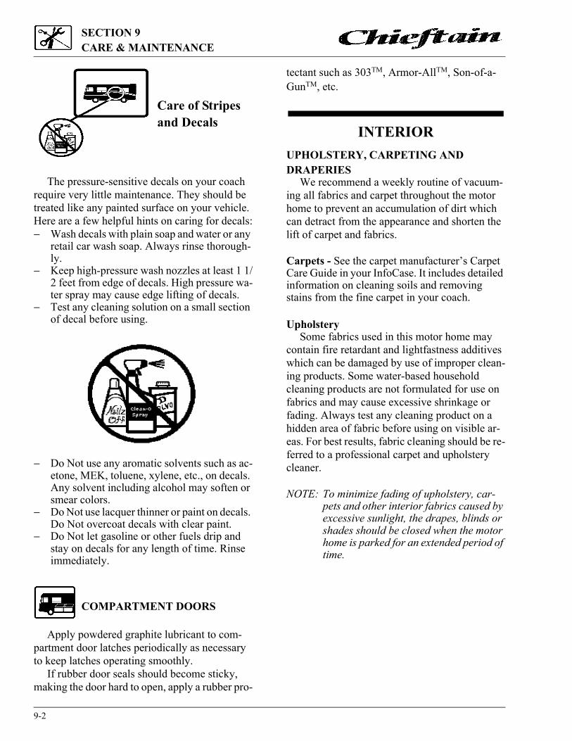
SECTION 9CARE & MAINTENANCE
9-2
Care of Stripes and Decals
The pressure-sensitive decals on your coach require very little maintenance. They should be treated like any painted surface on your vehicle. Here are a few helpful hints on caring for decals:� Wash decals with plain soap and water or any
retail car wash soap. Always rinse thorough-ly.
� Keep high-pressure wash nozzles at least 1 1/2 feet from edge of decals. High pressure wa-ter spray may cause edge lifting of decals.
� Test any cleaning solution on a small section of decal before using.
� Do Not use any aromatic solvents such as ac-etone, MEK, toluene, xylene, etc., on decals. Any solvent including alcohol may soften or smear colors.
� Do Not use lacquer thinner or paint on decals. Do Not overcoat decals with clear paint.
� Do Not let gasoline or other fuels drip and stay on decals for any length of time. Rinse immediately.
COMPARTMENT DOORS
Apply powdered graphite lubricant to com-partment door latches periodically as necessary to keep latches operating smoothly.
If rubber door seals should become sticky, making the door hard to open, apply a rubber pro-
tectant such as 303TM, Armor-AllTM, Son-of-a-GunTM, etc.
INTERIORUPHOLSTERY, CARPETING AND DRAPERIES
We recommend a weekly routine of vacuum-ing all fabrics and carpet throughout the motor home to prevent an accumulation of dirt which can detract from the appearance and shorten the lift of carpet and fabrics.
Carpets - See the carpet manufacturer’s Carpet Care Guide in your InfoCase. It includes detailed information on cleaning soils and removing stains from the fine carpet in your coach.
UpholsterySome fabrics used in this motor home may
contain fire retardant and lightfastness additives which can be damaged by use of improper clean-ing products. Some water-based household cleaning products are not formulated for use on fabrics and may cause excessive shrinkage or fading. Always test any cleaning product on a hidden area of fabric before using on visible ar-eas. For best results, fabric cleaning should be re-ferred to a professional carpet and upholstery cleaner.
NOTE: To minimize fading of upholstery, car-pets and other interior fabrics caused by excessive sunlight, the drapes, blinds or shades should be closed when the motor home is parked for an extended period of time.

9-3
SECTION 9CARE & MAINTENANCE
Spots and StainsSpots or stains should be treated as soon as
possible before they “set in” to avoid permanent damage. Always start from the outside of a spot or stain and work inward to avoid spreading it. Use a clean cloth or sponge and turn frequently to an unused area of the cloth or sponge as you clean.
Some stains or soils, such as lipstick, ink, grease or mustard, are extremely difficult or im-possible to remove completely and should re-ceive immediate attention. Consult a professional carpet and upholstery cleaner for assistance.
Vinyl FabricsVinyl should be cleaned with a soft, damp
cloth, and a mild detergent only. Do not use sol-vents. Solvents may damage the surface of the vi-nyl.
Draperies, Curtains and BedspreadsThese items may be woven from a variety of
fabrics. We recommend that these be profession-ally dry cleaned only. A five percent shrinkage may occur when you have these items dry cleaned.
CABINETRYWooden items may be cleaned with a soft
cloth and a good quality wood finish cleaning product such as GuardsmanTM or equivalent.
Vinyl simulated wood (Plus-Wood) panels may be cleaned with a mild, water based cleaner and a soft cloth. Do not use solvents on vinyl wood panels.
NOTE: Many cabinetry and furniture items throughout this motor home are con-structed either partially or completely of real hardwoods. Because of natural vari-ations in woodgrain density, slight dif-ferences in stain hue may exist between one item and another. This is the distinc-tive character and beauty of real wood.
Decorative Cabinet Mirrors and WindowsUse a good quality glass cleaner or mild soap
and water solution. It is best to use a spray bottle to apply a light mist rather than saturating the sur-face. WIPE DRY IMMEDIATELY. DO NOT ALLOW GLASS TO REMAIN WETTED FOR LONGER THAN A FEW SECONDS. Pro-longed moisture can cause the applique coating to lift from the surface of the glass.
Do not use sharp objects to scrape debris such as fly specks etc. Sharp objects can ship or lift the applique coating.
VINYL WALLBOARDDecorative vinyl covered wallboards may be
cleaned with a mild solution of water and isopro-pyl (rubbing) alcohol or a mild soap solution. Do not use solvents or abrasive cleaning products.
TABLES AND COUNTERTOPSWork surfaces are covered with a plastic lam-
inate that resists solvents, stains and abrasions. A coat of furniture wax applied to these surfaces on the counters and table will help preserve their beauty and make cleaning easier. Always clean the surface before applying wax.
STAINLESS STEEL SINKThe stainless steel sink can be cleaned with
soap or detergent. Rinse thoroughly with warm water and wipe dry to avoid streaks.
Use a mild abrasive for stubborn stains. Work in the direction of the polish lines. To keep the original finish, polish with a wax cleaner and rub with a dry soft cloth.
WARNINGWhen cleaning upholstery and fab-ric, do not use lacquer thinner, nail polish remover, laundry soaps, or bleach. Never use carbon tetrachlo-ride, gasoline, or naptha for any cleaning purpose. These materials may cause damage to the material being cleaned and most are highly flammable.

SECTION 9CARE & MAINTENANCE
9-4
BATHROOM
The tub and shower walls in the bathroom should be cleaned with a mild soap and water so-lution, or (to obtain maximum luster) use a good quality wax cleaner. Do not use an abrasive cleaner on the shower walls and tub. If the show-er has a glass door, it is extremely important that abrasives not be used. Use only a good quality glass cleaner or mild detergent and water solution with a soft cloth to clean glass surfaces.
The bathroom lavatory is also a molded plas-tic material and should be cleaned with a mild soap and water solution. Abrasive cleaners or harsh detergents should not be used.
For instructions on the care of your fresh water toilet, refer to the information in your Info-Case.
DOORS AND WINDOWSWindows may be periodically cleaned with a
good quality glass cleaner or mild soap solution using a soft cloth. Use care when removing ice or frost from the windows. Always use a plastic ice scraper, never one made of metal. Use care when removing ice from the mirrors to protect the re-flective surfaces.
Door locks and hinges should be lubricated periodically with powdered graphite to ensure trouble-free operation and to protect against freeze-up.
VEHICLE MAINTENANCE
(See also Safety Precautions, Section 1 of this manual).
CHASSIS SERVICE & MAINTENANCE
Consult the appropriate sections in your chas-sis operating guide for specific information re-garding operating safety, service recommendations and maintenance schedules for the chassis section of your motor home.
ENGINE ACCESS - Chevy or Ford Chassis
FRONT ACCESS PANEL (HOOD)Insert the tamper-resistant hood key into the
hood locks and turn them to the right (clockwise) to unlock the hood.
Swing the hood outward and down. Do not let hood drop.
To close the hood, lift and swing inward. Turn key locks to the left (counterclockwise) to lock hood closed.
With the hood open, the engine oil dipstick, oil fill, radiator fill, power steering reservoir and windshield washer reservoir are accessible. Some chassis also allow access to the engine air filter element.
ENGINE COVER (Chevy or Ford Chassis)Removal of the engine cover allows an autho-
rized service technician access to the engine for scheduled service and maintenance.
� Insert the supplied hex wrench into the hole in the lower rear edge of the engine cover.
WARNINGSalts, mustard and mayonnaise may causing pitting. If spilled, clean immediately.
Unlatch

9-5
SECTION 9CARE & MAINTENANCE
� Turn the hex wrench to the left (counter-clockwise) to unlatch.
� Lift the rear end of the cover upward and pull the cover from the opening.
� To return the cover, position the front end of the cover first, then lower the rear end. It is important to be sure the front edge is pushed completely forward to the radiator cover to ensure an air-tight seal.
� Press the rear end of the cover down and turn the hex wrench to the right (clockwise) until the latch pulls the cover downward and stops.
ENGINE ACCESS - Freightliner Diesel Chassis
REAR ENGINE GRILLEThe diesel engine is located behind the large
slotted grille in the rear of the vehicle. With the grille open, you can access the following service points:
� Engine Oil Dipstick (“Add” = 2 qts. low)� Engine Oil Fill Cap� Power Steering/Park Brake Fluid Reservoir� Radiator Cap� Engine Coolant Overflow Bottle� Transmission Dipstick/Fill Tube� Air Filter Restriction Indicator
Unlock the grille and swing it open upward. A catch is located on the backwall to hold the grille open.
ENGINE TOP COVERThe engine top cover is located beneath the
rear bed. This cover is only removed for replace-ment of engine parts or if a complete view of the engine is needed for inspection. To do this, re-move the mattress from the bed and lift the hinged bed board upward. Support the bed board with a prop rod while accessing engine.
Routine engine inspection can be performed (with protective clothing) under the left rear side of the vehicle, between the luggage compartment and engine exhaust muffler.
FUEL/WATER SEPARATORDiesel fuel often contains small quantities of
water which can damage the engine if not filtered out. The fuel/water separator traps this water and prevents it from reaching the engine. The harmful water deposits must be drained from the separa-tor canister during normal periodic service and maintenance to keep the fuel filtration system working effectively.
The fuel/water separator is located beneath the sidewall behind the rear wheels on the right (pas-senger) side of the coach.
Place an appropriate container beneath the outlet and screw the water release valve open several turns. Drain any water deposits from the canister until clean diesel fuel flows from the valve. Close valve by hand. Do not over tighten.
Dispose of the drained liquid in an environ-mentally responsible manner, such as taking to a waste oil disposal.
ENGINE COOLING SYSTEM
Refer to your chassis operating guide for in-formation and precautions on filling, servicing and checking the fluid level.
Fuel/Water Drain Valve

SECTION 9CARE & MAINTENANCE
9-6
TIRES
Low air pressure results in tire overloading and abnormal wear and also affects handling and fuel economy. Obtain proper inflation pressures from your chassis operating guide or tire manu-facturer.
See the Vehicle Certification Label affixed to the lower inside of the driver’s door for tire information.
SUSPENSION ALIGNMENT AND TIRE BALANCE
The front suspension and steering system of this vehicle was factory aligned using highly ac-curate equipment prior to delivery to the dealer-ship. However, we recommend that alignment be checked and adjusted, if necessary, after you have fully loaded the motor home according to your personal needs. Thereafter, the alignment should be periodically inspected to help prevent uneven tire wear.
Any excessive or abnormal tire wear may in-dicate worn or misaligned suspension or steering, unbalanced tire or other tire/suspension problem.
Alignment can be affected by worn steering/suspension parts or by incidents which happen
during driving, such as hitting a curb, pothole or railroad track, etc. Improper alignment can cause tires to roll at an angle and wear unevenly. It may also cause the vehicle to “pull” to the right or left. Have your dealer inspect your vehicle’s suspen-sion and steering components periodically for misalignment or wear.
Out-of-balance tires will not roll smoothly and can lead to annoying vibrations and uneven tread wear such as cupping and flat spots. Tires may need to be balanced if uneven wear is detected or if ride comfort decreases noticeably.
See your chassis operating guide for further information.
WINDSHIELD WASHERS AND WIPERS
See your chassis operating guide for recom-mendations and precautions regarding washers and wipers.
LIGHTS
All exterior lights should be checked for prop-er operation each time the vehicle is prepared for a trip. Any bulbs which fail to light should be checked and replaced, when necessary, with a new bulb of the same size. A failure of more than one light, such as both taillights not operating, may indicate a burned out fuse. Check fuse and replace with one of the same rating when neces-sary. If a fuse is not the cause of the problem, the wiring system should be checked immediately by an authorized service center.
The headlight circuit is protected by an auto reset circuit breaker built into the headlight switch. An overload on the breaker will cause the lights to flicker on and off. Headlight wiring should be checked immediately anytime this con-dition is apparent. Refer to your chassis operating guide for further information.
CAUTIONWhen refilling the coolant system of a vehicle equipped with a rear auxil-iary automotive heater and motoraid water heater, be sure to allow for additional coolant capacity of the heater and its supply and return hoses.
WARNINGMake sure all replacement tires are of the same size and ply rating as those installed as original equipment.

9-7
SECTION 9CARE & MAINTENANCE
AUTOMOTIVE 12-VOLT FUSES AND CIRCUIT BREAKERS
The automotive fuses and breaker are con-veninently located on the automotive fuse block below the left side of the dash (ahead of driver’s left foot).
The circuit breakers will pop outward if they are tripped. Simply push in to reset.
Always replace plug-in type fuses with those of the same amperage size.
15 15
GOOD FUSE BAD FUSE
PLUG-IN FUSES

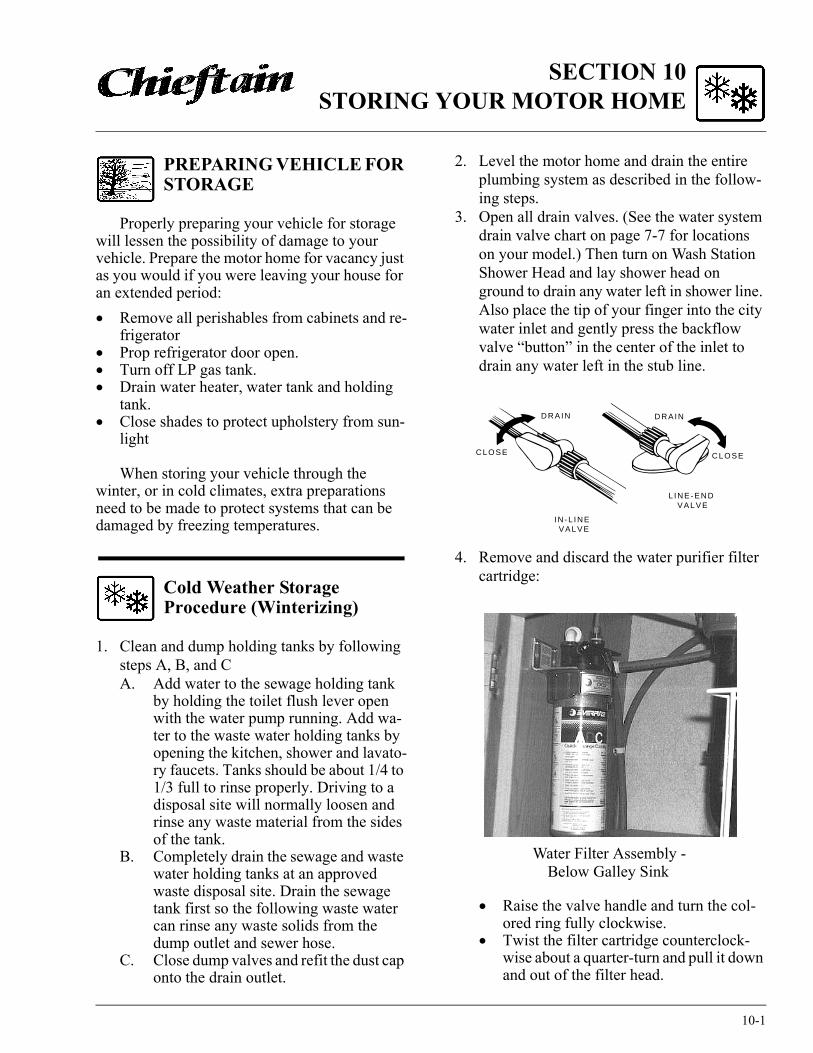
SECTION 10STORING YOUR MOTOR HOME
10-1
PREPARING VEHICLE FOR STORAGE
Properly preparing your vehicle for storage will lessen the possibility of damage to your vehicle. Prepare the motor home for vacancy just as you would if you were leaving your house for an extended period:� Remove all perishables from cabinets and re-
frigerator� Prop refrigerator door open.� Turn off LP gas tank.� Drain water heater, water tank and holding
tank.� Close shades to protect upholstery from sun-
light
When storing your vehicle through the winter, or in cold climates, extra preparations need to be made to protect systems that can be damaged by freezing temperatures.
Cold Weather Storage Procedure (Winterizing)
1. Clean and dump holding tanks by following steps A, B, and CA. Add water to the sewage holding tank
by holding the toilet flush lever open with the water pump running. Add wa-ter to the waste water holding tanks by opening the kitchen, shower and lavato-ry faucets. Tanks should be about 1/4 to 1/3 full to rinse properly. Driving to a disposal site will normally loosen and rinse any waste material from the sides of the tank.
B. Completely drain the sewage and waste water holding tanks at an approved waste disposal site. Drain the sewage tank first so the following waste water can rinse any waste solids from the dump outlet and sewer hose.
C. Close dump valves and refit the dust cap onto the drain outlet.
2. Level the motor home and drain the entire plumbing system as described in the follow-ing steps.
3. Open all drain valves. (See the water system drain valve chart on page 7-7 for locations on your model.) Then turn on Wash Station Shower Head and lay shower head on ground to drain any water left in shower line. Also place the tip of your finger into the city water inlet and gently press the backflow valve “button” in the center of the inlet to drain any water left in the stub line.
4. Remove and discard the water purifier filter cartridge:
� Raise the valve handle and turn the col-ored ring fully clockwise.
� Twist the filter cartridge counterclock-wise about a quarter-turn and pull it down and out of the filter head.
DRAIN DRAIN
CLOSE CLOSE
IN-L INE VALVE
L INE-END VALVE
Water Filter Assembly - Below Galley Sink

SECTION 10STORING YOUR MOTOR HOME
10-2
� Place a container beneath the filter head and lower the valve handle to drain any water remaining in the filter lines.
5. Install the antifreeze diverter plug:
� Raise the valve handle and turn the col-ored ring fully clockwise.
� Hold the diverter by the support bar as shown and guide it up into the filter head with bar end approximately centered in colored ring cutout.
� Push the diverter up into the head as far as possible and turn it clockwise approxi-mately a quarter-turn.
� Then turn colored ring fully counter-clockwise. The diverter should be locked in position between the head and colored ring.
� Lower valve handle to lock colored ring in place.
6. Turn the Water Pump switch ON to allow it to operate until you are done draining all fau-cets and toilet.
7. Open all faucets and shower head valves, including exterior shower.
8. Operate the toilet flush lever and hold until water stops flowing in the toilet. Then turn water pump switch OFF.
9. Turn off the water heater power switch before draining the water heater tank to avoid damage to the heating element.Drain the water heater by removing the plug from the base of the water heater tank, acces-
sible from the outside of the coach. (Requires socket and ratchet.) Also open the Pressure-Temperature relief valve at the top right portion of the tank to prevent air lock-ing in the tank while draining.
10. After water has stopped draining at all fau-cets and drain valves, connect a “blow-out” plug to the city water connection on the coach. Then use a hand pump or air com-pressor regulated to 30 psi or less to force air through the system. (A “blow-out” plug can be purchased at any Winnebago or Itasca dealer. P/N 701705-01-000.)
CAUTIONLimit air pressure to 30 psi to avoid damage to pump or water lines.
Water Heater Drain Plug(Remove with Wrench)
P-T Relief Valve
City WaterConnection

10-3
SECTION 10STORING YOUR MOTOR HOME
NOTE: DO NOT burst air into the system. This can damage the water pump. It is better to let air in slowly.
11. Let air flow for five minutes until water is completely drained out of faucets and drain valves. Then close faucets one at a time.
12. Operate and hold toilet flush lever until water is completely drained from toilet.
13. Now turn air pressure off and disconnect water purge adapters. Recap the city water connection to avoid contamination by dirt or insects.
14. Close all drain valves and faucets to avoid contamination by dirt or insects. Reinstall water heater drain plug and close P-T relief valve.
15. Pour about one cup of non-toxic RV anti-freeze into the kitchen sink drain, bathroom sink drain and shower drain. This prevents any holding tank odors from entering the coach during storage.
It is not necessary to add antifreeze to the toi-let since the flush valve will be closed.
Do not add automotive antifreeze or caustic chemicals such as bleach or laundry deter-gents into the toilet bowl or holding tanks. Although these products may have a deodor-izing effect, they may damage plastic and rubber parts in the system.
NOTE: As an alternative to totally draining the plumbing system, you may winter-ize tanks and lines by pumping non-toxic RV antifreeze through the sys-tem. This product is available from your dealer and from most RV supply stores. Follow directions on the con-tainer to determine the correct amount to use for your coach.
See “RV Antifreeze Water Line Win-terization Systems” on page 10-4 for instructions on filling with RV anti-freeze.
If your coach is equipped with the op-tional water heater by-pass valve, you can fill the hot water lines with anti-freeze solution without filling the wa-ter heater tank. See page 8-8 for information on the by-pass valve.
16. Place a bucket beneath the sewage drain valve outlet and re-drain the sewage and waste holding tanks of any clean water that entered during “blow-out” procedure.
Close dump valves to prevent valve shafts from rusting and to prevent entry by rodents and insects. Refit the dust cap onto the drain outlet.
Your drainage and fresh water systems are now totally winterized.
17. Have the vehicle chassis completely serviced and lubricated. Be sure radiator antifreeze protection level is sufficient for the lowest anticipated temperatures.
18. Wash and wax the coach.
WARNINGNEVER use automotive antifreeze/coolant in your RV water system. Auto antifreeze contains ethylene glycol which, if ingested, can cause blindness and can be fatal.
1
CAUTIONLeave by-pass valve handle in NOR-MAL FLOW position if draining water and blowing out water lines. Place in BYPASS position ONLY when using antifreeze solution in water lines.
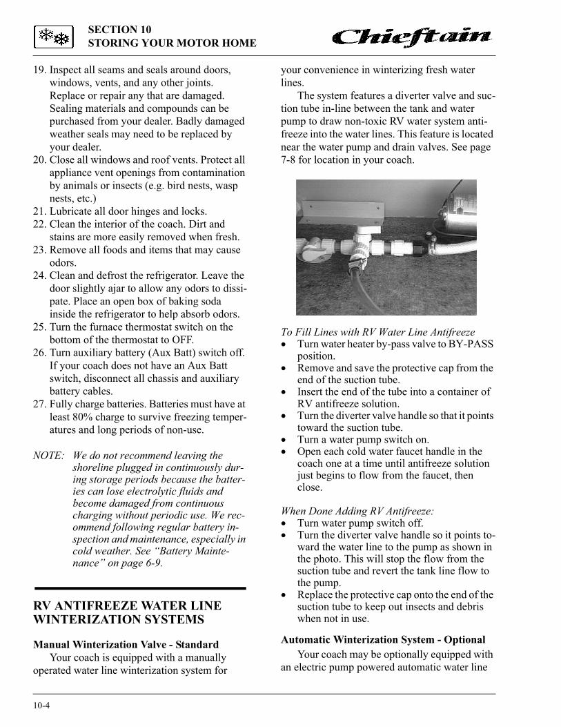
SECTION 10STORING YOUR MOTOR HOME
10-4
19. Inspect all seams and seals around doors, windows, vents, and any other joints. Replace or repair any that are damaged. Sealing materials and compounds can be purchased from your dealer. Badly damaged weather seals may need to be replaced by your dealer.
20. Close all windows and roof vents. Protect all appliance vent openings from contamination by animals or insects (e.g. bird nests, wasp nests, etc.)
21. Lubricate all door hinges and locks.22. Clean the interior of the coach. Dirt and
stains are more easily removed when fresh.23. Remove all foods and items that may cause
odors.24. Clean and defrost the refrigerator. Leave the
door slightly ajar to allow any odors to dissi-pate. Place an open box of baking soda inside the refrigerator to help absorb odors.
25. Turn the furnace thermostat switch on the bottom of the thermostat to OFF.
26. Turn auxiliary battery (Aux Batt) switch off. If your coach does not have an Aux Batt switch, disconnect all chassis and auxiliary battery cables.
27. Fully charge batteries. Batteries must have at least 80% charge to survive freezing temper-atures and long periods of non-use.
NOTE: We do not recommend leaving the shoreline plugged in continuously dur-ing storage periods because the batter-ies can lose electrolytic fluids and become damaged from continuous charging without periodic use. We rec-ommend following regular battery in-spection and maintenance, especially in cold weather. See “Battery Mainte-nance” on page 6-9.
RV ANTIFREEZE WATER LINE WINTERIZATION SYSTEMS Manual Winterization Valve - Standard
Your coach is equipped with a manually operated water line winterization system for
your convenience in winterizing fresh water lines.
The system features a diverter valve and suc-tion tube in-line between the tank and water pump to draw non-toxic RV water system anti-freeze into the water lines. This feature is located near the water pump and drain valves. See page 7-8 for location in your coach.
To Fill Lines with RV Water Line Antifreeze� Turn water heater by-pass valve to BY-PASS
position.� Remove and save the protective cap from the
end of the suction tube.� Insert the end of the tube into a container of
RV antifreeze solution.� Turn the diverter valve handle so that it points
toward the suction tube.� Turn a water pump switch on.� Open each cold water faucet handle in the
coach one at a time until antifreeze solution just begins to flow from the faucet, then close.
When Done Adding RV Antifreeze:� Turn water pump switch off.� Turn the diverter valve handle so it points to-
ward the water line to the pump as shown in the photo. This will stop the flow from the suction tube and revert the tank line flow to the pump.
� Replace the protective cap onto the end of the suction tube to keep out insects and debris when not in use.
Automatic Winterization System - OptionalYour coach may be optionally equipped with
an electric pump powered automatic water line

10-5
SECTION 10STORING YOUR MOTOR HOME
winterization system for your convenience in winterizing fresh water lines.
The reservoir tank for the RV water system antifreeze is located in the rear cargo compart-ment on the passenger side of the coach. Remove the large black plug and use a funnel to fill the tank. Capacity is approximately 2 gal-lons. The tank may require refilling before the system is completely filled.
The winterization system switch panel is located near the floor below the refrigerator.
� Press the bypass switch to avoid filling the 6 gallon water heater tank with antifreeze after draining the water heater at the service panel on the outside of the coach. If you should wish to fill the water heater tank with anti-freeze solution, leave this switch off.
� Press the WINTERIZE switch to turn the winterizing pump system on to fill the lines with RV antifreeze solution.
REMOVAL FROM STORAGE
1. Completely air out the motor home.2. Have the entire LP gas system checked for
leaks.3. Check window operation.4. Check cabinet and door hinges. Lubricate
with penetrating oil, if necessary.
5. Close all faucets and drain valves that are open. If necessary, reconnect toilet water line and close flush valve.
6. Add a few gallons of water to the fresh water tank and check for leaks especially at junc-tions. Also make sure all hangers and sup-ports are securely in place. Sanitize the water system as outlined under “Disinfecting the Fresh Water System” in Section 7.
7. Check operation of all faucets to be sure fau-cet washers have not hardened during stor-age.
8. Check sealing valve in the toilet for proper operation and lubricate with silicone spray.
9. Add water to the holding tank using the toilet flush pedal. Check to be sure dump valve seals tightly.
10. Check around all appliances for obstructions and ensure that all vent openings are clear.
11. Start refrigerator and check for proper cool-ing.
12. Clean paneling and counter surfaces and apply a thin coat of wax.
13. Replace batteries if necessary and check out electrical system to make sure all lights and electrical components operate.
14. Check tires for proper cold inflation pres-sure.
15. After washing accumulated winter grime from the vehicle, it is important to carefully inspect the seams and sealants for separation or cracks that may have appeared around the window frames, vents and any other joints. Re-sealing is quite simple and the material is quickly and easily applied. Appropriate com-pounds are available from your dealer. Also inspect weather seals around doors, etc., and if necessary, have a dealer replace immedi-ately.
Automatic Winterization Panel


INDEX
AAccumulator Tank ......................................... 7-2Air Conditioner, Automotive ....................... 2-15 Air Conditioner, Ducted Roof ..................... 8-10Alarm, LP Gas ............................................. 1-3Alignment, Front Axle Tire ........................... 4-1Alignment, Suspension and Tire Balance...... 9-6Amplifier, Antenna Signal .......................... 8-11Antenna, CB SWR Adjustment ................... 2-17Antenna, TV ................................................ 8-10Antenna Signal Amplifier ............................ 8-11Antifreeze, RV Winterization Systems........ 10-4Automatic Power Transfer Switch (Generator)................................................. 6-5Automatic Winterizing System.................... 10-4Automotive (Starting) Batteries..................... 6-7Auto 12V Fuses & Circuit Breakers .............................................6-7, 9-7Auxiliary Battery Switch ............................. 2-17Aux Start Switch .......................................... 2-16Auxiliary (Coach) Batteries ........................... 6-7Auxiliary 110-Volt Generator........................ 6-5
BBathroom, Care of.......................................... 9-4Batteries, Automotive (Starting) ................... 6-7Batteries, Auxiliary (Coach) ......................... 6-7Battery Charger, Connecting ......................... 3-5Battery Condition Meter ............................... 8-7Battery Information........................................ 6-7Battery Maintenance ...................................... 6-9Battery Switch, Aux..................................... 2-14Beds, Converting for use ............................. 8-13Before Driving your Vehicle ......................... 2-1Before Entering your Vehicle ........................ 2-1Black Water Holding Tank Flushing ............. 7-6Block Heater, Engine (Freightliner) .............. 2-4Brake, Parking .............................................. 2-4By-Pass Valve, Water Heater ........................ 8-8
CCabinets ......................................................... 9-3Cable TV Hook-Ups .................................... 8-12Campsite Selection ........................................ 4-6Capacities**
Fuel Tank* .................................................. 2-2 Fresh Water Tank *.................................... 7-1 Holding Tanks *......................................... 7-5
Water Heater *............................................. 8-7Carbon Monoxide Alarm .............................. 1-5Carbon Monoxide Warning .......................... 1-5Carpets, Care of ............................................. 9-2Central Vacuum Cleaner - Optional ............ 8-15CB Antenna, SWR Adjustment ................... 2-17CB Radio Wiring ......................................... 2-17Charger Panel, Solar (Optional).................... 6-8Charging Section............................................ 6-4Chassis Operating Guide .............................. 0-1Chassis Service and Maintenance.................. 9-4Checklist, Pre-Travel .................................. 4-3Child Restraints............................................ 2-10Circuit Breakers, 12-Volt ....................... 6-7, 9-6Circuit Breakers, 110-Volt ............................ 6-4City Water Hook-Up...................................... 7-3Coach Leveling System ............................... 2-18Cold Weather Storage (Winterizing) ........... 10-1Comfort Controls ......................................... 2-14Compact Disc (CD) Changer....................... 2-16Compartment Doors, Luggage....................... 2-7Condensation, Humidity and ........................ 4-7Connecting a Battery Charger........................ 3-4Connecting the Shoreline............................... 6-2Control Center, Video.................................. 8-12Converter, Electrical Power........................... 6-3Converter Overload Protector ........................ 6-4Cooling System, Engine ................................ 9-5Couch/Bed Conversion ................................ 8-13Crank-Out Windows .................................... 8-15Cruise Control ............................................. 2-14
DDay/Night Pleated Shades ........................... 8-15DC-AC Electrical Inverter ........................... 8-13Decals and Stripes ......................................... 9-2Defects, Reporting Safety ............................. 0-2Defroster ...................................................... 2-15Deluxe Sound System.................................. 2-16Diesel Engine Block Heater .......................... 2-4Diesel Fuel/Water Separator .......................... 9-5Dinette/Bed Conversion............................... 8-14Disinfection of Fresh Water Tank ................ 7-3Door Handles and Locks................................ 2-6
* Capacity chart is also conveniently located on the back of “To The Owner” page inside front cover of this manual.

INDEX
Doors and Windows, Care of......................... 9-3Doors, Luggage Compartment....................... 2-7Door Locks, Entrance .................................... 2-6Drain Valves, Water ..............................7-7, 7-8Drainage System ............................................ 7-5Draperies, Care of .......................................... 9-2Drinking and Driving..................................... 0-2Driver Seat ..................................................... 2-7Driving Safety Precautions ............................ 1-1Dual Rear Wheels .......................................... 3-3Dumping Holding Tanks .............................. 7-5
EEffects of Prolonged Occupancy ................... 4-7Electrical Inverter, DC-AC ......................... 8-13Electrical Outlets, 110-volt ............................ 6-5Electrical Safety Precautions ......................... 1-4Electrical System, 110-volt AC ..................... 6-1Electrical System, 12-volt DC ....................... 6-7Emergency Crank-In, Slide-Out Room........ 2-20Emergency Equipment Checklist................... 4-3Emergency Exits ............................................ 1-5Energy Management System, PowerLine...... 6-2Engine Access................................................ 9-4Engine Block Heater, (Freightliner) .............. 2-3Engine Cooling System ................................. 9-6Engine Exhaust Brake (Freightliner) ............. 2-5Engine Overheat............................................. 3-5Engine Top Cover .......................................... 9-4Entertainment Center, Exterior ................... 8-13Entrance Door Lock and Handle.................... 2-6Entrance Steps, Electric Powered .................. 2-6Equipment, Options and ............................... 0-2Equipping for Travel...................................... 4-3Exhaust Brake, Engine (Freightliner) ............ 2-5Exits, Emergency .......................................... 1-6Extending Slide-Out Room.......................... 2-20Exterior Body Care ........................................ 9-1Exterior Entertainment Center ..................... 8-13Exterior Features............................................ 0-5Exterior Shower ............................................. 7-5External (City Water) Connector ................... 7-3External Power Cord (Shoreline)................... 6-1
FFilling the Fuel Tank...................................... 2-2Filter, Diesel Fuel/Water................................ 9-5Fire Extinguisher ........................................... 1-7Flushing Black Water Holding Tank ............. 7-6Formaldehyde Warning ................................ 1-5Fresh Water Tank........................................... 7-1 Disinfection of ............................................. 7-3
Drain ............................................................ 7-6 Filling .......................................................... 7-1Fresh Water Toilet ....................................... 8-14Front Axle Tire Alignment ............................ 4-1Fuel Pump Shutoff Switch (Ford).................. 2-3Fuel Selection ................................................ 2-2Fuel Selection, Diesel .................................... 2-3Fuel Tank Capacity ........................................ 2-2Fuel Tank, Filling ......................................... 2-2Fuel Tank, Filling Diesel ............................... 2-3Fuel/Water Separator (Diesel) ....................... 9-5Furnace , LP Gas ........................................... 8-9
GGas Alarm, LP ............................................. 1-3Gas Leaks, LP .............................................. 5-5General Warnings .......................................... 1-1Generator, Auxiliary 110-Volt ...............6-5, 6-7Generator Hourmeter ..................................... 6-6Ground Fault Circuit Interrupter.................... 6-4
HHazard Warning Flashers............................... 3-1Heater, Diesel Engine (Freightliner) ............. 2-4Heater, Automotive...................................... 2-12Holding Tank Level Indicators ..................... 8-7Hourmeter, Generator ................................... 6-6Humidity and Condensation .......................... 4-6
IInstrument Panel .......................................... 2-13Interior Care............................................9-2, 9-4Inverter, DC-AC Electrical ......................... 8-13
JJet Air Ride Park & Level System............... 2-18Jump Starting ................................................. 3-4
KKeys ............................................................... 2-6
LLeveling, Coach ....................................2-18, 4-6Leveling System, Coach ............................. 2-18Lights ............................................................. 9-6Loading, Roof ............................................... 4-2Loading the Vehicle ...................................... 4-1Locks, Entrance Door .................................... 2-6Lounge Chairs................................................ 2-8LP Gas Alarm ................................................ 1-3LP Gas Furnace ............................................. 8-9LP Gas Leaks ..........................................1-2, 5-4

INDEX
LP Gas Level ................................................. 8-7LP Gas Pressure Regulator ........................... 5-3LP Gas Safety ................................................ 5-1LP Gas Selection............................................ 5-2LP Gas Tank, Air in the ............................... 5-3LP Gas Tank, Refilling ................................ 5-3LP Gas Tank System...................................... 5-2LP Gas, Travel with ..................................... 5-3LP Gas, Winter Use of .................................. 5-5Luggage Compartment Doors........................ 2-7
MMaximum Occupancy.................................... 4-2Microwave Oven............................................ 8-6Mirrors, Power Electric ............................... 2-11Monitor, Rearview TV................................. 2-11Monitor Panel ............................................... 8-6Motor Aid Water Heater ................................ 8-9Mountain Driving .......................................... 4-5
NNighttime Driving.......................................... 4-5
OOccupancy, Effects of Prolonged ................. 4-7Occupancy, Maximum................................... 4-1Operating the Oven........................................ 8-6Operators Manual .......................................... 0-1Options and Equipment ................................. 0-2Outlets , 110-Volt ......................................... 6-5Oven Pilot ...................................................... 8-6Overload Protector, Converter ...................... 6-4
PPark & Level System, Jet Air ..................... 2-18Parking Brake ................................................ 2-4Phone Jack Locations................................... 8-12Pilot, Lighting Oven ..................................... 8-6Pleated Shades, Day/Night .......................... 8-15Power Converter System ............................... 6-3Power Electric Mirrors................................. 2-11PowerLine Energy Management System....... 6-2Power Roof Vent ......................................... 8-15Power Seat, Driver Six-Way.......................... 2-8Power Step, Entrance .................................... 2-6Pre-Travel Checklist ..................................... 4-3Preparing Vehicle for Storage ..................... 10-1Pressure Regulator, LP Gas ........................... 5-4Prolonged Occupancy, Effects of ................. 4-6Pump Switch, Water ...................................... 7-2
RRadio/Cassette Player, Dash ........................ 2-16Radio Switch................................................ 2-16Radio Wiring, CB ....................................... 2-17Range and Oven ............................................ 8-5Range Hood .................................................. 8-6Rear Engine Access, Diesel ........................... 9-5Rearview TV Monitor.................................. 2-11Recovery Towing........................................... 3-3Refrigerators ..........................................8-1 - 8-5Regulator, LP Gas ........................................ 5-4Relief Valve, Water Heater............................ 8-8Removal from Storage ................................ 10-5Reporting Safety Defects ............................... 0-2Restraints, Child........................................... 2-10Retracting Slide-Out Room ......................... 2-20Roof Loading ................................................. 4-2Roof Maintenance.......................................... 9-1Roof Vent, Power ........................................ 8-15RV Antifreeze Winterization Systems......... 10-4
SSafe Use of LP Gas System ........................... 5-1Safety Defects, Reporting ............................. 0-2Safety Precautions.......................... 1-1 - 1-6, 3-2Satellite TV System - Optional .................... 8-12Seat, Driver ................................................... 2-7Seat Belts and Child Restraints.............2-8, 2-10Seats ............................................................... 2-7Selecting Fuel Types, LP ............................... 5-2Service Assistance ......................................... 0-2Severe Weather Information ......................... 4-4Sewer Hook-Ups, Using On-Site .................. 7-6Shades, Day/Night Pleated .......................... 8-15Shoreline, Connecting the ............................. 6-2Shower, Exterior ........................................... 7-5Shower Hose Vacuum Breaker...................... 7-4Shutoff Switch, Fuel Pump (Ford)................. 2-3Signal Amplifier, TV Antenna..................... 8-11Sink, Stainless Steel ..................................... 9-3Sleeping Facilities........................................ 8-13Slider Windows............................................ 8-15Slideout Living Room.........................2-20–2-23
Emergency Crank-In ................................ 2-21Extending ................................................. 2-20Retracting ................................................. 2-21Travel Latches .......................................... 2-20
Solar Charger Panel (Optional)...................... 6-8Solar Panel Wiring......................................... 6-8Sound Systems............................................. 2-16Spare Tire....................................................... 3-1Speed Control (Cruise) ................................ 2-14

INDEX
Spots and Stains ............................................. 9-3Start Switch, Aux ........................................ 2-16Starting and Stopping the Engine .................. 2-3Step, Electric Power Entrance ....................... 2-6Storage, Preparing Vehicle for .................... 10-1Storage, Removal from .............................. 10-5Stripes and Decals.......................................... 9-1Suspension Alignment and Tire Balance....... 9-5Switch, Radio .............................................. 2-16SWR Adjustment, CB Antenna ................... 2-17
TTable and Countertop Surfaces...................... 9-3Tank , Fresh Water Filling ............................ 7-1Tank Capacities, Water and Holding ............. 7-7Telephone Hook-Ups ................................... 8-12Thermostat, Electronic - Furnace................... 8-9Tire Alignment, Front Axle ........................... 4-1Tire, Spare ..................................................... 3-1Tire Balance, Suspension Alignment and ..... 9-5Tire Changing ................................................ 3-2 Tires ............................................................... 9-5Toilet, Fresh Water ..................................... 8-14Towing, Recovery ......................................... 3-3Trailer Towing ............................................... 4-2Trailer Wiring Connector............................. 6-10Travel Latches, Slide-Out Room ................. 2-17Travel Tips ..................................................... 4-3Travel with LP Gas ....................................... 5-3TV Antenna.................................................. 8-10TV & Cable Hook-Ups, .............................. 8-12TV Signal Amplifier .................................... 8-11TV Monitor, Rearview (Backup Monitor)... 2-11
UUnderbody Care ............................................. 9-1Upholstery...................................................... 9-2 Using On-Site Sewer Hook-Ups.................... 7-6
VVehicle Certification Label (VIN) ................. 0-4Vehicle Maintenance ..................................... 9-4Vents, Power Roof ....................................... 8-15Video Control Center................................... 8-12Vinyl Fabrics ................................................. 9-3Vinyl Wallboard ............................................ 9-3Voltage Inverter, DC-AC Electrical ........... 8-13WWarnings: Carbon Monoxide ....................................... 1-5 Driving ......................................................... 1-1
Formaldehyde ............................................ 1-5 Fuel & LP Gas ............................................. 1-2 LP Gas Leaks ............................................... 1-2 LP Gas Alarm .............................................. 1-3 Electrical ..................................................... 1-4 Loading ........................................................ 1-4 Maintenance................................................. 1-4Warranty ........................................................ 0-2Water and Holding Tank Levels ................... 8-7Water Drain Valves ...............................7-7, 7-8Water Heater, Motor Aid .............................. 8-9Water Heater .................................................. 8-7Water Heater By-Pass Valve ......................... 8-8Water Heater Capacity................................... 8-8Water Line Drain Valves ........................7-7, 7-8Water Pump ................................................... 7-2Water Pump Switch ...............................7-2, 8-9Water Purifier System.................................... 7-4Water Tank, Disinfection of ......................... 7-3Water Tank Filling ........................................ 7-1Weighing Your Loaded Vehicle .................... 4-1Wheels, Rear Dual ......................................... 3-3Wheel Nuts .................................................... 3-3Windows, Cleaning ....................................... 9-4Windows, Crank-Out .................................. 8-15Window Shades, Pleated.............................. 8-15Windows, Slider .......................................... 8-15Windows, Doors and ..................................... 9-4Windows, Emergency Exit ........................... 1-6Windshield Washers and Wipers ................... 9-6Windshield Wiper/Washer Switch............... 2-14Winter Use of LP Gas ................................... 5-5Winterization Systems, RV Antifreeze........ 10-4Winterizing ........................................10-1 - 10-5Wiring, CB Radio ....................................... 2-17Wiring, Trailer Connector............................ 6-10

IMPORTANTSERIAL NUMBERS
Motor Home (Coach): Year _________ Model ___________________ Serial _____________ Chassis: Make ___________________ Serial (VIN) ______________
Air Conditioner:Brand Model ___________ Serial___________________Furnace: Brand ___________ Model ____________ Serial____________Water Heater: Brand ___________ Model ____________ Serial____________Power Converter: Brand ___________ Model ____________ Serial____________110-Volt Generator: Brand ___________ Model ____________ Serial ___________Range Brand ___________ Model ____________ Serial____________Microwave Oven: Brand ___________ Model ____________ Serial____________Refrigerator Brand ___________ Model ____________ Serial____________Television: Brand ___________ Model ____________ Serial____________Video Cassette Player: Brand ___________ Model ____________ Serial____________
EMERGENCY INFORMATION
DealerName _______________________________________________________________________Address__________________________________________________________________________________________________________________________________________________
Phone _______________________________________________________________________
INSURANCE POLICYCompany ____________________________________________________________________Policy Number ________________________________________________________________Phone _______________________________________________________________________

MAINTENANCE RECORD
DateOdometerMileage Description of Service Cost

FUEL & OIL RECORD
DateOdometerMileage
FuelGal.
OilQts. MPG Cost Date
OdometerMileage
FuelGals.
OilQts. MPG Cost

FUEL & OIL RECORD
DateOdometerMileage
FuelGal.
OilQts. MPG Cost Date
OdometerMileage
FuelGals.
OilQts. MPG Cost


![Warragul · 2020. 9. 25. · 4-0-1-0 3-0-1-0 $235 Winning Boxes 2 BLACKJACK LEE ... 1-0-0-0 $0 Winning Boxes 7 ALARM RESPONSE [M] Far from disgraced on debut, must keep safe Owner(s):](https://img.pdfslide.us/doc/110x75/607201678a3f731bbf429e1a/warragul-2020-9-25-4-0-1-0-3-0-1-0-235-winning-boxes-2-blackjack-lee-1-0-0-0.jpg)