Embed Size (px)
Citation preview
A COMPLIANCE MANAGEMENT FRAMEWORKFOR BUSINESS PROCESS MODELS
AHMED MAHMOUD HANY ALY AWAD
BUSINESS PROCESS TECHNOLOGY GROUPHASSO PLATTNER INSTITUTE, UNIVERSITY OF POTSDAM
POTSDAM, GERMANY
DISSERTATIONZUR ERLANGUNG DES AKADEMISCHEN GRADES
"DOCTOR RERUM NATURALIUM"(DR. RER. NAT.)
— DOCTORAL THESIS —
MAY, 2010

Published online at the Institutional Repository of the University of Potsdam: URL http://opus.kobv.de/ubp/volltexte/2010/4922/ URN urn:nbn:de:kobv:517-opus-49222 http://nbn-resolving.org/urn:nbn:de:kobv:517-opus-49222

To Radwa my wife and Nour my daughter the innocent soul

Zusammenfassung
Firmen entwickeln Prozessmodelle um ihre Geschäftstätigkeit explizit zu beschreiben.Geschäftsprozesse müssen verschiedene Arten von Compliance-Anforderungen einhalten.Solche Compliance-Anforderungen entstammen einer Vielzahl von Quellen, z.B. Verord-nung wie dem Sarbanes Oxley Act von 2002, interne Richtlinien und Best Practices. DieNichteinhaltung von Compliance-Anforderungen kann zu gesetztlichen Strafen oder demVerlust von Wettbewerbsvorteilen und somit dem Verlust von Marktanteilen führen.
Im Gegensatz zu dem klassischen, domänen-unabhängigen Begriff der Korrektheitvon Geschäftsprozessen, sind Compliance-Anforderungen domain-spezifisch und än-dern sich im Laufe der Zeit. Neue Anforderungen resultieren aus neuen Gesetzen undder Einführung neuer Unternehmensrichtlinien. Aufgrund der Vielzahl der Quellen fürCompliance-Anforderungen, können sie unterschiedliche Ziele verfolgen und somit wider-sprüchliche Aussagen treffen. Schliesslich betreffen Compliance-Anforderungen ver-schiedene Aspekte von Geschäftsprozessen, wie Kontrollfluss- und Datenabhängigkeiten.Auf Grund dessen können Compliance-Prüfungen nicht direkt Hard-coded werden.Vielmehr ist ein Prozess der wiederholten Modellierung von Compliance-Regeln undihrer anschliessenden automatischen Prüfung gegen die Geschäftsprozesse nötig.
Diese Dissertation stellt einen formalen Ansatz zur Überprüfung der Einhaltungvon Compliance-Regeln während der Spezifikation von Geschäftsprozessen vor. Mitvisuellen Mustern ist es möglich, Compliance-Regeln hinsichtlich Kontrollfluss- undDatenabhängigkeiten sowie bedingte Regeln zu spezifizieren. Jedes Muster wird in eineFormel der temporalen Logik abgebildet. Die Dissertation behandelt das Problem derKonsistenzprüfung zwischen verschiedenen Compliance-Anforderungen, wie sie sichaus unterschiedlichen Quellen ergeben können. Ebenfalls zeigt diese Dissertation, wieCompliance-Regeln gegen die Geschäftsprozesse automatisch mittels Model Checkinggeprüft werden. Es wird aufgezeigt, dass zusätzliche Domänen-Kenntnisse notwendigsind, um richtige Entscheidungen zu treffen.
Der vorgestelle Ansatz ermöglicht nützliches Feedback für Modellierer im Fall einesCompliance-Verstosses. Das Feedback wird in Form von Teilen des Prozessmodellsgegeben, deren Ausführung die Verletzung verursacht. In einigen Fällen ist der vorgestelleAnsatz in der Lage, den Compliance-Verstoss automatisch zu beheben.
i

Abstract
Companies develop process models to explicitly describe their business op-erations. In the same time, business operations, business processes, must adhereto various types of compliance requirements. Regulations, e.g., Sarbanes OxleyAct of 2002, internal policies, best practices are just a few sources of compliancerequirements. In some cases, non-adherence to compliance requirements makesthe organization subject to legal punishment. In other cases, non-adherence tocompliance leads to loss of competitive advantage and thus loss of market share.
Unlike the classical domain-independent behavioral correctness of businessprocesses, compliance requirements are domain-specific. Moreover, compliancerequirements change over time. New requirements might appear due to change inlaws and adoption of new policies. Compliance requirements are offered or enforcedby different entities that have different objectives behind these requirements. Finally,compliance requirements might affect different aspects of business processes, e.g.,control flow and data flow. As a result, it is infeasible to hard-code compliancechecks in tools. Rather, a repeatable process of modeling compliance rules andchecking them against business processes automatically is needed.
This thesis provides a formal approach to support process design-time com-pliance checking. Using visual patterns, it is possible to model compliance re-quirements concerning control flow, data flow and conditional flow rules. Eachpattern is mapped into a temporal logic formula. The thesis addresses the problemof consistency checking among various compliance requirements, as they mightstem from divergent sources. Also, the thesis contributes to automatically checkcompliance requirements against process models using model checking. We showthat extra domain knowledge, other than expressed in compliance rules, is neededto reach correct decisions.
In case of violations, we are able to provide a useful feedback to the user. Thefeedback is in the form of parts of the process model whose execution causes theviolation. In some cases, our approach is capable of providing automated remedy ofthe violation.
iii

Contents
Abstract iii
Contents v
1 Introduction 31.1 Problem Statement . . . . . . . . . . . . . . . . . . . . . . . . . . . . 51.2 Scope of the Thesis . . . . . . . . . . . . . . . . . . . . . . . . . . . . 61.3 Organization of the Thesis . . . . . . . . . . . . . . . . . . . . . . . . 81.4 Publications in the Course of this Thesis . . . . . . . . . . . . . . . . . 9
2 Requirements for Compliance Management 112.1 Categories of Compliance Requirements . . . . . . . . . . . . . . . . . 112.2 Requirements . . . . . . . . . . . . . . . . . . . . . . . . . . . . . . . 132.3 Contribution of the Thesis . . . . . . . . . . . . . . . . . . . . . . . . 17
3 Related Work 233.1 Compliance Management Frameworks . . . . . . . . . . . . . . . . . . 233.2 Design Time Compliance Checking . . . . . . . . . . . . . . . . . . . 283.3 Runtime Compliance Monitoring . . . . . . . . . . . . . . . . . . . . . 363.4 Compliance Auditing . . . . . . . . . . . . . . . . . . . . . . . . . . . 373.5 Other Approaches . . . . . . . . . . . . . . . . . . . . . . . . . . . . . 38
4 Foundations 414.1 Business Process Modeling . . . . . . . . . . . . . . . . . . . . . . . . 414.2 BPM-Q . . . . . . . . . . . . . . . . . . . . . . . . . . . . . . . . . . 524.3 BPMN-Q . . . . . . . . . . . . . . . . . . . . . . . . . . . . . . . . . 574.4 The Business Knowledge . . . . . . . . . . . . . . . . . . . . . . . . . 594.5 Model Checking . . . . . . . . . . . . . . . . . . . . . . . . . . . . . . 60
5 Modeling and Checking Compliance Rules 675.1 Categories of Compliance Rules . . . . . . . . . . . . . . . . . . . . . 68
v
vi CONTENTS
5.2 Modeling Compliance Rules . . . . . . . . . . . . . . . . . . . . . . . 695.3 Consistency Checking Among Rules . . . . . . . . . . . . . . . . . . . 895.4 Checking Rules Against Processes . . . . . . . . . . . . . . . . . . . . 985.5 Example . . . . . . . . . . . . . . . . . . . . . . . . . . . . . . . . . . 1025.6 Summary & Outlook . . . . . . . . . . . . . . . . . . . . . . . . . . . 110
6 Explaining Compliance Rules Violations 1136.1 Deriving Anti Patterns . . . . . . . . . . . . . . . . . . . . . . . . . . 1146.2 Control Flow Rules Violations . . . . . . . . . . . . . . . . . . . . . . 1146.3 Data Flow Rules Violations . . . . . . . . . . . . . . . . . . . . . . . . 1206.4 Conditional Control Flow Rules Violations . . . . . . . . . . . . . . . . 1226.5 Evaluation of Temporal Logic Queries . . . . . . . . . . . . . . . . . . 1306.6 Matching Anti Pattern Queries to Process Models With Multiple Activity
Occurrences . . . . . . . . . . . . . . . . . . . . . . . . . . . . . . . . 1316.7 Back to Example . . . . . . . . . . . . . . . . . . . . . . . . . . . . . 1346.8 Summary & Outlook . . . . . . . . . . . . . . . . . . . . . . . . . . . 140
7 Resolution of Compliance Violation 1437.1 Another Tool Set . . . . . . . . . . . . . . . . . . . . . . . . . . . . . 1447.2 Catalog of Violations . . . . . . . . . . . . . . . . . . . . . . . . . . . 1477.3 Resolving Violations . . . . . . . . . . . . . . . . . . . . . . . . . . . 1527.4 Directions to Resolve Violations to Other Patterns . . . . . . . . . . . . 1657.5 Discussion . . . . . . . . . . . . . . . . . . . . . . . . . . . . . . . . . 166
8 Implementation 1698.1 Oryx Architecture and Extensions . . . . . . . . . . . . . . . . . . . . 1708.2 Integrating BPMN-Q and Enabling Compliance Checking . . . . . . . 1718.3 Example . . . . . . . . . . . . . . . . . . . . . . . . . . . . . . . . . . 173
9 Discussion 179
Bibliography 185
Acknowledgments
This thesis would not have been written and the research behind would not have been donewithout the support of many people. Mathias Weske who accepted me in his researchgroup and guided my research. My professors at Information Systems department,Cairo University, who granted me the scholarship to work for a PhD degree. Dr. Tageldin and all fellows in the Egyptian cultural office who have been very supportive andhelpful. My colleagues at the Business Process Technology group, especially, HagenOverdick who was very helpful to me in my first day in Germany, Katrin Heinrich whosesupport to me started even before I arrive at Germany, Gero Decker for his helpful andinsightful discussions, Matthias Weidlich for long discussions about formal aspects ofprocess behavior, Artem Polyvyanyy and Sergey Smirnov for their feedback and supportregarding process decomposition, Mohammed AbuJarour from the Information Systemsgroup who gave me useful as an external to the field.
I would like to admit that without the support of my wife, Radwa, for giving me loveand care, my parents and sister, it would not be possible to accomplish that work.
1

Chapter 1
Introduction
With the start of the new millennium, a number of financial scandals in many places ofthe world, ending with the financial crisis from the year 2008, have drawn attention tothe severe impact of lack of control over business. Fraudulent business transactions, lackof trusted reporting mechanism of companies and uncontrolled money transfer are justa few examples for what lack of control can lead to. As a reaction, several regulations,e.g., SOX [99], and financial guidelines, e.g., BASELII [101], were established to forceorganizations to have internal controls over their business and be able to show that toauthorities. The objective behind these regulations and guide lines is of course to avoidsuch scandals and to safeguard the economic system.
For instance, the Sarbanes-Oxley Act of 2002 [99] is a United States federal law. Itwas enacted in 2002 as a reaction to a number of major corporate and accounting scandalsincluding those affecting Enron, Tyco International, Adelphia, Peregrine Systems andWorldCom. These scandals, which cost investors billions of dollars when the shareprices of affected companies collapsed, shook public confidence in the nation’s securitiesmarkets. The Act consists of several titles and sections which regulate the structure offinancial disclosures. Section 302 of the Act obliges companies to establish and maintaininternal controls, to evaluate the effectiveness of internal controls and to report on theirconclusions about the effectiveness of their internal controls.
Compliance checking and enforcement is the act of establishing internal controls withwhich adherence to regulations is guaranteed. Compliance management is the ongoingprocess of identifying relevant regulations to the organization; assessing the risk of notobeying the identified compliance requirements; establishing effective internal controls toprevent/avoid/detect violations to compliance; maintain the effectiveness of these controls.A compliance officer is a new role created within the organization structure to be in chargeof managing and following up the compliance status assessment of the organization.
Compliance requirements might not just stem from regulations. Rather, an organiza-tion might want to establish controls for its own internal policies and to benefit from best
3
4 CHAPTER 1. INTRODUCTION
practices in the business domain. Moreover, compliance is a domain-specific problemwhere requirements vary from one domain to another. For instance, Sarbanes-Oxleyact [99] is concerned with regulating companies, Anti Money Laundering [25] guidelinesare relevant to financial institutions. This calls for a repeatable compliance checking andenforcement processes within the organization.
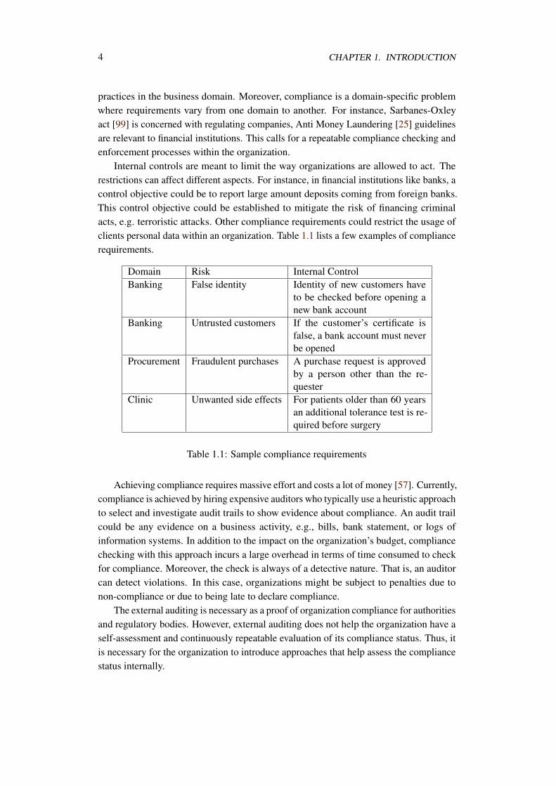
Internal controls are meant to limit the way organizations are allowed to act. Therestrictions can affect different aspects. For instance, in financial institutions like banks, acontrol objective could be to report large amount deposits coming from foreign banks.This control objective could be established to mitigate the risk of financing criminalacts, e.g. terroristic attacks. Other compliance requirements could restrict the usage ofclients personal data within an organization. Table 1.1 lists a few examples of compliancerequirements.
Domain Risk Internal ControlBanking False identity Identity of new customers have
to be checked before opening anew bank account
Banking Untrusted customers If the customer’s certificate isfalse, a bank account must neverbe opened
Procurement Fraudulent purchases A purchase request is approvedby a person other than the re-quester
Clinic Unwanted side effects For patients older than 60 yearsan additional tolerance test is re-quired before surgery
Table 1.1: Sample compliance requirements
Achieving compliance requires massive effort and costs a lot of money [57]. Currently,compliance is achieved by hiring expensive auditors who typically use a heuristic approachto select and investigate audit trails to show evidence about compliance. An audit trailcould be any evidence on a business activity, e.g., bills, bank statement, or logs ofinformation systems. In addition to the impact on the organization’s budget, compliancechecking with this approach incurs a large overhead in terms of time consumed to checkfor compliance. Moreover, the check is always of a detective nature. That is, an auditorcan detect violations. In this case, organizations might be subject to penalties due tonon-compliance or due to being late to declare compliance.
The external auditing is necessary as a proof of organization compliance for authoritiesand regulatory bodies. However, external auditing does not help the organization have aself-assessment and continuously repeatable evaluation of its compliance status. Thus, itis necessary for the organization to introduce approaches that help assess the compliancestatus internally.
1.1. PROBLEM STATEMENT 5
Process models are developed as a means to document the operational activitiesof an organization. With the maturity of workflow systems, process models are thefirst steps to automate the day-to-day business operations. With the guide of thesemodels, organizations can realize how business objectives are achieved, align their ITinfrastructure, estimate resources, people, time and material, required to accomplishprocesses. Thus, a considerable amount of research has been devoted to check severalcorrectness criteria of process models.
With the explicit view business process models provide over business activities,business process models are good candidates to check the effectiveness of establishedinternal controls [65]. This means, business processes are confronted with new correctnesscriteria, imposed by compliance requirements. Unlike classical correctness criteria, e.g.,the different notions of soundness [3, 30, 111, 87] and correct data flow[120, 134],compliance requirements are considered as semantic constraints over the way processesbehave. Compliance requirements vary from one domain to the other. Also, theserequirements can change due to new laws, policies or other types of constraints. As aresponse to the nature of change, new approaches and tools have to be developed wherecompliance rules, are no longer hard coded. Moreover, compliance management is seen asa lifetime process. That is, at different phases of a business process life cycle, compliancefollow up takes different forms. This increases the complexity of the compliance processand in the mean time makes the need for automation stronger.
In addition to business experts and practitioners, we assume the role of a complianceofficer. A compliance officer is responsible for reviewing laws and legislative documents,may be with the help of lawyers, to extract compliance requirements. The complianceofficer establishes internal controls that translate compliance requirements into the orga-nization’s terms; discuss these controls with other people like stakeholders and businessexperts to agree upon internal controls’ relevance and importance.
1.1 Problem Statement
This thesis introduces a compliance management framework and an approach to automatethe checking of compliance requirements against process models. We provide users,compliance officers, with means to express internal controls (compliance rules) and checkthem against business process models.
On the one hand, the automation of compliance checking calls for formal approacheswhere compliance requirements and process models are represented in a mathematicalform. On the other hand, compliance officers need to represent these internal controlsin a way comprehensible by stakeholders and business experts who not necessarily havea sufficient mathematical background to understand mathematical formulas. Thus, onequestion to be addressed by this thesis is how to find a balance between formalizationand readability of compliance requirements?
Usually, organizations maintain their business process models in repositories. A
6 CHAPTER 1. INTRODUCTION
compliance officer not necessarily knows before-hand which process models are subjectto check against which compliance rules. Another question to be addressed is how tohelp the compliance officer correlate internal controls to business processes.
Building on the fact that a compliance officer lacks a priori knowledge about investi-gated processes, upon finding violations to compliance requirements, we are concernedwith the question of how to provide the user with helpful feedback about the violation?Violation explanation is required for many reasons. First, localizing the problematic partof a process helps focus the discussion between compliance officers and business experts.Second, in large business processes, it is tedious and time consuming to manually trackproblematic parts of the process. Third, this helps develop semi automated approaches toresolve the violation. Resolving violations is also a question of interest to the thesis. Thatis, how is it possible to provide automated resolutions of violations? What knowledgeneeds to be explicitly collected in order to achieve automated resolution of violations?
Compliance requirements might affect more than one business process. In the meantime, a business process might be subject to checking against several compliance require-ments. This calls for the separate maintenance of compliance requirements as independentartifacts from process models. This thesis raises the need to maintain compliance reposi-tories as well as the need to maintain business process model repositories.
As compliance requirements might stem from different sources and, yet, are subjectto check against a common set of business processes, it is likely to have inconsistenciesamong these compliance requirements. Inconsistency can be in the form of redundancyor conflicts. This calls for not only correlating compliance requirements and businessprocesses, but also correlating compliance requirements with other compliance require-ments. This thesis addresses the problem of deciding about inconsistency among relatedcompliance requirements as prerequisite to check compliance against business processes.
1.2 Scope of the Thesis
This section sets the scope of the contributions in this thesis. We discuss this scopefrom two points of view. The first viewpoint is concerned with the phases to establishcompliance requirements. The second viewpoint is concerned with the lifecycle of thebusiness processes.
The different phases for compliance requirements establishment span the wholespectrum between the discovery of relevant regulations, standards, etc., to the point ofassessment of compliance to compliance requirements.
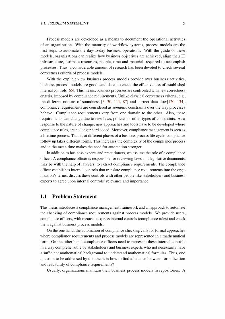
Figure 1.1 depicts the phases of compliance requirements establishment [119]. Thefirst phase is to discover relevant regulations,e.g. SOX [99], standards, e.g., ISO family,contracts, or any other source of information that might require ensuring controls overthe business. Usually these requirements are stated informally in natural language. Thus,an effort has to be done to extract a specific set of compliance requirements to formalizeit. Priorities of compliance requirements vary. Thus, risk assessment has to be conducted
1.2. SCOPE OF THE THESIS 7
Figure 1.1: Phases of compliance requirements establishment
in order to evaluate the threat of not obeying these requirements. Thereafter, internalcontrols are designed in order to realize compliance requirements. As internal controlsstem from different requirements, it is crucial to assess the consistency among theserequirements. At this point, the organization has to assess its compliance status with theseinternal controls. The whole sequence of phases is repeated each time the organization isobliged to adhere to new compliance requirements. Nevertheless, subsequences of thesephases could be executed as well. For instance, due to entering a new market, risk has tobe reassessed and this causes redesign of compliance rules and so forth.
Steps 1-3 are human-centric activities by nature[119]. Human experts, e.g., compli-ance officers, have to identify what is relevant to the organization from the set of lawsand regulations. They have to assess the risk of not obeying these requirements and haveto develop internal controls that detect and/or prevent violations to such requirements.These steps are out of scope of the thesis. Nevertheless, we discuss how our approachhelps users track and link compliance rules to their sources.
The objective of this thesis is to give automated support for the steps 4-6. Modelinginternal controls (compliance rules), checking their consistency and verifying them againstprocess models constitute the scope of the thesis. The assessment of compliance rule,step 6, can be applied to different artifacts within the organization. Business processes,
8 CHAPTER 1. INTRODUCTION
IT-systems or audit trails can all be subject to compliance assessment. This is the stepwhere compliance requirements can be linked to business processes.
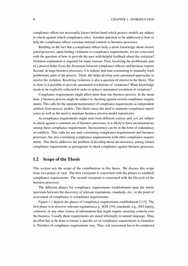
The business process lifecycle is the other scope on the work in this thesis. Figure 1.2shows the different stages of business process lifecycle. Within the design and analysisphase, new process model are identified and created or existing ones are adapted to copewith the new situation. Afterwards, the process model is configured and deployed. Then,a process is enacted on a specific execution platform. The execution might be monitored.Afterwards, executed processes are evaluated against several metrics, e.g., performance.
Design and Analysis
ConfigurationEnactment
Evaluation
Figure 1.2: Business process lifecycle
In this regard, the thesis scope is limited to the design and analysis phase of thebusiness process lifecycle. The support for checking compliance at design time wouldgive a bottom line guarantee of compliance, if the organization is committed to dobusiness in the way stated in process models. Moreover, we are addressing compliancerequirements related to control and data flow aspects of business processes, e.g., activityexecution ordering [159]. We believe that there has been work addressing other aspectsof compliance as will be pointed out in Chapter 3.
1.3 Organization of the Thesis
The rest of the thesis is organized as follows. Chapter 2 discusses compliance aspects thatcan be addressed on the business process model level. Moreover, it sets the requirementsframework that guided the contributions of the thesis. Finally, it gives an overview of theapproach contributed in this thesis.
Related work is discussed in Chapter 3 where other approaches to compliance man-agement of business processes are evaluated against the requirements we established.
Chapter 4 describes the foundations of the work done in the thesis. It describesconcepts and techniques existing in literature and techniques developed by the author ofthe thesis.
Chapters 5-7 describe the contribution of the thesis. The contents of these chapters willbe briefly described in Section 2.3 after the description of our requirements framework,so that the contribution is clear to the reader.
1.4. PUBLICATIONS IN THE COURSE OF THIS THESIS 9
A prototype was implemented as a proof of the contributions of this thesis. Chapter 8elaborates on details of this implementation.
Finally, a critical discussion of our approach is given in Chapter 9 along with openissues for future work.
1.4 Publications in the Course of this Thesis
The following is the list of publications achieved in the course of accomplishing thisthesis:
• Ahmed Awad, Matthias Weidlich, and Mathias Weske. Consistency Checking ofCompliance Rules. In Business Information Systems, volume 47 of Lecture Notesin Business Information Processing, pages 106-118. Springer, 2010.
• Ahmed Awad, Sergey Smirnov, and Mathias Weske. Resolution of ComplianceViolation in Business Process Models: A Planning-based Approach. In RobertMeersman, Tharam S. Dillon, and Pilar Herrero, editors, OTM Conferences (1),volume 5870 of Lecture Notes in Computer Science, pages 6-23. Springer, 2009.
• Ahmed Awad, Matthias Weidlich, and Mathias Weske. Specification, Verificationand Explanation of Violation for Data Aware Compliance Rules. In LucianoBaresi, Chi-Hung Chi, and Jun Suzuki, editors, International Conference on ServiceOriented Computing/ServiceWave, volume 5900 of Lecture Notes in ComputerScience, pages 500-515, 2009.
• Ahmed Awad, Gero Decker, and Niels Lohmann. Diagnosing and RepairingData Anomalies in Process Models. In Stefanie Rinderle-Ma, Shazia Sadiq, andFrank Leymann, editors, Business Process Management Workshops, volume 43 ofLecture Notes in Business Information Processing, pages 5-16. Springer-Verlag,September 2009.
• Ahmed Awad and Mathias Weske. Visualization of Compliance Violation inBusiness Process Models. In Stefanie Rinderle-Ma, Shazia Sadiq, and FrankLeymann, editors, Business Process Management Workshops, volume 43 of LectureNotes in Business Information Processing, pages 182-193. Springer, 2009.
• Ahmed Awad, Sergey Smirnov, and Mathias Weske. Towards Resolving Compli-ance Violations in Business Process Models. In Shazia Sadiq, Marta Indulska, andMichael zur Muehlen, editors, The Impact of Governance Risk and Compliance onInformation Systems (GRCIS), volume 459, pages 18-32. CEUR-WS.org, 2009.
• Ahmed Awad, Artem Polyvyanyy, and Mathias Weske. Semantic Querying ofBusiness Process Models. In Enterprise Distributed Object Computing Conference(EDOC), pages 85-94. IEEE Computer Society, 2008.

10 CHAPTER 1. INTRODUCTION
• Ahmed Awad, Gero Decker, and Mathias Weske. Efficient Compliance CheckingUsing BPMN-Q and Temporal Logic. In Marlon Dumas, Manfred Reichert, andMing-Chien Shan, editors, Business Process Management (BPM), volume 5240 ofLecture Notes in Computer Science, pages 326-341. Springer, 2008.
• Ahmed Awad. BPMN-Q: A Language to Query Business Processes. In ManfredReichert, Stefan Strecker, and Klaus Turowski, editors, Enterprise Modeling andInformation Systems Architecture (EMISA), volume P-119 of LNI, pages 115-128.GI, 2007.
Chapter 2
Requirements for ComplianceManagement
The need to ensure compliance is an ongoing effort where several roles within theorganization are involved. Its ongoing nature calls for automated approaches that alloweffective assessment of the compliance status of the organization. The involvementof people with different backgrounds requires that internal controls are represented indifferent forms in order to allow people to negotiate about them.
Since compliance management is an enterprise wide problem, it is hard to cover allits aspects in a single study. Thus, as was stated earlier, we limit ourselves to compliancemanagement on the level of business processes. Moreover, we are concerned withdesign-time checking of compliance aspects, especially control and data flow aspects.
In Section 2.1 we discuss the different aspects of compliance management on businessprocesses. The section gives an overview on the different aspects, not necessarily checkedonly at design time. Requirements for a design time compliance management for businessprocesses are discussed in Section 2.2.
Based on the requirements discussed in Section 2.2, an overview of the contributionof the thesis is given in Section 2.3. We provide the compliance management framework.Also, we justify our choices of tools and techniques to realize the different componentsof the framework.
2.1 Categories of Compliance Requirements
Compliance requirements affect the aspects that can be modeled in a business process,control flow, data flow, resources, and timing [121, 159].
11
12 CHAPTER 2. REQUIREMENTS FOR COMPLIANCE MANAGEMENT
2.1.1 Control Flow
Compliance rules might require that certain activities must be executed in the course ofa business process. For instance, an anti money laundering requires "reporting a largedeposit transaction by a bank" [25]. In some other rules, dependency between activitiesmust exist. For instance, in an "open account" process, "customer identity checking stepmust precede the step of opening an account". We believe that this type of compliancerules must be checked and enforced at process design time. With a process model correctlydesigned to satisfy these compliance requirements and assuming a faithful execution ofthese processes, it is not possible to violate compliance at run time, unless for exceptionalsituations.
2.1.2 Data Flow
One aspect of compliance is to ensure that business objects are manipulated by processmodels as expected. Also, data and control flow aspects can be mixed to define so-calledconditional flow rules. An example of conditional rule is "If the customer identity checkfails; the customer must be added to a black list". We call this type of compliancerules "conditional" because the dependency between activities depends on conditions.Conditional flow rules are, of course, more expressive than plain control flow rules. Thatis, conditional rules are able to catch finer compliance rules. However, the level of detailsabout data in process models and compliance rules might vary. Thus, it is necessary toguarantee a uniform level of data abstraction at checking time between business processesand compliance rules. This type of rules is also addressed by our framework as theycan be efficiently checked at design time and compliance at process run time can beguaranteed if the execution respects the process model.
2.1.3 Human Resources
Security policies regarding "who will execute what" are seen as compliance requirements.Mainly, the separation of duty principle is of major importance to prevent fraud. That is,the initiator of a request cannot be the same person to approve that request. We believethat sufficient work has been done to verify such human resource constraints at processdesign time [153, 152]. However, we argue that correctly modeling these compliancerequirements is not enough. This is due to the human factor in this situation where runtime monitoring is needed to ensure compliance.
2.1.4 Timing
Service level agreement constraints fall under the fourth category. Also, it might berequired that certain activities must be completed within k units of time. Moreover, somecompliance requirements might stress that customer records must be kept for at least m
2.2. REQUIREMENTS 13
years. Typically, these rules are monitored at run time. Thus, they are out of scope of ourwork.
Collectively, we can notice two differences between compliance rules under thecontrol and data flow categories on one hand and the resource and time categories onthe other hand. Resource and time constraints are of local nature. That is, checking andenforcement is achieved at process design time by explicitly modeling the compliancecontrol. For instance, explicitly modeling a separation of duty between two tasks orexplicitly adding a timing constraint on a specific activity. On the other hand, controland data rules most of the time, as will be shown later, are concerned with dependencieswhich requires the study of the process behavior in order to determine compliance. Thus,in these situations, automated checking is needed to guarantee compliance.
2.2 Requirements
In this section we discuss the set of requirements that guided the contributions of thethesis. To come up with these requirements, we checked several compliance requirementsdocuments, e.g., the guideline for Anti Money Laundering [25]. Also, we integratedrequirements from other proposals for compliance management frameworks [81, 68].The requirements take into consideration the two worlds of compliance rules and businessprocesses that have to be linked together. Also, it is oriented to providing the highestdegree of automation for compliance support. The requirements aim at an intelligentsystems that extends compliance support beyond a yes/no answer about compliance statusof business processes to the support of explaining violations and trying to automaticallyresolve them.
2.2.1 Req. 1: Formal Specification of Compliance Rules
In order to allow automated reasoning about the compliance status of business processesformal approaches have to be adopted. Checking approaches should be selected/developedin the way that provides the highest degree of automation. Moreover, analysis algorithmsmust be efficient. Also, the chosen formalism must be capable of supporting the levelof abstraction needed by compliance rules. Usually, compliance rules address a specificsituation, e.g., dependency between activities, and abstract from other details. On thecontrary, process models are detailed, as they need to be operational, and are more genericthan compliance rules. For instance, a compliance rule might be concerned with thesituation of handling fraudulent insurance claims, while an insurance claim handlingprocess has to deal also with sound claims.
The checking approach must be transparent to the user. That is, the mapping ofbusiness process models and compliance requirements into a specific formalism must beachieved automatically. This allows a wider set of users to participate in the compliancerules modeling and checking.
14 CHAPTER 2. REQUIREMENTS FOR COMPLIANCE MANAGEMENT
2.2.2 Req. 2: Compliance Rules are First Class Citizens
Compliance rules must be explicitly maintained in separate constraints repositories.Although rules are to be checked against processes, they must not be implicitly attachedto and hidden within process definitions. The separate maintenance of rules is needed forseveral reasons.
Firstly, a compliance rule is subject to checking against several process models. So,if compliance rules are replicated as attachments to each related process model, there is achance for inconsistency if compliance rules are updated only in a subset of the relatedprocess models. Thus, compliance rules must be maintained separately and be linkedto process models. Another necessity for separately maintaining compliance rules isthe need to attach arbitrary metadata to them. For instance, metadata about the sourcelegislation, the date from which it is effective, comments from compliance officers andother stakeholders can be attached to compliance rules. Moreover, Compliance rulesmight not be active all the time. For instance, compliance rules might be deactivated.An example would be disabling some internal policies to provide flexibility. All thesesituations call for keeping compliance rules separated from process definitions.
Separately storing compliance rules also allows support for sophisticated maintenanceapproaches like versioning that allows to trace the progress of compliance rules and alsoallows to foresee any future enhancement. Moreover, it is possible to group related rulesto allow further analysis on them, e.g., consistency checking as will be discussed in Req.
3. Also, it is possible to come with complex rules out of simple rules in a dynamic way.For instance if we have three basic compliance rules r1,r2 and r3, we can come up witha complex rules cr1 = (r1∧ r2)∨ r3. In this case, any changes to the basic rules will bepropagated to cr1 automatically, thus, avoiding problems of outdated rule definitions.
2.2.3 Req. 3: Consistency Checking of Compliance Rules
With the possible divergent sources of compliance requirements, it is likely to haveinconsistencies among a set of compliance rules. Also, the human interpretation of juridicdocuments might increase the chance of inconsistencies. Thus, it is necessary to establishmechanisms to decide about inconsistencies among compliance rules. Inconsistency canbe attributed to conflict, redundancy or both. Conflicts among a set of rules indicates thatit is not possible at all to come up with a process model that realizes all of them. On theother hand, redundancy is about having two or more rules describing the same situation.
Without the ability to decide about consistency of a set of related rules, a precioustime and effort could be spent trying to check/enforce conflicting or redundant com-pliance requirements. It might take several cycles of updating process models beforefiguring out that the compliance requirements are conflicting, especially when checks ofconflicting rules are done by different people. This necessitates resolving the conflictamong compliance rules before proceeding to checking them on process models.
Also, it is necessary to establish resolution approaches for conflicts among compliance
2.2. REQUIREMENTS 15
rules. However, not in every case the resolution is automated. One possibility of resolutionis to identify priorities between conflicting rules.
2.2.4 Req. 4: Correlating Processes to Compliance Rules
(Semi) automatic identification of process models subject to checking in a repositoryof business process models is a must. Within large business process repositories, it istedious and error prone to manually scan process models to decide about their relevance tocertain compliance rules. Providing tools and techniques that help systematically accessa process repository and query for processes based on a specific criteria is considered as avaluable aid in the process of compliance management to establish correlation betweenprocesses and rules.
This correlation allows the automated checking of rules against processes. Yet, ina loosely coupled fashion. That is, whenever a rule is changed the compliance officeris informed about process models needed to be checked. Also, it is guaranteed that allprocesses subject to investigation are checked against the same version of the compliancerule. Similarly, a change of the process model determines which rules need to be(re)checked.
2.2.5 Req. 5: Providing Information About Compliance
Req. 1 stated that compliance rules must be expressed in a formal language to automati-cally check whether they are satisfied by a business process. In the current requirement,we are concerned with a more advanced situation. That is, if a process model p is compli-ant with a rule r, the compliance approach must be able to decide about the nature of thecompliance.
Usually, compliance rules are on the form s → q. Where s is the condition of the ruleand q is the consequent. When a rule r is correlated to a process model p, it is requiredthat p will behave in a way that makes s true and thus q must also be true, in order to becompliant. However, if the process p never exhibits s then p is also compliant. In thiscase p vacuously satisfies r. Thus, it is important that the compliance checking approachto inform the user, e.g. compliance officer, if a rule r is vacuously satisfied by a process pas this might help identify logical deficiencies in the design of p. The resolution of thesedeficiencies is out of scope.
2.2.6 Req. 6: Providing Useful Feedback in Case of Violation
The localization of problematic parts of the process models helps business experts focustheir discussion and take corrective actions. Thus, the binary decision about the compli-ance status of a business process to a compliance rule is not helpful enough. Whenever aprocess model fails the compliance checking with a rule, an explanation of the possibleviolation(s) must be reported to the user. The reported violation must be in a form that isreadable to the user who is not necessarily a technical expert. Thus, the explanation must
16 CHAPTER 2. REQUIREMENTS FOR COMPLIANCE MANAGEMENT
be in business terms rather than in technical terms. This complements Req. 1in the sensethat underlying formal checking must be transparent to the user.
The violation explanation approach must be exhaustive. That is, every possibleviolation of a compliance rule must be detected. If only a subset of violations is found,this will necessitate the call for a second round of verification after fixing the so-far-founderror. But, if all violations are guaranteed to be found, they can be fixed in a single round.This exhaustive violation explanation saves the time and effort of business experts andcompliance officers.
The violation explanation procedure should be automatically invoked at the time theverification procedure determines non-compliance. The final result to the user should beeither that the process is compliant, or it is not compliant along with the explanation.
2.2.7 Req. 7: Resolution of Violations (Optional)
It is preferable to suggest remedies to compliance violations when possible. Theseremedies are in the form of process model reforming to be compliant. While resolvingviolations can be seen as a pure human expert’s task, it might be possible to partiallyautomate violation resolution.
In the situation where trivial updates to the process need to be taken to enforcecompliance, automation can relief the expert and let him focus on the more complexsituations. On the other hand, when automated resolution is not possible, the useris informed about what is missing in order to resolve violations. The identificationof missing information can be seen as an aid to estimate the effort needed to restorecompliance. This is especially true in situations where the business objective behind abusiness process contradicts the compliance rule. For instance, providing flexibility ofreceiving money after sending goods against the firm requirement of not sending outgoods before receiving the payment.
Automating violation resolution depends on the domain knowledge. Thus, expertsystem approaches could be used to extract business expert knowledge and encode themin a way that allows their reuse. While extracting the knowledge is out of scope, theencoding of this knowledge should be in a formal and technology independent way. Theformality allows automated reasoning; the technology independent representation allowsthe reuse of this knowledge in different situations and for different purposes.
Suggested remedies must respect correctness and operation-ability of business pro-cesses. This stems from the different natures of rules and processes as discussed earlier.Rules are focused on a specific situation, while processes contain sufficient details to beoperational. The resolution approach must fill this gap. That is, violation resolution mustsuggest remedies in details sufficient for keeping the process operational. In the meantime, the merge of these remedies within the process should keep it consistent and correct.For instance, if a violation can be fixed by inserting some activity in the process model, itis necessary to be sure that all prerequisites for this activity will be present at the activityexecution in order to avoid deadlocks.
2.3. CONTRIBUTION OF THE THESIS 17
2.2.8 Req. 8: Triggering of Compliance Checking
Usually checking is triggered by users. The compliance support system should beproactive in telling the user about the need to (re)check. This requirement is based onReq. 4. Each time a rule or a process is changed, the system may suggest a rerun ofchecking. This allows an instant response to changes in the rule repository or the processrepository and providing a tight follow up on the compliance status of processes.
2.2.9 Req. 9: Graphical Representation of Compliance Rules
While formal representation of compliance rules allows for automated reasoning, it limitsthe accessibility only to technical experts. However, for business people, it is necessaryto discuss about these compliance requirements before putting them into production.Thus, compliance requirements need to be presented in a way comprehensible to businessexperts and stakeholders. On the other hand, discussing compliance requirements intheir juridic form is not preferable as well. In many cases, the terms are ambiguous andare not in the business terms. Thus, an intermediary representation of these compliancerequirements, preferably in business terms, is needed to ensure the highest possibility ofuniform perception and to reduce chances of conflicts.
2.3 Contribution of the Thesis
In this section we layout the contribution of the thesis to come up with an approach forcompliance management of business processes at design time. Our approach realizes theset of requirements discussed in Section 2.2. However, we might assume some techniquesor a level of maturity to exist in order to the proposed approach to work, we discussrelaxations to these assumptions in Chapter 9.
The choice of a verification approach to a large extent controls the level of automationthat can be achieved. Thus, a careful choice of that verification technique will drivethe decision about subsequent steps of, for instance, automated reasoning, violationexplanation and consistency checking.
Of course, another factor to choose a specific verification approach, and thus a specificformalism, is the targeted compliance aspects to be checked. As stated in Section 1.2,we are concerned with static verification of control and data flow compliance aspects ofbusiness processes. In this regard, for a design time checking there are three possibilities:1) simulation 2) model checking 3) logical inference via theorem proving. Simulationeffectiveness is bounded by the experience and skills of the user. Thus, it is a manualapproach that is not guaranteed to cover all possible executions of a process model. Theother two approaches provide a level of automation above simulation.
Model checking [24] algorithms depend on the exhaustive state space search in orderto prove the satisfiability of a property specified as a temporal logic formula. In somecases, model checking performance suffers from state space explosion. On the other hand,
18 CHAPTER 2. REQUIREMENTS FOR COMPLIANCE MANAGEMENT
theorem provers use logical inference techniques to decide whether a property expressedwith first order logic is derivable from the knowledge about the investigated system. Thus,theorem provers do not suffer from the state space explosion problem. However, in manysituations, human intervention is required to help theorem provers reach a decision [102].This intervention is expected from a person who has a deep knowledge about logic andcapable of handling complex logical formulas.
For the case of compliance rules verification, we believe that model checking ispreferable over theorem proving. Firstly, the nature of compliance requirements ad-dressed by this thesis, e.g., dependency between activities, can be well represented astemporal logic formulas. Secondly, the execution semantics of business processes havebeen always interpreted in terms of states which makes the choice of model checkingintuitive. Thirdly, the problem of state space explosion for model checking can be workedaround in a number of ways: 1) Symbolic approaches for representing the state space ofsystems provide a compact way that avoids state explosion. 2) Employing state reductiontechniques based on the verified property. Fourthly, model checking is fully automated.
In the business process management community, process models’ behavioral sound-ness have been heavily studied, e.g. [3, 30]. One benefit is that formal execution seman-tics have been assigned to the different process modeling elements e.g., semantics ofEPCs [137], semantics of BPMN [31], etc. However, these semantics were only con-cerned with control flow aspects. As we are concerned with data access semantics also,we had to provide a formal access semantics that integrates well with existing controlflow semantics. The discussion about process models and their execution semantics isgiven in greater details in Chapter 4.
To define a compliance rule to be checked against a process model via model checking,the user has to represent the compliance rule as a temporal logic formula. It is not possibleto assume that every person involved in compliance management is aware of such complexmathematical notation. Moreover, in Req. 9 "Graphical representation of compliancerules", we argued that compliance rules should be represented in a way readable to auser who is usually more on the business side. In [39, 76] the authors proposed a visuallanguage that allows the users to express compliance rules in a graphical way whileencapsulating the formal property and generating it transparently to the user. We believethat this approach provides a balance between expressiveness and formality on the onehand and ease of use on the other hand. Thus, we will provide the user with a set ofvisual patterns to model compliance rules and an approach to extend these patterns. Theapproach is to define a visual pattern and assign it a temporal logic template. With thisapproach, we have a formal representation of compliance requirements, Req. 1, a visualrepresentation easy to use by the compliance officer and business experts, Req. 9, andwe are able to automatically decide about (vacuous) satisfiability of compliance rules,Req. 5.
To represent a compliance pattern, compliance rule type, we use BPMN-Q [7, 124].Originally, BPMN-Q was designed as a visual language to query repositories of business
2.3. CONTRIBUTION OF THE THESIS 19
process models. BPMN-Q provides a set of abstract concepts, as will be discussed inSection 4.2, that are adequate to express compliance requirements. While BPMN-Q issimilar to BPMN [1] in notation, we explain in Chapter 4 that our approach is indeedgeneric.
With the use of BPMN-Q queries as a means to express compliance rules, we canstore these compliance queries as separate artifacts, Req. 2. Arbitrary metadata describingany kind of attributes of interest to the compliance officer can be attached to queries. Ametamodel describing how to track compliance related artifacts can be found in [64].
To correlate compliance rules to other compliance rules and to business processes,Req. 4, we currently assume a common set of tags that are used to annotate both com-pliance rules, i.e. queries, and business processes. In the simplest form, tags are shorttext that have common interpretation within the organization. For instance, a tag "claimhandling" is interpreted equally both by business expert and compliance officer. Theavailability of common interpretation of these tags is considered as a level of maturitythat we assume to exist within the organization. With the use of tags, we can automatethe correlation between processes and rules, yet, in a loosely coupled way. Any change tothe process, the rule, their tags would flag the need to rerun checks, cf. Req. 8.
As rules can be correlated to each other, it is possible to identify sets of relatedrules by means of finding a common set of tags. To this end, consistency checkingamong them can be conducted, Req. 3. As we said earlier, the choice of the formallanguage determines the level of automation. As temporal logic is the formalism toexpress compliance requirements, consistency checking to a large extent benefits fromwell established approaches in that regard. However, as we will show, these approachesare useless unless domain specific knowledge is well reflected in checking for consistency.
Whenever a compliance rule is not satisfied by a process model, the user must receivean intelligible feedback explaining how the violation occurred, Req. 6. In this regard,we benefit from the querying nature of BPMN-Q and define violation scenarios as antipatterns, in contrast to compliance patterns. For each compliance pattern a set of antipatterns is defined. Each anti pattern is represented also as a BPMN-Q query. When theanti pattern query is structurally matched to the business process, the matching part of theprocess highlights execution paths that caused the violation.
Finally, to suggest remedies, Req. 7, we employ another toolset where we dependon a structural analysis of business processes. Based on this analysis, we devise a set ofcompliance resolution algorithms that depend on automated planning [97].
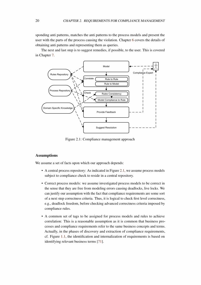
Figure 2.1 summarizes our approach for compliance management. First and foremost,the user, e.g., compliance expert, models the compliance rule by instantiating a compliancepattern. In addition to instantiation, the user assigns a set of tags to the compliancerule. With the tags assigned, the system can identify related compliance rules andbusiness processes respectively. The details of modeling compliance rules, checking theirconsistency and checking them against business processes are given in Chapter 5.
Whenever, a compliance rule checking is negative, the system generates the corre-
20 CHAPTER 2. REQUIREMENTS FOR COMPLIANCE MANAGEMENT
sponding anti patterns, matches the anti patterns to the process models and present theuser with the parts of the process causing the violation. Chapter 6 covers the details ofobtaining anti patterns and representing them as queries.
The next and last step is to suggest remedies, if possible, to the user. This is coveredin Chapter 7.
Figure 2.1: Compliance management approach
Assumptions
We assume a set of facts upon which our approach depends:
• A central process repository: As indicated in Figure 2.1, we assume process modelssubject to compliance check to reside in a central repository.
• Correct process models: we assume investigated process models to be correct inthe sense that they are free from modeling errors causing deadlocks, live locks. Wecan justify our assumption with the fact that compliance requirements are some sortof a next step correctness criteria. Thus, it is logical to check first level correctness,e.g., deadlock freedom, before checking advanced correctness criteria imposed bycompliance rules.
• A common set of tags to be assigned for process models and rules to achievecorrelation: This is a reasonable assumption as it is common that business pro-cesses and compliance requirements refer to the same business concepts and terms.Actually, in the phases of discovery and extraction of compliance requirements,cf. Figure 1.1, the identification and internalization of requirements is based onidentifying relevant business terms [71].
2.3. CONTRIBUTION OF THE THESIS 21
• A common set of activity and business object labels: this is related to the aboveassumption. We assume that whenever a business activity label appears in a processmodel or compliance rule, they reflect the same business semantics. For instance,“Process purchase request” means the same thing for both business process modelerand compliance rule modeler.
• Explicit domain knowledge: Figure 2.1 indicates the importance of domain-specificknowledge in order to automate the checking, explanation and resolution steps.We assume this knowledge to be present and encoded in the way we discuss it inSection 4.4.
In Chapter 9 we discuss approaches to relax these assumptions.

Chapter 3
Related Work
While this thesis is concerned with design-time compliance management of businessprocesses, in this chapter, we widen the scope of related work to include support ofcompliance at the different phases of a business process life cycle. We will extensivelydiscuss approaches concerned with design-time compliance management and will evaluateeach against compliance requirements introduced in Section 2.2. Section 3.1 discussesother compliance management frameworks proposed for business processes. Design-timecompliance management approaches are detailed in Section 3.2. Section 3.3 discussesapproaches for monitoring the adherence to compliance requirements at process execution.Compliance auditing is discussed in Section 3.4.
3.1 Compliance Management Frameworks
In [161] authors discussed how risk management can be integrated in the business processmanagement life cycle. The authors have identified a set of risk factors and definedgeneral strategies to deal with them. Noncompliance to regulations is a risk factor. Thus,it is necessary to establish measurements for risk of that type, to document it, and toestablish control objectives that ensure compliance and avoid that risk. In this sectionwe give an overview on compliance management frameworks that addressed the issue ofdocumenting and tracking compliance requirements. Note that we are not concerned withhow control objectives are realized or checked; rather, we focus on the concepts of risk,regulation and internal controls.
In [121] authors introduce the notion of a control directory as a means to managecompliance requirements. Moreover, the authors correlate the control management lifecycle with the business process management life cycle. Within a control directory, eachentry is described by the control requirement, the risk the organization takes in caseof violation and the internal control that must be established in order to be compliant.The work in [95, 94] extends the work discussed above by describing the different roles
23
24 CHAPTER 3. RELATED WORK
involved in compliance management, namely business process expert, compliance expertand the external auditor. Moreover, the authors discuss different recovery actions in caseof violation that can be attached to each control objective. Finally, the authors classifythe control objectives into patterns that they claim to occur frequently in regulations. Theframework is oriented to runtime monitoring of control objectives. The authors agree withour view about the need to maintain a separate control directory, what we call compliancerules repository. However, the framework does not discuss the need to develop mechanismto decide inconsistency between related compliance requirements, Req. 3. While theframework supports run time compliance management, Req. 6 and Req. 7 regardingproviding useful feedback and supporting automated resolution of violations are notrelevant. The framework puts the task of correlating processes to compliance rules totallyon the human side, Req. 4. The framework proposes the formal contract language (FCL)to represent compliance rules. The language, as the name tells, is a technical one. Webelieve that the use of technical representation only limits the chance to argue about therules.
[127] discusses an ontology based approach to represent both processes and com-pliance requirements. The approach classifies compliance requirements into syntactic,semantic and pragmatic. The compliance checking then is reduced to the problem ofchecking whether the process ontology instance realizes the compliance ontology. Thework in [69] follows a similar approach. The two frameworks, thus, support Req. 1,which allows to formally reason about compliance. Also, developing compliance specificontology could be seen as a satisfaction of the separate maintenance of compliance rules,Req. 2. However, it is not clear whether the frameworks allow to attach metadata totrack the sources of the compliance requirements and risk factors attached to them. Theframeworks support neither providing useful feedback in case of violation, Req. 6, norautomated resolution of violations, Req. 7. However, consistency issues among compli-ance rules, Req. 3, can be identified while building the compliance ontology. Correlationbetween processes and rules, Req. 4, is achieved on the ontology level.
Authors of [155] provide a methodology to semi automatically extract and documentcompliance requirements. To extract compliance requirements, natural language process-ing techniques are used to identify relative terms. Later on, the extracted terms are putinto a taxonomy. This framework is oriented to support the automation of compliancerequirements extraction from legislative documents. Thus, it does not intersect with thescope of this thesis. However, consistency checking mechanisms can be applied early atthat stage.
[96] discusses the challenge imposed on organizations to come up with internalcontrols to ensure that business operations comply with requirements. The internalcontrol is itself a process that includes: identification of significant accounts, definition ofcontrol objectives, Req. 2, identification of relevant processes, Req. 4, and risks behindnot obeying them. Challenges of compliance management can be attributed to two factors.First, the realization and testing of internal controls is known to be an expensive and a
3.1. COMPLIANCE MANAGEMENT FRAMEWORKS 25
time-consuming operation. Second, the compliance requirements are usually very highlevel and without any recommendation on how to realize these requirements. The authorsdiscuss high level concepts like, a control objective, a business process and a risk. Theauthors relate these concepts to each other. However, the authors do not discuss how orwhen to check compliance rules against business processes. Moreover, the authors donot propose a specific formalism to express compliance rules, thus, requirements Req.
1, Req. 6, Req. 9 and 7 were not addressed. Moreover, consistency checking amongcompliance requirements were not addressed.
The work in [69, 70] discusses a framework to define and integrate compliancerequirements within the organization by means of policies. As compliance is a verticalconcern, i.e., it is approached at different levels of details, the authors propose the useof ontologies as a means to control the level of abstraction needed for both businessprocesses and compliance requirements. As compliance requirements are abstract, e.g.,laws, the authors propose to integrate them in the organizations goals and strategies.This will reflect compliance requirements on finer-grain levels like operational processes,business objects and security policies. The authors suggest the use of business rules asa means to realize policies and to monitor the enforcement of compliance requirementson process models and on process execution. To this end, consistency checking amongcompliance rules, Req. 3, the need to explain violations and provide useful feedback,Req. 6 and support for suggesting resolutions to violations, Req. 7 were not recognizedby that framework.
Ly et al. [81, 84] introduce SeaFlows, a compliance management framework sup-porting so-called lifetime compliance. The framework points out the need for a separateconstraint repository. SeaFlows distinguishes itself in support to design time validationand the support of controlling instance adaptation at runtime. To support design timevalidation, SeaFlows allows more than the binary yes/no decision about compliance. Thatis, the framework can identify full compliance, definite violation and conditional violation.The framework supports providing the user with textual description of violations. How-ever, it is not clear how the framework supports consistency checking among compliancerules, Req. 3. Moreover, the correlation of rules to processes is left to humans with noautomated support, Req. 4.
In [19] the authors develop an enterprise-wide approach to help assess risk and achieveagreement among different stakeholders about regulations and the controls to be createdto realize these regulations. The authors determine the relationship between the numberof regulations, disagreement between stakeholders, risks, controls, costs and compliancedegree. Based on these terms and their relationships, authors came up with a model totrack compliance by means of identifying business units that have to show complianceto certain regulations. To achieve compliance, control activities are established. Thesecontrols are realized via IT solutions. The framework focuses on achieving agreementamong different stakeholders regarding a specific regulation on a high level. Thus, noneof the compliance requirements discussed in Section 2.2 are addressed by that framework.
26 CHAPTER 3. RELATED WORK
Service oriented architecture (SOA) is seen as an implementation architecture forbusiness processes. To ensure governance of compliance, the compliance-driven models,languages, and architectures for services (COMPAS) [2] project aims at providing alife-time support for compliance for processes implemented as services. The overallarchitecture and the research objectives of the project is described in [27]. To supportcompliance at process design time, COMPAS follows a compliance-driven approach.That is, process fragments are designed to be compliant with rules of interest. To comeup with operational processes, process fragments are enriched with sufficient details thatmake them operational and are deployed. At runtime, compliance is monitored by meansof logging events from both processes and execution engines. Later on, these events areaudited to assess the compliance state of the organization.
Evaluating COMPAS against our requirements discussed in Section 2.2, we can seethat Req. 1, formal specification of compliance rules, is not considered as the frameworktends to build process fragments that are compliance-driven. However, due to the changingnature of compliance requirements, it is necessary to identify the compliance status ofalready developed processes to new requirements. Consequently, Req. 6, providing usefulfeedback, and Req. 7, resolution of violation, are not addressed as the framework tendsto compliance-driven process design. Also, the notion of consistency checking betweendifferent compliance rules is not addressed, Req. 3.
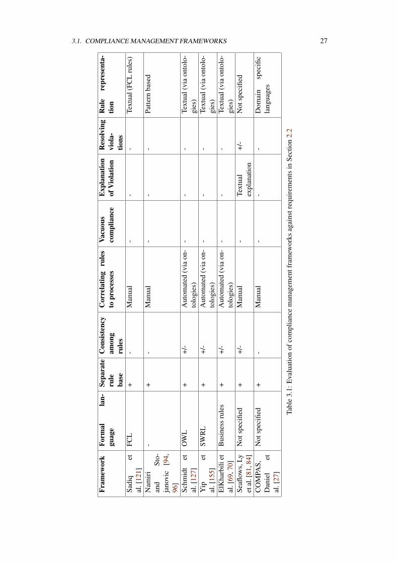
Table 3.1 summarizes the evaluation of the above mentioned frameworks against ourrequirements for a compliance management framework. For each approach we describethe formal language being used to represent compliance rules, the support for separaterule base, the awareness of the need to check consistency, the approach to correlaterules to processes, the ability to report about vacuous compliance, the ability to explainviolations, the ability to suggest remedies to violations and the representation of rules tousers. The use of +,+/-, or - indicates full, partial or lack of support to a specific feature.
3.1. COMPLIANCE MANAGEMENT FRAMEWORKS 27
Fram
ewor
kFo
rmal
lan-
guag
eSe
para
teru
leba
se
Con
sist
ency
amon
gru
les
Cor
rela
ting
rule
sto
proc
esse
sVa
cuou
sco
mpl
ianc
eE
xpla
natio
nof
Vio
latio
nR
esol
ving
viol
a-tio
ns
Rul
ere
pres
enta
-tio
n
Sadi
qet
al.[
121]
FCL
+-
Man
ual
--
-Te
xtua
l(FC
Lru
les)
Nam
iri
and
Sto-
jano
vic
[94,
96]
-+
-M
anua
l-
--
Patte
rnba
sed
Schm
idt
etal
.[12
7]O
WL
++/
-A
utom
ated
(via
on-
tolo
gies
)-
--
Text
ual(
via
onto
lo-
gies
)Y
ipet
al.[
155]
SWR
L+
+/-
Aut
omat
ed(v
iaon
-to
logi
es)
--
-Te
xtua
l(vi
aon
tolo
-gi
es)
ElK
harb
iliet
al.[
69,7
0]B
usin
ess
rule
s+
+/-
Aut
omat
ed(v
iaon
-to
logi
es)
--
-Te
xtua
l(vi
aon
tolo
-gi
es)
Seafl
ows,
Lyet
al.[
81,8
4]N
otsp
ecifi
ed+
+/-
Man
ual
-Te
xtua
lex
plan
atio
n+/
-N
otsp
ecifi
ed
CO
MPA
S,D
anie
let
al.[
27]
Not
spec
ified
+-
Man
ual
--
-D
omai
nsp
ecifi
cla
ngua
ges
Tabl
e3.
1:E
valu
atio
nof
com
plia
nce
man
agem
entf
ram
ewor
ksag
ains
treq
uire
men
tsin
Sect
ion
2.2
28 CHAPTER 3. RELATED WORK
All frameworks recognize the need to separately maintain compliance rules. However,only a subset discusses the need to establish consistency checking mechanisms amongthem. Depending on the formalism for capturing compliance rules, consistency checkingcan be gained. For instance, using business rules, one can benefit from well establishedapproaches for consistency checking [49].
None of the approaches envisioned the support for vacuous satisfiability, violationexplanation and violation resolution except for the SeaFlows [84], where the frameworkprovides textual explanation of compliance violation. Textual explanation might be hardto reflect, by the user, on the process level, in case the process is large or that it hasmultiple appearances of the violation. In the latter case, there is a threat of incompletenessof identifying problematic parts of the process.
Most of the approaches do not distinguish between the formal representation ofthe rule and the representation for business users. This is a limitation as it hinders theunderstandability of non-technical users. When rules are negotiated on a business level,compliance expert has to provide a manual mapping from formal representation to anotation understood by business people.
3.2 Design Time Compliance Checking
Process design time compliance can be categorized into compliance-driven process designand compliance verification. Compliance-driven design aims at enforcing complianceand ensuring it while a business process is being designed. In compliance verification,processes are designed independently from compliance awareness and are checked laterfor compliance.
Compliance-driven design guarantees violation prevention as both the business expertand the compliance expert are involved in that step. However, compliance-driven processdesign cannot be fully automated. This approach is useful in specific cases whereprocesses are derived from a certain specification, e.g., business contracts, and are keptfor a predefined duration, e.g., the duration of a business contract.
On the other hand, compliance verification allows more flexibility and a higher degreeof automation. Process design and compliance checking are decoupled. This allows toautomate and repeat the check each time a compliance requirement is added or changed,or a process is added or changed. However, this approach requires a higher degree ofmaturity in order to automate in terms of means to correlate compliance requirements tobusiness processes. For this approach, automated verification tools can be employed toaccelerate the checking process and have accurate results. However, still the resolution ofviolation is to a large extent on the human side.
In the rest of this section we will explore literature following the above classifica-tion. We start by approaches supporting compliance-driven design and then we discussapproaches for compliance verification. For each approach we describe the language or
3.2. DESIGN TIME COMPLIANCE CHECKING 29
tool used to represent the compliance rules, the reasoning approach, and the category ofcompliance requirements, cf. 2.1, addressed.
3.2.1 Compliance-driven Design
Goedertier and Vanthienen introduced an approach to support compliance-driven businessprocess design in [50]. The authors propose the use of business rules as a means toguarantee compliance with regulations in a flexible way. Business rules reflect therequirements imposed by either external regulations or internal policies. Thus, there isno need to hard code these requirements directly in the process control flow. To expresspolicies, the authors developed "Process ENtailment from the ELicitation of Obligationsand PErmissions" (PENELOPE) as a declarative language to capture obligations andpermissions imposed by business policies in the form of temporal deontic expressionsthat are focussed on sequencing and timing constraints between activities in a businessprocess. To guarantee a compliant process, the authors provide an algorithm that generatesa compliant process model from a set of PENELOPE rules. However, the authors clearlyindicate that the generated compliant process model is not intended for execution; ratherit is intended as an aid to the user to verify executable processes against it. The approachfocuses on compliance with control flow aspects. We believe that the generation of aprocess template is an unnecessary step. Processes could be verified directly against rulesin PENELOPE. Nevertheless, PENELOPE can identify conflicts among rules, Req. 3.
Another approach to support compliance-driven design is presented by Milosevic etal. in [92, 93] where authors use the formal contract language (FCL), introduced in [52],to express contract permissions, obligations and prohibitions as a set of FCL rules. Thegeneration of compliant business processes is achieved in a progressive manner. At theabstract level, interactions among business partners of the contract are identified. In thenext step, internal details for each partner’s process are added. These details depend onthe activities mentioned on the partner’s side in the business contract. The authors claimto cover the four different aspects of compliance for business processes, cf. Section 2.1.This is achieved via annotating individual tasks within business processes with predicatesdescribing each aspect. For instance, if a task duration is not allowed to exceed 3 days;it is annotated with predicate max_duration(task,3,days). The annotation ismeant to help in monitoring the generated processes at run time.
In the field of service composition, a framework for guiding service compositionsbased on PROPOLS [55] proactively suggests next step activities in a composition inorder not to violate temporal business rules. While building a service composition, e.g.a business process, is considered as a human task. PROPOLS interactively suggests,based on predefined temporal business rules, to insert, delete and/or reorder activitiesto be compliant. Design mistakes, i.e., contradicting to the business rules, are identifiedon the fly and the designer is informed about the error. To achieve this, a finite stateautomata (FSA) is derived from the set of temporal business rules and the currentlydeveloped process schema. Thus, deviations and possible future moves can be identified.
30 CHAPTER 3. RELATED WORK
The approach focuses on control flow aspects regarding sequencing and occurrences ofactivities. While it is beneficial to proactively guide the designer, the in-progress modelchecking would be of too much overhead regarding processing time to reconstruct theFSA with each update made to the process model. The algorithm to suggest valid nextsteps depends on traversing all paths within the partially developed process FSA until thecurrently selected activity. This incurs a huge overhead as this step is repeated with eachinsertion of a new activity. For suggesting remedies to violations the same approach oftraversing process FSA is employed to identify erroneous paths. However, these paths areidentified on the state level rather than on the process structure level, in contrast to Req.
6. Moreover, the performance of path finding will degrade severely with the existenceof concurrent paths within the process definition. Additionally, the suggested remediesare bound only to the knowledge encoded in the business rules. However, there might beother activities needed to be inserted or deleted to keep the business process operational.The need for this domain knowledge is not recognized by the approach, we elaboratemore on that in Chapters 4 and 7. In [156, 157] the authors extend the use of PROPOLSto a semi-automatic compliance-driven business process design.
During the execution of business processes, data elements are manipulated to deter-mine next steps. In general, business processes manipulate business objects, e.g., order,insurance claim. These objects are described, among other aspects, by their allowedstates and transitions among them. To this end, Kuster etl al. [74] describe an approachto generate business process models that are compliant with business objects life cycles.This is useful as usually the definition of object life cycles are driven by organization’sinternal policies and external regulations. To generate compliant processes, individualactivities in a process are the means to bring a business object from one state to theother. The generated process models are guaranteed to leave the data objects in one ofthe prescribed final acceptable states. However, the approach is not fully automated as incase of several input object life cycles, synchronization points among them have to bedefined manually.
Schleicher et al. [125] propose the preparation of process templates that are implicitlycompliant. Later on, these templates are modified by process experts to adapt them tocertain business needs. To ensure compliance, the adapted templates have to be recheckedfor compliance to assert that no violations are possible due to modifications made by theprocess expert. The authors devote an algorithm to ensure compliance after insertingdetails in the process template to be operational.
Evaluation
Most of the compliance-driven approaches aim at generating process templates that arecompliant with certain regulations. These templates are adapted by users for certainbusiness objectives by means of adding more details to make them operational. Tothis end, a posteriori checking is needed to ensure that the business processes are stillcompliant and no violation is introduced due to an unintentional breaking of compliance
3.2. DESIGN TIME COMPLIANCE CHECKING 31
by a designer. Also, each time regulations change there is a need to a posteriori check toensure compliance. Thus, we believe that compliance-driven process design is useful inspecific cases where processes can be fully derived from a specification, like a businesscontract. Otherwise, there is always a need to recheck.
3.2.2 Compliance Verification
In [39, 40, 41], Forster et al. proposed the Process Pattern Specification Language (PPSL)as an approach to visually express quality, compliance and constraints regarding theprocess behavior. PPSL is an extension of UML Activity Diagrams [100] that extendsedges with the <<after>> stereotype to indicate that two activities are not necessarilyare required to be in strict order. Moreover, they are able to express complex constraintswith all types of logical connectors. To verify properties, PPSL patterns are translated intotemporal logic that are model checked against the process model. Execution semanticsof process models are given via so-called dynamic metamodeling [131, 36] which in away is similar to the token flow semantics of Petri nets. The approach focuses on controlflow aspects of compliance rules. PPSL uses temporal logic as a formal background,cf. Req. 1. Also PPSL patterns are visually represented in way close to that of UMLActivity Diagrams, Req. 9. This gives a great chance for business expert to define andargue about compliance requirements. From an expressiveness point of view, patternsare not capable of expressing negation. That is, certain activities must never be executedwhen other activities have already been executed. Moreover, the approach is limited todefining rules concerning control flow aspects only. Also, no support is given beyondverification. That is, there is no helpful feedback given to the user in case of violation, cf.Req. 6. Let alone the suggestion of remedies to violation, Req. 7.
Taking business contracts as the source for compliance requirements, the authorsin [53] used FCL to formally measure the compliance between a business contract anda business process. As stated earlier, it is possible to express obligations prohibitionand permissions within a FCL rule. Moreover, it is possible to express several levels ofexception handling when the basic behavior is violated by the business process. FCL isfurther used in [80, 79] to help business process designer quantitatively assess the degreeof compliance of a process with a rule. Based on a compliance rule, a process can beeither ideal, sub-ideal or non-ideal. To reason about the idealism of a process against anFCL rule set, the authors in [54] provide an algorithm that follows a theorem provingapproach to verify the rule against the process. To reach this, activities with a processare annotated with certain effects [51] upon which the algorithm reasons. The currentreasoning algorithm does not support loops within process models. A similar approach toverify contract regulated service composition can be found in [77]. The level of idealismreported for a business process against a rule can be seen as a support for explaining thecompliance status of a business process, Req. 6. However, the approach does not supportthe notion of violation resolution, Req. 7. Moreover, FCL rules are represented purely astextual formulas. This limits to a great extent the ability of business experts to understand,
32 CHAPTER 3. RELATED WORK
develop and argue about these compliance requirements.
Approximate compliance checking for annotated process models is discussed in [148,58]. The authors argue that verifying a process against a compliance requirement isan NP-hard problem and thus approximate approaches are needed as a work aroundthat limitation. The authors provide an approach that is in general neither sound norcomplete. That is, in some cases they are able to find some of the violations. In someother cases they cannot identify non-compliance. Also, the verification algorithms arelimited to process models without loops. The verification is in a form of theorem provingand thus needs to propagate the effects of activities throughout states. One merit ofthat approach is the ability to trace back from the violating state to the activity thatcaused the violation. However, this is only useful to compliance rules of local nature,e.g., restrictions on resource allocations like separation of duty. However, violationto execution ordering compliance rules cannot benefit from this diagnosis feature. Theapproach seeks compliance rules with effects local to specific activities within the process.
Another approach that addresses compliance verification using ontologies is presentedin [56]. The paper describes a prototypical implementation of checking compliance ofbusiness processes, annotated with ontological terms, against business rules capturingcompliance requirements. Upon violation, the tool is able to highlight the activity thatcaused the violation. The approach addresses compliance issues related to existence ofspecific activities within the process. Compliance requirements related to the executionordering between activities are not covered. There is no support for resolving violations.
In [76], a formal approach based on model checking was given to check for compli-ance of processes defined in BPEL against constraints defined in the Business PropertySpecification Language (BPSL) that are translated to linear temporal logic. The approachsupports both control and data flow aspects for compliance checking. Similar work thatverifies BPEL processes is described in [158] where authors propose their own languagePROPOLS to capture patterns to be checked against a business process. Upon a violationdetection, the authors in [76] show the user execution traces on the state level that causedthe violation. As known from standard model checking algorithms, these execution traces,also called counter examples, are automatically given by the model checker. In compar-ison to Req. 6, providing useful feedback in case of violation, the state-level counterexample is not useful to the user as it is presented in technical terms. Moreover, counterexamples are not complete, as they report the first met violation only, we elaborate moreon that in Chapter 6. The requirement to provide remedies for violation is not addressedby that work. Moreover, BPSL patterns seem not to support modeling negation.
Ly et. al [82, 83] discuss an approach for managing and verifying semantic con-straints within adaptive process management [150, 139]. The authors describe semanticconstraints as a form to express compliance rules. The approach extends earlier work onsupporting adaptivity and change propagation from process models to instances, and viceversa, from a syntactical correctness [112, 114] to a semantical one. The extension is inthe form of formalizing and integrating domain knowledge within process management
3.2. DESIGN TIME COMPLIANCE CHECKING 33
systems. To verify constraints, the authors depend on execution traces. An executiontrace is a finite sequence of events. An event corresponds to the completion of a task. Theconstraints are checked against these traces for satisfiability. The approach is concernedwith control-flow aspects of compliance. The approach for verification is limited toprocesses without loops. Also, the need to provide useful explanation of violation is notsupported. Let alone the suggestion of remedies.
In [72], the authors present an approach to model business processes and verifytheir behavior against compliance rules based on a formal language called Reo. Processmodeling constructs, e.g., activities, choice, parallelism, are mapped to Reo circuits. AReo circuit is a sort of logical circuit. Constraint automata (CA), a special type of finitestate machines, are derived from Reo circuits in order to enable the reasoning about theprocess behavior. The approach is claimed to cover all aspects of compliance modelingby means of utilizing special extension of the (CA) for the specific aspects, for instanceTCA extension can be used to address compliance rules related to timing and deadlinesof activities. Evaluating the approach against our requirements, the automated supportis limited to verification. That is, there is no support for providing useful informationin case of violation. Also, the compliance rule is assumed to be written directly in therespective formal language used for verification. So, a user-friendly representation is notconsidered. Also, there is no means to support resolution violation.
In [46] Ghose and Koliadis propose an approach to check compliance of businessprocesses and to resolve violations. In order to determine the compliance status of abusiness process, activities within the process must be annotated with their immediateeffects. An annotated process is then mapped to so called semantic process networks(SPN). SPN is a directed graph that serves as an input to the verification algorithmagainst compliance rules. Authors provide their own algorithms to verify propertiesrelated to execution ordering of activities. To resolve violations, heuristics are used. Theapproach is focused on control-flow aspects. Also, the approach is not fully automatedas a business analyst is required to manually accumulate activities’ effects throughoutthe whole process model, in contrast to automated propagation discussed in [148]. Thiscumulative propagation of activity effects is needed by the verification algorithms since itis designed to check compliance locally at each single activity. Of course, with mediumto large process models, the chance to forget or to mis-propagate the effects is verylikely. Thus, the result of verification cannot be trusted. While explaining violations isnot addressed. There is a limited support for resolving violations by suggesting adding,removing, or reordering of activities to gain compliance. These suggestions do not takeinto consideration dependencies between activities. For instance, the approach mightsuggest to reorder activities A and B in a way that A executes after B while there is adata dependency from B on A. In such case, reordering will make the process compliantbut will not be operational since the execution will deadlock due to unfulfilled data inputsof B.
Kumar and Lui in [73] address the resource aspects of compliance. Using a pattern

34 CHAPTER 3. RELATED WORK
based approach, the authors express role based access controls to tasks in a process model.The authors discuss how variants of the separation of duty principle can me modeled inProlog and verified against process models, where activities are annotated with roles thatwill perform them. A similar work is discussed in [153] where Wolter et al. provide anextension of BPMN [1] that allows the user to visually specify task based authorizationconstraints. In [152] Wolter et. al use model checking to verify whether a process modelsatisfies security constraints like separation and bind of duty. In [89] Mendling et. alstudy the different ways to express separation of duty constrains using BPEL4People [4].
Table 3.2 summarizes our evaluation of compliance verification approaches. Theevaluation is based on satisfaction of compliance requirements discussed in Section 2.2.
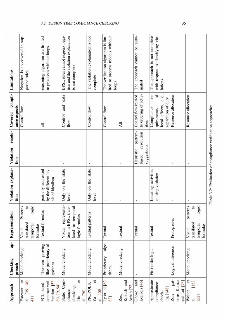
3.2. DESIGN TIME COMPLIANCE CHECKING 35
App
roac
hC
heck
ing
ap-
proa
chR
epre
sent
atio
nV
iola
tion
expl
ana-
tion
Vio
latio
nre
solu
-tio
nC
over
edco
mpl
i-an
ceas
pect
sL
imita
tions
Fore
ster
etal
.[3
9,40
,41
]
Mod
elch
ecki
ngV
isua
lPa
ttern
str
ansl
ated
tote
mpo
ral
logi
cfo
rmul
as
--
Con
trol
flow
Neg
atio
nis
noco
vere
din
sup-
port
edru
les.
FCL
-bas
edco
ntra
ctve
ri-
ficat
ion
[53,
80,7
9,54
]
The
orem
prov
ing-
like
prop
riet
ary
al-
gori
thm
Text
ualf
orm
ulas
part
ially
addr
esse
dby
the
diff
eren
tlev
-el
sof
idea
lism
-al
lre
ason
ing
algo
rith
mar
elim
ited
topr
oces
ses
with
outl
oops
Stat
icC
om-
plia
nce
chec
king
,L
iuet
al.[
76]
Mod
elch
ecki
ngV
isua
lre
pres
enta
-tio
nin
BPS
Ltr
ans-
late
dto
tem
pora
llo
gic
form
ulas
Onl
yon
the
stat
ele
vel
-C
ontr
olan
dda
taflo
wB
PSL
rule
sca
nnot
expr
ess
nega
-tio
nan
dth
evi
olat
ion
expl
anat
ion
isno
tcom
plet
e
PRO
POL
S,Y
uet
al.[
158]
Mod
elch
ecki
ngTe
xtua
lpat
tern
sO
nly
onth
est
ate
leve
l-
Con
trol
flow
The
viol
atio
nex
plan
atio
nis
not
com
plet
e
Lyet
.al
[82,
83]
Prop
riet
ary
algo
-ri
thm
Text
ual
--
Con
trol
flow
The
veri
ficat
ion
algo
rith
mis
lim-
ited
topr
oces
sm
odel
sw
ithou
tlo
ops
Reo
,K
okas
han
dA
rbab
[72]
Mod
elch
ecki
ngTe
xtua
l-
-A
ll
Gho
sean
dK
olia
dis
[46]
-Te
xtua
l-
Heu
rist
icpa
ttern
-ba
sed
reso
lutio
nsu
gges
tions
Con
trolfl
owre
late
dto
orde
ring
ofac
tiv-
ities
The
appr
oach
cann
otbe
auto
-m
ated
App
roxi
mat
eco
mpl
ianc
ech
eck-
ing
[148
]
Firs
tord
erlo
gic
Text
ual
Loc
atin
gac
tiviti
esca
usin
gvi
olat
ion
-C
ompl
ianc
ere
-qu
irem
ents
oflo
cal
effe
cts,
e.g.
,se
para
tion
ofdu
ty
The
appr
oach
isno
tco
mpl
ete
with
resp
ect
toid
entif
ying
vio-
latio
ns
Rol
epa
t-te
rns,
Kum
aran
dLu
i[7
3]
Log
ical
infe
renc
ePr
olog
rule
s-
-R
esou
rce
allo
catio
n
Wol
ter
etal
.[1
53,
152]
Mod
elch
ecki
ngV
isua
lpa
ttern
str
ansl
ated
tote
mpo
ral
logi
cfo
rmul
as
--
Res
ourc
eal
loca
tion
Tabl
e3.
2:E
valu
atio
nof
com
plia
nce
veri
ficat
ion
appr
oach
es
36 CHAPTER 3. RELATED WORK
3.3 Runtime Compliance Monitoring
In this section we give an overview of business process compliance monitoring at processruntime. With monitoring we mean instant monitoring of running process instances.Monitoring takes place by a process execution engine that notifies interested agents aboutthe occurrence of specific events during the process execution.
A business contract defines the duties and the rights of the contracting parties. Inreal life, violations are subject to penalties. In an e-business environment it is crucial todefine and monitor the satisfaction of so-called e-contracts. [91, 52] discuss the problemof following up the execution of e-contracts. One of the mechanisms it discusses is themonitoring of contract execution. By monitoring of significant events, the comparisonof actual behavior to the expected behavior is possible. In case of violation, severalresolution mechanisms are offered depending on the severity of the violations. Forinstance, a notification can be used to alert contract participants about possible upcomingviolations, e.g., in contract between an enterprise and an Internet service provider theservice might be allowed to fail no longer than 4 hours a week; otherwise ISP is subjectto penalties. In this case, a contract execution monitor might send reminders for theISP if the 4 hours allowance is about to expire. When a deviation takes place, i.e., thenotification did not help prevent that deviation, mediation mechanisms try to find anagreement between contracting parties in order to put contract execution back into order.Finally, arbitration is the step to do when no mediation possible. Similar approaches canbe found in [62, 116, 6].
In [149], Weigand et al. similarly take business contracts as the basis to align work-flows of partner enterprises into a virtual workflow for the virtual enterprise. The virtualenterprise is modeled using a component definition language (CDL). Each componentrepresents a partner. Later on, the workflow of each enterprise is linked to the businesscontract. Thus, a contract defines the legal interactions between components. To ex-press the mutual commitments among parties, business objects are used to describe thesemantics of cooperation in business terms, e.g., Customer, Order. To work on thesebusiness objects, business tasks are defined in a way that accesses and transforms theseobjects. Finally, business tasks are assigned to roles within organizations and their orderof execution is defined, the workflow. To monitor the execution and adherence to thebusiness contract, control workflows are defined. Control workflows define the sequenceand direction of exchanged messages, according to the contract. Thus, a global contractobject coordinates the execution of the various cooperating workflows. Although theapproach provides a practical solution for virtual enterprises, the authors did not illustratewhich partner owns the contract object.
Giblin et al. [47, 48] propose REALM as a metamodel to express compliance policiescovering all aspects of compliance discussed above. A policy is a rule set that has a scopeof applicability. Rules are expressed by means of real-time temporal object logic. Thisgives expressiveness not only to capture ordering between events; rather, the actual timesof their occurrences. This is necessary to express timing constraints, e.g., an activity must
3.4. COMPLIANCE AUDITING 37
not take more than two days. In addition to enforcing these rules on process definitions,they are monitored at runtime. This is important for time constraints, as design timeverification might not be sufficient.
Ontology languages are used by ExPDT [63] to express privacy compliance rules.With ExPDT, security policies concerning both data and access to them by businessprocesses can be expressed. The language seems to cover three aspects of compliance.That is, one can express a ExPDT rule indicating conditions on the user, the data andthe action taken in the business process. The rules are monitored at runtime to enforcecompliance.
The work in [78] discusses the achievement of IT-controls as means to monitorcompliance of SOA-based business systems. The IT-control is a software artifact that caninteract with automated business processes. The approach focuses on security relatedcontrols. To enable monitoring, the authors propose an architecture that extends a SOA bycomponents for signaling and monitoring events caused by services, for their aggregationand analysis with respect to control objectives
3.4 Compliance Auditing
Usually, the proof of compliance of some organization to regulations is done by anexternal auditor. The external auditor randomly collects, based on experience, audit trailsand logs from the different sectors of the organization for inspection. This step is usuallymanual and its duration depends on the auditors team, their experience and the maturityof the organization. However, it is possible to speedup this step by providing automatedtools that scan system logs, especially process execution engines, to collect evidencesabout the compliance status of the company.
Process mining [135] is an approach to synthesize process models out of executionlogs. To this end, process mining enables organizations to assess the way their processeswere actually executed. Based on the extracted processes, auditing can be automated.In [140], Aalst et al. provide an automated approach to detect violations based onworkflow logs. Audit checks are formalized in linear temporal logic (LTL) formulas thatare model checked against the mined processes. The approach supports the check ofcontrol flow aspects of compliance.
The work in [141] uses process mining to discover anomalous process executionregarding security constraints. Security constraints are interpreted as requirements tohave certain activities executed in a certain order. It is a two-step approach. The firststep is to mine an acceptable log. The result of the step is a structured workflow net.To discover anomalous executions, the second step, logs of newer process instances arechecked for conformance against the mined workflow net. Although the paper assumesthat logs are described not only in terms of activities, but also performers and time stampsfor start and end of an activity, security breaches due to, e.g., violation of separation ofduty constraints were not discussed.
38 CHAPTER 3. RELATED WORK
Doganata and Curbera [32] discuss an approach to semi automatic auditing in caseswhere there is no process execution engine, so-called unmanaged processes. Businessprovenance is the means to automate auditing of unmanaged processes.
3.5 Other Approaches
In general, the identification of compliance requirements relative to the organization isa pure human task. Compliance experts along with lawyers have to inspect legislativedocuments to extract control requirements. In [71], Kiyavistskya et al. provide anapproach to help automate the step of compliance requirements identification. Theapproach is focussed on regulations regarding data privacy and obligations. The authorspropose a three-step approach. First, regulation text is annotated to identify fragmentsdescribing actors, rights, obligations, etc. Second, a semantic model is constructed fromthese annotations. Third, the semantic model is transformed into a set of functional andnonfunctional requirements.
Saeki and Kaiya [123] propose an approach to guarantee compliance of developedsoftware systems, e.g., process models in early stage of requirements elicitation. Theauthors follow an incremental approach where new requirements are examined againstthe available set of regulations and requirements. In case of conflicts, the user, softwareengineer, is informed and the tool suggests changes to the requirement in order to keepcompliance with regulations.
In [5] Agrawal et al. propose a solution to automate compliance with Sarbanes-Oxley [99] act based on database technology. The approach targets the continuousevaluation of the compliance status by two different ways depending on the maturity ofthe organization. The first way is via automated auditing of activity logs that are storedin database tables. An auditor can either issue a mining or a querying task against thelogs. With mining tasks the auditors reconstruct the actual way business routines wereperformed and thus can manually determine the deviation from expected behavior. Onthe other hand, with querying, the auditor can express violations and check the log fortheir occurrences. The other approach for continuous evaluation is active enforcement.In this case, the business routines are modeled as workflows in a way that guaranteescompliance. At enactment time, actual instances are compared against the prescribedworkflows to check for compliance. Database technology is used to reflect the prescribedworkflows as a set of constraints expressed on the database level. Thus, there is no needto deploy process execution engines.
zur Muehlen et al. [162] argue that a combination of a process modeling languageand a business rules language is necessary to cover all concepts needed for compliancemanagement. Specifically, zur Muehlen et al. propose to use a combination of BPMNand Simple Rule Markup Language (SMRL) to model compliance requirements.
In [45] the authors provide a framework to track the compliance with health careregulations. The framework proposes to firstly model business processes of a hospital

3.5. OTHER APPROACHES 39
and model regulations. Later on, the two models are linked together. The paper focuseson a requirements management framework to establish different types of links betweenhospital business processes and privacy legislations imposed by health care regulationbodies. While establishing these links, the framework helps identify missing steps, withina hospital business process, to be compliant with regulations.

Chapter 4
Foundations
In this chapter we discuss background and foundations for our work. We discuss conceptsand techniques that describe the domain of business processes as well as formal ap-proaches that will be used to address the compliance problem. Some of these foundationsare contributions of the author in the course of approaching the compliance problem.
The rest of this chapter is organized as follows. First, we briefly introduce the conceptsof business process models in Section 4.1. Sections 4.2 and 4.3 discuss the foundingcontribution of business process model query language. The notion of domain knowledge,another founding contribution, is detailed in Section 4.4. Finally, model checking isdiscussed in Section 4.5.
4.1 Business Process Modeling
Currently, there are two major paradigms for modeling business process models. Tradi-tional modeling is concerned with imperatively describing process models. Activities andtheir control flow and data flow dependencies are described. A process definition, model,is enumerating all allowable execution scenarios for process instances. On the other hand,declarative approaches for process modeling [106, 142] give more flexibility for processmodeling by just constraining forbidden situations and allowing everything else.
In this thesis, we are concerned with imperative process models. We believe thatthey are the dominating modeling paradigm. However, we include a discussion aboutincorporating compliance requirements with declarative process models in Chapter 9.
Imperative process models can also be classified into graph based modeling languages,e.g., BPMN [1], EPCs [67] and UML ADs [100] and text based languages that dependon process algebra [17], e.g, π-Calculus [90]. For the same reason of dominance, we areconcerned with graph based modeling languages. We discuss how the contributions ofthe thesis can fit with text-based modeling languages in Chapter 9.
41
42 CHAPTER 4. FOUNDATIONS
4.1.1 Process Modeling Concepts
Currently, there is a number of graph-based business process modeling languages, e.g.,BPMN [1], EPCs [67] and UML ADs [100]. Despite their variance in expressiveness andmodeling notations, they all share a core set of concepts. All process modeling languagesare capable of expressing concepts of activities, the individual steps that represent theadded value of a business process. They are also capable of expressing execution orderingbetween activities, control flow. Sequential order, choice, and parallel threads are allcontrol flow ordering that are expressible by these languages. Moreover, these languagesprovide support for the modeling of data flow in addition to that of control flow. By dataflow, we mean the data elements and their values (states) that are needed as input for anactivity, as a routing condition and/or as an output from an activity.
In this thesis, we focus on the core set of concepts; from which, business processmodels can be composed. Within graph-based process modeling languages, elements formodeling business processes are divided into two categories, nodes and edges respectively.Nodes, in turn, are divided into control objects, nodes that would correspond to activeelements in a process, and data objects, passive data elements that are read or updatedduring the execution of a process. A control object is the general concept for activities,events, and control routing (gateways). Activities represent process steps, tasks, or afunctions that are atomic and executable during a process instance ∗. Similarly, eventsare things/flags that are signaled during the process execution. Finally, control routinggives more expressiveness for the ordering of control objects other than sequencing. TheXOR and AND control routing carry the respective execution semantics implied by theirnames that are largely accepted in the business process management community, formalexecution semantics will be considered in subsequent sections.
Activities might occur multiple times within a process model, e.g., two nodes have thesame label. However, it is of great importance for our work to distinguish these activities,especially when we discuss explanation of compliance violation in Chapter 6. Thus, weassume that each activity is assigned a unique identifier.
Data objects are used to represent data elements accessed during the process execution.In general, data elements can have domains that are infinite in nature, e.g., the domain ofinteger numbers. In this thesis, we use data objects to represent business objects handledthroughout the process. A business objects has a finite set of states that represents anacceptable abstraction over underlying, possibly infinite, domain of values. Thus, at anypoint of the process execution, a data object can assume one state.
Edges are used to connect the nodes to create a process model. There are basicallytwo types of edges, control flow and data flow edges. Control flow edges connect betweencontrol objects to model the ordering between them. On the other hand, data flow edgesconnect either data objects to control objects, to model the reading of data, or they connectcontrol objects to data objects, to model the updating of data.
Process models described above, can be formalized as follows:
∗For this thesis, we do not need to distinguish tasks from sub-processes
4.1. BUSINESS PROCESS MODELING 43
Definition 4.1. [Business Process model] A business process model is a tupleP = (A, E ,D,G,S,DataState, CF ,DF , CFC, ID)where:
• A is a finite set of activities,
• E is a finite set of events where Es, Ee represent the start and end events, respectively.Other events are called intermediate events,
• D is a finite set of data objects,
• G is a finite set of control flow routing gateways. This set is further subdivided intoGX and GA, representing XOR and AND gateways respectively. GX ∩ GA = ∅,
• S is a finite set of data states,
• DataState ⊆ D × S is the relation between data objects and states,
• CF ⊆ (A ∪ G ∪ (E \ Ee))× (A ∪ G ∪ (E \ Es) is the control flow relation,
• DF ⊆ (DataState ×A) ∪ (A× DataState) is the data flow relation betweenactivities, data objects, and states,
• CFC : CF → 22DataState
is a function associating control flow edges with dataconditions. An empty condition is interpreted as true. Each data condition isassumed to be in a disjunctive normal form,
• ID : A ∪ E ∪ G → N is a function that assigns a unique ID for each node.
Definition 4.1 allows to assign explicit data conditions to control flow edges. However,to describe complex conditions, we require the data condition to be in a disjunctive normalform. For instance, a condition that refers to two data objects “Order” and “Bill” can be(((Order, confirmed) ∧ (Bill, issued)) ∨ ((Order, cancelled))).
Definition 4.1 allows process models of arbitrary structure. In order to correctlyreason about the behavior of these models, we need to consider well formed processmodels. We use the notation in(x) to denote the set of incoming control flow edges for acontrol node x, a control flow node is either an activity, an event or a gateway. Similarly,out(x) denotes the set of outgoing control flow edges for a control node x. Moreover, theset stated = s : (d, s) ∈ DataState identifies for each data object d the set of datastates it can assume.
Definition 4.2. [Well formed process model] A business process modelP = (A, E ,D,G,S,DataState, CF ,DF , CFC, ID) is well formed if and only if:
• There is exactly one start event, |Es| = 1,
• There is exactly one end event, |Ee| = 1,
• A start event has no incoming edges, ∀e ∈ Es : |in(e)| = 0,
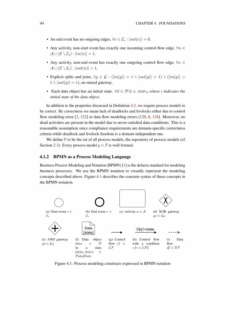
44 CHAPTER 4. FOUNDATIONS
• An end event has no outgoing edges, ∀e ∈ Ee : |out(e)| = 0,
• Any activity, non-start event has exactly one incoming control flow edge, ∀n ∈A ∪ (E \ Es) : |in(n)| = 1,
• Any activity, non-end event has exactly one outgoing control flow edge, ∀n ∈A ∪ (E \ Ee) : |out(n)| = 1,
• Explicit splits and joins, ∀g ∈ G : (|in(g)| = 1 ∧ |out(g)| > 1) ∨ (|in(g)| >1 ∧ |out(g)| = 1), no mixed gateway,
• Each data object has an initial state. ∀d ∈ D∃i ∈ stated where i indicates theinitial state of the data object,
In addition to the properties discussed in Definition 4.2, we require process models tobe correct. By correctness we mean lack of deadlocks and livelocks either due to controlflow modeling error [3, 122] or data flow modeling errors [120, 8, 134]. Moreover, nodead activities are present in the model due to never-satisfied data conditions. This is areasonable assumption since compliance requirements are domain-specific correctnesscriteria while deadlock and livelock freedom is a domain-independent one.
We define P to be the set of all process models, the repository of process models (cf.Section 2.3). Every process model p ∈ P is well formed.
4.1.2 BPMN as a Process Modeling Language
Business Process Modeling and Notation (BPMN) [1] is the defacto standard for modelingbusiness processes. We use the BPMN notation to visually represent the modelingconcepts described above. Figure 4.1 describes the concrete syntax of these concepts inthe BPMN notation.
(a) Start event s ∈Es
(b) End event e ∈Ee
(c) Activity a ∈ A (d) XOR gatewaygx ∈ GX
(e) AND gatewayga ∈ GA
(f) Data objectdata ∈ Din a state(data, state) ∈DataState
(g) Controlflow cf ∈CF
(h) Control flowwith a conditioncfc ∈ CFC
(i) Dataflowdf ∈ DF
Figure 4.1: Process modeling constructs expressed in BPMN notation
4.1. BUSINESS PROCESS MODELING 45
4.1.3 Execution Semantics
In order verify properties of the process behavior, formal execution semantics mustbe assigned to the different modeling concepts of a process model. In literature, Petrinets [113] have been widely used to formalize execution semantics of control flow aspectsof different process modeling languages [143, 137, 31], to name just a few . Moreover,there are approaches to formalize data access semantics in process models [120, 133, 8].
In this thesis, we use the formalization of control flow introduced in [31]. Also, weuse the data access semantics we developed in [8]. The advantage is that both approachesuse place/transitions Petri nets as the formal background.
Definition 4.3 (Petri net). A Petri net is a tuple PN = [P, T, F,m0] where P and T
are finite disjoint sets of places and non-empty set of transitions, respectively, F ⊆(P × T ) ∪ (T × P ) is a flow relation, and m0 : P → N is an initial marking.
For a node x ∈ P ∪ T , we define •x = y | (y, x) ∈ F and x• = y | (x, y) ∈ F.A transition t is enabled by a marking m (denoted m
t−→) if m(p) > 0 for all p ∈ •t.An enabled transition can fire in m (denoted m
t−→ m′), resulting in a successor markingm′ with m′(p) = m(p) + 1 for p ∈ t• \ •t, m′(p) = m(p) + 1 for p ∈ •t \ t•, andm′(p) = m(p) otherwise. Moreover, we define a function TID : T → N that assignseach transition an identifying number. This function plays an important role for themapping of process models to Petri nets.
4.1.3.1 Control Flow Formalization
In this section we describe the mapping [31] of the business process control flow toplace/transition Petri nets [113]. According to Definition 4.1 and Definition 4.2, we canhave the following mapping patterns as shown in Figure 4.2.
Each event or activity is mapped to a single transition t and two places pi, po wherepi ∈ •t and po ∈ t•. The difference is that the input place for the start event transition hasno incoming edges, denoted by the solid border of the place. Similarly, the output placeof the end event transition has no outgoing edges. Other types of events and activities canshare their input/output places with other preceding/succeeding nodes respectively.
An AND split gateway is mapped to a transition t, an input place pi and a set of outputplaces po1, po2, . . . , pon according to the number of outgoing edges of the split. Bothinput/output places are shared with preceding/succeeding nodes respectively. On the otherhand, an AND join is mapped to a transition t, a set of input places pi1, pi2, . . . pin anda single output place po.
An XOR split is mapped to a shared place ps, a set of transitions t1, t2, . . . , tnaccording to the number of outgoing edges of the XOR split and a set of placespo1, po2, . . . , pon also according to the number of outgoing edges of XOR split. Theplace ps is shared among the set of transitions. Place poi is the output place of transitionti. An XOR join is mapped to a shared place pj , a set of transitions t1, t2, . . . , tn and a
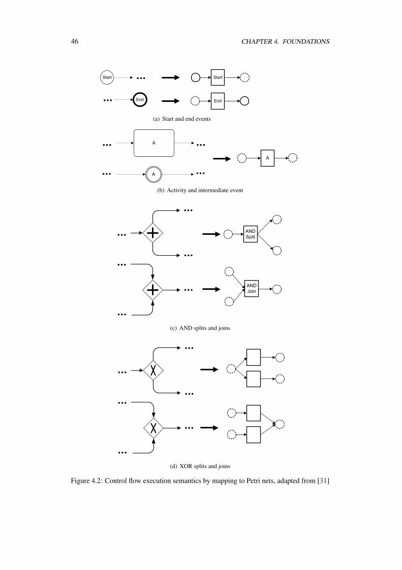
46 CHAPTER 4. FOUNDATIONS
(a) Start and end events
(b) Activity and intermediate event
(c) AND splits and joins
(d) XOR splits and joins
Figure 4.2: Control flow execution semantics by mapping to Petri nets, adapted from [31]
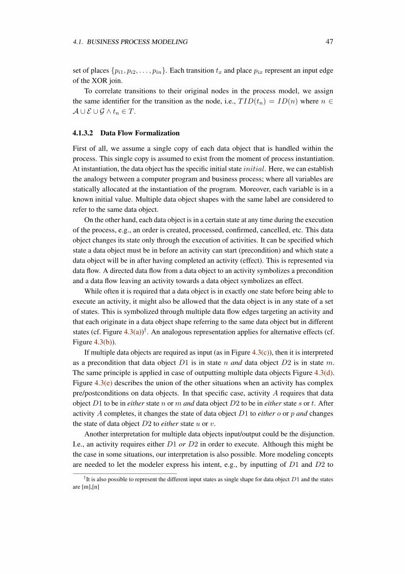
4.1. BUSINESS PROCESS MODELING 47
set of places pi1, pi2, . . . , pin. Each transition tx and place pix represent an input edgeof the XOR join.
To correlate transitions to their original nodes in the process model, we assignthe same identifier for the transition as the node, i.e., TID(tn) = ID(n) where n ∈A ∪ E ∪ G ∧ tn ∈ T .
4.1.3.2 Data Flow Formalization
First of all, we assume a single copy of each data object that is handled within theprocess. This single copy is assumed to exist from the moment of process instantiation.At instantiation, the data object has the specific initial state initial. Here, we can establishthe analogy between a computer program and business process; where all variables arestatically allocated at the instantiation of the program. Moreover, each variable is in aknown initial value. Multiple data object shapes with the same label are considered torefer to the same data object.
On the other hand, each data object is in a certain state at any time during the executionof the process, e.g., an order is created, processed, confirmed, cancelled, etc. This dataobject changes its state only through the execution of activities. It can be specified whichstate a data object must be in before an activity can start (precondition) and which state adata object will be in after having completed an activity (effect). This is represented viadata flow. A directed data flow from a data object to an activity symbolizes a preconditionand a data flow leaving an activity towards a data object symbolizes an effect.
While often it is required that a data object is in exactly one state before being able toexecute an activity, it might also be allowed that the data object is in any state of a setof states. This is symbolized through multiple data flow edges targeting an activity andthat each originate in a data object shape referring to the same data object but in differentstates (cf. Figure 4.3(a))†. An analogous representation applies for alternative effects (cf.Figure 4.3(b)).
If multiple data objects are required as input (as in Figure 4.3(c)), then it is interpretedas a precondition that data object D1 is in state n and data object D2 is in state m.The same principle is applied in case of outputting multiple data objects Figure 4.3(d).Figure 4.3(e) describes the union of the other situations when an activity has complexpre/postconditions on data objects. In that specific case, activity A requires that dataobject D1 to be in either state n or m and data object D2 to be in either state s or t. Afteractivity A completes, it changes the state of data object D1 to either o or p and changesthe state of data object D2 to either state u or v.
Another interpretation for multiple data objects input/output could be the disjunction.I.e., an activity requires either D1 or D2 in order to execute. Although this might bethe case in some situations, our interpretation is also possible. More modeling conceptsare needed to let the modeler express his intent, e.g., by inputting of D1 and D2 to
†It is also possible to represent the different input states as single shape for data object D1 and the statesare [m],[n]
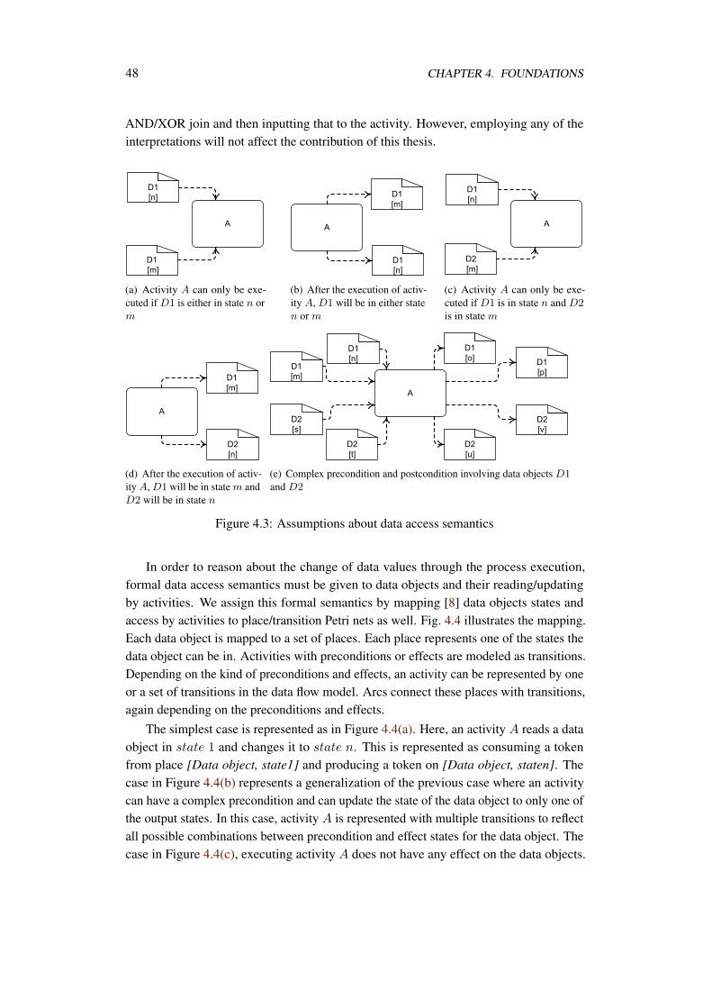
48 CHAPTER 4. FOUNDATIONS
AND/XOR join and then inputting that to the activity. However, employing any of theinterpretations will not affect the contribution of this thesis.
(a) Activity A can only be exe-cuted if D1 is either in state n orm
(b) After the execution of activ-ity A, D1 will be in either staten or m
(c) Activity A can only be exe-cuted if D1 is in state n and D2is in state m
(d) After the execution of activ-ity A, D1 will be in state m andD2 will be in state n
(e) Complex precondition and postcondition involving data objects D1and D2
Figure 4.3: Assumptions about data access semantics
In order to reason about the change of data values through the process execution,formal data access semantics must be given to data objects and their reading/updatingby activities. We assign this formal semantics by mapping [8] data objects states andaccess by activities to place/transition Petri nets as well. Fig. 4.4 illustrates the mapping.Each data object is mapped to a set of places. Each place represents one of the states thedata object can be in. Activities with preconditions or effects are modeled as transitions.Depending on the kind of preconditions and effects, an activity can be represented by oneor a set of transitions in the data flow model. Arcs connect these places with transitions,again depending on the preconditions and effects.
The simplest case is represented as in Figure 4.4(a). Here, an activity A reads a dataobject in state 1 and changes it to state n. This is represented as consuming a tokenfrom place [Data object, state1] and producing a token on [Data object, staten]. Thecase in Figure 4.4(b) represents a generalization of the previous case where an activitycan have a complex precondition and can update the state of the data object to only one ofthe output states. In this case, activity A is represented with multiple transitions to reflectall possible combinations between precondition and effect states for the data object. Thecase in Figure 4.4(c), executing activity A does not have any effect on the data objects.
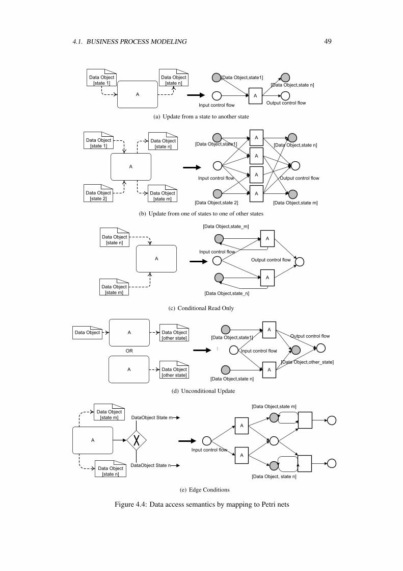
4.1. BUSINESS PROCESS MODELING 49
(a) Update from a state to another state
(b) Update from one of states to one of other states
(c) Conditional Read Only
(d) Unconditional Update
(e) Edge Conditions
Figure 4.4: Data access semantics by mapping to Petri nets
50 CHAPTER 4. FOUNDATIONS
However, it requires the data object to be in one of the specified states. This is modeledusing a bi-flow in the Petri net: The transition consumes and produces a token from thesame place. Notice that activity A might also be represented by many transitions if a dataobject is expected to be in one of many states.
The case in Figure 4.4(d) displays that the data object is changed to a certain state(other_state) when executing activity A. Multiple transitions are used as the data objectcan be in a number of previous states. For each previous state a transition models thechange to the new state. In this case, it does not make any difference if the data object isused as input (without constraint on the state) or not at all. Finally, the case in Figure 4.4(e)illustrates how data object states can also be used in branching conditions.
4.1.3.3 Formalizing Process Model to Petri Net Mapping
So far, we have shown how the control flow as well as the data flow of a well formedprocess model, see Definition 4.2, can be mapped into a place transition Petri net. How-ever, in order to reason about the behavior of the net, and so about the behavior of theprocess, we have to determine the initial marking of the net. In our case, the start event ofthe process determines the initiation of a process instance control flow. On the other hand,for data aspects, we assume that at the very beginning of the process each data object isin an initial state. Thus, the initial marking of the net is determined by putting a tokenin the input place of transition tstart corresponding to the start event. And for each dataobject initial state place a token is put.
Definition 4.4 formalizes the generation of a Petri net from a given well-formedprocess model. The formalization consolidates the different mappings provided in Fig-ures 4.2,4.4. The set of places in the resulting Petri net consists of a place for each datastate s ∈ S in the given process model. In addition, control flow places are added forstart events, control flow between nodes in the model, end events respectively.
Activities that require neither data input nor data output are represented with a singletransition each. On the other hand, those having either input or output data requirementsare represented with multiple transitions. Each of the transitions represents one of thepossible input/output conditions for the activity.
Connectivity between places and transitions comes from the control and data flowdependency between nodes in the process model. For input data dependency, each datastate place is connected as an input place for the corresponding activity transition. Thesame case for output data dependency, where transitions are connected as incomingtransitions for the corresponding output data states.
Definition 4.4. [Process model to Petri net mapping] LetP = (A, E ,D,G,S,DataState, CF ,DF , CFC, ID) be a well formed process model.
4.1. BUSINESS PROCESS MODELING 51
The Petri Net (P,T,F,m0) resulting from mapping is:
P = p(d,s)|(d, s) ∈ DataState∪ states of data objects
ps|s ∈ Es∪ start event
pe|e ∈ Ee∪ end event
p(x,y)|(x, y) ∈ CF control flow
T = ta|a ∈ (A ∪ E ∪ GA) ∧ @(_, a), (a, _)‡ ∈ DF∪
data-independent activities
t(d,s,a,s′)|a ∈ A, d ∈ D, s, s′ ∈ S ∧ s = s′ ∧ ((d, s), a), (a, (d, s′)) ∈ DF∪
activities that change data objects states
t(d,s,a)|a ∈ A, d ∈ D, s ∈ S ∧ ((d, s), a) ∈ DF ∧ @(a, (d, _)) ∈ DF∪
read only activities
t(x,y)|x ∈ GX ∧ (x, y) ∈ CF ∧ |in(x)| = 1 ∧ CFC((x, y)) = true∪
branches of XOR splits without data conditions
t(x,y,cond)|a ∈ GX ,∧(x, y) ∈ CF ∧ |in(x)| = 1 ∧ cond ∈ CFC((x, y))∪
branches of XOR splits with data conditions
t(x,y)|y ∈ GX ∧ (x, y) ∈ CF ∧ |out(x)| = 1
branches of XOR joins
F = (ps, ts)|s ∈ Es ∧ ps ∈ P ∧ ts ∈ T∪
start event
(te, pe)|e ∈ Ee ∧ pe ∈ P ∧ te ∈ T∪
end event
(tx, p(x,y))|(x, y) ∈ CF∪
control flow
(p(x,y), ty)|(x, y) ∈ CF∪
control flow
(p(d,s), t(d,s,a)), (t(d,s,a), p(d,s))|(d, s) ∈ DataState, a ∈ A,
((d, s), a) ∈ DF ,∧@(a, (d, _)) ∈ DF , p(d,s) ∈ P, t(d,s,a) ∈ T∪‡We use (a,_) to indicate that a is related to some element. Similarly is (_,a)
52 CHAPTER 4. FOUNDATIONS
read only activities
(p(d,s), t(d,s,a,s′)), (t(d,s,a,s′), p(d,s′))|(d, s), (d, s′) ∈ DataState, a ∈ A,
((d, s), a), (a, (d, s′)) ∈ DF , p(d,s), p(d,s′) ∈ P, t(d,s,a,s′) ∈ T∪
activities that update data object state
(p(d,s), t(x,y,cond)), (t(x,y,cond), p(d,s))|(d, s) ∈ cond, cond ∈ CFC((x, y)), x ∈ GX ∧|in(x)| = 1
XOR split edges conditions
The initial marking m0 is determined as ∀p ∈ P ∧ • p = ∅ m0(p) = 1
control flow initial marking
∀p ∈ P where p is an initial state data place m0(p) = 1
data flow initial marking
In this section we discussed business process modeling elements and their executionsemantics. In the next two sections, we introduce the concepts process models querylanguage BPM-Q.
4.2 BPM-Q
The Business Process Model Query (BPM-Q) language was designed to help businessprocess designers access repositories of graph-based business process models [7, 117].Thus, the language supports querying on the core concepts discussed in the previoussection. Moreover, the language introduces a set of new abstraction concepts.
A BPM-Q model is called a query. In addition to the core business process mod-eling concepts, BPM-Q introduces new concepts, as will be discussed later. A querydeclaratively describes a structural connectivity that must be satisfied by a process model.To answer a query, it is matched to the process models in the repository. The matchingdetermines the process (sub) graph that is the refinement of the query, details of matchingwill be discussed later.
BPM-Q was applied to detect modeling errors [11, 75], e.g., deadlocks. Also, it wasapplied to find semantically similar process models [10].
In this thesis, we use BPM-Q concepts to model compliance requirements. Thus,we discuss the subset of BPM-Q concepts that are useful to the compliance use case,interested readers can refer to [7, 117] for mode details.
In the following subsections we introduce a subset of the new concepts in BPM-Quseful for the compliance use case. Also, we describe the steps of matching a query to aprocess model.
4.2. BPM-Q 53
4.2.1 BPM-Q Concepts
In addition to the core concepts of process modeling, activities, events, control flow, dataflow, etc. BPM-Q has two major new concepts (constructs) that will be used for modelingcompliance requirements, the path edge and the anonymous activity. Both concepts aremeans to provide abstraction over process model details. This matches the abstract natureof compliance requirements as will be shown in Chapter 5.
• Path edges: a path edge connecting two nodes in a query represents an abstractionover whatever control nodes could be in between in the process model. Moreover,a path edge has an exclude property. When the exclude property is set to somenode(s), the evaluation of the path edge succeeds only if there are sequences ofnodes between the source and destination nodes to whom excluded node(s) do notbelong.
• Anonymous activities: Are meant to abstract from activities. For instance, a querycould be “what activities read/update the insurance claim data object?”. Since, theuser does not know that activity, he/she can start its label with the ’@’ symbol todeclare it as an anonymous activity.
4.2.2 Matching Queries to Processes
A BPM-Q query is matched to a process via a set of refinements to the query. With eachrefinement nodes/edges in a query are replaced with nodes/(nodes,edges) of the matchingprocess model. This operation is repeated until either a node/edge cannot be resolved,or all nodes/edges have been resolved. The match to the query, its final refinement, is asub-graph of the process model.
Next, we formalize the notion of a BPM-Q query and the notion of matching a queryto a process. We define a BPM-Q query as follows.
Definition 4.5. [BPM-Q query] a BPM-Q query is a tupleQ = (AQ, EQ,DQ,GQ,SQ,DataStateQ,PQ,DFQ, isAnonymous,X , IDQ) where:
• AQ is a finite set of activities in a query,
• EQ is a finite set of events in a query. EQ = EQs ∪ EQe where EQs is the set ofstart events and EQe is the set of end events in a query, EQs ∩ EQe = ∅,
• DQ is a finite set of data objects in a query,
• GQ is a finite set of control flow routing gateways. This set is further subdivided intoGQX and GQA, representing XOR and AND gateways respectively. GQX ∩ GQA =
∅,
• SQ is a finite set of states(values) data objects assume within a query,
54 CHAPTER 4. FOUNDATIONS
• DataStateQ ⊆ DQ × SQ is the data state relation in a query,
• PQ ⊆ (AQ ∪ EQ) × (AQ ∪ EQ) is the path relation between activity and eventnodes in a query,
• DFQ ⊆ (DataStateQ × AQ) ∪ (AQ × DataStateQ) is the data flow relationbetween activities and data objects with states,
• isAnonymous : AQ → true, false determines whether activities in a queryare anonymous,
• X : PQ → 2AQ∪EQ is the exclude property for path edges,
• IDQ : AQ ∪ EQ ∪ GQ → N is a function that assigns an identifier to each controlflow node in the query.
We assume the set Q to be the universal set of queries. Since BPM-Q is designedto match queries to process definitions in a repository, it is necessary to identify acandidate set of process models that might have the chance to provide a match to thequery, rather than scanning the whole repository [128]. To achieve this, we assumea common ontology TAG is used to annotate both processes [130] and queries. Thefunction annotate : P ∪Q → 2TAG assigns tags to processes and queries.
Definition 4.6. [Candidate match] a process modelP = (A, E ,D,G,S,DataState, CF ,DF , CFC, ID) is said to be relevant to a queryQ = (AQ, EQ,DQ,GQ,SQ,DataStateQ,PQ,DFQ, isAnonymous,X , IDQ)
if annotate(P) ∩ annotate(Q) = ∅. Thus, the set PQ = p ∈ P : p is relevant to Qrepresents the candidate match processes to a query.
After identifying the candidate match set of processes, the query processor continuesby doing the following steps in sequence for each of the candidate match processes. Ifany of the steps fails, the processor drops the investigated process. The steps are detailedas follows:
1. Resolving non anonymous activities.
2. Resolving data objects.
3. Resolve gateway nodes
4. Resolving events.
5. Resolving anonymous activities.
6. Substituting path edges.
4.2. BPM-Q 55
We start with an unrefined query. This is a query whose nodes are all assigned thevalue 0 as an identifier. With each of the steps above, some nodes are resolved. Resolutionis done by binding a node in the query to a node in the process model. This bindingoccurs simply by assigning the node in the query the same identifier of the node in theprocess model.
To help describe the resolution of activities and data object nodes, we assume afunction label. label is used to find activity and data object nodes in a process that canbe matched to those of a query. It is possible that an activity node in a query has morethan one match activity node in a process, in case a process has multiple occurrences ofthe same activity. For each possible resolution node np of a query node nq, the queryprocessor generates a new copy of the query where nq is assigned the same identifieras np. The new identifier of nq is propagated to all its control flow, data flow, or pathsrelations. If for any node nq in a query we cannot find a resolution np, the matching of aquery to a process is dropped. The resolution of events is simple. Each event node in thequery has to have a counterpart in the candidate process model, this is guaranteed in thecase of well formed process models cf. Definition 4.2.
Resolving anonymous activities is achieved by finding an activity in the candidateprocess model for which all relations of the anonymous activity in the query are satisfied.For instance, if some anonymous activity ‘@A’ has a data flow edge to some data object‘D’ in the query, activity ‘M’ in the candidate process model is a resolution to ‘@A’ iffthere is a data flow edge to ‘D’ in the process. In case that an anonymous activity in aquery has no data flow relationships, the query processor tries all available activities inthe process model. Each time an anonymous activity is resolved, the query processorgenerates a new copy of the query where the anonymous activity is replaced with theresolvant activity. Also, this replacement is propagated to all relations of the anonymousactivity. Gateways are resolved in the same way.
Note that our description about matching a query to a process is limited to the subsetwe use in this thesis. More details can be found in [7, 117]
As mentioned above, the query processor generates a new copy of the query when itbinds a node. A query that has a subset of its nodes bound is called a partially refinedquery. On the other hand, when all resolution steps are completed, all queries are refined,i.e., all nodes are bound. We can notice that the resolution steps are of combinatorialnature, as the query processor has to find all possible bindings to every node. However,it is possible to start the query processing by a partially or completely refined query,we will use this feature heavily in Chapter 6 when we talk about compliance violationexplanation.
Finally, for each refined query the query processor substitutes path edges in a querywith the set of nodes and edges in the process model that constitute the process sub-graphin which the target node of the edge is reachable from its source.
To help explain how path edges are substituted, we define the transitive closure overthe control flow relation.
56 CHAPTER 4. FOUNDATIONS
Definition 4.7. [Transitive closure over control flow]Let P = (A, E ,D,G,S,DataState, CF ,DF , CFC, ID) be a well-formed processmodel. The transitive closure over the control flow relation is defined as CF∗. Foreach node n ∈ A∪G ∪ E , we define the set of reachable nodes from n as [[n]]CF∗ = m :
(n,m) ∈ CF∗.
Based on the above definition, we can define the reachable nodes from some node x
under different conditions. For instance [[x]](CF\(x,y))∗ defines the reachable node fromnode x where we removed the edge (x, y) from the control flow relation CF .
With the help of Definition 4.7, we can explain how path edges are evaluated. Apath edge (source, target, EXC) evaluates to a sub-graph in which all nodes are 1)reachable from source node 2) target node is reachable from every node 3) every nodee ∈ EXC is not in the sub-graph and every node solely reachable by e is not in thesub-graph either 4) edges between nodes in the sub-graph are those between these nodesin the process model.
Definition 4.8. [Subgraph] Let N = A ∪ E ∪ G be the set of control flow nodes in aprocess model P = (A, E ,D,G,S,DataState, CF ,DF , CFC, ID). Let EXC be theset of nodes to be excluded from a path evaluation. Let CFEXC = CF \ (x, y) : y ∈EXC ∧ (x, y) ∈ CF be the control flow relation without edges incoming to excludednodes. A function subgraph (a, b, EXC) := (N ′, E′), where a, b ∈ N , and EXC is theset of nodes to be excluded, constructs the process sub-graph where:
• N ′ = n : n ∈ [[a]]CF∗EXC
∧ b ∈ [[n]]CF∗EXC
,
• E′ = (x, y) : x, y ∈ N ′ ∧ (x, y) ∈ CF.
If N ′ = ∅, the subgraph is empty.
A candidate process model is said to match the refined query if it satisfies all pathedges and data flow dependencies as in Definition 4.9.
Definition 4.9. [Matching a query to a business process model]A candidate process model P = (A, E ,D,G,S,DataState, CF ,DF , CFC, ID)
matches a queryQ = (AQ, EQ,DQ,GQ,SQ,DataStateQ,PQ,DFQ, isAnonymous,X , IDQ) if :
• ∀aq ∈ AQ ∧ isAnonymous(a) = false ∃ap ∈ A : label(aq) = label(ap). Eachnon-anonymous activity must have at least one activity in the process model withthe same label,
• ∀e ∈ EQ∃e′ ∈ E where e′ is a resolvant for e. Each event in the query must have acounterpart event in the process,
• ∀dq ∈ DQ∃dp ∈ D : label(dq) = label(dp). Each data object in the query musthave a data object in the process with the same label,
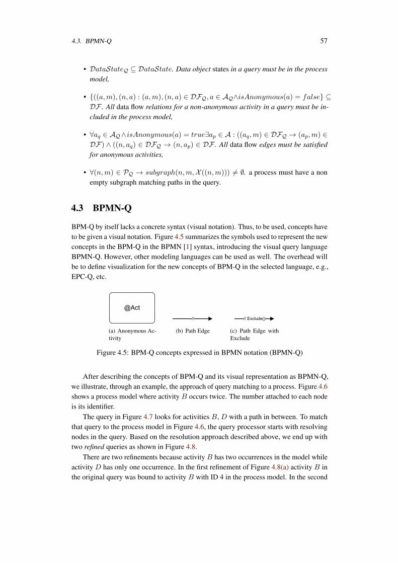
4.3. BPMN-Q 57
• DataStateQ ⊆ DataState. Data object states in a query must be in the processmodel,
• ((a,m), (n, a) : (a,m), (n, a) ∈ DFQ, a ∈ AQ∧isAnonymous(a) = false ⊆DF . All data flow relations for a non-anonymous activity in a query must be in-cluded in the process model,
• ∀aq ∈ AQ∧ isAnonymous(a) = true∃ap ∈ A : ((aq,m) ∈ DFQ → (ap,m) ∈DF) ∧ ((n, aq) ∈ DFQ → (n, ap) ∈ DF . All data flow edges must be satisfiedfor anonymous activities,
• ∀(n,m) ∈ PQ → subgraph(n,m,X ((n,m))) = ∅. a process must have a nonempty subgraph matching paths in the query.
4.3 BPMN-Q
BPM-Q by itself lacks a concrete syntax (visual notation). Thus, to be used, concepts haveto be given a visual notation. Figure 4.5 summarizes the symbols used to represent the newconcepts in the BPM-Q in the BPMN [1] syntax, introducing the visual query languageBPMN-Q. However, other modeling languages can be used as well. The overhead willbe to define visualization for the new concepts of BPM-Q in the selected language, e.g.,EPC-Q, etc.
(a) Anonymous Ac-tivity
(b) Path Edge (c) Path Edge withExclude
Figure 4.5: BPM-Q concepts expressed in BPMN notation (BPMN-Q)
After describing the concepts of BPM-Q and its visual representation as BPMN-Q,we illustrate, through an example, the approach of query matching to a process. Figure 4.6shows a process model where activity B occurs twice. The number attached to each nodeis its identifier.
The query in Figure 4.7 looks for activities B, D with a path in between. To matchthat query to the process model in Figure 4.6, the query processor starts with resolvingnodes in the query. Based on the resolution approach described above, we end up withtwo refined queries as shown in Figure 4.8.
There are two refinements because activity B has two occurrences in the model whileactivity D has only one occurrence. In the first refinement of Figure 4.8(a) activity B inthe original query was bound to activity B with ID 4 in the process model. In the second
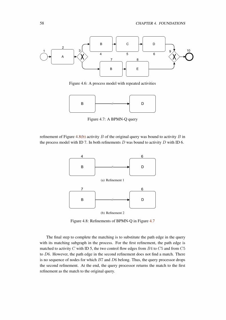
58 CHAPTER 4. FOUNDATIONS
Figure 4.6: A process model with repeated activities
Figure 4.7: A BPMN-Q query
refinement of Figure 4.8(b) activity B of the original query was bound to activity B inthe process model with ID 7. In both refinements D was bound to activity D with ID 6.
(a) Refinement 1
(b) Refinement 2
Figure 4.8: Refinements of BPMN-Q in Figure 4.7
The final step to complete the matching is to substitute the path edge in the querywith its matching subgraph in the process. For the first refinement, the path edge ismatched to activity C with ID 5, the two control flow edges from B4 to C5 and from C5
to D6. However, the path edge in the second refinement does not find a match. Thereis no sequence of nodes for which B7 and D6 belong. Thus, the query processor dropsthe second refinement. At the end, the query processor returns the match to the firstrefinement as the match to the original query.
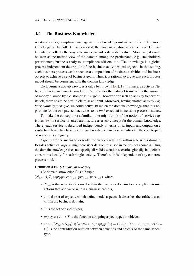
4.4. THE BUSINESS KNOWLEDGE 59
4.4 The Business Knowledge
As stated earlier, compliance management is a knowledge-intensive problem. The moreknowledge can be collected and encoded; the more automation we can achieve. Domainknowledge reflects the way a business provides its added value. Moreover, it couldbe seen as the unified view of the domain among the participants, e.g., stakeholders,practitioners, business analysts, compliance officers, etc. The knowledge is a globalprocess-independent description of the business activities and objects. In this setting,each business process can be seen as a composition of business activities and businessobjects to achieve a set of business goals. Thus, it is rational to argue that each processmodel should be consistent with the domain knowledge.
Each business activity provides a value by its own [151]. For instance, an activity Payback claim to customer by bank transfer provides the value of transferring the amountof money claimed by a customer as its effect. However, for such an activity to performits job, there has to be a valid claim as an input. Moreover, having another activity Payback claim by a cheque, we could derive, based on the domain knowledge, that it is notpossible for the two payment activities to be both executed in the same process instance.
To make the concept more familiar, one might think of the notion of service reg-istries [98] in service oriented architecture as a sub-concept for the domain knowledge.There, each service is described independently in terms of its inputs and outputs on asyntactical level. In a business domain knowledge, business activities are the counterpartof services in a registry.
Aspects are the means to describe the various relations within a business domain.Besides activities, aspects might consider data objects used in the business domain. Thus,the domain knowledge does not specify all valid execution scenarios globally, but definesconstraints locally for each single activity. Therefore, it is independent of any concreteprocess model.
Definition 4.10. [Domain knowledge]The domain knowledge C is a 7-tuple
(Nact, A, T, asptype, cont∈T , pret∈T , postt∈T ), where:
• Nact is the set activities used within the business domain to accomplish atomicactions that add value within a business process,
• A is the set of objects, which define model aspects. It describes the artifacts usedwithin the business domain,
• T is the set of aspect types,
• asptype : A → T is the function assigning aspect types to objects,
• cont : (Nact×Nact)∪(a : ∀a ∈ A, asptype(a) = t×a : ∀a ∈ A, asptype(a) =
t) is the contradiction relation between activities and objects of the same aspecttype.
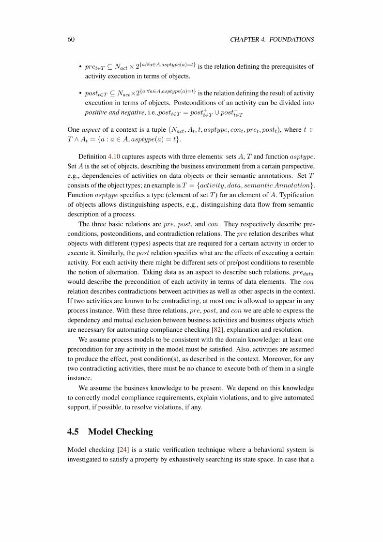
60 CHAPTER 4. FOUNDATIONS
• pret∈T ⊆ Nact × 2a:∀a∈A,asptype(a)=t is the relation defining the prerequisites ofactivity execution in terms of objects.
• postt∈T ⊆ Nact×2a:∀a∈A,asptype(a)=t is the relation defining the result of activityexecution in terms of objects. Postconditions of an activity can be divided intopositive and negative, i.e.,postt∈T = post+t∈T ∪ post−t∈T
One aspect of a context is a tuple (Nact, At, t, asptype, cont, pret, postt), where t ∈T ∧At = a : a ∈ A, asptype(a) = t.
Definition 4.10 captures aspects with three elements: sets A, T and function asptype.Set A is the set of objects, describing the business environment from a certain perspective,e.g., dependencies of activities on data objects or their semantic annotations. Set Tconsists of the object types; an example is T = activity, data, semantic Annotation.Function asptype specifies a type (element of set T ) for an element of A. Typificationof objects allows distinguishing aspects, e.g., distinguishing data flow from semanticdescription of a process.
The three basic relations are pre, post, and con. They respectively describe pre-conditions, postconditions, and contradiction relations. The pre relation describes whatobjects with different (types) aspects that are required for a certain activity in order toexecute it. Similarly, the post relation specifies what are the effects of executing a certainactivity. For each activity there might be different sets of pre/post conditions to resemblethe notion of alternation. Taking data as an aspect to describe such relations, predatawould describe the precondition of each activity in terms of data elements. The con
relation describes contradictions between activities as well as other aspects in the context.If two activities are known to be contradicting, at most one is allowed to appear in anyprocess instance. With these three relations, pre, post, and con we are able to express thedependency and mutual exclusion between business activities and business objects whichare necessary for automating compliance checking [82], explanation and resolution.
We assume process models to be consistent with the domain knowledge: at least oneprecondition for any activity in the model must be satisfied. Also, activities are assumedto produce the effect, post condition(s), as described in the context. Moreover, for anytwo contradicting activities, there must be no chance to execute both of them in a singleinstance.
We assume the business knowledge to be present. We depend on this knowledgeto correctly model compliance requirements, explain violations, and to give automatedsupport, if possible, to resolve violations, if any.
4.5 Model Checking
Model checking [24] is a static verification technique where a behavioral system isinvestigated to satisfy a property by exhaustively searching its state space. In case that a
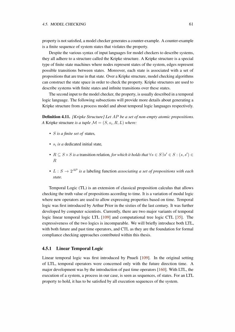
4.5. MODEL CHECKING 61
property is not satisfied, a model checker generates a counter-example. A counter-exampleis a finite sequence of system states that violates the property.
Despite the various syntax of input languages for model checkers to describe systems,they all adhere to a structure called the Kripke structure. A Kripke structure is a specialtype of finite state machines where nodes represent states of the system, edges representpossible transitions between states. Moreover, each state is associated with a set ofpropositions that are true in that state. Over a Kripke structure, model checking algorithmscan construct the state space in order to check the property. Kripke structures are used todescribe systems with finite states and infinite transitions over these states.
The second input to the model checker, the property, is usually described in a temporallogic language. The following subsections will provide more details about generating aKripke structure from a process model and about temporal logic languages respectively.
Definition 4.11. [Kripke Structure] Let AP be a set of non-empty atomic propositions.A Kripke structure is a tuple M = (S, si, R, L) where:
• S is a finite set of states,
• si is a dedicated initial state,
• R ⊆ S×S is a transition relation, for which it holds that ∀s ∈ S∃s′ ∈ S : (s, s′) ∈R
• L : S → 2AP is a labeling function associating a set of propositions with eachstate.
Temporal Logic (TL) is an extension of classical proposition calculus that allowschecking the truth value of propositions according to time. It is a variation of modal logicwhere new operators are used to allow expressing properties based on time. Temporallogic was first introduced by Arthur Prior in the sixties of the last century. It was furtherdeveloped by computer scientists. Currently, there are two major variants of temporallogic linear temporal logic LTL [109] and computational tree logic CTL [35]. Theexpressiveness of the two logics is incomparable. We will briefly introduce both LTL,with both future and past time operators, and CTL as they are the foundation for formalcompliance checking approaches contributed within this thesis.
4.5.1 Linear Temporal Logic
Linear temporal logic was first introduced by Pnueli [109]. In the original settingof LTL, temporal operators were concerned only with the future direction time. Amajor development was by the introduction of past time operators [160]. With LTL, theexecution of a system, a process in our case, is seen as sequences, of states. For an LTLproperty to hold, it has to be satisfied by all execution sequences of the system.
62 CHAPTER 4. FOUNDATIONS
Assuming a set of atomic propositions AP that describe facts about behavior of asystem, LTL defines a set of temporal operators in addition to classical logical operators(¬,∨,∧,→)
Definition 4.12. [LTL Syntax] Let AP be a set of atomic propositions. LTL for-mulas can be defined according to the grammar θ ::= ⊤|⊥|p|¬θ|θ ∧ θ|θ ∨ θ|θ →θ|Fθ|Gθ|θUθ|Oθ|θSθ, where p ∈ AP .
These operators are used to describe the truth value of propositions describing thebehavior of a system over time. So, an execution of the system M = (S, si, R, L)
can be seen as a trace, a sequence of states, σ = s0, s1, . . . where each state si, i > 0,is associated with a set of propositions L(si) that are true in that state. We say thatproposition p ∈ P is true at state si by si |= p.
Informally, the semantics of the different temporal operators are defined as follows
• F(θ): in some future state of the system θ will hold.
• G(θ): θ hold in the current state and in every future state.
• ωUθ: ω is true in all states until the point (state) θ becomes true. There has to be astate where θ becomes true.
• O(θ): O is the history-looking counterpart of the F operator. That is, at the stateevaluating O(θ), there must have been some previous state where θ was true.
• ωSθ: similarly, S is the history-looking counter part of the U operator. That is, atthe state evaluating ωSθ, ω was true since the state where θ was true.
Definition 4.13 formally describes the semantics of the LTL operators.
Definition 4.13. [LTL Semantics] Let σ = s0, s1, . . . be a word in Σ∗ with Σ = 2P . Letθ be an LTL formula. Given a trace σ and a position i The relation σ.i |= θ is defined as:
• σ.i |= ⊤ for any i,
• σ.i |= ⊥ for any i,
• σ.i |= p if p ∈ L(si),
• σ.i |= ¬θ1 if σ.i |= θ1,
• σ.i |= θ1 ∧ θ2 if σ.i |= θ1 and σ.i |= θ2,
• σ.i |= θ1 ∨ θ2 if σ.i |= θ1 or σ.i |= θ2,
• σ.i |= θ1 → θ2 if σ.i |= θ1 or σ.i |= θ2,
• σ.i |= Fθ if ∃k ≥ i : σ.k |= θ,
4.5. MODEL CHECKING 63
• σ.i |= Gθ if ∀k ≥ i : σ.k |= θ,
• σ.i |= θ1Uθ2 if ∃k ≥ i : σ.k |= θ2 and ∀j, i ≤ j < k, : σ.j |= θ1,
• σ.i |= Oθ if i ≥ 1,∃k < i : σ.k |= θ,
• σ.i |= Hθ if i ≥ 1,∀0 ≤ k ≤ i : σ.k |= θ,
• σ.i |= θ1Sθ2 if ∃k ≤ i, σ.k |= θ2 and ∀k < j ≤ i, σ.j |= θ1.
If the behavior of a system M is nondeterministic, a set of sequences Ω representsthe different possibilities of execution. For a system M to satisfy an LTL formula θ,written as M |= θ, all sequences of M have to satisfy θ.
Definition 4.14. [LTL property satisfaction] Let Ω be the set of traces of a system M.M is said to satisfy an LTL formula θ, M |= θ if ∀σ ∈ Ω∃i : σ.i |= θ.
4.5.2 Computational Tree Logic
Computational tree logic (CTL) is another language to express properties for modelchecking. Unlike LTL, CTL is designed to handle nondeterminism in the behavior of asystem M. Thus, in addition to introducing temporal operators; it also introduces globaland existential quantifiers.
Definition 4.15. [CTL Syntax] Let AP be a set of atomic propositions. CTL formulas canbe defined according to the grammar θ ::= ⊤|⊥|p|¬θ|θ∧θ|θ∨θ|θ → θ|AFθ|EFθ|AGθ
|EGθ|A[θUθ]|E[θUθ], where p ∈ AP .
With respect to a system M = (S, si, R, L), for each state s ∈ S, there could bemore than one subsequent state. Recursively, for each subsequent state there could bemore than one subsequent state, etc. Thus, starting at any state s ∈ S we could havemultiple paths to go. CTL gives the possibility to express temporal formulas over all ofthese paths or some of these paths.
Definition 4.16. [CTL Semantics] Let M = (S, si, R, L) be a transitions system. Let θbe a CTL formula and s ∈ S. M, s |= θ is defined as:
• M, s |= ⊤,
• M, s |= ⊥,
• M, s |= p if p ∈ L(s),
• M, s |= ¬θ if M, s |= θ,
• M, s |= θ1 ∧ θ2 if M, s |= θ1 and M, s |= θ2,
• M, s |= θ1 ∨ θ2 if M, s |= θ1 or M, s |= θ2,
64 CHAPTER 4. FOUNDATIONS
• M, s |= θ1 → θ2 if M, s |= θ1 or M, s |= θ2,
• M, s |= AFθ if ∀ path p = s, s2, s3, . . . there is a state sj such that M, sj |= θ,
• M, s |= EFθ if ∃ path p = s, s2, s3, . . . there is a state sj such that M, sj |= θ,
• M, s |= AGθ if ∀ path p = s, s2, s3, . . . for each state sj on each p M, sj |= θ,
• M, s |= EGθ if ∃ path p = s, s2, s3, . . . and for each state sj on that pathM, sj |= θ,
• M, s |= A[θ1Uθ2] if ∀ path p = s, s2, s3, . . . there is a state sj such that M, sj |=θ2 and ∀i < j,M, si |= θ1,
• M, s |= E[θ1Uθ2] if ∃ path p = s, s2, s3, . . . there is a state sj such that M, sj |=θ2 and ∀i < j,M, si |= θ1
CTL and LTL expressiveness is incomparable [146]. However, there is a commonset of specifications that can be expressed in both LTL and CTL [85]. For this commonspace, CTL and LTL model checkers practically perform similarly [18].
While both LTL and CTL are capable of formalizing compliance requirements, aswill be discussed in Chapter 5, CTL can formalize violations scenarios, as will be shownin Chapter 6, due to the ability to express existential formulas.
There are well-known logical equivalences in CTL§. We list some of them useful forthe work presented in this thesis.
AGθ ≡ ¬EF(¬θ) (4.1)
AFθ ≡ ¬EG(¬θ) (4.2)
A[θ UΨ] ≡ ¬(F[(¬Ψ)U ¬(θ ∨Ψ)] ∨EG(¬Ψ)) (4.3)
4.5.3 Temporal Logic Querying
Usually, model checking is an iterative process where the modeler gains more under-standing of the system each time a property is violated. To enhance the understandingof system behavior and to gain more feedback, Chan [21] proposed to develop temporallogic queries (TLQ). In temporal logic queries, user puts a placeholder ?; the querysolver has to find the strongest propositional formula p, formula composed of atomicpropositions and classical logical connectors, that replaces the placeholder and makethe resulting formula true. For instance, the query AG(?) simply asks about the modelinvariants. This mechanizes and speeds up the trial and error effort of analyzing a de-sign [20]. To help the user focus more on specific properties, temporal logic queries
§These equivalences can be proved by contradiction in a straightforward manner
4.5. MODEL CHECKING 65
can be restricted(projected) on a specific set of propositions. For instance AG(?x,y) isrestricted version of the previous query where result is a propositional formula basedon x, y only. Model checking is a subproblem of temporal logic querying. In modelchecking, we ask only Boolean queries.
Temporal logic queries are also of great value to explain violations. Consider a CTLformula AG(x ∧ y → AF(z)) that is checked against some system M = (S, si, R, L).In case of violation, model checkers generate counter examples. However, counterexamples are not always useful. It simply finds a sequence of states that causes theviolation. In our case, there is some state sj ∈ S where x, y ∈ L(sj) and there is nofurther state sk reachable from sj where z ∈ L(sk). Suppose that the user issues thefollowing temporal logic query AG(? → AF(z)). The solver returns x ∧ y ∧ r as avalue for ?. In this case, the user got more useful feedback and learned more about themodel.
Definition 4.17. [Temporal Logic Query Checking] Let AP be a set of non-empty atomicpropositions and AP ′ ⊂ AP . Let PF be the set of propositional formulas the canbe made from atomic propositions in AP . Let M be a Kripke structure and let φ bea temporal logic query, both are defined over AP . The query checking problem is tocompute the set ϵ ∈ PF (AP ′)|M |= φ[ϵ].
Definition 4.17 formally describes the problem of temporal logic query checking.The set AP ′ represents the atomic propositions relevant to the query. Thus, the querysolver (checkers) finds the set of strongest propositional formulas ϵ that would make theKripke structure M satisfy the temporal logic formula φ[ϵ] obtained by substituting ϵ forthe place holder in the query φ.
Generally, the temporal logic query solving can be reduced to several model checkingproblems [21, 20]. The worst case complexity for a TLQ solver is to model check 22
|AP ′|
formulas with length at most |φ|+O(2|AP ′|). However, there were research on developingmore efficient solvers [22].
In Chapter 6, we employ temporal logic querying techniques to help explain andprovide useful feedback to the user. As will be discussed, when data related compliancerules are violated; temporal logic queries are issued to extract specific data conditionsthat caused the violation. Thus, the user focuses on parts of the process model that needsconsideration. Also, we show how domain-specific knowledge can be used to simplifysolving temporal queries to linear time model checking rather than its doubly exponentialnature.

Chapter 5
Modeling and CheckingCompliance Rules
The core objective of this thesis is to support automated checking of compliance rulesagainst business process models at design-time. In this situation, control flow and dataflow aspects are feasible to check. In many cases, it is necessary to ensure that certainactivities exist in the process model. Also, execution ordering between activities must beverified. Moreover, execution ordering might be required to hold only under certain dataconditions. Thus, the control flow, the data flow and the interplay between them need tobe expressed in compliance rules.
Model checking [24] provides a formal approach for static verification with acceptableperformance [154, 34]. However, an obstacle for directly employing the model checkingapproach is that the specification language for rules, i.e., temporal logic, is too technicalto be used by business people. Moreover, it gives a very wide range of rules to bespecified. However, certain patterns of rules might be sufficient to express compliancerequirements [33, 39, 94].
To overcome this obstacle, we provide the users with a simple visual language toexpress compliance rules, BPMN-Q. As was discussed in Section 4.3, BPMN-Q is avisual language to query the structure of process models. It uses notations very similar tothat used for designing process models. Also, BPMN-Q provides means for abstractionover process models details, e.g., path edges and anonymous activities. This matches theabstract and declarative nature of compliance rules, cf. Req. 1.
We follow a pattern-based approach to express compliance rules [42, 33]. Eachpattern is expressed visually in BPMN-Q. Thus, it helps the user specify rules withoutdealing with complexity of formal languages [9, 16, 14]. On the other hand, each patternis mapped into a formula in temporal logic, enabling automated verification. Patternsare mapped into computation tree logic CTL [35] and past time linear temporal logicPLTL [160]. The purpose of providing these various mappings is to ensure independence
67
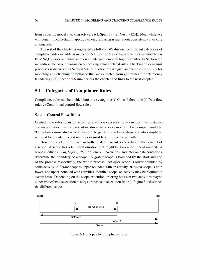
68 CHAPTER 5. MODELING AND CHECKING COMPLIANCE RULES
from a specific model checking software (cf. Spin [59] vs. Nusmv [23]). Meanwhile, wewill benefit from certain mappings when discussing issues about consistency checkingamong rules.
The rest of the chapter is organized as follows. We discuss the different categories ofcompliance rules we address in Section 5.1. Section 5.2 explains how rules are modeled asBPMN-Q queries and what are their counterpart temporal logic formulas. In Section 5.3we address the issue of consistency checking among related rules. Checking rules againstprocesses is discussed in Section 5.4. In Section 5.5 we give an example case study formodeling and checking compliance that we extracted from guidelines for anti moneylaundering [25]. Section 5.6 summarizes the chapter and links to the next chapter.
5.1 Categories of Compliance Rules
Compliance rules can be divided into three categories a) Control flow rules b) Data flowrules c) Conditional control flow rules.
5.1.1 Control Flow Rules
Control flow rules focus on activities and their execution relationships. For instance,certain activities must be present or absent in process models. An example would be“Complaints must always be archived”. Regarding to relationships, activities might berequired to execute in a certain order or must be exclusive to each other.
Based on work in [33], we can further categorize rules according to the concept ofa scope. A scope has a temporal duration that might be lower- or upper-bounded. Ascope is either global, before, after, or between. Activities, and later on data conditions,determine the boundary of a scope. A global-scope is bounded by the start and endof the process respectively, the whole process. An after-scope is lower-bounded bysome activity. A before-scope is upper-bounded with an activity. Between-scope is bothlower- and upper-bounded with activities. Within a scope, an activity may be required toexist/absent. Depending on the scope execution ordering between two activities maybeeither precedence (execution history) or response (execution future). Figure 5.1 describesthe different scopes.
Figure 5.1: Scopes for compliance rules
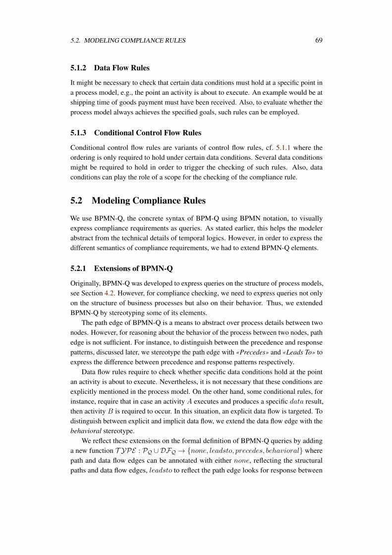
5.2. MODELING COMPLIANCE RULES 69
5.1.2 Data Flow Rules
It might be necessary to check that certain data conditions must hold at a specific point ina process model, e.g., the point an activity is about to execute. An example would be atshipping time of goods payment must have been received. Also, to evaluate whether theprocess model always achieves the specified goals, such rules can be employed.
5.1.3 Conditional Control Flow Rules
Conditional control flow rules are variants of control flow rules, cf. 5.1.1 where theordering is only required to hold under certain data conditions. Several data conditionsmight be required to hold in order to trigger the checking of such rules. Also, dataconditions can play the role of a scope for the checking of the compliance rule.
5.2 Modeling Compliance Rules
We use BPMN-Q, the concrete syntax of BPM-Q using BPMN notation, to visuallyexpress compliance requirements as queries. As stated earlier, this helps the modelerabstract from the technical details of temporal logics. However, in order to express thedifferent semantics of compliance requirements, we had to extend BPMN-Q elements.
5.2.1 Extensions of BPMN-Q
Originally, BPMN-Q was developed to express queries on the structure of process models,see Section 4.2. However, for compliance checking, we need to express queries not onlyon the structure of business processes but also on their behavior. Thus, we extendedBPMN-Q by stereotyping some of its elements.
The path edge of BPMN-Q is a means to abstract over process details between twonodes. However, for reasoning about the behavior of the process between two nodes, pathedge is not sufficient. For instance, to distinguish between the precedence and responsepatterns, discussed later, we stereotype the path edge with «Precedes» and «Leads To» toexpress the difference between precedence and response patterns respectively.
Data flow rules require to check whether specific data conditions hold at the pointan activity is about to execute. Nevertheless, it is not necessary that these conditions areexplicitly mentioned in the process model. On the other hand, some conditional rules, forinstance, require that in case an activity A executes and produces a specific data result,then activity B is required to occur. In this situation, an explicit data flow is targeted. Todistinguish between explicit and implicit data flow, we extend the data flow edge with thebehavioral stereotype.
We reflect these extensions on the formal definition of BPMN-Q queries by addinga new function T YPE : PQ ∪ DFQ → none, leadsto, precedes, behavioral wherepath and data flow edges can be annotated with either none, reflecting the structuralpaths and data flow edges, leadsto to reflect the path edge looks for response between
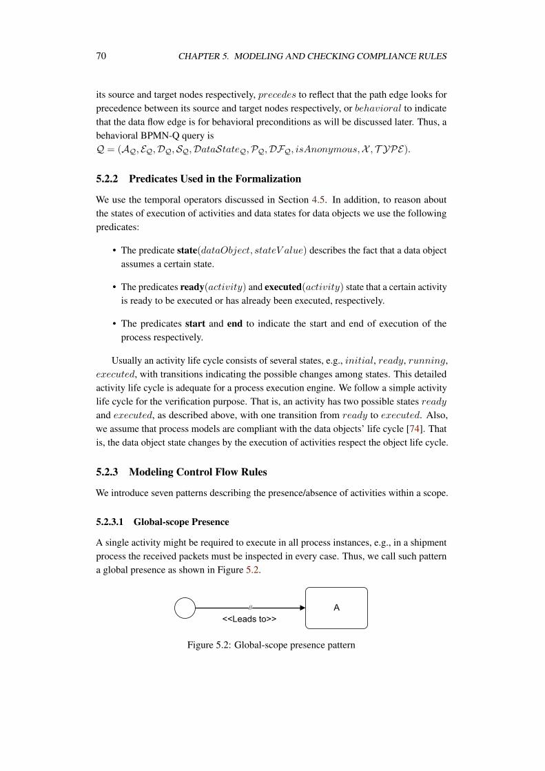
70 CHAPTER 5. MODELING AND CHECKING COMPLIANCE RULES
its source and target nodes respectively, precedes to reflect that the path edge looks forprecedence between its source and target nodes respectively, or behavioral to indicatethat the data flow edge is for behavioral preconditions as will be discussed later. Thus, abehavioral BPMN-Q query isQ = (AQ, EQ,DQ,SQ,DataStateQ,PQ,DFQ, isAnonymous,X , T YPE).
5.2.2 Predicates Used in the Formalization
We use the temporal operators discussed in Section 4.5. In addition, to reason aboutthe states of execution of activities and data states for data objects we use the followingpredicates:
• The predicate state(dataObject, stateV alue) describes the fact that a data objectassumes a certain state.
• The predicates ready(activity) and executed(activity) state that a certain activityis ready to be executed or has already been executed, respectively.
• The predicates start and end to indicate the start and end of execution of theprocess respectively.
Usually an activity life cycle consists of several states, e.g., initial, ready, running,executed, with transitions indicating the possible changes among states. This detailedactivity life cycle is adequate for a process execution engine. We follow a simple activitylife cycle for the verification purpose. That is, an activity has two possible states readyand executed, as described above, with one transition from ready to executed. Also,we assume that process models are compliant with the data objects’ life cycle [74]. Thatis, the data object state changes by the execution of activities respect the object life cycle.
5.2.3 Modeling Control Flow Rules
We introduce seven patterns describing the presence/absence of activities within a scope.
5.2.3.1 Global-scope Presence
A single activity might be required to execute in all process instances, e.g., in a shipmentprocess the received packets must be inspected in every case. Thus, we call such patterna global presence as shown in Figure 5.2.
Figure 5.2: Global-scope presence pattern
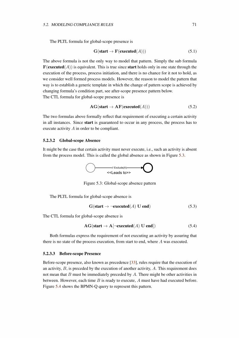
5.2. MODELING COMPLIANCE RULES 71
The PLTL formula for global-scope presence is
G(start → F(executed(A))) (5.1)
The above formula is not the only way to model that pattern. Simply the sub formulaF(executed(A)) is equivalent. This is true since start holds only in one state through theexecution of the process, process initiation, and there is no chance for it not to hold, aswe consider well formed process models. However, the reason to model the pattern thatway is to establish a generic template in which the change of pattern scope is achieved bychanging formula’s condition part, see after-scope presence pattern below.The CTL formula for global-scope presence is
AG(start → AF(executed(A))) (5.2)
The two formulas above formally reflect that requirement of executing a certain activityin all instances. Since start is guaranteed to occur in any process, the process has toexecute activity A in order to be compliant.
5.2.3.2 Global-scope Absence
It might be the case that certain activity must never execute, i.e., such an activity is absentfrom the process model. This is called the global absence as shown in Figure 5.3.
Figure 5.3: Global-scope absence pattern
The PLTL formula for global-scope absence is
G(start → ¬executed(A)U end) (5.3)
The CTL formula for global-scope absence is
AG(start → A[¬executed(A) U end]) (5.4)
Both formulas express the requirement of not executing an activity by assuring thatthere is no state of the process execution, from start to end, where A was executed.
5.2.3.3 Before-scope Presence
Before-scope presence, also known as precedence [33], rules require that the execution ofan activity, B, is preceded by the execution of another activity, A. This requirement doesnot mean that B must be immediately preceded by A. There might be other activities inbetween. However, each time B is ready to execute, A must have had executed before.Figure 5.4 shows the BPMN-Q query to represent this pattern.
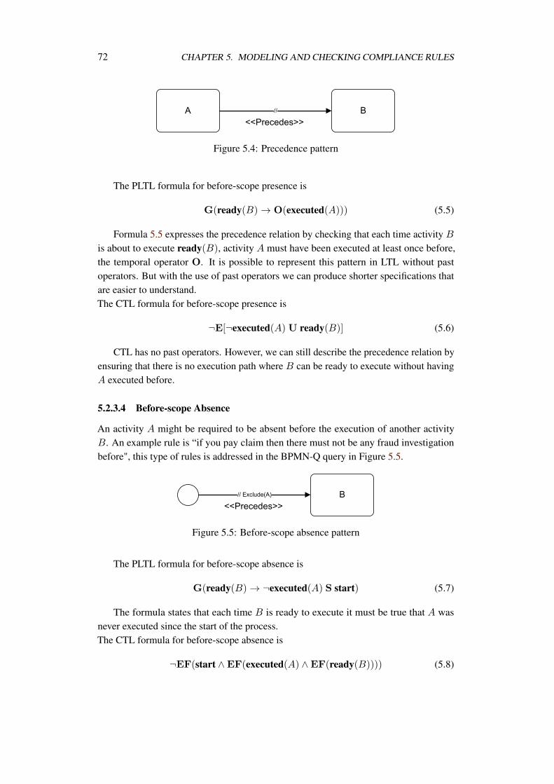
72 CHAPTER 5. MODELING AND CHECKING COMPLIANCE RULES
Figure 5.4: Precedence pattern
The PLTL formula for before-scope presence is
G(ready(B) → O(executed(A))) (5.5)
Formula 5.5 expresses the precedence relation by checking that each time activity B
is about to execute ready(B), activity A must have been executed at least once before,the temporal operator O. It is possible to represent this pattern in LTL without pastoperators. But with the use of past operators we can produce shorter specifications thatare easier to understand.The CTL formula for before-scope presence is
¬E[¬executed(A)U ready(B)] (5.6)
CTL has no past operators. However, we can still describe the precedence relation byensuring that there is no execution path where B can be ready to execute without havingA executed before.
5.2.3.4 Before-scope Absence
An activity A might be required to be absent before the execution of another activityB. An example rule is “if you pay claim then there must not be any fraud investigationbefore", this type of rules is addressed in the BPMN-Q query in Figure 5.5.
Figure 5.5: Before-scope absence pattern
The PLTL formula for before-scope absence is
G(ready(B) → ¬executed(A) S start) (5.7)
The formula states that each time B is ready to execute it must be true that A wasnever executed since the start of the process.The CTL formula for before-scope absence is
¬EF(start ∧EF(executed(A) ∧EF(ready(B)))) (5.8)
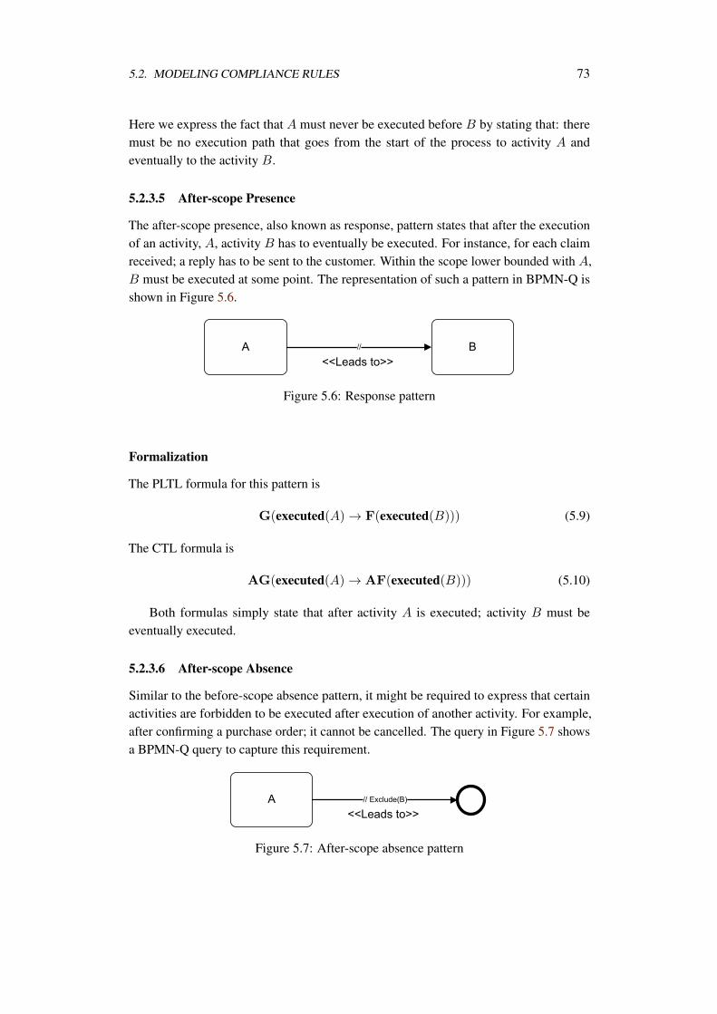
5.2. MODELING COMPLIANCE RULES 73
Here we express the fact that A must never be executed before B by stating that: theremust be no execution path that goes from the start of the process to activity A andeventually to the activity B.
5.2.3.5 After-scope Presence
The after-scope presence, also known as response, pattern states that after the executionof an activity, A, activity B has to eventually be executed. For instance, for each claimreceived; a reply has to be sent to the customer. Within the scope lower bounded with A,B must be executed at some point. The representation of such a pattern in BPMN-Q isshown in Figure 5.6.
Figure 5.6: Response pattern
Formalization
The PLTL formula for this pattern is
G(executed(A) → F(executed(B))) (5.9)
The CTL formula is
AG(executed(A) → AF(executed(B))) (5.10)
Both formulas simply state that after activity A is executed; activity B must beeventually executed.
5.2.3.6 After-scope Absence
Similar to the before-scope absence pattern, it might be required to express that certainactivities are forbidden to be executed after execution of another activity. For example,after confirming a purchase order; it cannot be cancelled. The query in Figure 5.7 showsa BPMN-Q query to capture this requirement.
Figure 5.7: After-scope absence pattern
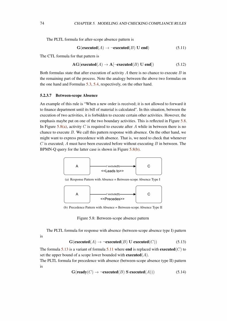
74 CHAPTER 5. MODELING AND CHECKING COMPLIANCE RULES
The PLTL formula for after-scope absence pattern is
G(executed(A) → ¬executed(B)U end) (5.11)
The CTL formula for that pattern is
AG(executed(A) → A[¬executed(B) U end]) (5.12)
Both formulas state that after execution of activity A there is no chance to execute B inthe remaining part of the process. Note the analogy between the above two formulas onthe one hand and Formulas 5.3, 5.4, respectively, on the other hand.
5.2.3.7 Between-scope Absence
An example of this rule is “When a new order is received; it is not allowed to forward itto finance department until its bill of material is calculated". In this situation, between theexecution of two activities, it is forbidden to execute certain other activities. However, theemphasis maybe put on one of the two boundary activities. This is reflected in Figure 5.8.In Figure 5.8(a), activity C is required to execute after A while in between there is nochance to execute B. We call this pattern response with absence. On the other hand, wemight want to express precedence with absence. That is, we need to check that wheneverC is executed; A must have been executed before without executing B in between. TheBPMN-Q query for the latter case is shown in Figure 5.8(b).
(a) Response Pattern with Absence = Between-scope Absence Type I
(b) Precedence Pattern with Absence = Between-scope Absence Type II
Figure 5.8: Between-scope absence pattern
The PLTL formula for response with absence (between-scope absence type I) patternis
G(executed(A) → ¬executed(B)U executed(C)) (5.13)
The formula 5.13 is a variant of formula 5.11 where end is replaced with executed(C) toset the upper bound of a scope lower bounded with executed(A).The PLTL formula for precedence with absence (between-scope absence type II) patternis
G(ready(C) → ¬executed(B) S executed(A))) (5.14)
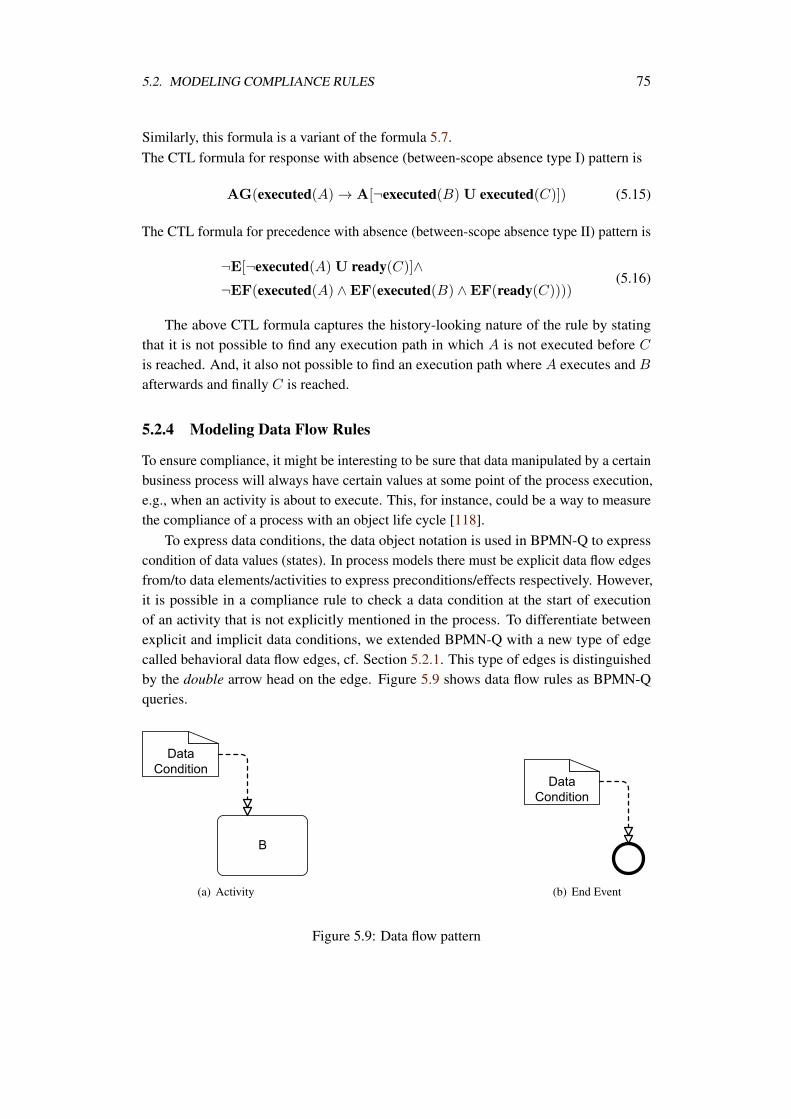
5.2. MODELING COMPLIANCE RULES 75
Similarly, this formula is a variant of the formula 5.7.The CTL formula for response with absence (between-scope absence type I) pattern is
AG(executed(A) → A[¬executed(B) U executed(C)]) (5.15)
The CTL formula for precedence with absence (between-scope absence type II) pattern is
¬E[¬executed(A)U ready(C)]∧¬EF(executed(A) ∧EF(executed(B) ∧EF(ready(C))))
(5.16)
The above CTL formula captures the history-looking nature of the rule by statingthat it is not possible to find any execution path in which A is not executed before C
is reached. And, it also not possible to find an execution path where A executes and B
afterwards and finally C is reached.
5.2.4 Modeling Data Flow Rules
To ensure compliance, it might be interesting to be sure that data manipulated by a certainbusiness process will always have certain values at some point of the process execution,e.g., when an activity is about to execute. This, for instance, could be a way to measurethe compliance of a process with an object life cycle [118].
To express data conditions, the data object notation is used in BPMN-Q to expresscondition of data values (states). In process models there must be explicit data flow edgesfrom/to data elements/activities to express preconditions/effects respectively. However,it is possible in a compliance rule to check a data condition at the start of executionof an activity that is not explicitly mentioned in the process. To differentiate betweenexplicit and implicit data conditions, we extended BPMN-Q with a new type of edgecalled behavioral data flow edges, cf. Section 5.2.1. This type of edges is distinguishedby the double arrow head on the edge. Figure 5.9 shows data flow rules as BPMN-Qqueries.
(a) Activity (b) End Event
Figure 5.9: Data flow pattern
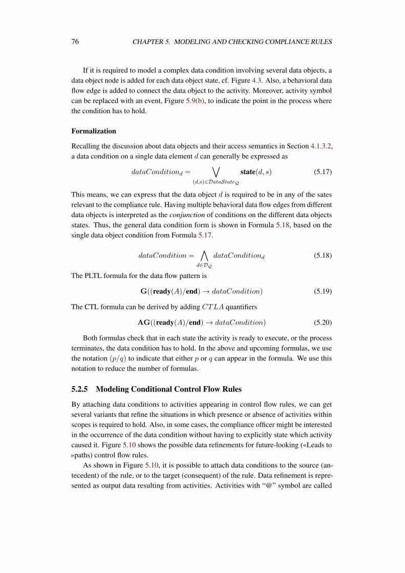
76 CHAPTER 5. MODELING AND CHECKING COMPLIANCE RULES
If it is required to model a complex data condition involving several data objects, adata object node is added for each data object state, cf. Figure 4.3. Also, a behavioral dataflow edge is added to connect the data object to the activity. Moreover, activity symbolcan be replaced with an event, Figure 5.9(b), to indicate the point in the process wherethe condition has to hold.
Formalization
Recalling the discussion about data objects and their access semantics in Section 4.1.3.2,a data condition on a single data element d can generally be expressed as
dataConditiond =
(d,s)∈DataStateQ
state(d, s) (5.17)
This means, we can express that the data object d is required to be in any of the satesrelevant to the compliance rule. Having multiple behavioral data flow edges from differentdata objects is interpreted as the conjunction of conditions on the different data objectsstates. Thus, the general data condition form is shown in Formula 5.18, based on thesingle data object condition from Formula 5.17.
dataCondition =
d∈DQ
dataConditiond (5.18)
The PLTL formula for the data flow pattern is
G((ready(A)/end) → dataCondition) (5.19)
The CTL formula can be derived by adding CTLA quantifiers
AG((ready(A)/end) → dataCondition) (5.20)
Both formulas check that in each state the activity is ready to execute, or the processterminates, the data condition has to hold. In the above and upcoming formulas, we usethe notation (p/q) to indicate that either p or q can appear in the formula. We use thisnotation to reduce the number of formulas.
5.2.5 Modeling Conditional Control Flow Rules
By attaching data conditions to activities appearing in control flow rules, we can getseveral variants that refine the situations in which presence or absence of activities withinscopes is required to hold. Also, in some cases, the compliance officer might be interestedin the occurrence of the data condition without having to explicitly state which activitycaused it. Figure 5.10 shows the possible data refinements for future-looking («Leads to»paths) control flow rules.
As shown in Figure 5.10, it is possible to attach data conditions to the source (an-tecedent) of the rule, or to the target (consequent) of the rule. Data refinement is repre-sented as output data resulting from activities. Activities with “@” symbol are called
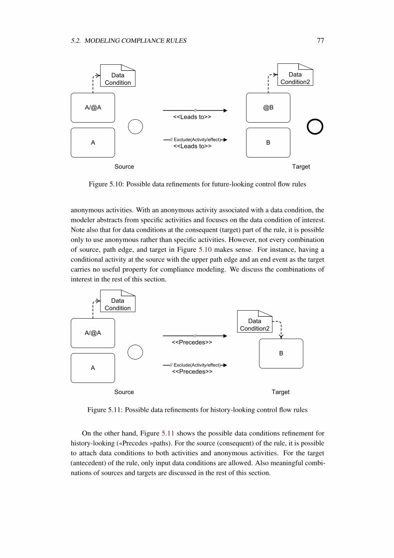
5.2. MODELING COMPLIANCE RULES 77
Figure 5.10: Possible data refinements for future-looking control flow rules
anonymous activities. With an anonymous activity associated with a data condition, themodeler abstracts from specific activities and focuses on the data condition of interest.Note also that for data conditions at the consequent (target) part of the rule, it is possibleonly to use anonymous rather than specific activities. However, not every combinationof source, path edge, and target in Figure 5.10 makes sense. For instance, having aconditional activity at the source with the upper path edge and an end event as the targetcarries no useful property for compliance modeling. We discuss the combinations ofinterest in the rest of this section.
Figure 5.11: Possible data refinements for history-looking control flow rules
On the other hand, Figure 5.11 shows the possible data conditions refinement forhistory-looking («Precedes »paths). For the source (consequent) of the rule, it is possibleto attach data conditions to both activities and anonymous activities. For the target(antecedent) of the rule, only input data conditions are allowed. Also meaningful combi-nations of sources and targets are discussed in the rest of this section.
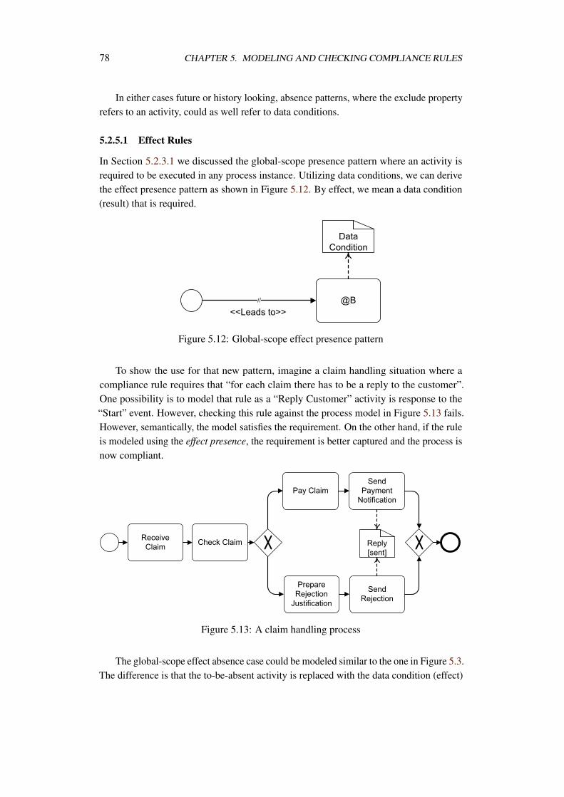
78 CHAPTER 5. MODELING AND CHECKING COMPLIANCE RULES
In either cases future or history looking, absence patterns, where the exclude propertyrefers to an activity, could as well refer to data conditions.
5.2.5.1 Effect Rules
In Section 5.2.3.1 we discussed the global-scope presence pattern where an activity isrequired to be executed in any process instance. Utilizing data conditions, we can derivethe effect presence pattern as shown in Figure 5.12. By effect, we mean a data condition(result) that is required.
Figure 5.12: Global-scope effect presence pattern
To show the use for that new pattern, imagine a claim handling situation where acompliance rule requires that “for each claim there has to be a reply to the customer”.One possibility is to model that rule as a “Reply Customer” activity is response to the“Start” event. However, checking this rule against the process model in Figure 5.13 fails.However, semantically, the model satisfies the requirement. On the other hand, if the ruleis modeled using the effect presence, the requirement is better captured and the process isnow compliant.
Figure 5.13: A claim handling process
The global-scope effect absence case could be modeled similar to the one in Figure 5.3.The difference is that the to-be-absent activity is replaced with the data condition (effect)
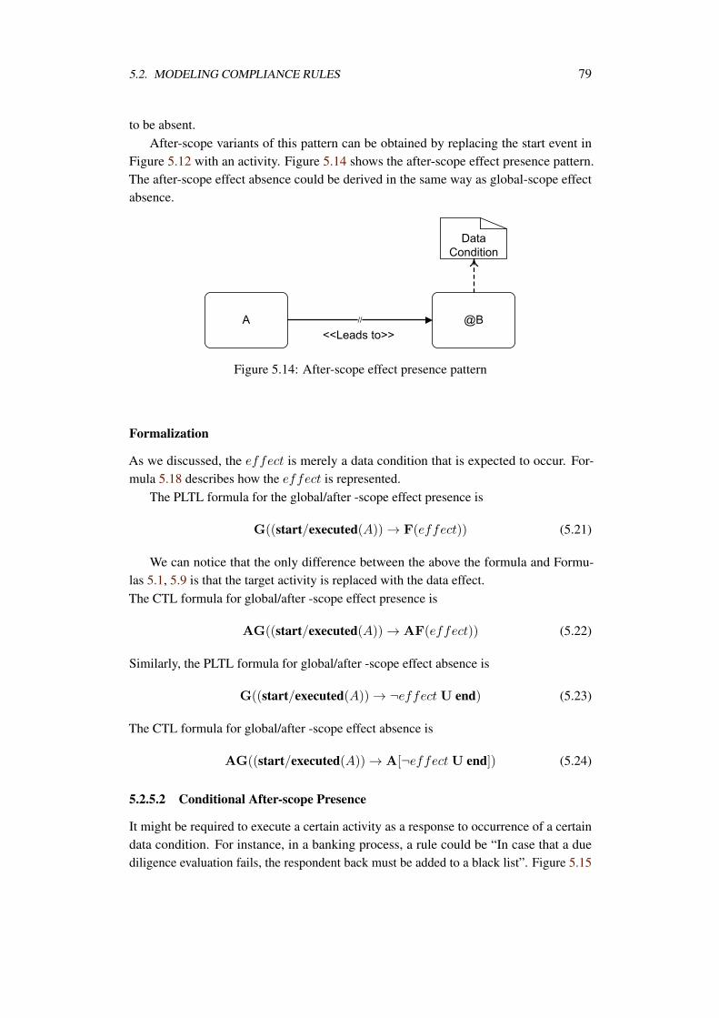
5.2. MODELING COMPLIANCE RULES 79
to be absent.After-scope variants of this pattern can be obtained by replacing the start event in
Figure 5.12 with an activity. Figure 5.14 shows the after-scope effect presence pattern.The after-scope effect absence could be derived in the same way as global-scope effectabsence.
Figure 5.14: After-scope effect presence pattern
Formalization
As we discussed, the effect is merely a data condition that is expected to occur. For-mula 5.18 describes how the effect is represented.
The PLTL formula for the global/after -scope effect presence is
G((start/executed(A)) → F(effect)) (5.21)
We can notice that the only difference between the above the formula and Formu-las 5.1, 5.9 is that the target activity is replaced with the data effect.The CTL formula for global/after -scope effect presence is
AG((start/executed(A)) → AF(effect)) (5.22)
Similarly, the PLTL formula for global/after -scope effect absence is
G((start/executed(A)) → ¬effect U end) (5.23)
The CTL formula for global/after -scope effect absence is
AG((start/executed(A)) → A[¬effect U end]) (5.24)
5.2.5.2 Conditional After-scope Presence
It might be required to execute a certain activity as a response to occurrence of a certaindata condition. For instance, in a banking process, a rule could be “In case that a duediligence evaluation fails, the respondent back must be added to a black list”. Figure 5.15
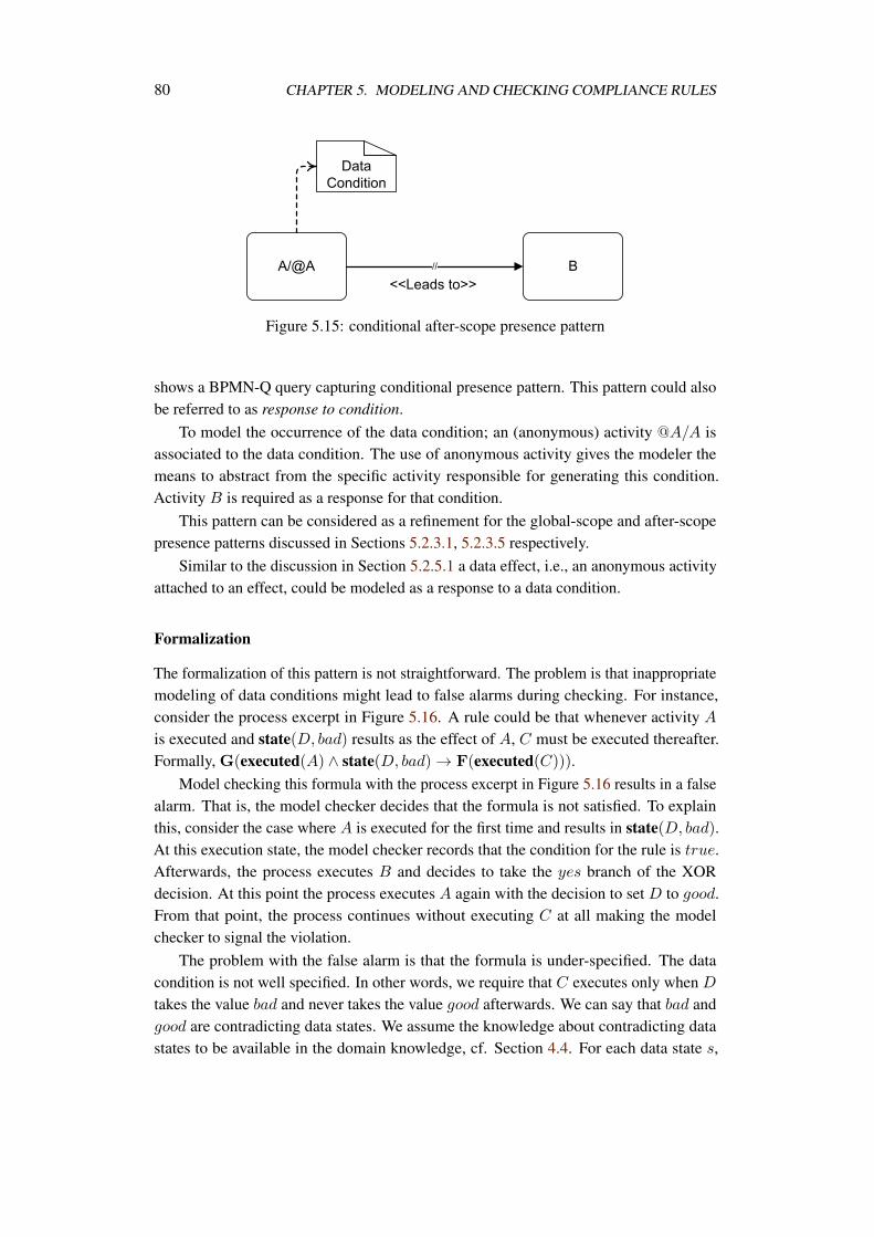
80 CHAPTER 5. MODELING AND CHECKING COMPLIANCE RULES
Figure 5.15: conditional after-scope presence pattern
shows a BPMN-Q query capturing conditional presence pattern. This pattern could alsobe referred to as response to condition.
To model the occurrence of the data condition; an (anonymous) activity @A/A isassociated to the data condition. The use of anonymous activity gives the modeler themeans to abstract from the specific activity responsible for generating this condition.Activity B is required as a response for that condition.
This pattern can be considered as a refinement for the global-scope and after-scopepresence patterns discussed in Sections 5.2.3.1, 5.2.3.5 respectively.
Similar to the discussion in Section 5.2.5.1 a data effect, i.e., an anonymous activityattached to an effect, could be modeled as a response to a data condition.
Formalization
The formalization of this pattern is not straightforward. The problem is that inappropriatemodeling of data conditions might lead to false alarms during checking. For instance,consider the process excerpt in Figure 5.16. A rule could be that whenever activity A
is executed and state(D, bad) results as the effect of A, C must be executed thereafter.Formally, G(executed(A) ∧ state(D, bad) → F(executed(C))).
Model checking this formula with the process excerpt in Figure 5.16 results in a falsealarm. That is, the model checker decides that the formula is not satisfied. To explainthis, consider the case where A is executed for the first time and results in state(D, bad).At this execution state, the model checker records that the condition for the rule is true.Afterwards, the process executes B and decides to take the yes branch of the XORdecision. At this point the process executes A again with the decision to set D to good.From that point, the process continues without executing C at all making the modelchecker to signal the violation.
The problem with the false alarm is that the formula is under-specified. The datacondition is not well specified. In other words, we require that C executes only when D
takes the value bad and never takes the value good afterwards. We can say that bad andgood are contradicting data states. We assume the knowledge about contradicting datastates to be available in the domain knowledge, cf. Section 4.4. For each data state s,
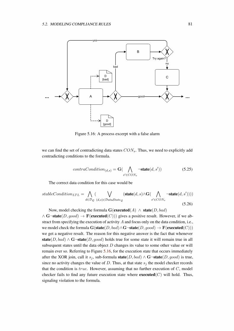
5.2. MODELING COMPLIANCE RULES 81
Figure 5.16: A process excerpt with a false alarm
we can find the set of contradicting data states CONs. Thus, we need to explicitly addcontradicting conditions to the formula.
contraCondition(d,s) = G(
s′∈CONs
¬state(d, s′)) (5.25)
The correct data condition for this case would be
stableConditionLTL =
d∈DQ
(
(d,s)∈DataStateQ
(state(d, s)∧G(
s′∈CONs
¬state(d, s′))))
(5.26)Now, model checking the formula G(executed(A) ∧ state(D, bad)
∧ G¬state(D, good) → F(executed(C))) gives a positive result. However, if we ab-stract from specifying the execution of activity A and focus only on the data condition, i.e.,we model check the formula G(state(D, bad)∧G¬state(D, good) → F(executed(C)))
we get a negative result. The reason for this negative answer is the fact that wheneverstate(D, bad) ∧ G¬state(D, good) holds true for some state it will remain true in allsubsequent states until the data object D changes its value to some other value or willremain ever so. Referring to Figure 5.16, for the execution state that occurs immediatelyafter the XOR join, call it sj , sub-formula state(D, bad) ∧ G¬state(D, good) is true,since no activity changes the value of D. Thus, at that state sj the model checker recordsthat the condition is true. However, assuming that no further execution of C, modelchecker fails to find any future execution state where executed(C) will hold. Thus,signaling violation to the formula.
82 CHAPTER 5. MODELING AND CHECKING COMPLIANCE RULES
Conceptually, the model is correct since C is executed in response to the first occur-rence of the data condition state(D, bad) ∧G¬state(D, good). The fact that the datacondition holds true afterwards must not indicate failure. There are two possibilities to getrid of this false alarm. The first way is to be sure of having the predicate executed(act)always as part of the rule’s condition. Even if the user uses an anonymous activity atrule specification time, it is always possible at checking time against a specific processmodel to resolve the activity(ies) that generate that data condition. Assuming a functionupdate(d,s) that returns all activities in a process model that update the data object dto the state (value) s, we can have the following representation of conditional presencepattern.The PLTL formula for conditional presence pattern is
G((
A∈
(d,s)∈DataStateQupdate(d,s)
executed(A)) ∧ stableConditionLTL →
F(executed(B)/effect)) (5.27)
The stableConditionLTL in the above formula refers to Formula 5.26. In all subse-quent formulas where stableDataConditionLTL appears, it refers to Formula 5.26.
The same correct data condition above can be used within CTL formulas. However, asmall syntactical change has to be done by adding the for all quantifier before the globaloperator.
stableConditionCTL =
d∈DQ
(
(d,s)∈DataStateQ
(state(d, s)∧AG(
s′∈CONs
¬state(d, s′))))
(5.28)The CTL formula for conditional presence pattern is
AG((
A∈
(d,s)∈DataStateQupdate(d,s)
executed(A)) ∧ stableConditionCTL →
AF(executed(B)/effect)) (5.29)
The stableConditionCTL in the above formula refers to Formula 5.28. In all subse-quent formulas where stableDataConditionCTL appears, it refers to Formula 5.28.
The other possibility to reflect that response is needed only for the first occurrenceof the data condition, in case that the user abstracts from a specific activity, is to ex-plicitly model that in the temporal logic formula. Referring to the process excerpt ofFigure 5.16 and the LTL formula we had so far G(state(D, bad)∧G¬state(D, good) →F(executed(C))), we can modify that LTL formula to look like G(state(D, bad) ∧G¬state(D, good) ∧ ¬O(state(D, bad) ∧ G¬state(D, good)) → F(executed(C))).We modified the condition of the formula by looking for the very first state in which thedata condition holds. That is the state which is not preceded by any other state where thedata condition held. To represent the checking for the first state in which the data condition
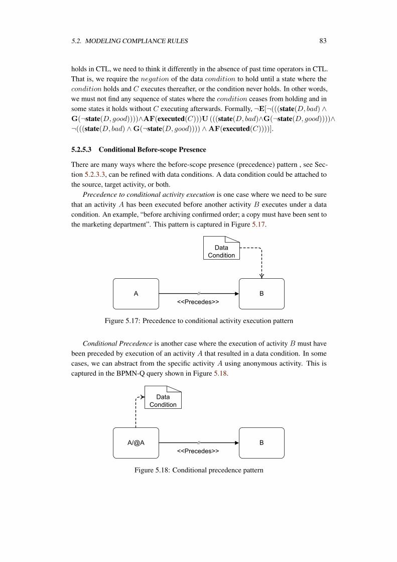
5.2. MODELING COMPLIANCE RULES 83
holds in CTL, we need to think it differently in the absence of past time operators in CTL.That is, we require the negation of the data condition to hold until a state where thecondition holds and C executes thereafter, or the condition never holds. In other words,we must not find any sequence of states where the condition ceases from holding and insome states it holds without C executing afterwards. Formally, ¬E[¬(((state(D, bad) ∧G(¬state(D, good))))∧AF(executed(C)))U (((state(D, bad)∧G(¬state(D, good))))∧¬(((state(D, bad) ∧G(¬state(D, good)))) ∧AF(executed(C))))].
5.2.5.3 Conditional Before-scope Presence
There are many ways where the before-scope presence (precedence) pattern , see Sec-tion 5.2.3.3, can be refined with data conditions. A data condition could be attached tothe source, target activity, or both.
Precedence to conditional activity execution is one case where we need to be surethat an activity A has been executed before another activity B executes under a datacondition. An example, “before archiving confirmed order; a copy must have been sent tothe marketing department”. This pattern is captured in Figure 5.17.
Figure 5.17: Precedence to conditional activity execution pattern
Conditional Precedence is another case where the execution of activity B must havebeen preceded by execution of an activity A that resulted in a data condition. In somecases, we can abstract from the specific activity A using anonymous activity. This iscaptured in the BPMN-Q query shown in Figure 5.18.
Figure 5.18: Conditional precedence pattern
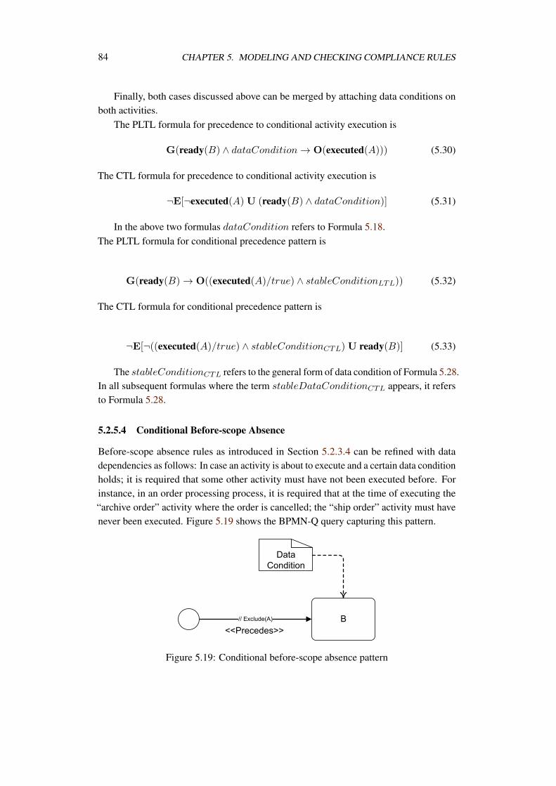
84 CHAPTER 5. MODELING AND CHECKING COMPLIANCE RULES
Finally, both cases discussed above can be merged by attaching data conditions onboth activities.
The PLTL formula for precedence to conditional activity execution is
G(ready(B) ∧ dataCondition → O(executed(A))) (5.30)
The CTL formula for precedence to conditional activity execution is
¬E[¬executed(A)U (ready(B) ∧ dataCondition)] (5.31)
In the above two formulas dataCondition refers to Formula 5.18.The PLTL formula for conditional precedence pattern is
G(ready(B) → O((executed(A)/true) ∧ stableConditionLTL)) (5.32)
The CTL formula for conditional precedence pattern is
¬E[¬((executed(A)/true) ∧ stableConditionCTL) U ready(B)] (5.33)
The stableConditionCTL refers to the general form of data condition of Formula 5.28.In all subsequent formulas where the term stableDataConditionCTL appears, it refersto Formula 5.28.
5.2.5.4 Conditional Before-scope Absence
Before-scope absence rules as introduced in Section 5.2.3.4 can be refined with datadependencies as follows: In case an activity is about to execute and a certain data conditionholds; it is required that some other activity must have not been executed before. Forinstance, in an order processing process, it is required that at the time of executing the“archive order” activity where the order is cancelled; the “ship order” activity must havenever been executed. Figure 5.19 shows the BPMN-Q query capturing this pattern.
Figure 5.19: Conditional before-scope absence pattern
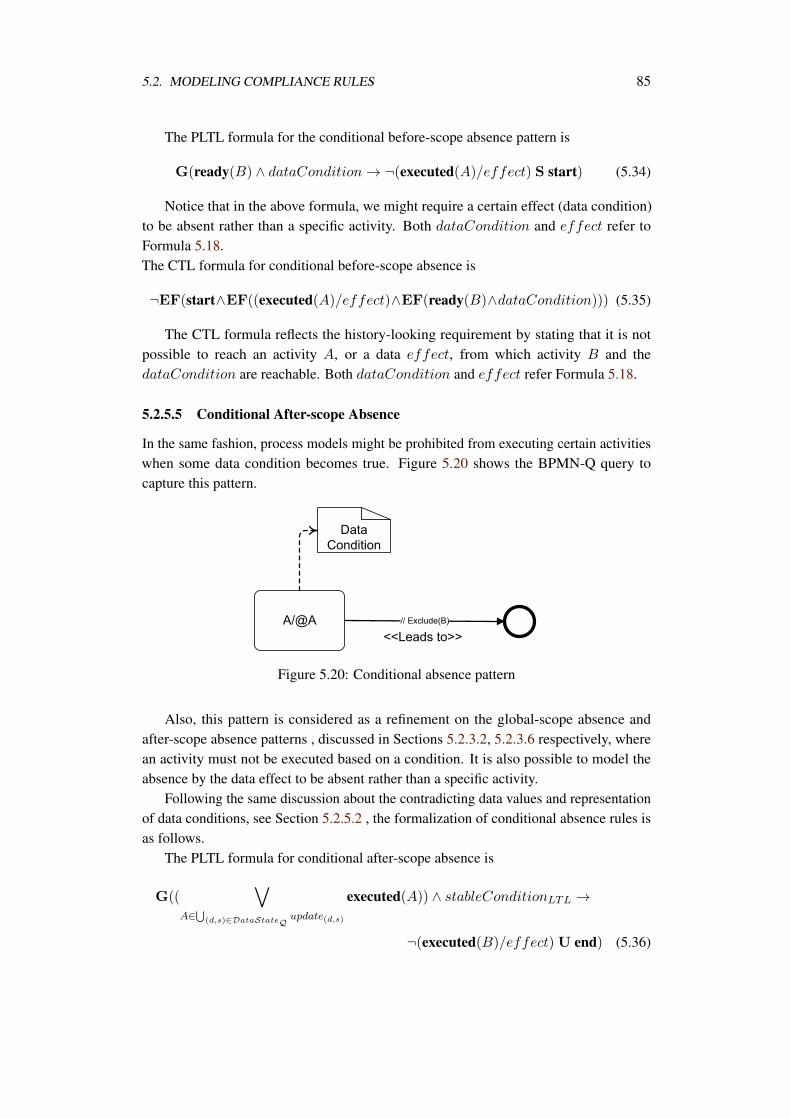
5.2. MODELING COMPLIANCE RULES 85
The PLTL formula for the conditional before-scope absence pattern is
G(ready(B) ∧ dataCondition → ¬(executed(A)/effect) S start) (5.34)
Notice that in the above formula, we might require a certain effect (data condition)to be absent rather than a specific activity. Both dataCondition and effect refer toFormula 5.18.The CTL formula for conditional before-scope absence is
¬EF(start∧EF((executed(A)/effect)∧EF(ready(B)∧dataCondition))) (5.35)
The CTL formula reflects the history-looking requirement by stating that it is notpossible to reach an activity A, or a data effect, from which activity B and thedataCondition are reachable. Both dataCondition and effect refer Formula 5.18.
5.2.5.5 Conditional After-scope Absence
In the same fashion, process models might be prohibited from executing certain activitieswhen some data condition becomes true. Figure 5.20 shows the BPMN-Q query tocapture this pattern.
Figure 5.20: Conditional absence pattern
Also, this pattern is considered as a refinement on the global-scope absence andafter-scope absence patterns , discussed in Sections 5.2.3.2, 5.2.3.6 respectively, wherean activity must not be executed based on a condition. It is also possible to model theabsence by the data effect to be absent rather than a specific activity.
Following the same discussion about the contradicting data values and representationof data conditions, see Section 5.2.5.2 , the formalization of conditional absence rules isas follows.
The PLTL formula for conditional after-scope absence is
G((
A∈
(d,s)∈DataStateQupdate(d,s)
executed(A)) ∧ stableConditionLTL →
¬(executed(B)/effect) U end) (5.36)
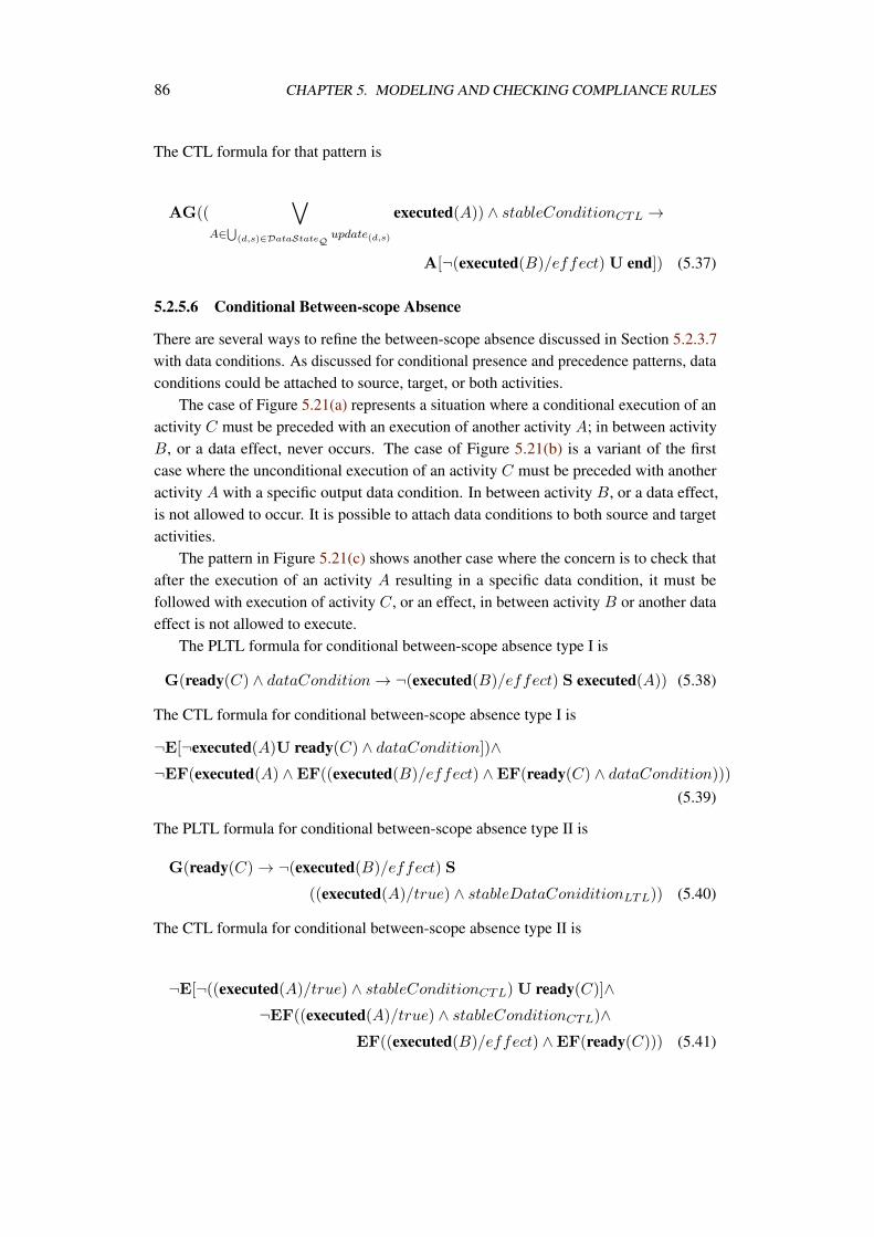
86 CHAPTER 5. MODELING AND CHECKING COMPLIANCE RULES
The CTL formula for that pattern is
AG((
A∈
(d,s)∈DataStateQupdate(d,s)
executed(A)) ∧ stableConditionCTL →
A[¬(executed(B)/effect) U end]) (5.37)
5.2.5.6 Conditional Between-scope Absence
There are several ways to refine the between-scope absence discussed in Section 5.2.3.7with data conditions. As discussed for conditional presence and precedence patterns, dataconditions could be attached to source, target, or both activities.
The case of Figure 5.21(a) represents a situation where a conditional execution of anactivity C must be preceded with an execution of another activity A; in between activityB, or a data effect, never occurs. The case of Figure 5.21(b) is a variant of the firstcase where the unconditional execution of an activity C must be preceded with anotheractivity A with a specific output data condition. In between activity B, or a data effect,is not allowed to occur. It is possible to attach data conditions to both source and targetactivities.
The pattern in Figure 5.21(c) shows another case where the concern is to check thatafter the execution of an activity A resulting in a specific data condition, it must befollowed with execution of activity C, or an effect, in between activity B or another dataeffect is not allowed to execute.
The PLTL formula for conditional between-scope absence type I is
G(ready(C) ∧ dataCondition → ¬(executed(B)/effect) S executed(A)) (5.38)
The CTL formula for conditional between-scope absence type I is
¬E[¬executed(A)U ready(C) ∧ dataCondition])∧¬EF(executed(A) ∧EF((executed(B)/effect) ∧EF(ready(C) ∧ dataCondition)))
(5.39)
The PLTL formula for conditional between-scope absence type II is
G(ready(C) → ¬(executed(B)/effect) S
((executed(A)/true) ∧ stableDataConiditionLTL)) (5.40)
The CTL formula for conditional between-scope absence type II is
¬E[¬((executed(A)/true) ∧ stableConditionCTL) U ready(C)]∧¬EF((executed(A)/true) ∧ stableConditionCTL)∧
EF((executed(B)/effect) ∧EF(ready(C))) (5.41)
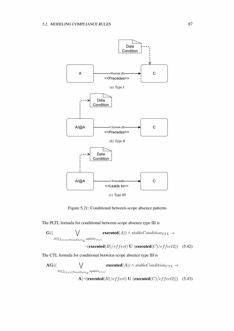
5.2. MODELING COMPLIANCE RULES 87
(a) Type I
(b) Type II
(c) Type III
Figure 5.21: Conditional between-scope absence patterns
The PLTL formula for conditional between-scope absence type III is
G((
A∈
(d,s)∈DataStateQupdate(d,s)
executed(A)) ∧ stableConditionLTL →
¬(executed(B)/effect) U (executed(C)/effect2)) (5.42)
The CTL formula for conditional between-scope absence type III is
AG((
A∈
(d,s)∈DataStateQupdate(d,s)
executed(A)) ∧ stableConditionCTL →
A[¬(executed(B)/effect) U (executed(C)/effect2)]) (5.43)
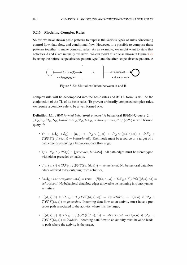
88 CHAPTER 5. MODELING AND CHECKING COMPLIANCE RULES
5.2.6 Modeling Complex Rules
So far, we have shown basic patterns to express the various types of rules concerningcontrol flow, data flow, and conditional flow. However, it is possible to compose thesepatterns together to make complex rules. As an example, we might want to state thatactivities A and B are mutually exclusive. We can model this rule as shown in Figure 5.22by using the before-scope absence pattern type I and the after-scope absence pattern. A
Figure 5.22: Mutual exclusion between A and B
complex rule will be decomposed into the basic rules and its TL formula will be theconjunction of the TL of its basic rules. To prevent arbitrarily composed complex rules,we require a complex rule to be a well formed one.
Definition 5.1. [Well formed behavioral queries] A behavioral BPMN-Q query Q =
(AQ, EQ,DQ,SQ,DataStateQ,PQ,DFQ, isAnonymous,X , T YPE) is well formedquery if:
• ∀n ∈ (AQ ∪ EQ) : (n, _) ∈ PQ ∨ (_, n) ∈ PQ ∨ (((d, s), n) ∈ DFQ :
T YPE(((d, s), n)) = behavioral). Each node must be a source or a target of apath edge or receiving a behavioral data flow edge,
• ∀p ∈ PQ T YPE(p) ∈ precedes, leadsto. All path edges must be stereotypedwith either precedes or leads to,
• ∀(a, (d, s)) ∈ DFQ : T YPE((a, (d, s))) = structural. No behavioral data flowedges allowed to be outgoing from activities,
• ∃aAQ : isAnonyomous(a) = true → ∃((d, s), a) ∈ DFQ : T YPE(((d, s), a)) =behavioral. No behavioral data flow edges allowed to be incoming into anonymousactivities,
• ∃((d, s), a) ∈ DFQ : T YPE(((d, s), a)) = structural → ∃(o, a) ∈ PQ :
T YPE((o, a)) = precedes. Incoming data flow to an activity must have a pre-cedes path associated to the activity where it is the target,
• ∃((d, s), a) ∈ DFQ : T YPE(((d, s), a)) = structural → ∃(o, a) ∈ PQ :
T YPE((o, a)) = leadsto. Incoming data flow to an activity must have no leadsto path where the activity is the target,
5.3. CONSISTENCY CHECKING AMONG RULES 89
• ∃(a, (d, s)) ∈ DFQ ∧ T YPE((a, (d, s))) = structural∧ isAnonymous(a) =
true → ∃(o, a) ∈ PQ ∧ T YPE((o, a)) = precedes. Outgoing data flow froman anonymous activity must have no precedes path where the activity is the target.
• ∀s ∈ EQs : @(o, s) ∈ PQ. Start events cannot be targets to any path edge.
• ∀e ∈ EQe : @(e, o) ∈ PQ. End events cannot be sources to any path edge.
• ∀(o, e) ∈ PQ : e ∈ EQe → T YPE((o, e)) = leadsto ∧ X (o, e) = ∅. An endevent in a query can be only a target of a leads to path and the exclude property ofthe path edge must not be empty.
5.3 Consistency Checking Among Rules
With the divergent sources of compliance requirements, it is likely to have redundantor conflicting compliance requirements [19]. Redundant requirements would consumemore effort verifying the same property. On the other hand, conflicting requirementswould consume a lot of effort before figuring out that it is not possible to satisfy themcollectively.
While it is hard to derive a consistent subset of rules, it is inevitable to check forinconsistency [49]. In Section 5.3.1 we discuss various types of redundancy and how tocheck them. In Section 5.3.2 we address the issue of conflict detection and provide meansto decide about conflicts.
Recall that Q is the set of all BPMN-Q queries, P is the set of all business processmodels and TAG is the set of all tags that can be used to annotate queries and processes.
Definition 5.2. [Related compliance rules] for a specific set of tags T ⊆ TAG the setqT ⊂ Q contains all queries that are assigned this set of tags, ∀q ∈ qT(T ⊆ annotate(q))
Definition 5.2 states that qT contains compliance rules (queries) that have the sameset of tags. Therefore, the requirements imposed by these rules have to be checked forconsistency before proceeding to check them against process models.
5.3.1 Redundancy Checking
Redundancy occurs when two or more rules are logically equivalent [49]. Deciding aboutredundant rules helps remove them from checking and save effort without losing anycompliance requirement.
Definition 5.3. [Redundancy] A rule ri is redundant within rule set R if and only if forany arbitrary process model p: p |=
rk∈R\ri rk ↔ p |=
rj∈R rj
According to Definition 5.3 the redundancy is a property for a collection of compliancerules and is independent from the set of process models under investigation.
90 CHAPTER 5. MODELING AND CHECKING COMPLIANCE RULES
Considering the compliance patterns discussed in Section 5.2, redundancy can occurin any of the following situations:
1. (Duplication) Two rules R1 and R2 state the same requirements. This might occurdue to two different developments of compliance rules.
2. (Subsumption) An example is a response pattern R1 on the form G(executed(a) →F(executed(b))) that is subsumed by a between-scope absence rule R2 on the formG(executed(a) → ¬executed(c)U executed(b)).
3. (Mutual Exclusion) A rule R1: G(executed(a) → (¬executed(b)S start) ∧(¬executed(b)U end)) is redundant to R2 : G(executed(b) →(¬executed(a)S start)∧(¬executed(a)U end)) since R1 states that executed(a)and executed(b) are mutually exclusive. R2 also tells that executed(b) andexecuted(a) are mutually exclusive. The redundancy is because of the commuta-tive nature of mutual exclusion relation.
4. (Contrapositive) Two rules state the same requirements differently. For instance R1
states the “open account if the risk is low”; while R2 states “if risk is high neveropen an account”. This could be considered as a special type of mutual exclusionthat could be expressed in different ways.
In the first case, there is a duplication of rules and rules are equivalent. It is trivial todetect this case and only one copy of the rule is retained and all other copies are removed.
The subsumption case occurs when some rule states a stronger conclusion thanthe other. For instance a response rule R1:G(executed(a) → F(executed(b))) anda between-scope absence R2:G(executed(a) → ¬executed(c)U executed(b)). It isobvious that the satisfaction of R1 ∧R2 is determined by R2. That is, there is no chancethat R1 is false and R2 is true. Thus, R1 is unnecessary. For the case of mutual exclusion,it is sufficient to ensure that executed(a) is mutually exclusive to executed(b) withoutthe other way around. The last case is another sort of equivalence similar to logicalequivalence between an implication p → q and its contrapositive ¬q → ¬p.
Duplicate and mutual exclusion redundancy can be detected easily. However, sub-sumption and contrapositive redundancy need further investigation about different patternscausing them in addition to domain knowledge. It is necessary to get rid of redundantrules prior to checking them against process models in order to reduce checking effort.
In general, a rule R1 subsumes another rule R2 when the condition of R2 logicallyimplies the condition of R1, i.e., R1 has a weaker or equivalent condition than R2 andthe consequent of R1 logically implies the consequent of R2, i.e., R1 states a strongeror equivalent conclusion than R2. Table 5.1 summarizes the possible occurrences ofsubsumption redundancies among the compliance patterns discussed in Section 5.2.Notice that only patterns with possibility of subsumption redundancies are mentioned.
Obviously, every control flow pattern subsumes its conditional counterpart. For in-stance, an after-scope presence rule G(executed(a) → F(executed(b))) subsumes a con-
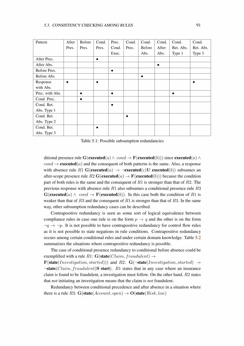
5.3. CONSISTENCY CHECKING AMONG RULES 91
Pattern After Before Cond. Prec. Cond. Cond. Cond. Cond. Cond.Pres. Pres. Pres. Cond. Prec. Before After Bet. Abs. Bet. Abs.
Exec. Abs. Abs. Type 1 Type 3After Pres. •After Abs. •Before Pres. •Before Abs. •Response • • •with Abs.Prec. with Abs. • • •Cond. Prec. •Cond. Bet. •Abs. Type 1Cond. Bet. •Abs. Type 2Cond. Bet. •Abs. Type 3
Table 5.1: Possible subsumption redundancies
ditional presence rule G(executed(a)∧ cond → F(executed(b))) since executed(a)∧cond → executed(a) and the consequent of both patterns is the same. Also, a responsewith absence rule R1 G(executed(a) → ¬executed(c)U executed(b)) subsumes anafter-scope presence rule R2 G(executed(a) → F(executed(b))) because the conditionpart of both rules is the same and the consequent of R1 is stronger than that of R2. Theprevious response with absence rule R1 also subsumes a conditional presence rule R3
G(executed(a) ∧ cond → F(executed(b)). In this case both the condition of R1 isweaker than that of R3 and the consequent of R1 is stronger than that of R3. In the sameway, other subsumption redundancy cases can be described.
Contrapositive redundancy is seen as some sort of logical equivalence betweencompliance rules in case one rule is on the form p → q and the other is on the form¬q → ¬p. It is not possible to have contrapositive redundancy for control flow rulesas it is not possible to state negations in rule conditions. Contrapositive redundancyoccurs among certain conditional rules and under certain domain knowledge. Table 5.2summarizes the situations where contrapositive redundancy is possible.
The case of conditional presence redundancy to conditional before absence could beexemplified with a rule R1: G(state(Claim, fraudulent) →F(state(Investigation, started))) and R2: G(¬state(Investigation, started) →¬state(Claim, fraudulent)S start). R1 states that in any case where an insuranceclaim is found to be fraudulent, a investigation must follow. On the other hand, R2 statesthat not initiating an investigation means that the claim is not fraudulent.
Redundancy between conditional precedence and after absence in a situation wherethere is a rule R3: G(state(Account, open) → O(state(Risk, low)
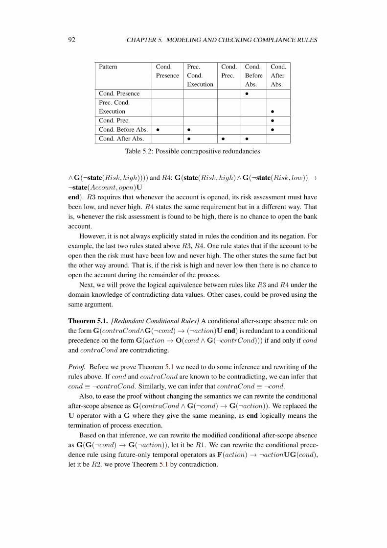
92 CHAPTER 5. MODELING AND CHECKING COMPLIANCE RULES
Pattern Cond. Prec. Cond. Cond. Cond.Presence Cond. Prec. Before After
Execution Abs. Abs.Cond. Presence •Prec. Cond.Execution •Cond. Prec. •Cond. Before Abs. • • •Cond. After Abs. • • •
Table 5.2: Possible contrapositive redundancies
∧G(¬state(Risk, high)))) and R4: G(state(Risk, high)∧G(¬state(Risk, low)) →¬state(Account, open)Uend). R3 requires that whenever the account is opened, its risk assessment must havebeen low, and never high. R4 states the same requirement but in a different way. Thatis, whenever the risk assessment is found to be high, there is no chance to open the bankaccount.
However, it is not always explicitly stated in rules the condition and its negation. Forexample, the last two rules stated above R3, R4. One rule states that if the account to beopen then the risk must have been low and never high. The other states the same fact butthe other way around. That is, if the risk is high and never low then there is no chance toopen the account during the remainder of the process.
Next, we will prove the logical equivalence between rules like R3 and R4 under thedomain knowledge of contradicting data values. Other cases, could be proved using thesame argument.
Theorem 5.1. [Redundant Conditional Rules] A conditional after-scope absence rule onthe form G(contraCond∧G(¬cond) → (¬action)U end) is redundant to a conditionalprecedence on the form G(action → O(cond ∧G(¬contrCond))) if and only if condand contraCond are contradicting.
Proof. Before we prove Theorem 5.1 we need to do some inference and rewriting of therules above. If cond and contraCond are known to be contradicting, we can infer thatcond ≡ ¬contraCond. Similarly, we can infer that contraCond ≡ ¬cond.
Also, to ease the proof without changing the semantics we can rewrite the conditionalafter-scope absence as G(contraCond ∧G(¬cond) → G(¬action)). We replaced theU operator with a G where they give the same meaning, as end logically means thetermination of process execution.
Based on that inference, we can rewrite the modified conditional after-scope absenceas G(G(¬cond) → G(¬action)), let it be R1. We can rewrite the conditional prece-dence rule using future-only temporal operators as F(action) → ¬actionUG(cond),let it be R2. we prove Theorem 5.1 by contradiction.
5.3. CONSISTENCY CHECKING AMONG RULES 93
Let a system M |= R1. Thus s0 |= R1. I.e., ∃sm : s0, . . . , sm ∧ cond /∈ L(sm) ∧action /∈ L(sm) and ∀sk that come after sm also cond /∈ L(sk) ∧ action /∈ L(sk).
Assume that M |= R2. Thus, ∃sv : s0, . . . , sv where sv is the very first statewhere action ∈ L(sv). Then, for M |= R2 to hold, there must be some state stwhere s0 . . . , st, . . . , sv ∧st |= G(cond). I.e., cond /∈ L(st). But, since M |= R1.We can derive that action /∈ L(st). and for all states that come after st, including sv,action /∈ L(sv). Thus we reach a contradiction where we require action ∈ L(sv) andaction /∈ L(sv)
5.3.2 Conflict Checking
While redundancy checking is needed to reduce effort, conflict checking is needed todecide the satisfiability of these related compliance requirements. For a conflict freeset of compliance rules, it is possible to find a process model that satisfies all of theserequirements.
To decide about conflict freedom, we utilize existing approaches for LTL modelchecking. We depend on the fact that for each LTL formula, it is possible to find acomputation that satisfies this formula, in case there is one. Thus, we can construct theconjunction of these individual LTL formula and look for a computation that satisfiesthem. However, we show that to reach a correct decision about conflict-freedom, we needto add extra information to the satisfiability check [15].
5.3.2.1 LTL to Büchi Automaton
It is possible for each LTL formula to generate a Büchi automaton that represents acomputation to satisfy the formula, if there is one. The Büchi automaton describessystems with infinite behavior. An LTL formula is satisfiable if its Büchi automaton hasaccepting runs and thus a non-empty set of accepting states [24]. Approaches like [44, 43]are capable of generating a Büchi automaton for a given LTL formula. The difference isin the efficiency of the algorithms behind each of them.
LTL to Büchi automaton is an intermediate step in LTL model checking. LTL modelchecking is done by first negating the LTL formula. A Büchi automaton is generated forthe negated formula. In the mean time a Büchi automaton is generated for the systemunder investigation. If there are common words that can be accepted by both automata,this means that the system can behave in a way that satisfies the negated formula. Thus, itviolates the original formula under investigation.
Related to compliance rules, one can check conflicts among a set of rules by formu-lating a conjunction of their LTL counterparts, generating a Büchi automaton for it andfinally checking for accepting states. However, we will show that in order to correctlyutilize that approach, we have to add domain specific knowledge, expressed as LTLformulas to the conjunction.
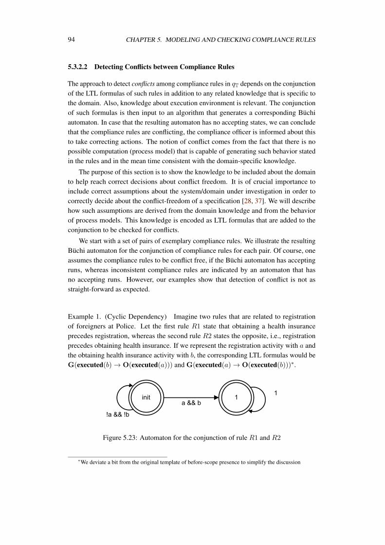
94 CHAPTER 5. MODELING AND CHECKING COMPLIANCE RULES
5.3.2.2 Detecting Conflicts between Compliance Rules
The approach to detect conflicts among compliance rules in qT depends on the conjunctionof the LTL formulas of such rules in addition to any related knowledge that is specific tothe domain. Also, knowledge about execution environment is relevant. The conjunctionof such formulas is then input to an algorithm that generates a corresponding Büchiautomaton. In case that the resulting automaton has no accepting states, we can concludethat the compliance rules are conflicting, the compliance officer is informed about thisto take correcting actions. The notion of conflict comes from the fact that there is nopossible computation (process model) that is capable of generating such behavior statedin the rules and in the mean time consistent with the domain-specific knowledge.
The purpose of this section is to show the knowledge to be included about the domainto help reach correct decisions about conflict freedom. It is of crucial importance toinclude correct assumptions about the system/domain under investigation in order tocorrectly decide about the conflict-freedom of a specification [28, 37]. We will describehow such assumptions are derived from the domain knowledge and from the behaviorof process models. This knowledge is encoded as LTL formulas that are added to theconjunction to be checked for conflicts.
We start with a set of pairs of exemplary compliance rules. We illustrate the resultingBüchi automaton for the conjunction of compliance rules for each pair. Of course, oneassumes the compliance rules to be conflict free, if the Büchi automaton has acceptingruns, whereas inconsistent compliance rules are indicated by an automaton that hasno accepting runs. However, our examples show that detection of conflict is not asstraight-forward as expected.
Example 1. (Cyclic Dependency) Imagine two rules that are related to registrationof foreigners at Police. Let the first rule R1 state that obtaining a health insuranceprecedes registration, whereas the second rule R2 states the opposite, i.e., registrationprecedes obtaining health insurance. If we represent the registration activity with a andthe obtaining health insurance activity with b, the corresponding LTL formulas would beG(executed(b) → O(executed(a))) and G(executed(a) → O(executed(b)))∗.
Figure 5.23: Automaton for the conjunction of rule R1 and R2
∗We deviate a bit from the original template of before-scope presence to simplify the discussion
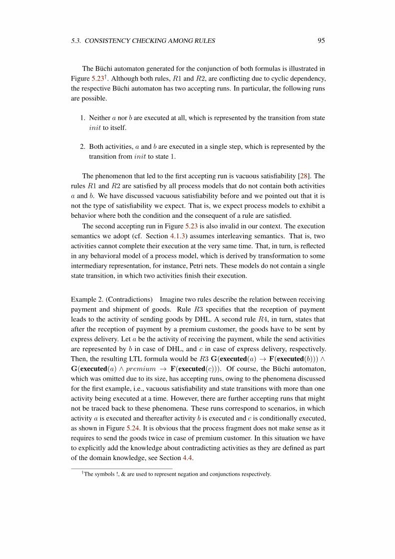
5.3. CONSISTENCY CHECKING AMONG RULES 95
The Büchi automaton generated for the conjunction of both formulas is illustrated inFigure 5.23†. Although both rules, R1 and R2, are conflicting due to cyclic dependency,the respective Büchi automaton has two accepting runs. In particular, the following runsare possible.
1. Neither a nor b are executed at all, which is represented by the transition from stateinit to itself.
2. Both activities, a and b are executed in a single step, which is represented by thetransition from init to state 1.
The phenomenon that led to the first accepting run is vacuous satisfiability [28]. Therules R1 and R2 are satisfied by all process models that do not contain both activitiesa and b. We have discussed vacuous satisfiability before and we pointed out that it isnot the type of satisfiability we expect. That is, we expect process models to exhibit abehavior where both the condition and the consequent of a rule are satisfied.
The second accepting run in Figure 5.23 is also invalid in our context. The executionsemantics we adopt (cf. Section 4.1.3) assumes interleaving semantics. That is, twoactivities cannot complete their execution at the very same time. That, in turn, is reflectedin any behavioral model of a process model, which is derived by transformation to someintermediary representation, for instance, Petri nets. These models do not contain a singlestate transition, in which two activities finish their execution.
Example 2. (Contradictions) Imagine two rules describe the relation between receivingpayment and shipment of goods. Rule R3 specifies that the reception of paymentleads to the activity of sending goods by DHL. A second rule R4, in turn, states thatafter the reception of payment by a premium customer, the goods have to be sent byexpress delivery. Let a be the activity of receiving the payment, while the send activitiesare represented by b in case of DHL, and c in case of express delivery, respectively.Then, the resulting LTL formula would be R3 G(executed(a) → F(executed(b))) ∧G(executed(a) ∧ premium → F(executed(c))). Of course, the Büchi automaton,which was omitted due to its size, has accepting runs, owing to the phenomena discussedfor the first example, i.e., vacuous satisfiability and state transitions with more than oneactivity being executed at a time. However, there are further accepting runs that mightnot be traced back to these phenomena. These runs correspond to scenarios, in whichactivity a is executed and thereafter activity b is executed and c is conditionally executed,as shown in Figure 5.24. It is obvious that the process fragment does not make sense as itrequires to send the goods twice in case of premium customer. In this situation we haveto explicitly add the knowledge about contradicting activities as they are defined as partof the domain knowledge, see Section 4.4.
†The symbols !, & are used to represent negation and conjunctions respectively.
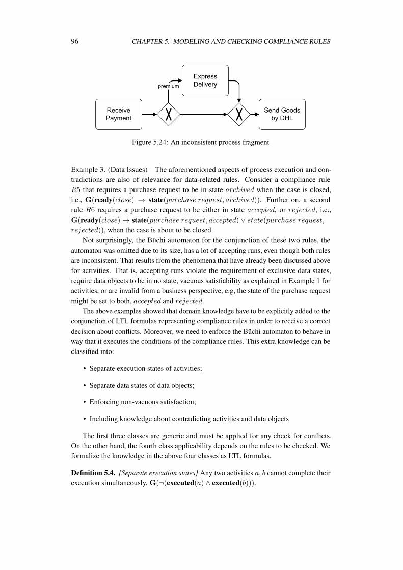
96 CHAPTER 5. MODELING AND CHECKING COMPLIANCE RULES
Figure 5.24: An inconsistent process fragment
Example 3. (Data Issues) The aforementioned aspects of process execution and con-tradictions are also of relevance for data-related rules. Consider a compliance ruleR5 that requires a purchase request to be in state archived when the case is closed,i.e., G(ready(close) → state(purchase request, archived)). Further on, a secondrule R6 requires a purchase request to be either in state accepted, or rejected, i.e.,G(ready(close) → state(purchase request, accepted) ∨ state(purchase request,
rejected)), when the case is about to be closed.Not surprisingly, the Büchi automaton for the conjunction of these two rules, the
automaton was omitted due to its size, has a lot of accepting runs, even though both rulesare inconsistent. That results from the phenomena that have already been discussed abovefor activities. That is, accepting runs violate the requirement of exclusive data states,require data objects to be in no state, vacuous satisfiability as explained in Example 1 foractivities, or are invalid from a business perspective, e.g, the state of the purchase requestmight be set to both, accepted and rejected.
The above examples showed that domain knowledge have to be explicitly added to theconjunction of LTL formulas representing compliance rules in order to receive a correctdecision about conflicts. Moreover, we need to enforce the Büchi automaton to behave inway that it executes the conditions of the compliance rules. This extra knowledge can beclassified into:
• Separate execution states of activities;
• Separate data states of data objects;
• Enforcing non-vacuous satisfaction;
• Including knowledge about contradicting activities and data objects
The first three classes are generic and must be applied for any check for conflicts.On the other hand, the fourth class applicability depends on the rules to be checked. Weformalize the knowledge in the above four classes as LTL formulas.
Definition 5.4. [Separate execution states] Any two activities a, b cannot complete theirexecution simultaneously, G(¬(executed(a) ∧ executed(b))).
5.3. CONSISTENCY CHECKING AMONG RULES 97
Definition 5.5 formalizes the nature of interleaving execution by not allowing a statewhere any two activities a and b can complete their execution. This can be applied also tothe case of data object states, where a data object can assume only value at a time.
Definition 5.5. [Separate data object states] For any data object d having a finite setof states Sd, d can assume exactly one state at a time ∀s ∈ Sd : G(state(d, s) →
s′∈Sd\s ¬state(d, s′))
To enforce non-vacuous satisfaction, for each compliance rule on the form p → q weenforce the execution of p by adding F(p) to the conjunction.
Definition 5.6. [Non Vacuous Satisfiability] A compliance rule r has to be non-vacuouslysatisfied by adding F(a) to the conjunction to be checked if and only if a appears in thecondition of r.
To reflect contradictions between activities, as can be derived from the domainknowledge, we add an LTL formula that insures that the execution of one activity a cannever be followed by the execution of any of its contradicting activities.
Definition 5.7. [Contradicting Activities] If two activities a and b are known to be con-tradicting, exclusive, from the domain knowledge, this is reflected as G(executed(a) →G(¬executed(b))).
The LTL formula from Definition 5.7 is added to the conjunction for each activity a
that appears in the compliance rules and all of its contradicting activities as defined in thedomain knowledge.
Theorem 5.2. A set of activity execution ordering compliance rules R are consistentunder the domain knowledge rules D, where elements of both sets are LTL formulas, ifand only if the Büchi automaton generated for their conjunction has at least one acceptingrun.
Proof. If the generated Büchi automaton has an accepting run then there is a computation,sequence of execution, in which the formulas are satisfied. On the other hand, lack ofany accepting runs implies the impossibility of finding a computation that satisfies theconjunction of formulas.
Theorem 5.2 implies that the decision about conflict freedom is bound to the availabil-ity of sufficient domain knowledge. That is, for instance, if we lack the knowledge aboutcontradiction between two activities, we can decide conflict freedom of two rules thatrequire them to execute non-exclusively. Still, the approach of utilizing Büchi automatamay help construct the domain knowledge. This could be achieved by synthesizingprocess fragments out of the Büchi automaton and negotiating whether it is acceptablewith domain experts and business analysts. At that point, domain experts are able toidentify conflicts and the domain knowledge must be updated. The synthesis of processfragments is out of scope of the thesis.
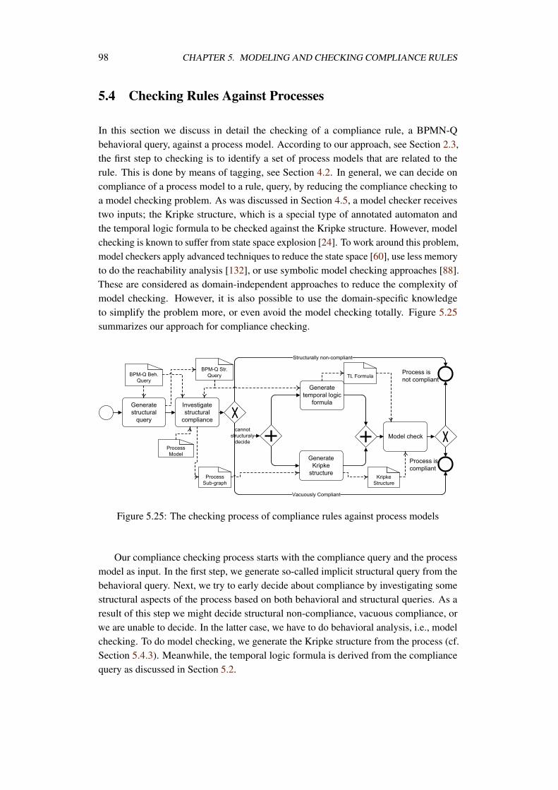
98 CHAPTER 5. MODELING AND CHECKING COMPLIANCE RULES
5.4 Checking Rules Against Processes
In this section we discuss in detail the checking of a compliance rule, a BPMN-Qbehavioral query, against a process model. According to our approach, see Section 2.3,the first step to checking is to identify a set of process models that are related to therule. This is done by means of tagging, see Section 4.2. In general, we can decide oncompliance of a process model to a rule, query, by reducing the compliance checking toa model checking problem. As was discussed in Section 4.5, a model checker receivestwo inputs; the Kripke structure, which is a special type of annotated automaton andthe temporal logic formula to be checked against the Kripke structure. However, modelchecking is known to suffer from state space explosion [24]. To work around this problem,model checkers apply advanced techniques to reduce the state space [60], use less memoryto do the reachability analysis [132], or use symbolic model checking approaches [88].These are considered as domain-independent approaches to reduce the complexity ofmodel checking. However, it is also possible to use the domain-specific knowledgeto simplify the problem more, or even avoid the model checking totally. Figure 5.25summarizes our approach for compliance checking.
Figure 5.25: The checking process of compliance rules against process models
Our compliance checking process starts with the compliance query and the processmodel as input. In the first step, we generate so-called implicit structural query from thebehavioral query. Next, we try to early decide about compliance by investigating somestructural aspects of the process based on both behavioral and structural queries. As aresult of this step we might decide structural non-compliance, vacuous compliance, orwe are unable to decide. In the latter case, we have to do behavioral analysis, i.e., modelchecking. To do model checking, we generate the Kripke structure from the process (cf.Section 5.4.3). Meanwhile, the temporal logic formula is derived from the compliancequery as discussed in Section 5.2.
5.4. CHECKING RULES AGAINST PROCESSES 99
5.4.1 Implicit Structural Queries
A behavioral BPMN-Q query contains two pieces of information. Firstly, it contains astructural query, the nodes and edges. This structural query will be used to check whetherwe can structurally decide about compliance, non-compliance. Secondly, it contains thetemporal logic formula that would be model checked against the process. We showed howbehavioral queries map to temporal logic formulas in Section 5.2. Also, we discussed inSection 4.2 how a structural query is matched to a process model. Here, we need to showthat obtaining a structural query from a behavioral query is not straightforward.
All compliance rules discussed earlier describe ordering between nodes in a process.For instance, global-scope presence requires that certain activity has to occur somewhereafter the start of the process. Thus, finding a path , sequence of nodes, between the sourceand target nodes provides the first step to check for compliance, by considering executionsemantics of those nodes in between. This means, if we cannot find any paths betweenthe source and target nodes, we can structurally decide about non compliance, since noexecution ordering is guaranteed.
To obtain a structural query from a well formed behavioral one, we use the same set ofnodes as in the behavioral query. All paths specified in the behavioral query are mapped tosimilar structural paths, i.e., without the behavioral stereotypes. If a path in the behavioralquery has an exclude property, this is neglected in the structural counterpart. Similarly,behavioral data flow edges are dropped since they cannot be decided structurally.
5.4.2 Structural Investigation about Compliance
Up to this point, we have three pieces of information in hand, the process model, thebehavioral query, and the implicit structural queries. In this step we want to run structuralinvestigations to see whether we can early decide about compliance.
Depending on the rule r, we can decide on the compliance of a process model p to r.For instance, the case of global-presence, see Section 5.2.3.1, a process p can be judgedas structurally non-compliant if it lacks any occurrence of the activity a specified in r.Conversely, is the case of global-absence.
Another example is the after-scope presence pattern, cf. Section 5.2.3.5. Consider rto be G(executed(a) → F(executed(b)). In this case a process model p is structurallynon-compliant if it has an occurrence of a and:
• It has no occurrence of b, or,
• It has an occurrence of b but with no execution path from a to b
Such structural investigations can be done efficiently. Checking of activity occur-rences can be done in linear time to the number of activities in a process. Checkingexecution paths can be achieved by matching the structural query to the process. This isachieved also in a low polynomial time. We can decide about non-compliance due to lackof execution paths if the matching returns an empty sub-graph. If the matching sub-graph
100 CHAPTER 5. MODELING AND CHECKING COMPLIANCE RULES
is not empty, we cannot structurally decide about compliance and model checking has totake place.
Definition 5.8. [Structural non-compliance] A process modelP = (A, E ,D,G,S,DataState, CF ,DF , CFC, ID) is structurally non compliant to aBPMN-Q behavioral queryQ = (AQ, EQ,DQ,SQ,DataStateQ,PQ,DFQ, isAnonymous,X , T YPE) if:
• ∃(x, y) ∈ PQ : T YPE((x, y)) = leadsto ∧ isAnonymous(y) = false @z ∈(A ∪ E) : label(y) = label(z). No occurrences of target nodes for the leads topaths in the investigated process,
• ∃(x, y) ∈ PQ∧T YPE((x, y)) = precedes ∧isAnonymous(x) = false ∃z ∈(A ∪ E) : label(x) = label(z). No occurrences of source nodes for the precedespaths in the investigated process,
• The implied structural query has no matches within the process.
Another interesting issue is the ability to decide about vacuous compliance. Anexample situation for vacuous compliance is the rule r above. A process model pvacuously satisfies this rule if it lacks any occurrence of activity a. Reporting vacuouscompliance may be important for experts so that they update their rules or have furtherinvestigations about the process [28]. Of course, vacuous compliance can be detected viamodel checkers. However, this calls for generating specific vacuity compliance testingformulas, which will be discussed later.
Definition 5.9. [Structural vacuous compliance] A process modelP = (A, E ,D,G,S,DataState, CF ,DF , CFC, ID) is structurally vacuous compliantto a BPMN-Q behavioral queryQ = (AQ, EQ,DQ,SQ,DataStateQ,PQ,DFQ, isAnonymous,X , T YPE) if:
• ∀(x, y) ∈ PQ : T YPE((x, y)) = leadsto ∧ isAnonymous(y) = false @z ∈(A ∪ E) : label(x) = label(z). No occurrences of source nodes for the leads topaths in the investigated process model,
• ∀(x, y) ∈ PQ : T YPE((x, y)) = precedes ∧ isAnonymous(y) = false @z ∈(A ∪ E) : label(y) = label(z). No occurrences of target nodes for the precedespaths in the investigated process model.
5.4.3 Model Checking Rules
When it is not possible to structurally decide about compliance/non-compliance, wehave to do an exhaustive state space analysis, i.e., model checking. As was discussed inSection 4.5, we need two inputs; the temporal logic formula to be checked, the compliancerule in our case, and the system to check, the process model.
5.4. CHECKING RULES AGAINST PROCESSES 101
In Section 5.2 we showed how to obtain for each compliance rule, pattern, an equiv-alent temporal logic formula. In this section, we describe how to derive the Kripkestructure, cf. Definition 4.11, from process models.
In Section 4.1.3.3, we discussed how to derive a Petri net from a well-formed processmodel. In this section we build on that and show how to derive a Kripke structureM = (S, si, R, L) from the reachability graph of a Petri net.
Definition 5.10. [Reachability Graph] The reachability graph of a Petri net PN =
[P, T, F,m0] is a tuple RG = (V, TR, v0) where V is the set of states, markings. TR ⊆V × V is the transition relation between states, caused by firing transitions in T . v0 isthe initial state of RG which is equal to m0.
The Petri net PN = [P, T, F,m0] obtained from a process modelP = (A, E ,D,G,S,DataState, CF ,DF , CFC, ID) according to Definition 4.4 al-ready determines the initial marking of the net. Thus, we can compute the reachabilitygraph RG of the net using the firing of transitions [113]. Each time a transition fires,the state of the net changes, the marking of places. For our case we are interested inthe marking of three different types of places. Firstly, data places which correspondto the data value(state) assumed by a data object. In Section 4.1.3.2 we showed that adata object is mapped to a set of places corresponding to its set of states. Thus, eachtime a data place, say dob1_state3, contains a token; the predicate state(dob1, state3)holds. The other two types of places correspond to control flow. Since any activity isassigned exactly one input control flow place and one output control flow place, we candetermine whether an activity a is ready,ready(a), or executed, executed(a), in any Petrinet marking mj if pi ∈ •ta ∧mj(pi) > 0 or po ∈ •ta ∧mj(po) > 0 respectively.
The proposition start holds in the initial marking where the input place for thetransition ts, corresponding to the start event of the process, has a token. Similarly, theproposition end holds when the output place of transition te, corresponding to the endevent of the process, has a token, indicating the termination of execution.
The set of atomic propositions AP is constructed as follows
Definition 5.11. [Atomic propositions for compliance checking] The set of atomic propo-sitions AP is constructed from a process modelP = (A, E ,D,G,S,DataState, CF ,DF , CFC, ID) as follows: AP = ready_a :
a ∈ A ∪ executed_a : a ∈ A ∪ state_d_s : (d, s) ∈ DataState∪start, end
Definition 5.12. [Generating Kripke structure from process models] A Kripke structureM = (S, si, R, L) can be obtained from the reachability graph RG = (V, TR, v0) of aPetri net PN = [P, T, F,m0] generated from a processP = (A, E ,D,G,S,DataState, CF ,DF , CFC, ID) with respect to a set of atomicpropositions AP as follows:
• S = V ,
102 CHAPTER 5. MODELING AND CHECKING COMPLIANCE RULES
• si = v0,
• R = TR ∪ (v, v) : v ∈ V ∧ @r ∈ V : (v, r) ∈ TR,
• ∀s ∈ S :
– start ∈ L(s) if and only if s = si. The start proposition holds in the initialstate of the execution,
– end ∈ L(s) if and only if @(s, _) ∈ TR. The end proposition holds for statesin the reachability graph with no outgoing edges to other states,
– ready_a ∈ L(s) if and only if ms(p(_,a)) = 1 ∧ p(_,a) ∈ •ta where a ∈ A.The ready proposition holds in state s for each Petri net transition, representinga process activity, having its input control flow place marked,
– executed_a ∈ L(s) if and only if ms(p(a,_)) = 1 ∧ p(_,a) ∈ ta• where
a ∈ A. The executed proposition holds in state s for each Petri net transition,representing a process activity, having its output control flow place marked,
– state(data, state) ∈ L(s) if and only if ms(p(data,state)) = 1 where(data, state) ∈ DataState. The proposition state(data, value) holds ineach execution state s where its corresponding place is marked.
After obtaining the Kripke structure, the compliance rule can be model checkedagainst it. Also, we can run a vacuous compliance test. In Section 5.4.2, we discussedhow vacuous compliance can be checked on the structure of the business process, cfDefinition 5.9. However, when it comes to data and conditional compliance rules, it mightnot be possible to decide vacuous compliance on a process structure. Thus, we need torun this check against the Kripke structure obtained from the process model.
A vacuous compliance check simply tests whether a compliance rule’s condition willever be enabled during the execution of a process. That is, we need to find at least oneexecution state in which the condition part of the rule will be true. For instance, if we takea conditional after-scope presence rule on the form AG(state(d1, s1) ∧ state(d2, s3) →AF(executed(act1))), a vacuous compliance check would be EF(state(d1, s1) ∧state(d2, s3)). We can notice that CTL not LTL is capable of expressing vacuouscompliance checking due to its support to existential quantifiers over execution paths.
From a processing cost point of view, the checking for vacuous compliance is,theoretically, much cheaper than checking the rule itself, due to its existential nature.Thus, once a vacuous compliance checking fails, we do not need to check the originalrule itself as we know it is vacuously satisfied.
5.5 Example
This section introduces a process model along with a set of compliance requirementsrelated to this process model in order to illustrate the applicability of our approach. We
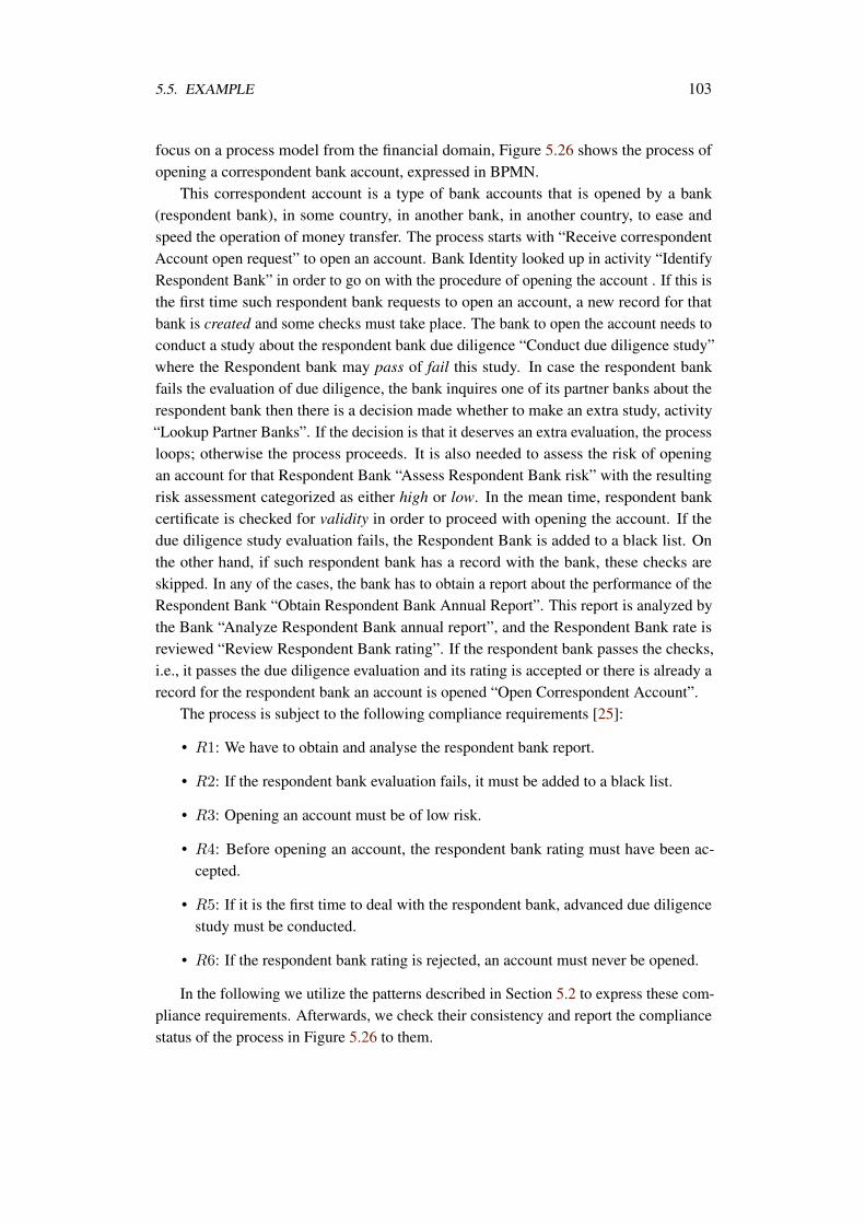
5.5. EXAMPLE 103
focus on a process model from the financial domain, Figure 5.26 shows the process ofopening a correspondent bank account, expressed in BPMN.
This correspondent account is a type of bank accounts that is opened by a bank(respondent bank), in some country, in another bank, in another country, to ease andspeed the operation of money transfer. The process starts with “Receive correspondentAccount open request” to open an account. Bank Identity looked up in activity “IdentifyRespondent Bank” in order to go on with the procedure of opening the account . If this isthe first time such respondent bank requests to open an account, a new record for thatbank is created and some checks must take place. The bank to open the account needs toconduct a study about the respondent bank due diligence “Conduct due diligence study”where the Respondent bank may pass of fail this study. In case the respondent bankfails the evaluation of due diligence, the bank inquires one of its partner banks about therespondent bank then there is a decision made whether to make an extra study, activity“Lookup Partner Banks”. If the decision is that it deserves an extra evaluation, the processloops; otherwise the process proceeds. It is also needed to assess the risk of openingan account for that Respondent Bank “Assess Respondent Bank risk” with the resultingrisk assessment categorized as either high or low. In the mean time, respondent bankcertificate is checked for validity in order to proceed with opening the account. If thedue diligence study evaluation fails, the Respondent Bank is added to a black list. Onthe other hand, if such respondent bank has a record with the bank, these checks areskipped. In any of the cases, the bank has to obtain a report about the performance of theRespondent Bank “Obtain Respondent Bank Annual Report”. This report is analyzed bythe Bank “Analyze Respondent Bank annual report”, and the Respondent Bank rate isreviewed “Review Respondent Bank rating”. If the respondent bank passes the checks,i.e., it passes the due diligence evaluation and its rating is accepted or there is already arecord for the respondent bank an account is opened “Open Correspondent Account”.
The process is subject to the following compliance requirements [25]:
• R1: We have to obtain and analyse the respondent bank report.
• R2: If the respondent bank evaluation fails, it must be added to a black list.
• R3: Opening an account must be of low risk.
• R4: Before opening an account, the respondent bank rating must have been ac-cepted.
• R5: If it is the first time to deal with the respondent bank, advanced due diligencestudy must be conducted.
• R6: If the respondent bank rating is rejected, an account must never be opened.
In the following we utilize the patterns described in Section 5.2 to express these com-pliance requirements. Afterwards, we check their consistency and report the compliancestatus of the process in Figure 5.26 to them.
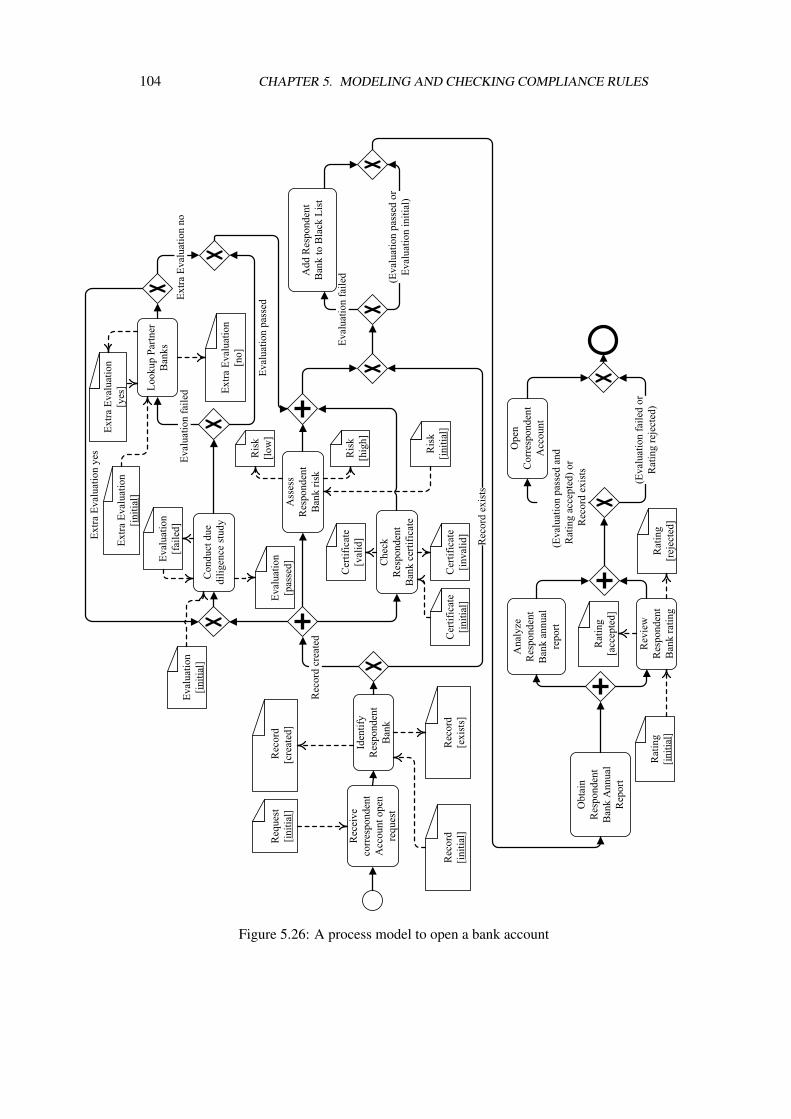
104 CHAPTER 5. MODELING AND CHECKING COMPLIANCE RULES
Figure 5.26: A process model to open a bank account
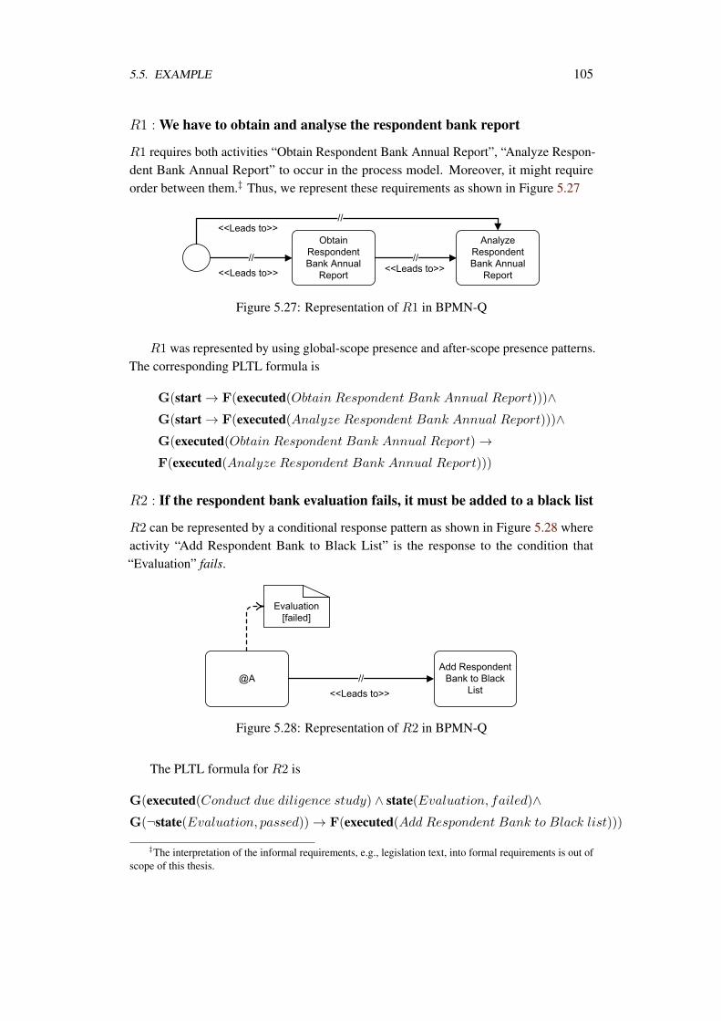
5.5. EXAMPLE 105
R1 : We have to obtain and analyse the respondent bank report
R1 requires both activities “Obtain Respondent Bank Annual Report”, “Analyze Respon-dent Bank Annual Report” to occur in the process model. Moreover, it might requireorder between them.‡ Thus, we represent these requirements as shown in Figure 5.27
Figure 5.27: Representation of R1 in BPMN-Q
R1 was represented by using global-scope presence and after-scope presence patterns.The corresponding PLTL formula is
G(start → F(executed(Obtain Respondent Bank Annual Report)))∧G(start → F(executed(Analyze Respondent Bank Annual Report)))∧G(executed(Obtain Respondent Bank Annual Report) →F(executed(Analyze Respondent Bank Annual Report)))
R2 : If the respondent bank evaluation fails, it must be added to a black list
R2 can be represented by a conditional response pattern as shown in Figure 5.28 whereactivity “Add Respondent Bank to Black List” is the response to the condition that“Evaluation” fails.
Figure 5.28: Representation of R2 in BPMN-Q
The PLTL formula for R2 is
G(executed(Conduct due diligence study) ∧ state(Evaluation, failed)∧G(¬state(Evaluation, passed)) → F(executed(Add Respondent Bank to Black list)))
‡The interpretation of the informal requirements, e.g., legislation text, into formal requirements is out ofscope of this thesis.
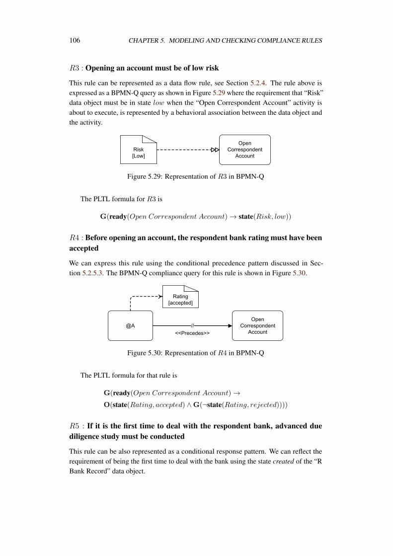
106 CHAPTER 5. MODELING AND CHECKING COMPLIANCE RULES
R3 : Opening an account must be of low risk
This rule can be represented as a data flow rule, see Section 5.2.4. The rule above isexpressed as a BPMN-Q query as shown in Figure 5.29 where the requirement that “Risk”data object must be in state low when the “Open Correspondent Account” activity isabout to execute, is represented by a behavioral association between the data object andthe activity.
Figure 5.29: Representation of R3 in BPMN-Q
The PLTL formula for R3 is
G(ready(Open Correspondent Account) → state(Risk, low))
R4 : Before opening an account, the respondent bank rating must have beenaccepted
We can express this rule using the conditional precedence pattern discussed in Sec-tion 5.2.5.3. The BPMN-Q compliance query for this rule is shown in Figure 5.30.
Figure 5.30: Representation of R4 in BPMN-Q
The PLTL formula for that rule is
G(ready(Open Correspondent Account) →O(state(Rating, accepted) ∧G(¬state(Rating, rejected))))
R5 : If it is the first time to deal with the respondent bank, advanced duediligence study must be conducted
This rule can be also represented as a conditional response pattern. We can reflect therequirement of being the first time to deal with the bank using the state created of the “RBank Record” data object.
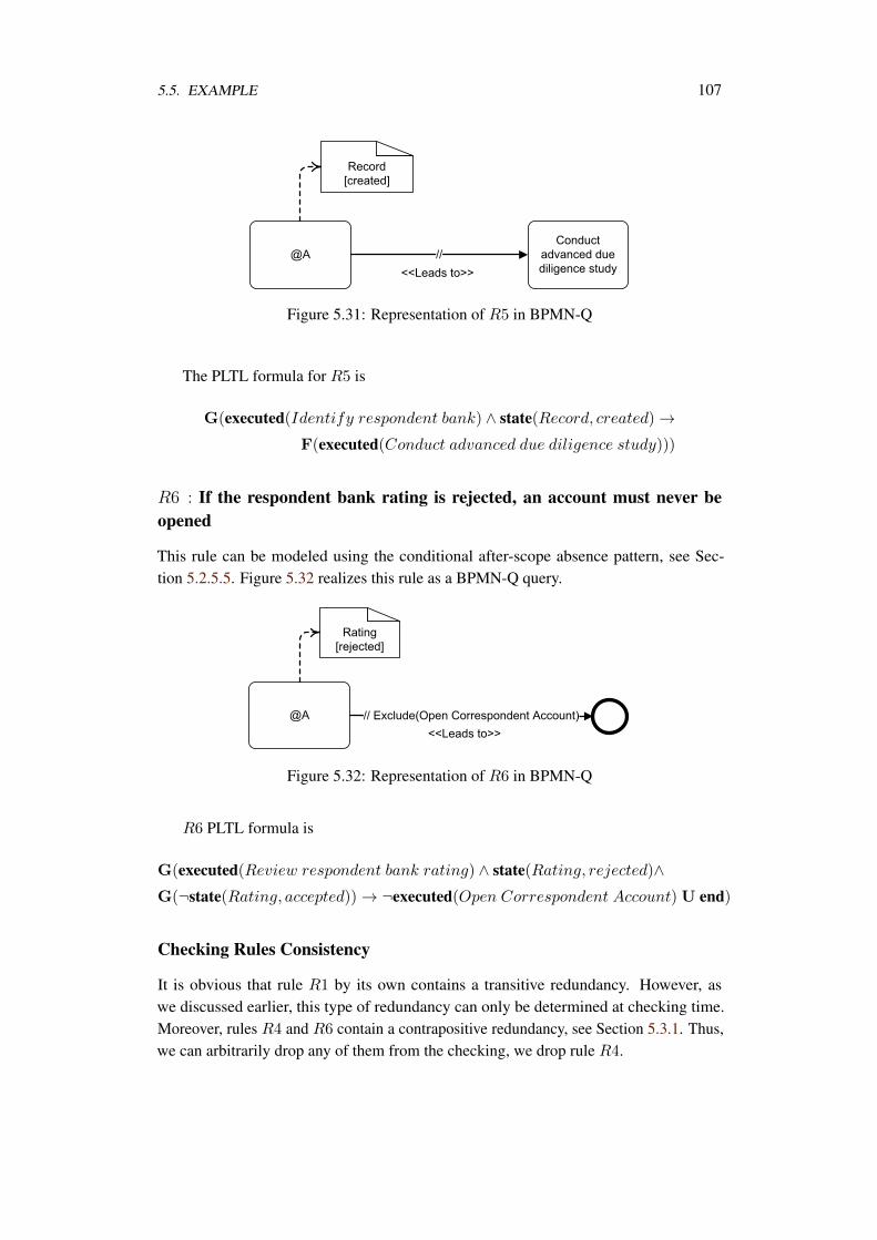
5.5. EXAMPLE 107
Figure 5.31: Representation of R5 in BPMN-Q
The PLTL formula for R5 is
G(executed(Identify respondent bank) ∧ state(Record, created) →F(executed(Conduct advanced due diligence study)))
R6 : If the respondent bank rating is rejected, an account must never beopened
This rule can be modeled using the conditional after-scope absence pattern, see Sec-tion 5.2.5.5. Figure 5.32 realizes this rule as a BPMN-Q query.
Figure 5.32: Representation of R6 in BPMN-Q
R6 PLTL formula is
G(executed(Review respondent bank rating) ∧ state(Rating, rejected)∧G(¬state(Rating, accepted)) → ¬executed(Open Correspondent Account) U end)
Checking Rules Consistency
It is obvious that rule R1 by its own contains a transitive redundancy. However, aswe discussed earlier, this type of redundancy can only be determined at checking time.Moreover, rules R4 and R6 contain a contrapositive redundancy, see Section 5.3.1. Thus,we can arbitrarily drop any of them from the checking, we drop rule R4.
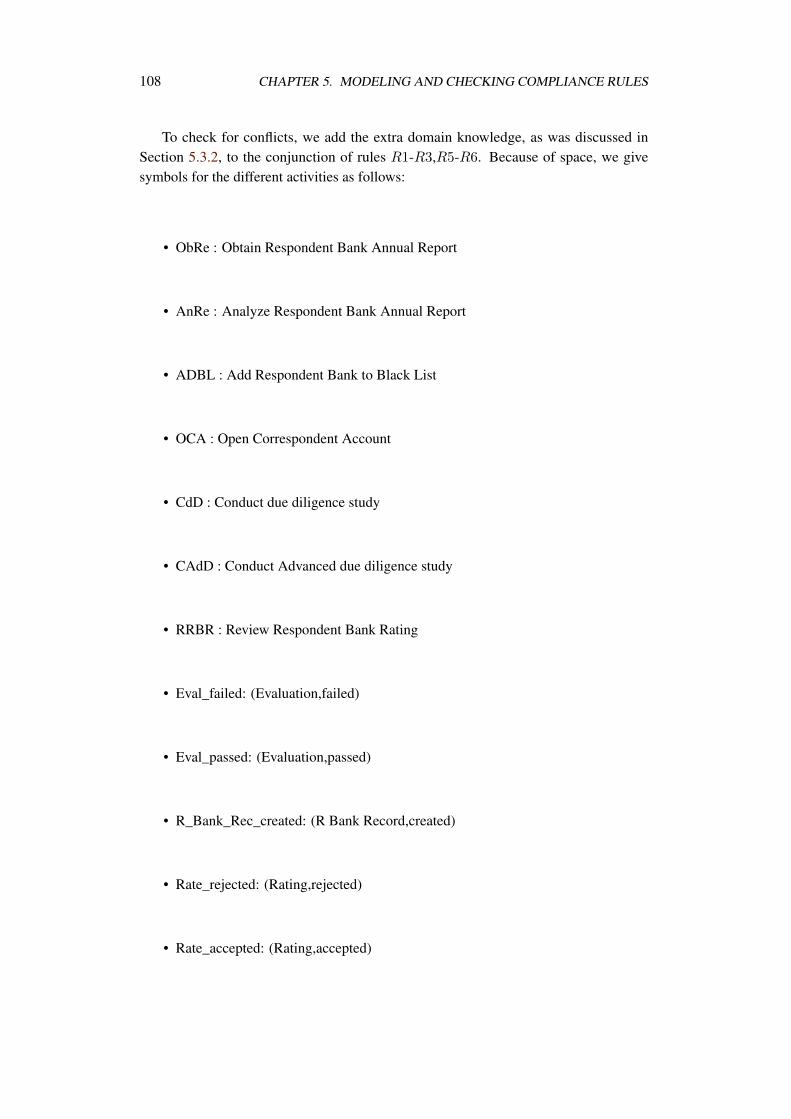
108 CHAPTER 5. MODELING AND CHECKING COMPLIANCE RULES
To check for conflicts, we add the extra domain knowledge, as was discussed inSection 5.3.2, to the conjunction of rules R1-R3,R5-R6. Because of space, we givesymbols for the different activities as follows:
• ObRe : Obtain Respondent Bank Annual Report
• AnRe : Analyze Respondent Bank Annual Report
• ADBL : Add Respondent Bank to Black List
• OCA : Open Correspondent Account
• CdD : Conduct due diligence study
• CAdD : Conduct Advanced due diligence study
• RRBR : Review Respondent Bank Rating
• Eval_failed: (Evaluation,failed)
• Eval_passed: (Evaluation,passed)
• R_Bank_Rec_created: (R Bank Record,created)
• Rate_rejected: (Rating,rejected)
• Rate_accepted: (Rating,accepted)
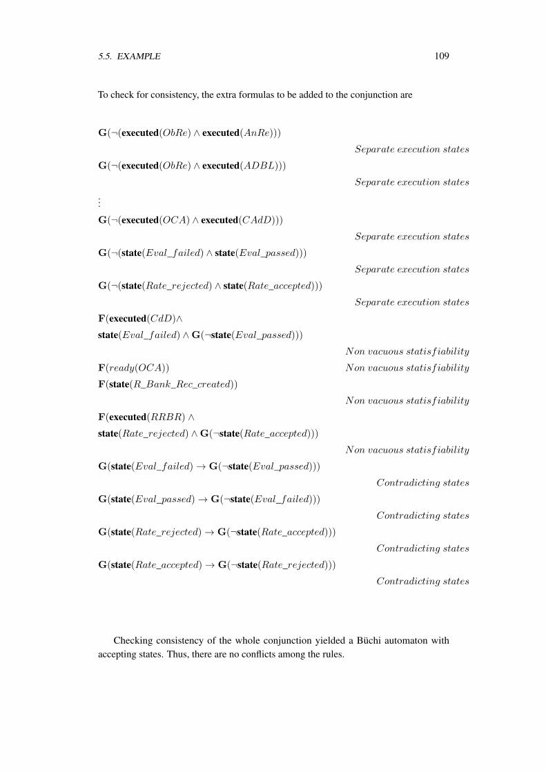
5.5. EXAMPLE 109
To check for consistency, the extra formulas to be added to the conjunction are
G(¬(executed(ObRe) ∧ executed(AnRe)))
Separate execution states
G(¬(executed(ObRe) ∧ executed(ADBL)))
Separate execution states
...
G(¬(executed(OCA) ∧ executed(CAdD)))
Separate execution states
G(¬(state(Eval_failed) ∧ state(Eval_passed)))
Separate execution states
G(¬(state(Rate_rejected) ∧ state(Rate_accepted)))
Separate execution states
F(executed(CdD)∧state(Eval_failed) ∧G(¬state(Eval_passed)))
Non vacuous statisfiability
F(ready(OCA)) Non vacuous statisfiability
F(state(R_Bank_Rec_created))
Non vacuous statisfiability
F(executed(RRBR) ∧state(Rate_rejected) ∧G(¬state(Rate_accepted)))
Non vacuous statisfiability
G(state(Eval_failed) → G(¬state(Eval_passed)))
Contradicting states
G(state(Eval_passed) → G(¬state(Eval_failed)))
Contradicting states
G(state(Rate_rejected) → G(¬state(Rate_accepted)))
Contradicting states
G(state(Rate_accepted) → G(¬state(Rate_rejected)))
Contradicting states
Checking consistency of the whole conjunction yielded a Büchi automaton withaccepting states. Thus, there are no conflicts among the rules.
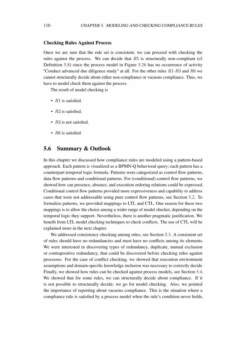
110 CHAPTER 5. MODELING AND CHECKING COMPLIANCE RULES
Checking Rules Against Process
Once we are sure that the rule set is consistent, we can proceed with checking therules against the process. We can decide that R5 is structurally non-compliant (cf.Definition 5.8) since the process model in Figure 5.26 has no occurrence of activity“Conduct advanced due diligence study“ at all. For the other rules R1-R3 and R6 wecannot structurally decide about either non-compliance or vacuous compliance. Thus, wehave to model check them against the process.
The result of model checking is
• R1 is satisfied.
• R2 is satisfied.
• R3 is not satisfied.
• R6 is satisfied.
5.6 Summary & Outlook
In this chapter we discussed how compliance rules are modeled using a pattern-basedapproach. Each pattern is visualized as a BPMN-Q behavioral query; each pattern has acounterpart temporal logic formula. Patterns were categorized as control flow patterns,data flow patterns and conditional patterns. For (conditional) control flow patterns, weshowed how can presence, absence, and execution ordering relations could be expressed.Conditional control flow patterns provided more expressiveness and capability to addresscases that were not addressable using pure control flow patterns, see Section 5.2. Toformalize patterns, we provided mappings to LTL and CTL. One reason for these twomappings is to allow the choice among a wider range of model checker, depending on thetemporal logic they support. Nevertheless, there is another pragmatic justification. Webenefit from LTL model checking techniques to check conflicts. The use of CTL will beexplained more in the next chapter.
We addressed consistency checking among rules, see Section 5.3. A consistent setof rules should have no redundancies and must have no conflicts among its elements.We were interested in discovering types of redundancy, duplicate, mutual exclusionor contrapositive redundancy, that could be discovered before checking rules againstprocesses. For the case of conflict checking, we showed that execution environmentassumptions and domain-specific knowledge inclusion was necessary to correctly decide.Finally, we showed how rules can be checked against process models, see Section 5.4.We showed that for some rules, we can structurally decide about compliance. If itis not possible to structurally decide; we go for model checking. Also, we pointedthe importance of reporting about vacuous compliance. This is the situation where acompliance rule is satisfied by a process model when the rule’s condition never holds.

5.6. SUMMARY & OUTLOOK 111
In Section 5.5, we had a case study where we modeled and checked a set of anti moneylaundering compliance rules.
In the next chapter, we will describe an approach to provide useful feedback, explana-tion, to the user in case a process model violates rule(s).

Chapter 6
Explaining Compliance RulesViolations
So far, compliance rules addressing control and data flow aspects of process models havebeen modeled and verified. In general, when a property is not satisfied by the system underinvestigation, the model checker generates a counterexample. Such a counterexample is asequence of states which shows how the property was violated.
This is another interesting question; how can we explain violations to the user? Astarting point could be using the counterexample generated from the model checker(cf. [38]). The drawbacks of such an approach are manifold. Firstly, the generated coun-terexamples are given in terms of transitions, i.e., the sequence of states in the investigatedfinite state machine. This endures a cost of re-translating such traces backwards intothe structure of process models, it might not always be possible to generate meaningfulrepresentation that the user can easily understand, e.g., the handling of parallel threads.Secondly, the generated counterexample is not exhaustive, i.e., not every possible vio-lation is detected by the model checker. Rather, only the first met violation is reported.Thirdly, the translation will be dependent on both the output of the model checker aswell as the visual notation the user understands. Each time the model checker software ischanged; the translation component has to be adapted. Finally, in the previous chapter,we showed that we can structurally decide about non-compliance, in this case, there is nocounterexample generated at all.
Our objective in this chapter is to provide the user with a useful feedback in theform of parts of the process model whose execution causes violation to a certain rule.By locating parts of the process whose execution causes the violation, we save userseffort to locate such causes and also avoid the threat of missing an unanticipated violationscenario.
We will show in the rest of this chapter that violating scenarios can be declarativelydescribed as BPMN-Q structural queries. We call queries describing violation scenarios,
113
114 CHAPTER 6. EXPLAINING COMPLIANCE RULES VIOLATIONS
anti-pattern queries. For each compliance pattern we derive anti-pattern query(ies)describing the violation. Based on the pattern, derivation of the anti pattern queries mightexamine process-specific conditions, via temporal logic querying.
We start by describing our approach of deriving anti patterns in Section 6.1. Ex-plaining control flow violations comes in Section 6.2. Explaining violations to dataflow rules is covered in Section 6.3. Section 6.4 covers the explanation of conditionalrules violation. Section 6.5 shows how we can simplify the complexity of evaluating thetemporal logic queries using domain-specific knowledge. Limitations of our approachto explain violations is discussed in Section 6.6. Section 6.7 builds on the example weintroduced in Section 5.5. Finally, Section 6.8 summarizes this chapter and links to thenext chapter.
6.1 Deriving Anti Patterns
The question of how violation occurred needs to be explained to the user in a comprehen-sible way. Our approach to answer such a question depends on analyzing the temporallogic formulas corresponding to the various compliance patterns discussed in Chapter 5.For each pattern, the possible causes of violations are derived by negating the CTLformula of the pattern. For each possible violation scenario a structural BPMN-Q queryis developed. Such queries are called anti pattern queries. The reason of this namingis that these queries represent the unwanted behavior, i.e., behavior that if exposed bythe process the violation occurs . The use of BPMN-Q queries visualizes the violationscenario to the user on a process model level, rather than the underlying transition system,by highlighting parts in the model whose execution causes the violation. Depending onthe type of compliance rules being either control flow, data flow, or conditional rules,the generation of such anti pattern queries might investigate the behavioral model of aprocess, via temporal logic querying.
The generation of anti pattern queries starts only after the process model is known tobe violating the rule. For each anti pattern we provide a CTL formula that formalizes theanti pattern. This anti pattern formula has two roles. First, it guides the design of the antipattern query as it declaratively describes the violation. Second, in some cases, as will bediscussed later, there might be more than one possibility to violate a compliance rule. Insuch cases, we have to model check the separate causes of violation in order to match thecorrect anti pattern query to the process to locate the error.
6.2 Control Flow Rules Violations
6.2.1 Global-scope Violation
The violation to global-scope presence occurs whenever there is a chance not to exe-cute the to-be-present activity. Formally, the violation can be described by negatingFormula 5.2. The negated CTL formula which describes the violation for global-scope
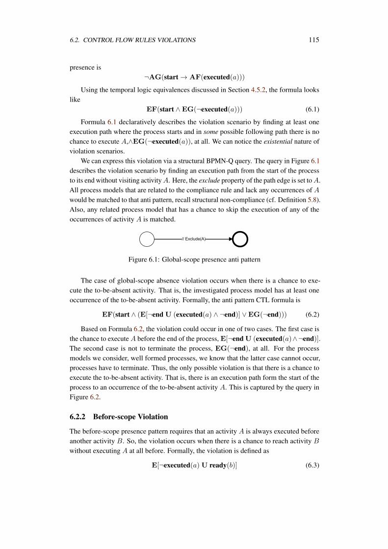
6.2. CONTROL FLOW RULES VIOLATIONS 115
presence is¬AG(start → AF(executed(a)))
Using the temporal logic equivalences discussed in Section 4.5.2, the formula lookslike
EF(start ∧EG(¬executed(a))) (6.1)
Formula 6.1 declaratively describes the violation scenario by finding at least oneexecution path where the process starts and in some possible following path there is nochance to execute A,∧EG(¬executed(a)), at all. We can notice the existential nature ofviolation scenarios.
We can express this violation via a structural BPMN-Q query. The query in Figure 6.1describes the violation scenario by finding an execution path from the start of the processto its end without visiting activity A. Here, the exclude property of the path edge is set to A.All process models that are related to the compliance rule and lack any occurrences of Awould be matched to that anti pattern, recall structural non-compliance (cf. Definition 5.8).Also, any related process model that has a chance to skip the execution of any of theoccurrences of activity A is matched.
Figure 6.1: Global-scope presence anti pattern
The case of global-scope absence violation occurs when there is a chance to exe-cute the to-be-absent activity. That is, the investigated process model has at least oneoccurrence of the to-be-absent activity. Formally, the anti pattern CTL formula is
EF(start ∧ (E[¬end U (executed(a) ∧ ¬end)] ∨EG(¬end))) (6.2)
Based on Formula 6.2, the violation could occur in one of two cases. The first case isthe chance to execute A before the end of the process, E[¬end U (executed(a)∧¬end)].The second case is not to terminate the process, EG(¬end), at all. For the processmodels we consider, well formed processes, we know that the latter case cannot occur,processes have to terminate. Thus, the only possible violation is that there is a chance toexecute the to-be-absent activity. That is, there is an execution path form the start of theprocess to an occurrence of the to-be-absent activity A. This is captured by the query inFigure 6.2.
6.2.2 Before-scope Violation
The before-scope presence pattern requires that an activity A is always executed beforeanother activity B. So, the violation occurs when there is a chance to reach activity B
without executing A at all before. Formally, the violation is defined as
E[¬executed(a) U ready(b)] (6.3)
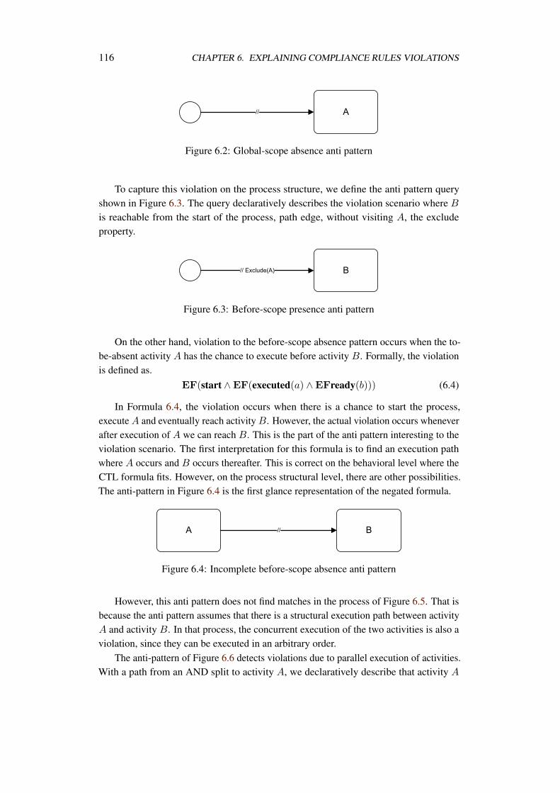
116 CHAPTER 6. EXPLAINING COMPLIANCE RULES VIOLATIONS
Figure 6.2: Global-scope absence anti pattern
To capture this violation on the process structure, we define the anti pattern queryshown in Figure 6.3. The query declaratively describes the violation scenario where B
is reachable from the start of the process, path edge, without visiting A, the excludeproperty.
Figure 6.3: Before-scope presence anti pattern
On the other hand, violation to the before-scope absence pattern occurs when the to-be-absent activity A has the chance to execute before activity B. Formally, the violationis defined as.
EF(start ∧EF(executed(a) ∧EFready(b))) (6.4)
In Formula 6.4, the violation occurs when there is a chance to start the process,execute A and eventually reach activity B. However, the actual violation occurs wheneverafter execution of A we can reach B. This is the part of the anti pattern interesting to theviolation scenario. The first interpretation for this formula is to find an execution pathwhere A occurs and B occurs thereafter. This is correct on the behavioral level where theCTL formula fits. However, on the process structural level, there are other possibilities.The anti-pattern in Figure 6.4 is the first glance representation of the negated formula.
Figure 6.4: Incomplete before-scope absence anti pattern
However, this anti pattern does not find matches in the process of Figure 6.5. That isbecause the anti pattern assumes that there is a structural execution path between activityA and activity B. In that process, the concurrent execution of the two activities is also aviolation, since they can be executed in an arbitrary order.
The anti-pattern of Figure 6.6 detects violations due to parallel execution of activities.With a path from an AND split to activity A, we declaratively describe that activity A
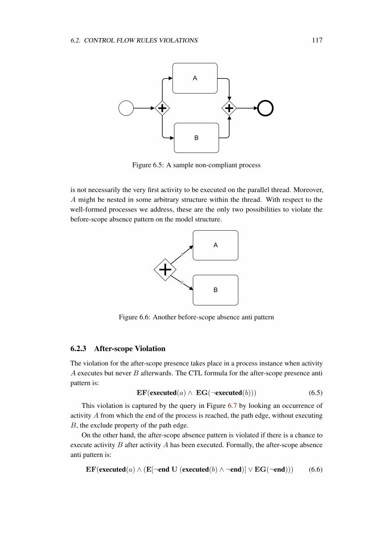
6.2. CONTROL FLOW RULES VIOLATIONS 117
Figure 6.5: A sample non-compliant process
is not necessarily the very first activity to be executed on the parallel thread. Moreover,A might be nested in some arbitrary structure within the thread. With respect to thewell-formed processes we address, these are the only two possibilities to violate thebefore-scope absence pattern on the model structure.
Figure 6.6: Another before-scope absence anti pattern
6.2.3 After-scope Violation
The violation for the after-scope presence takes place in a process instance when activityA executes but never B afterwards. The CTL formula for the after-scope presence antipattern is:
EF(executed(a) ∧ EG(¬executed(b))) (6.5)
This violation is captured by the query in Figure 6.7 by looking an occurrence ofactivity A from which the end of the process is reached, the path edge, without executingB, the exclude property of the path edge.
On the other hand, the after-scope absence pattern is violated if there is a chance toexecute activity B after activity A has been executed. Formally, the after-scope absenceanti pattern is:
EF(executed(a) ∧ (E[¬end U (executed(b) ∧ ¬end)] ∨EG(¬end))) (6.6)
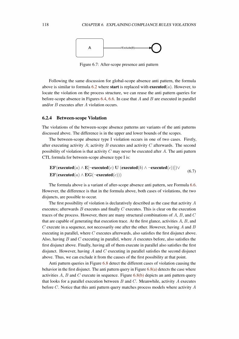
118 CHAPTER 6. EXPLAINING COMPLIANCE RULES VIOLATIONS
Figure 6.7: After-scope presence anti pattern
Following the same discussion for global-scope absence anti pattern, the formulaabove is similar to formula 6.2 where start is replaced with executed(a). However, tolocate the violation on the process structure, we can reuse the anti pattern queries forbefore-scope absence in Figures 6.4, 6.6. In case that A and B are executed in paralleland/or B executes after A violation occurs.
6.2.4 Between-scope Violation
The violations of the between-scope absence patterns are variants of the anti patternsdiscussed above. The difference is in the upper and lower bounds of the scopes.
The between-scope absence type I violation occurs in one of two cases. Firstly,after executing activity A; activity B executes and activity C afterwards. The secondpossibility of violation is that activity C may never be executed after A. The anti patternCTL formula for between-scope absence type I is:
EF(executed(a) ∧E[¬executed(c)U (executed(b) ∧ ¬executed(c))])∨EF(executed(a) ∧EG(¬executed(c)))
(6.7)
The formula above is a variant of after-scope absence anti pattern, see Formula 6.6.However, the difference is that in the formula above, both cases of violations, the twodisjuncts, are possible to occur.
The first possibility of violation is declaratively described as the case that activity A
executes; afterwards B executes and finally C executes. This is clear on the executiontraces of the process. However, there are many structural combinations of A, B, and C
that are capable of generating that execution trace. At the first glance, activities A, B, andC execute in a sequence, not necessarily one after the other. However, having A and B
executing in parallel, where C executes afterwards, also satisfies the first disjunct above.Also, having B and C executing in parallel, where A executes before, also satisfies thefirst disjunct above. Finally, having all of them execute in parallel also satisfies the firstdisjunct. However, having A and C executing in parallel satisfies the second disjunctabove. Thus, we can exclude it from the causes of the first possibility at that point.
Anti pattern queries in Figure 6.8 detect the different cases of violation causing thebehavior in the first disjunct. The anti pattern query in Figure 6.8(a) detects the case whereactivities A, B and C execute in sequence. Figure 6.8(b) depicts an anti pattern querythat looks for a parallel execution between B and C. Meanwhile, activity A executesbefore C. Notice that this anti pattern query matches process models where activity A
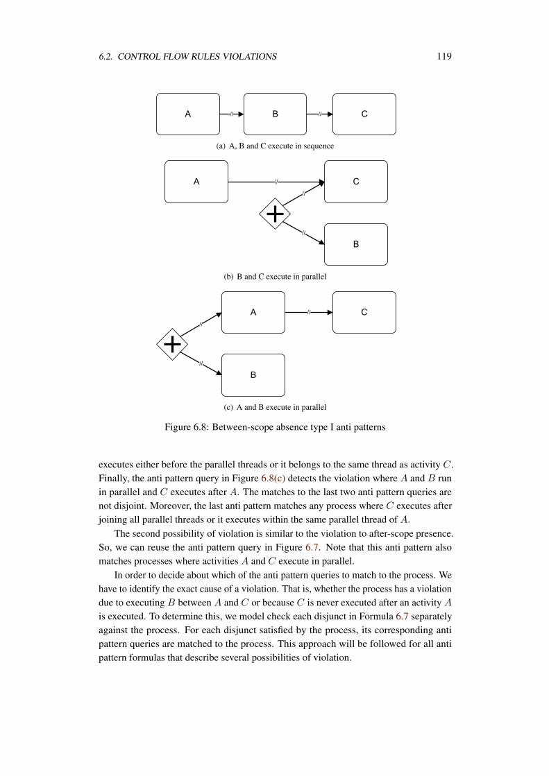
6.2. CONTROL FLOW RULES VIOLATIONS 119
(a) A, B and C execute in sequence
(b) B and C execute in parallel
(c) A and B execute in parallel
Figure 6.8: Between-scope absence type I anti patterns
executes either before the parallel threads or it belongs to the same thread as activity C.Finally, the anti pattern query in Figure 6.8(c) detects the violation where A and B runin parallel and C executes after A. The matches to the last two anti pattern queries arenot disjoint. Moreover, the last anti pattern matches any process where C executes afterjoining all parallel threads or it executes within the same parallel thread of A.
The second possibility of violation is similar to the violation to after-scope presence.So, we can reuse the anti pattern query in Figure 6.7. Note that this anti pattern alsomatches processes where activities A and C execute in parallel.
In order to decide about which of the anti pattern queries to match to the process. Wehave to identify the exact cause of a violation. That is, whether the process has a violationdue to executing B between A and C or because C is never executed after an activity A
is executed. To determine this, we model check each disjunct in Formula 6.7 separatelyagainst the process. For each disjunct satisfied by the process, its corresponding antipattern queries are matched to the process. This approach will be followed for all antipattern formulas that describe several possibilities of violation.
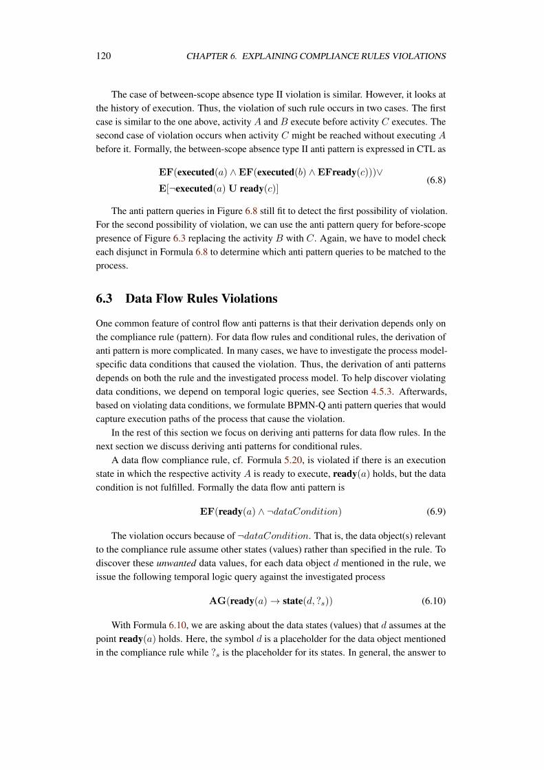
120 CHAPTER 6. EXPLAINING COMPLIANCE RULES VIOLATIONS
The case of between-scope absence type II violation is similar. However, it looks atthe history of execution. Thus, the violation of such rule occurs in two cases. The firstcase is similar to the one above, activity A and B execute before activity C executes. Thesecond case of violation occurs when activity C might be reached without executing A
before it. Formally, the between-scope absence type II anti pattern is expressed in CTL as
EF(executed(a) ∧EF(executed(b) ∧EFready(c)))∨E[¬executed(a)U ready(c)]
(6.8)
The anti pattern queries in Figure 6.8 still fit to detect the first possibility of violation.For the second possibility of violation, we can use the anti pattern query for before-scopepresence of Figure 6.3 replacing the activity B with C. Again, we have to model checkeach disjunct in Formula 6.8 to determine which anti pattern queries to be matched to theprocess.
6.3 Data Flow Rules Violations
One common feature of control flow anti patterns is that their derivation depends only onthe compliance rule (pattern). For data flow rules and conditional rules, the derivation ofanti pattern is more complicated. In many cases, we have to investigate the process model-specific data conditions that caused the violation. Thus, the derivation of anti patternsdepends on both the rule and the investigated process model. To help discover violatingdata conditions, we depend on temporal logic queries, see Section 4.5.3. Afterwards,based on violating data conditions, we formulate BPMN-Q anti pattern queries that wouldcapture execution paths of the process that cause the violation.
In the rest of this section we focus on deriving anti patterns for data flow rules. In thenext section we discuss deriving anti patterns for conditional rules.
A data flow compliance rule, cf. Formula 5.20, is violated if there is an executionstate in which the respective activity A is ready to execute, ready(a) holds, but the datacondition is not fulfilled. Formally the data flow anti pattern is
EF(ready(a) ∧ ¬dataCondition) (6.9)
The violation occurs because of ¬dataCondition. That is, the data object(s) relevantto the compliance rule assume other states (values) rather than specified in the rule. Todiscover these unwanted data values, for each data object d mentioned in the rule, weissue the following temporal logic query against the investigated process
AG(ready(a) → state(d, ?s)) (6.10)
With Formula 6.10, we are asking about the data states (values) that d assumes at thepoint ready(a) holds. Here, the symbol d is a placeholder for the data object mentionedin the compliance rule while ?s is the placeholder for its states. In general, the answer to

6.3. DATA FLOW RULES VIOLATIONS 121
such a query delivers the different data object states that make the statement hold. Thegeneral form of the query result complies with Formula 5.18. We can exclude the dataobject values mentioned in the compliance rule from those returned as the temporal logicquery answer. For each remaining value sr, we seek to build a BPMN-Q anti patternquery that highlights the execution path from the point d was assigned that value sr untilthe activity A is reached.
Recall that each data object d assumes a finite set of states. Also, for each data objectwe assume a known initial state. To help explain how anti patterns are derived, we usean example. Consider the banking business process in Figure 5.26 that handles the “Risk”data object. the set of possible states for the “Risk” object is initial, high, low. Now,consider the data flow compliance rule
AG(ready(Open Correspondent Account) → state(Risk, low))
which we discussed in Section 5.5. We learned that the above rule is violated by thebanking process model. Issuing the temporal logic query
AG(ready(Open Correspondent Account) → state(Risk, ?s))
we receive the following answer to the query
state(Risk, initial) ∨ state(Risk, high) ∨ state(Risk, low)
We can discard state(Risk, low) from the answer since it is the value required by therule. Having this state in the query answer means that there are some cases where the“Open Correspondent Account” activity is ready to execute while the “Risk” object takesthe low value.
The other two data states, namely initial and high, are the causes of the violations.The value initial in the query answer tells us that there are execution path(s) where the“Risk” data object was not updated at all. That is, it keeps its initial state until the “OpenCorrespondent Account” activity is reached. To capture this situation on the processstructure, we need to formulate an anti pattern query where there is an execution path fromthe start of the process to the “Open Correspondent Account” activity that excludes allactivities updating the “Risk” object. It is easy to investigate the process model for thoseactivities that update the “Risk” object. We call this set of activities updateRisk. Withthis information in hand, we can formulate an anti pattern BPMN-Q query as shown inFigure 6.9 where d is replaced with “Risk” and A is replaced with “Open CorrespondentAccount”.
The other cases of violations occur due to setting the data object to some unwantedstate that is kept until the activity in the compliance rule is reached. For the case in hand,The “Risk” object could be set to high and it keeps that value until “Open CorrespondentAccount” is reached. Thus, on the process structure, we need to find an execution pathfrom some activity that sets the “Risk” to high to the open account activity. However, tohighlight correct parts of the process, we have to be sure to exclude any activity on the
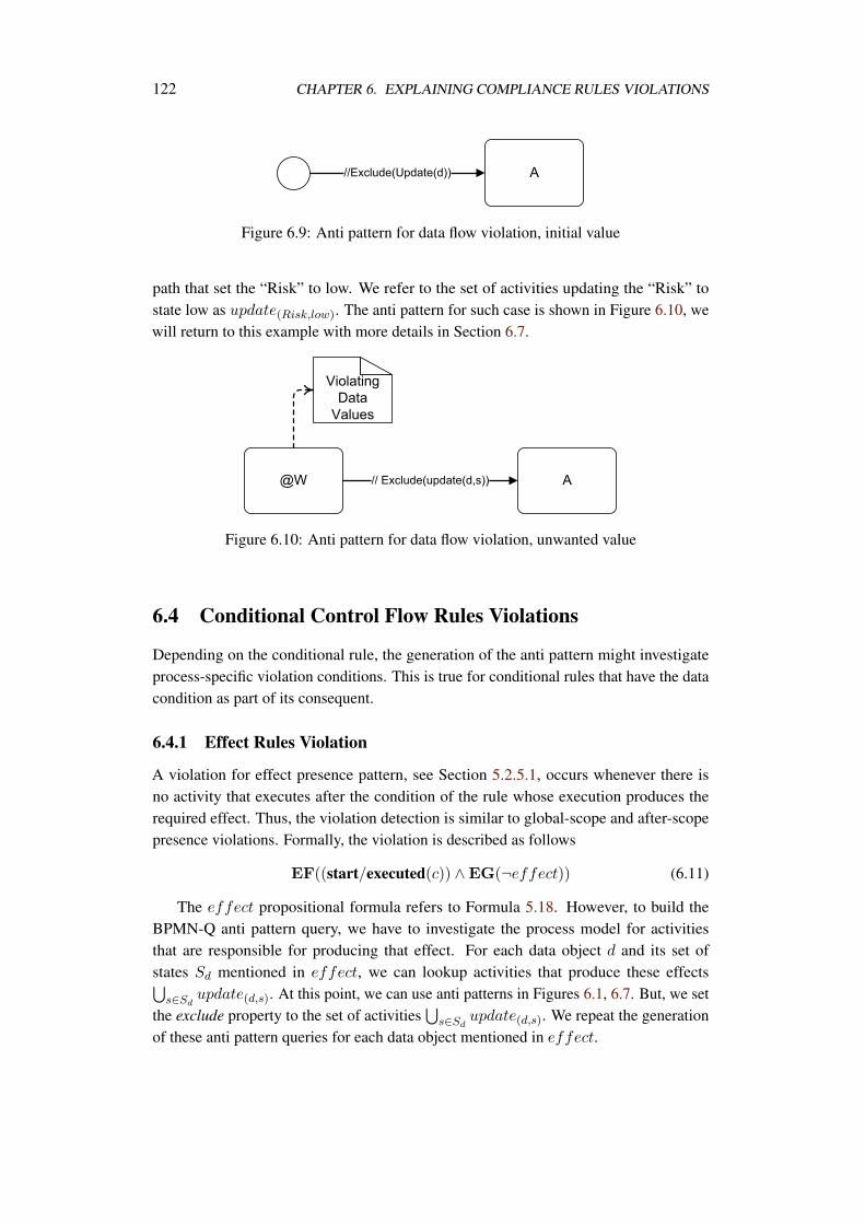
122 CHAPTER 6. EXPLAINING COMPLIANCE RULES VIOLATIONS
Figure 6.9: Anti pattern for data flow violation, initial value
path that set the “Risk” to low. We refer to the set of activities updating the “Risk” tostate low as update(Risk,low). The anti pattern for such case is shown in Figure 6.10, wewill return to this example with more details in Section 6.7.
Figure 6.10: Anti pattern for data flow violation, unwanted value
6.4 Conditional Control Flow Rules Violations
Depending on the conditional rule, the generation of the anti pattern might investigateprocess-specific violation conditions. This is true for conditional rules that have the datacondition as part of its consequent.
6.4.1 Effect Rules Violation
A violation for effect presence pattern, see Section 5.2.5.1, occurs whenever there isno activity that executes after the condition of the rule whose execution produces therequired effect. Thus, the violation detection is similar to global-scope and after-scopepresence violations. Formally, the violation is described as follows
EF((start/executed(c)) ∧EG(¬effect)) (6.11)
The effect propositional formula refers to Formula 5.18. However, to build theBPMN-Q anti pattern query, we have to investigate the process model for activitiesthat are responsible for producing that effect. For each data object d and its set ofstates Sd mentioned in effect, we can lookup activities that produce these effects
s∈Sdupdate(d,s). At this point, we can use anti patterns in Figures 6.1, 6.7. But, we set
the exclude property to the set of activities
s∈Sdupdate(d,s). We repeat the generation
of these anti pattern queries for each data object mentioned in effect.
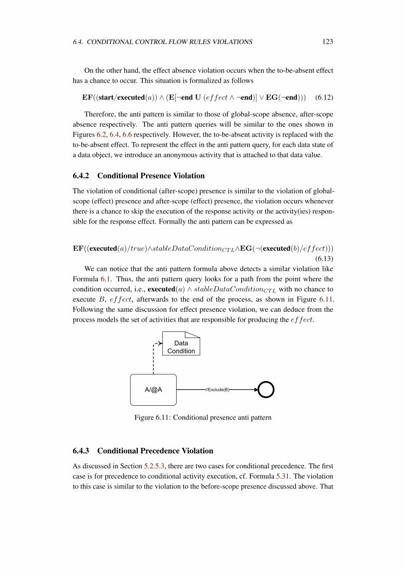
6.4. CONDITIONAL CONTROL FLOW RULES VIOLATIONS 123
On the other hand, the effect absence violation occurs when the to-be-absent effecthas a chance to occur. This situation is formalized as follows
EF((start/executed(a)) ∧ (E[¬end U (effect ∧ ¬end)] ∨EG(¬end))) (6.12)
Therefore, the anti pattern is similar to those of global-scope absence, after-scopeabsence respectively. The anti pattern queries will be similar to the ones shown inFigures 6.2, 6.4, 6.6 respectively. However, the to-be-absent activity is replaced with theto-be-absent effect. To represent the effect in the anti pattern query, for each data state ofa data object, we introduce an anonymous activity that is attached to that data value.
6.4.2 Conditional Presence Violation
The violation of conditional (after-scope) presence is similar to the violation of global-scope (effect) presence and after-scope (effect) presence, the violation occurs wheneverthere is a chance to skip the execution of the response activity or the activity(ies) respon-sible for the response effect. Formally the anti pattern can be expressed as
EF((executed(a)/true)∧stableDataConditionCTL∧EG(¬(executed(b)/effect)))(6.13)
We can notice that the anti pattern formula above detects a similar violation likeFormula 6.1. Thus, the anti pattern query looks for a path from the point where thecondition occurred, i.e., executed(a) ∧ stableDataConditionCTL with no chance toexecute B, effect, afterwards to the end of the process, as shown in Figure 6.11.Following the same discussion for effect presence violation, we can deduce from theprocess models the set of activities that are responsible for producing the effect.
Figure 6.11: Conditional presence anti pattern
6.4.3 Conditional Precedence Violation
As discussed in Section 5.2.5.3, there are two cases for conditional precedence. The firstcase is for precedence to conditional activity execution, cf. Formula 5.31. The violationto this case is similar to the violation to the before-scope presence discussed above. That
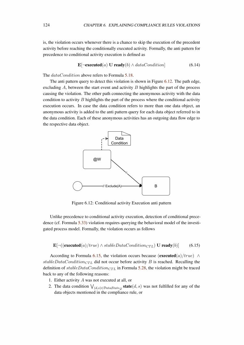
124 CHAPTER 6. EXPLAINING COMPLIANCE RULES VIOLATIONS
is, the violation occurs whenever there is a chance to skip the execution of the precedentactivity before reaching the conditionally executed activity. Formally, the anti pattern forprecedence to conditional activity execution is defined as
E[¬executed(a)U ready(b) ∧ dataCondition] (6.14)
The dataCondition above refers to Formula 5.18.The anti pattern query to detect this violation is shown in Figure 6.12. The path edge,
excluding A, between the start event and activity B highlights the part of the processcausing the violation. The other path connecting the anonymous activity with the datacondition to activity B highlights the part of the process where the conditional activityexecution occurs. In case the data condition refers to more than one data object, ananonymous activity is added to the anti pattern query for each data object referred to inthe data condition. Each of these anonymous activities has an outgoing data flow edge tothe respective data object.
Figure 6.12: Conditional activity Execution anti pattern
Unlike precedence to conditional activity execution, detection of conditional prece-dence (cf. Formula 5.33) violation requires querying the behavioral model of the investi-gated process model. Formally, the violation occurs as follows
E[¬((executed(a)/true) ∧ stableDataConditionCTL) U ready(b)] (6.15)
According to Formula 6.15, the violation occurs because (executed(a)/true) ∧stableDataConditionCTL did not occur before activity B is reached. Recalling thedefinition of stableDataConditionCTL in Formula 5.28, the violation might be tracedback to any of the following reasons:
1. Either activity A was not executed at all, or2. The data condition
(d,s)∈DataStateQ state(d, s) was not fulfilled for any of the
data objects mentioned in the compliance rule, or
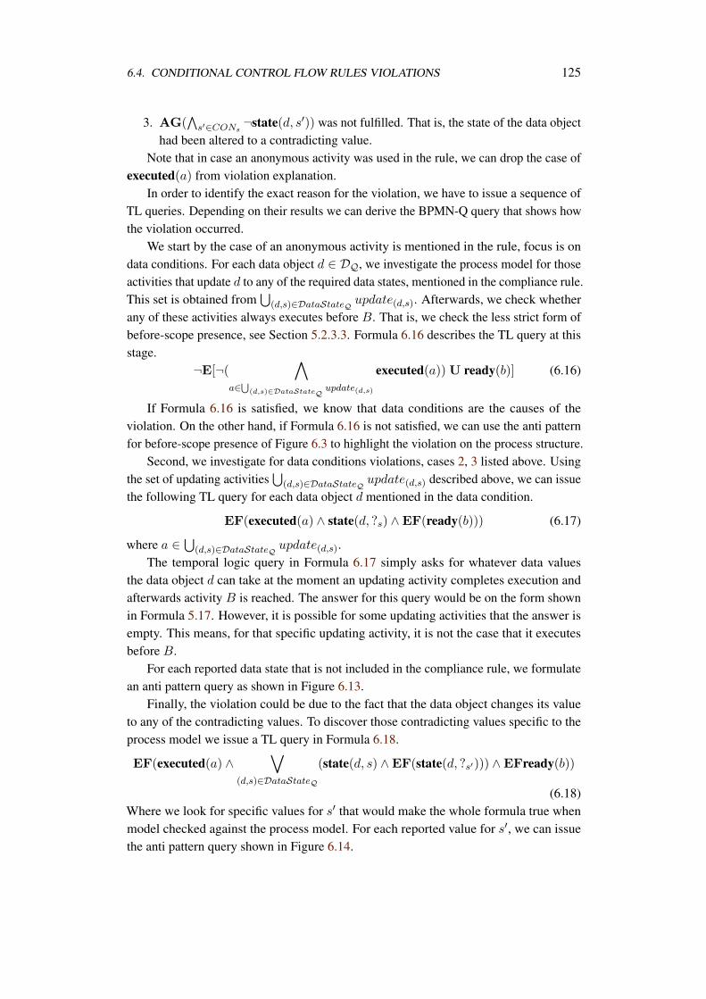
6.4. CONDITIONAL CONTROL FLOW RULES VIOLATIONS 125
3. AG(
s′∈CONs¬state(d, s′)) was not fulfilled. That is, the state of the data object
had been altered to a contradicting value.Note that in case an anonymous activity was used in the rule, we can drop the case of
executed(a) from violation explanation.In order to identify the exact reason for the violation, we have to issue a sequence of
TL queries. Depending on their results we can derive the BPMN-Q query that shows howthe violation occurred.
We start by the case of an anonymous activity is mentioned in the rule, focus is ondata conditions. For each data object d ∈ DQ, we investigate the process model for thoseactivities that update d to any of the required data states, mentioned in the compliance rule.This set is obtained from
(d,s)∈DataStateQ update(d,s). Afterwards, we check whether
any of these activities always executes before B. That is, we check the less strict form ofbefore-scope presence, see Section 5.2.3.3. Formula 6.16 describes the TL query at thisstage.
¬E[¬(
a∈
(d,s)∈DataStateQupdate(d,s)
executed(a))U ready(b)] (6.16)
If Formula 6.16 is satisfied, we know that data conditions are the causes of theviolation. On the other hand, if Formula 6.16 is not satisfied, we can use the anti patternfor before-scope presence of Figure 6.3 to highlight the violation on the process structure.
Second, we investigate for data conditions violations, cases 2, 3 listed above. Usingthe set of updating activities
(d,s)∈DataStateQ update(d,s) described above, we can issue
the following TL query for each data object d mentioned in the data condition.
EF(executed(a) ∧ state(d, ?s) ∧EF(ready(b))) (6.17)
where a ∈
(d,s)∈DataStateQ update(d,s).The temporal logic query in Formula 6.17 simply asks for whatever data values
the data object d can take at the moment an updating activity completes execution andafterwards activity B is reached. The answer for this query would be on the form shownin Formula 5.17. However, it is possible for some updating activities that the answer isempty. This means, for that specific updating activity, it is not the case that it executesbefore B.
For each reported data state that is not included in the compliance rule, we formulatean anti pattern query as shown in Figure 6.13.
Finally, the violation could be due to the fact that the data object changes its valueto any of the contradicting values. To discover those contradicting values specific to theprocess model we issue a TL query in Formula 6.18.
EF(executed(a) ∧
(d,s)∈DataStateQ
(state(d, s) ∧EF(state(d, ?s′))) ∧EFready(b))
(6.18)Where we look for specific values for s′ that would make the whole formula true whenmodel checked against the process model. For each reported value for s′, we can issuethe anti pattern query shown in Figure 6.14.
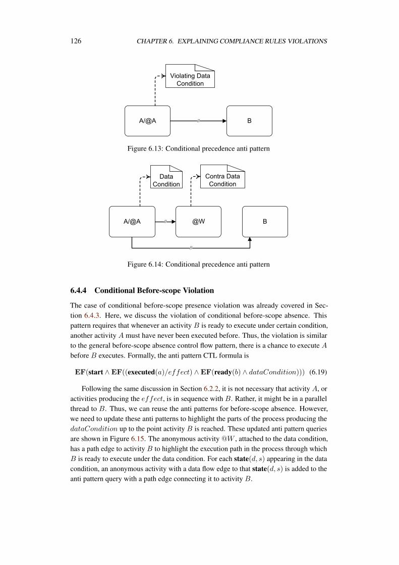
126 CHAPTER 6. EXPLAINING COMPLIANCE RULES VIOLATIONS
Figure 6.13: Conditional precedence anti pattern
Figure 6.14: Conditional precedence anti pattern
6.4.4 Conditional Before-scope Violation
The case of conditional before-scope presence violation was already covered in Sec-tion 6.4.3. Here, we discuss the violation of conditional before-scope absence. Thispattern requires that whenever an activity B is ready to execute under certain condition,another activity A must have never been executed before. Thus, the violation is similarto the general before-scope absence control flow pattern, there is a chance to execute A
before B executes. Formally, the anti pattern CTL formula is
EF(start ∧EF((executed(a)/effect) ∧EF(ready(b) ∧ dataCondition))) (6.19)
Following the same discussion in Section 6.2.2, it is not necessary that activity A, oractivities producing the effect, is in sequence with B. Rather, it might be in a parallelthread to B. Thus, we can reuse the anti patterns for before-scope absence. However,we need to update these anti patterns to highlight the parts of the process producing thedataCondition up to the point activity B is reached. These updated anti pattern queriesare shown in Figure 6.15. The anonymous activity @W , attached to the data condition,has a path edge to activity B to highlight the execution path in the process through whichB is ready to execute under the data condition. For each state(d, s) appearing in the datacondition, an anonymous activity with a data flow edge to that state(d, s) is added to theanti pattern query with a path edge connecting it to activity B.
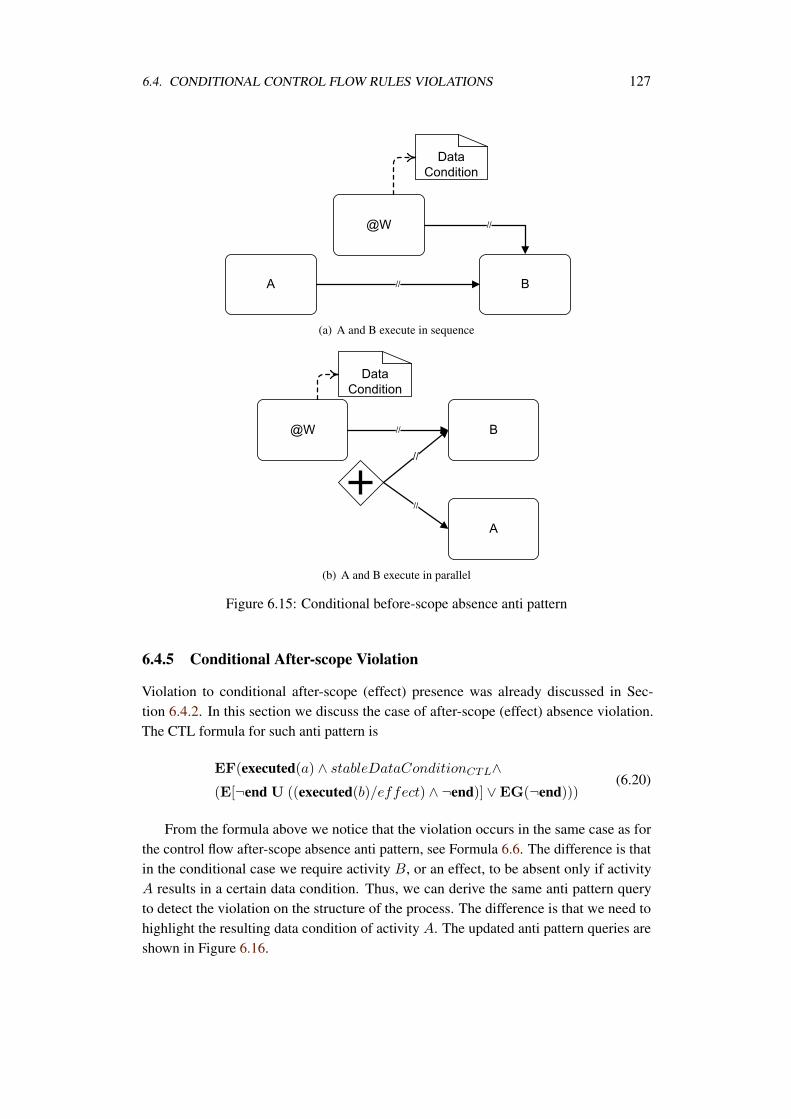
6.4. CONDITIONAL CONTROL FLOW RULES VIOLATIONS 127
(a) A and B execute in sequence
(b) A and B execute in parallel
Figure 6.15: Conditional before-scope absence anti pattern
6.4.5 Conditional After-scope Violation
Violation to conditional after-scope (effect) presence was already discussed in Sec-tion 6.4.2. In this section we discuss the case of after-scope (effect) absence violation.The CTL formula for such anti pattern is
EF(executed(a) ∧ stableDataConditionCTL∧(E[¬end U ((executed(b)/effect) ∧ ¬end)] ∨EG(¬end)))
(6.20)
From the formula above we notice that the violation occurs in the same case as forthe control flow after-scope absence anti pattern, see Formula 6.6. The difference is thatin the conditional case we require activity B, or an effect, to be absent only if activityA results in a certain data condition. Thus, we can derive the same anti pattern queryto detect the violation on the structure of the process. The difference is that we need tohighlight the resulting data condition of activity A. The updated anti pattern queries areshown in Figure 6.16.
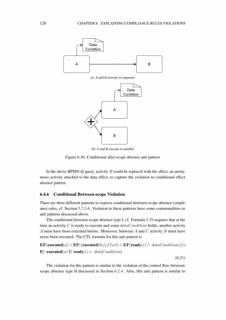
128 CHAPTER 6. EXPLAINING COMPLIANCE RULES VIOLATIONS
(a) A and B execute in sequence
(b) A and B execute in parallel
Figure 6.16: Conditional after-scope absence anti pattern
In the above BPMN-Q query, activity B could be replaced with the effect, an anony-mous activity attached to the data effect, to capture the violation to conditional effectabsence pattern.
6.4.6 Conditional Between-scope Violation
There are three different patterns to express conditional between-scope absence compli-ance rules, cf. Section 5.2.5.6. Violation to these patterns have some commonalities toanti patterns discussed above.
The conditional between-scope absence type I, cf. Formula 5.39 requires that at thetime an activity C is ready to execute and some dataCondition holds; another activityA must have been executed before. Moreover, between A and C activity B must havenever been executed. The CTL formula for this anti pattern is
EF(executed(a) ∧EF((executed(b)/effect) ∧EF(ready(c) ∧ dataCondition)))∨E[¬executed(a)U ready(c) ∧ dataCondition]
(6.21)
The violation for this pattern is similar to the violation of the control flow between-scope absence type II discussed in Section 6.2.4. Also, this anti pattern is similar to
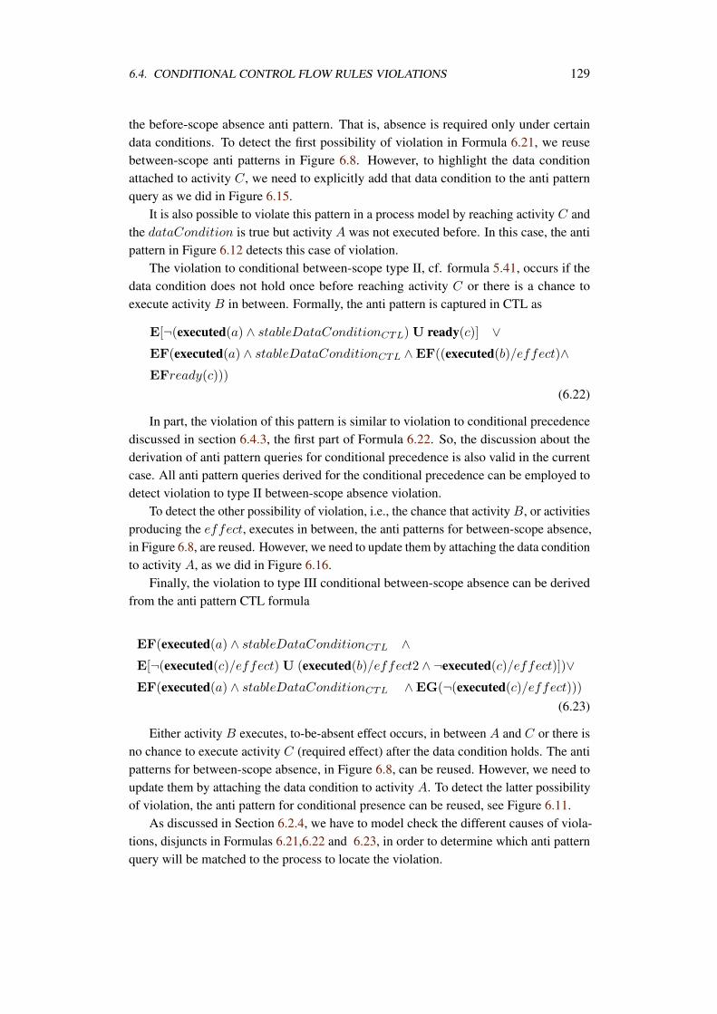
6.4. CONDITIONAL CONTROL FLOW RULES VIOLATIONS 129
the before-scope absence anti pattern. That is, absence is required only under certaindata conditions. To detect the first possibility of violation in Formula 6.21, we reusebetween-scope anti patterns in Figure 6.8. However, to highlight the data conditionattached to activity C, we need to explicitly add that data condition to the anti patternquery as we did in Figure 6.15.
It is also possible to violate this pattern in a process model by reaching activity C andthe dataCondition is true but activity A was not executed before. In this case, the antipattern in Figure 6.12 detects this case of violation.
The violation to conditional between-scope type II, cf. formula 5.41, occurs if thedata condition does not hold once before reaching activity C or there is a chance toexecute activity B in between. Formally, the anti pattern is captured in CTL as
E[¬(executed(a) ∧ stableDataConditionCTL) U ready(c)] ∨EF(executed(a) ∧ stableDataConditionCTL ∧EF((executed(b)/effect)∧EFready(c)))
(6.22)
In part, the violation of this pattern is similar to violation to conditional precedencediscussed in section 6.4.3, the first part of Formula 6.22. So, the discussion about thederivation of anti pattern queries for conditional precedence is also valid in the currentcase. All anti pattern queries derived for the conditional precedence can be employed todetect violation to type II between-scope absence violation.
To detect the other possibility of violation, i.e., the chance that activity B, or activitiesproducing the effect, executes in between, the anti patterns for between-scope absence,in Figure 6.8, are reused. However, we need to update them by attaching the data conditionto activity A, as we did in Figure 6.16.
Finally, the violation to type III conditional between-scope absence can be derivedfrom the anti pattern CTL formula
EF(executed(a) ∧ stableDataConditionCTL ∧E[¬(executed(c)/effect) U (executed(b)/effect2 ∧ ¬executed(c)/effect)])∨EF(executed(a) ∧ stableDataConditionCTL ∧EG(¬(executed(c)/effect)))
(6.23)
Either activity B executes, to-be-absent effect occurs, in between A and C or there isno chance to execute activity C (required effect) after the data condition holds. The antipatterns for between-scope absence, in Figure 6.8, can be reused. However, we need toupdate them by attaching the data condition to activity A. To detect the latter possibilityof violation, the anti pattern for conditional presence can be reused, see Figure 6.11.
As discussed in Section 6.2.4, we have to model check the different causes of viola-tions, disjuncts in Formulas 6.21,6.22 and 6.23, in order to determine which anti patternquery will be matched to the process to locate the violation.
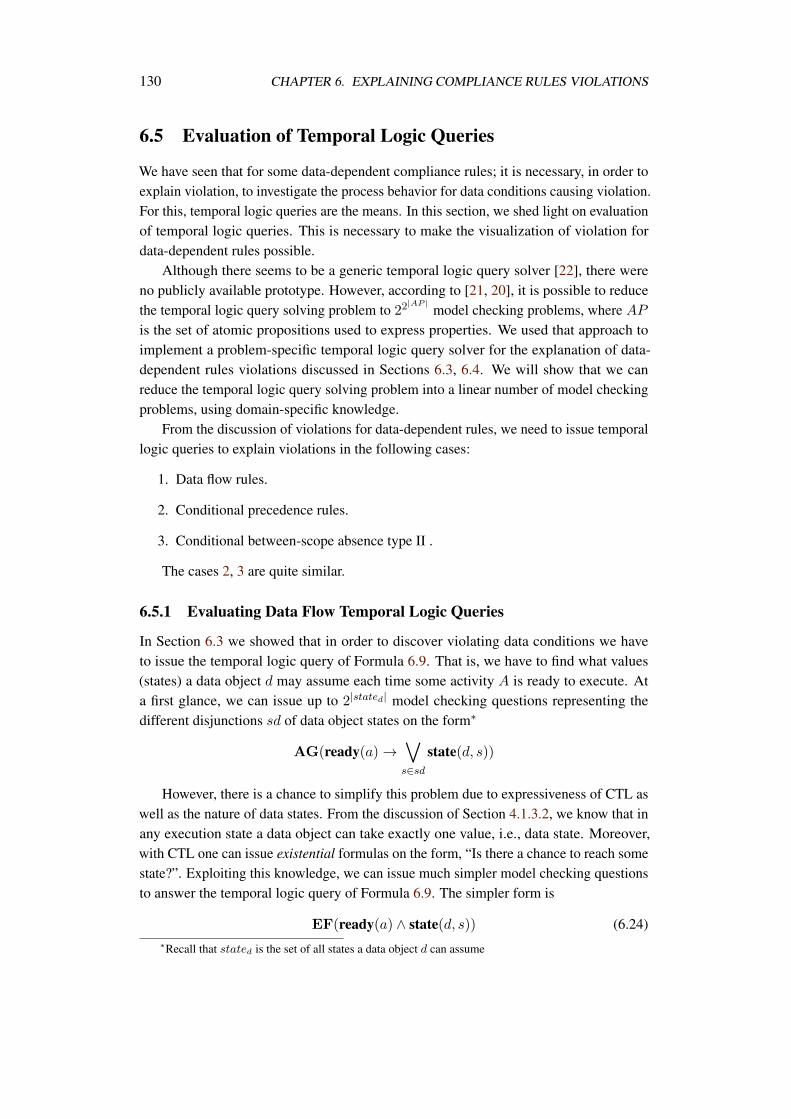
130 CHAPTER 6. EXPLAINING COMPLIANCE RULES VIOLATIONS
6.5 Evaluation of Temporal Logic Queries
We have seen that for some data-dependent compliance rules; it is necessary, in order toexplain violation, to investigate the process behavior for data conditions causing violation.For this, temporal logic queries are the means. In this section, we shed light on evaluationof temporal logic queries. This is necessary to make the visualization of violation fordata-dependent rules possible.
Although there seems to be a generic temporal logic query solver [22], there wereno publicly available prototype. However, according to [21, 20], it is possible to reducethe temporal logic query solving problem to 22
|AP |model checking problems, where AP
is the set of atomic propositions used to express properties. We used that approach toimplement a problem-specific temporal logic query solver for the explanation of data-dependent rules violations discussed in Sections 6.3, 6.4. We will show that we canreduce the temporal logic query solving problem into a linear number of model checkingproblems, using domain-specific knowledge.
From the discussion of violations for data-dependent rules, we need to issue temporallogic queries to explain violations in the following cases:
1. Data flow rules.
2. Conditional precedence rules.
3. Conditional between-scope absence type II .
The cases 2, 3 are quite similar.
6.5.1 Evaluating Data Flow Temporal Logic Queries
In Section 6.3 we showed that in order to discover violating data conditions we haveto issue the temporal logic query of Formula 6.9. That is, we have to find what values(states) a data object d may assume each time some activity A is ready to execute. Ata first glance, we can issue up to 2|stated| model checking questions representing thedifferent disjunctions sd of data object states on the form∗
AG(ready(a) →s∈sd
state(d, s))
However, there is a chance to simplify this problem due to expressiveness of CTL aswell as the nature of data states. From the discussion of Section 4.1.3.2, we know that inany execution state a data object can take exactly one value, i.e., data state. Moreover,with CTL one can issue existential formulas on the form, “Is there a chance to reach somestate?”. Exploiting this knowledge, we can issue much simpler model checking questionsto answer the temporal logic query of Formula 6.9. The simpler form is
EF(ready(a) ∧ state(d, s)) (6.24)∗Recall that stated is the set of all states a data object d can assume
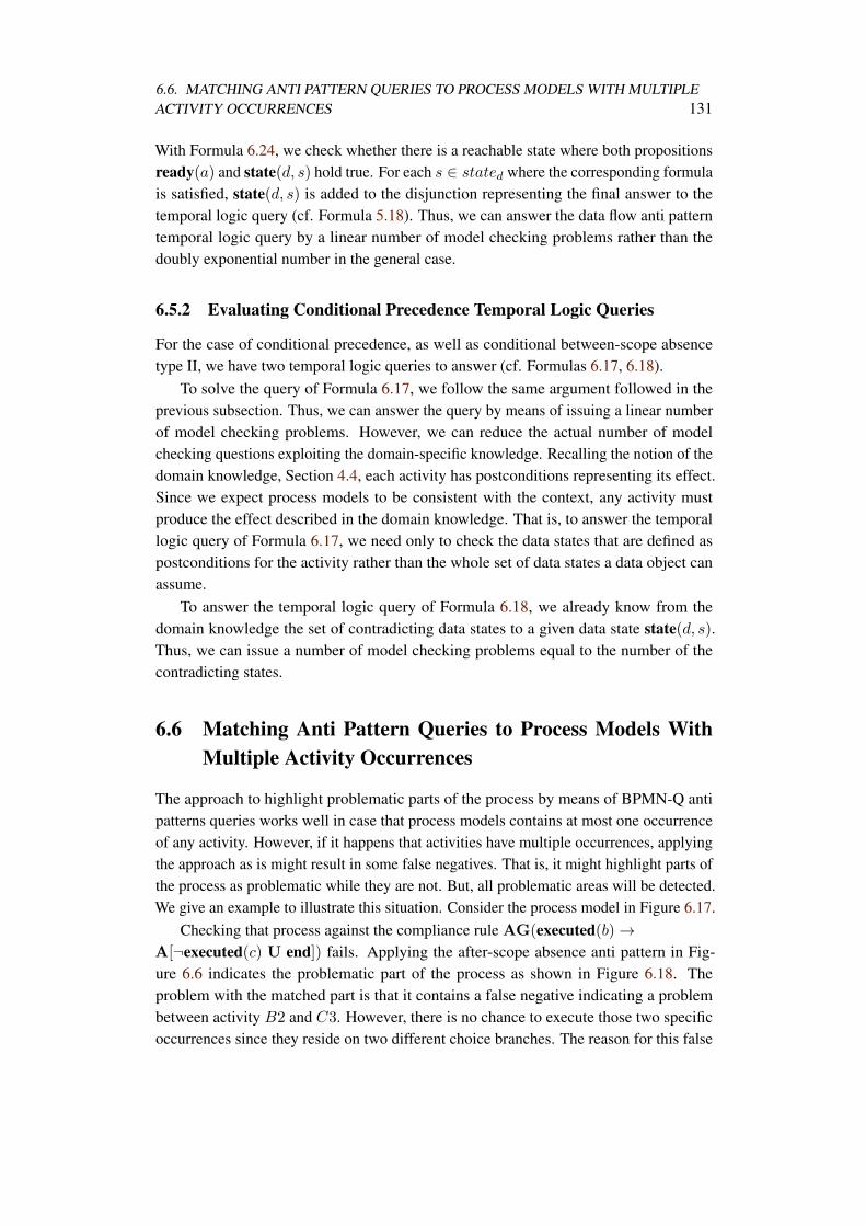
6.6. MATCHING ANTI PATTERN QUERIES TO PROCESS MODELS WITH MULTIPLEACTIVITY OCCURRENCES 131
With Formula 6.24, we check whether there is a reachable state where both propositionsready(a) and state(d, s) hold true. For each s ∈ stated where the corresponding formulais satisfied, state(d, s) is added to the disjunction representing the final answer to thetemporal logic query (cf. Formula 5.18). Thus, we can answer the data flow anti patterntemporal logic query by a linear number of model checking problems rather than thedoubly exponential number in the general case.
6.5.2 Evaluating Conditional Precedence Temporal Logic Queries
For the case of conditional precedence, as well as conditional between-scope absencetype II, we have two temporal logic queries to answer (cf. Formulas 6.17, 6.18).
To solve the query of Formula 6.17, we follow the same argument followed in theprevious subsection. Thus, we can answer the query by means of issuing a linear numberof model checking problems. However, we can reduce the actual number of modelchecking questions exploiting the domain-specific knowledge. Recalling the notion of thedomain knowledge, Section 4.4, each activity has postconditions representing its effect.Since we expect process models to be consistent with the context, any activity mustproduce the effect described in the domain knowledge. That is, to answer the temporallogic query of Formula 6.17, we need only to check the data states that are defined aspostconditions for the activity rather than the whole set of data states a data object canassume.
To answer the temporal logic query of Formula 6.18, we already know from thedomain knowledge the set of contradicting data states to a given data state state(d, s).Thus, we can issue a number of model checking problems equal to the number of thecontradicting states.
6.6 Matching Anti Pattern Queries to Process Models WithMultiple Activity Occurrences
The approach to highlight problematic parts of the process by means of BPMN-Q antipatterns queries works well in case that process models contains at most one occurrenceof any activity. However, if it happens that activities have multiple occurrences, applyingthe approach as is might result in some false negatives. That is, it might highlight parts ofthe process as problematic while they are not. But, all problematic areas will be detected.We give an example to illustrate this situation. Consider the process model in Figure 6.17.
Checking that process against the compliance rule AG(executed(b) →A[¬executed(c) U end]) fails. Applying the after-scope absence anti pattern in Fig-ure 6.6 indicates the problematic part of the process as shown in Figure 6.18. Theproblem with the matched part is that it contains a false negative indicating a problembetween activity B2 and C3. However, there is no chance to execute those two specificoccurrences since they reside on two different choice branches. The reason for this false
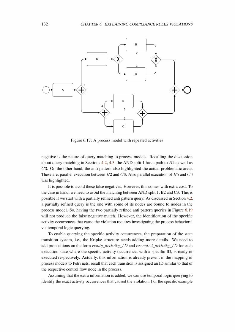
132 CHAPTER 6. EXPLAINING COMPLIANCE RULES VIOLATIONS
Figure 6.17: A process model with repeated activities
negative is the nature of query matching to process models. Recalling the discussionabout query matching in Sections 4.2, 4.3, the AND split 1 has a path to B2 as well asC3. On the other hand, the anti pattern also highlighted the actual problematic areas.These are, parallel execution between B2 and C6. Also parallel execution of B5 and C6
was highlighted.It is possible to avoid these false negatives. However, this comes with extra cost. To
the case in hand, we need to avoid the matching between AND split 1, B2 and C3. This ispossible if we start with a partially refined anti pattern query. As discussed in Section 4.2,a partially refined query is the one with some of its nodes are bound to nodes in theprocess model. So, having the two partially refined anti pattern queries in Figure 6.19will not produce the false negative match. However, the identification of the specificactivity occurrences that cause the violation requires investigating the process behavioralvia temporal logic querying.
To enable querying the specific activity occurrences, the preparation of the statetransition system, i.e., the Kripke structure needs adding more details. We need toadd propositions on the form ready_activity_ID and executed_activity_ID for eachexecution state where the specific activity occurrence, with a specific ID, is ready orexecuted respectively. Actually, this information is already present in the mapping ofprocess models to Petri nets, recall that each transition is assigned an ID similar to that ofthe respective control flow node in the process.
Assuming that the extra information is added, we can use temporal logic querying toidentify the exact activity occurrences that caused the violation. For the specific example
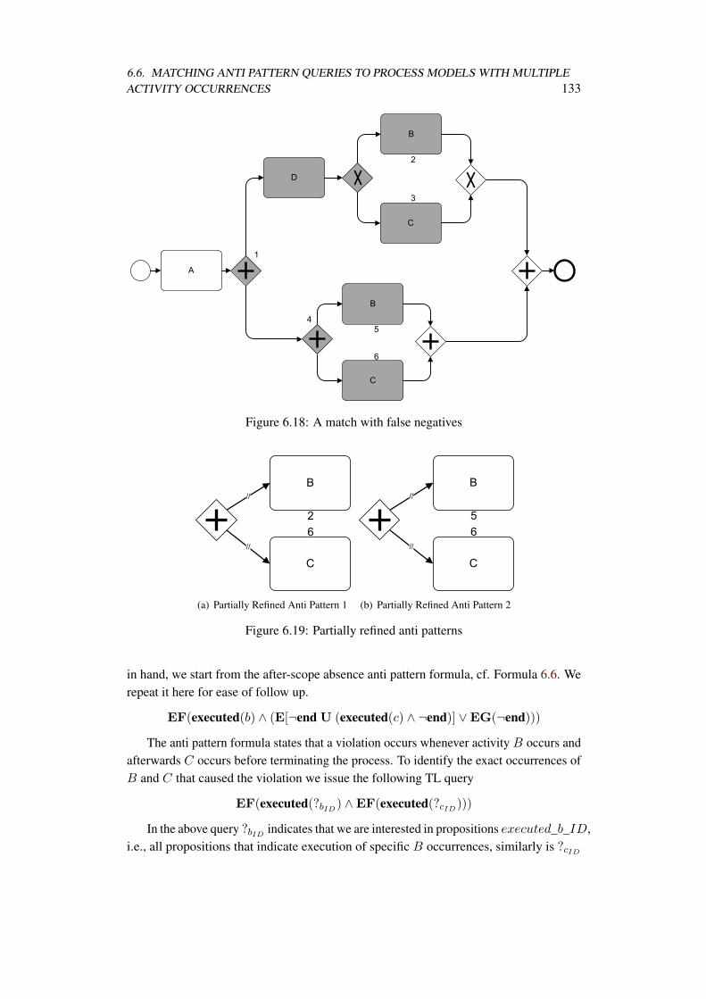
6.6. MATCHING ANTI PATTERN QUERIES TO PROCESS MODELS WITH MULTIPLEACTIVITY OCCURRENCES 133
Figure 6.18: A match with false negatives
(a) Partially Refined Anti Pattern 1 (b) Partially Refined Anti Pattern 2
Figure 6.19: Partially refined anti patterns
in hand, we start from the after-scope absence anti pattern formula, cf. Formula 6.6. Werepeat it here for ease of follow up.
EF(executed(b) ∧ (E[¬end U (executed(c) ∧ ¬end)] ∨EG(¬end)))
The anti pattern formula states that a violation occurs whenever activity B occurs andafterwards C occurs before terminating the process. To identify the exact occurrences ofB and C that caused the violation we issue the following TL query
EF(executed(?bID) ∧EF(executed(?cID)))
In the above query ?bID indicates that we are interested in propositions executed_b_ID,i.e., all propositions that indicate execution of specific B occurrences, similarly is ?cID
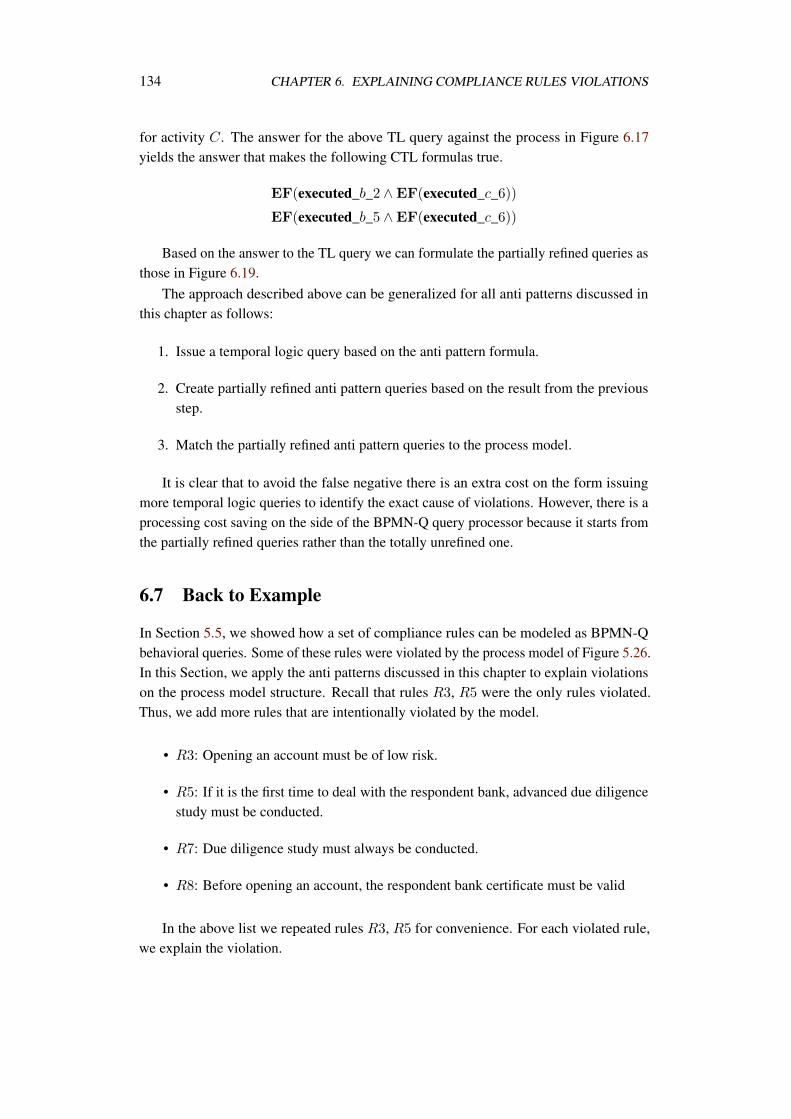
134 CHAPTER 6. EXPLAINING COMPLIANCE RULES VIOLATIONS
for activity C. The answer for the above TL query against the process in Figure 6.17yields the answer that makes the following CTL formulas true.
EF(executed_b_2 ∧EF(executed_c_6))
EF(executed_b_5 ∧EF(executed_c_6))
Based on the answer to the TL query we can formulate the partially refined queries asthose in Figure 6.19.
The approach described above can be generalized for all anti patterns discussed inthis chapter as follows:
1. Issue a temporal logic query based on the anti pattern formula.
2. Create partially refined anti pattern queries based on the result from the previousstep.
3. Match the partially refined anti pattern queries to the process model.
It is clear that to avoid the false negative there is an extra cost on the form issuingmore temporal logic queries to identify the exact cause of violations. However, there is aprocessing cost saving on the side of the BPMN-Q query processor because it starts fromthe partially refined queries rather than the totally unrefined one.
6.7 Back to Example
In Section 5.5, we showed how a set of compliance rules can be modeled as BPMN-Qbehavioral queries. Some of these rules were violated by the process model of Figure 5.26.In this Section, we apply the anti patterns discussed in this chapter to explain violationson the process model structure. Recall that rules R3, R5 were the only rules violated.Thus, we add more rules that are intentionally violated by the model.
• R3: Opening an account must be of low risk.
• R5: If it is the first time to deal with the respondent bank, advanced due diligencestudy must be conducted.
• R7: Due diligence study must always be conducted.
• R8: Before opening an account, the respondent bank certificate must be valid
In the above list we repeated rules R3, R5 for convenience. For each violated rule,we explain the violation.
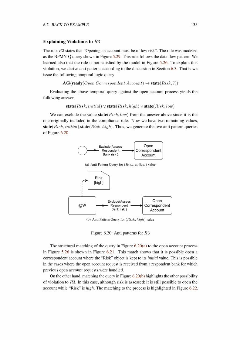
6.7. BACK TO EXAMPLE 135
Explaining Violations to R3
The rule R3 states that “Opening an account must be of low risk”. The rule was modeledas the BPMN-Q query shown in Figure 5.29. This rule follows the data flow pattern. Welearned also that the rule is not satisfied by the model in Figure 5.26. To explain thisviolation, we derive anti patterns according to the discussion in Section 6.3. That is weissue the following temporal logic query
AG(ready(Open Correspondent Account) → state(Risk, ?))
Evaluating the above temporal query against the open account process yields thefollowing answer
state(Risk, initial) ∨ state(Risk, high) ∨ state(Risk, low)
We can exclude the value state(Risk, low) from the answer above since it is theone originally included in the compliance rule. Now we have two remaining values,state(Risk, initial),state(Risk, high). Thus, we generate the two anti pattern queriesof Figure 6.20.
(a) Anti Pattern Query for (Risk, initial) value
(b) Anti Pattern Query for (Risk, high) value
Figure 6.20: Anti patterns for R3
The structural matching of the query in Figure 6.20(a) to the open account processin Figure 5.26 is shown in Figure 6.21. This match shows that it is possible open acorrespondent account where the “Risk” object is kept to its initial value. This is possiblein the cases where the open account request is received from a respondent bank for whichprevious open account requests were handled.
On the other hand, matching the query in Figure 6.20(b) highlights the other possibilityof violation to R3. In this case, although risk is assessed; it is still possible to open theaccount while “Risk” is high. The matching to the process is highlighted in Figure 6.22.
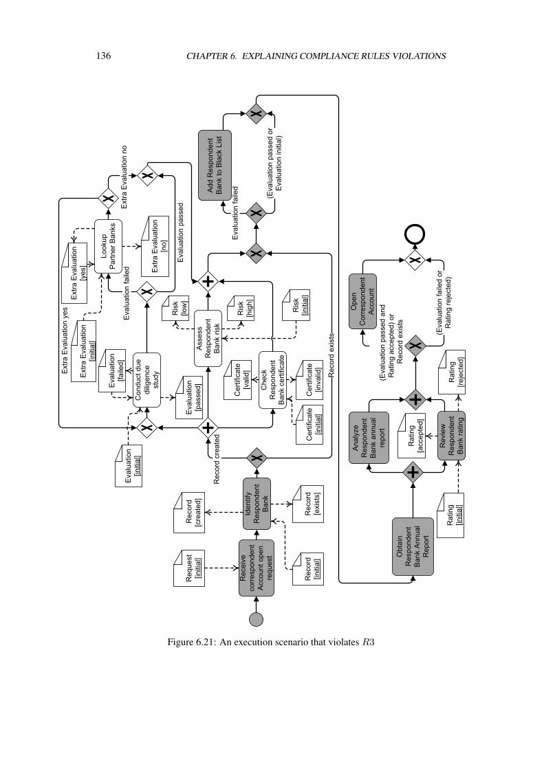
136 CHAPTER 6. EXPLAINING COMPLIANCE RULES VIOLATIONS
Figure 6.21: An execution scenario that violates R3
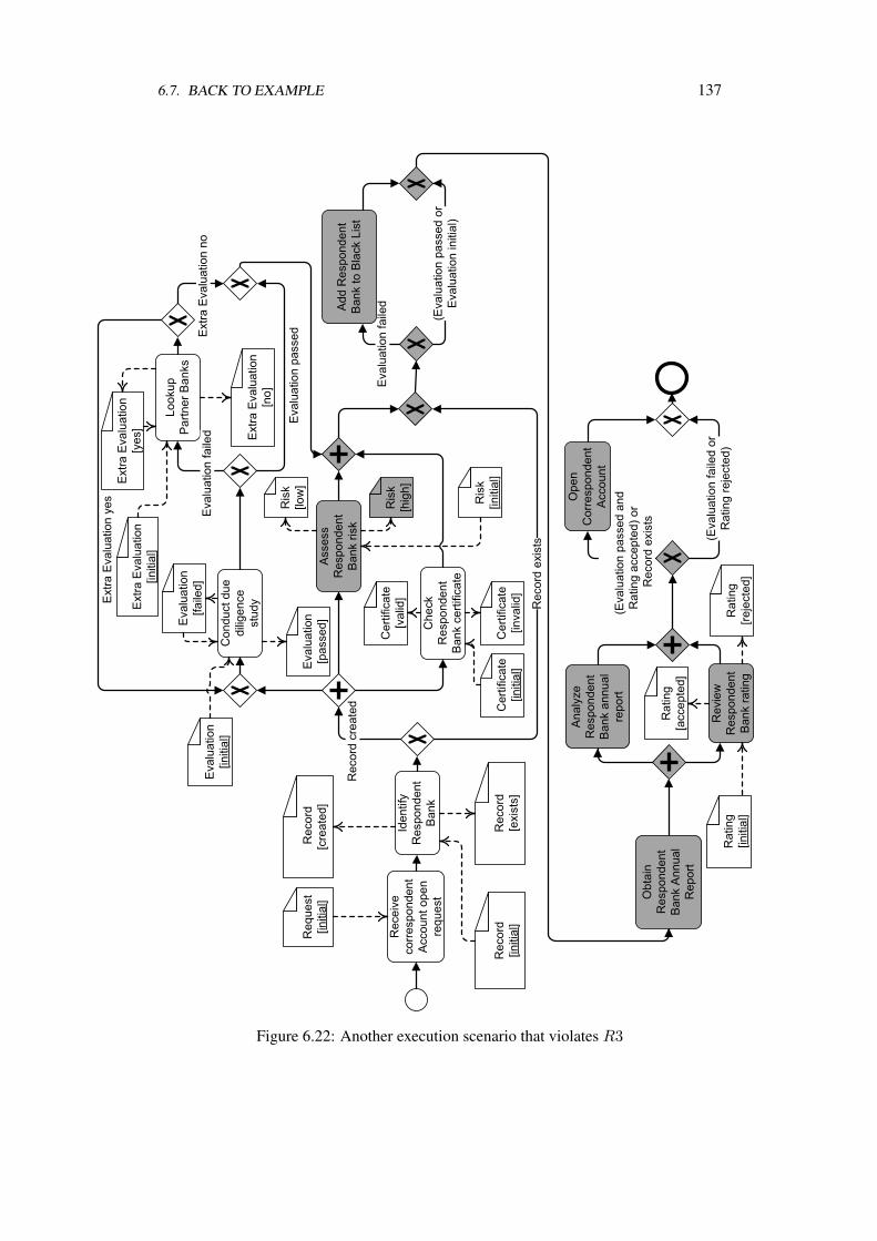
6.7. BACK TO EXAMPLE 137
Figure 6.22: Another execution scenario that violates R3
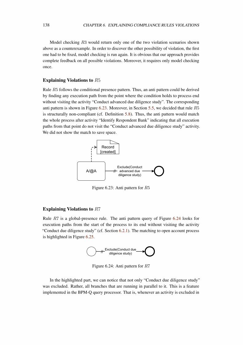
138 CHAPTER 6. EXPLAINING COMPLIANCE RULES VIOLATIONS
Model checking R3 would return only one of the two violation scenarios shownabove as a counterexample. In order to discover the other possibility of violation, the firstone had to be fixed, model checking is run again. It is obvious that our approach providescomplete feedback on all possible violations. Moreover, it requires only model checkingonce.
Explaining Violations to R5
Rule R5 follows the conditional presence pattern. Thus, an anti pattern could be derivedby finding any execution path from the point where the condition holds to process endwithout visiting the activity “Conduct advanced due diligence study”. The correspondinganti pattern is shown in Figure 6.23. Moreover, in Section 5.5, we decided that rule R5
is structurally non-compliant (cf. Definition 5.8). Thus, the anti pattern would matchthe whole process after activity “Identify Respondent Bank” indicating that all executionpaths from that point do not visit the “Conduct advanced due diligence study” activity.We did not show the match to save space.
Figure 6.23: Anti pattern for R5
Explaining Violations to R7
Rule R7 is a global-presence rule. The anti pattern query of Figure 6.24 looks forexecution paths from the start of the process to its end without visiting the activity“Conduct due diligence study” (cf. Section 6.2.1). The matching to open account processis highlighted in Figure 6.25.
Figure 6.24: Anti pattern for R7
In the highlighted part, we can notice that not only “Conduct due diligence study”was excluded. Rather, all branches that are running in parallel to it. This is a featureimplemented in the BPM-Q query processor. That is, whenever an activity is excluded in
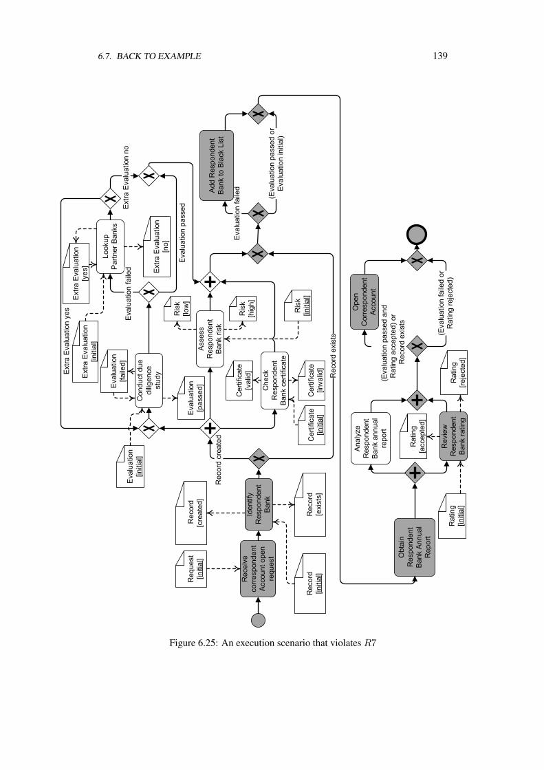
6.7. BACK TO EXAMPLE 139
Figure 6.25: An execution scenario that violates R7
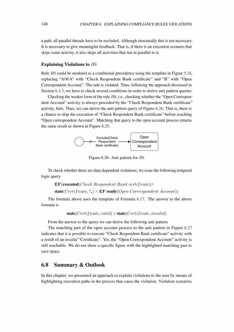
140 CHAPTER 6. EXPLAINING COMPLIANCE RULES VIOLATIONS
a path, all parallel threads have to be excluded. Although structurally this is not necessary.It is necessary to give meaningful feedback. That is, if there is an execution scenario thatskips some activity, it also skips all activities that run in parallel to it.
Explaining Violations to R8
Rule R8 could be modeled as a conditional precedence using the template in Figure 5.18,replacing “A/@A” with “Check Respondent Bank certificate” and “B” with “OpenCorrespondent Account”. The rule is violated. Thus, following the approach discussed inSection 6.4.3, we have to check several conditions in order to derive anti pattern queries.
Checking the weaker form of the rule R8, i.e., checking whether the “Open Correspon-dent Account” activity is always preceded by the “Check Respondent Bank certificate”activity, fails. Thus, we can derive the anti pattern query of Figure 6.26. That is, there isa chance to skip the execution of “Check Respondent Bank certificate” before reaching“Open correspondent Account”. Matching that query to the open account process returnsthe same result as shown in Figure 6.25.
Figure 6.26: Anti pattern for R8
To check whether there are data-dependent violations, we issue the following temporallogic query
EF(executed(Check Respondent Bank certificate)∧state(Certificate, ?s) ∧EF ready(Open Correspondent Account))
The formula above uses the template of Formula 6.17. The answer to the aboveformula is
state(Certificate, valid) ∨ state(Certificate, invalid)
From the answer to the query we can derive the following anti patternThe matching part of the open account process to the anti pattern in Figure 6.27
indicates that it is possible to execute “Check Respondent Bank certificate” activity witha result of an invalid “Certificate”. Yet, the “Open Correspondent Account” activity isstill reachable. We do not show a specific figure with the highlighted matching part tosave space.
6.8 Summary & Outlook
In this chapter, we presented an approach to explain violations to the user by means ofhighlighting execution paths in the process that cause the violation. Violation scenarios
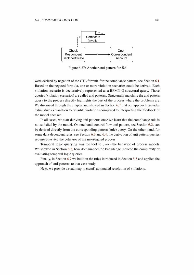
6.8. SUMMARY & OUTLOOK 141
Figure 6.27: Another anti pattern for R8
were derived by negation of the CTL formula for the compliance pattern, see Section 6.1.Based on the negated formula, one or more violation scenarios could be derived. Eachviolation scenario is declaratively represented as a BPMN-Q structural query. Thosequeries (violation scenarios) are called anti patterns. Structurally matching the anti patternquery to the process directly highlights the part of the process where the problems are.We discussed through the chapter and showed in Section 6.7 that our approach providesexhaustive explanation to possible violations compared to interpreting the feedback ofthe model checker.
In all cases, we start deriving anti patterns once we learn that the compliance rule isnot satisfied by the model. On one hand, control flow anti pattern, see Section 6.2, canbe derived directly from the corresponding pattern (rule) query. On the other hand, forsome data-dependent rules, see Section 6.3 and 6.4, the derivation of anti pattern queriesrequire querying the behavior of the investigated process.
Temporal logic querying was the tool to query the behavior of process models.We showed in Section 6.5, how domain-specific knowledge reduced the complexity ofevaluating temporal logic queries.
Finally, in Section 6.7 we built on the rules introduced in Section 5.5 and applied theapproach of anti patterns to that case study.
Next, we provide a road map to (semi) automated resolution of violations.

Chapter 7
Resolution of Compliance Violation
In Chapters 5, 6, we discussed how to model, check and explain violations to compliancerules. Model checking and temporal logics were the formal background to our approach.In this chapter, we address the problem of providing suggestions to the user in order toremove violations and enforce compliance. To this end, model checking and temporallogic techniques fall short to cope with the new problem. Firstly, model checking dealswith the behavioral model of the process while making changes to the process necessitatesdoing modifications on the structural level. Moreover, the changes to be made to theprocess should be kept as minimal as possible; it must keep the changed process modelconsistent with the domain knowledge. Finally, temporal logic is of a declarative naturethat fitted well with the nature of compliance rules. When it comes to modifying theprocess structure, more details have to be added to keep the process operational. Forinstance, a compliance rule which states that “for each received insurance claim there hasto be a reply sent to the client“ abstracts from details like investigating and evaluatingthe claim and comparing it to the client policy before deciding to pay back the claim’samount. All these details must be present to make the process model operational.
While our approach in the previous two chapters was complete. That is, we were ableto decide about compliance for each rule and we were able to explain violations. In thischapter, we give directions for automated resolution of violations. We investigate how farthe domain knowledge can be exploited to help the user find resolutions to the violations.Even if it is not possible to automatically resolve the violation, we help the user assessthe effort needed, in terms of changes to the way business is conducted and understood,to enforce compliance.
To simplify the discussion, we focus on resolving violations to after-scope presence,i.e., G(executed(a) → F(executed(b))). We refer to this rule simply as A leads to B.In this chapter, we discuss the possibilities of resolving violations to this pattern. Lateron, we discuss how resolution to violations of other patterns can be approached.
To reach this objective, the rest of this chapter is organized as follows. In Section 7.1
143
144 CHAPTER 7. RESOLUTION OF COMPLIANCE VIOLATION
we argue that we need a different tool set in order to address the violation resolutionproblem. We study the possible violations to A leads to B rule on the process structurallevel in Section 7.2. Based thereon, we suggest various resolutions and discuss theirapplicability in Section 7.3. Directions to resolve violations to other patterns is given inSection 7.4. Finally, Section 7.5 discusses the limitations of the approach.
7.1 Another Tool Set
We have two problems that temporal logics and model checking cannot address:
• Analyzing the violation on the structure of the process model
• Filling the gap between the abstract compliance rules and the detailed operationalprocess models.
In order to resolve a violation, we have to make modifications to the structure of theprocess model. Modifications can be in the form of adding, removing, or moving activitiesto restore compliance. This necessitates the study of the execution relation betweenactivities A and B, mentioned in the compliance rule. Process decomposition techniquesprovide a good starting point to analyze compliance violation, and thus resolution, onthe structural level. We rely on the concept of process structure tree (PST) [144, 145],which is the process analogue of abstract syntax trees for programs, we give more detailsin Section 7.1.1.
The second problem that appears when we need to provide automated resolution is theabstraction-level gap between compliance rules and operational process models. As statedearlier, process models must have a sufficient amount of details to make it operationaland to meet its business objective. On the other hand, compliance requirements focus ona specific situation and leaves all other details out. Thus, we need a technique that canderive a detailed process that is yet compliant.
To fill the abstraction-level gap between compliance rules and detailed processes, wedepend on automated planning techniques [97]. In automated planning, the planner isgiven three inputs, the initial state, the target state and the action space. It is the planner’stask to find a sequence of actions that can make the system evolve from the initial state tothe target state, see Section 7.1.2 for more details.
7.1.1 Process Structure Tree
The concept of a process structure tree is based on the unique decomposition of a processmodel into fragments. One approach is the decomposition of a model into canonicalsingle entry single exit (SESE) fragments, formally described in [144, 61]. Informally, aSESE fragment is a fragment with exactly one incoming and exactly one outgoing edge.The node sets of two canonical SESE fragments are either disjoint or one contains theother. Following [144], we consider the maximal sequence of nodes to be a canonical
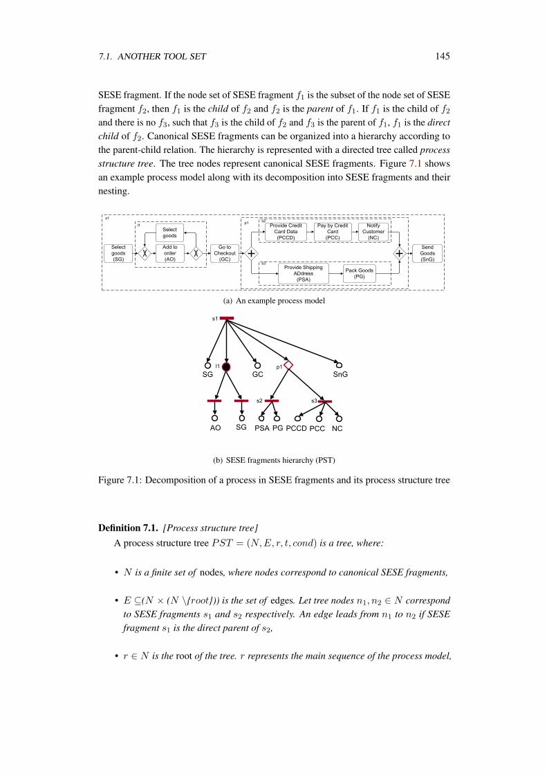
7.1. ANOTHER TOOL SET 145
SESE fragment. If the node set of SESE fragment f1 is the subset of the node set of SESEfragment f2, then f1 is the child of f2 and f2 is the parent of f1. If f1 is the child of f2and there is no f3, such that f3 is the child of f2 and f3 is the parent of f1, f1 is the directchild of f2. Canonical SESE fragments can be organized into a hierarchy according tothe parent-child relation. The hierarchy is represented with a directed tree called processstructure tree. The tree nodes represent canonical SESE fragments. Figure 7.1 showsan example process model along with its decomposition into SESE fragments and theirnesting.
(a) An example process model
(b) SESE fragments hierarchy (PST)
Figure 7.1: Decomposition of a process in SESE fragments and its process structure tree
Definition 7.1. [Process structure tree]
A process structure tree PST = (N,E, r, t, cond) is a tree, where:
• N is a finite set of nodes, where nodes correspond to canonical SESE fragments,
• E ⊆(N × (N \root)) is the set of edges. Let tree nodes n1, n2 ∈ N correspondto SESE fragments s1 and s2 respectively. An edge leads from n1 to n2 if SESEfragment s1 is the direct parent of s2,
• r ∈ N is the root of the tree. r represents the main sequence of the process model,
146 CHAPTER 7. RESOLUTION OF COMPLIANCE VIOLATION
• t : N → act,seq,and,xor,loop is a function assigning a type to eachnode in N : act corresponds to activities, seq—sequences, and, xor—blocksof corresponding type, loop,
• cond : n : n ∈ N ∧ t(n) ∈ seq,loop → 22Pr
is a function that assigns acondition for sequence and loop nodes, where Pr is a set of atomic proposition.
The definition distinguishes five node types: activities, sequences of activities, parallelblocks, exclusive choice blocks, and loops. While activities, sequences, and blocks arenatural to understand, we assume loops to be a SESE fragment containing at least twogateways: a join and a split. The join is incident to the entry edge of the fragment, thesplit—to the exit edge of the fragment. The loop has two branches: one leading from thejoin to the split is always executed (we call it mandatory) and the other leading from thesplit to the join may be skipped (optional). It is allowed that one branch does not containnodes. In the illustrations depicting PSTs, sequences are visualized with horizontal line,blocks—with diamond-shaped figure. If the node type is unimportant it is captured as afilled circle. Activities are leaf nodes in the tree and are represented with unfilled circles.
A process model may contain several occurrences of one activity (e.g. activity A).Then, the model’s PST has the set of nodes which correspond to occurrences of A. Toaddress such a set of nodes we denote it with Na ⊂ N .
7.1.2 Automated Planning
A violation resolution often implies that a business process logic is changed. The severityof changes may vary. The task is always to come up with a compliant model, fulfillingthe business goal. This implies that a process should be reorganized to assure thatthe requirements are satisfied. Given that the set of activities required to construct acompliant process is available, this task can be approached with techniques of automatedplanning [97]. Automated planning techniques are often employed by service-orientedarchitecture community for a service composition problem, e.g., in [86]. We demonstratehow a resolution of compliance violations can be expressed in terms of automatedplanning.
The problem of automated planning can be described as follows. Given a system in aninitial state it is required to come up with a sequence of actions that brings the system to thegoal state. The sought sequence of actions is called a plan. A system can be represented asa state-transition system which is a 3-tuple Σ = (S,A, γ), where S is a finite set of states,A is a finite state of actions, and γ : S ×A → 2S - a state transition function. A planningtask for system Σ = (S,A, γ), an initial state s0, and a subset of goal states Sg is to finda sequence of actions ⟨a1, a2, . . . , ak⟩ corresponding to a finite sequence of transitions(s0, s1, . . . , sk) such that s1 ∈ γ(s0, a1), s2 ∈ γ(s1, a2), . . . , sk ∈ γ(sk−1, ak) andsk ∈ Sg.
To formalize the resolution problem in terms of automated planning we need toexplain what are Σ = (S,A, γ), s0, and Sg. The system Σ is a business environment,
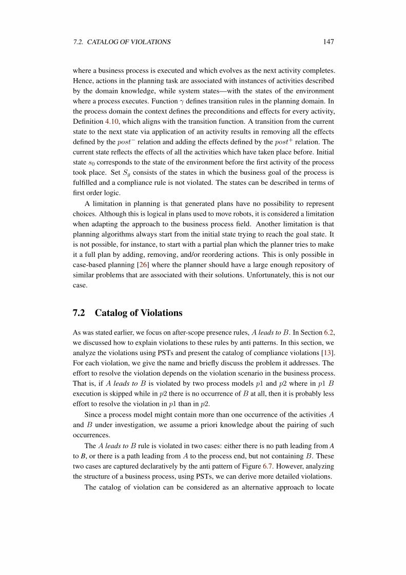
7.2. CATALOG OF VIOLATIONS 147
where a business process is executed and which evolves as the next activity completes.Hence, actions in the planning task are associated with instances of activities describedby the domain knowledge, while system states—with the states of the environmentwhere a process executes. Function γ defines transition rules in the planning domain. Inthe process domain the context defines the preconditions and effects for every activity,Definition 4.10, which aligns with the transition function. A transition from the currentstate to the next state via application of an activity results in removing all the effectsdefined by the post− relation and adding the effects defined by the post+ relation. Thecurrent state reflects the effects of all the activities which have taken place before. Initialstate s0 corresponds to the state of the environment before the first activity of the processtook place. Set Sg consists of the states in which the business goal of the process isfulfilled and a compliance rule is not violated. The states can be described in terms offirst order logic.
A limitation in planning is that generated plans have no possibility to representchoices. Although this is logical in plans used to move robots, it is considered a limitationwhen adapting the approach to the business process field. Another limitation is thatplanning algorithms always start from the initial state trying to reach the goal state. Itis not possible, for instance, to start with a partial plan which the planner tries to makeit a full plan by adding, removing, and/or reordering actions. This is only possible incase-based planning [26] where the planner should have a large enough repository ofsimilar problems that are associated with their solutions. Unfortunately, this is not ourcase.
7.2 Catalog of Violations
As was stated earlier, we focus on after-scope presence rules, A leads to B. In Section 6.2,we discussed how to explain violations to these rules by anti patterns. In this section, weanalyze the violations using PSTs and present the catalog of compliance violations [13].For each violation, we give the name and briefly discuss the problem it addresses. Theeffort to resolve the violation depends on the violation scenario in the business process.That is, if A leads to B is violated by two process models p1 and p2 where in p1 B
execution is skipped while in p2 there is no occurrence of B at all, then it is probably lesseffort to resolve the violation in p1 than in p2.
Since a process model might contain more than one occurrence of the activities Aand B under investigation, we assume a priori knowledge about the pairing of suchoccurrences.
The A leads to B rule is violated in two cases: either there is no path leading from Ato B, or there is a path leading from A to the process end, but not containing B. Thesetwo cases are captured declaratively by the anti pattern of Figure 6.7. However, analyzingthe structure of a business process, using PSTs, we can derive more detailed violations.
The catalog of violation can be considered as an alternative approach to locate
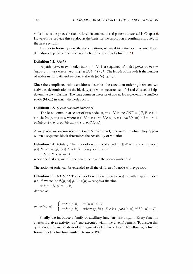
148 CHAPTER 7. RESOLUTION OF COMPLIANCE VIOLATION
violations on the process structure level, in contrast to anti patterns discussed in Chapter 6.However, we provide this catalog as the basis for the resolution algorithms discussed inthe next section.
In order to formally describe the violations, we need to define some terms. Thesedefinitions depend on the process structure tree given in Definition 7.1.
Definition 7.2. [Path]A path between two nodes n0, nk ∈ N , is a sequence of nodes path(n0, nk) =
(n0, n1, . . . , nk) where (ni, ni+1) ∈ E, 0 ≤ i < k. The length of the path is the numberof nodes in this path and we denote it with |path(n0, nk)|.
Since the compliance rule we address describes the execution ordering between twoactivities, determination of the block type in which occurrences of A and B execute helpsdetermine the violations. The least common ancestor of two nodes represents the smallestscope (block) in which the nodes occur.
Definition 7.3. [Least common ancestor]The least common ancestor of two nodes n,m ∈ N in the PST = (N,E, r, t) is
a node lca(n,m) = p where p ∈ N ∧ p ∈ path(r, n) ∧ p ∈ path(r,m) ∧ @p′ : p′ ∈path(r, n) ∧ p′ ∈ path(r,m) ∧ p ∈ path(r, p′).
Also, given two occurrences of A and B respectively, the order in which they appearwithin a sequence block determines the possibility of violation.
Definition 7.4. [Order] The order of execution of a node n ∈ N with respect to nodep ∈ N , where (p, n) ∈ E ∧ t(p) = seq is a function:
order : N ×N → N,where the first argument is the parent node and the second—its child.
The notion of order can be extended to all the children of a node with type seq.
Definition 7.5. [Order∗] The order of execution of a node n ∈ N with respect to nodep ∈ N where |path(p, n)| = 0 ∧ t(p) = seq is a function
order∗ : N ×N → N,defined as:
order∗(p, n) =
order(p, n) , if (p, n) ∈ E,
order(p, k) , where (p, k) ∈ E ∧ k ∈ path(p, n), if @(p, n) ∈ E.
Finally, we introduce a family of auxiliary functions exec<type>. Every functionchecks if a given activity is always executed within the given fragment. To answer thisquestion a recursive analysis of all fragment’s children is done. The following definitionformalizes this function family in terms of PST.
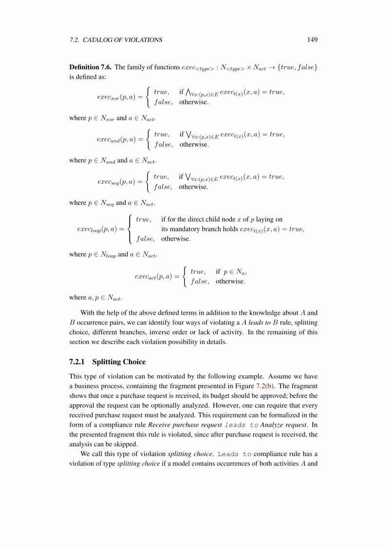
7.2. CATALOG OF VIOLATIONS 149
Definition 7.6. The family of functions exec<type> : N<type>×Nact → true, falseis defined as:
execxor(p, a) =
true, if
∀x:(p,x)∈E exect(x)(x, a) = true,
false, otherwise.
where p ∈ Nxor and a ∈ Nact.
execand(p, a) =
true, if
∀x:(p,x)∈E exect(x)(x, a) = true,
false, otherwise.
where p ∈ Nand and a ∈ Nact.
execseq(p, a) =
true, if
∀x:(p,x)∈E exect(x)(x, a) = true,
false, otherwise.
where p ∈ Nseq and a ∈ Nact.
execloop(p, a) =
true, if for the direct child node x of p laying on
its mandatory branch holds exect(x)(x, a) = true,
false, otherwise.
where p ∈ Nloop and a ∈ Nact.
execact(p, a) =
true, if p ∈ Na,
false, otherwise.
where a, p ∈ Nact.
With the help of the above defined terms in addition to the knowledge about A andB occurrence pairs, we can identify four ways of violating a A leads to B rule, splittingchoice, different branches, inverse order or lack of activity. In the remaining of thissection we describe each violation possibility in details.
7.2.1 Splitting Choice
This type of violation can be motivated by the following example. Assume we havea business process, containing the fragment presented in Figure 7.2(b). The fragmentshows that once a purchase request is received, its budget should be approved; before theapproval the request can be optionally analyzed. However, one can require that everyreceived purchase request must be analyzed. This requirement can be formalized in theform of a compliance rule Receive purchase request leads to Analyze request. Inthe presented fragment this rule is violated, since after purchase request is received, theanalysis can be skipped.
We call this type of violation splitting choice. Leads to compliance rule has aviolation of type splitting choice if a model contains occurrences of both activities A and
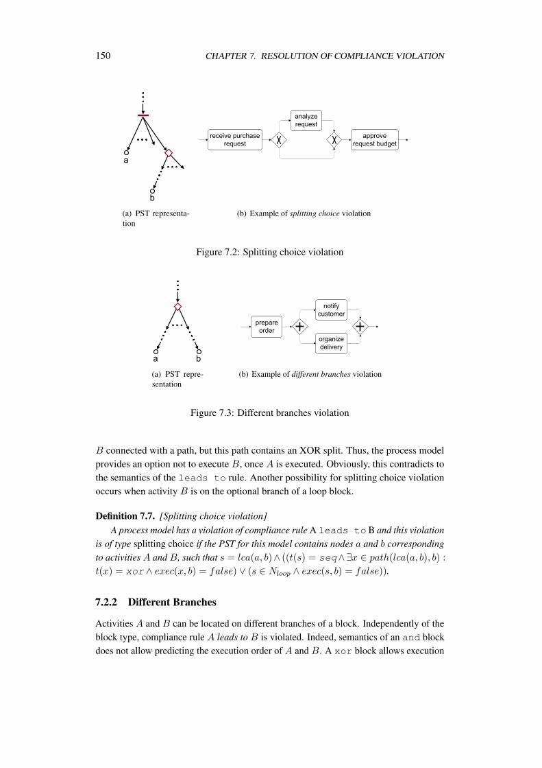
150 CHAPTER 7. RESOLUTION OF COMPLIANCE VIOLATION
(a) PST representa-tion
(b) Example of splitting choice violation
Figure 7.2: Splitting choice violation
(a) PST repre-sentation
(b) Example of different branches violation
Figure 7.3: Different branches violation
B connected with a path, but this path contains an XOR split. Thus, the process modelprovides an option not to execute B, once A is executed. Obviously, this contradicts tothe semantics of the leads to rule. Another possibility for splitting choice violationoccurs when activity B is on the optional branch of a loop block.
Definition 7.7. [Splitting choice violation]A process model has a violation of compliance rule A leads to B and this violation
is of type splitting choice if the PST for this model contains nodes a and b correspondingto activities A and B, such that s = lca(a, b)∧ ((t(s) = seq∧∃x ∈ path(lca(a, b), b) :
t(x) = xor ∧ exec(x, b) = false) ∨ (s ∈ Nloop ∧ exec(s, b) = false)).
7.2.2 Different Branches
Activities A and B can be located on different branches of a block. Independently of theblock type, compliance rule A leads to B is violated. Indeed, semantics of an and blockdoes not allow predicting the execution order of A and B. A xor block allows execution
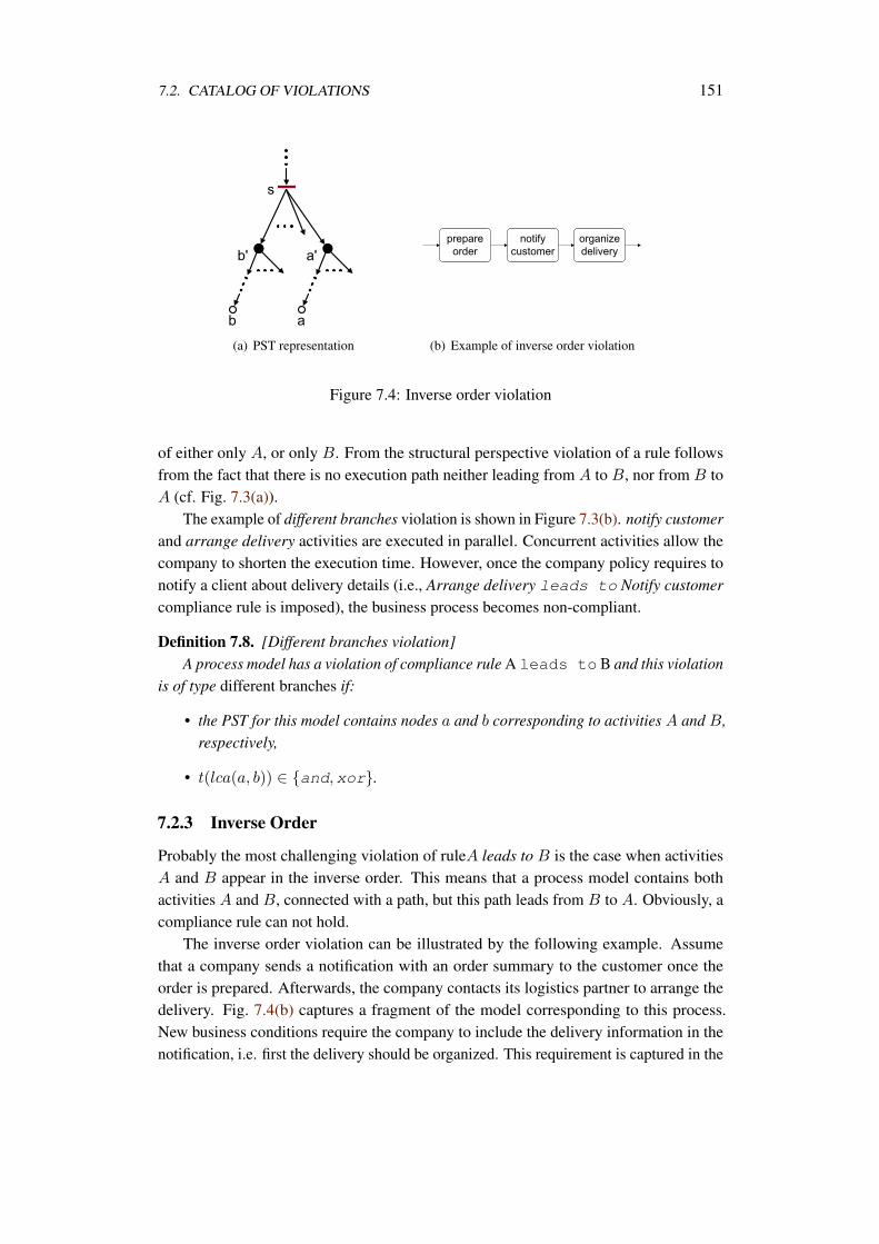
7.2. CATALOG OF VIOLATIONS 151
(a) PST representation (b) Example of inverse order violation
Figure 7.4: Inverse order violation
of either only A, or only B. From the structural perspective violation of a rule followsfrom the fact that there is no execution path neither leading from A to B, nor from B toA (cf. Fig. 7.3(a)).
The example of different branches violation is shown in Figure 7.3(b). notify customerand arrange delivery activities are executed in parallel. Concurrent activities allow thecompany to shorten the execution time. However, once the company policy requires tonotify a client about delivery details (i.e., Arrange delivery leads to Notify customercompliance rule is imposed), the business process becomes non-compliant.
Definition 7.8. [Different branches violation]A process model has a violation of compliance rule A leads to B and this violation
is of type different branches if:
• the PST for this model contains nodes a and b corresponding to activities A and B,respectively,
• t(lca(a, b)) ∈ and,xor.
7.2.3 Inverse Order
Probably the most challenging violation of ruleA leads to B is the case when activitiesA and B appear in the inverse order. This means that a process model contains bothactivities A and B, connected with a path, but this path leads from B to A. Obviously, acompliance rule can not hold.
The inverse order violation can be illustrated by the following example. Assumethat a company sends a notification with an order summary to the customer once theorder is prepared. Afterwards, the company contacts its logistics partner to arrange thedelivery. Fig. 7.4(b) captures a fragment of the model corresponding to this process.New business conditions require the company to include the delivery information in thenotification, i.e. first the delivery should be organized. This requirement is captured in the
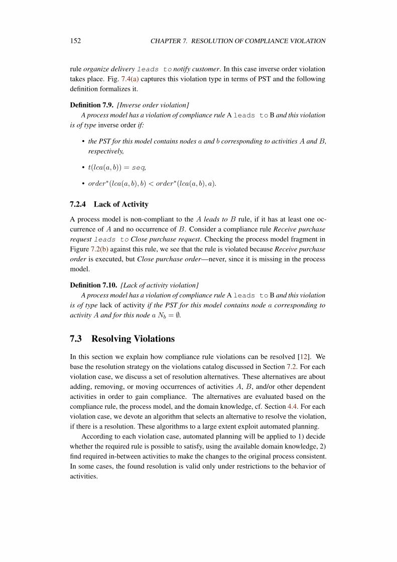
152 CHAPTER 7. RESOLUTION OF COMPLIANCE VIOLATION
rule organize delivery leads to notify customer. In this case inverse order violationtakes place. Fig. 7.4(a) captures this violation type in terms of PST and the followingdefinition formalizes it.
Definition 7.9. [Inverse order violation]A process model has a violation of compliance rule A leads to B and this violation
is of type inverse order if:
• the PST for this model contains nodes a and b corresponding to activities A and B,respectively,
• t(lca(a, b)) = seq,
• order∗(lca(a, b), b) < order∗(lca(a, b), a).
7.2.4 Lack of Activity
A process model is non-compliant to the A leads to B rule, if it has at least one oc-currence of A and no occurrence of B. Consider a compliance rule Receive purchaserequest leads to Close purchase request. Checking the process model fragment inFigure 7.2(b) against this rule, we see that the rule is violated because Receive purchaseorder is executed, but Close purchase order—never, since it is missing in the processmodel.
Definition 7.10. [Lack of activity violation]A process model has a violation of compliance rule A leads to B and this violation
is of type lack of activity if the PST for this model contains node a corresponding toactivity A and for this node a Nb = ∅.
7.3 Resolving Violations
In this section we explain how compliance rule violations can be resolved [12]. Webase the resolution strategy on the violations catalog discussed in Section 7.2. For eachviolation case, we discuss a set of resolution alternatives. These alternatives are aboutadding, removing, or moving occurrences of activities A, B, and/or other dependentactivities in order to gain compliance. The alternatives are evaluated based on thecompliance rule, the process model, and the domain knowledge, cf. Section 4.4. For eachviolation case, we devote an algorithm that selects an alternative to resolve the violation,if there is a resolution. These algorithms to a large extent exploit automated planning.
According to each violation case, automated planning will be applied to 1) decidewhether the required rule is possible to satisfy, using the available domain knowledge, 2)find required in-between activities to make the changes to the original process consistent.In some cases, the found resolution is valid only under restrictions to the behavior ofactivities.
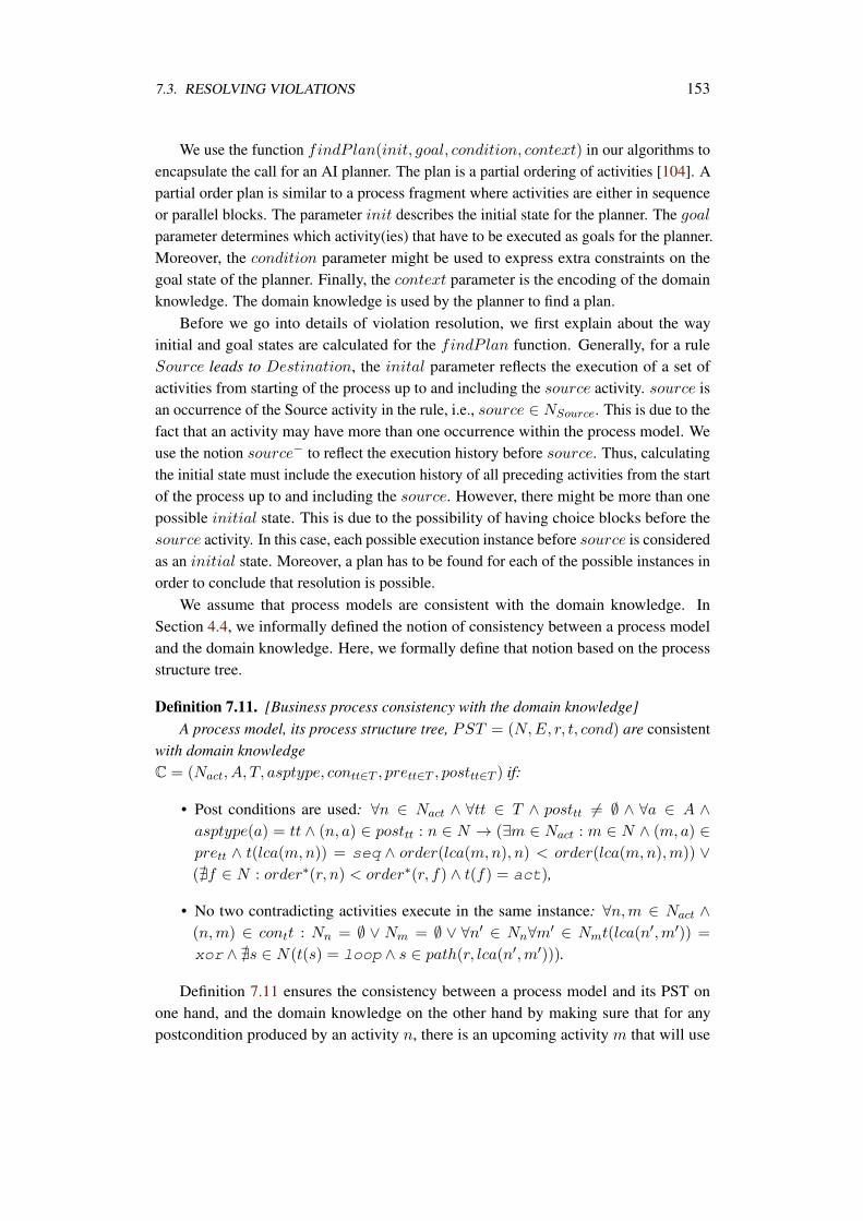
7.3. RESOLVING VIOLATIONS 153
We use the function findP lan(init, goal, condition, context) in our algorithms toencapsulate the call for an AI planner. The plan is a partial ordering of activities [104]. Apartial order plan is similar to a process fragment where activities are either in sequenceor parallel blocks. The parameter init describes the initial state for the planner. The goalparameter determines which activity(ies) that have to be executed as goals for the planner.Moreover, the condition parameter might be used to express extra constraints on thegoal state of the planner. Finally, the context parameter is the encoding of the domainknowledge. The domain knowledge is used by the planner to find a plan.
Before we go into details of violation resolution, we first explain about the wayinitial and goal states are calculated for the findP lan function. Generally, for a ruleSource leads to Destination, the inital parameter reflects the execution of a set ofactivities from starting of the process up to and including the source activity. source isan occurrence of the Source activity in the rule, i.e., source ∈ NSource. This is due to thefact that an activity may have more than one occurrence within the process model. Weuse the notion source− to reflect the execution history before source. Thus, calculatingthe initial state must include the execution history of all preceding activities from the startof the process up to and including the source. However, there might be more than onepossible initial state. This is due to the possibility of having choice blocks before thesource activity. In this case, each possible execution instance before source is consideredas an initial state. Moreover, a plan has to be found for each of the possible instances inorder to conclude that resolution is possible.
We assume that process models are consistent with the domain knowledge. InSection 4.4, we informally defined the notion of consistency between a process modeland the domain knowledge. Here, we formally define that notion based on the processstructure tree.
Definition 7.11. [Business process consistency with the domain knowledge]A process model, its process structure tree, PST = (N,E, r, t, cond) are consistent
with domain knowledgeC = (Nact, A, T, asptype, contt∈T , prett∈T , posttt∈T ) if:
• Post conditions are used: ∀n ∈ Nact ∧ ∀tt ∈ T ∧ posttt = ∅ ∧ ∀a ∈ A ∧asptype(a) = tt ∧ (n, a) ∈ posttt : n ∈ N → (∃m ∈ Nact : m ∈ N ∧ (m, a) ∈prett ∧ t(lca(m,n)) = seq ∧ order(lca(m,n), n) < order(lca(m,n),m)) ∨(@f ∈ N : order∗(r, n) < order∗(r, f) ∧ t(f) = act),
• No two contradicting activities execute in the same instance: ∀n,m ∈ Nact ∧(n,m) ∈ contt : Nn = ∅ ∨ Nm = ∅ ∨ ∀n′ ∈ Nn∀m′ ∈ Nmt(lca(n′,m′)) =
xor ∧ @s ∈ N(t(s) = loop ∧ s ∈ path(r, lca(n′,m′))).
Definition 7.11 ensures the consistency between a process model and its PST onone hand, and the domain knowledge on the other hand by making sure that for anypostcondition produced by an activity n, there is an upcoming activity m that will use
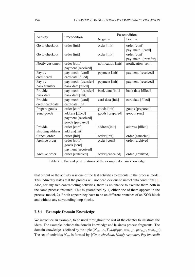
154 CHAPTER 7. RESOLUTION OF COMPLIANCE VIOLATION
Activity PreconditionPostcondition
Negative Positive
Go to checkout order [init] order [init] order [conf]pay. meth. [card]
Go to checkout order [init] order [init] order [conf]pay. meth. [transfer]
Notify customer order [conf] notification [init] notification [sent]payment [received]
Pay by pay. meth. [card] payment [init] payment [received]credit card card data [filled]Pay by pay. meth. [transfer] payment [init] payment [received]bank transfer bank data [filled]Provide pay. meth. [transfer] bank data [init] bank data [filled]bank data bank data [init]Provide pay. meth. [card] card data [init] card data [filled]credit card data card data [init]Prepare goods order [conf] goods [init] goods [prepared]Send goods address [filled] goods [prepared] goods [sent]
payment [received]goods [prepared]
Provide order [conf] address[init] address [filled]shipping address address[init]Cancel order order [init] order [init] order [canceled]Archive order order [conf] order [conf] order [archived]
goods [sent]payment [received]
Archive order order [canceled] order [canceled] order [archived]
Table 7.1: Pre and post relations of the example domain knowledge
that output or the activity n is one of the last activities to execute in the process model.This indirectly states that the process will not deadlock due to unmet data conditions [8].Also, for any two contradicting activities, there is no chance to execute them both inthe same process instance. This is guaranteed by 1) either one of them appears in theprocess model, 2) if both appear they have to be on different branches of an XOR blockand without any surrounding loop blocks.
7.3.1 Example Domain Knowledge
We introduce an example, to be used throughout the rest of the chapter to illustrate theideas. The example includes the domain knowledge and business process fragments. Thedomain knowledge is defined by the tuple (Nact, A, T, asptype, cont∈T , pret∈T , postt∈T ).The set of activities Nact is formed by Go to checkout, Notify customer, Pay by credit
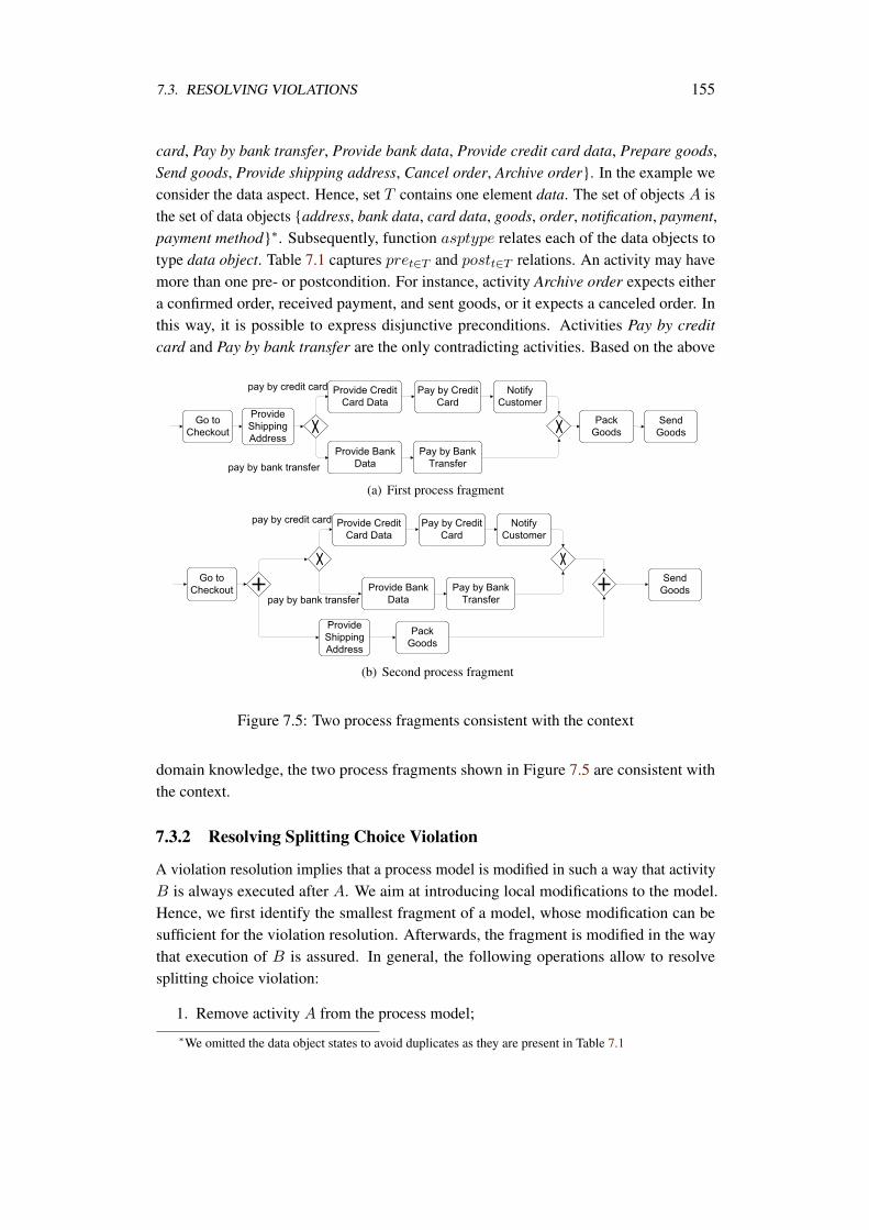
7.3. RESOLVING VIOLATIONS 155
card, Pay by bank transfer, Provide bank data, Provide credit card data, Prepare goods,Send goods, Provide shipping address, Cancel order, Archive order. In the example weconsider the data aspect. Hence, set T contains one element data. The set of objects A isthe set of data objects address, bank data, card data, goods, order, notification, payment,payment method∗. Subsequently, function asptype relates each of the data objects totype data object. Table 7.1 captures pret∈T and postt∈T relations. An activity may havemore than one pre- or postcondition. For instance, activity Archive order expects eithera confirmed order, received payment, and sent goods, or it expects a canceled order. Inthis way, it is possible to express disjunctive preconditions. Activities Pay by creditcard and Pay by bank transfer are the only contradicting activities. Based on the above
(a) First process fragment
(b) Second process fragment
Figure 7.5: Two process fragments consistent with the context
domain knowledge, the two process fragments shown in Figure 7.5 are consistent withthe context.
7.3.2 Resolving Splitting Choice Violation
A violation resolution implies that a process model is modified in such a way that activityB is always executed after A. We aim at introducing local modifications to the model.Hence, we first identify the smallest fragment of a model, whose modification can besufficient for the violation resolution. Afterwards, the fragment is modified in the waythat execution of B is assured. In general, the following operations allow to resolvesplitting choice violation:
1. Remove activity A from the process model;∗We omitted the data object states to avoid duplicates as they are present in Table 7.1
156 CHAPTER 7. RESOLUTION OF COMPLIANCE VIOLATION
2. Move activity A to the branch with B directly before activity B;
3. Add activity B to every branch in the choice block;
4. Remove all the branches which do not contain activity B;
5. Add activity B in between activity A and the choice block, directly after A;
6. Add activity B directly after the block;
7. Move activity B in between activity A and the choice block;
8. Move activity B directly after the choice block
Removing activity A from the process model would achieve vacuous compliance.However, apart from the inconsistency that might appear due to removing A, in thespecific case of splitting choice violation, the process logic already allows executing B
after A in some cases. Thus, we should look for a way to execute B in all cases. Thus,the first two alternatives are not suitable in this case.
Adding B to every branch where it is missing would solve the problem. In anyexclusive thread after A there is a chance to execute B. However, we have to make surethat there are no contradictions between B and other activities on branches lacking B, seeDefinition 7.11. If for a branch it is not possible to add B, the branch has to be removed,the fourth alternative. This could be justified by the fact that compliance requirements,in general, restrict the behavior of processes and they are supreme to the logic in theprocess. However, to guarantee consistency of the process, activities behavior, i.e., postconditions, has to be changed to guarantee that the process does not deadlock. That is, foreach branch to be removed, the branch condition has to be analyzed in order to identifyactivities which produce these conditions as effects. Afterwards, the behavior of theseactivities has to be modified in order to be sure that unused effects will not be produced.The role of automated resolution is to identify the conditions and activities respectively.Modifications to activity behavior are considered as a task of a human expert.
The remaining alternatives duplicate or move the activity B some point after A outof the choice block. Duplication might not be possible in every case. For instance, ifthe activity B is about payment, it is not possible to duplicate it. Also, duplication ormovement raises the issue of consistency again. In both cases, there is a chance that Bwill be in sequence with one of its contradicting activities on the other branches of thechoice block.
Algorithm 22 provides our approach to resolve this violation. Initially, a blockenclosing occurrences of activities A and B is sought, see line 1. If the enclosing block isa loop, the algorithm has to assure that B is executed after the loop. Automated planningattempts to construct a plan containing activity B. If the plan is constructed, it is insertedexactly after the loop block. Otherwise, the resolution cannot be performed. If the block isnot a loop, we seek inside it for a choice block containing b on its branch, line 9. For each
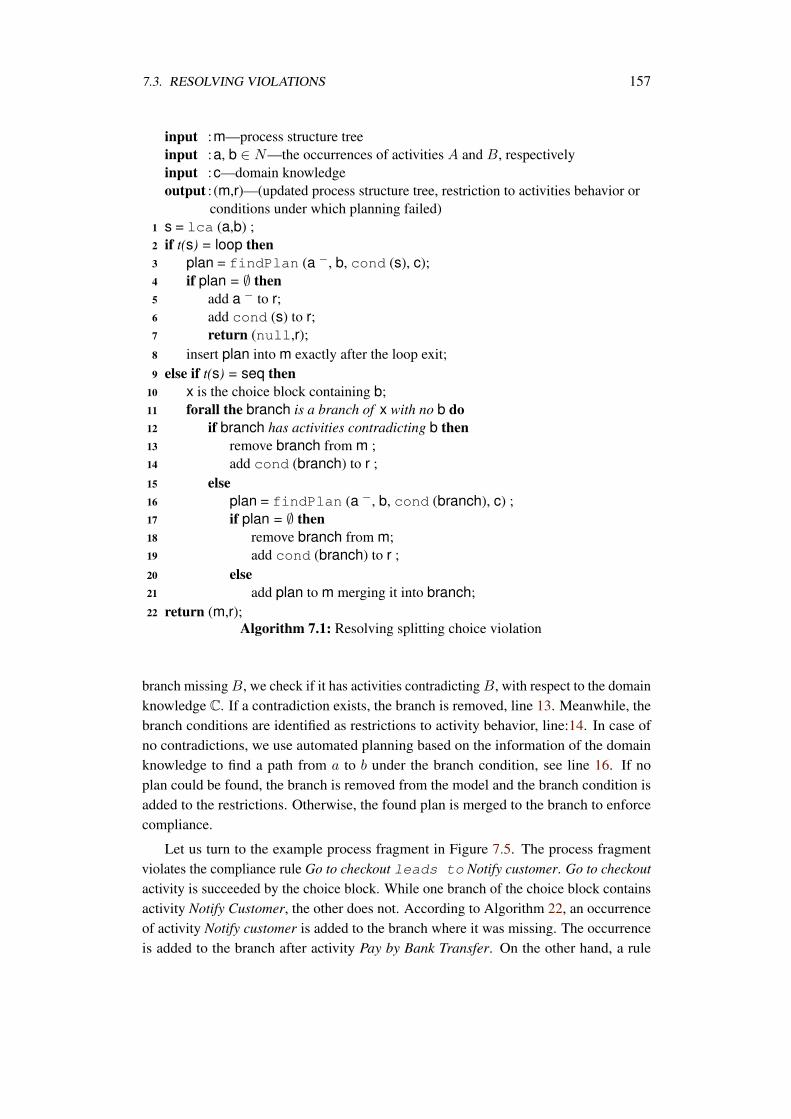
7.3. RESOLVING VIOLATIONS 157
input :m—process structure treeinput :a, b ∈ N—the occurrences of activities A and B, respectivelyinput :c—domain knowledgeoutput : (m,r)—(updated process structure tree, restriction to activities behavior or
conditions under which planning failed)1 s = lca (a,b) ;2 if t(s) = loop then3 plan = findPlan (a −, b, cond (s), c);4 if plan = ∅ then5 add a − to r;6 add cond (s) to r;7 return (null,r);8 insert plan into m exactly after the loop exit;9 else if t(s) = seq then
10 x is the choice block containing b;11 forall the branch is a branch of x with no b do12 if branch has activities contradicting b then13 remove branch from m ;14 add cond (branch) to r ;15 else16 plan = findPlan (a −, b, cond (branch), c) ;17 if plan = ∅ then18 remove branch from m;19 add cond (branch) to r ;20 else21 add plan to m merging it into branch;22 return (m,r);
Algorithm 7.1: Resolving splitting choice violation
branch missing B, we check if it has activities contradicting B, with respect to the domainknowledge C. If a contradiction exists, the branch is removed, line 13. Meanwhile, thebranch conditions are identified as restrictions to activity behavior, line:14. In case ofno contradictions, we use automated planning based on the information of the domainknowledge to find a path from a to b under the branch condition, see line 16. If noplan could be found, the branch is removed from the model and the branch condition isadded to the restrictions. Otherwise, the found plan is merged to the branch to enforcecompliance.
Let us turn to the example process fragment in Figure 7.5. The process fragmentviolates the compliance rule Go to checkout leads to Notify customer. Go to checkoutactivity is succeeded by the choice block. While one branch of the choice block containsactivity Notify Customer, the other does not. According to Algorithm 22, an occurrenceof activity Notify customer is added to the branch where it was missing. The occurrenceis added to the branch after activity Pay by Bank Transfer. On the other hand, a rule
158 CHAPTER 7. RESOLUTION OF COMPLIANCE VIOLATION
Go to checkout leads to Pay by credit card is also violated. However, to resolvethis violation using Algorithm 22, the lower branch has to be removed. In this case, thebranch condition payment method[transfer] is identified as a restriction. Thatis, the resulting process is consistent only in the case that the postcondition paymentmethod[transfer] of activity Go to checkout is removed.
7.3.3 Resolving Different Branches Violation
As stated earlier, a violation of this type takes place if the two activities are allocatedon different branches of a block, independent of a block type, i.e., either an XOR or anAND block. However, the resolution strategy varies depending on the block type. Thefollowing operations allow to resolve the violation:
1. Remove activity A from the process model;
2. Add activity B to the branch with A directly after activity A (for xor block);
3. Move activity B directly after the block (for and block);
4. Move activity A directly before block (for and block)
In case that activity A and B are on different branches of an XOR block, removing A
from the process solves the problem. But, we have to remove the whole branch whereA belongs, to be sure that no remaining activities without unmet inputs. However, asdiscussed earlier, removing a branch necessitates making restrictions to preceding activitybehavior. Otherwise, the process would deadlock due to unmet inputs.
The second alternative is to add B after A. This is possible in case there are nocontradicting activities to B on that branch. However, we handle these situations as alack of activity as we will show later. If this succeeds, it is preferable to the situation ofremoving A from the process model.
In case of an AND block, the resolution strategy aims at sequentializing A and B.To achieve the sequential execution of A and B, we move an occurrence of B from ablock branch to the position exactly after the block. However, such a manipulation withan occurrence of B might introduce inconsistencies into the process model: there mightbe activities on the branch expecting B in the initial place. Hence, we move not only anoccurrence of B, but the set of activities succeeding B on the branch and depending onB. An alternative strategy is to move A, together with preceding activities on which A
depends, exactly before the block. The preference to one of these strategies can be givenbasing on the number of activities to be moved.
Algorithm 18 summarizes the resolution for different branches violation. First, thetype of block is identified, line 1. In case of XOR block, the algorithm checks whether itis possible to add a new occurrence of B after A, by calling the lack of activity resolutionalgorithm. If there is a solution, the resulting plan is merged with the process model.Otherwise, the branch containing A is removed. In this case, the branch condition is
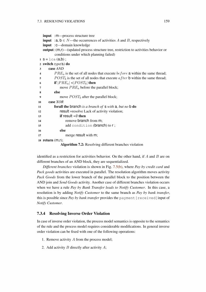
7.3. RESOLVING VIOLATIONS 159
input :m—process structure treeinput :a, b ∈ N—the occurrences of activities A and B, respectivelyinput :c—domain knowledgeoutput : (m,r)—(updated process structure tree, restriction to activities behavior or
conditions under which planning failed)1 s = lca (a,b) ;2 switch type(s) do3 case AND4 PREa is the set of all nodes that execute before a within the same thread;5 POSTb is the set of all nodes that execute after b within the same thread;6 if |PREa| <|POSTb| then7 move PREa before the parallel block;8 else9 move POSTb after the parallel block;
10 case XOR11 forall the branch is a branch of s with a, but no b do12 result =resolve Lack of activity violation;13 if result =∅ then14 remove branch from m;15 add condition (branch) to r ;16 else17 merge result with m;18 return (m,r);
Algorithm 7.2: Resolving different branches violation
identified as a restriction for activities behavior. On the other hand, if A and B are ondifferent branches of an AND block, they are sequentialized.
Different branches violation is shown in Fig. 7.5(b), where Pay by credit card andPack goods activities are executed in parallel. The resolution algorithm moves activityPack Goods from the lower branch of the parallel block to the position between theAND join and Send Goods activity. Another case of different branches violation occurswhen we have a rule Pay by Bank Transfer leads to Notify Customer. In this case, aresolution is by adding Notify Customer to the same branch as Pay by bank transfer,this is possible since Pay by bank transfer provides the payment[received]input ofNotify Customer.
7.3.4 Resolving Inverse Order Violation
In case of inverse order violation, the process model semantics is opposite to the semanticsof the rule and the process model requires considerable modifications. In general inverseorder violation can be fixed with one of the following operations:
1. Remove activity A from the process model;
2. Add activity B directly after activity A;
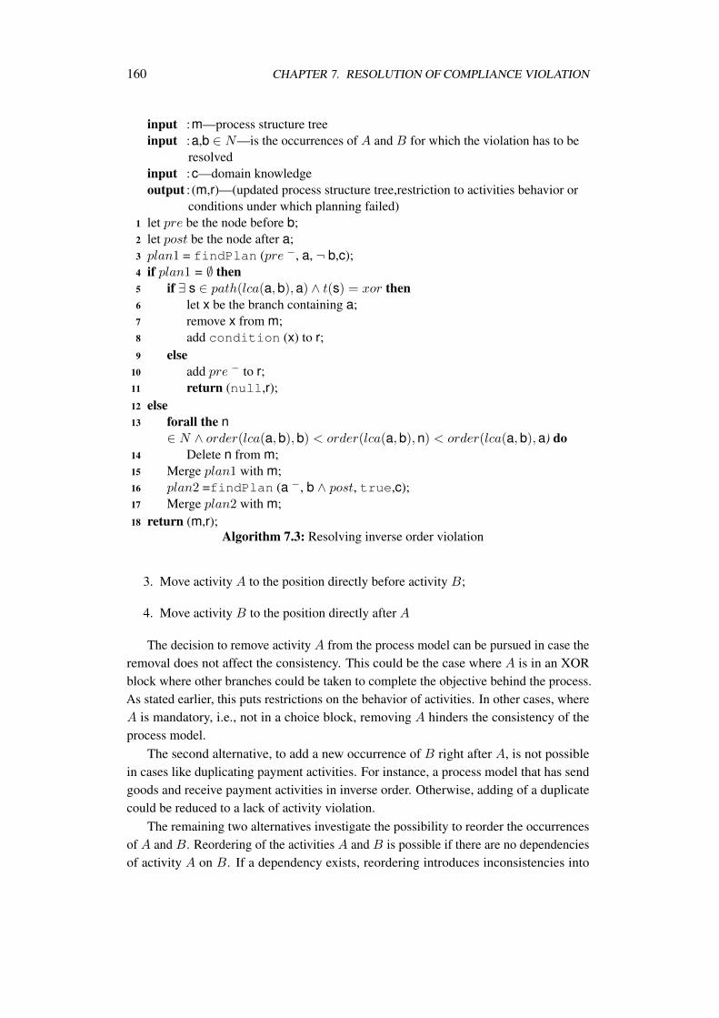
160 CHAPTER 7. RESOLUTION OF COMPLIANCE VIOLATION
input :m—process structure treeinput :a,b ∈ N—is the occurrences of A and B for which the violation has to be
resolvedinput :c—domain knowledgeoutput : (m,r)—(updated process structure tree,restriction to activities behavior or
conditions under which planning failed)1 let pre be the node before b;2 let post be the node after a;3 plan1 = findPlan (pre −, a, ¬ b,c);4 if plan1 = ∅ then5 if ∃ s ∈ path(lca(a,b),a) ∧ t(s) = xor then6 let x be the branch containing a;7 remove x from m;8 add condition (x) to r;9 else
10 add pre − to r;11 return (null,r);12 else13 forall the n
∈ N ∧ order(lca(a,b),b) < order(lca(a,b),n) < order(lca(a,b),a) do14 Delete n from m;15 Merge plan1 with m;16 plan2 =findPlan (a −, b ∧ post, true,c);17 Merge plan2 with m;18 return (m,r);
Algorithm 7.3: Resolving inverse order violation
3. Move activity A to the position directly before activity B;
4. Move activity B to the position directly after A
The decision to remove activity A from the process model can be pursued in case theremoval does not affect the consistency. This could be the case where A is in an XORblock where other branches could be taken to complete the objective behind the process.As stated earlier, this puts restrictions on the behavior of activities. In other cases, whereA is mandatory, i.e., not in a choice block, removing A hinders the consistency of theprocess model.
The second alternative, to add a new occurrence of B right after A, is not possiblein cases like duplicating payment activities. For instance, a process model that has sendgoods and receive payment activities in inverse order. Otherwise, adding of a duplicatecould be reduced to a lack of activity violation.
The remaining two alternatives investigate the possibility to reorder the occurrencesof A and B. Reordering of the activities A and B is possible if there are no dependenciesof activity A on B. If a dependency exists, reordering introduces inconsistencies into
7.3. RESOLVING VIOLATIONS 161
the process model. To check whether reordering is possible, we attempt to construct amodel fragment from the process start to the point where A is executed. To come up withthis fragment, we construct a plan. In contrast to the initial model, activity B should notappear in this plan. The initial state of the planning task reflects the process state directlybefore activity B is executed. The goal state describes that activity A must be executed.If the planner comes up with the plan, the reordering is possible. Otherwise, there is nochance to reorder since actually A depends on the result of B.
Once reordering turns out to be possible, the resulting plan must be complementedto assure execution of B. The second planning task’s initial state is the first plan’s goalstate. The new goal state describes the process state directly after an execution of Bin the initial process. The two plans are inserted into the model. The model is free ofcontradictions and inconsistencies, since we just reordered activities, the resolution iscompleted.
Algorithm 18 summarizes our approach to resolve inverse order violation. First ittries to reorder A and B. If this is not possible and A is in a choice block. It removes Aand identifies restrictions to activity behavior that are necessary to ensure a consistentresult. On the other hand, if A is mandatory, the algorithm fails.
The inverse order violation can be illustrated by the process fragment in Fig. 7.5(a),where the company sends a notification with an order summary to a customer. Afterwards,the company contacts its logistics partner to pack and send goods. New business condi-tions might require the company to include the delivery information in the notification,i.e., first the goods should be packed. This requirement is captured in the rule Pack goodsleads to Notify customer rule. This violation is of type inverse order.
In the example of Pack goods leads to Notify customer rule violation the resolu-tion strategy moves the occurrence of Notify Customer activity to the position after PackGoods activity.
7.3.5 Lack of Activity
A process model contains a violation to A leads to B of type lack of activity, if itcontains at least one occurrence of A and no occurrence of B. The following operationsallow to resolve lack of activity violation:
1. Remove activity A from the process model;
2. Add activity B directly before A
Consider a compliance rule Go to checkout leads to Archive order. Checking theprocess model fragment in Fig. 7.5(a) against this rule, we see that this rule is violated,since Archive order is missing in that fragment.
To resolve a violation of this type we introduce an occurrence of B into the processmodel exactly after an occurrence of A. If the process model does not contain activitiescontradicting to B, we construct a plan using findPlan(A, B, true, context). The plan
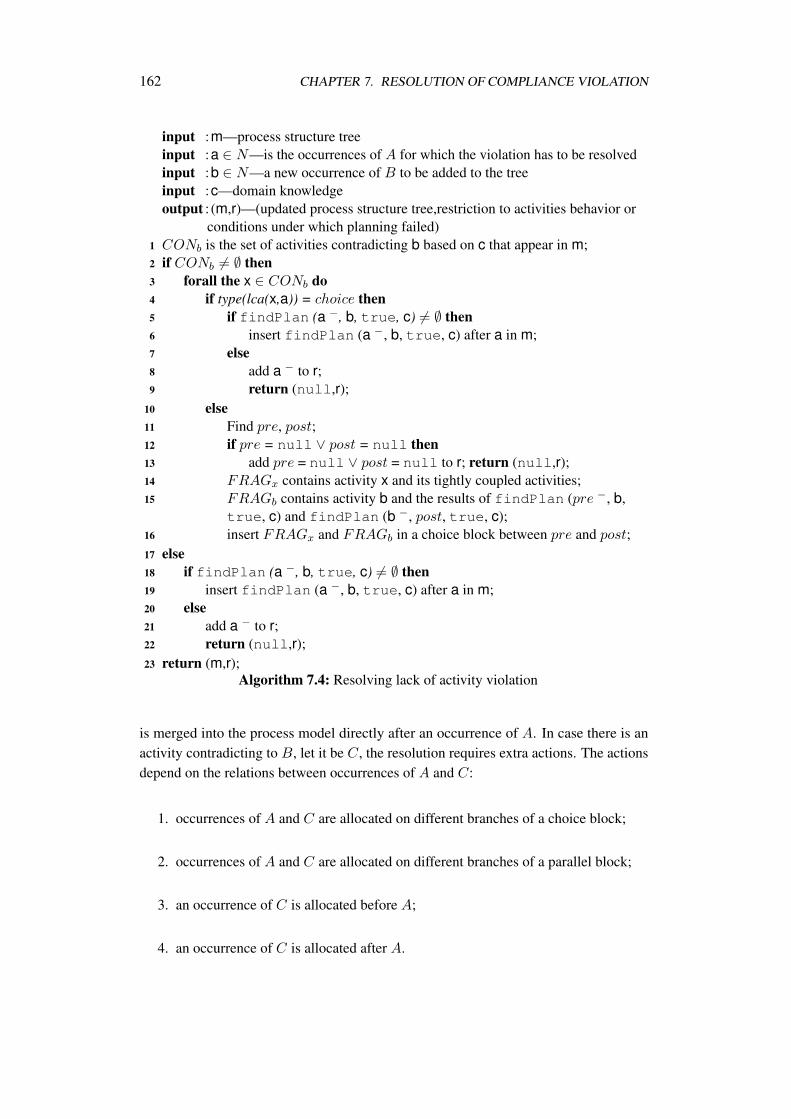
162 CHAPTER 7. RESOLUTION OF COMPLIANCE VIOLATION
input :m—process structure treeinput :a ∈ N—is the occurrences of A for which the violation has to be resolvedinput :b ∈ N—a new occurrence of B to be added to the treeinput :c—domain knowledgeoutput : (m,r)—(updated process structure tree,restriction to activities behavior or
conditions under which planning failed)1 CONb is the set of activities contradicting b based on c that appear in m;2 if CONb = ∅ then3 forall the x ∈ CONb do4 if type(lca(x,a)) = choice then5 if findPlan (a −, b, true, c) = ∅ then6 insert findPlan (a −, b, true, c) after a in m;7 else8 add a − to r;9 return (null,r);
10 else11 Find pre, post;12 if pre = null ∨ post = null then13 add pre = null ∨ post = null to r; return (null,r);14 FRAGx contains activity x and its tightly coupled activities;15 FRAGb contains activity b and the results of findPlan (pre −, b,
true, c) and findPlan (b −, post, true, c);16 insert FRAGx and FRAGb in a choice block between pre and post;17 else18 if findPlan (a −, b, true, c) = ∅ then19 insert findPlan (a −, b, true, c) after a in m;20 else21 add a − to r;22 return (null,r);23 return (m,r);
Algorithm 7.4: Resolving lack of activity violation
is merged into the process model directly after an occurrence of A. In case there is anactivity contradicting to B, let it be C, the resolution requires extra actions. The actionsdepend on the relations between occurrences of A and C:
1. occurrences of A and C are allocated on different branches of a choice block;
2. occurrences of A and C are allocated on different branches of a parallel block;
3. an occurrence of C is allocated before A;
4. an occurrence of C is allocated after A.
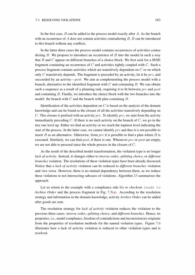
7.3. RESOLVING VIOLATIONS 163
In the first case, B can be added to the process model exactly after A. As the branchwith an occurrence of A does not contain activities contradicting B, B can be introducedto this branch without any conflicts.
In the latter three cases the process model contains occurrences of activities contra-dicting B. We propose to introduce an occurrence of B into the model in such a waythat B and C appear on different branches of a choice block. We first seek for a SESEfragment containing an occurrence of C and activities tightly coupled with C. Such aprocess fragment contains activities which are transitively dependent on C or on whichonly C transitively depends. The fragment is preceded by an activity, let it be pre, andsucceeded by an activity—post. We aim at complementing the process model with abranch, alternative to the identified fragment with C and containing B. We can obtainsuch a sequence as a result of a planning task, requiring it to fit between pre and post
and containing B. Finally, we introduce the choice block with the two branches into themodel: the branch with C and the branch with plan containing B.
Identification of the activities dependent on C is based on the analysis of the domainknowledge and can be found as the closure of all the activities transitively depending onC. This closure is prefixed with an activity pre. To identify pre, we start from the activityimmediately preceding C. If there is no such activity on the branch of C, we go in thetree one level up. Either we find an activity or we reach the topmost level indicating thestart of the process. In the latter case, we cannot identify pre and thus it is not possible toinsert B as an alternative. Otherwise, from pre it is possible to find a plan where B isexecuted. Similarly, we can find post, if there is one. Whenever pre or post are empty,we are not able to proceed since the whole process in the closure of C.
As the result of the described model transformation, the violation type is no longerlack of activity. Instead, it changes either to inverse order, splitting choice, or differentbranches violation. The resolutions of these violation types have been already discussed.Notice that a lack of activity violation can be reduced to different branches violationand vice versa. However, there is no mutual dependency between them, as we reducethese violations to not intersecting subcases of violations. Algorithm 23 summarizes theapproach.
Let us return to the example with a compliance rule Go to checkout leads to
Archive Order and the process fragment in Fig. 7.5(a). According to the resolutionstrategy and information in the domain knowledge, activity Archive Order can be addedafter goods are sent.
The resolution strategy for lack of activity violation reduces the violation to theprevious three cases: inverse order, splitting choice, and different branches. Hence, itsproperties, i.e., model compliance, freedom of contradictions and inconsistencies originatefrom the properties of resolution methods for the named violation types. Figure 7.6illustrates how a lack of activity violation is reduced to other violation types and isresolved.
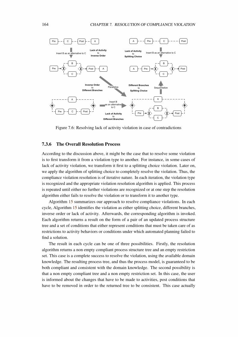
164 CHAPTER 7. RESOLUTION OF COMPLIANCE VIOLATION
Figure 7.6: Resolving lack of activity violation in case of contradictions
7.3.6 The Overall Resolution Process
According to the discussion above, it might be the case that to resolve some violationis to first transform it from a violation type to another. For instance, in some cases oflack of activity violation, we transform it first to a splitting choice violation. Later on,we apply the algorithm of splitting choice to completely resolve the violation. Thus, thecompliance violation resolution is of iterative nature. In each iteration, the violation typeis recognized and the appropriate violation resolution algorithm is applied. This processis repeated until either no further violations are recognized or at one step the resolutionalgorithm either fails to resolve the violation or to transform it to another type.
Algorithm 15 summarizes our approach to resolve compliance violations. In eachcycle, Algorithm 15 identifies the violation as either splitting choice, different branches,inverse order or lack of activity. Afterwards, the corresponding algorithm is invoked.Each algorithm returns a result on the form of a pair of an updated process structuretree and a set of conditions that either represent conditions that must be taken care of asrestrictions to activity behaviors or conditions under which automated planning failed tofind a solution.
The result in each cycle can be one of three possibilities. Firstly, the resolutionalgorithm returns a non empty compliant process structure tree and an empty restrictionset. This case is a complete success to resolve the violation, using the available domainknowledge. The resulting process tree, and thus the process model, is guaranteed to beboth compliant and consistent with the domain knowledge. The second possibility isthat a non empty compliant tree and a non empty restriction set. In this case, the useris informed about the changes that have to be made to activities, post conditions thathave to be removed in order to the returned tree to be consistent. This case actually
7.4. DIRECTIONS TO RESOLVE VIOLATIONS TO OTHER PATTERNS 165
input :m—process structure treeinput :A Leads to Binput :c—domain knowledgeoutput : (m,r)—(updated process structure tree, restrictions or conditions under
which planning failed)1 violation=getViolationType (m,A,B);2 while violation = none do3 switch violation do4 case Splitting Choice5 (m, r) = resolveSplittingChoice(m,a,b, c);6 case Different Branches7 (m,r)=resolveDifferentBranches (m,a,b,c);8 case Inverse Order9 (m,r)=resolveInverseOrder (m,a,b,c);
10 case Lack of Activity11 (m,r)=resolveLackActivity (m,a,b,c);12 if m =null ∨ r = null then13 return (m,r);14 violation=getViolationType (m,A,B);15 return (m,r);
Algorithm 7.5: Compliance violation resolution
indicates some sort of contradiction between the logic implied by the compliance ruleand the current understanding of the business domain. With this warning about possiblecontradictions, users might change their perception of the domain due to new compliancerequirements or they can identify that there is a problem within the compliance rule itself.The third and last possibility of the resolution is an empty tree and a non-empty restrictionset. In this case, the restriction set reports the conditions under which planning failed. Inthis case, there is a clear contradiction between what the common understanding of thebusiness domain is and what is stated in the compliance rule. To overcome this obstacle,the user has to make major changes to the domain knowledge or to the compliance rule.
7.4 Directions to Resolve Violations to Other Patterns
So far, we focused on resolving violations to the after-scope presence pattern. In this sec-tion, we give an overview on how to approach the resolution of other patterns’ violations.
The global-scope presence pattern is similar to the after-scope pattern, where anactivity B has to be the response for the start of the process. The chances for violationare either splitting choice or lack of activity. Algorithms 22, 23 can be applied to resolvethese violations.
The before-scope presence, A precedes B, violations are symmetric to the after-scopepresence violations. Rather, the emphasis will be on the side of the activity A. Thewhole catalog of violation is applicable, with redefinition on the activity A side. However,
166 CHAPTER 7. RESOLUTION OF COMPLIANCE VIOLATION
to enable automated planning, the pre and post conditions of activities, in the domainknowledge, is reversed. After a plan is found, it is reversed again to have it in the originalflow.
A violation to an absence pattern, e.g., after-scope absence, occurs when there isa chance to execute A and B in parallel or in sequence, where A executes first. Toresolve this violation, we might check first if B is optional in the process model. Ifthis is the case, the whole XOR branch is removed. Following the discussion aboutAlgorithm 22, we can argue that this solution results in a consistent process model, undercertain restrictions. On the other hand, if B is mandatory, similar to the approach ofresolving lack of activity violation, we try to identify the scope of effect of B. Usingautomated planning, we try to find a plan where B is avoided. Otherwise, it is not possibleto resolve the violation automatically. Similar strategy could be used to handle violationsto other absence patterns.
Resolving violations to conditional patterns is straightforward. Conditions can bereflected directly in the initial and/or goal states of the required plan. However, mergingthe resulting plan with the original process must explicitly add a choice block, whosecondition is the same as the conditional rule, where the missing activities are added.
7.5 Discussion
A violation resolution implies that a process model structure is changed. To control modelstructural modifications we employ the concept of SESE fragments. As a consequence,the approach is limited to process models, which are block-structured. To neglectthis limitation advanced decomposition techniques, as described in [110, 108], can beemployed. However, these approaches do not promise to reveal structure in unstructuredparts within processes. Thus, in case of unstructured parts of the process, user attention isdrawn to that problem and it is on her side to manually resolve the violation.
Besides restoring compliance in business process models, another objective is tokeep the modified process models operational. To maintain operation-ability, automatedplanning was employed to 1) identify whether it is possible to restore compliance 2) findsequences of activities that have to be added in order to restore compliance. For the firstcase, if it is not possible under the given compliance rule to find a sequence of activitiesexecution that restores compliance, it is indicated to the user that there is an inherentcontradiction between the compliance rule and the general domain knowledge. For thesecond case, if a sequence of activities is found, it is merged with the process model tomake it both compliant and operational.
Although the changes introduced by the resolution algorithms result in consistent andcompliant processes models, an updated model might look unnatural for a human reader.For instance, sequentialization of two branches in case of different branches violation,leaves only one branch in the parallel block. Thus, a resulting process model needs to berefactored to develop a naturally looking process model. Process refactoring techniques

7.5. DISCUSSION 167
proposed in [147] can be applied.

Chapter 8
Implementation
Developing prototypes is currently an important step for research in general and for thebusiness process management community in specific. With an implementation, conceptscan be better communicated with audience and more valuable feedback could be gained.Moreover, testing with real world scenarios refines and reshapes concepts.
This chapter describes a prototypical implementation of the contributions discussedin Chapters 4, 5 and 6. We describe an architecture where the user models compliancerules as BPMN-Q queries and at the end receives a decision about every relevant processwhether it is compliant or not. Moreover, in case of non compliance the user is informedabout parts of the process that cause the violation. Thus, we have a set of components torealize a compliance checking scenario. These components are
• Compliance rules editor (BPMN-Q query editor),
• BPMN-Q query processor,
• Business process model editor,
• Business process model repository,
• Mapping of process models to Petri nets,
• Petri net state space generation,
• Model checker.
Obviously, the objective is to keep implementing new components as minimal aspossible. We had to implement the query processor as it is one of the core contributionsof this thesis. Moreover, we had to implement an editor for creating compliance rulesas queries. However, we needed to access a repository of process models to query andto check for compliance. For the process model to Petri net mapping, we followed the
169
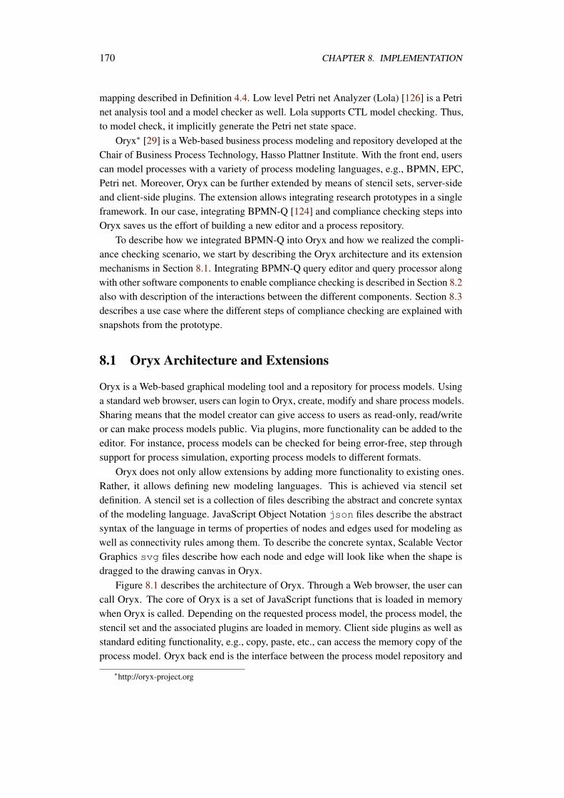
170 CHAPTER 8. IMPLEMENTATION
mapping described in Definition 4.4. Low level Petri net Analyzer (Lola) [126] is a Petrinet analysis tool and a model checker as well. Lola supports CTL model checking. Thus,to model check, it implicitly generate the Petri net state space.
Oryx∗ [29] is a Web-based business process modeling and repository developed at theChair of Business Process Technology, Hasso Plattner Institute. With the front end, userscan model processes with a variety of process modeling languages, e.g., BPMN, EPC,Petri net. Moreover, Oryx can be further extended by means of stencil sets, server-sideand client-side plugins. The extension allows integrating research prototypes in a singleframework. In our case, integrating BPMN-Q [124] and compliance checking steps intoOryx saves us the effort of building a new editor and a process repository.
To describe how we integrated BPMN-Q into Oryx and how we realized the compli-ance checking scenario, we start by describing the Oryx architecture and its extensionmechanisms in Section 8.1. Integrating BPMN-Q query editor and query processor alongwith other software components to enable compliance checking is described in Section 8.2also with description of the interactions between the different components. Section 8.3describes a use case where the different steps of compliance checking are explained withsnapshots from the prototype.
8.1 Oryx Architecture and Extensions
Oryx is a Web-based graphical modeling tool and a repository for process models. Usinga standard web browser, users can login to Oryx, create, modify and share process models.Sharing means that the model creator can give access to users as read-only, read/writeor can make process models public. Via plugins, more functionality can be added to theeditor. For instance, process models can be checked for being error-free, step throughsupport for process simulation, exporting process models to different formats.
Oryx does not only allow extensions by adding more functionality to existing ones.Rather, it allows defining new modeling languages. This is achieved via stencil setdefinition. A stencil set is a collection of files describing the abstract and concrete syntaxof the modeling language. JavaScript Object Notation json files describe the abstractsyntax of the language in terms of properties of nodes and edges used for modeling aswell as connectivity rules among them. To describe the concrete syntax, Scalable VectorGraphics svg files describe how each node and edge will look like when the shape isdragged to the drawing canvas in Oryx.
Figure 8.1 describes the architecture of Oryx. Through a Web browser, the user cancall Oryx. The core of Oryx is a set of JavaScript functions that is loaded in memorywhen Oryx is called. Depending on the requested process model, the process model, thestencil set and the associated plugins are loaded in memory. Client side plugins as well asstandard editing functionality, e.g., copy, paste, etc., can access the memory copy of theprocess model. Oryx back end is the interface between the process model repository and
∗http://oryx-project.org
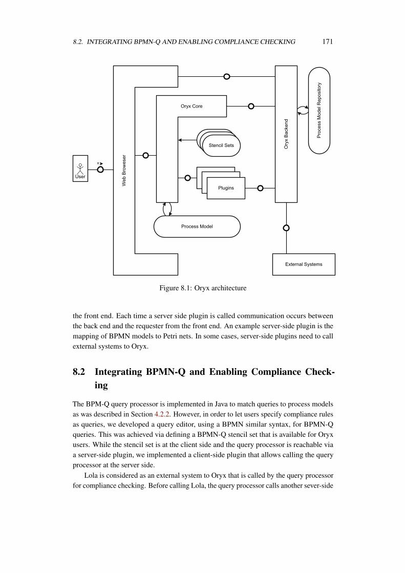
8.2. INTEGRATING BPMN-Q AND ENABLING COMPLIANCE CHECKING 171
Figure 8.1: Oryx architecture
the front end. Each time a server side plugin is called communication occurs betweenthe back end and the requester from the front end. An example server-side plugin is themapping of BPMN models to Petri nets. In some cases, server-side plugins need to callexternal systems to Oryx.
8.2 Integrating BPMN-Q and Enabling Compliance Check-ing
The BPM-Q query processor is implemented in Java to match queries to process modelsas was described in Section 4.2.2. However, in order to let users specify compliance rulesas queries, we developed a query editor, using a BPMN similar syntax, for BPMN-Qqueries. This was achieved via defining a BPMN-Q stencil set that is available for Oryxusers. While the stencil set is at the client side and the query processor is reachable viaa server-side plugin, we implemented a client-side plugin that allows calling the queryprocessor at the server side.
Lola is considered as an external system to Oryx that is called by the query processorfor compliance checking. Before calling Lola, the query processor calls another sever-side
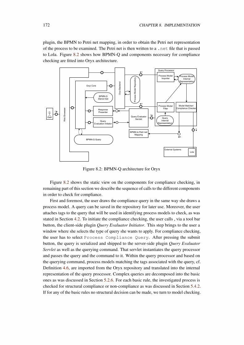
172 CHAPTER 8. IMPLEMENTATION
plugin, the BPMN to Petri net mapping, in order to obtain the Petri net representationof the process to be examined. The Petri net is then written to a .net file that is passedto Lola. Figure 8.2 shows how BPMN-Q and components necessary for compliancechecking are fitted into Oryx architecture.
Figure 8.2: BPMN-Q architecture for Oryx
Figure 8.2 shows the static view on the components for compliance checking, inremaining part of this section we describe the sequence of calls to the different componentsin order to check for compliance.
First and foremost, the user draws the compliance query in the same way she draws aprocess model. A query can be saved in the repository for later use. Moreover, the userattaches tags to the query that will be used in identifying process models to check, as wasstated in Section 4.2. To initiate the compliance checking, the user calls , via a tool barbutton, the client-side plugin Query Evaluator Initiator. This step brings to the user awindow where she selects the type of query she wants to apply. For compliance checking,the user has to select Process Compliance Query. After pressing the submitbutton, the query is serialized and shipped to the server-side plugin Query EvaluatorServlet as well as the querying command. That servlet instantiates the query processorand passes the query and the command to it. Within the query processor and based onthe querying command, process models matching the tags associated with the query, cf.Definition 4.6, are imported from the Oryx repository and translated into the internalrepresentation of the query processor. Complex queries are decomposed into the basicones as was discussed in Section 5.2.6. For each basic rule, the investigated process ischecked for structural compliance or non-compliance as was discussed in Section 5.4.2.If for any of the basic rules no structural decision can be made, we turn to model checking.
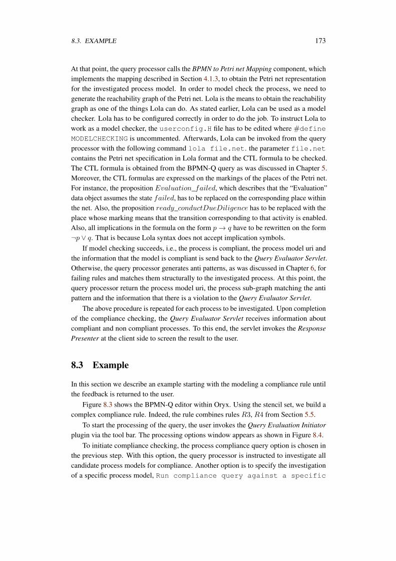
8.3. EXAMPLE 173
At that point, the query processor calls the BPMN to Petri net Mapping component, whichimplements the mapping described in Section 4.1.3, to obtain the Petri net representationfor the investigated process model. In order to model check the process, we need togenerate the reachability graph of the Petri net. Lola is the means to obtain the reachabilitygraph as one of the things Lola can do. As stated earlier, Lola can be used as a modelchecker. Lola has to be configured correctly in order to do the job. To instruct Lola towork as a model checker, the userconfig.H file has to be edited where #define
MODELCHECKING is uncommented. Afterwards, Lola can be invoked from the queryprocessor with the following command lola file.net. the parameter file.netcontains the Petri net specification in Lola format and the CTL formula to be checked.The CTL formula is obtained from the BPMN-Q query as was discussed in Chapter 5.Moreover, the CTL formulas are expressed on the markings of the places of the Petri net.For instance, the proposition Evaluation_failed, which describes that the “Evaluation”data object assumes the state failed, has to be replaced on the corresponding place withinthe net. Also, the proposition ready_conductDueDiligence has to be replaced with theplace whose marking means that the transition corresponding to that activity is enabled.Also, all implications in the formula on the form p → q have to be rewritten on the form¬p ∨ q. That is because Lola syntax does not accept implication symbols.
If model checking succeeds, i.e., the process is compliant, the process model uri andthe information that the model is compliant is send back to the Query Evaluator Servlet.Otherwise, the query processor generates anti patterns, as was discussed in Chapter 6, forfailing rules and matches them structurally to the investigated process. At this point, thequery processor return the process model uri, the process sub-graph matching the antipattern and the information that there is a violation to the Query Evaluator Servlet.
The above procedure is repeated for each process to be investigated. Upon completionof the compliance checking, the Query Evaluator Servlet receives information aboutcompliant and non compliant processes. To this end, the servlet invokes the ResponsePresenter at the client side to screen the result to the user.
8.3 Example
In this section we describe an example starting with the modeling a compliance rule untilthe feedback is returned to the user.
Figure 8.3 shows the BPMN-Q editor within Oryx. Using the stencil set, we build acomplex compliance rule. Indeed, the rule combines rules R3, R4 from Section 5.5.
To start the processing of the query, the user invokes the Query Evaluation Initiatorplugin via the tool bar. The processing options window appears as shown in Figure 8.4.
To initiate compliance checking, the process compliance query option is chosen inthe previous step. With this option, the query processor is instructed to investigate allcandidate process models for compliance. Another option is to specify the investigationof a specific process model, Run compliance query against a specific
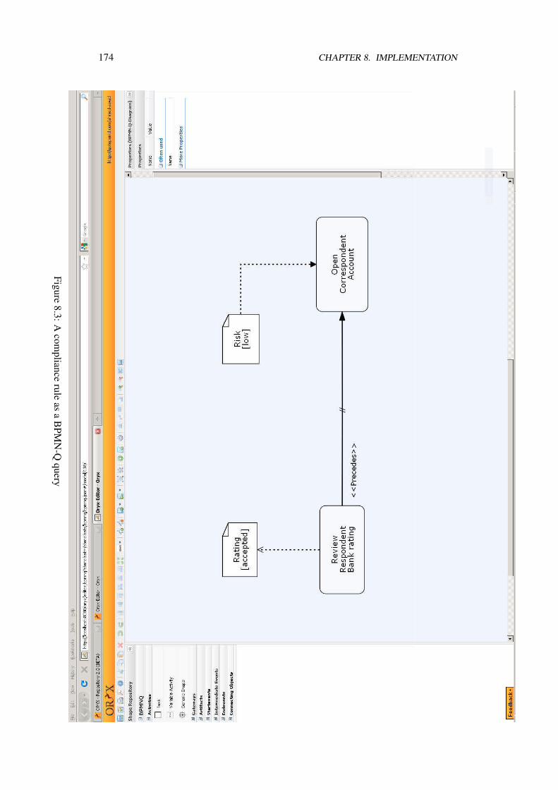
174 CHAPTER 8. IMPLEMENTATION
Figure8.3:A
compliance
ruleas
aB
PMN
-Qquery
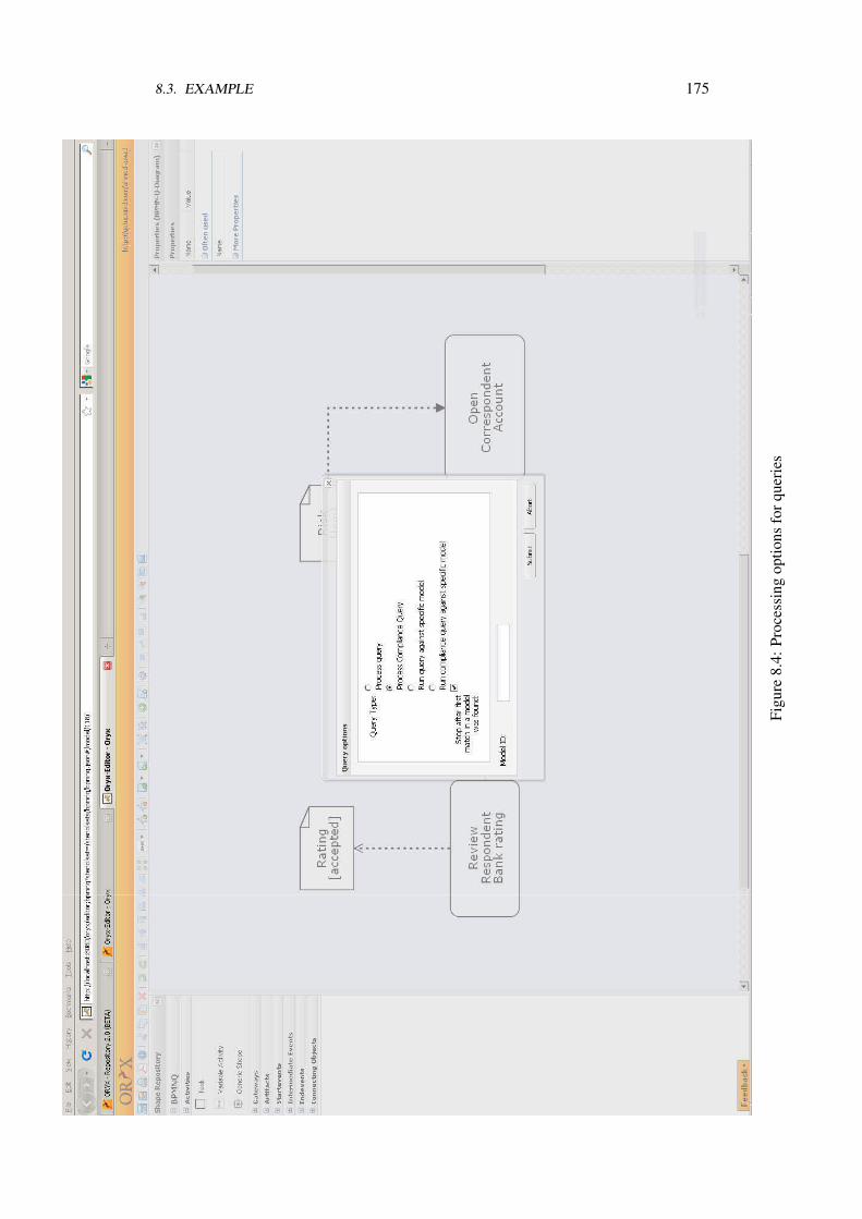
8.3. EXAMPLE 175
Figu
re8.
4:Pr
oces
sing
optio
nsfo
rque
ries
176 CHAPTER 8. IMPLEMENTATION
process model. In the latter case, the user is asked to enter the uri pointing to thatspecific process to be investigated.
With the pressing of the submit button, the query and the processing options areshipped to the back end. After doing the steps described in the previous section forcompliance checking, the user gets feedback in the form of process model previews asshown in Figure 8.5. By double clicking on a certain preview, the user gets the feedbackabout that specific process, whether compliant or not. In case of violations, the violatingpart is highlighted as shown in Figure 8.6
As can be noticed, the generation of anti patterns is totally transparent to the user.Only the matches to the anti patterns are returned as highlighting of violating parts of theprocess to the user.
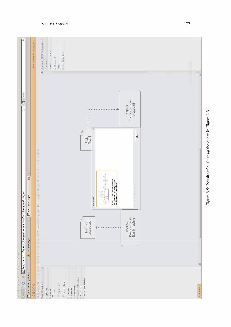
8.3. EXAMPLE 177
Figu
re8.
5:R
esul
tsof
eval
uatin
gth
equ
ery
inFi
gure
8.3
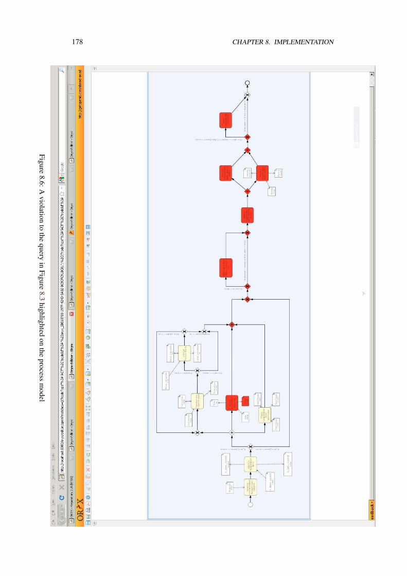
178 CHAPTER 8. IMPLEMENTATION
Figure8.6:A
violationto
thequery
inFigure
8.3highlighted
onthe
processm
odel
Chapter 9
Discussion
In this chapter we provide a critical discussion about the contributions in this thesis.Our discussion will illustrate strengths and limitations of our approach and revisit theassumptions introduced in Section 2.3. Also, we discuss how far we were aligned withthe requirements discussed in Section 2.2.
Summary
We introduced a pattern-based approach for compliance checking. Using BPMN-Q visualqueries to express compliance requirements, we have provided a graphical notation toexpress compliance rules, Req. 9. The visual nature of the language, that is very close tothe way process models are expressed, makes it easy for business people to understandand discuss about it. Also, each query is stored on its own as an artifact that can beassociated with arbitrary metadata that allows tracking of a compliance requirement, Req.
2. This helps the organization assess the number of control objectives it has establishedto meet compliance requirements. Finally, formal checking is possible since each patternis mapped to a temporal logic formula, Req. 1.
When a set of compliance rules are related to a process model, the conjunction of theserules are checked against the process. However, in some cases, a rule might be requiredto hold when another rule does not hold. That is, the compliance to one rule is requiredonly when the process is violating another rule [103]. Currently this is not addressed.Modeling this reparation relationship requires the definition of a new modeling construct.On the technical level, we can check the disjunction of rules rather their conjunction.
Checking consistency among compliance rules, Req. 3, was divided into redundancyand conflict checks. While conflict checking is complete, assuming that sufficient domainknowledge is present. Redundancy checking is based on establishing a sort of logicalequivalence between the different compliance patterns. Thus, we cannot claim thatredundancy checking is complete.
179
180 CHAPTER 9. DISCUSSION
To explain violations to compliance rules, in general, we used a two step approachwhere the first step is to query the process behavior about the causes of the violationand in the second step BPMN-Q anti pattern queries are generated to highlight partsof the process causing violation. Although there is a processing overhead due to theneed to issue several temporal logic queries, this could be justified by the need to becomplete. That is, we need to provide the user with every possible cause of violation,Req. 6. This, in turn, will save and focus the effort of the user compared to the alternativeof the counterexample-driven violation explanation. In the latter case, the user has torepeat a check-explain-resolve each time model checking identifies a violation, whichalso contains a repeated cost of model checking.
To resolve violations, Req. 7, we discussed several algorithms that were dedicatedto special kinds of compliance violations. These approaches depend heavily on thedomain knowledge. This is no surprise as the very first requirement to have an effectivecompliance management approach is to have a deep knowledge about the businessdomain [65]. While our approach to resolve violations is not complete, it helps the useridentify areas of conflict and missing or incomplete knowledge about the domain.
Applicability
In Section 2.3, we have established a set of assumptions that make our approach applicablein real life. Here, we discuss the relaxation of some of these assumptions and howthat relaxation affects the applicability of the approach. The success of establishingan effective compliance management is directly related to the level of maturity of theorganization [66]. Thus, the applicability of our approach in real life depends on the levelof maturity of the organization. The entry maturity level is that organizations have explicitviews on their business operations in terms of process models [5, 65]. This has scopedthe thesis from the beginning. However, in many cases, organizations might not havethat level of maturity. In such cases, organizations might benefit from process miningtechniques [136] to help automate the discovery of business processes. Yet, this dependson whether the organization has an automated support for its daily business operations.If that is not the case, there is no way but starting a manual business process discoveryusing traditional requirements elicitation techniques, as in [65].
To correlate compliance rules with business processes, we assumed the availability ofa common set of tags that can be used to annotate both compliance rules and businessprocesses. This is also is related to the level of maturity of the organization. That is,the agreement on a set of terms that have a common meaning. If this is not the case,users can benefit from the querying nature of BPMN-Q to identify process models thatare subject to compliance checking. However, the success of this approach assumes acommon glossary to label activities in both queries and processes.
We assume that the organization has a glossary of vocabularies, activity labels, that isagreed upon. For instance, an activity with the label “Open account” is understood by allpeople in the domain and is agreed upon its business value. If this is not the case, there
181
is a range of semi automated approaches that can fill this gap. For instance, in [10], weshow how information retrieval (IR) techniques can be used to overcome this problem.Other approaches that use semantic annotations [69, 54] can be applied to annotate bothactivities in process models and in compliance queries. There are recent publications thatlook up labels of activities in a repository of business process models in order to findsemantic similarity [129]. We believe that the result of such research will be beneficial toorganizations and helps accelerate building their own glossary of activity labels.
Depending on the compliance rule and the domain knowledge, we might be able tosuggest a remedy to the process model that restores compliance. With our semi automatedapproach we can find, in some cases, a resolution to the violation automatically. If this isnot possible, we give the compliance officer directions about what is missing to resolveviolations. We believe that this helps the compliance officer assess the amount of changeneeded within the organization’s view on the business in order to achieve compliance.We admit that having the domain knowledge available in the form we suggest could onlybe available in very highly mature organizations. However, we believe that providing aguide about what knowledge to collect allows organizations to incrementally build theirdomain knowledge. We also see that this is a necessary step that helps organization gainmore insight about its business operations and in the same time provides better capabilityto respond to future compliance requirements.
Compliance for Declarative Business Processes
Declarative business process modeling is a way to allow flexibility in processes. Processesare modeled by specifying a set of execution ordering constraints on a set of activities [107,105]. Compliance rules discussed in this thesis can be integrated to provide a compliantexecution of process instances. In that case, having an execution engine that is faithful tothe execution constraints, including compliance rules, there is no chance for violation.Thus, there is no need to check for violation and will be no need also to resolve them.However, there is still the need to identify inconsistencies between rule sets.
The compliance patterns we identified overlap with those identified by Pesic in [105].Yet, data flow and conditional rules are unique to our approach. When integrated withdeclarative approaches, more expressiveness is gained to provide finer grain restrictionson process execution.
Future Work
There are open issues that are subject to future work.
Business Process Synthesis
As compliance requirements and business objectives are developed separately, there isa chance of conflicts. Our approach to check conflict freedom of a set of compliancerules relied on finding computations, Büchi automaton, that satisfies the conjunction of
182 CHAPTER 9. DISCUSSION
the rules. The idea was to decide conflict freedom if the resulting automaton has anaccepting run. However, the decision was bound by the availability of sufficient domainknowledge. We see an opportunity to help gain better understanding of the domain andbetter communication between compliance experts on the one hand and business expertson the other hand by means of process synthesis. From a Büchi automaton, we canderive a process template that can serve as an artifact for the communication. Both thecompliance expert and the process expert can decide whether the resulting template is ofvalue. The more precise the resulting template the better communication can be reachedamong experts. The technical approach to generate process template out of compliancespecification is seen as a future work.
Supporting Compliance at Other Process Life Cycle Phases
Under the assumption that organizations strictly follow their documented process modelseither in the form of automated processes or by work procedures followed by employees,we can assume a compliant execution of processes, when violations are discoveredand corrected at process definition. However, due to the dynamic nature of executionenvironments, it is likely to have exceptions where violation can occur.
To guarantee compliance at automated process execution, we can foresee two direc-tions to monitor the status of compliance. The first approach is via instant monitoring ofrunning processes. We believe that work in [115] constitutes the first step to realize aninstant monitoring scheme. Another approach benefits from the well developed processmining [140, 138] techniques to assess the compliance of completed instances. Theintegration with process mining can widen the scope of applicability to organizations thatdo not have explicit process execution engines. The major difference between the twoapproaches above is that with instant monitoring we are still able to prevent violationsor at least have an informed violation in extreme cases. On the other hand, with processmining, we can only report about violations after they have occurred.
Using execution logs, it is also possible not only to identify violations on processdefinition level, the case of process mining, but also to quantify the number of violations,in terms of specific instances that have violations. In that case, querying rather than miningthe logs is needed. This can be approached by the notion of anti patterns introduced inthis thesis. An anti pattern can be mapped to some sort of a query that is checked againstthe execution log. The number of matches identify the amount of violating instances. Webelieve that this can be then integrated into business process intelligence tools to providetop management with a realistic view of their compliance status.
Compliance Verification Enhancement
On a technical level, regarding the thesis in hand, there is a need to enhance the verificationapproach discussed in this thesis. Model checking was the main technique to decideabout compliance, although we discussed simple structural checks about non compliance.
183
However, model checking is known to suffer from state space explosions. Within processmodels, the cause of state space explosion is having parallel threads. In literature, partialorder reduction techniques were developed to overcome this problem when verifyingproperties concerned with deadlock-freedom of processes. The techniques were simplyconcerned with picking only one sequence of states from the start of the parallel thread toits end rather than needlessly investigating all possible sequences. While this is acceptablefor deadlock-freedom checking, it is not suitable for properties related to compliancerules. For instance, if we check a rule on the form A Leads to B and it happens that Aand B are on different branches in a parallel thread, using partial order reduction cansometimes mistakenly report compliance if the sequence in which B executes after A ispicked.
To overcome this problem, we believe that a hybrid approach for checking is needed.That is, structural checking should be investigated first. The approach of using structuraldecomposition techniques is a promising starting point. Actually, the violation catalogdiscussed in Chapter 7 constitutes the starting point. Depending on the compliance rule,e.g., control flow rules, and the degree of structuredness of business process models,compliance can efficiently be decided. In case it is not possible to structurally decide,only the unstructured part of the process models needs to be investigated via state spaceexploration. However, there are still open points regarding conditional rules and howto correctly map unstructured parts of the process to behavioral models. This is left forfuture work.


Bibliography
[1] Business Process Modeling Notation 1.2 (BPMN 1.2) Specification, Final Adopted Specifi-cation. Technical report, OMG, 2009. [cited at p. 19, 34, 41, 42, 44, 57]
[2] COMPAS: Compliance-driven Models, Languages, and Architectures for Service, 2008.7th Framework Programme Information and Communication Technologies. [cited at p. 26]
[3] W.M.P. van der Aalst. Verification of Workflow Nets. In Application and Theory of PetriNets 1997, volume 1248 of Lecture Notes in Computer Science, pages 407–426, Berlin,1997. Springer Verlag. [cited at p. 5, 18, 44]
[4] Ashish Agrawal, Mike Amend, Manoj Das, Mark Ford, Chris Keller, Matthias Klopp-mann, Dieter König, Frank Leymann, Ralf Müller, Gerhard Pfau, Karsten Plösser, RaviRangaswamy, Alan Rickayzen, Michael Rowley, Patrick Schmidt, Ivana Trickovic, AlexYiu, and Matthias Zeller. WS-BPEL Extension for People (BPEL4People), Version 1.0.2007. [cited at p. 34]
[5] Rakesh Agrawal, Christopher M. Johnson, Jerry Kiernan, and Frank Leymann. TamingCompliance with Sarbanes-Oxley Internal Controls Using Database Technology. In LingLiu, Andreas Reuter, Kyu-Young Whang, and Jianjun Zhang, editors, ICDE, page 92. IEEEComputer Society, 2006. [cited at p. 38, 180]
[6] Marco Alberti, Federico Chesani, Marco Gavanelli, Evelina Lamma, Paola Mello, MarcoMontali, and Paolo Torroni. Expressing and Verifying Business Contracts with AbductiveLogic Programming. Int. J. Electron. Commerce, 12(4):9–38, 2008. [cited at p. 36]
[7] Ahmed Awad. BPMN-Q: A Language to Query Business Processes. In Manfred Reichert,Stefan Strecker, and Klaus Turowski, editors, EMISA, volume P-119 of LNI, pages 115–128.GI, 2007. [cited at p. 18, 52, 55]
[8] Ahmed Awad, Gero Decker, and Niels Lohmann. Diagnosing and repairing data anomaliesin process models. In Stefanie Rinderle-Ma, Shazia Sadiq, and Frank Leymann, editors,BPM 2009 Workshops, volume 43 of Lecture Notes in Business Information Processing,pages 5–16. Springer-Verlag, September 2009. [cited at p. 44, 45, 48, 154]
[9] Ahmed Awad, Gero Decker, and Mathias Weske. Efficient Compliance Checking UsingBPMN-Q and Temporal Logic. In Marlon Dumas, Manfred Reichert, and Ming-ChienShan, editors, BPM, volume 5240 of Lecture Notes in Computer Science, pages 326–341.Springer, 2008. [cited at p. 67]
185
186 BIBLIOGRAPHY
[10] Ahmed Awad, Artem Polyvyanyy, and Mathias Weske. Semantic Querying of BusinessProcess Models. In EDOC, pages 85–94. IEEE Computer Society, 2008. [cited at p. 52, 181]
[11] Ahmed Awad and Frank Puhlmann. Structural Detection of Deadlocks in Business ProcessModels. In Witold Abramowicz and Dieter Fensel, editors, BIS, volume 7 of Lecture Notesin Business Information Processing, pages 239–250. Springer, 2008. [cited at p. 52]
[12] Ahmed Awad, Sergey Smirnov, and Mathias Weske. Resolution of compliance violation inbusiness process models: A planning-based approach. In Robert Meersman, Tharam S.Dillon, and Pilar Herrero, editors, OTM Conferences (1), volume 5870 of Lecture Notes inComputer Science, pages 6–23. Springer, 2009. [cited at p. 152]
[13] Ahmed Awad, Sergey Smirnov, and Mathias Weske. Towards Resolving ComplianceViolations in Business Process Models. In Shazia Sadiq, Marta Indulska, and Michael zurMuehlen, editors, GRCIS, volume 459, pages 18–32. CEUR-WS.org, 2009. [cited at p. 147]
[14] Ahmed Awad, Matthias Weidlich, and Mathias Weske. Specification, verification andexplanation of violation for data aware compliance rules. In Luciano Baresi, Chi-Hung Chi,and Jun Suzuki, editors, ICSOC/ServiceWave, volume 5900 of Lecture Notes in ComputerScience, pages 500–515. Springer, 2009. [cited at p. 67]
[15] Ahmed Awad, Matthias Weidlich, and Mathias Weske. Consistency Checking of Compli-ance Rules. In BIS, volume 47 of Lecture Notes in Business Information Processing, pages106–118. Springer, 2010. [cited at p. 93]
[16] Ahmed Awad and Mathias Weske. Visualization of compliance violation in businessprocess models. In Stefanie Rinderle-Ma, Shazia Sadiq, and Frank Leymann, editors, BPM2009 Workshops, volume 43 of Lecture Notes in Business Information Processing, pages182–193. Springer, 2009. [cited at p. 67]
[17] Jos C. M. Baeten and W. P. Weijland and. Process Algebra. Cambridge Tracts in TheoreticalComputer Science Series. Cambridge University Press, 1990. [cited at p. 41]
[18] Roderick Bloem, Kavita Ravi, and Fabio Somenzi. Efficient decision procedures for modelchecking of linear time logic properties. In Nicolas Halbwachs and Doron Peled, editors,CAV, volume 1633 of Lecture Notes in Computer Science, pages 222–235. Springer, 1999.[cited at p. 64]
[19] Riccardo Bonazzi and Yves Pigneur. Compliance Management in Multi-actor Contexts. InShazia Sadiq, Marta Indulska, Michael zur Muehlen, Eric Dubois, and Paul Johannesson,editors, Governance, Risk and Compliance in Information Systems, volume 459, pages91–105. CEUR-WS, 2009. [cited at p. 25, 89]
[20] Glenn Bruns and Patrice Godefroid. Temporal logic query checking. In LICS ’01: Pro-ceedings of the 16th Annual IEEE Symposium on Logic in Computer Science, page 409,Washington, DC, USA, 2001. IEEE Computer Society. [cited at p. 64, 65, 130]
[21] William Chan. Temporal-Locig Queries. In CAV, volume 1855 of Lecture Notes inComputer Science, pages 450–463. Springer, 2000. [cited at p. 64, 65, 130]
[22] Marsha Chechik and Arie Gurfinkel. TLQSolver: A Temporal Logic Query Checker. InCAV, volume 2725 of Lecture Notes in Computer Science, pages 210–214. Springer, 2003.[cited at p. 65, 130]
BIBLIOGRAPHY 187
[23] Alessandro Cimatti, Edmund M. Clarke, Fausto Giunchiglia, and Marco Roveri. NUSMV:A new symbolic model checker. International Journal on Software Tools for TechnologyTransfer, 2(4):410–425, 2000. [cited at p. 68]
[24] Edmund M. Clarke, Orna Grumberg, and Doron A. Peled. Model Checking. MIT Press,1999. [cited at p. 17, 60, 67, 93, 98]
[25] Financial Services Commission. Guidelines on anti-money laundering & counter-financingof terrorism, 2007. [cited at p. 4, 12, 13, 68, 103]
[26] Michael T. Cox, Héctor Muñoz-Avila, and Ralph Bergmann. Case-based planning. Knowl-edge Eng. Review, 20(3):283–287, 2005. [cited at p. 147]
[27] Florian Daniel, Fabio Casati, Vincenzo D’Andrea, Emmanuel Mulo, Uwe Zdun, SchahramDustdar, Steve Strauch, David Schumm, Frank Leymann, Samir Sebahi, Fabien De Marchi,and Mohand-Said Hacid. Business Compliance Governance in Service-Oriented Archi-tectures. In Irfan Awan, Muhammad Younas, Takahiro Hara, and Arjan Durresi, editors,AINA, pages 113–120. IEEE Computer Society, 2009. [cited at p. 26, 27]
[28] Pallab Dasgupta. A Roadmap for Formal Property Verification. Springer, 2006. [cited at p. 94,
95, 100]
[29] Gero Decker, Hagen Overdick, and Mathias Weske. Oryx - An Open Modeling Platform forthe BPM Community. In Marlon Dumas, Manfred Reichert, and Ming-Chien Shan, editors,BPM, volume 5240 of Lecture Notes in Computer Science, pages 382–385. Springer, 2008.[cited at p. 170]
[30] Juliane Dehnert and Peter Rittgen. Relaxed soundness of business processes. In Klaus R.Dittrich, Andreas Geppert, and Moira C. Norrie, editors, CAiSE, volume 2068 of LectureNotes in Computer Science, pages 157–170. Springer, 2001. [cited at p. 5, 18]
[31] Remco M. Dijkman, Marlon Dumas, and Chun Ouyang. Semantics and analysis of businessprocess models in BPMN. Inf. Softw. Technol., 50(12):1281–1294, 2008. [cited at p. 18, 45,
46]
[32] Yurdaer Doganata and Francisco Curbera. Effect of Using Automated Auditing Toolson Detecting Compliance Failures in Unmanaged Processes. In BPM ’09: Proceedingsof the 7th International Conference on Business Process Management, Lecture Notes inComputer Science, pages 310–326, Berlin, Heidelberg, 2009. Springer-Verlag. [cited at p. 38]
[33] Matthew B. Dwyer, George S. Avrunin, and James C. Corbett. Patterns in propertyspecifications for finite-state verification. In ICSE, pages 411–420, 1999. [cited at p. 67, 68,
71]
[34] Cindy Eisner and Doron Peled. Comparing Symbolic and Explicit Model Checking ofa Software System. In Proceedings of the 9th International SPIN Workshop on ModelChecking of Software, pages 230–239, London, UK, 2002. Springer-Verlag. [cited at p. 67]
[35] E. Allen Emerson and Joseph Y. Halpern. Decision procedures and expressiveness in thetemporal logic of branching time. J. Comput. Syst. Sci., 30(1):1–24, 1985. [cited at p. 61, 67]
188 BIBLIOGRAPHY
[36] Gregor Engels, Christian Soltenborn, and Heike Wehrheim. Analysis of uml activities usingdynamic meta modeling. In Marcello M. Bonsangue and Einar Broch Johnsen, editors,FMOODS, volume 4468 of Lecture Notes in Computer Science, pages 76–90. Springer,2007. [cited at p. 31]
[37] Amy P. Felty and Kedar S. Namjoshi. Feature specification and automated conflict detection.ACM Trans. Softw. Eng. Methodol., 12(1):3–27, 2003. [cited at p. 94]
[38] Christian Flender and Thomas Freytag. Visualizing the Soundness of Workflow Nets.In 13th Workshop Algorithms and Tools for Petri Nets, AWPN 2006, pages 47–52, 2006.[cited at p. 113]
[39] Alexander Förster, Gregor Engels, and Tim Schattkowsky. Activity Diagram Patternsfor Modeling Quality Constraints in Business Processes. In Lionel C. Briand and ClayWilliams, editors, MoDELS, volume 3713 of Lecture Notes in Computer Science, pages2–16. Springer, 2005. [cited at p. 18, 31, 35, 67]
[40] Alexander Förster, Gregor Engels, Tim Schattkowsky, and Ragnhild Van Der Straeten. Apattern-driven development process for quality standard-conform business process models.In IEEE Symposium on Visual Languages and Human-Centric Computing VL, 2006.[cited at p. 31, 35]
[41] Alexander Förster, Gregor Engels, Tim Schattkowsky, and Ragnhild Van Der Straeten.Verification of Business Process Quality Constraints Based on Visual Process Patterns. InTASE, pages 197–208. IEEE Computer Society, 2007. [cited at p. 31, 35]
[42] Erich Gamma, Richard Helm, Ralph Johnson, and John Vlissides. Design patterns:elements of reusable object-oriented software. Addison-Wesley Professional, 1995.[cited at p. 67]
[43] Paul Gastin and Denis Oddoux. Fast LTL to Büchi Automata Translation. In CAV, volume2102 of Lecture Notes in Computer Science, pages 53–65. Springer, 2001. [cited at p. 93]
[44] Rob Gerth, Doron Peled, Moshe Y. Vardi, and Pierre Wolper. Simple on-the-fly automaticverification of linear temporal logic. In In Protocol Specification Testing and Verification,pages 3–18. Chapman & Hall, 1995. [cited at p. 93]
[45] Sepideh Ghanavati, Daniel Amyot, and Liam Peyton. Towards a Framework for TrackingLegal Compliance in Healthcare. In John Krogstie, Andreas L. Opdahl, and GuttormSindre, editors, CAiSE, volume 4495 of Lecture Notes in Computer Science, pages 218–232. Springer, 2007. [cited at p. 38]
[46] Aditya Ghose and George Koliadis. Auditing business process compliance. In Bernd J.Krämer, Kwei-Jay Lin, and Priya Narasimhan, editors, ICSOC, volume 4749 of LectureNotes in Computer Science, pages 169–180. Springer, 2007. [cited at p. 33, 35]
[47] Christopher Giblin, Alice Y. Liu, Samuel Müller, Birgit Pfitzmann, and Xin Zhou. Regula-tions Expressed As Logical Models (REALM). In Proceeding of the 2005 conference onLegal Knowledge and Information Systems, pages 37–48, Amsterdam, The Netherlands,The Netherlands, 2005. IOS Press. [cited at p. 36]
BIBLIOGRAPHY 189
[48] Christopher Giblin, Samuel Müller, and Birgit Pfitzmann. From Regulatory Policies toEvent Monitoring Rules: Towards Model-Driven Compliance Automation. ResearchReport RZ 3662, IBM Zurich Research Laboratory, 2006. [cited at p. 36]
[49] Adrian Giurca, Dragan Gasevic, and Kuldar Taveter. Handbook of Research on EmergingRule-Based Languages and Technologies: Open Solutions and Approaches, volume I.INFORMATION SCIENCE REFERENCE, May 2009. [cited at p. 28, 89]
[50] Stijn Goedertier and Jan Vanthienen. Designing Compliant Business Processes withObligations and Permissions, 2nd Workshop on Business Processes Design (BPD’06),Proceedings. In Johann Eder and Schahram Dustdar, editors, Business Process ManagementWorkshops, volume 4103 of Lecture Notes in Computer Science, pages 5–14. SpringerVerlag, 2006. [cited at p. 29]
[51] Guido Governatori, Jörg Hoffmann, Shazia Wasim Sadiq, and Ingo Weber. Detectingregulatory compliance for business process models through semantic annotations. InDanilo Ardagna, Massimo Mecella, and Jian Yang, editors, Business Process ManagementWorkshops, volume 17 of Lecture Notes in Business Information Processing, pages 5–17.Springer, 2008. [cited at p. 31]
[52] Guido Governatori and Zoran Milosevic. Dealing with contract violations: formalismand domain specific language. In EDOC, pages 46–57. IEEE Computer Society, 2005.[cited at p. 29, 36]
[53] Guido Governatori, Zoran Milosevic, and Shazia Sadiq. Compliance checking betweenbusiness processes and business contracts. In EDOC, pages 221–232, Washington, DC,USA, 2006. IEEE Computer Society. [cited at p. 31, 35]
[54] Guido Governatori and Shazia Sadiq. Handbook of Research on BPM, chapter The Journeyto Business Process Compliance, pages 426–454. IGI Global, 2009. [cited at p. 31, 35, 181]
[55] Jun Han, Yan Jin, Zheng Li, Tan Phan, and Jian Yu. Guiding the Service CompositionProcess with Temporal Business Rules. In ICWS, pages 735–742. IEEE Computer Society,2007. [cited at p. 29]
[56] Hans-Jörg Happel and Ljiljana Stojanovic. Ontoprocess - a prototype for semantic busi-ness process verification using swrl rules. In 3rd European Semantic Web Conference(ESWC2006), June 2006. [cited at p. 32]
[57] Thomas E. Hartman. The Cost of Being Public in the Era of Sarbanes-Oxley. [Chicago,Ill.] : Foley & Lardner, June 2006. [cited at p. 4]
[58] Jörg Hoffmann, Ingo Weber, and Guido Governatori. On compliance checking for clausalconstraints in annotated process models. Information Systems Frontiers, Special Issue onGovernance, Risk, and Compliance, available online, 2009. [cited at p. 32]
[59] Gerard J. Holzmann. The Model Checker SPIN. Software Engineering, 23(5):279–295,1997. [cited at p. 68]
[60] Chung-Wah Norris Ip. State Reduction Methods for Automatic Formal Verification. PhDthesis, Department of Computer Science, Stanford University, 1996. [cited at p. 98]
190 BIBLIOGRAPHY
[61] R. Johnson, D. Pearson, and K. Pingali. The program structure tree: computing controlregions in linear time. SIGPLAN Not., 29(6):171–185, 1994. [cited at p. 144]
[62] Vandana Kabilan, Paul Johannesson, and Dickson M. Rugaimukamu. Business ContractObligation Monitoring through Use of Multi Tier Contract Ontology. In Robert Meersmanand Zahir Tari, editors, OTM Workshops, volume 2889 of Lecture Notes in ComputerScience, pages 690–702. Springer, 2003. [cited at p. 36]
[63] Martin Kähmer, Maike Gilliot, and G. Muller. Automating privacy compliance with expdt.In CEC/EEE, pages 87–94. IEEE, 2008. [cited at p. 37]
[64] Dimitris Karagiannis. A business process-based modelling extension for regulatory compli-ance. In Martin Bichler, Thomas Hess, Helmut Krcmar, Ulrike Lechner, Florian Matthes,Arnold Picot, Benjamin Speitkamp, and Petra Wolf, editors, Multikonferenz Wirtschaftsin-formatik. GITO-Verlag, Berlin, 2008. [cited at p. 19]
[65] Dimitris Karagiannis, John Mylopoulos, and Margit Schwab. Business process-basedregulation compliance: The case of the sarbanes-oxley act. In RE, pages 315–321. IEEE,2007. [cited at p. 5, 180]
[66] Matthias Kehlenbeck, Thorben Sandner, and Michael H. Breitner. Application and eco-nomic implications of an automated requirement-oriented and standard-based compliancemonitoring and reporting prototype. In ARES, pages 468–474. IEEE Computer Society,2010. [cited at p. 180]
[67] G. Keller, M. Nüttgens, and A.W. Scheer. Semantische Prozessmodellierung auf derGrundlage “Ereignisgesteuerter Prozessketten (EPK)”. Technical Report 89, Institut fürWirtschaftsinformatik, Saarbrücken, 1992. [cited at p. 41, 42]
[68] Marwane El Kharbili, Ana Karla Alves de Medeiros, Sebastian Stein, and W.M.P. van derAalst. Business Process Compliance Checking: Current State and Future Challenges. InPeter Loos, Markus Nüttgens, Klaus Turowski, and Dirk Werth (Hrsg.), editors, Model-lierung betrieblicher Informationssysteme (MobIS 2008). Modellierung zwischen SOA undCompliance Management, volume P-141 of LNI, pages 107–113. GI, November 2008.[cited at p. 13]
[69] Marwane El Kharbili and Sebastian Stein. Policy-Based Semantic Compliance Checkingfor Business Process Management. In Peter Loos, Markus Nüttgens, Klaus Turowski, andDirk Werth, editors, Proceedings of Workshops colocated with the MobIS-2008 conference:EPK-2008, KobAS-2008 and ModKollGP-2008, pages 178–192. CEUR-WS.org, November2008. [cited at p. 24, 25, 27, 181]
[70] Marwane El Kharbili, Sebastian Stein, Ivan Markovic, and Elke Pulvermüller. Towardsa Framework for Semantic Business Process Compliance Management. In Shazia Sadiq,Marta Indulska, Michael zur Muehlen, Xavier Franch, Ela Hunt, and Remi Coletta, editors,Proceedings of the 1st International Workshop on Governance, Risk and Compliance:Applications in Information Systems (GRCIS’08), pages 1–15. CEUR-WS.org, June 2008.[cited at p. 25, 27]
[71] Nadzeya Kiyavitskaya, Nicola Zeni, Travis D. Breaux, Annie I. Antón, James R. Cordy,Luisa Mich, and John Mylopoulos. Automating the Extraction of Rights and Obligationsfor Regulatory Compliance. In ER ’08: Proceedings of the 27th International Conference
BIBLIOGRAPHY 191
on Conceptual Modeling, pages 154–168, Berlin, Heidelberg, 2008. Springer-Verlag.[cited at p. 20, 38]
[72] Natallia Kokash and Farhad Arbab. Formal behavioral modeling and compliance analysisfor service-oriented systems. In Frank S. de Boer, Marcello M. Bonsangue, and EricMadelain, editors, FMCO, volume 5751 of Lecture Notes in Computer Science, pages21–41. Springer, 2008. [cited at p. 33, 35]
[73] Akhil Kumar and Rong Liu. A Rule-Based Framework Using Role Patterns for BusinessProcess Compliance. In RuleML, volume 5321 of Lecture Notes in Computer Science,pages 58–72. Springer, 2008. [cited at p. 33, 35]
[74] Jochen Malte Küster, Ksenia Ryndina, and Harald Gall. Generation of Business ProcessModels for Object Life Cycle Compliance. In Gustavo Alonso, Peter Dadam, and MichaelRosemann, editors, BPM, volume 4714 of Lecture Notes in Computer Science, pages165–181. Springer, 2007. [cited at p. 30, 70]
[75] Ralf Laue and Ahmed Awad. Visualization of Business Process Modeling Anti Patterns.In P. Bottoni, E. Guerra, J. de Lara, T. Margaria, J. Padberg, and G. Taentzer, editors,Proceedings of the 1st International Workshop on Visual Formalisms for Patterns (VFfP2009), Corvallis, OR (USA) (to be published). European Association of Software Scienceand Technology, 2009. [cited at p. 52]
[76] Ying Liu, Samuel Müller, and Ke Xu. A static compliance-checking framework for businessprocess models. IBM SYSTEMS JOURNAL, 46(2):335–362, 2007. [cited at p. 18, 32, 35]
[77] Alessio Lomuscio, Hongyang Qu, and Monika Solanki. Towards Verifying ContractRegulated Service Composition. In ICWS ’08: Proceedings of the 2008 IEEE InternationalConference on Web Services, pages 254–261, Washington, DC, USA, 2008. IEEE ComputerSociety. [cited at p. 31]
[78] Volkmar Lotz, Emmanuel Pigout, Peter M. Fischer, Donald Kossmann, Fabio Massacci,and Alexander Pretschner. Towards systematic achievement of compliance in service-oriented architectures: The master approach. Wirtschaftsinformatik, 50(5):383–391, 2008.[cited at p. 37]
[79] R. Lu, Sh. Sadiq, and G. Governatori. Measurement of Compliance Distance in BusinessProcesses. Inf. Sys. Manag., 25(4):344–355, 2008. [cited at p. 31, 35]
[80] Ruopeng Lu, Shazia Wasim Sadiq, and Guido Governatori. Compliance Aware BusinessProcess Design. In Business Process Management Workshops, volume 4928 of LectureNotes in Computer Science, pages 120–131. Springer, 2007. [cited at p. 31, 35]
[81] Linh Thao Ly, Kevin Göser, Stefanie Rinderle-Ma, and Peter Dadam. Compliance ofSemantic Constraints- A Requirements Analysis for Process Management Systems. InShazia Sadiq, Marta Indulska, Michael zur Muehlen, Xavier Franch, Ela Hunt, and RemiColetta, editors, Proceedings of the 1st International Workshop on Governance, Riskand Compliance: Applications in Information Systems (GRCIS’08), pages 16–30. CEUR-WS.org, June 2008. [cited at p. 13, 25, 27]
[82] Linh Thao Ly, Stefanie Rinderle, and Peter Dadam. Semantic Correctness in AdaptiveProcess Management Systems. In Schahram Dustdar, José Luiz Fiadeiro, and Amit P.
192 BIBLIOGRAPHY
Sheth, editors, Business Process Management, volume 4102 of Lecture Notes in ComputerScience, pages 193–208. Springer, 2006. [cited at p. 32, 35, 60]
[83] Linh Thao Ly, Stefanie Rinderle, and Peter Dadam. Integration and verification of semanticconstraints in adaptive process management systems. Data Knowl. Eng., 64(1):3–23, 2008.[cited at p. 32, 35]
[84] Linh Thao Ly, Stefanie Rinderle-Ma, Kevin Göser, and Peter Dadam. On EnablingIntegrated Process Compliance with Semantic Constraints in Process Management SystemsRequirements, Challenges, Solutions. Information System Frontiers, 2009. [cited at p. 25, 27,
28]
[85] Monika Maidl. The common fragment of ctl and ltl. In FOCS, pages 643–652, 2000.[cited at p. 64]
[86] Annapaola Marconi, Marco Pistore, and Paolo Traverso. Automated Composition of WebServices: the ASTRO Approach. IEEE Data Eng. Bull., 31(3):23–26, 2008. [cited at p. 146]
[87] Axel Martens. Analyzing web service based business processes. In Maura Cerioli, editor,FASE, volume 3442 of Lecture Notes in Computer Science, pages 19–33. Springer, 2005.[cited at p. 5]
[88] Kenneth L. McMillan. Symbolic Model Checking An approach to the state explosionproblem. PhD thesis, Carnegie Mellon University, May 1992. [cited at p. 98]
[89] Jan Mendling, Karsten Ploesser, and Mark Strembeck. Specifying Separation of DutyConstraints in BPEL4People Processes. In Witold Abramowicz and Dieter Fensel, editors,BIS, volume 7 of Lecture Notes in Business Information Processing, pages 273–284.Springer, 2008. [cited at p. 34]
[90] Robin Milner, Joachim Parrow, and David Walker. A calculus of mobile processes, part i/ii.Information and Computation, 100:1–77, 1992. [cited at p. 41]
[91] Zoran Milosevic, Audun Jøsang, Theodosis Dimitrakos, and Mary Anne Patton. Discre-tionary Enforcement of Electronic Contracts. In EDOC, pages 39–50. IEEE ComputerSociety, 2002. [cited at p. 36]
[92] Zoran Milosevic, Shazia Wasim Sadiq, and Maria E. Orlowska. Towards a Methodologyfor Deriving Contract-Compliant Business Processes. In Schahram Dustdar, José LuizFiadeiro, and Amit P. Sheth, editors, Business Process Management, volume 4102 ofLecture Notes in Computer Science, pages 395–400. Springer, 2006. [cited at p. 29]
[93] Zoran Milosevic, Shazia Wasim Sadiq, and Maria E. Orlowska. Translating businesscontract into compliant business processes. In EDOC, pages 211–220. IEEE ComputerSociety, 2006. [cited at p. 29]
[94] Kioumars Namiri and Nenad Stojanovic. Pattern-Based Design and Validation of BusinessProcess Compliance. In Robert Meersman and Zahir Tari, editors, OTM Conferences(1), volume 4803 of Lecture Notes in Computer Science, pages 59–76. Springer, 2007.[cited at p. 23, 27, 67]
BIBLIOGRAPHY 193
[95] Kioumars Namiri and Nenad Stojanovic. Using control patterns in business processescompliance. In Mathias Weske, Mohand-Said Hacid, and Claude Godart, editors, WISEWorkshops, volume 4832 of Lecture Notes in Computer Science, pages 178–190. Springer,2007. [cited at p. 23]
[96] Kioumars Namiri and Nenad Stojanovic. Towards a formal framework for business processcompliance. In Martin Bichler, Thomas Hess, Helmut Krcmar, Ulrike Lechner, FlorianMatthes, Arnold Picot, Benjamin Speitkamp, and Petra Wolf, editors, MultikonferenzWirtschaftsinformatik. GITO-Verlag, Berlin, 2008. [cited at p. 24, 27]
[97] Dana Nau, Malik Ghallab, and Paolo Traverso. Automated Planning: Theory & Practice.Morgan Kaufmann Publishers Inc., San Francisco, CA, USA, 2004. [cited at p. 19, 144, 146]
[98] OASIS. Universal Description Discovery and Integration UDDI, 2004. [cited at p. 59]
[99] Congress of the United States. Public Company Accounting Reform and Investor ProtectionAct (Sarbanes-Oxley Act). Public Law 107-204, 116 Stat. 745, 2002. [cited at p. 3, 4, 6, 38]
[100] OMG. Uml 2.0 superstructure specification. Technical report, 2004. [cited at p. 31, 41, 42]
[101] Basel Committee on Banking Supervision. Basel ii accord, 2004. [cited at p. 3]
[102] Martin Ouimet. Formal Software Verification: Model Checking and Theorem Prov-ing. Technical Report ESL-TIK-00214, Massachusetts Institute of Technology, 2008.[cited at p. 18]
[103] Vineet Padmanabhan, Guido Governatori, Shazia Wasim Sadiq, Robert Colomb, andAntonino Rotolo. Process Modelling: The Deontic Way. In Markus Stumptner, SvenHartmann, and Yasushi Kiyoki, editors, APCCM, volume 53 of CRPIT, pages 75–84.Australian Computer Society, 2006. [cited at p. 179]
[104] J. Scott Penberthy and Daniel S. Weld. UCPOP: A Sound, Complete, Partial Order Plannerfor ADL. In KR, pages 103–114, 1992. [cited at p. 153]
[105] Maja Pesic. Constraint-Based Workflow Management System: Shifting Control to Users.PhD thesis, Technische Universiteit Eindhoven, 2008. [cited at p. 181]
[106] Maja Pesic, Helen Schonenberg, and Wil M. P. van der Aalst. DECLARE: Full Support forLoosely-Structured Processes. In EDOC, pages 287–300. IEEE Computer Society, 2007.[cited at p. 41]
[107] Maja Pesic and Wil M. P. van der Aalst. A Declarative Approach for Flexible BusinessProcesses Management. In Johann Eder and Schahram Dustdar, editors, Business ProcessManagement Workshops, volume 4103 of Lecture Notes in Computer Science, pages169–180. Springer, 2006. [cited at p. 181]
[108] Aretem Plyvyanyy, ussi Vanhatalo, and Hagen Voelzer. Simplified Computation andGeneralization of the Refined Process Structure Tree . Technical Report RZ3745, IBM,2009. [cited at p. 166]
[109] Amir Pnueli. The temporal logic of programs. In SFCS ’77: Proceedings of the 18thAnnual Symposium on Foundations of Computer Science, pages 46–57, Washington, DC,USA, 1977. IEEE Computer Society. [cited at p. 61]
194 BIBLIOGRAPHY
[110] Artem Polyvyanyy, Sergey Smirnov, and Mathias Weske. The Triconnected Abstractionof Process Models. In Umeshwar Dayal, Johann Eder, Jana Koehler, and Hajo A. Reijers,editors, BPM, volume 5701 of Lecture Notes in Computer Science, pages 229–244. Springer,2009. [cited at p. 166]
[111] Frank Puhlmann and Mathias Weske. Investigations on soundness regarding lazy activities.In BPM 2006, Lecture Notes in Computer Science 4102, pages 145–160. Springer, 2006.[cited at p. 5]
[112] Manfred Reichert and Peter Dadam. ADEPTflex-Supporting Dynamic Changes of Work-flows Without Losing Control. J. Intell. Inf. Syst., 10(2):93–129, 1998. [cited at p. 32]
[113] Wolfgang Reisig. Petri Nets. Springer, EATCS Monographs on Theoretical ComputerScience edition, 1985. [cited at p. 45, 101]
[114] Stefanie Rinderle, Manfred Reichert, and Peter Dadam. Flexible Support of Team Processesby Adaptive Workflow Systems. Distributed and Parallel Databases, 16(1):91–116, 2004.[cited at p. 32]
[115] William N. Robinson. Implementing Rule-Based Monitors within a Framework for Contin-uous Requirements Monitoring. In HICSS. IEEE Computer Society, 2005. [cited at p. 182]
[116] Mohsen Rouached, Olivier Perrin, and Claude Godart. A Contract Layered Architecture forRegulating Cross-Organisational Business Processes. In Wil M. P. van der Aalst, BoualemBenatallah, Fabio Casati, and Francisco Curbera, editors, Business Process Management,volume 3649, pages 410–415, 2005. [cited at p. 36]
[117] Steffen Ryll. Querying the Data Perspective of Business Process Models. Master’s thesis,Business Process Technology Group, Hasso Plattner Institute, University of Potsdam,Germany, March 2009. [cited at p. 52, 55]
[118] Ksenia Ryndina, Jochen M. Küster, and Harald C. Gall. Consistency of Business ProcessModels and Object Life Cycles. In Models in Software Engineering, number 4364 inLecture Notes in Computer Science, pages 80–90. Springer, 2007. [cited at p. 75]
[119] Stefan Sackmann, Martin Kähmer, Maike Gilliot, and Lutz Lowis. A classification modelfor automating compliance. In CEC/EEE, pages 79–86. IEEE, 2008. [cited at p. 6, 7]
[120] Shazia Sadiq, Maria Orlowska, Wasim Sadiq, and Cameron Foulger. Data Flow andValidation in Workflow Modeling. In ADC ’04: Proceedings of the 15th Australasiandatabase conference, pages 207–214, Darlinghurst, Australia, Australia, 2004. AustralianComputer Society, Inc. [cited at p. 5, 44, 45]
[121] Shazia Wasim Sadiq, Guido Governatori, and Kioumars Namiri. Modeling Control Objec-tives for Business Process Compliance. In Gustavo Alonso, Peter Dadam, and MichaelRosemann, editors, BPM, volume 4714 of Lecture Notes in Computer Science, pages149–164. Springer, 2007. [cited at p. 11, 23, 27]
[122] Wasim Sadiq and Maria E. Orlowska. Analyzing process models using graph reductiontechniques. Inf. Syst., 25(2):117–134, 2000. [cited at p. 44]
BIBLIOGRAPHY 195
[123] Motoshi Saeki and Haruhiko Kaiya. Supporting the Elicitation of Requirements Compliantwith Regulations. In CAiSE ’08: Proceedings of the 20th international conference onAdvanced Information Systems Engineering, pages 228–242, Berlin, Heidelberg, 2008.Springer-Verlag. [cited at p. 38]
[124] Sherif Sakr and Ahmed Awad. A Framework for Querying Graph-Based Business ProcessModels. In Proceedings of the 19th International World Wide Web Conference (WWW),2010. (To Appear). [cited at p. 18, 170]
[125] Daniel Schleicher, Tobias Anstett, Frank Leymann, and Ralph Mietzner. MaintainingCompliance in Customizable Process Models. In Robert Meersman, Tharam S. Dillon, andPilar Herrero, editors, OTM Conferences (1), volume 5870 of Lecture Notes in ComputerScience, pages 60–75. Springer, 2009. [cited at p. 30]
[126] Karsten Schmidt. LoLA: A Low Level Analyser. In Application and Theory of PetriNets 2000: 21st International Conference, ICATPN 2000, Aarhus, Denmark, June 2000.Proceedings, volume 1825, page 465. Springer Berlin / Heidelberg, 2000. [cited at p. 170]
[127] Rainer Schmidt, Christian Bartsch, and Roy Oberhauser. Ontology-based representationof compliance requirements for service processes. In Martin Hepp, Knut Hinkelmann,Dimitris Karagiannis, Rüdiger Klein, and Nenad Stojanovic, editors, Proceedings of theWorkshop on Semantic Business Process and Product Lifecycle Management held inconjunction with the 3rd European Semantic Web Conference (ESWC 2007), Innsbruck,Austria, June 7, 2007, volume 251 of CEUR Workshop Proceedings. CEUR-WS.org, 2007.[cited at p. 24, 27]
[128] Dennis Shasha, Jason Tsong-Li Wang, and Rosalba Giugno. Algorithmics and Applicationsof Tree and Graph Searching. In Symposium on Principles of Database Systems, pages39–52, 2002. [cited at p. 54]
[129] Sergey Smirnov, Matthias Weidlich, Jan Mendling, and Mathias Weske. Action Patternsin Business Process Models. In Luciano Baresi, Chi-Hung Chi, and Jun Suzuki, editors,ICSOC/ServiceWave, volume 5900 of Lecture Notes in Computer Science, pages 115–129.Springer, 2009. [cited at p. 181]
[130] Pnina Soffer, Maya Kaner, and Yair Wand. Assigning Ontology-Based Semantics toProcess Models: The Case of Petri Nets. In Zohra Bellahsene and Michel Léonard, editors,CAiSE, volume 5074 of Lecture Notes in Computer Science, pages 16–31. Springer, 2008.[cited at p. 54]
[131] Christian Soltenborn and Gregor Engels. Analysis of uml activities with dynamic metamodeling techniques. In Thomas Kühne, editor, MoDELS Workshops, volume 4364 ofLecture Notes in Computer Science, pages 329–330. Springer, 2006. [cited at p. 31]
[132] Ulrich Stern and David L. Dill. Parallelizing the murhi verifier. In Orna Grumberg, editor,CAV, volume 1254 of Lecture Notes in Computer Science, pages 256–278. Springer, 1997.[cited at p. 98]
[133] Sherry X. Sun and J. Leon Zhao. Developing a Workflow Design Framework Based onDataflow Analysis. In HICSS ’08: Proceedings of the 41st Annual Hawaii InternationalConference on System Sciences, page 19, Washington, DC, USA, 2008. IEEE ComputerSociety. [cited at p. 45]
196 BIBLIOGRAPHY
[134] Sherry X. Sun, J. Leon Zhao, Jay F. Nunamaker, and Olivia R. Liu Sheng. Formulating theData-Flow Perspective for Business Process Management. Info. Sys. Research, 17(4):374–391, 2006. [cited at p. 5, 44]
[135] W. M. P. van der Aalst, B. F. van Dongen, J. Herbst, L.Maruster, G. Schimm, and A. J. M. M. Weijters. Workflow mining: a survey of issues andapproaches. Data Knowl. Eng., 47(2):237–267, 2003. [cited at p. 37]
[136] W. M. P. van der Aalst, B. F. van Dongen, J. Herbst, L.Maruster, G. Schimm, and A. J. M. M. Weijters. Workflow mining: a survey of issues andapproaches. Data Knowl. Eng., 47(2):237–267, 2003. [cited at p. 180]
[137] Wil M. P. van der Aalst. Formalization and verification of event-driven process chains.Information & Software Technology, 41(10):639–650, 1999. [cited at p. 18, 45]
[138] Wil M. P. van der Aalst. Business alignment: using process mining as a tool for Deltaanalysis and conformance testing. Requir. Eng., 10(3):198–211, 2005. [cited at p. 182]
[139] Wil M. P. van der Aalst and Twan Basten. Inheritance of workflows: an approach to tacklingproblems related to change. Theor. Comput. Sci., 270(1-2):125–203, 2002. [cited at p. 32]
[140] Wil M. P. van der Aalst, H. T. de Beer, and Boudewijn F. van Dongen. Process Mining andVerification of Properties: An Approach Based on Temporal Logic. In Robert Meersman,Zahir Tari, Mohand-Said Hacid, John Mylopoulos, Barbara Pernici, Özalp Babaoglu,Hans-Arno Jacobsen, Joseph P. Loyall, Michael Kifer, and Stefano Spaccapietra, editors,OTM Conferences (1), volume 3760 of Lecture Notes in Computer Science, pages 130–147.Springer, 2005. [cited at p. 37, 182]
[141] Wil M. P. van der Aalst and Ana Karla A. de Medeiros. Process Mining and Security:Detecting Anomalous Process Executions and Checking Process Conformance. Electr.Notes Theor. Comput. Sci., 121:3–21, 2005. [cited at p. 37]
[142] Wil M. P. van der Aalst and Maja Pesic. Decserflow: Towards a truly declarative serviceflow language. In Frank Leymann, Wolfgang Reisig, Satish R. Thatte, and Wil M. P. van derAalst, editors, The Role of Business Processes in Service Oriented Architectures, volume06291 of Dagstuhl Seminar Proceedings. Internationales Begegnungs- und Forschungszen-trum fuer Informatik (IBFI), S chloss Dagstuhl, Germany, 2006. [cited at p. 41]
[143] Wil M. P. van der Aalst and Arthur H. M. ter Hofstede. Yawl: yet another workflowlanguage. Inf. Syst., 30(4):245–275, 2005. [cited at p. 45]
[144] J. Vanhatalo, H. Völzer, and F. Leymann. Faster and More Focused Control-Flow Analysisfor Business Process Models Through SESE Decomposition. In Bernd J. Krämer, Kwei-JayLin, and Priya Narasimhan, editors, Service-Oriented Computing - ICSOC 2007, FifthInternational Conference, Vienna, Austria, September 17-20, 2007, Proceedings, volume4749 of Lecture Notes in Computer Science, pages 43–55. Springer, 2007. [cited at p. 144]
[145] Jussi Vanhatalo, Hagen Völzer, and Jana Koehler. The Refined Process Structure Tree. InMarlon Dumas, Manfred Reichert, and Ming-Chien Shan, editors, BPM, volume 5240 ofLecture Notes in Computer Science, pages 100–115. Springer, 2008. [cited at p. 144]
BIBLIOGRAPHY 197
[146] Moshe Y. Vardi. Branching vs. linear time: Final showdown. In Tiziana Margaria andWang Yi, editors, TACAS, volume 2031 of Lecture Notes in Computer Science, pages 1–22.Springer, 2001. [cited at p. 64]
[147] Barbara Weber and Manfred Reichert. Refactoring Process Models in Large ProcessRepositories. In CAiSE, volume 5074 of Lecture Notes in Computer Science, pages124–139. Springer, 2008. [cited at p. 167]
[148] Ingo Weber, Guido Governatori, and Jörg Hoffmann. Approximate Compliance Checkingfor Annotated Process Models. In Proceedings of the first international workshop ofgovernance, risk and compliance in information systems GRCIS, volume 339, pages 46–60.CEUR-Workshop, 2008. [cited at p. 32, 33, 35]
[149] Hans Weigand and Willem-Jan van den Heuvel. Cross-organizational Workflow IntegrationUsing Contracts. Decision Support Systems, 33(3):247–265, 2002. [cited at p. 36]
[150] Mathias Weske. Formal Foundation and Conceptual Design of Dynamic Adaptationsin a Workflow Management System. In HICSS ’01: Proceedings of the 34th AnnualHawaii International Conference on System Sciences ( HICSS-34)-Volume 7, page 7051,Washington, DC, USA, 2001. IEEE Computer Society. [cited at p. 32]
[151] Mathias Weske. Business Process Management. Springer, 2007. [cited at p. 59]
[152] Christian Wolter, Philip Miseldine, and Christoph Meinel. Verification of Business ProcessEntailment Constraints Using SPIN. In Fabio Massacci, Samuel T. Redwine Jr., and NicolaZannone, editors, ESSoS, volume 5429 of Lecture Notes in Computer Science, pages 1–15.Springer, 2009. [cited at p. 12, 34, 35]
[153] Christian Wolter and Andreas Schaad. Modeling of Task-Based Authorization Constraintsin BPMN. In Gustavo Alonso, Peter Dadam, and Michael Rosemann, editors, BPM, volume4714 of Lecture Notes in Computer Science, pages 64–79. Springer, 2007. [cited at p. 12, 34,
35]
[154] Bwolen Yang, Randal E. Bryant, David R. O’Hallaron, Armin Biere, Olivier Coudert,Geert Janssen, Rajeev K. Ranjan, and Fabio Somenzi. A performance study of BDD-basedmodel checking. In Formal Methods in Computer-Aided Design, pages 255–289, 1998.[cited at p. 67]
[155] Frederick Yip, Nandan Parameswaran, and Pradeep Ray. Rules and ontology in compliancemanagement. In EDOC, pages 435–442. IEEE Computer Society, 2007. [cited at p. 24, 27]
[156] Jian Yu, Jun Han, Paolo Falcarin, and Maurizio Morisio. Using Temporal Business Rulesto Synthesize Service Composition Process Models. In Marten van Sinderen, editor,ACT4SOC, pages 85–94. INSTICC Press, 2007. [cited at p. 30]
[157] Jian Yu, Yanbo Han, Jun Han, Yan Jin, Paolo Falcarin, and Maurizio Morisio. SynthesizingService Composition Models on the Basis of Temporal Business Rules. J. Comput. Sci.Technol., 23(6):885–894, 2008. [cited at p. 30]
[158] Jian Yu, Tan Phan Manh, Jun Han, Yan Jin, Yanbo Han, and Jianwu Wang. Pattern BasedProperty Specification and Verification for Service Composition. In Karl Aberer, ZhiyongPeng, Elke A. Rundensteiner, Yanchun Zhang, and Xuhui Li, editors, WISE, volume 4255of Lecture Notes in Computer Science, pages 156–168. Springer, 2006. [cited at p. 32, 35]
198 BIBLIOGRAPHY
[159] Martijn Zoet, Richard J. Welke, Johan Versendaal, and Pascal Ravesteyn. Aligningrisk management and compliance considerations with business process development. InTommaso Di Noia and Francesco Buccafurri, editors, EC-Web, volume 5692 of LectureNotes in Computer Science, pages 157–168. Springer, 2009. [cited at p. 8, 11]
[160] L. Zuck. Past Temporal Logic. PhD thesis, Weizmann Intitute, Rehovet, Israel, August1986. [cited at p. 61, 67]
[161] Michael zur Muehlen and Danny Ting-Yi Ho. Risk Management in the BPM Lifecycle. InChristoph Bussler and Armin Haller, editors, Business Process Management Workshops,volume 3812, pages 454–466, 2005. [cited at p. 23]
[162] Michael zur Muehlen, Marta Indulska, and Gerrit Kamp. Business Process and BusinessRule Modeling Languages for Compliance Management: A Representational Analysis. InJohn C. Grundy, Sven Hartmann, Alberto H. F. Laender, Leszek A. Maciaszek, and John F.Roddick, editors, ER (Tutorials, Posters, Panels & Industrial Contributions), volume 83 ofCRPIT, pages 127–132. Australian Computer Society, 2007. [cited at p. 38]