Embed Size (px)
Citation preview
TECHNICAL AND SPECIFICATION MANUAL
THE WORLD’S FASTEST DUCTINGQuick-Fit
Easy & fast to install, just clamp together, no rivets, screwsor welding needed
Adaptable to your existing ductwork
Local dealer support
Leak-tight laser welded seams,instead of lock-form or spiral duct - which badly leaks and allows debris harbors and snag opportunities
45% less labor to install
45% less downtime for installation
Re-useable,easy to modify and easy to move asyour needs change
Nordfab provides:quick delivery, order tracking and lowerfreight costs
To Purchase contact Ver-tech Air Quality at (800) 328-3398 or via email: [email protected]
ADJUSTABLE NIPPLE ASSEMBLY FOR DRY APPLICATION 36AIR VOLUME CHART 44BLAST GATE (AUTO) 16BLAST GATE (MANUAL & ENERGY SAVING) 17BLEED IN VALVE 15BRANCH STYLES 40CLAMP ALTERNATIVES 5CLAMP DIAGRAM 4COLLAPSIBILITY & LEAKAGE 10CONSTRUCTION METHODS 6DIVERTER VALVE 25DRY SYSTEM INSTALLATION 35ECOGATE CFM CLASSICAL AND REGULATED DESIGN 24ECOGATE FAN CURVE 24ECOGATE MASTER SYSTEM 21ECOGATE MASTER SYSTEM SPECIFICATIONS 22ECOGATE NEW GATE DESIGN 20ECOGATE ONE SYSTEM 18ECOGATE PRO SYSTEM 19ECOGATE SMALL SHOP SYSTEM 23ELBOWS & FITTINGS 7ENGINEERING SPECIFICATIONS 2FLANGED DUCT SPECIFICATIONS 3FLASHING (WALL & ROOF) 26GAUGE LIMITATIONS 8GAUGE UPGRADES 8GRIPPLE HANGER SYSTEM 30HIGH TEMP 33INLINE SILENCER 35INSTALLING AN IN-CUT OR TAP-IN 17LABOR GUIDELINES & THINGS TO BE AWARE OF 32MIST APPLICATION MATERIALS 37MIST OR WET APPLICATION FOR ADJUSTABLE NIPPLE 39MIST OR WET APPLICATION FOR PIPE 38NO-LOSS STACK-HEAD 31PIPE STAND WITH BRACKET HANGER 29REDUCER STYLES 42RIGID & ULTRA FLEX METAL HOSE 14RUBBER FLEX HOSE 13SIZING A SYSTEM & USING THE CHART 45SIZING BRANCHES 43SIZING ELBOWS & SPECIAL COMPONENTS 12SMACNA STANDARDS 11STRUCTURAL INTEGRITY & LEAKAGE CLASS 9TAKE-OFF SHEET 46TRANSITION STYLES 41TYPICAL CEILING HANGING METHOD 28WALL MOUNTING BRACE 27WET SYSTEM INSTALLATION 34
THE WORLD’S FASTEST DUCTINGQuick-Fit
TAB
LE O
F C
ON
TE
NT
S
DESCRIPTION PAGE
TABLE OF CONTENTS
1
To Purchase contact Ver-tech Air Quality at (800) 328-3398 or via email: [email protected]
THE WORLD’S FASTEST DUCTINGQuick-Fit
EN
GIN
EE
RIN
G S
PE
CIF
ICA
TIO
N
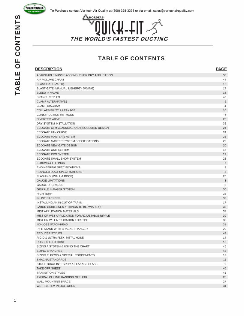
GENERAL ENGINEERING SPECIFICATION FOR LASER QUICK FIT DUCTING
AS MANUFACTURED BY NORDFAB OF THOMASVILLE, NC
DUCT-WORK:
All duct-work shall be of a clamp-together design using a die-formed, rolled edge in which is then joined together by a single lever clamp of similar material. All clamp together ducting shall be of continuous laser welded construction along the longitudinal seam of the rolled form duct with the exception of the 3” which is lock formed. All connections shall have Nitrile seal in clamp for standard installs and a Gortex seal for mist or food grade applications.
Duct material sheet blanks are five feet long, which is then rolled and fused Together with a laser weld process along the longitudinal seam.
The ends of the duct are then pressed in a die to from a rolled bead on each end of the duct. This rolled-end is used for clamping components together as well as reinforcement every 5 feet.
COMPONENT MATERIAL:
Straight duct and other connecting components to be constructed of galvanized sheets produced by the continuous galvanizing process in which conforms to ASTM-A-527, and commercial quality ASTM A-527. Galvanized sheeting is produced with a minimum spangle with coating weight of G-90.
Stainless duct-work is constructed of stainless steel to be 304 cold rolled with a Finish ASTM-A240.
ADDITIONAL INFORMATION:
Duct diameters for QUICK-FIT DUCT as follows:
“Q-F” 3” through 17” available in 1” increments 18” through 24 ” available in 2” increments
2
To Purchase contact Ver-tech Air Quality at (800) 328-3398 or via email: [email protected]
THE WORLD’S FASTEST DUCTINGQuick-Fit
FLA
NG
ED
DU
CT
SP
EC
IFIC
AT
ION
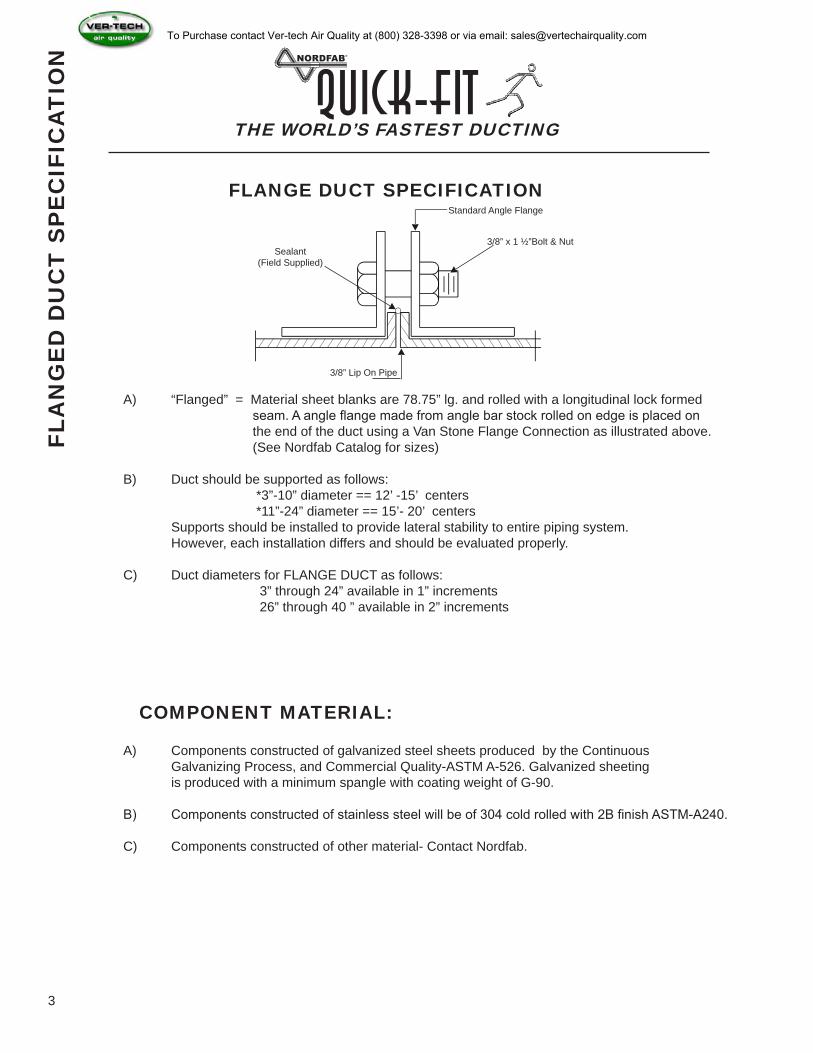
FLANGE DUCT SPECIFICATIONStandard Angle Flange
3/8” x 1 ½”Bolt & Nut
3/8” Lip On Pipe
Sealant (Field Supplied)
A) “Flanged” = Material sheet blanks are 78.75” lg. and rolled with a longitudinal lock formed seam. A angle flange made from angle bar stock rolled on edge is placed on the end of the duct using a Van Stone Flange Connection as illustrated above. (See Nordfab Catalog for sizes)
B) Duct should be supported as follows: *3”-10” diameter == 12’ -15’ centers *11”-24” diameter == 15’- 20’ centers Supports should be installed to provide lateral stability to entire piping system. However, each installation differs and should be evaluated properly.
C) Duct diameters for FLANGE DUCT as follows: 3” through 24” available in 1” increments 26” through 40 ” available in 2” increments
COMPONENT MATERIAL:
A) Components constructed of galvanized steel sheets produced by the Continuous Galvanizing Process, and Commercial Quality-ASTM A-526. Galvanized sheeting is produced with a minimum spangle with coating weight of G-90.
B) Components constructed of stainless steel will be of 304 cold rolled with 2B finish ASTM-A240.
C) Components constructed of other material- Contact Nordfab.
3
To Purchase contact Ver-tech Air Quality at (800) 328-3398 or via email: [email protected]
THE WORLD’S FASTEST DUCTINGQuick-Fit
CLA
MP
DIA
GR
AM
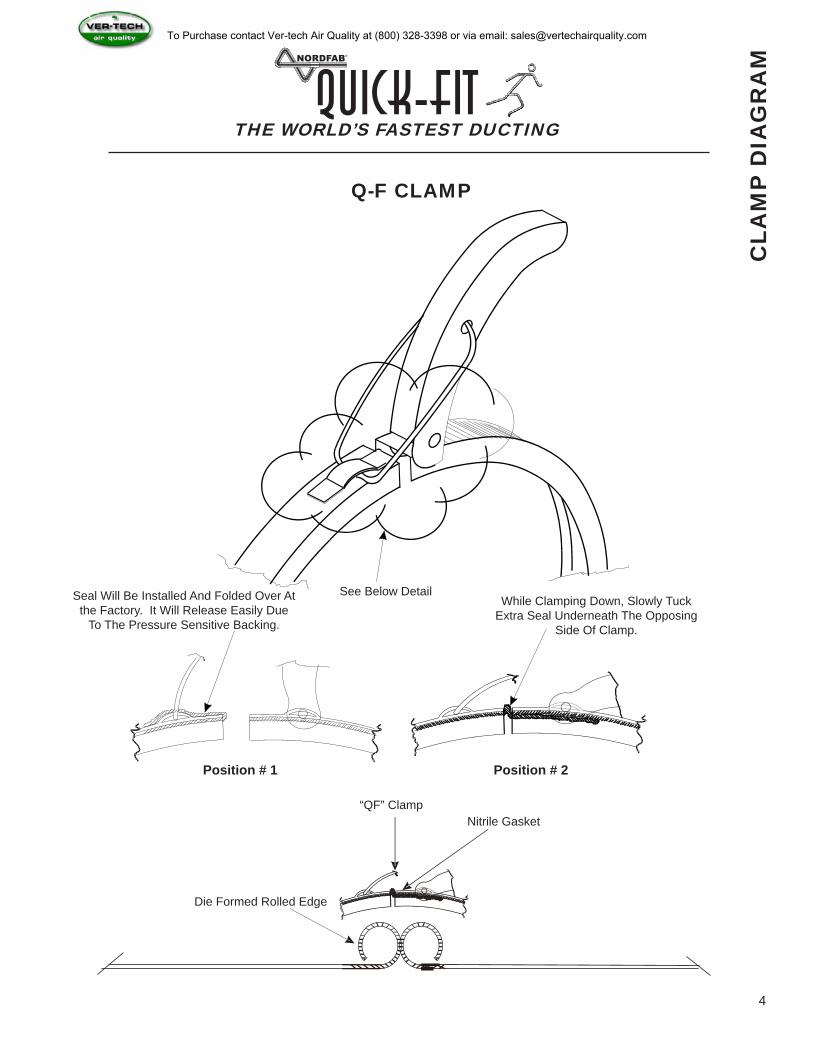
Q-F CLAMP
See Below DetailSeal Will Be Installed And Folded Over At the Factory. It Will Release Easily Due
To The Pressure Sensitive Backing.
While Clamping Down, Slowly Tuck Extra Seal Underneath The Opposing
Side Of Clamp.
Position # 1 Position # 2
“QF” ClampNitrile Gasket
Die Formed Rolled Edge
4
To Purchase contact Ver-tech Air Quality at (800) 328-3398 or via email: [email protected]
THE WORLD’S FASTEST DUCTINGQuick-Fit
CLA
MP
ALT
ER
NA
TIV
ES
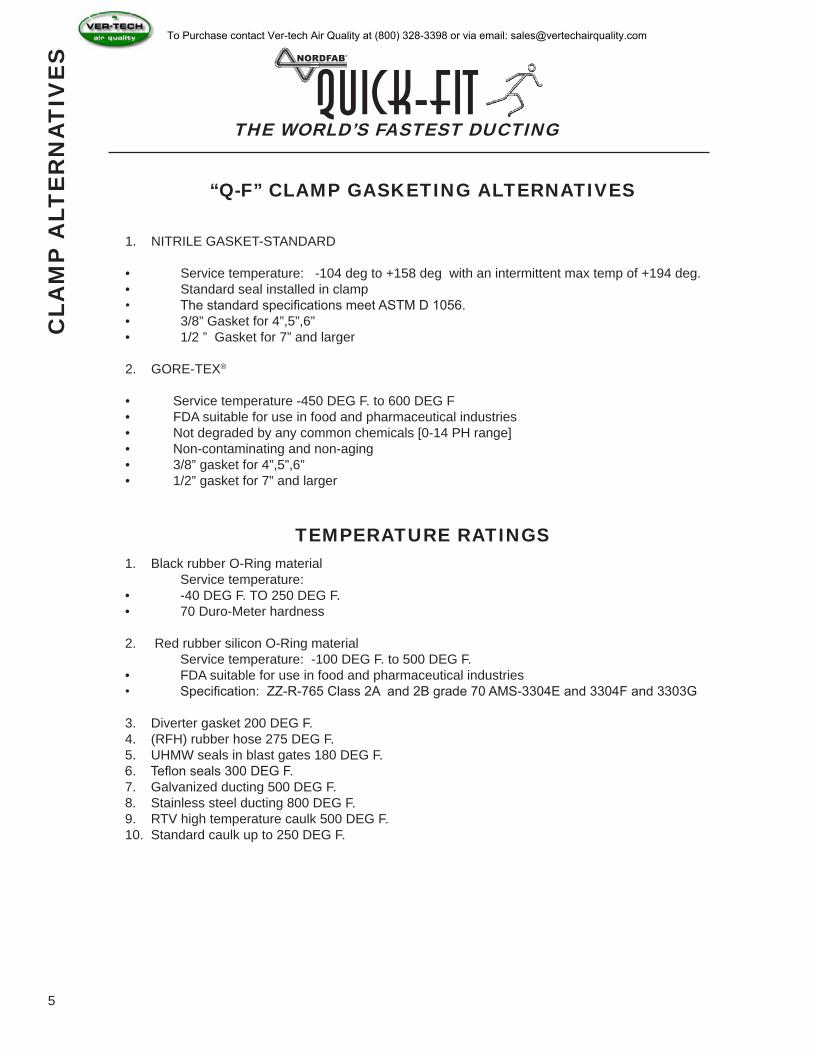
“Q-F” CLAMP GASKETING ALTERNATIVES
1. NITRILE GASKET-STANDARD
• Service temperature: -104 deg to +158 deg with an intermittent max temp of +194 deg.• Standard seal installed in clamp• The standard specifications meet ASTM D 1056.• 3/8” Gasket for 4”,5”,6”• 1/2 ” Gasket for 7” and larger
2. GORE-TEX®
• Service temperature -450 DEG F. to 600 DEG F• FDA suitable for use in food and pharmaceutical industries• Not degraded by any common chemicals [0-14 PH range]• Non-contaminating and non-aging• 3/8” gasket for 4”,5”,6”• 1/2” gasket for 7” and larger
TEMPERATURE RATINGS1. Black rubber O-Ring material Service temperature:• -40 DEG F. TO 250 DEG F.• 70 Duro-Meter hardness
2. Red rubber silicon O-Ring material Service temperature: -100 DEG F. to 500 DEG F.• FDA suitable for use in food and pharmaceutical industries• Specification: ZZ-R-765 Class 2A and 2B grade 70 AMS-3304E and 3304F and 3303G
3. Diverter gasket 200 DEG F.4. (RFH) rubber hose 275 DEG F.5. UHMW seals in blast gates 180 DEG F.6. Teflon seals 300 DEG F.7. Galvanized ducting 500 DEG F.8. Stainless steel ducting 800 DEG F.9. RTV high temperature caulk 500 DEG F.10. Standard caulk up to 250 DEG F.
5
To Purchase contact Ver-tech Air Quality at (800) 328-3398 or via email: [email protected]
THE WORLD’S FASTEST DUCTINGQuick-Fit
CO
NS
TR
UC
TIO
N M
ET
HO
DS
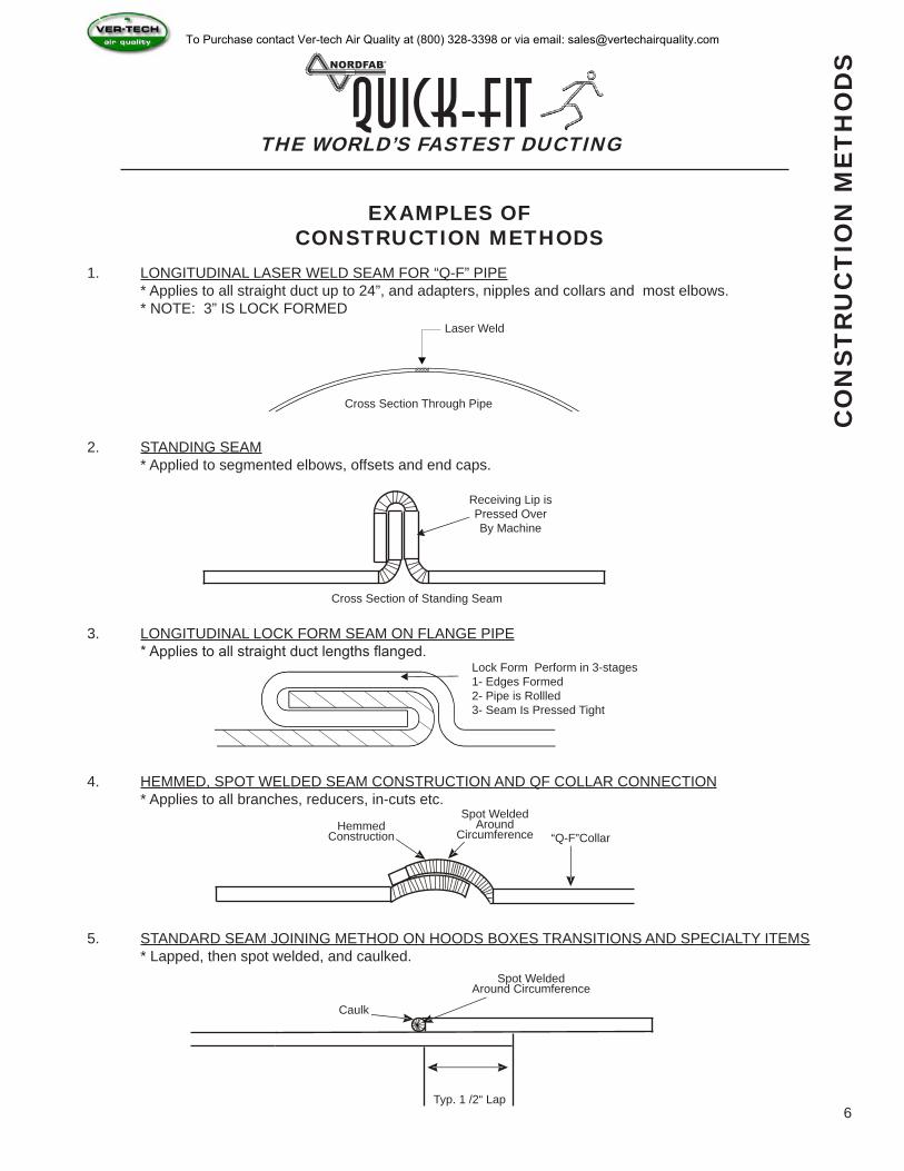
EXAMPLES OF CONSTRUCTION METHODS
1. LONGITUDINAL LASER WELD SEAM FOR “Q-F” PIPE * Applies to all straight duct up to 24”, and adapters, nipples and collars and most elbows. * NOTE: 3” IS LOCK FORMED
Laser Weld
Cross Section Through Pipe
2. STANDING SEAM * Applied to segmented elbows, offsets and end caps.
3. LONGITUDINAL LOCK FORM SEAM ON FLANGE PIPE * Applies to all straight duct lengths flanged.
4. HEMMED, SPOT WELDED SEAM CONSTRUCTION AND QF COLLAR CONNECTION * Applies to all branches, reducers, in-cuts etc.
5. STANDARD SEAM JOINING METHOD ON HOODS BOXES TRANSITIONS AND SPECIALTY ITEMS * Lapped, then spot welded, and caulked.
Receiving Lip isPressed Over By Machine
Lock Form Perform in 3-stages1- Edges Formed2- Pipe is Rollled3- Seam Is Pressed Tight
Cross Section of Standing Seam
“Q-F”CollarHemmed
Construction
Spot Welded Around
Circumference
Caulk
Spot Welded Around Circumference
Typ. 1 /2“ Lap 6
To Purchase contact Ver-tech Air Quality at (800) 328-3398 or via email: [email protected]
ANGLE IN DEGREES NUMBER OF GORES @ 15DEG0 TO 30 3
31 TO 45 446 TO 60 5
THE WORLD’S FASTEST DUCTINGQuick-Fit
E
LBO
WS
FIT
TIN
GS
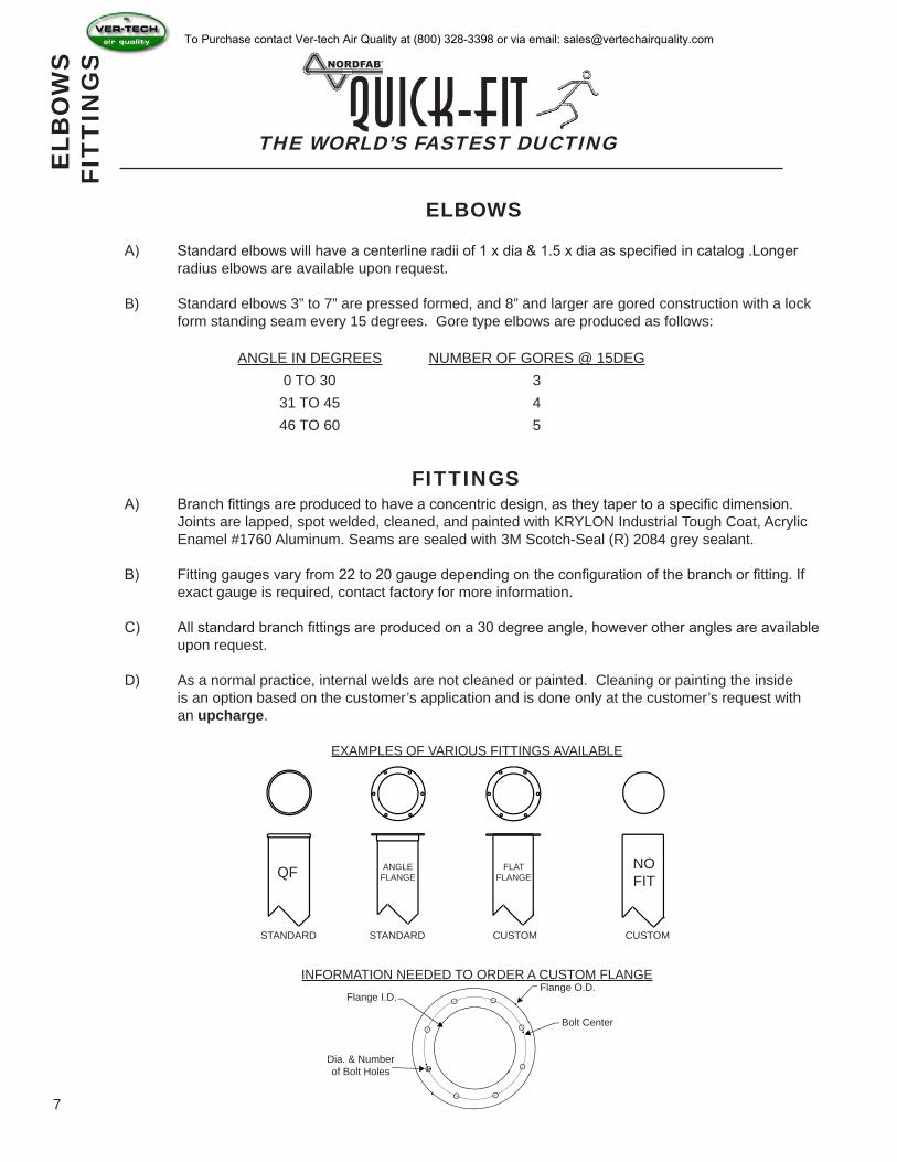
ELBOWS
FITTINGS
A) Standard elbows will have a centerline radii of 1 x dia & 1.5 x dia as specified in catalog .Longer radius elbows are available upon request.
B) Standard elbows 3” to 7” are pressed formed, and 8” and larger are gored construction with a lock form standing seam every 15 degrees. Gore type elbows are produced as follows:
A) Branch fittings are produced to have a concentric design, as they taper to a specific dimension. Joints are lapped, spot welded, cleaned, and painted with KRYLON Industrial Tough Coat, Acrylic Enamel #1760 Aluminum. Seams are sealed with 3M Scotch-Seal (R) 2084 grey sealant.
B) Fitting gauges vary from 22 to 20 gauge depending on the configuration of the branch or fitting. If exact gauge is required, contact factory for more information.
C) All standard branch fittings are produced on a 30 degree angle, however other angles are available upon request.
D) As a normal practice, internal welds are not cleaned or painted. Cleaning or painting the inside is an option based on the customer’s application and is done only at the customer’s request with an upcharge.
QF ANGLE FLANGE
NOFIT
FLAT FLANGE
STANDARD STANDARD CUSTOM CUSTOM
EXAMPLES OF VARIOUS FITTINGS AVAILABLE
INFORMATION NEEDED TO ORDER A CUSTOM FLANGEFlange O.D.
Bolt Center
Flange I.D.
Dia. & Numberof Bolt Holes
7
To Purchase contact Ver-tech Air Quality at (800) 328-3398 or via email: [email protected]
ELBOW DIAMETER GALV STD GAUGE SS STD GAUGE ONE GAUGE
UPGRADEMAX LSB
STYLE ELBOW
3” 24 14 TUBED N/A N/A
4” 24 14 TUBED N/A N/A
5” 24 14 TUBED N/A N/A
6” 24 14 TUBED N/A N/A
7” 24 22 20 16
8” 22 22 20 16
9” 22 22 20 16
10” 22 22 20 16
11” 22 22 20 16
12” 22 22 20 16
13” 20 20 18 16
14” 20 20 18 16
15” 20 20 18 16
16” 20 20 18 16
17” 20 20 18 16
18” 20 20 18 16
19” 20 20 18 16
20” 20 20 18 16
21” 20 20 18 16
22” 20 20 18 16
23” 20 20 18 16
24” 20 20 18 16
26” 18 18 18 16
28” 18 18 18 16
30” 18 18 18 16
32” 18 18 18 16
34” 18 18 18 16
36” 18 18 16 16
38” 18 18 16 16
40” 18 18 16 16
DIAPIPE STD
GAUGENIPPLE STD
GAUGEMAX GALV GA MAX SS GA
UPGRADEID OD ID OD PIPE NIPPLE
3” 3.05 3.11 22 3.16 3.22 23 N/A N/A N/A
4” 3.86 3.92 22 3.98 4.04 22 22 22 22
5” 4.86 4.92 22 4.98 5.04 22 22 22 22
6” 5.86 5.92 22 5.98 6.04 22 22 22 22
7” 6.9 6.96 22 7.01 7.063 22 20 20 20
8” 7.9 7.9 6 22 8.01 8.063 22 18 18 20
9” 8.9 9.5 22 9.01 9.063 22 18 18 20
10” 9.94 10 22 10.05 10.067 22 18 18 20
11” 11 11.06 22 11.12 11.18 22 18 18 18
12” 12 12.06 22 12.12 12.18 22 18 18 18
13” 13 13.074 20 13.12 13.19 20 18 18 18
14” 14 14.074 20 14.12 14.19 20 18 18 18
15” 15 15.074 20 15.12 15.19 20 18 18 18
16” 16 16.074 20 16.12 16.19 20 18 18 18
17” 17 17.074 20 17.07 17.15 20 18 18 18
18” 18 18.074 20 18.12 18.19 20 18 18 18
19” 19 19.074 20 19.12 19.19 20 18 18 18
20” 20 20.074 20 20.12 20.19 20 18 18 18
21” 21 21.074 20 21.12 21.19 20 18 18 18
22” 22 22.074 20 22.12 22.19 20 18 18 18
23” 23 23.074 20 23.12 23.19 20 18 18 18
24” 24 24.074 20 24.12 24.19 20 18 18 18
THE WORLD’S FASTEST DUCTINGQuick-Fit
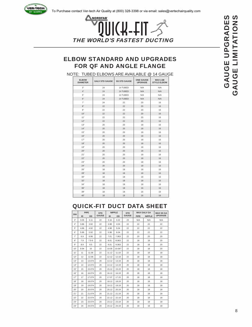
ELBOW STANDARD AND UPGRADES FOR QF AND ANGLE FLANGE
GA
UG
E U
PG
RA
DE
SG
AU
GE
LIM
ITA
TIO
NS
NOTE: TUBED ELBOWS ARE AVAILABLE @ 14 GAUGE
8
QUICK-FIT DUCT DATA SHEET
To Purchase contact Ver-tech Air Quality at (800) 328-3398 or via email: [email protected]

THE WORLD’S FASTEST DUCTINGQuick-Fit
9
Duct SizeAvg. leakage per 100 ft.
SMACNA CLASS5” SP IO” SP
4” 6” 5 CFM 6 CFM 3
7” 10” 2.5 CFM 3.5 CFM 3
11” 24” 2 CFM 4 CFM 3
ST
RU
CT
UR
AL
INT
EG
RIT
Y &
LE
AK
AG
E C
LAS
S
STRUCTURAL INTEGRITY
NORDFAB150 Transit Avenue P.O. Box 190
Thomasville, North Carolina 27361-0190Tel.: (800) 532-0830 Fax: (336) 889-7873
July 16, 2003
To whom it may concern
Reference: Structural integrity of “QF” Piping System
The Nordfab Laser “Quick-Fit” Piping System has been used in many different industrial applications, and under various negative static pressures.
The typical design range we see in our applications, range from -2” wg to -28 wg, however we have some systems operating at vacuums of -32” wg to - 42” wg under normal operating parameters. Should these levels of static pressure be required, we suggest an alternative seal be used in the clamp such as the white Gortex Seal. This increases the sealing properties on the connection joint.
Please take into account that our pipe comes in 5’ lengths with a rolled lip on each end, thus providing reinforcement every 5’, which presents a sound structural design that should be stronger than any pipe in its class.
Sincerely,Niels PedersenPresident
All fit together ducting systems allow for some degree of leakage. ‘Q-F” ducting is no exception and is not sold as an airtight system. In addition to standard Nitrile gasket, NORDFAB offers special clamp gasket material for high heat and enhanced sealing. Further, the applying of sealants to the individual rolled ends can enhance the tightness of the system. However, the “Q-F” system is sold as a quick way of installing and modifying duct-work while at the same time retaining the usability of each component. In short, “Q-F” is meant to be able to be taken apart, re-assembled, stored or moved. Completely eliminating the possibility for leakage jeopardizes the inherent benefits of the duct.
While NORDFAB is currently unaware of any method of evaluating dust collection piping alone, the following data is presented using the criteria for all duct, including HVAC. This data is presented only for the purpose of indicating acceptability of the “Q-F” in dust/fume removal in a negative pressure situations and should not be confused with the ducting that uses tape or gaskets as sealant in the positive conveyance of air.
LEAKAGE CLASS DETERMINED IN ACCORDANCE WITH SMACNA
To Purchase contact Ver-tech Air Quality at (800) 328-3398 or via email: [email protected]
Dia Inches 3 WG 5 WG 7.5 WG 10 WG 15 WG 20 WG 25 WG 30 WG
4 0.20 0.25 0.30 0.30 0.35 0.50 0.60 0.80
5 0.20 0.25 0.30 0.30 0.35 0.50 0.60 0.80
6 0.20 0.25 0.30 0.30 0.35 0.50 0.60 0.80
7 0.20 0.25 0.30 0.30 0.35 0.50 0.60 0.80
8 0.20 0.25 0.30 0.30 0.35 0.50 0.60 0.80
9 0.20 0.25 0.30 0.30 0.35 0.50 0.60 0.80
10 0.20 0.25 0.30 0.30 0.35 0.50 0.60 0.80
12 0.30 0.30 0.40 0.40 0.40 0.60 0.70 0.90
14 0.30 0.30 0.50 0.70 0.80 0.80 0.90 1.10
16 0.30 0.40 0.60 0.70 1.00 1.10 1.20 1.40
18 0.40 0.40 0.70 0.80 1.10 1.30 1.50 1.70
20 0.40 0.60 0.80 0.90 1.20 1.50 1.70 2.00
22 0.40 0.60 0.80 1.10 1.40 1.50 2.00 2.20
THE WORLD’S FASTEST DUCTINGQuick-Fit
COLLAPSIBILITY & LEAKAGE DATA
CO
LLA
PS
IBIL
ITY
& L
EA
KA
GE
DA
TA
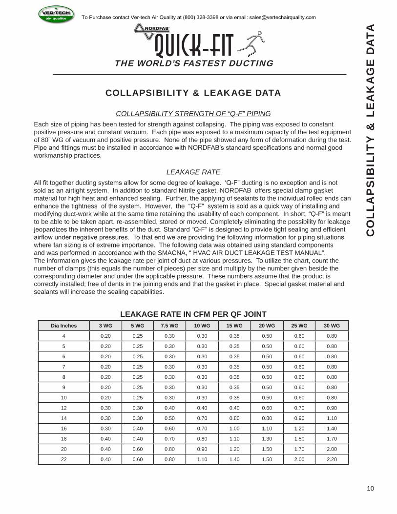
COLLAPSIBILITY STRENGTH OF “Q-F” PIPINGEach size of piping has been tested for strength against collapsing. The piping was exposed to constant positive pressure and constant vacuum. Each pipe was exposed to a maximum capacity of the test equipment of 80” WG of vacuum and positive pressure. None of the pipe showed any form of deformation during the test. Pipe and fittings must be installed in accordance with NORDFAB’s standard specifications and normal good workmanship practices.
LEAKAGE RATEAll fit together ducting systems allow for some degree of leakage. ‘Q-F” ducting is no exception and is not sold as an airtight system. In addition to standard Nitrile gasket, NORDFAB offers special clamp gasket material for high heat and enhanced sealing. Further, the applying of sealants to the individual rolled ends can enhance the tightness of the system. However, the “Q-F” system is sold as a quick way of installing and modifying duct-work while at the same time retaining the usability of each component. In short, “Q-F” is meant to be able to be taken apart, re-assembled, stored or moved. Completely eliminating the possibility for leakage jeopardizes the inherent benefits of the duct. Standard “Q-F” is designed to provide tight sealing and efficient airflow under negative pressures. To that end we are providing the following information for piping situations where fan sizing is of extreme importance. The following data was obtained using standard components and was performed in accordance with the SMACNA, “ HVAC AIR DUCT LEAKAGE TEST MANUAL”. The information gives the leakage rate per joint of duct at various pressures. To utilize the chart, count the number of clamps (this equals the number of pieces) per size and multiply by the number given beside the corresponding diameter and under the applicable pressure. These numbers assume that the product is correctly installed; free of dents in the joining ends and that the gasket in place. Special gasket material and sealants will increase the sealing capabilities.
LEAKAGE RATE IN CFM PER QF JOINT
10
To Purchase contact Ver-tech Air Quality at (800) 328-3398 or via email: [email protected]

SMACNA STANDARDS NORDFAB OFFERS
SIZES GAUGE REINFORCEMENT STANDARD OPTIONAL
4”-6 22 NONE 22 GA 22 GA
8” 22 NONE 22 GA 18 GA
10” 20 NONE 22 GA 18 GA
11” 20 NONE 22 GA 18 GA
12” 20 NONE 22 GA 18 GA
13” 20 NONE 20 GA 18 GA
14” 18 NONE 20 GA 18 GA
15” 18 NONE 20 GA 18 GA
16” 18 NONE 20 GA 18 GA
17” 18 NONE 20 GA 18 GA
18” 16 NONE 20 GA 16 GA
20” 16 NONE 20 GA 16 GA
22” 18 12’ ON CENTER 20 GA 16 GA
24” 18 12’ ON CENTER 20 GA 16 GA
THE WORLD’S FASTEST DUCTINGQuick-Fit
11
SMACNA ROUND INDUSTRIAL DUCT CONSTRUCTION STANDARDS OF 1999
The following gauge thickness reinforcement information is recommended for Class 2 Duct System.Subjected to a negative pressure of 10” water gauge.
Class 2 is defined as including applications with moderately abrasive particles in light concentrations: i.e. buffing, polishing, woodworking, grain dust etc.
Understanding that Nordfab duct comes in 5’ maximum lengths and has the rolled edge on both ends, it seems that the beads at the joints would act as reinforcement and by the use of the clamp the pipe is banded every 5’. This appears to be the only question that could be a gray area of our acceptance in the specifications. Velocities of 4500-5500 FPM and static pressures to 25” water gauge are within design criteria and our duct was originally and still is designed for the wood industry.
SM
AC
NA
STA
ND
AR
DS
To Purchase contact Ver-tech Air Quality at (800) 328-3398 or via email: [email protected]
THE WORLD’S FASTEST DUCTINGQuick-Fit
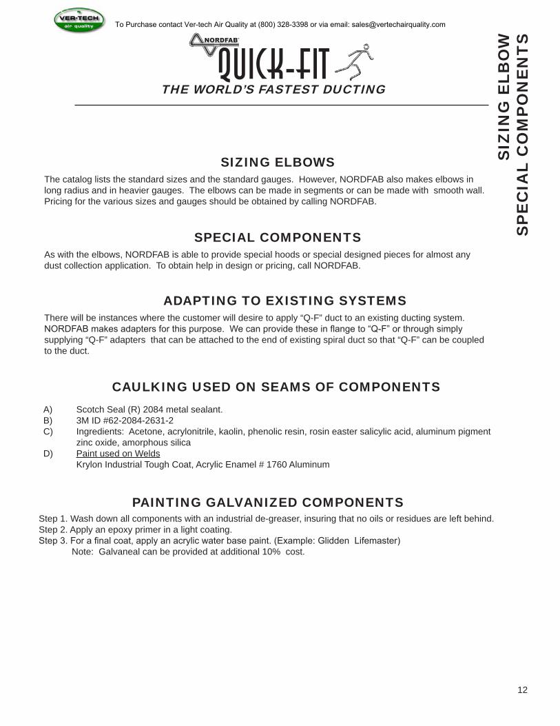
SIZING ELBOWSThe catalog lists the standard sizes and the standard gauges. However, NORDFAB also makes elbows in long radius and in heavier gauges. The elbows can be made in segments or can be made with smooth wall. Pricing for the various sizes and gauges should be obtained by calling NORDFAB.
SPECIAL COMPONENTSAs with the elbows, NORDFAB is able to provide special hoods or special designed pieces for almost any dust collection application. To obtain help in design or pricing, call NORDFAB.
ADAPTING TO EXISTING SYSTEMSThere will be instances where the customer will desire to apply “Q-F” duct to an existing ducting system. NORDFAB makes adapters for this purpose. We can provide these in flange to “Q-F” or through simply supplying “Q-F” adapters that can be attached to the end of existing spiral duct so that “Q-F” can be coupled to the duct.
CAULKING USED ON SEAMS OF COMPONENTSA) Scotch Seal (R) 2084 metal sealant.B) 3M ID #62-2084-2631-2C) Ingredients: Acetone, acrylonitrile, kaolin, phenolic resin, rosin easter salicylic acid, aluminum pigment zinc oxide, amorphous silicaD) Paint used on Welds Krylon Industrial Tough Coat, Acrylic Enamel # 1760 Aluminum
PAINTING GALVANIZED COMPONENTSStep 1. Wash down all components with an industrial de-greaser, insuring that no oils or residues are left behind.Step 2. Apply an epoxy primer in a light coating.Step 3. For a final coat, apply an acrylic water base paint. (Example: Glidden Lifemaster) Note: Galvaneal can be provided at additional 10% cost.
SIZ
ING
ELB
OW
SP
EC
IAL
CO
MP
ON
EN
TS
12
To Purchase contact Ver-tech Air Quality at (800) 328-3398 or via email: [email protected]
THE WORLD’S FASTEST DUCTINGQuick-Fit
13
RUBBER FLEXIBLE HOSE
RU
BB
ER
FLE
XIB
LE H
OS
E
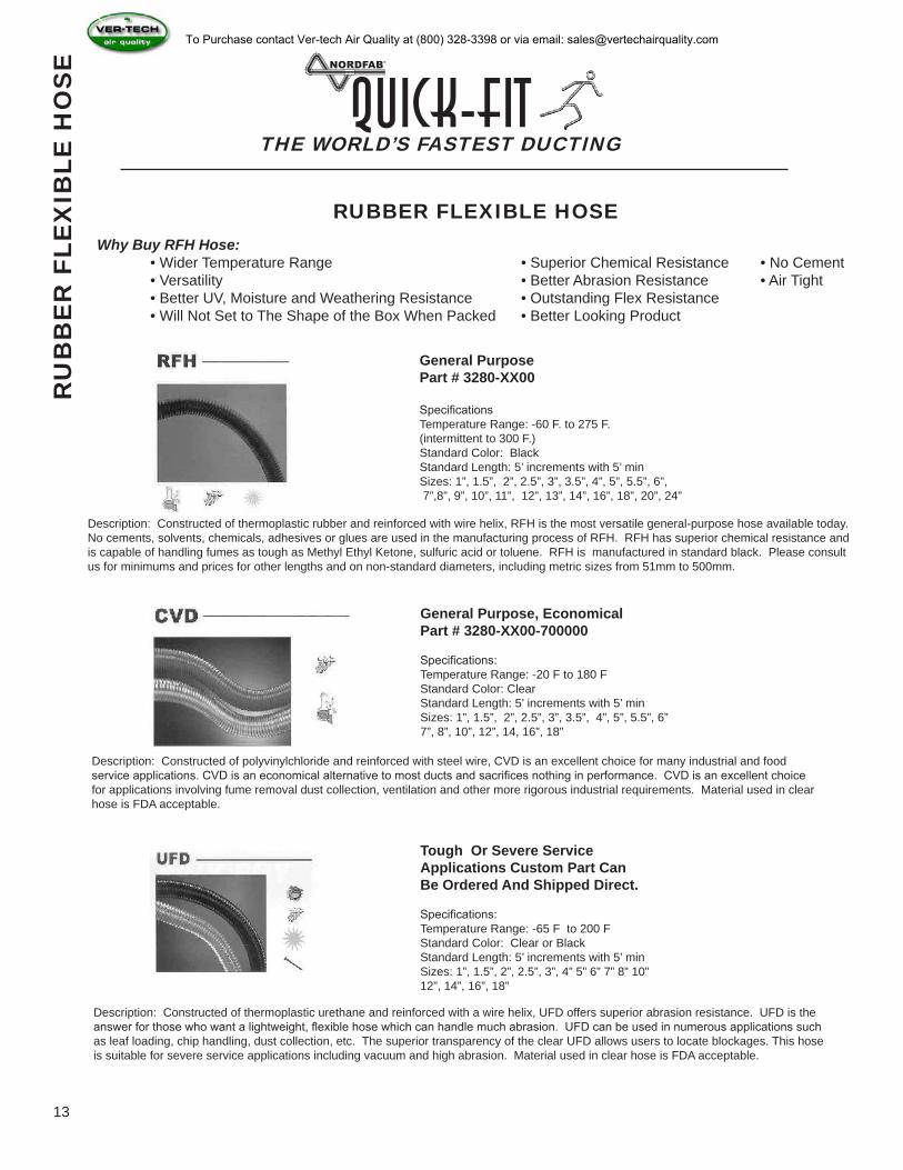
Why Buy RFH Hose: • Wider Temperature Range • Superior Chemical Resistance • No Cement • Versatility • Better Abrasion Resistance • Air Tight • Better UV, Moisture and Weathering Resistance • Outstanding Flex Resistance • Will Not Set to The Shape of the Box When Packed • Better Looking Product
General Purpose Part # 3280-XX00
SpecificationsTemperature Range: -60 F. to 275 F.(intermittent to 300 F.)Standard Color: BlackStandard Length: 5’ increments with 5’ minSizes: 1”, 1.5”, 2”, 2.5”, 3”, 3.5”, 4”, 5”, 5.5”, 6”, 7”,8”, 9”, 10”, 11”, 12”, 13”, 14”, 16”, 18”, 20”, 24”
Description: Constructed of thermoplastic rubber and reinforced with wire helix, RFH is the most versatile general-purpose hose available today. No cements, solvents, chemicals, adhesives or glues are used in the manufacturing process of RFH. RFH has superior chemical resistance and is capable of handling fumes as tough as Methyl Ethyl Ketone, sulfuric acid or toluene. RFH is manufactured in standard black. Please consult us for minimums and prices for other lengths and on non-standard diameters, including metric sizes from 51mm to 500mm.
General Purpose, EconomicalPart # 3280-XX00-700000
Specifications:Temperature Range: -20 F to 180 FStandard Color: ClearStandard Length: 5’ increments with 5’ minSizes: 1”, 1.5”, 2”, 2.5”, 3”, 3.5”, 4”, 5”, 5.5”, 6”7”, 8”, 10”, 12”, 14, 16”, 18”
Description: Constructed of polyvinylchloride and reinforced with steel wire, CVD is an excellent choice for many industrial and food service applications. CVD is an economical alternative to most ducts and sacrifices nothing in performance. CVD is an excellent choice for applications involving fume removal dust collection, ventilation and other more rigorous industrial requirements. Material used in clear hose is FDA acceptable.
Tough Or Severe Service Applications Custom Part Can Be Ordered And Shipped Direct.
Specifications:Temperature Range: -65 F to 200 FStandard Color: Clear or BlackStandard Length: 5’ increments with 5’ minSizes: 1”, 1.5”, 2”, 2.5”, 3”, 4” 5” 6” 7” 8” 10” 12”, 14”, 16”, 18”
Description: Constructed of thermoplastic urethane and reinforced with a wire helix, UFD offers superior abrasion resistance. UFD is the answer for those who want a lightweight, flexible hose which can handle much abrasion. UFD can be used in numerous applications such as leaf loading, chip handling, dust collection, etc. The superior transparency of the clear UFD allows users to locate blockages. This hose is suitable for severe service applications including vacuum and high abrasion. Material used in clear hose is FDA acceptable.
To Purchase contact Ver-tech Air Quality at (800) 328-3398 or via email: [email protected]

Inside Dia. (Inches)
Appox. Outside Dia.
(Inches)
Min. CLR Bend Radius
Appox. Weight Per Foot (LBS)
Inside Dia. (Inches)
Appox. Outside Dia.
(Inches)
Min. CLR Bend Radius
Appox. Weight Per Foot (LBS)
1 1/2 1 3/4 5.5 0.85 6 6 1/4 21.5 3.45
2 2 1/4 6.5 1.15 7 7 1/4 24.0 4.03
2 1/2 2 3/4 8.5 1.44 8 8 1/4 27.5 4.60
3 3 1/4 10.5 1.73 9 9 1/4 29.5 5.18
3 1/2 3 3/4 12.5 2.01 10 10 1/4 31.5 5.75
4 4 1/4 13.5 2.30 12 12 1/4 38.0 6.90
5 5 16.5 2.86 14 14 1/4 42.5 8.05
Inside Dia. (Inches)
Min. CLR Bend Radius
Appox. Weight Per Foot (LBS)
Inside Dia. (Inches)
Min. CLR Bend Radius
Appox. Weight Per Foot (LBS)
3 8.13 1.04 6 15.63 2.00
4 9.38 1.20 7 16.50 2.80
5 12.38 1.68 8 19.75 3.20
THE WORLD’S FASTEST DUCTINGQuick-Fit
14
RIGID METAL FLEX HOSE
ULTRA FLEX METAL HOSE
Part # 3281-XX00
Part # 3283-XX00
MEDIUM-HEAVY GALVANIZED OR STAINLESS .017- .020 Strip Thickness
Manufactured in sizes ranging from 3”dia thru 8” dia of stainless steel or galvanized.Some Applications would include Air Handling, and Dust Collection.
Square Lock: ID Tolerance: +1/4 “ , - 0 Specification: 3”-6” manufactured out of .019 material 7”-8” manufactured out of .024 material
RIGID AND ULTRA FLEX STEEL HOSE CONFIGURATIONSSteel Flex Hose With Raw Ends (Standard) Steel Flex Hose With Q-F Ends (Custom)
Steel Flex Hose With Raw Pipe Ends (Custom)Steel Flex Hose With Flange Ends (Custom)
NOTE: When ordering steel hose, you have the option of having the hose fitted with several different style end fittings in any number of combinations. Raw hose is priced per foot, and sold only in 5 Ft. increments. Contact your sales rep for pricing on specific lengths and end fittings.
R
IGID
& U
LTR
A F
LEX
ME
TAL
HO
SE
To Purchase contact Ver-tech Air Quality at (800) 328-3398 or via email: [email protected]
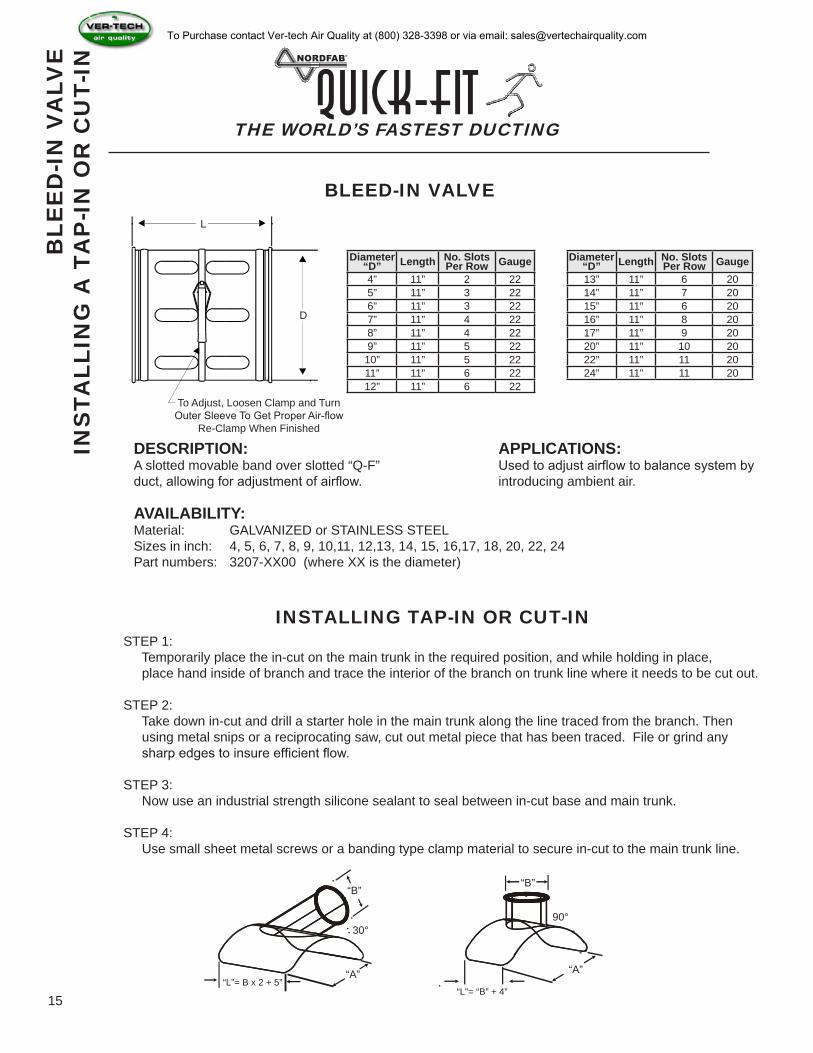
Diameter“D” Length No. Slots
Per Row Gauge Diameter“D” Length No. Slots
Per Row Gauge4” 11” 2 22 13” 11” 6 205” 11” 3 22 14” 11” 7 206” 11” 3 22 15” 11” 6 207” 11” 4 22 16” 11” 8 208” 11” 4 22 17” 11” 9 209” 11” 5 22 20” 11” 10 20
10” 11” 5 22 22” 11” 11 2011” 11” 6 22 24” 11” 11 2012” 11” 6 22
THE WORLD’S FASTEST DUCTINGQuick-Fit
15
To Adjust, Loosen Clamp and TurnOuter Sleeve To Get Proper Air-flow
Re-Clamp When Finished
D
L
“B”
“L”= B x 2 + 5”“A”
30°
“B”
“L”= “B” + 4”
“A”
90°
BLEED-IN VALVE
DESCRIPTION:A slotted movable band over slotted “Q-F” duct, allowing for adjustment of airflow.
APPLICATIONS:Used to adjust airflow to balance system by introducing ambient air.
AVAILABILITY:Material: GALVANIZED or STAINLESS STEELSizes in inch: 4, 5, 6, 7, 8, 9, 10,11, 12,13, 14, 15, 16,17, 18, 20, 22, 24Part numbers: 3207-XX00 (where XX is the diameter)
INSTALLING TAP-IN OR CUT-INSTEP 1: Temporarily place the in-cut on the main trunk in the required position, and while holding in place, place hand inside of branch and trace the interior of the branch on trunk line where it needs to be cut out.
STEP 2: Take down in-cut and drill a starter hole in the main trunk along the line traced from the branch. Then using metal snips or a reciprocating saw, cut out metal piece that has been traced. File or grind any sharp edges to insure efficient flow.
STEP 3: Now use an industrial strength silicone sealant to seal between in-cut base and main trunk.
STEP 4: Use small sheet metal screws or a banding type clamp material to secure in-cut to the main trunk line.
BLE
ED
-IN
VA
LVE
IN
STA
LLIN
G A
TA
P-I
N O
R C
UT-
IN
To Purchase contact Ver-tech Air Quality at (800) 328-3398 or via email: [email protected]
THE WORLD’S FASTEST DUCTINGQuick-Fit
16
BLA
ST
GA
TE
(A
UTO
)
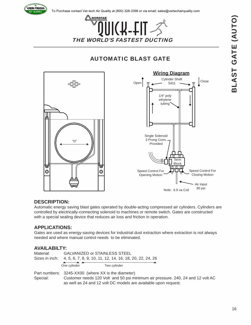
AUTOMATIC BLAST GATE
“D”
Open CloseCylinder ShaftSd11
1/4” poly ethylenetubing
Single Solenoid3 Prong Conn.
Provided
Speed Control For Closing Motion
Speed Control ForOpening Motion
Air Input80 psiNote: 6.9 va Coil
Term Block
1
2
3
4
5
BlkWG
Wiring Diagram
DESCRIPTION:Automatic energy saving blast gates operated by double-acting compressed air cylinders. Cylinders are controlled by electrically-connecting solenoid to machines or remote switch. Gates are constructed with a special sealing device that reduces air loss and friction in operation.
APPLICATIONS:Gates are used as energy-saving devices for industrial dust extraction where extraction is not always needed and where manual control needs to be eliminated.
AVAILABILTY:Material: GALVANIZED or STAINLESS STEELSizes in inch: 4, 5, 6, 7, 8, 9, 10, 11, 12, 14, 16, 18, 20, 22, 24, 26
Part numbers: 3245-XX00 (where XX is the diameter)Special: Customer needs 120 Volt and 50 psi minimum air pressure. 240, 24 and 12 volt AC as well as 24 and 12 volt DC models are available upon request.
One cylinder Two cylinder
To Purchase contact Ver-tech Air Quality at (800) 328-3398 or via email: [email protected]
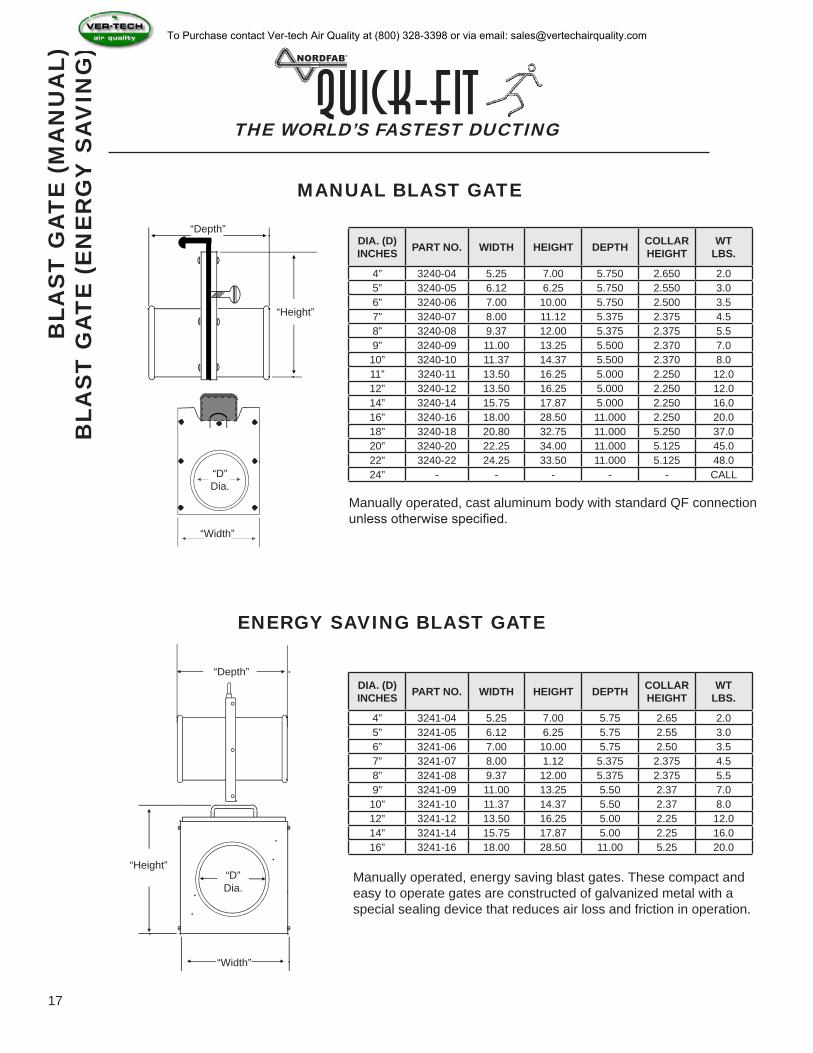
DIA. (D) INCHES PART NO. WIDTH HEIGHT DEPTH COLLAR
HEIGHTWT
LBS.
4” 3240-04 5.25 7.00 5.750 2.650 2.05” 3240-05 6.12 6.25 5.750 2.550 3.06” 3240-06 7.00 10.00 5.750 2.500 3.57” 3240-07 8.00 11.12 5.375 2.375 4.58” 3240-08 9.37 12.00 5.375 2.375 5.59” 3240-09 11.00 13.25 5.500 2.370 7.0
10” 3240-10 11.37 14.37 5.500 2.370 8.011” 3240-11 13.50 16.25 5.000 2.250 12.012” 3240-12 13.50 16.25 5.000 2.250 12.014” 3240-14 15.75 17.87 5.000 2.250 16.016” 3240-16 18.00 28.50 11.000 2.250 20.018” 3240-18 20.80 32.75 11.000 5.250 37.020” 3240-20 22.25 34.00 11.000 5.125 45.022” 3240-22 24.25 33.50 11.000 5.125 48.024” - - - - - CALL
DIA. (D) INCHES PART NO. WIDTH HEIGHT DEPTH COLLAR
HEIGHTWT
LBS.
4” 3241-04 5.25 7.00 5.75 2.65 2.05” 3241-05 6.12 6.25 5.75 2.55 3.06” 3241-06 7.00 10.00 5.75 2.50 3.57” 3241-07 8.00 1.12 5.375 2.375 4.58” 3241-08 9.37 12.00 5.375 2.375 5.59” 3241-09 11.00 13.25 5.50 2.37 7.0
10” 3241-10 11.37 14.37 5.50 2.37 8.012” 3241-12 13.50 16.25 5.00 2.25 12.014” 3241-14 15.75 17.87 5.00 2.25 16.016” 3241-16 18.00 28.50 11.00 5.25 20.0
THE WORLD’S FASTEST DUCTINGQuick-Fit
17
BLA
ST
GA
TE
(M
AN
UA
L)B
LAS
T G
AT
E (
EN
ER
GY
SA
VIN
G)
MANUAL BLAST GATE
“Width”
Manually operated, cast aluminum body with standard QF connection unless otherwise specified.
“Depth”
“Height”
“D”Dia.
“Width”
“Depth”
“Height”“D”Dia.
ENERGY SAVING BLAST GATE
Manually operated, energy saving blast gates. These compact and easy to operate gates are constructed of galvanized metal with a special sealing device that reduces air loss and friction in operation.
To Purchase contact Ver-tech Air Quality at (800) 328-3398 or via email: [email protected]
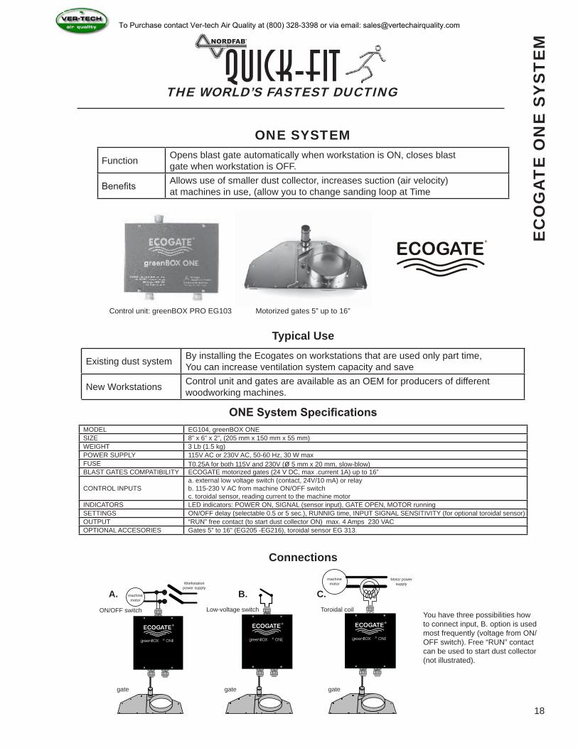
Function Opens blast gate automatically when workstation is ON, closes blast gate when workstation is OFF.
Benefits Allows use of smaller dust collector, increases suction (air velocity) at machines in use, (allow you to change sanding loop at Time
Existing dust system By installing the Ecogates on workstations that are used only part time, You can increase ventilation system capacity and save
New Workstations Control unit and gates are available as an OEM for producers of different woodworking machines.
MODEL EG104, greenBOX ONESIZE 8” x 6” x 2”, (205 mm x 150 mm x 55 mm)WEIGHT 3 Lb (1.5 kg)POWER SUPPLY 115V AC or 230V AC, 50-60 Hz, 30 W maxFUSE T0.25A for both 115V and 230V (ø 5 mm x 20 mm, slow-blow)BLAST GATES COMPATIBILITY ECOGATE motorized gates (24 V DC, max .current 1A) up to 16”
CONTROL INPUTSa. external low voltage switch (contact, 24V/10 mA) or relayb. 115-230 V AC from machine ON/OFF switchc. toroidal sensor, reading current to the machine motor
INDICATORS LED indicators: POWER ON, SIGNAL (sensor input), GATE OPEN, MOTOR runningSETTINGS ON/OFF delay (selectable 0.5 or 5 sec.), RUNNIG time, INPUT SIGNAL SENSITIVITY (for optional toroidal sensor)OUTPUT “RUN” free contact (to start dust collector ON) max. 4 Amps 230 VACOPTIONAL ACCESORIES Gates 5” to 16” (EG205 -EG216), toroidal sensor EG 313.
greenBOX ® ONEgreenBOX ® ONEgreenBOX ® ONE
THE WORLD’S FASTEST DUCTINGQuick-Fit
18
EC
OG
AT
E O
NE
SY
ST
EM
ONE SYSTEM
Control unit: greenBOX PRO EG103 Motorized gates 5” up to 16”
Typical Use
ONE System Specifications
Connections
ON/OFF switch
A. B. C.Low-voltage switch Toroidal coil
machine motor
Workstation power supply
gate gate gate
machine motor
Motor power supply
You have three possibilities how to connect input, B. option is used most frequently (voltage from ON/OFF switch). Free “RUN” contact can be used to start dust collector (not illustrated).
To Purchase contact Ver-tech Air Quality at (800) 328-3398 or via email: [email protected]
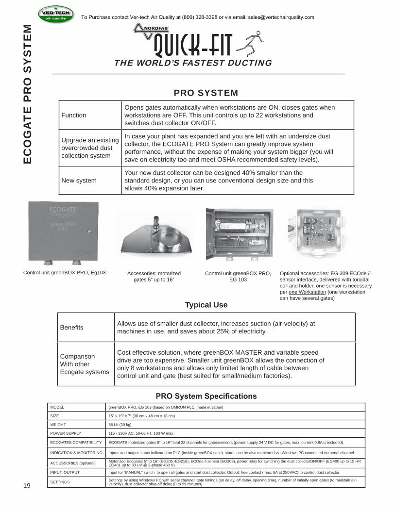
FunctionOpens gates automatically when workstations are ON, closes gates when workstations are OFF. This unit controls up to 22 workstations and switches dust collector ON/OFF.
Upgrade an existing overcrowded dust collection system
In case your plant has expanded and you are left with an undersize dust collector, the ECOGATE PRO System can greatly improve system performance, without the expense of making your system bigger (you will save on electricity too and meet OSHA recommended safety levels).
New systemYour new dust collector can be designed 40% smaller than the standard design, or you can use conventional design size and this allows 40% expansion later.
Benefits Allows use of smaller dust collector, increases suction (air-velocity) at machines in use, and saves about 25% of electricity.
ComparisonWith other Ecogate systems
Cost effective solution, where greenBOX MASTER and variable speed drive are too expensive. Smaller unit greenBOX allows the connection of only 8 workstations and allows only limited length of cable between control unit and gate (best suited for small/medium factories).
MODEL greenBOX PRO, EG 103 (based on OMRON PLC, made in Japan)
SIZE 15” x 19” x 7” (38 cm x 48 cm x 18 cm)
WEIGHT 66 Lb (30 kg)
POWER SUPPLY 115 - 230V AC, 50-60 Hz, 100 W max
ECOGATES COMPATIBILITY ECOGATE motorized gates 5” to 16” total 22 channels for gates/sensors (power supply 24 V DC for gates, max .current 0,8A is included).
INDICATION & MONITORING Inputs and output status indicated on PLC (inside greenBOX case), status can be also monitored via Windows PC connected via serial channel
ACCESSORIES (optional) Motorized Ecogates 5” to 16” (EG205 -EG216), ECOde /i sensor (EG309), power relay for switching the dust collectorON/OFF (EG400 up to 15 HP, EG401 up to 30 HP @ 3-phase 460 V).
INPUT, OUTPUT Input for “MANUAL” switch to open all gates and start dust collector, Output: free contact (max. 5A at 250VAC) to control dust collector
SETTINGS Settings by using Windows PC with serial channel: gate timings (on delay, off delay, opening time), number of initially open gates (to maintain air-velocity), dust collector shut-off delay (0 to 99 minutes).
THE WORLD’S FASTEST DUCTINGQuick-Fit
19
PRO SYSTEM
Control unit greenBOX PRO, Eg103 Accessories: motorized gates 5” up to 16”
Control unit greenBOX PRO, EG 103
Optional accessories: EG 309 ECOde /i sensor interface, delivered with toroidal coil and holder, one sensor is necessary per one Workstation (one workstation can have several gates)
Typical Use
PRO System Specifications
EC
OG
AT
E P
RO
SY
ST
EM
To Purchase contact Ver-tech Air Quality at (800) 328-3398 or via email: [email protected]
Mod
elS
ize
(inch
es)
A (m
m)
B
(mm
)C
(m
m)
D
(mm
)E
(m
m)
Wei
ght
(kg)
EG
205
537
023
012
680
153.
3E
G 2
066
435
265
152
100
153.
8E
G 2
077
495
290
178
130
155.
3E
G 2
088
580
335
202
130
156.
3E
G 2
099
620
355
227
130
157.
3E
G 2
1010
675
385
255
145
158.
4E
G 2
1212
765
430
302
145
1516
.0E
G 2
1414
890
490
355
145
1518
.9E
G 2
1616
1010
550
405
145
1522
.0E
G 2
1818
1165
630
456
145
1526
.7
Mod
elS
ize
(inch
es)
A (m
m)
B
(mm
)C
(m
m)
D
(mm
)E
(m
m)
Wei
ght
(kg)
EG
205
514
.69.
15.
03.
10.
67.
3E
G 2
066
17.1
10.4
6.0
3.9
0.6
8.4
EG
207
719
.511
.47.
05.
10.
611
.7E
G 2
088
22.8
13.2
8.0
5.1
0.6
13.9
EG
209
924
.414
.08.
95.
10.
616
.1E
G 2
1010
26.6
15.2
10.0
5.1
0.6
18.5
EG
212
1230
.116
.912
.05.
70.
635
.3E
G 2
1414
35.0
19.3
14.0
5.7
0.6
41.7
EG
216
1639
.821
.716
.05.
70.
648
.5E
G 2
1818
45.9
24.8
18.0
5.7
0.6
58.9
THE WORLD’S FASTEST DUCTINGQuick-Fit
20
EC
OG
AT
E D
ES
IGN
Elec
tron
ic g
ates
dim
ensi
ons
(ver
. 2.0
0 re
v3)
All
Rig
hts
Res
erve
d. (C
) EC
OG
ATE
, Inc
. Gle
ndal
e, 2
000-
2003
Thes
e dr
awin
gs a
re p
rope
rty o
f EC
OG
ATE
Inc.
All
info
rmat
ion
cont
aine
d he
rein
is c
onfid
entia
l.Th
ese
draw
ings
may
not
be
repr
oduc
ed, c
opie
d or
use
d as
bas
is fo
r man
ufac
ture
or s
ale.
Rep
rodu
ctio
n or
issu
e to
third
par
ties
in a
ny fo
rm w
hats
oeve
r is
not p
erm
itted
with
out w
ritte
n co
nsen
t fro
m E
coga
te In
c.
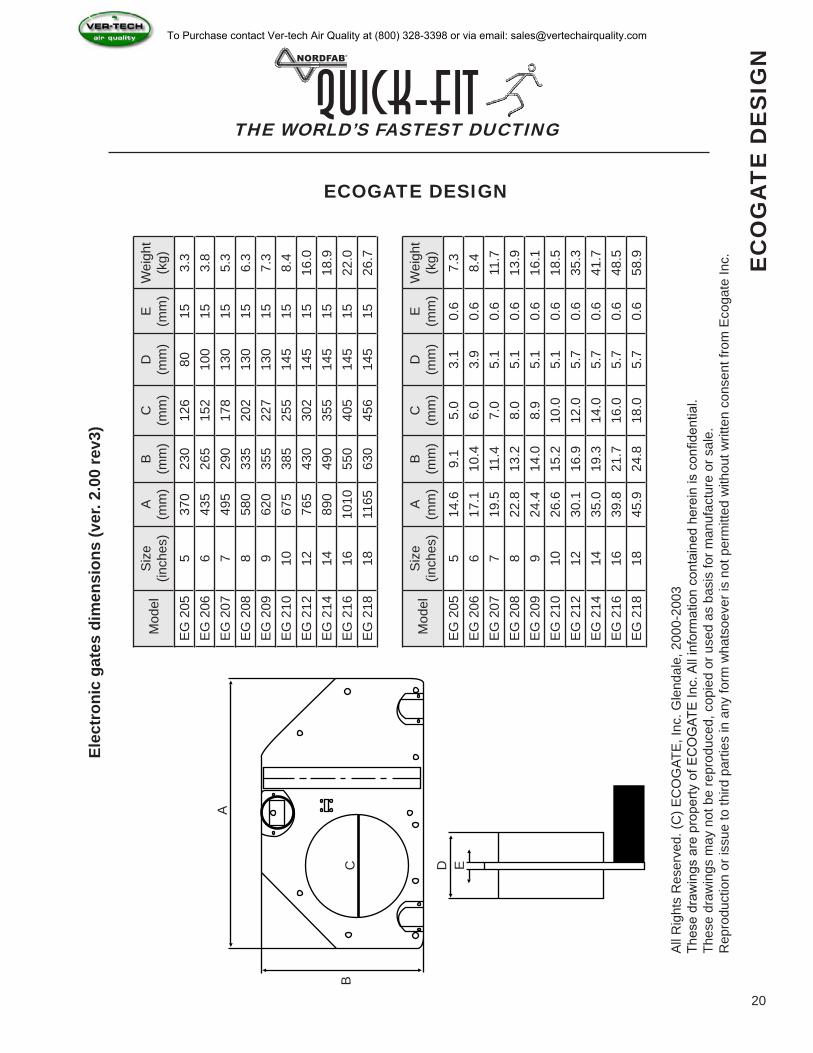
ECOGATE DESIGNA
BC D E
To Purchase contact Ver-tech Air Quality at (800) 328-3398 or via email: [email protected]
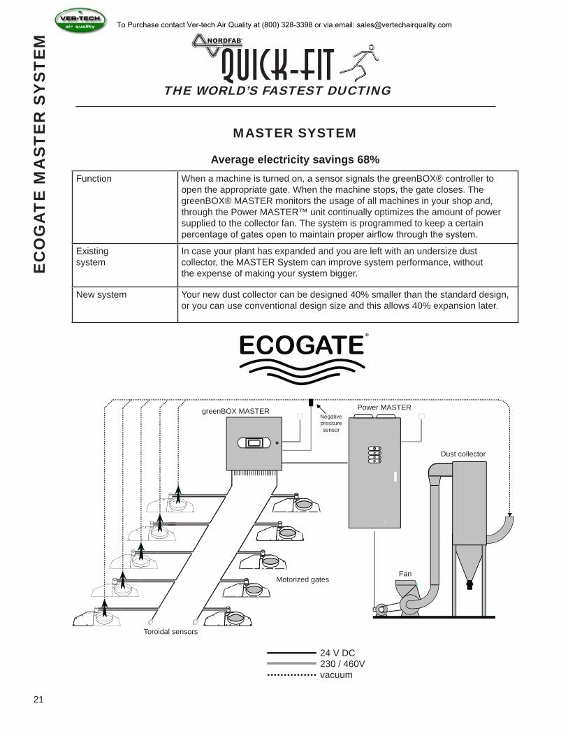
Function When a machine is turned on, a sensor signals the greenBOX® controller to open the appropriate gate. When the machine stops, the gate closes. The greenBOX® MASTER monitors the usage of all machines in your shop and, through the Power MASTER™ unit continually optimizes the amount of power supplied to the collector fan. The system is programmed to keep a certain percentage of gates open to maintain proper airflow through the system.
Existing system
In case your plant has expanded and you are left with an undersize dust collector, the MASTER System can improve system performance, without the expense of making your system bigger.
New system Your new dust collector can be designed 40% smaller than the standard design, or you can use conventional design size and this allows 40% expansion later.
THE WORLD’S FASTEST DUCTINGQuick-Fit
21
greenBOX MASTER Power MASTERNegative pressuresensor
Dust collector
FanMotorized gates
Toroidal sensors
24 V DC230 / 460Vvacuum
MASTER SYSTEM
Average electricity savings 68%
EC
OG
AT
E M
AS
TE
R S
YS
TE
MTo Purchase contact Ver-tech Air Quality at (800) 328-3398 or via email: [email protected]
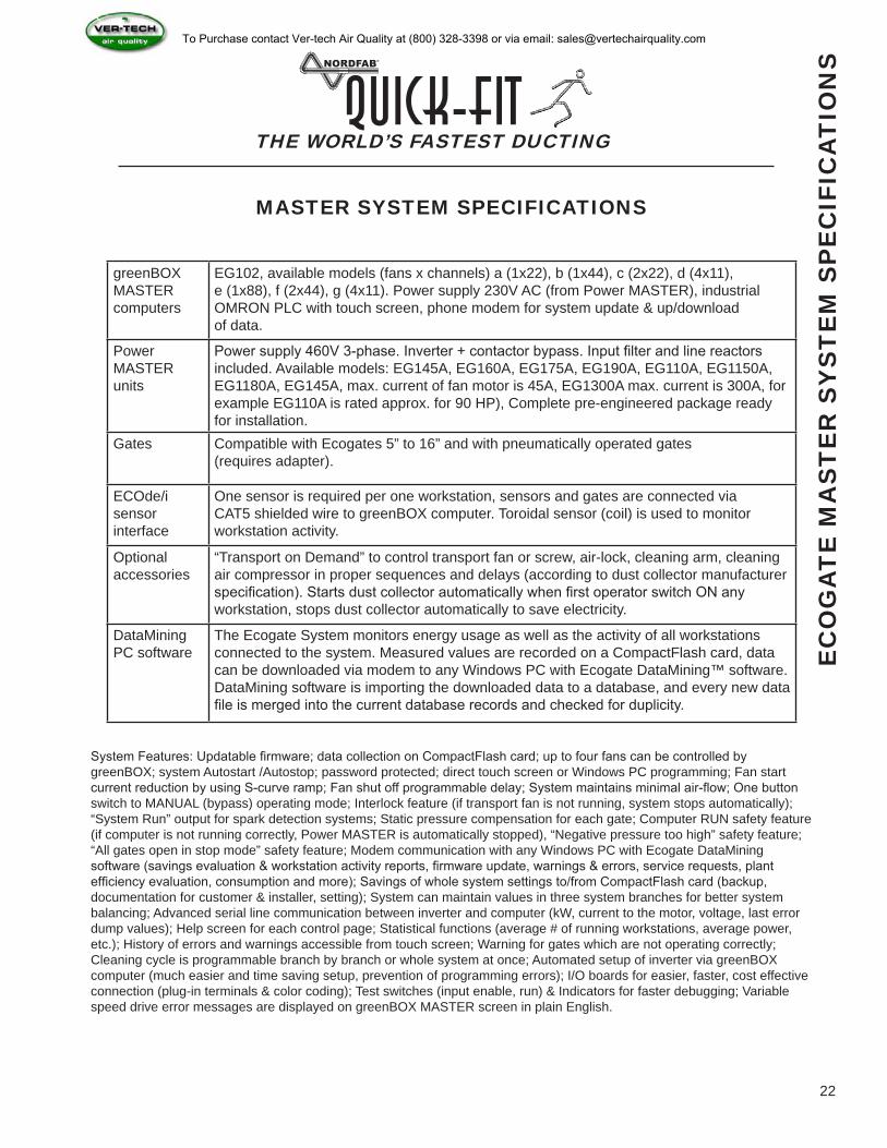
greenBOX MASTER computers
EG102, available models (fans x channels) a (1x22), b (1x44), c (2x22), d (4x11), e (1x88), f (2x44), g (4x11). Power supply 230V AC (from Power MASTER), industrial OMRON PLC with touch screen, phone modem for system update & up/download of data.
Power MASTER units
Power supply 460V 3-phase. Inverter + contactor bypass. Input filter and line reactors included. Available models: EG145A, EG160A, EG175A, EG190A, EG110A, EG1150A, EG1180A, EG145A, max. current of fan motor is 45A, EG1300A max. current is 300A, for example EG110A is rated approx. for 90 HP), Complete pre-engineered package ready for installation.
Gates Compatible with Ecogates 5” to 16” and with pneumatically operated gates (requires adapter).
ECOde/i sensor interface
One sensor is required per one workstation, sensors and gates are connected via CAT5 shielded wire to greenBOX computer. Toroidal sensor (coil) is used to monitor workstation activity.
Optional accessories
“Transport on Demand” to control transport fan or screw, air-lock, cleaning arm, cleaning air compressor in proper sequences and delays (according to dust collector manufacturer specification). Starts dust collector automatically when first operator switch ON any workstation, stops dust collector automatically to save electricity.
DataMining PC software
The Ecogate System monitors energy usage as well as the activity of all workstations connected to the system. Measured values are recorded on a CompactFlash card, data can be downloaded via modem to any Windows PC with Ecogate DataMining™ software. DataMining software is importing the downloaded data to a database, and every new data file is merged into the current database records and checked for duplicity.
THE WORLD’S FASTEST DUCTINGQuick-Fit
22
EC
OG
AT
E M
AS
TE
R S
YS
TE
M S
PE
CIF
ICA
TIO
NS
System Features: Updatable firmware; data collection on CompactFlash card; up to four fans can be controlled by greenBOX; system Autostart /Autostop; password protected; direct touch screen or Windows PC programming; Fan start current reduction by using S-curve ramp; Fan shut off programmable delay; System maintains minimal air-flow; One button switch to MANUAL (bypass) operating mode; Interlock feature (if transport fan is not running, system stops automatically); “System Run” output for spark detection systems; Static pressure compensation for each gate; Computer RUN safety feature (if computer is not running correctly, Power MASTER is automatically stopped), “Negative pressure too high” safety feature; “All gates open in stop mode” safety feature; Modem communication with any Windows PC with Ecogate DataMining software (savings evaluation & workstation activity reports, firmware update, warnings & errors, service requests, plant efficiency evaluation, consumption and more); Savings of whole system settings to/from CompactFlash card (backup, documentation for customer & installer, setting); System can maintain values in three system branches for better system balancing; Advanced serial line communication between inverter and computer (kW, current to the motor, voltage, last error dump values); Help screen for each control page; Statistical functions (average # of running workstations, average power, etc.); History of errors and warnings accessible from touch screen; Warning for gates which are not operating correctly; Cleaning cycle is programmable branch by branch or whole system at once; Automated setup of inverter via greenBOX computer (much easier and time saving setup, prevention of programming errors); I/O boards for easier, faster, cost effective connection (plug-in terminals & color coding); Test switches (input enable, run) & Indicators for faster debugging; Variable speed drive error messages are displayed on greenBOX MASTER screen in plain English.
MASTER SYSTEM SPECIFICATIONS
To Purchase contact Ver-tech Air Quality at (800) 328-3398 or via email: [email protected]
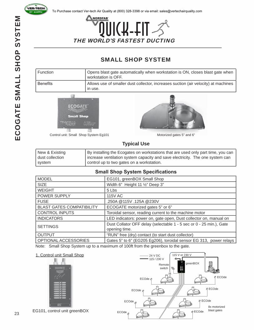
Function Opens blast gate automatically when workstation is ON, closes blast gate when workstation is OFF.
Benefits Allows use of smaller dust collector, increases suction (air velocity) at machines in use.
New & Existingdust collectionsystem
By installing the Ecogates on workstations that are used only part time, you can increase ventilation system capacity and save electricity. The one system can control up to two gates on a workstation.
MODEL EG101, greenBOX Small ShopSIZE Width 6” Height 11 ½” Deep 3”WEIGHT 5 LbsPOWER SUPPLY 115V ACFUSE .250A @115V .125A @230VBLAST GATES COMPATIBILITY ECOGATE motorized gates 5” or 6”CONTROL INPUTS Toroidal sensor, reading current to the machine motorINDICATORS LED indicators: power on, gate open, Dust collector on, manual on
SETTINGS Dust Collator OFF delay (selectable 1 - 5 sec or 0 - 25 min.), Gate opening time.
OUTPUT “RUN” free (dry) contact (to start dust collector)OPTIONAL ACCESSORIES Gates 5” to 6” (EG205 Eg206), toroidal sensor EG 313, power relays
12
3
45
6
7
8
greenBOX
ECOGATE
AUT O/ MANUALMOD
E
POWERONDU
ST COL LECT ORON
MANUAL ON
THE WORLD’S FASTEST DUCTINGQuick-Fit
23
SMALL SHOP SYSTEM
Typical Use
Small Shop System Specifications
Control unit: Small Shop System Eg101 Motorized gates 5” and 6”
Note: Small Shop System up to a maximum of 100ft from the greenbox to the gate.
1. Control unit Small Shop
EG101, control unit greenBOX
24 V DC115 / 230 V
115 V or 230 V
greenBOXRemoteswitch
ECOde
ECOde
ECOde
ECOde
ECOde
ECOde
ECOde
ECOde8x motorizedblast gates
EC
OG
AT
E S
MA
LL S
HO
P S
YS
TE
MTo Purchase contact Ver-tech Air Quality at (800) 328-3398 or via email: [email protected]
THE WORLD’S FASTEST DUCTINGQuick-Fit
24
EC
OG
AT
E F
AN
CU
RV
EE
CO
GA
TE
CFM
CLA
SS
ICA
L &
RE
GU
LAT
ED
DE
SIG
N
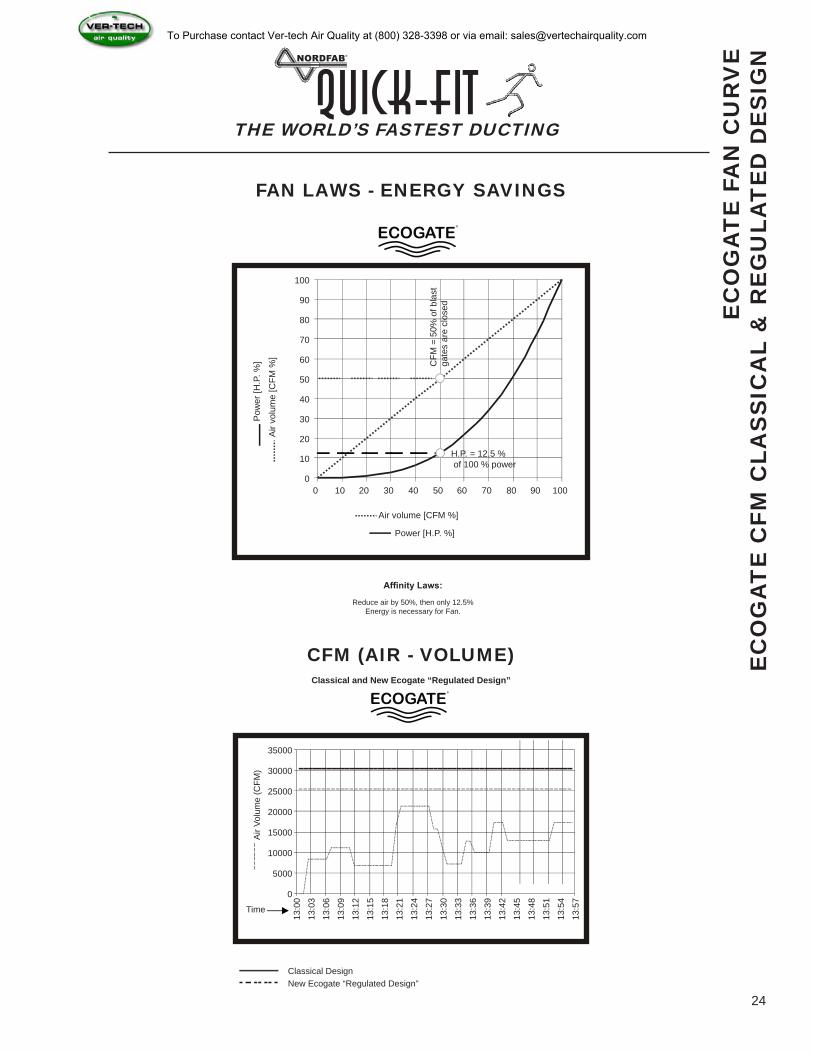
FAN LAWS - ENERGY SAVINGS
Affinity Laws:
Reduce air by 50%, then only 12.5% Energy is necessary for Fan.
Air volume [CFM %]
Power [H.P. %]
Air
volu
me
[CFM
%]
Pow
er [H
.P. %
]
100
90
80
70
60
50
40
30
20
10
00 10 20 30 40 50 60 70 80 90 100
H.P. = 12.5 % of 100 % power
CFM
= 5
0% o
f bla
st
gate
s ar
e cl
osed
35000
30000
25000
20000
15000
10000
5000
0
13:0
0
13:0
3
13:0
6
13:0
9
13:1
2
13:1
5
13:1
8
13:2
1
13:2
4
13:2
7
13:3
0
13:3
3
13:3
6
13:3
9
13:4
2
13:4
5
13:4
8
13:5
1
13:5
4
13:5
7
Time
Air
Volu
me
(CFM
)
Classical DesignNew Ecogate “Regulated Design”
CFM (AIR - VOLUME)Classical and New Ecogate “Regulated Design”
To Purchase contact Ver-tech Air Quality at (800) 328-3398 or via email: [email protected]
THE WORLD’S FASTEST DUCTINGQuick-Fit
25
18 Gauge
“A”
“B”
“C”
“D”
Air Flow
Automatic
NOTE: 6.9va Coil
80 psi
Closing Motion
Tubing
Opening Motion
115 Volt AC
Provided
115 Volt
Solenoid
Open
CloseSd25
BlkWG
BlkWG
TermBlock
1
2
3
4
5
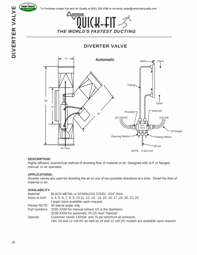
DESCRIPTION:Highly efficient, economical method of diverting flow of material or air. Designed with Q-F or flanged, manual, or air operated.
APPLICATIONS:Diverter valves are used for diverting the air to one of two possible directions at a time. Divert the flow of material or air.
AVAILABILITY:Material: BLACK METAL or STAINLESS STEEL 3/16” thickSizes in inch: 3, 4, 5, 6, 7, 8, 9, 10,11, 12, 13, 14, 15, 16, 17 ,18, 20, 22, 24 Larger sizes available upon request.Please NOTE: 45 lateral angle onlyPart numbers: 3235-XX00 for manual (where XX is the diameter) 3236-XX00 for automatic, PLUS read “Special”.Special: Customer needs 120Volt and 75 psi minimum air pressure. 240, 24 and 12 volt AC as well as 24 and 12 volt DC models are available upon request.
DIV
ER
TE
R V
ALV
E
DIVERTER VALVE
To Purchase contact Ver-tech Air Quality at (800) 328-3398 or via email: [email protected]
Quantity Dia. Of Pipe New Laser Weld Seam # of Sets
THE WORLD’S FASTEST DUCTINGQuick-Fit
26
FLA
SH
ING
(W
ALL
& R
OO
F)
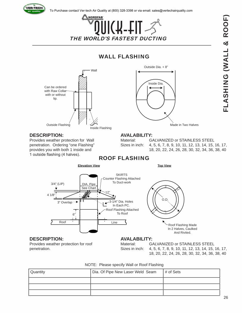
WALL FLASHING
Wall
Outside FlashingInside Flashing
Made in Two Halves
Outside Dia. + 8”
Inside Dia.
Elevation View
3/4” (LIP)
4 1/8”
3” Overlap
6”
Roof Line
Roof Flashing Attached To Roof
3-1/4” Dia. HolesIn Each PC.
12”
SKIRTSCounter Flashing Attached
To Duct-workDIA. PipeSee Chart
Top View
Roof Flashing MadeIn 2 Halves, Caulked
And Rivited.
O.D.
DESCRIPTION:Provides weather protection for Wall penetration. Ordering “one Flashing” provides you with both 1 inside and 1 outside flashing (4 halves).
AVALABILITY:Material: GALVANIZED or STAINLESS STEELSizes in inch: 4, 5, 6, 7, 8, 9, 10, 11, 12, 13, 14, 15, 16, 17, 18, 20, 22, 24, 26, 28, 30, 32, 34, 36, 38, 40
DESCRIPTION:Provides weather protection for roof penetration.
AVALABILITY:Material: GALVANIZED or STAINLESS STEELSizes in inch: 4, 5, 6, 7, 8, 9, 10, 11, 12, 13, 14, 15, 16, 17, 18, 20, 22, 24, 26, 28, 30, 32, 34, 36, 38, 40
NOTE: Please specify Wall or Roof Flashing
ROOF FLASHING
--------
--------
Can be ordered with Raw Collar with or without
lip.
To Purchase contact Ver-tech Air Quality at (800) 328-3398 or via email: [email protected]
QTY “A” “B” “C” “D1” “D” “E”
THE WORLD’S FASTEST DUCTINGQuick-Fit
27
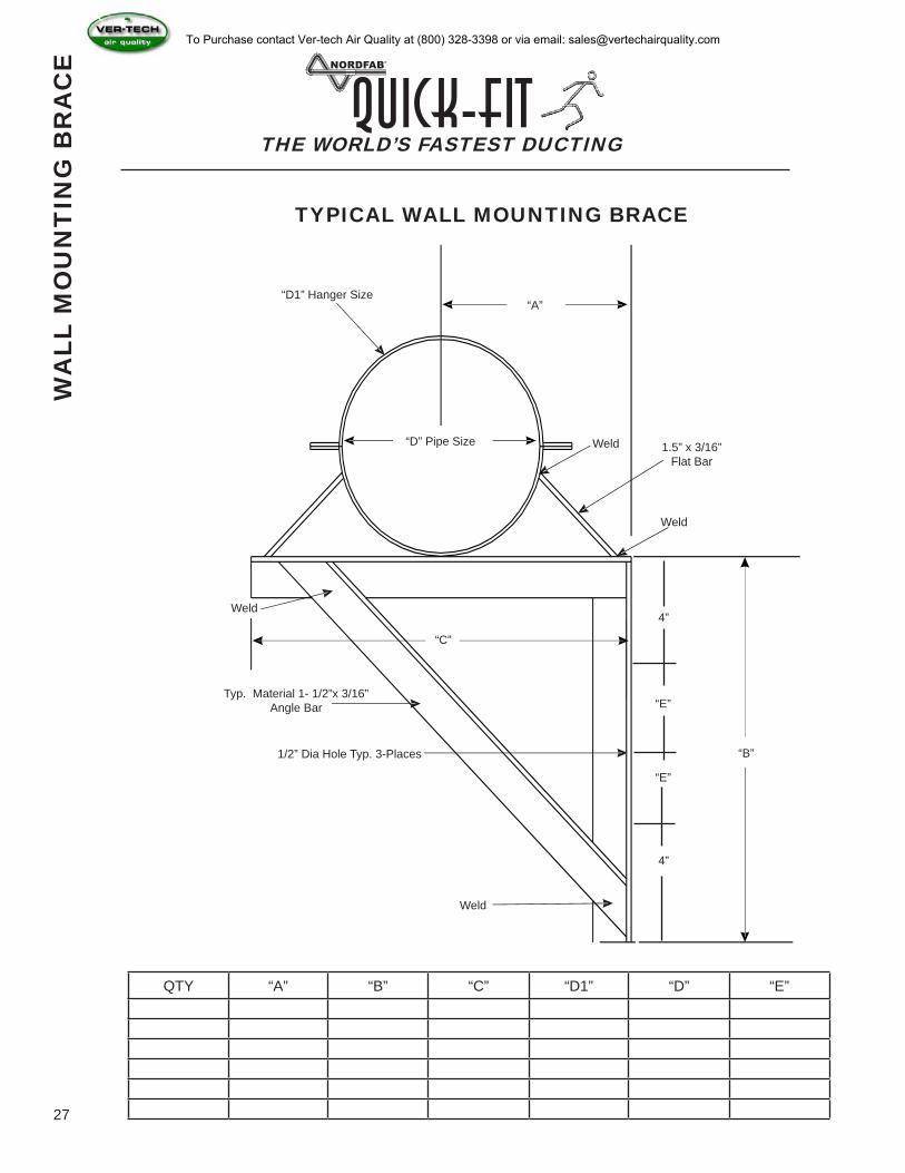
TYPICAL WALL MOUNTING BRACE
WA
LL M
OU
NT
ING
BR
AC
E
“D1” Hanger Size
“D” Pipe Size
“A”
Weld
Weld 1.5” x 3/16” Flat Bar
“C”
Weld
4”
“E”
“E”
4”
“B”
Typ. Material 1- 1/2”x 3/16”Angle Bar
1/2” Dia Hole Typ. 3-Places
Weld
To Purchase contact Ver-tech Air Quality at (800) 328-3398 or via email: [email protected]
THE WORLD’S FASTEST DUCTINGQuick-Fit
28
TY
PIC
AL
CE
ILIN
G H
AN
GIN
G M
ET
HO
D
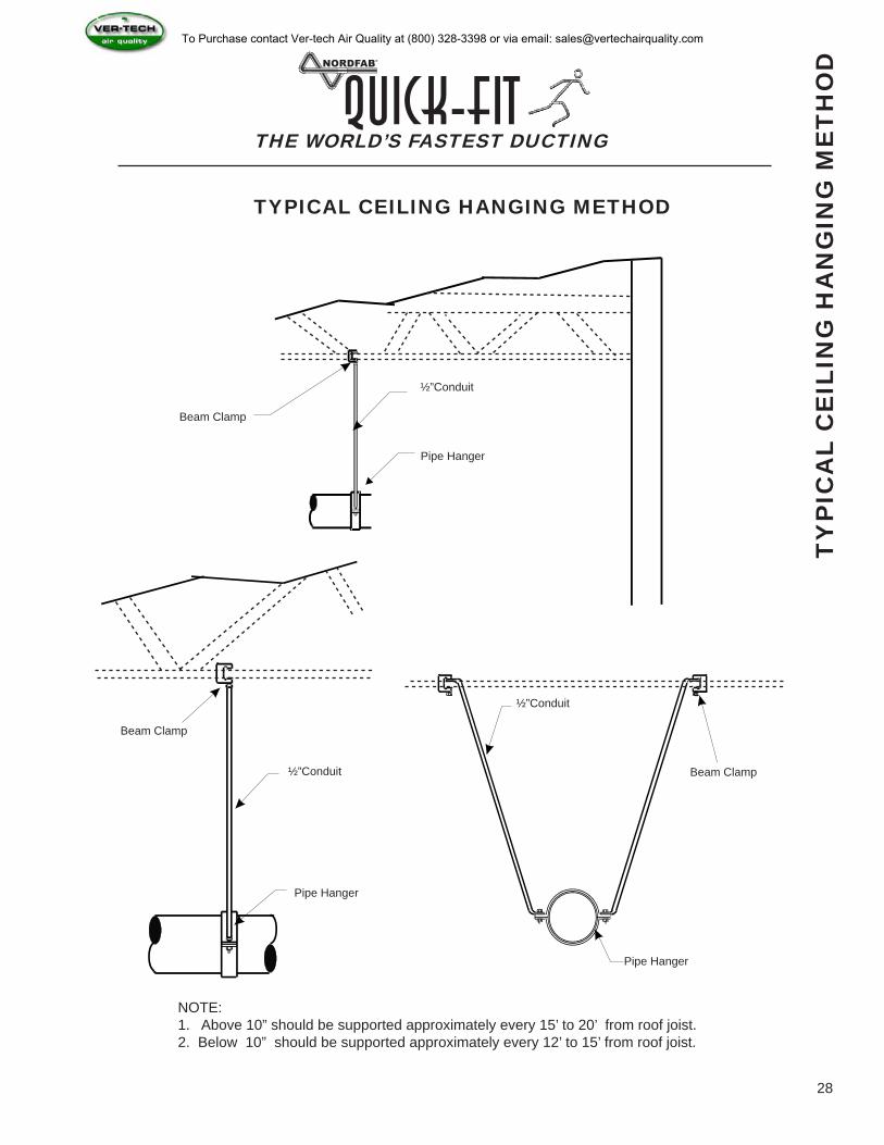
TYPICAL CEILING HANGING METHOD
Beam Clamp
½”Conduit
Pipe Hanger
Beam Clamp
½”Conduit
Pipe Hanger
½”Conduit
Pipe Hanger
Beam Clamp
NOTE:1. Above 10” should be supported approximately every 15’ to 20’ from roof joist.2. Below 10” should be supported approximately every 12’ to 15’ from roof joist.
To Purchase contact Ver-tech Air Quality at (800) 328-3398 or via email: [email protected]
THE WORLD’S FASTEST DUCTINGQuick-Fit
29
PIP
E S
TAN
D W
ITH
HA
NG
ER
BR
AC
KE
T
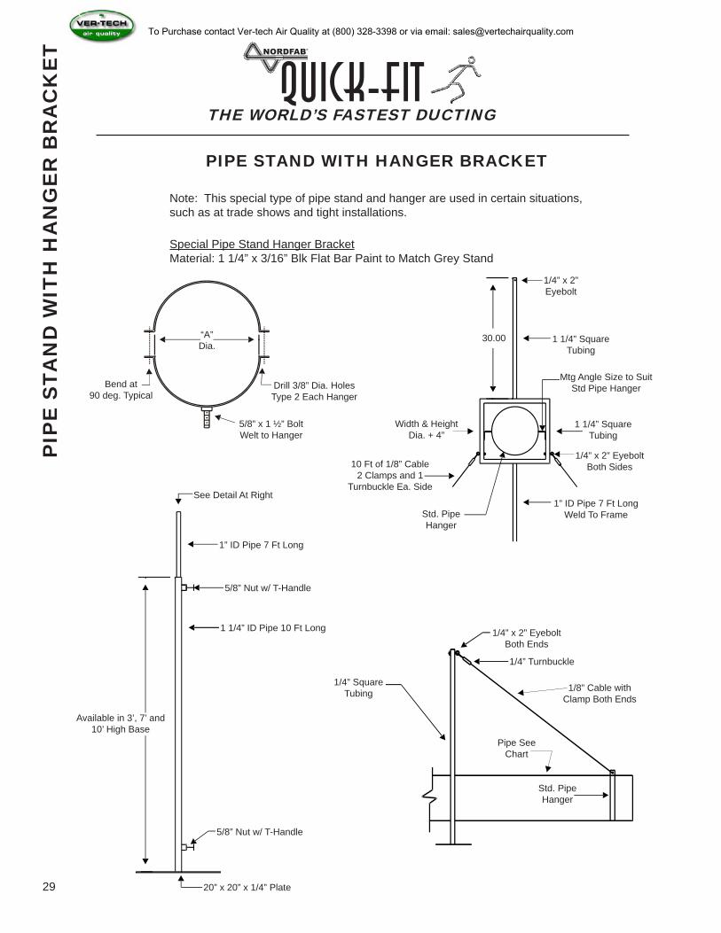
PIPE STAND WITH HANGER BRACKET
Note: This special type of pipe stand and hanger are used in certain situations, such as at trade shows and tight installations.
Special Pipe Stand Hanger BracketMaterial: 1 1/4” x 3/16” Blk Flat Bar Paint to Match Grey Stand
“A”Dia.
Bend at 90 deg. Typical
5/8” x 1 ½” BoltWelt to Hanger
Drill 3/8” Dia. HolesType 2 Each Hanger
10 Ft of 1/8” Cable2 Clamps and 1
Turnbuckle Ea. Side
Width & HeightDia. + 4”
30.00
1/4” x 2” Eyebolt
1 1/4” Square Tubing
Mtg Angle Size to SuitStd Pipe Hanger
1 1/4” SquareTubing
1/4” x 2” EyeboltBoth Sides
1” ID Pipe 7 Ft LongWeld To FrameStd. Pipe
Hanger
See Detail At Right
1” ID Pipe 7 Ft Long
5/8” Nut w/ T-Handle
1 1/4” ID Pipe 10 Ft Long
20” x 20” x 1/4” Plate
5/8” Nut w/ T-Handle
Available in 3’, 7’ and10’ High Base
1/4” SquareTubing
1/4” x 2” EyeboltBoth Ends
1/4” Turnbuckle
1/8” Cable withClamp Both Ends
Pipe SeeChart
Std. Pipe Hanger
To Purchase contact Ver-tech Air Quality at (800) 328-3398 or via email: [email protected]
Size Working Load Limit (WLL) at 5:1 safety factor
Standard Lengths (meters) Standard Length (feet)
No. 1 10 kg / 22lb 1, 1.5, 2, 2.5, 3, 4, 5 & 10 5, 10, 15, 30No. 2 35 kg / 77lb 1, 1.5, 2, 2.5, 3, 4, 5 & 10 15, 10, 15, 30No. 3 80 kg / 176lb 1, 2, 3, 4, 5, & 10 15, 10, 15, 30No. 4 225 kg / 495lb 1, 2, 3, 4, 5, & 10 15, 10, 15, 30No. 5 325 kg / 715 lb 1, 2, 3, 4, 5, & 10 15, 10, 15, 30
ITEM # LENGTH WEIGHT AVAILABILITY3266-1500-022LBS 15’ 22 LBS 5-7 DAYS3266-1500-100LBS 15’ 100 LBS 5-7 DAYS3266-1500-200LBS 15’ 200 LBS IN STOCK3266-1500-495LBS 15’ 495 LBS IN STOCK3266-1500-715LBS 15’ 715 LBS 5-7 DAYS
THE WORLD’S FASTEST DUCTINGQuick-Fit
30
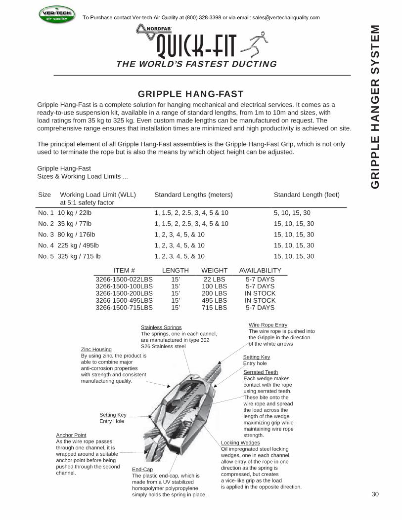
GRIPPLE HANG-FASTGripple Hang-Fast is a complete solution for hanging mechanical and electrical services. It comes as a ready-to-use suspension kit, available in a range of standard lengths, from 1m to 10m and sizes, with load ratings from 35 kg to 325 kg. Even custom made lengths can be manufactured on request. The comprehensive range ensures that installation times are minimized and high productivity is achieved on site.
The principal element of all Gripple Hang-Fast assemblies is the Gripple Hang-Fast Grip, which is not only used to terminate the rope but is also the means by which object height can be adjusted.
Gripple Hang-FastSizes & Working Load Limits ...
Zinc HousingBy using zinc, the product is able to combine majoranti-corrosion propertieswith strength and consistentmanufacturing quality.
Stainless SpringsThe springs, one in each cannel, are manufactured in type 302S26 Stainless steel
Wire Rope EntryThe wire rope is pushed intothe Gripple in the directionof the white arrows
Setting KeyEntry hole
Serrated TeethEach wedge makes contact with the rope using serrated teeth.These bite onto the wire rope and spread the load across the length of the wedge maximizing grip while maintaining wire rope strength.
Locking WedgesOil impregnated steel lockingwedges, one in each channel,allow entry of the rope in onedirection as the spring is compressed, but createsa vice-like grip as the load is applied in the opposite direction.
End-CapThe plastic end-cap, which ismade from a UV stabilizedhomopolymer polypropylenesimply holds the spring in place.
Anchor PointAs the wire rope passesthrough one channel, it iswrapped around a suitableanchor point before beingpushed through the secondchannel.
Setting KeyEntry Hole
GR
IPP
LE H
AN
GE
R S
YS
TE
M
To Purchase contact Ver-tech Air Quality at (800) 328-3398 or via email: [email protected]
THE WORLD’S FASTEST DUCTINGQuick-Fit
31
NO
-LO
SS
STA
CK
-HE
AD
IN
LIN
E S
ILE
NC
ER
Ø PART NO. ENDS LENGTH(L)
GAUGE HOUSING
WEIGHT (GALV)
3” 3106-0300 QF 28” 16 10.00 4” 3106-0400 QF 28” 16 21.00 5” 3106-0500 QF 28” 16 35.00 6” 3106-0600 QF 30” 16 43.00 7” 3106-0700 QF 30” 16 54.00 8” 3106-0800 QF 35” 16 65.00 9” 3106-0900 QF 40” 16 76.00
10” 3106-1000 QF 48” 16 89.00 12” 3106-1200 QF 54” 16 104.00 14” 3106-1400 QF 60” 16 122.00 16” 3106-1600 QF 64” 16 176.00 18” 3106-1800 QF 68” 16 225.00 20” 3106-2000 QF 72” 16 265.00 22” 3106-2200 QF 76” 16 310.00 24” 3106-2400 QF 78” 16 406.00 26” 3106-2600 FLANGE 78” 16 546.00 28” 3106-2800 FLANGE 78” 16 600.00 30” 3106-3000 FLANGE 78” 16 678.00 32” 3106-3200 FLANGE 78” 16 700.00 34” 3106-3400 FLANGE 78” 16 770.00 36” 3106-3600 FLANGE 78” 16 897.00 38” 3106-3800 FLANGE 78” 16 974.00 40” 3106-4000 FLANGE 78” 16 1,118.00
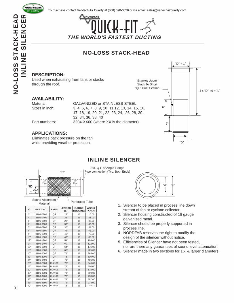
NO-LOSS STACK-HEAD
Bracket UpperStack To Short
“QF” Duct Section4 x “D” +6 = “L”
“D” + 1”
6”
6”
“D”
Sound Absorbent Material Perforated Tube
Std. Q-F or Angle FlangePipe connection (Typ. Both Ends)“C”
“B”“A”A/2
Air Flow
Air Flow
“B”“A”
DESCRIPTION:Used when exhausting from fans or stacks through the roof.
APPLICATIONS:Eliminates back pressure on the fan while providing weather protection.
AVAILABILITY:Material: GALVANIZED or STAINLESS STEELSizes in inch: 3, 4, 5, 6, 7, 8, 9, 10, 11,12, 13, 14, 15, 16, 17, 18, 19, 20, 21, 22, 23, 24, 26, 28, 30, 32, 34, 36, 38, 40Part numbers: 3204-XX00 (where XX is the diameter)
INLINE SILENCER
1. Silencer to be placed in process line down stream of fan or cyclone collector.2. Silencer housing constructed of 16 gauge galvanized metal.3. Silencer should be properly supported in process line.4. NORDFAB reserves the right to modify the design of the silencer without notice.5. Efficiencies of Silencer have not been tested, nor are there any guarantees of sound level attenuation.6. Silencer made in two sections for 16” & larger diameters.
To Purchase contact Ver-tech Air Quality at (800) 328-3398 or via email: [email protected]
THE WORLD’S FASTEST DUCTINGQuick-Fit
32
L
AB
OR
GU
IDE
LIN
ES
T
HIN
GS
TO
BE
AW
AR
E O
F
RULE OF THUMB LABOR GUIDELINESA) Long straight runs and trunk-lines • “Q-F” duct = 6 to 10 man hours per 100’ • Flanged duct = 20 man hours per 100’
B) Machine Connections • Machine with 1 or 2 ports = 1.5 to 3 man hours per port. • Machines with 3 or more ports = 4 man hours per port.
A+B = TOTAL MAN HOURSOR
QUICK METHOD
(TOTAL # OF PORTS) x 3 HOURS EACH = “X”“X” x 2 = DUCTING SYSTEM TOTAL MAN HOURS
NOTE: The above methods should be used for comparison and budgetary purposes only!! By no means should they be used to confirm a job installation. It should be the sales person’s responsibility to analyze each individual job and make his/her own judgement.
THINGS TO BE AWARE OF WHEN ORDERING “Q-F”1. Order one clamp per “Q-F” component. • 1 - duct = 1 clamp • 2 - elbows = 2 clamps
2. Specify dimensional information to speed up process: • Transitions A,B,D,L,X, Y and flange style • Branches A x B x C, or A x B x D, or A x B x C x D • Tap-In or In-cuts A, B • Reducer All diameters and end style
THERE IS NO SUCH THING AS TOO MUCH INFORMATION !
3. Look for 60 degree elbows to compliment branch orders. This is typical application since the two components will create a perpendicular run to the trunk line.
4. Ask for flange styles, hole patterns, ID, OD, when applicable. Typical components requiring flanges will be parts that connect to filters, fans or other types of equipment.
To Purchase contact Ver-tech Air Quality at (800) 328-3398 or via email: [email protected]
THE WORLD’S FASTEST DUCTINGQuick-Fit
33
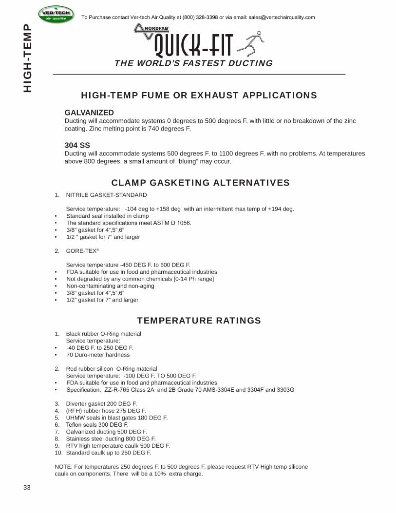
HIGH-TEMP FUME OR EXHAUST APPLICATIONS
GALVANIZEDDucting will accommodate systems 0 degrees to 500 degrees F. with little or no breakdown of the zinc coating. Zinc melting point is 740 degrees F.
304 SSDucting will accommodate systems 500 degrees F. to 1100 degrees F. with no problems. At temperatures above 800 degrees, a small amount of “bluing” may occur.
CLAMP GASKETING ALTERNATIVES1. NITRILE GASKET-STANDARD
Service temperature: -104 deg to +158 deg with an intermittent max temp of +194 deg.• Standard seal installed in clamp• The standard specifications meet ASTM D 1056.• 3/8” gasket for 4”,5”,6”• 1/2 ” gasket for 7” and larger
2. GORE-TEX®
Service temperature -450 DEG F. to 600 DEG F.• FDA suitable for use in food and pharmaceutical industries• Not degraded by any common chemicals [0-14 Ph range]• Non-contaminating and non-aging• 3/8” gasket for 4”,5”,6”• 1/2” gasket for 7” and larger
TEMPERATURE RATINGS1. Black rubber O-Ring material Service temperature:• -40 DEG F. to 250 DEG F.• 70 Duro-meter hardness
2. Red rubber silicon O-Ring material Service temperature: -100 DEG F. TO 500 DEG F.• FDA suitable for use in food and pharmaceutical industries• Specification: ZZ-R-765 Class 2A and 2B Grade 70 AMS-3304E and 3304F and 3303G
3. Diverter gasket 200 DEG F.4. (RFH) rubber hose 275 DEG F.5. UHMW seals in blast gates 180 DEG F.6. Teflon seals 300 DEG F.7. Galvanized ducting 500 DEG F.8. Stainless steel ducting 800 DEG F.9. RTV high temperature caulk 500 DEG F.10. Standard caulk up to 250 DEG F.
NOTE: For temperatures 250 degrees F. to 500 degrees F. please request RTV High temp silicone caulk on components. There will be a 10% extra charge.
HIG
H-T
EM
PTo Purchase contact Ver-tech Air Quality at (800) 328-3398 or via email: [email protected]
THE WORLD’S FASTEST DUCTINGQuick-Fit
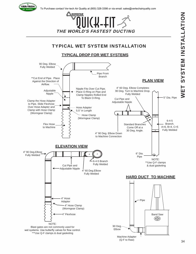
Band Saw
90 Deg. ElbowFully Welded
**Cut End of Pipe. Place Against the Direction of
Airflow.
AdjustableNipple
Clamp the Hose Adapterto Pipe. Slide FlexhoseOver Hose Adapter andClamp with Hose Clamp
(Wormgear Clamp)
Flex Hoseto Machine
Hose Clamp(Wormgear Clamp)
Hose Adapter5.5” in Length
Nipple Fits Over Cut Pipe.Place O-Ring on Pipe and Clamp Nipples Rolled End
To Black O-Ring.
Pipe From Branch
WE
T S
YS
TE
M I
NS
TALL
AT
ION
4” 60 Deg. Elbow Completes90 Deg. Turn to Machine Drop.
Fully Welded
Cut Pipe andAdjustable Nipple
Standard BranchesCome Off at a 30 Deg. Angle.
4” 90 Deg. Elbow Downto Machine Connection
5” Dia. Pipe
6-4-5Branch.
A=6, B=4, C=5Fully Welded
6” Dia. Pipe
NOTE:**Use Q-F clamps & dual gasketing
A
B C
AB4” 90 Deg.Elbow
Fully Welded
Cut Pipe andAdjustable Nipple
4” 60 Deg.ElbowFully Welded
6-4-5 BranchFully Welded
4” HoseAdapter
4” Hose Clamp(Wormgear Clamp)
4” Flexhose
NOTE:Blast gates are not commonly used for
wet systems. Use butterfly valves for flow control. ***Use Q-F clamps & dual gasketing
90 Deg.Elbow
Machine Adapter(Q-F to Raw)
Pipe
TYPICAL DROP FOR WET SYSTEMS
PLAN VIEW
ELEVATION VIEW
HARD DUCT TO MACHINE
TYPICAL WET SYSTEM INSTALLATION
34
To Purchase contact Ver-tech Air Quality at (800) 328-3398 or via email: [email protected]
THE WORLD’S FASTEST DUCTINGQuick-Fit
35
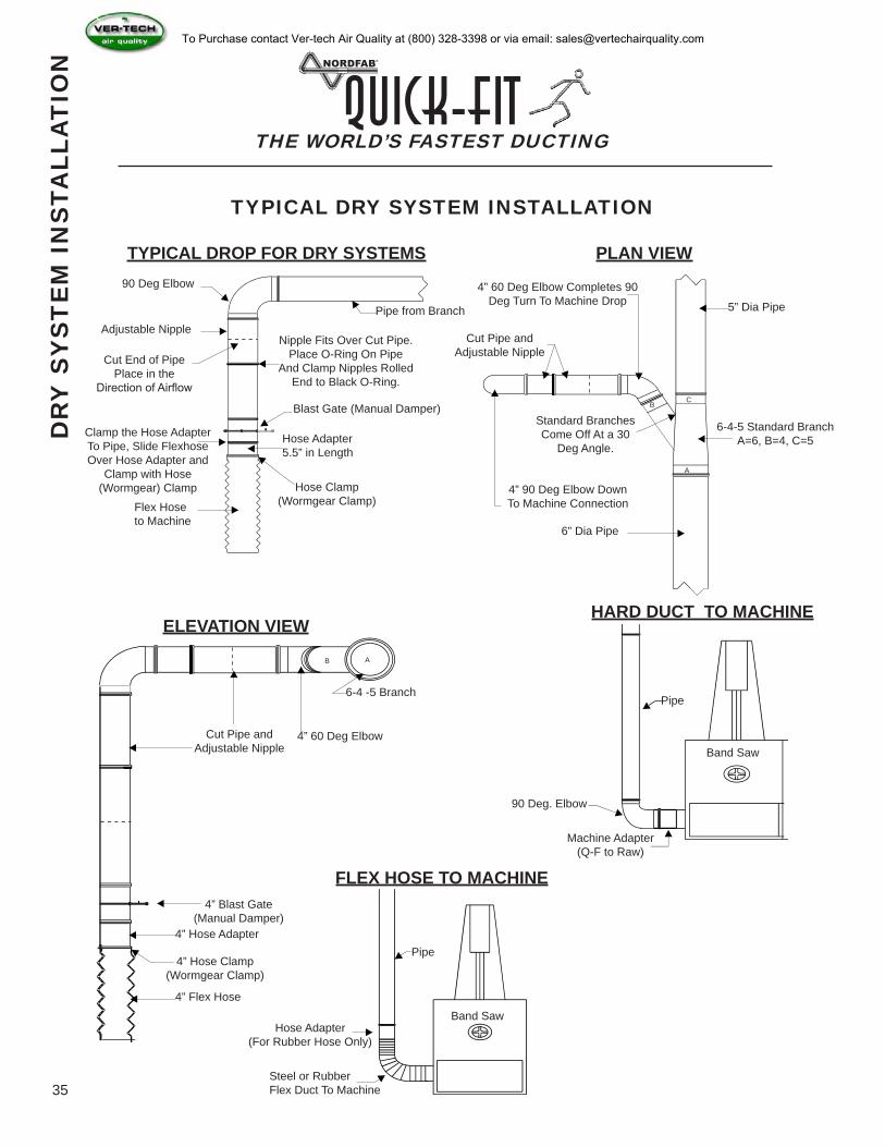
90 Deg Elbow
Adjustable Nipple
Cut End of Pipe Place in the
Direction of Airflow
Clamp the Hose Adapter To Pipe, Slide Flexhose Over Hose Adapter and
Clamp with Hose (Wormgear) Clamp
Flex Hose to Machine
Pipe from Branch
Nipple Fits Over Cut Pipe. Place O-Ring On Pipe
And Clamp Nipples Rolled End to Black O-Ring.
Blast Gate (Manual Damper)
Hose Clamp (Wormgear Clamp)
Hose Adapter 5.5” in Length
Cut Pipe and Adjustable Nipple
4” 60 Deg Elbow Completes 90 Deg Turn To Machine Drop 5” Dia Pipe
6-4-5 Standard Branch A=6, B=4, C=5
6” Dia Pipe
4” 90 Deg Elbow Down To Machine Connection
Standard Branches Come Off At a 30
Deg Angle.
Cut Pipe and Adjustable Nipple
4” 60 Deg Elbow
6-4 -5 Branch
4” Blast Gate(Manual Damper)
4” Hose Adapter
4” Hose Clamp(Wormgear Clamp)
4” Flex Hose
Machine Adapter(Q-F to Raw)
90 Deg. Elbow
Pipe
Band Saw
A
BC
AB
Band SawHose Adapter
(For Rubber Hose Only)
Steel or RubberFlex Duct To Machine
Pipe
DR
Y S
YS
TE
M I
NS
TALL
AT
ION
TYPICAL DROP FOR DRY SYSTEMS PLAN VIEW
ELEVATION VIEWHARD DUCT TO MACHINE
FLEX HOSE TO MACHINE
TYPICAL DRY SYSTEM INSTALLATION
To Purchase contact Ver-tech Air Quality at (800) 328-3398 or via email: [email protected]
THE WORLD’S FASTEST DUCTINGQuick-Fit
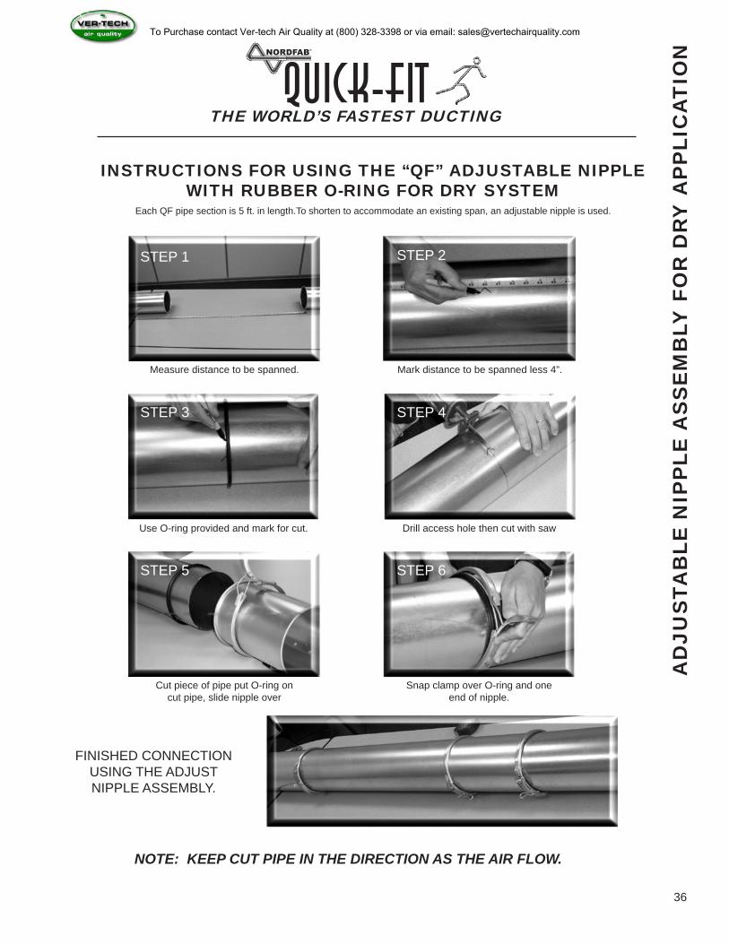
INSTRUCTIONS FOR USING THE “QF” ADJUSTABLE NIPPLE WITH RUBBER O-RING FOR DRY SYSTEM
Each QF pipe section is 5 ft. in length.To shorten to accommodate an existing span, an adjustable nipple is used.
Measure distance to be spanned.
Use O-ring provided and mark for cut.
Cut piece of pipe put O-ring on cut pipe, slide nipple over
Mark distance to be spanned less 4”.
Drill access hole then cut with saw
Snap clamp over O-ring and one end of nipple.
FINISHED CONNECTION USING THE ADJUSTNIPPLE ASSEMBLY.
NOTE: KEEP CUT PIPE IN THE DIRECTION AS THE AIR FLOW.
STEP 1 STEP 2
STEP 4
STEP 6
STEP 3
STEP 5
AD
JUS
TAB
LE N
IPP
LE A
SS
EM
BLY
FO
R D
RY
AP
PLI
CA
TIO
N
36
To Purchase contact Ver-tech Air Quality at (800) 328-3398 or via email: [email protected]
THE WORLD’S FASTEST DUCTINGQuick-Fit
37
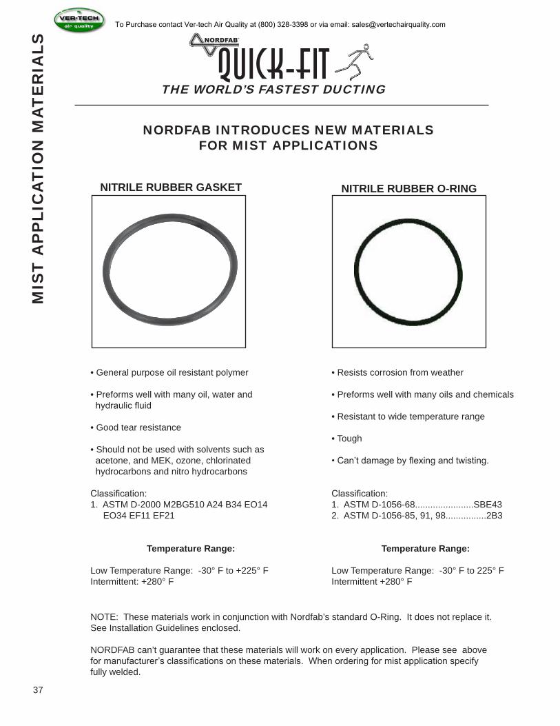
NORDFAB INTRODUCES NEW MATERIALS FOR MIST APPLICATIONS
NITRILE RUBBER GASKET NITRILE RUBBER O-RING
MIS
T A
PP
LIC
AT
ION
MA
TE
RIA
LS
• General purpose oil resistant polymer
• Preforms well with many oil, water and hydraulic fluid
• Good tear resistance
• Should not be used with solvents such as acetone, and MEK, ozone, chlorinated hydrocarbons and nitro hydrocarbons
Classification:1. ASTM D-2000 M2BG510 A24 B34 EO14 EO34 EF11 EF21
Temperature Range:
Low Temperature Range: -30° F to +225° F Intermittent: +280° F
• Resists corrosion from weather
• Preforms well with many oils and chemicals
• Resistant to wide temperature range
• Tough
• Can’t damage by flexing and twisting.
Classification:1. ASTM D-1056-68.......................SBE432. ASTM D-1056-85, 91, 98................2B3
Temperature Range:
Low Temperature Range: -30° F to 225° F Intermittent +280° F
NOTE: These materials work in conjunction with Nordfab’s standard O-Ring. It does not replace it. See Installation Guidelines enclosed.
NORDFAB can’t guarantee that these materials will work on every application. Please see above for manufacturer’s classifications on these materials. When ordering for mist application specify fully welded.
To Purchase contact Ver-tech Air Quality at (800) 328-3398 or via email: [email protected]
THE WORLD’S FASTEST DUCTINGQuick-Fit
38
MIS
T O
R W
ET
AP
PLI
CA
TIO
N F
OR
PIP
E
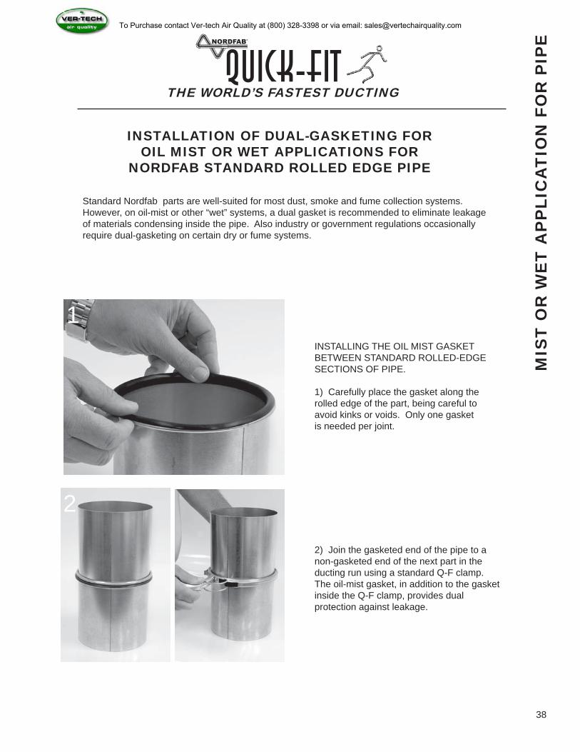
INSTALLATION OF DUAL-GASKETING FOR OIL MIST OR WET APPLICATIONS FOR
NORDFAB STANDARD ROLLED EDGE PIPE
Standard Nordfab parts are well-suited for most dust, smoke and fume collection systems. However, on oil-mist or other “wet” systems, a dual gasket is recommended to eliminate leakage of materials condensing inside the pipe. Also industry or government regulations occasionally require dual-gasketing on certain dry or fume systems.
INSTALLING THE OIL MIST GASKET BETWEEN STANDARD ROLLED-EDGE SECTIONS OF PIPE.
1) Carefully place the gasket along the rolled edge of the part, being careful to avoid kinks or voids. Only one gasket is needed per joint.
2) Join the gasketed end of the pipe to a non-gasketed end of the next part in the ducting run using a standard Q-F clamp. The oil-mist gasket, in addition to the gasket inside the Q-F clamp, provides dual protection against leakage.
1
2
To Purchase contact Ver-tech Air Quality at (800) 328-3398 or via email: [email protected]
THE WORLD’S FASTEST DUCTINGQuick-Fit
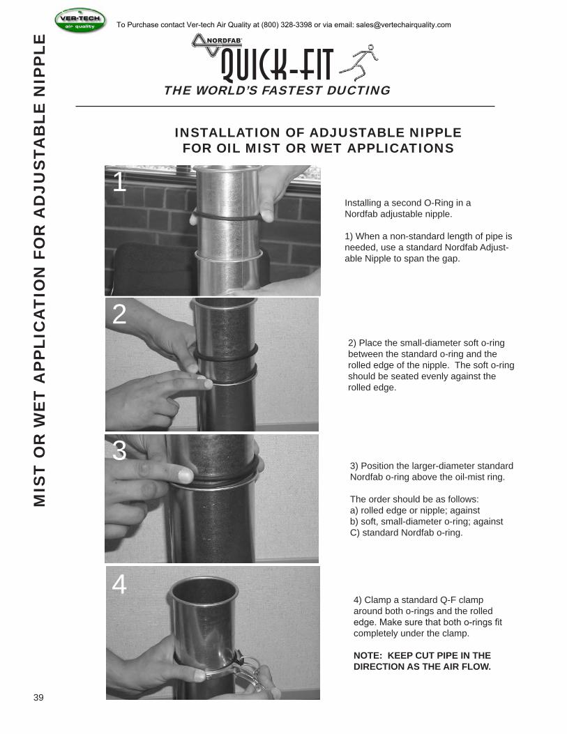
INSTALLATION OF ADJUSTABLE NIPPLE FOR OIL MIST OR WET APPLICATIONS
Installing a second O-Ring in a Nordfab adjustable nipple.
1) When a non-standard length of pipe is needed, use a standard Nordfab Adjust-able Nipple to span the gap.
2) Place the small-diameter soft o-ring between the standard o-ring and the rolled edge of the nipple. The soft o-ring should be seated evenly against the rolled edge.
3) Position the larger-diameter standard Nordfab o-ring above the oil-mist ring.
The order should be as follows:a) rolled edge or nipple; againstb) soft, small-diameter o-ring; againstC) standard Nordfab o-ring.
4) Clamp a standard Q-F clamp around both o-rings and the rolled edge. Make sure that both o-rings fit completely under the clamp.
NOTE: KEEP CUT PIPE IN THE DIRECTION AS THE AIR FLOW.
MIS
T O
R W
ET
AP
PLI
CA
TIO
N F
OR
AD
JUS
TAB
LE N
IPP
LE
1
2
3
4
39
To Purchase contact Ver-tech Air Quality at (800) 328-3398 or via email: [email protected]
THE WORLD’S FASTEST DUCTINGQuick-Fit
BR
AN
CH
ST
YLE
S
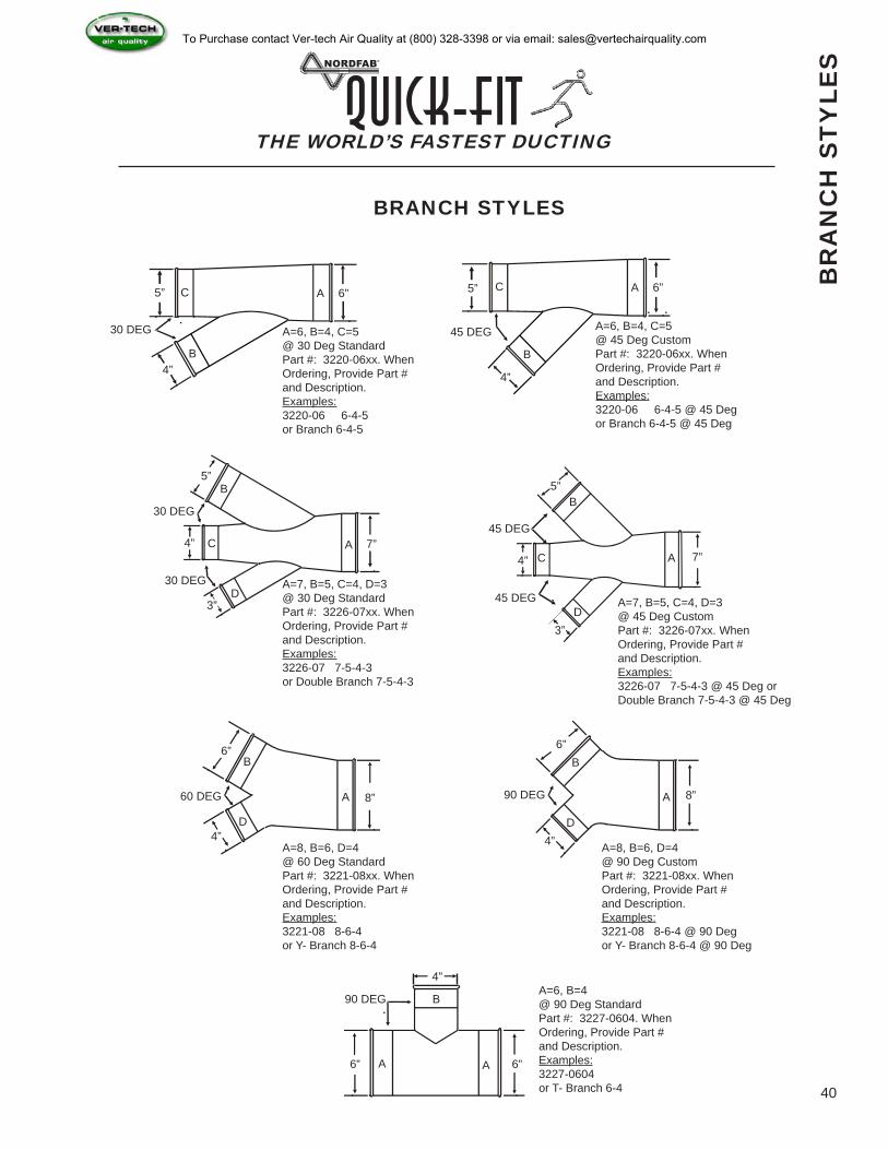
BRANCH STYLES
AC
B
5”
4”
6”
30 DEG A=6, B=4, C=5@ 30 Deg StandardPart #: 3220-06xx. WhenOrdering, Provide Part #and Description.Examples:3220-06 6-4-5or Branch 6-4-5
AC
B
5”
4”
6”
45 DEG A=6, B=4, C=5@ 45 Deg CustomPart #: 3220-06xx. When Ordering, Provide Part #and Description.Examples:3220-06 6-4-5 @ 45 Degor Branch 6-4-5 @ 45 Deg
AC
B5”
4” 7”
30 DEG A=7, B=5, C=4, D=3@ 30 Deg StandardPart #: 3226-07xx. When Ordering, Provide Part #and Description.Examples:3226-07 7-5-4-3or Double Branch 7-5-4-3
D
30 DEG
3”
AC
B5”
4” 7”
45 DEG A=7, B=5, C=4, D=3@ 45 Deg CustomPart #: 3226-07xx. When Ordering, Provide Part #and Description.Examples:3226-07 7-5-4-3 @ 45 Deg or Double Branch 7-5-4-3 @ 45 Deg
D
45 DEG
3”
A
B6”
4”
8”60 DEG
A=8, B=6, D=4@ 60 Deg StandardPart #: 3221-08xx. When Ordering, Provide Part #and Description.Examples:3221-08 8-6-4or Y- Branch 8-6-4
D
A
B6”
4”
8”90 DEG
A=8, B=6, D=4@ 90 Deg CustomPart #: 3221-08xx. When Ordering, Provide Part #and Description.Examples:3221-08 8-6-4 @ 90 Degor Y- Branch 8-6-4 @ 90 Deg
D
A
B
6”
4”
6”
90 DEGA=6, B=4@ 90 Deg StandardPart #: 3227-0604. When Ordering, Provide Part #and Description.Examples:3227-0604 or T- Branch 6-4
A
40
To Purchase contact Ver-tech Air Quality at (800) 328-3398 or via email: [email protected]
Item # Qty. “D” “A” “B” “X”
Std 2”“Y”
Std 2” “L” Gauge FlangeMaterial
FlgDwg Special Notes
THE WORLD’S FASTEST DUCTINGQuick-Fit
TR
AN
SIT
ION
ST
YLE
S
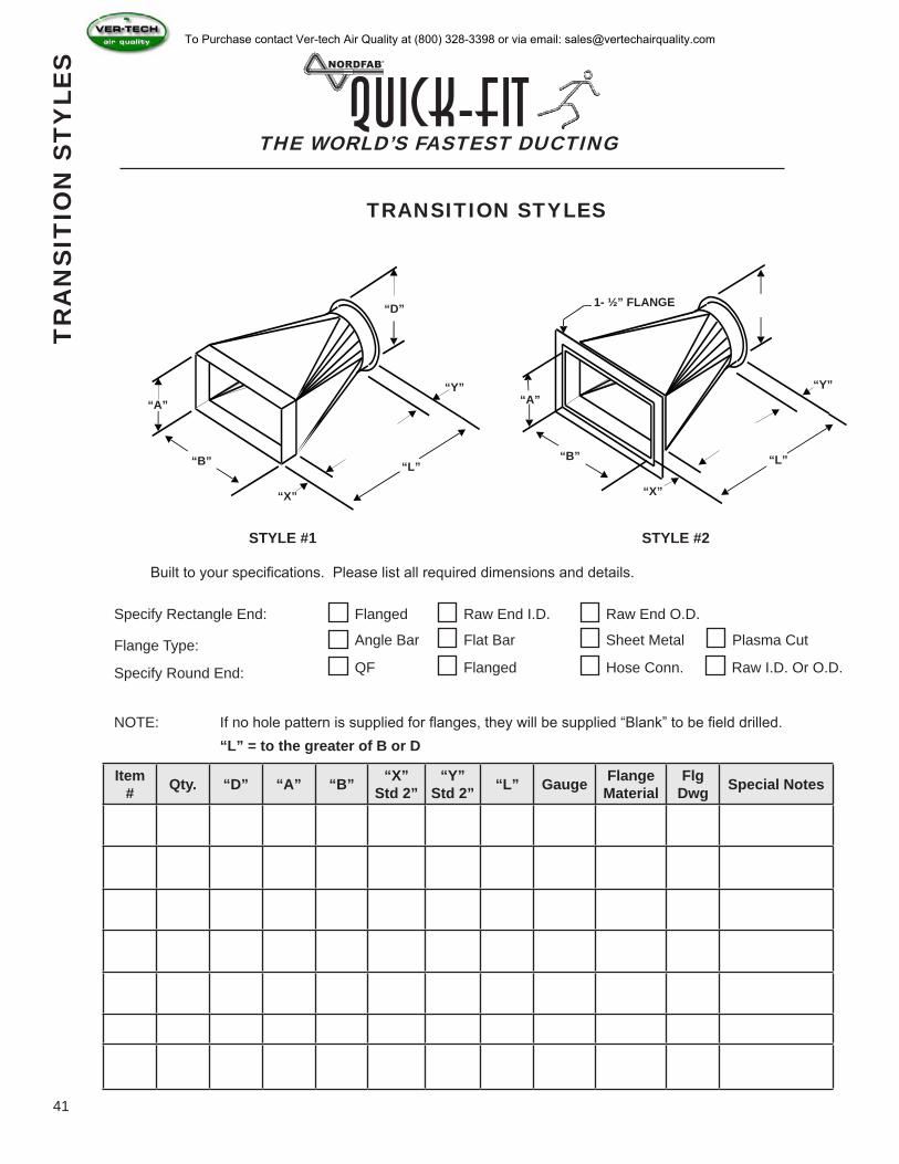
TRANSITION STYLES
“A”
“B”
“X”
“L”
“Y”
“D”
“A”
“B”
“X”
“L”
“Y”
1- ½” FLANGE
STYLE #1 STYLE #2
Built to your specifications. Please list all required dimensions and details.
Specify Rectangle End:
Flange Type:
Specify Round End:
Flanged Raw End I.D. Raw End O.D.
Angle Bar Flat Bar Sheet Metal
QF Flanged Hose Conn. Raw I.D. Or O.D.
NOTE: If no hole pattern is supplied for flanges, they will be supplied “Blank” to be field drilled. “L” = to the greater of B or D
41
Plasma Cut
To Purchase contact Ver-tech Air Quality at (800) 328-3398 or via email: [email protected]
DIA. GALV. GAUGE SS GAUGE
4” - 12” 22 22
14” - 22” 20 20
14” - 22” 18 18
Item# Qty “A”Style“Q-F”
“Flange”“Raw”
“B”Style“Q-F”
“Flange”“Raw”
“L”(A-B+6)
“X”STD-2”
“Y”STD-2”
Part Gauge
Flange Material
Flg Dwg Special Notes
THE WORLD’S FASTEST DUCTINGQuick-Fit
RE
DU
CE
R S
TY
LES
“A”
“B”
“X”
“Y”“L” “A”
“B”
“X”
“Y”“L”
“A”
“B”
“X”
“Y”“L”
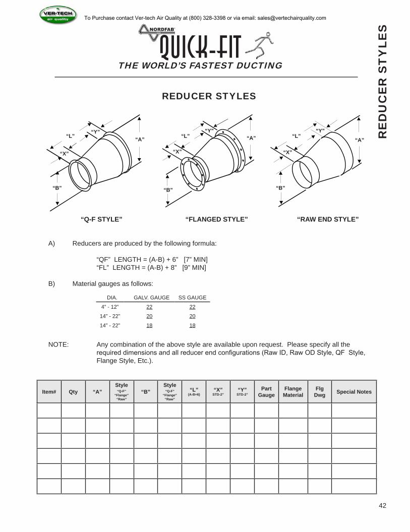
REDUCER STYLES
“Q-F STYLE” “FLANGED STYLE” “RAW END STYLE”
A) Reducers are produced by the following formula:
“QF” LENGTH = (A-B) + 6” [7” MIN] “FL” LENGTH = (A-B) + 8” [9” MIN]
B) Material gauges as follows:
NOTE: Any combination of the above style are available upon request. Please specify all the required dimensions and all reducer end configurations (Raw ID, Raw OD Style, QF Style, Flange Style, Etc.).
42
To Purchase contact Ver-tech Air Quality at (800) 328-3398 or via email: [email protected]
THE WORLD’S FASTEST DUCTINGQuick-Fit
SIZ
ING
BR
AN
CH
ES
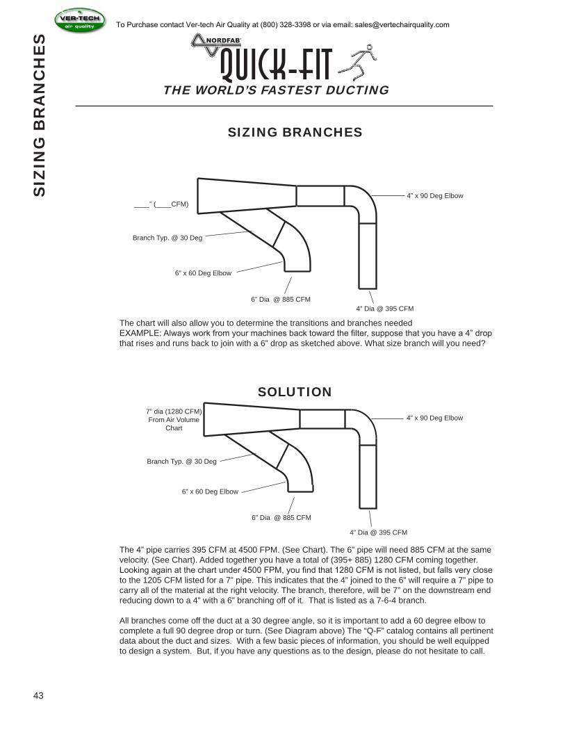
SIZING BRANCHES
____” (____CFM)
Branch Typ. @ 30 Deg
6” x 60 Deg Elbow
6” Dia @ 885 CFM
4” x 90 Deg Elbow
4” Dia @ 395 CFM
7” dia (1280 CFM)From Air Volume
Chart
Branch Typ. @ 30 Deg
6” x 60 Deg Elbow
6” Dia @ 885 CFM
4” Dia @ 395 CFM
4” x 90 Deg Elbow
The chart will also allow you to determine the transitions and branches neededEXAMPLE: Always work from your machines back toward the filter, suppose that you have a 4” drop that rises and runs back to join with a 6” drop as sketched above. What size branch will you need?
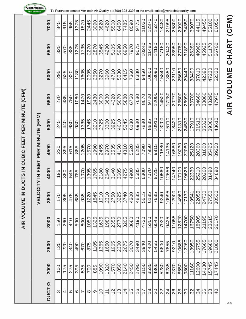
The 4” pipe carries 395 CFM at 4500 FPM. (See Chart). The 6” pipe will need 885 CFM at the same velocity. (See Chart). Added together you have a total of (395+ 885) 1280 CFM coming together. Looking again at the chart under 4500 FPM, you find that 1280 CFM is not listed, but falls very close to the 1205 CFM listed for a 7” pipe. This indicates that the 4” joined to the 6” will require a 7” pipe to carry all of the material at the right velocity. The branch, therefore, will be 7” on the downstream end reducing down to a 4” with a 6” branching off of it. That is listed as a 7-6-4 branch.
All branches come off the duct at a 30 degree angle, so it is important to add a 60 degree elbow to complete a full 90 degree drop or turn. (See Diagram above) The “Q-F” catalog contains all pertinent data about the duct and sizes. With a few basic pieces of information, you should be well equipped to design a system. But, if you have any questions as to the design, please do not hesitate to call.
SOLUTION
43
To Purchase contact Ver-tech Air Quality at (800) 328-3398 or via email: [email protected]
AIR
VO
LUM
E IN
DU
CTS
IN C
UB
IC F
EE
T P
ER
MIN
UTE
(CFM
)
VE
LOC
ITY
IN F
EE
T P
ER
MIN
UTE
(FP
M)
DU
CT
Ø20
0025
0030
0035
0040
0045
0050
0055
0060
0065
0070
00
310
012
515
017
019
522
024
527
029
532
034
54
175
220
260
305
350
395
440
485
525
570
615
527
534
041
047
554
561
568
075
082
088
595
56
395
490
590
685
785
885
980
1080
1180
1275
1375
753
567
080
093
510
7012
0513
3514
7016
0517
3518
708
700
875
1050
1220
1395
1570
1745
1920
2095
2270
2445
988
511
0513
2515
4517
6519
9022
1024
3026
5028
7030
9010
1090
1365
1635
1910
2180
2455
2725
3000
3270
3545
3820
1113
2016
5019
8023
1026
4029
7033
0036
3039
6042
9046
2012
1570
1965
2355
2750
3140
3535
3925
4320
4710
5105
5500
1318
5023
0027
7032
2536
8541
5046
1050
7055
3059
9064
5014
2140
2675
3205
3740
4275
4810
5345
5880
6415
6950
7485
1524
5030
7036
8043
0049
0055
2061
3067
5073
6079
7085
9016
2790
3490
4190
4885
5585
6285
6980
7680
8380
9075
9775
1731
5039
4047
3055
1563
0070
9078
8086
7094
5010
240
1103
018
3535
4420
5300
6185
7070
7950
8835
9720
1060
011
485
1237
020
4365
5455
6545
7635
8725
9815
1091
012
000
1309
014
180
1527
022
5280
6600
7920
9240
1056
011
880
1320
014
520
1584
017
160
1848
024
6285
7855
9425
1099
512
656
1413
515
710
1728
018
850
2042
021
995
2673
7092
1011
055
1290
014
740
1658
018
420
2027
022
110
2395
025
800
2885
5010
685
1282
014
960
1710
019
230
2131
023
500
2565
027
780
2992
030
9800
1226
014
700
1717
019
625
2208
024
530
2699
029
440
3189
034
350
3211
160
1395
016
750
1954
122
330
2512
017
910
3070
033
490
2628
039
070
3412
600
1575
518
905
2205
525
210
2836
031
510
3466
037
810
4096
544
115
3614
130
1766
521
195
2473
028
260
3180
035
325
3886
042
390
4592
549
455
3815
745
1968
023
615
2755
031
490
3542
539
360
4329
547
230
5117
055
100
4017
445
2180
026
170
3053
034
890
3925
043
610
4797
552
330
5670
061
055
AIR
VO
LUM
E C
HA
RT
(C
FM)
44
To Purchase contact Ver-tech Air Quality at (800) 328-3398 or via email: [email protected]

Description of Conveyed Material Velocity FPM Example
Gases 1,000 - 2,000 All Vapors, Gases and Smoke
Fumes 2,000 - 2,500 Welding
Oil Mist 2,000 - 2,500 Oily Vapor or Oily Smoke
Very Fine Light Dust 2,500 - 3,000 Cotton Lint, Litho Powder, Wood Flour
Dry Dusts and Powders 3,500 - 4,000 Light Shavings, Rubber Dust, Soap Dust
Typical Industrial Dust 3,000 - 4,000 Grinding or Buffing Dust, Granite/Brick/Clay Dust
Heavy Dusts 4,000 - 4,500 Heavy or Wet Sawdust, Metal Turnings, Sand Blast Dust, Wood Blocks
Heavy or Moist 4,500 + Moist Cement Dust, Quick-Lime Dust, Sticky Buffing Lint
THE WORLD’S FASTEST DUCTINGQuick-Fit
SIZ
ING
A S
YS
TE
MU
SIN
G T
HE
CH
AR
T
SIZING A “Q-F” SYSTEMNORDFAB offers assistance to those sales people and customers who have never designed a ducting system before. We can assist you in determining the correct duct size and configuration that will supply you with the correct flow.
We have the ability to assist customers in designing a blast-gated system; taking into account flow dynamics that will be affected by blast gates. While blast gates can be used to effectively utilize an undersized filtering system, they can also destroy the flow if not properly placed.
USING THE CFM / FPM CHART
In the following pages, you will find information and a chart that allows you to pick the right size duct for the CFM that is required. Different materials need to be moved at different velocities so as to prevent the material from falling out of the air stream. For example: wood chips and saw dust flow well at 4500 feet per minute. Referring to the chart, you will see that a 4” duct will convey 395 CFM at 4500 FPM. This will mean that a 4” pick-up on a machine will take 395 CFM from your filtering system; or working in reverse, if you know that a machine will require approximately 400 CFM to remove the waste, then you should design a 4” duct for the purpose.
45
To Purchase contact Ver-tech Air Quality at (800) 328-3398 or via email: [email protected]
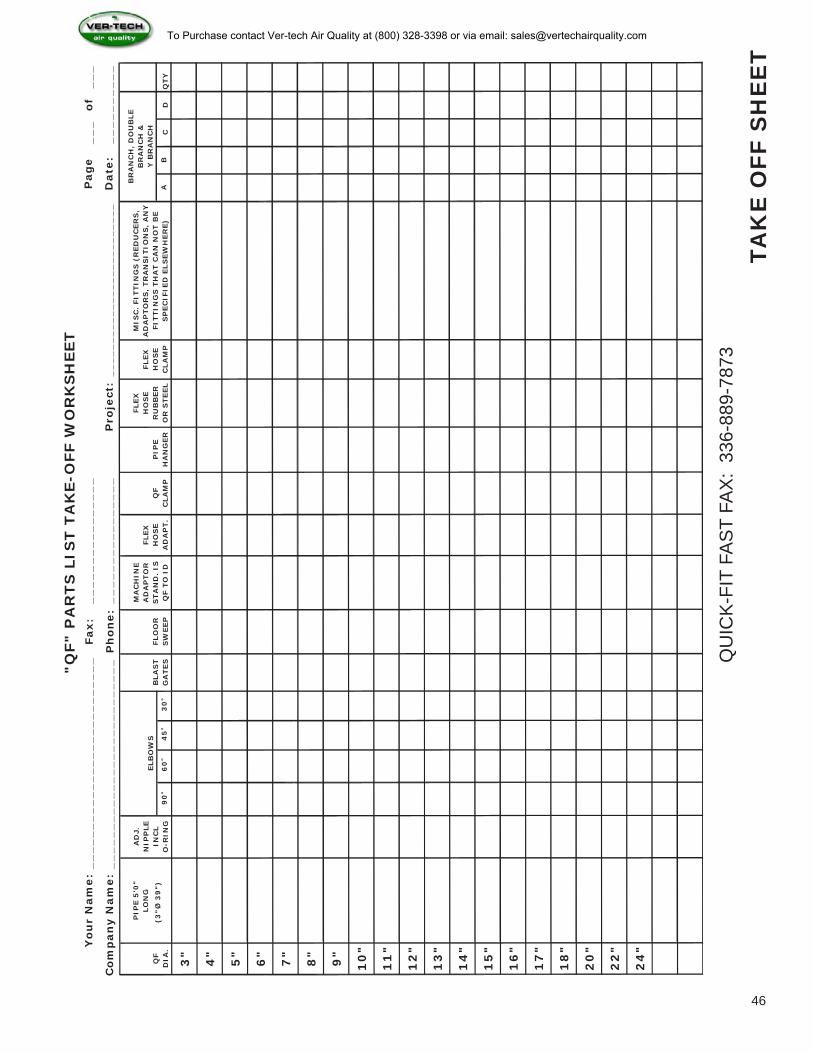
Fax:
__
_o
f_
__
Ph
on
e:
90
o6
0o
45
o3
0o
AB
CD
QTY
3"
4"
5"
6"
7"
8"
9"
10
"
11
"
12
"
13
"
14
"
15
"
16
"
17
"
18
"
20
"
22
"
24
"Yo
ur
Nam
e:
Co
mp
an
y N
am
e:
Pag
e
Date
:
__
__
__
__
__
__
__
__
__
__
__
__
__
_
__
__
__
__
__
__
__
__
__
__
__
__
__
__
__
__
__
__
__
__
__
__
__
__
__
__
_
"Q
F" P
AR
TS
LIS
T T
AK
E-O
FF W
OR
KS
HEET
FLEX
H
OS
E
CLA
MP
QF
DIA
.
PIP
E 5
'0"
LO
NG
BLA
ST
GA
TES
AD
J.
NIP
PLE
INC
L
O
-RIN
GFLO
OR
S
WEEP
MA
CH
INE
AD
AP
TO
R
STA
ND
. IS
Q
F T
O I
D
FLEX
H
OS
E
AD
AP
T.
__
__
__
__
__
ELB
OW
SQ
F
CLA
MP
PIP
E
HA
NG
ER
FLEX
H
OS
E
RU
BB
ER
O
R S
TEEL
__
__
__
__
__
__
__
__
__
__
__
__
__
__
__
__
Pro
ject:
MIS
C.
FIT
TIN
GS
(R
ED
UC
ER
S,
AD
AP
TO
RS
, TR
AN
SIT
ION
S,
AN
Y
FIT
TIN
GS
TH
AT C
AN
NO
T B
E
SP
EC
IFIE
D E
LS
EW
HER
E)
BR
AN
CH
, D
OU
BLE
BR
AN
CH
&
Y B
RA
NC
H(3
Ø 3
9")
"
QU
ICK
-FIT
FA
ST
FAX
: 33
6-88
9-78
73
TAK
E O
FF S
HE
ET
46
To Purchase contact Ver-tech Air Quality at (800) 328-3398 or via email: [email protected]

QUICK-FIT FAST FAX TO: 336-889-7873YES! PLEASE SEND ME A CD ON QUICK- FIT
RUSH! I HAVE A CURRENT PROJECT THAT REQUIRES QUICK-FIT DUCT
I HAVE A FUTURE PROJECT AND NEED MORE INFORMATION
NAME: COMPANY:
ADDRESS: CITY: ST: ZIP:
PHONE: FAX: EMAIL:
CURRENT NEED:
DATE NEEDED:
150 Transit Ave/ PO Box 190 Thomasville, NC 27361-0190Toll Free: 800-532-0830 Fax: 336-889-7873
Web Site: www.nordfab.com
THE WORLD’S FASTEST DUCTINGQuick-Fit
To Purchase contact Ver-tech Air Quality at (800) 328-3398 or via email: [email protected]