Embed Size (px)
Citation preview
To learn more about this book, visit Microsoft Learning at http://www.microsoft.com/MSPress/books/11630.aspx
©
Table of Contents
Acknowledgments . . . . . . . . . . . . . . . . . . . . . . . . . . . . . . . . . . . . . . . . . . . . xiiiIntroduction . . . . . . . . . . . . . . . . . . . . . . . . . . . . . . . . . . . . . . . . . . . . . . . . . .xv
Part I The Network Interface Layer1 Local Area Network (LAN) Technologies . . . . . . . . . . . . . . . . . . . . . . . . . . .3
LAN Encapsulations . . . . . . . . . . . . . . . . . . . . . . . . . . . . . . . . . . . . . . . . . . . . . . . . . . . . . . . . 3
Ethernet . . . . . . . . . . . . . . . . . . . . . . . . . . . . . . . . . . . . . . . . . . . . . . . . . . . . . . . . . . . . . . . . . . 4
Ethernet II . . . . . . . . . . . . . . . . . . . . . . . . . . . . . . . . . . . . . . . . . . . . . . . . . . . . . . . . . . . . 5
IEEE 802.3 . . . . . . . . . . . . . . . . . . . . . . . . . . . . . . . . . . . . . . . . . . . . . . . . . . . . . . . . . . . . 9
IEEE 802.3 SNAP . . . . . . . . . . . . . . . . . . . . . . . . . . . . . . . . . . . . . . . . . . . . . . . . . . . . . 12
Special Bits on Ethernet MAC Addresses . . . . . . . . . . . . . . . . . . . . . . . . . . . . . . . . 14
Token Ring . . . . . . . . . . . . . . . . . . . . . . . . . . . . . . . . . . . . . . . . . . . . . . . . . . . . . . . . . . . . . . 15
IEEE 802.5 . . . . . . . . . . . . . . . . . . . . . . . . . . . . . . . . . . . . . . . . . . . . . . . . . . . . . . . . . . . 16
IEEE 802.5 SNAP . . . . . . . . . . . . . . . . . . . . . . . . . . . . . . . . . . . . . . . . . . . . . . . . . . . . . 19
Special Bits on Token Ring MAC Addresses . . . . . . . . . . . . . . . . . . . . . . . . . . . . . . 20
FDDI . . . . . . . . . . . . . . . . . . . . . . . . . . . . . . . . . . . . . . . . . . . . . . . . . . . . . . . . . . . . . . . . . . . . 21
FDDI Frame Format . . . . . . . . . . . . . . . . . . . . . . . . . . . . . . . . . . . . . . . . . . . . . . . . . . 22
FDDI SNAP . . . . . . . . . . . . . . . . . . . . . . . . . . . . . . . . . . . . . . . . . . . . . . . . . . . . . . . . . . 24
Special Bits on FDDI MAC Addresses . . . . . . . . . . . . . . . . . . . . . . . . . . . . . . . . . . . . 25
IEEE 802.11 . . . . . . . . . . . . . . . . . . . . . . . . . . . . . . . . . . . . . . . . . . . . . . . . . . . . . . . . . . . . . . 26
IEEE 802.11 Frame Format . . . . . . . . . . . . . . . . . . . . . . . . . . . . . . . . . . . . . . . . . . . . . 26
IEEE 802.11 SNAP . . . . . . . . . . . . . . . . . . . . . . . . . . . . . . . . . . . . . . . . . . . . . . . . . . . . 30
Summary . . . . . . . . . . . . . . . . . . . . . . . . . . . . . . . . . . . . . . . . . . . . . . . . . . . . . . . . . . . . . . . . 30
2 Wide Area Network (WAN) Technologies . . . . . . . . . . . . . . . . . . . . . . . . 31WAN Encapsulations . . . . . . . . . . . . . . . . . . . . . . . . . . . . . . . . . . . . . . . . . . . . . . . . . . . . . . 31
Point-to-Point Protocol . . . . . . . . . . . . . . . . . . . . . . . . . . . . . . . . . . . . . . . . . . . . . . . . . . . 32
PPP on Asynchronous Links . . . . . . . . . . . . . . . . . . . . . . . . . . . . . . . . . . . . . . . . . . . 34
PPP on Synchronous Links . . . . . . . . . . . . . . . . . . . . . . . . . . . . . . . . . . . . . . . . . . . . . 35
PPP Maximum Receive Unit . . . . . . . . . . . . . . . . . . . . . . . . . . . . . . . . . . . . . . . . . . . 36
PPP Multilink Protocol . . . . . . . . . . . . . . . . . . . . . . . . . . . . . . . . . . . . . . . . . . . . . . . . 36
Frame Relay . . . . . . . . . . . . . . . . . . . . . . . . . . . . . . . . . . . . . . . . . . . . . . . . . . . . . . . . . . . . . 38
Frame Relay Encapsulation . . . . . . . . . . . . . . . . . . . . . . . . . . . . . . . . . . . . . . . . . . . . 39
Summary . . . . . . . . . . . . . . . . . . . . . . . . . . . . . . . . . . . . . . . . . . . . . . . . . . . . . . . . . . . . . . . . 41
ix
x Table of Contents
3 Address Resolution Protocol (ARP) . . . . . . . . . . . . . . . . . . . . . . . . . . . . . . 43Overview of ARP . . . . . . . . . . . . . . . . . . . . . . . . . . . . . . . . . . . . . . . . . . . . . . . . . . . . . . . . . 43
The ARP or Neighbor Cache . . . . . . . . . . . . . . . . . . . . . . . . . . . . . . . . . . . . . . . . . . . 45
ARP Frame Structure . . . . . . . . . . . . . . . . . . . . . . . . . . . . . . . . . . . . . . . . . . . . . . . . . . . . . 45
ARP in Windows Server 2008 and Windows Vista . . . . . . . . . . . . . . . . . . . . . . . . . . . . . 48
Address Resolution . . . . . . . . . . . . . . . . . . . . . . . . . . . . . . . . . . . . . . . . . . . . . . . . . . 48
Duplicate Address Detection . . . . . . . . . . . . . . . . . . . . . . . . . . . . . . . . . . . . . . . . . . 51
Neighbor Unreachability Detection . . . . . . . . . . . . . . . . . . . . . . . . . . . . . . . . . . . . 54
ARP Registry Values . . . . . . . . . . . . . . . . . . . . . . . . . . . . . . . . . . . . . . . . . . . . . . . . . . 56
Inverse ARP (InARP) . . . . . . . . . . . . . . . . . . . . . . . . . . . . . . . . . . . . . . . . . . . . . . . . . . . . . . 57
Proxy ARP . . . . . . . . . . . . . . . . . . . . . . . . . . . . . . . . . . . . . . . . . . . . . . . . . . . . . . . . . . . . . . . 58
Summary . . . . . . . . . . . . . . . . . . . . . . . . . . . . . . . . . . . . . . . . . . . . . . . . . . . . . . . . . . . . . . . 60
4 Point-to-Point Protocol (PPP) . . . . . . . . . . . . . . . . . . . . . . . . . . . . . . . . . . 61PPP Connection Process . . . . . . . . . . . . . . . . . . . . . . . . . . . . . . . . . . . . . . . . . . . . . . . . . . 62
Phase 1: PPP Configuration Using LCP . . . . . . . . . . . . . . . . . . . . . . . . . . . . . . . . . . 62
Phase 2: Authentication . . . . . . . . . . . . . . . . . . . . . . . . . . . . . . . . . . . . . . . . . . . . . . 62
Phase 3: Callback . . . . . . . . . . . . . . . . . . . . . . . . . . . . . . . . . . . . . . . . . . . . . . . . . . . . 62
Phase 4: Protocol Configuration Using NCPs . . . . . . . . . . . . . . . . . . . . . . . . . . . . 63
PPP Connection Termination . . . . . . . . . . . . . . . . . . . . . . . . . . . . . . . . . . . . . . . . . . . . . . 63
Link Control Protocol . . . . . . . . . . . . . . . . . . . . . . . . . . . . . . . . . . . . . . . . . . . . . . . . . . . . . 63
LCP Options . . . . . . . . . . . . . . . . . . . . . . . . . . . . . . . . . . . . . . . . . . . . . . . . . . . . . . . . 64
LCP Negotiation Process . . . . . . . . . . . . . . . . . . . . . . . . . . . . . . . . . . . . . . . . . . . . . . 66
PPP Authentication Protocols . . . . . . . . . . . . . . . . . . . . . . . . . . . . . . . . . . . . . . . . . . . . . . 67
PAP . . . . . . . . . . . . . . . . . . . . . . . . . . . . . . . . . . . . . . . . . . . . . . . . . . . . . . . . . . . . . . . . 68
CHAP . . . . . . . . . . . . . . . . . . . . . . . . . . . . . . . . . . . . . . . . . . . . . . . . . . . . . . . . . . . . . . 70
MS-CHAP v2 . . . . . . . . . . . . . . . . . . . . . . . . . . . . . . . . . . . . . . . . . . . . . . . . . . . . . . . . 71
EAP . . . . . . . . . . . . . . . . . . . . . . . . . . . . . . . . . . . . . . . . . . . . . . . . . . . . . . . . . . . . . . . . 73
Callback and the Callback Control Protocol . . . . . . . . . . . . . . . . . . . . . . . . . . . . . . . . . . 78
Network Control Protocols . . . . . . . . . . . . . . . . . . . . . . . . . . . . . . . . . . . . . . . . . . . . . . . . 79
IPCP . . . . . . . . . . . . . . . . . . . . . . . . . . . . . . . . . . . . . . . . . . . . . . . . . . . . . . . . . . . . . . . 79
Compression Control Protocol . . . . . . . . . . . . . . . . . . . . . . . . . . . . . . . . . . . . . . . . . 80
Encryption Control Protocol . . . . . . . . . . . . . . . . . . . . . . . . . . . . . . . . . . . . . . . . . . . 82
Network Monitor Example . . . . . . . . . . . . . . . . . . . . . . . . . . . . . . . . . . . . . . . . . . . . . . . . 82
PPP over Ethernet . . . . . . . . . . . . . . . . . . . . . . . . . . . . . . . . . . . . . . . . . . . . . . . . . . . . . . . . 83
PPPoE Discovery Stage . . . . . . . . . . . . . . . . . . . . . . . . . . . . . . . . . . . . . . . . . . . . . . . 84
PPPoE Session Stage . . . . . . . . . . . . . . . . . . . . . . . . . . . . . . . . . . . . . . . . . . . . . . . . . 85
Summary . . . . . . . . . . . . . . . . . . . . . . . . . . . . . . . . . . . . . . . . . . . . . . . . . . . . . . . . . . . . . . . 85

Table of Contents xi
Part II Internet Layer Protocols 5 Internet Protocol (IP). . . . . . . . . . . . . . . . . . . . . . . . . . . . . . . . . . . . . . . . . . 89
Introduction to IP . . . . . . . . . . . . . . . . . . . . . . . . . . . . . . . . . . . . . . . . . . . . . . . . . . . . . . . . 89
IP Services . . . . . . . . . . . . . . . . . . . . . . . . . . . . . . . . . . . . . . . . . . . . . . . . . . . . . . . . . . . 90
IP MTU . . . . . . . . . . . . . . . . . . . . . . . . . . . . . . . . . . . . . . . . . . . . . . . . . . . . . . . . . . . . . 91
The IP Datagram . . . . . . . . . . . . . . . . . . . . . . . . . . . . . . . . . . . . . . . . . . . . . . . . . . . . . . . . . 92
The IP Header . . . . . . . . . . . . . . . . . . . . . . . . . . . . . . . . . . . . . . . . . . . . . . . . . . . . . . . . . . . . 93
Version . . . . . . . . . . . . . . . . . . . . . . . . . . . . . . . . . . . . . . . . . . . . . . . . . . . . . . . . . . . . . 93
Internet Header Length . . . . . . . . . . . . . . . . . . . . . . . . . . . . . . . . . . . . . . . . . . . . . . . 94
Type Of Service . . . . . . . . . . . . . . . . . . . . . . . . . . . . . . . . . . . . . . . . . . . . . . . . . . . . . . 94
Total Length . . . . . . . . . . . . . . . . . . . . . . . . . . . . . . . . . . . . . . . . . . . . . . . . . . . . . . . . . 98
Identification . . . . . . . . . . . . . . . . . . . . . . . . . . . . . . . . . . . . . . . . . . . . . . . . . . . . . . . . 99
Flags . . . . . . . . . . . . . . . . . . . . . . . . . . . . . . . . . . . . . . . . . . . . . . . . . . . . . . . . . . . . . . . 99
Fragment Offset . . . . . . . . . . . . . . . . . . . . . . . . . . . . . . . . . . . . . . . . . . . . . . . . . . . . . 99
Time-To-Live . . . . . . . . . . . . . . . . . . . . . . . . . . . . . . . . . . . . . . . . . . . . . . . . . . . . . . . . 99
Protocol . . . . . . . . . . . . . . . . . . . . . . . . . . . . . . . . . . . . . . . . . . . . . . . . . . . . . . . . . . . 101
Header Checksum . . . . . . . . . . . . . . . . . . . . . . . . . . . . . . . . . . . . . . . . . . . . . . . . . . . 101
Source Address . . . . . . . . . . . . . . . . . . . . . . . . . . . . . . . . . . . . . . . . . . . . . . . . . . . . . . 102
Destination Address. . . . . . . . . . . . . . . . . . . . . . . . . . . . . . . . . . . . . . . . . . . . . . . . . . 102
Options and Padding . . . . . . . . . . . . . . . . . . . . . . . . . . . . . . . . . . . . . . . . . . . . . . . . 102
Fragmentation . . . . . . . . . . . . . . . . . . . . . . . . . . . . . . . . . . . . . . . . . . . . . . . . . . . . . . . . . . 103
Fragmentation Fields. . . . . . . . . . . . . . . . . . . . . . . . . . . . . . . . . . . . . . . . . . . . . . . . . 103
Fragmentation Example . . . . . . . . . . . . . . . . . . . . . . . . . . . . . . . . . . . . . . . . . . . . . . 105
Reassembly Example . . . . . . . . . . . . . . . . . . . . . . . . . . . . . . . . . . . . . . . . . . . . . . . . . 107
Fragmenting a Fragment . . . . . . . . . . . . . . . . . . . . . . . . . . . . . . . . . . . . . . . . . . . . . 109
Avoiding Fragmentation. . . . . . . . . . . . . . . . . . . . . . . . . . . . . . . . . . . . . . . . . . . . . . 109
Fragmentation and TCP/IP for Windows Server 2008 and Windows Vista . . . 112
IP Options . . . . . . . . . . . . . . . . . . . . . . . . . . . . . . . . . . . . . . . . . . . . . . . . . . . . . . . . . . . . . . 112
Copy. . . . . . . . . . . . . . . . . . . . . . . . . . . . . . . . . . . . . . . . . . . . . . . . . . . . . . . . . . . . . . . 113
Option Class . . . . . . . . . . . . . . . . . . . . . . . . . . . . . . . . . . . . . . . . . . . . . . . . . . . . . . . . 113
Option Number . . . . . . . . . . . . . . . . . . . . . . . . . . . . . . . . . . . . . . . . . . . . . . . . . . . . . 113
Strict and Loose Source Routing . . . . . . . . . . . . . . . . . . . . . . . . . . . . . . . . . . . . . . . 116
IP Router Alert . . . . . . . . . . . . . . . . . . . . . . . . . . . . . . . . . . . . . . . . . . . . . . . . . . . . . . 120
Internet Timestamp . . . . . . . . . . . . . . . . . . . . . . . . . . . . . . . . . . . . . . . . . . . . . . . . . . 121
Summary . . . . . . . . . . . . . . . . . . . . . . . . . . . . . . . . . . . . . . . . . . . . . . . . . . . . . . . . . . . . . . . 123
6 Internet Control Message Protocol (ICMP) . . . . . . . . . . . . . . . . . . . . . . 125ICMP Message Structure . . . . . . . . . . . . . . . . . . . . . . . . . . . . . . . . . . . . . . . . . . . . . . . . . . 126
xii Table of Contents
ICMP Messages . . . . . . . . . . . . . . . . . . . . . . . . . . . . . . . . . . . . . . . . . . . . . . . . . . . . . . . . . 127
ICMP Echo and Echo Reply . . . . . . . . . . . . . . . . . . . . . . . . . . . . . . . . . . . . . . . . . . . 127
ICMP Destination Unreachable . . . . . . . . . . . . . . . . . . . . . . . . . . . . . . . . . . . . . . . . 129
PMTU Discovery . . . . . . . . . . . . . . . . . . . . . . . . . . . . . . . . . . . . . . . . . . . . . . . . . . . . 133
ICMP Source Quench . . . . . . . . . . . . . . . . . . . . . . . . . . . . . . . . . . . . . . . . . . . . . . . . 136
ICMP Redirect . . . . . . . . . . . . . . . . . . . . . . . . . . . . . . . . . . . . . . . . . . . . . . . . . . . . . . 137
ICMP Router Discovery. . . . . . . . . . . . . . . . . . . . . . . . . . . . . . . . . . . . . . . . . . . . . . . 141
ICMP Time Exceeded . . . . . . . . . . . . . . . . . . . . . . . . . . . . . . . . . . . . . . . . . . . . . . . . 144
ICMP Parameter Problem . . . . . . . . . . . . . . . . . . . . . . . . . . . . . . . . . . . . . . . . . . . . 145
ICMP Address Mask Request and Address Mask Reply. . . . . . . . . . . . . . . . . . . . 146
Ping.exe Tool . . . . . . . . . . . . . . . . . . . . . . . . . . . . . . . . . . . . . . . . . . . . . . . . . . . . . . . . . . . 148
Ping Options . . . . . . . . . . . . . . . . . . . . . . . . . . . . . . . . . . . . . . . . . . . . . . . . . . . . . . . 148
Tracert.exe Tool . . . . . . . . . . . . . . . . . . . . . . . . . . . . . . . . . . . . . . . . . . . . . . . . . . . . . . . . . 150
Tracert Options . . . . . . . . . . . . . . . . . . . . . . . . . . . . . . . . . . . . . . . . . . . . . . . . . . . . . 152
Pathping.exe Tool . . . . . . . . . . . . . . . . . . . . . . . . . . . . . . . . . . . . . . . . . . . . . . . . . . . . . . . 153
Pathping Options . . . . . . . . . . . . . . . . . . . . . . . . . . . . . . . . . . . . . . . . . . . . . . . . . . . 155
Summary . . . . . . . . . . . . . . . . . . . . . . . . . . . . . . . . . . . . . . . . . . . . . . . . . . . . . . . . . . . . . . . 155
7 Internet Group Management Protocol (IGMP) . . . . . . . . . . . . . . . . . . . 157Introduction to IP Multicast and IGMP . . . . . . . . . . . . . . . . . . . . . . . . . . . . . . . . . . . . . 157
IP Multicasting Overview . . . . . . . . . . . . . . . . . . . . . . . . . . . . . . . . . . . . . . . . . . . . . 158
Host Support . . . . . . . . . . . . . . . . . . . . . . . . . . . . . . . . . . . . . . . . . . . . . . . . . . . . . . . 158
Router Support . . . . . . . . . . . . . . . . . . . . . . . . . . . . . . . . . . . . . . . . . . . . . . . . . . . . . 160
The Multicast-Enabled IP Internetwork . . . . . . . . . . . . . . . . . . . . . . . . . . . . . . . . . 161
The Internet’s Multicast-Enabled Backbone . . . . . . . . . . . . . . . . . . . . . . . . . . . . . 162
IGMP Message Structure . . . . . . . . . . . . . . . . . . . . . . . . . . . . . . . . . . . . . . . . . . . . . . . . . 163
IGMP Version 1 (IGMPv1) . . . . . . . . . . . . . . . . . . . . . . . . . . . . . . . . . . . . . . . . . . . . 163
IGMP Version 2 (IGMPv2) . . . . . . . . . . . . . . . . . . . . . . . . . . . . . . . . . . . . . . . . . . . . 166
IGMP Version 3 (IGMPv3) . . . . . . . . . . . . . . . . . . . . . . . . . . . . . . . . . . . . . . . . . . . . 169
IGMP in Windows Server 2008 and Windows Vista . . . . . . . . . . . . . . . . . . . . . . . . . . . 173
TCP/IP Protocol . . . . . . . . . . . . . . . . . . . . . . . . . . . . . . . . . . . . . . . . . . . . . . . . . . . . . 173
Routing And Remote Access Service . . . . . . . . . . . . . . . . . . . . . . . . . . . . . . . . . . . 174
Summary . . . . . . . . . . . . . . . . . . . . . . . . . . . . . . . . . . . . . . . . . . . . . . . . . . . . . . . . . . . . . . . 176
8 Internet Protocol Version 6 (IPv6). . . . . . . . . . . . . . . . . . . . . . . . . . . . . . 179The Disadvantages of IPv4 . . . . . . . . . . . . . . . . . . . . . . . . . . . . . . . . . . . . . . . . . . . . . . . . 179
IPv6 Addressing . . . . . . . . . . . . . . . . . . . . . . . . . . . . . . . . . . . . . . . . . . . . . . . . . . . . . . . . . 181
Basics of IPv6 Address Syntax . . . . . . . . . . . . . . . . . . . . . . . . . . . . . . . . . . . . . . . . . 182
Types of Addresses . . . . . . . . . . . . . . . . . . . . . . . . . . . . . . . . . . . . . . . . . . . . . . . . . . 182
Table of Contents xiii
Types of Unicast Addresses . . . . . . . . . . . . . . . . . . . . . . . . . . . . . . . . . . . . . . . . . . . 183
IPv6 Interface Identifiers . . . . . . . . . . . . . . . . . . . . . . . . . . . . . . . . . . . . . . . . . . . . . . 183
DNS Support. . . . . . . . . . . . . . . . . . . . . . . . . . . . . . . . . . . . . . . . . . . . . . . . . . . . . . . . 184
Core Protocols of IPv6 . . . . . . . . . . . . . . . . . . . . . . . . . . . . . . . . . . . . . . . . . . . . . . . . . . . . 184
IPv6. . . . . . . . . . . . . . . . . . . . . . . . . . . . . . . . . . . . . . . . . . . . . . . . . . . . . . . . . . . . . . . . 184
ICMPv6 . . . . . . . . . . . . . . . . . . . . . . . . . . . . . . . . . . . . . . . . . . . . . . . . . . . . . . . . . . . . 185
Neighbor Discovery . . . . . . . . . . . . . . . . . . . . . . . . . . . . . . . . . . . . . . . . . . . . . . . . . . 185
Multicast Listener Discovery. . . . . . . . . . . . . . . . . . . . . . . . . . . . . . . . . . . . . . . . . . . 186
Differences Between IPv4 and IPv6 . . . . . . . . . . . . . . . . . . . . . . . . . . . . . . . . . . . . . . . . . 186
Summary . . . . . . . . . . . . . . . . . . . . . . . . . . . . . . . . . . . . . . . . . . . . . . . . . . . . . . . . . . . . . . . 187
Part III Transport Layer Protocols 9 User Datagram Protocol . . . . . . . . . . . . . . . . . . . . . . . . . . . . . . . . . . . . . . 191
Introduction to UDP. . . . . . . . . . . . . . . . . . . . . . . . . . . . . . . . . . . . . . . . . . . . . . . . . . . . . . 191
Uses for UDP . . . . . . . . . . . . . . . . . . . . . . . . . . . . . . . . . . . . . . . . . . . . . . . . . . . . . . . . . . . . 192
The UDP Message. . . . . . . . . . . . . . . . . . . . . . . . . . . . . . . . . . . . . . . . . . . . . . . . . . . . . . . . 193
The UDP Header . . . . . . . . . . . . . . . . . . . . . . . . . . . . . . . . . . . . . . . . . . . . . . . . . . . . . . . . . 193
UDP Ports. . . . . . . . . . . . . . . . . . . . . . . . . . . . . . . . . . . . . . . . . . . . . . . . . . . . . . . . . . . . . . . 195
The UDP Pseudo Header . . . . . . . . . . . . . . . . . . . . . . . . . . . . . . . . . . . . . . . . . . . . . . . . . . 196
Summary . . . . . . . . . . . . . . . . . . . . . . . . . . . . . . . . . . . . . . . . . . . . . . . . . . . . . . . . . . . . . . . 197
10 Transmission Control Protocol (TCP) Basics. . . . . . . . . . . . . . . . . . . . . . 199Introduction to TCP . . . . . . . . . . . . . . . . . . . . . . . . . . . . . . . . . . . . . . . . . . . . . . . . . . . . . . 199
The TCP Segment . . . . . . . . . . . . . . . . . . . . . . . . . . . . . . . . . . . . . . . . . . . . . . . . . . . . . . . . 200
The TCP Header . . . . . . . . . . . . . . . . . . . . . . . . . . . . . . . . . . . . . . . . . . . . . . . . . . . . . . . . . 201
TCP Ports . . . . . . . . . . . . . . . . . . . . . . . . . . . . . . . . . . . . . . . . . . . . . . . . . . . . . . . . . . . . . . . 204
TCP Flags . . . . . . . . . . . . . . . . . . . . . . . . . . . . . . . . . . . . . . . . . . . . . . . . . . . . . . . . . . . . . . . 205
The TCP Pseudo Header . . . . . . . . . . . . . . . . . . . . . . . . . . . . . . . . . . . . . . . . . . . . . . . . . . 207
TCP Urgent Data. . . . . . . . . . . . . . . . . . . . . . . . . . . . . . . . . . . . . . . . . . . . . . . . . . . . . . . . . 208
TCP Options. . . . . . . . . . . . . . . . . . . . . . . . . . . . . . . . . . . . . . . . . . . . . . . . . . . . . . . . . . . . . 210
End Of Option List and No Operation . . . . . . . . . . . . . . . . . . . . . . . . . . . . . . . . . . 210
Maximum Segment Size Option . . . . . . . . . . . . . . . . . . . . . . . . . . . . . . . . . . . . . . . 210
TCP Window Scale Option . . . . . . . . . . . . . . . . . . . . . . . . . . . . . . . . . . . . . . . . . . . . 213
Selective Acknowledgment Option. . . . . . . . . . . . . . . . . . . . . . . . . . . . . . . . . . . . . 215
TCP Timestamps Option . . . . . . . . . . . . . . . . . . . . . . . . . . . . . . . . . . . . . . . . . . . . . . 218
Summary . . . . . . . . . . . . . . . . . . . . . . . . . . . . . . . . . . . . . . . . . . . . . . . . . . . . . . . . . . . . . . . 221
11 Transmission Control Protocol (TCP) Connections . . . . . . . . . . . . . . . . 223The TCP Connection. . . . . . . . . . . . . . . . . . . . . . . . . . . . . . . . . . . . . . . . . . . . . . . . . . . . . . 223
xiv Table of Contents
TCP Connection Establishment . . . . . . . . . . . . . . . . . . . . . . . . . . . . . . . . . . . . . . . . . . . . 224
Segment 1: The Synchronize (SYN) Segment . . . . . . . . . . . . . . . . . . . . . . . . . . . . 225
Segment 2: The SYN-ACK Segment . . . . . . . . . . . . . . . . . . . . . . . . . . . . . . . . . . . . 227
Segment 3: The ACK Segment . . . . . . . . . . . . . . . . . . . . . . . . . . . . . . . . . . . . . . . . 228
Results of the TCP Connection . . . . . . . . . . . . . . . . . . . . . . . . . . . . . . . . . . . . . . . . 229
TCP Half-Open Connections . . . . . . . . . . . . . . . . . . . . . . . . . . . . . . . . . . . . . . . . . . . . . . 230
TCP Connection Maintenance . . . . . . . . . . . . . . . . . . . . . . . . . . . . . . . . . . . . . . . . . . . . . 232
TCP Connection Termination. . . . . . . . . . . . . . . . . . . . . . . . . . . . . . . . . . . . . . . . . . . . . . 234
Segment 1: The FIN-ACK from TCP Peer 1 . . . . . . . . . . . . . . . . . . . . . . . . . . . . . . 234
Segment 2: The ACK from TCP Peer 2 . . . . . . . . . . . . . . . . . . . . . . . . . . . . . . . . . . 235
Segment 3: The FIN-ACK from TCP Peer 2 . . . . . . . . . . . . . . . . . . . . . . . . . . . . . . 236
Segment 4: The ACK from TCP Peer 1 . . . . . . . . . . . . . . . . . . . . . . . . . . . . . . . . . . 237
TCP Connection Reset . . . . . . . . . . . . . . . . . . . . . . . . . . . . . . . . . . . . . . . . . . . . . . . . . . . . 238
TCP Connection States . . . . . . . . . . . . . . . . . . . . . . . . . . . . . . . . . . . . . . . . . . . . . . . . . . . 240
Controlling the TIME WAIT state in Windows Server 2008 andWindows Vista . . . . . . . . . . . . . . . . . . . . . . . . . . . . . . . . . . . . . . . . . . . . . . . . . . . . . 242
Summary . . . . . . . . . . . . . . . . . . . . . . . . . . . . . . . . . . . . . . . . . . . . . . . . . . . . . . . . . . . . . . . 243
12 Transmission Control Protocol (TCP) Data Flow . . . . . . . . . . . . . . . . . . 245Basic TCP Data Flow Behavior . . . . . . . . . . . . . . . . . . . . . . . . . . . . . . . . . . . . . . . . . . . . . 245
TCP Acknowledgments . . . . . . . . . . . . . . . . . . . . . . . . . . . . . . . . . . . . . . . . . . . . . . . . . . . 246
Delayed Acknowledgments . . . . . . . . . . . . . . . . . . . . . . . . . . . . . . . . . . . . . . . . . . . 246
Cumulative for Contiguous Data . . . . . . . . . . . . . . . . . . . . . . . . . . . . . . . . . . . . . . 247
Selective for Noncontiguous Data . . . . . . . . . . . . . . . . . . . . . . . . . . . . . . . . . . . . . 248
TCP Sliding Windows . . . . . . . . . . . . . . . . . . . . . . . . . . . . . . . . . . . . . . . . . . . . . . . . . . . . 249
Send Window. . . . . . . . . . . . . . . . . . . . . . . . . . . . . . . . . . . . . . . . . . . . . . . . . . . . . . . 249
Receive Window . . . . . . . . . . . . . . . . . . . . . . . . . . . . . . . . . . . . . . . . . . . . . . . . . . . . 252
Receive Window Auto-Tuning . . . . . . . . . . . . . . . . . . . . . . . . . . . . . . . . . . . . . . . . 255
Small Segments . . . . . . . . . . . . . . . . . . . . . . . . . . . . . . . . . . . . . . . . . . . . . . . . . . . . . . . . . 257
The Nagle Algorithm . . . . . . . . . . . . . . . . . . . . . . . . . . . . . . . . . . . . . . . . . . . . . . . . 257
Silly Window Syndrome . . . . . . . . . . . . . . . . . . . . . . . . . . . . . . . . . . . . . . . . . . . . . . 258
Sender-Side Flow Control. . . . . . . . . . . . . . . . . . . . . . . . . . . . . . . . . . . . . . . . . . . . . . . . . 259
Slow Start Algorithm. . . . . . . . . . . . . . . . . . . . . . . . . . . . . . . . . . . . . . . . . . . . . . . . . 260
Congestion Avoidance Algorithm . . . . . . . . . . . . . . . . . . . . . . . . . . . . . . . . . . . . . 262
Compound TCP . . . . . . . . . . . . . . . . . . . . . . . . . . . . . . . . . . . . . . . . . . . . . . . . . . . . . 264
Explicit Congestion Notification . . . . . . . . . . . . . . . . . . . . . . . . . . . . . . . . . . . . . . . 265
Limited Transmit . . . . . . . . . . . . . . . . . . . . . . . . . . . . . . . . . . . . . . . . . . . . . . . . . . . . 268
Summary . . . . . . . . . . . . . . . . . . . . . . . . . . . . . . . . . . . . . . . . . . . . . . . . . . . . . . . . . . . . . . . 268
Table of Contents xv
13 Transmission Control Protocol (TCP) Retransmission and Time-Out 271Retransmission Time-Out and Round-Trip Time. . . . . . . . . . . . . . . . . . . . . . . . . . . . . . 271
Congestion Collapse . . . . . . . . . . . . . . . . . . . . . . . . . . . . . . . . . . . . . . . . . . . . . . . . . 273
Retransmission Behavior . . . . . . . . . . . . . . . . . . . . . . . . . . . . . . . . . . . . . . . . . . . . . . . . . . 273
Retransmission Behavior for New Connections . . . . . . . . . . . . . . . . . . . . . . . . . . 275
Dead Gateway Detection . . . . . . . . . . . . . . . . . . . . . . . . . . . . . . . . . . . . . . . . . . . . . 275
Forward RTO-Recovery . . . . . . . . . . . . . . . . . . . . . . . . . . . . . . . . . . . . . . . . . . . . . . . 277
Using the Selective Acknowledgment (SACK) TCP Option . . . . . . . . . . . . . . . . . 278
Calculating the RTO . . . . . . . . . . . . . . . . . . . . . . . . . . . . . . . . . . . . . . . . . . . . . . . . . . . . . . 279
Using the TCP Timestamps Option . . . . . . . . . . . . . . . . . . . . . . . . . . . . . . . . . . . . . 280
Karn’s Algorithm . . . . . . . . . . . . . . . . . . . . . . . . . . . . . . . . . . . . . . . . . . . . . . . . . . . . 284
Karn’s Algorithm and the Timestamps Option . . . . . . . . . . . . . . . . . . . . . . . . . . . 285
Fast Retransmit and Fast Recovery . . . . . . . . . . . . . . . . . . . . . . . . . . . . . . . . . . . . . . . . . 286
Fast Recovery . . . . . . . . . . . . . . . . . . . . . . . . . . . . . . . . . . . . . . . . . . . . . . . . . . . . . . . 288
Summary . . . . . . . . . . . . . . . . . . . . . . . . . . . . . . . . . . . . . . . . . . . . . . . . . . . . . . . . . . . . . . . 289
Part IV Application Layer Protocols and Services 14 Dynamic Host Configuration Protocol (DHCP) . . . . . . . . . . . . . . . . . . . 293
DHCP Messages . . . . . . . . . . . . . . . . . . . . . . . . . . . . . . . . . . . . . . . . . . . . . . . . . . . . . . . . . 293
DHCP Message Format . . . . . . . . . . . . . . . . . . . . . . . . . . . . . . . . . . . . . . . . . . . . . . . 294
DHCP Options . . . . . . . . . . . . . . . . . . . . . . . . . . . . . . . . . . . . . . . . . . . . . . . . . . . . . . 297
DHCP Message Exchanges . . . . . . . . . . . . . . . . . . . . . . . . . . . . . . . . . . . . . . . . . . . . . . . . 301
Obtaining an Initial Lease . . . . . . . . . . . . . . . . . . . . . . . . . . . . . . . . . . . . . . . . . . . . . 301
Renewing a Lease. . . . . . . . . . . . . . . . . . . . . . . . . . . . . . . . . . . . . . . . . . . . . . . . . . . . 308
Changing Subnets . . . . . . . . . . . . . . . . . . . . . . . . . . . . . . . . . . . . . . . . . . . . . . . . . . . 308
Detecting Unauthorized DHCP Servers . . . . . . . . . . . . . . . . . . . . . . . . . . . . . . . . . 309
Updating DNS Entries . . . . . . . . . . . . . . . . . . . . . . . . . . . . . . . . . . . . . . . . . . . . . . . . 310
Summary . . . . . . . . . . . . . . . . . . . . . . . . . . . . . . . . . . . . . . . . . . . . . . . . . . . . . . . . . . . . . . . 311
15 Domain Name System. . . . . . . . . . . . . . . . . . . . . . . . . . . . . . . . . . . . . . . . 313Sample of an AA (section1, H1, heading1) Heading Entry . . . . . . . . . . . . . . . . . . . . . 000
DNS Messages. . . . . . . . . . . . . . . . . . . . . . . . . . . . . . . . . . . . . . . . . . . . . . . . . . . . . . . . . . . 313
DNS Name Query Request and Name Query Response Messages . . . . . . . . . . 314
DNS Update and Update Response Messages . . . . . . . . . . . . . . . . . . . . . . . . . . . 319
DNS Message Exchanges. . . . . . . . . . . . . . . . . . . . . . . . . . . . . . . . . . . . . . . . . . . . . . . . . . 323
Resolving Names to Addresses . . . . . . . . . . . . . . . . . . . . . . . . . . . . . . . . . . . . . . . . 323
Resolving Addresses to Names . . . . . . . . . . . . . . . . . . . . . . . . . . . . . . . . . . . . . . . . 325
Resolving Aliases . . . . . . . . . . . . . . . . . . . . . . . . . . . . . . . . . . . . . . . . . . . . . . . . . . . . 326

xvi Table of Contents
Dynamically Updating DNS . . . . . . . . . . . . . . . . . . . . . . . . . . . . . . . . . . . . . . . . . . . 327
Transferring Zone Information Between DNS Servers. . . . . . . . . . . . . . . . . . . . . 330
Summary . . . . . . . . . . . . . . . . . . . . . . . . . . . . . . . . . . . . . . . . . . . . . . . . . . . . . . . . . . . . . . 331
16 Windows Internet Name Service . . . . . . . . . . . . . . . . . . . . . . . . . . . . . . 333NetBT Name Service Messages . . . . . . . . . . . . . . . . . . . . . . . . . . . . . . . . . . . . . . . . . . . . 333
NetBIOS Name Service Messages. . . . . . . . . . . . . . . . . . . . . . . . . . . . . . . . . . . . . . 334
NetBIOS Name Representation. . . . . . . . . . . . . . . . . . . . . . . . . . . . . . . . . . . . . . . . 338
Question RR Format . . . . . . . . . . . . . . . . . . . . . . . . . . . . . . . . . . . . . . . . . . . . . . . . . 340
WINS Client and Server Message Exchanges . . . . . . . . . . . . . . . . . . . . . . . . . . . . . . . . 344
Resolving NetBIOS Names to IPv4 Addresses. . . . . . . . . . . . . . . . . . . . . . . . . . . . 344
Registering NetBIOS Names . . . . . . . . . . . . . . . . . . . . . . . . . . . . . . . . . . . . . . . . . . 346
Refreshing NetBIOS Names . . . . . . . . . . . . . . . . . . . . . . . . . . . . . . . . . . . . . . . . . . . 349
Releasing NetBIOS Names . . . . . . . . . . . . . . . . . . . . . . . . . . . . . . . . . . . . . . . . . . . . 351
Summary . . . . . . . . . . . . . . . . . . . . . . . . . . . . . . . . . . . . . . . . . . . . . . . . . . . . . . . . . . . . . . . 352
17 Remote Authentication Dial-In User Service (RADIUS) . . . . . . . . . . . . 353RADIUS Messages . . . . . . . . . . . . . . . . . . . . . . . . . . . . . . . . . . . . . . . . . . . . . . . . . . . . . . . 353
RADIUS Message Structure . . . . . . . . . . . . . . . . . . . . . . . . . . . . . . . . . . . . . . . . . . . 355
RADIUS Attributes . . . . . . . . . . . . . . . . . . . . . . . . . . . . . . . . . . . . . . . . . . . . . . . . . . . 356
Vendor-Specific Attributes. . . . . . . . . . . . . . . . . . . . . . . . . . . . . . . . . . . . . . . . . . . . 362
RADIUS Message Exchanges . . . . . . . . . . . . . . . . . . . . . . . . . . . . . . . . . . . . . . . . . . . . . . 364
Authentication of Network Access . . . . . . . . . . . . . . . . . . . . . . . . . . . . . . . . . . . . . 364
Accounting of Network Access . . . . . . . . . . . . . . . . . . . . . . . . . . . . . . . . . . . . . . . . 367
RADIUS Proxy Forwarding . . . . . . . . . . . . . . . . . . . . . . . . . . . . . . . . . . . . . . . . . . . . 370
Summary . . . . . . . . . . . . . . . . . . . . . . . . . . . . . . . . . . . . . . . . . . . . . . . . . . . . . . . . . . . . . . . 372
18 Internet Protocol Security (IPsec) . . . . . . . . . . . . . . . . . . . . . . . . . . . . . . 373IPsec Headers . . . . . . . . . . . . . . . . . . . . . . . . . . . . . . . . . . . . . . . . . . . . . . . . . . . . . . . . . . . 373
Authentication Header . . . . . . . . . . . . . . . . . . . . . . . . . . . . . . . . . . . . . . . . . . . . . . . 374
Encapsulating Security Payload (ESP). . . . . . . . . . . . . . . . . . . . . . . . . . . . . . . . . . . 378
IPsec and Security Associations . . . . . . . . . . . . . . . . . . . . . . . . . . . . . . . . . . . . . . . . . . . . 383
Internet Key Exchange . . . . . . . . . . . . . . . . . . . . . . . . . . . . . . . . . . . . . . . . . . . . . . . . . . . 385
ISAKMP Message Structure . . . . . . . . . . . . . . . . . . . . . . . . . . . . . . . . . . . . . . . . . . . . . . . 385
ISAKMP Header . . . . . . . . . . . . . . . . . . . . . . . . . . . . . . . . . . . . . . . . . . . . . . . . . . . . . 385
SA Payload . . . . . . . . . . . . . . . . . . . . . . . . . . . . . . . . . . . . . . . . . . . . . . . . . . . . . . . . . 388
Proposal Payload. . . . . . . . . . . . . . . . . . . . . . . . . . . . . . . . . . . . . . . . . . . . . . . . . . . . 389
Transform Payload . . . . . . . . . . . . . . . . . . . . . . . . . . . . . . . . . . . . . . . . . . . . . . . . . . 390
Vendor ID Payload . . . . . . . . . . . . . . . . . . . . . . . . . . . . . . . . . . . . . . . . . . . . . . . . . . 392
Nonce Payload. . . . . . . . . . . . . . . . . . . . . . . . . . . . . . . . . . . . . . . . . . . . . . . . . . . . . . 393

Table of Contents xvii
Key Exchange Payload . . . . . . . . . . . . . . . . . . . . . . . . . . . . . . . . . . . . . . . . . . . . . . . 393
Notification Payload . . . . . . . . . . . . . . . . . . . . . . . . . . . . . . . . . . . . . . . . . . . . . . . . . 394
Delete Payload . . . . . . . . . . . . . . . . . . . . . . . . . . . . . . . . . . . . . . . . . . . . . . . . . . . . . . 395
Identification Payload . . . . . . . . . . . . . . . . . . . . . . . . . . . . . . . . . . . . . . . . . . . . . . . . 396
Hash Payload . . . . . . . . . . . . . . . . . . . . . . . . . . . . . . . . . . . . . . . . . . . . . . . . . . . . . . . 396
Certificate Request Payload . . . . . . . . . . . . . . . . . . . . . . . . . . . . . . . . . . . . . . . . . . . 397
Certificate Payload. . . . . . . . . . . . . . . . . . . . . . . . . . . . . . . . . . . . . . . . . . . . . . . . . . . 398
Signature Payload . . . . . . . . . . . . . . . . . . . . . . . . . . . . . . . . . . . . . . . . . . . . . . . . . . . 398
Main Mode Negotiation . . . . . . . . . . . . . . . . . . . . . . . . . . . . . . . . . . . . . . . . . . . . . . . . . . 399
Quick Mode Negotiation . . . . . . . . . . . . . . . . . . . . . . . . . . . . . . . . . . . . . . . . . . . . . . . . . 399
Authenticated Internet Protocol (AuthIP). . . . . . . . . . . . . . . . . . . . . . . . . . . . . . . . . . . . 401
AuthIP Messages . . . . . . . . . . . . . . . . . . . . . . . . . . . . . . . . . . . . . . . . . . . . . . . . . . . . 401
AuthIP and IKE Coexistence . . . . . . . . . . . . . . . . . . . . . . . . . . . . . . . . . . . . . . . . . . . 401
IPsec NAT Traversal . . . . . . . . . . . . . . . . . . . . . . . . . . . . . . . . . . . . . . . . . . . . . . . . . . . . . . 404
Summary . . . . . . . . . . . . . . . . . . . . . . . . . . . . . . . . . . . . . . . . . . . . . . . . . . . . . . . . . . . . . . . 406
19 Virtual Private Networks (VPNs) . . . . . . . . . . . . . . . . . . . . . . . . . . . . . . . 407PPTP . . . . . . . . . . . . . . . . . . . . . . . . . . . . . . . . . . . . . . . . . . . . . . . . . . . . . . . . . . . . . . . . . . . 407
PPTP Data Encapsulation . . . . . . . . . . . . . . . . . . . . . . . . . . . . . . . . . . . . . . . . . . . . . 408
PPTP Control Connection . . . . . . . . . . . . . . . . . . . . . . . . . . . . . . . . . . . . . . . . . . . . . 411
L2TP/IPsec . . . . . . . . . . . . . . . . . . . . . . . . . . . . . . . . . . . . . . . . . . . . . . . . . . . . . . . . . . . . . . 413
L2TP/IPsec Data Encapsulation . . . . . . . . . . . . . . . . . . . . . . . . . . . . . . . . . . . . . . . . 413
L2TP Control Connection . . . . . . . . . . . . . . . . . . . . . . . . . . . . . . . . . . . . . . . . . . . . . 416
SSTP . . . . . . . . . . . . . . . . . . . . . . . . . . . . . . . . . . . . . . . . . . . . . . . . . . . . . . . . . . . . . . . . . . . 418
SSTP-based VPN Connection Creation Process . . . . . . . . . . . . . . . . . . . . . . . . . . 419
Summary . . . . . . . . . . . . . . . . . . . . . . . . . . . . . . . . . . . . . . . . . . . . . . . . . . . . . . . . . . . . . . . 420
Appendix A: Internet Protocol (IP) Addressing. . . . . . . . . . . . . . . . . . . 421
Types of IP Addresses . . . . . . . . . . . . . . . . . . . . . . . . . . . . . . . . . . . . . . . . . . . . . . . . . . . 421
Expressing IP Addresses . . . . . . . . . . . . . . . . . . . . . . . . . . . . . . . . . . . . . . . . . . . . . . . . . . 421
Converting from Binary to Decimal . . . . . . . . . . . . . . . . . . . . . . . . . . . . . . . . . . . . 422
Converting from Decimal to Binary . . . . . . . . . . . . . . . . . . . . . . . . . . . . . . . . . . . 423
IP Addresses in the IP Header . . . . . . . . . . . . . . . . . . . . . . . . . . . . . . . . . . . . . . . . . 423
Unicast IP Addresses . . . . . . . . . . . . . . . . . . . . . . . . . . . . . . . . . . . . . . . . . . . . . . . . . . . . 423
A History Lesson: IP Address Classes. . . . . . . . . . . . . . . . . . . . . . . . . . . . . . . . . . . 424
Rules for Enumerating Address Prefixes . . . . . . . . . . . . . . . . . . . . . . . . . . . . . . . . 426
Rules for Enumerating Usable Host IDs . . . . . . . . . . . . . . . . . . . . . . . . . . . . . . . . . 426
xviii Table of Contents
Subnets and the Subnet Mask . . . . . . . . . . . . . . . . . . . . . . . . . . . . . . . . . . . . . . . . 427
How to Subnet . . . . . . . . . . . . . . . . . . . . . . . . . . . . . . . . . . . . . . . . . . . . . . . . . . . . . 431
Variable-Length Subnetting . . . . . . . . . . . . . . . . . . . . . . . . . . . . . . . . . . . . . . . . . . 440
Supernetting and CIDR . . . . . . . . . . . . . . . . . . . . . . . . . . . . . . . . . . . . . . . . . . . . . . 443
Public and Private Addresses . . . . . . . . . . . . . . . . . . . . . . . . . . . . . . . . . . . . . . . . . 446
Automatic Private IP Addressing . . . . . . . . . . . . . . . . . . . . . . . . . . . . . . . . . . . . . . 448
IP Broadcast Addresses . . . . . . . . . . . . . . . . . . . . . . . . . . . . . . . . . . . . . . . . . . . . . . . . . . 450
Network Broadcast . . . . . . . . . . . . . . . . . . . . . . . . . . . . . . . . . . . . . . . . . . . . . . . . . . 450
Subnet Broadcast . . . . . . . . . . . . . . . . . . . . . . . . . . . . . . . . . . . . . . . . . . . . . . . . . . . 451
All-Subnets-Directed Broadcast . . . . . . . . . . . . . . . . . . . . . . . . . . . . . . . . . . . . . . . 451
Limited Broadcast . . . . . . . . . . . . . . . . . . . . . . . . . . . . . . . . . . . . . . . . . . . . . . . . . . . 451
IP Multicast Addresses . . . . . . . . . . . . . . . . . . . . . . . . . . . . . . . . . . . . . . . . . . . . . . . . . . . 452
Mapping IP Multicast Addresses to MAC Addresses . . . . . . . . . . . . . . . . . . . . . . 453
Summary . . . . . . . . . . . . . . . . . . . . . . . . . . . . . . . . . . . . . . . . . . . . . . . . . . . . . . . . . . . . . . 454
Glossary . . . . . . . . . . . . . . . . . . . . . . . . . . . . . . . . . . . . . . . . . . . . . . . . . . . . 455
Bibliography . . . . . . . . . . . . . . . . . . . . . . . . . . . . . . . . . . . . . . . . . . . . . . . . 461
Index . . . . . . . . . . . . . . . . . . . . . . . . . . . . . . . . . . . . . . . . . . . . . . . . . . . . . . 463
Table of Contents xix
List of FiguresFigure 1-1: The Ethernet II frame format showing the Ethernet II header and trailer . . . . 5
Figure 1-2: The maximum-extent Ethernet network and the slot time. . . . . . . . . . . . . . . . . 8
Figure 1-3: The IEEE 802.3 frame format showing the IEEE 802.3 header and trailer and the IEEE 802.2 LLC header . . . . . . . . . . . . . . . . . . . . . . . . . . . . . . . . . . . . . . . . . 9
Figure 1-4: IEEE 802.3 SNAP frame format showing the SNAP header and an IP datagram. . . . . . . . . . . . . . . . . . . . . . . . . . . . . . . . . . . . . . . . . . . . . . . . . . . . . . . . . . . . . . . 12
Figure 1-5: The special bits defined for Ethernet source and destination MAC addresses . . . . . . . . . . . . . . . . . . . . . . . . . . . . . . . . . . . . . . . . . . . . . . . . . . . . . . . . . . . . . . . 14
Figure 1-6: The IEEE 802.5 frame format showing the IEEE 802.5 header and trailer and the IEEE 802.2 LLC header. . . . . . . . . . . . . . . . . . . . . . . . . . . . . . . . . . . . . . . . . . . . 16
Figure 1-7: The IEEE 802.5 SNAP frame format showing the SNAP header and an IP datagram. . . . . . . . . . . . . . . . . . . . . . . . . . . . . . . . . . . . . . . . . . . . . . . . . . . . . . . . . . . . . . . 20
Figure 1-8: The special bits defined on Token Ring source and destination MAC addresses . . . . . . . . . . . . . . . . . . . . . . . . . . . . . . . . . . . . . . . . . . . . . . . . . . . . . . . . . . . . . . . 21
Figure 1-9: The FDDI frame format showing the FDDI header and trailer and IEEE 802.2 LLC header . . . . . . . . . . . . . . . . . . . . . . . . . . . . . . . . . . . . . . . . . . . . . . . . . . . . . . . . . 22
Figure 1-10: The FDDI SNAP frame format showing the SNAP header and an IP datagram . . . . . . . . . . . . . . . . . . . . . . . . . . . . . . . . . . . . . . . . . . . . . . . . . . . . . . . . . . . . . . . . . 25
Figure 1-11: The IEEE 802.11 frame format showing the IEEE 802.11 header and trailer and the IEEE 802.2 LLC header. . . . . . . . . . . . . . . . . . . . . . . . . . . . . . . . . . . . . . . . . . . . 27
Figure 1-12: The Frame Control field in the IEEE 802.11 header . . . . . . . . . . . . . . . . . . . . . 29
Figure 1-13: The IEEE 802.11 SNAP frame format showing the SNAP header and an IP datagram. . . . . . . . . . . . . . . . . . . . . . . . . . . . . . . . . . . . . . . . . . . . . . . . . . . . . . . . . . . . . . . 30
Figure 2-1: PPP encapsulation using HDLC framing for an IP datagram . . . . . . . . . . . . . . 33
Figure 2-2: Typical PPP encapsulation for an IP datagram . . . . . . . . . . . . . . . . . . . . . . . . . . 34
Figure 2-3: The Multilink Protocol header, using the long sequence number format . . 37
Figure 2-4: The Multilink Protocol header, using the short sequence number format . . 38
Figure 2-5: Frame Relay encapsulation for IP datagrams, showing the Frame Relay header and trailer . . . . . . . . . . . . . . . . . . . . . . . . . . . . . . . . . . . . . . . . . . . . . . . . . . . . . . . 39
Figure 2-6: A 2-byte Frame Relay Address field . . . . . . . . . . . . . . . . . . . . . . . . . . . . . . . . . . . 40
Figure 3-1: The structure of an ARP frame. . . . . . . . . . . . . . . . . . . . . . . . . . . . . . . . . . . . . . . . 46
Figure 3-2: An example of address resolution. . . . . . . . . . . . . . . . . . . . . . . . . . . . . . . . . . . . . 48
Figure 3-3: A single subnet configuration, using a proxy ARP device . . . . . . . . . . . . . . . . . 59
Figure 3-4: A remote access server running Windows Server 2008 and configured with an on-subnet address range using Proxy ARP . . . . . . . . . . . . . . . . . . . . . . . . . . . . . . . . 60
Figure 4-1: The structure of an LCP frame . . . . . . . . . . . . . . . . . . . . . . . . . . . . . . . . . . . . . . . . 63
Figure 4-2: The structure of an LCP frame containing LCP options. . . . . . . . . . . . . . . . . . . 65
Figure 4-3: The structure of the PAP Authenticate-Request message . . . . . . . . . . . . . . . . 69
xx Table of Contents
Figure 4-4: The structure of the PAP Authenticate-Ack and Authenticate-Nak messages . . . . . . . . . . . . . . . . . . . . . . . . . . . . . . . . . . . . . . . . . . . . . . . . . . . . . . . . . . . . . . . . . . . 69
Figure 4-5: The structure of the CHAP Challenge and CHAP Response messages. . . . . . 70
Figure 4-6: The CHAP Success and CHAP Failure message structure . . . . . . . . . . . . . . . . . 71
Figure 4-7: The MS-CHAP v2 Response message structure . . . . . . . . . . . . . . . . . . . . . . . . . 73
Figure 4-8: EAP-Request and EAP-Response message structure . . . . . . . . . . . . . . . . . . . . 74
Figure 4-9: EAP-Success and EAP-Failure message structure. . . . . . . . . . . . . . . . . . . . . . . . 76
Figure 4-10: The structure of a PPPoE frame . . . . . . . . . . . . . . . . . . . . . . . . . . . . . . . . . . . . . 83
Figure 4-11: The structure of a PPPoE frame that contains a PPP frame . . . . . . . . . . . . . . 85
Figure 5-1: The structure of the IP datagram at the Network Interface layer . . . . . . . . . . 93
Figure 5-2: The structure of the IP header . . . . . . . . . . . . . . . . . . . . . . . . . . . . . . . . . . . . . . . 93
Figure 5-3: The structure of the RFC 791 IP Type Of Service field. . . . . . . . . . . . . . . . . . . . 94
Figure 5-4: The structure of the RFC 2474 IP TOS field. . . . . . . . . . . . . . . . . . . . . . . . . . . . . 97
Figure 5-5: The structure of the RFC 3168 IP TOS field. . . . . . . . . . . . . . . . . . . . . . . . . . . . . 98
Figure 5-6: The fields in the IP header used for fragmentation. . . . . . . . . . . . . . . . . . . . . 103
Figure 5-7: An example of a network where IP fragmentation can occur . . . . . . . . . . . . 105
Figure 5-8: The IP fragmentation process when fragmenting from a 4482-byte IP MTU link to a 1500-byte IP MTU link . . . . . . . . . . . . . . . . . . . . . . . . . . . . . . . . . . . . . . . . 106
Figure 5-9: The IP reassembly process for the four fragments of the original IP datagram . . . . . . . . . . . . . . . . . . . . . . . . . . . . . . . . . . . . . . . . . . . . . . . . . . . . . . . . . . . . . . . . . . 108
Figure 5-10: An MTU problem in a translational bridging environment caused by two FDDI hosts connected to two Ethernet switches. . . . . . . . . . . . . . . . . . . . . . . . . . . 111
Figure 5-11: The structure of the first byte in an IP option . . . . . . . . . . . . . . . . . . . . . . . . 113
Figure 6-1: ICMP message encapsulation showing the IP header and Network Interface Layer header and trailer . . . . . . . . . . . . . . . . . . . . . . . . . . . . . . . . . . . . . . . . . . . . . 126
Figure 6-2: The structure of an ICMP message showing the fields common to all types of ICMP messages . . . . . . . . . . . . . . . . . . . . . . . . . . . . . . . . . . . . . . . . . . . . . . . . . . . 126
Figure 6-3: The structure of the ICMP Echo message . . . . . . . . . . . . . . . . . . . . . . . . . . . . . 128
Figure 6-4: The structure of the ICMP Echo Reply message . . . . . . . . . . . . . . . . . . . . . . . 128
Figure 6-5: The structure of the ICMP Destination Unreachable message . . . . . . . . . . . 129
Figure 6-6: A PMTU-compliant ICMP Destination Unreachable-Fragmentation Needed And DF Set message showing the Next Hop MTU field . . . . . . . . . . . . . . . . . . . 134
Figure 6-7: The structure of the ICMP Source Quench message . . . . . . . . . . . . . . . . . . . . 137
Figure 6-8: An ICMP Redirect scenario in which a host with a configured default gateway must forward an IP datagram using another router . . . . . . . . . . . . . . . 138
Figure 6-9: The structure of the ICMP Redirect message . . . . . . . . . . . . . . . . . . . . . . . . . . 139
Figure 6-10: The structure of the ICMP Router Advertisement message . . . . . . . . . . . . . 142
Figure 6-11: The structure of the ICMP Router Solicitation message . . . . . . . . . . . . . . . . 143
Table of Contents xxi
Figure 6-12: The structure of the ICMP Time Exceeded message . . . . . . . . . . . . . . . . . . . 145
Figure 6-13: The structure of the ICMP Parameter Problem message . . . . . . . . . . . . . . . 145
Figure 6-14: The structure of the ICMP Address Mask Request and Reply messages. . . 147
Figure 7-1: A multicast-enabled intranet showing multicast-enabled hosts and routers . . . . . . . . . . . . . . . . . . . . . . . . . . . . . . . . . . . . . . . . . . . . . . . . . . . . . . . . . . . . . . . . . 162
Figure 7-2: IGMP message structure showing the IP header and Network Interface Layer header and trailer . . . . . . . . . . . . . . . . . . . . . . . . . . . . . . . . . . . . . . . . . . . . . . 163
Figure 7-3: The structure of an IGMPv1 message. . . . . . . . . . . . . . . . . . . . . . . . . . . . . . . . . 164
Figure 7-4: The structure of an IGMPv2 message. . . . . . . . . . . . . . . . . . . . . . . . . . . . . . . . . 168
Figure 7-5: The structure of the IGMPv3 Host Membership Query message. . . . . . . . . . 171
Figure 7-6: The structure of the IGMPv3 Host Membership Report message . . . . . . . . . 171
Figure 7-7: The structure of the IGMPv3 Host Membership Report message group record. . . . . . . . . . . . . . . . . . . . . . . . . . . . . . . . . . . . . . . . . . . . . . . . . . . . . . . . . . . . . . . . 172
Figure 7-8: The use of IGMP router mode and proxy mode. . . . . . . . . . . . . . . . . . . . . . . . 175
Figure 9-1: UDP message encapsulation showing the IP header and Network Interface Layer header and trailer . . . . . . . . . . . . . . . . . . . . . . . . . . . . . . . . . . . . . . . . . . . . . . 193
Figure 9-2: The structure of the UDP header . . . . . . . . . . . . . . . . . . . . . . . . . . . . . . . . . . . . 193
Figure 9-3: The demultiplexing of a UDP message to the appropriate Application Layer protocol using the IP Protocol field and the UDP Destination Port field . . . . . . . . . . . . . . . . . . . . . . . . . . . . . . . . . . . . . . . . . . . . . . . . . . . . . . . . . . . . . . . . . . . 196
Figure 9-4: The structure of the UDP pseudo header . . . . . . . . . . . . . . . . . . . . . . . . . . . . . 197
Figure 9-5: The resulting quantity used for the UDP checksum calculation . . . . . . . . . . 197
Figure 10-1: TCP segment encapsulation showing the IP header and Network Interface Layer header and trailer. . . . . . . . . . . . . . . . . . . . . . . . . . . . . . . . . . . . . . 201
Figure 10-2: The structure of the TCP header . . . . . . . . . . . . . . . . . . . . . . . . . . . . . . . . . . . . 201
Figure 10-3: The demultiplexing of a TCP segment to the appropriate Application Layer protocol using the IP Protocol field and the TCP Destination Port field . . . . . . . . . . . . . . . . . . . . . . . . . . . . . . . . . . . . . . . . . . . . . . . . . . . . . . . . . . . . . . . . . . . 205
Figure 10-4: The eight TCP flags in the Flags field of the TCP header . . . . . . . . . . . . . . . 206
Figure 10-5: The structure of the TCP pseudo header . . . . . . . . . . . . . . . . . . . . . . . . . . . . . 207
Figure 10-6: The resulting quantity used for the TCP checksum calculation . . . . . . . . . . 208
Figure 10-7: The location of TCP urgent data within a TCP segment . . . . . . . . . . . . . . . . 209
Figure 10-8: The structure of multiple-byte TCP options . . . . . . . . . . . . . . . . . . . . . . . . . . 210
Figure 10-9: The TCP MSS defined in terms of the IP MTU and the TCP and IP header sizes . . . . . . . . . . . . . . . . . . . . . . . . . . . . . . . . . . . . . . . . . . . . . . . . . . . . . . . . . . . . . . . . 211
Figure 10-10: The structure of the TCP MSS option . . . . . . . . . . . . . . . . . . . . . . . . . . . . . . . 211
Figure 10-11: Hosts connected to two wireless APs that are connected by an Ethernet backbone. . . . . . . . . . . . . . . . . . . . . . . . . . . . . . . . . . . . . . . . . . . . . . . . . . . . . . . . 213
Figure 10-12: The structure of the TCP Window Scale option . . . . . . . . . . . . . . . . . . . . . . 214

xxii Table of Contents
Figure 10-13: The structure of the TCP SACK-Permitted option . . . . . . . . . . . . . . . . . . . . 216
Figure 10-14: The structure of the TCP SACK option. . . . . . . . . . . . . . . . . . . . . . . . . . . . . . 217
Figure 10-15: The structure of the TCP Timestamps option. . . . . . . . . . . . . . . . . . . . . . . . 219
Figure 10-16: An example of the use of the TCP Timestamps option. . . . . . . . . . . . . . . . 219
Figure 11-1: A TCP connection showing both inbound and outbound logical pipes . . 224
Figure 11-2: The TCP connection establishment process, showing the exchange of three TCP segments . . . . . . . . . . . . . . . . . . . . . . . . . . . . . . . . . . . . . . . . . . . . . . . . . . . . . . . 225
Figure 11-3: A TCP half-open connection showing the SYN segment and retransmissions of the SYN-ACK segment. . . . . . . . . . . . . . . . . . . . . . . . . . . . . . . . . . . . . . . 230
Figure 11-4: A TCP keepalive showing the sending of an exchange of ACK segments to confirm both ends of the connection are still present . . . . . . . . . . . . . . . . . 233
Figure 11-5: A TCP connection termination showing the exchange of four TCP segments . . . . . . . . . . . . . . . . . . . . . . . . . . . . . . . . . . . . . . . . . . . . . . . . . . . . . . . . . . . . . . 234
Figure 11-6: A TCP connection reset showing the SYN and RST segments . . . . . . . . . . . 239
Figure 11-7: The states of a TCP connection. . . . . . . . . . . . . . . . . . . . . . . . . . . . . . . . . . . . . 241
Figure 11-8: The states of a TCP connection during TCP connection establishment . . . 242
Figure 11-9: The states of a TCP connection during TCP connection termination. . . . . 242
Figure 12-1: The cumulative acknowledgment scheme of TCP . . . . . . . . . . . . . . . . . . . . . 247
Figure 12-2: The selective acknowledgment scheme of TCP . . . . . . . . . . . . . . . . . . . . . . . 248
Figure 12-3: The types of data for the TCP send window. . . . . . . . . . . . . . . . . . . . . . . . . . 249
Figure 12-4: The sliding of the send window showing window closing and opening . . 251
Figure 12-5: The types of data for the TCP receive window. . . . . . . . . . . . . . . . . . . . . . . . 253
Figure 12-6: Sliding the receive window . . . . . . . . . . . . . . . . . . . . . . . . . . . . . . . . . . . . . . . . 255
Figure 12-7: An example of ECN for a TCP connection . . . . . . . . . . . . . . . . . . . . . . . . . . . 267
Figure 13-1: The behavior of TCP timestamps with pauses in data . . . . . . . . . . . . . . . . . 281
Figure 13-2: The behavior of TCP timestamps for delayed acknowledgments . . . . . . . . 282
Figure 13-3: The behavior of TCP timestamps for out-of-order segments . . . . . . . . . . . 283
Figure 13-4: The behavior of TCP timestamps for retransmitted segments . . . . . . . . . . 283
Figure 13-5: Fast retransmit behavior when the first of five segments is dropped. . . . . 287
Figure 13-6: Fast retransmit behavior when combined with limited transmit. . . . . . . . . 287
Figure 14-1: DHCP message format . . . . . . . . . . . . . . . . . . . . . . . . . . . . . . . . . . . . . . . . . . . . 295
Figure 14-2: DHCP option format. . . . . . . . . . . . . . . . . . . . . . . . . . . . . . . . . . . . . . . . . . . . . . 297
Figure 14-3: DHCP messages exchanged during initial lease acquisition . . . . . . . . . . . . 301
Figure 14-4: DHCP message exchange when a DHCP client moves to a different subnet . . . . . . . . . . . . . . . . . . . . . . . . . . . . . . . . . . . . . . . . . . . . . . . . . . . . . . . . . . . . . 309
Figure 14-5: A DHCP server performing rogue server detection. . . . . . . . . . . . . . . . . . . . 310
Figure 15-1: DNS Name Query Request and Name Query Response message structure . . . . . . . . . . . . . . . . . . . . . . . . . . . . . . . . . . . . . . . . . . . . . . . . . . . . . . . . . . . 314
Table of Contents xxiii
Figure 15-2: DNS Name Query Request and Name Query Response message header . 315
Figure 15-3: The Flags field . . . . . . . . . . . . . . . . . . . . . . . . . . . . . . . . . . . . . . . . . . . . . . . . . . . 315
Figure 15-4: Question entry format . . . . . . . . . . . . . . . . . . . . . . . . . . . . . . . . . . . . . . . . . . . . 316
Figure 15-5: DNS RR format in a DNS name query response . . . . . . . . . . . . . . . . . . . . . . . 317
Figure 15-6: The RR Name as a pointer to a name stored elsewhere in the DNS message . . . . . . . . . . . . . . . . . . . . . . . . . . . . . . . . . . . . . . . . . . . . . . . . . . . . . . . . . . . . . . . 319
Figure 15-7: Example of a pointer value in the RR Name field in Network Monitor 3.1 . . . . . . . . . . . . . . . . . . . . . . . . . . . . . . . . . . . . . . . . . . . . . . . . . . . . . . . . . . . . . . . . . 319
Figure 15-8: DNS Update and Update Response message structure. . . . . . . . . . . . . . . . . 320
Figure 15-9: DNS Update and Update Response message header . . . . . . . . . . . . . . . . . . 320
Figure 15-10: The Flags field for DNS Update and Update Response messages . . . . . . . 320
Figure 15-11: Zone entry format . . . . . . . . . . . . . . . . . . . . . . . . . . . . . . . . . . . . . . . . . . . . . . . 321
Figure 16-1: NetBIOS name service message structure . . . . . . . . . . . . . . . . . . . . . . . . . . . . 335
Figure 16-2: Name Service header . . . . . . . . . . . . . . . . . . . . . . . . . . . . . . . . . . . . . . . . . . . . . 335
Figure 16-3: The Flags field in the Name Service header . . . . . . . . . . . . . . . . . . . . . . . . . . 336
Figure 16-4: Example of a NetBIOS name in Network Monitor 3.1 . . . . . . . . . . . . . . . . . . 340
Figure 16-5: Question entry format . . . . . . . . . . . . . . . . . . . . . . . . . . . . . . . . . . . . . . . . . . . . 340
Figure 16-6: RR format in NetBIOS name service messages . . . . . . . . . . . . . . . . . . . . . . . . 341
Figure 16-7: Format for General Name Service RRs . . . . . . . . . . . . . . . . . . . . . . . . . . . . . . . 342
Figure 16-8: Format of the RDATA flags field . . . . . . . . . . . . . . . . . . . . . . . . . . . . . . . . . . . . 342
Figure 16-9: The RR Name as a pointer to a name stored elsewhere in the message . . 343
Figure 16-10: Example of a pointer value in the RR Name field in Network Monitor 3.1 . . . . . . . . . . . . . . . . . . . . . . . . . . . . . . . . . . . . . . . . . . . . . . . . . . . . . . . . . . . . . . . . . 343
Figure 17-1: RADIUS message structure . . . . . . . . . . . . . . . . . . . . . . . . . . . . . . . . . . . . . . . . . 355
Figure 17-2: RADIUS attribute structure. . . . . . . . . . . . . . . . . . . . . . . . . . . . . . . . . . . . . . . . . 356
Figure 17-3: General VSA structure . . . . . . . . . . . . . . . . . . . . . . . . . . . . . . . . . . . . . . . . . . . . . 363
Figure 17-4: Recommended VSA structure . . . . . . . . . . . . . . . . . . . . . . . . . . . . . . . . . . . . . . 363
Figure 18-1: The IPsec Authentication header . . . . . . . . . . . . . . . . . . . . . . . . . . . . . . . . . . . 374
Figure 18-2: AH Transport mode. . . . . . . . . . . . . . . . . . . . . . . . . . . . . . . . . . . . . . . . . . . . . . . 376
Figure 18-3: AH Tunnel mode . . . . . . . . . . . . . . . . . . . . . . . . . . . . . . . . . . . . . . . . . . . . . . . . . 377
Figure 18-4: The IPsec Encapsulating Security Payload header and trailer . . . . . . . . . . . 378
Figure 18-5: ESP Transport mode . . . . . . . . . . . . . . . . . . . . . . . . . . . . . . . . . . . . . . . . . . . . . . 380
Figure 18-6: Using both AH and ESP to protect an IP packet . . . . . . . . . . . . . . . . . . . . . . 381
Figure 18-7: ESP Tunnel mode. . . . . . . . . . . . . . . . . . . . . . . . . . . . . . . . . . . . . . . . . . . . . . . . . 382
Figure 18-8: An ISAKMP message . . . . . . . . . . . . . . . . . . . . . . . . . . . . . . . . . . . . . . . . . . . . . . 385
Figure 18-9: The ISAKMP header. . . . . . . . . . . . . . . . . . . . . . . . . . . . . . . . . . . . . . . . . . . . . . . 386
Figure 18-10: The SA payload . . . . . . . . . . . . . . . . . . . . . . . . . . . . . . . . . . . . . . . . . . . . . . . . . 388
xxiv Table of Contents
Figure 18-11: The Proposal payload. . . . . . . . . . . . . . . . . . . . . . . . . . . . . . . . . . . . . . . . . . . . 389
Figure 18-12: The Transform payload . . . . . . . . . . . . . . . . . . . . . . . . . . . . . . . . . . . . . . . . . . 390
Figure 18-13: The Vendor ID payload . . . . . . . . . . . . . . . . . . . . . . . . . . . . . . . . . . . . . . . . . . 392
Figure 18-14: The Nonce payload. . . . . . . . . . . . . . . . . . . . . . . . . . . . . . . . . . . . . . . . . . . . . . 393
Figure 18-15: The Key Exchange payload . . . . . . . . . . . . . . . . . . . . . . . . . . . . . . . . . . . . . . . 393
Figure 18-16: The Notification payload . . . . . . . . . . . . . . . . . . . . . . . . . . . . . . . . . . . . . . . . . 394
Figure 18-17: The Delete payload. . . . . . . . . . . . . . . . . . . . . . . . . . . . . . . . . . . . . . . . . . . . . . 395
Figure 18-18: The Identification payload. . . . . . . . . . . . . . . . . . . . . . . . . . . . . . . . . . . . . . . . 396
Figure 18-19: The Hash payload . . . . . . . . . . . . . . . . . . . . . . . . . . . . . . . . . . . . . . . . . . . . . . . 397
Figure 18-20: The Certificate Request payload. . . . . . . . . . . . . . . . . . . . . . . . . . . . . . . . . . . 397
Figure 18-21: The Certificate payload . . . . . . . . . . . . . . . . . . . . . . . . . . . . . . . . . . . . . . . . . . 398
Figure 18-22: The Signature payload . . . . . . . . . . . . . . . . . . . . . . . . . . . . . . . . . . . . . . . . . . . 399
Figure 18-23: AuthIP messages containing the Crypto payload . . . . . . . . . . . . . . . . . . . . 401
Figure 19-1: PPTP data packet structure . . . . . . . . . . . . . . . . . . . . . . . . . . . . . . . . . . . . . . . . 408
Figure 19-2: GRE header for PPTP data encapsulation . . . . . . . . . . . . . . . . . . . . . . . . . . . . 409
Figure 19-3: L2TP encapsulation without IPsec encryption . . . . . . . . . . . . . . . . . . . . . . . . 414
Figure 19-4: L2TP encapsulation with IPsec encryption . . . . . . . . . . . . . . . . . . . . . . . . . . . 414
Figure 19-5: The L2TP header for encapsulated data . . . . . . . . . . . . . . . . . . . . . . . . . . . . . 415
Figure 19-6: The structure of SSTP packets . . . . . . . . . . . . . . . . . . . . . . . . . . . . . . . . . . . . . . 419
Figure A-1: The generalized IP address consisting of 32 bits expressed in dotted decimal notation. . . . . . . . . . . . . . . . . . . . . . . . . . . . . . . . . . . . . . . . . . . . . . . . . . . . . 422
Figure A-2: An 8-bit number showing bit positions and their decimal equivalents. . . . 422
Figure A-3: The structure of an example IP address showing the subnet prefix and host ID. . . . . . . . . . . . . . . . . . . . . . . . . . . . . . . . . . . . . . . . . . . . . . . . . . . . . . . . . . . 424
Figure A-4: The class A address showing the address prefix and the host ID. . . . . . . . . 425
Figure A-5: The class B address showing the address prefix and the host ID. . . . . . . . . 425
Figure A-6: The class C address showing the address prefix and the host ID. . . . . . . . . 425
Figure A-7: The class B address prefix 131.107.0.0 before subnetting. . . . . . . . . . . . . . . 427
Figure A-8: The class B network 131.107.0.0 after subnetting. . . . . . . . . . . . . . . . . . . . . . 428
Figure A-9: The relationship between the number of subnets and hosts per subnet when subnetting the class B address prefix 131.107.0.0. . . . . . . . . . . . . . . . . . . . 433
Figure A-10: The variable-length subnetting of 131.107.0.0/16 into address prefixes of different sizes. . . . . . . . . . . . . . . . . . . . . . . . . . . . . . . . . . . . . . . . . . . . . . . . . . . . . 442
Figure A-11: The mapping of IP multicast addresses to Ethernet MAC addresses. . . . . 454
Table of Contents xxv
List of TablesTable 2-1: Defined Values for the Frame Relay DLCI . . . . . . . . . . . . . . . . . . . . . . . . . . . . . . . 40
Table 3-1: ARP Hardware Type Values . . . . . . . . . . . . . . . . . . . . . . . . . . . . . . . . . . . . . . . . . . . 46
Table 3-2: ARP Operation Values . . . . . . . . . . . . . . . . . . . . . . . . . . . . . . . . . . . . . . . . . . . . . . . 47
Table 4-1: LCP Frame Types . . . . . . . . . . . . . . . . . . . . . . . . . . . . . . . . . . . . . . . . . . . . . . . . . . . . 64
Table 4-2: LCP Options . . . . . . . . . . . . . . . . . . . . . . . . . . . . . . . . . . . . . . . . . . . . . . . . . . . . . . . . 65
Table 4-3: EAP Types . . . . . . . . . . . . . . . . . . . . . . . . . . . . . . . . . . . . . . . . . . . . . . . . . . . . . . . . . . 75
Table 4-4: CBCP Options. . . . . . . . . . . . . . . . . . . . . . . . . . . . . . . . . . . . . . . . . . . . . . . . . . . . . . . 78
Table 4-5: IPCP Options . . . . . . . . . . . . . . . . . . . . . . . . . . . . . . . . . . . . . . . . . . . . . . . . . . . . . . . 79
Table 4-6: CCP Options . . . . . . . . . . . . . . . . . . . . . . . . . . . . . . . . . . . . . . . . . . . . . . . . . . . . . . . . 80
Table 5-1: IP MTUs for Common Network Interface Layer Technologies. . . . . . . . . . . . . . 91
Table 5-2: Values of the IP Precedence Field. . . . . . . . . . . . . . . . . . . . . . . . . . . . . . . . . . . . . . 95
Table 5-3: Values of the IP Protocol Field . . . . . . . . . . . . . . . . . . . . . . . . . . . . . . . . . . . . . . . 101
Table 5-4: Original IP Datagram . . . . . . . . . . . . . . . . . . . . . . . . . . . . . . . . . . . . . . . . . . . . . . . 105
Table 5-5: Fragments of the Original IP Datagram. . . . . . . . . . . . . . . . . . . . . . . . . . . . . . . . 106
Table 5-6: Option Classes . . . . . . . . . . . . . . . . . . . . . . . . . . . . . . . . . . . . . . . . . . . . . . . . . . . . . 113
Table 5-7: Option Classes and Numbers . . . . . . . . . . . . . . . . . . . . . . . . . . . . . . . . . . . . . . . . 113
Table 6-1: Common ICMP Types . . . . . . . . . . . . . . . . . . . . . . . . . . . . . . . . . . . . . . . . . . . . . . . 127
Table 6-2: Code Values for ICMP Destination Unreachable Messages . . . . . . . . . . . . . . . 130
Table 6-3: Plateau Values for PMTU . . . . . . . . . . . . . . . . . . . . . . . . . . . . . . . . . . . . . . . . . . . . 135
Table 6-4: Values of the Code Field in an ICMP Redirect Message . . . . . . . . . . . . . . . . . . 140
Table 6-5: ICMP Parameter Problem Code Values . . . . . . . . . . . . . . . . . . . . . . . . . . . . . . . . 146
Table 6-6: Ping Tool Options . . . . . . . . . . . . . . . . . . . . . . . . . . . . . . . . . . . . . . . . . . . . . . . . . . 148
Table 6-7: Tracert Tool Options . . . . . . . . . . . . . . . . . . . . . . . . . . . . . . . . . . . . . . . . . . . . . . . . 152
Table 6-8: Pathping Tool Options . . . . . . . . . . . . . . . . . . . . . . . . . . . . . . . . . . . . . . . . . . . . . . 155
Table 7-1: Recommended Values of the TTL for IP Multicast Traffic. . . . . . . . . . . . . . . . . 159
Table 7-2: Addresses Used in IGMPv1 Messages . . . . . . . . . . . . . . . . . . . . . . . . . . . . . . . . . 165
Table 7-3: Values of the IGMPv2 Type Field . . . . . . . . . . . . . . . . . . . . . . . . . . . . . . . . . . . . . 168
Table 7-4: Addresses Used in IGMPv2 Messages . . . . . . . . . . . . . . . . . . . . . . . . . . . . . . . . . 168
Table 8-1: Differences Between IPv4 and IPv6 . . . . . . . . . . . . . . . . . . . . . . . . . . . . . . . . . . . 186
Table 9-1: Well-Known UDP Port Numbers. . . . . . . . . . . . . . . . . . . . . . . . . . . . . . . . . . . . . . 195
Table 10-1: Well-Known TCP Port Numbers . . . . . . . . . . . . . . . . . . . . . . . . . . . . . . . . . . . . . 204
Table 11-1: TCP Connection States . . . . . . . . . . . . . . . . . . . . . . . . . . . . . . . . . . . . . . . . . . . . . 240
Table 14-4: DHCP Options for Windows-based DHCP Clients and Servers . . . . . . . . . . . 298
Table 15-1: The Most Common Values of the Question Type Field . . . . . . . . . . . . . . . . . 317
Table 15-2: Return Code Values for Update Response Messages . . . . . . . . . . . . . . . . . . . 321
Table 16-1: NetBIOS Name Service Operation Codes . . . . . . . . . . . . . . . . . . . . . . . . . . . . . 337

xxvi Table of Contents
Table 16-2: Converting the Hexadecimal Digit to an ASCII Character . . . . . . . . . . . . . . . 338
Table 16-3: Values for the Record Type Field . . . . . . . . . . . . . . . . . . . . . . . . . . . . . . . . . . . . 341
Table 16-4: Return Code Values for Name Registration Errors . . . . . . . . . . . . . . . . . . . . . 348
Table 17-1: Values for the RADIUS Code Field . . . . . . . . . . . . . . . . . . . . . . . . . . . . . . . . . . . 356
Table 17-2: Common RADIUS Attributes. . . . . . . . . . . . . . . . . . . . . . . . . . . . . . . . . . . . . . . . 357
Table 17-3: Common Vendor-Specific Attributes . . . . . . . . . . . . . . . . . . . . . . . . . . . . . . . . 363
Table 18-1: Values of the Next Payload Field . . . . . . . . . . . . . . . . . . . . . . . . . . . . . . . . . . . . 386
Table 18-2: Values of the Exchange Type Field . . . . . . . . . . . . . . . . . . . . . . . . . . . . . . . . . . 387
Table 18-3: Notification Error Messages . . . . . . . . . . . . . . . . . . . . . . . . . . . . . . . . . . . . . . . . 395
Table 18-4: Notification Status Messages . . . . . . . . . . . . . . . . . . . . . . . . . . . . . . . . . . . . . . . 395
Table 18-5: Certificate Type Values . . . . . . . . . . . . . . . . . . . . . . . . . . . . . . . . . . . . . . . . . . . . 397
Table 19-1: PPTP Control Messages . . . . . . . . . . . . . . . . . . . . . . . . . . . . . . . . . . . . . . . . . . . . 411
Table 19-2: L2TP Control Messages . . . . . . . . . . . . . . . . . . . . . . . . . . . . . . . . . . . . . . . . . . . . 417
Table A-1: Address Class Ranges of Address Prefixes . . . . . . . . . . . . . . . . . . . . . . . . . . . . . 426
Table A-2: Address Class Ranges of Host IDs . . . . . . . . . . . . . . . . . . . . . . . . . . . . . . . . . . . . 427
Table A-3: Dotted Decimal Notation for Default Subnet Masks . . . . . . . . . . . . . . . . . . . . 429
Table A-4: Prefix Length Notation for Default Subnet Masks . . . . . . . . . . . . . . . . . . . . . . 430
Table A-5: Subnetting of a Class A Address Prefix . . . . . . . . . . . . . . . . . . . . . . . . . . . . . . . . 433
Table A-6: Subnetting of a Class B Address Prefix . . . . . . . . . . . . . . . . . . . . . . . . . . . . . . . . 434
Table A-7: Subnetting of a Class C Address Prefix . . . . . . . . . . . . . . . . . . . . . . . . . . . . . . . . 435
Table A-8: A 3-Bit Subnetting of 131.107.0.0 (Binary). . . . . . . . . . . . . . . . . . . . . . . . . . . . . 436
Table A-9: Enumeration of IP Addresses for the 3-Bit Subnetting of 131.107.0.0 (Binary) . . . . . . . . . . . . . . . . . . . . . . . . . . . . . . . . . . . . . . . . . . . . . . . . . . . . . . . . . . . . . . . . . . . . 436
Table A-10: A 3-Bit Subnetting of 131.107.0.0 (Decimal) . . . . . . . . . . . . . . . . . . . . . . . . . . 438
Table A-11: Enumeration of IP Addresses for the 3-Bit Subnetting of 131.107.0.0 (Decimal). . . . . . . . . . . . . . . . . . . . . . . . . . . . . . . . . . . . . . . . . . . . . . . . . . . . . . . . . . . . . . . . . . . 439
Table A-12: The Eight Subnets for the 3-Bit Subnetting of 131.107.0.0/16 . . . . . . . . . . . 441
Table A-13: A Block of Eight Class C Address Prefixes Starting with 223.1.184.0 . . . . . . 444
Table A-14: The Aggregated Block of Class C Address Prefixes. . . . . . . . . . . . . . . . . . . . . 444
Table A-15: Supernetting and Class C Addresses . . . . . . . . . . . . . . . . . . . . . . . . . . . . . . . . . 444
Table A-16: Reserved Local Subnet IP Multicast Addresses . . . . . . . . . . . . . . . . . . . . . . . . 453
Chapter 5
Internet Protocol (IP)
In this chapter:
Introduction to IP . . . . . . . . . . . . . . . . . . . . . . . . . . . . . . . . . . . . . . . . . . . . . . . . . . . . . 89
The IP Datagram . . . . . . . . . . . . . . . . . . . . . . . . . . . . . . . . . . . . . . . . . . . . . . . . . . . . . . 92
The IP Header . . . . . . . . . . . . . . . . . . . . . . . . . . . . . . . . . . . . . . . . . . . . . . . . . . . . . . . . . 93
Fragmentation . . . . . . . . . . . . . . . . . . . . . . . . . . . . . . . . . . . . . . . . . . . . . . . . . . . . . . . 103
IP Options . . . . . . . . . . . . . . . . . . . . . . . . . . . . . . . . . . . . . . . . . . . . . . . . . . . . . . . . . . . 112
Summary . . . . . . . . . . . . . . . . . . . . . . . . . . . . . . . . . . . . . . . . . . . . . . . . . . . . . . . . . . . . 123
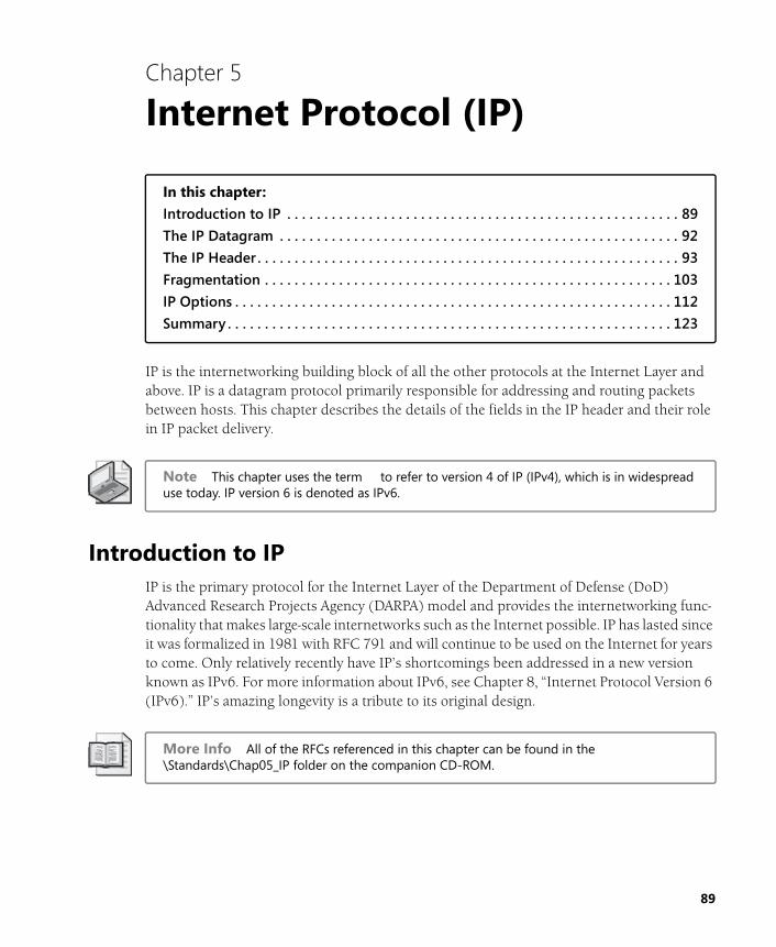
IP is the internetworking building block of all the other protocols at the Internet Layer and above. IP is a datagram protocol primarily responsible for addressing and routing packets between hosts. This chapter describes the details of the fields in the IP header and their role in IP packet delivery.
Note This chapter uses the term to refer to version 4 of IP (IPv4), which is in widespread use today. IP version 6 is denoted as IPv6.
Introduction to IPIP is the primary protocol for the Internet Layer of the Department of Defense (DoD) Advanced Research Projects Agency (DARPA) model and provides the internetworking func-tionality that makes large-scale internetworks such as the Internet possible. IP has lasted since it was formalized in 1981 with RFC 791 and will continue to be used on the Internet for years to come. Only relatively recently have IP’s shortcomings been addressed in a new version known as IPv6. For more information about IPv6, see Chapter 8, “Internet Protocol Version 6 (IPv6).” IP’s amazing longevity is a tribute to its original design.
More Info All of the RFCs referenced in this chapter can be found in the \Standards\Chap05_IP folder on the companion CD-ROM.
89
90 Part I: Internet Layer Protocols
IP Services
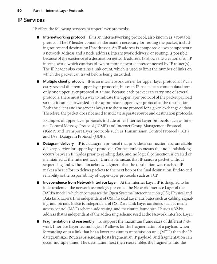
IP offers the following services to upper layer protocols:
■ Internetworking protocol IP is an internetworking protocol, also known as a routable protocol. The IP header contains information necessary for routing the packet, includ-ing source and destination IP addresses. An IP address is composed of two components: a network address and a node address. Internetwork delivery, or routing, is possible because of the existence of a destination network address. IP allows the creation of an IP internetwork, which consists of two or more networks interconnected by IP router(s). The IP header also contains a link count, which is used to limit the number of links on which the packet can travel before being discarded.
■ Multiple client protocols IP is an internetwork carrier for upper layer protocols. IP can carry several different upper layer protocols, but each IP packet can contain data from only one upper layer protocol at a time. Because each packet can carry one of several protocols, there must be a way to indicate the upper layer protocol of the packet payload so that it can be forwarded to the appropriate upper layer protocol at the destination. Both the client and the server always use the same protocol for a given exchange of data. Therefore, the packet does not need to indicate separate source and destination protocols.
Examples of upper-layer protocols include other Internet Layer protocols such as Inter-net Control Message Protocol (ICMP) and Internet Group Management Protocol (IGMP) and Transport Layer protocols such as Transmission Control Protocol (TCP) and User Datagram Protocol (UDP).
■ Datagram delivery IP is a datagram protocol that provides a connectionless, unreliable delivery service for upper layer protocols. Connectionless means that no handshaking occurs between IP nodes prior to sending data, and no logical connection is created or maintained at the Internet Layer. Unreliable means that IP sends a packet without sequencing and without an acknowledgment that the destination was reached. IP makes a best effort to deliver packets to the next hop or the final destination. End-to-end reliability is the responsibility of upper-layer protocols such as TCP.
■ Independence from Network Interface Layer At the Internet Layer, IP is designed to be independent of the network technology present at the Network Interface Layer of the DARPA model, which encompasses the Open Systems Interconnection (OSI) Physical and Data Link Layers. IP is independent of OSI Physical Layer attributes such as cabling, signal-ing, and bit rate. It also is independent of OSI Data Link Layer attributes such as media access control (MAC) scheme, addressing, and maximum frame size. IP uses a 32-bit address that is independent of the addressing scheme used at the Network Interface Layer.
■ Fragmentation and reassembly To support the maximum frame sizes of different Net-work Interface Layer technologies, IP allows for the fragmentation of a payload when forwarding onto a link that has a lower maximum transmission unit (MTU) than the IP datagram size. Routers or sending hosts fragment an IP payload, and fragmentation can occur multiple times. The destination host then reassembles the fragments into the
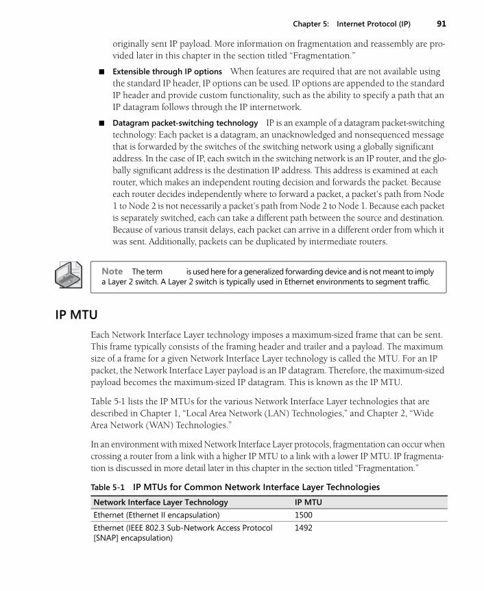
Chapter 5: Internet Protocol (IP) 91
originally sent IP payload. More information on fragmentation and reassembly are pro-vided later in this chapter in the section titled “Fragmentation.”
■ Extensible through IP options When features are required that are not available using the standard IP header, IP options can be used. IP options are appended to the standard IP header and provide custom functionality, such as the ability to specify a path that an IP datagram follows through the IP internetwork.
■ Datagram packet-switching technology IP is an example of a datagram packet-switching technology: Each packet is a datagram, an unacknowledged and nonsequenced message that is forwarded by the switches of the switching network using a globally significant address. In the case of IP, each switch in the switching network is an IP router, and the glo-bally significant address is the destination IP address. This address is examined at each router, which makes an independent routing decision and forwards the packet. Because each router decides independently where to forward a packet, a packet’s path from Node 1 to Node 2 is not necessarily a packet’s path from Node 2 to Node 1. Because each packet is separately switched, each can take a different path between the source and destination. Because of various transit delays, each packet can arrive in a different order from which it was sent. Additionally, packets can be duplicated by intermediate routers.
Note The term is used here for a generalized forwarding device and is not meant to imply a Layer 2 switch. A Layer 2 switch is typically used in Ethernet environments to segment traffic.
IP MTU
Each Network Interface Layer technology imposes a maximum-sized frame that can be sent. This frame typically consists of the framing header and trailer and a payload. The maximum size of a frame for a given Network Interface Layer technology is called the MTU. For an IP packet, the Network Interface Layer payload is an IP datagram. Therefore, the maximum-sized payload becomes the maximum-sized IP datagram. This is known as the IP MTU.
Table 5-1 lists the IP MTUs for the various Network Interface Layer technologies that are described in Chapter 1, “Local Area Network (LAN) Technologies,” and Chapter 2, “Wide Area Network (WAN) Technologies.”
In an environment with mixed Network Interface Layer protocols, fragmentation can occur when crossing a router from a link with a higher IP MTU to a link with a lower IP MTU. IP fragmenta-tion is discussed in more detail later in this chapter in the section titled “Fragmentation.”
Table 5-1 IP MTUs for Common Network Interface Layer Technologies
Network Interface Layer Technology IP MTU
Ethernet (Ethernet II encapsulation) 1500
Ethernet (IEEE 802.3 Sub-Network Access Protocol [SNAP] encapsulation)
1492

92 Part I: Internet Layer Protocols
In Windows Server 2008 and Windows Vista, it is possible to override the MTU as reported to the Network Driver Interface Specification (NDIS) interface by the network adapter driver with the following command:
netsh interface ipv4 set interface InterfaceNameOrIndex mtu=MtuSize
InterfaceNameOrIndex is the name of the interface from the Network Connections folder or its interface index. MtuSize is the IP MTU.
You can also use the following registry value:
MTUKey: HKEY_LOCAL_MACHINE\SYSTEM\CurrentControlSet\Services\Tcpip\
Parameters\Interfaces\InterfaceGUID
Data type: REG_DWORD
Valid range: 576 - <the MTU reported by the network adapter>
Default: 0xFFFFFFFF (the MTU reported by the network adapter)
Present by default: No
When TCP/IP initializes, it queries its bound NDIS network adapter driver and receives the MTU. The MTU registry value is used to set an MTU that is lower than the default MTU, as reported by the NDIS driver, and greater than the minimum value of 576. Values in the MTU registry value that are greater than the default MTU are ignored. If the MTU registry value is set to a value less than 576, 576 is used.
It is useful to change the default MTU size for testing or for solving MTU issues in transla-tional bridge environments.
The IP DatagramFigure 5-1 shows the structure of an IP datagram.
The IP datagram consists of the following:
■ IP header The IP header is of variable size, between 20 and 60 bytes, in 4-byte incre-ments. It provides routing support, payload identification, IP header and datagram size indication, fragmentation support, and options.
Token Ring (4 and 16 Mbps) Varies based on token holding time
Fiber Distributed Data Interface (FDDI) 4352
Frame relay 1592 (with a 2-byte Address field in the Frame Relay header)
Table 5-1 IP MTUs for Common Network Interface Layer Technologies
Network Interface Layer Technology IP MTU

Chapter 5: Internet Protocol (IP) 93
Figure 5-1 The structure of the IP datagram at the Network Interface layer
■ IP payload The IP payload is of variable size, ranging from 0 bytes (a 20-byte IP data-gram with a 20-byte IP header) to 65,515 bytes (a 65,535-byte IP datagram with a 20-byte header).
As sent on a link, the IP datagram is wrapped with a Network Interface Layer header and trailer to create a Network Interface Layer frame.
The IP HeaderFigure 5-2 shows the IP header’s structure. The following sections discuss the fields of the IP header.
Figure 5-2 The structure of the IP header
Version
The Version field is 4 bits long and is used to indicate the IP header version. A 4-bit field can have values from 0 through 15. The most prevalent IP version used today on organization intranets
NetworkInterfaceheader
IP header IP payloadNetworkInterface
trailer
IP datagram
Network Interface Layer frame
. . .
=4Version
Internet Header Length
Type of Service
Total Length
Identification
Flags
Fragment Offset
Time-to-Live
Protocol
Header Checksum
Source Address
Destination Address
Options and Padding
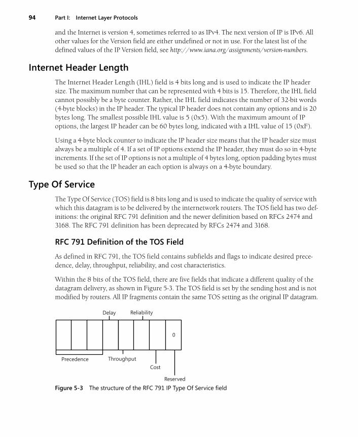
94 Part I: Internet Layer Protocols
and the Internet is version 4, sometimes referred to as IPv4. The next version of IP is IPv6. All other values for the Version field are either undefined or not in use. For the latest list of the defined values of the IP Version field, see http://www.iana.org/assignments/version-numbers.
Internet Header Length
The Internet Header Length (IHL) field is 4 bits long and is used to indicate the IP header size. The maximum number that can be represented with 4 bits is 15. Therefore, the IHL field cannot possibly be a byte counter. Rather, the IHL field indicates the number of 32-bit words (4-byte blocks) in the IP header. The typical IP header does not contain any options and is 20 bytes long. The smallest possible IHL value is 5 (0x5). With the maximum amount of IP options, the largest IP header can be 60 bytes long, indicated with a IHL value of 15 (0xF).
Using a 4-byte block counter to indicate the IP header size means that the IP header size must always be a multiple of 4. If a set of IP options extend the IP header, they must do so in 4-byte increments. If the set of IP options is not a multiple of 4 bytes long, option padding bytes must be used so that the IP header an each option is always on a 4-byte boundary.
Type Of Service
The Type Of Service (TOS) field is 8 bits long and is used to indicate the quality of service with which this datagram is to be delivered by the internetwork routers. The TOS field has two def-initions: the original RFC 791 definition and the newer definition based on RFCs 2474 and 3168. The RFC 791 definition has been deprecated by RFCs 2474 and 3168.
RFC 791 Definition of the TOS Field
As defined in RFC 791, the TOS field contains subfields and flags to indicate desired prece-dence, delay, throughput, reliability, and cost characteristics.
Within the 8 bits of the TOS field, there are five fields that indicate a different quality of the datagram delivery, as shown in Figure 5-3. The TOS field is set by the sending host and is not modified by routers. All IP fragments contain the same TOS setting as the original IP datagram.
Figure 5-3 The structure of the RFC 791 IP Type Of Service field
0
Precedence Throughput
Delay Reliability
Reserved
Cost
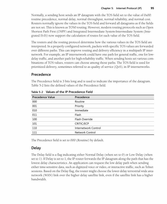
Chapter 5: Internet Protocol (IP) 95
Normally, a sending host sends an IP datagram with the TOS field set to the value of 0x00: routine precedence, normal delay, normal throughput, normal reliability, and normal cost. Routers normally ignore the values in the TOS field and forward all datagrams as if the fields are not set. This is known as TOS0 routing. However, modern routing protocols such as Open Shortest Path First (OSPF) and Integrated Intermediate System-Intermediate System (Inte-grated IS-IS) now support the calculation of routes for each value of the TOS field.
The routers and the routing protocol determine how the various values in the TOS field are interpreted. In a properly configured network, packets with specific TOS values are forwarded over different paths. This can improve routing and delivery efficiency in a multipath IP inter-network. For example, an IP internetwork could have one path for general traffic, one for low-delay traffic, and another path for high-reliability traffic. When sending hosts set various com-binations of TOS values, routers can choose among those paths. The TOS field is used for prioritized delivery, sometimes referred to as quality of service (QoS), in IP internetworks.
Precedence
The Precedence field is 3 bits long and is used to indicate the importance of the datagram. Table 5-2 lists the defined values of the Precedence field.
The Precedence field is set to 000 (Routine) by default.
Delay
The Delay field is a flag indicating either Normal Delay (when set to 0) or Low Delay (when set to 1). If Delay is set to 1, the IP router forwards the IP datagram along the path that has the lowest delay characteristics. An application can request the low delay path when sending either time-sensitive data, such as digitized voice or video, or interactive traffic, such as Telnet sessions. Based on the Delay flag, the router might choose the lower delay terrestrial wide area network (WAN) link over the higher delay satellite link, even if the satellite link has a higher bandwidth.
Table 5-2 Values of the IP Precedence Field
Precedence Value Precedence
000 Routine
001 Priority
010 Immediate
011 Flash
100 Flash Override
101 CRITIC/ECP
110 Internetwork Control
111 Network Control

96 Part I: Internet Layer Protocols
Throughput
The Throughput field is a flag indicating either Normal Throughput (when set to 0) or High Throughput (when set to 1). If the Throughput field is set to 1, the IP router forwards the IP datagram along the path that has the highest throughput characteristics. An application can request the high throughput path when sending bulk data. Based on the Throughput flag, the router can choose the higher throughput satellite link over the lower throughput terrestrial WAN link, even if the terrestrial link has a lower delay.
Reliability
The Reliability field is a flag indicating either Normal Reliability (when set to 0) or High Reli-ability (when set to 1). During periods of congestion at an IP router, the Reliability field is used to decide which IP datagrams to discard first. If the Reliability field is set to 1, the IP router discards these datagrams last. An application can request the high reliability path when send-ing time-sensitive data, so that it cannot be discarded. For example, with some methods of sending digital video, the digitized video is sent as two types of packets: The primary type is used to reconstruct the basic video image, and a secondary type is used to provide a higher resolution image. In this case, the primary packets are sent with the Reliability field set to 1 and the secondary packets are sent with the Reliability field set to 0. If congestion occurs at the router, the router discards the secondary packets first.
Cost
The Cost field is a flag indicating either Normal Cost (when set to 0) or Low Cost (when set to 1), where cost indicates monetary cost. If the Cost field is set to 1, the IP router forwards the IP datagram along the path that has the lowest cost characteristics. An application can request the low cost path when sending noncritical data. Based on the Cost flag, the router can choose a lower cost terrestrial link over a higher cost satellite link, even if the terrestrial link has a lower bandwidth.
Reserved
The Reserved field is the last bit and must be set to 0. Routers ignore this field when forward-ing IP datagrams.
RFC 2474 Definition of the TOS Field
To accommodate prioritized delivery of IP packets over an IP internetwork, RFC 2474 rede-fines the 8 bits in the TOS field in terms of a 6-bit Differentiated Services Code Point (DSCP) field and 2 unused bits. The DSCP value identifies the per-hop behavior that the receiving routers use to determine the special delivery handling for the packet. DSCP values are defined by network policy.
The RFC 2474–defined TOS field is shown in Figure 5-4.
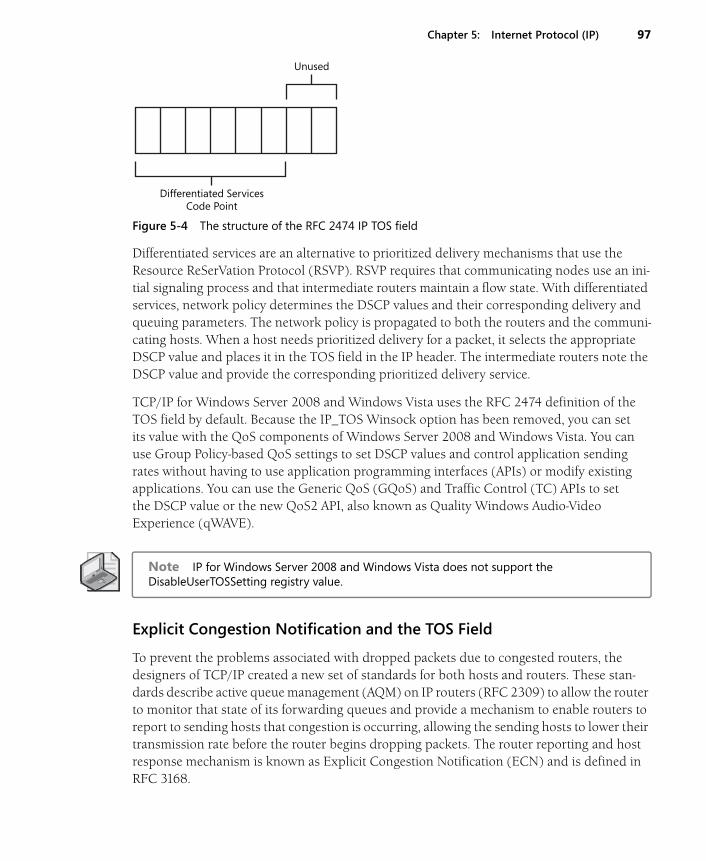
Chapter 5: Internet Protocol (IP) 97
Figure 5-4 The structure of the RFC 2474 IP TOS field
Differentiated services are an alternative to prioritized delivery mechanisms that use the Resource ReSerVation Protocol (RSVP). RSVP requires that communicating nodes use an ini-tial signaling process and that intermediate routers maintain a flow state. With differentiated services, network policy determines the DSCP values and their corresponding delivery and queuing parameters. The network policy is propagated to both the routers and the communi-cating hosts. When a host needs prioritized delivery for a packet, it selects the appropriate DSCP value and places it in the TOS field in the IP header. The intermediate routers note the DSCP value and provide the corresponding prioritized delivery service.
TCP/IP for Windows Server 2008 and Windows Vista uses the RFC 2474 definition of the TOS field by default. Because the IP_TOS Winsock option has been removed, you can set its value with the QoS components of Windows Server 2008 and Windows Vista. You can use Group Policy-based QoS settings to set DSCP values and control application sending rates without having to use application programming interfaces (APIs) or modify existing applications. You can use the Generic QoS (GQoS) and Traffic Control (TC) APIs to set the DSCP value or the new QoS2 API, also known as Quality Windows Audio-Video Experience (qWAVE).
Note IP for Windows Server 2008 and Windows Vista does not support the DisableUserTOSSetting registry value.
Explicit Congestion Notification and the TOS Field
To prevent the problems associated with dropped packets due to congested routers, the designers of TCP/IP created a new set of standards for both hosts and routers. These stan-dards describe active queue management (AQM) on IP routers (RFC 2309) to allow the router to monitor that state of its forwarding queues and provide a mechanism to enable routers to report to sending hosts that congestion is occurring, allowing the sending hosts to lower their transmission rate before the router begins dropping packets. The router reporting and host response mechanism is known as Explicit Congestion Notification (ECN) and is defined in RFC 3168.
Unused
Differentiated ServicesCode Point
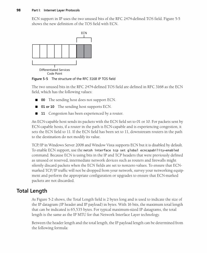
98 Part I: Internet Layer Protocols
ECN support in IP uses the two unused bits of the RFC 2474-defined TOS field. Figure 5-5 shows the new definition of the TOS field with ECN.
Figure 5-5 The structure of the RFC 3168 IP TOS field
The two unused bits in the RFC 2474-defined TOS field are defined in RFC 3168 as the ECN field, which has the following values:
■ 00 The sending host does not support ECN.
■ 01 or 10 The sending host supports ECN.
■ 11 Congestion has been experienced by a router.
An ECN-capable host sends its packets with the ECN field set to 01 or 10. For packets sent by ECN-capable hosts, if a router in the path is ECN-capable and is experiencing congestion, it sets the ECN field to 11. If the ECN field has been set to 11, downstream routers in the path to the destination do not modify its value.
TCP/IP in Windows Server 2008 and Window Vista supports ECN but it is disabled by default. To enable ECN support, use the netsh interface tcp set global ecncapability=enabled command. Because ECN is using bits in the IP and TCP headers that were previously defined as unused or reserved, intermediate network devices such as routers and firewalls might silently discard packets when the ECN fields are set to nonzero values. To ensure that ECN-marked TCP/IP traffic will not be dropped from your network, survey your networking equip-ment and perform the appropriate configuration or upgrades to ensure that ECN-marked packets are not discarded.
Total Length
As Figure 5-2 shows, the Total Length field is 2 bytes long and is used to indicate the size of the IP datagram (IP header and IP payload) in bytes. With 16 bits, the maximum total length that can be indicated is 65,535 bytes. For typical maximum-sized IP datagrams, the total length is the same as the IP MTU for that Network Interface Layer technology.
Between the header length and the total length, the IP payload length can be determined from the following formula:
ECN
Differentiated ServicesCode Point
Chapter 5: Internet Protocol (IP) 99
IP payload length (bytes) = Total Length value (bytes) – (4 × IHL value (32-bit words))
Identification
The Identification field is 2 bytes long and is used to identify a specific IP packet sent between a source and destination node. The sending host sets the field’s value, and the field is incre-mented for successive IP datagrams. The Identification field is used to identify the fragments of an original IP datagram.
Flags
The Flags field is 3 bits long and contains two flags for fragmentation. One flag is used to indi-cate whether the IP payload is eligible for fragmentation, and the other indicates whether or not there are more fragments to follow for this fragmented IP datagram.
More information on these flags and their uses can be found in the section titled “Fragmenta-tion,” later in this chapter.
Fragment Offset
The Fragment Offset field is 13 bits long and is used to indicate the offset of where this frag-ment begins relative to the original unfragmented IP payload.
More information on the Fragment Offset field can be found in the section titled “Fragmenta-tion,” later in this chapter.
Time-To-Live
The Time-To-Live (TTL) field is 1 byte long and is used to indicate how many links on which this IP datagram can travel before an IP router discards it. The TTL field was originally intended for use as a time counter, to indicate the number of seconds that the IP datagram could exist on the Internet. An IP router was intended to keep track of the time that it received the IP datagram and the time that it forwarded the IP datagram. The TTL was then decreased by the number of seconds that the packet resided at the router.
However, the latest modern standard (RFC 1812) specifies that IP routers decrement the TTL by 1 when forwarding an IP datagram. Therefore, the TTL is an inverse link count. The send-ing host sets the initial TTL, which acts as a maximum link count. The maximum value limits the number of links on which the datagram can travel and prevents a datagram from indefi-nitely looping.
Some additional aspects of the TTL field include the following:
■ Routers decrement the TTL in received packets to be routed before consulting the rout-ing table. If the TTL is less than 1, the packet is discarded and an ICMP Time Expired-TTL Expired In Transit message is sent back to the sending host.

100 Part I: Internet Layer Protocols
■ Unicast destination hosts do not check the TTL field.
■ Sending hosts must send IP datagrams with a TTL greater than 0. The exact value of the TTL for sent IP datagrams is either an operating system default or is specified by the application. The maximum value of the TTL is 255.
■ A recommended value of the TTL is twice the diameter of your internetwork. The diam-eter is the number of links between the farthest two nodes on the IP internetwork.
■ The TTL is independent of routing protocol metrics such as the Routing Information Protocol (RIP) hop count and the OSPF cost.
Note The TTL can be mistakenly referred to as a hop count when in fact it is a link count. The difference is subtle but important. The hop count is the number of routers to cross to reach a given destination. Link count is the number of Network Interface Layer links to cross to reach a given destination. The difference between hop count and link count is 1. For example, if Host A and Host B are separated by five routers, the hop count is 5, but the link count is 6. An IP datagram sent from Host A to Host B with a TTL of 5 is discarded by the fifth router. An IP datagram sent from Host A to Host B with a TTL of 6 will arrive at Host B.
The default TTL for Windows Server 2008 and Windows Vista is 128. You can change the default value of the TTL field for sent packets with the following command:
netsh interface ipv4 set global defaultcurhoplimit=TTL
You can also use the following registry value:
DefaultTTLKey: HKEY_LOCAL_MACHINE\SYSTEM\CurrentControlSet\Services\Tcpip\Parameters
Value type: REG_DWORD
Valid range: 0 - 255
Default: 128
Present by default: No
The default value of DefaultTTL is set to 128 so that IP packets sent by a Windows Server 2008 or Windows Vista–based computer can reach locations on the Internet that might need to traverse many links. Changing the value of DefaultTTL is necessary only when the diameter of your network changes. Windows Sockets applications can override this default value.
Setting the TTL with Ping
The Windows Server 2008 and Windows Vista Ping.exe tool with the -i option can be used to set the TTL value in ICMP Echo messages. The syntax is:
ping -i TTLValue Destination
For example, to ping 10.0.0.1 with a TTL field that is set to 7, use the following command:
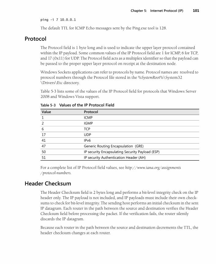
Chapter 5: Internet Protocol (IP) 101
ping -i 7 10.0.0.1
The default TTL for ICMP Echo messages sent by the Ping.exe tool is 128.
Protocol
The Protocol field is 1 byte long and is used to indicate the upper layer protocol contained within the IP payload. Some common values of the IP Protocol field are 1 for ICMP, 6 for TCP, and 17 (0x11) for UDP. The Protocol field acts as a multiplex identifier so that the payload can be passed to the proper upper layer protocol on receipt at the destination node.
Windows Sockets applications can refer to protocols by name. Protocol names are resolved to protocol numbers through the Protocol file stored in the %SystemRoot%\System32\Drivers\Etc directory.
Table 5-3 lists some of the values of the IP Protocol field for protocols that Windows Server 2008 and Windows Vista support.
For a complete list of IP Protocol field values, see http://www.iana.org/assignments/protocol-numbers.
Header Checksum
The Header Checksum field is 2 bytes long and performs a bit-level integrity check on the IP header only. The IP payload is not included, and IP payloads must include their own check-sums to check for bit-level integrity. The sending host performs an initial checksum in the sent IP datagram. Each router in the path between the source and destination verifies the Header Checksum field before processing the packet. If the verification fails, the router silently discards the IP datagram.
Because each router in the path between the source and destination decrements the TTL, the header checksum changes at each router.
Table 5-3 Values of the IP Protocol Field
Value Protocol
1 ICMP
2 IGMP
6 TCP
17 UDP
41 IPv6
47 Generic Routing Encapsulation (GRE)
50 IP security Encapsulating Security Payload (ESP)
51 IP security Authentication Header (AH)
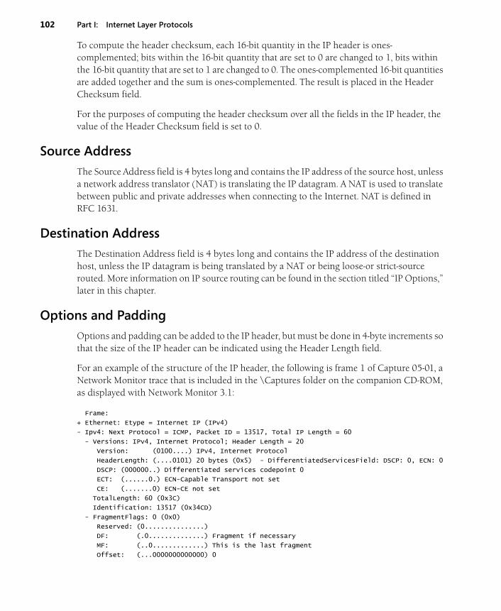
102 Part I: Internet Layer Protocols
To compute the header checksum, each 16-bit quantity in the IP header is ones-complemented; bits within the 16-bit quantity that are set to 0 are changed to 1, bits within the 16-bit quantity that are set to 1 are changed to 0. The ones-complemented 16-bit quantities are added together and the sum is ones-complemented. The result is placed in the Header Checksum field.
For the purposes of computing the header checksum over all the fields in the IP header, the value of the Header Checksum field is set to 0.
Source Address
The Source Address field is 4 bytes long and contains the IP address of the source host, unless a network address translator (NAT) is translating the IP datagram. A NAT is used to translate between public and private addresses when connecting to the Internet. NAT is defined in RFC 1631.
Destination Address
The Destination Address field is 4 bytes long and contains the IP address of the destination host, unless the IP datagram is being translated by a NAT or being loose-or strict-source routed. More information on IP source routing can be found in the section titled “IP Options,” later in this chapter.
Options and Padding
Options and padding can be added to the IP header, but must be done in 4-byte increments so that the size of the IP header can be indicated using the Header Length field.
For an example of the structure of the IP header, the following is frame 1 of Capture 05-01, a Network Monitor trace that is included in the \Captures folder on the companion CD-ROM, as displayed with Network Monitor 3.1:
Frame:
+ Ethernet: Etype = Internet IP (IPv4)
- Ipv4: Next Protocol = ICMP, Packet ID = 13517, Total IP Length = 60
- Versions: IPv4, Internet Protocol; Header Length = 20
Version: (0100....) IPv4, Internet Protocol
HeaderLength: (....0101) 20 bytes (0x5) - DifferentiatedServicesField: DSCP: 0, ECN: 0
DSCP: (000000..) Differentiated services codepoint 0
ECT: (......0.) ECN-Capable Transport not set
CE: (.......0) ECN-CE not set
TotalLength: 60 (0x3C)
Identification: 13517 (0x34CD)
- FragmentFlags: 0 (0x0)
Reserved: (0...............)
DF: (.0..............) Fragment if necessary
MF: (..0.............) This is the last fragment
Offset: (...0000000000000) 0
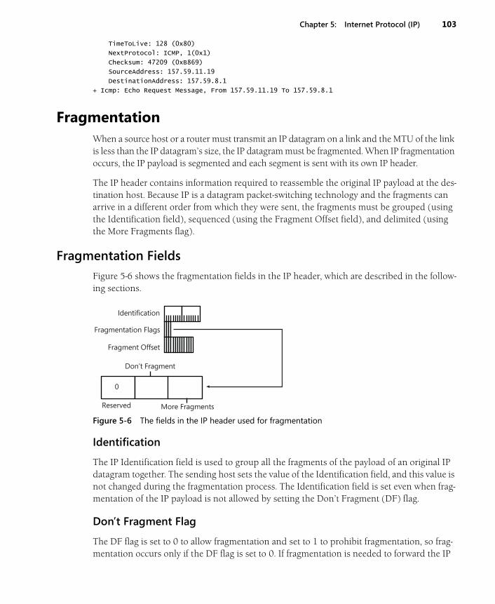
Chapter 5: Internet Protocol (IP) 103
TimeToLive: 128 (0x80)
NextProtocol: ICMP, 1(0x1)
Checksum: 47209 (0xB869)
SourceAddress: 157.59.11.19
DestinationAddress: 157.59.8.1
+ Icmp: Echo Request Message, From 157.59.11.19 To 157.59.8.1
FragmentationWhen a source host or a router must transmit an IP datagram on a link and the MTU of the link is less than the IP datagram’s size, the IP datagram must be fragmented. When IP fragmentation occurs, the IP payload is segmented and each segment is sent with its own IP header.
The IP header contains information required to reassemble the original IP payload at the des-tination host. Because IP is a datagram packet-switching technology and the fragments can arrive in a different order from which they were sent, the fragments must be grouped (using the Identification field), sequenced (using the Fragment Offset field), and delimited (using the More Fragments flag).
Fragmentation Fields
Figure 5-6 shows the fragmentation fields in the IP header, which are described in the follow-ing sections.
Figure 5-6 The fields in the IP header used for fragmentation
Identification
The IP Identification field is used to group all the fragments of the payload of an original IP datagram together. The sending host sets the value of the Identification field, and this value is not changed during the fragmentation process. The Identification field is set even when frag-mentation of the IP payload is not allowed by setting the Don’t Fragment (DF) flag.
Don’t Fragment Flag
The DF flag is set to 0 to allow fragmentation and set to 1 to prohibit fragmentation, so frag-mentation occurs only if the DF flag is set to 0. If fragmentation is needed to forward the IP
0
Don’t Fragment
More Fragments Reserved
Identification
Fragmentation Flags
Fragment Offset

104 Part I: Internet Layer Protocols
datagram and the DF flag is set to 1, the router should send an ICMP Destination Unreachable-Fragmentation Needed And DF Set message back to the source host and discards the IP datagram.
Fragmentation and reassembly is an expensive process at the routers and the destination host. The DF flag and the ICMP Destination Unreachable-Fragmentation Needed And DF Set message are the mechanisms by which a sending host discovers the MTU of the path between the source and the destination, or Path MTU Discovery. For more information, see Chapter 6, “Internet Control Message Protocol (ICMP).”
More Fragments Flag
The More Fragments (MF) flag is set to 0 if there are no more fragments that follow this fragment (this is the last fragment), and set to 1 if there are more fragments that follow this fragment (this is not the last fragment).
Fragment Offset
The Fragment Offset field is set to indicate the position of the fragment relative to the original IP payload. The Fragment Offset is an offset used for sequencing during reassembly, putting the incoming fragments in proper order to reconstruct the original payload. The Fragment Offset field is 13 bits long. With a maximum IP payload size of 65,515 bytes (the maximum IP MTU of 65,535 minus a minimum-sized IP header of 20 bytes), the Fragment Offset field can-not possibly indicate a byte offset. At 13 bits, the maximum value is 8191. The fragment offset must be 16 bits long to be a byte offset.
Because 16 bits are required to indicate a maximum-sized IP payload and only 13 bits are available in the Fragment Offset field, each value of the fragment offset must represent 3 bits. Therefore, the Fragment Offset field is defined in terms of 8-byte blocks, called fragment blocks.
During fragmentation, the payload is fragmented along 8-byte boundaries and the maximum number of 8-byte fragment blocks is placed in each fragment. The Fragment Offset field is set to indicate the starting fragment block for the fragment relative to the original IP payload.
For each fragment being fragmented by a router, the original IP header is copied and the following fields are changed:
■ Header Length Might or might not change depending on whether IP options are present and whether the options are copied to all fragments or just the first fragment. IP options are discussed in the section titled “IP Options,” later in this chapter.
■ TTL Decremented by 1.
■ Total Length Changed to reflect the new IP header and payload size.
■ MF Set to 1 for the first or middle fragments. Set to 0 for the last fragment.
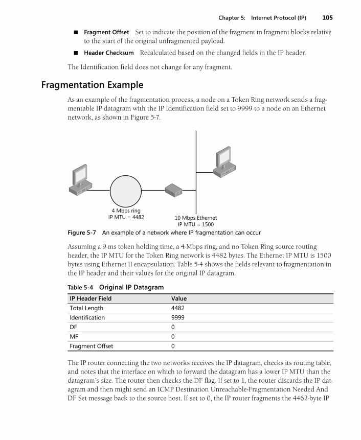
Chapter 5: Internet Protocol (IP) 105
■ Fragment Offset Set to indicate the position of the fragment in fragment blocks relative to the start of the original unfragmented payload.
■ Header Checksum Recalculated based on the changed fields in the IP header.
The Identification field does not change for any fragment.
Fragmentation Example
As an example of the fragmentation process, a node on a Token Ring network sends a frag-mentable IP datagram with the IP Identification field set to 9999 to a node on an Ethernet network, as shown in Figure 5-7.
Figure 5-7 An example of a network where IP fragmentation can occur
Assuming a 9-ms token holding time, a 4-Mbps ring, and no Token Ring source routing header, the IP MTU for the Token Ring network is 4482 bytes. The Ethernet IP MTU is 1500 bytes using Ethernet II encapsulation. Table 5-4 shows the fields relevant to fragmentation in the IP header and their values for the original IP datagram.
The IP router connecting the two networks receives the IP datagram, checks its routing table, and notes that the interface on which to forward the datagram has a lower IP MTU than the datagram’s size. The router then checks the DF flag. If set to 1, the router discards the IP dat-agram and then might send an ICMP Destination Unreachable-Fragmentation Needed And DF Set message back to the source host. If set to 0, the IP router fragments the 4462-byte IP
Table 5-4 Original IP Datagram
IP Header Field Value
Total Length 4482
Identification 9999
DF 0
MF 0
Fragment Offset 0
4 Mbps ring IP MTU = 4482 10 Mbps Ethernet
IP MTU = 1500
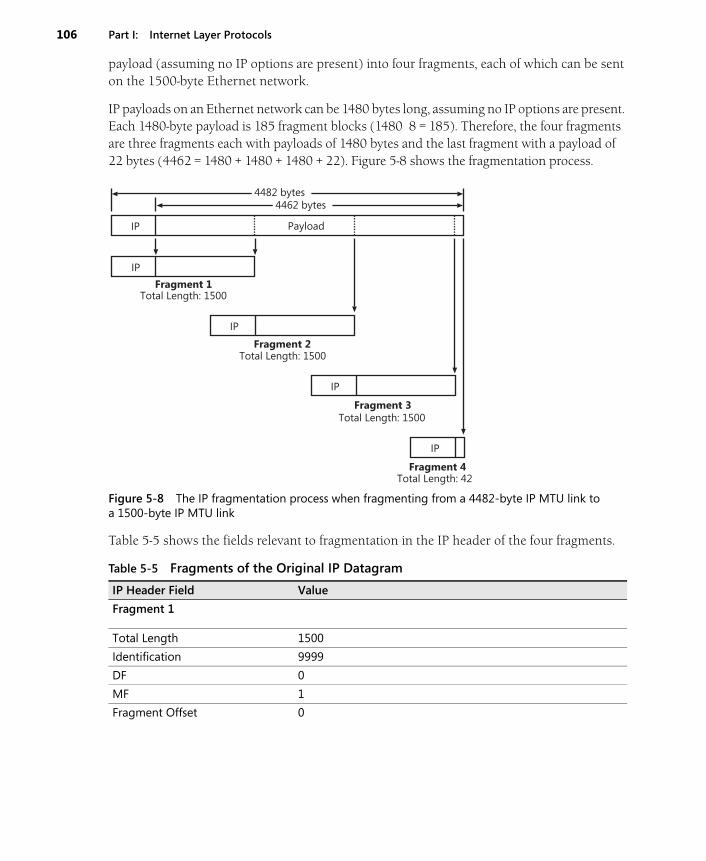
106 Part I: Internet Layer Protocols
payload (assuming no IP options are present) into four fragments, each of which can be sent on the 1500-byte Ethernet network.
IP payloads on an Ethernet network can be 1480 bytes long, assuming no IP options are present. Each 1480-byte payload is 185 fragment blocks (1480 8 = 185). Therefore, the four fragments are three fragments each with payloads of 1480 bytes and the last fragment with a payload of 22 bytes (4462 = 1480 + 1480 + 1480 + 22). Figure 5-8 shows the fragmentation process.
Figure 5-8 The IP fragmentation process when fragmenting from a 4482-byte IP MTU link to a 1500-byte IP MTU link
Table 5-5 shows the fields relevant to fragmentation in the IP header of the four fragments.
Table 5-5 Fragments of the Original IP Datagram
IP Header Field Value
Fragment 1
Total Length 1500
Identification 9999
DF 0
MF 1
Fragment Offset 0
Fragment 1
Fragment 2
Fragment 3
Fragment 4
Total Length: 1500
Total Length: 1500
Total Length: 1500
Total Length: 42
Payload
4462 bytes4482 bytes
IP
IP
IP
IP
IP
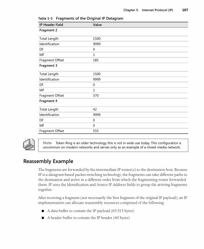
Chapter 5: Internet Protocol (IP) 107
Note Token Ring is an older technology this is not in wide use today. This configuration is uncommon on modern networks and serves only as an example of a mixed-media network.
Reassembly Example
The fragments are forwarded by the intermediate IP router(s) to the destination host. Because IP is a datagram-based packet-switching technology, the fragments can take different paths to the destination and arrive in a different order from which the fragmenting router forwarded them. IP uses the Identification and Source IP Address fields to group the arriving fragments together.
After receiving a fragment (not necessarily the first fragment of the original IP payload), an IP implementation can allocate reassembly resources comprised of the following:
■ A data buffer to contain the IP payload (65,515 bytes)
■ A header buffer to contain the IP header (60 bytes)
Fragment 2
Total Length 1500
Identification 9999
DF 0
MF 1
Fragment Offset 185
Fragment 3
Total Length 1500
Identification 9999
DF 0
MF 1
Fragment Offset 370
Fragment 4
Total Length 42
Identification 9999
DF 0
MF 0
Fragment Offset 555
Table 5-5 Fragments of the Original IP Datagram
IP Header Field Value
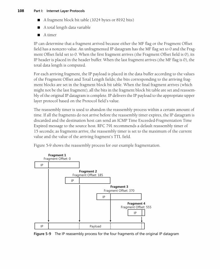
108 Part I: Internet Layer Protocols
■ A fragment block bit table (1024 bytes or 8192 bits)
■ A total length data variable
■ A timer
IP can determine that a fragment arrived because either the MF flag or the Fragment Offset field has a nonzero value. An unfragmented IP datagram has the MF flag set to 0 and the Frag-ment Offset field set to 0. When the first fragment arrives (the Fragment Offset field is 0), its IP header is placed in the header buffer. When the last fragment arrives (the MF flag is 0), the total data length is computed.
For each arriving fragment, the IP payload is placed in the data buffer according to the values of the Fragment Offset and Total Length fields; the bits corresponding to the arriving frag-ment blocks are set in the fragment block bit table. When the final fragment arrives (which might not be the last fragment), all the bits in the fragment block bit table are set and reassem-bly of the original IP datagram is complete. IP delivers the IP payload to the appropriate upper layer protocol based on the Protocol field’s value.
The reassembly timer is used to abandon the reassembly process within a certain amount of time. If all the fragments do not arrive before the reassembly timer expires, the IP datagram is discarded and the destination host can send an ICMP Time Exceeded-Fragmentation Time Expired message to the source host. RFC 791 recommends a default reassembly timer of 15 seconds; as fragments arrive, the reassembly timer is set to the maximum of the current value and the value of the arriving fragment’s TTL field.
Figure 5-9 shows the reassembly process for our example fragmentation.
Figure 5-9 The IP reassembly process for the four fragments of the original IP datagram
Fragment 1
Fragment 2
Fragment 3
Fragment 4
Fragment Offset: 0
Fragment Offset: 185
Fragment Offset: 370
Fragment Offset: 555
IP
IP
IP
IP
IP Payload
Chapter 5: Internet Protocol (IP) 109
Fragmenting a Fragment
It is possible for fragments to become further fragmented. In this case, each fragmented pay-load is fragmented to fit the MTU of the link onto which it is being forwarded. The process of fragmenting a fragmented payload is slightly different from fragmenting an original IP pay-load in how the MF flag is set.
When fragmenting a previously fragmented payload, the MF flag is always set to 1, except when the fragment of the fragmented payload is the last fragment of the original payload.
■ If an IP router fragments a previously fragmented first or middle fragment, all of the fragments have the MF flag set to 1.
■ If an IP router fragments a previously fragmented last fragment, all of the fragments except the last fragment have the MF flag set to 1.
Therefore, regardless of how many times the IP datagram is fragmented, only one fragment has the MF flag set to 0, indicating the last fragment of the original IP payload.
Network Monitor Capture 05-02 (in the \Captures folder on the companion CD-ROM) pro-vides an example of source-based IP fragmentation. The capture is the fragmentation of a 5008-byte ICMP Echo message so that it fits on an Ethernet network.
Avoiding Fragmentation
Although fragmentation allows IP nodes to communicate regardless of differing MTUs in intermediate subnets and without user intervention, IP fragmentation and reassembly is a rel-atively expensive process—both at the routers (or sending hosts) and at the destination host. On the modern Internet, fragmentation is highly discouraged; Internet routers are busy enough with the forwarding of IP traffic.
Fragmentation can be avoided by taking the following two measures:
■ Discover the IP MTU that is supported by all of the links in the path between the source and the destination (the path MTU).
■ Set the DF flag to 1 on all IP datagrams sent.
For more information on the Path MTU Discovery process, see Chapter 6, “Internet Control Message Protocol (ICMP).”
Setting the DF Flag with Ping
The Windows Server 2008 and Windows Vista Ping.exe tool with the -f option can be used to set the DF flag to 1 in ICMP Echo messages. The syntax is
ping –f Destination
110 Part I: Internet Layer Protocols
For example, to ping 10.0.0.1 and set the DF flag to 1, use the following command:
ping -f 10.0.0.1
By default, ICMP Echo messages sent by the Ping.exe tool have the DF flag set to 0 (fragmen-tation allowed).
Setting the IP Payload Size with Ping
The Windows Server 2008 and Windows Vista Ping.exe tool with the -l option can be used to send IP packets with an arbitrary size by specifying the size of the Optional Data field in an ICMP Echo message. The syntax is:
ping -l OptionalDataFieldSize Destination
OptionalDataFieldSize is the size of the Optional Data field in an ICMP Echo message in bytes.
For example, to ping 10.0.0.1 with an Optional Data field size of 5000, use the following command:
ping -l 5000 10.0.0.1
The default Optional Data field size for Ping is 32 bytes.
The Optional Data field size is not the same as the IP payload size because ICMP Echo mes-sages include an 8-byte ICMP header. Therefore, to calculate the IP payload’s size, add 8 to the Optional Data field size. To calculate the IP datagram’s size, add 20 to the size of the IP pay-load (or 28 to the size of the Optional Data field size). To ping with an ICMP Echo message at the maximum size allowed by the Network Interface technology, subtract 28 from the IP MTU. For example, to ping the address 10.0.0.1 with a maximum-sized ICMP Echo message on an Ethernet network (with an IP MTU of 1500), use the following Ping command:
ping -l 1472 10.0.0.1
Using Ping to Do Source Fragmentation
The Windows Server 2008 and Windows Vista Ping.exe tool with the -l option can be used to do source fragmentation. Pinging with an Optional Data field size that is greater than (IP MTU – 28) bytes produces source-fragmented packets. For example, pinging from an Ether-net node with an Optional Data field size of 1472 or less does not produce fragmented pack-ets. Pinging from an Ethernet node with an Optional Data field size greater than 1472 does produce fragmented packets.
Fragmentation and Translational Bridging Environments
Translational bridging is the interconnection of two different Network Interface Layer technol-ogies on the same network by a Layer 2 device such as a bridge or switch. Translational
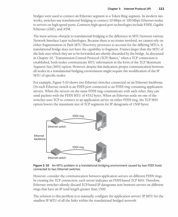
Chapter 5: Internet Protocol (IP) 111
bridges were used to connect an Ethernet segment to a Token Ring segment. In modern net-works, switches use translational bridging to connect 10-Mbps or 100-Mbps Ethernet nodes to servers on high-speed ports. Common high-speed port technologies include FDDI, Gigabit Ethernet (GbE), and ATM.
The most serious obstacle to translational bridging is the difference in MTU between various Network Interface Layer technologies. Because there is no router involved, we cannot rely on either fragmentation or Path MTU Discovery processes to account for the differing MTUs. A translational bridge does not have the capability to fragment. Frames larger than the MTU of the link onto which they are to be forwarded are silently discarded by the bridge. As discussed in Chapter 10, “Transmission Control Protocol (TCP) Basics,” when a TCP connection is established, both nodes communicate MTU information in the form of the TCP Maximum Segment Size (MSS) option. However, despite this indication, proper communication between all nodes in a translational bridging environment might require the modification of the IP MTU of specific nodes.
For example, Figure 5-10 shows two Ethernet switches connected on an Ethernet backbone. On each Ethernet switch is an FDDI port connected to an FDDI ring containing application servers. When the servers on the same FDDI ring communicate with each other, they can send packets with the FDDI MTU of 4352 bytes. When an Ethernet node on one of the switches uses TCP to connect to an application server on either FDDI ring, the TCP MSS option lowers the maximum size of TCP segments for IP datagrams of 1500 bytes.
Figure 5-10 An MTU problem in a translational bridging environment caused by two FDDI hosts connected to two Ethernet switches
However, consider the communication between application servers on different FDDI rings. In creating the TCP connection, each server indicates an FDDI-based TCP MSS. Therefore, Ethernet switches silently discard TCP-based IP datagrams sent between servers on different rings that have an IP total length greater than 1500.
The solution to this problem is to manually configure the application servers’ IP MTU for the smallest IP MTU of all the links within the translational bridged network.
FDDI ring
Ethernet switch
FDDI ring
Ethernet switch
Ethernet backbone
112 Part I: Internet Layer Protocols
Using our example, the IP MTU of the application servers on the FDDI rings are set to 1500, so translational bridges can forward IP datagrams between FDDI rings. Changing the applica-tion servers’ MTU means that when sending packets to application servers on the same ring, the packets are sent at the lower MTU of 1500, a lower efficiency than the default FDDI MTU of 4352. However, it is better to have lower efficiency between servers on the same ring than zero efficiency between servers on different rings. For nodes running Windows Server 2008 or Windows Vista, use the netsh interface ipv4 set interface InterfaceNameOrIndex mtu= MtuSize command or the MTU registry value to override the default MTU setting reported by NDIS.
Note FDDI is an older technology whose use has been made obsolete by 100 Mbps Ether-net. This configuration is unlikely on modern networks and serves only as an example of a mixed-media subnet.
Fragmentation and TCP/IP for Windows Server 2008 and Windows Vista
TCP/IP for Windows Server 2008 and Windows Vista supports IP fragmentation and reas-sembly with the following additional behaviors:
■ IP can handle irregular fragments, which overlap either fully or partially, with already received fragments for the same payload.
■ When forwarding fragments, IP can forward the individual fragments separately or hold all of the fragments and then send all of them when the last one arrives. The default behavior is to forward individual fragments. You can change this behavior with the netsh interface ipv4 set global groupforwardedfragments=enabled command.
■ The maximum amount of memory that can be allocated for reassembly for all incoming IP packets is controlled by the netsh interface ipv4 set global reassemblylimit=MemorySize command. You can view the current size of the reassembly buffer with the netsh interface ipv4 show global command.
IP OptionsIP options are additional fields appended to the standard 20-byte IP header. Although IP options are not required on each IP header, the ability to process IP option fields is required. IP options are used infrequently and mostly for network testing purposes.
The IP options portion size of the IP header varies in length based on the IP options that are being used. The individual IP options also vary in length from a single byte to multiple four-byte quantities. Recall that the maximum-sized IP header that can be indicated with the Header Length field is 60 bytes. With a standard IP header size of 20 bytes, 40 bytes are left for IP options.
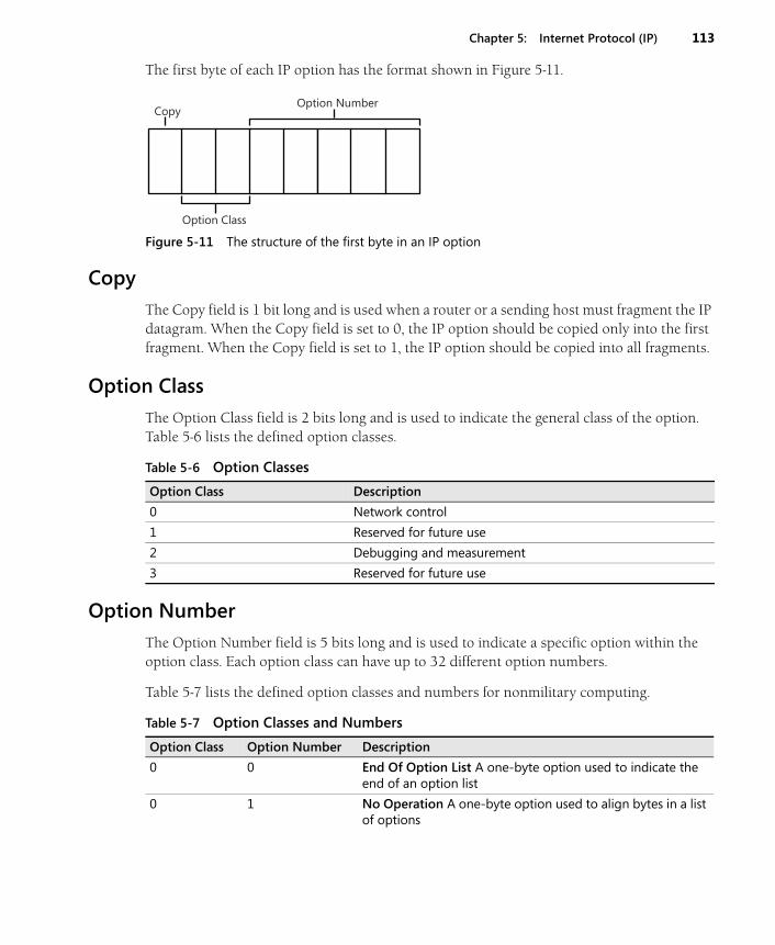
Chapter 5: Internet Protocol (IP) 113
The first byte of each IP option has the format shown in Figure 5-11.
Figure 5-11 The structure of the first byte in an IP option
Copy
The Copy field is 1 bit long and is used when a router or a sending host must fragment the IP datagram. When the Copy field is set to 0, the IP option should be copied only into the first fragment. When the Copy field is set to 1, the IP option should be copied into all fragments.
Option Class
The Option Class field is 2 bits long and is used to indicate the general class of the option. Table 5-6 lists the defined option classes.
Option Number
The Option Number field is 5 bits long and is used to indicate a specific option within the option class. Each option class can have up to 32 different option numbers.
Table 5-7 lists the defined option classes and numbers for nonmilitary computing.
Option Class
CopyOption Number
Table 5-6 Option Classes
Option Class Description
0 Network control
1 Reserved for future use
2 Debugging and measurement
3 Reserved for future use
Table 5-7 Option Classes and Numbers
Option Class Option Number Description
0 0 End Of Option List A one-byte option used to indicate the end of an option list
0 1 No Operation A one-byte option used to align bytes in a list of options
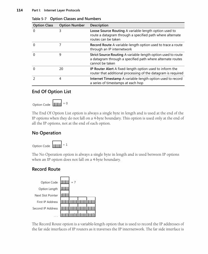
114 Part I: Internet Layer Protocols
End Of Option List
The End Of Option List option is always a single byte in length and is used at the end of the IP options when they do not fall on a 4-byte boundary. This option is used only at the end of all the IP options, not at the end of each option.
No Operation
The No Operation option is always a single byte in length and is used between IP options when an IP option does not fall on a 4-byte boundary.
Record Route
The Record Route option is a variable-length option that is used to record the IP addresses of the far side interfaces of IP routers as it traverses the IP internetwork. The far side interface is
0 3 Loose Source Routing A variable-length option used to route a datagram through a specified path where alternate routes can be taken
0 7 Record Route A variable-length option used to trace a route through an IP internetwork
0 9 Strict Source Routing A variable-length option used to route a datagram through a specified path where alternate routes cannot be taken
0 20 IP Router Alert A fixed-length option used to inform the router that additional processing of the datagram is required
2 4 Internet Timestamp A variable-length option used to record a series of timestamps at each hop
Table 5-7 Option Classes and Numbers
Option Class Option Number Description
Option Code = 0
Option Code = 1
Option Code
Option Length
Next Slot Pointer
First IP Address
Second IP Address
. . .
= 7
Chapter 5: Internet Protocol (IP) 115
the interface on the router on which the IP datagram is forwarded, presumed to be farthest from the sending host.
As the IP datagram is forwarded from router to router, each router adds its IP address to the list; each router also modifies the Next Slot Pointer field. The route from the source host to the destination host is recorded. To get the complete route, there must be enough room in the Record Route option. Unlike Token Ring source routing, the number of IP address slots is specified by the sending host and is fixed in the IP header.
The Record Route option contains the following fields:
■ Option Code Set to 7 (Copy Bit=0, Option Class=0, Option Number=7).
■ Option Length Set by the sending host to the number of bytes in the Record Route option.
■ Next Slot Pointer Set to the byte offset (starting at 1) within the Record Route option of the next available IP address. The minimum value of the Next Slot Pointer field is 4.
■ First IP Address, Second IP Address Set to the IP address of the far side interface by rout-ers. With a maximum of 40 bytes in the IP options portion of the IP header, there is enough room for a maximum of nine IP addresses.
Record Route Processing
An IP router receiving an IP datagram with the Record Route option compares the Option Length and Next Slot Pointer fields. If the Next Slot Pointer field is less than the Option Length field, there are open IP address fields. The router records the IP address of the inter-face that is forwarding the datagram in the next available IP address field; the router also updates the Next Slot Pointer field by adding 4. If the value of the Next Slot Pointer field is greater than the Option Length field, routers have used all of the available IP address fields. The router then forwards the IP datagram without modifying the Record Route option.
Because the Record Route option size is not a multiple of 4 bytes, either an End Of Options option (if there are no more options) or a No Operation option (if there are more options) must be added to ensure that the IP header is an integral multiple of 4 bytes.
Setting the Record Route Option with Ping
The Windows Server 2008 and Windows Vista Ping.exe tool with the -r option can be used to add the Record Route option and set the number of IP address slots in the Record Route option within an ICMP Echo message. The syntax is:
ping -r IPAddressSlots Destination
For example, to ping 10.0.0.1 with seven IP address slots, use the following command:
ping -r 7 10.0.0.1

116 Part I: Internet Layer Protocols
When both hosts are computers running Windows Server 2008 or Windows Vista, the Record Route option records the IP addresses of the far side interfaces of forwarding routers in the ICMP Echo message. When the Echo message is received, the IP addresses recorded are maintained and the Echo Reply message is sent with the same Record Route option. The Echo Reply message contains the recorded route for the Echo message and the recorded route for the Echo Reply message.
Therefore, with the Ping -r option, it is possible to record the far side router interfaces for the Echo message (the path from Host A to Host B) and the far side router interfaces for the Echo Reply message (the path from Host B to Host A). However, because there is only room for nine IP address slots, this is possible only if there are no more than four routers between hosts.
Network Monitor Capture 05-03 (in the \Captures folder on the companion CD-ROM) provides an example of Ping.exe tool traffic and the use of the Record Route option.
Note The Tracert.exe tool does not use the Record Route option.
Strict and Loose Source Routing
The IP routing process at IP routers is performed through a comparison of the destination IP address with entries in a local routing table. Each router makes a forwarding decision. How-ever, it is sometimes necessary to specify a path that an IP datagram is to take regardless of the router’s routing table entries. The path is specified before the source host sends the datagram; this is known as source routing.
For example, in a multipath IP internetwork (where there is more than one path between IP networks), routers choose the best path based on a lowest cost metric. Once a router deter-mines all of the best paths, the higher cost paths are not used unless the topology of the internetwork changes. To check that higher cost paths contain valid links, you must do source routing.
Source routing in IP is done by specifying the IP addresses of the near side interfaces of the desired routers between the source and its destination. At each leg of the journey, the destina-tion IP address in the IP header is set to the IP address of the next near side router interface. IP supports both loose and strict source routing. In loose source routing, the next router’s IP address does not have to be a neighboring router; it can be multiple hops away. In strict source routing, the next router’s IP address must be a neighboring router (a single hop away).
IP source routing also records the path taken in the same way as the Record Route option. For each intermediate destination, the IP address of the interface on the router that forwarded the IP datagram is recorded.
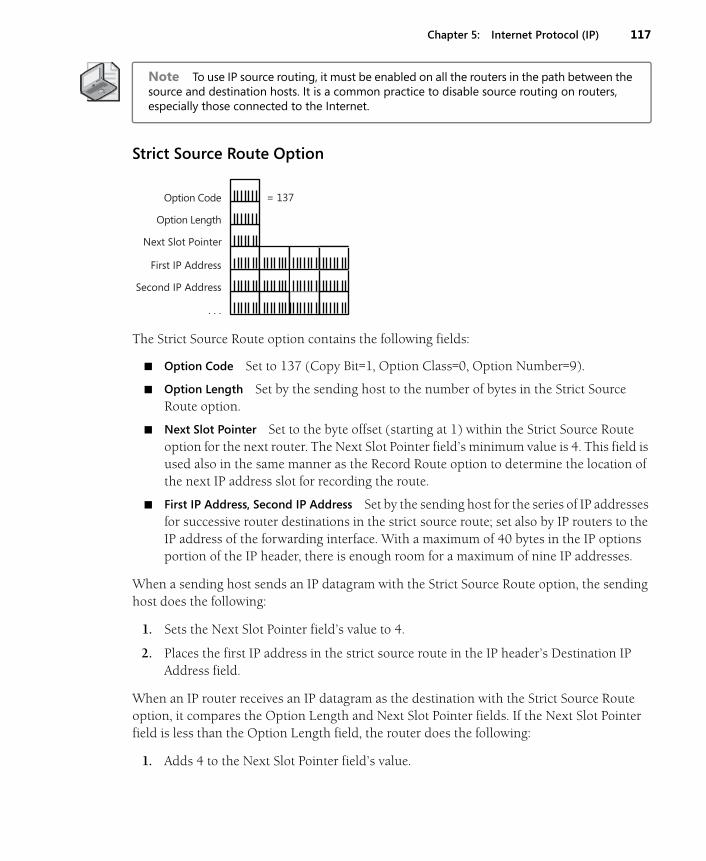
Chapter 5: Internet Protocol (IP) 117
Note To use IP source routing, it must be enabled on all the routers in the path between the source and destination hosts. It is a common practice to disable source routing on routers, especially those connected to the Internet.
Strict Source Route Option
The Strict Source Route option contains the following fields:
■ Option Code Set to 137 (Copy Bit=1, Option Class=0, Option Number=9).
■ Option Length Set by the sending host to the number of bytes in the Strict Source Route option.
■ Next Slot Pointer Set to the byte offset (starting at 1) within the Strict Source Route option for the next router. The Next Slot Pointer field’s minimum value is 4. This field is used also in the same manner as the Record Route option to determine the location of the next IP address slot for recording the route.
■ First IP Address, Second IP Address Set by the sending host for the series of IP addresses for successive router destinations in the strict source route; set also by IP routers to the IP address of the forwarding interface. With a maximum of 40 bytes in the IP options portion of the IP header, there is enough room for a maximum of nine IP addresses.
When a sending host sends an IP datagram with the Strict Source Route option, the sending host does the following:
1. Sets the Next Slot Pointer field’s value to 4.
2. Places the first IP address in the strict source route in the IP header’s Destination IP Address field.
When an IP router receives an IP datagram as the destination with the Strict Source Route option, it compares the Option Length and Next Slot Pointer fields. If the Next Slot Pointer field is less than the Option Length field, the router does the following:
1. Adds 4 to the Next Slot Pointer field’s value.
Option Code
Option Length
Next Slot Pointer
First IP Address
Second IP Address
. . .
= 137

118 Part I: Internet Layer Protocols
2. Replaces the IP header’s destination IP address with the IP address that is recorded in the next slot (based on the Next Slot Pointer field’s new value).
3. Records the IP address of the forwarding interface in the previous slot.
If the next destination IP address is not reachable using a directly attached network (the IP address of a neighboring router or host), the IP datagram is discarded and an ICMP Destina-tion Unreachable-Source Route Failed message is sent back to the source host.
If the Next Slot Pointer field’s value is greater than the Option Length field’s value, the IP datagram has reached its final destination.
Because the size of the Strict Source Route option is not a multiple of 4 bytes, either an End Of Options option (if there are no more options) or a No Operation option (if there are more options after the Strict Source Route option) must be added to ensure that the IP header is an integral multiple of 4 bytes. In Windows Server 2008 and Windows Vista, TCP/IP places the Strict Source Route option as the last option in the list and uses an End Of Options option to specify the end of the list of options.
Setting the Strict Source Route Option with Ping
The Windows Server 2008 and Windows Vista Ping.exe tool with the -k option can be used to add the Strict Source Route option. The Ping.exe tool with the –k option also can be used to set the IP addresses of successive routers and the final destination in ICMP Echo messages. The syntax is:
ping -k FirstHopIPAddress SecondHopIPAddress … Destination
For example, to ping 10.0.0.1 through neighboring router interfaces 192.168.1.1 and 192.168.2.1, use the following command:
ping -k 192.168.1.1 192.168.2.1 10.0.0.1
Network Monitor Capture 05-04 (in the \Captures folder on the companion CD-ROM) provides an example of Ping.exe tool traffic and the use of the Strict Source Route option.
Loose Source Route Option
Option Code
Option Length
Next Slot Pointer
First IP Address
Second IP Address
. . .
= 131
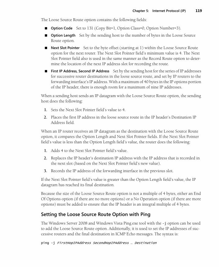
Chapter 5: Internet Protocol (IP) 119
The Loose Source Route option contains the following fields:
■ Option Code Set to 131 (Copy Bit=1, Option Class=0, Option Number=3).
■ Option Length Set by the sending host to the number of bytes in the Loose Source Route option.
■ Next Slot Pointer Set to the byte offset (starting at 1) within the Loose Source Route option for the next router. The Next Slot Pointer field’s minimum value is 4. The Next Slot Pointer field also is used in the same manner as the Record Route option to deter-mine the location of the next IP address slot for recording the route.
■ First IP Address, Second IP Address Set by the sending host for the series of IP addresses for successive router destinations in the loose source route, and set by IP routers to the forwarding interface’s IP address. With a maximum of 40 bytes in the IP options portion of the IP header, there is enough room for a maximum of nine IP addresses.
When a sending host sends an IP datagram with the Loose Source Route option, the sending host does the following:
1. Sets the Next Slot Pointer field’s value to 4.
2. Places the first IP address in the loose source route in the IP header’s Destination IP Address field.
When an IP router receives an IP datagram as the destination with the Loose Source Route option, it compares the Option Length and Next Slot Pointer fields. If the Next Slot Pointer field’s value is less than the Option Length field’s value, the router does the following:
1. Adds 4 to the Next Slot Pointer field’s value.
2. Replaces the IP header’s destination IP address with the IP address that is recorded in the next slot (based on the Next Slot Pointer field’s new value).
3. Records the IP address of the forwarding interface in the previous slot.
If the Next Slot Pointer field’s value is greater than the Option Length field’s value, the IP datagram has reached its final destination.
Because the size of the Loose Source Route option is not a multiple of 4 bytes, either an End Of Options option (if there are no more options) or a No Operation option (if there are more options) must be added to ensure that the IP header is an integral multiple of 4 bytes.
Setting the Loose Source Route Option with Ping
The Windows Server 2008 and Windows Vista Ping.exe tool with the -j option can be used to add the Loose Source Route option. Additionally, it is used to set the IP addresses of suc-cessive routers and the final destination in ICMP Echo messages. The syntax is:
ping -j FirstHopIPAddress SecondHopIPAddress … Destination
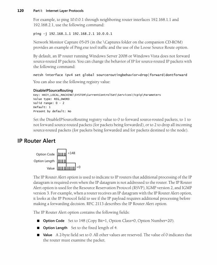
120 Part I: Internet Layer Protocols
For example, to ping 10.0.0.1 through neighboring router interfaces 192.168.1.1 and 192.168.2.1, use the following command:
ping -j 192.168.1.1 192.168.2.1 10.0.0.1
Network Monitor Capture 05-05 (in the \Captures folder on the companion CD-ROM) provides an example of Ping.exe tool traffic and the use of the Loose Source Route option.
By default, an IP router running Windows Server 2008 or Windows Vista does not forward source-routed IP packets. You can change the behavior of IP for source-routed IP packets with the following command:
netsh interface ipv4 set global sourceroutingbehavior=drop|forward|dontforward
You can also use the following registry value:
DisableIPSourceRoutingKey: HKEY_LOCAL_MACHINE\SYSTEM\CurrentControlSet\Services\Tcpip\Parameters
Value type: REG_DWORD
Valid range: 0 - 2
Default: 1
Present by default: No
Set the DisableIPSourceRouting registry value to 0 to forward source-routed packets, to 1 to not forward source-routed packets (for packets being forwarded), or to 2 to drop all incoming source-routed packets (for packets being forwarded and for packets destined to the node).
IP Router Alert
The IP Router Alert option is used to indicate to IP routers that additional processing of the IP datagram is required even when the IP datagram is not addressed to the router. The IP Router Alert option is used for the Resource Reservation Protocol (RSVP), IGMP version 2, and IGMP version 3. For example, when a router receives an IP datagram with the IP Router Alert option, it looks at the IP Protocol field to see if the IP payload requires additional processing before making a forwarding decision. RFC 2113 describes the IP Router Alert option.
The IP Router Alert option contains the following fields:
■ Option Code Set to 148 (Copy Bit=1, Option Class=0, Option Number=20).
■ Option Length Set to the fixed length of 4.
■ Value A 2-byte field set to 0. All other values are reserved. The value of 0 indicates that the router must examine the packet.
Option Code
Option Length
Value
=148
=0
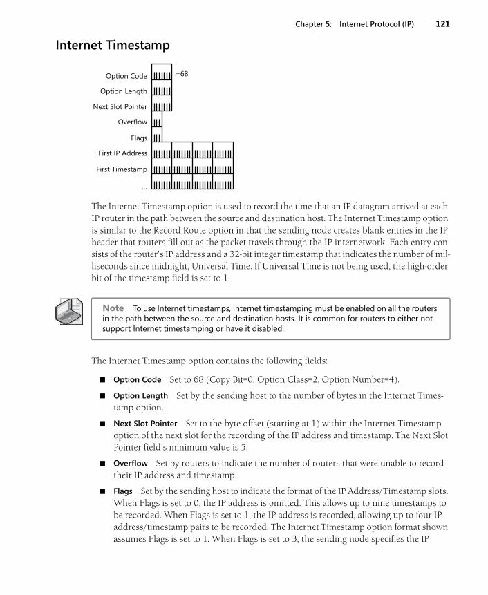
Chapter 5: Internet Protocol (IP) 121
Internet Timestamp
The Internet Timestamp option is used to record the time that an IP datagram arrived at each IP router in the path between the source and destination host. The Internet Timestamp option is similar to the Record Route option in that the sending node creates blank entries in the IP header that routers fill out as the packet travels through the IP internetwork. Each entry con-sists of the router’s IP address and a 32-bit integer timestamp that indicates the number of mil-liseconds since midnight, Universal Time. If Universal Time is not being used, the high-order bit of the timestamp field is set to 1.
Note To use Internet timestamps, Internet timestamping must be enabled on all the routers in the path between the source and destination hosts. It is common for routers to either not support Internet timestamping or have it disabled.
The Internet Timestamp option contains the following fields:
■ Option Code Set to 68 (Copy Bit=0, Option Class=2, Option Number=4).
■ Option Length Set by the sending host to the number of bytes in the Internet Times-tamp option.
■ Next Slot Pointer Set to the byte offset (starting at 1) within the Internet Timestamp option of the next slot for the recording of the IP address and timestamp. The Next Slot Pointer field’s minimum value is 5.
■ Overflow Set by routers to indicate the number of routers that were unable to record their IP address and timestamp.
■ Flags Set by the sending host to indicate the format of the IP Address/Timestamp slots. When Flags is set to 0, the IP address is omitted. This allows up to nine timestamps to be recorded. When Flags is set to 1, the IP address is recorded, allowing up to four IP address/timestamp pairs to be recorded. The Internet Timestamp option format shown assumes Flags is set to 1. When Flags is set to 3, the sending node specifies the IP
Option Code
Option Length
Next Slot Pointer
Overflow
Flags
First IP Address
First Timestamp
...
=68
122 Part I: Internet Layer Protocols
addresses of successive routers: A timestamp is recorded only if the IP address in the slot matches the router’s IP address.
■ First IP Address/First Timestamp Set by routers to record the IP address and timestamp of the routers encountered (when Flags is set to 1) or specified (when Flags is set to 3).
When a sending host sends an IP datagram with the Internet Timestamp option, the sending host does the following:
1. Sets the Next Slot Pointer field’s value to 5.
2. For a specified route (when Flags is set to 3), places the series of IP addresses in the Internet Timestamp option.
When an IP router receives an IP datagram with the Internet Timestamp option, it compares the Option Length and Next Slot Pointer fields. If the Next Slot Pointer field’s value is less than the Option Length field’s value, it does the following:
■ If Flags is set to 3, the router replaces the IP header’s destination IP address with the IP address that is recorded in the next slot (based on the Next Slot Pointer field).
■ If Flags is set to 1 or 3, the router records the IP address of the interface on which the IP datagram was received in the same slot.
■ If Flags is set to 0, the router records the timestamp and adds 4 to the Next Slot Pointer field. If Flags is set to 1, the router records the timestamp after the IP address and adds 8 to the Next Slot Pointer field. If Flags is set to 3, the router replaces the IP address and adds 4 to the Next Slot Pointer field.
If the Next Slot Pointer field’s value is greater than the Option Length field’s value, the router increments the Overflow field. If the Overflow field is 15 before incrementing, an ICMP Parameter Problem is sent back to the source host.
Setting the Internet Timestamp Option with Ping
The Windows Server 2008 and Windows Vista Ping.exe tool and the -s option can be used to send ICMP Echo messages with the Internet timestamp. The syntax is the following:
ping -s Slots Destination
For example, to ping the IP address of 10.9.1.1 using Internet timestamps with three slots, use the following command:
ping -s 3 10.9.1.1
Network Monitor Capture 05-06 (in the \Captures folder on the companion CD-ROM) provides an example of Ping.exe tool traffic and the use of the Internet Timestamp option.
Chapter 5: Internet Protocol (IP) 123
SummaryIP provides the internetworking building block for all other Internet Layer and higher proto-cols in the TCP/IP suite. IP provides a best effort, unreliable, connectionless datagram delivery service between networks of an IP internetwork. The IP header provides addressing, type of delivery, maximum link count, fragmentation, and checksum services. IP fragmentation pro-vides a way for IP datagrams to travel over links with a lower IP MTU than the original IP dat-agram. The basic services of the IP header are extended through IP options, the most common of which provide source routing, path recording, router alert, and timestamping functions.

Chapter 10
Transmission Control Protocol (TCP) Basics
In this chapter:
Introduction to TCP . . . . . . . . . . . . . . . . . . . . . . . . . . . . . . . . . . . . . . . . . . . . . . . . . . . 199
The TCP Segment. . . . . . . . . . . . . . . . . . . . . . . . . . . . . . . . . . . . . . . . . . . . . . . . . . . . . 200
The TCP Header . . . . . . . . . . . . . . . . . . . . . . . . . . . . . . . . . . . . . . . . . . . . . . . . . . . . . . 201
TCP Ports . . . . . . . . . . . . . . . . . . . . . . . . . . . . . . . . . . . . . . . . . . . . . . . . . . . . . . . . . . . . 204
TCP Flags . . . . . . . . . . . . . . . . . . . . . . . . . . . . . . . . . . . . . . . . . . . . . . . . . . . . . . . . . . . . 205
The TCP Pseudo Header . . . . . . . . . . . . . . . . . . . . . . . . . . . . . . . . . . . . . . . . . . . . . . . 207
TCP Urgent Data . . . . . . . . . . . . . . . . . . . . . . . . . . . . . . . . . . . . . . . . . . . . . . . . . . . . . 208
TCP Options . . . . . . . . . . . . . . . . . . . . . . . . . . . . . . . . . . . . . . . . . . . . . . . . . . . . . . . . . 210
Summary . . . . . . . . . . . . . . . . . . . . . . . . . . . . . . . . . . . . . . . . . . . . . . . . . . . . . . . . . . . . 221
There are two protocols at the Transport Layer that TCP/IP applications typically use for trans-porting data: Transmission Control Protocol (TCP) and User Datagram Protocol (UDP). This chapter describes the characteristics of TCP and the fields in the TCP header.
Introduction to TCPTCP, defined in RFC 793, is the Transport Layer protocol that provides a reliable data-transfer service and a method to pass TCP-encapsulated data to an Application Layer protocol. TCP has the following characteristics:
■ Connection-oriented Before data can be transferred, two Application Layer processes must formally negotiate a TCP connection using the TCP connection establishment process. TCP connections are formally closed using the TCP connection termination process. For more information about TCP connection processes, see Chapter 11, “Transmission Control Protocol (TCP) Connections.”
■ Full duplex For each TCP peer, the TCP connection consists of two logical pipes: an outgoing pipe and an incoming pipe. With the appropriate Network Interface Layer technology, data can be flowing out of the outgoing pipe and into the incoming pipe simultaneously. The TCP header contains both the sequence number of the outgoing data and an acknowledgment of the incoming data.
199
200 Part III: Transport Layer Protocols
■ Reliable Data sent on a TCP connection is sequenced and a positive acknowledgment is expected from the receiver. If no acknowledgment is received, the segment is retrans-mitted. At the receiver, duplicate segments are discarded and segments arriving out of sequence are placed back in the proper sequence. A TCP checksum is always used to verify the bit-level integrity of the TCP segment.
■ Byte stream TCP views the data sent over the incoming and outgoing logical pipes as a continuous stream of bytes. The sequence number and acknowledgment number in each TCP header are defined along byte boundaries. TCP is not aware of record or mes-sage boundaries within the byte stream. The Application Layer protocol must provide the proper parsing of the incoming byte stream.
■ Sender- and receiver-side flow control To avoid sending too much data at one time and congesting the routers of the network, TCP implements sender-side flow control that gradually scales the amount of data sent at one time. To avoid having the sender send data that the receiver cannot buffer, TCP implements receiver-side flow control that indi-cates the number of bytes that the receiver can receive. For more information on how TCP implements sender- and receiver-side flow control, see Chapter 12, “Transmission Control Protocol (TCP) Data Flow.”
■ Segmentation of Application Layer data TCP segments data obtained from the Applica-tion Layer process so that it will fit within an IP datagram sent on the Network Interface Layer link. TCP peers inform each other of the maximum-sized segment that they can receive and adjust the maximum size using Path Maximum Transmission Unit (PMTU) discovery.
■ One-to-one delivery TCP connections are a logical point-to-point circuit between two Application Layer protocols. TCP does not provide a one-to-many delivery service.
TCP is typically used when an Application Layer protocol requires a reliable data transfer service.
More Info All of the RFCs referenced in this chapter can be found in the \Standards\Chap10_TCP folder on the companion CD-ROM.
The TCP SegmentA TCP segment, consisting of a TCP header and its optional payload (a segment), is identified in the IP header with IP Protocol number 6. The segment can be a maximum size of 65,495 bytes: 65,535 minus the minimum-size IP header (20 bytes) and the minimum-size TCP header (20 bytes). The resulting IP datagram is then encapsulated with the appropriate Network Interface Layer header and trailer. Figure 10-1 displays the resulting frame.
In the IP header of TCP segments, the Source Address field indicates the unicast address of the host interface that sent the TCP segment. The Destination Address field indicates the uni-cast address of the destination host (or intermediate router if the packet is source routed).

Chapter 10: Transmission Control Protocol (TCP) Basics 201
Figure 10-1 TCP segment encapsulation showing the IP header and Network Interface Layer header and trailer
The TCP HeaderThe TCP header is of variable length, consisting of the fields shown in Figure 10-2. When TCP options are not present, the TCP header is 20 bytes long.
Figure 10-2 The structure of the TCP header
The fields in the TCP header are defined as follows:
■ Source Port A 2-byte field that indicates the source Application Layer protocol sending the TCP segment. The combination of the source IP address in the IP header and the source port in the TCP header indicates a source socket—a unique, globally significant address from which the segment was sent.
■ Destination Port A 2-byte field that indicates the destination Application Layer proto-col. The combination of the destination IP address in the IP header and the destination port in the TCP header indicates a destination socket—a unique, globally significant address to which the segment is sent.
NetworkInterfaceheader
NetworkInterface
trailerSegment
IP datagram
TCP segment
IP headerTCP
header
Network Interface Layer frame
Source Port
Destination Port
Sequence Number
Acknowledgment Number
Data Offset
Reserved
Flags
Window
Checksum
Urgent Pointer
Options and Padding . . .
202 Part III: Transport Layer Protocols
■ Sequence Number A 4-byte field that indicates the outgoing byte-stream-based sequence number of the segment’s first byte. The Sequence Number field is always set, even when there is no data in the segment. In this case, the Sequence Number field is set to the number of the outgoing byte stream’s next byte. When establishing a TCP connec-tion, TCP segments with a SYN (Synchronization) flag value of 1 set the Sequence Num-ber field to the Initial Sequence Number (ISN). This indicates that the first byte in the outgoing byte stream sent on the connection is ISN + 1.
■ Acknowledgment Number A 4-byte field that indicates the sequence number of the next byte in the incoming byte stream that the receiver of the incoming byte stream expects to receive. The acknowledgment number provides a positive acknowledgment that all bytes in the incoming byte stream up to, but not including, the acknowledgment number were received. The acknowledgment number is significant in all TCP segments with the ACK (Acknowledgment) flag set.
■ Data Offset A 4-bit field that indicates where the TCP segment data begins. The Data Offset field is also the TCP header’s size. Just as in the IP header’s Header Length field, the Data Offset field is the number of 32-bit words (4-byte blocks) in the TCP header. For the smallest TCP header (no options), the Data Offset field is set to 5 (0x5), indicat-ing that the segment data begins in the twentieth byte offset starting from the beginning of the TCP segment (the offset starts its count at 0). With a Data Offset field set to its maximum value of 15 (0xF), the largest TCP header, including TCP options, can be 60 bytes long.
■ Reserved A 4-bit field that is reserved for future use. The sender sets these bits to 0.
■ Flags An 8-bit field that indicates the eight TCP flags defined in RFCs 793 and 3168. The eight TCP flags, known as CWR (Congestion Window Reduced), ECE (Explicit Congestion Notification [ECN]-Echo), URG (Urgent), ACK, PSH (Push), RST (Reset), SYN, and FIN (Finish), are discussed in greater detail in the “TCP Flags” section of this chapter.
■ Window A 2-byte field that indicates the number of bytes that the receiver of the incoming byte stream allows the other TCP peer to send. By advertising the window size with each segment, a TCP receiver is telling the sender how much data can be sent and successfully received and stored. The sender should not be sending more data than the receiver can receive. If the receiver cannot receive any more data, it advertises a window size of 0 bytes. With a window size of 0, the sender cannot send any more data until the window size is a nonzero value. The advertisement of the window size is an implemen-tation of receiver-side flow control. The use of this field is extended to larger window sizes with the TCP Window Scale option, discussed in the “TCP Options” section of this chapter.
■ Checksum A 2-byte field that provides a bit-level integrity check for the TCP segment (TCP header and segment). The Checksum field’s value is calculated in the same way as
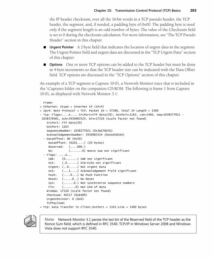
Chapter 10: Transmission Control Protocol (TCP) Basics 203
the IP header checksum, over all the 16-bit words in a TCP pseudo header, the TCP header, the segment, and, if needed, a padding byte of 0x00. The padding byte is used only if the segment length is an odd number of bytes. The value of the Checksum field is set to 0 during the checksum calculation. For more information, see “The TCP Pseudo Header” section in this chapter.
■ Urgent Pointer A 2-byte field that indicates the location of urgent data in the segment. The Urgent Pointer field and urgent data are discussed in the “TCP Urgent Data” section of this chapter.
■ Options One or more TCP options can be added to the TCP header but must be done in 4-byte increments so that the TCP header size can be indicated with the Data Offset field. TCP options are discussed in the “TCP Options” section of this chapter.
An example of a TCP segment is Capture 10-01, a Network Monitor trace that is included in the \Captures folder on the companion CD-ROM. The following is frame 1 from Capture 10-01, as displayed with Network Monitor 3.1:
Frame:
+ Ethernet: Etype = Internet IP (IPv4)
+ Ipv4: Next Protocol = TCP, Packet ID = 57288, Total IP Length = 1500
- Tcp: Flags=....A..., SrcPort=FTP data(20), DstPort=1163, Len=1460, Seq=1038577021 -
1038578481, Ack=3930983524, Win=17520 (scale factor not found)
SrcPort: FTP data(20)
DstPort: 1163
SequenceNumber: 1038577021 (0x3DE76D7D)
AcknowledgementNumber: 3930983524 (0xEA4E0C64)
- DataOffset: 80 (0x50)
DataOffset: (0101....) (20 bytes)
Reserved: (....000.)
NS: (.......0) Nonce Sum not significant
- Flags: ....A...
CWR: (0.......) CWR not significant
ECE: (.0......) ECN-Echo not significant
Urgent: (..0.....) Not Urgent Data
Ack: (...1....) Acknowledgement field significant
Push: (....0...) No Push Function
Reset: (.....0..) No Reset
Syn: (......0.) Not Synchronize sequence numbers
Fin: (.......0) Not End of data
Window: 17520 (scale factor not found)
Checksum: 46217 (0xB489)
UrgentPointer: 0 (0x0)
TCPPayload:
+ Ftp: Data Transfer To Client,DstPort = 1163,size = 1460 bytes
Note Network Monitor 3.1 parses the last bit of the Reserved field of the TCP header as the Nonce Sum field, which is defined in RFC 3540. TCP/IP in Windows Server 2008 and Windows Vista does not support RFC 3540.
204 Part III: Transport Layer Protocols
TCP PortsA TCP port defines a location for the delivery of TCP connection data. Included in each TCP segment is the source port that indicates the Application Layer process from which the seg-ment was sent, and a destination port that indicates the Application Layer process to which the segment was sent. There are port numbers that are assigned by the Internet Assigned Numbers Authority (IANA) to specific Application Layer protocols.
Table 10-1 shows assigned TCP port numbers used by components of Windows Server 2008 and Windows Vista.
See http://www.iana.org/assignments/port-numbers for the most current list of IANA-assigned TCP port numbers.
Typically, the server side of an Application Layer protocol listens on the well-known port num-ber. The client side of an Application Layer protocol uses either the well-known port number or, more commonly, a dynamically allocated port number. These dynamically allocated port numbers are used for the duration of the process and are known also as ephemeral or short-lived ports.
A Windows Sockets application using the GetServByName() function can refer to a TCP port number by name. The name is resolved to a TCP port number through the Services file stored in the %SystemRoot%\System32\Drivers\Etc folder.
A sending node determines the destination port (using either a specified value or the GetServByName() function) and the source port (using either a specified value, or by obtain-ing a dynamically allocated port through Windows Sockets). The sending node then passes the source IP address, destination IP address, source port, destination port, and the data to be sent to TCP/IP. The TCP component segments the data as needed. The TCP component
Table 10-1 Well-Known TCP Port Numbers
Port Number Application Layer Protocol
20 FTP Server (data channel)
21 FTP Server (control channel)
23 Telnet Server
25 Simple Mail Transfer Protocol (SMTP)
69 Trivial File Transfer Protocol (TFTP)
80 Hypertext Transfer Protocol (HTTP; Web server)
139 NetBIOS Session Service
443 HTTP protocol over Transport Layer Security (TLS)
445 Direct-Hosted Server Message Block (SMB) (also known as Microsoft-DS)
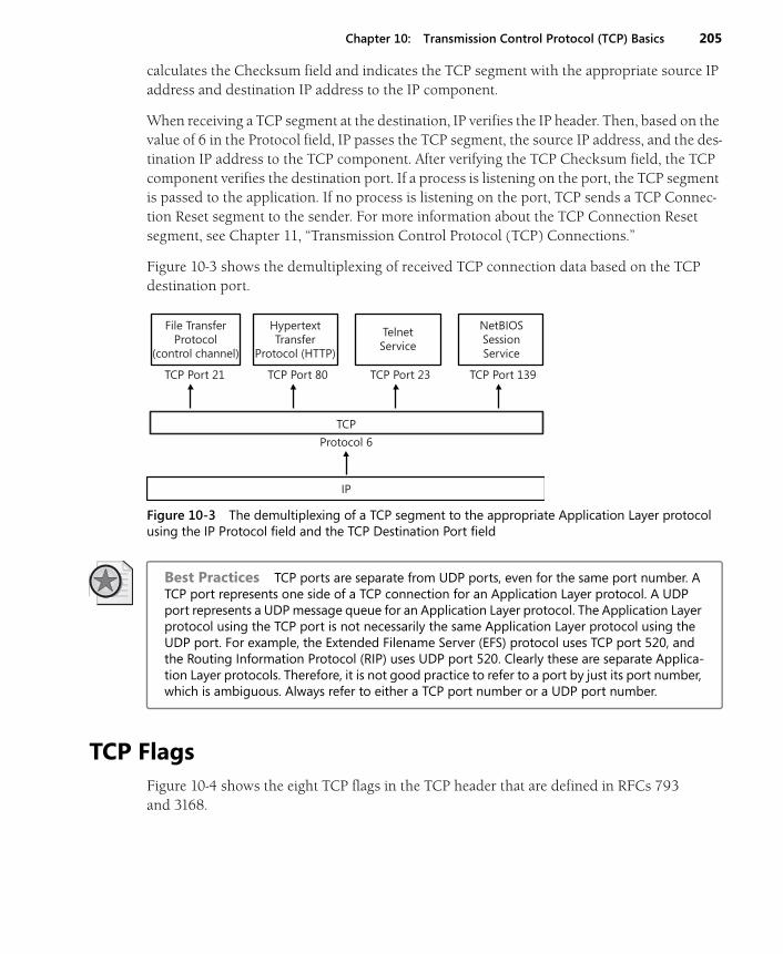
Chapter 10: Transmission Control Protocol (TCP) Basics 205
calculates the Checksum field and indicates the TCP segment with the appropriate source IP address and destination IP address to the IP component.
When receiving a TCP segment at the destination, IP verifies the IP header. Then, based on the value of 6 in the Protocol field, IP passes the TCP segment, the source IP address, and the des-tination IP address to the TCP component. After verifying the TCP Checksum field, the TCP component verifies the destination port. If a process is listening on the port, the TCP segment is passed to the application. If no process is listening on the port, TCP sends a TCP Connec-tion Reset segment to the sender. For more information about the TCP Connection Reset segment, see Chapter 11, “Transmission Control Protocol (TCP) Connections.”
Figure 10-3 shows the demultiplexing of received TCP connection data based on the TCP destination port.
Figure 10-3 The demultiplexing of a TCP segment to the appropriate Application Layer protocol using the IP Protocol field and the TCP Destination Port field
Best Practices TCP ports are separate from UDP ports, even for the same port number. A TCP port represents one side of a TCP connection for an Application Layer protocol. A UDP port represents a UDP message queue for an Application Layer protocol. The Application Layer protocol using the TCP port is not necessarily the same Application Layer protocol using the UDP port. For example, the Extended Filename Server (EFS) protocol uses TCP port 520, and the Routing Information Protocol (RIP) uses UDP port 520. Clearly these are separate Applica-tion Layer protocols. Therefore, it is not good practice to refer to a port by just its port number, which is ambiguous. Always refer to either a TCP port number or a UDP port number.
TCP FlagsFigure 10-4 shows the eight TCP flags in the TCP header that are defined in RFCs 793 and 3168.
File TransferProtocol
(control channel)
TelnetService
TCP Port 21 TCP Port 80 TCP Port 23 TCP Port 139
Protocol 6
IP
TCP
NetBIOSSessionService
HypertextTransfer
Protocol (HTTP)
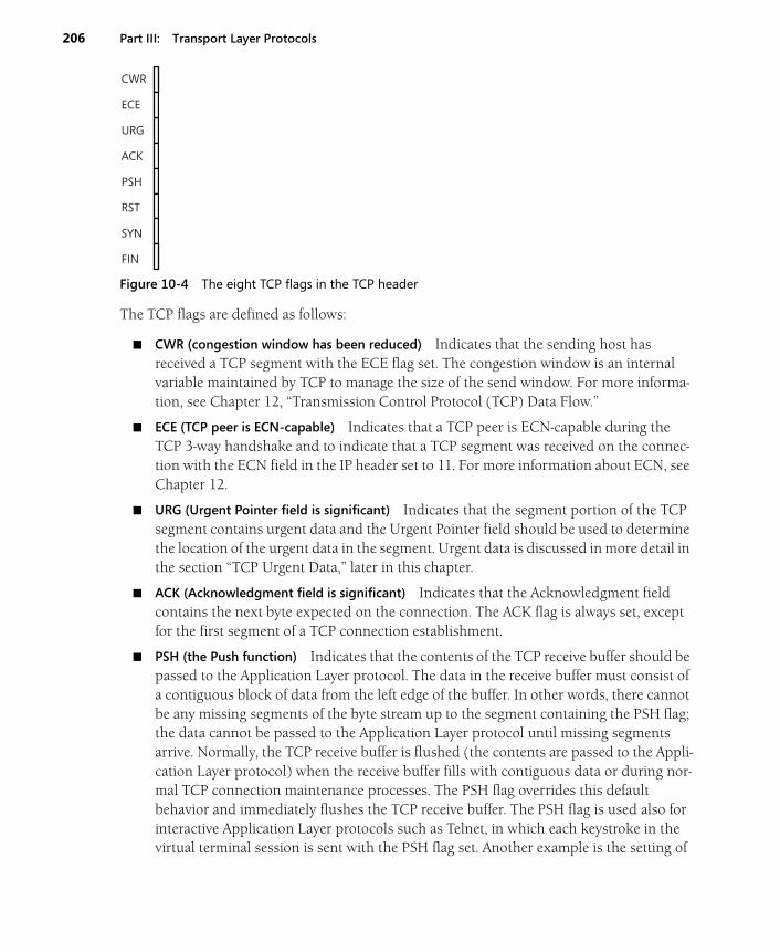
206 Part III: Transport Layer Protocols
Figure 10-4 The eight TCP flags in the TCP header
The TCP flags are defined as follows:
■ CWR (congestion window has been reduced) Indicates that the sending host has received a TCP segment with the ECE flag set. The congestion window is an internal variable maintained by TCP to manage the size of the send window. For more informa-tion, see Chapter 12, “Transmission Control Protocol (TCP) Data Flow.”
■ ECE (TCP peer is ECN-capable) Indicates that a TCP peer is ECN-capable during the TCP 3-way handshake and to indicate that a TCP segment was received on the connec-tion with the ECN field in the IP header set to 11. For more information about ECN, see Chapter 12.
■ URG (Urgent Pointer field is significant) Indicates that the segment portion of the TCP segment contains urgent data and the Urgent Pointer field should be used to determine the location of the urgent data in the segment. Urgent data is discussed in more detail in the section “TCP Urgent Data,” later in this chapter.
■ ACK (Acknowledgment field is significant) Indicates that the Acknowledgment field contains the next byte expected on the connection. The ACK flag is always set, except for the first segment of a TCP connection establishment.
■ PSH (the Push function) Indicates that the contents of the TCP receive buffer should be passed to the Application Layer protocol. The data in the receive buffer must consist of a contiguous block of data from the left edge of the buffer. In other words, there cannot be any missing segments of the byte stream up to the segment containing the PSH flag; the data cannot be passed to the Application Layer protocol until missing segments arrive. Normally, the TCP receive buffer is flushed (the contents are passed to the Appli-cation Layer protocol) when the receive buffer fills with contiguous data or during nor-mal TCP connection maintenance processes. The PSH flag overrides this default behavior and immediately flushes the TCP receive buffer. The PSH flag is used also for interactive Application Layer protocols such as Telnet, in which each keystroke in the virtual terminal session is sent with the PSH flag set. Another example is the setting of
CWR
ECE
URG
ACK
PSH
RST
SYN
FIN

Chapter 10: Transmission Control Protocol (TCP) Basics 207
the PSH flag on the last segment of a file transferred with FTP. Data sent with the PSH flag does not have to be immediately acknowledged.
■ RST (Reset the connection) Indicates that the connection is being aborted. For active connections, a node sends a TCP segment with the RST flag in response to a TCP seg-ment received on the connection that is incorrect, causing the connection to fail. The sending of an RST segment for an active connection forcibly terminates the connection, causing data stored in send and receive buffers or in transit to be lost. For TCP connec-tions being established, a node sends an RST segment in response to a connection establishment request to deny the connection attempt.
■ SYN (Synchronize sequence number) Indicates that the segment contains an ISN. Dur-ing the TCP connection establishment process, TCP sends a TCP segment with the SYN flag set. Each TCP peer acknowledges the receipt of the SYN flag by treating the SYN flag as if it were a single byte of data. The Acknowledgment Number field for the acknowl-edgment of the SYN segment is set to ISN + 1.
■ FIN (Finish sending data) Indicates that the TCP segment sender is finished sending data on the connection. When a TCP connection is gracefully terminated, each TCP peer sends a TCP segment with the FIN flag set. A TCP peer does not send a TCP segment with the FIN flag set until all outstanding data to the other TCP peer has been sent and acknowledged. Each peer acknowledges receipt of the FIN flag by treating it as if it were a single byte of data. When both TCP peers have sent segments with the FIN flag set and received acknowledgment of their receipt, the TCP connection is terminated.
The TCP Pseudo HeaderThe TCP pseudo header is used to associate the TCP segment with the IP header. The TCP pseudo header is added to the beginning of the TCP segment only during the checksum cal-culation and is not sent as part of the TCP segment. The use of the TCP pseudo header assures the receiver that a routing or fragmentation process did not improperly modify key fields in the IP header.
Figure 10-5 illustrates the TCP pseudo header.
Figure 10-5 The structure of the TCP pseudo header
= 0
= 6
Source IP Address
Destination IP Address
Unused
Protocol
Length
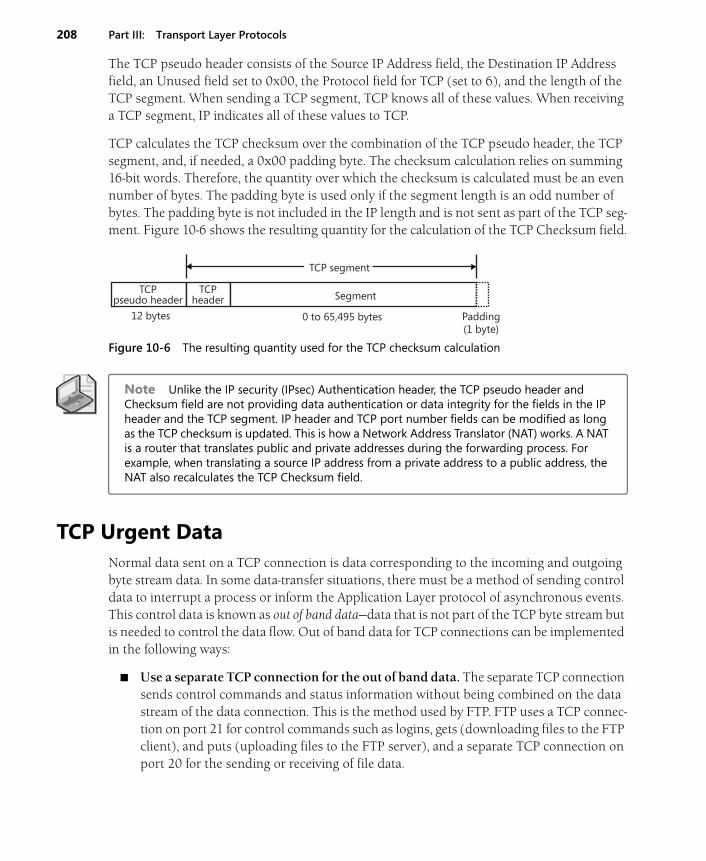
208 Part III: Transport Layer Protocols
The TCP pseudo header consists of the Source IP Address field, the Destination IP Address field, an Unused field set to 0x00, the Protocol field for TCP (set to 6), and the length of the TCP segment. When sending a TCP segment, TCP knows all of these values. When receiving a TCP segment, IP indicates all of these values to TCP.
TCP calculates the TCP checksum over the combination of the TCP pseudo header, the TCP segment, and, if needed, a 0x00 padding byte. The checksum calculation relies on summing 16-bit words. Therefore, the quantity over which the checksum is calculated must be an even number of bytes. The padding byte is used only if the segment length is an odd number of bytes. The padding byte is not included in the IP length and is not sent as part of the TCP seg-ment. Figure 10-6 shows the resulting quantity for the calculation of the TCP Checksum field.
Figure 10-6 The resulting quantity used for the TCP checksum calculation
Note Unlike the IP security (IPsec) Authentication header, the TCP pseudo header and Checksum field are not providing data authentication or data integrity for the fields in the IP header and the TCP segment. IP header and TCP port number fields can be modified as long as the TCP checksum is updated. This is how a Network Address Translator (NAT) works. A NAT is a router that translates public and private addresses during the forwarding process. For example, when translating a source IP address from a private address to a public address, the NAT also recalculates the TCP Checksum field.
TCP Urgent DataNormal data sent on a TCP connection is data corresponding to the incoming and outgoing byte stream data. In some data-transfer situations, there must be a method of sending control data to interrupt a process or inform the Application Layer protocol of asynchronous events. This control data is known as out of band data—data that is not part of the TCP byte stream but is needed to control the data flow. Out of band data for TCP connections can be implemented in the following ways:
■ Use a separate TCP connection for the out of band data. The separate TCP connection sends control commands and status information without being combined on the data stream of the data connection. This is the method used by FTP. FTP uses a TCP connec-tion on port 21 for control commands such as logins, gets (downloading files to the FTP client), and puts (uploading files to the FTP server), and a separate TCP connection on port 20 for the sending or receiving of file data.
TCP segment
0 to 65,495 bytes
Segment
12 bytes
TCP pseudo header
TCP header
Padding(1 byte)
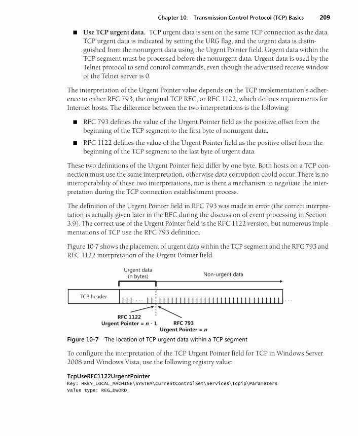
Chapter 10: Transmission Control Protocol (TCP) Basics 209
■ Use TCP urgent data. TCP urgent data is sent on the same TCP connection as the data. TCP urgent data is indicated by setting the URG flag, and the urgent data is distin-guished from the nonurgent data using the Urgent Pointer field. Urgent data within the TCP segment must be processed before the nonurgent data. Urgent data is used by the Telnet protocol to send control commands, even though the advertised receive window of the Telnet server is 0.
The interpretation of the Urgent Pointer value depends on the TCP implementation’s adher-ence to either RFC 793, the original TCP RFC, or RFC 1122, which defines requirements for Internet hosts. The difference between the two interpretations is the following:
■ RFC 793 defines the value of the Urgent Pointer field as the positive offset from the beginning of the TCP segment to the first byte of nonurgent data.
■ RFC 1122 defines the value of the Urgent Pointer field as the positive offset from the beginning of the TCP segment to the last byte of urgent data.
These two definitions of the Urgent Pointer field differ by one byte. Both hosts on a TCP con-nection must use the same interpretation, otherwise data corruption could occur. There is no interoperability of these two interpretations, nor is there a mechanism to negotiate the inter-pretation during the TCP connection establishment process.
The definition of the Urgent Pointer field in RFC 793 was made in error (the correct interpre-tation is actually given later in the RFC during the discussion of event processing in Section 3.9). The correct use of the Urgent Pointer field is the RFC 1122 version, but numerous imple-mentations of TCP use the RFC 793 definition.
Figure 10-7 shows the placement of urgent data within the TCP segment and the RFC 793 and RFC 1122 interpretation of the Urgent Pointer field.
Figure 10-7 The location of TCP urgent data within a TCP segment
To configure the interpretation of the TCP Urgent Pointer field for TCP in Windows Server 2008 and Windows Vista, use the following registry value:
TcpUseRFC1122UrgentPointerKey: HKEY_LOCAL_MACHINE\SYSTEM\CurrentControlSet\Services\Tcpip\Parameters
Value type: REG_DWORD
. . . . . . TCP header
Non-urgent data
RFC 793Urgent Pointer = n
RFC 1122Urgent Pointer = n - 1
Urgent data(n bytes)

210 Part III: Transport Layer Protocols
Valid range: 0-1
Default: 0
Present by default: No
Set this registry value to 1 to use the RFC 1122 interpretation of the Urgent Pointer field or to 0 to use the RFC 793 interpretation (the default).
TCP OptionsJust like options in the IP header extend IP functionality, TCP options extend TCP functional-ity. There are a variety of defined TCP options that are used for negotiating maximum segment sizes, window scaling factors, performing selective acknowledgments, recording timestamps, and providing padding for 4-byte boundaries. A node is not required to support all TCP options; however, the support for processing TCP options is required. The presence of TCP options is indicated by a Data Offset field with a value greater than 5 (0x5) (the TCP header is longer than 20 bytes).
A TCP option is either a single byte or multiple bytes. For multiple-byte options, the TCP option is in type-length-value format, where the length is the length in bytes of the entire option. Figure 10-8 shows the structure of multiple-byte TCP options. A TCP option type is known as an option kind.
Figure 10-8 The structure of multiple-byte TCP options
End Of Option List and No Operation
To implement 4-byte boundary support for TCP options, RFC 793 defines the following single-byte TCP options:
■ The End Of Option List The option kind set to 0 (0x00), which indicates that no other options follow. The End Of Option List option is not used to delimit TCP options. If the set of TCP options falls along a 4-byte boundary, this option is not needed.
■ The No Operation The option kind set to 1 (0x01), which is used between TCP options for 4-byte alignment. The No Operation option is not required, so TCP implementations must be able to correctly interpret TCP options that are not on 4-byte boundaries.
Maximum Segment Size Option
The TCP maximum segment size (MSS) is the largest segment that can be sent on the connec-tion. To obtain the MSS value, take the IP Maximum Transmission Unit (MTU) and subtract
. . .
Option Kind
Option Length
Option Octets
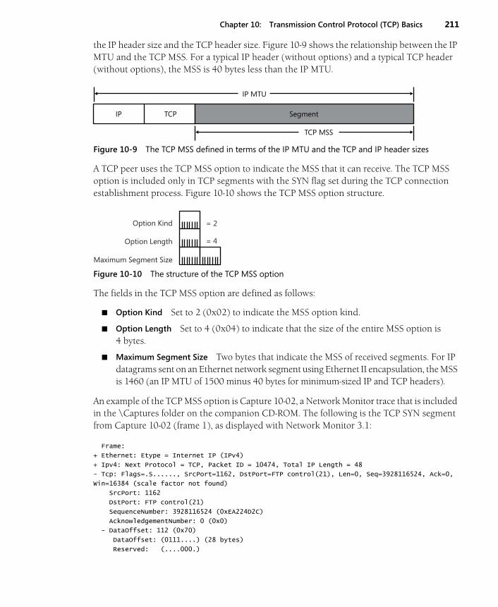
Chapter 10: Transmission Control Protocol (TCP) Basics 211
the IP header size and the TCP header size. Figure 10-9 shows the relationship between the IP MTU and the TCP MSS. For a typical IP header (without options) and a typical TCP header (without options), the MSS is 40 bytes less than the IP MTU.
Figure 10-9 The TCP MSS defined in terms of the IP MTU and the TCP and IP header sizes
A TCP peer uses the TCP MSS option to indicate the MSS that it can receive. The TCP MSS option is included only in TCP segments with the SYN flag set during the TCP connection establishment process. Figure 10-10 shows the TCP MSS option structure.
Figure 10-10 The structure of the TCP MSS option
The fields in the TCP MSS option are defined as follows:
■ Option Kind Set to 2 (0x02) to indicate the MSS option kind.
■ Option Length Set to 4 (0x04) to indicate that the size of the entire MSS option is 4 bytes.
■ Maximum Segment Size Two bytes that indicate the MSS of received segments. For IP datagrams sent on an Ethernet network segment using Ethernet II encapsulation, the MSS is 1460 (an IP MTU of 1500 minus 40 bytes for minimum-sized IP and TCP headers).
An example of the TCP MSS option is Capture 10-02, a Network Monitor trace that is included in the \Captures folder on the companion CD-ROM. The following is the TCP SYN segment from Capture 10-02 (frame 1), as displayed with Network Monitor 3.1:
Frame:
+ Ethernet: Etype = Internet IP (IPv4)
+ Ipv4: Next Protocol = TCP, Packet ID = 10474, Total IP Length = 48
- Tcp: Flags=.S......, SrcPort=1162, DstPort=FTP control(21), Len=0, Seq=3928116524, Ack=0,
Win=16384 (scale factor not found)
SrcPort: 1162
DstPort: FTP control(21)
SequenceNumber: 3928116524 (0xEA224D2C)
AcknowledgementNumber: 0 (0x0)
- DataOffset: 112 (0x70)
DataOffset: (0111....) (28 bytes)
Reserved: (....000.)
TCP MSS
Segment
IP MTU
TCPIP
= 2
= 4
Option Kind
Option Length
Maximum Segment Size
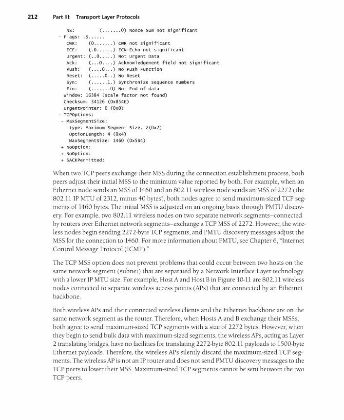
212 Part III: Transport Layer Protocols
NS: (.......0) Nonce Sum not significant
- Flags: .S......
CWR: (0.......) CWR not significant
ECE: (.0......) ECN-Echo not significant
Urgent: (..0.....) Not Urgent Data
Ack: (...0....) Acknowledgement field not significant
Push: (....0...) No Push Function
Reset: (.....0..) No Reset
Syn: (......1.) Synchronize sequence numbers
Fin: (.......0) Not End of data
Window: 16384 (scale factor not found)
Checksum: 34126 (0x854E)
UrgentPointer: 0 (0x0)
- TCPOptions:
- MaxSegmentSize:
type: Maximum Segment Size. 2(0x2)
OptionLength: 4 (0x4)
MaxSegmentSize: 1460 (0x5B4)
+ NoOption:
+ NoOption:
+ SACKPermitted:
When two TCP peers exchange their MSS during the connection establishment process, both peers adjust their initial MSS to the minimum value reported by both. For example, when an Ethernet node sends an MSS of 1460 and an 802.11 wireless node sends an MSS of 2272 (the 802.11 IP MTU of 2312, minus 40 bytes), both nodes agree to send maximum-sized TCP seg-ments of 1460 bytes. The initial MSS is adjusted on an ongoing basis through PMTU discov-ery. For example, two 802.11 wireless nodes on two separate network segments—connected by routers over Ethernet network segments—exchange a TCP MSS of 2272. However, the wire-less nodes begin sending 2272-byte TCP segments, and PMTU discovery messages adjust the MSS for the connection to 1460. For more information about PMTU, see Chapter 6, “Internet Control Message Protocol (ICMP).”
The TCP MSS option does not prevent problems that could occur between two hosts on the same network segment (subnet) that are separated by a Network Interface Layer technology with a lower IP MTU size. For example, Host A and Host B in Figure 10-11 are 802.11 wireless nodes connected to separate wireless access points (APs) that are connected by an Ethernet backbone.
Both wireless APs and their connected wireless clients and the Ethernet backbone are on the same network segment as the router. Therefore, when Hosts A and B exchange their MSSs, both agree to send maximum-sized TCP segments with a size of 2272 bytes. However, when they begin to send bulk data with maximum-sized segments, the wireless APs, acting as Layer 2 translating bridges, have no facilities for translating 2272-byte 802.11 payloads to 1500-byte Ethernet payloads. Therefore, the wireless APs silently discard the maximum-sized TCP seg-ments. The wireless AP is not an IP router and does not send PMTU discovery messages to the TCP peers to lower their MSS. Maximum-sized TCP segments cannot be sent between the two TCP peers.

Chapter 10: Transmission Control Protocol (TCP) Basics 213
Figure 10-11 Hosts connected to two wireless APs that are connected by an Ethernet backbone
If Host A were an FTP server and Host B were an FTP client, the user at Host B would be able to connect and log in to the FTP server. However, when the user issued a get or put instruction to send a file, TCP segments at the maximum size would be dropped by the wireless APs.
The only solution to this problem is to adjust the IP MTU on the wireless nodes to the lowest value supported by all the Network Interface Layer technologies on the network segment. For example, you could use the netsh interface ipv4 set interface mtu command or the MTU registry value described in Chapter 5, “Internet Protocol (IP),” to lower the IP MTU of the two wireless adapters to 1500.
TCP Window Scale Option
The TCP window size defined in RFC 793 is a 16-bit field for a maximum receive window size of 65,535 bytes. This means that a sender can have only 65,535 bytes of data in transit before having to wait for an acknowledgment. This is not an issue on typical local area network (LAN) and wide area network (WAN) links, but it is possible on newer LAN and WAN tech-nologies operating at gigabit-per-second speeds with a sizable transit delay to have more than 65,535 bytes in transit. If TCP cannot fill the logical pipe between the sender and receiver and keep it filled, it is operating at lower efficiency.
The TCP Window Scale option described in RFC 1323 allows the receiver to advertise a larger window size than 65,535 bytes. The Window Scale option includes a window scaling factor that, when exponentially combined with the 16-bit window size in the TCP header, increases the receive window size to a maximum of 1,073,741,824 bytes, or 1 gigabyte (GB). The Win-dow Size option is sent only in a SYN segment during the connection establishment process. TCP peers can indicate different window scaling factors used for their receive window sizes. The receiver of the TCP connection establishment request (the SYN segment) cannot send a Window Scale option unless the initial SYN segment contains it.
Figure 10-12 illustrates the TCP Window Scale option structure.
Host AWireless AP
Wireless AP
EthernetBackbone
RouterHost B
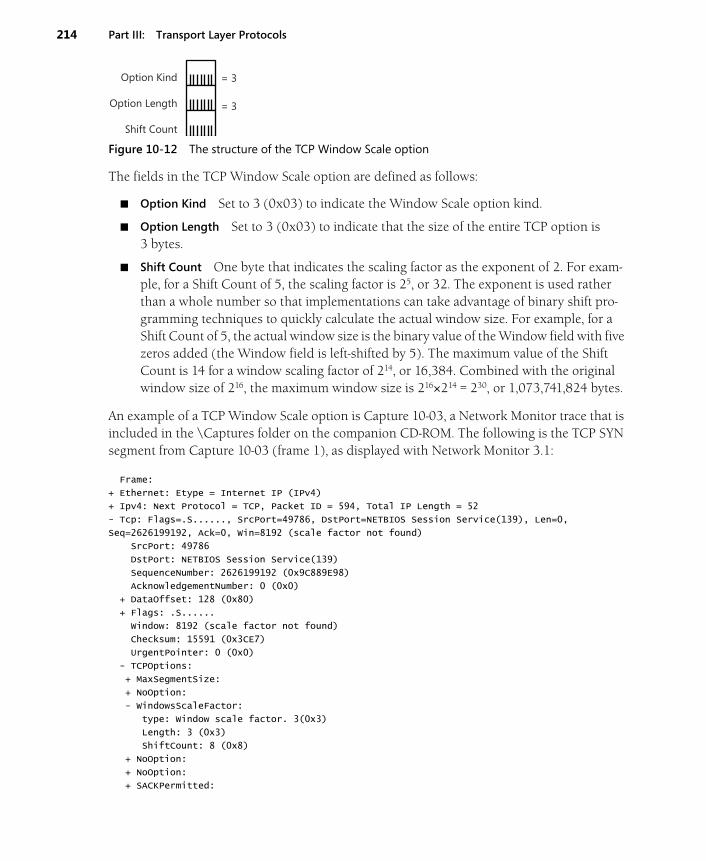
214 Part III: Transport Layer Protocols
Figure 10-12 The structure of the TCP Window Scale option
The fields in the TCP Window Scale option are defined as follows:
■ Option Kind Set to 3 (0x03) to indicate the Window Scale option kind.
■ Option Length Set to 3 (0x03) to indicate that the size of the entire TCP option is 3 bytes.
■ Shift Count One byte that indicates the scaling factor as the exponent of 2. For exam-ple, for a Shift Count of 5, the scaling factor is 25, or 32. The exponent is used rather than a whole number so that implementations can take advantage of binary shift pro-gramming techniques to quickly calculate the actual window size. For example, for a Shift Count of 5, the actual window size is the binary value of the Window field with five zeros added (the Window field is left-shifted by 5). The maximum value of the Shift Count is 14 for a window scaling factor of 214, or 16,384. Combined with the original window size of 216, the maximum window size is 216×214 = 230, or 1,073,741,824 bytes.
An example of a TCP Window Scale option is Capture 10-03, a Network Monitor trace that is included in the \Captures folder on the companion CD-ROM. The following is the TCP SYN segment from Capture 10-03 (frame 1), as displayed with Network Monitor 3.1:
Frame:
+ Ethernet: Etype = Internet IP (IPv4)
+ Ipv4: Next Protocol = TCP, Packet ID = 594, Total IP Length = 52
- Tcp: Flags=.S......, SrcPort=49786, DstPort=NETBIOS Session Service(139), Len=0,
Seq=2626199192, Ack=0, Win=8192 (scale factor not found)
SrcPort: 49786
DstPort: NETBIOS Session Service(139)
SequenceNumber: 2626199192 (0x9C889E98)
AcknowledgementNumber: 0 (0x0)
+ DataOffset: 128 (0x80)
+ Flags: .S......
Window: 8192 (scale factor not found)
Checksum: 15591 (0x3CE7)
UrgentPointer: 0 (0x0)
- TCPOptions:
+ MaxSegmentSize:
+ NoOption:
- WindowsScaleFactor:
type: Window scale factor. 3(0x3)
Length: 3 (0x3)
ShiftCount: 8 (0x8)
+ NoOption:
+ NoOption:
+ SACKPermitted:
= 3
= 3
Option Kind
Option Length
Shift Count
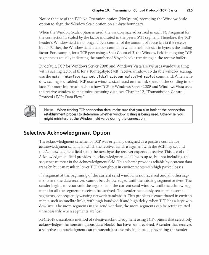
Chapter 10: Transmission Control Protocol (TCP) Basics 215
Notice the use of the TCP No Operation option (NoOption) preceding the Window Scale option to align the Window Scale option on a 4-byte boundary.
When the Window Scale option is used, the window size advertised in each TCP segment for the connection is scaled by the factor indicated in the peer’s SYN segment. Therefore, the TCP header’s Window field is no longer a byte counter of the amount of space left in the receive buffer. Rather, the Window field is a block counter in which the block size in bytes is the scaling factor. For example, for a TCP peer using a Shift Count of 3, the Window field in outgoing TCP segments is actually indicating the number of 8-byte blocks remaining in the receive buffer.
By default, TCP for Windows Server 2008 and Windows Vista always uses window scaling with a scaling factor of 8, for a 16-megabyte (MB) receive window. To disable window scaling, use the netsh interface tcp set global autotuninglevel=disabled command. When win-dow scaling is disabled, TCP uses a window size based on the link speed of the sending inter-face. For more information about how TCP for Windows Server 2008 and Windows Vista uses the receive window to maximize incoming data, see Chapter 12, “Transmission Control Protocol (TCP) Data Flow.”
Note When tracing TCP connection data, make sure that you also look at the connection establishment process to determine whether window scaling is being used. Otherwise, you might misinterpret the Window field value during the connection.
Selective Acknowledgment Option
The acknowledgment scheme for TCP was originally designed as a positive cumulative acknowledgment scheme in which the receiver sends a segment with the ACK flag set and the Acknowledgment field set to the next byte the receiver expects to receive. This use of the Acknowledgment field provides an acknowledgment of all bytes up to, but not including, the sequence number in the Acknowledgment field. This scheme provides reliable byte-stream data transfer, but can result in lower TCP throughput in environments with high packet losses.
If a segment at the beginning of the current send window is not received and all other seg-ments are, the data received cannot be acknowledged until the missing segment arrives. The sender begins to retransmit the segments of the current send window until the acknowledg-ment for all the segments received has arrived. The sender needlessly retransmits some segments, consequently wasting network bandwidth. This problem is exacerbated in environ-ments such as satellite links, with high bandwidth and high delay, when TCP has a large win-dow size. The more segments in the send window, the more segments can be retransmitted unnecessarily when segments are lost.
RFC 2018 describes a method of selective acknowledgment using TCP options that selectively acknowledges the noncontiguous data blocks that have been received. A sender that receives a selective acknowledgment can retransmit just the missing blocks, preventing the sender
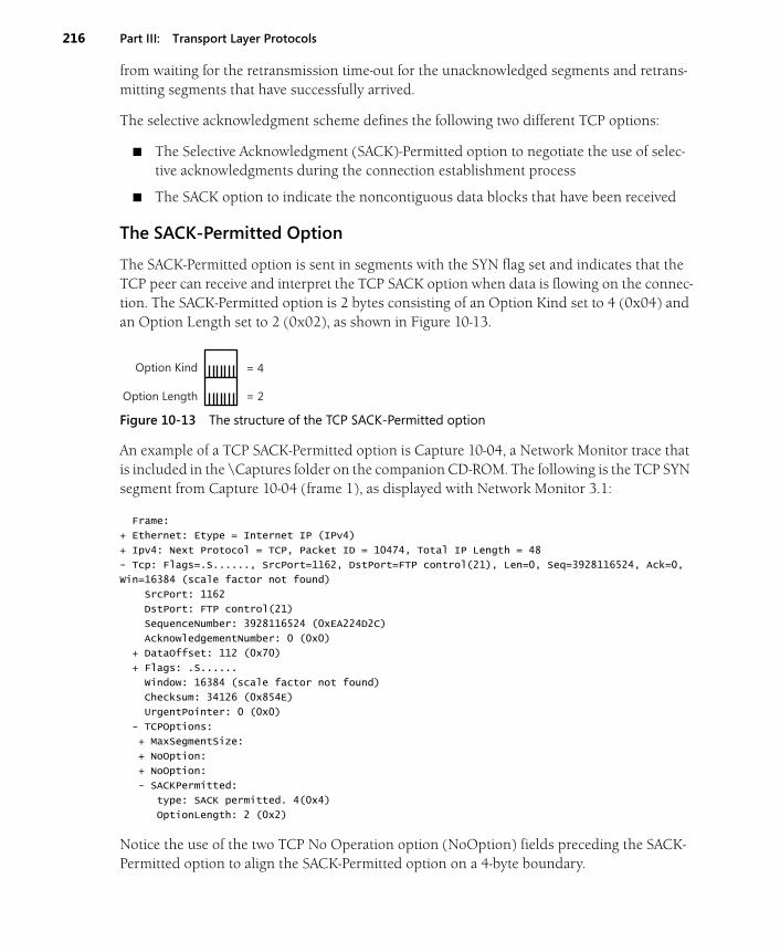
216 Part III: Transport Layer Protocols
from waiting for the retransmission time-out for the unacknowledged segments and retrans-mitting segments that have successfully arrived.
The selective acknowledgment scheme defines the following two different TCP options:
■ The Selective Acknowledgment (SACK)-Permitted option to negotiate the use of selec-tive acknowledgments during the connection establishment process
■ The SACK option to indicate the noncontiguous data blocks that have been received
The SACK-Permitted Option
The SACK-Permitted option is sent in segments with the SYN flag set and indicates that the TCP peer can receive and interpret the TCP SACK option when data is flowing on the connec-tion. The SACK-Permitted option is 2 bytes consisting of an Option Kind set to 4 (0x04) and an Option Length set to 2 (0x02), as shown in Figure 10-13.
Figure 10-13 The structure of the TCP SACK-Permitted option
An example of a TCP SACK-Permitted option is Capture 10-04, a Network Monitor trace that is included in the \Captures folder on the companion CD-ROM. The following is the TCP SYN segment from Capture 10-04 (frame 1), as displayed with Network Monitor 3.1:
Frame:
+ Ethernet: Etype = Internet IP (IPv4)
+ Ipv4: Next Protocol = TCP, Packet ID = 10474, Total IP Length = 48
- Tcp: Flags=.S......, SrcPort=1162, DstPort=FTP control(21), Len=0, Seq=3928116524, Ack=0,
Win=16384 (scale factor not found)
SrcPort: 1162
DstPort: FTP control(21)
SequenceNumber: 3928116524 (0xEA224D2C)
AcknowledgementNumber: 0 (0x0)
+ DataOffset: 112 (0x70)
+ Flags: .S......
Window: 16384 (scale factor not found)
Checksum: 34126 (0x854E)
UrgentPointer: 0 (0x0)
- TCPOptions:
+ MaxSegmentSize:
+ NoOption:
+ NoOption:
- SACKPermitted:
type: SACK permitted. 4(0x4)
OptionLength: 2 (0x2)
Notice the use of the two TCP No Operation option (NoOption) fields preceding the SACK-Permitted option to align the SACK-Permitted option on a 4-byte boundary.
= 4
= 2
Option Kind
Option Length
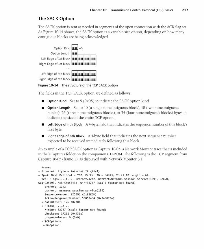
Chapter 10: Transmission Control Protocol (TCP) Basics 217
The SACK Option
The SACK option is sent as needed in segments of the open connection with the ACK flag set. As Figure 10-14 shows, the SACK option is a variable-size option, depending on how many contiguous blocks are being acknowledged.
Figure 10-14 The structure of the TCP SACK option
The fields in the TCP SACK option are defined as follows:
■ Option Kind Set to 5 (0x05) to indicate the SACK option kind.
■ Option Length Set to 10 (a single noncontiguous block), 18 (two noncontiguous blocks), 26 (three noncontiguous blocks), or 34 (four noncontiguous blocks) bytes to indicate the size of the entire TCP option.
■ Left Edge of nth Block A 4-byte field that indicates the sequence number of this block’s first byte.
■ Right Edge of nth Block A 4-byte field that indicates the next sequence number expected to be received immediately following this block.
An example of a TCP SACK option is Capture 10-05, a Network Monitor trace that is included in the \Captures folder on the companion CD-ROM. The following is the TCP segment from Capture 10-05 (frame 1), as displayed with Network Monitor 3.1:
Frame:
+ Ethernet: Etype = Internet IP (IPv4)
+ Ipv4: Next Protocol = TCP, Packet ID = 64013, Total IP Length = 64
- Tcp: Flags=....A..., SrcPort=1242, DstPort=NETBIOS Session Service(139), Len=0,
Seq=925293, Ack=55053434, Win=32767 (scale factor not found)
SrcPort: 1242
DstPort: NETBIOS Session Service(139)
SequenceNumber: 925293 (0xE1E6D)
AcknowledgementNumber: 55053434 (0x3480C7A)
+ DataOffset: 176 (0xB0)
+ Flags: ....A...
Window: 32767 (scale factor not found)
Checksum: 17262 (0x436E)
UrgentPointer: 0 (0x0)
- TCPOptions:
+ NoOption:
=5Option Kind
Option Length
Left Edge of 1st Block
Right Edge of 1st Block . . .
Left Edge of nth Block
Right Edge of nth Block
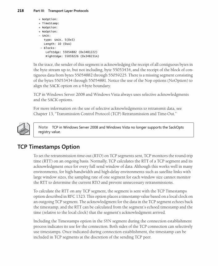
218 Part III: Transport Layer Protocols
+ NoOption:
+ TimeStamp:
+ NoOption:
+ NoOption:
- SACK:
type: SACK. 5(0x5)
Length: 10 (0xA)
- Blocks:
LeftEdge: 55054882 (0x3481222)
RightEdge: 55059226 (0x348231A)
In the trace, the sender of this segment is acknowledging the receipt of all contiguous bytes in the byte stream up to, but not including, byte 55053434, and the receipt of the block of con-tiguous data from bytes 55054882 through 55059225. There is a missing segment consisting of the bytes 55053434 through 55054881. Notice the use of the Nop options (NoOption) to align the SACK option on a 4-byte boundary.
TCP in Windows Server 2008 and Windows Vista always uses selective acknowledgments and the SACK options.
For more information on the use of selective acknowledgments to retransmit data, see Chapter 13, “Transmission Control Protocol (TCP) Retransmission and Time-Out.”
Note TCP in Windows Server 2008 and Windows Vista no longer supports the SackOpts registry value.
TCP Timestamps Option
To set the retransmission time-out (RTO) on TCP segments sent, TCP monitors the round-trip time (RTT) on an ongoing basis. Normally, TCP calculates the RTT of a TCP segment and its acknowledgment once for every full send window of data. Although this works well in many environments, for high-bandwidth and high-delay environments such as satellite links with large window sizes, the sampling rate of one segment for each window size cannot monitor the RTT to determine the current RTO and prevent unnecessary retransmissions.
To calculate the RTT on any TCP segment, the segment is sent with the TCP Timestamps option described in RFC 1323. This option places a timestamp value based on a local clock on an outgoing TCP segment. The acknowledgment for the data in the TCP segment echoes back the timestamp, and the RTT can be calculated from the segment’s echoed timestamp and the time (relative to the local clock) that the segment’s acknowledgment arrived.
Including the Timestamps option in the SYN segment during the connection establishment process indicates its use for the connection. Both sides of the TCP connection can selectively use timestamps. Once indicated during connection establishment, the timestamp can be included in TCP segments at the discretion of the sending TCP peer.

Chapter 10: Transmission Control Protocol (TCP) Basics 219
Figure 10-15 shows the TCP Timestamps option structure.
Figure 10-15 The structure of the TCP Timestamps option
The fields in the TCP Timestamps option are defined as follows:
■ Option Kind Set to 8 (0x08) to indicate the Timestamps option kind.
■ Option Length Set to 10 (0x0A) to indicate that the size of the entire TCP option is 10 bytes.
■ TS Value A 4-byte field that indicates the timestamp value of this TCP segment. The TS Value is calculated from an internal clock that is based on real time. The TS Value increases over time and wraps around when needed.
■ TS Echo Reply A 4-byte field set on a TCP segment that acknowledges data received (with the ACK flag set) that is set to the same value as the TS Value for the received seg-ment being acknowledged. In other words, the TS Echo Reply is an echo of the TS Value of the acknowledged segment.
Figure 10-16 illustrates an example of the values of the TS Value and TS Echo Reply for an exchange of data between two hosts.
Figure 10-16 An example of the use of the TCP Timestamps option.
Host A’s internal clock starts its TS Value at 100. Host B’s internal clock starts its TS Value at 9000. Segments 1 through 4 are for two data blocks sent by Host A. Segments 5 and 6 are for a data block sent by Host B. Notice how the TS Echo Reply value for the acknowledgments is set to the TS Value of the segments they are acknowledging. To prevent gaps in the sending of data from increasing the RTT, the TS Echo Reply is used for RTT measurement only if the seg-ment is an acknowledgment of new data sent.
= 8
= 10
Option Kind
Option Length
Ts Value
Ts Echo Reply
1
2
3
4
5
6
Block 1, TS Value = 100, TS Echo Reply = 9000
Ackon Block 1, TS Value = 9020, TS Echo Reply = 100
Block 2, TS Value = 158, TS Echo Reply = 9020
Ackon Block 2, TS Value = 9053, TS Echo Reply = 158
Block 3, TS Value = 9098, TS Echo Reply = 158
Ackon Block 3, TS Value = 210, TS Echo Reply = 9098
Host A Host B
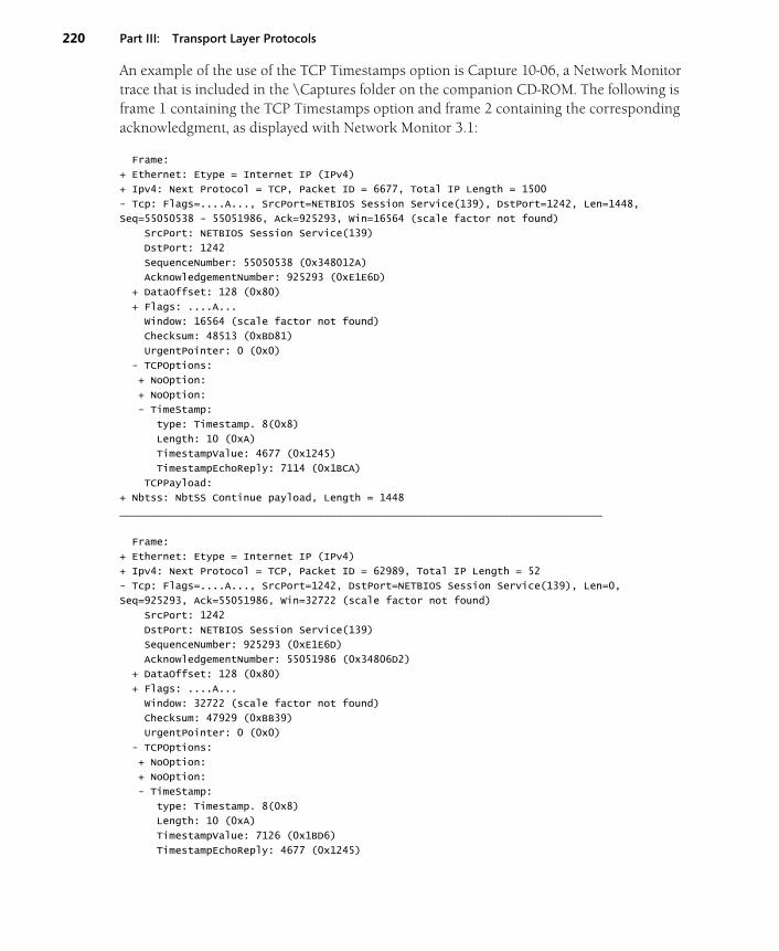
220 Part III: Transport Layer Protocols
An example of the use of the TCP Timestamps option is Capture 10-06, a Network Monitor trace that is included in the \Captures folder on the companion CD-ROM. The following is frame 1 containing the TCP Timestamps option and frame 2 containing the corresponding acknowledgment, as displayed with Network Monitor 3.1:
Frame:
+ Ethernet: Etype = Internet IP (IPv4)
+ Ipv4: Next Protocol = TCP, Packet ID = 6677, Total IP Length = 1500
- Tcp: Flags=....A..., SrcPort=NETBIOS Session Service(139), DstPort=1242, Len=1448,
Seq=55050538 - 55051986, Ack=925293, Win=16564 (scale factor not found)
SrcPort: NETBIOS Session Service(139)
DstPort: 1242
SequenceNumber: 55050538 (0x348012A)
AcknowledgementNumber: 925293 (0xE1E6D)
+ DataOffset: 128 (0x80)
+ Flags: ....A...
Window: 16564 (scale factor not found)
Checksum: 48513 (0xBD81)
UrgentPointer: 0 (0x0)
- TCPOptions:
+ NoOption:
+ NoOption:
- TimeStamp:
type: Timestamp. 8(0x8)
Length: 10 (0xA)
TimestampValue: 4677 (0x1245)
TimestampEchoReply: 7114 (0x1BCA)
TCPPayload:
+ Nbtss: NbtSS Continue payload, Length = 1448
______________________________________________________________________________
Frame:
+ Ethernet: Etype = Internet IP (IPv4)
+ Ipv4: Next Protocol = TCP, Packet ID = 62989, Total IP Length = 52
- Tcp: Flags=....A..., SrcPort=1242, DstPort=NETBIOS Session Service(139), Len=0,
Seq=925293, Ack=55051986, Win=32722 (scale factor not found)
SrcPort: 1242
DstPort: NETBIOS Session Service(139)
SequenceNumber: 925293 (0xE1E6D)
AcknowledgementNumber: 55051986 (0x34806D2)
+ DataOffset: 128 (0x80)
+ Flags: ....A...
Window: 32722 (scale factor not found)
Checksum: 47929 (0xBB39)
UrgentPointer: 0 (0x0)
- TCPOptions:
+ NoOption:
+ NoOption:
- TimeStamp:
type: Timestamp. 8(0x8)
Length: 10 (0xA)
TimestampValue: 7126 (0x1BD6)
TimestampEchoReply: 4677 (0x1245)

Chapter 10: Transmission Control Protocol (TCP) Basics 221
Notice that in the second frame the TS Echo Reply field (TimestampEchoReply) is set to 4677, echoing the TS Value field (TimestampValue) of the first frame.
In Windows Server 2008 and Windows Vista, the use of TCP timestamps can be controlled by the netsh interface tcp set global timestamps=disabled|enabled|default command. By default, TCP timestamps are disabled.
You can also use the following registry value:
Tcp1323OptsKey:HKEY_LOCAL_MACHINE\SYSTEM\CurrentControlSet\Services\Tcpip\Parameters
Value type: REG_DWORD
Valid range: 0 or 2
Default value: 0
Present by default: No
Set this value to 0 to disable timestamps. Set this value to 2 to enable timestamps. The default behavior of TCP is to not use timestamps. For more information on RTT, RTO, and retransmis-sion behavior, see Chapter 13, “Transmission Control Protocol (TCP) Retransmission and Time-Out.”
SummaryTCP provides connection-oriented and reliable data transfer for applications that require end-to-end guaranteed delivery service. Application Layer protocols use TCP for one-to-one traffic. The TCP header provides sequencing, acknowledgment, a checksum, and the identification of source and destination port numbers to multiplex TCP segment data to the proper Applica-tion Layer protocol. TCP options are used to indicate maximum segment sizes and window scaling, indicate and provide selective acknowledgments, and provide timestamps for better RTT determination.