Embed Size (px)
Citation preview

WelcomeLAUNCH VEHICLE
to(IPERATIOilS
lohn F. Kennedy Space Center
Wffi
*rffi
SECTION
1
2
3
4
5
6
7
8
9
TABLE OF CONTENTS
PAGE
INTRODUCTION 2
HISTORY 3
ORGANIZATION 7
CONTRACTOR RELATIONS L3
16KSC FACILITIES
FLIGHT HARDWARE AND CHECKOUT OPERATIONS 22
DOCUMENTATION SYSTEMS 30
ADMINISTRATION POLICIES AND PRACTICES 33
MISSIONS: PRESENT AND FUTUR E 38
BIBLI0GRAPHY (inside back cover)

Welcome to Kennedy Space Center and to the Launch Vehicle 0pera-tions Directorate.
You are now an integral part of the greatest team ever assembled toexplore and eventually to conquer the immensity of space and time. Yourefforts in every aspect of your work will contribute to the benefit of yourcountry and all mankind. Consequently, we feel that it is our duty to startyou in the right direction by acquainting you, through this handbook, withsome of the things you should know in order to make a swift adjustment toyour new job and a lasting contribution to the team effort.
As you begin to adjust to your new surroundings, you are going to findquestions this handbook does not attempt to answer. Feel free to contactyour supervisor or your LVO administration personnel, Technical Planningand Support 0ffice, for help. We wish you the best of luck in your new
efforts, and look forward to a long and productive association.
Director, Launch Vehicle 0perations

INTROD UCTION
This handbook is for use in your program of orientation in the LaunchVehicle 0perations Directorate at the Kennedy Space Center. lts purposeis to acquaint you with our history, organization, and operation. Noattempt has been made to provide a comprehensive insight into allthevarious parts of our organization and our operating methods. Rather, ourintent is to furnish you a general background that could previously only beobtained through years of experience. We hope you will find it an informa-tive and accurate portrayal of LVO 'as it really is.'
The nexi section, History, provides an insight into our origins andsome of the past accomplishments which have helped to make us tradition-ally rsuccess-oriented.' You will find that most of us feel individuallyresponsible for the quality and technical accuracy of all areas of our work.Section three provides a view of our organization in perspective with theNASA-Headquarters and Kennedy Space Center functional charts. Briefsummaries are given for each of our groups to the Branch level, and moreinformation is available on request.
The philosophy of our Civil Service/Contractor launch team interfaceis outlined in Section four, and an effort has been made to convey the depthand meaning of our close inter-relationships. 0ur present launch philo-sophy depends on the quality of our teamwork, and this section deservesparticu lar attention.
The KSC facilities, flight hardware, and checkout operations whichconcern us most directly are the topics of sections five and six. Theseareas will present, for Launch Vehicle 0perations, the most pressing tech-nical issues , for your understanding and daily attention. You can expect todevelop a detailed knowledge of most of the operating areas within yourtechnical discipline, and an overall feel for the problems and requirementsencountered in the checkout and launch of a large-scale space vehiclesystem.
Section seven is devoted to the documentation system you will en-counter (if you haven't already) in your worl< with both the contractor andcivil service organizations at KSC. Read it carefully-it provides a road-map to understanding how we function and what is required of whom. Sec-tion eight, on Administration Policies and Practices, is Similarlyimportant*and more personally oriented. The numerous references areavailable in most of our branch and section organizations. You should tryto get a quick look at a few of them during your program, Finally, ourmissions-both present and future*are presented in Section nine, round-ing out your orientation.
During your first few months you will come across many acronymsand abbreviations which you will not understand. We use them freely inall our work, and you'll find that you quickly adopt them as a part of yourdaily vocabulary. When you encounter one you don't know, ask-or checkthe library for "Space Age Acronyms" and GP-589, "A Selective List ofAcronyms and Abbreviations." AIong this same line, although we arelimited in this handbook to a minimum of detail, sources are identified bydocument number for each major topic area. Use this book as a handyreference/ and if you are unable to find the information you need, by allmeans ask someone!

,i!i-l{*S$II{3Ili,: :ir,,',l.i i:i.lrrtriui:t.
r,ir''ir,la;:l: S|*r$Y r*{:-.lr:!aa:}$i.--.r.....'-*,. - :l!9:,.:':s .' r
$,"'.. -J;:l3.3.',..:t:S$-x--,: " d ff::
- -ddtr i:li1e$S'
HISTORY
EXFII{DED S.IV B & OPEN $I-A
Early NASA. The National Aeronautics and space Administration(NASA-aame into existence on 0ctober l, lg5}, created Ov un i.t ofcongress and signed into Iaw by president Dwight D. Eisenhower. TheorganizationaI nucleus of NASA was the National Advisory committee forAeronautics, which already employed 8,040 personnel in four facilities.These were the Langley, Ames, and Lewis Research centers, and the FrightResearch center at Edwards Air Force Base. Also immediateiy *ansierredto NASA were several space programs from Defense Departmenl,s AdvancedResearch Projects Agency, incruding five space probes, three sateiiite pro-jects, and several rocket engine development programs. various activitiesunder Air Force and Army contror also went into NASA. In addition, thevanguard Project and 200 personnel from the Naval Research Laboratorybrought their expertise into the new nationar agency. The Jet Froprtiio,Laboratory of the california lnstitute of Technology b"caru , .oniri.i ug.n.yin December, 1958"
The goals of the Space Act which created the new agency were to:(1) Expand human knowledge of the atmosphere and space;-(2) -Develop
new,and improve existing, aeronautical and space vehicles; (3) perform tong-range studies of the benefits and problems expected in.aeronautical andspace activities; (4) Maintain the United states position as a leading nationin aeronautical and space science; (5) share acquired information wiih poten-tial military application with the appropriate agency; (6) cooperate *iit, ott,",nations in peaceful applications; and o) combine existing facilities andpersonnel to avoid duplication of effort.

Dr. T. l(eith G lennan was appointed the f irst NASA Administrator.He was succeeded by Mr. James E. Webb, who directed NASA for eightyears, unti I his retirement in 0ctober,1968. Dr. Thomas 0. Paine, who
had replaced Robert C. Seamans as Deputy Administrator, became Admini-strator in March 1969 " Dr. Paine announced in July 1970 that he wouldresign from this position effective September 1970. ln March 1971, the
U.S. Senate confirmed PresiJent Nixon's appointment of Dr. James C.Fletcher as the present Administrator of NASA.
The new agency's first efforts were focussed on solving problems oforganization and faci lities, formulating long-range goals, and ensuring theprogress of onnoing programs. NASA was the largest organization evercreated by the transfer of existing government projecis. During its first fewyears NASA grew faster than any agency in United States history, expandingfrom 8,000 to 16,000 personnel in its first 28 months. The detailedstory of NASA's formative years may be found in a small booklet, EP-29,"Historical Sketch of NASA," prepared by the NASA Historical Staff .
Launch Vehicle 0perations (LVO). The present Launch Vehicleopera@artered in L963. However, as
early as 1952, many of our personnel were working at what was then Cape
Canaveral in the checkout and launch of early Redstone and Jupiter weapon
system missiles under the Army Ballistic Missile Agency's GBMA) MissileFiring Laboratory (MFL). Headquartered at the Redstone Arsenal in Hunts-ville, Alabama, early launch teams traveled frequently, making only a lem-porary home in the Cape area. Then, as the program gre\4/, more permanent
assignments were made to what would eventually become the forerunner of the
Kennedy Space Center.0n July 1, 1960, the NASA George C. Marshall Space Flight Center
(MSFC) was established in what had been the Army facilities at Huntsvi lle,Alabama. The Army Ballistic Missile Agency was transferred to NASA atthat time, and its director, Dr. Wernher von Braun, became MSFC's first
FIRST AMERICA}I IH SPACE ABOARB A
MEECURY.RED$TOI{ E, 5.5.61

director. The 4,600 personnel who joined NASA included a contingent ofGerman scientists who had been active in rocket development for over twodecades. The Huntsville team had already gained experience in buildingand testing the V-2, Redstone, Jupiter, Jupiter-C, Juno, and pershinEmissiles. 0n January 37, L958, prior to the estabiishment of NASA, theyhad piaced the first U"S. satellite, EXPL0RER l, in orbit. They had alsostarted deveiopment work on the Saturn I vehicle" 0n lVlay 5, 196I , theylaunched the first Anrerican inlo space aboard a Mercury-Recistone vehicle.
The NASA Launch 0perations Directorate (L0D) was established atCape Canaveral, Florida, on July 1, 1960, as a subdivision of MSFC.It replaced the old Army iv4issile Firing Laboratory. The Air Force AilanticMissile Range, which had supported the launch of military vehicles from theCape since 1950, supported the new civilian agency on its first launches.Two years later L0D became an independent Center, the Launch 0perationsCenter (L0C), uncier the direction of Dr. l(urt H. Debus. lt was renamecjthe..lohn F. Kennedy Space Center on November 29, j"963, in honor of thelate President of ihe United States.
The first semi-permanent Launch 0perations Center organization, putinto effect in May of 1963, esiablished/ among other functions, that of thepresent Launch Vehicle 0perations, uncler the direction of Dr. Hans F"Gruene. At first the personnel of this division reporteci to Dr. von Braun atMSFC for technical and engineering funclions related to the launch vehicles,and to Dr. Debus at L0C on launch operations and administrative matters.The philosophy behind this double-reporting arrangement was that thelaunch team should be involved in the development phase of the vehicle aswellas its operational phase. 0perational and launch considerations hadto be determined early in the basic design.
Saturn/Apollo. ln IMay of 1961 President Kennedy announced theU.S. wfil?;tfempt-to fly men to the moon and bacl< within the decade.Launch vehicles far larger than anything on the drawing boards would berequired, and new launch facilities would be needed. Dr. Debus and AirForce General Leighton l. Davis performed a study for a new launch centerIocation, eventually deciding on Merritt lsland, Florida, adjacent to thethen Cape Canaveral Air Force facilities. This area, the present John F.Kennedy Space Center, became totally NASA-controlled, separating thecivilian and military manned space f light programs"
The increased size of the new and Iarger vehicles, namelythe SaturnV,dictated new and more complex facilities. Dr. Debus and others worked onpreliminary designs incorporating a totally new launch configuration, theMobile Launch concept. The Saturn V was to be assembled and checkedout on a Mobile Launcher (ML) inside the protected environment of a giantstructure called the Vehicle Assembly Building UAB). Thecompletevehicleand its launcher was then to be moved to the pad for final checl<s, fueling,and launch.
Giant dredges began prepaiing a channel into the selected area inNovember of 1962, and ground was broken for the VAB in August of 1963 "ln keeping with the number system established by the Air Force at CapeCanaveral, the new faciliiy was designated Launch Complex 39 LC-3q.work had already started on the first buildings in what was to become theindustrial area of KSC, five miles south of the launch area. while the con-struction proceeded the flight development proqram of the Saturn I vehicle
5
continued. The first U.S" manned space flight program/ Mercury, wassafely and successfully concluded, and planning began for the two-manGemini space f lights.
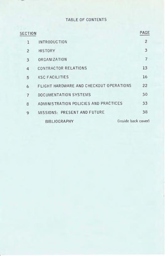
Over three years were required to build the giantfacilities needed forthe new class of launch vehicles" The first Saturn V rocket, completeexcept for rocket engines, entered the test cycle at KSC in January 1966.It emerged for its trip to the launch pad in May, just five years after Presi-dent Kennedy had established rhe goal ofa man on the moon before 1970"The Gemini program was under way on the existing Cape facilities, and thefirst flights of the Apollo program being planned for the Saturn IB vehicles.A steady series of scientific and planetary exploration satellites were beinglaunched by unmanned vehicles. The U.S. space program had grown verylarge and complex, with activities in many concurrent areas. The culnrina-tion of most of them was the launch of a space vehicle from KSC. A historyis available in "The Kennedy Space Center Story," published by the PublicAffairs off ice at KSC.
The first Saturn V flight vehicle, AS-501, was launched from Pad Aat Complex 39 on November 9, 1967. Other launches, including two inwhich three astronauts orbited the moon and returned, followed. And on
July 16 , 1969, AS-506 lifted off with astronauts Armstrong , Aldrin,and Collins. The successful completion of their mission fulfi lled the latePresident Kennedy's pledge that the U.S. would land a man on the moon
before 19 70 .
APOLLO,!ATURN L TOTF1 i: ..:..,. ...:..:., .i.;,,r1!

ORGANIZATIO N
The position of LVO within the structure of NASA can best be illus-trated by charts. NASA, as explained in the history section, is a U.S.GoVernment agency/ and its administrator reports to the President. Thenational headquarters organization is in Washington, D.C. The first chartshows the basic structure of NASA. You willnote that KSC is under theOffice of Manned Space FIight (0MSF), along with the Marshall SpaceFlight Center (MSFC) at. Huntsville, Alabama, and the Manned SpacecraftCenter (MSC) at Houston, Texas. This office is headed by Mr" Dale Myers,Associate Administrator for Manned Space Flight, who reports to the NASAAdministrator, Dr. James C. Fletcher.
The second chart shows the basic structure of KSC. Dr. Kurt Debus,the Center Director, reports to Mr. Myers. At KSC Dr. Debus is responsiblefor overall management of the Center. This includes administrative functions,the design, construction/ and maintenance of launch facilities, the checkoutof all vehicle stages and spacecraft, and the launch of assembled spacevehicles. KSC maintains close relations with the Air Force Eastern TestRange, coordinates its activities with those of its sister Centers in 0MSF,and maintains working relationships with the other NASA Centers.
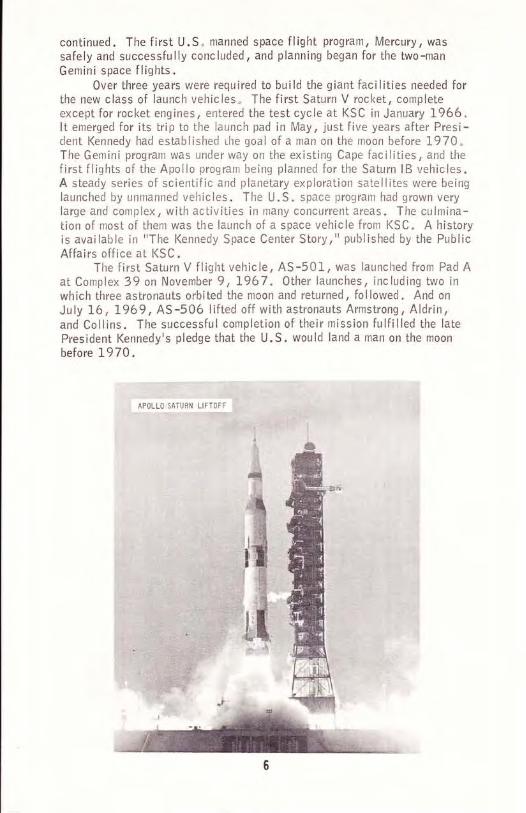
The third chart shows a breakdown of the Launch 0perations (L0)Directorate at KSC. L0, under the direction of Mr. Walter Kapryan, isresponsible for the checkout and launch of NASA flights from KSC. LVO isone of three 'second level' directorates under L0. LVO handles all stagesofall vehicles rated for manned flights. At presentthis consists of the threeSaturn V slages and two Saturn lB stages. Spacecraft 0perations handles allspacecraft associated with manned space flight programs. This was Mercuryand Gemini in the past, and Apollo and Skylab at present. Unmanned Launch0perations handles both spacecraft and vehicles for unmanned programs, suchas the 0rbiting Astronomical 0bservatory series, the Mariner interplanetaryprobes, and the various weather and communications satellites.
The fourth chart shows LVO down to the branch level" Dr. H. Grueneis Director and Mr. l.A. Rigell is Deputy Director and Chief Engineer. Thedirectotateconsistsoffouroperating divisionsandfour offices, plus a systemsengineering staff . The latter reports to the Deputy Director of LVO. Pri -marily this organization brings specialized knowledge and experience to bearwhen troubleshooting the complex problems which develop during checkoutoperations .
Three of the four operating divisions have primarily technical respon-sibilities. They are in charge of the actual testing, modifications, checkoutand launch preparations for the hardware for their specific disciplines.
The Launch lnstrumentation Systems Division, LV-l NS, is respon-sible for on-board telemetry (TM) systems, in-flight measuring equipment,and radio frequency (RF) transmitters. This group also handles ground-basedmeasuring systems. These consist primari ly of the Diqital Data AcquisitionSystem (DDAS), and the receiving station for vehicle TM data. The primarybreakout of work within LV-l NS is between the RF and TM systems and themeasuring equipment, as the chart shows.

ni EFu'-
E:P U
x Hfi 5
x *p f;o &> Yi
H '--'ffE- ^r tJF -ttt Yzz>= J <u u
d.JUI FJF L
EU > Eo(r O Ue, wo', u<= zu u=j: zF <.Y u:Z aLUJ )zur 4s1lL _.U AeOu *ll luulE2
=2 7iur OL <uOo ra =U
FI(Jft!zl','i 6 :o- Je Fqfoq
(LF q
*r e* BdF co -'l
3f E"' s-t)(J -J *
9:B$3uuZuodul!urUpoLo
>z?=
d.ouFF><<FeYtq;tu z?'=
zo9
*i=u9=r,t 19.-vULil<
"^ irF<
ouoFuF2z.
=o
doFeF
==o
F=o-UJ6
F-2.AUL==oFG
uaouN<- z.zE5i-EoOz
5.8H+il
E3H
a6b6!(J6JEuruUGo<<*2

(o
zd.IJ.J
zUJIllJL,
o-tt)
oIIJzzllJY,t
zo
uJ
d2az4Ld<YtrUr!3;(J9F3-=dH-9"'E
o-
*Zd'-e-Pi8=3i3=eG-r,OZ
ZcuO!otr 3e 4,ioF.FF ol)6>uZ"==<o6o
Fe,o
cGoq+n=- 6o .L)
g {-le,z.e65
lltF
e:6oiFo(Jotu _iu.L6sl
e.oF(J
HT6E>=FlGtuo zouI co< g
ee i-oP i'FryUOU-t
59;fJ
4qc|=,. z<
oz6 !u40 qo1E gFiT Lvue|IEe 2EUiEIE(9z)
UJL(J
(9z
bH Eez=96-l,z "vuLU
==oa=u.t6
zJo-
J
zo-oJ
oEd,oJ
o=do< E
61!Ej;zlgJ'dozLZ1rr30E2-r65u;
z.=J
uluL:L
(Jgz3zltuJEo-j
o'6 e'utF
EOa
u= osP=a#aul!!89EgEqL
uJU9a
a-O oYu-,iJ , i.5t!-oz 'E(JuL6 48;
J
ulILLo1
o;-olLiul;Looo-FUF
coE:.noF.9(J-uJ -it--oo=o
=
EoF>(J9uJ()t,
abFjfon-e.uo
E\6 EFEE=HEI;^gHti
U"du ErE e:-L tfio*=@guJel)-do;Eui6 ure.w
e.
ar,izIdtllo-o!(Jz3
10

EoLZ< tsELF@6tXxx
Vl zqrGJfEfr9ga > eiE2ts-)
r#ls-<ou<J-Uoc >o
J
-J
-oE
r@Z LL
'- EBi;tFO=E
==FoOrEdF.2=oOo<
zuJ
(oz9
d,IJ.J
o-oIIJ
9IIIJ
I(Jzf
=;r rtE-.:-6i<
iE5Hil
=->1o"6 J2"dDL LoooE&GOLE
r(JE();-' d>cooJ u?
";u-26/'6
=Eo;E3E-JEE-@"=9s33EE a,tsoo-.rtsu!LlJ5ooEg
o=o> E'drooE o
422l--o<zE*12E;EI.^rqFg'6 -'6u oEFEF
Eq@z>-itsrEJ-
d
E95E.o9oA-_LE9eo<<UE-
o=l-tJ
L
U
J
11
UU>L)oF{i E<(rL juZo -Z=r *-z<o Y
=dr +
< '-e
UUz
uz>O Ou,; _:6> !>o ;:-o-J(]
fo
ozE.UuzL(JIz<uF
=LUF
fo
o-
U
o-
Zu9uF6{u=6oF(J<=F=f<oc..:Z()UOUEE(Luod
=u_odF =6CJ> E<a2.99zon.4o2 u
uf " bUG -:
=o J
E(L
ou.ioi5:III Luao5-
d.oF=(Jouou. ii6.
59(L-lrJa
UUL
^Lo o
+ibJE ciPE E6? ii==
od
ul9a -i<= EauJ 9
6? 3Jq J<Juo uE*E JEBU
J
6-=tJ-L :
It :FF .:
vZ d.o9FZ (Jul{<eu4 =,ij5=U
Yo Et-; o
IL> -r) zA uzu==? o<-zJ;P 6
LF .:
9> i
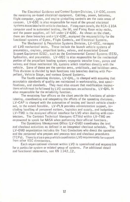
The Electrical Guidance and Control System Division, LV-G DC, coversthe remaining on-board electrical equipment. Cabling/ power, batteries,flight computer/ gyros/ and engine gimballing controls are the main areas ofconcern. LV-GDC is also responsible for most of the ground electricalsystems assoc iated w ith veh ic le chec kout. Firing room pane ls, the RCA -l 10Acomputer used in automated testing, the ML and Firing Room relay racks,and the power supplies, all fall under LV-GDC. As shown on the chart,there are three branches under LV-GDC/ assigned the responsibility for thefunctional systems of Gyros, Flight Controls, and Electrical Systems.
The Mechanical & Propulsion Systems Division, LV-MEC, managesall LV0 mechanical tasks. These include the launch vehicle systems ofpneumatics, engines, propellant tanks, valves, and associated GroundSupport Equipmenl (GSE), such as the Environmental Control Systems (ECS),hydraulics, and pneumatics" LV-MEC is also responsible for the mechanicalportion of the propellant loading system; cryogenic transfer lines, pumps andvalves; and those mechanical ML systems which interface directly with thevehicle. Some of these are the service arms, umbilicals, and holddown arms.This division is divided by task functions into branches dealing with Pro-pellant, Vehicle Stage, and various Ground Systems.
The fourth operating division, LV-QAL, is charged with assuring thatacceptable standards of quality are maintained in workmanship, test speci-fications, and standards. They must also ensure that modification instruc-tions which must be followed bv LVO contractors are adhered to. LV-QAL isalso responsible for the reliability function.
The remaining four offices on the chart provide the functions of admin-istering, coordinating and integrating the efforts of the operating divisions.LV-CAP is charged with the automation of testing and launch vehicle check-out, to the extent feasible. LV-PLN provides adm inistrative support, in-cluding handling of personnel matters, logistics and supply, and budgeting.LV-TM0 is the assigned official interface for LVO when dealing with con-tractors. The Contract Technical Managers (CTMs) within LV-TM0 areempowered to speak for NASA when performing their official functions.
The 0perations lVlanagement Office (LV-0M0) coordinates the testand checkout activities as defined in an integrated checkout schedule. TheLV-0M0 organization includes the Test Conductors who direct the operationand the personnel who prepare and process test and checkout. procedures(TC Ps) . There is a lso a'group which coord inates LVO requ i rements for supportfrom other KSC directorates.
Each organizational element within LVO is specialized and responsiblefor a particular system or related group of systems. For additional detailand functional statements, see KN 1142.12.
L2

CONTRACTOR RELATIONS
The national space program is a joint undertaking of the FederalGovernment and the aerospace industry. Contractors receive more than9O'k of the NASA budqet. This unique welding of Government and contrac-tor organizations is welldemonstrated at KSC, where integrated teams per-form complex launch missions.
The Apollo Program engages more of the Center's resources than anyother activity. The contractors who are involved with Saturn vehicle stagesand Apollo spacecraft comprise about half the total KSC manpower, and eachis responsible for his product from design through flight performance. lnsome areas NASA pays its contractors incentive fees over and above auditedcosts, adjustable according to the performance of the stage in launch prepara-tions and flight.
MSFC supervises contractors building the Saturn 1B and Saturn Vvehicles. Chrysler fabricated the first stage of the Saturn 1B, and Boeingthe first stage of the Saturn V. North American Rockwell built the secondstage for Saturn V, and McDonnell Douglas the S-lVB, which forms thesecond stage for the 1B vehicle and the third stage for the Saturn V. lnter-national Business Machines built the Instrument Units for both. At KSC allthe contractors assist inchecking out, assembling, testing and launchingthe two vehicles.
ln order to balance the contractor effort and maintain operating sche-dules, clear-cut interfaces must be established. Very frequently more thanone contractor must work in the same place at the same time. 0nly NASAcan legally instruct the separate contractors, although their work must beinterwoven and coordinated in fine detail. This is accomplished by publish-ing detailed schedules, which spell out what each contractor will be doingin the launch vehicle and spacecraft, and at whai time. These work sche-dules are planned and adjusted in frequent meetings, chaired by NASA.
Each contractor at KSC reports to the Center organization having pri-mary interest in his performance. Saturn Vehicle stage contractors operateunder the supervision of the Director of Launch Vehicle 0perations. Contrac-tors involved in technical communicationSr instrumentation and launchsupportreceive guidance from the Director of Technical Support. (The latterinclude Bendix, in charge of a variety of primari ly mechanical launch sug-port services, Federal Electric, in communication, instrumentation and datareceiving and recording, and General Electric, which provides the Accept-ance Checkout Equipment system GCE) and other electronic equipment sup-port.) North American Rockwell also supplies the Apollo Spacecraft, andGrurnman Aerospace provides the Lunar Module. Both report to the Directorof Spacecraft 0perations under these contracts. ln addition Boeing, undera separate contract, provides basic support as the Center's housekeeper,including a wide variety of services not directly related to the launchactivities. Pan American World Airways furnishes support to the DesignEngineering directorate. A host of contractors provides support in otherareas, including spacesuits, guidance systems, and simulator operation forastronaut training. ln addition, the Unmanned Launch 0perations Directoratehas a group of contractors which support the checkout and launch of unmannedscientific and technical spacecraft.
13

KSC Director Dr. Kurt Debus regularly schedules Government-
contractor staff meetings to facilitate communications between Center mana-
gers and the prime contractors. Membership includes the KSC senior staffind the contractor base managers. They meet frequently to discuss mutual
concerns in a completely frank atmosphere.The Apollo Program is the largest/ most dispersed, and most complex
scientif ic and exploratory proj:ct ever attempted. Apollo makes the building
of the pyramids, and otherwonders of history, seem small by comparison.
The program draws upon a far wider spectrum of talents than any other peace-
time effort in world history. Apollo has created an intimate and potentially
significant new sociology involving government, university, and industry.
The approach is midway between the old 'arsenal' concept used by the Army
and Navy, and the'systems' idea developed by the Air Force. ln the latter,private corporations manage, develop, and build complete weapon systems.
The NASA approach combines certain advantages of each, while drawing
upon the total abilities of both private and government organizations. The
contracting firms contribute research capabilities, manufacturing facilities,ancl some technical expertise, plus f lexible staff ing . The Government's role
is generally an integrating and directing one. ltalso acts as a central fund
of deep experience, and a point of transfer for knowledge, technology, and
new management techniques.The industry teams at KSC display an intense loyalty to their program
objectives, accepting NASA as a directive agency second only to their own
corporate management. ln daily operations NASA and contractor personnel
are virtually indistinguishable. Together they form an efficient, smoothly
functioning team. Most personnel consider working in the space program the
most fascinating job experience of their lives.One of the major impacts of the Apollo Program may prove to be as
much sociological as technical. This is the working out of techniques for
directinq the massed endeavors of scores of thousands of minds in a close-knit community of effort. This includes employees of Government, the con-
tractors, and the univerSitiesi the latter contribute heavily to the scientificaspects of the space program. This ability to coordinate diverse elements
and achievea specific greatgoal has been limited in the pastprimarily to
warfare. The completion of the Apollo Mission, a man on the moon justover eight years after that became a national objective, opens a new era.
The managiment techniques that accomplished this havq been called "poten-tially the most powerful tool in Man's history." (See "The Kennedy Space
Center Story, " Chapter XVll .)
14

6*Ba;,Xi'\'Ofr)\ )'o
[-i55"ti"
"-"rrg,illl?*'
JU*oFU,-.oE(-'
;ilFriz*\Y{r:
.1".&$'
_3
oG6EE_Eoo
ILooG
o(J
2(J
=UJ
F2e.
=F
oJJoo-
(J
-
15

KSC FACI LITIES
Launch Complex 39. LC-39 is the KSC assembly, checl<oLtt., and
IaunchTaCiTityTorSatLrrn class velricles and payloads. The vehicle stagesare assembled vertically on the Mobile Launcher (ML) and mated with a
spacecraftor otherpayload. Theassenrblyoperations andnlostof Lhechecl<outare performed in the Vehicle A:sembly Building. A large tracked vehicleca lled the Crawler-Transporter (C/T) lifts the M L and assemb led spacevehicle (unfueled) and transporis them as a unitto the launch pad. 0thermajor elements of the launch complex are the Power Substat.ion, LaunchControl Center (LCC), the crawlerway on which the C/f nroves while trans-porting the ML,/space vehicle, and the Mobile Service Structure (lvlSS).
VAB, LCC, $L'S & TURN BASIT{
Vehicle Assembly Building. The VAB is 525 feet high, 518 feetwide,@8acresofgroLrnd.ltcontains129nlilIioncubic feet of space and provides a protected environnrent for the receipt and
checkout of the stages of the Saturn V vehicles. The VAB is divided into
two rxajor areas, the high and low bays . A 92-toot-wide transfer aisleextencJs the lenqth of the building. The low bay area provides the facilitiesfor preliminary checkouland preparation of the S-ll and S-lVB stages, and
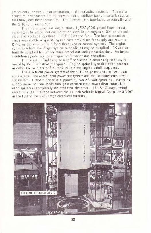
the high bay for the erection and checkout of the S-lC stage. The hiqh bay
contains four checkout bays, three ofwhich have been outfitted and acti-vated. For the Saturn V, an lVl L is broughl into one of the bays,lhe S-l C
stage is erected on it, atrd the S-l I and S-l VB stages, and the Instrunlent
Unit flU), are stacl<ed on the s-l c. Just prior to rolloLrt, the sltacecraft ispated to the launch vehicle, and the heavy ordnance is irrstalled throughout
the vehicle. The Saturn lB vehicle wiil be handled in a sinrilar tranner.
Floors of office space rise alongside the hiqh bays and portions of the
low bays. These are used prinrarily by stage contractors to house checkout
instrumentation and for qeneral office space.
16
Launch Control Center. The LCC is the focal point for control andmonitolin! of slaGI6EitT6Theckbut and launch. The LCC is connectedto the VAB by an enclosed above-ground walkway. Both buildings are farenough away from the launch pads (minimum of 3-l/2 miles) so that heavyconstruction for protection against a possible explosion at the pad is notrequ ired .
The LCC is a four-story structure, with the ground floor devoted pri-marily to offices and service areas suchas the cafeteria. The second floorhouses telemetry, data retransmission, and data recording equipment. Thethird floor divides into four separate control sections, each containing afiring room, computer room, mission control room, and a visitor gallery.Three of the firing rooms have been equipped and activated, and the fourthis utilized for program control functions. An active firing room is assignedto a specific space vehicle from the time it enters the VAB unti I launch.The fourth f loor contains firing room display equipment and miscellaneousoperating units.
Power requirements in the VAB and LCC are extensive, and are metby two separate systems, industrial and regulated industrial. The regulatedindustrial supplies the instrumentation systems and is designed to protectthem from the adverse effects of switching transients, large cycling loads,and intermittent motor start loads, The unregulated industrial servicespower systems with less stringent requirements. communication and signalcable troughs extend from the LCC via the enclosed above-ground walkwayto each ML location in the VAB.
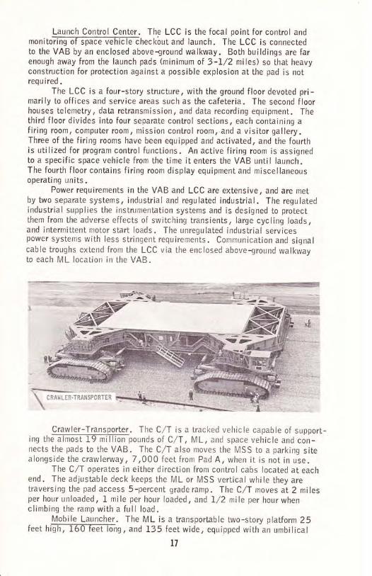
Crawler-Transporter . The C/T is a tracked vehicle capable of support-ing the-aTmoatf9 mlllion pounds of C/T, ML, and space vehicle and con-nects the pads to the VAB. the C/T also moves the MSS to a parking sitealongside the crawlerway, 7 ,000 feet from Pad A, when it is not in use.
The C/I operates in either direction from control cabs located at eachend. The adjustable deck keeps the ML or MSS vertical while they aretraversing the pad access 5-percent grade ramp . The C/T moves at 2 milesper hour unloaded, l- mile per hour loaded, and 1/2 mile per hour whenclimbing the ramp with a full load.
Mobile Launcher. The ML is a transportable two-story platform 25feet higli;f6OTeet iong, and 135 feet wide, equipped with an umbilical
l7
$*;i;:j:.iii::):iir,..:.]i\ cnawlen-rRnxsPcftTER *\

tower 380 feet high. The space vehicle (SV) is assemblecl on the platformon supports centered arouncl a 45-foot-square opening for engine flame ex-haust. The opening extencls through both floors. The unrbilical tower pro-vides horizontal service arms for access to important levels of the vehicleduring assenrbly, checkout, and servicing. The service arms also hold and
route the cables and conduils that provide the flow of essential services and
information between the SV an:J the GSE, from the time the arrns are con-nected to the vehicle until launch.
The umbilicai tower has two high-speed elevators, which service IBlandings, and which can be controlled from the firing roonrs for emergencyastronaut egress. The tower also contains distribution equipment for thepropellant, pneumatic, electrical, and instrumentation subsystems, as wellas other GSE. A 25-ton hamnrerhead crane tops the structure and can be
operated by rernote controlfrom nunterous locations on the ML.
Mobile Service Structure. The MSS provides access to those portionsof the@ot be serviced from the ML while at thelaunch pad. lt is emplaced by the C,/T in the same nranner as the ML, and
sits opposite it on the pad. The MSS is 402 feet high and weighs 12 mil-lion pounds. lt contains five work platforms, with the lower lwo verticallyadjuslable. The outboard seclions swing open and close again around thevehicle, and thesecond and third from the topare enclosed lo provide envi-ronmental control for the spacecraft.
Launch Pad. There are two launch pads, A and B, at LC-39. Bothare cellular,-TElITorced-concrete structures 42 feet high at rraximunt , attd
approximately 3,000 feet in diarneter. A ramp with a 5-percent grade pro-vides access frorn the crawlerway to the top of the pad. The C/T places the
ML r,vith the space vehicie in position on support pedestals at the pad,above a f lame trench 5B feet wide and 450 feet long. A 700-ton rnobile,
18

wedge-shaped f lame def lector is located within the trench. A two-sloryconcrete building within the fill on the west side houses environmental con-trol and pad terminal connection equipment. 0n the pad surface, elevators,staircases, and interface structures provide access to the lVlL and otherequ i pment.
Launch Complexes 34 and 37. These two complexes on CKAFS wereused f@ launch of Saturn 1B vehicles. At thesesites, the umbilical towers are permanently attached to the pad, and the ser-vice structures move on rails. The vehicle stages and payloads are assem-bled on the pad . LC-34 has one pad, while LC-37 has two pads but onlyone service structure. The LCC foreach pad is a blockhouse, locatedwithin the perimeter fence, which has been structurally designed to with-stand blast damage in case of an explosion. Spacecraft activities are moni-tored at each complex via cables which connect them to the AcceptanceCheckout Equipment (ACE) at KSC. These complexes have been deactivaled.
KSC Industrial Area. The industrial area is a large complex of build-inss loTatealT miles-6fliT of LC-39. I\4ost of the functions required tosupport operations at the launch complex area are performed here. The indus-trial area is manned by NASA and contractor managers, engineers, techni-cians and other personnel.
K$C Il{OUsTftIAL ANEA
Headquarters Building. This building is the management center of KSCIt contElns-[Ee oTfices oT-I-he Center Director and his immediate staff, theDirector of Administration; Chief Counsel; Public Affairs 0ffice; RangeSafety Staff; Director, Quality Assurance; Director, Safety 0ff ice; Manager,Apollo-Skylab Programs; and the Directors of Design Engineering, lnstalla-tion Support, Technical Support, Support 0perations, and Center Planningand Future Programs. Several KSC support contractors, including BoeingSupport Operations, Pan American World Airways, and the Bendix Corpora-tion, also occupy offices in the Headquarters Building. Service functions
19
%

available include the KSC technical libraty, microf ilm and f ilm library, filmprocessing Iaboratory, reproduction facilities, a U.S. Post 0ffice, KSC
internal mail service center, and a cafeteria. Four other government act.ivi-ties, the Marshall Space Flight Center, Defense Contract Audit Agency,NASA Regional Inspections Office and Regional Audit 0ffice, and the U.S.General Accounting Office, also occupy offices in the building.
0perations and Checkout Building (0&C). This is the largest buildingin theffireEtorates oT Launch Operations, Launchvehicle, and Spacecraft 0perations are located here. This facility contains
the S/C assembly and checkout areas, including two altitude chambers large
enough to hold the Apollo Command Module (CM) and Lunar Module (LlVl).
Living quarters, and medical and spacesuil facilities, are provided for the
astronauts' use during lheir extensive operating, training, and tesl activitiesat KSC. This building also contains laboratories for malfunction analysisand for checking out radar, communications, environmental control, Apolloguidance and navigation, stabilization and control, and electrical power
systems, as wellas biomedical and flighl experiments. The third and
fourth floors house Acceptance Checkout Equipment, the priirary system
used in S,/C checl<oLrt.Central lnstrumentation Facility. The CIF provides the major instru-
menu@ns at KSC. This facility operatesground instrumentation sysLems for telemetry, f light television, special-purpose RF systems, and iaunch data collection and retransmission to data
users at KSC, MSC, and MSFC. The CIF also provides data reduction,storage, and presentation; scientific, general-purpose, and business com-puting; and engineering and development activities for instrumentation.
Fluicl Test Area. This area contains special laboratories and testingfacilitGslispErsEci wer a wide area south and east of the 0&C Building.The clispersal is because of the hazardous pressure tests, pyrotechnic tests
and installations, performed here on the spacecraft and Lunar lVlodule, and
modular subsystems of these spacecraft. Systems tested include hypergolics,
cryogenics, and pyrotechnics. Special equipment of a potentially hazardous
nitrru, such as the nuclear power unit of the Apollo Lunar Surface Experi-
ment Package (ALSEP), is checked out and prepared for installati on here.
FIighi Crew Training Buildilg.. fllt facility, located east of the 0&[email protected] with which the astronauts and MSC f light controllers perform practice
runs. The building contains two cM simulators and one LM simulator.
0ther lndustrial Area Buildings. Numerous other buildings supplying
variou@n the lndustrial Area" These include
cafeterias, warehouses, a fire sLation, security office, utilities/ occupa-
tional health facilities, a Press Center, and others.Shops and Laboratories. There are four main types of technical
shops.@machine,andmechanical.Therearealsofacilities maintenance shops, and mobile technical shops that travel
throughout the Center. Several types of laboratory support services are
availab le.Electronic Shops. These shops have facilities for the fabrication of
electronic cont6-i-lfrne'is, patch panels, chassis, consoles, distri bution
racks, breadboards, black-box prototypes, printed circuit boards, atrd
we lded e lectron ic modu les .
20
Electrical Shops. The electrical shops have facilities for the fabri-cationTiilassem6iffi power and instrumentation cables, harnesses, and
related work. Field crews perform on-site installation, checkout, repait t
and operation of e lectric motors .
Machine Shops. The machine shops have facilities for machining,m i I I i ng;l ri ndi ng;J h-eari ng, pa i nti ng, ba k i n g, eng rav i ng, we I d i ng, a nd
drilling operations, and for sheet metal fabrication.Mechanical Shops. The mechanical shops maintain, refurbish, and
fabricate mEEIanicaTiev-ices. ln addition, they are responsible for the
operalion of mobile heavy equipment used in transporting, erecting, and
unloading boosters, assemblies, and associated space vehicle components.Facilities Maintenance Shops. These shops perform the services
require@ation,repair,installation,inspecLionand minor alterations in the areas of carpentry, painting, sign painting,sheet metal, plumbing, welding, and air conditioning.
Calibration Laboratories. These laboratories provide [email protected] for periodic recalibration where necessary/ maintenance of NASA and
other standards, and calibration and certification of working slandards.The central laboratory is located in the ClF, with several satellite loca-tions in other areas. The laboratory facilities include specially shieldedand environmenta I ly conlro I I ed rooms / specia I instrument-c leaning equip-ment, and mobile calibration equipment"
Cleaning Laboratory. This Iaboratory, located in Building K7-5 I6at LC-391 provifes precision cleaning of system hardware to any needed
level. lt is also responsible for cleaning in place those systems whichcannot be disassembled for laboratory processing.
Materials Analysis Laboratory. This laboratory, located in Room
1233m malfunction analysis, chemical analy-sis, and materials testing.
2L
FLIGHT HARDWARE AND CHECKOUT OPERATIONS
The primary flight hardware of the Apollo Program consists of a
Saturn V Launch Vehicle and an Apollo Spacecraft. Collectively, they aredesignated the Apollo/Saturn V Space Vehicle (SW.
LAUNCH VEHICLE
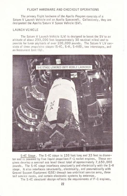
The Saturn V Launch Vehicle (LU is designed to boost the SV to analtitude of about 230,000 feet (approximately 3B nautical miles) and toprovide for lunar payloads of over 100,000 pounds. The Saturn V LV con-sists of lhree propulsive stages (S-lC, S-l l, S-lVB), two interstages, andan lnstrument Unit (lU).
S-lC Stage. The S-lC stage is t3B feet long and 33 feet in diame-ter and-is poilE76d by f ive liquid propellant F-1 rocket engines. These en-gines develop a nominal sea level thrust tolal of approximately 7,650,000pounds. The S-lC stage interfaces structurally and electrically with the S-llstage. lt also interfaces structurally, electrically, and pneumatically withGround Support Equipment (GSE) through two umbilical service arms, threetail service masts, and certain electronic systems by antennas.
The S-l C structural design reflects the requirements of F-1 engines,
22
propellants, control, instrumentation, and interfacing systems' The nlajorstructural components are the forward skirt, oxidizer tank, intertank seclion,fuel tank, and thrust slructure. The forward skirt interfaces structurally wilhthe S-lC/S-ll interstage.
The F-1 erigine is a single-start, 1,522,000-pound f ixed-thrust,calibrated, bi-propellant engine which uses liquid oxygen (L0X) as the oxi-dizerand Rocket Propellant -1 (RP-1) as the fuel. The four outboard en-gines are capable of gimbaling and have provisions for supply and return ofRP-l- as the working f luid for a thrust vector control system. The engine
contains a heat exchanger system to condition engine-supplied LOX and ex-ternally supplied helium for stage propellant tank pressurization. An instru-mentation system monitors engine peiformance and operalion.
The normal inflight engine cutoff sequence is center engine first, fol-lowed by the four outboard engines. Engine optical-type depletion sensorsin either the oxidizer or fuel tank initiate the engine cutoff sequence.
The electrical power system of the S-lC stage consists of two basicsubsystems: the operational power subsystem and the measuremenls power
subsystem. 0nboard power is supplied by two 2B-volt batteries. Batteriessupply power to lheir loads through a common main power distributor, buteach system is completely isolated from the other. The S-lC stage switchselector is the interface between the Launch Vehicle Digital Computer (LVDC)
in the lU and the S-l C stage electrical circuits.

S-ll Stage. The S-l I stage is 81.5 feet long and 33 feet in diameter,The engine system consists of five single-start, high-performance, high-altitude J-2 rocket engines of 230,OOO pounds of nominal vacuum thrusteach. Fuel is liquid hydrogen (LH2) and the oxidizer is liquid oxygen (LOX).The four outboard engines gimbal, and the fifth engine is fixed, mounted on
the centerline of the stage. A capability to cut off the center engine beforethe outboard engines may be provided by a pneumatic system powered by
gaseous helium which is stored in a sphere inside the start tank.
Major S-ll structural components are the forward skirt, the 37,737-cubic foot fuel tank, the 12,745-cubic foot oxidizer tank (with lhe common
bulkhead), the aft skirt,/thrust structure, and the S-lC/S-l I interstage. Theforward and aft skirts distribute and transmit structural loads and interfacestructurally with the interstages. The aft skirt also distributes the loads
imposed on the thruststructure by theJ-2 engines. The S-ll stage has
structuraland electrical interfaces with the S-lC and S-lVB stages, and
electric, pneumatic, and fluid interfaces with GSE through its umbilicalsand antennas.
S.IVB STAGE ERECTION
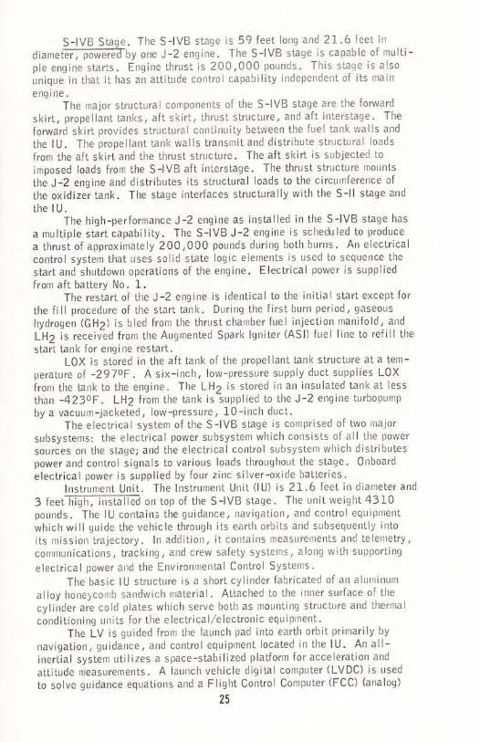
S-lVB Stage. The S-lVB stage is 59 feet long and 21..6 feet indiameter, p6wE76ilby one J-2 engine. The S-lVB stage is capable of multi-ple engine starts. Engine thrusl is 200,000 pounds. This staqe is also
uniquein that it has an attitude control capability independeni of its main
engine.The major structural components of the S-lVB stage are the foruard
skirt, propellant tanks, aft skirt, thrust structure, and aft interstage. The
forward skirt provides structural continuity between the fuel tank walls and
the lU. The propellant tank walls transmit and distribute structural Ioads
from the aft skirt and the thrust structure. The aft skirt is subjected toimposed loads from the S-lVB aft interstage. The thrust structure mounts
the J-2 engine and distributes its structural loads to the circumference of
the oxidizer tank. The stage interfaces structurally with the S-l I stage and
the I U.The hiqh-performance J-2 engine as installed in the S-lVB stage has
a multiple start capability. The s-lvB J-2 engine is scheduled to produce
a thrust of approximately 200,000 pounds during both burns. An electricalcontrol system that uses solid state logic elements is used to sequence the
start ancl shutdown operations of the engine. Electrical power is suppliedfrom aft battery No. I.
The restart of the J-2 engine is identical to the initial start except for
the fill procedure of the start tank. During the firstburn period, gaseous
hydrogen (GH2) is bled from the thrust chamber fuel injection manifold, and
LH2 is received from the Augmenled Spark lgniter (ASl) fuel line to refill the
start tank for engine restart.LOX is stored in the aft tank of the propellant tank structure at a tem-
perature of -297oF. A six-inch, low-pressure supply duct supplies LOX
front the tank to the engine. The LH2 is stored in an insulated tanl< at less
than -423oF. LHZ from the tank islupplied to the J-2 engine turbopump
by a vacuum-jacketed, low-pressure, 10-inch duct.The electrical system of the S-lVB slage is comprised of two major
subsystems: the electrical power subsystem which consists of all the power
sources on the stage; and the electrical control subsystem which dislributespower and control signals to various loads throughout the stage. 0nboard
electrical power is supplied by four zinc silver-oxide batteries.lnstrument Unit. The lnstrument unit (lU) is 21.6 feet in diameter and
3 feet-frish; iEtaI;A on top of the S-lVB stage. The unit weight 4310pounds, The IU contains the guidance, travigation, and control equiptrent
which willguide the vehicle through its earth orbils and subsequently into
its mission trajectory. ln addition, it contains treasurements atrd teletrretry,
communications, tracking, and crew safety systenrs, along wilh supporting
electrical power and the Environmental Control Systerrs.
The basic lu structure is a short cylinder fabricated of an aluminum
alloy honeycomb sandwich malerial. Attached to the inner surface of the
cylinder are cold plates which serve both as mounting structure and thermal
cond i tioning uni ls for the e lectrica l,/e lectronic equ i prnent.
The LV is guicled from the launch pad into earlh orbit primarily by
navigalion, guidance, and controlequipmenl located in the lU. An all-inertial system utilizes a space-stabilized platform for acceleration and
attitude measurements. A launch vehicle digital computer (LVDC) is used
to solve guiclance equations and a Flight control computer (FCC) (analog)
25

is used for the flightcontrol functions. The lU command system providesthe general capability of changing or inserting information into the LVDC.
FERHAND TEi;I
The instrumentation within the lU consists of a measuring subsystem/a telemetry subsystem, and an antenna subsystem. This instrumentation isfor the purpose of monitoring certain conditions and events which take placewithin the IU and for transmitting monitored signals to ground receivingstations.
The Command Communications System (CCS) provides for digital datatransmission from ground stations to the LVDC. This communications link isused to update guidance information or command certaifl other functionsthrough the LVDC.
The lU carries two C-band radar transponders for tracking. Trackingcapability is also provided through the CCS. A combination of tracking datafrom different tracking systems provides the best possible trajectory informa-tion and increased reliability through redundant data.
The Emergency Detection System (EDS) is one element of several crewsafety systems. There are nine EDS rate gyros installed in the lU. Threegyros monitor each of the three axes (pitch, roll, and yaw) thus providingtriple redundancy. The control signal processor (CSP) provides power to andreceives inputs from the nine EDS rate gyros. These inputs are processedand sent on to the EDS distributor and to the FCC. The EDS distributorserves as a junction box and switching device to furnish the spacecraft dis-
26
ll\l5Ti?u ldgT Ar0vr s-lvIIIT UruI
play panels with emergency signals if emergency conditions exist. lt also
.ortains relay and diode logic for the autcrnatic abort sequence. Arl elec-tronic timer in the lU allows multiple engine shutdowns without automatic
abort after 30 seconds of flight. lnhibitinq of automatic abort circuitry is
also provided by the vehicle flight sequencing circuits through the lU switchselector.
Primary flight power for lhe lU equipment is supplied by silver-zincbatteries al a nominal voltage level of 28 vdc. where ac power is required
within the lU it is developed by solid state dc to ac inverters. Power dis-tribution within the lU is accomplished through power distributors which are
essentially junction boxes and switching circuits.For additional details, see MSFC-MAN-5 10, "Saturn V Fliqht
Manual, SA-510. "
APOLLO SPACECRAFT
The Apollo Spacecraft (S/c) is designed to support three men in space
for periods up to two weeks, docking in space, landing on and returning from
the lunar srria.., and safely entering the earths atmosphere. TheApollo S/Cconsists of the Spacecraft-LI\,4 Adapter (SLA), the Service Module (SM),
the Command Moclule (CM), the Launch Escape System (LES), and the Lunar
Module (LM). The cM and SM as a unitare referred to as the command/
Service Module (CSM). Allthe hardware associated with the Apollo S/Cfalls within the purview Spaceffaft 0perations (SC0) under the direction of
Mr. J. J. Williams.
CHECKOUT OPERATIONS
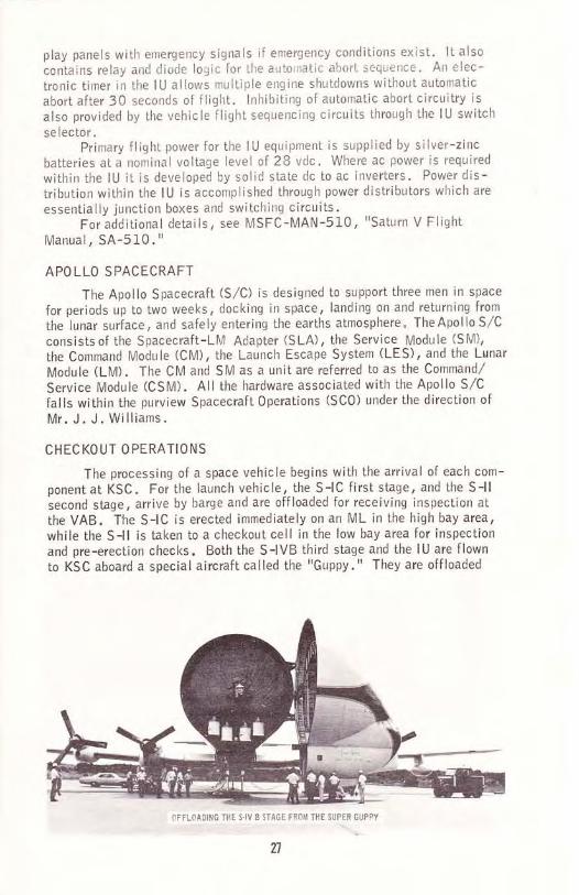
The processing of a space vehicle begins with the arrival of each com-ponent at KSC. For the launch vehicle, the S-lC first stage, and the S-llsecond sLage, arrive by barge and are offloaded for receiving inspection atthe VAB. The S-lC is erected immediately on an ML in the high bay area,while the S-ll is taken to a checkout cell in the low bay area for inspectionand pre-erection checks. Both the S-lVB third stage and the lU are flown
to KSC aboard a specialaircraft called the "Guppy." They are offloaded
27
NFTLCAD ]G TlT S-IV B 5TAOE TiOU THE SUPIiR QUPPY

and transported to the VAB low bay area for initial checl<out and prepara-tions for space vehicle buildup.
When the pre-erection preparations have been completed, the S-l landS-lVB stages, and the lU, are each separately hoisted into place and matedmechanically as wellas electrically. At this point an extensive testingsequence is undertaken to verify system perforntance in preparation for matewith the spacecraft.
Concurrent with LV checkout operations, the spacecraft modulesarrive by air transport and are processed in the 0perations and Checkout(0&C) Building in the KSC industrial area. Component and systems tests,manned altitude chamber runs, and simulated mission runs are performed.Following completion of these tests, the CM and SM are mated and tested,then the CSM is mated with the SLA and LM. The fully assembled space-craft is transported to the VAB for final erection and space vehicle mating.
After f inal mating of the SV, a comprehensive integrated testingsequence is performed to check all systems and interfaces prior to rolloutto the pad. Then upon completion of ordnance installation and separationfrom VAB systems, the Crawler-Transporter carries the entire SV on its MLto the launch pad for final tests prior to launch.
Three primary operations remain to be performed at this point. AFliqht Readiness Test (FRT) is run to sequence countdown and in-fliqhtactivities and to verify system compatibilities. A two-part CountdownDemonstration Test (CDDT) is timed and sequenced exactly as the launchwi ll be, including the use of a "launch window," to exercise every systemand all personnel involved in the mission. During the "wet" portion of theCDDtr propellants are loaded in the SV. The CDDT proceeds through a
series of procedural steps just prior to ignition time" ln the "dry" CDDT,the terminal portion of the countdown is performed without LV propellantsbut including astronaut ingress and plus-time f light functions. 0n comple*tion of the CDDT, final preparations are made for launch countdown.
t *,s n I r !

When propellants have been loaded aboard the spacecraft and theS-lVB stage Auxiliary Propulsion System (APS) tanks are filled, theordnance items are connected" Then, on launch day propellants are loadedon-board the LV, the astronauts enter the command module, and the finalcountdown is performed.
lf we have all performed out work assignments satisfactorily, andthe hardware performs as itwas designed, all these rnonths of prepara-tion and checkout culrninate in an on-time launch and a subsequentlysuccessful mission.
For additional information, see K-V-051, "Apollo/Saturn V Launch0perations Plan. r'
29

DOCUMENTATION SYSTEMS
There are five basic documenlation systems at KSC. Management
documents detail the functions and responsibilities of the various directorates.Program documents emphasize the requirements of a particular program. Con-fuactors generate documents required under their NASA contracts. Technicaldocuments provide the means for performing the primary technical functions ofthe Center, and preserve engrneering and other technical knowledge produced
at KSC. Directorate and second-level documents are issued for use only
within the individual organization, and do not materially affect oLher director-ates at KSC.
Management Documents. Management documents are issued in two
basic@mentlnstructions(KMls)andKennedyNotices(KNs). These are used for local implementation of management documents
issued by NASA Headquarters/ and to give instructions, assign responsibill-ties, and formalize policies concerning intracenter matters. ln most cases,the Headquarters directives are management in content, or technical but notidentif ied with a special program or mission. Kennedy Handbooks (KHBs)
are used where a large amount of detail must be presenled.
Program Documentation. The program managers issue Kennedy Program
D i rectiiE slKPGI wliiilTev y req u i rements on the op erati ng d i rec torate s as
necessary to complete assigned programs. Each program manager establishesthe plans, policies, and procedures to be implemented by the directoratesthrough program documentatlon trees.
conlractor-Furnished Documentation. ln large contracts, each document
to be g identif ied by a Data Requirement
Description (DRD). The DRDs are entered on the contract Data Requirements
List (DRL). The DRLs constitute important indexes for locating data/docu-ments prepared by contractors.
Technical Documentation. A wide and varied series of technical [email protected],Test 0utlines, Test and Checkout Procedures (TCPs)/ and many others.External agency requirements for KSC support are submitted to the Directorof Technical Support in the form of Program Support Requirements Documents(PSRDs). A Kennedy Program Requirernents Document (KPRD) levies pro-gram requirements on KSC support elements. A Requirements Document(RD) specifies in detail the test and checkout support requirements for a
specific operation. New or revised requirements that develop shortly before
a test are handled through "Expedite RDs. " Design Specif ications provide
a clear, accurate description of the technical requirements for a particularitem, and Design Standards establish engineering or technical limitationsand applications.
Directorate and Second-Level Directorate Documentaiion. Each
directorEte o signaturehigher than thai of the director, providing the item does not materially affectother directoraies. These documents cover a wide range of information in-structions. Those used in LV0 fall into four categories. Policy documentsprescribe, establish, or define administrative and operational guidelinesand responsibilities. 0perational documents initiate work, document pro-cedures, and establish methods for day-to-day activities. Quality documents
validate task accomplishment, specify inspection points, and process de-
30
=ulF
z.oFFztU
=f()oooJiLoE,
==
Eot-o=ozooFUFrJO
r
o=JIo
FJ
oF(Jz=L
o=oLUF
FEzl-
==o>^6E<
ofoLJ_UZEE-o-UUFo>oi!E-dSodZ6<.
FE-ooLYLUUEFO6a>=L<OFuaL@aF
azFo=zuUJ
=o==OOOEOF
=UJ6oEu>-=FE=J6-$-E>
4z6fi=JO-q>o<
uzE^JF<Zr zFo=a=U=oooozo<
U!2EUJEULzi-sd:ELEeLF
frfi=FC'AuzE<
o=Eurz6=Ua4=zosEQ
uu=o-z
EALZZEUU=Udz
=u
L.U&9-=6u-NEEOo--=FO=o<=
eZ-o=LFu?zrAUUGE5=OUz)-6i5PZLgL
E==L==6=o6
u,Uf
UO
EUJ)j=<O
lrg=L>,.E=YF)==3oo>zJ<
J
=6=EExtrYUEF<UEQF=ZpoilAa
zoaoJ-.<o=>-JO6uzt-<
oFOEFFz=oro=-d
=z*zJ=
=>o
"r=EOo, -< a
dz=!6=ou-oFd
)oA
E>FLOJ<=rEZJOUOE
rOzU
FEo
=
zoF
dN2g<
=(5;E
uzzaAazu!!o
zoFN
o=<ZaGEuO2aoazuUO
zo
=odJE<oo<+9tr;o>OJ
z>o)a6d=EOo.1-<<=E,Z
=oOUOF
J
oe.o-o-
GoFoUeo)
eoFOuEoJ
oil9e=-+z;ot-2>zJO
6d JE<oOt=EPFrzo>OJ
J
O
--o=
>=JO
z>9Jgoa>EOo.'o* L<=-Ezazo=,ou"OFoJ
rJ@
OJ&L
Foz=oJ
J
!lz66=>zJO
)oz6Tz9ot-2JO
zaUo
Uz
^oUL<uUE9ZEA-a>UJO
zoFe,
o-Ud.&
zJG
J
o=|7J
EoFoEFzoC)
GoFoEFzoO
EoFoEF=oo
Fe'-EgEE=fi
EoFoEFzoo
oFOeFzoO
EoFoEFzoo
EoFoEF=oo
zoUo
EoFOE2-oJooA
UI(L
F o)ocOJoL
-tzotrGUro
J
=.9FGUro
JzotrGULo
F=c/
t)=o
JzIFtr!Lo
=o-F7zEE=u9oL<=Zo<o=
=o-FF2
_EHJUgo[<zZ3=
=oLt-2_EgdEGgo<o=
JUGOUL=EU=OL
F&,oIFf
*4
==F F tr F Etr tr FF F F tr
N
tr
Fzu,
==UooF
L(JF
EFEo-F
EoGo
oEE Eo
oUltc
=
G(J
-
31

fective or failed equipment. And configuration management documentsauthorize modifications and provide engineering data for processing changes,
Policy Documents. Two basic policy documents provide overallguidance for all LVO activities. Administrative lnstructions (Als) are issuedto section-level organizations, as above, for LVO civil service personnelonly. The content includes policy and methods foradministrative, as opposedto operational, matters. Technical lnstructions (Tls), issued in two basicseries, cover operational policies and establish the prime documentation forday-to-day test and checkout activities. The TI series includes both LVOcivil service and contractor organizations. All LV0 personnel should befamiliar with those TI documents which directly affect their areas of work.Contact your supervisor or check the KSC Library.
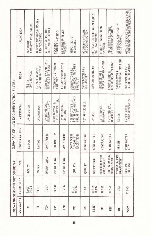
0perational Documents. Since LVO is basically an operationalorganization, most of our work involves operational documents. Thesecover everything from the generation of test and checkout procedures to arequest for telephone service. Each document is established via a Technicallnstruction which explains its f low, use/ and approval. Four particularlysignificant documents used in LV0 are: Test and Checkout Procedures(TCPs)/ used for all test and checkout operations in LVO; TroubleshootingRecord Sheets (TRSs), used to document troubleshooting operations ln anyLVO equipmen| Test Problem Reports (TPRs), which provide LVO manage-ment with an up-to-date set of open problems and tlle current status ofsolutions; and Support Requests (SRs) and Requirements Documents (RDs),which are used to request support on action from groups external to LVO.See the summary form attached at the end of this section for more detail.
Quality Documents. Documents used primarily by our Reliabilityand Quality Assurance personnel are categorized as quality documents.They are used in the identification and processing of discrepant hardware,
the recording and tracking of unsatisfactory conditions, and the processingof on-site repair work (known as 'Material Review Actions'). The mostimportant forms are the Discrepancy Records (DRs) and the UnsatisfactoryCondition Reports (UCRs). Their use and approval is also outlined in thea[tached summary.
Configuration Management. The fourth category of documentationinvo lves the paperurork requi red to request and process changes to the existingconfiguration of hardware systems. Under normal circumstances a fairly in-volved flow of paperwork, finally compiled as a Modification lnstructionPackage (MIP), as described in Tl-2-53, is required to request, initiate,and complete a hardware modification. ln the event that.a late modificationis mandatory for a launch, a Field Engineering Change (FEC) is used. Bothtypes of document require rigid compliance with established control channels,as def ined in the applicable Tl .
The remaining document listed on the summary form is called a KSCRequest" lt is an all-purpose form used by the Chief Engineer in solvingvarious significant problems which arise during the vehicle processing.For the particulars of use and approval, see Tl -2-45.
The foregoing sections have provided only the briefest of introductionsto the KSC and LVO documentation systems. A thorough familiarity withthose described, plus many not included but significant in your particulararea of endeavorfilITl speed your work and maintain the strict traceabilityand accountability that our operation requires.
32
ADMI NISTRATION POLICIES AND PRACTICES
LVO Civil Service employees perform their assignmenls within thepolicies and procedures established by the Civil Service Commission, NASAHeadquarters, the Kennedy Space Center, and the LOILVO Directorates.Following is a very brief explanation of certain policies which apply to LVOemployees. The information is intended to assist new employees with ques-tions, and to permit adjustnrent to the work assignments in a timely manner.Additional information about any of the following topics may be secured fromthe referenced policy documents, and by contacting individual supervisors.
Personnel. An Employee Record Card on each employee in LaunchVehicleTperations is maintained in the Administration Section of LVO,LV-PLN-13. These records are available to supervisors for informationregarding the employee's previous background, such as: date of last pro-motion; date of last within-grade increase; reassignments; and awards.
The ,Administration Section of LVO serves all off ices within theDirectorate, assisting in any administrative or personnel type of question orproblem. AII requests for personnel actions are initiated in this Section.
Tours of Duty (KMl 3610.1A, "Duty Hours") . There are several sban-dard tours of duty, such as: 8:00-4:30 ,730-4:00,3:30-12:00 p.m.,and 7:00-3:30, on a five day work week-Monday through Friday. Themajority of the engineers in LVO work on a ,First 40 Hour Tour.r' Thisenables the supervisor to use a variable work day in scheduling his employ-ees, to cover all emergencies and special schedule requirements that may
ari se .
Pay Period Time & Attendance (KHB 9620.18/AD, "Time andAttendance Reporting"). Pay is based on a two-week period, with pay daysonTondaf;teepl wlen a holiday falls on Monday, in which case the priorFriday is pay day. Pay checks may be mailed to your bank, home, or hand-carried to you in the office upon yourwritten request" Payroll deductions forCredit Unions, Bank Accounts, and U.S. Savings Bonds may be arrangedin any amount, at your request"
The secretary in your immediate off ice is your timekeeper. She main-tains a Time &Attendance record noting your time in and out each day, and
any sick or annual leave taken. At the end of a two-week period this recordis certified by your supervisorand submitted to the Payroll 0ffice, for issu-ance of your pay check.
Leave (KMl 3630.lB/AD, "Leave Administration"). An employeeearnssick a ust be approved byby each employee's supervisor prior to taking off. Eachemployee must serve90 days before he is eligible to take annual leave. lf time needs to be takenother than sick leave before the employee has completed his 90 days, it willbe charged as leave without pay (LWOP). Sick leave may be taken as you
earn it. You earn four hours each pay period for sick leave. Annual leaveis governed by the number of years service (civil service and military) youhave to your credit. 0ne to three years service-earn four hours each payperiod; three to fifteen years-six hours per pay period; and fifteen years and
over-eight hours per period. After you have been on-board for one continu-ous year, your annual leave for the year will be advanced to you for use' lf
33

you use all your advanced leave before you have earned itand terminate,you must pay for the leave you have used but not earned.
Promotion (NHB 3335 .OEC , 3335.1). A Merit Promotion Plan func-tions d announcements of openingsto afford all those qualified to apply for positions that are being upgraded,(that is, from one GS grade to the next highest GS grade). A StandardFom 172 is submitted to the Placement & Recruitment 0ffice for evalua-tion by a selected panel. When a selection is made, the employees arenotified whether they have qualified and if they have been selected for thenoted position. An employee can also be promoted in the job he occupies,if the position warrants a higher grade; this is accomplished after a speci-fied period of time.
Training (KMI 3410 "2/AD , "Employee Di'velopment and Training ").LVo T@
Systems Training. LV Contractors conduct extensive formalclassroom training courses on the Saturn Apollo Launch Vehicle and Asso-ciated Ground Support Equipment. LV employees participate in appropriatec lasses .
Safety Training. There are mandatory safety training classes,/courses for LVO operational personnel, depending upon the work assign-ment of the ind iv idua I .
Management Training. The extent of participation in this cate-gory depends upon the responsibilities of the individual employee. A widerange of management training courses are offered"
College Training . LV personnel participate extensively incollege training courses offered locally by Colleges and Universities. De-pending on need, LV personnel travel to Universities,/Colleges out of thearea for special courses in state-of-the-art categories.
Seminars, Professional Meetings , Symposiums. LVO personnelparticipate extensively in professional organizations and are afforded theopportunity, from time to time, to attend seminars, conferences, meetingsof professional organizations, and special events.
Each year LVO supervisors meet with their employees to projectfuture training plans and programs for the organization and each individual.The projections of requirements for each LV0 employee are submitted to theKSC Training 0ffice, for budget purposes hnd for the planning of classesthroughout the fiscal year. Each LVO Division/Office has a training coor-dinalor to assist and monitor the training plans of each respective employee.LV also has a Directorate Training Coordinator to work with the KSC Train-ing 0ff ice for overall management of the training activities
"
ln addition to formal training opportunities for LVO employees, thereis a comprehensive on-the-job training program for each new employee, with-in his assigned LV organization. Every possible effort is made to provideall LV employees with the training necessary for the organization to perform
its mission, and to permit individual employees to develop professionally.LVO also participates in a center-wide Co-op Training Program, SummerEmployees Program, and other similar programs.
Travel (KMl 9710.2CA5, "lmplemeniation of NASA Travel Regula-tions "oi-TE-mporary Duty Assignments (TDY) to other NASA Centers and to Con-tractor/y'endor facilities. Travel orders are issued for all travel and
34
require the approval of individual supervisors. Preparation of travel ordersand coordination of reservations and airline tickets is accomplished witheach employee's off ice, in conjunction with the KSC Travel 0ffice. Strictcontrols are applied to travel, and funding is budgeted on a monthly basis.
Security and Badges.(KMl I6I0.1/lS, "Personnel Security Program"),ln addto each employee when he starts employment, LVO employees may have workassignments which require additional badges. Employees working in hazard-ou6 areas or within the launch complex will be given special safety trainingand subsequently assigned special badges. These will permit them to gainaccess to various special work areas in the operational complex. Specialsecurity badges called APIP (Apollo Personnel Identification Program) arealso required of personnel performing critical functions with the LaunchVehicle or Ground Support Equipment. Arrangements for special trainingand special badging are made by LV supervisors.
Government Furnished,/Owned Motor Vehicles at KSC (KMI 6730.1A/rs)
"NA3A by the General Services Administration (GSA). Allvehicles havinga 'G' prefix on the tag are owned by GSA and are utilized by KSC CivilService Organizations and their Contractor organizations. Those trucksdisplaying an'NA' prefix on the tags are owned and maintained by NASA.All these vehicles are for official use only and are available through yourassigned office. A valid Government Motor Vehicle Permit is required tooperate any official vehicle at KSC" Drivers of government vehicles may
obtain gasoline at the GSA Service Station located in the KSC Motor Pool.It should be noted that vehicles are almostalways in short supply. Allemployees are encouraged to uti lize the KSC Shuttle Bus System, whichruns through most areas at 10 minute intervals throughout the majority ofeach workday"
Government Motor Vehicle Permit (KMl 6730.2A45). When it isdeterm y for the em-ployee to obtain a permit to perform his duties, the employee completes theapplication sheet, KSC Forn 7441, and submits it to his supervisor.These permits are valid (after the individual signs) for a 3 year period,unless sooner revoked for reasons mentioned in the above cited reference.lnstructions for completing the application are listed on the reverse side ofthe form. Permits should be carried along with the individualrs statelicense, ready for display when required.
Motor Vehicle Parking at KSC (KMl 1620 .2A4S). The above refer-enced ning parking atKSC for both private and government vehicles. Ample space is availableand most areas are unrestricted unless fenced or specifically marked byindividual name or other identification. Employees are cautioned not toillegally park a vehicle, whether government owned or private" The refer-enced Instruction also conlains regulations concerning motor vehicle traffic.These regulations are established for KSC, Cape Kennedy Air Force Sta-tion (CKAFS), and Patrick Air Force Base (PAFB) by a jointoperating andsupport agreement. A point system is in effect through this agreement, andcovers traffic violations committed on allthree installations. This is a
reciprocal arrangement, and copies of all citations are forwarded to AFETR/KSC Traffic Recods Bureau for recording purposes" The traffic violation
35

point assessment listing/ as outlined in attachment A to the above citedreference, notes penalties for each violation" A total of 12 points in any24 month period may result in suspension of your operator's permit"
Ciothing (K[/ll 173A.lA/SF, "Protective Clothing and Equipmentr').Specia e
operational testing and countdown/launch of the Saturn Apollo LaunchVehicie. These requirements generally consist of protective-type clothing(coveralls, smocks, hardhats, rubber aprons, etc.) and are provided by theLVO supply organization, LV-PLN-1 1.
Supply and Control of Government Property (l(HB 4000.1A/lS;LV -Al ec -essarylo accomplish their work assignments, Certain supplies and nraterialsare expendable in nalLrre (consumed !n use) and do not require accoLrntability.LVC has two Property Accourrts managed by two Supply Specialists /PropertyCustodians. For items requiring accountability (capilaiized personal pro-perty, sensitive items, personally attractive items, and itenrs under
$200.00 ilhich require periodic scheduled maintenance), the supplyspecialists are available to help LV employees. They will fill their reqLr ire-ments for tools, special clothinE, requisit,ions, and other supply,/materialitems. No individual lvill receive, transfer, loan, cannibalize or dispose ofassigned propert! without coordination with the Supply Specialist/PropertyCustodian.
Spare parts support for systems operated,/maintained by LV0 personnelmay be secured from lhe LV Components Logistics Section, LV-PLN-11.
Reference documents cover this area in detail and should be reviewedwhen requirements for Supply/Logistics support develop.
Procurement of Equipment, Supplies, Spares and Services (AI 5100,drd. 3paris, or-s, or;peciEl services not locally available, arise occasionally in thevarious work assignments. The referenced Administrative lnstruction callsout a step-by*step procedure to follow in the preparation of a ProcurementR eq ues t.
Telephones and 0ther Communication Systems. Telephones and othercommuniCaLions systems are provided to LV employees for off icial business.Telephone service to other NASA Centers and other government facilitiesis provided by the Federal Telephone System (FTS). Requirements to calloff the FTS network may be met by calling the KSC 0perator and asking forassislance. All long distance telephone calls off the FTS net require iden-tification of the caller and an authorization number. Datafax service is alsoavailable. See your supervisor for proper justification.
NASA Locator (KMI 1590.3A, "NASA Personnel Directory"). Acenter mpletedwhen entering on duty. A copy is sent to the Locator File,onetotheAdmini-stration 0ffice in KSC, and another to the Administration Section in LVO.This enables anyone calling in to contact an employee.
Medical Services (KMl 1B 10.18/lS, "KSC Medical and Environmen-tal Healt ram"). KSU has a contract with Pan American World Airwaysa contract with Pan AmericantoTurr;lsfi medl#I services. LV employees may make use of this service foremergencies and physical examinations. Emergency treatment is avai lablein the VAB, at the Main Dispensary on the Cape Road (Cape Kennedy), and
at the Main Dispensary in the KSC lndustrial Area. The referenced KMI
36
should be reviewed for the requirements established for taking physicalexaminations.
lnventions and Suggestions (KMl 1450.1BIAD). NASA employeesare en t of operating pro-cedures, techniques, equipment design, and safety practices. All sugges-tions are carefully evaluated, and if accepted, the contributor is eligiblefor a monelary award. A suggestion is submitted as either a recommendedcost reduction/ or as a new invention. If the suggestion reduces costs,the employee should contact the cost reduction representative for his divi-sion and obtain a NASA Form #1105A. The cost reduction representativewillassist in completing and submitting this form.
ln the case ofan invention, the employee should apply to the PatentCounci l,/Techno logy Uti I i zation Off icer for an award. The invention shou ldbe considered of value as a scientific or technical contribution, and of majorimportance in advancing the state of knowledge in aeronautical or spaceactivity. The invention must also have been developed during the inventorrstenure as a NASA employee.
Library (KMl 2240.1/lS). The KSC Library, located in Room 130Iof the@vides a service quite vital to LaunchVehicle 0perations in that it is the only complete reference source at thecenter. Although most LVO divisions maintain a convenient assortment offrequently used documents, none is equipped with extensive related material"Shelved volumes, as wellas professional periodicals, technical papers/specifications and standards, and locally generated documents are main-tained by a competent library staff. Reading rooms are provided for theconvenience of the user. A Iibrary card is used for checkout purposes andmay be obtained by completing KSC Form 16-24 at the library desk.
Activities Available to KSC-LVO Employees.oors/ a Kennedy Ath-
letic and Recreation Social (KARS) membership is available to KSC CivilService and Contractor personnel. Faci Iities are available for picnics,swimming, boating, and camping. Clubs of various types function withinthe framework of KARS, (i .e., Gun Club, Softball Leagues, Tnvel Club.)For more information call the KARS Manager at Complex 99"
Service Station. An automobile service station is located inthe KSC IndustrialArea. Emergency service may lce secured.
Credit Union. The KSC Credit Union is open to all LVO em-ployees. Details concerning membership, savings accounts, and loans maybe secured by contacting the Credit Union Office, which is located inRoom 1484 of the Headquarters Building.
The U.S. Post 0ffice, a Sundry Store and a Barber Shop, all locatedin KSC Headquarters Building, are available to LV employees.
NOTEFor additional information regarding support services,see KHB 86t0.IA/AD, "Support Services Handbook."Also, check the classified listing in your KSC telephonebook for specific requirements (Security, Supply,Med ica I , etc .) .
lt

MISSIONS: PRESENT AND FUTURE
Present. There are two f inal missions left in the Apollo Program;numbelfT6fid 17. These f lights will conclude the first phase of thegreatest feat of exploration performed by Mankind to date. Both missionswill utilize the Lunar Rover and enlarged scientific experiment packages, toprovide the highest possible return of information from the surface of themoon. The Satrrn V vehicles wi ll be launched by LVO in the establishedmanner.
,a,
The second major on*going program is the Skylab mission. Skylab isa prototype space station, designed to test the abilityof mento liveandworkin zero gravity for extended periods. Sky lab wi I I contain by far the mosl com-plex scientiflc instrumentation placed in Earth orbit by the USA. Basically,Skylab adds another uti lization for Apollo Programhardware. Themajorcom-ponent, the 0rbiting Workshop, is a Satrrn V third sLage whose interior has
been outf itted with living and laboratory facilities. Modif ied Apollo space-craft will carry crews to the workshop and return them to Earth.
s

Other main components are the Multiple Docking Adapter (MDA), whichprovides the docking port for the Apollo spacecraft, and the Airlock Module(AM), which has an airlock for extravehicu Iar experiments, the main communi-cation and data links, and the environmental, thermal, and elecLrical power
systems controls. The primary scientif ic payload is a separate modulecalled the Apollo Telescope Mount (ATM), which houses the solar experi-ments. The ATM is designed to perform the most comprehensive study ofthe sun ever attempted above the atmosphere.
The Skylab Program will require four separate launches. The first willbe of a modified Saturn V carrying the three connected modules of the labora-tory, plus the ATM. The following three will be of Saturn IBs, carryingthree-man astronaut crews. The Saturn V will be launched first with theinitial Saturn lB flight scheduled for 24 hours later. The astronauts willreturn to Earth after 28 days in orbit, and a second crew will be launchedlater for a 56 day stay. A third and f inal crew will follow for another 56day mission.
One ML at KSC is in process of being modified to launch Saturn lBvehicles from a Saturn V pad. A second ML is being modified for the new
configuration of the Saturn V required Lo carry the Skylab. The adaptationof Saturn V equipment for Saturn lB launches enabled NASA to deactivatelB Complexes 34 and 37 on Cape Kennedy, for a substantial anticipatedreduction in launch operations costs. A second Skylab mission may be
authorized for lhe 1974*75 time period, but this is uncerLain at present.The Unmanned Launch Operations Directorate of KSC has a continu-
ing series of unmanned scientific/ weather observation, and communicationssatellites scheduled for launch from the present throughout the decade of theseventies. Detailed information on these missions can be obtained from theKSC Public Affairs off ice.
Future. The major program expected to heavily impact KSC during thedecade-6TTh-e seventies is called the Space Transportation System (STS).This consists of four basic units: A space logistics transport, commonlycalled the Space Shuttle; A six to twelve man space station in semi-permanent orbit; An atomic-powered rocket that would be used only in spacefor long-duration missions such as flights to Mars; and a space tug thatwould shift personnel and equipment from low to high Earth orbits, and land
them on the moon or Mars and return them to lunar or Martian orbit.Space Shuttle. Thisvehicle is plannedas atwo-stage transport
with both stages poweredwith liquid hydrogen and oxygen engines. lt will be
capable of carrying from 25,000 to 50,000 pounds into Earth orbit.Each shuttle would have a useful lifetime of I00 flights. The vehiclewould be launched in the vertical position like a rocket, but both stageswould return to Earth in a horizontal landing mode, in the manner of an air-plane. KSC has proposed to house the shuttle configurat.ion in the VAB,using a IVI L and the Crawler,/Transporter to move the f light-ready vehicle to
the launch pad. A landing strip would be constructed nearby for the return-ing stages. (An interim approach using a standard one-shot rocket for the
first stage, with orbiting upper stage as described above, is under consider-ation at present.)
Space Station. Several studies ltave been performed on possible
space station configurations. The most likely is a modular concept, where

launches would orbit large sections that could be joined together in space.The exact number and type of launches required is unknown at present.
Alomic-Powered Rocket. A vehicle system wherein hydrogengas is heaied in a reactor andexpelled through a rocket nozzle to providethrust as a monopropellant has been in development for several years. Thisvehicle would be launched as cargo on a conventionally-powered chemicalrocket, and would operate only in space. When perfected, this vehiclewould be capable of up to two years of operational life on a single mission.Its primary application would be as a transport between orbits for transplane-tary fl ig hts .
Space Tug. The space tug would be a uti lity vehicle, primari lyfor use where the distances involved make utilization of the atomic rockettoo expensive or too hazardous. Short trips in Earth orbit, such as from therelatively low orbit of the space station, at less than 300 miles altitude, tosynchronous satellites at 23 ,000 miles altitude, would be one application.Another would be as a landing vehicle on the moon and later Mars, wherethe one-sixth gravity of the moon and the roughly four-tenths gravity of Marsmake the utilization of small vehicles practical. Like the atomic rocket, itwould be placed in orbit by a chemical rocket"
President Nixon has established the following specific objectives forthe space program:
1 . Exp lore the moon.2. Explore the planets and the universe.3. Reduce the cost of space operations.4. Extend man's capability to live and work in space.5, Hasten and expand the practical applications of space technology.6. Encourage greater international cooperation in space.
"M we entelt cL nua deeade," the President said, ,,tae ahQ- corwciou,to[ tlLe daet that man ia al.to entwLng a netu h,i-.ttoaic etu. tcttt thz6Ur^t 4^9, ho hat ne-a.che_d betlond h,is ptane.t; dott the n-e,tt. od LLmzwz uti-tl tluLnlz od ountelvu aa.mQ-n (nom the_ pl_aie.t Eah-th. It",i-t mqhope. that .Ne ca.n p(.an and woth Ln d waq wtich ma.lze.t u.t 1c.,toud. bottl odthe..p.La.ne.t [ttctm wLuLch tlQ, comQ- and o(1 o-un abi]-i.tq to tna.vet bztlond..u.,,
40

BIBLIOGRAPHY
EP-29 "Historical Sketch of NASA"
KSC-625 "The Kennedy Space Center Storyl
GP-589 "A Selective List of Acronyms and Abbrevia-ti ons "
MOSER "Space Age Acronyms" Published by Plenum
Pub I ishers
K-V-051 "Apollo,/Saturn V Launch 0peralions Plan"
KMI 1620.1AllS "Motor Vehicle Parking at KSC"
KMI 1730.1AlSF "Protective Clothing and Equipment"
KHB 4000.1AllS "supply and Control of Document Property"
Al 5100, dated 3/LO/71 "Procurement of Equipment, Supplies, Spares,and Services"
KMI 1590.3A "NASA Personnel Directory"
KMI 1810.tBlS "KSC Medical and Environmental HealthProgram "
KMI 1450.1BlAD "lnventions and Suggestions "
KMI 2240.lAS "LibrarY"
KMI 3610.1A "DutY Hours "
KHB 9620 .1B,/AD "Time and Attendance Reporting "
KMI 3630 .IB/AD "Leave Administration"
NHB 3335 .OEC , 3335.1 ,Promotion"
KMI 34I0.2AD "Employee Development and Training "
KMI 9710 .TCAS ',lmplementation of NASA Travel Regulationsll
KMI 1610. 1/l S "Personnel Security Program"
KMI 7630.1AlS "Government Furnished,/0wned Vehicles at KSC"
KMI 6730 .2AlS "Government Motor Vehicle Permit"
E
E
E
E
I
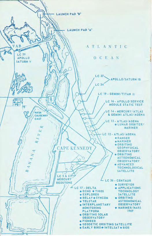
LAUNCH PAD .B'
LAUNCH PAD .AO
LC5&6MERCU RY
REDSTONE
ATLANTIC
OCEANN
l
i
I:
r!L);
iry&J
A
q
/ ni,
ti// ,',i
tii'l,{ t
Jltrt*,"4-',
lt\(
,t;,l/d
,il
l,'/ z'r. r7 - DELrA(i oEcHo rrtRos,/ c EXPLORER
. RELAY. SYNCOM
. TELSTARo INTERPLANETARY
MONITORINGPLATFORM
r ORBITING SOLAROBSERVATORY
o PIONEERo GEODETIC ORBITING SATELLITE. EARLY BIRD. INTELSAT. BIOS
VAB
CAPE KENNEDY
LC 37-
) reor-r-ozsAruRN rB
LC 34'
LC I9. GEMINI,/TITAN II
LC 16. APOLLO SERVICEMODULE STATIC TEST
LC I4 " MERCURY,/ATLAS& GEMINI ATLAS/AGENA
LC I3 " ATLAS,/AGENAo LUNAR ORBITER,/
MARINER
LC I2. ATLAS,/AGENA. RANGERo MARINERo ORBITING
GEOPHYSICALOBSERVATORY
o ORBITINGASTRONOMICALOBSERVATORY
. ADVANCEDTECHNOLOGICALSATEL LITE
LC 36. CENTAURo SURVEYOR. APPLICATIONS
TECHNOLOGYSATELLITE
. ORBITINGASTRONOMICALOBSERVATORY
o MARlNER/MARSI 969