Embed Size (px)
Citation preview

DREDGING RESEARCH PROGRAM
TECHNICAL REPORT DRP-92-4
o LABORATORY TESTING OF METHODSTO INCREASE HOPPER DREDGE PAYLOADS:
AD-A257 270 MODEL HOPPER BIN FACILITY ANDIIIllhIlll~lIllfl11lllllllllill CENTRIFUGAL SOLIDS CONCENTRATOR
by
Stephen H. Scott, Walter Pankow, Thad C. Pratt
Hydraulics Laboratory
DEPARTMENT OF THE ARMYWaterways Experiment Station, Corps of Engineers
3909 Halls Ferry Road, Vicksburg, Mississippi 39180-6199
-S ELECTE
NOV9 19
August 1992
jFinal Report__
Approved For Public Release; Distribution Is Unlimited
Prepared for DEPARTMENT OF THE ARMY )US Army Corps of Engineers
Washington, DC 20314-1000
Monitored by Coastal Engineering Research CenterUS Army Engineer Waterways Experiment Station
3909 Halls Ferry Road, Vicksburg, Mississippi 39180-6199
Under Work Unit No. 32475
The Dredging Research Program (DRP) is a seven-year program of the US Army Corps of Engineers.DRP research is managed in these five technical areas:
Area 1 - Analysis of Dredged Material Placed in Open Water
Area 2 - Material Properties Related to Navigation and Dredging
Area 3 - Dredge Plant Equipment and Systems Processes
Area 4 - Vessel Positioning, Survey Controls, and Dredge Monitoring Systems
Area 5 - Management of Dredging Projects
Destroy this report when no longer needed. Do not returnit to the originator.
The contents of this report are not to be used foradvertising, publication, or promotional purposes.Citation of trade names does not constitute an officialendorsement or approval of the use of such
commercial products.

Form ApprovedREPORT DOCUMENTATION PAGE OMB No. 0704-0,8
Puatic reporting burden for this collection Of information is estimated to average 1 hour per response, including the time for review g instrutions, searching existing data sources.gathering and mantainng the data needed, and completig and reviewing the collection of information. Send comments regarding this burden estimate or any other aspect of thiscollection of information, including suggestions for reducing this burden, to Washington Headquarters Services, Directorate for Information Operations and Reports. 121S JeffersonDavis Highway. Suite 1204. Arlington. VA 22202-4302, and to the Office of ManaKgement and Budget, Paperwork Reduction Project (0704-0188). Washington. DC 20503.
1. AGENCY USE ONLY (Leave blank) 2. REPORT DATE 3. REPORT TYPE AND DATES COVEREDAugust 1992 Final repo rt
4. TITLE AND SUBTITLE 5. FUNDING NUMBERS
Laboratory Testing of Methods to Increase HopperDredge Payloads: Model Hopper Bin Facility and WU 32475Cp,•ntrifuanl qn1idn Concentrator6. AUTHOR(Sj
Stephen H. ScottWalter PankowiThad C Pratt7. PERFORMING ORGANIZATION NAME(S) AND ADDRESS(ES) B. PERFORMING ORGANIZATION
REPORT NUMBER
USAE Waterways Experiment Station, HydraulicsLaboratory, 3909 Halls Ferry Road, Vicksburg, MS39180-61999. SPONSORING/MONITORING AGENCY NAME(S) AND ADDRESS(ES) 10. SPONSORING/MONITORINGDepartment of the Army, US Army Corps of Engineers, AGENCY REPORT NUMBER
Washington, DC 20314-1000
USAE Waterways Experiment Station, Coastal Technical ReportEngineering Research Center, 3909 Halls DRP-92-4Ferry Road. Vicksbur. MS 39180-619911. SUPPLEMENTARY NOTES
Available from National Technical Information Service, 5285 Port Royal Road,Springfield, VA 22161.12a. DISTRIBUTION /AVAILABILITY STATEMENT 12b. DISTRIBUTION CODE
Approved for public release; distribution is unlimited.
13. ABSTRACT (Maximum 200 words)
It is common practice to fill beyond overflow on dredge hoppers and scowsto achieve load gains. However, some of the US Army Corps of Engineers Dis-tricts do not permit overflow due to actual or perceived environmental oreconomic reasons. It is generally not known whether overflowing is beneficialin increasing the hopper payload in fine-grained sediments (silt and claysize), although some studies have indicated a minimal increase in hopper loadswhen filled to overflowing. Under the Dredging Research Program (DRP) Work
Unit, "Technology for Monitoring and Increasing Dredge Payload for Fine-Grained Sediments," several experimental methods were investigated to determinetheir effect on increasing the payload of fine-grained dredged material.
Several devices were tested in a scale sidel hopper constructed at theUS Army Engineer Waterways Experiment Station Hydraulics Laboratory. Thesedevices included three types of hydrocyclanes (centrifugal separators), various
(Continued)
14. SUBJECT TERMS 15. NUMBER OF PAGESDiffusers Hydrocyclones Overflow 44Fine-grained sediment Inclined plates Plates 16. PRICE CODEHopper dredges Load gain17. SECURITY CLASSIFICATION 18. SECURITY CLASSIFICATION 19. SECURITY CLASSIFICATION 20. LIMITATION OF ABSTRACT
OF REPORT OF THIS PAGE OF ABSTRACT
UNCLASSIFIED UNCLASSIFIED I I _I
NSN 7540-01-280-5500 Standard Form 298 (Rev 2-89)Prpsr,ribd by ANSI Sid 119-18298-102

13. ABSTRACT (Continued).
diffuser designs, and different arrays of internally mounted inclined plates.A solids concentrator device was also evaluated for increasing the load of finesediments in the model hopper.
This report presents the description and method of the testing programsand the study findings. The inclined plate and solids concentrator devicesdemonstrated some level of success when tested with silt-sized materials (par-ticle size 10 to 63 microns). The inclined plate method was the most success-ful for increasing payload in the model hopper; however, prototype use of thistechnique could substantially increase the weight of a hopper dredge unless alightweight version is developed. The technique may have economic benefits inseparating sediments out of the effluent of a confined disposal site, or whenspecialized separation techniques might be required in the cleanup ofcontaminated sediments.
PREFACE
This study was conducted by the Hydraulics Laboratory (HL) of the US
Army Engineer Waterways Experiment Station (WES) during the period April 1989
to October 1990. The study was sponsored by the Headquarters, US Army Corps
of Engineers (HQUSACE), as a part of the Dredging Research Program (DRP), Work
Unit 32475, "Technology for Monitoring and Increasing Dredge Payload for Fine-
Crained Sediments," managed by the WES Coastal Engineering Research Center
(CERC). HQUSACE Technical Monitor for DRP Technical Area 3, Dredge Plant
Equipment and Systems Processes, was Mr. Gerald Greener. Mr. Robert H.
Campbell was Chief Technical Monitor.
This report was prepared by Messrs. Stephen C. Scott, Walter Pankow, and
Thad C. Pratt of Estuaries Division (ED), HL. The work was performed by
Messrs. Scott, Pratt, and Dr. J. Machemehl of Texas A&M University, College
Station, TX. Dr. Machemehl, employed under an Intergovernmental Personnel
Agreement, assisted with the initial testing. Mr. Larry Caviness, ED,
assisted with laboratory analysis. Mr. Leo Keostler, Instrumentation Services
Division, WES, assisted with the instrumentation design and installation.
Technical review was performed by Mr. Allen M. Teeter and other ED staff. The
solids concentrator tests were conducted under contract by the Advanced
Resource Development Corporation (ARD), Columbia, MD, with Dr. E. B. Silverman
the principal investigator.
The study was conducted under the general supervision of Mr. Frank A.
Herrmann, Jr., Director, HL; Mr. Richard A. Sager, Assistant Director, HL; and
Mr. William H. McAnally, Jr., Chief, ED. Mr. William H. Martin, ED, was the
Manager of DRP Technical Area 3. Principal Investigators were Mr. Teeter and
Ms. Pankow. Program Manager of the DRP was Mr. E. Clark McNair, Jr., CERC.
Dr. Lynn Hales, CERC, was Assistant Program Manager. This report was edited
by Ms. Marsha C. Gay of the WES Information Technology Laboratory.
At the time of publication of this report, Director of WES was
Dr. Robert W. Whalin. Commander and Deputy Director was COL Leonard G.
Hassell, EN. _ ForLIS 9tUI
For further information on this report or on the Dredging Research 191mow)d"ktiflosatiL
Program, please contact Mr. E. Clark McNair, Jr., Program Manager,
at (601) 634-2070.Dishribultiew/Availability Code
4 A-st l and/or1Dist fSpecial

CONTENTS
Lame
PREFACE .................................................................... 1
SUMMARY................................................................3
PART I: INTRODUCTION .................................................... . 5
Background ............................................................ 5Objective ............................................................ 5Approach ............................................................. 6Previous Work ....................................................... 6
PART II: MODEL HOPPER TEST FACILITY ...................................... 8
Facility Description ............................................... 8Materials Used in the Tests ......................................... 8
PART III: DIFFUSER AND HYDROCYCLONE TESTS .............................. 11
Diffuser Test Series ................................................. 11Hydrocyclone Test Series ............................................. 12
PART IV: MODEL HOPPER INCLINED PLATE CONFIGURATION TESTS ............. 14
Background ........................................................... 14Theory of Operation for Inclined Plate Settlers ................... 14Model Hopper Test Configuration ...................................... 17Test Results and Discussion .......................................... 19Dimensional Scaling of the Inclined Plate Settler ................. 25Analysis and Discussion of Test Results ............................. 29
PART V: CENTRIFUGAL SOLIDS CONCENTRATOR STUDY ........................ 31
Background ............................................................ 31Theory of Testing Program and Approach .............................. 31Materials Used in the Tests .......................................... 31Small-Scale Tests ..................................................... 32Large-Scale Tests .................................................... 33Test Results and Discussion .......................................... 34
PART VI: CONCLUSIONS AND RECOMMENDATIONS ............................... 37
Conclusions .......................................................... 37Recommendations ...................................................... 37
BIBLIOGRAPHY ............................................................... 39
TABLE I
2
SUMMARY
Within the Dredging Research Program (DRP) Work Unit, "Technology for
Monitoring and Increasing Dredge Payload for Fine-Grained Sediments," several
types of devices were laboratory tested to determine their effect on increas-
ing the loads of fine-grained dredged materials.
Several devices were tested in a scale model hopper constructed at the
Hydraulics Laboratory (HL), US Army Engineer Waterways Experiment Station.
The model hopper was used to test various devices and techniques designed to
increase the payload of fine-grained sediments typically found in dredge hop-
pers. The devices tested included three types of hydrocyclones (centrifugal
separators), various designs and configurations of diffusers, and different
arrays of internal inclined plates. The hydrocyclone and diffuser tests indi-
cated a limited success in increasing the amount of sediments separated out of
a clay slurry. The most successful device tested was a series of inclined
plates mounted inside the model hopper. Although the inclined plate method
indicated up to a 50 percent increase in solids retention for low-density silt
slurries (1.045 and 1.090 g/cm3 ), the costs of retrofitting a hopper dredge
combined with the additional weight of the plates cannot be justified at this
time.
The effect of a centrifugal solids concentrator for increasing the pay-
load of fine-grained sediments was also tested under contract. The Advanced
Resource Development Corporation (ARD) conducted two series of controlled
tests using a centrifugal solids concentrator device and selected sediment
materials. These tests indicated that the application of a concentrator would
be of some benefit. However, as noted previously, the cost of installing this
device on a hopper dredge would probably be prohibitive.
The inclined plate method demonstrated the potential for significantly
increasing the payload of silt-sized material in dredge hoppers. Although the
application of this technique to prototype dredge hoppers may not be practical
unless a lightweight version is developed, it may hold promise for other
specialty applications in which solids are to be separated from a discharge
stream. In some cases, environmental regulations prohibit the discharge of
solids from confined disposal sites. Weight-efficient inclined plate designs
can be used to clarify a continuous discharge from these sites. Specialty
barges can be designed and fabricated with inclined plate configurations for
3
limited specialty dredging applications in which maximum solids loading is
critical.
4
LABORATORY TESTING OF METHODS TO INCREASE HOPPER DREDGE PAYLOADS:
MODEL HOPPER BIN FACILITY AND CENTRIFUGAL SOLIDS
CONCENTRATOR
PART I: INTRODUCTION
Background
1. The US Army Corps of Engineers is responsible for the maintenance of
over 40,000 km of inland and intracoastal waterways. One of the primary Corps
responsibilities is the channel maintenance of approximately 19,000 km of the
principal waterways. The annual dredging results in about 200 million cubic
metres of dredged materials at a cost of over 300 million dollars. The dredg-
ing program is administered by the Corps, but the majority of the actual work
is contracted to private dredging companies.
2. A variety of dredge plants are engabed in dredging operations, but
the dredge of choice for open-water long disposal hauls is the hopper dredge.
The hopper dredge, which is specifically designed to both dredge and haul the
materials to a remote disposal site, uses a trailing suction draghead to
remove sediments from the channel bottom.
3. To economize the hopper dredging process, it is a common practice to
fill past overflow in an attempt to retain additional solids in the hopper.
Due to the lack of data, it is not known whether overflowing fine-grained
sediments is beneficial for increasing the hopper payload. However, some of
the Corps Districts do not permit overflow due t- actual or perceived environ-
mental or economic disadvantages. Under the Dredging Research Program (DRP)
Work Unit, "Technology for Monitoring and Increasing Dredge Payload for Fine-
Grained Sediments," devices were tested to determine their effect on increas-
ing the payload of fine-grained dredged materials.
Objective
4. The objective of this study was to evaluate the effectiveness of
selected devices and techniques for increasing the fine-grained sediment pay-
load in dredge hoppers. Devices that attach to the end of the discharge
5

pipeline or are installed within the hopper bin were evaluated based on their
effectiveness in separating the solids fraction of an inflowing slurry and the
feasibility of prototype application. This report presents the description,
methods, and results of the testing program.
A2groach
5. Three types of devices were tested in a scale model hopper con-
structed at the US Army Engineer Waterways Experiment Station (WES). The
first class of devices tested were flow diffusers, which attach to the end of
the discharge pipe. These devices reduce the turbulence of flow into the
hopper, creating an environment conducive to particle settling. The second
class of devices tested, hydrocyclones and a solids separator, impart centri-
fugal forces to the inflowing slurry to separate the solids fraction. The
third type of device tested was an inclined plate configuration in the hopper.
The inclined plates create a d-isity gradient within the slurry, which
increases the settling rate of solids from the suspension.
Previous Work
DMRP studies
6. Within the Dredged Material Research Program (DMRP), one method
studied included the use of a hydrocyclone (Tiederman and Reischman 1973).
The results indicated that hydrocyclones were potentially effective in concen-
trating the solids fraction of dredged material slurries. However, the scale
of the hydrocyclone used in those particular tests wa; very small, and there
was no attempt to scale up for prototype application. The hydrocyclone tests
performed in the WES model hopper facility (described in Part II) are larger
in scale and volume of materials used.
Related DRP studies
7. Palermo and Randall (1990) conducted a Corps-wide survey on the
practices and problems associated with the economic loading of hopper dredges
and scows. They concluded that the practice of overflowing fine-grained sedi-
ments for the purpose of economic load gain is questionable. The particle
size and settling velocities of the fine-grained materials (silt and clay
size) are much lower than for sandy materials; therefore, they tend to stay in
6

suspension. The survey indicated that during periods of overflow conditions,
much of the released slurry has the same density as that retained in the
hopper itself.
Field studies of centrifugal separators
8. Field studies using centrifuge methods for dewatering river bottom
sediments have proven successful. A study conducted by the consulting firm
Camp, Dresser and McKee for the Florida Department of Environmental Regulation
(Priede 1990) evaluated the performance of a centrifuge for dewatering con-
taminated river bottom sediments from the Ribault River in Jacksonville, FL.
9. The results of the study indicated that total suspended solids
recovery from sediment slurries can range from 50 percent to a high of 95 per-
cent if a polymer addition technique is used. This study not only verified
the use of centrifugal separators for separating the solids fraction from
dredged slurries, but also demonstrated that i. was more economical to de-
water the dredged sediments onsite and transport them to confined disposal
sites than to haul the dredged materials off to open-water sites for disposal.
7
PART II: MODEL HOPPER TEST FACILITY
Facility Description
10. The scale model hopper used for the tests (Figure 1) was con-
structed at WES. The model, constructed of 0.64-cm-thick aluminum plate, had
a capacity of approximately 0.77 mi3 . The shape of the bin was similar to that
of a section of an actual hopper dredge. The hopper was 0.91 m square at the
top, with the bottom of the bin sloped toward the center such that the hopper
depth was 0.76 m at the sides and 0.91 m at the center (Figure 2). The model
hopper was suspended from an A-frame with a load cell attached to determine
the weight of materials within the hopper. Two 946-2 mixing tanks were in-
stalled next to the model for mixing and storing a kaolinite clay or silt
sediment slurry. The piping and slurry supply network consisted of 5-cm-diam
polyvinyl chloride (PVC) pipe and an electric pump (Figure 3). Predetermined
amounts of kaolinite or silt and water were mixed to the desired density for
these cont.rolled tests.
11. The load cell was capable of recording the hopper weight as a func-
tion of time. Density samples were taken as a vertical depth profile every
15 cm in the hopper. The overflow density was sampled by attaching a funnel
to the top edge of the hopper (Figure 4). Samples of the overflow were col-
lected in 100-ml bottles and analyzed with a digital hand-held density meter.
Materials Used in the Tests
12. The model hopper tests were conducted with both silt and clay
slurries. The clay was a commercial kaolinite with a mean particle size of
about 2 microns. The silt material was a naturally occurring sediment that
was passed through a 200 mesh sieve to remove the sands. The naturally occur-
ring clay fraction of the silt material was essentially removed by suspending
the material in water and draining off the suspended clays. Particle size
analysis was performed on the silt using standard pipette and electronic par-
ticle sizing methods. The median particle size range was 12 to 17 microns,
indicating a fine to medium silt. The characteristic settling velccity was
determined to be 0.020 cm/sec at a bulk wet sediment density of both 1.045 and
1.090 g/cm3 .
8

Figure 1. The model hopper laboratory test facility
0.91 m
0.76 m0.91 m 0.91 m
TOP VIEW END VIEW
SIDE VIEW
Figure 2. Model hopper dimensionL
9

Slurry Mixing Tank ModelFeed Pump Hpe
(• • Overflow Basin
Return Une PumSK•'
Figure 3. Model hopper overflow test loop
Figure 4. Overflow from an inclined plate test series
10
PART III: DIFFUSER AND HYDROCYCLONE TESTS
Diffuser Test Series
13. The initial laboratory tests were designed to determine the influ-
ence of the method of slurry discharge into the model hopper on the retention
rate of fine sediments. These tests investigated the use of diffusers con-
nected to the slurry discharge pipe. A diffuser is a device designed to
evenly distribute the feed slurry into the hopper, thus reducing the turbu-
lence within the hopper and creating a quiescent flow environment conducive to
particle settling. The tests were designed so that the hopper was allowed to
overflow for a specific period of time while the total hopper load was
monitored.
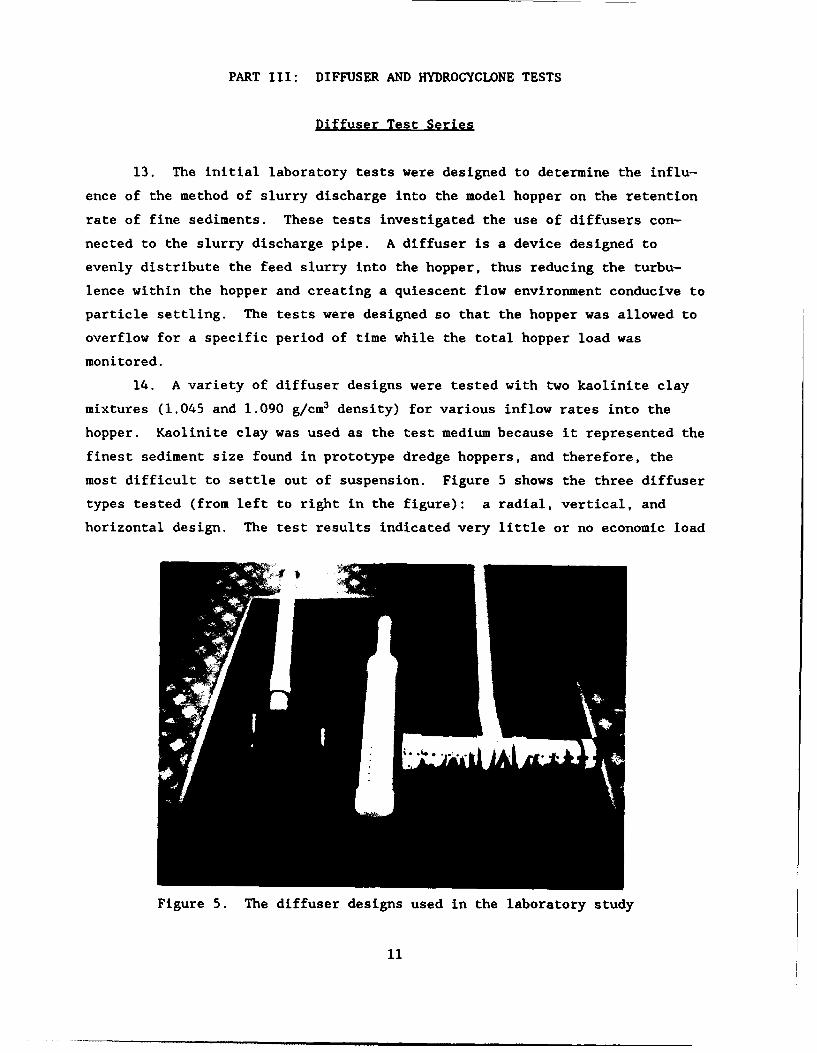
14. A variety of diffuser designs were tested with two kaolinite clay
mixtures (1.045 and 1.090 g/cm3 density) for various inflow rates into the
hopper. Kaolinite clay was used as the test medium because it represented the
finest sediment size found in prototype dredge hoppers, and therefore, the
most difficult to settle out of suspension. Figure 5 shows the three diffuser
types tested (from left to right in the figure): a radial, vertical, and
horizontal design. The test results indicated very little or no economic load
Figure 5. The diffuser designs used in the laboratory study
11

gain from the use of these devices for the two kaolinite clay mixtures tested.
These diffusers offered no distinct advantage over conventional methods of
placing slurry into hopper dredges; therefore, no further diffuser laboratory
tests were conducted.
Hydrocyclone Test Series
15. A second class of devices was investigated for attachment to the
discharge pipe. These devices are designed to concentrate the slurry solids
before they are introduced into the hopper. They are commonly referred to as
centrifugal separators or hydrocyclones. They operate on the principle of
solid-liquid separation due to centrifugal forces imparted to the slurry.
Figure 6 shows a typical hydrocyclone design tested in the model hopper facil-
ity. The slurry is introduced tangentially into the top portion of the coni-
cal device at a given flow rate. The conical shape of the device imparts a
vortex motion to the slurry, creating significant centrifugal forces on the
slurry that tend to concentrate the solid particles near the walls of the
device, where they move downward and are eventually discharged at the bottom
orifice as a thickened sludge. The clarified effluent is discharged as over-
flow through the top of the device.
Figure 6. A hydrocyclone design being tested on the model hopper
12

16. The test results indicated that the hydrocyclone device was not
successful in increasing the solids load in the hopper when used with a kao-
linite clay suspension. Although literature suggests that hydrocyclones can
efficiently separate particles within the 10- to 30-micron size range (fine to
medium silts), the hardware requirements and subsequent required alterations
to a working hopper dredge were not economically justifiable. Therefore,
laboratory tests of the hydrocyclone centrifugal separator with a silt slurry
were not conducted, and testing of the centrifugal separator was discontinued.
13
PART IV: MODEL HOPPER INCLINED PLATE CONFIGURATION TESTS
Bakground
17. Tests were conducted to investigate the effect of inclined baffle
plates in'a model hopper bin on the loading rate of fine-grained sediments.
This settling phenomenon, referred to as the lamella or Boycott effect, accel-
erates the separation of suspended solids from the liquid media by creating a
density gradient within the slurry. The less dense clarified liquid is then
transported along the downward facing inclined plate to the surface of the
hopper. As the clear water flows upward toward the surface, the higher
density solids-laden water flows to the bottom of the hopper. The theory of
inclined plate settlers and a description of the laboratory tests that were
conducted to investigate the use of inclined plates in hopper bins to increase
the settling rate of fine-grained sediments are presented in the next two
sections. The test facilities and procedures are described, as well as the
results.
Theory of Operation for Inclined Plate Settlers
18. One of the earliest observations of the increased settling rate of
suspensions between inclined plates was reported by Boycott (1920). He
observed that blood in inclined test tubes settled out at a faster rate than
in vertical tubes, and that the settling rate increased with an increase in
angle of inclination from the vertical axis. Other studies were conducted
which qualitatively verified Boycott's observations.
19. A good qualitative description of the enhanced settling of suspen-
sions between inclined plates was given by Zahavi and Rubin (1975). They con-
ducted tests with a clay suspension (particle density 2.71 g/cm3) between in-
clined plates. Dye was injected into the suspension between the plates and
the enhanced settling phenomenon was observed. Immediately after the well-
mixed suspension was placed between the plates, a clear water layer appeared
under the downward facing plate. Dye injections showed that clarified liquid
moved out of the suspension into this layer under the plate and flowed along
the plate up to the surface.
20. Nakamura and Kuroda (1937) were among the first researchers to
14
present a quantitative theoretical model for settling between inclined plates.
They conducted settling experiments with square test tubes inclined at 45 deg,
and obtained good correlation between experimental and theoretical results.
21. Many studies have been conducted using a continuum mechanics
approach to theoretically describe the inclined plate phenomenon. Of particu-
lar importance to the understanding of the inclined plate effect was the work
of Acrivos and Herbolzheimer (1979). Their work verified the theoretical
limitations of the inclined plate settlers and gave good insight into the
design and operation of these devices.
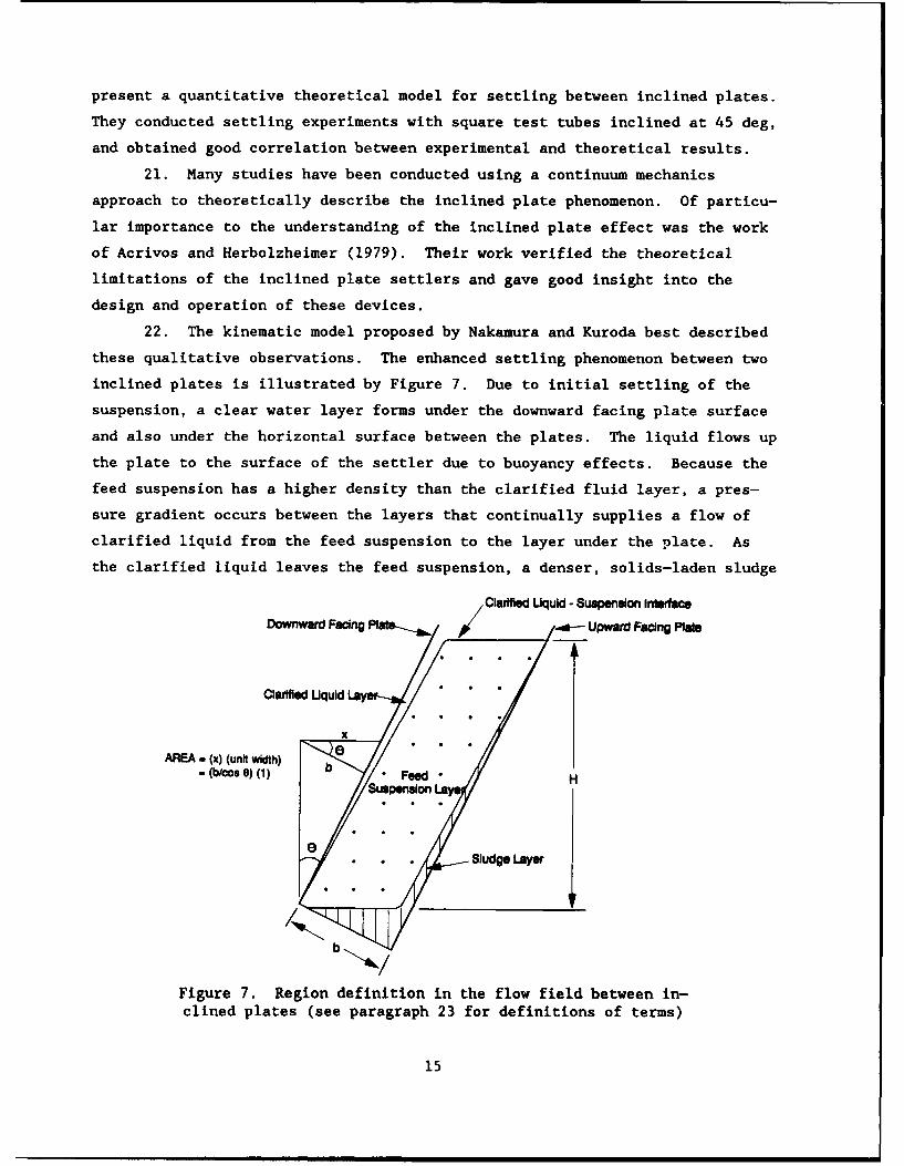
22. The kinematic model proposed by Nakamura and Kuroda best described
these qualitative observations. The enhanced settling phenomenon between two
inclined plates is illustrated by Figure 7. Due to initial settling of the
suspension, a clear water layer forms under the downward facing plate surface
and also under the horizontal surface between the plates. The liquid flows up
the plate to the surface of the settler due to buoyancy effects. Because the
feed suspension has a higher density than the clarified fluid layer, a pres-
sure gradient occurs between the layers that continually supplies a flow of
clarified liquid from the feed suspension to the layer under the plate. As
the clarified liquid leaves the feed suspension, a denser, solids-laden sludge
Clarified Uquid - Suspenslon InterfaCe
Downward Facing Paraap / od n Upward Facing Plars
Clarified Uquld Lay
X
AREA - (x) (unit width) G
15
•~~~ (b00 0) (1 Feedmn Hnm•H ••
layer forms on the upward-facing plate surface and slides down to the bottom
of the settler.
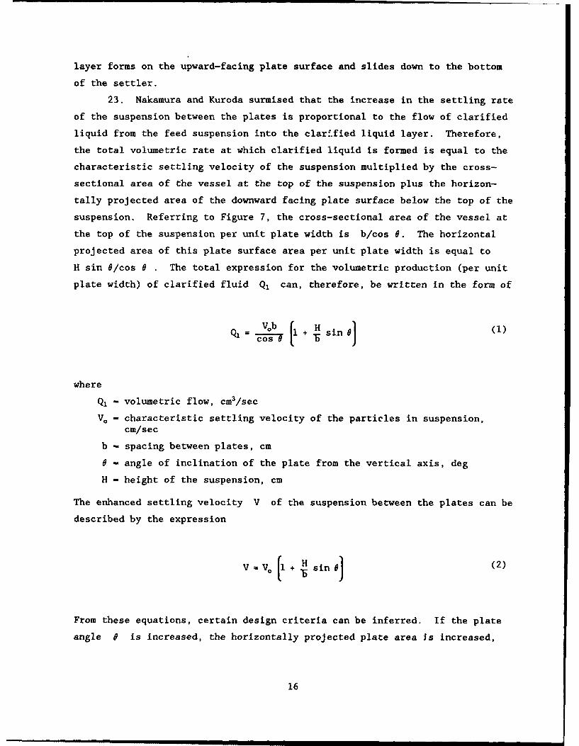
23. Nakamura and Kuroda surmised that the increase in the settling rate
of the suspension between the plates is proportional to the flow of clarified
liquid from the feed suspension into the clarified liquid layer. Therefore,
the total volumetric rate at which clarified liquid is formed is equal to the
characteristic settling velocity of the suspension multiplied by the cross-
sectional area of the vessel at the top of the suspension plus the horizon-
tally projected area of the downward facing plate surface below the top of the
suspension. Referring to Figure 7, the cross-sectional area of the vessel at
the top of the suspension per unit plate width is b/cos 6. The horizontal
projected area of this plate surface area per unit plate width is equal to
H sin O/cos 0 . The total expression for the volumetric production (per unit
plate width) of clarified fluid Q, can, therefore, be written in the form of
S= b + H sin 0 (1)
where
Q, - volumetric flow, cm3/sec
V0 - characteristic settling velocity of the particles in suspension,cm/sec
b - spacing between plates, cm
8 - angle of inclination of the plate from the vertical axis, deg
H - height of the suspension, cm
The enhanced settling velocity V of the suspension between the plates can be
described by the expression
V -V. (+ H~ sin ] (2)
From these equations, certain design criteria can be inferred. If the plate
angle 0 is increased, the horizontally projected plate area Is increased,
16
thus increasing the overall settling rate. Also if the plate spacing b is
decreased, the settling rate is increased.
24. The work of Acrivos and Herbolzheimer (1979) theoretically verified
that Equation 2 satisfactorily predicts the settling rate between the plates
provided certain criteria are satisfied. The suspension must be well dis-
persed and have a uniform concentration distribution. The particle Reynolds
number must be small, and most importantly, the interface between the clear
fluid layer and the feed suspension layer must remain stable.
25. The described inclined plate settler in the model hopper operates
with countercurrent flow (Leung and Probstein 1983). For countercurrent flow,
the feed slurry is input into the model hopper close to the bottom of the
hopper. The feed slurry then flows up the inclined plate channel in the oppo-
site direction to the falling sludge. The flow of the feed slurry in the
opposite direction to the falling sludge creates shear stresses that act
against the gravitational force pulling the sludge layer down the upward-
facing plate surface. If the angle of inclination of the plate from the
vertical axis is too great, the movement of the sludge layer down the upward-
facing plate may become inhibited, thus reducing the efficiency of the
settler.
26. Herbolzheimer (1983) investigated the stability of the boundary
layer between the clarified liquid and the feed suspension. He found that the
boundary layer was more stable at large angles of inclination and lower sus-
pension concentrations. At small plate angles (<30 deg), waves began to form
at the interface of the clear liquid and feed suspension that, upon breaking,
caused some entrainment of sediment into the clarified liquid stream, thus
reducing the efficiency of the settler.
Model Hopper Test Configuration
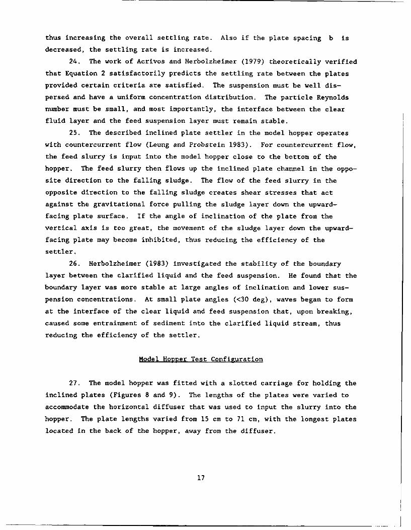
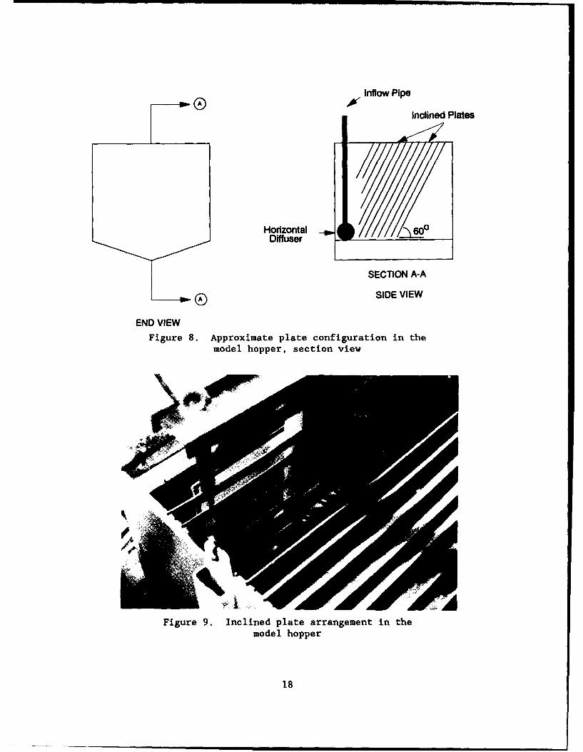
27. The model hopper was fitted with a slotted carriage for holding the
inclined plates (Figures 8 and 9). The lengths of the plates were varied to
accommodate the horizontal diffuser that was used to input the slurry into the
hopper. The plate lengths varied from 15 cm to 71 cm, with the longest plates
located in the back of the hopper, away from the diffuser.
17
Inflow Pipe
Inclined Plates
Horizontal 6&Diffuser
SECTION A-A
SIDE VIEW
END VIEW
Figure 8. Approximate plate configuration in themodel hopper, section view
Figure 9. Inclined plate arrangement in themodel hopper
18
Test Results and Discussion
Clay slurry tests
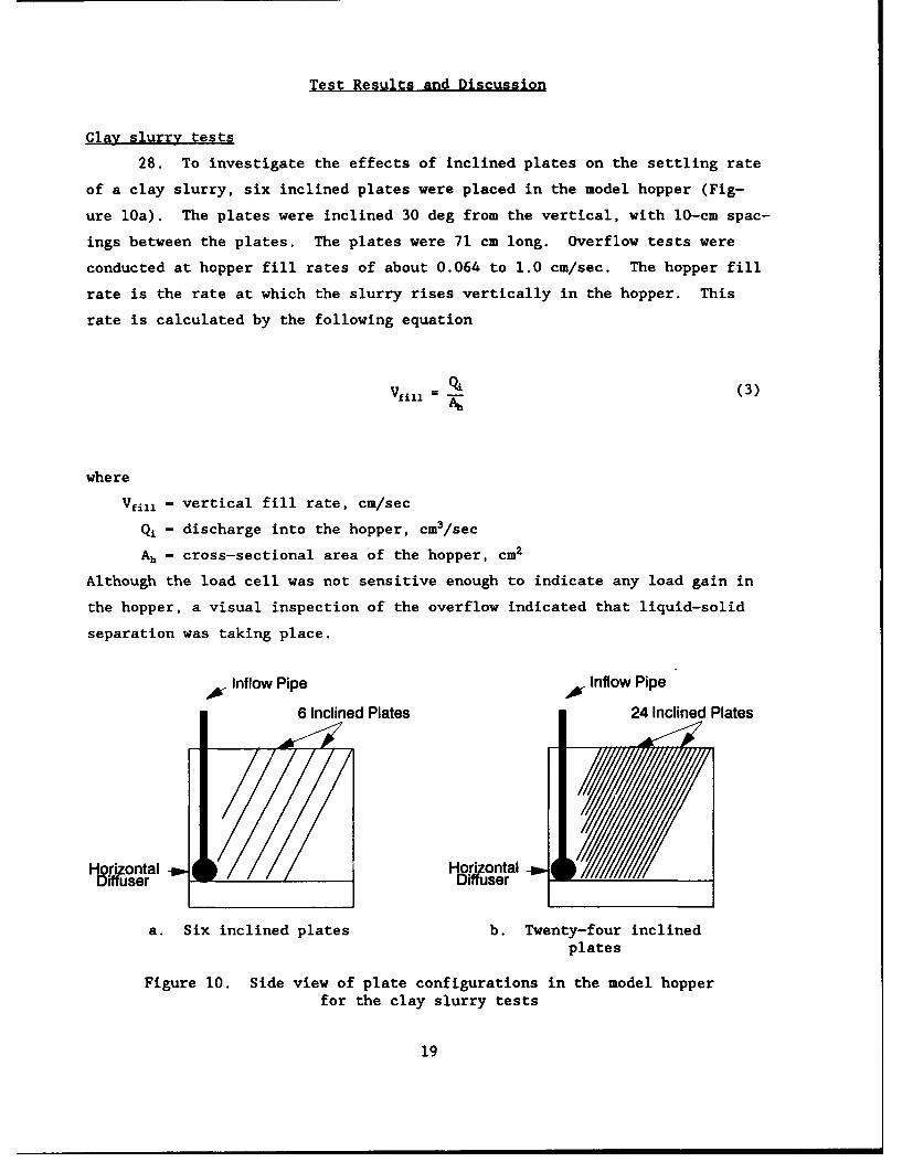
28. To investigate the effects of inclined plates on the settling rate
of a clay slurry, six inclined plates were placed in the model hopper (Fig-
ure 10a). The plates were inclined 30 deg from the vertical, with 10-cm spac-
ings between the plates. The plates were 71 cm long. Overflow tests were
conducted at hopper fill rates of about 0.064 to 1.0 cm/sec. The hopper fill
rate is the rate at which the slurry rises vertically in the hopper. This
rate is calculated by the following equation
'411 . (3)
where
Vfi.1 - vertical fill rate, cm/sec
Qj - discharge into the hopper, cm3/sec
S- cross-sectional area of the hopper, cm2
Although the load cell was not sensitive enough to indicate any load gain in
the hopper, a visual inspection of the overflow indicated that liquid-solid
separation was taking place.
1W Inflow Pipe Inflow Pipe
6 Inclined Plates 24 Inclined Plates
I-ji ontal %H&A ontal -go
a. Six inclined plates b. Twenty-four inclinedplates
Figure 10. Side view of plate configurations in the model hopperfor the clay slurry tests
19
29. Further tests were conducted with 24 inclined plates in the hopper
(Figure 10b). This plate arrangement resulted in a spacing of one plate per
2.54 cm. Vertical profile density samples taken during these tests indicated
that at the low hopper fill rate (0.064 cm/sec), up to 15 percent of the feed
solids were being retained in the hopper during overflow. At a higher, more
practical range of fill rates, around 0.25-1.0 cm/sec, the density samples
indicated that no feed solids were accumulating in the hopper.
30. The data from the load cell were erratic during these initial
tests. The stated accuracy of the load cell is 1 percent of full scale, or
±9 kg for these test purposes. It was decided that because of the insensitiv-
ity of the load cell, only the density of the hopper overflow would be sampled
in subsequent tests. By recording the density of the overflow as a function
of time, a mass balance was performed on the hopper to determine the amount of
feed solids retained during overflow.
Mass balance calculations
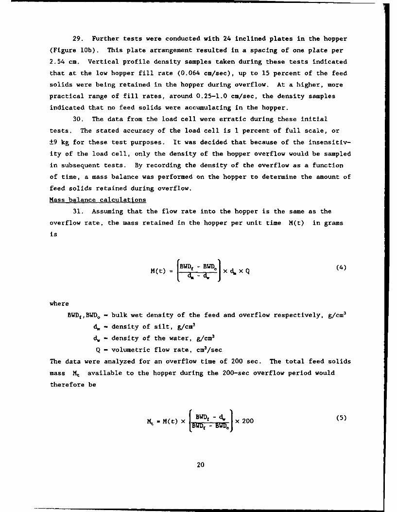
31. Assuming that the flow rate into the hopper is the same as the
overflow rate, the mass retained in the hopper per unit time M(t) in grams
is
H(t) = BWDf -BWDc ) Xd. xQ (4)
where
BWDf,BWDo - bulk wet density of the feed and overflow respectively, g/cm3
d, - density of silt, g/cm3
d, - density of the water, g/cm3
Q - volumetric flow rate, cm3/sec
The data were analyzed for an overflow time of 200 sec. The total feed solids
mass Mt available to the hopper during the 200-sec overflow period would
therefore be
Mt= M(t) x BWDf -dw) x 200 (5)
20
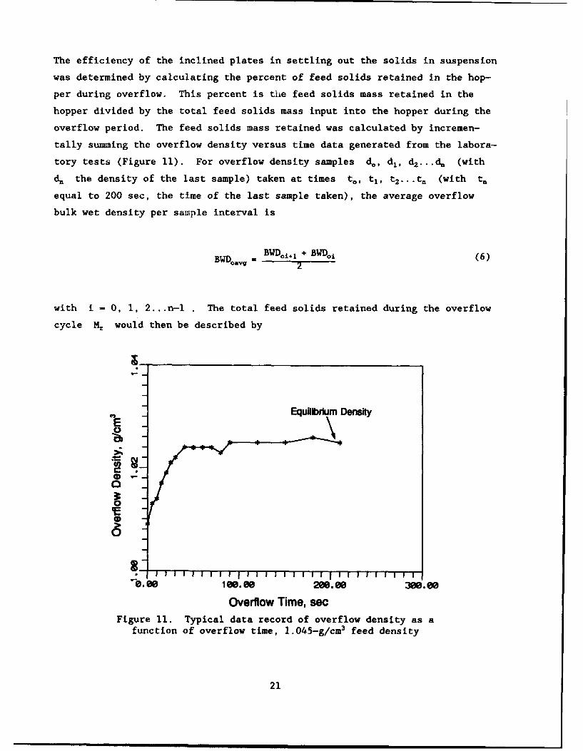
The efficiency of the inclined plates in settling out the solids in suspension
was determined by calculating the percent of feed solids retained in the hop-
per during overflow. This percent is the feed solids mass retained in the
hopper divided by the total feed solids mass input into the hopper during the
overflow period. The feed solids mass retained was calculated by incremen-
tally summing the overflow density versus time data generated from the labora-
tory tests (Figure 11). For overflow density samples d., dj, d2...d. (with
d. the density of the last sample) taken at times t., t1 , t 2 ... t (with t.
equal to 200 sec, the time of the last sample taken), the average overflow
bulk wet density per sample interval is
BWD.Ayg = BWDoi, 2 + BWD0 j (6)2
with i - 0, 1, 2.. .n- . The total feed solids retained during the overflow
cycle Mr would then be described by
Equ~ibrm Density
r--ý06 0.0200.00 380.88
Overflow Time, secFigure 11. Typical data record of overflow density as a
function of overflow time, 1.045-g/cm3 feed density
21
~(BWDg - BWD0.. j x Ci x Q X t1. - 1i (7)
This equation represents the total inflow solids mass accumulated in the hop-
per over a 200-sec overflow cycle. The percentage of retained solids P, in
the hopper would therefore be calculated by
S- Mx 100 (8)
Silt slurry tests
32. Silt slurry tests were conducted with and without plates in the
model hopper. Tests were conducted without plates for baseline data on the
settling rate of the suspended sediments due to the effect of gravity. Tests
were conducted for both 24- and 12-plate arrangements. The 24-plate arrange-
ment had a plate spacing of 2.54 cm, while the 12-plate arrangement had a
plate spacing of 5.08 cm. The hopper fill rates were varied within the range
of about 0.064-1.0 cm/sec. The overflow was sampled between the 71-cm-length
plates located in the back of the hopper. The following test description and
results are based on flow through the 71-cm plates.
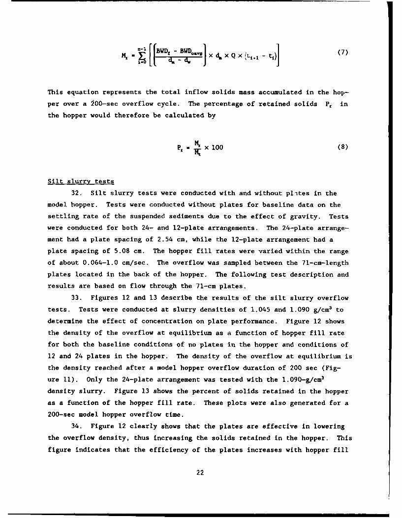
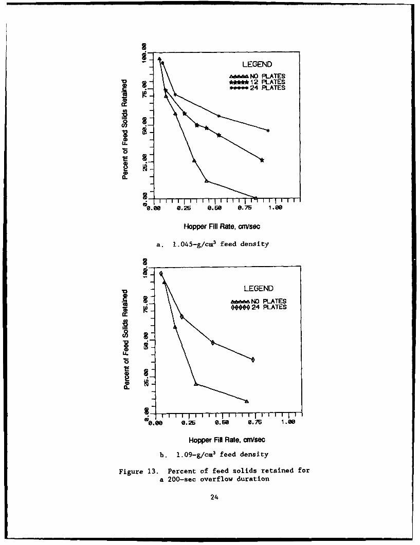
33. Figures 12 and 13 describe the results of the silt slurry overflow
tests. Tests were conducted at slurry densities of 1.045 and 1.090 g/cm3 to
determine the effect of concentration on plate performance. Figure 12 shows
the density of the overflow at equilibrium as a function of hopper fill rate
for both the baseline conditions of no plates in the hopper and conditions of
12 and 24 plates in the hopper. The density of the overflow at equilibrium is
the density reached after a model hopper overflow duration of 200 sec (Fig-
ure 11). Only the 24-plate arrangement was tested with the 1.090-g/cm3
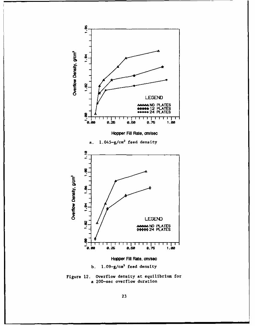
density slurry. Figure 13 shows the percent of solids retained in the hopper
as a function of the hopper fill rate. These plots were also generated for a
200-sec model hopper overflow time.
34. Figure 12 clearly shows that the plates are effective in lowering
the overflow density, thus increasing the solids retained in the hopper. This
figure indicates that the efficiency of the plates increases with hopper fill
22
LEGEND
&&&NO PLATES** 12 PLATES*+* 24 PLATES
"0.00 6.25 6.56 0.76 1.66
Hopper Fill Rate, cm/sec
a. 1.045-g/cm3 feed density
- *924 PLATES
r7--"6.66 6.25 6.66 6.75 1.66
Hopper Fill Rate, cm/sec
b. 1.09-g/cm3 feed density
Figure 12. Overflow density at equilibrium fora 200-sec overflow duration
23
LEGEND- NO PLATES
0 -**** 12 PLATES.- 24 PLATES
32
0 -
3--'.00 0.25 0.60 0.75 1.00
Hopper Fill Rate, cm/sec
a. 1.045-g/cM3 feed density
V LEGEND
1,,3 NO PLATESS- • 24 PLATES
cc
, F -I I i ' I I I iI I I I I I I 1 1 7
o.88 0.26 8.6. 0.75 1.08
Hopper Fill Rate, cm/sec
b. 1.09-g/cm3 feed density
Figure 13. Percent of feed solids retained fora 200-sec overflow duration
24
rates greater than 0.25 cm/sec, becoming constant at about 0.50 cm/sec. This
efficiency is defined by the change in density that occurs between the curves
representing conditions of no plates and 24 or 12 plates in the hopper. The
plots of percent solids retained as a function of hopper fill rate (Figure 13)
indicate that, for the 1.045-g/cm3 feed density, the 24-plate arrangement with
2.54-cm plate spacings resulted in 50 percent more feed solids retained than
for the case of no plates in the hopper. The 12-plate arrangement with
5.08-cm plate spacings resulted in about 25 percent more feed solids retained.
This percentage increase was constant for hopper fill rates of about 0.50 to
1.0 cm/sec. With an increase in feed density to 1.09 g/cm3, the 24-plate
arrangement resulted in about a 30 percent increase in feed solids retained in
the hopper. This percentage increase was constant for hopper fill rates of
about 0.50 to 0.80 cm/sec.
35. These results are based on all of the slurry passing between the
plates with the maximum length of 71 cm. In prototype applications, a portion
of the flow would not pass between plates because of space limitations in the
hopper. This would result in a somewhat reduced solids retention efficiency
in the hopper.
36. The inclined plates in the model hopper occupied only a small por-
tion of the available volume, but added substantial weight to the hopper. For
a practical application, it would be necessary to fabricate the plates out of
low-density plastics or composite materials, such as graphite-epoxy, that
possess the material strength and abrasion resistance to survive in a dredge
hopper environment.
37. By increasing the solids content of the slurry by a factor of two,
the percent of feed solids retained in the hopper was reduced from 50 to
30 percent. Because of this decrease in plate efficiency with increasing con-
centration, the inclined plate concept with this configuration may be viable
only for low-density slurries (< 1.1 g/cm3 ).
Dimensional Scalina of the Inclined Plate Settler
38. The equation for describing the volumetric production of clarified
fluid due to the presence of inclined plates was earlier derived as
Equation 1:
25
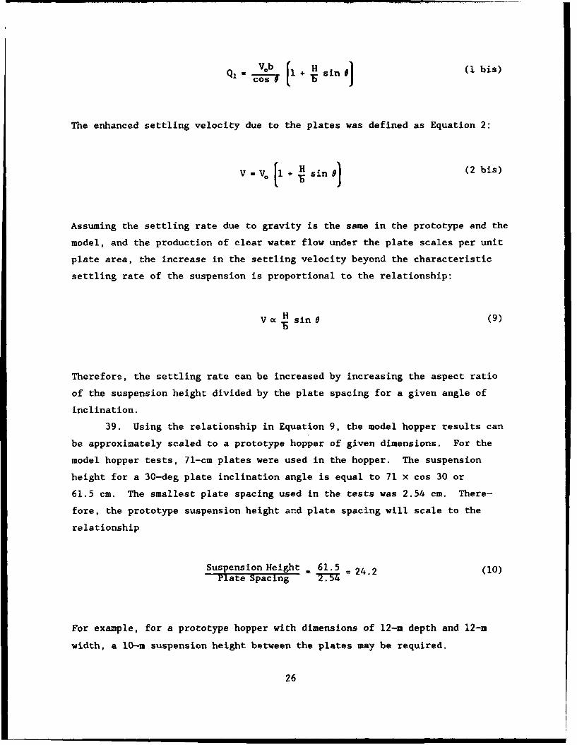
Q2 0 + H sin 0 (i bis)Cos e e
The enhanced settling velocity due to the plates was defined as Equation 2:
[1- . + H~ sin ) (2 bs
Assuming the settling rate due to gravity is the same in the prototype and the
model, and the production of clear water flow under the plate scales per unit
plate area, the increase in the settling velocity beyond the characteristic
settling rate of the suspension is proportional to the relationship:
V Hc sin 0 (9)
Therefore, the settling rate can be increased by increasing the aspect ratio
of the suspension height divided by the plate spacing for a given angle of
inclination.
39. Using the relationship in Equation 9, the model hopper results can
be approximately scaled to a prototype hopper of given dimensions. For the
model hopper tests, 71-cm plates were used in the hopper. The suspension
height for a 30-deg plate inclination angle is equal to 71 x cos 30 or
61.5 cm. The smallest plate spacing used in the tests was 2.54 cm. There-
fore, the prototype suspension height and plate spacing will scale to the
relationship
Suspension Height 61.5 = 24.2 (10)Plate Spacing 2T37 "
For example, for a prototype hopper with dimensions of 12-m depth and 12-M
width, a 10-m suspension height between the plates may be required.
26

Therefore, the corresponding plate spacing for the hopper would be 10/24.2 or
0.41 m. The plate length for a 30-deg angle of inclination from the vertical
would be 10/cos 30 or 11.5 m.
40. This relationship should serve only as an approximation for initial
settler design. It was apparent from the test results that the interface
between the clarified layer and the feed suspension layer was not stable, with
sediment entrained into the clear water layer.
41. The inclined plate settler tests were performed under dynamic flow
conditions, with a steady flow of slurry into the hopper. The rate at which
the slurry rises in the hopper will directly influence the settling rate of
fine-grained sediments in the suspension. In prototype dredge hoppers, the
rate at which the slurry rises in the hopper can range from 0.60 to
1.0 cm/sec. The combination of the drag and buoyancy forces exerted on the
fine sediment particles from the upward flow of the slurry at these rates is
sufficient to negate particle settlement, and subsequently cause the sediments
to leave the hopper with the overflow.
42. For example, consider an ideal hopper environment with a laminar
flow field containing idealized spherical sediments that settle as the hopper
fills at a given rate. The ability of the sediments to settle in this envi-
ronment can be estimated by performing a force balance on the sediment parti-
cle. The sum of the forces acting on the particle is described by
XF = F, - Fb - Fd (11)
where
F. - force due to the weight of the sediment particle (gravity)
Fb - buoyancy force (weight of fluid displaced by the particle volume)
Fd - drag force (viscous effects) acting on the particle
For the case of hopper fill rates within the range of 0.60 to 1.0 cm/sec, the
particle Reynolds number would be less than 1; therefore this would be
described as creeping flow, or flow in which the flow about the particle is
completely viscous. For this type of flow, the friction drag is given by
Stokes law as
27
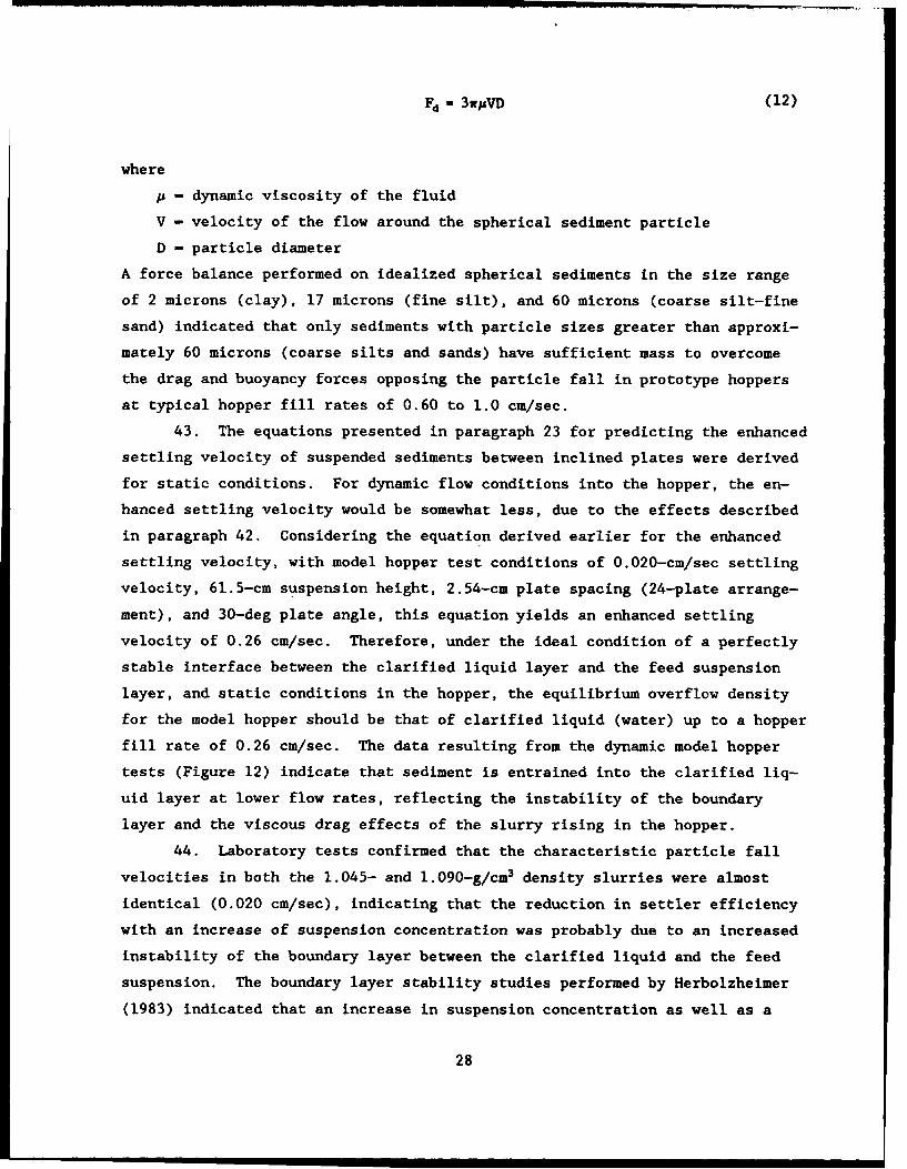
Fd 3wuVD (12)
where
p - dynamic viscosity of the fluid
V - velocity of the flow around the spherical sediment particle
D - particle diameter
A force balance performed on idealized spherical sediments in the size range
of 2 microns (clay), 17 microns (fine silt), and 60 microns (coarse silt-fine
sand) indicated that only sediments with particle sizes greater than approxi-
mately 60 microns (coarse silts and sands) have sufficient mass to overcome
the drag and buoyancy forces opposing the particle fall in prototype hoppers
at typical hopper fill rates of 0.60 to 1.0 cm/sec.
43. The equations presented in paragraph 23 for predicting the enhanced
settling velocity of suspended sediments between inclined plates were derived
for static conditions. For dynamic flow conditions into the hopper, the en-
hanced settling velocity would be somewhat less, due to the effects described
in paragraph 42. Considering the equation derived earlier for the enhanced
settling velocity, with model hopper test conditions of 0.020-cm/sec settling
velocity, 61.5-cm suspension height, 2.54-cm plate spacing (24-plate arrange-
ment), and 30-deg plate angle, this equation yields an enhanced settling
velocity of 0.26 cm/sec. Therefore, under the ideal condition of a perfectly
stable interface between the clarified liquid layer and the feed suspension
layer, and static conditions in the hopper, the equilibrium overflow density
for the model hopper should be that of clarified liquid (water) up to a hopper
fill rate of 0.26 cm/sec. The data resulting from the dynamic model hopper
tests (Figure 12) indicate that sediment is entrained into the clarified liq-
uid layer at lower flow rates, reflecting the instability of the boundary
layer and the viscous drag effects of the slurry rising in the hopper.
44. Laboratory tests confirmed that the characteristic particle fall
velocities in both the 1.045- and 1.090-g/cm3 density slurries were almost
identical (0.020 cm/sec), indicating that the reduction in settler efficiency
with an increase of suspension concentration was probably due to an increased
instability of the boundary layer between the clarified liquid and the feed
suspension. The boundary layer stability studies performed by Herbolzheimer
(1983) indicated that an increase in suspension concentration as well as a
28

small plate angle resulted in wave formation and mixing in the boundary layer.
Because of the countercurrent operation of the model hopper inclined plate
settler, the maximum allowable angle of inclination of the plates was 30 deg
from the vertical axis. This may prove to be a major limitation for an
inclined plate settler design in dredge hoppers operating in a countercurrent
mode.
Analysis and Discussion of Test Results
45. The following points are based on the inclined plate test results:
a. For clay suspensions, an inclined plate spacing of one plateper 2.54 cm in the hopper increased the percent of feed solidsretained in the hopper by only about 15 percent at an impracti-cally low hopper fill rate of 0.064 cm/sec.
b. Test results indicated that the overall efficiency of the in-clined plates decreased with increased slurry density, in-creased with decreased plate separation, and increased withdecreased flow rate.
c. The plates were more efficient at the higher hopper fill rates(> 0.25 cm/sec) for the silt slurry than for the clay slurry.
d. For hopper fill rates in the range of 0.25 to 1.0 cm/sec with a1.045-g/cm 3 silt slurry and an inclined plate spacing of oneplate per 2.54 cm, 50 percent more feed solids were retainedthan when no plates were present in the hopper. By doublingthe plate spacing to 5.08 cm, the percent solids mass retaineddropped to about 25 percei.t, or approximately one-half.
e. When the silt slurry density was increased from 1.045 to1.090 g/cm3 , a 20 percent reduction in the solids retained inthe hopper occurred over a 200-sec overflow time for a platespacing of one plate per 2.54 cm in the hopper.
f. At the one plate per 2.54-cm spacing, the plates occupied verylittle volume, but the total weight added to the hopper wassubstantial.
46. The model hopper tests confirmed that the inclined plate settler
technique may be viable for suspended sediments within the silt size range.
The implementation of inclined plates in dredge hoppers is constrained not
only by the type of sediments dredged, but also by the available volume in the
hopper for insertion of the inclined plates. Host hoppers have numerous
obstructions that would limit the size and number of plates that could be
installed.
47. The equation presented for the prediction of enhanced settling
29

velocity in inclined plate settlers serves as a good guideline for the initial
design of an inclined plate arrangement for dredge hoppers or other special-
ized applications. The model hopper experiments confirmed that settler effi-
ciency is directly related to the ratio of the suspension height to the
inclined plate spacing.
48. The laboratory tests described were not designed solely to predict
the performance of plate settlers in prototype applications, but more impor-
tantly, to verify that the design equations can serve as an approximate guide
for developing a prototype dredge hopper plate settler. Further tests should
be conducted with model plate settlers that operate in a continuous batch set-
tling mode. This would involve much longer overflow times than the 200-sec
duration used in these tests. These tests would provide data on the long
duration overflow efficiency of the plate settler and give a better idea of
the practicality of the use of plate settlers for prototype dredge hopper
applications.
49. Although metal inclined plates installed in a prototype dredge
hopper would add substantial weight to the dredge, low-density, high-strength
plates fabricated from composite materials could reduce the unit weight by
over 50 percent. Further studies of plate boundary layer behavior should be
undertaken to further increase the efficiency of the settler.
30
PART V: CENTRIFUGAL SOLIDS CONCENTRATOR STUDY
Background
50. This part of the study to increase dredge hopper payload was con-
ducted by the Advanced Resource Development Corporation (ARD), Columbia, MD.
ARD has been working independently for the last several years developing and
applying a solids concentrator for sludge removal operations. The sludge
removal concept involves the periodic removal of solids accumulated within
tanks or sumps at industrial facilities using a portable separator system.
This system has been previously tested using high-loading coarse fractions
similar to sand. Low-loading fractions such as silt and clay have not been
tested. The purpose of these tests was to apply this concept to the
concentration of fine-grained dredged material.
Theory of Testing Program and ADproach
51. The solids concentrator operates by passing a feed stream of slurry
through a series of baffles or slots within a chamber. The baffles impart a
vortex motion to the slurry and accelerate the heavier fractions of the sedi-
ment slurry to the outside of the vortex. These heavier fractions form a
concentrated sludge and are removed in the underflow while the remaining
effluent, containing less sediment, flows out as the overflow. The solids
concentrator works in principle much like the hydrocyclone devices discussed
in a previous section of this report.
52. Two series of tests were conducted. Small-scale testing was per-
formed to determine solids concentration performance at both small-scale and
low flow rates (38-57 1 per minute). Large-scale testing was performed to
determine solids concentration performance at a larger scale and higher flow
rates (757-1,514 1 per minute) with correspondingly larger equipment of simi-
lar design. Sediment mixtures were predetermined and used in both series of
tests for comparison.
Materials Used in the Tests
53. The materials for the tests were carefully selected to represent
31
sediments encountered during the dredging of fine-grained sediments. Actual
field samples were not desirable because of the cost involved in obtaining
them and the nonrepeatability of tests when using them. The desired mixture
was not commercially available and therefore was prepared onsite by the
contractor.
54. Three materials were mixed in various concentrations for use in the
tests. Two types of silica sand and a very fine clay material were used. The
sand materials were Berkeley sand (85 percent passing No. 325 sieve) and Gore
sand (93 percent between No. 100 and No. 30 sieves). The clay material is
commercially known as Red Art Clay and has a high illite content. The mixture
desired for the tests was 12.5 percent solids by weight and included 0.25 per-
cent salt. The three mixtures used in the tests are given in the following
tabulation:
PercentTest Percent Berkeley Percent
Sediment Gore Sand Sand Red Art Clay
A 20 0 80
B 20 20 60
C 20 60 20
Small-Scale Tests
55. These tests were of the batch type, with a premixed sediment proc-
essed in a predetermined time. Initial small-scale tests determined the
minimum concentrator flow rates required to pick up the sediments from the
bottom of the test tank and entrain them into the inflow stream. The
established test flow rates used were 37 and 42 1 per minute.
56. The approximate test configuration is diagrammed in Figure 14. The
solids content of the slurry accounted for 12.5 percent of the mixed slurry by
weight, and was distributed evenly across the bottom of the tank. The mixture
was allowed to settle for a period of not less than 30 days to ensure a set-
tled test bed. After this waiting period, the small-scale tests were begun.
The equipment was operated for 3 min with samples collected every 2 min. The
mixture criteria and data gathered from the small-scale tests were used to
establish the methods and testing procedures for the large-scale test.
32

Overflow Clarified Liquid
SolidsConcentratot
Slurry Feed StreamMixture.0- Baffles
Underfiow
Solids Collection Bin
Figure 14. Solids concentrator test configuration
Large-Scale Tests
57. The final phase of testing employed much larger quantities of
slurry and a much larger capacity solids concentrator. Test sediment mate-
rial A was used (paragraph 54). The large-scale test configu.ation was very
similar to the previous configuration used for the small-scale tests with the
exception of scale (flow rates were increased by 20 to 40 times).
58. The system used for the large-scale tests was a commercially avail-
able solids separation unit normally used for separating solids from process
waste streams at manufacturing plants or from irrigation systems (Figure 15).
The two-stage system operated at flow rates of 757, 1,136, and 1,514 1 per
minute, compared to a large hopper dredge that may have pumping rates on the
order of 113,562 1 per minute. The unit was rated to remove over 98 percent
by weight of sand-sized solids from the slurry stream. A more complete
33

Figure 15. The ARD solids concentrator setup
description of the equipment is contained in Silverman, Thomas, and Strem.*
Test Results and Discussion
59. There were no distinct differences in the test results between the
three types of sediments (A, B, and C) in the small-scale tests; therefore,
only sediment A was used in the large-scale tests.
60. Several parameters were devised to evaluate test results and rate
the performance of the concentrator. only one of the parameters, concentra-
tion index (CI), will be described and summarized here. The concentration
index is defined as
CI (underflow concentration by weight _ 1) X 100 (13)feed concentration by weight Je
The test results, along with the concentration index, are presented in Table 1.
dE. B. Silverman, M. Thomas, and R. Strem. 1989 (Dec). "Fine-Grained
Sediment Separation Using A High Efficiency Solids Concentrator," preparedfor US Army Engineer Waterways Experiment Station, Vicksburg, MS, underContract Number DACW39-89-C-0018, by the Advanced Resource DevelopmentCorporation, Columbia, MD.
34
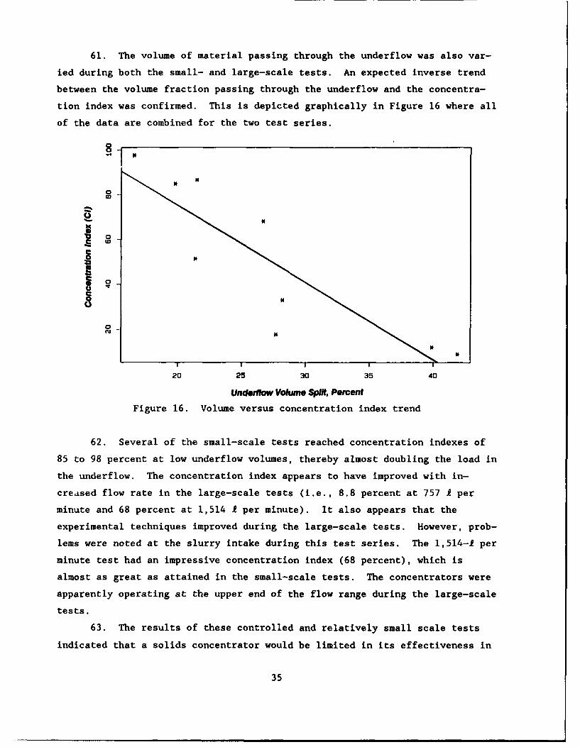
61. The volume of material passing through the underflow was also var-
ied during both the small- and large-scale tests. An expected inverse trend
between the volume fraction passing through the underflow and the concentra-
tion index was confirmed. This is depicted graphically in Figure 16 where all
of the data are combined for the two test series.
0
0
S
X
.~0
0
0
20 25 30 35 40
Undwflow Volume Split, Percent
Figure 16. Volume versus concentration index trend
62. Several of the small-scale tests reached concentration indexes of
85 to 98 percent at low underflow volumes, thereby almost doubling the load in
the underflow. The concentration index appears to have improved with in-
creased flow rate in the large-scale tests (i.e., 8.8 percent at 757 1 per
minute and 68 percent at 1,514 2 per minute). It also appears that the
experimental techniques improved during the large-scale tests. However, prob-
lems were noted at the slurry intake during this test series. The 1,514-1 per
minute test had an impressive concentration index (68 percent), which is
almost as great as attained in the small-scale tests. The concentrators were
apparently operating at the upper end of the flow range during the large-scale
tests.
63. The results of these controlled and relatively small scale tests
indicated that a solids concentrator would be limited in its effectiveness in
35

the dredging of relatively fine grained sediments. The potential benefits of
large-scale field testing of the solids concentrator under simulated dredging
conditions were evaluated. The evaluation concluded that the increased weight
of the dredge when fitted with the solids concentrator device would not be
cost effective. However, the technique may prove to be a useful tool in
small-scale operations such as the cleanup of small harbors or the removal of
subaqueous hazardous material from contaminated sites. It appears that the
concentrator method could also be beneficial in confined disposal operations
where concentration of the sediments would reduce the required site volume.
36
PART VI: CONCLUSIONS AND RECOMMENDATIONS
Conclusions
64. Laboratory testing has indicated that the inclined plate concept
and the centrifugal solids concentrator techniques for increasing solids re-
tention in the dredging of fine-grained sediments have limited potential for
prototype hopper dredge application.
65. The following conclusions are based on the results of controlled
tests performed at the WES model hopper bin facility and with the centrifugal
solids concentrator by the ARD Corporation:
a. Hydrocyclones and diffuser configurations did not indicate anysignificant increase in fine-grained solids retention.
b. The inclined plate concept tests provided initial design param-eters for developing large-scale inclined plate settlers.
c. The centrifugal solids concentrator tests performed by the ARDCorporation indicated a limited usefulness in removing fine-grained materials from a slurry.
d. Although these initial laboratory evaluations suggest that themethods tested are not presently economically justifiable whenconsidering the additional weight and the extent of modifica-tions required to retrofit an existing hopper dredge, advancesin the design and operation of the inclined plate settler andsolids concentrator may lead to cost-efficient prototypeapplications.
Recommendations
66. The inclined plate concept and the centrifugal solids concentrator
techniques may be applicable to upland disposal operations, which require that
suspended solias be removed from confined disposal site effluent. The use of
inclined plates in settling basins would reduce the settling basin surface
area requirement, resulting in a more space-efficient batch settling opera-
tion. The fabrication of inclined plates with low-density, high-strength
composite materials can reduce the unit weight by 50 percent over a conven-
tional metal design. Advances in boundary layer studies of the inclined plate
effect coule result in even higher efficiencies than reported in this publi-
cation. More research and testing are needed to further define the optimum
operating conditions of these devices and other beneficial applications in the
areas of contaminated material removal from disposal site effluent. With this
37

type of installation, the size and weight factors would not be as critical as
they exist on an operational hopper dredge. Tandem designs using a solids
concentrator device in series with an inclined plate settling basin may be the
most effective method for removing a high percentage of suspended materials in
the effluent.
38
BIBLIOGRAPHY
Acrivos, Andreas, and Herbolzheimer, Eric. 1979. "Enhanced Sedimentation inSettling Tanks with Inclined Walls," Journal of Fluid Mechanics, Vol 92,Part 3, pp 435-457.
Boycott, A. E. 1920. "Sedimentation of Blood Corpuscles," Nature. Vol 104,p 532.
Herbolzheimer, Eric. 1983. "Stability of the Flow During Sedimentation in
Inclined Channels," Journal of Physical Fluids. Vol 26, No. 8, pp 2043-2053.
Leung, Woon-Fong, and Probstein, Ronald F. 1983. "Lamella and Tube Settlers:1. Model and Operation," Industrial Design and Engineering Chemistry ProcessDesign and Development. Vol 22, No. 1, pp 58-67.
Nakamura, H., and Kuroda, K. 1937. Keiio Journal of Medicine. Vol 8, p 256.
Palermo, M. R., and Randall, R. E. 1990 (Oct). "Practices and Problems Asso-ciated with Economic Loading and Overflow of Dredge Hoppers and Scows," Tech-nical Report DRP-90-1, US Army Engineer Waterways Experiment Station.Vicksburg, MS.
Priede, N. 1990 (May). "Restoring Water Quality by Removing and DewateringSediment," International Dredging Review. Vol. 9, No. 5, pp 10-12.
Scott, S. H. 1990 (Nov). "An Inclined-Plate Technique for Increasing theSettling Rate of Fine-Grained Sediments in Hopper Bins," TechnicalNote DRP-3-04, US Army Engineer Waterways Experiment Station, Vicksburg, MS.
Tiederman, W. G., and Reischman, M. M. 1973 (July). "Feasibility Study ofHydrocyclone Systems for Dredge Operations," Contract Report D-73-1, preparedfor US Army Engineer Waterways Experiment Station, Vicksburg, MS, under Con-tract Number DACW39-72-C-0050 by the Office of Engineeriilg Research, OklahomaState University, Stillwater, OK.
Zahavi, Eli, and Rubin, Eliezer. 1975. "Settling of Solid Suspensions Underand Between Inclined Surfaces," Industrial Design and Engineering ChemistryProcess Design and Development. Vol 14, No. 1, pp 34-44.
39

Table 1
Summary of Test Results
Flow ConcentrationTest Rate Sediment Percent Solids by Weight CI
Series I/mm Mixture Feed Overflo Underflow percent
Small 37 A 12.5 8.9 16.6 32.837 B 12.5 6.5 14.0 12.037 C 12.5 8.0 23.1 84.8
Small 42 A 12.5 7.1 23.3 86.442 B 12.5 7.7 24.7 97.642 C 12.5 8.3 18.9 51.2
Large 757 A 12.5 NA* 13.6 8.81,136 A 12.5 NA 14.7 17.61,514 A 12.5 NA 21.0 68.0
* NA - not available.
Waterways Experiment Station Cataloging-in-Publication Data
Scott, Stephen H.Laboratory testing of methods to increase hopper dredge payloads:
model hopper bin facility and centrifugal solids concentrator / by StephenH. Scott, Walter Pankow, Thad C. Pratt ; prepared for Department of theArmy, US Army Corps of Engineers ; monitored by Coastal EngineeringResearch Center, U.S. Army Engineer Waterways Experiment Station.
44 p. : ill. ; 28 cm. - (Technical report ; DRP-92-4)Includes bibliographical references.1. Dredges - Equipment and supplies. 2. Bulk solids handling. 3.
Separators (Machines) 4. Dredging spoil. I. Pankow, Waiter E. I1.Pratt, Thad C. II. United States. Army. Corps of Engineers. IV.Coastal Engineering Research Center (U.S.) V. U.S. Army EngineerWaterways Experiment Station. VI. Dredging Research Program. VII.Title. VIII. Series: Technical report (U.S. Army Engineer Waterways Ex-periment Station) ; DRP-92-4.TA7 W34 no.DRP-92-4