Embed Size (px)
Citation preview
This document was downloaded from the Penspen Integrity Virtual Library
For further information, contact Penspen Integrity:
Penspen Integrity Units 7-8
St. Peter's Wharf Newcastle upon Tyne
NE6 1TZ United Kingdom
Telephone: +44 (0)191 238 2200
Fax: +44 (0)191 275 9786 Email: [email protected]
Website: www.penspenintegrity.com
______________________________ 1 Head of Pipeline Integrity - Penspen Limited 2 Senior Consultant - Penspen Limited 3 Subsea Engineering Advisor - QatarGas
IBP1033_11 THE FLEXIBLE GROUTED CLAMP - A NOVEL APPROACH
TO EMERGENCY PIPELINE REPAIR Roland Palmer-Jones1, Gordon Paterson 2,
Glenn Aldo Nespeca3
Copyright 2011, Brazilian Petroleum, Gas and Biofuels Institute - IBP This Technical Paper was prepared for presentation at the Rio Pipeline Conference & Exposition 2011, held between September, 20-22, 2011, in Rio de Janeiro. This Technical Paper was selected for presentation by the Technical Committee of the event. The material as it is presented, does not necessarily represent Brazilian Petroleum, Gas and Biofuels Institute’ opinion or that of its Members or Representatives. Authors consent to the publication of this Technical Paper in the Rio Pipeline Conference & Exposition 2011. Abstract
The interaction of a ship’s anchor with a large diameter subsea oil or gas pipeline can cause substantial damage. Failure may be instant, recent experience indicates that a combination of the thick pipe wall, protective concrete coating and flexibility of the pipelines means that a common outcome is a combination of denting, displacement, and possibly gouging. This combination of damage is severe and methods for reliably assessing the damage are limited. Consequently there is a need to repair this type of damage quickly and effectively.
Pipeline operators keep emergency repair clamps in case of incidents. The available systems are adequate for
the repair of a leaking defect, such as those that may be caused by corrosion; however, they are usually straight and cannot readily be fitted to pipelines that have been displaced and distorted. In addition, they do not necessarily incorporate structural grouts that will support damage and prevent failure of the defect under the clamp. Engineers at Qatargas identified the ‘Flexible Grouted Clamp’ concept to address this issue, and ensure that they were in the best possible position to repair anchor damage to their large diameter gas pipelines. This concept has been developed by Penspen into a detailed design for a simple off-the-shelf modular repair system that can quickly be modified to suit a wide variety of credible damage geometries.
This paper presents the development of this design, the key components, and the benefits of this novel
approach to the emergency repair of offshore pipelines.
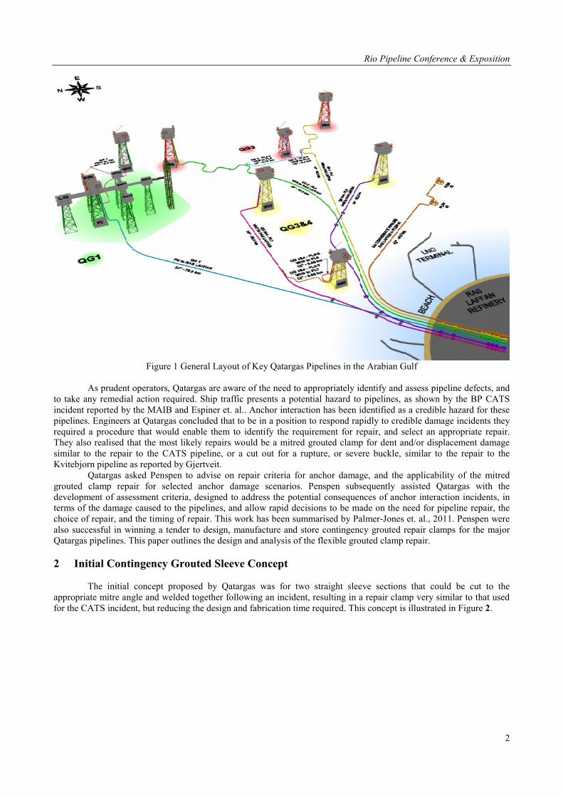
1 Introduction Qatargas Operating Company (Qatargas) operates a system of large (16inch to 42inch) diameter subsea gas and condensate pipelines in the Arabian Gulf, Figure 1. They are currently establishing an Emergency Pipeline Repair System (EPRS) for these pipelines.
Rio Pipeline Conference & Exposition
2
Figure 1 General Layout of Key Qatargas Pipelines in the Arabian Gulf
As prudent operators, Qatargas are aware of the need to appropriately identify and assess pipeline defects, and
to take any remedial action required. Ship traffic presents a potential hazard to pipelines, as shown by the BP CATS incident reported by the MAIB and Espiner et. al.. Anchor interaction has been identified as a credible hazard for these pipelines. Engineers at Qatargas concluded that to be in a position to respond rapidly to credible damage incidents they required a procedure that would enable them to identify the requirement for repair, and select an appropriate repair. They also realised that the most likely repairs would be a mitred grouted clamp for dent and/or displacement damage similar to the repair to the CATS pipeline, or a cut out for a rupture, or severe buckle, similar to the repair to the Kvitebjorn pipeline as reported by Gjertveit.
Qatargas asked Penspen to advise on repair criteria for anchor damage, and the applicability of the mitred grouted clamp repair for selected anchor damage scenarios. Penspen subsequently assisted Qatargas with the development of assessment criteria, designed to address the potential consequences of anchor interaction incidents, in terms of the damage caused to the pipelines, and allow rapid decisions to be made on the need for pipeline repair, the choice of repair, and the timing of repair. This work has been summarised by Palmer-Jones et. al., 2011. Penspen were also successful in winning a tender to design, manufacture and store contingency grouted repair clamps for the major Qatargas pipelines. This paper outlines the design and analysis of the flexible grouted clamp repair. 2 Initial Contingency Grouted Sleeve Concept
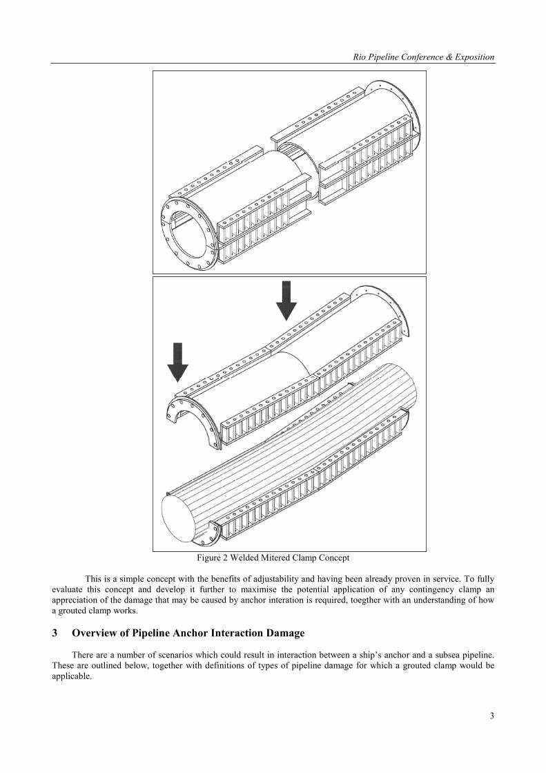
The initial concept proposed by Qatargas was for two straight sleeve sections that could be cut to the
appropriate mitre angle and welded together following an incident, resulting in a repair clamp very similar to that used for the CATS incident, but reducing the design and fabrication time required. This concept is illustrated in Figure 2.
Rio Pipeline Conference & Exposition
3
Figure 2 Welded Mitered Clamp Concept
This is a simple concept with the benefits of adjustability and having been already proven in service. To fully
evaluate this concept and develop it further to maximise the potential application of any contingency clamp an appreciation of the damage that may be caused by anchor interation is required, toegther with an understanding of how a grouted clamp works.
3 Overview of Pipeline Anchor Interaction Damage
There are a number of scenarios which could result in interaction between a ship’s anchor and a subsea pipeline. These are outlined below, together with definitions of types of pipeline damage for which a grouted clamp would be applicable.
Rio Pipeline Conference & Exposition
4
3.1 Dropped Anchor
Anchors are normally deployed when the ship has been brought to a stop by the ship’s engines. When the anchor is dropped from a ship it will probably penetrate vertically into the seabed. The depth of penetration depends on the weight and shape of the anchor, and the characteristics of the seabed soils.
When a vessel requires to anchor routinely, the ship's captain will normally inspect his sea charts to avoid obstacles and preferably choose an area assigned for anchoring. But in the event of an emergency situation this may not be the case. There is therefore the potential for the anchor to be dropped directly on to the pipeline and to damage it, resulting in a dent and, or a gouge.
3.2 Dragged Anchor Impact
Once the anchor is on the seabed, more anchor chain would normally be paid out so to that the chain will rest on the seabed. This should cause the anchor flukes to dig into the seabed when the anchor chain tightens as it begins to hold the vessel against the prevailing sea-states. The flukes gradually work down into the soil until the body of the anchor is either partly or wholly embedded in the seabed and the anchor attains its maximum holding power. If the anchor were to drag across the pipeline during this process the anchor could impact the pipeline resulting in a dent and/or gouge.
3.3 Anchor Snag and Pull Over
If an interaction occurs, an additional more sustained load may be applied to the pipeline after the anchor impact in the form of a snagging load or a pullover load as outlined in DNV RP-F107. If the anchor should snag the pipeline then there is the potential for kinetic energy of the vessel to be transferred to the pipeline, unless the anchor chain breaks. Alternatively, the anchor may initially catch on the pipeline but may then come free again as the anchor chain tightens and the anchor rotates over the pipe. This is known as a pullover, and results in a smaller load being applied to the pipeline for a shorter time.
During a pull over interaction therefore, some of the kinetic energy of the vessel and anchor may be transferred to cause denting or gouging of the pipeline, and some of the energy may be used in pulling the pipeline along the seabed, until the anchor chain breaks or the anchor pulls over the line. Depending on the loads and restraint applied to the pipeline, the interaction will cause bending of the pipeline which could lead to local buckling at the point at which the anchor pulls the line. This event could therefore result in a combination of denting, gouging, global pipeline displacement, and local buckling.
3.4 Grouted Clamp Repair Cases
For the purposes of developing a repair clamp design the potential damage incidents outlined above were
simplified to 3 cases. The potential for gouging damage was not specifically included, since damage assessment procedures require any gouging to be ground to a smooth profile. The three cases considered are outlined below.
Type 1 Damage
Pipeline dragged by a representative twin-pronged anchor, in contact with the pipeline at two points until the internal diameter of the pipeline ovalises at the points of contact and reduces the internal pipeline diameter by approximately 10%. This damage type combines pipeline global deformation and local pipeline deformation. A 10% reduction in pipeline internal diameter is considered the practical limit for successful pigging operations.
Type 2 Damage
Pipeline dragged by a representative anchor, in contact with the pipeline at one single point based on the above ovalisation criteria. This damage type combines pipeline global deformation and local pipeline deformation.
Type 3 Damage
Pipeline dented locally by a horizontal anchor impact or a dropped object impact with the dent causing an approximately 10% reduction in the pipeline ID. With this damage type no significant global pipeline deformation is considered.
Rio Pipeline Conference & Exposition
5
4 Background to Pipeline Grouted Clamp Repair
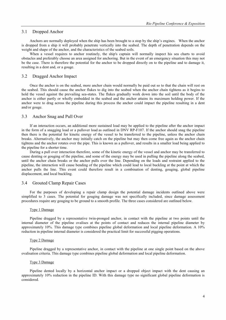
Close fitting welded sleeves are a popular repair method for onshore pipelines (Jaske et. al., 2006). Damaged areas such as dents or external corrosion are filled with a hard setting material such as an epoxy grout. Fitting a welded sleeve tightly to a damaged pipeline can be difficult. A loose fitting sleeve with the space between the damaged pipe and the welded sleeve filled with grout is easier to fit and gives the damaged pipe support. A schematic (from Corder and Hopkins, 1993) is shown in Figure 3.
Figure 3 Grout Filled Sleeve
An intensive programme of development work was carried out by British Gas Research and Technology in the
1980’s and early 1990’s (Corder and Hopkins, 1993). This research included:
• investigation by stress analysis of the behaviour of damaged pipe with and without repair; • the development of an appropriate grout and grout injection system, and • a large number of small scale and full scale tests covering a range of defects including metal loss,
cracking, denting, combined dents and gouges, and girth weld damage. A range of loads were also considered including pressure loads, fatigue cycling, and bending loads.
The principle of a grouted sleeve providing a high quality pipeline repair was proven by this programme. Grouted
sleeve repairs have since been used on a number of occasions for the repair of subsea pipelines. Grouted clamps are also commonly used to strengthen offshore structures, and extensive research has been carried
out on the performance of these repairs, as illustrated in the guidance document produced by Harwood and Shuttleworth for the UK Health and Safety Executive in 1988. It should be noted that the grouted repair clamps for offshore structures perform a different role to that of a grouted pipeline repair clamp. The repair of an offshore structure member involves the restoration of the bending and/or axial capacity of the member, whereas a pipeline repair clamp also has to restore the pressure containing capacity, which for a pipeline repair clamp is the predominant loading.
Rio Pipeline Conference & Exposition
6
Grouted sleeve repairs prevent the types of damage described above leading to pipeline failure by the following means:
• Restricting the bulging and gross plastic deformation, local to any defect, that precedes failure in
ductile pipeline material subject to internal pressure loading. • Reducing the cyclic flexing of dent features due to pressure and temperature cycling, thus preventing
the development of fatigue cracks. • Reducing axial stresses local to the pipeline defect caused by pipeline axial forces and bending
moments. • Reducing hoop stresses in the deformed pipeline caused by pressure and temperature effects. • Preventing local buckling and collapse at the defect by a combination of reducing local stresses and
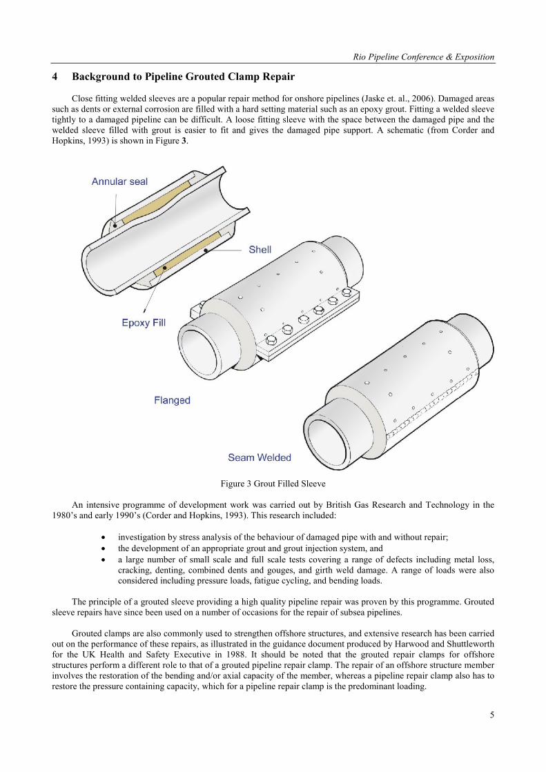
reinforcing the defect. • Overall reducing stress levels at the damaged area (see Figure 4) and improving the defect fatigue life.
Figure 4 Illustration of Stress Transfer To Sleeve From Dented Pipe
5 Design Challenges for Subsea Grouted Clamps The key design issues for a grouted clamp repair system for an offshore pipeline are:
• Length – The clamp should extend beyond the locally damaged area by at least 50% of the pipe diameter on each side. For a contingency repair system this will require an estimate of the maximum credible length of damage. Issues to consider for a subsea pipeline are anchor dimensions, and length of pipe significantly deformed (ovalised) due to the bending associated with displacement due to an anchor snag. In addition the clamp length should be sufficient on either side of the defect to allow transfer of relevant axial loads between pipeline and clamp via the grout annulus.
• Shell thickness – The clamp shell thickness should in general be similar to the pipeline wall thickness. Many pipelines have changes in wall thickness and these variations must be considered in design and an appropriate thickness selected.
• Material – The clamp material should be similar to the line pipe grade. • Annulus – The overall clamp assembly geometry selected for a particular repair must ensure the
optimum fit of the damaged pipeline within the clamp assembly. This optimum fit must ensure minimum annular gaps are maintained to ensure grout flows freely to all parts of the annulus. It must also ensure that allowable maximum gaps are not exceeded to ensure compliance with code requirements and historical test data.
Rio Pipeline Conference & Exposition
7
• Annulus end seals – the ends of the annulus must be sealed to contain the grout during the grouting operations and grout curing period. A high pressure seal is not required, the seal only needs to be sufficient to prevent the grout from leaking out during annulus filling and curing.
• Grout selection - The grout must have good compressive strength to transfer radial load from the inner pipeline to the clamp shell. It should ideally also have some tensile strength to prevent cracking as the whole assembly expands as the pressure is increased. In addition the grout must not shrink on curing.
• Installation – This involves sleeve lowering and alignment over the damaged pipe. It must be possible to safely handle the sleeve and position it correctly relative to the pipeline, without causing further damage to the line by for example impacting the sleeve on the pipe. Features such as light weight, and simple assembly will aid quick and safe installation.
• Bolting – The bolts should be designed to accommodate all stresses and stress fluctuations predicted in the clamp shells during the design life of the repair. Following grouting of the repair clamp annulus any change in the pipeline operating conditions with respect to pressure and temperature will cause fluctuations in the pre-stressed bolt loads.
• Grouting – The grout fill is critical to the successful performance of the repair clamp. In some instances local voids can be tolerated, but a complete fill of the annulus between clamp and pipe with a high strength grout will maximise the probability of a successful repair. A grouting system that ensures a complete fill of the annulus, without significant voids, is, therefore, required.
Other issues to consider are: cathodic protection of the sleeve and pipe; and protection from future impact or
snagging.
6 Design Code Guidance There is limited guidance in design codes for the design of grouted repair clamps for subsea pipelines. DNV-RP-
F113 gives general guidance on repair design, some outline guidance for the design of leak clamps, but is focussed on mechanical connectors. BS EN ISO 19902 : 2007 gives guidance on the design of grouted structural connections. Other codes and standards are available that give guidance on issues such as lifting and cathodic protection.
Given the limited specific code guidance it is necessary to carry out a rigorous stress analysis of the clamp assembly and individual components with reference to relevant existing related design methodologies and design codes where applicable.
7 Flexible Grouted Clamp Design Concept
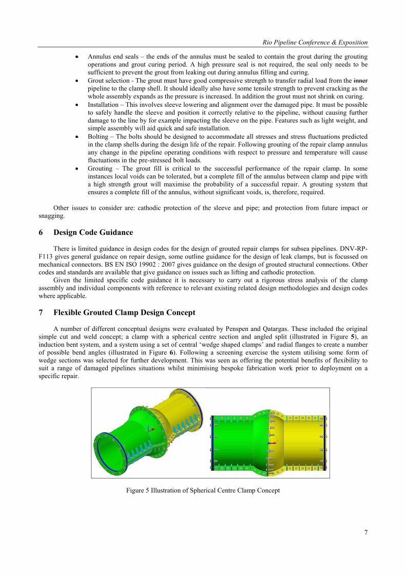
A number of different conceptual designs were evaluated by Penspen and Qatargas. These included the original
simple cut and weld concept; a clamp with a spherical centre section and angled split (illustrated in Figure 5), an induction bent system, and a system using a set of central ‘wedge shaped clamps’ and radial flanges to create a number of possible bend angles (illustrated in Figure 6). Following a screening exercise the system utilising some form of wedge sections was selected for further development. This was seen as offering the potential benefits of flexibility to suit a range of damaged pipelines situations whilst minimising bespoke fabrication work prior to deployment on a specific repair.
Figure 5 Illustration of Spherical Centre Clamp Concept
Rio Pipeline Conference & Exposition
8
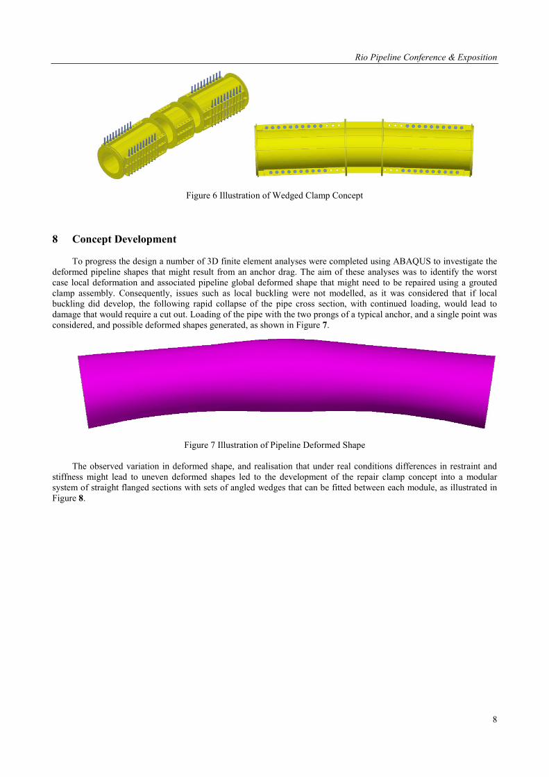
Figure 6 Illustration of Wedged Clamp Concept
8 Concept Development To progress the design a number of 3D finite element analyses were completed using ABAQUS to investigate the
deformed pipeline shapes that might result from an anchor drag. The aim of these analyses was to identify the worst case local deformation and associated pipeline global deformed shape that might need to be repaired using a grouted clamp assembly. Consequently, issues such as local buckling were not modelled, as it was considered that if local buckling did develop, the following rapid collapse of the pipe cross section, with continued loading, would lead to damage that would require a cut out. Loading of the pipe with the two prongs of a typical anchor, and a single point was considered, and possible deformed shapes generated, as shown in Figure 7.
Figure 7 Illustration of Pipeline Deformed Shape The observed variation in deformed shape, and realisation that under real conditions differences in restraint and
stiffness might lead to uneven deformed shapes led to the development of the repair clamp concept into a modular system of straight flanged sections with sets of angled wedges that can be fitted between each module, as illustrated in Figure 8.

Rio Pipeline Conference & Exposition
9
Figure 8 Illustration of Final Design Concept
This concept offers the advantage of significant flexibility due to the ability to fit wedges of different angles, and
different orientations between each clamp module. With a pre-fabricated limited range of wedge blanks available in storage it is possible to machine the required number of angled wedges to specific required angles within a matter of days to suit a specific pipeline damage situation. In addition the profiling and machining of completely new wedges can be carried out relatively quickly, pending material availability, given the sophistication of modern computerised machine shop equipment.
9 Design Process and Results
Experience and test data (Corder and Hopkins, 1993 and Harwood and Shuttleworth 1988) as well as recent
repairs (BP CATS line) indicate that a grouted clamp can in principle provide a suitable repair for pipeline anchor damage.
The outline design methodology for the repair clamps can be summarised as follows:
• Generate upper bound deflected pipeline shapes and local pipeline ovalities for the defined damage types using ABAQUS 3D FE models.
• Optimise individual clamp and assembly geometries to suit predicted pipeline global deflected shapes, local ovalities and grout annulus geometry operational and code restrictions.
• Optimise individual clamp details, including bolting requirements based on an assessment of pipeline/clamp load sharing.
• Run ABAQUS FE analyses of combined pipeline/grout/clamp models to confirm design process and highlight areas of stress concentration.
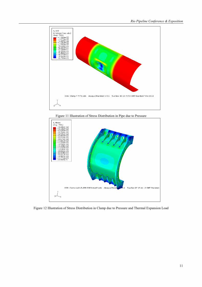
A typical combined/grout/clamp ABAQUS model is presented in Fig 9 and typical stress plots under the effect of
pipeline pressure and temperature presented in Figures 10 to 13.
The stress plots illustrate the following:
• The normal hoop stresses in the pipeline are reduced by the restraining effects of the clamp • Any local dents or similar defects are reinforced locally resulting in reductions in local stresses • In combination these effects result in significant reductions in combined pipeline stresses at the defect
location
Wedge
Clamp Module

Rio Pipeline Conference & Exposition
10
The design work highlighted the significance of the pipeline pressure and temperature at the time of repair in relation to the future pipeline operating conditions. In general terms the lower the pipeline pressure and temperature at the time the repair is carried out the more efficient the clamp will be in sharing pipeline radial effects. This benefit has to be offset against the operator’s understandable reluctance to reduce pipeline throughput any more than is considered safe and necessary.
Figure 9 Repair Clamp/Grout/Pipeline FE Model and Elements
Figure 10 Illustration of Stress Distribution in Clamp due to Pressure Load
Rio Pipeline Conference & Exposition
11
Figure 11 Illustration of Stress Distribution in Pipe due to Pressure
Figure 12 Illustration of Stress Distribution in Clamp due to Pressure and Thermal Expansion Load
Rio Pipeline Conference & Exposition
12
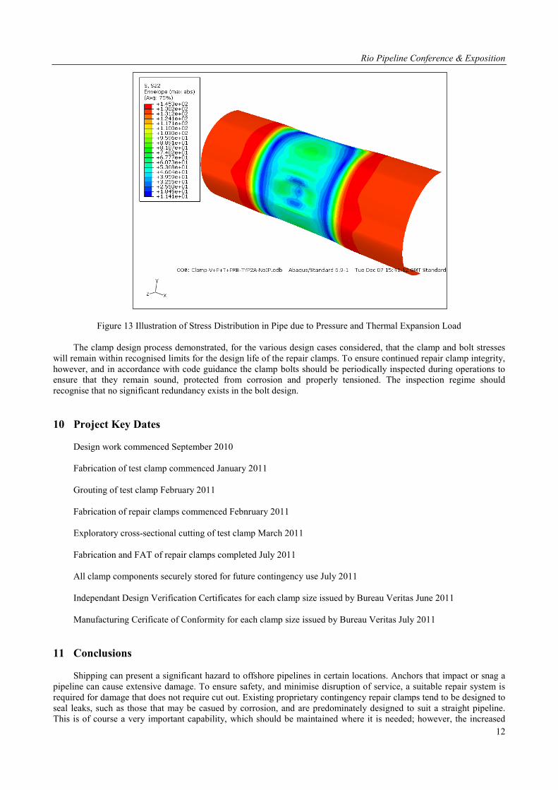
Figure 13 Illustration of Stress Distribution in Pipe due to Pressure and Thermal Expansion Load The clamp design process demonstrated, for the various design cases considered, that the clamp and bolt stresses
will remain within recognised limits for the design life of the repair clamps. To ensure continued repair clamp integrity, however, and in accordance with code guidance the clamp bolts should be periodically inspected during operations to ensure that they remain sound, protected from corrosion and properly tensioned. The inspection regime should recognise that no significant redundancy exists in the bolt design.
10 Project Key Dates Design work commenced September 2010 Fabrication of test clamp commenced January 2011 Grouting of test clamp February 2011 Fabrication of repair clamps commenced Febnruary 2011 Exploratory cross-sectional cutting of test clamp March 2011 Fabrication and FAT of repair clamps completed July 2011 All clamp components securely stored for future contingency use July 2011 Independant Design Verification Certificates for each clamp size issued by Bureau Veritas June 2011 Manufacturing Cerificate of Conformity for each clamp size issued by Bureau Veritas July 2011
11 Conclusions Shipping can present a significant hazard to offshore pipelines in certain locations. Anchors that impact or snag a
pipeline can cause extensive damage. To ensure safety, and minimise disruption of service, a suitable repair system is required for damage that does not require cut out. Existing proprietary contingency repair clamps tend to be designed to seal leaks, such as those that may be casued by corrosion, and are predominately designed to suit a straight pipeline. This is of course a very important capability, which should be maintained where it is needed; however, the increased
Rio Pipeline Conference & Exposition
13
use of internal inspection means that corrosion leaks which require emergency repair can be avoided. Accidental anchor damage cannot be totally avoided and the resulting potentially severe deformation damage to subsea pipelines has conventionally required the design and manufacture of bespoke repair clamps, since the available proprietary contingency leak repair clamps may not be suitable or may not fit. This inevitably results in a delay in the time to repair.
The flexible grouted clamp is a novel new cost effective repair method which provides a useful addition to the systems available to offshore pipeline operators for emergency repair.
The detailed design and analysis programme completed for the flexible grouted clamp has demonstrated the
following advantages for the system: 1. It will provide a permanent repair for a wide range of typical deformation and displacement anchor damage. 2. It can be mobilised within days, cutting weeks, if not months, from the repair schedule for more traditional
bespoke clamps 3. It can readily be set up to fit a wide variety of different deformation shapes. 4. No pre-installation fabrication hot work is required. 5. 1 set of clamp modules can be designed to cover two pipeline diameters, reducing inventory requirements. 6. It can be installed using the equipment found on standard diving support vessels and widely available grouting
spreads commonly used offshore.
By investing in the development of the flexible grouted clamp for their offshore pipelines, combined with the extensive other equipment put in place to facilitate a cut out repair, Qatargas have ensured that they have a world class emergency pipeline repair system that will enable them to quickly and efficiently repair the widest possible range of credible damage, thus minimising time out of service, maximising system reliability, and ensuring reliable supplies of LNG to their customers around the world.
12 Acknowledgements
The authors would like to thank Qatargas for supporting the project and allowing the publication of this paper.
They would also like to thank friends and colleagues for their support and advice, in particular Professor Phil Hopkins.
13 References ABAQUS v6.8, ABAQUS Inc 2010 BS EN ISO 19902:2007, Petroleum and Natural Gas Industries – Fixed Steel Offshore Structures. CORDER, I., HOPKINS, P., The Repair of Pipeline Defects Using Epoxy Filled Sleeve Repair, AGA 8th Symposium on
Linepipe, Houston USA, September 1993. Det Norsk Veritas, Pipeline Subsea Repairs, DNV Recommended Practice RP F113, October 2007. ESPINER, R., KAYE, D., HOPKINS, P., GOODFELLOW, G., Inspection & Assessment of Damaged Subsea
Pipelines: A Case Study, 7th Internaltional Pipeline Confernece, Calgary, Canada IPC2008-64480 October 2008. GJERTVEIT, E., Kvitebjorn Gas Pipeline Repair, UTC 2010, Bergen, Septenber 2010. HARWOOD, R.G., SHUTTLEWORTH, E.P., GROUTED AND MECHANICAL STRENGTHENING AND REPAIR OF TUBULAR STEEL OFFSHORE STRUCTURES, Health and Safety Executive Report OTH 88 283, London 1988. MAIB, Report on the investigation of Young Lady Dragging anchor 5 miles east of Teesport and snagging the CATS
gas pipeline, resulting in material damage to the pipe, 25 June 2007. Marine Accident Investigation Board Report No. 3/2008, February 2008.
JASKE C.E., HART B.O., BRUCE W.A., Pipeline Repair Manual, Pipeline Research Council International, August 2006.
PAMLER-JONES, R., TURNER, T., JOHN, R., NESPECA, G., Rapid Desision Making in Emergency Subsea Pipeline Repair, IBP 1032_11, Rio Pipeline Conference, Rio de Janiero, September 2011.