Embed Size (px)
Citation preview

UNCLASSIFIED
AD NUMBER
AD296137
NEW LIMITATION CHANGE
TOApproved for public release, distributionunlimited
FROMDistribution authorized to U.S. Gov't.agencies and their contractors; ForeignGovernment Information; SEP 1962. Otherrequests shall be referred to BritishEmbassy, 3100 Massachusetts Avenue, NW,Washington, DC 20008.
AUTHORITY
DSTL, AVIA 6/20632, 16 Apr 2009
THIS PAGE IS UNCLASSIFIED
UNCLASSIFIED
l)296 137
ARMED SERVICES TECIEICAL INFORMATION AGENCYARLINGTON HALL STATIONAR.LINGTON 12, VIRGINIA
UNCLASSIFIED

NOTICE: When government or other drawings, speci-fications or other data are used for any purpose
other than in connection with a definitely related
government procurement operation, the U. S.
Government thereby incurs no responsibility, nor any
obligation whatsoever; and the fact that the Govern-
ment may have formulated, furnished, or in any way
supplied the said drawings, specifications, or other
data is not to be regarded by implication or other-
wise as in any manner licensing the holder or any
other person or corporation, or conveying any rightsor permission to manufacture, use or sell anypatented invention that may in any way be relatedthereto.

NOTE TECH. NOTEC/: !. ENG. 335 MECH. ENG. 335
C
C-.) <r (FARNBOROUGH)
C 0 TECHNICAL NOTE No. MECH. ENG. 335
FACTORS EFFECTING THE DESIGNC"J OF A SYSTEM FOR TOWING A BODY
ON A LONG LENGTH OF WIRE
by
G. W. H. Stevens
MARCH, 1961
Amended SEPTEMBER, 1962
NO 7'
THE R:CIPIENT IS WARNED THAT INFORMATION
CONTAINED IN THIS DOCUMENT MAY BE SUBJECTTO PRIVATELY-OWNED RIGHTS.
MINISTRY OF AVIATION, LONDON, W.C.2
UNCLASSIFIED
U.D.C. No. 621.426 533.6.011 629.1.013
Technical Note No. Mech Eng 335
M-arch, 1961
Amended September, 1962
ROYAL AIPCRAFT ESTABLISHMENT
(FARNBOROUGH)
FACTORS EFFECTING TE DESIGN OF A SYSTMFI FOR
ITOWING A BODY ON A LONG LENGTH OF WIRE
by
G.W.H. Stevens
R.A.E. Ref: A2/1005/GIHS
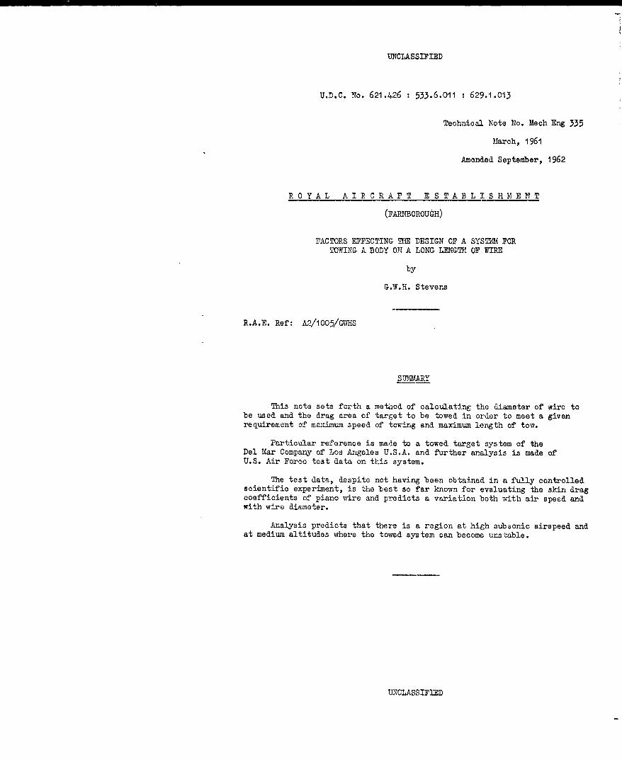
S MIARY
This note sets forth a method of calculating the diameter of wire tobe used and the drag area of target to be towed in order to meet a givenrequirement of maximum speed of towing and maximum length of tow.
Particular reference is made to a towed target system of theDel Mar Company of Los Angeles U.S.A. and further analysis is made ofU.S. Air Force test data on this system.
The test data, despite not having been obtained in a fully controlledscientific experiment, is the best so far known for evaluating the skin dragcoefficients of piano wire and predicts a variation both with air speed andwith wire diameter.
Analysis predicts that there is a region at high subsonic airspeed andat medium altitudes where the towed system can become unstable.
UNCLASSIFIED

Technical Note No. Mech Eng 335
LIST OF CONTENTS
1 INTRODUCTION 32 THE DEL WAR SYST A 33 BASIC DESIGN CRITERIA 3
3.1 The minimum drag of towed body 33.2 The skin drag of wire 43.3 Maximum working stress 4
4 DESIGN FOR A LOWo ALTITUDE - HIGH SPU,]D SYSTEM 55 THE PERFORMANCE OF THE DEL MAR SYSTRA WITH DF-4MFC TARGET 56 HIGH 3PEED - HIGH ALTITUDE INSTABILITY 6
7 LIMITS OF LENGTH OF 7IRE IHIP 78 CONCLUSIONS 7
LIST OF REFERENCES 8ADVANCE DISTRIBUTION 8
APPEN'DICES 1 AND 2 9-14TABLES 1 AND 2 15-17
ILLUSTRATIONS - Figs.1-5
DETACHABLE ABSTRACT CARDS
LIST OF APBNDICES
Appendix
1 - Method of determining. tha-diameter of wire for along tow length 9
2 - Data on drag of wires 13
LIST OF TABLES
Tabl e
1 - Abstract of data from U.S.A. Report APGC-TR-59-39 15
2 - Re-evaluation of Del Mar performance estimate usingrevised wire drag data 17
LIST OF ILLUSTRATIONS
Fig.Analysis of contributions to tension 1
Relation between maximum tow length and airspeed 2
Unstable flight reCions 3Measured mean inclinations of wire 4
Mean skin drag coefficient for smooth wire 5
-2-

Technical Note No. Lech Eng 335
I INTRODUCTION
The U.K. Serviceshave become interested in a U.S. systemof towing a target on a long length of piano wire, the Del Mar system. TheArmy have stated that they would like to be able to tow a target on 15,000 ftof wire at speeds of 400 knots and at heights between 500 ft and 7000 ft.The Navy have stated that they would like to tow as long a length as possibleat operating altitudes between 30,000 and 40,000 ft and at speeds not muchless than the normal operating speeds at these altitudes.
The purpose of this note is to review the design requirements of asystem for towing a body at some distance behind an aircraft and to statecertain physical limitations.
2 THIE DE L 1WEA SYSTEM
The Del Mar system is fully described1 in brochures of the firm but itis essentially a low-drag bomb-like body, which rotates axially in flightand which is towed on a long length of piano wire. This wire can be winchedin and out and the target can be released from and retracted into a carrieron the wing. More than one design of target is available and over 30,000 ftof wire can be carried on the drum. The diameters of wire used have been0.045 in. and 0.051 in.
CTest information shows that the system can be operated on lengths of
tow up to 30,000 ft, at speeds up to Mach 0.75 and at heights up to 40,000 ft.
3 BASIC DESIGN CRIT:1RIA
There appear to be three basic design criteria which can define asystem.
1 The minimum drag of towed body.
2 The worst operating conditions for skin friction.
3 The factor of reserve strength on the wire.
Uhat is requirel is a logical means of proceeding from them to a design.3.1 The minimum dra.g of towed body
The minimum drag of the towed body can be determined on the assumptionthat the wire near the body can be prevented from whipping. The tension inthe wire, arising from the combined weight and drag of the body, must besufficient that transverse waves in the wiro will travel faster than theairflow4 . This is a condition which can be used to determine the diameterof wire to satisfy the requirement of a maximum towing length and maximumspeod, subject to the maximum stress limitation in the wire being stated.This design relationship is worked out in Appendix 1.
It is seen that for a given speed the length of tow is proportionalto the diameter of the wire and it also depends directly on the skin dragcoefficient of the wire. It is also seen that the maximum towing speed isrelated to the tenacity, e.g. strength/weight ratio, of the wire and, forhigh speed towing,a high quality wire is required. There is a critical speedabove which it would be impracticable to tow a body stably even on a shortlength of tow. These critical speeds are calculated to occur in the lowsupersonic range by the method of Aopendix 1, assuming that if this can beapplied at such speeds, the high density of steel wire is an advantage and itwould not be possible to obtain as good a performance with a low densityplastic filament such as nylon or polypropylene.
-3-

Technical Tote No. Mech Eng 335
3.2 The skin drag of wire
It appears that the best data on the skin drag of piano wire can bededuced from actual air tests on a Del Yar system 2. Early wind tunnelexperiments on the drag of wires 7 do not give such reliable results on skindrag although the estimates of normal profile drag appear to agree closelywith the more recent results.
The drag measurements on the Del Mar system are analysed in Appendix 2.The values of skin drag coefficients show a variation with speed and wirediameter ranging from about 0.018 to 0.012 over the speed range of 175 to300 knots. The value quoted by Hoerne, and used by the Del Mar Company intheir design brochure, lies within the observed range. The trend of variationwith speed and diameter agrees with that predicted by the method of Glauertand Lighthill 9 despite the fact that the method does not give the correct
absolute magnitude.
It is presumed that the wire used in the tests at Eglin Air Force Base,U.S.A. was substantially new, smooth and oiled. It is of some concern whetherthe skin friction increases as the surface deteriorates. The possibility ofdrums of wire used at sea on aircraft carriers being effected by sea spraymust not be overlooked and some factor in design to meet this contingency maybe required.
3.3 Maximum working stress
The Del Mar Company claim, the report of Eglin Air Force Base, concurs, .thatit is possible to work to 85A of the ultimate strength of the wire. It isdifficult to believe that the straining due to winding on a limited diameterof drum, disturbances due to uneven flight and non-uniform airflow along thelength of the wire and effects of winch operation do not make it necessary tohave a greater factor of safety. The standard deviation of the tensionsmeasured in different flights for the same operating conditions is 7J% of themean. Most of this observed variation arises from the second cause mentionedabove and any high frequency fluctuation will be averaged out in the testreadings. With this observed standard deviation of tension it is clearly notsafe to work to such a low factor for it would give a one in twenty chance offailure.
The major source of weakness in the system arises from the fact that thewire is wound onto a drum of limited diameter. A wire of diameter 0.045 in.wound on a drum of 9 in. diameter will have a difference of strain between theaxis and the skin of 0.005. This is of the order of the yield strain of well-drawn piano wire. Since, in this equipment$ there are no tension blocks andsurge drums, as in a balloon winch, the tension is transmitted directly to thewinch. Thus the elastic limit of the wire is likely to be exceeded on thedrum and the wire to be given a permanent set. When the wire is unwound againits natural coil will be straightened and the wire will be unevenly stressedacross its section. It will not necessarily be rewound with the coils in thesame lay.
To operate on a winch as described above it is necessary to use asufficiently soft wire so that it yields to the winching strains. However, theprocess of winching in and out at a high stress will work harder the wire andit is likely to attain eventually a brittle condition.
The yield strain for many qualities of piano wire is in the region of0.007 to 0.009 and the ultimate strain is about 0.012 and 0.015. It wouldappear desirable to limit the local strain to 0.010 which would require themean working strain not to exceed 0.005 if, in fact, a local variation of±0.005 occurs on the winch. This would limit the stress to about 60-70 tonsper sq in. in the wire.
-4-
Technical Note No. Hech Eng 335
2In the recorded test data the highest tension recorded, 354 lb. is
72% of the quoted ultimate, 490 lb, and represents a mean stress of nearly100 tons per sq in. so that the wire will be suffering permanent strain.
In addition to the effects discussed above there will be tension surgesof which little is kno-n of their significance. It is likely that any highfrequency drag variation due to eddy shedding by the towed body may be dampeddown by the time the effects arrive at the towing point because transientmotions are heavily damped at low speeds.
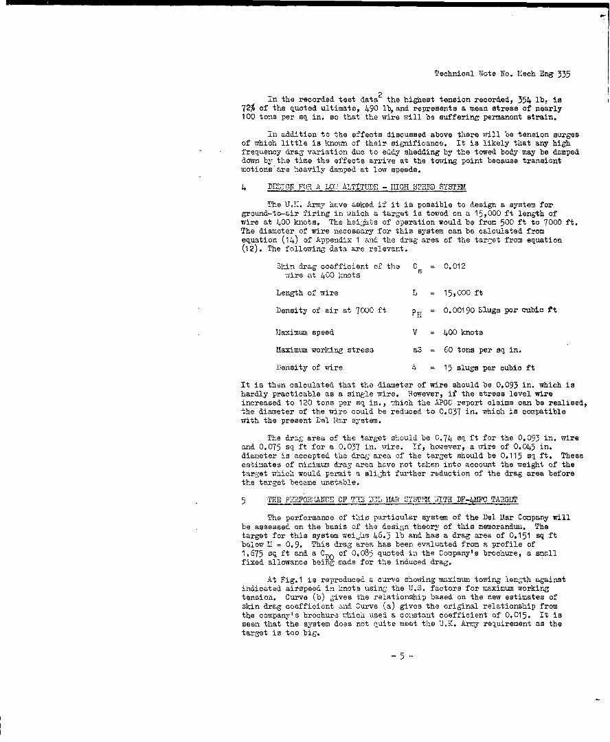
4 DE0i1N FOR A L07 ALTITUDE - HIGH SPEED SYSTIN
The U.K. Army have asked if it is possible to design a system forground-to-air firing in which a target is towed on a 15,000 ft length ofwire at 400 knots. The heights of operation would be from 500 ft to 7000 ft.The diameter of wire necessary for this system can be calculated fromequation (14) of Appendix I and the drag area of the tarcet from equation(02). The following data are relevant.
Skin drag coefficient of the Cs = 0.012wire at 400 knots
Length of wire L = 15,000 ft
Density of air at 7000 ft PH = 0.00190 Slugs par cubic ft
Maximum speed V = 400 knots
Maximum working stress aS = 60 tons per sq in.
Density of wire 6 = 15 slugs per cubic ft
It is then calculated that the diameter of wire should be 0.093 in. which ishardly practicable as a single wire. However, if the stress level wire
increased to 120 tons per sq in., ;hich the APGC report claims can be realised,the diameter of the wire could be reduced to 0.037 in. which is compatiblewith the present Del RIar system.
The draEg area of the target should be 0.74 sq ft for the 0.093 in. wireand 0.075 sq ft for a 0,037 in. wire. If, however, a wire of 0.045 in.diameter is accepted the drag area of the target should be 0.115 sq ft. Theseestimates of minimum drag area have not taken into account the weight of thetarget which would permit a slight further reduction of the drag area beforethe target became unstable.
5 THE PjRFO1ZRAIICE OF TT3E DY2L 11AR SYSTTX JITH DF-412C TARGL'
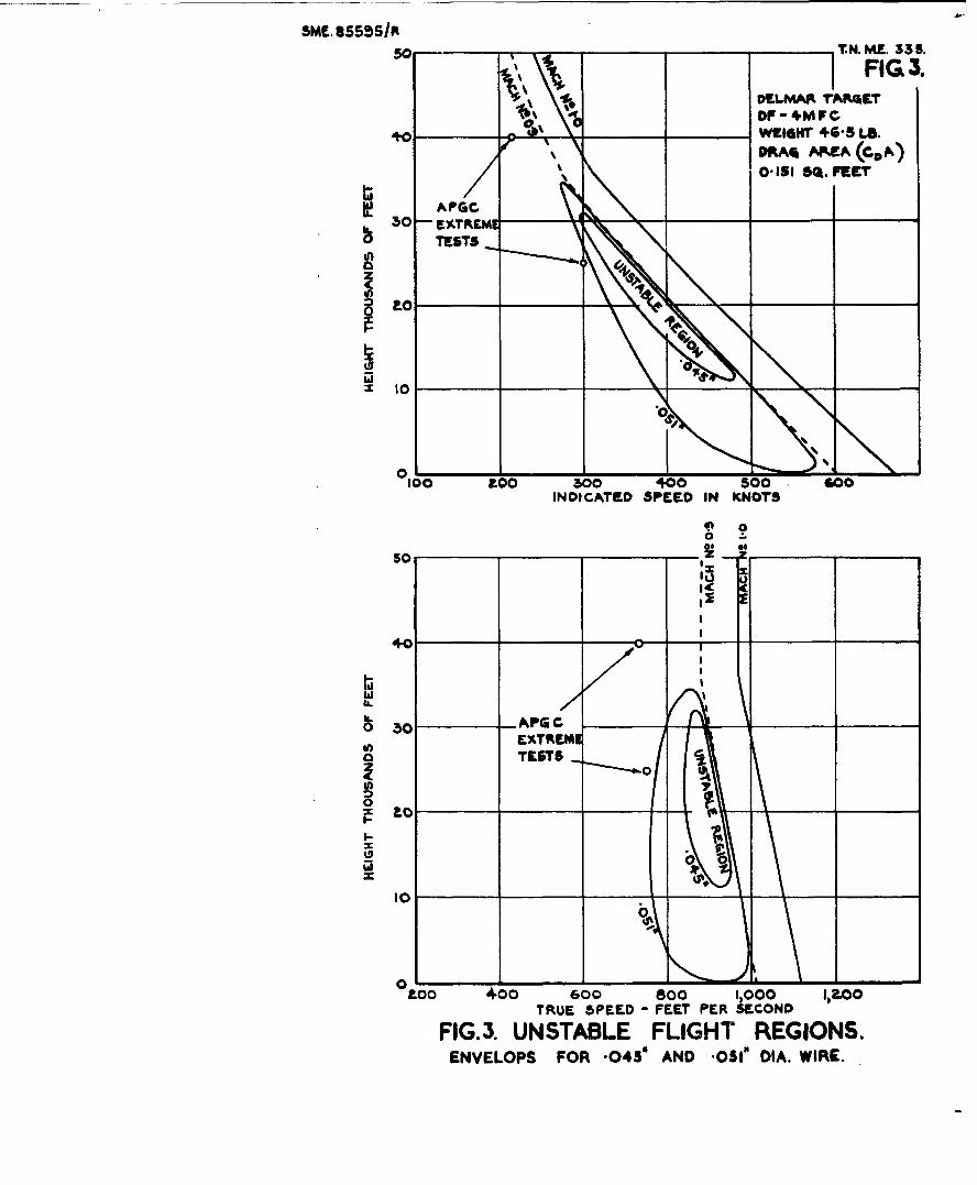
The performance of this particular system of the Del Mar Company willbe assessed on the basis of the design theory of this memorandum. Thetarget for this system Weiahs 46.3 lb and has a drag area of 0.151 sq ftbelow M = 0.9. This drag area has been evaluated from a profile of1.675 sq ft and a C of 0.085 quoted in the Company's brochure, a smallfixed allowance being made for the induced drag.
At Fig.1 is reproduced a curve showing maximum towing length againstindicated airspeed in knots using the U.S. factors for maximum workingtension. Curve (b) gives the relationship based on the new estimates ofskin drag coefficient and Curve (a) gives the original relationship fromthe company's brochure which used a constant coefficient of 0.015. It isseen that the system does not Quite meet the U.K. Army requirement as thetarget is too big.
-5

Technical Note No. Mech Eng 335
It is useful to see how target weight and drag, wire weight, and wiredrag contribute to the total tension and this is illustrated in Fig.2. Wiredrag accounts for about 80% of the total tension and wire weight is negligibleat the order of airspeed at which it is required to fly. The basis forcalculated these curves is summarised in Table 2.
6 HIGH SPEED - HIGH ALTITUDE INSTABILITY
Although the drag of the DF-4MFC target is sufficient to ensurestability of the end at low altitudes it is shown in Appendix I that, if thesystem is flown at certain heights and speeds, the end of the wire and targetcan become unstable. This is a phenomenon which can occur with parachutestrops3 .
Stability is assured when
K a sec 3 a > mK0
where m is the mass per unit length of the wire
K is the velocity coefficient of drag at normal pressure
a is the density ratio pH/Oo
a is the inclination of the wire from the horizontal at the target.
This inequality can be upset by flying higher and so reducing T or by flyingfaster and so reducing a. However, as sonic speeds are approached K willo
increase and restore the inequality. According to the firm,K 0 will begin to
rise sharply at M = 0.9.
The value of K° is 1.81 x 10- 4 and the ratio m/K is worked out for the
following diameter, d, of wire
d min. slugs per ft
/K
0.040 1.295 x 10 "4 0.715
0.045 1.685 0.93
0.051 2.12 1.175
The finite weight of target is clearly important in limiting theinstability to high subsonic speeds and the envelop is plotted in Fig.3 forheight against true speed for the cases of 0.045 in. and 0.051 in. wires.The high Mach number boundary of the envelop is only approximate. It is takenarbitrarily at M = 0.9 as no exact information is available on the drag rise.
The plots show that the extreme tests of APGC report are still in thestable region of flight but approach the calculated envelop very closely forthe 0.051 in. wire. They illustrate that increasing the strength of the wiremay be no answer to improving the performance without reviewing the system asa whole.
-6-.
Technical Note No. Mech Eng 335
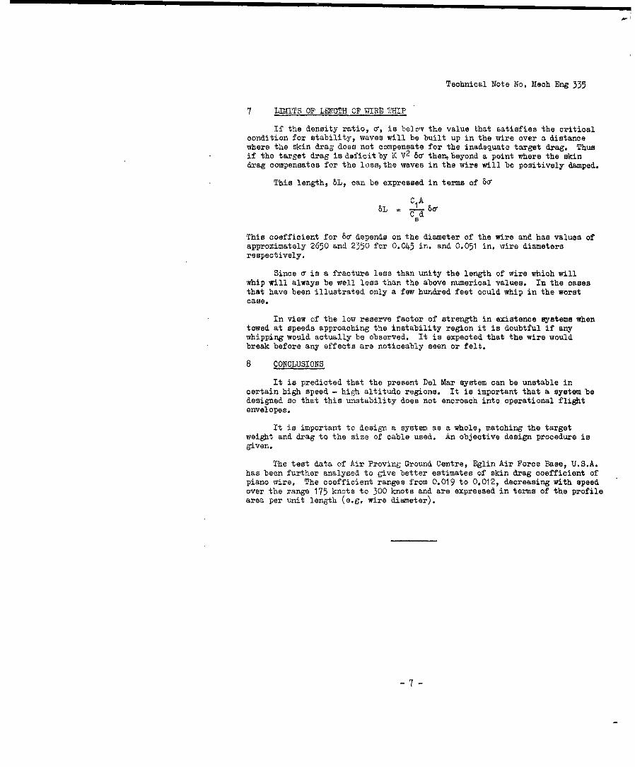
7 LITS OF LENGTH OF WIRE TraIP
If the density ratio, v, is below the value that Batisfies the criticalcondition for stability, waves will be built up in the wire over a distancewhere the skin drag does not compensate for the inadequate target drag. Thusif the target drag is deficit by K V2 8c the beyond a point where the skindrag compensates for the loss, the waves in the wire will be positively damped.
This length, 8L, can be expressed in terms of 8a
CIA6L - 60-
C dS
This coefficient for 8o depends on the diameter of the wire and has values ofapproximately 2650 and 2350 for 0.045 in. and 0.051 in. wire diametersrespectively.
Since a is a fracture less than unity the length of wire which willwhip will always be well less than the above numerical values. In the casesthat have been illustrated only a few hundred feet could whip in the worstcase.
In view of the low reserve factor of strength in existence systems whentowed at speeds approaching the instability region it is doubtful if anywhipping would actually be observed. It is expected that the wire wouldbreak before any effects are noticeably seen or felt.
8 CONCLUSIONS
It is predicted that the present Del Mar system can be unstable incertain high speed - hi(ch altitude regions. It is important that a system bedesigned so that this unstability does not encroach into operational flightenvelopes.
It is important to design a system as a whole, matching the targetweight and drag to the size of cable used. An objective design procedure isgiven.
The test data of Air Proving Ground Centre, Eglin Air Force Base, U.S.A.has been further analysed to give better estimates of skin drag coefficient ofpiano wire. The coefficient ranges from 0.019 to 0.012, decreasing with speedover the range 175 knots to 300 knots and are expressed in terms of the profilearea per unit length (e.g. wire diameter).
-7-

Technical Note No. Mech Eng 335
LIST OF REFERETCES
No. Author Title, etc.
1 Del Mar Company The aerodynamic characteristics of the Del MarFlare Target Model DF-4MFC.Report No. 685
2 Bartlett, W.L. Drag and compatibility test of the TDU-4/B targetwith the B-57D external lightweight tow system.Air Proving Ground Centre, Eglin Air Force Base,Florida, U.S.A. August, 1959.
3 Stevens, G.71.H. The minimum parachute size and maximum towing speedin relation to strop characteristics.R.A.E. Tech Note No. ME 311. January, 1960.
4 Phillips, W.H. A theoretical analysis of the oscillations of a towedcable. N.A.C.A.Report No. 1796.
5 Glauert, H. Hoavy flexible cable for towing a heavy body belowan aeroplane.A.R.C. R & Ir No. 1592 February, 1934
6 Carter, W.J. The shape of a trailing cable. R.R.L.A.F.Tech Memo No. 33 Defence Research LaboratoryUniversity of Texas U.S.A. March, 1957.
7 Relf, E.F., Tests on smooth and stranded wires inclined to thePowell, C.H. wind direction
A.R.C. R & M No. 307.
8 Hoerne, J.F. Aerodynamic Drag.
9 Glauert, Proceedings of a symposium on boundary layer effectsLighthill, M.J. in aerodynamics (N.P.L. 1955).
10 McLeod, A.R. On the action of wind on flexible cables withapplication to cables towed below aeroplanes.A.R.C. R & M No. 554.
ATTACHED: -
Appendix 1 & 2Tables 1 & 2Fig. No. 1-5 WAE 85593/R-SKE 85596/RDetachable Abstract Cards
ADVANCE DISTRIBUTION:
DGAGS Head of Radio DeptD/RAF/A Head of Aero DeptRAF/A5(Action) Aero Dept (Mr. Spence)
RAF A5(Mr Cracknell) Head of Structures DeptADICW Eng A & A.E.E. (A & H Div)TIL 1120 Library RAEDirector RAE RAE Bedford LibraryDD RAE(AS Pats /AE
- 8-
Technizal Note No. Mech Eng 335
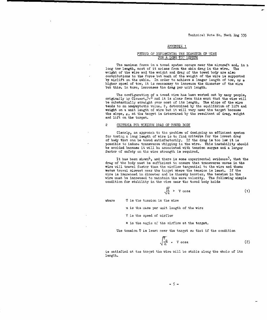
APPEYNDIX 1
ETHOD OF DETERNINING THE DIMAETER OF \3IREFOR A LONG TO' LMTGTH
The maximum force in a towed system occurs near the aircraft and, in along tow length, most of it arises from the skin drag in the wire. Thewoight of the wire and the weight and drag of the towed body are alsocontributions to the force but much of the weight of the wire is supportedby airlift on the cable. In order to achieve a longer length of tow, or ahigher speed of tow, it is necessary to increase the diameter of the wirebut this, in turn, increases the drag per unit length.
The configuration of a towed wire has been worked out by many people,originally by Glauert,5, 6 and it is clear from this work that the wire willbe substantially straight over most of its length. The slope of the wiretends to an assymptotic value, 8, determined by the equilibrium of lift andweight on a unit length of wire but it will vary near the target becausethe slope, a, at the target is determined by the resultant of drag, weight
and lift on the target.
2 CRITERIA FOR MINIMMI DRAG OF TOWDFO BODY
Clearly, an approach to the problem of designing an efficient system
for towing a long length of wire is to find criteria for the lowest. dragof body that can be towed satisfactorily. If the drag is too low it ispossible to induce transverse whipping in the wire. This instability shouldbe avoided because it will be associated with tension surges and a largerfactor of safety on the wire strength is required.
It has been shown4 , and there is some experimental evidence3 , that thedrag of the body must be sufficient to ensure that transverse waves in thewire will travel faster than the airflow tangential to the wire and thesewaves travel slowest near the target where the tension is least. If thewire is increased in diameter, and is thereby heavier, the tension in thewire must be increased to maintain the wave velocity. The following simplecondition for stability in the wire near the towed body holds
> V cosa (i)
where T is the tension in the wire
m is the mass per unit length of the wire
V is the speed of airflow
a is the angle of the airflow at the target.
The tension T is least near the target so that if the condition
V cosa (2)
is satisfied at the target the wire will be stable along the whole of itslength.
-9-

Technical Note No. Mech E-ng 335Appendix 1
The tension, T0, is the resultant of weiGht, V, and the drag, D, ofthe target so it is possible to write
To + Dm 2 Cos 2 (3)
for the conditions of stability. Moreover, tan a = so that
(I2 + D2)3/2 > mV2 D2 (4)
When a drag force p-oportional to the square of the velocity can be azsed&it is possible to write D = KV2 whereupon
sec 3 0 > E (5)K
The coefficient K will depend on air density so that it is possibleto write
sec 3 a M(6)
where K is the coefficient at sea level and r is the density ratio.
When the speed of towing is high sec a will not be ve-j different fromunity. Thus it is seen that if Ko is equal to mo. at the height for which
the system is to be operated then stability is always assured. It is alsoseen that when the wei3ht of the wire is increased the drag coefficient mustbe increased proportionally. If Ko is less than the value given by m/0 then
the system may still be stable at some lower speed because of the angle athat the wire is inclined to the airflow at the towed body.
3 TMTSION IN MHE CABLE
In a very long length of towed wire, apart from the curved portion nearthe target, the inclination with respect to the airflow, assuming it to behomogeneous over the whole length, is substantially constant. It can be shownthat the angle of inclination, of the wire to the airflow, approaches anassymptotic value, e, and, for small angles,
e = ×F 1' (7)
The quantity, k, is the normal drag area multiplied by half the air density.It is seen that the angle, e, is inversely proportional to the airspeed, V.
The rate of change of tension with length along the wire at this slope, 6,is
dT - k V2 Cos2 a gm sc (8)
&s
but as 6 is a small angle it is adequate to many cases to write
dT k V2 (9)ds s
-10-

Technical Note No. Mech Eng 335Appendix I
where ks is the velocity coefficient for skin drag. Thus in the high speed
case the tension T at the aircraft approximates toa
Ta = ks V2L + To (10)
where L is the length of the wire. The curvature of the cable near the towedbody and the sag of the cable will produce a small increment of tension.
The tension, Ta, can be expressed also in the following form
T a ' :H (%A + Csd L) V (11)
where PH is the air density appropriate to the design height
d is the diameter of the wire
L is the length of the wire
V is the airspeed in ft per second
C is the skin drag coefficient as defined in R & IA 307 2kIPHd
CDA is drag area of towed body
This is a convenient form for applying the criteria of section 2.
4 REIATIONS FOR CRITICAL T INAL CONDITIONS
Co-relating the forms of expression in section 2 and 3 the conditionK = m when a tends to zero can be replaced by
A = d2 , (12)
where A is the density of the wire.
The maximum tension will also be limited by the diameter of the wireand the tension can be expressed in terms of the ultimate strength, S, ofthe wire by
T = ax d 2 S
a 4
where a is a factor for safe working below the ultimate strength.
A substitution can now be made in equation (11) giving
a d2 S = ( - d2 V2-I
a C S -Z dsd L) V2 (13)
which can be simplified to
d = 2PH CsL (14)
which gives the minimum wire diameter.- 11 -

Technical Note No. Mech Eng 335Appendix 1
5 WIRE DIAElTER TO MET A REQUIRRTM
In equation (14) there has been obtained an explicit equation for theminimum diameter of wire to satisfy a specified requirement of maximum speedand length of tow. It is seen from this equation that the efficiency ofmeeting a particular requirement is dependent upon a high tenacity, definedas S/A, and it is important that aS/A V2 is substantially larger than unity.If this quantity is not very different from unity then the diameter of wirefor a modest length of tow becomes prohibitive. This is a condition that isapproached if the design speed is high. This is a physical limitation notedwith respect to the design of strops for parachute equipment at high speeds 3 .
It is also noted from equation (14) that d/L is a function of thedensities of the air and of the wire material. It is also important to notethat the ratio S/A represents the tenacity of the material and this quantityhas about the same magnitude for both steel and nylon wires. For materialsof the same tenacity it is possible to say that the ratio d/L is proportionalto the ratio of the densities PH/A. Thus if a low density material such as
nylon or polypropylene wire is used, the diameter of the wire must be sevento eight times the diameter of piano wire to meet the same requirement ofmaximum length of tow. Since tensions will be roughly proportional to thediameter of the wire, the system with the higher densitr wire is clearly themore efficient.
. CORRECTION TO TENSION FOR WEIGHT OF 7IRE
The tension in the wire will partly arise from its weight and the ruleof Glauert5 can be used which states that the increase in tension due toweight is given by the vertical depression of the target below the wire.This allows also for the curved portion of the towing wire near to the target.
Having determined the wire diameter on the 'asia of the first orderequation (14) one should re-evaluate the wire tension allowing for thecomponent of weight of the wire and for the exact terminal tension. Fromequation (7) an expression for the weight component can be introduced as asecond order term in equation (10) to give
V2, + fm_7 LT+. T +k Vk V X mg (15)
a o s k t
The above equation can be expressed as
T =To + k VL ( ( 2 .~ (16)
in which it is seen that contributions from the weight of the wire can beexpressed as a correction factor to the skin drag coefficient.
The coefficient of L is of the form V2 + (A/V) which has a minimum valueat a certain value of the airspeed, V. This speed, however, is found to bebelow practical flying speeds so that the weight of the wire never becomes aterm more prominent than the skin drag.
- 12-
Technical Note No. Mech Eng 335
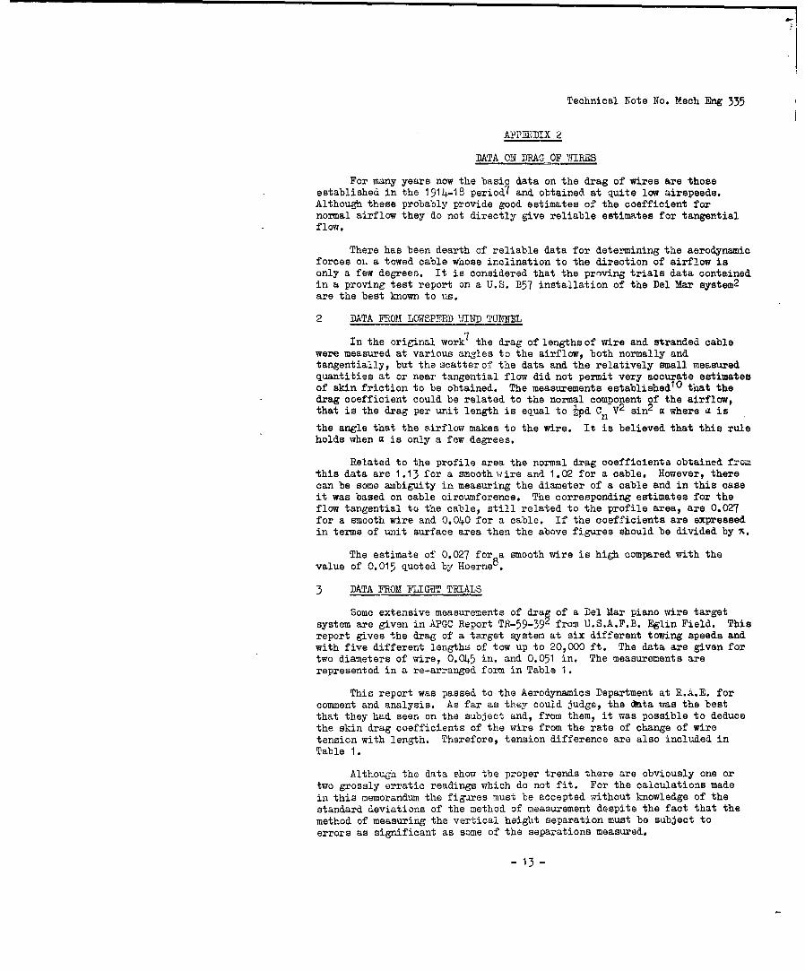
APPMIDIX 2
DATA ON DRAG OF WIRES
For many years now the basic data on the drag of wires are thoseestablished in the 1914-18 period( and obtained at quite low airspeeds.Although these probably provide good estimates of the coefficient fornormal airflow they do not directly give reliable estimates for tangentialflow.
There has been dearth of reliable data for determining the aerodynamicforces oi. a towed cable whose inclination to the direction of airflow isonly a few degrees. It is considered that the proving trials data containedin a proving test report on a U.S. B57 installation of the Del Mar system2
are the best known to us.
2 DATA FROM LOWSPED 'WIND IUKEL
In the original work 7 the drag of lengths of wire and stranded cablewere measured at various angles to the airflow, both normally andtangentially, but the scatter of the data and the relatively small measuredquantities at or near tangential flow did not permit very accurate estimatesof skin friction to be obtained. The measurements established1 O that thedrag coefficient could be related to the normal component of the airflow,that is the drag per unit length is equal to 'pd Cn V
2 sin2 a where a is
the angle that the airflow makes to the wire. It is believed that this ruleholds when a is only a few degrees.
Related to the profile area the normal drag coefficients obtained fromthis data are 1.13 for a smooth wire and 1.02 for a cable. However, therecan be some ambiguity in measuring the diameter of a cable and in this caseit was based on cable circumference. The corresponding estimates for theflow tangential to the cable, still related to the profile area, are 0.027for a smooth wire and 0.040 for a cable. If the coefficients are expressedin terms of unit surface area then the above figures should be divided by x.
The estimate of 0.027 for a smooth wire is high compared with thevalue of 0.015 quoted by Hoerne8 .
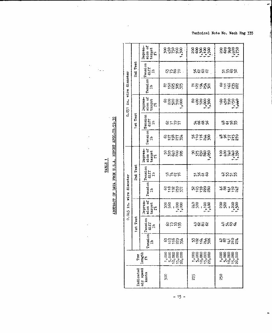
3 DATA FROM4 FLIGHT TRIALS
Some extensive measurements of drag of a Del Mar piano wire targetsystem are given in APGC Report TR-59-39 from U.S.A.F.B. Eglin Field. Thisreport gives the drag of a target system at six different towing speeds andwith five different lengths of tow up to 20,000 ft. The data are given fortwo diameters of wire, 0.045 in. and 0.051 in. The measurements arerepresentod in a re-arranged form in Table 1.
This report was passed to the Aerodynamics Department at R.A.E. forcomment and analysis. As far as they could judge, the data was the bestthat they had seen on the subject and, from them, it was possible to deducethe skin drag coefficients of the wire from the rate of change of wiretension with length. Therefore, tension difference are also included inTable 1.
Although the data show the proper trends there are obviously one ortwo grossly erratic readings which do not fit. For the calculations madein this memorandum the figures must be accepted without knowledge of thestandard deviations of the method of measurement despite the fact that themethod of measuring the vertical height separation must be subject toerrors as significant as some of the separations measured.
- 13-

Technical Note No. Mech Eng 335Appendix 2
By comparing the tensions measured at the same conditions on differentflights an estimate of standard deviation of tension can be obtained. Thishas been done for lengths of tow 10,000 ft and greater and a figure of ±7j%is obtained. Within this observation it is rather surprisiig that the testreport concludes that it is safe to work to 85% of the ultimate breakingstrength of the wire.
4 THE MEAN INCLINATION OF THE VIRE
Although the target may cause the wire to be curved downwards near thetarget the ratio of the target/aircraft height separation to the length ofwire will give a good estimate of the slope of the wire. In Fig.4, there aredrawn the two calculated curves using the normal drag coefficient of 1.13.Estimates of inclination from the figures of Table 1 and are given for the0.045 in. wire for three airspeeds. These estimates scatter about thecalculated curves to give satisfactory agreement within the limitations of themethod of test. The calculated inclination of the cable will be used tocorrect the tension differences of Table 1 using equation (16) of Appendix 1.
5 THE IEAN SKIN DRAG COEFFICIENT
The mean skin drag coefficients for the different diameters of wire andfor the various speeds have been worked out and plotted in Fig.5. Some varia-tion of coefficient with both speed and wire diameter is indicated, decreasingwith increasing speed and increasing wire diameter. The value quoted byHoerneU is confirmed to occur at speeds about 200 knots or slightly higher.It is fortunate that the trend of variation is such as to give some relief aswire diameter and speeds are increased in attempting to meet a given require-ment.
With regard to the trend of variation of skin drag with speed, themethod of Glauert and Lighthill has been used to estimate the drag of verylong lengths of wire. The method confirms the trends in relative valuesboth with respect to speed and to change in wire diameter but, unfortunately,it gives numerical values too low by a factor of forty.
The simple design theory of Appendix 1 assumes a skin drag coefficientindependent of speed and wire diameter and a drag proportional to the squareof the speed. It still appears possible to use this simple theory provideda skin drag coefficient appropriate to the maximum design speed is used. Inthe case of subsonic speeds greater than the 300 knots of the present dataany further reduction in the coefficient will be slight and the value of300 knots could be used.
- 14-
Technical Note No. Mech Eng 335
(00 0
024) 0
00
;9 0 1 000 QrI 0300 00000U1C ~ KO
P, F- CH-. ,-
0- 0 00 0 0
0C3~0N- 4\
cO-
Q 0'
t,- E-I _ _ _ _ _ _ _ _ _ _ _\_ N_ _
E-SC0
a ,0 '-ON \r- U-N-~ -t CT\ L".%, -
r-4N
4-.
0 UO4 000zt0 000 U\, 0 000U
41) 0
4E4 - -
-1 0OO C\1CY - C N y\ 0 0 0 .N~
-)
P.O0 4 44 a*
P4) C* 4)
a) 0E-f -, *4-4 0' LP O'N c' 0O\ 0-t-Y
to) 4 4 a \ - 4 t\0C\0
0Srj K" P-'ND (7\ 4 -t4 ' t- -.- 0\4, LO\J ON JU.N Lf'I\ -0 0 CC)c 4 t-
E-4
8088 0000§ HH0~~ 8 80000 008 Caa
EP -(I - -N i . - N .
-p) Lf0 0 ( r\0U- N0L*
P N N
hiCd
-15-

Technical No-te No. Hoch Eng 335
0 80000 Q8 8R80Id, CD-PC
4-'
(0 0.
0 D
044QCm 0 LI0- a) C\----0'.0
., 090 0r o0 - - \c
0 3 880 00000 80000
- 0f4 CdL ,\UNO -o \ fD - N
02 C ;
01 0E-1 -84,-
44A 0 rlN.0 0 0 10 0 AN C4- 0 #4 r4 -t LN n tLIN cfW - _ r-
(D 0
0-#4 r"CON -4CdO Cl 0III\_too
4,0 K-I0 a\ -, 0 0,00 -t E--P.4- -CV N ,- - -
t P 0 CtclN ~Lo0(V.O ----P0 V . D. aD at a' aC a2 Ya5 -t a1 ,
0 ~t. 4r4 02,-,- ,
CD 0
CA E- -H f+4--
4 ~ ~ ~ ~ ~ ~ W N t___ _______
V. rP N - r. , -0 r.
.90 0 O d ~\ 0 j -03 co a% ,- O oO
0I 0 884 02 80 00 - -80o \___O _ __N__0 _
o 44
0) 0E-4 -H4.4-4 U 0 ~ \DE- C\J0 0 0 -,-
0-t E ~ I C NO Ne E4- 0s r- N N0 NP 'IPC r - - Ns-
-4
0 ~ ~ ~ 8-I~t\ 0 1)0L0 .- L,0L-0
000§ 88
N N N
HId
-16-

Technical Note No. Mech Eng 335
TABLE 2
RE-EVALUATION OF DEL MAR PERFM0TANCE ESTIMATEUSING R:VISED WIRE DRAG DATA
Target DF-4FC
Weight 46.5 lb
Drag area 0.151 sq ft
Wire Music wire 0.045 in. diameter
Weight 5.4 x 10⁻³ lb per ft
Towing Skin Target' LTo Ta-TofF T,
speed drag drag I F I Tb thousandsknots coeff. lb lb ft
160 0.0195 12.8 48.2 367.8 1.11 331 53.3
180 0.0185 16.2 49.2 366.8 1.08 342 45.6
240 0.0145 28.8 54.5 361.5 1.04 348 34.2
300 0.0130 45.0 64.7 351.3 1.024 343 25.6
360 0.0125 64.8 80.0 330 1.0171 331 16.4
420 0.0120 88.0 99.3 316.7 1 1.O1 1 313.5 11.8
T = wire tension at targeto
T - maximum wire tension at aircrafta
= 416 lb
F = factor total tension/skin drag to correct forcomponent of wire weight
T = tension due to skin drag of wire5
L = maximum tow length
-17-

SME.855'93/tT.N. M.E. 335.
luwi
0
0~~ 0
to In ? ini
mosNai. 2.LwwUnf 00o iLv WdIPA Jo HII4AT v~4flW O~W
IL.

TN. ME. 335.FIG.2.
6000101 I~
1000OE
-0
z
00
g,1 NOISN31
SME. 8S555/it50 -____ ______ T. ME 535
F'G0
~~~aU)~V~m 30EKRE P 15 5.ET
too~015 zoo so 40 00 60
TESTTDSPEDINKNT
0O 0
In~
I
00
41q) 0~R
so o
10
,0O= 480 600 800 1,000 41200TRUE SPEED -FEET PER SECOND
FIG.3 UNSTABLE FLIGHT REGIONS.ENVELOPS FOR *045 AND -051" DIA. WIRE.

T N. .9. 335.
FIG 4&5
* MEASURINt' ONS0 4gSm Wlke
zoo 1113 ao S7 3m0
INDIC'ATCD AIRSPKD KNOMh
FIG.4. MEASURED MEAN INCLINATIONS OF WIRE.COMPARISON WITH CALCULATED CURVES.
-. ©
oz
IL
.[005
175 zoo aZs 5o s75 300INDICATED AIRSPE.D (AT Z5,0OO')
KNOTS
FIG.5. MEAN SKIN DRAG COEFFICIENT FORSMOOTH WIRE.

DETACHABLE ABSTRACT CARDS
These abstract cards are Inserted In Reports and Technical Notes for the convenienceof Librarians and others who need to maintain an Information Index.
0
F4w - R- 01Sa.- 0 (a
0. en .2 e 0 .0ww 0 0~ -0-00
r_0 00 0
.009 0 t0- IN It . ga H 1 §o a0.0- C >
i9 00 S 0% r
a~ w02-CooJ4-. .o 4 0o a 0o02 Oon* S-i - 00200 0242 ao~ Vw 0 2 a.2ol !!O. 0. .04.0G
-o 0 %00 onU. 04 w0oL 0ow wO 0'0 0o onoan'4C WN 00. OwO 04 0. a 00.0 -0
~~040 . 0 - w g -e
,a 0 n 0 cc 0 .~ 2 -O . ~S0a 'a 4- w 4 0n0 0 0 n
0. , 0 4.- 44 Won
000V. 0 . 00e ID.t Z_ C 4n 1W OZ on wo 0
r.0
01 0 w 0w W: 0 4E. C . .3 540 -4 0
0 .40 S *..i0~ 0 000n 0 r.
NO.- C. 0.~ bo 00 V3 . a10 : r-r-e0 0 0 2 OW0 0 0 -e 0.00
o wi C, 0 o I
0-02 jVg - *0 .0 .
9. 4 - ' r- . 0 0 0 00n A- w awl -
woo~~~~. r-o- ooi.n-0.4.400W .40
Z~~~ * 00 . o-en 0 00011a
4r 000. .0 F0 0 0-
-aI ' - UC
-0 F O 00 Qo~ ouSC 0 04. .0 00c.w 220 0 2 'A 'a 0 0 0.0.0tow.- wo -. O 00 a0004
0-V 02- .w - 0E.V) 0 0ow 0 00. V. 0 .0 r= ~ 0 0 4.a
e-.0 o.0 0 0 0 0 00 r- w w0 o n en w
OW 0) 0 W0 4Zo W.. . OW1 0 - CO0 060.
00- w0 0 w 0.0 0 W 000 000r= $4. 4.40 V 0 4.0 0 a0- t4 .0 ~ oni 0
0 -C 4 . 0 w4a - a4.S.Ol 0 W 1W 0 4-
02 w 0 00 M0 ID W Q-.c 0 0~ 00.
00 W 0 0w. 0 w0 00 4 00

0 )
-0
40
00 00
-5ow
0 c
S.. r. ~ . o
v4.21
to ul 0
c V~

fdstl]
Defense Technical Information Center (DTIC)8725 John J. Kingman Road, Suit 0944Fort Belvoir, VA 22060-6218U.S.A.
AD#: AD0296137
Date of Search: 16 Apr 2009
Record Summary: AVIA 6/20632Title: Factors effecting the design of a system for towing a body on a long length of wireAvailability Open Document, Open Description, Normal Closure before FOI Act: 30 yearsFormer reference (Department) TECHNICAL NOTE ME 335Held by The National Archives, Kew
This document is now available at the National Archives, Kew, Surrey, UnitedKingdom.
DTIC has checked the National Archives Catalogue website(http://www.nationalarchives.gov.uk) and found the document is available andreleasable to the public.
Access to UK public records is governed by statute, namely the PublicRecords Act, 1958, and the Public Records Act, 1967.The document has been released under the 30 year rule.(The vast majority of records selected for permanent preservation are madeavailable to the public when they are 30 years old. This is commonly referredto as the 30 year rule and was established by the Public Records Act of1967).
This document may be treated as UNLIMITED.