Embed Size (px)
Citation preview
UNCLASSIFIED
AD NUMBER
CLASSIFICATION CHANGESTO:FROM:
LIMITATION CHANGESTO:
FROM:
AUTHORITY
THIS PAGE IS UNCLASSIFIED
AD323746
unclassified
confidential
Approved for public release; distribution isunlimited.
Controlling Organization: British Embassy, 3100Massachusetts Avenue, NW, Washington, DC 20008.
DSTL, DSIR 23/28634, 11 Dec 2008; DSTL, DSIR23/28634, 11 Dec 2008
R.P.E. TECH. NOTE No. 195
R.P.E. TECH. NOTE No. 195 2C1Q
CONFIDENTIAL W4*
ROCKET
o GO
PROPULSION ESTABLISHMENT WESTCOTT, BUCKINGHAMSHIRE
7ft R.P.E. TECHNICAL NOTE No: 195
frP 3*3
THE DEVELOPMENT OF THE GOSLING II SOLID
PROPELLENT ROCKET MOTOR
by
E. C WHITE U
OCTOBER, I960
P1CAT1NNY ARSENAC ^ TECHNICAL INFORMATION
• MINISTRY OF AVIATION
THIS DOCUMENT IS THE PROPERTY OF H.M. GOVERNMENT AND ATTENTION IS CALLED TO THE PENALTIES ATTACHING TO
ANY INFRINGEMENT OF THE OFFICIAL SECRETS ACT. IW-1939
It it intended for the uie of the recipient only, and for communication to iuch officers under him as may require to be acquainted with Its contents in the course of their duties The officers exercising this power of communication arc responsible that such information it imparted with due caution and reserve. Any person other than the authorised holder, upon obtaining possession of this document, by finding or otherwise.should forward It, together with his name and address, in a closed envelope to:-
THE SECRETARY, MINISTRY OF AVIATION. LONDON, W.C.2
Letter postage need not be prepaid, other postage will be refunded. All persons are hereoy warned that the unauthorised retention or destruction of this document is an
offence against the Official Secrets Act
CONFIDENTIAL
IttV 90
CONFIDENTIAL
Technical Note No. 195
U.D.C. No. 621.1+55 S
sv> ( Octobor, 1960
ROCKET PROPULSION ESTABLISHMENT
^ WESTCOTT
a THE DEVELOPMENT OP THE GOSLING II SOLID
PROPELLENT ROCKET MOTOR
E. C. White
(0
I
0 T I fi to 73 S-
3t
SUMMARY
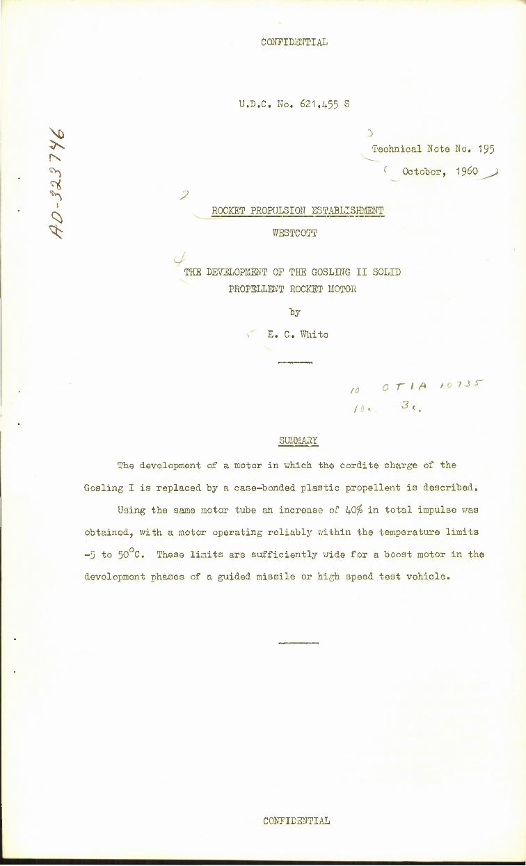
The development of a motor in which the cordite charge of the
Gosling I is replaced by a case-bonded plastic propellent is described.
Using the same motor tube an increase of hfiffo in total impulse was
obtained, with a motor operating reliably within the temperature limits
-5 to 50 C. These limits are sufficiently wide for a boost motor in the
development phases of a guided missile or high speed test vehicle.
CONFIDENTIAL
CONFIDENTIAL
LIST OP CONTENTS
1 INTRODUCTION
2 MOTOR DESIGN
2.1 Empty components
2.2 Propellent charge
2.3 Igniter
3 DEVELOPMENT STATIC FIRINGS
4 PROJECTION FIRINGS
5 CONCLUSIONS
LIST OF REFERENCES
ADVANCE DISTRIBUTION
APPENDICES I AND II
TABLES I TO III
ILLUSTRATIONS Fig. 1 to 7
DETACHABLE ABSTRACT CARDS
LIST OF APPENDICES
Appendix
I Leading physical and internal ballistic characteristics of Gosling II motor
Technical Note No.195
Page
3
3
k
h
k
5
5
5
6
7
8-9
10-12
II
Table I
II
III
Characteristics of propellent RD 2304G
LIST OF TABLES
Versions of Gosling II motor for missile boost or vehicle application and numbers supplied
Burning rates of propellent RD 2304G
Static firing results
LIST OF ILLUSTRATIONS
8
9
10
11
12
Assembly of Gosling II motor
Charge design CD 43
Metal housed igniter
Tubular igniter
Typical pressure-time curves
Typical thrust-time curves
Variation of mean thrust, pressure and burning time with operating temperature
Figure
1
2
3
4
5
6
- 2 -
CONFIDENTIAL
per missile set
Demon 8 Mayfly III 4 Mayfly IV k Gosling I k
CONFIDENTIAL
Technical Note No. 195
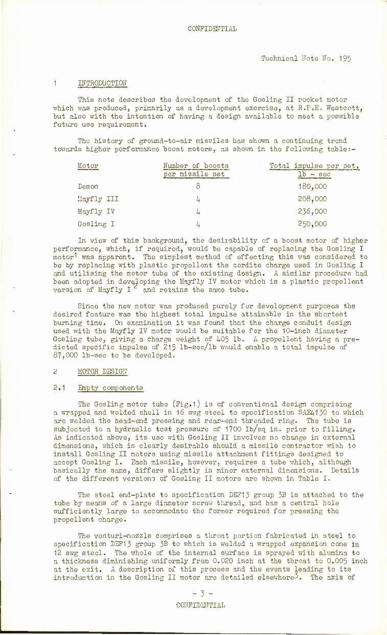
1 INTRODUCTION
This note describes the development of the Gosling II rocket motor which was produced, primarily as a development exercise, at R.P.E. Westcott, but also with the intention of having a design available to meet a possible future use requirement.
The history of ground-to-air missiles has shown a continuing trend towards higher performance boost motors, as shown in the following tables-
Motor Number of boosts Total impulse per 3et, lb - sec
180,000
208,000
236,000
250,000
In view of this background, the desirability of a boost motor of higher performance, which, if required, would be capable of replacing the Gosling I motor'' was apparent. The simplest method of effecting this was considered to be by replacing with plastic propellent the cordite charge used in Gosling I and utilising the motor tube of the existing design. A similar procedure had been adopted in developing the Mayfly IV motor which is a plastic propellent version of Mayfly I and retains the same tube.
Since the new motor was produced purely for development purposes the desired feature was the highest total impulse attainable in the shortest burning time. On examination it was found that the charge conduit design used with the Mayfly IV motor would be suitable for the 10-inch diameter Gosling tube, giving a-charge v/eight of 405 lb. A propellent having a pre- dicted specific impulse of 215 lb-sec/lb would enable a total impulse of 87,000 lb-sec to be developed.
2 MOTOR DESIGN
2.1 Empty components
The Gosling motor tube (Fig.1) is of conventional design comprising a wrapped and welded shell in 16 swg steel to specification SAE4130 to which are welded the head-end pressing and rear-end threaded ring. The tube is subjected to a hydraulic test pressure of 1700 lb/sq in. prior to filling. As indicated above, its use with Gosling II involves no change in external dimensions, which is clearly desirable should a missile contractor wish to install Gosling II motors using missile attachment fittings designed to accept Gosling I. Each missile, however, requires a tube which, although basically the same, differs slightly in minor external dimensions. Details of the different versions of Gosling II motors are shown in Table I.
The steel end-plate to specification DEF13 group 3B is attached to the tube by means of a large diameter screw thread,, and has a central hole sufficiently large to accommodate the former required for pressing the propellent charge.
The venturi-nozzle comprises a throat portion fabricated in steel to specification DEP13 group J>B to which is welded a wrapped expansion cone in 12 swg steel. The whole of the internal surface is sprayed with alumina to a thickness diminishing uniformly from 0.020 inch at the throat to 0,005 inch at the exit, A description of this process and the events leading to its introduction in the Gosling II motor are detailed elsewhere3. The axis of
- 3 - CONFIDENTIAL
CONFIDENTIAL
Technical Note No. 195
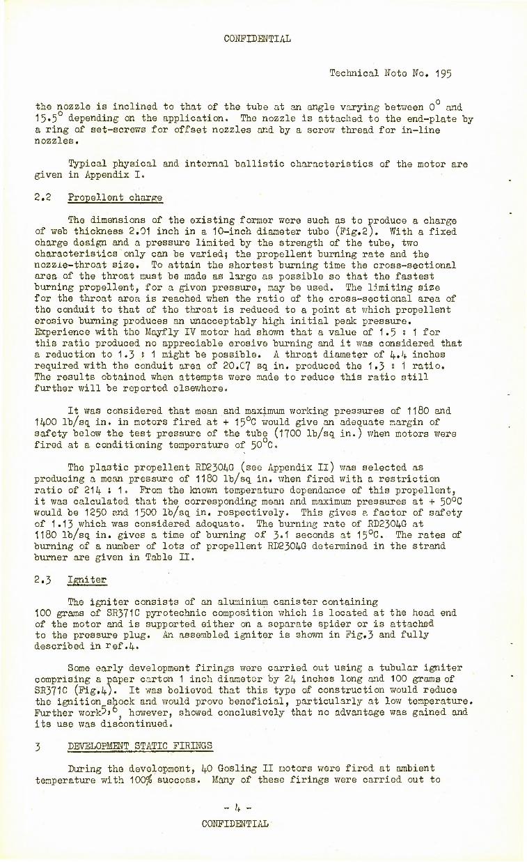
the nozzle is inclined to that of the tube at an angle varying between 0 and 15»5 depending on the application. The nozzle is attached to the end-plate by a ring of set-screws for offset nozzles and by a screw thread for in-line nozzles.
Typical physical and internal ballistic characteristics of the motor are given in Appendix I.
2.2 Propellent charge
The dimensions of the existing former were such as to produce a charge of web thickness 2.01 inch in a 10-inch diameter tube (Fig.2). With a fixed charge design and a pressure limited by the strength of the tube, two characterisiics only can be varied5 the propellent burning rate and the nozzie-throat size. To attain the shortest burning time the cross-sectional area of the throat must be made as large as possible so that the fastest burning propellent, for a given pressure, may be used. The limiting size for the throat area is reached when the ratio of the cross-sectional area of the conduit to that of the throat is reduced to a point at which propellent erosive burning produces an unacceptably high initial peak pressure. Experience with the Mayfly IV motor had shown that a value of 1.5 s 1 for this ratio produced no appreciable erosive burning and it was considered that a reduction to 1.3 s 1 might be possible. A throat diameter of 4*4 inches required with the conduit area of 20.C7 sq in. produced the 1.3 I 1 ratio. The results obtained when attempts were made to reduce this ratio still further will be reported elsewhere.
It was considered that mean and maximum working pressures of 1180 and 1400 lb/sq in. in motors fired at + 15°C would give an adequate margin of safety below the test pressure of the tube (1700 lb/sq in.) when motors were fired at a conditioning temperature of 50 C.
The plastic propellent. ED23Q4G (see Appendix II) was selected as producing a mean pressure of 1180 lb/sq in. when fired with a restriction ratio of 214 s 1» From the known temperature dependence of this propellent, it was calculated that the corresponding mean and maximum pressures at + 50°C would be 1250 and 1500 lb/sq in. respectively. This gives a factor of safety of 1.13 which was considered adequate. The burning rate of RD2304G at 1180 lb/sq in. gives a time of burning of 3«1 seconds at 15°C. The rates of burning of a number of lots of propellent RD2304G determined in the strand burner are given in Table II.
2.3 Igniter
The igniter consists of an aluminium canister containing 100 grams of SR371C pyrotechnic composition which is located at the head end of the motor and is supported either on a separate spider or is attached to the pressure plug. An assembled igniter is shown in Fig.3 and fully described in ref .4.
Some early development firings were carried out using a tubular igniter comprising a paper carton 1 inch diameter by 24 inches long and 100 grams of SR371C (Fig.4). It was believed that this type of construction would reduce the ignition shock and would prove beneficial, particularly at low temperature. Further work5>° however, showed conclusively that no advantage was gained and its use was discontinued.
3 DEVELOPMENT STATIC FIRINGS
During the development, 40 Gosling II motors were fired at ambient temperature with 100$ success. Many of these firings were carried out to
- 4 -
CONFIDENTIAL•
CONFIDENTIAL
Technical Note No. 195
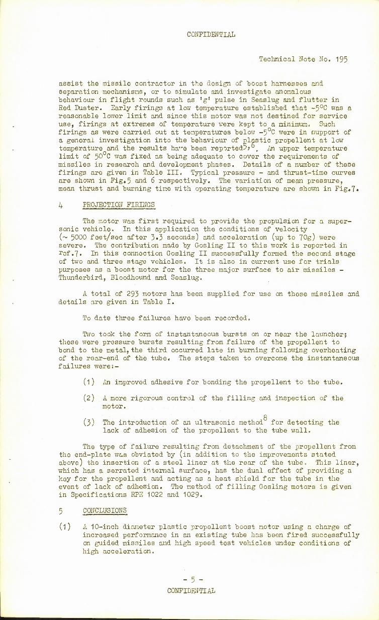
assist the missile contractor in the design of boost harnesses and separation mechanisms, or to simulate and investigate anomalous behaviour in flight rounds such as 'g' pulse in Seaslug and flutter in Red Duster. Early firings at low temperature established that -5°C was a reasonable lower limit and since this motor was not destined for service use, firings at extremes of temperature were kept to a minimum. Such firings as were carried out at temperatures below -5°C were in nupport of a general investigation into the behaviour of plastic propellent at low temperature and the results ha-e been reported5?°. An upper temperature limit of 50 C was fixed as being adequate to cover the requirements of missiles in research and development phases. Details of a number of these firings are given in Table III. Typical pressure - and thrust-time curves are shown in Fig.5 and 6 respectively. The variation of mean pressure, mean thrust and burning time with operating temperature are shown in Pig.7.
4 PROJECTION FIRINGS
The motor was first required to provide the propulsion for a super- sonic vehicle. In this application the conditions of velocity (~ 5000 feet/sec .after 3»3 seconds) and acceleration (up to 70g) were severe. The contribution made by Gosling II to this work is reported in rof.7« In this connection Gosling II successfully formed the second stage of two and three stage vehicles. It is also in current use for trials purposes as a boost motor for the three major surface to air missiles - Thunderbird, Bloodhound and Seaslug.
A total of 293 motors has been supplied for use on these missiles and details aro given in Table I.
To date three failures have been recorded.
Two took the form of instantaneous bursts on or near the launcher; these were pressure bursts resulting from failure of the propellent to bond to the metal, the third occurred late in burning following overheating of the rear-end of the tube. The steps taken to overcome the instantaneous failures weres-
(1) An improved adhesive for bonding the propellent to the tube.
(2) A more rigorous control of the filling and inspection of the motor.
Q
(3) The introduction of an ultrasonic method for detecting the lack of adhesion of the propellent to the tube wall.
The type of failure resulting from detachment of the propellent from the end-plate was obviated by (in addition to the improvements stated above) the insertion of a steel liner at the rear of the tube. This liner, which has a serrated internal surface, has the dual effect of providing a key for the propellent and acting as a heat shield for the tube in the event of lack of adhesion. The method of filling Gosling motors is given in Specifications RPE 1022 and 1029.
5 CONCLUSIONS
(l) A 10-inch diameter plastic propellent boost motor using a charge of increased performance in an existing tube has been fired successfully on guided missiles and high speed test vehicles under conditions of high acceleration.
- 5 - CONFIDENTIAL
CONFIDENTIAL
Technical Note Wo. 195
(2)
(3)
The advantages of plastic propellent are such as to increase the total impulse by 2A,500 lb-sec, or l+Ofo over Gosling I. This increase is gained by greater loading density (approx 29$ more propellent) and higher specific impulse (about Qfo)of the propellent.
The motor ignites and performs reliably within the temperature limits -5 to +50°C.
REFERENCES
No. Author
1 Dickinson, L.A. Morris, N..J.
Title, etc.
The development of the cordite-filled Gosling I boost motor (to be published)
2 Dickinson, L.A. The development of the Mayfly I boost motor and its variants R.A.E. Tech.Memo.No. RPD1A9 November 1957
3 White, E.C. Solid propellent rocket motorss thermal insulation of nozzles, Part I R.A.E. Tech.Memo.No. RPD122. April 1957
4 Crook, J.H. Harrison, E.G.
Ignition of solid propellent rocket motors for guided weapons R.A.E.Tech.Memo.No. RPD119 January 1957
5 Hirst, R.C. The behaviour of plastic propellents in rocket motors at low temperatures R.A.E.Tech.Note No. RPDI58 November 1957
Rolfe, J.A. White, E.C.
Investigation of factors involved in the failure of plastic propellent motors at low temperature R.P.E.Tech.Note No.180 May 1959
Picken, J. Notes on the progress of free flight trials to measure heat transfer at Mach numbers up to 5 R.A.E.Tech.Note No. Aero 2575 June 1958
8 Lister, R. An ultrasonic method of detecting lack of adhesion between case-bonded plastic propellent and the tube wall in rocket motors R.A.E.Tech.Note N0.RPDI56 November 1957
- 6 -
CONFIDENTIAL
CONFIDENTIAL
Technical Note No. 195
ATTACHED;-
Appendices I and II Tables I to III Drgs.No, RP 2837-2840 Detachable abstract cards
ADVANCE DISTRIBUTIONi-
MOA
CGWL CM DG/GW D/GW(Air) D/GW(N) D/GW(Tech) DIKED DI Arm
AD/GW (P & W) AD/MXRD (X) ADSR (Records) D/ERDE 3 RAE Farnborough 5 Sec EDPC GW(A)l(b) 70 TIL 1(b) 100
- 7 -
CONFIDENTIAL
CONFIDENTIAL
Technical Note No. 195
APPENDIX I
Leading physical and internal ballistic characteristics
of Gosling II motor
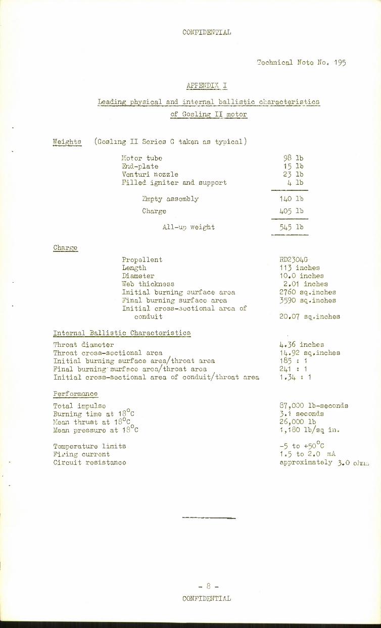
Weights (Gosling II Series G taken as typical)
Charge
Motor tube End-plate Venturi nozzle Pilled igniter and support
Empty assembly
Charge
All-up weight
Propellent Length Diameter Web thickness Initial burning surface area Final burning surface area Initial cross-3ectional area of
conduit
Internal Ballistic Characteristics
Throat diamoter Throat cross-sectional area Initial burning surface area/throat area Final burning surface area/throat area Initial cross-sectional area of conduit/throat area
Performance
Total impulse Burning time at 18 C Mean thrust at 18°CO
Mean pressure at 18 C
Temperature limits Firing current Circuit resistance
98 lb 15 lb 23 lb 4 lb
140 lb
405 lb
545 lb
RD2304G 113 inches 10,0 inches 2,01 inches
2760 sq..inches 3590 sq.inches
20.07 sq.inches
4«36 inches 14.92 sq.inches 185 ? 1 241 : 1 1.34 s 1
87,000 lb-seconds 3.1 seconds 26,000 lb 1,180 lb/sq in.
-5 to +50°C 1.5 to 2.0 mA approximately 3.0 oliu
- 8 -
CONFIDENTIAL
CONFIDENTIAL
Technical ITote No. 195
APPENDIX II
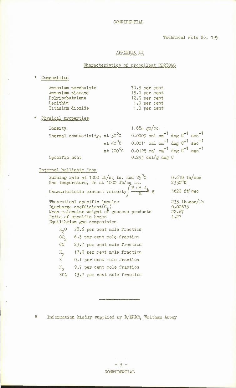
Characteristics of propellent RD2304G
Composition
Ammonium percholate 70.5 per cent Ammonium picrate 15»0 per cent Polyisobutylene 12.5 per cent Lecithin 1,0 per cent Titanium dioxide 1.0 per cent
* Physical properties
Density 1.684 gm/cc i i i
Thermal conductivity, at 30 C 0.0009 cal cm' deg C sec
at 60 C 0.0011 cal cm- deg C~ sec
at 100°C 0.0125 cal cm"1 deg C-1 sec"1
Specific heat 0.293 cal/g deg C
Internal ballistic data
Burning rate at 1000 lb/sq. in. and 25 C 0.610 in/sec Gas temperature, Tc at 1000 lb/sq. in. 2350°K
(Pdt A, 1 Characteristic exhaust velocity; JJ—* g 4620 fV sec
Theoretical specific impulse 233 lb-sec/lb Discharge coefficient(O 0.00675 Mean molecular weight or gaseous products 22.67 Ratio of specific heats 1.27 Equilibrium gas composition
H_0 28.6 per cent mole fraction
COp 6.3 per cent mole fraction
CO 23.7 per cent mole fraction
H0 17»9 per cent mole fraction
H 0,1 per cent mole fraction
Np 9«7 per cent mole fraction
HC1 13.7 per cent mole fraction
* Information kindly supplied by D/ERDE, Waltham Abbey
- 9 -
CONFIDENTIAL
CONFIDENTIAL
Technical Note No. 195
a
3D •H H P,
& cn
CD H CD
§ B o
•H +> Oj O
•H rH P. fi- ri
o rH o
•H
0) > rH o
+' 0) o o
CD H •H ra
H O
*H
H O +' O B
H
a a) O
03
I u o >
^-^ >> rH -r- N
rQ d *—' -p C~- (M vo -tf CN CVJ CVJ ^— K>
-rl o LfN T— LTi -4" S ON a) EH T— CVJ
•H rH P. P. 3 U CQ CD
-p CQ
O to O O CO O Jt CO CJ o OJ +» Tj T— -4- LfN CM -4- o •H ^— a A
=H O h rH « CD
rg &q t"~ C\J CO -+ LTN -* o n— T—
& £ -4" VD OJ \r\
M
U CQ CD 0) <H bD to CJ
•H •~s cd H3
EH •p CD
O EH
•s a 1 CQ •p r^ 3 CO
rH rH i o
CD o CD « o
o Wv 0 -P
cd CO
CO
£ (S B a o o o •H •s *H o -P u > o rt CD H 00 o jd Tj
•H r-l ft
-p E H O
&0
ft ft o •H o •3«
m o
rH o
>
© •-5
o rH o
•H ,3 O >
•tj TJ
EH
o rH O
•H ,.C1 O >
3"»\
o rH O
•H XI o >
o 0 u TTl fH 0 o •H •H •H rt •H •H •rH O d C XJ T rD g S rH o o fH 0 M fH O O O CQ CD O jd 3 O CQ CQ -H fH U TJ -a rH TJ fH fH X) CD a c o CQ r^ CD CD 0 ft ft P o a 3 ft ft > 3 p £ rH o 5 3 3
CQ CQ pq m EH CQ CO
O
•t
(1) •H rH
-P 3 w|c\i H|N ir>
O o LT\ T- m -3- LO o C 1— •*— •v— ^— 0) -P o > O •4-
CQ <H «H o
O n H o •-3 w a fe fH o CQ -p 0) o •H a ?H
CD CO
O
u w
Cc3
+s CO is •n -p CO
00
g o
s -p 00 a
•H
I
O
1
00 0
+» o
|25
!£•
fH H^> CD CQ
XJ O O O
S -° Cd Cy
rH O
O S CD
|a 3 CD
m -P 3 CQ
° b
+= rH
CQ CD a xi
•H -P
0 CD c c o o
oo CD
(M
-•10 -
CONFIDENTIAL
CONFIDENTIAL
Technical Note No. 195
TABLE II
Burning rates of propellents RD2304A and RD2304G
Propellent formulation
KD2304A * RD2304G *
Lot No.
Rate, in/sec
Lot No.
Rate, in/sec
Lot No.
Rate, in/sec
Lot No.
Rate, in/sec
Lot No.
Rate, in/sec
1 0.597 'I 0.613 15 0.603 29 0.602 43 0.604
2 0.601 2 0.616 16 0.613 30 0.616 44 0.601
3 0.605 3 0.620 17 0.617 31 0.617 45 0.611
4 0.627 4 0.619 18 0.611 32 0.605 46 0.608
5 i 5 0.610 19 0.616 33 0.610 47 0.613
6 0.637 6 0.613 20 0.610 34 0.614 48 0.614
7 0.628 7 0.616 21 0.605 35 0.607 49 0.607
8 0.617 22 0.610 36 0.611 50 0.607
9 0.617 23 0.611 37 t 51 0.607
10 0.607 24 0.605 38 0.605 52 *
11 0.605 25 0.601 39 0.608 53 0.608
12 0.612 26 0.611 40 0.607 54 0.604
13 0.613 27 0.608 41 0.602
14 0.602 28 O.605 42 0.610
0
Propellents RD2304A and RD2304G are identical in every respect; the change of nomenclature arose from confusion resulting from a clerical error. All propellent was made at R0F Bridgwater.
These lots were re-blended.
All "burning rates were determined at R0P Bridgwater or at RPE on strands 4»5 n• diameter at 1000 lb/sq in.
- 11 -
CONFIDENTIAL
ON
O to ©
o •H
o ©
3 5
CO -p i n ©
o o
9 6-i
U H
«H
O •rH +» d -p CO
B M
pq
Initial peak pressure
/ choke firing
Instrumentation failed
q •rt
So
-d 1 o
in: = ft s SSBBSBBSSBEBSSSESBSBBBSSSSSBSBSSEBSSEB o= = s l <3 tr\
si! Boo1
•rj I «D M PS. a PXrH
O0^O0O0OOO0O0O^^^'- g^00 0\t^OW^rC0OOm«QcOONC0OQO4^OOQOO t-ONVOO r lAh-lA(\lK>0\OIAW »- t^lAJ- 2 r~t-Cf\00 h-lAIAVO J-O >A W l°l« W5 K> lAr--O\C0 CO 00 t\l (\l O CMTin -4 to en CM CM -4 m -4-4 -4 CM in-4 CM jmm-J £ -»*^^^^^^^^^-'*^^^^^^-4-m^mmmminLn-4in
•p o
Mean
thrust,
lb
OOOOQOQOOOQOOQOOOOOQQOQOOOOQQQQQOQQOOQOOOOO Q Q Q OOOOOQOOOOOOOOOOOOQOOOOOOOOOQC5OOOOOc0V00r--voOC\jO . QOO wr^vor-^o ONVJTii^vo j-t-iri44r-Of^c-0(MO^(MT-vo o N4vo CMACXI IT\T-ONVC r~o inc\i 1 O mCM
in^-mo IA^O invc<^o t~-ir>vo vo mvo vo c-t~-t-JIAVO mm-t^o o IAVO in-^irnrwo J-invo invovo vo mm o^ooo C\JC\JC\1C\1C\JC\JCUC\JC\JC\JC\JC\JC\JC\JC\JCVCJC\IC\JC\JC\^ I^WN
Speoific
impu
lse,
lb-sec/lb
mo^vovoaDvooooo^c^wojot-r-r-io^cMT-c^om^co^oocoo^commooNONOcoow w ri^ T-^(MC^V-^T-T-CMCM'«-C\JCM'»-(MT-C\JCMCMOC\J<MT-CMT-'<-V-T-CMC\JT- CMT-T-V-T-C\)V-T-CMT-CM'«- 1 CM •»- CM CM C\J CM i- CMC\l<MCMCMCMCUCMCMC0CMC\JC\IC\,C\iOJCNJC\JCMCMCM<MC\ICMCMCMC\JW CVJ CM CM
Total
impulse,
lb-sec OOOOOOOOOQOOOOOOOOOOOOOOOOOOOOQOQQQOOOQOOOO QOO
OOOccmmooOOOOOOOOOOOOOOOOQOOOOOOQOOQmcovoa5t^COC--C-- OOO O\j-vomv3coc\icj\mj-moco CA-to>vovom\o mc\im-toomo^omi~-c5oc^a\covoco o\mmco -t I CM c^- in
cooooc^Jco^-mcoc^ocoo^co^-cocoo^o^6cJO^c^cooovocor~^-C!^c^coo^o^co mcoco r>co CNCOCO cr\ i- -4 o-\ coroo>t^cococococooNcococococo»cococ^cOcocococococ'' co cocococccococococOcoajcococococo cr\ oo co
Burning
time
* seconds
coa3r-mt^coint-iAO^T-wov)044-o\woT-vococomfAnri^c\iwcocoi^t-covor-vowoow^
^^f^fommmmmmmmmmmmmmmmmmmmmmmmm CM CM CM
.Ign
itio
n delay,
second in
WW«4444^CA4lAi0^44444-wrgNWW^inJ^4vo^^Ot-^r'OC0^4^'5 0C\0!OW2} •r-OOOOOOOOT-OOOOOOOOOOOOOOOOOOOOOT-OOT-T-OOOOO'r-O'r-OOO
OOOOOOOOOOOOOOOOOOOOOOOOOOOOOOOOOOOOOOOOOOOOOOO
Igniter
housing
rrj rrj Tj "d © .^-x © © © B: s r- CQ= BSESBESESEEBSEBSBSBSESEBEBS m -
5 ~ § I 1 crj p rt^ _ 3 _ __.fl,_________-_. .... ......... - ? <ti _ <D~ ~ "B ~ ~ <D~ p~ " ~ ' 0~ 3© m e to e a sa
Charge we
ight
,
lb oz COCOjT-^NW-JOO'OOWWJ'OOOCOIAOOOOCOOCOWOWnJOoacoeOOOOOODOOOCOO^fO
vo io r-cy vo vo vo *o t-vo J-OJI^CO CM f-vo \o mw mmwwwmc^mwp^mr^'>ot-»oc\in,icvmr-mwo^)»-wc\j OOOT-OOOOOOOOOOOOOOQOOOOQQQC^OQOQQQQQQOOQO ^5^-4^^-4-4 4-^-4-4^^4-^4-.4-4-4-4.4-4-4-4-4m-4-4-4-4-4-4.4-4^-4^-4-4-4.-4.4-4^
-p
g ©
g
o to •p
rH
in CM-4-vo 9^ CM -4-4-4-4VO oo O O invovo )0 _4 0Jmm4 4
T-OOIt— COONCTNT-T-i-CMrOt— t-«8 ^C^OOT- . onO O W C\J CO CM mvO IO
T- mmmf-o\c\T-44^t co CM CM c--•«--* in CM •< £« o o
•H
•rH CQ
r?
o o o o o o rAws foe E s e r s ms = s s 10: rrssssrss = fcsssse = EErEE = s = s mE ms
© •P
r— co oo inr—r~r—r-—c—t—c--r--c—oo cocooooococo cr\co co ON O o\o>.c7\o\CTNCTNcr\cr\ON o o CNCAONONCTNO O C—r—COCO mmmmmmmmmmmmmmmmmmmmmmminvo minmiriirimirnrMAvoV) in in in in in >o >o mmmm
inT-T-oi^^wi^inint^t>-t^T-T-^t^cy\o>T-T-cucM'^-^ *— T- *- T- T" <r» • . T- . T" . T» t" *""
ost^c^c\jo\c^.4cocTNcr\u^inu^^'r-oocomr^vocNJr^inT- • moo o vo mm T-T-T- CM CM W CM ffMTMA T- CM «- CM T- rAc\lr-r-cy)r-^rr'MnT-lOn,lT-r»0i
Round
No.
COT-CMr-int—T-incO«-CMVO CM T- CM t^\ OMTiVOVO
e-i^mmoioci\Q<yvO^' t^-cop-cOrrMOrAcvi 4iAcocf\4 4c\iQQr^O r-mof- *- CM CM cywovo mmr~co^OT-T-i-cocoT-wiom«cococooNOriAmvot^m^c>T.c\ik to to to
H "EBESK PHSSSSEBSeESBSEESESSSSSECSBESSESSBSBEiq Q toN4 EEE O H R H H O »~ M H M H r-
-p
© o 3 8 •H •P •H ffi o
o
O © -P o
p<
ro
M co
g
-p •H
•P rt
n ©
bj N O C
©
©
A o
3 ro
8 J3 -P
© © a +» fl +» rt -H
<rl.
©
03 E © a i
•p o 6
si ^
•H
-p n5
TJ ©
©
©
O X! -P
-P -P O O -P CQ ©
-P
©
1 U P<
a> 5 ©
s
i CD
•P
R P 2837 CONFIDENTIAL RPE T.N. 195 FIG. I
O o 2 "* a = fi
•**
-I < §z in o If
u z
a H UJ
<
s5
s o ..
UJ
< a
-I _, UJ a
£ £ - => a a u> h- III ui t- z > > 3 ui O O O >
a O O 2
1=1 o z -J l/> o
ffl
UJ to
<
O a.
R P 2838 CONFIDENTIAL RPE T.N 19 5 FIG. 2t3
0-66 RAD.
FIG.2 CHARGE DESIGN C D 43
FIG. 3 METAL HOUSED IGNITER
R P 2839 CONFIDENTIAL RPE T.N. 19 5
Fl G.4
CM
in
in
CM
</) UJ M 3 u- U ct t- U LU _l UJ
LL
O
z o I- < u o
z o <J
1- r» — <n W
O a a 2
m
O u. u O
UJ 2 t- o z O (3 O
in
r- CM
R P 2840 CONFIDENTIAL P. PE T.N. 195
FIG. 5, 6, & 7
ipoo
PRESSURE, Lk/SO IN • 50 *C
AIR -S*C
1,000
GOSLING n MOTOR PROPELLENT RD 2304 G NOIILE THROAT DIA. 4-36"
3 4 BURNING TIME, SECONDS
FIG. 5 TYPICAL PRESSURE - TIME CURVES
THRUST, L6 40000
JOOOO
4-0 SO BURNING TIME, SECONDS
FIG.6 TYPICAL THRUST- TIME CURVES
1.4.00, 2B.OOO
PRESSURE, LSfSQ IN -
(OOO. 20,000.
BOO 16.000
GOSLING D MOTOR PROPELLENT RD 2304 G NOZZLE THROAT DIA 4-36"
10 20 30
TEMPERATURE. °C
3 S
BURNING TIME. SECONDS
30
2 5
20 SO
FIG. 7 VARIATION OF MEAN PRESSURE, TH RUST & BURNING TIME WITH OPERATING PRESSURE

CONFIDENTIAL
i
CONFIDENTIAL