Embed Size (px)
Citation preview
I I I I iIII
.......,...
CO User's Guide
to Calibration of
Pneumatic Controllers
in Heating, Ventilating,
and Air Conditioning
(HVAC) Systemsby
R. vim
-r
Sponeored by:Naval FacUlitles Engineering Command Navel Civil Engineering LaboratoY
Alexandra. Virginia 22332 Port Hueneme. California 93043
Li AP111:iic relec sem.. . ..' , _, . . . . . - .
Ditr~~t 0 ~Unlimiteod
89 12 26 058
CONTENTS
Page
DEFINITIONS .... ................ . ...
GENERAL PROCEDURE ...... ............. 6
Single-Input Controllers ... ....... 7Calibration Procedure for
Single-Input Controllers 10..... 0Dual-Input Controllers ......... ... 13Calibration Procedure for
Dual-Input Controllers . ...... . 20
LIST OF FIGURES
Figure 1. Typical single- and two-inputpneumatic controllers . . . . 2. .
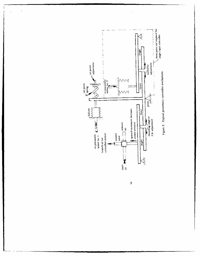
Figure 2. Typical pneumatic controller
mechanism .. .......... . 3
Figure 3. Illustration on controllernomenclature .. .......... By
Figure 4. Illustration of sensor L.,:- .*
nomenclature . ........ .. 5
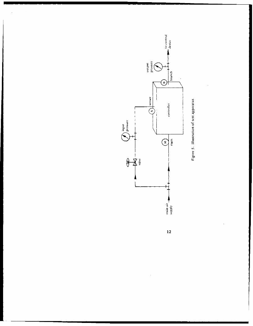
Figure 5. Illustration of test D .;Aapparatus .... .......... 12 t
Figure 6. Application of two-inputcontroller . ......... . 16 i.
Figure 7. Reset schedule .. ......... ... 17
iii
DEFINITIONS
The calibration of proportional pneumaticcontrollers (Figures 1 and 2) requires knowledge
of at least three things: the controller action,
the setpoint, and the throttling range.
Action. A controller is either directacting or reverse acting. In a direct acting
controller, an increase in the input pressure tothe controller results in an increase in the
output pres: ire from the controller. In areverse acting controller, an increase in the
input pressure results in a decrease in output
pressure.
Setpoint. The value to which the control
point setting mechanism is set. For example, a
temperature controller iuighhL be set at 751F.
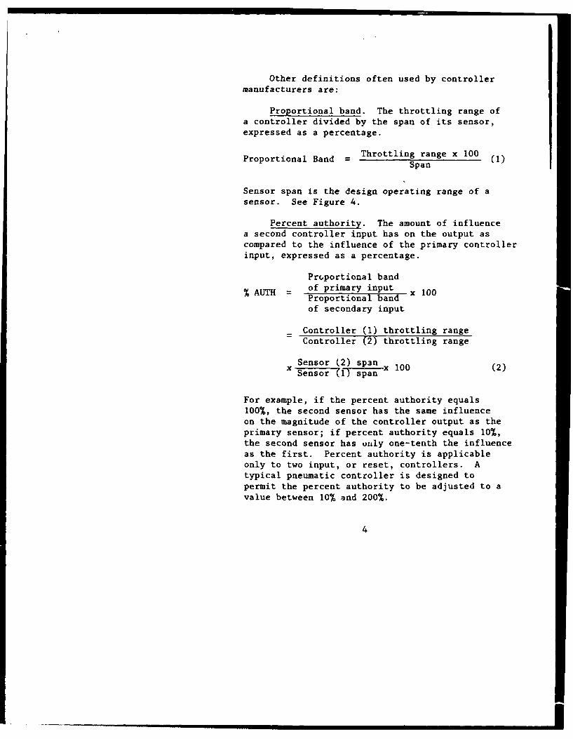
Throttling range. The change in the inputvariable required to produce the maximum change
in the output variable. For example, if a
change of 4'F at the input sensor of a singleinput temperature controller results in the fullrange of controller output pressure, the throttlingrange is 4'F. See Figure 3.
I
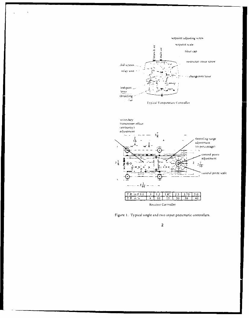
setpoint adjusting screw
.ctpoint scale
filter cap
_ _ _ restrictor cover screwdial screws /
relay unit - a I
"*'' -- changeover lever
leakport -lever
throttling
Typical Tcmperature Controller
secondarytransmitter effectiauthoritv)adjustment
5-'
31 throttling range
- - 3 adjustment8 (in percentage)
S __control point
-I * adjustment
3 IL6I
-3-
T.R in P S.I. .5 1.2 1.87 2.5 3.75 5.0TRin% 4 10 15 20 30 40
Receiver Covtroller
Figure 1. Typical single and two input pneumatic controllers.
2
C40
c0o
.,.-
rS
.-K . .
LIti m i
2~
uc0
jq0
Other definitions often used by controllermanufacturers are:
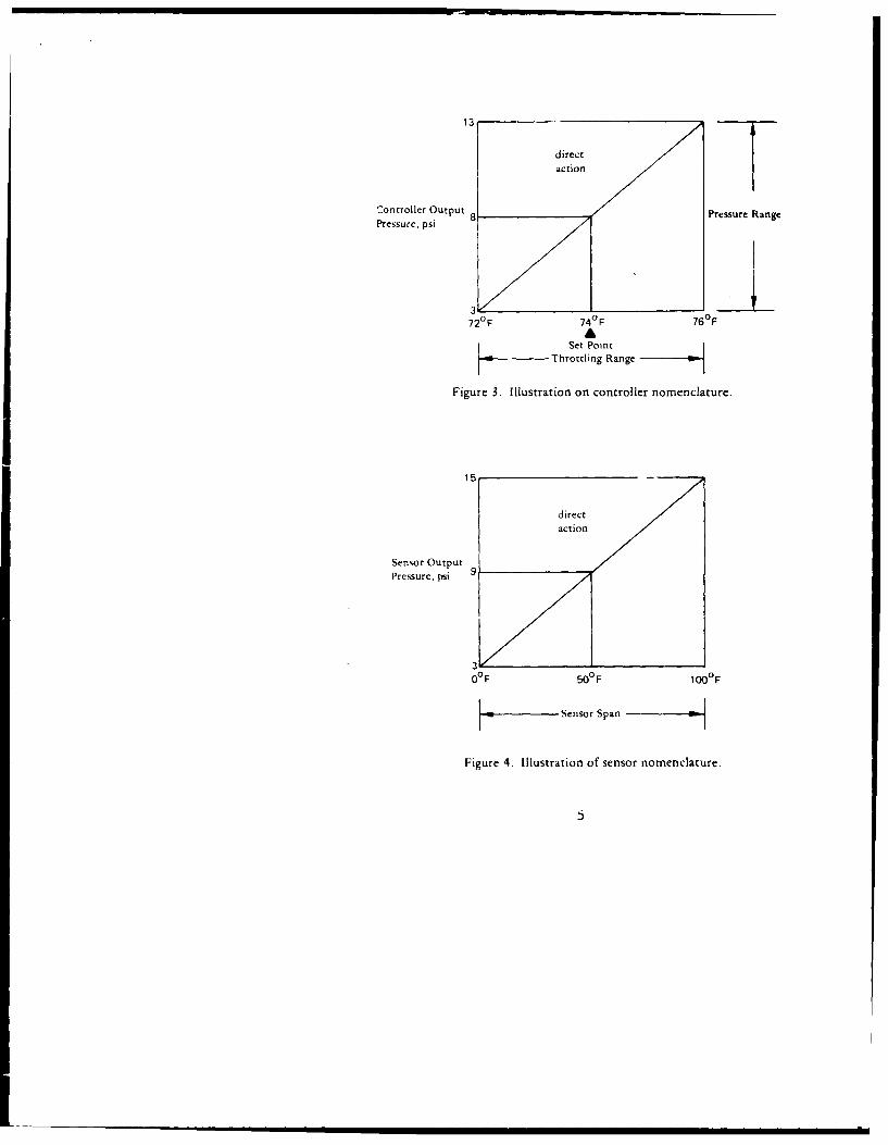
Proportional band. The throttling range ofa controller divided by the span of its sensor,expressed as a percentage.
Proportional Band = Throttling range x 100 (1)Span
Sensor span is the design operating range of asensor. See Figure 4.
Percent authority. The amount of influencea second controller input has on the output ascompared to the influence of the primary controllerinput, expressed as a percentage.
Proportional band
% AUTH of primary input X 100Proportional bandof secondary input
Controller (1) throttling rangeController (2) throttling range
Sensor (2) span 00 (2)x Sensor (1) span x 1
For example, if the percent authority equals100%, the second sensor has the same influenceon the magnitude of the controller output as the
primary sensor; if percent authority equals 10%,the second sensor has unly one-tenth the influenceas the first. Percent authority is applicableonly to two input, or reset, controllers. A
typical pneumatic controller is designed topermit the percent authority to be adjusted to avalue between 10% and 200%.
4
direct
Controller Output 8 Pressure RangePressure, psi
3V72'F 74
° F 76°FA
Set PointThrottling Range
Figure 3. Illustration on controller nomenclature.
15
directaction
Sensor OutputPressure, psi 9
3Z
O°F 50°F I00°F
I -Sensor SpanI -
Figure 4. Illustration of sensor nomenclature.
• . i l l l I5
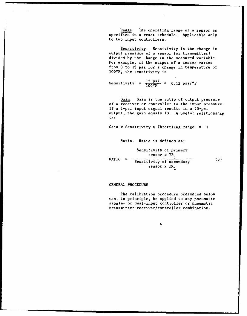
Range. The operating range of a sensor asspecified in a reset schedule. Applicable onlyto two input controllers.
Sensitivity. Sensitivity is the change inoutput pressure of a sensor (or transmitter)divided by the Lhange in the measured variable.For example, if the output of a sensor variesfrom 3 to 15 psi for a change in temperature of100*F, the sensitivity is
Sensitivity 12 psi 0.12 psi/F
Gain. Gain is the ratio of output pressureof a receiver or controller to the input pressure.If a 1-psi input signal results in a 10-psioutput, the gain equals 10. A useful relationshipis:
Gain x Sensitivity x Throttling range = 1
Ratio. Ratio is defined as:
Sensitivity of primarysensor x TR1RATIO = )
Sensitivity of secondarysensor x TR2
GENERAL PROCEDURE
The caiibration procedure presented belowcan, in principle, be applied to any pneumaticsingle- or dual-input controller or pneumatictransmitter-receiver/controller combination.
6
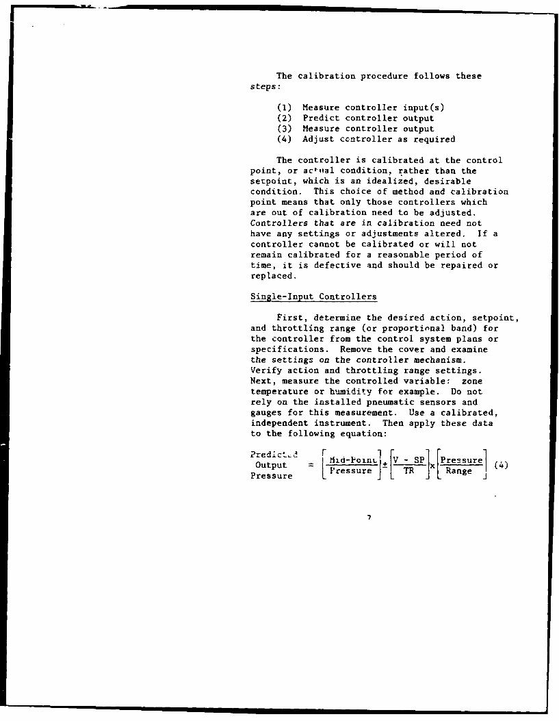
The calibration procedure follows thesesteps:
(1) Measure controller input(s)(2) Predict controller output(3) Measure controller output(4) Adjust ccntroller as required
The controller is calibrated at the controlpoint, or actual condition, rather than thesetpoint, which is an idealized, desirablecondition. This choice of method and calibrationpoint means that only those controllers whichare out of calibration need to be adjusted.Controllers that are in calibration need nothave any settings or adjustments altered. If acontroller cannot be calibrated or will notremain calibrated for a reasonable period oftime, it is defective and should be repaired orreplaced.
Single-Input Controllers
First, determine the desired action, setpoint,and throttling range (or proportional band) forthe controller from the control system plans orspecifications. Remove the cover and examinethe settings on the controller mechanism.Verify action and throttling range settings.Next, measure the controlled variable: zonetemperature or humidity for example. Do notrely on the installed pneumatic sensors andgauges for this measurement. Use a calibrated,independent instrument. Then apply these datato the following equation:
Output _ [id-Pon SP Pressure 4~ I TX[ Rnge
Pressure Pressure IL Range J
7
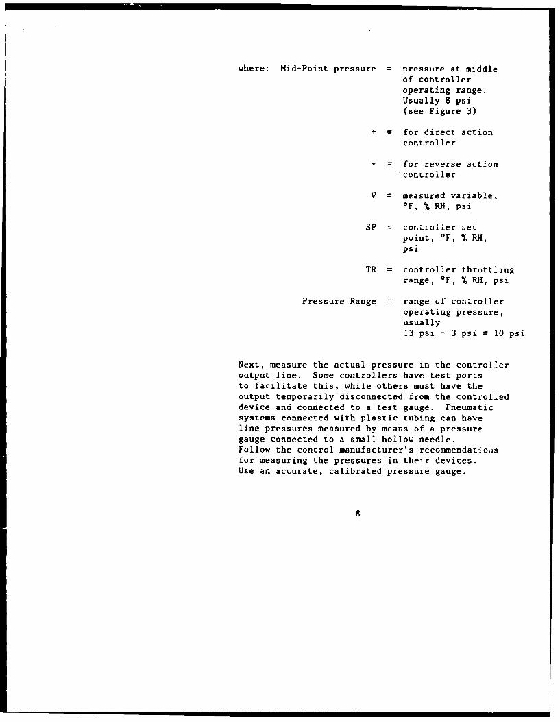
where: Mid-Point pressure = pressure at middleof controlleroperating range.Usually 8 psi(see Figure 3)
+ = for direct action
controller
= for reverse action.controller
V = measured variable,oF, % RH, psi
SP = contcoller setpoint, *F, % RH,psi
TR = controller throttlingrange, oF, % RH, psi
Pressure Range = range of controlleroperating pressure,usually
13 psi - 3 psi = 10 psi
Next, measure the actual pressure in the controlleroutput line. Some controllers have test portsto facilitate this, while others must have theoutput temporarily disconnected from the controlleddevice and connected to a test gauge. Pneumaticsystems connected with plastic tubing can haveline pressures measured by means of a pressuregauge connected to a small hollow needle.Follow the control manufacturer's recommendatiousfor measuring the pressures in their devices.Use an accurate, calibrated pressure gauge.
8
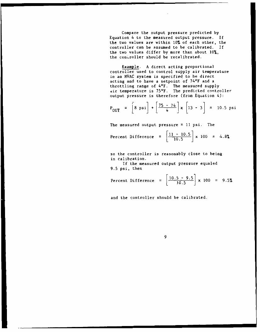
Compare the output pressure predicted by
Equation 4 to the measured output pressure. Ifthe two values are within 10% of each other, thecontroller can be assumed to be calibrated. Ifthe two values differ by more than about 10%,the conLroller should be recalibrated.
Example. A direct acting proportionalcontroller used to control supply air temperaturein an HVAC system is specified to be directacting and to have a setpoint of 74°F and athrottling range of 4°F. The measured supplyair temperature is 75°F. The predicted controlleroutput pressure is therefore (from Equation 4):
POUT = L psiJ [75 4 74]x [13 - 3] = 10.5 psi
The measured output pressure = 11 psi. The
Percent Difference = [10. x 100 = 4.8%
so the controller is reasonably close to beingin calibration.
If the measured output pressure equaled9.5 psi, then
Percent Difference = [ O9.5 x 100 = 9.5%
and the controller should be calibrated.
9
Calibration Procedure for Single-Input Controllers
First, make sure the main air supply is atthe design pressure, usually 17 to 20 psi. Ifthe main air pressure is not as specified at thedevice being calibrated, check for excessive airleakage, crimped tubing, dirty filters, a faultyor incorrectly set pressure regulator and othercauses of incorrect main air supply pressure.
A single-input pneumatic controller iscalibrated using either of the followingprocedures:
Procedure A
(1) Loosen the setpoint scale so tLat itcan rotate freely.
(2) Install calibrated pneumatic gauge inthe output (ot branch) line.
(3) Turn the setpoint adjustment screwuntil the controller output pressur-is equal to the value predicted byEquation 1.
(4) Rotate the setpoint scale until theindicated value equals the desiredsepoint.
(5) Tighten the setpoint scale.
(6) After system comes to equilibrium,compare predicted and measured valuesof output. Repeat steps 1 through 5if necessary.
10
Procedure B
(1) Disconnect the sensor (or input) linefrom the controller.
(2) Connect a calibrated pneumdtic gaugeto the input port of the controllerwith a "T" connection (see Figure 5).
(3) Connect an adjustable restriction,such as a needle valve, to the "T"connection.
(4) Connect the free end of the adjustablerestriction to the main air supply
(5) Connect a calibrated pneumatic gaugeto the output port of the controller.
(6) Adjust the restriction until the inputpressure gauge reads the value of thepressure corresponding to the desiredsetpoint. You will need data onsensor span and pressure range forthis step.
(7) Turn the setpoint adjustment screwuntil the output pressure equals themid-point pressure value (typically8 psi).
(8) Adjust the setpoint scale to read theselected value of setpoint.
11
i . l I I l
!0
12
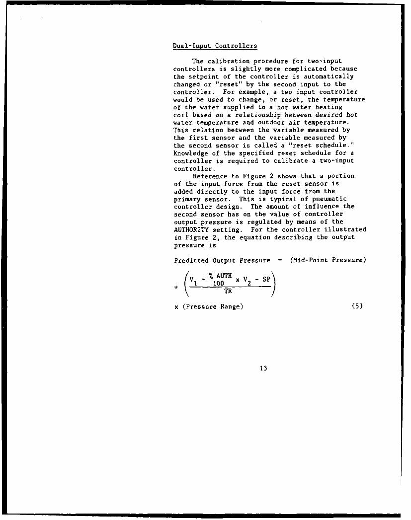
Dual-Input Controllers
The calibration procedure for two-inputcontrollers is slightly more complicated becausethe setpoint of the controller is automaticallychanged or "reset" by the second input to thecontroller. For example, a two input controllerwould be used to change, or reset, the temperatureof the water supplied to a hot water heatingcoil based on a relationship between desired hotwater temperature and outdoor air temperature.This relation between the variable measured bythe first sensor and the variable measured bythe second sensor is called a "reset schedule."Knowledge of the specified reset schedule for acontroller is required to calibrate a two-inputcontroller.
Reference to Figure 2 shows that a portionof the input force from the reset sensor isadded directly to the input force from theprimary sensor. This is typical of pneumaticcontroller design. The amount of influence thesecond sensor has on the value of controlleroutput pressure is regulated by means of theAUTHORITY setting. For the controller illustratedin Figure 2, the equation describing the outputpressure is
Predicted Output Pressure = (Mid-Point Pressure)
(V + % AUTH xV-SP)
+ ( 1 100 x V2
x (Pressure Range) (5)
13
Equation 5 is for direct action sensors (i.e.,sensor output pressure increases with an increasein the sensed variable). The branch line pressureof the controller will increase with an increasein either the primary variable (V ) or the resetvariable (V2 ). Thus, the controller describedabove can be said to have direct/direct action.The action of controllers can be changed byusing one or more reverse action sensors and, insome controller designs, by moving the positionsof the controller linkages and pivot points.Confusion and errors are minimized, however, ifonly direct action sensors are used in an HVACcontrol system and all controller actions are ofthe same type (e.g., direct/direct). If reversecontroller action is required it is best obtainedby connecting a reversing relay between thecontroller and the controlled device.
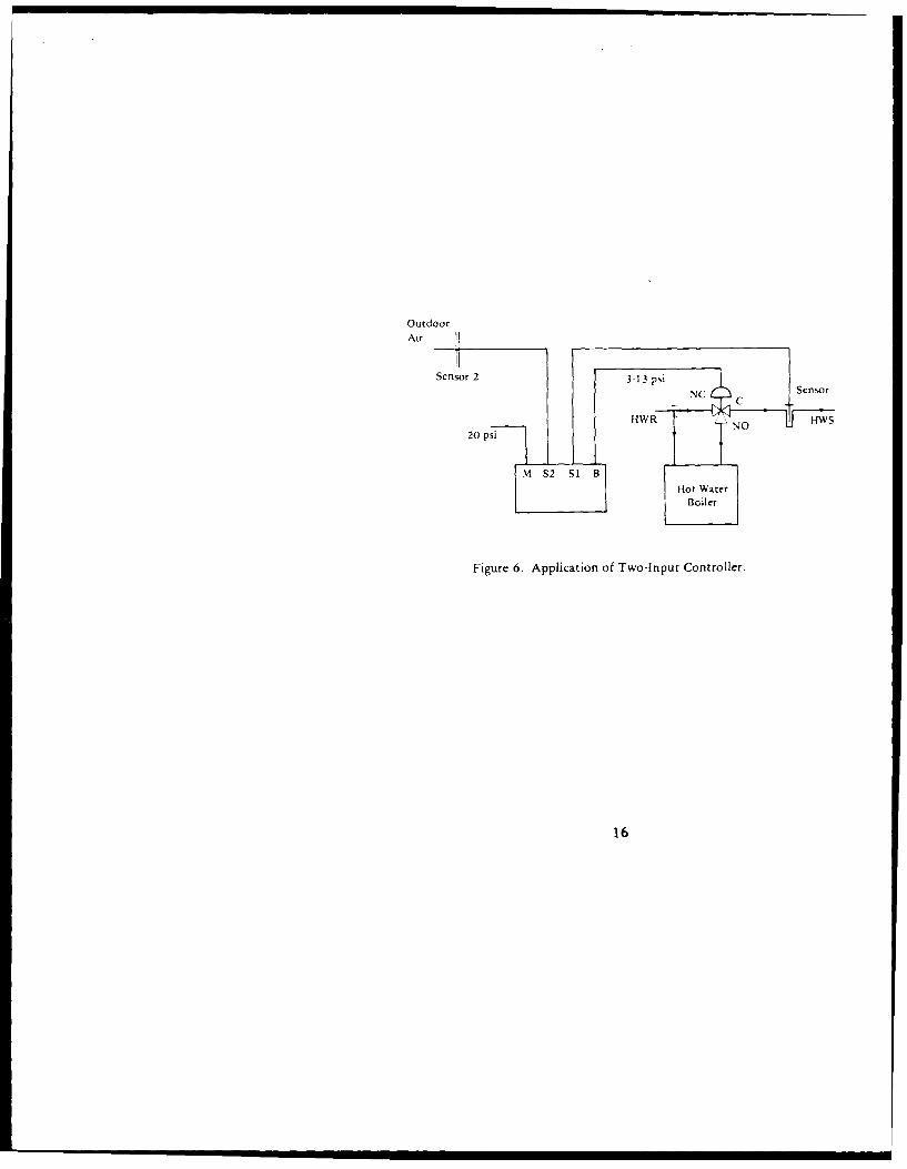
Example. A two-input pneumatic proportionalcontroller is used to reset, or change thetemperature setpoint, of a hot water supplybased on the temperature of the outdoor air asillustrated in Figure 6. Reset is employed toreduce energy consumption and short-cycling ofmechanical equipment. The reset schedule ispresented in Figure 7. This application illus-trates reverse reset action since a decrease inthe value of the reset variable (TnA) has thesame effect as raising the setpoinE on a single-input controller measuring the primary variable(T11 g). In general, direct/direct action two-inpui controllers produce reverse reset action.It is helpful to put the reset schedule informa-tion in tabular form:
14
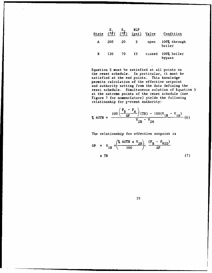
S S BLPState (O) (Ob) (psi) Valve Condition
A 200 20 3 open 100% throughboiler
B 120 70 13 closed 100% boilerbypass
Equation 5 must be satisfied at all points onthe reset schedule. In particular, it must besatisfied at the end points. This knowledgepermits calculation of the effective setpointand authority setting from the data defining thereset schedule. Simultaneous solution of Equation 5at the extreme points of the reset schedule (seeFigure 7 for nomenclature) yields the followingrelationship for p-rcent authority:
(100(P B PA.)(TR) - 100(V1B - V1A)V2B V 2A
The relationship for effective setpoint is
SP = V +% AUTH x V 2B) (PB " PHID)B 100 AP
x TR (7)
15
OutdoorAir 1
Sensor 2 3-1 3 psi Sno
CN C C
20 psi HR'N
W
I M $ $1 B ltot Water
I Boiler
Figure 6. Application of Two-Input Controller.
16
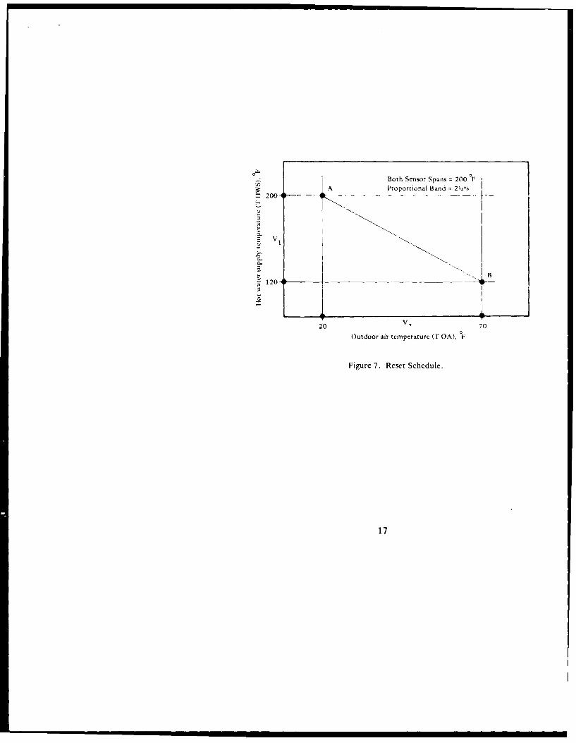
0 ,, Both Sensor Spans = 200 F
A Proportional Band = 2/2%200 -- _---_
-V 1
S120- il
20 V 70
Outdoor air temperature (T OA), F
Figure 7. Reset Schedule.
17
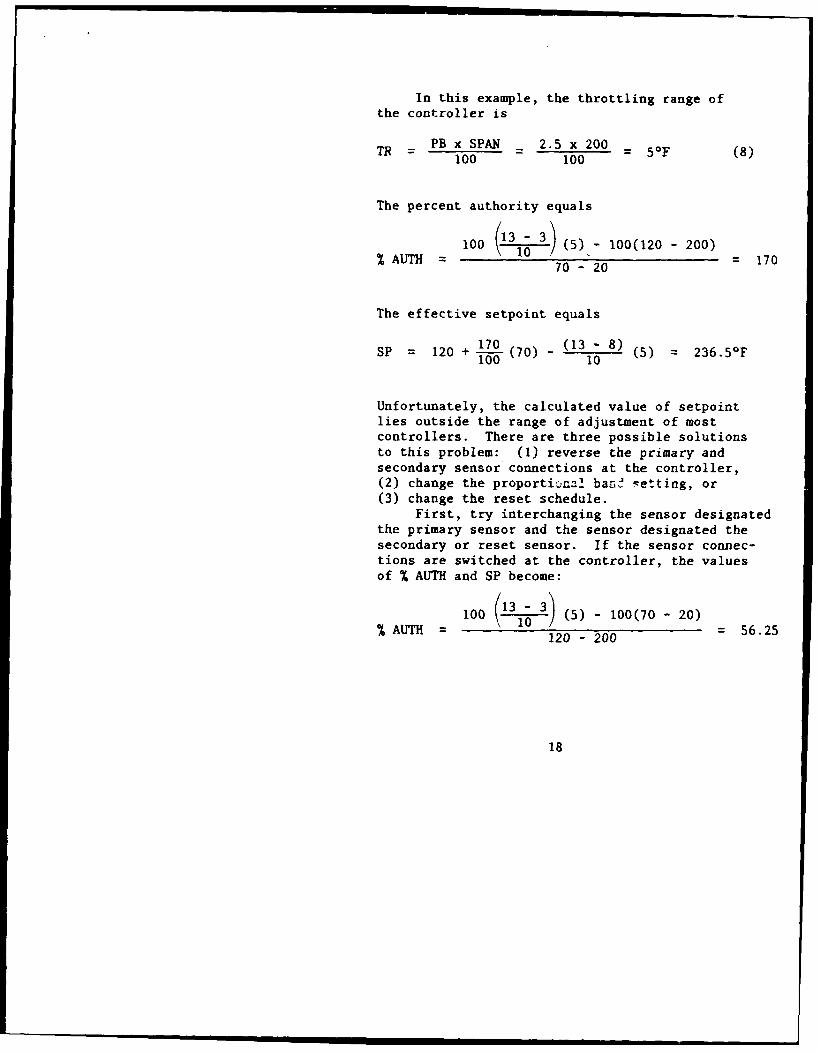
In this example, the throttling range ofthe controller is
= PB x SPAN - 2.5 x 200 = 50F (8)100 100
The percent authority equals
100 (31- 3 (5) - 100(120 - 200)% AUTH =0 )=0-,2 170
70-20
The effective setpoint equals
SP = 120 + 170(70) _ (13 - 8) (5) = 236.5°F100 10
Unfortunately, the calculated value of setpointlies outside the range of adjustment of mostcontrollers. There are three possible solutionsto this problem: (1) reverse the primary andsecondary sensor connections at the controller,(2) change the proportijna! bans ,etting, or(3) change the reset schedule.
First, try interchanging the sensor designatedthe primary sensor and the sensor designated thesecondary or reset sensor. If the sensor connec-tions are switched at the controller, the valuesof % AUTH and SP become:
AUTH -100 (13 1 3') _ 100 (70 - 20) 562% AUTH = /= 56.25120 - 200
18
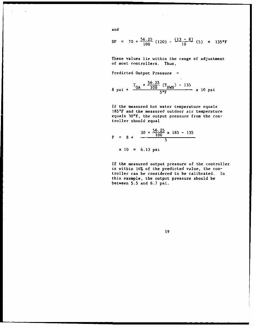
and
SP = 70 + 56.25 (120) - (13 - 8) ( = 135 0F100(10 10
These values lie within the range of adjustmentof most controllers. Thus,
Predicted Output Pressure =
T +56.25 1358Tpsi++IGA ---O- (Tiiws)-138 psi + 50F x 10 psi
If the measured hot water temperature equals185*F and the measured outdoor air temperatureequals 300F, the output pressure from the con-troller should equal
30 + 56.25 x 185 - 135100P= 8+
x 10 = 6.13 psi
If the measured output pressure of the controlleris within 10% of the predicted value, the con-troller can be considered to be calibrated. Inthis example, the output pressure should bebetween 5.5 and 6.7 psi.
19
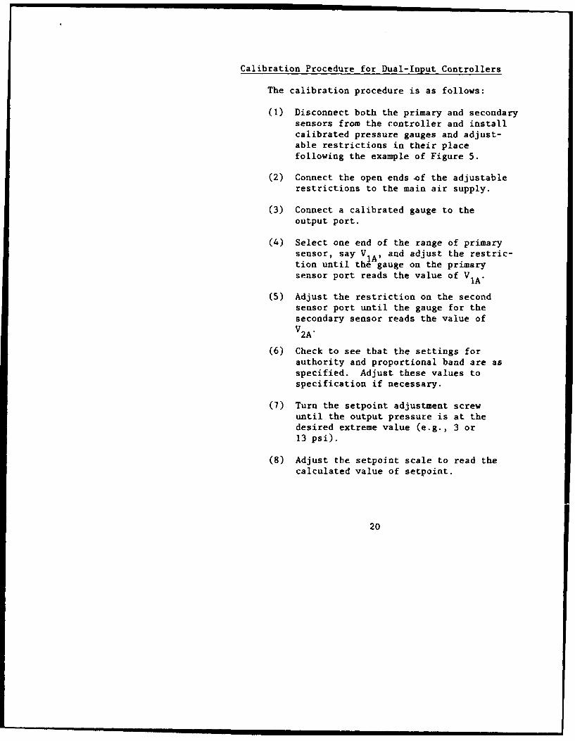
Calibration Procedure for Dual-Input Controllers
The calibration procedure is as follows:
(1) Disconnect both the primary and secondary
sensors from the controller and installcalibrated pressure gauges and adjust-able restrictions in their placefollowing the example of Figure 5.
(2) Connect the open ends of the adjustablerestrictions to the main air supply.
(3) Connect a calibrated gauge to theoutput port.
(4) Select one end of the range of primarysensor, say VI, and adjust the restric-tion until the gauge on the primarysensor port reads the value of VIA.
(5) Adjust the restriction on the second
sensor port until the gauge for thesecondary sensor reads the value ofV2A"
(6) Check to see that the settings for
authority and proportional band are asspecified. Adjust these values tospecification if necessary.
(7) Turn the setpoint adjustment screwuntil the output pressure is at thedesired extreme value (e.g., 3 or13 psi).
(8) Adjust the setpoint scale to read thecalculated value of setpoint.
20
(9) Adjust the restrictions on the sensorports so that the input gauges readthe values of V and V ̂. The outputpressure should now rea the otherextreme value (e.g., 13 or 3 psi).
(10) After the HVAC system returns toequilibrium, recheck the calibration.
Any controller that cannot be calibrated ordoes not stay in calibration, should be repairedor replaced. Controller calibration checksshould be performed at about 6-month intervals.
21