Embed Size (px)
Citation preview

71111r1r111,,40. ,C11,7
k-01)10-CRAFT LIBRARyAriosig !Mg%
HOWTO BECOMEA RADIOSERVICE MAN
How to Get Started and How to Make Money
in Radio Servicing
with
Complete Constructional and Technical Data
by Louis Martin
PUBLISHED ByI GtRNISBACK PUBLIC.ATIONs
99 HUDSON ST - NEW YORkv. -1w iw4W4416.

Atwater Kent Mfg. Co.Audiola Radio Co.Autocrat Radio Co.Belmont Radio Corp.Century Radio Products Co.Chevrolet Motor Corp.Chrysler Motor Corp.Colonial Radio Corp.Crosley Radio Corp.Delco Appliance Corp.Detrola Radio Corp.Emerson Radio & Phonograph Co.Fada Radio & Electric Corp.Ford Motor Corp.Ford -MajesticFranklin Radio Corp.
The 1935 (volume 2)
Official AUTO -RADIOSERVICE MANUAL
$250 List
11935 't'tlP . OFFICIAL
411r
',,C110 AUTO -RADIO.SERVICE MANUAL
Complete Directory -.1 All
- Automobile Radio Receivers
Over 240 Pages Printed onSpecial Thin "Bible Paper"
Over 500 Illustrations
Flexible,Looseleaf Leatherette Cover
HERE NOW-Is the second volume of theOFFICIAL AUTO -RADIO SERVICE
MANUAL-the 1935 Edition.With so large a number of new auto -radio
sets placed on the market by different manufac-turers, the 1935 OFFICIAL AUTO -RADIOSERVICE MANUAL becomes an, essential partof Service Men's equipment. Remember, thereare nearly 1,800,000 auto -radio sets in use today.
THERE IS ABSOLUTELY NO DUPLICATIONOF MATERIAL BETWEEN THE 1933 EDITION(VOLUME I) AND THE NEW 1935 EDITION(VOLUME II). THE MATERIAL IS 100% NEW.
Every radio man connected in any way witlthe booming auto -radio business needs a copy ofthe 1935 OFFICIAL AUTO -RADIO SERVICFMANUAL. It contains only auto -radio service"dope."
HERE ARE HIGHLIGHTS OF THE 1935AUTO -RADIO MANUAL
240 pages crowded with diagrams, service material and otheressential data required for proper servicing of new auto -radio receivers. Included are diagrams of sets which ap-peared during 1934, and which were not included in thesupplement to the first edition.Complete schematic diagrams, chassis layouts, voltage tabu-lations and servicing instructions are included for practicallyall sets. "Under -side- tube symbols arc also included tofacilitate the job .of servicing the sets.
Instructions are included with many sets telling how to suppress stub-born cases of ignition interference. This includes the newest "suppress-orless'' sets-and what to do when interference is encountered withthis type of set.Details on how to make installation in "turret -top'' cars are included.The different methods used by car makers and set manufacturers arelisted with the individual circuits and service information.The index contains the listing of .'sets which were published in thefirst edition, as well as the sets which appear in the new volume. Thisinformation helps the Service Man to locate the circuit and details forany receiver that has been made.The book is bound in a handy, flexible leatherette cover. To he surethe pages are sturdy, to withstand constant use, the book will he printedon a special -bible- stock. This is a very durable. but thin paper.The book printed on this paper can he easily rolled to fit into yourpocket or slipped in the service kit.
Here Is a Partial List of Sets CoveredGalvin Mfg. Corp. RCA Manuacturing Co., Inc.General Electric Co. Sears Roebuck & Co.General Motors Corp.Graham -Paige Motors Corp.Grigsby-Grunow Co.Chas. Hoodwin Co.Howard Radio Co.Hudson Motor Car Corp.International Radio Corp.Karadio Corp.P. R. Mallory & Co.Montgomery Ward & Co.National Company, Inc.Noblitt-Sparks Industries, Inc.Philco Radio & Television Corp.Pierce Airo, Inc.
Sentinel Radio Corp.Sparks-Withington Co.Stewart Radio Corp.Stewart -Warner Corp.Stromberg-Carlson Tel. Mfg. Co.Transformer Corp. of AmericaUnited American Bosch Corp.United Motors Service, Inc.U. S. Radio & Television Corp.Wells Gardner & Co.Wilcox -Gay Corp.Rudolph Wurlifzer Mfg. Co.Zenith Radio Corp.
Send remittance of $2.50 in form of check or money order for your copy of the 1935OFFICIAL AUTO,RADIO SERVICE MANUAL. Register letter if it contains ca §hor currency. THE MANUAL IS SENT TO YOU POSTAGE PREPAID.
99PR HUDSON STREETGERNSBACK PUBLICATIONS, Inc. NEW YORK. N. Y.

What Others Sayabout thisManual:
Norfolk, Va.I received the OFFI-
CIAL RADIO SERVICEMANUALS ordered asper my letmr of March1t,, 1935 in good order.
I am very well pleasedwith same as it is a veryvaluable Radio Servicedata reference and guide.
Arthur J. Freeney.
Detroit, Mich.Received your 1935
OFFICIAL RADIO SER..VICE MANUAL andcertainly is something torave about. It's great.
A. Hedke.
Stillwater, MaineI have received the
035 Manual, and I amvrry much pleased withmy investment.
Franklin J. Holmes.
Swift Current,Saskatchewan, Canada.
I beg to acknowledgenrceipt of my 1935 issueof the OFFICIAL RADIOSERVICE MANUAL.
Your Manual is fine,and would not be withoat any of them. TheManuals may he improvedGar Canadian use.
A. M. Ford.
--for the realservicing "dope"
you can't find abetter book!
1935 Manualof profitablepublished before.
Contents of the 1935 Manual
NO other radio book is comparableto the 1935 OFFICIAL
RADIO SERVICE MANUAL. Incontents, in style of printing, ingrade of paper, in illustrations, therehas never been published such a coin,prehensive volume.
The 1935 Manual contains over athousand pages-yet it is only 11/4inches thick because it is printed ona special Bible stock which is an ex-ceptionally good stock, yet one of thethinnest and most durable papers.This 1935 Manual is the most au,thentic and elaborate service guideever used in the radio industryService Men and dealers who use this
are astonished by finding in it such a wealthservice information which has never been
Over 1,001) pages full of diagrams and essential informa-tion of manufactured receivers-only data of real use inservicing is included. This new Manual is really portablesince it will be extremely thin and light as well. VolumeV continues where the preceding manual left off. Manycircuits of old sets are included. Service Men knowevery set has certain weak points which are really thecause of trouble. Wherever the information could beobtained, these weaknesses with their cures are printedright with the circuits. This is an entirely new and valu-able addition to the Manual. All the latest receivers areincluded-all-wave sets, short-wave sets, auto -radio sets,midget and cigar -box sets, etc., as well as P.A. amplifier;and ' equipment, and commercial servicing instruments. The cumulative index is even more complete than be-fore: including cross-reference to sets sold under differentnames and type numbers. Volume V includes resistancedata; socket layout; I.F. data; and voltage data. Tubedata on latest tubes. Free question and answer service
;Is included in our last three manuals.
OVER 1,000 PAGESOver 3,000 Illustrations
Flexible. I.00seleaf Leatherette CoversSize 9x12 Yet only 11/4" thick
Send remittance of $7.00 in forth of check or mon,ey order for your copy ofthe 1935 OFFICIAL RADIO SERVICE MANUAL. Register letter if it con-tains cash or currency. THE MANUAL IS SENT TO You POSTAGE PREPAID.
GERNSBACK PUBLICATIONS, Inc.99PR HUDSON STREET NEW YORK, N. Y.

IIIctrsryFood PreservationTheory and Fundamental LawsMethods of RefrigerationRefrigerants, Lubricants and
BrinesHandling, Testing and Storage
of RefrigerantsCompression Systems of
RefrigerationLiquid Throttle Devices and
%/JivesRefrigeration SystemsF tric Control Devicesr rr westors, Types. Seals
Valrot Capacities, Service
OFFICIAL
REFRIGERATION
SERVICE MANUAL
VOLUME 2
THIS IS THE ONLY COMPLETE
REFRIGERATION SERVICE
MANUAL EVER PUBLISHED -
Entirely Neu, Materialfrom (2ove1' to Coz.er!
$5.00 NET
VOI '1'\\
01' TIIF Official REFRIGERATIONOVER 352 PAGES SERVICE MANUAL
)\1:.R 300 1)1 \GR \1s Thi. Manual for, ri l'IttittlOOtOtlird Rtlittikillt.ilt tothe prey. OVEICI AI. REFRIGERATION SERVICE
CC
ANI' AI. %'oltime Ii data in the 1935ClittiPlete l)tita lime vtitircly new
The la kill Al REERIGERATION SERVICE. MAN -/qt..1 1.(ifiseleaf lt(titler LIAll. wan the sir r r..rrat ior :' r. slanunl....r
published- -and n t 1.. W ht -t11wi that they both form ri .,,pr I,,n
of information on this rapidly Vi,., T v r,Iniv,rriroi.induntry.
Detailed infornintion on perviring outline.. of theoryand methods of operation; in.trurtion. for the hand-ling of ref ri 'fern n t s chnrieing nystemn : diaensinctroubles : trouble charte electrical : rharues
oil anti refricarant in ilitTerrnt models advice onthe selection of
e placement and terniniratore re-f:Mired by foods ; valve saltine- isimpre.sor vt,11,trfie-lion, fault.. 0, erhaoltior . entimatime roil and notohineloads: are eiirointiased in this 110,, 1.1.11101, ..t ref rie.ration tettl
t,i+ ,atitiOn ift printed on a Special1..11. hie h is extremely
yet Iltiral.1.lit., :ea Pap,' nirekr,
oh.. .. It..., or, ill-, ,1 nor, 11r,.
I i st of (..ontents in the cerond Volume of theNMI la Refricontion Service Manual"
Servicing Erpansion ValveEvaporators and Cooling Units SystemsService Tools, Equipment and Servicing Thermostatic Valve
Tool Manipulation S WarnsCommercial Unit Specifications Servicing Restrictor and
and Service Capillary Tube SystemsHousehold Unit Specifications Charging Systems ,e;rn
and Service RefrigerintServicing Refrigeration Electrical Service Motors,
Apparatus FJSOI. HcolupsServicing Low Side Float Service Kinks
Valve Systems Estimating Refrigeration Loads,Servicing HIgli Side Float Coil and Machine Sites
Valve Systems Miscellaneous Data,,. r.c, no rr, o.f ,r I111,10V o.rder for yioir of the
t)EE1171 I. REF- M L Al. Ho, II..vi.rcr.!'.r If 'rot. THF. M.ANDAI. IS SENT ro YorPOSTAGE PREPAID.
99PR HUDSON STRFF1GERNSBACK PUBLICATIONS, Inc. NFW l'012 K. N. Y

4
8
CHAPTER 1
The Small, Independent Service ManAMAN enters the radio service bus-
iness because he believes it to bethe most likable and most profitablebusiness that he is capable ofrunning. In this chapter we will dealwith the man who has not sufficientmoney available to open an impres-sive store, and who desires pointers onhow a small business is to be run, theleast amount of apparatus necessary,and the probable income to be secured.
In the first place, a man who has nocapital will, in all probability, use hishome as the place to conduct the bus-iness. This is not detrimental becausein the radio service business, nearly allcontacts are made either by telephone ormail-the customer never entering theplace of business.
Apparatus RequiredThe next question that arises is that
of test equipment. Of course, the moretest equipment at hand, the better theservice that can be rendered, althoughthere is a minimum amount necessary.For instance, every shop should havean Anal zer. This need not be expen-sive nor e a (mate, but merely sufficientto obtain all current and voltage read-ings. The instrument described in thisbook may be used until business war-rants something more elaborate.
The R.F. (radio frequency) oscillatoris the next piece of equipmentshould be added. In another chap-ter in this book there is described anextremely inexpensive oscillator-infact, it may easily be built with very
/ few parts usually found around theV shop; even if parts must be purchased,
the total cost would not exceed aboutthree dollars; in many cases it may bebuilt for much less. The intermediatefrequency and audio -frequency oscilla-tors may also be built, although theyare not absolutely essential, and it iswell for the small independent ServiceMan to defer their construction untilhe has built up a reasonable amount ofbusiness. Thus far, the analyzer is theonly essential piece of test equipment
3
that should be had before opening up aradio service business.
Hand tools are, of course, a necessaryaddition to any service organization.An elaborate collection is not necessary,but for the man who is in doubt as tothose which are desired, the followinglist is suggested:
One neutralizing adapter (4 p19.11.g,UR);
One neutralizing adantSr (5 prong,UY);
One small hand drill with assorteddrills; several small files;
One hammer;One paii:_bigh_cestistance telephon,
receivers;One electrician's knife;One pair diagonal cutting pliers;One pair long nose pliers;One pair 6 -inch side cutting pliers;One non-metallic screw driver;One large screw driver;One small screw driver;One electric soldering iron; rosin -
core solder;One roll of friction tape;Assortment of nuts, bolts, screws,
eto-.;/One roll solid No. 18 push -back wire;
Two non-metallic socket wrenches;One set small open-end wrenches.The above are essential to clean-cut
servicing although many Service Menhave their own ideas on just what toolis necessary for a certain job. The fol-lowing list is also suggested as addi-tional material which should be carriedor kept in the shop, depending upon lo-cal conditions.
One small bottle wood alcohol;One bottle household ammonia;One small piece of cheese cloth;One small bottle vaseline;One small bottle furniture polish;One dentist's hand mirror;One small hydrometer in carrying
case;One small flashlight, fountain pen
type;Seven small fixed condensers-

4 HOW TO BECOME A RADIO SERVICE MAN
.0001, .001, .006 .00025, .01, 5J-0,_ 2.0mfa.,
Eight grid leaks, varying in sizef om .1 to 10 megs.;
Two glass insulators, several "Nail -it" knobs;
Fie carbon resistors,_ 500 700, 800,1000, an o -'s;
Six variable wire -wound resistors,202Q,59.(& 10,99.9,_21Q9(),__§9, coo, and10.0000 ohms;
One aerial wire;One roll lead-in wire;One small blow torch.Many men contemplating entering
the service field, no doubt, have hadmechanical experience before, so thatthe above list of material will be veryfamiliar. In general, it will be foundthat only a few additions are necessaryto the above list in order to have acomplete set of "radio" tools.
Getting Business
The small man with only about fiftydollars available has a little problembefore him when it comes to gettingbusiness. Ordinary means such asnewspaper advertising cannot be usedfor very obvious reasons. It is the pur-pose of this section to suggest waysand means of advertising (which is theonly means one can get business) sothat the greatest number of desirablepeople may be reached for the least ex-penditure of money.
The very first thing that should bedone is to install a telephone. The ini-
i tial deposit is small compared with thef results secured by its use. While ad-
ditional rules and regulations may belaid down, the reader may doubt thevalidity of some of the methods sug-gested. For this reason the author hasdecided to quote from some actual ar-ticles that have been published by thatexcellent Service Man's magazine,Radio -Craft. These letters and arti-cles are reproduced with their kind per-mission.
The following has been abstractedfrom an article which appeared recent-ly in Radio -Craft, entitled "The Bus-iness End of Radio Servicing," byGeorge K. Graham.
It should be noticed that the methodsused by Mr. Graham are absolutely ap-plicable to the small Service Man; no
large outlay of money is necessary, andthe results are certainly satisfying.
"The writer has met Service Men ofall kinds and types; some are success-ful, some are not. A peculiarity he hasfloted is that the successful ones usual -y know the least about technical radio;
while those who are more technicallyinclined do not seem to get fair pricesfor their work. The reason may bethat the over -technical radio man is soengrossed with radio itself that heforgets he is in the servicing businessprimarily to make money.
Go After Business"Promotion work can be successfully
applied to radio service work and willgive handsome returns. Your pros-pects are the people who bought batterysets years ago, and who are constantlypatching them up to keep them go-ing, those who bought the earlier elec-tric sets, and those who have had their
inewer machines long enough to havepassed the guarantee period. A largepercentage of set owners have pur-chased their radio receivers from adealer but will, through some misun-derstanding (usually over credits, etc.),make a practice of having them repair-ed by some outside man. You may aswell be the man to do this work forthem.
"Right now, in your own town, someone is wondering whom to call for radioservice. Make it your business toreach these people. True, not everyone you come in contact with needsservice right now; but you know thattubes, condensers, resistors and trans-formers, etc., have a definite life. Setowners will need service sometime.Make them acquainted with your bus-iness; not after they have had servicedone elsewhere, but before, in time foryou to get the job. Get to these peo-ple first, tell them your story, leaveyour name with them-then when theydo need service they will think of you.Your business will be in direct propor-tion to the number of contacts you havepreviously made.
"A good plan to follow is a combin-ation of telephone canvassing and di-rect -mail advertising. You can call atleast twenty-five people a day and offerthem a free radio inspection. Yourmethod of approach may be somewhatlike this:

HOW TO BECOME A
'Hello Mr. Brown this is Mr.Jones the radio man. I have juststarted in the radio service bus-iness and in order to become ac-quainted with the people in townI am offering a free radio inspec-tion. I will be glad to come toyour home and inspect your radio,test the tubes, and check the an-tenna and ground installation.How long have you had yourradio, Mr. Brown?
'You say your machine is a yearand a half old? By the way, Mr.Brown, have you had the tubestested lately? You know thatsometimes you can get better re-ception if you rearrange the tubesin your set. I will be glad tostop up and test the tubes foryou and try to get the best recep-tion possible. I am doing thisjust as a sample of my work; sothat when you do need service youknow where to call.'
"If he agrees to allow you to inspecthis set, make an appointment andKEEP it.
If not, continue, and say:'Well, Mr. Brown, I am glad to hear
that your radio is working satisfactor-ily and, so that you will know where tocall, I am going to mail you my tele-phone number and address.' Exper-ience has shown that twenty-five tele-phone calls will net, on an average,eight inspections; and, of these eightcustomers there should be no difficul-ty in selling four of them at least sometubes or other accessories.
Keep After It"Don't be afraid to do a little extra
work. It won't be necessary after yourbusiness has come to the point whereyou have enough daily calls to keep youbusy. But, until then, keep right atyour promotional work.
"The next day after your phone con-versation mail your prospect a card orletter telling him your story all over,giving your telephone number. Followthis up with a second letter, impressinghim with the desirability of having hisradio checked before it really givestrouble. Sell him the idea of havinghis set put in good shape before trou-ble really develops and denies him hisradio for a few days. Stress the idea
RADIO SERVICE MAN S
that `An ounce of prevention is wortha pound of cure.'
"While these letters will not giveimmediate results, they are doing theirbit to sell your customer the idea ofcalling you the next time he needs ser-vice. After the second letter, twoweeks later, mail your customer a postcard, giving him a reminder that youare still waiting to serve him. Contin-ue this card system at least once amonth. Call the people on the phoneregularly until they get to know you.Remember, too, that before you enter-ed the business they were having theirradio taken care of by someone else,
MRS. MARY SMITH,Baldwin Place,
Oceanside, L. I.Dear Mrs. Smith:
A Stradivarius violin worth twenty thou-sand dollars is musically valueless withouta little ten -cent chunk of rosin to rub onthe strings. A Rolls-Royce costing sixteenthousand dollars won't budge an inch with-out six little spark plugs costing seventy-five cents a piece.
So you see, when you stop to think aboutit, the little things are tremendously im-portant. Which brings us to our subject:Is your Radio working satisfactorily-or isit just working? Why be satisfied withanything short of perfect Radio receptionwhen it is so easy to get the best out ofyour Radio?
Just call Rockville Centre 701. One ofour highly skilled Radio experts will callat your home and inspect your Radio, testthe tubes, check the installation, all FREEOF CHARGE. Why not take advantage ofthis offer t You owe it to yourself andyour family to see that your Radio is giv-ing the satisfaction it is designed to give.Why let some minor accessory cheat you outof this real Radio enjoyments Don't delay.Take advantage of this offer. We awaityour call.
Yours for Radio enjoyment,GRAHAM BROS.
A brief, pithy service sake letterit is your job to sell them the idea ofcalling you.
"Do not make it a practice to useprice as the bait, use reliability andpromptness as your main selling points.Ask your old customers for the namesof their friends and follow these namesup in the same manner except that youcan mention the friends' name and inthat way make the conversation morepersonal.
"Your follow-up letters and cards canbe cheaply mimeographed and, if yousend out twenty-five pieces of mail aday, you will be able to keep at it. This

HOW TO BECOME A RADIO SERVICE MAN
system is much better than mailing abroadside of, say, a thousand piecesof mail once, and then forgetting aboutit. Make this follow-up system a re-ligion.
"After you have serviced a set forone of your customers send them athank -you letter, emphasizing the factthat you are interested in their well- /
being from a Radio standpoint. Makethem feel that you are interested inthem, not only in their money. Makeyour contacts serve you by showing thepeople that you are conscientious.
Dear Mr. Jones:Is your radio working satisfactorily-or
is it just working -1Perhaps you have been using your radio
for the past six months or so without havingit ci.ecked. It may be that just a tube orsome minor accessory is standing betweenyou and complete radio enjoyment.
No matter what radio receiving set youown-no matter if it is be electrically orbattery operated-no matter if it be old ornew, your receiver does require attention.Perhaps we can be of service to you; andwe will appreciate your consideration.
"Those Serve Best who serve with suf-ficient knowledge and sincerity of purpose."We are radio service specialists with suf-ficient knowledge and sincerity of purposeto insure you of complete radio satisfaction.We deal in radio facts instead of radiopromises and hopes. We are capable radioengineers and our radio knowledge is atyour disposal.
Let us look out for your radio interests.Call Rockville Center 701. Our inspectionand advice costs you nothing. Why notcall now and have your radio set inspectedbefore trouble develops?
At your service,GRAHAM BROS.
An introductory letter, such as Mr. Grahamusrd in his "get -acquainted" campaign.
How to Sell New Tubes"A very good method that has been
used with considerable success in fol-lowing up these free inspection calls-and regular service calls for that mat-ter-is to have your service kit, tools,etc., in a suitcase large enough to holdthe test kit, tools and at least a set oftubes for the particular type of receiv-er you are servicing at the time. Whenyou are in the customer's home, askthem how long they have had thel'rmachine, what previous trouble theyhave had, etc.; this will give you ageneral idea of just what may bewrong.
"The first thing to do is to examinethe machine in its present condition.
Proceed to take the customer's tubesout of the set, and place them to oneside; then insert the full new set oftubes, explaining to your customer thatyou always check the set with your owntubes; as this save time and troublein case a tube should burn out duringthe testing. After you have tested themachine and rectified any difficultiesthat may have been present, take yourtube tester and test the customer'stubes, carefully noting any that maybe weak.
"Now, with your own tubes in theset, tune in one of the weaker stations;and then remove your tubes, one byone, replacing them with the customer'stubes. If he has any weak tubes, hewill immediately see that there is adifference in results with good tubes inthe set; and the task of selling him newones will be much lighter. Rememberthat the manufacturer designed the setto work with perfect tubes and it isyour duty to see that the set has justthat; your customer will thank youafter he sees the difference in results.As ninety percent of the radio publichave been sold on the idea that tubesare the most important part of aradio, you can capitalize the idea andmake it pay you handsome dividends.
"The practice of having the tubeswith you will save you many a sale;because sometimes, while you are run-ning back to the store, the customergets a chance to change his mind, andmay decide to run the set just as it is.Get the job done as quickly as possibleand cash in on the interest the customerhas in his set at the moment. Lateron, something else will captivate his at-tention; remember the old adage ofchain and department stores-"Theynever come back.' Very few of thecustomers, who say they will call whenthey can afford the tubes, will call youback. But, if you are tactful and per-sistent, you can sell them the tubeswhile you are right on the job.
Mistakes to Avoid"Of course, it goes without saying
that you will only ruin your business ifyou attempt to force tubes and acces-sories on people who do not actuallyneed them. But, if a man has weaktubes in his machine and is cheatinghimself out of real radio enjoyment,it is your duty to him to show him and

HOW TO BECOME A
convince him that his radio can begreatly improved. This idea does notinvolve tubes alone, but covers anyother item that the customer may needto make his reception perfect. Someowners do not know just what theirreceivers can do; they will go alongwith only halfway results. Show thesepeople just what the possibilities are,and you will make a success of the bus-iness. Their friends will notice the dif-ference, and this will bring you muchgreater returns in new business.
"In servicing receivers that havesome major defect, such as a burnt -outtransformer, it is good general prac-tice never to spend more than thirty
Dear Radio Owner:We are reminded of a story told about the
late P. T. Barnum, the famous circus mag-nate and practical joker. It seems that,while he was giving one of his shows inthe rural sections of the country, Mr.Barnum decided to add a "FREE" attrac-tion to his already famous circus. Thisattraction was a highly decorated doorwaymarked, "FREE EXIT." When our coun-try friend entered the doorway and passedthrough, he found himself outside the groundsand was faced with the necessity of payinganother admission to re-enter the groundsto see the show.
FREE RADIO SERVICE Is usually worthjust what is asked for It-nothing. Manyof the residents of this and other suburbanlocalities purchase their Radios from largechain stores located in nearby cities. Theselarge Radio outlets advertise FREE SER-VICE.
Out of fairness to the large stores, wemust remember that the largest portion oftheir customers are located in the big citiesnear to the stores. To these customers thebig stores do give prompt, efficient service;but what happens to the service calls fromthe suburban towns?
Put yourself in the place of one of thesebig stores. Close at hand you have 90 per-cent. of your service work; the other 10percent is spread throughout a circle ahundred miles in diameter. To do one serv-ice call in the suburbs takes as much timeas do ten calls nearby. What is thenatural consequence of this condition? Thesuburbanite has to wait until the service de-partment has enough calls out his way towarrant sending a man to his locality.
To YOU, a suburbanite, this means wait-ing days-sometimes weeks, for service, andthe most expensive Radio is useless unlessit is giving entertainment-that's what youbought it for. It is not necessary to waitfor service.
Yours for complete Radio enjoyment,GRAHAM BROS.
A sales letter urging the value of promptservice when it is wanted.
RADIO SERVICE MAN
'Dear Patron:We wish to thank you for having given
us an opportunity to be of service to you.We realize that a successful business canonly be built on good will. Our interestin your Radio does not cease with the merecollection of the service charges. It i ourearnest desire to have each machine servicedby us, act as an advertisement of our busi-ness. Now that your Radio has been placedin good working order, it will be to youradvantage to keep it in this condition. Youcan easily and inexpensively do this by tak-ing advantage of our monthly inspection.
This inspection service consists of a thor-ough checking of your Radio and all theaccessories once a month. This proceduregreatly reduces the repair bills that are in-evitable when a Radio is neglected. Thetotal yearly cost of this inspection service isless than it would cost to replace one partin your Radio. It has been our experiencethat most people do not give any attentionto their Radio unless it has actually stoppedworking. Many times during the course ofour regular inspection we can detect troubleand prevent it from doing serious damageto your machine. If it were only for thesake of having your Radio alwys in opera-tion when needed, it would be worth theprice asked for this inspection.
May we offer you this service at theamazingly low price of $1.50 per call! Thiswill include checking the tubes and re-activating any that may be weak, checkingthe aerial installation, speaker, power unit,or other accessories, testing the speaker fortone, and making any minor adjustmentsthat may be necessary. If you wish to takeadvantage of this offer, return the enclosedcard and we will enter your name on ourinspection list.
May we again thank you for your patron-age and solicit your continued good will,and that of your friends?
Yours for Radio Satisfaction,GRAHAM BROS.
A "breadandbutter" letter sent after makinga first call.
minutes' time on the machine in thecustomer's home. They have an ideathat you must find the trouble immedi-ately. The average customer dislikesvery much to have his radio torn apartin front of him. Take the set to theshop where you can work in peace, anddo a much better job.
"A hard and fast rule, never to bebroken is: never, under any circum-stances, take the customer's tubes withyou when you take a machine to theshop for repairs. This will save youmany an unpleasant scene when youhave found that there are defectivetubes in addition to the trouble youhave just repaired. If the customer'stubes have not left his home, there can

8 HOW TO BECOME A
be no question as to whether or notthey are his tubes. After you returna set from the shop you can proceed asoutlined above, and often make an ad-ditional tube sale."
No one will dispute the fact that Mr.raham is not only a radio Servicean, but also a business man. While itay not be advisable, due to lack of
sufficient financing, to mail twenty-fiveletters a day, nevertheless the sameidea may be followed on a much smallerscale. The idea of the manner in whichto obtain business, however, is there.Mr. J. P. Kennedy offers some inter-esting methods of obtaining business.He not only states the methods thatbrought in trade, but also discussessome which proved to be failures. Someof the circulars sent by Mr. Kennedyare included as a suggestion.
(Published in a recent issue of Radio-Craf t.)"The first problem requiring thoughtwas to reach the greatest number ofpeople with the message, not only that
a radio Service Man was available, butthat they needed this particular ServiceMan right now. Under the mistakenidea that low prices would get the re-sults, five hundred government postcards were printed and sent out offeringservice at one-third the regular rate of$1.50 for a limited time. The idea prac-tically failed. The "something -for-nothing" people were the only onesthat called; and they wanted more fortheir fifty cents than two ordinary callswould entail.
"The next idea had more merit andcertainly more profitable results. Theradio page of our leading local paperwas such an uninteresting sheet thatmost of the radio advertisers requestedother locations to make their copy ef-fective. 'Let's write something of in-terest for that page, something thatwill consistently attract readers who,in turn, will see the ads.' That ideajappealed to the editor. He offered torun free with my name at the head, a
daily column on radio, if I would supplythe copy."A question and answer column seem-ed the logical medium and, as enough
questions would. not come in to supplythe daily assignment, it would be neces-sary to write not only the answers butthe questions. To make them appeargenuine, fictitious initials could be sign-
RADIO SERVICE MAN
ed. It took six hours of typing to pre-pare the first two weeks' copy. Theidea clicked instantly. Actual fan mailbegan to come in with real questions.People began to ask, 'Who is this/chap, Kennedy?' Sensing that query,I ran ads, tieing in with the column,with my picture and suitable copy. Thecalls for service were increasing daily.
A Direct -Mail Campaign"There are a large number ofwealthy people in this city (SouthBend, Indiana). Their trade and goodwill was the next objective. Torturedwith staid mimeographed advertising,that went in the waste basket, thesepeople are the hardest to reach. Per-sonal calls are impossible with count-less butlers, maids and private secre-taries to block reaching their super-iors."Personal letters seemed the onlysolution. They must be sent in plainenvelopes on plain white paper, with
J no letter head that would betray theircommercial aspect. They must havehuman interest, discreet flattery, thepersonal touch, and a dynamic com-pact message - high-pressure stuff.Everyone who has lived in a given com-munity, for a few years, knows at leastthe big civic and industrial characters.If not, almost any old citizen can sup-ply not only the names but countlessstories and incidents about these prom-inent people. There is your material.A typical letter is reproduced here.
Use of Good Printing"An important part of a Service
Man's equipment is a good businesscard. Taking advantage of the meth-ods used by politicians to get their per-sonality across to the voters, I resortedto a business card bearing my own pic-ture and a minimum of printed mater-ial. The more simple and unique thecard is, the more dignified and effectiveit is with the most desirable class oftrade.
"Study the business cards of success-ful firms and men. Ask yourself whatappealed to you in a particular card;take that idea and use it in your owncard. Color, discreetly used, distin-guishes a card. I use two straight bluelines (despite the extra cost of a see-ond run by the printer) to get awayfrom the conventional black, yet em-ploy a cool color that will not distract

HOW TO BECOME A RADIO SERVICE MAN 9
Your Wifesad Family DeserveLightning Protection
Lightning ArrestorsInstalled
This Week Only
$1.00
.1. P.a
The "ad- st the left was less successful"human
the eye of the reader from the printedmatter. I consider this card on a parwith any other form of advertising I
7co ld give a prospective customer.
"To supplement the business card, apersonal letter of appreciation goes toevery new acquaintance I make. Itapparently does no harm to flatter newfriends; they remember you long afteryou have forgotten them.
"Studying the successful method ofselling employed by allied industries, Itook the idea of the persistent FullerBrush salesmen and reworked it tosell service. The addresses of houseshaving an aerial could be secured bymerely walking down the street. Thecity directory supplied the names ofthe occupants of these homes. I select-ed ten a day and mailed a governmentpostcard bearing my picture and amessage.
"This announcement has been gain-ing entrance to 70% of the homes it issent to. True, it costs time and energyto make these free calls; but half ofthose called on need new tubes, light-ning arrestors, tone controls or actualrepairs and-believe it or not-theybuy them and average you $1.50 to$2.00 per call. The days when youcould sit around the shop, and wait forthe calls to come in, have passed. Thereis plenty of business if you go afterit.
yegE
than that in the center, which introducesinterest."
"I tried an interesting experimentin selling lightning arrestors. Theweather reports were watched careful-ly for an announcement of an approach-ing thunder storm; and an ad was thenrun with a scare headline in italics.'Not a single call resulted from the ad!
"The copy was changed, a little per-sonal family interest was injected; andnot only was a stock of slow -movinglightning arrestors sold, but I obtainedthe opportunity to sell tubes and otheraccessories on the same call.
"The natural question other ServiceMen will ask, when they finish readingthis article, is: 'How much is Kennedymaking with all these advertisingstunts? How big is the city he's in?'
"The business will average $10.00 aday profit or return for labor while youwork. Being human, I take a day offoccasionally for a little golf; devotea few evenings a month to social af-fairs; oversleep some mornings; at-tend the weekly meetings of the Ki-wanis Club and take part in any civicaffairs that call for volunteers. (That'sreal publicity plus the satisfaction ofdoing a good turn.) South Bend is anindustrial city of slightly over 100,000population, with a fine friendly groupof people and with the well-known Uni-versity of Notre Dame at its northernboundary.
"The leading radio concerns have dis-

10 HOW TO BECOME A RADIO SERVICE MAN
Profit by ExperienceOF 2,900 OTHERS, CALL
J.P. Kennedy'sRadio Service
Ph. 3-2414. 118 W. LaSalle'
OUR COMPLETE KNOWLEDGEOF RADIO MEANS MINIMUM
COST OF REPAIR.
J. P. KENNEDY'SRadio Service
Ph. 3-2414 418 W. LaSalle
$10.00 FREEIt We Can't Repair Your
Radio SetJ. P. KENNEOY'SRADIO SERVICE
Ph. 3-0414 413 W. LaSalle
TheItST31
riStiFlii47e0f7/1:17;:re
;.14f; :AdpeittZ,efegtfce)4T
Ca
7k4bee
74,;v7c:/',1;Z:4:Z..
e3 rn "O.
tWith Your Radio? tahe Inns,
theyWhat's Wrong
J. P. KENNEDY'S j'aa4vell:
RADIO SERVICEPh. 3-2414 418 W. LaSalle
A combination of publicity and advertising with small space-"bullets"-frequentlyrepeated. Larger newspaper advertisements are shown below at the left.
tributors located here who supply allthe standard merchandise needed, with-out delaying you with shipping and bur-dening you with express bills. A mini-mum stock can be carried, because ofthe ease of securing additional supplies.
"Other, less -aggressive Service Menare going broke here; so, unless you canbring in new and more effective ideasfor selling service, stay in your ownhome town.
"One ten -by -ten room in my homecontains my desk, phone, service bench,and shelves for spare parts and sup-plies. No sets are brought in that canbe repaired in less than an hour in theowner's home. All my equipment ishand -made. Careful workmanship andtechnical accuracy make my instru-ments as important in the eyes of my \customers as their more expensiveready-made counterparts. Besides, af-ter designing and building an instru-ment, I know how to use it."
Of particular interest to readers ofthis book is the final paragraph of Mr.Kennedy. Note that a ten -by -ten roomin his own home is used for the shop.
While many of the methods describedby Mr. Kennedy duplicate those usedby other independent Service Men, thefact remains that those methods pro-duce results, and it is results thatcount.
Besides the methods outlined above,there are many other ideas that maybe incorporated in the service businessin order to stimulate business. Repro -
418 West LaSalle Avenue,South Bend, IndianaMarch 17, 1932.
Mr. John Riley,605 E. Howard Street,South Bend, Indiana.Dear Mr. Riley:
Have you ever had who soldyou merchandise or service take a personalinterest in your satisfaction after they se-cured your money?
A few years ago, I had the pleasure ofrepairing your Bremer -Tully radio. Thegracious manner in which I was treated byboth yourself and your charming wife lefta pleasing memory. The air of culture andrefinement that pervaded your home inspiredme to exert my best efforts and utmost skillin repairing your radio.
Not hearing from you since, I presumeyour set has been working satisfactorily,but really it should be carefully gone overat least once a year. Tubes don't last for-ever. Improvements are available, such asstatic modifiers, better known as tone con-trols, new quick heating tubes and moreefficient lightning arresters.
I am interested in your satisfaction. With-out knowing of these improvements, youmight be talked into buying a new set, whileyour present set can be brought up to dateat a fraction of the cost of a new machine.I want your friendship and the good willof your friends. This can only be obtainedby serving your interests to the best of myability. In other words, I want your radioservice business. May I have it!
(Signed) J. P. KENNEDY,J. P. Kennedy's Radio Service.
Phone 3-2414
One of Mr. Kennedy's diplomatic letters. Alittle blarney, and then a business touch.
duced below are a few well worth-while ideas that have been suggested

HOW TO BECOME A RADIO SERVICE MAN 11
in a number of editorials of Radio-Craft by Mr. Hugo Gernsback. Itwould be well for the Service Man tofollow the suggestions offered.
"Under present economic conditions,the Service Man and the radio replace-ment industry are rendering a big ser-vice to the country; because it has beenfrequently observed that the owner ofa radio set (which cannot be repaired)will go without a radio rather thanbuy a brand new one, even though hecan trade in the old set. We believeit is far better that an old set shouldbe reconditioned and put into shape,so that the set owner is satisfied forthe time being, than that he shouldlearn to go without a radio and, event-ually, be lost to the entire radio trade.This situation is not so impossible assome might think, for it has happenedtoo often with many disgusted setowners; and it is about time for theradio industry to wake up to this con-dition.
"A conservative estimate, from relia-ble sources, places the number of bat-tery -operated receivers still in use, inthis country, considerably over 5,000,-000. While practically all of them aretoday hopelessly out of the running(when we compare them with the pre-sent-day A.C. models) many still givesatisfactory, even excellent reproduc-tion; although they are a nuisance totheir owners, as far as the battery endis concerned.
Of the 5,000,000 battery sets, it issafe to say that considerably over 70percent are in homes which are wiredfor alternating current; and a small
percentage of other homes are suppliedwith direct current . . .
"There are on the market, today,any number of low-priced power packswhich can be bought cheaper now thanat any time during the past and are,without a question of a doubt, muchcheaper right now than they will everbe again. The reason is that very fewnew power packs are now built; whilethose on the market are, in many in-stances, really distress merchandise. Ofcourse, there are some new packs man-ufactured (to which we, personally,would give the preference if we had todo the job); but the drawback of these,at the present time, is that they runinto quite a sum of money and, exceptwhere the owner of a battery -operatedset has quite an expensive model, fromwhich he does not wish to part, it willas a rule be difficult to make a saleof an installation incorporating a new-ly -manufactured power pack.
"The wide-awake radio man, whowishes to cash in on the situation out-lined above, should find out how manybattery -operated sets there are in hiscommunity, and how many of them arein homes where electric current exists.This should not be difficult to find out;and even a house -to -house canvass dur-ing the dull season might bring in ahandsome harvest.
"In the city, in apartment houses theeasiest way to get information is fromthe janitor or superintendent. Usuallya cigar will do the trick, and thenames of the set owners can be hadreadily. Personal solicitation of theset owners is then not necessary. The
Telephone 3-2414
J. P. Kennedy418 West LaSalle Avenue
South Bend, Indiana
I. P. Kennedy's Radio Service
Mr. Kennedy's
calling cards.
Note his pic-ture whichgives the cardthat "personal
touch."

12 HOW TO BECOME A RADIO SERVICE MAN
thing can be accomplished best eitherby a telephone call in the evening,when the owner is home; or otherwiseby letter, although the telephone meth-od is the best.
"In the country the conditions aresomewhat simpler because informationas to who has a set is easier to getand practically every radio man knowshis prospects or can easily get a list.Here again the telephone system is thebest to get the owner's attention which,when followed up by personal solicita-tion, should net quite a few orders.
"The radio man should explain tothe set owner that, for a reasonableamount of money, it is now possible toconvert his battery set to an excellentA.C.- (or D.C.-) operated set, doingaway with both storage and "B" bat-teries. Of course, there are any numberof sets on the market that use "elimin-ators" of one kind or another; and itmay be stated that most of these "elim-inators" today are anachronisms. Theyrequire constant care and usually con-tain an acid solution, that has ruinedmany a good rug and woodwork. Withthe modern power pack all this is doneaway with; and the talking points onthe power pack are so great that, ifthe set owner is made to realize whatit is all about, he will usually consentto have the set converted for poweroperation.
"Of course, a change -over to electricoperation necessitates also the purchaseof a number of new tubes and in thisthe radio man will cash in too; as, nodoubt, the owner will be willing to buythe tubes from him.
"In every case, it is most importantthat the set owner be informed that, byconverting his set from battery to pow-er operation, he will get (as a rule)much better results as to volume, andhe will be saved the bother of batter-ies. If the radio man can prepare alittle calculation, showing that thechange -over will actually save its costin operating expenses within six monthsor less, the set owner can usually besold on the idea of having the changemade immediately.
"While a battery set thus convertedmay not be as good as a modern setdesigned for A.C. operation, yet it willdo the work satisfactorily and certain-ly as well, if not better, than the orig-
inal battery set. Incidentally, the radioman will get the good will of the ownerand, when economic conditions change,which they always do sooner or later,the set owner will be a good sales pros-pect for a modern set. And, as everyradio man realizes, it is the long pullthat counts. Once you get the goodwill of the community or the neighbor-hood, the rest will be easy; and a steadyincome is assured.
"Radio dollars do not tend to grow ontrees. You have to go and look forthem, exactly as for any other kind ofdollars. When times are difficult, likethe present, and people do not spendas freely as of yore, a certain amountof ingenuity is needed in order to getextra sales. For that reason, the up-to-date Service Man these days doesnot content himself with just servicingsets, which is his trade. Of course, ifthere are enough sets to be serviced,it is certain that the Service Man willfind no cause for complaint. If, on theother hand, he has a limited clientele,whose sets do not happen to requireservicing, there is still a good deal ofmoney to be made from extra efforts,which have nothing to do with servic-ing itself, strictly speaking.
"When things are dull, the radio Ser-vice Man can easily become a radiosalesman and supply his customers withall sorts of radio merchandise; and, ifyou once have an entree to the cus-tomer, it is usually an easy matter to'sell' your prospect.
"Most of the sets made prior to 1931contained no Pentodes. It should notbe difficult to convince a set owner ofthe better quality, greater volume, etc.,that can be had through the use ofthe new Pentodes. It is no trick at all,with most sets, to change them overfrom the old -type tubes to Pentodes ata decent profit to the Service Man.Most set owners, these days, cannot af-ford to get new sets; but they welcomehaving their sets brought up to date,if it can be done.
"In a recent issue of Radio -Craftthere was described a new "Tune-A-Lite." also known under the trade nameof 'Flashograph.' This new tuning de-vice is an elongated neon tube, whichis already built into several 1932 sets.The main idea is that the neon bulbflashes to the highest point when the

HOW TO BECOME A R.4010 SERVICE MAN 13
set is in resonance with a certain sta-tion. This is a brand new device thatis sure to interest the average set own-er. In the near future it will be possi-ble to buy a complete Tune-A-Lite sec-tion that can be attached to the outsideof the radio set, and it will also be pos-sible, with a little cabinet work, to fitone into a present-day set. A demon-stration of such a light is sure to makea sale.
"I have spoken before of short-waveadapters. Now -a -days, people wish totune in foreign countries direct, and getthe thrill of hearing the European andother world broadcasts that fill the air.A large amount of such adapters arealready to be had, listing from lowprices up to the more expensive models.If the Service Man carries one of theseadapters with him, and shows the own-er how comparatively simple it is totune in a foreign program, the sale caneasily be made.
"Electric (A.C.) clocks are becomingthe rage all over the country. Theyare not only cheap, but they keep timemost accurately. The consumption ofcurrent is almost nil. An ideal positionfor such a clock is on top of a radioset; and many Service Men are mak-ing slight structural changes in exist-ing cabinets, to fit electric clocks intothe standard receivers. A sample of theclock, carried around and demonstrated,will frequently result in a sale.
"Then, of course, tone controls, ofwhich many can be had, and at reason-able prices, are still good sellers. Theytake but a few minutes to install; anda simple demonstration to your prospectnearly always results in a sale. Thereseems to be a certain reluctance, inmost people, when it comes to listeningto lectures and talks over the radio. Inmost sets not equipped with tone con-trols, the talk is usually sharp andbrilliant. This, the tone control can'mellow down,' and thus make the talkfar more agreeable to the individualtaste. One Service Man reports thatfour out of five demonstrations resultin sales.
"The itch for distance seems to beon the increase, even on the long -wavebroadcast set. For a time, most peoplewished only to get local programs; nowit seems they are hunting for distantstations again, if the many letters thatwe receive are a true indication of this.As a rule, successful °DX' (long-dis-tance) reception pre -supposes a goodaerial. A large proportion of presentaerials were installed in a hurry, andare not good in the electrical sense.Set owners who use Indoor aerials,and light -socket connector aerials,should be sold on the idea that their setwill give them far greater volume if agood hundred -foot outdoor aerial-pro-viding there is sufficient room-is in-stalled.
"Then, there is, of course, a tremen-dous market for line -noise filters. Radioset owners who live in apartmenthouses, if they have a sensitive set,know that they will get a click everytime a light is switched on in the house.Then there are disturbances from re-frigerators, vacuum cleaners and a hostof other appliances. There are now on
noisefilters, and an up-to-date Service Manshould always carry a few with him.Once the prospect understands what itis all about, he will not hesitate tospend a few dollars if he knows thathis reception will be relieved of a greatdeal of man-made static.
"I have only sketched a few of themore obvious ways in which the ServiceMan can pick up dollars right and left,if he only goes after them. There are,of course, many other methods whichhe will find if he uses his head."
Stress has been placed, in the fore-going discussions, on the advisability ofrewiring old receivers to accommodatethe new advances in radio. This is ofparticular importance to the small bus-iness man who must continually devisenew methods of letting the people knowthat "here is a service organizationthat knows what is going on in radio."

CHAPTER 2
Advanced Commercial AspectsIT is probably the hope of every Ser-
vice Man to own his own business.Many men, having previous businessexperience, enter into it with fullknowledge of the various factors thatdetermine success or failure. It is thepurpose of this chapter to treat someof the business essentials that mustbe anticipated before any large invest-ment is made.
LocationObviously, a man expects to do
enough business when once established,not only to make a living, but to "puta little on the side." With this factordefinitely settled, the next question isone of location. It is clear that the an-swer to this question is not the samefor urban as for suburban localities;consequently, only general considera-tions can be given.
In a large city, such as New York,Chicago, Philadelphia, etc., two peoplemay live next door to one another foryears, and yet not know of one another'sexistence. In a large city, therefore,if one is to run a shop for the serviceof radio sets exclusively, a good loca-tion is by no means necessary, as inall probability all sets will be calledfor and delivered by the organization,the customer never entering the shop.If, on the other hand, the business isto be of the sales -service type, then alocation that is suitable is not easyto find.
Several busy neighborhoods in whichstores are known to be empty shouldbe watched very carefully day and night,and if possible, a rough estimate of thenumber of people passing per dayshould be obtained. The neighborhoodsshould also be investigated as to theclass of people living in the vicinity,since this may determine the chargesthat the store -owner must fix. If theneighborhood houses a poor class,then the charges must be small in or-der to obtain business. This means avery small overhead on the part ofthe business man. If the neighborhood
14
is an exclusive one, then the rates mustbe increased in proportion to the over-head.
In large cities, exclusive and non-exclusive apartment houses may be ad-jacent to one another so that the lineof demarcation may not be very great.In general, however, a medium -classsection is selected so that the advan-tage of dealing with either type ofclientele is afforded.
A desirable location is not the onlything that determines the location ofa store-the rental must also be con-sidered. From a knowledge of thetype of location, a fairly accurate esti-mate of the gross income must be de-termined. This may not be an easymatter, but by a judicious investiga-tion of similar stores in the vicinity,a fair approximation may be obtained.
From this approximate figure, thegross profits must be estimated. In aservice shop that will handle sets andparts as accessories, the profits deriv-ed directly from the sales should notbe considered in our gross profits forthe reason that the organization is tobe essentially a service concern, andtherefore any profits that are derivedoutside of the service field may betermed "Additional Profits." With afair approximation of the gross profits,the maximum rental that should be paidshould not exceed 20 percent of thatfigure.
Thus, suppose a very small businessis to be considered in which the esti-mated gross profit per month is $300.Now 16 percent of $300 is $45 whichis the maximum rental that should bepaid. It must be understood that thisfigure of $45 must also include lightand power. Thus $255 per month isleft for the owner. This $225 is en-tirely independent of any money thatmight be made by virtue of the sale ofapparatus. If $45 is the rental decidedupon, then a store offering the mostadvantages for that rental should besecured.

HOW TO BECOME A RADIO SERVICE MAN 15
Some landlords demand a leasefrom one to three years, this lease hav-ing a clause calling for a deposit ofone month's rent as security which isreturnable at the termination of thelease. This sum should be counted aspart of the investment of the store.
Overhead
Every store has certain fixed expensesthat must be met regardless of the vol-ume of business that is done. Theseexpenses are called overhead expensesand, of course, must be reduced to aminimum.
The question of rent, light, andpower was discussed in the previoussection and therefore will not be en-tered into again. Most service organ-izations are equipped with at least onecar, and the rent, gas, and oil usedmust also be considered. This expensemust be deducted from the gross profitsmentioned above. During the servicingof receivers certain small items such assolder, depreciation of tools, wear andtear on the car, and insurance of thecar should also be deducted from thegross profits. Over the course of ayear, the above items may be comput-ed, and a monthly figure deduced. Thismonthly figure should be held in re-serve until such a time as payment be-comes necessary.
Test equipment is another thing thatmust be considered. The initial cost ofthe apparatus should be counted as partof the investment of the shop, but whenthey are discarded from time to timeas new and more modern apparatus isinstalled, the cost should be deductedfrom the gross profits monthly. Whatthis really means is, for example; a newtest panel may cost $50 to build; andthe life is estimated at about one year.The fifty -dollar investment should bedivided by twelve in order to know thecost per month, which in our problemis $4.17. In one year, then, the cost ofthe equipment will have been returnedand may be used for more apparatus.This is equivalent to borrowing themoney to pay for the apparatus, andpaying it back monthly.
A certain amount of the gross pro-fits, about 5 percent, should be setaside for breakage, subscriptions tomagazines, stationery, books, files, and
any other incidental expenses that mayarise from time to time.
Salaries
The question of salaries is a mootone. The writer knows of four dif-ferent service organizations that usefour different methods of paying thehelp. These four methods will be dis-cussed in turn, and the conclusions leftto the reader, since the method dependsupon local conditions.
One method is to pay Service Men astraight salary, regardless of theamount of apparatus they sell, or thenumber of service calls they make. Offhand, this sounds unfair to the ServiceMan, but it really is not. When somefirms hire a man, they expect him to doeverything within his power to furtherthe interests of the Company. Theybelieve that just because a man workslate for a few nights, he should notdemand additional remuneration; for,when legal holidays arrive, the mandoes not work, but receives pay for itjust the same. There is a great dealof merit in this reasoning. It is thewriter's belief that most technical menwant a fixed salary, regardless of howmuch or how little they work. Suchmen are also aware of the fact that ifthey prove valuable to the organization,they will be rewarded by an increase insalary. If they are not valuable, theconcern cannot make money, and whenthis condition occurs, the Service Manwill undoubtedly find himself out ofa job.
The cry may be raised that with thestraight salary method of payment, aman who is exceptionally good, re-ceives about the same salary as onewho is just passable. This is true andundisputable. A firm cannot expectto have a number of men all of thesame calibre. An average must bestruck, and this average must be highenough so that the firm can make areasonable profit on their investment.When business is slow, and it becomesnecessary to lay off a certain fractionof the men, the best ones will remain.
The salary and commission methodis by far the most widely used today.Service Men are paid a small salary anda commission on all the apparatus thatis sold and a certain percent of the

16 HOW TO BECOME A RADIO SERVICE MAN
price of each service call. This methodhas the distinct advantage that thebonus offered acts as an incentive to-ward getting more work done per manthan would be obtained without thebonus. Of course, there are some menwho do not profit by such an induce-ment since they do as much as possibleall the time, regardless of the methodof payment. Such men, however, arehard to find, and as a consequence, thecommission method has been adoptedby many concerns.
Certain unscrupulous Service Men, intheir desire to make money, attempt tosell customers apparatus that, even inthe wildest of dreams, cannot aidthe receiver. They are soon found out,with the result that such men find theirfirms making changes in personnel.
The third method of payment is thatof commissions alone. The service or-ganization maintains no men on its reg-ular staff. The names and addresses ofmen living in widely scattered sectionsof the town are on file, and when a callis received from a certain locality, theman nearest the service call is inform-ed either by telephone or telegraph. Inthis manner the customer is assured ofspeedy service; the firm is assured ofa low overhead expense; and, last butnot least, the Service Man makesmoney.
Payment may be made on the totalsale of equipment plus an additionalfixed fee for the call; or a flat percent-age of the total job. This method hasrather obvious advantages, but manydisadvantages. Firstly, a very largenumber of competent Service Men mustbe had on file; second, these men mustbe available on short notice; third, eachman must carry a stock of apparatuswhich is the property of the firm, inanticipation of a reasonably complexservice job; fourth, a Service Man maynot receive sufficient income to war-rant serious consideration.
With slight changes, however, theplan may be made very profitable forall concerned.
The fourth method is rather unique,but has some very excellent features. Aservice station is widely advertised,but the space in the service station isrented to independent Service Men. Allcalls that are received are divided even-ly among the men, in the order in which
they are received. Thus, over a periodof time, all men receive the same num-ber of calls. Once a man calls on acustomer, that customer is his, and can-not be turned over to anyone else re-gardless of whose turn it is to receivea call, unless the customer specifies tothe contrary.
Space may be rented with or withoutequipment, the rent with equipmentbeing slightly greater. All parts arepurchased from the owner who is in aposition to offer very substantial dis-counts due to the large quantities inwhich the apparatus may be purchased.Stenographic and telephone service isavailable at no additional cost.Monthly meetings are held, duringwhich the policy of the "company" isdiscussed. Only suggestions may bemade to the owner, since he may beconsidered the "landlord," but if thesuggestions are reasonable they areadopted.
Of course, each Service Man makesit his business to find as many custo-mers as possible; they are entered ona card which is filed in the office. Whena call is received, the card is consulted,and if the customer has been visited byone of the men before, that man re-ceives the call. If not, then the callis given to the man who is "in line."
Technical meeting are held, and theopinion of the various members, con-cerning problems, customers, etc., areobtained. This has proven to be a veryvaluable asset in some cases. With thismethod every man is his own boss, butif the calibre of his work or his char-acter is such as to be detrimental to the"Company" he may be dispossessed bya majority vote.
The owner receives, in some cases,in addition to the rent, a certain per-centage on every new call that is re-ceived.
The author would like to see more ofthe above method of handling a ser-ice business. It is one of the fairest,to both the Service Man and the own-er, of which he is aware.
Literature and FilesIt is not only advisable, but the duty
of every Service Man to read technicalliterature. All available catalogues,pamphlets, books, and magazines thatcan be afforded, should be purchased.

a
HOW TO BECOME A RADIO SERVICE MAN 17
They should be accurately cataloguedand filed away. All material that isconsulted often should be filed in ahard -covered binder and kept at handat all times. Circuit diagrams shouldbe filed separately according to boththe name of the manufacturer and themodel number.
There are available at the presenttime a number of "manuals" that con-tain diagrams of almost every receivermanufactured. One of these should beprocured and kept for ready reference.A number of men have two of thesemanuals, one for the shop and one forthe tool kit; this is advisable when itcan be afforded. A good idea is to jotdown the troubles that are encounter-ed in all of the receivers serviced everyday. This forms a diary which is ofinvaluable assistance when attemptingto recall the peculiarities of a receiverthat was serviced some time back.
A very complete filing system is ofparamount importance. The history,charge, dates serviced and condition ofevery set should be kept and filed inalphabetical order, so that when a callis received, the customer's card may berapidly consulted for the entire pedi-gree of the set, which, in some cases,is just as vital as knowing the causeof a certain trouble before repairingit.
AdvertisingA man may have a fortune in dia-
monds in his possession, but if he doesnot let anyone know he has them, hemay starve to death. People cannotknow that a certain man is in the ser-vice business unless he lets them know.It is the purpose of advertising to tellpeople that you are ready to servethem.
In the large cities, newspaper adver-tising has not been used to any greatextent. This is mainly due to the factthat a Service Man serves only his im-mediate vicinity, and therefore a city-wide advertisement, while it would behelpful to a large organization, coststoo much for the small man. He must,of necessity, adopt a less expensivemeans of advertising. Certain newspa-pers have weekly sections that are de-voted exclusively to radio broadcasting.The man who wants his radio servicedis sure to look there for the nearest
repair station. Such advertising isrecommended for any organization, re-gardless of size, that intends to in-crease its business. A small box, tell-ing the people what you do, when youdo it, and how much you charge, issufficient for all practical purposes.
In small or middle-sized towns, cir-culars have been used with very excel-lent results. The circular may be asmall card advertising the fact thatyou are in business and in a positionto offer good service at a reasonablecost.
The owner of one organization saysthat he has 20,000 of them printed ata time. He has small boys distributethem after school and Saturdays at acost of about $.50 to $1.00 per thou-sand. He receives, on the average,about 20 answers per thousand cards.This, he says, is sufficient to keep himbusy all year round. When business isslow, he distributes a large number, butwhen it picks -up again, he reduces thedistribution. In this manner he man-ages to keep business at an even levelwithout the necessity of constantly hir-ing and firing Service Men. EveryService organization should have them.
Several hundred form letters mailedeach week is also a very excellentmeans of obtaining business. Namesand addresses of families, which maybe secured from local dealers for whomservice work is done, can be obtainedas described in the previous chapterand used as a mailing list. The formshould be changed from time to timeand mailed again. Just because a per-son does not reply the first time is noindication that he will not reply tothe second.
Once a clientele has been built up,the problem changes to one of keepingthem rather than getting them. Per-iodically, a "reminder" should be senttelling the customer that at such- and -
such a date their radio set was servicedand that in all probability it needslooking over. This will be done at aminimum charge of one dollar, or ifthe customer will bring the set to theshop, there will be no charge for an in-spection. The minimum fee. it mightbe explained, is for traveling time only,and not for the inspection. The custo-mer is then aware of the fact that youstill remember him and in all probabil-
18 ROW TO BECOME A RADIO SERVICE MAN
ity, if he thinks that his set is in needof repair, will call you. Keeping intouch with a customer is one of themost important jobs of any service or-ganization.
Free Tube TestingOne of the most important means of
obtaining business is the free testingof tubes. A large sign displayed in thewindow to the effect that tubes may bebrought in and tested free of chargewill attract a great number of people.This should also be advertised in the"reminders" and circulars that are sentout.
The tubes should be tested in fullview of the customer, so as to minimizeany doubt that might exist in his mindas to the validity of the test. This isan important point and the psycholog-ical aspects go a long way toward mak-ing a sale. The sale of tubes providesan excellent source of constant income,and nothing should be done that wouldtend to diminish this sale.
Window DisplayIn a strictly service shop, there is
no need for an elaborate window dis-play; but when sales of radio sets andparts are a substantial part of the in-come, then the window arrangement isthe one item that impresses the cus-tomer before he enters the store.
The window should contain an assort-ment of receivers and accessories thatare attractive; each item having a neatplacard indicating the price, make, andnumber of tubes, in the case of a re-ceiver; and, the name of the item andthe price in the case of accessories. Thewindow should have enough apparatusin it so as to give it a rich appearance.A large window half full of apparatusis far worse than a small window thatis filled.
The above does not imply that thewindow should resemble a warehouse,but rather that it should convey a cozyappearance that invites entrance. Allparts should be arranged so that theyare clearly visible from all angles; awindow blocked with bargain signs in-stills skepticism and is not in accord-ance with good business practice. Ina transient location it is good, butwhere one must depend upon repeatbusiness, it is not advisable.
Another important item is the light-ing of the window. To attempt to savemoney by cutting down on windowlighting is false economy. There isnothing more attractive than a welllighted window radiating its cheerful-ness into the street. Window lightingdoes more to attract attention than any-thing else. Once a person is attracted,he is a prospective customer. Lookingat the situation from another angle, itmight be said that poor lighting actu-ally drives away customers. The win-dow should be kept spotless at all timesand should give the appearance thatbusiness is excellent, although you maybe on the verge of bankruptcy.
Special MethodsThere are several unconventional
methods which are used to advertise aservice business. A number of com-panies have constructed a completemicrophone and phonograph system ina small truck, rent it to political clubsduring election, rent it to moving pic-ture houses in the vicinity, use it atfairs, important broadcasts, speeches,announcements, free music, or at anytime where it is desirable to attractthe attention of a number of peoplein the streets. This method is as yetnovel, and therefore the investmentthat is made is a good one. It shouldnot cost more than six or seven hun-dred dollars to completely build sucha truck, but when it is realized thatabout fifty dollars per day is obtainedby renting it, it can be seen that thecost will be recovered in a very shorttime.
One half of each side of the truckis devoted to a sign advertising thecompany who is renting it, while theother half of each side displays thename of the owner of the truck. Thus,the service station receives advertisingat the same time that it is rented.
Current models of radio receiversare placed in it and demonstrated atvarious locations in the town. In thismanner, the public not only sees thelatest radio models, but also hears them,without the obligation of going into astore. Many cases have been reportedwhere sales have been made from thetruck itself. A sign might be shownstating that the equipment inside hasbeen designed and built by the "so and

HOW TO BECOME A RADIO SERVICE MAN 19
so" service station. This instills con-fidence regarding the technical abilityof the service concern.
The renting of public address systemsto dance halls, churches, private peo-ple, morticians, etc., is a very pro-fitable source of income. The necessaryapparatus consists essentially of oneor two microphones, a double turnta-ble, phonograph records, an amplifier,loudspeakers, wire, etc. All the equip-ment may be connected by means ofplugs and jacks so that an installationcan be made in a very short time. In-stallations of this type bring in asmuch as twenty-five to seventy-five dol-lars per day, depending upon the lengthof time the apparatus is to be in use,the size of the room or rooms, difficul-ty of installation, etc. This phase ofradio certainly should not be neglect-ed.
Since sound motion pictures havecome into vogue, people have becomeaware of the fact that records of theirown voice may be made easily andcheaply. This has caused a number ofenterprising radio men to install soundrecording apparatus in their stores, thecharges for which are very nominal-25 cents to a dollar and a half perrecord, depending upon the quality de-sired. In summer beach resorts a veryexcellent business may be done, andthe profit, with the prices quoted above,is enough to make one sit up and think.Sound recording apparatus may alsobe used to record weddings, speeches,important broadcasts, etc., at specialprices.
It will not be very long before 16 mmsound motion pictures (for the home)will be available. This is one time toprepare yourself for real profits. Theidea of taking pictures with the actualsound on 16 mm film is virgin, but itremains for some wide-awake ServiceMan to start such a station in his lo-cality.
INVESTMENTSWhen a man wants to open a
service shop, he usually has a certainamount of money to invest, and hisproblem is to determine the most pro-fitable distribution. After making theinitial surveys of a possible location,and renting the store, the next prob-lem is one of fitting it up.
The store should preferably be dividedinto two sections; the outer sectionor office being the first, and the rear ofthe store the second. The office shouldconsist of a desk, several chairs, a file,telephone, and any other accessoriesthat would lend an atmosphere to it.A business -like appearance is very es-sential here.
The rear loom should be a sort ofden-very personal and handy. Shelv-ing should be provided for keeping asmall stock; a work bench big enoughto easily handle a very large set shouldbe constructed. This table should havethe proper draws for tools; proper clos-ets for housing special test equipment,and, if possible, should be located neara window. Besides a few other oddsand ends that may be desirable, theshop is complete.
While an elaborate office is very im-pressive, the cost is excessive in com-parison with the income. When a cus-tomer enters a service shop, he doesso for the sole reason that he wantshis set repaired, and does not carewhether it will be fixed in an old shackor in a mansion. When a man entersyour service shop you do not have to sellhim; he knows that his set is defectiveand calls to ask you to fix it. In astore that specializes in sales, the prob-lem is different. A man enters be-cause he wants to buy something, andit is up to you to sell him. An im-pressive store is therefore absolutelyessential. A small, neat office is allthat is necessary for a service station.
The repair room must be kept in aneat orderly manner. The writer hasspent years in commercial radio labor-atories, and realizes the ease withwhich a laboratory may go "haywire."Once it does, it takes three times aslong to find anything As it wouldtake were everything in order. A cer-tain time during each day must be de-voted toward keeping everything intheir respective places.
All of the furniture described above,including the painting and lighting fix-tures should not exceed $200.00 for astore whose gross profits estimated tobe $300.00 per month.
StockIt is impossible for any service sta-
tion to carry a complete stock of parts

20 HOW TO BECOME A
that would be suitable for any repairjob. However, there are some parts ofradio receivers that may be replacedwith others of different manufacturewithout impairing the quality of thework the slightest amount. Such partsare the condensers and resistors. Everyreceiver uses them, and thby breakdown very often, so that a completeassortment of condensers and resistorsshould always be kept on hand. Itmay happen that a customer wants tohave some of the tubes removed fromhis set and others, of more recent de-sign, substituted. In doing this job, theService Man may remove several re-sistors from the receiver which cannotbe used in view of the constants of thenew tubes that are to be inserted.There is no reason why these resistorscannot be used again in another job forwhich they are suited. Of course, theyshould be thoroughly tested by havingrated current flow through them forseveral hours, at the end of which timethey should be tested for their resist-ance values. The same holds true forreplacement condensers-they can beused in another receiver, provided theyare in perfect condition. In this man-ner the stock is increased from time totime without the expenditure of anymoney.
A good assortment of tubes, trans-formers, chokes, wire, etc., should al-ways be had, not only for test work,but for actual replacement. An in-vestment of about $200.00 should besufficient for stock which includes sev-eral of each type of tube in commonuse.
The Analyzer
In another chapter of this book thereis described a simple set analyzer forthe beginner. This was designed forfour prong-three-element tubes only,since it was designed for simple bat-
ry sets. By the addition of anotherfive -prong socket in the analyzer con-
nected as shown in Fig. 59, it may beused with three -element five -prongtubes. The plug should also be changedto the five -prong type and an adapterused when four -prong tubes are to betested. A sketch of the adapter isillustrated in Fig. 60.
Since the analyzer now contains afive -prong socket, it may be used for
RADIO SERVICE MAN
testing screen -grid tubes. Anotherlead is added to the cable and solderedto a small cap which connects to thescreen -grid lead in the set. The otherend of this lead, in the analyzer, con-nects to the five -prong socket in thetester as shown in Fig 61.
As conditions are now, the meter inthe analyzer of Fig. 38, will read re-versed when thrown on the "grid volt-age" tap. In order to rectify this, an-other set of contacts may be added (itusually is present in the rotary switchas purchased) and connected as indi-cated in Fig. 62. By depressing the"50 volt" bias button with the switchSW1 on the new sixth set of contacts.the additional 50,000 ohm resistor isautomatically inserted, which increasesthe range of the meter on this tap to100 volts. The measurement of screencurrent may be made without any ad-ditional changes by setting SW1 on thefirst set of contacts. The connectionsnecessary for the testing of most pen-todes is the same as for four -elementtubes and consequently may be per-formed with this tester.
To measure A.C. filament voltages.all that is necessary is to connect anA.C. meter directly across the heatercontacts on the five -prong socket. Thisshould be connected in series with aswitch so as to facilitate its disconnec-tion when so desired.
We now have an analyzer that meas-ures filament voltage (A.C. and D.C.);plate voltage; plate current; screenvoltage; and screen current. Control -grid voltage may be easily measured byconnecting a switch (S.P.D.T.) asshown dotted in Fig. 38. When thisswitch is thrown to the left, control -grid voltage is measured on the sametap as "grid voltage." The analyzeris now as complete as necessary for allordinary testing.
Besides the analyzer, a modulatedRadio Frequency oscillator of the typedescribed in chapter 5 may be used.This is a very important piece of ap-paratus and should not be omitted fromthe list of necessary test equipment.It is exceedingly simple and should notcause much difficulty. The oscillatorcircuit is known as the Hartley type,which, no doubt, is familiar to mostService Men. If it is found that theoutput voltage is not sufficient for all

HOW TO BECOME A RADIO SERVICE MAN 21
ordinary purposes, the volume controlresistor may be changed to a highervalue. Tests indicate that it deliverssufficient output for most of the sensi-tive receivers now in use.
One or two precautions regarding itsuse will not be amiss. It should bekept as far from the receiver undertest as possible-sufficient room shouldbe allowed in designing the bench forthis-and all leads from the oscillatorto the receiver should be shielded incopper braid. If necessary, the shieldand one of the leads should be ground-ed. Whether this is necessary or notmust be determined by trial. In anycase, the receiver should not pick upthe oscillator when it is not connectedto the set.
With the increase in superheterodynereceivers, the intermediate frequencyoscillator described costs so little tobuild, that no up-to-date service organ-ization should be without one. Aspointed out in another chapter, suchan oscillator is absolutely necessarywhen lining up "supers." For conven-ience, it might be stated that a 125 -turn honeycomb coil, tapped at the cen-ter will do for the 850-microhenry in-ductance.
All three oscillators may be com-bined in a single case, if so desired, ata cost of no more than $20,00. Tobring the oscillator up-to-date, it mightbe desirable to add a 1 ma. meter inseries with the grid lead. When theset is tuned to resonance with the os-cillator, the reading of the meter willdecrease; this aids in obtaining an ex-act condition of resonance.
The cost of three oscillators, the settester, and all necessary hand tools,should not exceed $75.00. This price,however, is subject to the quality ofthe apparatus that is purchased; itmay on the average, exceed this valueor fall short of it by about $25.00.
Conclusion
A man with a little experience inradio should not be afraid to go in bus-iness. Probably about 90 percent ofall troubles found are due to poor tubes.It must not be inferred from this thatno knowledge is necessary-on the con-trary, besides the technical end, thereis the business aspect to think of. Thetendency is to devote more time to the
business end than the technical end;while this necessary in sotne cases, itshould not be habitual.
One of the greatest faults with tech-nical men is that, in general, they arenot business men. A man may havethe knowledge to repair any set broughtto him, but if he cannot get sets torepair he must give up his business.While it is true that technical brainscan be hired, that is no excuse for theowner of a small business to decidethat he is justified in stopping thestudy of radio.
First, the fundamental theory ofradio should be studied rigorously.When this has been completed, eitherthrough correspondence schools, resi-dent schools or by self education, themore advanced refinements of the artshould be tackled. At about this timethe student should start to constructsimple receivers. Every possible char-acteristic should be noted and remem-bered. The more complicated electricreceivers should not be constructed atonce-for then, the student will learnnothing. Every advance in the artshould be followed carefully. The char-acteristics of new tubes should be stud-ied and compared with their olderbrothers. This should be done for bus-iness as well as for technical reasons.
When the pentode appeared on themarket, there were thousands of peo-ple who wanted them installed in theirreceivers-people who wanted to bettertheir receivers because they could notafford to buy new ones. The ServiceMan who had kept up-to-date had notrouble in changing over receivers touse this new tube; but the man whohad to wait until someone showed himhow to do it, lost a good deal of moneyand potential future customers.
The author has received numerousletters from men who knew nothing atall about radio and want to know howto go about learning it. Ten years agoit was a simple matter to connect upa one tube receiver by following thepictorial diagrams that were publishedat that time. However, ten years inradio is a long time; the art has ad-vanced so rapidly, the receivers nowso relatively complex, that a pictorialdiagram is more confusing than aschematic. No knowledge of Ohm'sLaw is necessary in order to wire a

22 HOW TO BECOME A RADIO SERVICE MAN
ceiver, but to properly service one, itis sometimes very essential. For theabove reasons, one cannot hope to learnradio within a reasonable time by selfeducation unless he has had prelimin-ary training. This training may be ob-tained, either by correspondence or byresident courses, in any one of therecognized schools throughout the coun-try. More information can be securedin three months of blackboard instruc-tion than by two years of self -educa-
tion at home. Correspondence coursesare so planned now that a remarkableamount of knowledge can be absorbedin a short space of time- but suchcourses are for men who actually wantto learn and are willing to devote afew evenings a week to real conscien-tious study.
It must be remembered that "-hewho lacks knowledge lives in hope, buthe who has knowledge lives hopefully."

CHAPTER 3
The Radio SetAS is well known, a radio set is a
device that is used for the recep-tion of broadcasting signals. Thisbroad and elementary definition is ap-plicable to any and all devices that arecapable of producing sound that is be-ing transmitted by radio. Now the en-ergy that reaches the aerial of a radioreceiving set is extremely minute, afairly strong signal being about twen-t --millionths of a volt! Obvioust7toattempt to operate Er relatively heavydevice as a loud speaker with such asmall voltage is impossible; and con-sequently, means must be taken to in-crease the strength of the signal be-fore it can operate a loud speaker.Suppose it is amplified sufficiently, thenno sound would be heard for still an-other reason.
The wave of a broadcasting station Vis likened to that of the magnetic fieldsurrounding a horseshoe magnet, whichwe are all familiar with; the only dif-ference being that the strength of thebroadcasting wave varies, this variationtaking place about a million times asecond; superimposed on this rapid var-iation is the actual music or speech thatmust be heard. It is clear that if thewave as received is applied to thespeaker itself, it would be totally un-able to respond to the rapid variationsand therefore no music or speech wouldbe heard. The second problem then, isto separate the variations of the speechor music from that of the station -wavethat carries it. It is the speech (ormusic) wave that must be amplifiedand applied to the speaker.
Radio -Frequency (R. F.) AmplificationIn a small, simple receiver, it is pos-
sible to connect the aerial to the first-tube, which separates the broadcastingwave from the one which it is desiredto hear. Telephone receivers may thenbe connected in the set and a simpleone -tube receiver is made. Such a re-ceiver is only capable of receiving sta-
tions of only a few miles distant, andfurthermore, it will be difficult to re-ceive one station when another close,by is "on the air." In order to makea receiver more sensitive, i.e., receivestations further away, it is necessaryto amplify (increase the strength of)the signal many times before the separ-ation takes place. A system that isso connected as to amplify the signalbefore the separation takes place, iscalled a RAWS)-FRIVENOL-441.--,PLIFIER.
7Cfrdio-frequency (R.F.) amplifiermay consist of one or more tubes, eachtube being called a stage of amplifica-tion, and furthermore, may or may notbe adjusted to the station it is desiredto hear. In nearly all present-day re-ceivers, all the R.F. stages are adjust-able (tuned) so that each one contri-butes toward separating one stationfrom another. Thus, the addition ofR.F. amplification obviates both of thedifficulties mentioned above, i.e., dis-criminates between stations and in-creases the strength of those desired.Experience indicates thatit is inuirag-Mir to increas mber of tuned
23
Apparatus RequiredOne of the first problems that con,
front the man who desires to become aService Man is how the connections tothe receiver are to be made. Everymanufacturer or designer of a receiverhas his own idea of just how it shouldbe done, so it is suggested that direc-tions be followed very closely if goodresults are to be obtained.
Figure 1 shows several means bywhich the aerial of a set may be con-nected to the first R.F. amplifier tube,At A, a device called a resistor is con-nected directly between the aerial andground. When a current of electricityflows through a wire, this wire offers A
certain amount of opposition to theflow of current. Silver. for instance,

24 HOW TO BECOME A RADIO SERVICE MAN
offers the least opposition than anyother metal; copper offers the next -least amount of opposition, while such
V metals as iron, german-silver, and car-bon offers a greater amount of opposi-tion than either silver or copper. Thisopposition, in electrical terms, is call -
the station flows through the primaryoil P (the primary is the coil towhich energy is applied) which sets upa yoltage, exactly similar to the broad-cast wave, across coil S, which is thesecondary (the secondary is the coilfrom which energy is taken).
Schematic circuits of six different types of antenna circuits. Those shown at A and Dare known as "direct coupled" while those at B, C. E, and P are known as "induc-tively coupled" types. Fig. 1-1 shows the pictorial representation of the above.ed resistance, and a device which of-fers resistance to the flow of currentiis called a resistor. It is clear that forthe same amount of current to flowthrough two wires of unequal resist-ance, a greater voltage must be appliedto the greater resistance.
All signals "on the air" flow downthe resistor to the ground. When thearm is at point 1, the signal is greatestand when it is at point 2, it is weak-est (nearly zero); by moving the armbetween points 1 and 2, the strength ofthe station may be varied at will. Itwill be noticed that this means ofcoupling (coupling is merely the trans-ering of energy) has no provision for
separating one station from another.This is its main disadvantage, but itprovides a very easy and effectivemeans of varying the strength or vol-ume of a signal after it is once tunedin.
At B, is shown another means of trans-fering the broadcast's station energyto the first R.F. tube. The energy of
A tuning condenser connected acrossS (C in Fig. 1B) selects the station de-sired. As indicated by the arrow, thedistance, and hence the energy, inducediry S by P may be varied at will. Thislethod enjoys the distinct advantagehat only the desired signal gets past
the first tube, assuring the operatorof good selectivity. (Selectivity is theability of a set to separate one stationfrom another.) In most receivers, theposition of P is fixed in the most de-sirable location, eliminating one con-trol from the receiver.
Practically the same arrangement isshown at C. In this case, the locationof P is at one end of S rather thannear the center, and furthermore itsconstruction is a little different, aswill be seen later.
At D, the famous single-circuit tuneris shown. At one time, this arrange-ment was conceeded to be the most sen-sitive available. It still is, for thatmatter, but for various reasons is nolonger used. In the first place, due to

HOW TO BECOME A RADIO SERVICE MAN 25
its direct connection in the antennacircuit, it is very broad (receives onestation over a large portion of the tun-ing dial). Secondly, the position of thedial for any given station varies as the/length and position of the antenna var-ies; thus on a windy night, if such acoupling method were used, the signalwould fade in and out, due to the factthat the wind shakes the aerial wire,which of course, is undesirable. Wheregreat signal strength is necessary, andselectivity is to be sacrificed, this typeof connection is used.
In E of the same figure anothercoupling method is shown. It is seenthat two tuning condensers are used-Cl and C2. The object of this methodis to tune both the aerial circuit andthe tube circuit, thus securing addi-tional selectivity and signal strength.It has two disadvantages which make
PictorialThe
fact that the condenser Cl is in serieswith the aerial instead of being in par-allel (across) with coil P. It is to beused when the aerial is very long andan additional control is not a disadvan- \)tage.
Which of the above types one shoulduse depends upon the particular tasteof the designer; but it would be wellfor the experimenter to build a smallreceiver and try each for himself.
The DetectorIt was stated before that in order for
a signal to be heard, the speech ormusic must be separated from the car-rier wave. (The carrier wave is thatportion of the signal upon which thespeech or music is superimposed. Thespeech or music is referred to as theaudio -frequency signal.) In the earlydays of radio, crystal detectors were
representation of the antenna systems indicated in Fig. 1.lettering in this figure correspond to those of Fig. 1.
its use somewhat undesirable; first, itadds an additional control (C1) to thereceiver; and second, with a very longor a very short aerial only a few sta-tions may be tuned in due to the pre-sence of Cl.
At F, an arrangement is shown whichis similar to that at E except for the
used to do the separating or detectingof the broadcasting wave, and there-fore it was called a detector. At thepresent time, vacuum tubes are used VIfor that purpose and therefore they,too, are called detectors. Without adetector, no signals could be heard re-gardless of their strength, and, there-
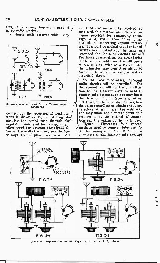
the local stations will be received atonce with this method since there is nomeans provided for separating them.Figs. 3, 4, and 5 show three othermethods of connecting crystal receiv-ers. It should be noticed that the tunedcircuits are substantially the same asdescribed for the tube circuits above.)For home construction, the secondariesof the coils should consist of 60 turnsof No. 20 B&S wire on a 2 -inch tube,the primaries may consist of about 30turns of the same size wire, wound asdescribed above.
i As the book progresses, differenti radio circuits wil be described. For
the present we will confine our atten-tion to the different methods used toconnect tube detectors so one may knowthe detector circuit from any other.
i The tubes, in the majority of cases, look1 the same regardless of whether they are
detectors or amplifiers; the only wayone may know the different parts of areceiver is by the method of connec-tion and the values of the parts used.
Figure 6 illustrates four generalmethods used to connect detectors. AtA, the tuning coil of an R.F. unit isconnected to the detector tube through
26 HOW TO BECOME A RADIO SERVICE MAN
fore, it is a very important part ofevery radio receiver.
A simple radio receiver which may
Schematic circuits of four different crystalreceivers.
be used for the reception of local sta-tions is shown in Fig. 2. All signalsstriking the aerial pass through thecrystal which rectifies (merely an-other word for detects) the' signal al-lowing the audio -frequency part to flowthrough the telephone receivers. All
hull- I11111111111r
Pictorial representation of Figs. 2, 3, 4. and 5. above.

HOW TO BECOME A RADIO SERVICE MAN
a condenser C2 and a resistor RI. Thismethod of connection is known as thegrid -leak and grid -condenser method,so called because during the operation,an electric charge is accumulated in
27
connected that detection of the signaltakes place without the use of con- '
densers or resistors.At D is shown a variation of the
method used at C, which is called a
Pictorial representation of the four detector circuits of Fig. 6.
condenser C2 which leaks off throughresistor Rl. This method of detectionis one of the most sensitive known andhas reigned supreme for many years.It has several disadvantages which ob-viate its present use. It is only sensi-tive on weak stil_ ,tions on the strongeroirei-TE distorts CoilsVerably. The tonequality der--)endi-- uponvalue of C2and RI; with use, the values change,especially with poor parts, and the re-ceiver suffers accordingly. With pre-sent-day highly sensitive receivers, thesignal strength applied to such a tubewould give results that are unrecog-nizable from the original.
At B the same arrangement is em-ployed but the grid -leak Rl is connectedfrom grid to filament instead of acrossthe grid condenser. The value of C2 isusually about .00025 mfd. and R1about 2 megohms (2 million ohms).
At C is shown a radically new de-tector circuit. A small battery is so,
power or linear detector. The qualityof output is better for strong signalsthan that for the methods described
Four types of detector circuits.

28 HOW TO BECOME A RADIO SERVICE MAN
above and therefore is more suitablefor present-day receivers.
Later on, a more detailed discussionof this part of a radio receiver will begiven in a discussion of the details ofAudio Frequency amplifiers.
Elements of a three -element tube andsocket.
The Audio AmplifierWe have seen so far, that an R.F.
amplifier is necessary in order to in-crease the sensitivity and selectivity ofa receiver, and a detector is used forobtaining the signal to be heard fromthe broadcasting station -wave. In orderto make the signal to be heard as loudas desired, an AUDIO AMPLIFIER isnecessary.
A complete discussion of audio am-plifiers will be given in the latter partof this book, but suffice it to say thatit is undesirable to use too many stagesof such amplification since distortion isbound to occur. In fact, present re-ceivers use only one stage of audioamplification fed from a power detec-tor of the type described above.
To the man who knows a little aboutelectricity, theory is not essential inorder to service some receivers, so thatmore time will be devoted to a dis-cussion of the various parts of a radioset, and, which is far more importantto the beginner in radio, how one mayrecognize one part from another.
The Vacuum TubeIn its essential form, a vacuum tube
is an evacuated glass vessel which con-
tains three essential elements-a grid,a filament, and a plate-for a three ele-ment tube. A cut -away view is shownin Fig. 7 and a diagram in Figs. 7Band 7C.
The filament is the V shaped threadof metal, the grid is the circular ar-rangement of wires and the plate oranode is the solid piece of metal sur-rounding the other two elements. Theirrelation to one another is indicated inFig. 7B, and their schematic arrange-ment in Fig. 7C. The grid and fila-ment is called the input circuit and theplate and filament is called the outputcircuit; the signal is fed into the tubevia the grid and filament, and is re-moved (amplified) from the tube viathe plate circuit. All apparatus con-nected to the input of the tube is call -
j ed the external input circuit and allapparatus connected to the plate is call-ed the external plate circuit. In somecases it is quite clear that only the ex-ternal circuit is under consideration, sothat the latter will be referred to asmerely the plate circuit.
The filament is heated by means ofa battery or transformer which is con-nected to the tube through prongs atthe base of the tube. In order to facili-tate connections and to support thetube, a socket is used which is similarIo that shown in Fig. 7D. The batterys connected to the socket as indicatedin Fig. 8A and shown schematically in
Pictorial and schematic diagram of fila-ment connections.
Fig. 8B. The "A" battery is the onethat heats the filament; it is connectedin series with the filament through theresistor R which is used for regulatingthe filament voltage.
The external grid circuit must beconnected to the grid and filament ofthe tube as stated above; the socket
_4.

HOW TO BECOME A
connections are shown in Fig 9A andthe schematic diagram (which is itsequivalent) in Fig. 9B. If an antennaand ground and a pair of telephone re-ceivers be connected as shown dotted, aone -tube receiver will be had.
Input and output circuits of a tube.
RADIO SERVICE MAN 29
1
Particular notice should be paid tothe fact that there is a "B" battery in-serted in the circuit. In order for atube to function properly, it is neces-sary always to connect a batery be-tween the plate and the output circuitas indicated; furthermore, the plateshould always be connected to the pos-itive side of the battery and the fila-ment to the negative. The tube willnot function if the "B" battery connec-tions are reversed. This is one of thefirst points to check when trouble-shooting on a radio set, especially onethat uses batteries.
Recent advances in the vacuum -tubefield brought forth the four and five ele-ment tubes. The physical construction- 3of the four -element tube is the sameas the three -element described above,with the exception of the insertion ofanother grid interposed between the in-put or control grid and the plate.
The theory of the vacuum tube is anextremely complicated treatise, but abrief explanation of what actually goeson inside is helpful in determining theaction of the circuit to which it is con-nected.
The filament of a tube, as statedabove, is heated by means of a battery,in a manner that is similar to that ofthe ordinary incandescent lamp. Whenit reaches a certain temperature, thefilament gives off small particles ofnegative electricity which are calledelectrons. These electrons being neg-ative, are attracted to the positivelycharged plate, since as we all know,like charges repel and unlike chargesattract. It is because this stream ofelectrons (which are evaporated fromthe filament in exactly the same man-ner that water evaporates when it isboiling) must be attracted to the plate,that the "B" batery with its positiveterminal connected to the plate, mustbe used. Thus, if the "B" battery volt-age were reversed, the plate would re-pel the electrons instead of attractingthem and the tube would not work.
In a three element tube, the grid isplaced between the filament and theplate so that all the electrons must passthrough the grating of the grid in or-der to reach the plate. Now if thegrid is made positive it will increasethe flow of electrons to the plate andif it is made negative, it will decreasethe flow of electrons. It is clear, then,that the condition of the grid (whether
Elements of a screen -grid tube.
it is positive or negative) determinesthe amount of electrons flowing to theplate. Because of this controlling ac-tion of the grid which is connected tothe input circuit of the tube, it is calledthe control grid. In other words, thatgrid in the tube which is connected tothe input circuit is called the Controlgrid, regardless of where they othergrids connect.
To aid the tube, an initial voltage,obtained by means of a battery or aresistor, is connected to the grid. Thisvoltage is very important and deter-mines whether the tube is an amplifier

30 HOW TO BECOME A RADIO SERVICE MAN
Ior a detector. This voltage is calledthe "C" voltage or "C" bias.
The arrangement of the tube ele-ments is depicted in Fig. 10A and itsschematic circuit in Fig. 10B. The tubeis so constructed that the control gridconnection is made to a small cap on
THIMBLE ORCATHODE
"HEATER
GRID
FIG.Ii
PLATEPLATE CIRCUIT
CATHODE"K"
(NI:EATER
TOHEATERVOLTAGE'
Circuit of heater and cathode connections.
the top of the tube, the screen grid (theother grid is called a screen grid) con-nection being made to the same prongof the socket as the input grid of thethree -element tube.
Because electric receivers must havethe tubes operate from alternating cur-rent, certain tubes have been designedwith a slightly different filament ar-rangement than that discussed above.The filament is there as before, onlynow we will call it a heater; surround-ing this heater, but insulated from it,there is a thimble which actually emitsthe electrons which work the tube. Nowit should be remembered that the heat-er is connected to a source of potentialexactly as described above, only the ex-ternal grid and plate circuits are madeto this thimble or cathode in exactlythe same manner as they were madeto the filament described above. Thisis indicated in Fig. 11A and B.
This heater may be used in three-,four-, or five -element tubes dependingupon the design. Five element tubesare constructed exactly the same as the
N. four -element described above, with theaddition of a third grid internally con-nected to the filament. Its presence,therefore, does not directly change theoutline given above.
From the above, it will be realizedthat a theoretical knowledge is notnecessary in order to construct or ser-vice some receivers because the funda-mental circuit is the same in every re-ceiver. This point will be discussedfurther later on.
The purpose of the vacuum tube, asstated above, is to amplify or detect asignal, depending upon its type of con-nection. It will be instructive now, todiscuss the R.F. units used in radiosets and then the units used in audiowork.
R.F. UnitsSince the external input circuit of
any vacuum tube is fundamentally thesame, the only difference between anR.F. and an A.F. unit is in its construc-tion. Fig. 12 shows a schematic dia-gram of a two stage R.F. amplifierwhich directly precedes the detectortube. All filament and "B" batteryconnections have been omitted for thesake of simplicity but they are givenin another section of this book.
An examination of the input circuits(that circuit which is connected be-tween grid and filament) of the tubeswill show that they are all the sameas the aerial circuits discussed above.If a type B (Fig. 1) antenna coil isused, the primary P is usually woundwith about 10 turns of No. 22 wireeither at one end or spread over theentire secondary. The secondary S iswound with about 60 turns of the samesize wire on a 2 in. diameter tube.The only thing that separates the pri-mary from the secondary is air, no ironbeing used in R.F. transformers. Fig.13 shows a pictorial layout of a typi-cal R.F. transformer, connected in theone -tube set described above. The
Antenna and R.F. coils.
transformer is light, small, and is usu-ally mounted above and away from anymetal parts of the set. In some casesit is enclosed in a can or shield in orderto isolate it from the rest of the re-ceiver. In this respect, R.F. trans-formers are easy to recognize. Theymay vary slightly in size or shape, but
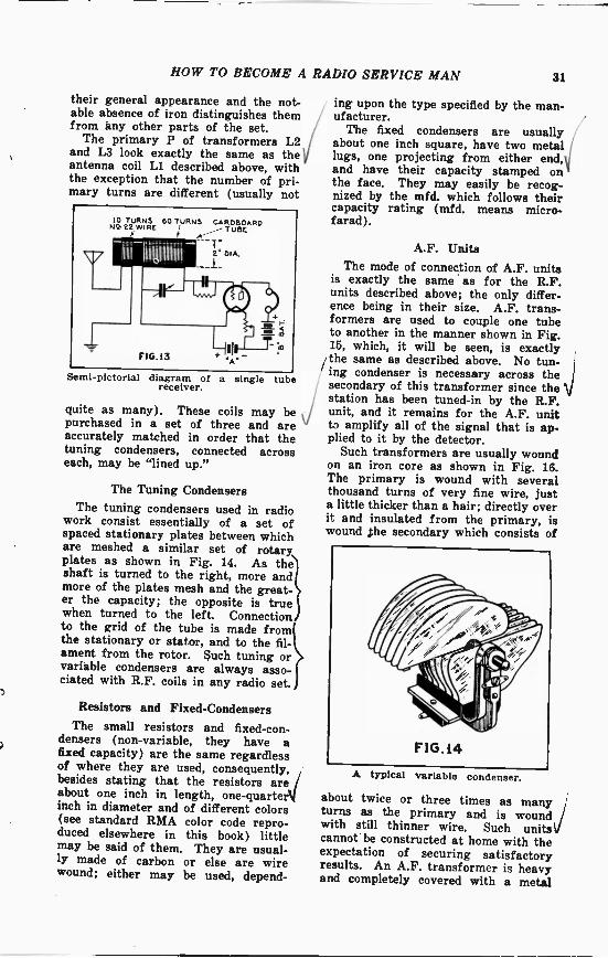
HOW TO BECOME A RADIO SERVICE MAN 31
their general appearance and the not-able absence of iron distinguishes themfrom any other parts of the set.
The primary P of transformers L2and L3 look exactly the same as theantenna coil LI described above, withthe exception that the number of pri-mary turns are different (usually not
10 TURNSN2-22 WIRE
ir
60 TURNS CARDBOARDTUBE
FIG. l3
T-2" DIA.
Semi -pictorial diagram of a single tubereceiver.
quite as many). These coils may bepurchased in a set of three and areaccurately matched in order that thetuning condensers, connected acrosseach, may be "lined up."
The Tuning Condensers
The tuning condensers used in radiowork consist essentially of a set ofspaced stationary plates between whichare meshed a similar set of rotaryplates as shown in Fig. 14. As theshaft is turned to the right, more andmore of the plates mesh and the great-er the capacity; the opposite is truewhen turned to the left. Connectionto the grid of the tube is made fromthe stationary or stator, and to the fil-ament from the rotor. such tuning orvariable condensers are always asso-ciated with R.F. coils in any radio set.
Resistors and Fixed -CondensersThe small resistors and fixed-con-
densers (non -variable, they have afixed capacity) are the same regardlessof where they are used, consequently,besides stating that the resistors are /about one inch in length, one-quarterMinch in diameter and of different colors(see standard RMA color code repro-duced elsewhere in this book) littlemay be said of them. They are usual-ly made of carbon or else are wirewound; either may be used, depend-
ing upon the type specified by the man-ufacturer.
The fixed condensers are usuallyabout one inch square, have two metal,'lugs, one projecting from either end,Vand have their capacity stamped onthe face. They may easily be recog-nized by the mfd. which follows theircapacity rating (mfd. means micro -farad ).
A.F. UnitsThe mode of connection of A.F. units
is exactly the same as for the R.F.units described above; the only differ-ence being in their size. A.F. trans-formers are used to couple one tubeto another in the manner shown in Fig.15, which, it will be seen, is exactlythe same as described above. No tun-ing condenser is necessary across thesecondary of this transformer since the Vstation has been tuned -in by the R.F.unit, and it remains for the A.F. unitto amplify all of the signal that is ap-plied to it by the detector.
Such transformers are usually woundon an iron core as shown in Fig. 16.The primary is wound with severalthousand turns of very fine wire, justa little thicker than a hair; directly overit and insulated from the primary, iswound ,the secondary which consists of
A typical variable condenser.
about twice or three times as manyturns as the primary and is woundwith still thinner wire. Such units'icannot be constructed at home with theexpectation of securing satisfactoryresults. An A.F. transformer is heavyand completely covered with a metal

32 HOW TO BECOME A RADIO SERVICE MAN
shield. The various terminals P, +B,G, and F, are clearly marked. No trou-ble should be experienced in recogniz-ing this unit. Its representation indiagrams is always accompanied bythin, straight lines between the pri-mary and secondary, which indicate thepresence of iron, and the s ce ifiron always means a unit.
A choke coil or merely a choke is adevice that is inserted in a circuit inorder to prevent current (A.C. only)from flo_wirri through the circuit iniv Era the choke is inserted. Thus, ifan A.F. choke is inserted in series withthe plate lead of an A. F. amplifiertube, no A.F. signal will pass throughit, and therefore no signal will be heard.In a similar manner, if an R.F. chokebe inserted in the plate lead of an R.F.amplifier, no signal will be heard. A.F.chokes should only be used in A.F. cir-cuits and likewise, R.F. chokes shouldonly be used in R.F. circuits. Tyshould never be interchanged.
Construction of R.F. Chokes
An R.F. choke consists of severalhundred turns of very fine wire, usual-ly wound on a spool or a bobbin ofwood (similar to the type used onsewing machines). It has no iron andtherefore is light; the spool beirfg aboutone inch in diameter. The primary coilin C (of Fig. 1) is an R.F. choke and
Connections of an A.F. transformer.
is mounted as shown in Fig. 17. It isusually wound with No. 28 or 30 B & Swire and has two terminals protruding.Its connection is always indicated inthe diagram of the set.
Construction of A.F. Chokes
Audio -frequency chokes are heavymassive affairs wound with several -thousand turns of enameled wire on athick (about one square inch in cross-
sectional area) core. It, too, has twoterminals from which connections maybe made, but there can be no confusionbetween this and an R.F. unit. If con-fusion does arise, it is between an A.F.
Upper left, A.F. transformer construction.Upper right, R.F. transformer construc-tion. gerow, A.F. choke construction.
choke and transformer. One may tellthe difference between them, however,by the fact that a choke has but twoterminals while the transformer hasfour; also, of course, the label may beconsulted when in doubt. A pictor-ial view of a typical A.F. choke isshown in Fig. 18. The method of con-nection will be described during thecourse of the book.
The Power Unit
Ever since the advent of electricallyoperated receivers, there must be con-nected or housed in the set certainpieces of apparatus that are used totake the place of the "A" and "B" bat-teries formerly used. These pieces ofapparatus, when built in a unit, arecalled the power unit.
Since ordinary radio sets require "B"voltages of from 20 to 500, means mustbe provided to raise the ordinary 110 -volt light -lines to the required value.To accomplish this, a device called apower transformer is used. In its es-sential form it consists of a large coreof iron wound with several coils ofwire. One coil connects directly to the

HOW TO BECOME A RADIO SERVICE MAN 83
light line, and therefore is called theprimary. Another, very much largerwinding, is wound directly over theprimary with smaller wire (about No.28). From this winding the high volt-age necessary for the "B" supply is ob-tained. This winding is called thehigh -voltage secondary. To supply thevoltage necessary for the heaters ofcertain tubes, smaller windings (calledlow -voltage secondaries) are used. Apictorial representation of these wind-ings is given in Fig. 19A and a schem-atic diagram in Fig. 19B. In certaincases a tap (another word for a con-nection) is taken from the center of thehigh voltage winding as shown.
Now that the proper voltage has beenobtained for the "A" and "B" supply,the next problem is to convert the highvoltage A.C. into high voltage direct
TO lt0 V. HIGH VOLTAGESECONDARY
PRIMARY
t42
52O
FSECONDARY
LOWVOLTAGE
FIG. 19
Pictorial and schematic connections of apower transformer.
current (D.C.). This is accomplishedby means of a rectifier tube. A powerrectifier tube is similar to the threeelement tube described above, but hasno grid-just a filament and a plate.The filament is lit by means of a lowvoltage secondary of the power trans-former and is connected as shown inFig. 20.
Now in normal operation, the voltageacross the secondary of the transform-er changes from positive to negative120 times per second. Thus, 60 timesa second the plate of the tube is posi-
tive and 60 times a second it is nega-tive. As we have seen, the tube will, /not work when the plate is negative-Vonly when it is positive. The result is
A half -wave rectifier circuit.
that the voltage has one part of itchopped off-that part that is appliedto the tube when the plate is negative.Since only half of the voltage is used,the circuit is a half -wave rectifier.
To utilize all of the voltage that isapplied to the tube, a slightly differenttype of tube is used. It has two platesinstead of one-and is connected as in-dicated in Fig. 21. The outside termin-als of the high -voltage secondary con-nect to both plates of the tube and thecenter -tap is the negative of the D.C.voltage output. With this arrange-ment, when the plate of one tube ispositive, the plate of the other is nega-tive, and vice versa. With this con-nection, both halves of the voltage areused.
The Filter Unit
Since the output voltage of the rec-tifier varies in strength, some meansmust be used to smooth it out, or makeit unvarying in amount so that it isequivalent to batteries which it is re-placing. In our discussion of A.F.chokes, it was stated that they are usedwhenever A.C. or varying currents areto be suppressed, they may then be
A full -wave rectifier circuit.
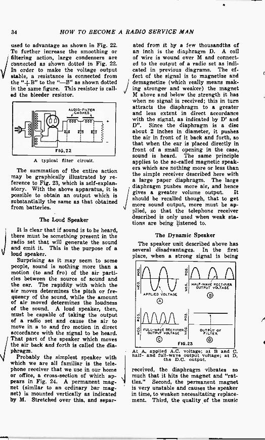
34 HOW TO BECOME A RADIO SERVICE MAN
used to advantage as shown in Fig. 22.To further increase the smoothing orfiltering action, large condensers areconnected as shown dotted in Fig. 22.In order to make the voltage outputstable, a resistance is connected fromthe "+B" to the "-B" as shown dottedin the same figure. This resistor is call-ed the bleeder resistor.
A typical filter circuit.
The summation of the entire actionmay be graphically illustrated by re-ference to Fig. 23, which is self-explan-atory. With the above apparatus, it ispossible to obtain an output which issubstantially the same as that obtainedfrom batteries.
The Loud Speaker
It is clear that if sound is to be heard,there must be something present in theradio set that will generate the soundand emit it. This is the purpose of aloud speaker.
Surprising as it may seem to somepeople, sound is nothing more than amotion (to and fro) of the air parti-cles between the source of sound andthe ear. The rapidity with which theair moves determines the pitch or fre-quency of the sound, while the amountof air moved determines the loudnessof the sound. A loud speaker, then,must be capable of taking the outputof a radio set and cause the air tomove in a to and fro motion in directaccordance with the signal to be heard.That part of the speaker which movesthe air back and forth is called the dia-phragm.
Probably the simplest speaker withwhich we are all familiar is the tele-phone receiver that we use in our homeor office, a cross-section of which ap-pears in Fig. 24. A permanent mag-net (similar to an ordinary bar mag-net) is mounted vertically as indicatedby M. Stretched over this, and separ-
ated from it by a few thousandths ofan inch is the diaphragm D. A coilof wire is wound over M and connect-ed to the output of a radio set as indi-cated in previous diagrams. The ef-fect of the signal is to magnetize anddemagnetize (which really means mak-ing stronger and weaker) the magnetM above and below the strength it haswhen no signal is received; this in turnattracts the diaphragm to a greaterand less extent in direct accordancewith the signal, as indicated by D' andD". Since the diaphragm is a discabout 2 inches in diameter, it pushesthe air in front of it back and forth, sothat when the ear is placed directly infront of a small opening in the case,sound is heard. The same principleapplies to the so-called magnetic speak-ers which are nothing more or less thanthe simple receiver described here witha large paper diaphragm. The largediaphragm pushes more air, and hencegives a greater volume output. Itshould be recalled though, that to getmore sound output, more must be ap-plied, so that the telephone receiverdescribed is only used when weak sta-tions are being listened to.
The Dynamic SpeakerThe speaker unit described above has
several disadvantages. In the firstplace, when a strong signal is being
a
HALF -WAVE RECTIFIERki OUTPUT VOLTAGE
APPLIED VOLTAGE
0
FULL -WAVE RECTIFIERSZ OUTPUT VOLTAGE z
F10.23
OUTPUT OFFILTER
At A, applied A.C. voltage; at B andhalf- and full -wave output voltage; at
the D.C. output.C.D,
received, the diaphragm vibrates somuch that it hits the magnet and "rat-tles." Second, the permanent magnetis very unstable and causes the speakerin time, to weaken necessitating replace-ment. Third, the quality of the music

HOW TO BECOME A RADIO SERVICE MAN
Wt\xxxv.,,,N,NmAsm,ANAmS
A cross-section view of a simple tele-phone receiver. The coil, wound overmagnet M connects to the output of thereceiver.
or speech is not very good with strongsignals. To obviate the above effects,a new type of speaker has been evel-oped and is used to the exclusion of allother types in present receivers-thedynamic speaker.
The first requirement of such aspeaker is that no permanent magnetsare used, a cross-section of such a unitis shown in Fig. 25. A large, heavy, iron\case (M) is built in the form of a cylin-der with a large center portion MN.Over this center portion is wound manyturns of fine wire (similar to that ofan A.F. choke), the terminals of whichconnect to a D.C. source of supply.This source may be batteries, a separ-ate rectifier, or in many cases thiswinding (called the field) is used as oneof the chokes in a filter unit. In anyevent, the bar MN is magnetized. Overone end of the bar, but separated fromit, is placed a small coil, wound witha few turns of fine wire; this coil iscalled the voice coil and connects di-rectly to the output of the radio set.When a signal is impressed across theterminals of the voice coil, it generatesa magnetic field (exactly similar tothat of the field coil); this field is vary -
3 ing according to the variations of thesignal and reacts with the steady fieldto produce motion of the voice coil.Now, rigidly attached to this voice coilis a large cone -shaped piece of paper/
TO RADIO 'BAFFLESET
FIG.25
86
Cross section view of a typical dynamicspeaker. To the right is shown thebaffle board which is always used withsuch speakers.
which is called the cone; this cone mov-ing with the voice coil to produce sound.
A signal of almost any strength maybe applied to such a speaker, the limi-tations only being the horizontal dis-tance the voice -coil can move, which isabout one -eighth of an inch. The qual-ity obtained from such a speaker isexcellent on large volume and is in noway comparable to the Magnetic speak-ers described.
The cone is centered on the bar bymeans of a spider shown in the figure;if the cone is off center, the speakerwill rattle. The easiest way to centera cone is to loosen the screw in thecenter of the spider and move the voice-coil from side to side until the rattlestops on the strongest signal that canbe tuned in.
In order to increase the response ofthe very low notes, a large board is at-tached to the cone by means of brac-kets as shown in the right-hand sketch /of Fig. 25. This board should be atleast one foot in length on each sidein order for it to be effective. Thisboard is called a baffle and is to befound on every radio set using a dy-namic speaker.
Connections from the voice -coil tothe final tube in the set is usually madeby means of an output transformerwhich is described in another sectionof this book.
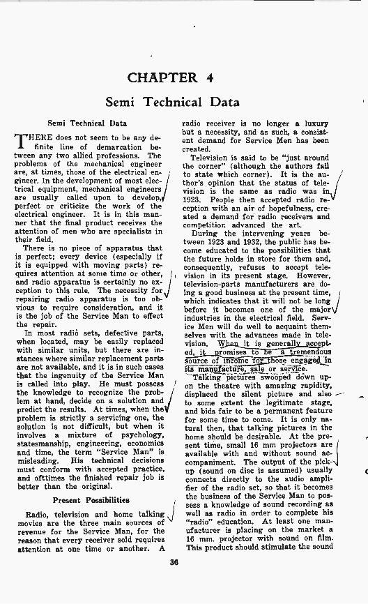
CHAPTER 4
Semi Technical DataSemi Technical Data
THERE does not seem to be any de-finite line of demarcation be-
tween any two allied professions. Theproblems of the mechanical engineerare, at times, those of the electrical en-gineer. In the development of most elec-trical equipment, mechanical engineersare usually called upon to develop,perfect or criticize the work of theelectrical engineer. It is in this man-ner that the final product receives theattention of men who are specialists intheir field.
There is no piece of apparatus thatis perfect; every device (especially ifit is equipped with moving parts) re-quires attention at some time or other,and radio apparatus is certainly no ex-ception to this rule. The necessity forrepairing radio apparatus is too ob-vious to require consideration, and itis the job of the Service Man to effectthe repair.
In most radio sets, defective parts,when located, may be easily replacedwith similar units, but there are in-stances where similar replacement partsare not available, and it is in such casesthat the ingenuity of the Service Manis called into play. He must possessthe knowledge to recognize the prob-lem at hand, decide on a solution and ,
predict the results. At times, when they'problem is strictly a servicing one, thesolution is not difficult, but when itinvolves a mixture of psychology,statesmanship, engineering, economicsand time, the term "Service Man" ismisleading. His technical decisionsmust conform with accepted practice,and ofttimes the finished repair job isbetter than the original.
Present Possibilities
Radio, television and home talkingmovies are the three main sources ofrevenue for the Service Man, for thereason that every receiver sold requiresattention at one time or another. A
36
radio receiver is no longer a luxurybut a necessity, and as such, a consist-ent demand for Service Men has beencreated.
Television is said to be "just aroundthe corner" (although the authors failto state which corner). It is the au-thor's opinion that the status of tele-vision is the same as radio was in1923. People then accepted radio re-ception with an air of hopefulness, cre-ated a demand for radio receivers andcompetition advanced the art.
During the intervening years be-tween 1923 and 1932, the public has be-come educated to the possibilities thatthe future holds in store for them and,consequently, refuses to accept tele-vision in its present stage. However,television -parts manufacturers are do-ing a good business at the present time,which indicates that it will not be longbefore it becomes one of the majorindustries in the electrical field. Serv-ice Men will do well to acquaint them-selves with the advances made in tele-vision. when it is generally accept-ed, it promises to be a tremendoussource of income for those engaged inits manufacture, sale or service.
Talking pictures swooped down up-on the theatre with amazing rapidity,displaced the silent picture and alsoto some extent the legitimate stage,and bids fair to be a permanent featurefor some time to come. It is only na-tural then, that talking pictures in thehome should be desirable. At the pre-sent time, small 16 mm projectors are ,
available with and without sound ac-companiment. The output of the pick-up (sound on disc is assumed) usuallyconnects directly to the audio ampli-fier of the radio set, so that it becomesthe business of the Service Man to pos-sess a knowledge of sound recording aswell as radio in order to complete his"radio" education. At least one man-ufacturer is placing on the market a16 mm. projector with sound on film.This product should stimulate the sound

a
HOW TO BECOME A R
talking pictures in the home to agreater extent than the former method.A slight knowledge of optics, screens,illumination, etc., should be added tothe Service Man's store of knowledgein order to effectively service home talk-ing equipment.
Future Outlook
With the above facts in mind, it isnot difficult to predict future possibil-ities. The fields of radio, television andhome talking pictures are so inter-woven that it is impossible to speakof one field without reference to theother. With proper advertising it iseasy to see that the future of radio isvery bright indeed.
There seems to be a misleading rumorto the effect that the radio business is"slow" during the summer months.While this was true ten years ago, itis not indicative of present conditions.The radio business is not consideredgood during the summer for the sim-ple reason that people are not homeduring the summer. With the adventof the automobile receiver, however,this difficulty is obviated. With pre-sent day high signal-to-noise ratio re-ceivers, the problem of static interfer-ence is minimized, and in the future,will probably be eliminated altogether.With a little effort, the radio businessmay be made to be an "all year round"proposition.
Requirements of a Service Man
Of all the requirements of a ServiceMan, that of technical knowledge isparamount. Contrary to some opinions,a Service Man obtains a livelihood bywhat he knows rather than by what hedoes. It does not take much knowledgeto replace a defective transformer ina receiver, but to know which trans-former to replace may, at times, re-quire considerable skill. Regardless ofany other qualities a man may possess,his opinion is held in high esteem amongfellow Service Men if he "knows hisstuff."
Personality is an important factorthat enters into the success of a ServiceMan. Suppose, for example, a man, inan answer to a service call, is informedthat a certain receiver is "noisy." Up-on investigation he finds that it is due
ADIO SERVICE MAN 37
to interference caused by an oil -burnermotor in the cellar, and informs thecustomer of his findings. This custo-mer may or may not believe him, andmay or may not give him the job ofeliminating the interference, dependingupon the manner in which the subjectis approached and the personality ofthe Service Man. A magnetic person-ality instantly instills confidence, andconfidence is an all important factorin building up a business. A ServiceMan should be pleasing, neat, well -dressed and attempt to convey the airof a physician rather than that of alaborer; for after all, a Service Manmust sell the customer on the idea thathe (the Service Man) is right and thathis word is law-not by ferocity andsarcasm but by a consistent, diplomat-ic, pleasing approach that is indicativeof sure knowledge. This point is ex-tremely important, especially for theman who desires to build up his ownbusiness.
Circuit Diagrams
A circuit diagram is merely a meansof conveying knowledge. In order to
circuit of a simple 2 -tube re-generative receiver.
indicate how certain pieces of equip-ment are connected, each and every partof the equipment is represented by asymbol and the symbols are connectedtogether by lines which represent wires.In this manner the mode of connectionof the apparatus is indicated.
Suppose, for example, it is desiredto translate a simple two tube diagraminto words. Consider the circuit ofFig. 26. As can be seen, it consists oftwo tubes, a multiplicity of coils, con -
Schematic

4
38 HOW TO BECOME A RADIO SERVICE MAN
densers and telephone receivers. Letus examine in detail just what the var-ious parts mean.
The antenna and ground connect tothe two ends of a coil marked P. ThisIs the primary coil of the radio -fre-quency transformer Ti. All the energycollected by the antenna is in the coilP. By induction it generates a volt-age across the coil S; this voltage oper-ating the tube V1 and in turn V2, am-plifying the signal until it is loudenough to hear. Now in order to ob-tain the greatest amount of response,the coil S must be tuned to resonancewith the signal, and this is accomplish-ed by the condenser Cl.
In America, the broadcast stationscover the band from 550 to 1500 kc.(kilocycles), and thus is becomes neces-sary to have the coil S and the con-denser Cl of such size that they cantune over this band easily. The an-tenna coil (or primary coil) P is mere-ly used for the purpose of collectingsufficient energy to actuate the tube;If it is too large, the set will tune"broad" and if it is too small, it willproduce a small or weak signal. Justhow the primary is designed dependsupon the particular receiver in use, andit is not the purpose of this book to en-ter into design considerations. All thatit is necessary to know (so far asreading diagrams is concerned) is thatthe primary is not ordinarily tuned.The coil and condenser (called thetuned circuit) connects to the grid andfilament of the tube through the grid -condenser C3 and the grid -leak R2,which are necessary in order for thetube to detect.
The plate of the tube connectsthrough a coil to the primary of theaudio -frequency transformer T2. Insimple terms, the coil T has two con-nections after it is wound, the begin-ning of the coil and the end. One ofthese connections goes to the prongof the tube socket marked "P" and theother to the terminal of the A.F. trans-former marked "P". In other words,when the symbol of a device shows threeterminals, then there must be at leastthree wires going to that device; ifnot, then the diagram should be checkedcarefully for errors.
During the author's many years asan instructor, he has found one method
of indicating how diagrams should beread that seemed to be very compre-hensible. It can easily be appreciatedby the reader that although it is easyto point out how a particular diagramshould be read, it is impossible to ex-plain how all radio diagrams should beread unless general r'les are laiddown.
Fortunately, the input circuit of anyvacuum tube is generally the same re-gardless of whether it is an oscillator,amplifier or detector. Stripped of un-essential details, the input circuit ofany tube may be represented by Fig. 27.It is seen that a coil L is connected di-rectly between the filament and thegrid. Whether the coil has a condenseracross it or not has nothing to do withthe interpretation of the diagram im-mediately, the fact remains that be-tween the grid and filament of thetube there must be connected a circuit;whether this circuit is a resistor, oran inductance has nothing to do withthe fact that there must be a continu-ous circuit between the grid and fila-ment. This point is extremely import-
and should be carefully borne inmind when tracing diagrams.
The same requisite is true of theplate circuit; regardless of what pathone must trace through the plate cir-cuit, there must be a complete circuitbetween plate and filament. It is evi-dent that in a three element tube thefilament is the common point fromwhich all voltages are measured. Inpictori..I form, the grid and plate cir-cuits may be shown as in Fig. 28. Witha true appreciation of the above state-ments, one is able to fathom the mostcomplex radio receiver diagrams usedin modern receivers.
Let us see how the above holds truein analyzing the two tube set of Fig.26. Starting with the grid of Vi, wepass through R2 (and of course C3, al-though C3 does not offer a continuouspath for D.C. and therefore should notbe considered) then through winding Sof the R.F. transformer T1 and backto the filament. Thus, the first pre-requisite is satisfied. From the plateof V1 we pass through the primary ofthe A.F. transformer T2 to the "B"plus tap, through the "B" battery andresistor Rl to the filament. Thus, thesecond prerequisite is satisfied. Con-

HOW TO BECOME A R
sidering tube V2, we pass from thegrid through the "C" battery to thefilament; from its plate through thephones and "B" battery, through Illto its filament. In all of the abovecases, it is absolutely essential that wetrace from the grid of a particulartube to its filament and from the plateto its filament. In this manner eachtube may be considered a distinct andseparate unit, and may in general bestudied in detail without reference toany other tube.
Advanced Circuit Study
The simple circuit of Figs. 27 and28 will be used as the foundation upon
I
which all additional data rests.One problem which most Service Men
have difficulty with is the determina-tion of just what resistor or resistors /are used to obtain "C" bias for a giventube. Again we may apply a simplerule, which if followed, will make thesolution of the most complex circuit )
Left, input circuit; right, block diagramf input and output circuit of a tube.
relatively easy. It may be stated de-finitely that the voltage included be-tween the grid return and the filament(or the heater in the case of heater typetubes) constitutes the "C" bias for thattube. Thus in the circuit of Fig. 29, re-sistor R is the grid circuit, 4 being thegrid lead, 3 being the grid return; lead3 connects directly to point 2. Since the"C" bias is the voltage between thegrid return and the filament, then thebias must be the voltage across R1,or between points 1 and 2. The platecurrent flows between plate and fila-ment and hence point 1 is positive withrespect to point 2, or point 2 is nega-tive with respect to point 1. The sameholds true for the filament current andhence the grid return is negative withrespect to its filament. In ordinaryoperation, no current flows in the gridcircuit and hence through R, therefore
ADIO SERVICE MAN 39
there is no voltage across R. The po-tential of the grid is thus the same asits grid return, with the result that theactual grid voltage ("C" bias) is thedrop across Rl. If the polarity of the"A" battery were reversed, the grid
Typical input circuit showing grid -biasresistor.
would be positive with respect to thefilament since the filament current isusually far greater thin the plate cur-rent. In modern receivers, the "C" biasis determined solely by the plate cur-rent, so that the direction of filamentcurrent has no bearing on the subject
Let us consider a more complex cir-cuit such as that illustrated in Fig. 30.The plate currents of both V1 and V2must flow from the "B" plus throughthe tube to the cathode (heater tubesbeing used now for the sake of varia-tion) and then through RI (from point2 to point 1) in order to reach the "B"minus. The "C" bias for both tubes
Diagram showing how two tubes obtaintheir bias from a single resistor.
is then the voltage drop across R1 andis equal to the value of RI in ohms mul-tiplied by the sum of the plate currentsof both tubes.

40 HOW TO BECOME A
It is now a very easy matter to showhow a modern automatic volume con-trol functions. When a signal is tooloud, it may be reduced by making thegrids of the amplifier tubes more nega-tive. This may be done automatically
Connections showing the principle uponwhich one type of automatic -volumecontrol works.
by causing the plate current of a diode(two element) detector to flow througha resistor, and having this resistor inseries with the grid return leads ofthe amplifier tubes. This is illustratedin Fig. 31.
The plate currents of both V1 andV2 must flow through R1 in order toreach "B" minus. The current throughthe diode, (when a station is tuned in)must flow through R2 as well as Rl. Nowthe "C" bias for any tube was definedas the voltage between the grid re-turn and its particular cathode. Trac- b
Input circuit showing the use of a grid -filter.
1 ing through the grid returns of botht V1 and V2, we find that the total
voltage between their grid returns antheir cathodes is the sum of the volages across R1 and R2. The voltsacross R2 varies directly as the si
RADIO SERVICE MAN
strength, and hence a smooth controlof volume is automatically secured.Other systems use a separate tube tosecure the desired result, but the fun-damental theory of operation is thesame.
It should be particularly noted thatwe determined how the automatic vol-ume control functioned and analyzedthe grid circuits of three tubes by mere-ly following the simple rule outlinedabove. The plate and power circuitswere not shown for the sake of clarity,and in analyzing diagrams only onecircuit should be investigated at a timeanyway, so that the simplified diagramshown in Fig 31 is indicative of whatone should concentrate on when study-ing radio diagrams.
Grid FiltersA very interesting case illustrating
he general rules outlined above isound in the study of grid -circuitJ:sitssitfilte{s.
In Itigh_gr_agleAudiatura* ts) keep-the-Aignal_tertain tube entirely within _the . tubecirspit. This is especially useful inhigh -gain amplifiers where the slight-est feed -back may cause oscillations.
Consider the circuit of Fig. 32. Fromour previous analysis we know that thegrid bias resistor is RI and, let us say,is about 2000 ohms. The signal im-pressed across the coil L actuates thetube and therefore should be as greatas possible. Now the effect of the grid -bias resistor is to reduce the signalvoltage applied_ between the grid andcathode, so that it is necessary to shuntthe resistor R1 with a condenser whosereactance (the o osition to flow ofcurrent of a condenser at the lowestfle-quency to be received is about one -tenth the value of Rl. In audio ampli-fier work, this may mean the use ofa very large (and consequently expen-sive) condenser. If we now insert alarge resistor R2 in the circuit asshown, then the condenser may be madevery much smaller by virtue of the factthat the resistance path from the gridreturn to the cathode is deliberatelymade larger by the insertion of R2.
Since the value of the reactance ofthe capacity should be one -tenth thevalue of the resistance R1, then it canbe made about one -tenth the size thatit would have if R2 were not there due

HOW TO BECOME A
to the insertion of R2, and at the sametime do the same amount of filter-ing. Resistor R2 does not contributeto the "C" bias because the plate cur-rent does not flow through it; it (theplate current) returns to the "B" min-us immediately upon leaving Rl. Itshould be pointed out that the grid cir-cuit of the tube consists of L, C, andR2. The plate circuit may also have afilter for the same reasons as discussedfor the grid circuit.
At this time a few pointers regard-ing the c(mstruction of receivers are inorder. First,
andand plate leads
should be ass and as directas pu-sible; this is very important in modern
.011.0receivers. Second, alL leads_surailagA.C.. such as filgaggijeads, should betwisted. When twisted, the magneticarr of one lead neutralizes the fieldof the other, resulting in an externalfield of practically no strength. Thepower unit should be kept as far fromthe A.F. end of the set as possible inrder to avoid induction.
Uses of Voltmeters and AmmetersIn the early days of radio broadcast-
ing, Service Men had but two pieces oftest equipment-a voltmeter and a mil-liammeter. The receivers were simplein those days and consequently addi-tional apparatus was considered unes-sential and in some cases slightly un-ethical. With the advent of the eletric receiver, however, design advancedto such a stage that it became almostimpossible to intelligently test a re-ceiver unless some means was employ-ed to measure all voltages and currentsboth accurately and swiftly-hence themodern set analyzer.
To attempt to describe a simple test-er without illustrating in detail the /theory upon which it functions would/be unwise. Therefore we will devotesome time to a discussion of some ofthe problems encountered in measur-ing work and then proceed to show howthey may be minimized.
Suppose it is desired to measure thegrid voltage of a tube connected asgrawn inrrig. 29. Now grid voltage ismeasured between the grid and the fila-ment (or the cathode in heater -typetubes) and therefore it is necessary toinsert the voltmeter between points1 and 4. If this is done, a reading will
RADIO SERVICE MAN 41
be obtained, but not the true reading.The reason will be apparent when thesame circuit is redrawn as in Fig. 33.The "C" bias resistor has been re-placed by the battery E which, let ussay, has a voltage of 6. If the volt-meter is to read correctly, it too mustread 6 volts. Usually the resistor Rhas a value of about 1,000,000 ohms; ifthe grid circuit is that of an audioamplifier, the resistance of the second-ary of the transformer may be about100,000 ohms. Let us assume the lat-ter figure.
Above, circuit showing the connectionso a grid circuit voltmeter. Below, typi-cal 1 -tube receiver.
If a low resistance voltmeter is used(100 ohms per volt), then the meterwill have a resistance of only 1,000ohms if the 10 -volt scale is used. Thecurrent flowing in the circuit would be6 divided by 101,000 or .000059 am-peres. The voltage drop across R is 5.9volts, leaving a voltmeter reading ofonly .1 -volt. If a high resistance me-ter is used, with a value of 1,000 ohmsper volt (a total resistance of 10,000ohms for the 10 -volt scale) the readingof the voltmeter would be .55 volts. Itin seen then, that the higher the re-sistance of the meter, the more accur-ate the reading obtained.
It is not practical to make meterswith a resistance greater than 1,000ohms per volt, so that in circuits hav-ing a high resistance, the correct biascan never be measured. In R.F. and

6 Tam tio0(0 ti s
.0010 1-40-04AcRtic42 HOW TO BECOME A RADIO SERVICE MAN
detector stages, where the secondaryof the transformer has practically noresistance, it is possible to obtain cor-rect readings. In cases of circuits hav-ing a high resistance, the grid bias maybe accurately measured by 'removingthe chassis and connecting the volt-meter across the bias resistor R1 inFig. 29.
The same trouble holds true for theplate circuit-actually true readings cannever be obtained if the load (outputcircuit) has a high resistance. Thedrop in voltage in the plate circuit willnever be as much (in percent) as inthe grid circuit; for instance, if thetrue plate voltage (measured fromplate to filament-or cathode) is 100volts, and the voltmeter reads 75 ina fairly high resistance circuit, then itmay be assumed that the plate voltageis correct. Extreme precision is notjustified in service work- ccuribaFi 10 __pgi,_. is close enough oral purposes.
-From the foregoing, it is clear thatfor ideal voltage measurements, the re-sistance of the voltmeter should bemuch higher than the resistance acrosswhich it is connected. A good rule toremember is that the resistance of themeter should be at least ten times theresistance of the circuit being meas-ured.
The Ammeter
Just as the voltmeter is used formeasuring voltage, the ammeter isused for measuring current. The move-ments of the meters are the same, theonly difference being that a high re-sistance is connected in series with themovement in the case of the voltmeter,and a low resistance connected acrossthe movement when it is to be usedas an ammeter. This point will be dis-cussed in greater detail later on.
The ammeter being a low resis anceunit that is connected in ettF wiffir circuit through which tie currentis to be measured, it might seem thatits location in the circuit is arbitrary.This is only true when its resistance islow as compared with the rest of thecircuit; when the current through thecircuit is small; and, if a voltmeter isused, the current that is consumed bythe meter is not recorded by the am-meter.
The above statement regarding theplacement of the ammeter is not reallyimportant in radio service work, butit was mentioned because it accountsfor some of the errors that occur insome types of measuring instruments.
The Milliammeter(Unlike power work, the currents in-
volved in radio are very small, beingin the order of tho sandths of an am-pere rather than a peres. To effective-ly measure such small currents, metersare required that are rather sensitive,being called milliammeters, since theymeasure thousandths of an ampere in-stead of amperes. When calculationsare performed, care should be takenthat the decimal point be placed inthe proper place, else erroneous resultswill be obtained. For example, whenusing 6 milliamperes (abbreviatedmills, or ma.) in a calculation, it alwaysshould be written 6/1000 or .006 amp.(Very little can be said regarding the
location of the milliammeter in anyradio circuit other than being placedin series with the circuit through whichthe current is to be measured. Its re-sistance is usually small compared withthe remainder of the circuit and henceno appreciable error is encountered byits use. As a preliminary step towardconstructing a simple analyzer, let usshow how the two instruments men-tioned above may be used to locatetrouble in a typical radio set.Locating Troubles With Voltmeters
and AmmetersMeters are used in service work for
the purpose of locating trouble. Thisdoes not imply that the meters indicatewhere the trouble lies, but they actas a means to localize the search.Modern radio sets are so complicatedthat unless a means is used to sug-gest the source of trouble, the ServiceMan will find himself guessing; andguess work is one of the most frequentcauses of unsatisfactory service work.
It will first be shown how meters areused in a single stage amplifier, thenin a complete radio set, and finally howthey may be incorporated in a simpletester.
Suppose that, in servicing a receiver,a particular amplifier stage, illustratedin Fig. 34, is to be tested. Only sixpossible measurements may be mado;

31
HOW TO BECOME A RADIO SERVICE MAN 43
first, pikate voltage; second, pla,te, cprrrent; third, grid voltage; fourth, gridcurrent; fifth, ant oltage;firsfint current. If allof the abovemeasurements conform with the valuesstated by the manufacturer, then thetrouble does not lie in any of the plateor grid circuits, and the attention ofthe Service Man should be concentrat-ed elsewhere.
Plate Voltage Measurements -
To measure py.oltage, all that isnecessary is Co-71:lace the negativeterminal of the voltmeter at point 1and the positive terminal at point 2.The meter should then indicate a cer-tain value. (In all of our voltmetermeasurements, the use of a high re-sistance meter will be assumed.) Ifthe reading of the meter is far belowthe value recommended by the manu-facturer of the set, the resistance ofZ2 should be measured independently,and the results checked with the valuespecified by the maker. If the resist-ance of Z2 does not conform (withinabout 10 percent) with the ratedvalue, then it should be replaced atonce. If it does conform, then in allprobability the current drain of thatvoltmeter is sufficient to reduce threading of the meter although the actual value, when the meter is not con-nected, is correct. It is evident at thispoint that the interpretation of the me-ter reading is of paramount importance,as an erroneous interpretation maycause the Service Man to perform ad-ditional unnecessary tests.
If the stage being tested is one of theR.F. amplifiers, then the actual voltagewill be about the same as the readvoltage; if it is an audio stage, thenthe actual voltage may be from 10 to75 percent greater.
If no voltage reading is obtained,then either the "B" plus power is notconnected or the load resistance Z2 isopen. The power supply may be test-ed by connecting the voltmeter acrosspoints 1 and 6. If a reading is obtain-ed, then Z2 is open and should be re-placed. It is wise to check the con-tinuity of Z2 separately at this pointto check the previous tests.
Obviously, if the voltage reading iscorrect, the attention of the ServiceMan should be directed elsewhere. Cer-tain manufacturers have sufficient fore-
sight to realize the problems of theService Man and publish the voltagereadings as they are read, assuming adefinite meter resistance.
Plate Current MeasurementsAssuming that the plate voltage is
correct, the plate current should thenbe measured. -"Iirrin*ty be done byconnecting the milliammeter in serieswith the plate circuit, as shown in Fig.34 at point X. The meter should thenread normal plate current. If thereading conforms with the value speci-fied by the maker of the set, then platecircuit measurements are finished. Ifnot, then (1) it may be too high or(2) too low.
If the plate current is too high, withnormal plate voltage, the "C" bias maybe wrong, the filament voltage too highor the tube defective. Methods of testto ascertain which of them is causingthe trouble will be given in their pro-per sequence.
Measurement of Grid VoltageTo measure grid voltage, connect the
positive terminartrne voltmeter topoint 1 and the negative terminal topoint 3. It should be noticed that thepolarity of the voltmeter is the reverseof that used when measuring plate
vArttge.
e interpretation of the meter read--,ing is exactly the same as for the platevoltage measurement above. To checkfor the actual value of bias, connectthe terminals of the meter to points1 and 4. In our case, since a battery isused for the bias, the actual value canbe measured.
While the measurement of grid cur-rent is desirable, it is not absolutelyessential to good servicing. With theproper negative bias on a tube, itshould not draw current; if it does, thevalue of current means nothing to theService Man, except that the tube isdefective and must be replaced. This,however, may be determined just asrapidly, although with more inconven-ience and less expense by testing thetube separately.
Filament Voltage MeasurementsVery little can be stated regarding
the measurement of filament voltage.The terminals of the meter should beconnected across points 1 and 5. Itsvalue may then be adjusted (in battery

44 HOW TO BECOME A RADIO SERVICE MAN
receivers) by merely varying the rheo-stat setting.
Filament current measurements aref usually not required, as the properemission may be obtained (or nearlyso) by keeping normal filament voltageapplied to the tube.
SHUNT
-Sw
MULTIPLIER
MA. VM.
FIG.35
Left, how a single switch may be used tooperate a single meter as either a volt-meter or an ammeter.Right, additional resistors for extendingthe range of the meter.
While jc different measurementsare possible, only four are desirable,namely, plate voltage and current, grid
i voltag.ezad Name nt.:Ve;ale:- Beforea test is made, the Service Man shoulddetermine from service manuals, prev-ious experience, etc., just what the re-
' sults of the test should be; the ..restsbeing made for the sole purpose of as-certaining whether they do or do notagree.
It should be particularly noted thatthe meter readings do not indicatewhere the trouble lies. They are merelyan aid to finding the cause of the trou-ble-and the only aid that may be ob-tained at the present time.
Meter Scales
One fact should have been appar-ent to the reader by this time. Volt-age and current measurements weremade and no mention was made of thescale of the meter. The grid voltagemay be about 20 volts, while the platevoltage may be 300; the plate currentof a certain tube may be 2 ma. whilethat of the adjacent tube may be 35ma. It therefore becomes necessary toadopt means of changing the range ofthe meter for different tubes, circuits,etc. It is also possible to use one meteras both a voltmeter and a milliammeter,the change from one to the other beingeffected by switches.
Multipliers and Shunts
Unfortunately, space does not allow atheoretical discussion of the use of
Jmultipliers and shunts. For our pur-pose, a multiplier may be defined as theresistance that is inserted in series withthe movement of a meter in order to
Circuit illustrating the principle ofanalyzer.
the
fread voltage, and a shunt may be de-fined as the resistance that is connect-ed across the movement of a meter inorder to read current. Thus in Fig. 35,by manipulating the switch SW, themeter may be made either a voltmeteror an ammeter. By throwing theswitch to the right, the voltmeter ter-minals are used; when thrown to theleft, the milliammeter terminals be-come available.
To obtain different ranges, variousmultipliers are connected in the cir-cuit, each corresponding to a differentrange. The same holds true for thevarious milliammeter scales. Thus inFig. 36, three ranges of voltages andcurrents may be read with a singlemeter.
CONSTRUCTION OF A BEGINNER'SANALYZER
A radio set analyzer, in its simplestform, is nothing more than a meter ar-ranged with a multiplicity of switchesfor the purpose of placing the meter iniany desired position in the circuit. It
Vis realized, of course, that in a com-mercial receiver the various points re-ferred to in Fig. 34 are not accessibleand therefore a plug and socket ar-rangement is necessary.
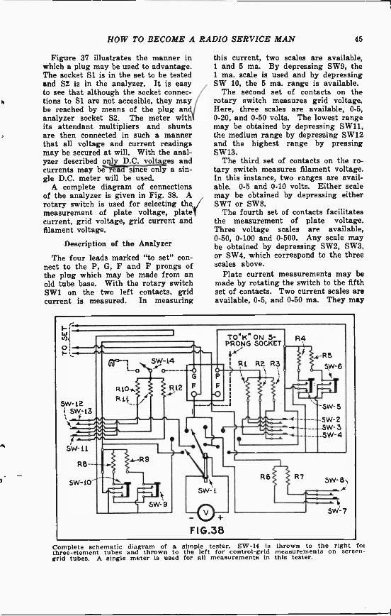
HOW TO BECOME A RADIO SERVICE MAN 45
Figure 37 illustrates the manner inwhich a plug may be used to advantage.The socket S1 is in the set to be testedand S2 is in the analyzer. It is easyto see that although the socket connec-tions to S1 are not accesible, they maybe reached by means of the plug ananalyzer socket S2. The meter withits attendant multipliers and shuntsare then connected in such a mannerthat all voltage and current readingsmay be secured at will. With the anal-yzer described pql_y_p.c. voltages andcurrents may bete since only a sin-gle D.C. meter will be used.
A complete diagram of connectionsof the analyzer is given in Fig. 38. Arotary switch is used for selecting the,/measurement of plate voltage, plateicurrent, grid voltage, grid current andfilament voltage.
Description of the Analyzer
The four leads marked "to set" con-nect to the P, G, F and F prongs ofthe plug which may be made from anold tube base. With the rotary switchSW1 on the two left contacts, gridcurrent is measured. In measuring
this current, two scales are available,1 and 5 ma. By depressing SW9, the1 ma. scale is used and by depressingSW 10, the 5 ma. range is available.
The second set of contacts on therotary switch measures grid voltage.Here, three scales are available, 0-5,0-20, and 0-50 volts. The lowest rangemay be obtained by depressing SW11,the medium range by depressing SW12and the highest range by pressingSW13.
The third set of contacts on the ro-tary switch measures filament voltage.In this instance, two ranges are avail-able. 0-5 and 0-10 volts. Either scalemay be obtained by depressing eitherSW7 or SW8.
The fourth set of contacts facilitatesthe measurement of plate voltage.Three voltage scales are available.0-50, 0-100 and 0-500. Any scale maybe obtained by depressing SW2, SW3,or SW4, which correspond to the threescales above.
Plate current measurements may bemade by rotating the switch to the fifthset of contacts. Two current scales areavailable, 0-5, and 0-50 ma. They may
1-Wi4.04
ol 4.1 IN
SW -12( SW -L3
gr-1 SW -14
R10-*Rlt
SW -11
SW -10
.k --R9
G
R12
SW -9
TOHK" ON 5 -PRONG SOCKET
Ri R2 R3
F
-O--J
R4
0FIG.38
-R5
5W-64(
'SW- 5
- SW -2- -SW-3
-SW-4
R6 R7 SW- 8-
SW- 7
Complete schematic diagram of a simple tester. SW -14 is thrown to the right foithree -element tubes and thrown to the left for control -grid measurements on screen -grid tubes. A single meter Is used for all measurements in this tester.

46 HOW TO BECOME A RADIO SERVICE MAN
be obtained by pressing buttons SW5and SW6.
This analyzer is suitable for batteryoperated receivers where there is noA.C. filament potential to measure, nofive prong tubes, and where nothingbut set analysis is required. For thebeginner it is highly recommended,as it gives a deeper insight into thefunctioning of analyzers than wouldbe obtained by a description of a morecomplicated tester. Its simplicity ofconstruction, low construction cost, andsimplicity of operation should appealto the man who wants to learn by firstgrasping the fundamentals and thenlogically proceeding to the more com-plicated. It is not intended for theman who wants to build "Rome in aday."
Values of PartsOne Jewell 0-.5 ma. meter (internal
resistance 140 ohms);Two 5,000 ohm resistors, R10, R6;One 10,000 ohm resistor, R7;One 20,000 ohm resistor, R11;Two 50,000 ohm resistors, R1, R12;One 100,000 ohm resistor, R2;One 500,000 ohm resistor, R3;
\I One 140 ohm resistor, R9;Two 35 ohm resistors, R8, R4;One 3 ohm resistor, R5;Eight S.P.S.T. push -type switches;Four D.P.S.T. push -type switches;One double pole, 5 point rotaryswitch;Cable, wire, a socket, analyzer plug.
Use of the Simple Set TesteriSuppose, for example, it is desired to
test a simple battery operated receiverof the type depicted in Fig. 26. Thefirst thing that should be done is to
I place the receiver in operating condi-tion by applying normal filament, plateand grid voltages to the set. The plugof the analyzer should be placed in
1 the socket V1 of the set, and the tubeI that originally was in V1 should be
/ placed in the socket of the analyzer.With the rotary switch at the extremeleft, grid current measurements shouldbe made with the 1 ma. scale being used.In all probability no reading will beobtained because the grid current is fartoo small to be measured by such ameter.
The rotary switch should then bemoved to the second set of contacts and
/the 5 -volt scale button depressed. Hereagain a very small reading will be ob-tained because of the presence of thehigh grid -leak resistance R2. If R2be shorted, a reading equal to the valueof the filament voltage will be obtain-ed since the meter in the analyzer isautomatically connected to the nega-tive terminal of the filament and thegrid return lead in the set to the posi-tive terminal. If no reading is obtain-ed, and the condenser Cl is good, thencoil S is open circuited. A reversedreading will be obtained if the "A"battery terminals are reversed.
The measurement of filament vokt-mg is obtained by rotating the switchSW1 (in the tester) to the third set ofcontacts. The value of this voltagemay be made correct (if it is not so)by merely varying the resistance ofRl.
The e,Itagq. may be measuredby rota SW1 to the fourth position.The 0-50 volt scale button should bedepressed since the plate voltage isonly 45 on this tube. Actually it willread slightly less due to the voltagedrop in the primary of the transformerT2. A reading of about 40 volts willusually indicate normal plate voltage.If no voltage reading is secured, it maybe due to an open tickler coil, anopen circuit in the primary of the A.F.transformer T2, lack of proper "B"connections, or a shorted condenser C2.All of the tests necessary to performin order to determine the defective unitwill be described in the following sec-tion.
Plate curre,t may be measured byplacing SW1 in the fifth position. Withthe applied voltage normal, the correctplate current should be obtained. Ifnot, then the tube, in all probability, isdefective and should be replaced. Meth-ods of testing tubes will be describedin a following chapter. The test of thefirst stage is now complete and thesecond is ready to be checked.
The tube from the analyzer is re-placed in the socket of the set and thepositions of the analyzer plug andtube V2 are now interchanged exactlyas in the first case. The same proced-ure is followed but the results will notbe the same as before because of thedifference in the bias and plate voltageapplied.

HOW 2'0 BECOME A RADIO SERVICE MAN 47
When the grid voltage is measured, avery low or a slightly reversed read-ing may be obtained. This is due tothe manner in which the "A" batteryhas been connected in the diagram.The plus of the "C" battery is shownconnected to the plus of the "A" andtherefore the meter in the analyzer isreading the difference between the twovoltages. If the "A" connections arereversed during this reading, a verylarge bias reading will be obtained be-"cause the meter is now reading thesum of the two voltages. This pointshould be carefully borne in mind whentesting battery sets, and the diagramof Fig. 26 was drawn especially to em-phasize this point. The effect of thehigh resistance of the secondary ofthe transformer T2 should also be re-membered when testing this stage.
reads the battery voltage; which is thesame as the full-scale deflection of themeter. If a resistance R is inserted be-tween terminals 1 and 2, the voltmeterreads less than the battery voltage,because of the voltage drop in R, theresistance being measured. The moreresistance between 1 and 2, the lessthe meter reads. This makes it possi-ble to mark or calibrate the scale ofthe voltmeter directly in ohms, so that,when a resistance is connected betweenpoints 1 and 2, the meter reads a cer-tain figure which is the value of theresistance in ohms so connected.
The coil to be tested is connected tofpoints 1 and 2 of the ohmmeter. If themeter reads nothing at all (0), thenthe coil is defective. If the meter doesread, it is difficult to tell whether thecoil is partially shorted or is good, un-
With the voltage and current read-ings obtained, the function of the testeris completed and it remains the prob-lem of the Service Man to interpret Ithe results. No intelligent interpreta-tion is possible without a wiring dia-1gram of the receiver on hand. When/a particular voltage is too low, the'diagram should be consulted immediate4ly. In the testing of Vi (Fig. 26)very low voltage on the plate may beobtained. After deducting the prob-able voltage drop in the primary ofT2, the reading may still be too low toVtobe normal. A test of the battery volt- less the resistance of the coil is known.age and all soldered joints may show ,) For instance, an R.F. transformer isnothing wrong. The man without wound with only a few turns of wire,'diagram would, at this point, be and consequently its resistance is low."stuck" but the one who had foresight An ohmmeter test then, can only indi-to procure the diagram of the receiver icate when the coil is open or closed.before testing it, will immediately see w
that a partially shorted plate bypass On the other hand, a large iron -condenser C2 will cause a considerable cored coil is usually wound with manydrop in voltage and a possible burnout turns of wire and may have a resist -of the primary of T2. ance of several hundred or several
thousand ohms. In this case, theService Man cannot tell the differencebetween a partially -shorted coil and a ,/good one, unless he knows the approx- yimate resistance of the coil when good.This may be usually found in the servicenotes of the radio set, or, if there is asimilar coil in the same or another set,the resistance of one may be comparedwith the resistance of the other. Coilsshould be tested, not only for shortsand open circuits, but Also for a"ground" (sFirriirciifiV.t2, cores.
Testing the CoilsThere are two types of coils used in
radio sets, air -cored and iron -cored.Either type may be open, partiallyshorted or entirely shorted. Now mostanalyzers have, as an integral part ofthe device, a continuity tester or ohm-meter. This is ir-gGing moile-O-r-Tessin its essentials than a voltmeler Vconnected in series with ir-riTdi bat-tery, as shown in Fig. 39. With ter -miners 1 and 2 shorted, the voltmeter
Simple diagram of an ohmmeter.

48 HOW TO BECOME A
In many cases, the cores of chokes,transformers, etc., are grounded to theframe of the set (which is usually atground potential.) The coils themselvesare above ground potential, so that acoil grounded to its core constitutes ashort-circuit.
Fortunately, however, when a coil ina radio set is defective, it usually iseither open or has a dead short; sothat the continuity tester is all that isnecessary to locate defective ones.
Testing the CondensersWhen a Nags= is good it should/
( do tw 'rigs: (1) it should not allowD. . to 2.1p through ' , irFe'ria""r2ritshould therefore accumulate and holda_Aag.e, when its-i-ated llg, volrii:eisl.' d. When a condenser is -leakyi .allows D.C. to pass; so that, to testfor a leak in a condenser, all that isnecessary is to connect the terminalsof the condenser to the ohmmeter. Theneedle of the ohmmeter should move alittle (due to the flow of current intothe condenser necessary to charge itif the capacity is large), and then re-turn to its normal position and staythere. If it does not return to its nor-mal position, but stays somewhere onthe scale, then the condenser is leakyand should be discarded.1 It is perfectly possible for a con-
/ denser to test O.K. on the small volt-age used in the ohmmeter, but breakdown completely when normal voltageis applied. To test a condenser com-pletely, the rated D.C. voltage shouldbe applied for a few moments, and thenremoved. The condenser should be al-lowed to stand charged for a few mo-ments, and then discharged. If a sparkoccurs during discharge, the condenseris good, if there is a weak spark ornone at all, the condenser is defective.
, The above statement applies only to/ condensers of large capacity, about 14
to 1h mf. and larger. For the smallersizes, the continuity test describedabove is sufficient, being enough to de-termine whether the condenser is short-ed or not. It is perfectly possible fora condenser to open, even thorgh it is
RADIO SERVICE MAN
a rare occurrence; an open condensesis one which passes neither D.C. norA.C. Tnis is usually due to brokenor unsoldered leads from the condenserplates to its terminals. To locate anopen in a condenser of small capac-ity is practically impossible. For con-densers of large capacity, the methodsdescribed above for testing condensersmay be used to advantage.
For the electrolytic type of condenser, the rated D.C. voltage may beapplied. A milliammeter connected inseries with the condenser and thesource should read not more than .5ma. per microfarad capacity of theunit. Thus an 8 mf. electrolytic con-denser should have not more than 4.0ma. passing through it, if it is to beconsidered O.K.
It is very useful to be able to measurecondenser capacity. This may be donevery easily by connecting a small cop-per -oxide rectifier in series with a D.C.meter and a source of A.C. potential.The condenser to be measured is alsoconnected in series with the arrange -1ment. The greater the capacity of thecondenser, the greater the reading ofthe meter. In this manner the scale ofthe meter may be calibrated to readdirectly in microfarads, provided thatthe same A.C. source of potential isalways used.
Testing Resistors
Testing resistors really involves (asfar as radio service work is concerned)only the measurement of the value ofthe resistance. If the result of themeasurement is within 10 er ofthe rated value of the um , may beconsidered O.K. If it is far from the,10 percent tolerance, then it should NOdiscarded. Care should be taken, whenreplacing a resistor in a receiver, thatit is able to dissipate the heat fastenough; if it cannot do so, the resistormay burn out due to excessive over-oad.
In the chapter to follow, there wille described complete test equipment
for the more advanced Service Man.

CHAPTER 5
Advanced Service DataEVEN though the equipment de-
scribed in the preceeding chapteris sufficient for the servicing of themore simple battery receivers, it is notcomplete enough for a thorough checkof modern superheterodynes. It issuitable for the embryo Service Manwho feels the necessity of becoming ac-quainted with up-to-date test methodsbut who is not willing to make a largeinvestment in apparatus that he feelshe will not be able to use.
For the Service Man who has hadsufficient experience to recognize theneed for advanced equipment, and forthe beginner who believes that a cer-tain amount of experience will be gain-ed by building modern test equipment,this chapter is dedicated. Completeconstruction details accompany everydescription.
Complete schematic circuit of a simpleR.F. oscillator. All values are markedon the diagram.
The R.F. Oscillator
In the early stages of radio servic-ing, the broadcasting station was usedto conduct all tests. If it so happenedthat no stations were operating at thetime, then it was impossible to conductany tests. During periods of SOS, evenat the present time, it is impossible tointelligently conduct a test on a re-ceiver. Even though a reliable stationis on the air, the continuous change involume that accompanies a selectionthat is being rendered makes the test -
49
ing of receivers unreliable. It is forthe above reasons that an artificialtransmitter (oscillator) should be usedby the Service Man.
The R.F. oscillator is used for thecreation of a signal of any desiredstrength and wave length that is suit-able for the broadcast band i.e., from550 to 1500 kc. A complete schematicdiagram of such an oscillator is shownin Fig. 40.
One of the most important featuresof the oscillator illustrated in the above -mentioned figure is its utter simplicity.It is portable using a '30 type tube, asmall 221/2 -volt battery for plate po-tential and a 2 -cell flashlight "A" bat-tery. The entire arrangement may beplaced in a single carrying case, theinside of which should be thoroughlyshielded to prevent radiation (givingoff energy) from the coil itself. It isdesigned to cover the broadcast bandfrom 550 to 1500 kc. The particularwave length desired may be obtainedby merely rotating the tuning con-denser Cl. The variable grid -resistorR1 is used for the purpose of securingany pitch note desired. While thisfeature may easily be done away with,it is desirable in instances where thefidelity (quality) of the audio ampli-fier in the receiver is to be checked.The output of the oscillator may be ad-justed by varying the arm of the po-tentiometer R2. This adjustment willbe found to be particularly useful whentesting receivers of different sensitiv-ities.
The coil consists of 60 turns of No.20 or 22 silk or double cotton coveredwire wound on a 2 inch diameter formtapped at the center. The coil shouldbe raised a reasonable distance abovethe shield in order to prevent excessiveloss and a consequent loss of efficiency.Under no circumstances should the"B-" terminal be connected to anyof the "A" terminals, for this would

50 HOW TO BECOME A RADIO SERVICE MAN
short circuit the feed back coil andcause the oscillator to stop functioning.An R.F. choke is placed in the platecircuit of the tube in order to keep theradio -frequency power in the oscillatoritself, and not let it wander out intothe "B" battery leads from which radi-ation might take place.
Discussion of CircuitWhile the dynatron oscillator might
be described, it was not for the reasonthat the present type of four elementtubes have their plates blackened soas to reduce secondary emission, theeffect of which is to cause a peculiarbend in the plate voltage-plate cur-rent curve. It is this bend that causesthe tube to oscillate, and since theshape of the bend varies with different
Complete schematic diagram of an I.F.oscillator. Note the similarity betweenthe diagram above and that shown inFig. 40.
tubes, the oscillator is not as stablewith the present type '24 tubes as itwas with the older type tubes.
The oscillator described is a very sta-ble one and the output will not changeappreciably with different tubes, al-though it is a good idea to keep onetube for the oscillator alone.
The oscillator may be marked orcalibrated in the following manner:Tune a radio set to a broadcast sta-tion of known frequency (most news-papers give the frequency of broad-cast stations in the vicinity), and thendisconnect the aerial and ground fromthe set. Start the oscillator by clos-ing the filament switch SW and con-nect the ANT. and GND. posts of theoscillator to the receiver. Then turnthe tuning knob (leaving the tuningof the set constant) until the noteof the oscillator is heard in the loud-speaker. The number on the dial of
the oscillator corresponds to the fre-quency of the broadcast station. Thisoperation is repeated for stations ofdifferent frequencies. A curve is thenplotted, the horizontal lines correspond-ing to the dial setting of the oscilla-tor and the vertical lines to the cor-responding frequency of the broadcast-ing stations. In this manner the fre-quency of the oscillator for any set-ting of its dial may be determined at aglance.
The I. F. OscillatorIn lining up superheterodyne, re-
ceivers, it is desirable, as will be seenlater, to first be sure that all the in-termediate frequency transformers aretuned to their rated frequency. Thismay be accomplished only by a separ-ate oscillator tuned to the intermediatefrequency. Such an oscillator may,of course, be incorporated in the samecase as the R.F. oscillator describedabove.
This has not been done for severalreasons. First, there may be menwho already have R.F. oscillators, butwho contemplate building an I.F. os-cillator-obviously, then, the compositeunit would be undesirable for such men.Second, not all service jobs require theuse of an I.F. oscillator, and consequent-ly. it would increase the weight of theequipment that must be carried if asingle larger unit were described. Third,if certain Service Men feel that theyare not classed under the two catagoriesabove, they may incorporate both os-cillators at will.
Figure 41 shows the schematic dia-gram of an I.F. oscillator that is de-signed for an I.F. of 175 kc. This fre-quency is not made variable becausepractically all broadcast receivers in
use today have their intermediate fre-quency amplifiers tuned to 175 kc.Furthermore, the cost and the size ofthe oscillator is reduced by keeping theoscillator tuned to a constant frequency.
As may be seen from the diagram.the fundamental circuit is exactly thesame as the R.F. oscillator; the onlydifference being in the sizes of thetuning coil and condenser. The con-denser is shown fixed, but it mightwell be variable, or else may be madeto consist of a fixed capacity of .00075mfd. And a small variable condenser of

HOW TO BECOME A R
.00025 mfd. connected across it. In thismanner, the frequency of the oscilla-tor may be varied slightly to compen-sate for discrepancies in circuit con-stants. As may be readily seen, theR.F. and I.F. oscillators may be corn -
Switching arrangement showing how asingle tube may be used for the twooscillators.
bined in a single unit; the change fromone frequency range to the other beingeffected by means of a switch as shownin Fig. 42. The method of using theoscillator will be fully described later.
The Audio OscillatorThe possession of an audio oscillator
seems to be the ambition of a greatmany Service Men. Why they do notpossess one is beyond the comprehen-sion of the author, since many interest-ing experiments and tests may be madewith one. The diagram of connectionsis exactly the same as that of Fig. 41with the following changes:
Coils LI and L2 are the secondaryand primary, respectively, of an ordin-ary low -ratio audio transformer, thegrid leak R1 should be made variablefrom 0 to 10 megs., the choke R.F.C.should be increased to 15 henries, R2should be increased to 500,000 ohms,and the bypass condenser C3 should bechanged to 2 mfd. Variation of the audiofrequency pitch is secured by merelyvarying the size of the grid leak. Al-most any range of audio frequency maybe secured by changing the size ofeither C2 or R1, the greater either oneis made, the lower the frequency gen-erated.
The Output MeterFor frequencies above 100 cycles, the
ordinary A.C. meter is useless. Forthis reason, there have recently beenplaced upon the market small, dry rec-
ADIO SERVICE MAN 51
tifiers that are capable of handlingvery small currents efficiently. Severalof these may be obtained and connect-ed in a bridge arrangement as shown inFig. 43. The resistance R is adjusteduntil the meter reads full scale witha loud signal impressed. In most casesit has a value of 5,000 ohms.
Many manufacturers make their drydisc rectifiers available ready for abridge connection. In such cases, themeter should be connected as shown inFig. 44. The meter M is a D.C. mil-liammeter. The advantage of thismethod of connection lies in the factthat if the arrangement is to be usedfor reading current, the resistor R isshort circuited and the terminals areconnected in series with the circuitthrough which the current is to bemeasured. This instrument can be putto many uses as will be seen later.
The Regenerative ReceiverThe circuit discussed in Fig. 26 is
called a regenerative receiver for thesimple reason that part of the energyin the plate circuit is fed back to thegrid circuit via a coil (called thetickler). The energy so fed back addsto the signal being received with theresult that the strength of the outputincreases as the energy fed back in-creases. A limiting point is reachedwhen the energy fed back becomes sogreat that the tube begins to oscillate(acts as a transmitter); when this oc-curs, the signal is weak and distorted.The object, then, is to adjust the coup-ling between the tickler and the sec-ondary of the R.F. transformer untilmaximum strength is received-if thecoupling be advanced beyond this point,the tube will break into oscillation. Thisvalue of coupling is very critical, and
Left, Bridge connections of a dry rectifier.Right, Internal connections of the rectifier.

52 HOW TO BECOME A RADIO SERVICE MAN
therefore the tuning of such receiversmust be done with some dexterity. Theeffort is compensated by the additionalgain that is secured-about equal toone stage of well designed R.F.
When tuning such a receiver, thetickler should be advanced until the re-ceiver oscillates. The tuning dial shouldbe rotated until a squeal is heard; thisindicates the presence of a broadcaststation. The coupling should be loos-ened a little and the tuning dial re-tuned until the station is loudest, al-though it still may be distorted. Thecoupling is again loosened and the dialagain retuned. This process is repeateduntil a point is reached where the sta-tion comes in loud and clear-until theset just stops oscillating.
Because the tuning of the set is af-fected by changes in the position of thetickler (because of the change in coup-ling), receivers employing regenerativedetectors cannot have their tuningcondensers ganged. This point is adecided disadvantage-in fact, it is forthis reason that present-day receiversdo not employ regeneration.
FIG.45 FIG.46
Two methods of controlling oscillations.
An advantage of the regenerativereceiver is the fact that since the feedback tends or has the same effect asdecreasing the resistance of the tunedcircuit, it tunes sharper than a receivernot employing such feed back. How-ever, this does not mean that it willdiscriminate between stations to agreater extent than other types of re-ceivers; for it must be remembered thatit is only sharp on the particular fre-quency to which it is tuned, and on noother.
A careful Service Man would requirebut a small amount of practice in orderto fully appreciate the advantages tobe gained by the use of regeneration.For short-wave work (in receivers
that are not superheterodynes) it isused to the exclusion of all others.
The Tuned R.F. ReceiverRadio frequency amplification, as is
well known, increases the sensitivity ofa receiver, while audio amplificationincreases the volume output. For reas-onable distant reception, then, a cer-tain amount of R.F. gain is desirable.The amount of amplification per stage(when three -element tubes are used)cannot be increased above a certainamount because energy is fed back fromthe plate circuit to the grid circuit viathe internal capacity of the tube. Asin the regenerative receiver, when thisenergy is great enough, the tube breaksinto oscillation. To obtain a reason-able amount of gain, means must beadopted to minimize the effect of thefeed back.
One of the earliest methods was toplace a 400 ohm potentiometer acrossthe filament terminals and connect thegrid return to the arm of the poten-tiometer as shown in Fig. 45. Whenthe arm was near the positive terminalof the filament, the resistance (grid tofilament) of the tube decreased to suchan extent that a great deal of the en-ergy fed back was dissipated in thisresistance; thus the tube ceased to os-cillate. Rotating the arm toward thenegative terminal increased the resist-ance and consequently the sensitivityof the receiver until it started to os-cillate. In this manner, a control ofthe sensitivity and of the volume wassecured. This method had to be dis-carded when amplifier design calledfor the insertion of a "C" battery, andwhen tubes were made with very highvacuums which increased the grid -fila-ment resistance of the tube to such anextent that a reasonable control of os-cillation could not be obtained.
A second method used to control os-cillation, and one which is still in ex-istence in some receivers, is to place aresistance in series with the tuned cir-cuit and the grid as shown in Fig. 46.This resistance is usually made 800ohms, which value does not detractfrom the sensitivity to a marked de-gree. No manual control is necessary,and, which is far more important, itfunctions independently of the fre-quency to which the set is tuned.

HOW TO BECOME A RADIO SERVICE MAN 63
In view of the fact that feed back iscaused by the grid -filament capacity ofthe tube, a receiver tends to oscillatemore on the shorter waves (higher fre-quencies) than on the longer ones.This means that such a receiver ismore sensitive on the shorter wavesthan on the longer ones, engineers havetherefore taken means to equalize theresponse over the entire broadcastband. With the methods of controllingoscillation shown in Figs. 45 and 46,the position of the arm (in Fig. 45)had to be changed every time the re-ceiver was tuned, and, in Fig. 46, theresponse on the higher wave lengthswas decreased because of the presenceof the resistor, since it was not usuallyrequired at the higher wave lengths.For the above reasons a system of neu-tralization was invented which obviatedboth of the methods described.
The Neutrodyne
In the neutrodyne method of bal-ancing out the feed back, a small con-denser C2 (Fig. 47) connects from thegrid of the tube to be neutralized to atap on the secondary of the transformerof the succeeding tube. Part of theenergy in the grid circuit (the signal)flows through the small capacity C2 tothe small coil L2, which, as stated be-fore is part of the secondary of theR.F. transformer. The remainder ofthe signal is amplified by the tube andappears across Ll. The two coils, Lland L2, being coupled, neutralize oneanother, so that the effect of the feedback is nil.
In neutralizing a receiver (whetherit be an I.F. or aa R.F. stage) one ofthe filament prongs of the tube usedin the stage being neutralized is cutso that the tube does not light (aburned -out tube cannot be used). Asignal is tuned in, which will be heardbecause of the capacity of the tube, andthen the neutralizing condenser C2(which is about 50 mmf.) is adjustedslowly until the signal cannot be heard.The tuning of the set is again adjusteduntil the signal is heard and again it isbalanced out. This is continued untilthe signal is completely balanced out.It may so happen that the signal can-not be balanced out completely; inwhich case the balancing condensers
are adjusted for a minimum response.This procedure is followed for all thestages in the amplifier, the process be-ing repeated at least twice.
Diagram showing the connections of theneutralizing condenser C2.
Another method of neutralization isthe so-called Rice method. The methodof connection is illustrated in Fig. 48.The theory underlying this method issimpler than for the one outlined above.The tuning coil L is tapped in the ex-act center as shown. Energy is fedfrom the plate to the grid via the in-ternal capacity of the tube CL Nowsince the coil is tapped in the exact cen-ter, the capacity of C2, the balancingcondenser, is made equal to the capacityCl, by balancing the stage just as forthe neutrodyne method described above.When this condition exists, the voltageinduced in Ll due to the capacity of thetube is equal to that induced in it bycoil L2, which derives its energy fromthe plate circuit via C2.
Because a symmetrical arrangementof coils and condensers are used in theRice method, the setting of C2 is,theoretically at least, independent offrequency. This is not true of the neu-trodyne method since the action dependsupon mutual induction. It is regret-table that space does not permit a morelengthy discourse on this subject.
Diagram illustrating the Rice method ofbalancing.
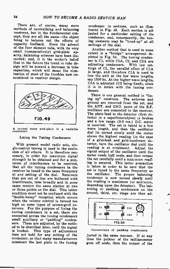
54 HOW TO BECOME A
There are, of course, many moremethods of neutralizing and balancingreceivers, but in the fundamental con-cept, they are all the same-the objectbeing to balance out the effects ofcapacity feedback. Since the adventof the four element tube, with its verysmall (comparatively) grid -plate ap-acity, balancing schemes have been dis-carded; and, it is the writer's beliefthat in the future the trend in tube de-sign will be toward a decrease in tubecapacities, which will mean the elim-ination of most of the troubles now en-countered in receiver design.
A typical rotor end -plate in a variablecondenser.
Lining the Tuning Condensers
With present model radio sets, sin-gle -control tuning is used to the exclu-sion of all others. It is therefore nec-essary, in order for maximum signalstrength to be obtained and for a min-imum of interference to be received,that all the tuning condensers in thereceiver be tuned to the same frequencyat any setting of the dial. Receiversthat are out of line are bothered withinterference, tune broadly and in somecases receive the same station at twoor three points on the dial. This lattercondition must not be confused with the"double -hump" reception which occurswhen the volume control is turned toohigh on some types of screen -grid re-ceivers. For the purpose of lining thetuning condensers in a set, there areconnected across the tuning condenserssmall auxiliary or "padding" conden-sers. These are adjusted, by the meth-od to be described later, until the signalis loudest. This type of adjustmentdoes not hold for any setting of thecondenser, so that many manufacturersconstruct the last plate in the tuning
RADIO SERVICE MAN
condenser in sections, such as illus-trated in Fig. 49. Each section is ad-justed for a particular setting of thecondenser, and, consequently, the tun-ing elements may be "lined -up" at allsettings of the dial.
Another method that is used to someextent is a "bridge" arrangement de-picted in Fig. 50. The tuning conden-ser is Cl, while CIA, C2, and C2A areadjusting condensers. With low set-tings of Cl, the parallel effect of CIAis large, and therefore CIA is used toline the unit at the low wave lengths,say 1500 kc. At the higher wave lengths,C2A is adjusted (C2 being fixed), sinceit is in series with the tuning con-denser.
There is one general method in "lin-ing up" receivers. The antenna andground are removed from the set, andthe ANT. and GND. posts of the R.F.oscillator are connected to the receiver.The plate lead to the detector (first de-tector in a superheterodyne) is brokenand a low range (0-2 ma.) D.C. meteris inserted. The set is tuned to a lowwave length, and then the oscillatordial its turned slowly until the metershows the highest reading (in the caseof a grid -leak and grid -condenser de-tector, turn the oscillator dial until thereading is at minimum). Adjust thesignal output of the oscillator until themeter reads half scale, and then retunethe set carefully until a maximum read"-ing is secured. This latter precautioni3 taken in order to be sure that theset is tuned to the same frequency asthe oscillator. The proper balancingcondenser is now turned slowly untilthe reading is maximum (or minimum,depending upon the detector). The bal-ancing or padding condensers on thesecond, third, etc. stage are then ad -
CL CLA
Ca C2A
FIG.50
Connections of padding condensers.
justed in the same manner. If at anytime the pointer of the milliammetergoes off scale, then the output of the

HOW TO BECOME A RADIO SERVICE MAN 66
oscillator should be reduced. This pro-cedure should be gone over at leasttwice in order to secure satisfactory re-sults. The dial of the set should nowbe tuned to the high wave bands andexactly the same routine followed. Incases where only one padding condenserin each R.F. stage is present, only onewave -length adjustment is possible, andthe dial of the set should be tuned tothe middle of the scale and the balanc-ing done there.
Circuit showing the connections of a typi-cal full -wave rectifier and filter system.
If it is inconvenient to break theplate lead, an analyzer may be used,the lowest scale on the meter beingused. If the Service Man is in posses-sion of an output meter, then it may beconnected across the primary of theoutput transformer, and used in exactlythe same manner as the milliammeterdescribed above.
The Power Unit
The power unit of any receiver con-sists essentially of a power transform-er, a rectifier tube, two chokes, threefilter condensers, and a bleeder resistor,as indicated in Fig. 51. Several tapsmay be taken from the resistor asshown. Suppose that trouble is sus-pected in the power unit. How shouldone test it? The defects may be out-lined in the following manner:RI Shorted
Set not connected to power unit, novoltage between 0 and 1; all othervoltages higher than normal with setconnected or not connected to powerunit.RI Open
Set connected, voltage from 0 to 1,higher than normal; set disconnected
from power unit; voltage from 0 to 1,very high; 0-2, high; 0-3, high.R2 Shorted
Set connected, voltage between 1 and2 zero; set disconnected from powerunit; voltage between 1 and 2, zero;all other voltages high.R2 Open
Set connected, voltage between points1 and 2 high; set disconnected frompower unit, voltage between points 1and 2, very high; 0-1, zero; 0-2, high;0-3, high.R3 Shorted
Set connected, voltage between 2 and3 zero, all other voltages high; set dis-connected from power unit; voltage be-tween 2 and 3, zero; all other voltageshigh.R3 Open
Set connected, voltage between 2 and3 high; set disconnected from powerunit; voltage between 2 and 3, high;voltage from 0-1, zero; from 0-2, zero;from 0-3, high.C3 Shorted
No voltage in set, CH.1 and CH.2 hot,rectifier tube red, transformer hot.C2 Shorted
No voltage in set, CH.1 hot, CH.2cool, rectifier tube red, transformer hot.Cl Shorted
No voltage in set, CH.1 and CH.2cool, rectifier tube very hot, transformervery hot.CH.1 or CH.2 Partially Shorted
Voltages in receiver high, A.C. humapparent.CH.1 or CH.2 Grounded
Symptoms the same as for when C2or C3 is shorted.
The effect of an open power trans-former is simply a lack of voltage onthe rectifier tube. A partially shortedsecondary is noticed by a hum in thereceiver; hot transformer, especiallysurrounding the section that is shorted;and reduced output voltage.
Superheterodyne Receivers
Because of the fact that R.F. ampli-fliers break into uncontrollable oscilla-tion when too much gain is attempted,mainly because of inter -electrode cap-acity, a very ingenious scheme has beeninvented that minimizes the tendencyto oscillate. Since the feed backthrough a tube diminishes as the fre-

66 HOW TO BECOME A RADIO SERVICE MAN
quency is lowered, Major Armstrongsuggested the idea of having a local os-cillator in a receiver that will reactwith the incoming signal in such a man-ner that the resultant signal is reducedin frequency. This new signal maynow be amplified in the usual manner,and, because of the diminished fre-quency at which amplification is nowtaking place, the amount of amplifica-tion that may be obtained in an ampli-fier without oscillation can be increased.
It is clear, then, that in order for aresultant low frequency to be gener-ated, the frequency of the local oscilla-tor must differ from that of the de-sired signal by an amount equal to thelow -frequency at which amplificationis to take place. This low frequency iscalled the intermediate frequency andis abbreviated I.F. A distinct advan-tage of such a receiver is the fact thatthe intermediate frequency may be keptthe same regardless of tuning of the setover the broadest band, and consequent-ly no tuning condensers are required inthe 1.F. amplifier stages. In this man-ner the number of tuned elements maybe reduced to a minimum although thenumber of pre -detector stages of am-plification is large.
A general description of the modernsuperheterodyne is as follows: A sig-nal is received by the antenna and am-plified by one or two stages of R.F.amplification. An oscillator, having itstuning condenser on the same shaft asthe R.F. tuning condensers, generatesa voltage at a frequency differing fromthe signal frequency by the I.F., whichin modern receivers is 175 kc. In thegrid circuit of the tube following theR.F. amplifier, which is called the mix-er, demodulator, or first detector, theoscillator voltage is connected in ser-ies with the signal voltage, and the re-sultant voltage actuates the tube. Nowthis tube must be used as a detectorin order that the signal that appears inthe plate circuit be the difference be-tween the two-hence the name, firstdetector. The signal is now amplifiedby two or three stages of I.F., recti-fied by a second detector, and then fedto the audio amplifier.
From the above brief description,several important facts present them-selves, which are as follows:
(1) How may the I.F. transformersbe adjusted to their rated intermediatefrequency?
(2) How may the oscillator be ad-justed so that the difference frequencyis always constant, i.e., 175 kc.
(3) What procedure should be fol-lowed in lining up a "super"?
Without entering into a lengthytechnical description of why a certainprocedure is necessary, let it be statedthat first it is imperative that the I.F.transformers be lined by means of aseparate oscillator; second, the R.F.tuning condensers lined, and third, theoscillator condenser adjusted.
How to Line the I.F. StagesFirst, remove the oscillator and all
the R.F. tubes from their sockets, leav-ing only the first detector, the I.F., thesecond detector, and, if desired, theaudio amplifier tubes in their sockets.Connect the two terminals of theseparate I.F. oscillator to the grid andcathode terminals of the first detector,after first disconnecting the secondaryof the R.F. transformer of the first de-tector tube. A milliammeter is nextconnected in series with the plate ofthe second detector, or an output metermay be connected across the terminalsof the output transformer as previous-ly described under "Lining up the R.F.Stages."
The oscillator is then tuned to 175 kc.and the "trimmer" condensers are tun-ed on each of the I.F. transformers inturn, until the reading of the meter isa maximum (or a minimum if a grid -leak and grid -condenser detector isused). This process should be repeat-ed at least twice in order to insure ac-curacy. In cases where it is inconven-ient to remove the secondary of thetransformer feeding the first detector,the two terminals of the oscillator maybe connected to a small coil of aboutfive turns, and this coil coupled closelyto the grid coil of the first detector.
With the I.F. transformers correctlylined, the tubes may break into oscilla-tion (even at 175 kc., especially ifthree -element tubes are used). Thenext procedure is to neutralize eachstage in the same manner as describedfor R.F. stages; and, when this is com-pleted the lining -up process should berepeated. The entire routine may have

HOW TO BECOME A
to be gone over several times beforethe amplifier is acting normal, but theeffort will be compensated by the verystable results secured.
Lining the Oscillator CondenserWith the I.F. units in line, the next
procedure is to adjust the R.F. tuningcondensers; which is accomplished inthe manner previously described. It isapparent that when the I.F. units andthe R.F. condensers are in line, max-imum signal strength will be obtainedwhen the oscillator frequency is sep-arated from the signal frequency byexactly 175 kc.
Now this intermediate frequency of175 kc. may be obtained either with theoscillator 175 kc. above or below thesignal frequency. Modern practice dic-tates that it shall be tuned above thesignal frequency in order to minimizeinterference.
Our milliammeter is again connectedin the plate circuit of the second de-tector, all the tubes in the receiver areinserted, and the R.F. oscillator termin-als connected to the ANT. and GND.posts of the receiver in the usual man-ner. The receiver is tuned to a lowwave length, the oscillator tuning con-denser is loosened from its shaft andslowly rotated until maximum responseon the meter is noted. The R.F. tun-ing condensers are then rotated slowlyto determine if there is any increase inresponse, and should be left at the max-imum point. It might be wise to tunecarefully the external oscillator at thistime to be sure of a maximum deflec-tion of the meter.
The oscillator condenser in the re-ceiver is turned very slowly for maxi-mum response. Two points on this con-denser will be found. Choose the onewith the minimum meshing of conden-ser plates. The same procedure is fol-lowed for a higher wave length.
The receiver is now "lined up" and"ready to go".
The Audio AmplifierThe methods to be followed in ser-
vicing an audio amplifier are exactlythe same as for the R.F. amplifier here-tofore described. The fundamentalpurpose of such an amplifier is to in-crease the strength of the signal afterit is rectified. It does not increase thesensitivity of a receiver-as many peo-
RADIO SERVICE MAN 57
pie are lead to believe. Just because aset has enormous volume, does not meanthat it can receive distant stations.The amount of amplification that maybe desired is limited by two factors;the size of the room and the noise level.The latter factor is controllable onlyby very careful design, which is be-yond the scope of this book.
9
6ti
;:
O 30 2
1 2 3 4 5 6 7 6 9 10POSIT ON OF OSCILLATOR SETTING
FIG.52
Response curve of an audio amplifier.
An interesting experiment thatthe experimenter or Service Manmay perform is to compare thequality of output of different am-plifiers. All the apparatus that is re-quired is an audio oscillator, suchdescribed in this chapter, and two out-put meters. The output of the audiooscillator is connected across the prim-ary of the first A.F. transformer; allthe tubes may be left in their socketsif so desired. One output meter is con-nected directly across the output of theoscillator and the other is connectedacross the voice coil of the speaker oracross the primary of the output trans-former.
The oscillator is adjusted for a lownote, the lowest possible, and the read-ing of the first output meter noted.The volume control on the oscillatorshould now be adjusted for a conven-ient reading with a reasonable responsefrom the speaker. The reading of thesecond output meter is noted and jotteddown on a piece of paper. The pitchor frequency of the oscillator is raiseda little, and the volume control adjust-ed until the reading of the first out-put meter is exactly the same as be-fore; the reading of the second outputmeter is again noted. This procedureshould be followed until the entireaudio frequency has been covered-say from 50 to 5000 cycles per second.
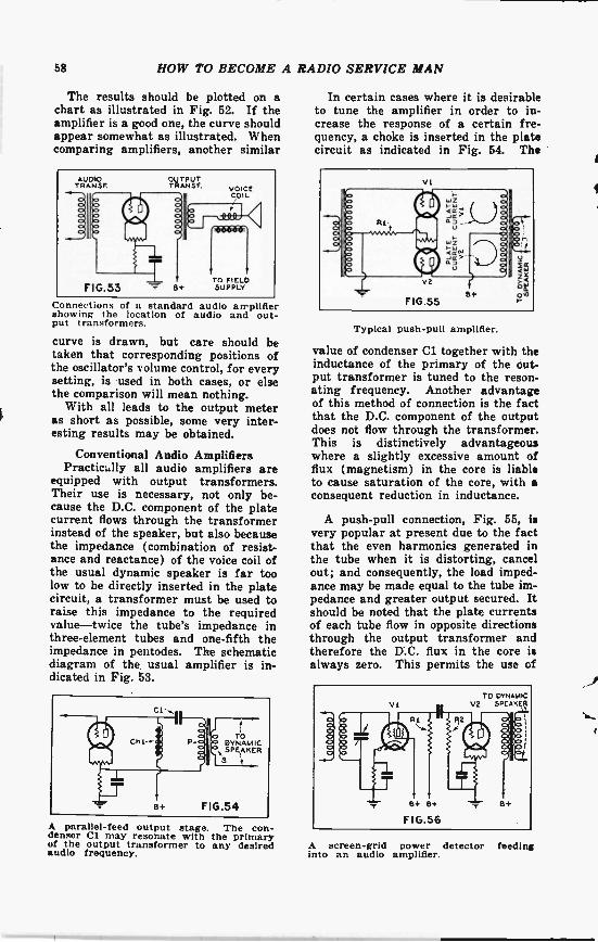
58 HOW TO BECOME A RADIO SERVICE MAN
The results should be plotted on achart as illustrated in Fig. 52. If theamplifier is a good one, the curve shouldappear somewhat as illustrated. Whencomparing amplifiers, another similar
Connections of a s andard audio amplifiershowing the location of audio and out-put transformers.
curve is drawn, but care should betaken that corresponding positions ofthe oscillator's volume control, for everysetting, is used in both cases, or elsethe comparison will mean nothing.
With all leads to the output meteras short as possible, some very inter-esting results may be obtained.
Conventional Audio AmplifiersPractically all audio amplifiers are
equipped with output transformers.Their use is necessary, not only be-cause the D.C. component of the platecurrent flows through the transformerinstead of the speaker, but also becausethe impedance (combination of resist-ance and reactance) of the voice coil ofthe usual dynamic speaker is far toolow to be directly inserted in the platecircuit, a transformer must be used toraise this impedance to the requiredvalue-twice the tube's impedance inthree -element tubes and one -fifth theimpedance in pentodes. The schematicdiagram of the. usual amplifier is in-dicated in Fig. 53.
A parallel -feed output stage. The con-denser Cl may resonate with the primaryof the output transformer to any desiredaudio frequency.
In certain cases where it is desirableto tune the amplifier in order to in-crease the response of a certain fre-quency, a choke is inserted in the platecircuit as indicated in Fig. 54. The
Typical push-pull amplifier.
value of condenser Cl together with theinductance of the primary of the out-put transformer is tuned to the reson-ating frequency. Another advantageof this method of connection is the factthat the D.C. component of the outputdoes not flow through the transformer.This is distinctively advantageouswhere a slightly excessive amount offlux (magnetism) in the core is liableto cause saturation of the core, with aconsequent reduction in inductance.
A push-pull connection, Fig. 55, isvery popular at present due to the factthat the even harmonics generated inthe tube when it is distorting, cancelout; and consequently, the load imped-ance may be made equal to the tube im-pedance and greater output secured. Itshould be noted that the plate currentsof each tube flow in opposite directionsthrough the output transformer andtherefore the D.C. flux in the core isalways zero. This permits the use of
A screen -grid power detector feedinginto an audio amplifier.

HOW TO BECOME A RADIO SERVICE MAN 69
a better grade of iron than is possiblewhen D.C. flux is present. Another im-portant feature is the fact that there isno bypass condenser necessary acrossthe "C" bias resistor. An elementaryexamination of the theory of this typeof amplifier will show that when theplate current of one tube is increasing,then the plate current of the other isdecreasing by the same amount and atthe same rate; the net current throughthe resistor at all times being constant;no bypass condenser is therefore neces-sary.
Detectors
In some types of receivers the out-put of a linear detector feeds directlyinto the power tube as shown in Fig. 56.This is a resistance -coupled stage andis used only when a screen -grid tube is
Connections of a two -element detector.Note the similarity between this and thehalf -wave rectifier used in the powerunitthe detector. It is more economical touse a coupling transformer when athree -element tube is the detector be-cause of the additional gain that is se-cured. The remainder of the circuit isself-explanatory.
The old adage "History repeats it-self", seems to hold true in radio aswell as in the academic subjects. In1914, before the broadcast era, two ele-ment detectors were being used. Nowin 1932 they have come into vogue asthe latest in receiver design. The sim-ple schematic circuit is illustrated inFig. 57. A three -element tube with itsgrid and plate connected together isused as the detector. Note the lack ofplate voltage and the unique method ofconnection.
Its brother, the Duo -Diode has justbeen introduced at this writing. Theschematic circuit is depicted in Fig. 58.
It is simply a full -wave rectifier simi-lar to the '80 type used in the powerunit.
With the brief description of theabove types of detectors, the questionnaturally arises as to why they areused. When radio was in its earlystages, the factor of sensitivity wasgreater than any other. Engineerswere at work constantly to developmore sensitive receivers, and they sure-ly have accomplished their purpose.With the sensitivity problem settled,they turned their attention to quality,and no one will deny the fact that re-markable strides have been made alongthis direction recently.
One of the contributions to this im-provement in quality was the elimina-tion of one of the audio stages. The
The duo -diode detector-a full wave rec-tifier.
more amplification in the audio end ofthe receiver, the greater the distortion.Since present receivers have sufficientgain in the R.F. stages for all practicalpurposes, and since the "linear" detec-tor is capable of handling this largevoltage, there is no need for two stagesof audio amplification.
The diode and Duo -Diode detectorsare capable of handling far more volt-age without distortion than any othertype, and therefore are used in verysensitive receivers. For very weak sig-nals they are worthless. However, mod-ern receivers have sufficient gain to ob-viate the latter difficulty.
THE ANALYZERFigure 38 depicted an analyzer that
was suitable for testing 4 -prong tubes.In view of the rather extensive use ofof 5 -prong tubes, it was thought advis-

60 HOW TO BECOME A RADIO SERVICE MAN
4 -PRONG 5 -PRONGSOCK ET SOCKET
FIG.59The five -prong socket on the right con-nects to the four -prong socket as shownin order to test heater -type tubes.able to include an additional socket fortesting these tubes. At the same time,additional connections may be added inorder to test screen -grid tubes. Fig. 59shows the diagram of connections of theadditional fifth socket.
As may easily be seen by referenceto the diagram, the "heater" prongs ofthe 5 -prong socket are connected di-rectly to the "filament" prongs of the4 -prong socket. The grid and plateconnections are connected together asshown. Note that the "K" (cathode)connection remains unconnected. It goesdirectly to the switch as shown in Fig.38.
Since the plug of the analyzer hasbut four prongs, an adapter must beused when 5 -prong tubes are to betested. It is desirable to change theanalyzer cable for a 5 -wire type; theconnections being indicated in Fig. 60.With this new cable, a 4 -prong adaptermust be used when testing 4 -prongtubes.
For testing screen -grid tubes, a sixthwire must be added to the cable, as
Analyzer cable used for testing screen -grid tubes. The cable leads are markedand correspond to the socket markingsalso given.
ANAL' ZERCABLE TO5 -PRONGSOCKET
Adapter and cable used for testingheater -type tubes. Also see Fig. 61 be-low. The adapter used in both figures Isthe same.
shown in Fig. 61. This cable may beadded to the five -wire cable describedabove, if desired. The adapter fortesting 4 -prong tubes is the same asshown in Fig. 60. The only change be-tween the cable of Fig. 60 and that ofFig. 61 is the addition of another wireconnected to caps designed to fit theplug on the top of the tube.
Since screen -grid tubes are beingtested, means must be provided tomeasure the screen -grid voltage andcurrent. The additional contacts neces-sary are indicated in Fig. 62. A 50,000 -ohm resistance has been added in orderto increase the range of the meter. Therotary switch, SW.1 in Fig. 38, usuallyhas more than the required amount ofcontacts, so that the additional changemay easily be made.
For the measurement of screen -gridcurrent, SW14 in Fig. 38, is thrown tothe left. This connects the grid multi-pliers and shunts to the screen -grid ofthe tube as shown, which also connectsto the screen -grid wire leading fromthe cable as shown in Fig. 61.
PRESENTSET
A
50.000OHMS
vses)Lvsi.Ns
o o 0 0
SET OF CONTACTS NOWADDED FOR SCREEN-
GRID VOLTAGE TESTS
FIG.62Additional set of contacts used for =rein -grid voltage tests.

about thisManual:
Norfolk, Va.I received the OM,
DIAL RADIO SERVICEMANUALS ordered as
per my letter of March25, 1935 in good order.
I am very well pleasedwith same as it is a veryvaluable Radio Servicedata reference and guide.
Arthur J. Freeney.
Detroit, Mich.Received your 1935
OFFICIAL RADIO SER.VICE MANUAL andcertainly is something torave about. It's great.
A. Hedke.
Stillwater, MaineI have received the
1735 Manual, and I am
very much pleased withmy investment.
Franklin J. Holtnes.
Swift Current,Saskatchewan. Canada.
I beg to acknowledgereceipt of my 1935 issueof the OFFICIAL RADIOSERVICE MANUAL.
Your Manual is fine,and would not be withceit any of them. TheManuals may be improvedfor Canadian use.
A. M. Ford.
--for the realservicing "dope"
you can't find abetter book!
NO other radio book is comparableto the 1935 OFFICIAL
RADIO SERVICE MANUAL. Incontents, in style of printing, ingrade of paper, in illustrations, therehas never been published such a com-prehensive volume.
The 1935 Manual contains over athousand pages-yet ,it is only 1/4
inches thick because it is printed ona special Bible stock which is an ex-ceptionally good stock, yet one of thethinnest and most durable papers.This 1935 Manual is the most au-thentic and elaborate service guideever used in the radio industryService Men and dealers who use this
What Others Say 1935 Manual are astonished by finding in it such a wealthof profitable service information which has never beenpublished before.
Contents of the 1935 ManualOver 1,000 pages full of diagrams and essential informa-tion of manufactured receivers-only data of real use inservicing is included. This new Manual is really portablesince it will be extremely thin and light as well. VolumeV continues where the preceding manual left off. Manycircuits of old sets are included. Service Men knowevery set has certain weak points which are really thecause of trouble. Wherever the information could beobtained, these weaknesses with their cures are printedright with the circuits. This is an entirely new and valu-able addition to the Manual. All the latest receivers areincluded-all-wave sets, short-wave sets, auto -radio sets,midget and cigar -box sets, etc., as well as P.A. amplifiersand equipment, and commercial servicing instruments. The cumulative index is even more complete than be-fore: including cross-reference to sets sold under differentnames and type numbers. Volume V includes resistancedata: socket layout; I.F. data: and voltage data. Tubedata on latest tubes. Free question and answer servic.-as included in our last three manuals.
OVER 1,000 PAGESOver 3,000 Illustrations
Flexible, Looseleaf Leatherette CoversSize 9x12 Yet only 114" thick
Send remittance of $7.00 in forth of check or money order for your copy ofthe 1935 OFFICIAL RADIO SERVICE MANUAL. Register letter if it con-tains cash Or currency. THE MANUAL IS SENT TO YOU POSTAGE PREPAID.
GERNSBACK PUBLICATIONS, Inc.99PR HUDSON STREET NEW YORK N. Y.