Embed Size (px)
Citation preview

UNCLASSIFIED
AD NUMBER
CLASSIFICATION CHANGESTO:FROM:
LIMITATION CHANGESTO:
FROM:
AUTHORITY
THIS PAGE IS UNCLASSIFIED
AD395451
UNCLASSIFIED
CONFIDENTIAL
Approved for public release; distribution isunlimited.
Distribution authorized to U.S. Gov't. agenciesand their contractors;Administrative/Operational Use; DEC 1967. Otherrequests shall be referred to Air Force RocketPropulsion Lab., Edwards AFB, CA.
31 Dec 1979 DoDD 5200.10 ; AFRPL ltr 5 Feb 1986

Wi'pwyii5|TOTWfTVW*™w«cw>Mmw
IHIS R 4 "?
UN
Nu RESTRICTIONS A
ITS
fei
c, { r» iT
APPROVED F08 PUBLIC RilSÄSEj
DI S
—^W-M^MJII irMl^i«[||'im«t««tfTm«MiaiMirii>iMii<ay', 8
——"—' —" ■-■"- aUtBtam —ill
pHB!ilj>B«a^aBuaÄWüaiEJös»ii I i;
0 39C) VU
AUTHORITY:
///I "~5/-eÄ Ki
Ws--"1- ■//■/
V
/ Mi»i.ÄPiii,juTflaiiÄ^j»aLt/iiUHÄ*fi;W*ÜAÜfli^ ̂ ;s^i.^*\V^"mÄ^(&i^4<W'fe*^^

r . ........ -···· -
Best Available
Copy
mm m wtß^imiimmm. vmm
SECURITY IMMii
The classified or limited status of this report applies to each page, unless otherwise marked. Separate page printouts MUST be marked accordingly.
THIS DOCUMENT CONTAINS INFORMATION AFFECTING THE NATIONAL DEFENSE OF THE UNITED STATES WITHIN THE MEANING OF THE ESPIONAGE LAWS, TITLE 18, U.S.C., SECTIONS 793 AND 794. THE TRANSMISSION OR THE REVELATION OF ITS CONTENTS IN ANY MANNER TO AN UNAUTHORIZED PERSON IS PROHIBITED BY LAW.
NOTICE: When government or other drawings, specifications or other data are used for any purpose other than in connection with a defi- nitely related government procurement operation, the U.S. Government thereby incurs no responsibility, nor any obligation whatsoever; and the tact that, the Government may have formulated, furnished, or in any way supplied the said drawings, specifications, or other data is not to be regarded by implication or otherwise as in any manner licensing the holder or any other person or corporation, or conveying any rights or permission to manufacture, use or sell any patented invention that may in any way be related thereto.
^
• .-.., ,■;.:•■; , •.;■.■ . ~. ,.
ja.^imaaaimM^a.MM.aalieil^BJMt^i!^^ irMffiiliiiiil miMMiiiiiimM^^

mm^^WWifWt'W ■ ■ -■ ■ ■"■ ; ■ ■
„■j^^^^p^^p^p-H^^j^-n^n^^
CONFIDENTIAL
AFRPL-TR-68-46 1/
(UNCLASSIFIED)
ADVANCEMENT OF INJECTOR AND THRUST
CHAMBER TECHNOLOGY
■
■
r ;
>- f.l-
CJ> I.I.J „J
G. A. Voorhees, Jr.
TRW Systems Group
TECHNICAL REPORT AFRPL-TR-68-46
DECEMBER 1967
/D D C
i< FE8 14 1969 i 11! rrf-nr-rrr ■, ,
r D
This report contains information covered by a patent secrecy order. See inside front cover for patent secrecy order notice.
GROUP-4
DOWNGRADED AT 3 YEAR INTERVALS; DECLASSIFIED AFTER 12 YEARS
In addition to security requirements which must be met, this document is subject to special export controls and each transmittal to foreign governments or foreign nationals may be made only with prior approval of AFRPL (RPOR-STINFO), Edwards, California 93523,
Thit document contaim information affecting the national defeme of the United States within the meaning of I he Eipionage Lows, Title
18, U.S.C., Section 793 and 794, the tranimiition or revelation of which in any manner to an unauthoiired penon is prohibited by law,
AIR FORCE ROCKET PROPULSION LABORATORY DIRECTORATE OF LABORATORIES
AIR FORCE SYSTEMS COMMAND UNITED STATES AIR FORCE
EDWARDS, CALIFORNIA AF 04(611)-11382 "")-'•
CONFIDENTIAL
■
,
. . ■ ■rV ■^^r■-V^f#te^^t^^^^>!^l-*'~^i'l^.«V..v»V■■^.A äj£i^M&ä^m&
^rtf^^.rr^'^rr^T^^^^r^^ t,'^'r;T"rr"T5rr^:
PATENT SECRECY NOTICE
The subject mattei- in this document contains information which is the subject matter of patent applications on which the United States Patent Office has issued secrecy orders. These secrecy orders are superim- posed on the usual secrecy regulations which are in force with respect to miluary contractors' activities. Information under patent secrecy orders must not be disclosed to unauthorized persons. By statute, violation of a Secrecy Order is punishable by a fine of not to exceed $10, 000 and/or imprisonment for not more than two years.
cfiTi mm SECTION
m mt SKTIM
WIAMOBMai ffQ I'JSTIFICATIM
>r DisTmimnoH/mdMiiiTY COOES
OISI. , AVAIL' «nd or SPECML
When U.S. Government drawings, s pec ii'icat. ion s,
or other data are used for any purpose other than a
definitely related Government procurement operation,
the Government thereby incurs no responsibility nor
any obligation whatsoever, and the fact that the Govern-
ment may have formulated, furnished, or in any way
supplied the said drawings, specifications, or other
data, is not to be regarded by implication or otherwise,
or in any manner licensing the holder or any other
person or corporation, or conveying any rights or
permission to manufacture, use, or sell any patented
invention that may in any way be related thereto. ■
■
teftmaiitai^^«^^ iiiiiiiBti^

igPMjpiaiHppj^^^ ■mmmimm*mmnmimmmmm*'mu>wiiTmm ^■Wtr.,MU.!.J..i.i..l.;j|t.|...,..jjli.H.1....Al,;,l^^.J^,,e^|l^,,w,:.T,^
'•. '-■{ ■■ CONFIDENTIAL
~Kti :, k.} H tc-c
,4) -68-46
(UNCLASSIFIED»
ADVANCEMENT OF INJECTOR AND THRUST
CHAMBER TECHNOLOGY K (A w G. A./Voorhees, Jr
TRW Systems Group
l T C TECHNICAL REPWT >\F RPL-TR-68-46
li_ ( I /J~DECSMaBR 1S67
OHIS^J
M
Total Pages 51
UIJ fiFJ^^iij-iioU
DOWNGRADED AT 3 YEAR INTERVALS; DECLASSIFIED AFTER 12 YEARS
In addition to security requirements which must be met; this document is subject to special export controls and each transmittal to foreign governments or foreign nationals may be made only with prior approval of AFRPL (RPOR-STINFO), Edwards, California 93523,
Thii document conraint informolion aflectino the national defense of the United Statei within the meaning of the Elpionage Lawi, Title
18, U.5.C., Section 793 and 794, the trantmijiion of revelation of which in any manner to an unauthomed person it prohibited by law.
>0fK
..iQ
CONFIDENTIAL
3^y yw*
AF 04(611)-11382
/ V73
/y ^.
aMM^^^amat^^^^-i^ ng^mjuggiteg

•'WJl'» ■l!J.iJll|!|JUiJi...l*M4llU IIWUBlKWIliI aiMl!ap,iiBpiiPi«iiw>My^MwwiJ^p.iBi(^^
UNCLASSIFIED
FOREWORD
/
(U) This final technical/report covers all work performed under Contra,-t AF 04(61 1)-1138Z, Modification No. 3, "Advancement of Injector and Thrust Chamber Technology," dated 21 March 1967. The report was prepared by G. A. Voorhees, Jr., Project Engineer, Chemical Propulsion Technology Department. The test program was monitored by the Air Force Rocket Propulsion Laboratory (AFRPL), Edwards, California (T. Chew, Project Engineer).
(U) This report contains results of a program of engine test firings of a centrally located, coaxial injector, rated at 250, 000 Ib^ thrust, in the throttled condition at the 50, 000 lbf thrust level,
(U) Publication of this report does not constitute Air Force approval of the report's findings or conclusions. It is published only for the ex- change and stimulation of idea.s.
T. J, C. CHEW Chief, Combustion Technology Section Liquid Rocket Division Air Force Rocket Propulsion Laboratory
«BJSSIF1ED u
^■""'"^ffllffllltfill mmm TT r; ■ i--itiriJiiiiifiliiiilg|flliii'i tm •■^^"'^^^»itliriiiilWIiiiiifll

ppBjBppiiWWB^MIWW'W'1^^
(g@OT©gKnim SUMAdARY
(U) An experimental test program to determine the scalability of the LMDE centrally located, coaxial injector to much higher thrust levels than previously tested has been completed. The experimental program was conducted generally in accordance with paragraphs 2. 5, 2. 6, and 2. 7 of Exhibit "A" Technical Requirements of the aforementioned contract.
(U) The design of a nominal 250, 000 lb thrust, 300 psia chamber pressure Thrust Chamber Assembly (TCA) capable of operating at a reduced thrust level of approximately 50, 000 lb thrust was accomplished and fab- rication using commerc.al, industrial fabrication techniques for the less critical components without precision tolerances was successful. The fCA design consisted of a centrally located coaxial injector and heat sink combustion chamber. The VETS B-l test stand at Capistrano Test Site was modified to accept the TCA for firing tests.
(C) Fifteen test fi"ings using N^O./UDMH and totaling approximately 80 seconds of firing time were made during the test program. The influence of momentum ratio and mixture ratio on combustion efficiency (C*) of the centrally located coaxial injector was explored for two injector configurations. The initial test series (six firings) resulted in performance levels of 85 per- cent varying from a low of 82. 5 percent at an, oxidizer/fuel (O/F) ratio of 2. 26 to a high of 85. 5 percent at an O/F ratio of 2. 76. The second test series (six firings) utilizing the modified injector resulted in achievement of approximately 95 percent combustion efficiency. Performance varied from a low of 92. 3 percent at an O/F ratio of 2. 50 to a high of 95. 5 percent at an O/F ratio of 2. 01.
(U) The dynamic combustion stability characteristics of the coaxial injector were experimentally evaluated in a large diameter combustion chamber. Two test firings employing nondirectional explosive charges to generate pressure surges were made. A 20-grain (TNT equivalent)explo- sive charge produced an "overpressure" in excess of 200 percent, which triggered a complex, high frequency acoustic wave. The acoustic wave was damped out in about 20 milliseconds with feed cystem recovery com- plete in about 40 milliseconds.
in
(g(sft»[i^m
, .^^.^..w^^-^^^^a^^ Äsam

ifggmmmmmmiitiG*i*9iti***ifi^^ '.Mimmmm
mmmmü&\L CONTEr>JTS
Section
(S@[Ml5)[WQM (This page is unclassified)
Page
I. INTRODUCTION 1
II. TECHNICAL DISCUSSION 2
1. Engine Design and P'abrication 2
1. 1 Design Approach 2
1.1.1 250, 000 Ibf Thrust Static Test Engine Design 2
1. 1.2 Component Design — Injector Element ... 2
1. 1. 3 Component Design — Thrust Chamber. ... 9
1.1.4 Component Design — Engine Controls. ... 10
1.1.5 Instrumentation \Q
2. VETS B-l Stand Modification 9
3. Performance Evaluation H
3.1 Hydraulic Testing—Initial Injector Configuration 14
3. 1. 1 Injector Configuration No. 1 14
3. 1. 2 Injector Configuration No. 2 16
3. 2 Engine Testing , 16
3. 2. 1 Test Series No. 1 18 I
3. 2. 2 Test Series No. 2 24
3. 2. 3 Combustion Stability Evaluation 27
III. CONCLUSIONS AND RECOMMENDATIONS 35
APPENDIXES
I FACILITIES 36
II INSTRUMENTATION 38
III ENGINE PERFORMANCE ANALYSIS PROCEDURES. . . 45
IV PERTINENT REMARKS —PERFORMANCE EVALUATION TEST FIRINGS 48
Total Pages: 51
utma^^^^^^m*^**-,,. i u --illüiÜ

..IHIIIIMIIIIIIimuwiiiP»^"..^»«!.! i wi«.m.w»».iW..^ww,,i ILL. ..umi..^ .*,Ummt,v,m.,*,mi1,«,vmm™t„ ■,lu.li,.iJ.i1 nn i n i i ■..i,l.t!jiT, mtmrnm-'mw
yMCLÄSSIFIID
ILLUSTRATIONS
Page
1. Static Test Engine Assembly 250, 000 lb Thrust (SK401408 A) T 3
2. Photograph of Static Test Engine Installation 5
3. Coaxial injector 6
-I. fuel Jacket Modification 250, 000 lbf Injector (SK 401714) ! 7
5. Photograph of Thrust Chamber Prior to Injector Assembly 10
6. Combustion Chamber 250,000 Ib^ Thrust, Static Test Engine 11
7. Engine Installation on VETS Bl 13
8. Oxidizer Flow Pattern, Injector Configuration No, 1 15
9. Combined Flow Pattern, Injector Configuration No. 1 15
10. Hydraulic Test Data, Injector Configuration No. 1 16
11. Hydraulic Test Data, Injector Configuration No. 2 ^7
12. Combined Flow Pattern, Injector Configuration No. 2 17
13. Engine Performance Data 18
14. Oscillograph Trace of VB1-582 21
15. Pintle Tip After 14-Second Firing and Exposure to Raw Oxidizer 22
16. Pintle Tip After Firing VB1-586 22
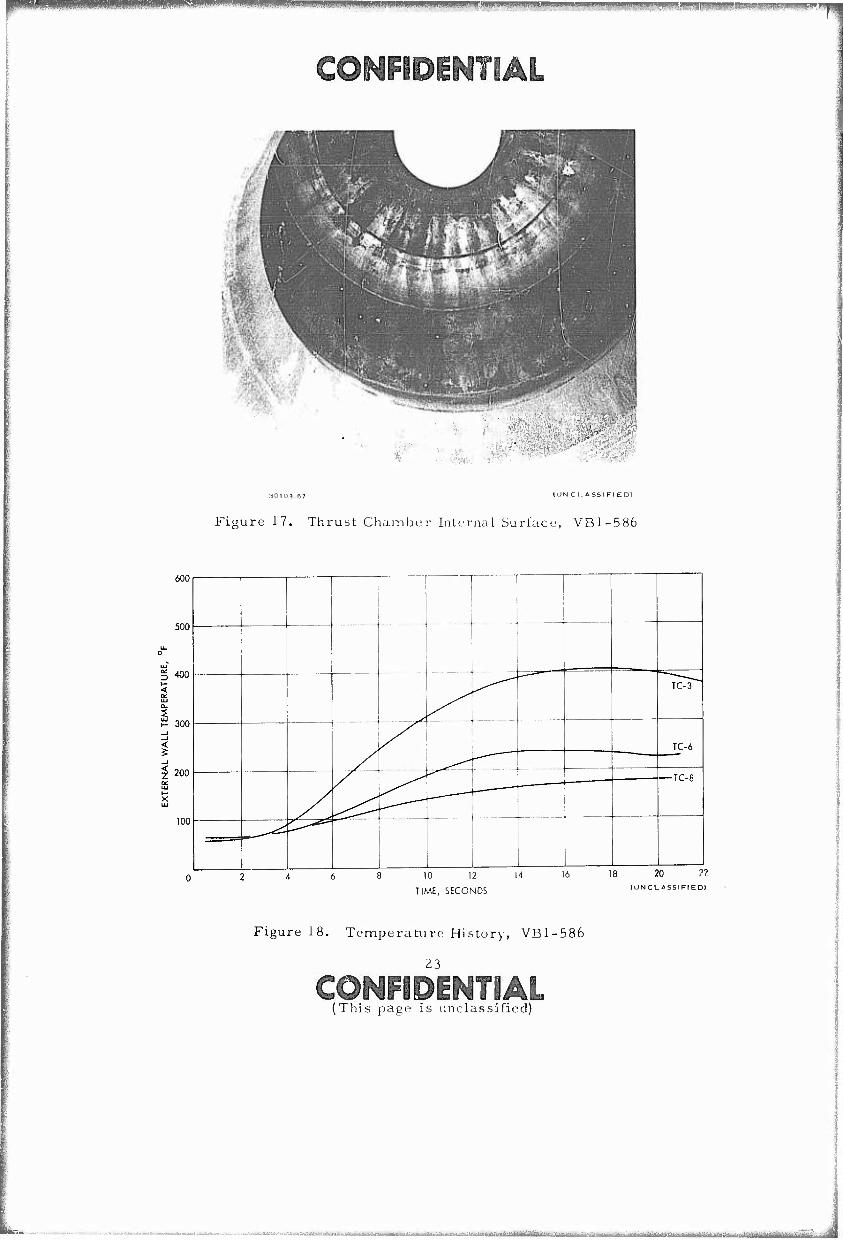
17. Thrust Chamber Internal Surface, VB1-586 23
18. Temperature History, VB1-586 23
19. Injector Scaling Comparison 25
20. Steel Conical Pintle Tip and Thrust Chamber 26
21. Explosive Charge Configuration 28
22. Listrumentation Installation 28
v
UNCLASSIFliP
m^wmBjlK.iMg^v.^.J^ ffla^a^^^^»,^,^^,^-^
jiiiuiwnjmwiiii ?r«'^*v?Jww™^$*.(l^^^^ffi^T mmmmmmmmmmm. mmmmm^mmmmffmmmmmm
UNCLASSIFIED ILLUSTRATIONS (Continued)
Page
23. Explosive Charge and Photocon Location 30
24. Schematic Repreoentation of Explosive Charge and Instrumentation Location 30
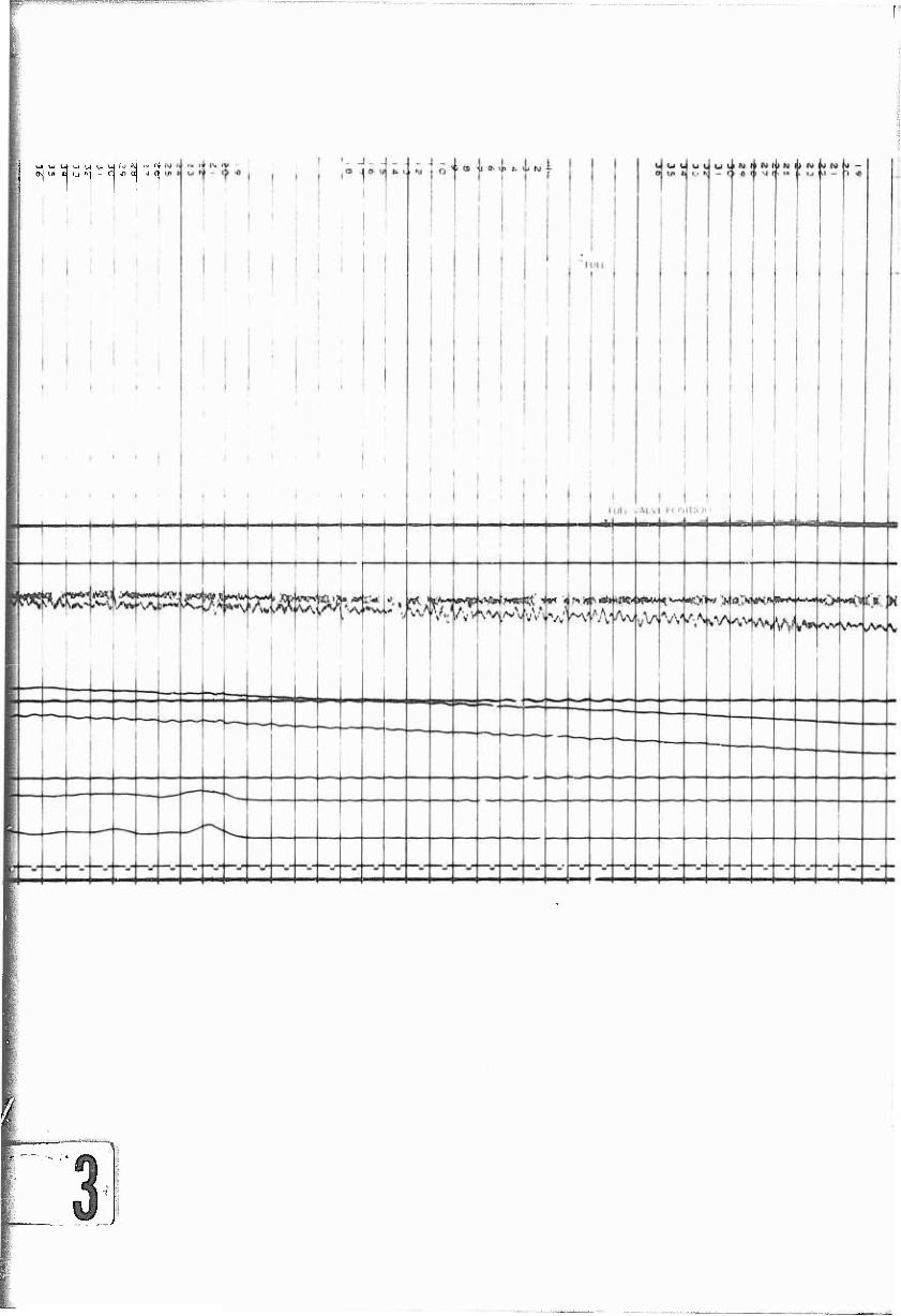
25. VB1-594 Start Transient Oscillograph Reproduction 31
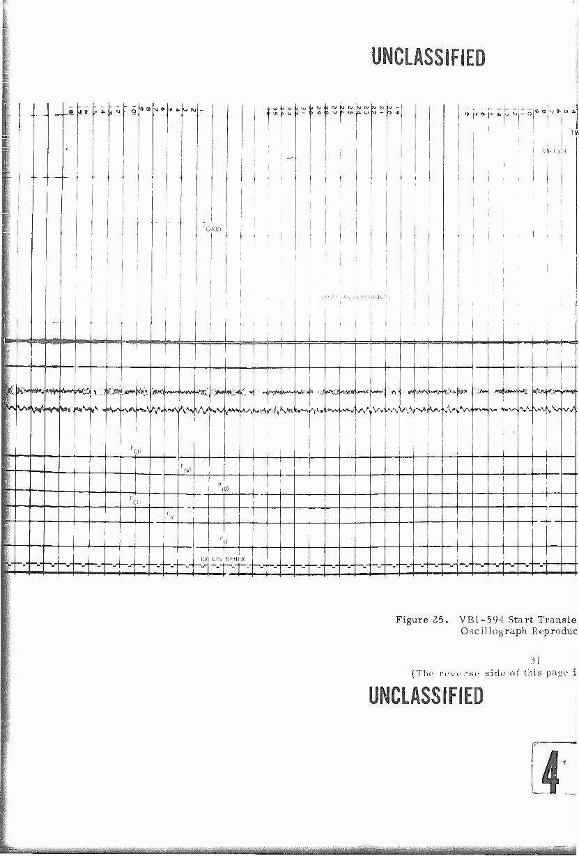
26. VB1-595 Oscillograph (No. 1) from Before Charge Detonation to 150 msec After Detonation 33
27. Test VB1-595, Oscillograph of High Response Trans- ducers Showing Explosive Charge Detonation 34
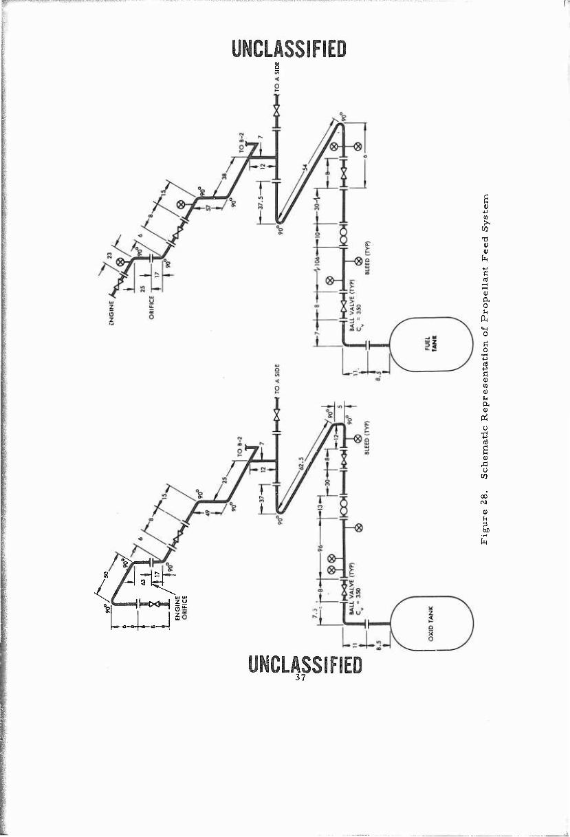
28. Schematic Representation of Propellant Feed System 37
29. Explosive Charge and Instrumentation Location 38
30. Thermocouple Identificaton and Location 3g
31. Theoretical Frozen Characteristic Exhaust Velocity _ _ ^
VI
UNCLASSIFIED
^ — — "■■'■■"—"■—'-'-""""-"■-^■^■■^ - ■■— • --^'-^'TiMiW in-Tt iiii'iwr^aigTiiiiHiimiii'imiii m mwmmnwmmMtiim
VWimammK i. J.i .j wiipBiBHwwMiij|i|i|i i^BWWg*Wiwwww!>mmw^^M^
UNCLASSIFIED SECTION I
INTRODUCTION
(U) This report is issued by TRW Systems pursuant to the require- ments of Contract AF 04(61 1)-1 1 382, Modification No. 3, "Advancement of Injector and Thrust Chamber Technology," dated 21 March 1967. The objectives of the program were to demonstrate the scalability of the LMDE coaxial injector, with respect to performance and dynamic combustion stability, to much higher thrust levels than had ever been run with this type injector. Additionally, it was intended to show that fabrication using commercial, heavy-industry fabrication techniques would result in accept- able hardware.
(U) The purpose of the program was to obtain the fundamental data necessary to provide a firm basis for scaling the IAIDE coaxial injector design to multimillion-pound thrust, first-stage booster engines of maxi- mum "cost-effectiveness. " The first step in scaling the LMDE injector was a scale-up of 25-to-l, or a thrust level of 250, 000 Ibf. This size is great enough to determine if the injection principle is scalable with regard to both performance and combustion stability.
(U) Because of facility limitations at the TRW San Juan Capistrano Test Site (CTS) the program would employ full size hardware (approxi- mately 3-1/2 foot diameter thrust chamber) but would operate at a reduced thrust level. This requires that the injector be throttled, a more severe requirement for the demonstration of high performance, without invalidating the demonstration of the comb\istion stability characteristics of the coaxial injector. This size hardware also makes it possible to investigate large rocket engine construction using commercial, industrial fabrication tech- niques with relatively few "precision" tolerances.
UNCLASSIFIED
Art(tii,^iwUMjeüM&^^^&^*^^ v i".^ -i: -'iUv^iiiL^-1^-' ^u.,^^^^^^,,^^11

KW)«'I'lUS; iBWAW-'Ji™»»« *m!mmm<mm.w!wmn!ww mwmmäzmmmi^vm^mtmmmmi'vm&m ■ ; ■ -■- ■ •
UNCLASSIFIED SECTION II
TECHNICAL DISCUSSION
1. ENGINE DESIGN AND FABRICATION
1.1 Design Approach
(U) TRW approached the engine design with the objective of mini- mizing both the recurring (production) costs and nonrecurring (develop- ment) costs. The engine is pressure fed, uses storable propellants (N?04/UDMH) which are compatible with conventional materials of construction and for flight-weight versions would emplcy a sacrifical liner in a steel thrust chamber shell. The engine utilizes a centrally- located, coaxial injector which has demonstrated high performance and inherent dynamic combustion stability at thrust levels of 10, 500 pounds and less. The coaxial injector had been scaled previously over a 20-to-i range (525 tc 10, 500 lb ).
1.1.1 Z50, 000 Ibf Thrust Static Test Engine Design
(U) The design of the static test engine fired in this test program is shown in Figure 1 and the actual engine (including thrust mount), as fabricated, is shown in Figure 2 during installation in position Bl of the Vertical Engine Test Stand (VETS) at the TRW San Juan Capistrano Test Site (CTS). The static test engine consists of two major assemblies — the centrally located, coaxial injector and the uncooled thrust chamber. The static test engine thrust chamber is designed to operate as a simple heat sink chamber with a rating of 250,000 pounds thrust at 300 psia. Test firing durations are therefore limited by the heat-sink capacity of the chamber. Facility limitations at CTS, primarily feed system and main support structure, required that the engine be operated at a maxi- mum of 50, 000 pounds thrust. This resulted in thrust chamber opera- tion at a nominal chamber pressure of 60 psia.
1.1.2 Component Design — Injector Element
JU) The centrally located injector element, which was fabricated using industrial fabrication techniques, is shown in Figure 3 prior to start of hydraulic testing. Fuel is admitted to the injector element through a single 5-inch flanged inlet on a toroidal manifold. Fuel flows from the manifold through eight 3-inch-diameter holes in the outer jacket, then over the weir and is injected into the chamber through a singular annular orifice. Oxidizer is admitted to the pintle tube through a single 8-inch-diameter flanged inlet at the head-end of the engine. The primary oxidizer injection orifices are keyhole slots; thirty-six of these primary slots are distributed around the oxidizer pintle tube with thirty- six rectangular secondary slots interspaced equally between the primary slots.
WCUSSfFED

ORIFI RINI
FILLED WITI "RUBBER
\ ■
38.29 DIA
OXIDIZER PRIMARY ORI FICE
OXIDIZER SECOND ORIFICE
1

UNCLASSIFIED
16-, 150UB, R.F., SO. FLANGE, A181.C/STL
±0 J "t tn,
:x
FUEL INLET
.ISO LB 8" WELDING NECK FLANGE
B.625 CIA
, OXIDIZER INLET
0 1 2 3 4 5
SCALE IINCHESI
20
Figure 1. Static Test Engine Assen 250,000 lb. Thrust
(SK401408 A)
(The reverse side of this page is blank) «LMFEO
<L-^ , ■■ ■ .■.■■■...■ . ■ ■ ■ ; ■ : ^-1

■R^--1,1"-.:!... T.-w^.'-rw;.»-".? .',■ ■^■■.^».lflWJ^iWlVWMÄVW'r^f''^'^^'^'•', ■■ ■■■■■■■.. '.
UNCLASSIFIED
16". 150LB, R.r SO. FLANGE. A181.C/5TL.
FUEL INLET
ISO LD B- WELDING NECK FLAMGE
B.626 DIA
XID'ZER INLET j
i
0 i 2 3 4 5 20
SCALE IINCHESI
Figure 1. Static Test Engine Assembly 250, 000 lbf Thrust
(SK401408 A)
(The reverse side of this page is blank)
.,....., ; - .<_ ^ . : ■ . ^. , ■- ■-■•■:-- ■ v.4^^W..»;.^

jiimniiiwjpnHinippiiPiii^^ Biiiiiipmiiiiiniiipi;inimiii., ■"■ i' f .1 <• ,wm •■""■• wmm ■■■-U.HJHW. Wmvwwy
mmmmmi
(UNCL ASSI FIED)
Figure Z. Photograph of Static Test Engine Installation
@o)MCMOTIM (This page is unclassified)
_:. _ ., . -.. .._ : J :__-__ . ^._ . ̂^^^^^„^„....^^a.^^..^^.^^^.^ ^-^ ^^^^.^.^.^.^ ^^ ^

|j||||iPi|(iP^IPBPlBl«sw*!^^
(g@OT©[l^¥IÄt
CIRCUMFERENTIAL FUEL MANIFOLD
PRIMARY OXIDIZER ORIFICE (36)
1DIZER INLET FLANGE
5 INCH FUEu NLET FLANGE
FUEL INJECTION ORIFICE
SECONDARY OXIDIZER ORIFICE (36)
(CONFIDENTIAL)
Figure 3. Coaxial Injector
(U) Since the flow passages and injector orifices are sized for 250, 000 lb£ flow rates it was necessary to throttle the injection orifices so that the desired injection AP's could be obtained at the reduced flow rates. The annular fuel orifice was fabricated with the required annular opening for the Z50, 000 lb, thrust fuel flow rate. A sleeve to fit over the oxidizer pintle tube was falaricated to reduce the fuel opening. This sleeve incorporated 1Z support vanes to center the oxidizer pintle within the fuel jacket opening. Initial hydraulic testing of this configuration disclosed considerable discontinuities in the fuel sheet which were caused by the twelve support vanes. Therefore, the outer fuel jacket assembly was reworked as shown in Figure 4 to incorporate a replace- able fuel orifice ring. The orifice blank was made as shown in Figure 4 and the annular opening was varied by machining the I.D. of the orifice blank to the desired dimension.
(U) The oxidizer orifices are throttled by positioning the flow spreader within the oxidizer pintle tube to close off as much of the prima- ry oxidizer orifices as desired. Figure 1. The orifice size and configura- tion were based on hydraulic test results of a previous model which was tested only at the full-flow position. Initial hydraulic testing of the injector indicated a greater discharge coefficient than that measured with the hydraulic test model. This required that the flow spreader be repositioned (blanking off more of the primary orifice) to obtain the desired injection AP. As a result, a higher percentage of the flow, nearly twice the design value, was injected through the secondary orifices. 5
©gMPENTIAL
iiiffriMaiMiliaitii^iilltfirrr .. . 3^'Vi^^'"riiaiWY^itriirtL'iffiiiftM;rf^jii,r ■ .- ^.i.-, ^^-^k^- - ^rifflmiigrii i iÖääasääE*fe«i»ii-r^

f pw« mmm ^^ ■BWiBlliMiWW^WMu iillffAW'.^ti'ii'il^W-WW^Wi^W^^
"THE mromrioi ADO TerH*ic«L DATA OIICLOIED B> THIS DOCUHENI HAT BE DIED umui RElTIICTIONIYANOFORTHEUIIITEOlTATElGOVERNIIERTIHEItDELlVEREOUNDEItGOVERAIlENT
CONTRACT, EXCEPT IHEN A LIHITED RICHTE LECERD PER ASPR VNl ALTO APPEARS OR I*IT DOCURERT.ARDHATeEUIEDBVOTHERCUSTOyERlOFTRRlTITEHlRHERERICHTlAREEXPRECLT
CHANTED BY A TRI STITEUS CORTRACT. EXCEPT A] ROTED ABOVE. THE IRPORVATIOR ARO
TECHNICAL DATA DITCLOIEO BY THII OOCUHERT ARE PROPRIETARY TO TRi lYITEtll ARD RAY
ROT BE UtECREPRODUCED.OR DISSElilNATED TO OTHER! EXCEPT WHERE RECEBARY IDCORPIY
IITH A TRI ITlTEMt CORTRACT OR AS AUTHORIZED IR IRITINC BY TRI SYSTEKS."
/O - 32 UA/f 3A THD x .so oeep
"/S HOL£S £C). SttAtSSO TO M^ rar-f SK -40/& 5si
r- ruSL. ^Js-^KeT'
/3.2ÖO
/5.3<Z5 O/xl
1—1
DM
'■*
S.FIT FO SK-4CI/65S
/?£A70l/£ T/ilS
\l (VEH/ PA/ST)
[I] ISSWOKK ru£l- -Js4CI<£T FSCD/^I 3/< ■4-O/Ji': M^/ecToje ^-5.sv ^is SS-/C>H/*J OU THIS
I. IDENTIFICATION MARKING IN ACCORDANCE WITH TRW SYSTEMS SPEC. PR 121
TYPE -2" CUSS /E?- PART NUMBER . - -
NOTES; UNLESS OTHERWISE SPECIFIED
PMT M IMHtimM) Na
FOZJ- JOCKEI
HUT TRtAT
I. i;... z. oaa
APPI.ICAOLE SPtCIFICATIOHS
7.00,
0135 TH
Ä1TM
.751TM
.vt*.!****^*^ .^.^.^^^^^^^^^«^^^^ Ü MjättfifaflaM

^iW»J4IWI'^TO»rf;t':lWt^WA».gi>.;aj'vg'i''f"''J'-' •^-'-
PMClLÄSSD^Bg© DATE APPROrtO
_ /o - ?a UK//? SA THD x so oeep
*ia liOL£S £<?. sf^-Aaeu TO A14 re/-/ ^5/c -^o/s. 5s
ae/r/ce; BL-*4/UK.
■5K 4-0/394- fUEL JACKET
/S. 365 DIA
/■*. „ IS L *IA
I4C-Z5 OIA
's.ae,s o/x\ S. FIT FOE
THIS M/ITZßML
SO . U ■I. SO
IS. 365 OM
THIS VIA-
TO se. as T£ieMJM£0
-5.00 -
OSTAIL o/=
IUNCLA5SIFIEDI
PMT m locrnirriNa Na
FC/£i. u^CA£7 •MTT NAMC
NOUEHOATURE Ofl DriCmPTlOU
PARTS LIST
USED 0« KOtI ASjr
APPllcÄriON
HEAT IMAI
APPLICABLE SPECIFICATIOHS
UNLESS 0THEBWI5E SPECiRED
L ihltUfWT f« MIWTO-» 2. DUOMKMl AX( IN WM-tpK. 1 5UWM» TUTU« CSJ 4. «u win TO WTIT uron FUTIW
m cowvutsk-« CMUHO.
5. KlUCVt DUBM ft UMR CDOCa. 6. nXERANC» m
DCC1UMJ XC7.xi)10
AHOLU ■I* IUCNMIDZO'SO' OTr«« * 2*
7. sie iioa lourjvtcu.
\ss* -.001
■i-005 -jOOl t.010
0135
2S1 THRU ,!«l
.751 Twniijno;
A*-"? .126 THRU 250
.501 IKHU .Wtjoi
1,001 THRU UOOtJoi
DO NOT SCALE DRAWING
irtlitluHÜ
wrori tuocum TB»
■posff
TRWSVS7KSAS OMB «WtC« I'AWK ' WRPOUDO WlfcCK C^lgOgM*
iMOOIF/CA T/OA/ 250,000 Lßf //JJJfCTQ/Z
D CDOC IDCNT Ha
11982 5K40/7/^ J4L. 3!
Figure 4. Fuel Jacket Modification 250, 000 lbf Injector
(The reverse side of this.page is blank)
UNCLASSIFIED (U) For injector configuration No. 2 a new flow spreader was
machined which provided about 50 percent less flow through the secon- dary orifices than was obtained with injector configuration No. 1.
(U) The original injector configuration incorporated a silicone rubber pintle tip. The material employed for the pintle tip was Dow- Corning ZO-103 which in a two-part room-temperature vulcanizing (RTV) material consisting of a silicone rubber base and catalyst. The DC20-103 silicone rubber base incorporates a mineral filler. There are no special preparations required for applying the insulating rubber. The surface to which the rubber is to be applied is prepared by cleaning and degreasing after which a coat of primer is applied to the surface. The two parts of the RTV material are then mixed and applied with a spatula. The material remains workable for approximately two hours and may be contoured as shown in the figure.
(U) Injector configuration No. 2 employed a conical steel pintle tip which was welded to the orifice sleeve. The void between the flow-spreader and pintle tip was filled with an RTV material.
(U) Fabrication of the injector was from commercially available carbon steel pipe and flanges which were assembled by welding. Only three specially machined parts were used in the assembly. They are: (1) oxidizer orifice ring, (2) flow spreader, and (3) fuel orifice ring. The parts were normally assembled by tack-welding with the final welds being made automatically on a submerged arc welder.
1.1.3 Component Design—Thrust Chamber
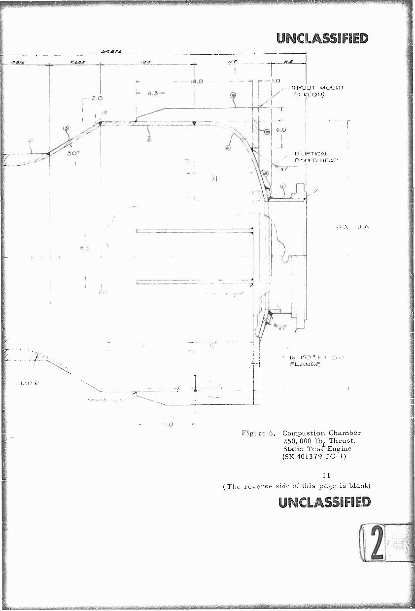
(U) Figure 5 is a photograph of the thrust chamber (with thrust mount) prior to assembly of the injector into the chamber. The design of the 250,000 lb£ thrust static test engine thrust chamber which was fab- ricated using industrial fabrication techniques, is shown in Figure 6. The thrust chamber has been designed to operate as a simple heat-sink chamber to permit test durations of 5 seconds continuous firing at the full thrust level without exceeding an external \Vall temperature of 600oF. These design conditions resulted in the selection of an 0.5-inch wall thickness material.
(U) A T-1 steel alloy was originally chosen for fabrication of the thrust chamber. A quoted 8-week delivery schedule for an elliptical dome of T-l steel necessitated a change in material to 4130 alloy steel. The thrust chamber consists of an elliptical dome, a rolled and welded cylindrical section, a conical rolled and welded converging section, a machined throat section, and a conical rolled and welded expansion section. The injector support and attachment flange plus the thrust mount ring and support brackets were made an integral part of the thrust chamber.
(U) The chamber sections were joined together using tack welds with automatic submerged arc used for completion of all circumferential welds. All internal weld joints were ground smooth following the weld- ing operation. No internal insulation was used in the thrust chamber.
ycmÄSiDF»
_ ^ ■■. , , , ^ ; -^ '

UNCLASSIFIED
J N C L A S S I f- I F D
FisMirr 5. Thrust ChainbiT Frmr ti. iujcitor Asbnnbly
Fabrication of the injector, thrust chamber, and thrust mount was by J.C. Fabricators, Gardena, California. The,' test support machine shop at CTS finished-machined the oxidizer orifice ring and flow spreader and reworked the injector to incorporate the replaceable fuel orifice.
1.1.4 Component Design—Engine Controls
(U) Three-inch stainless steel Jamesbury ball valves, using modified Jamesbury pneumatic actuators, were utilized as engine shut- off valves. The shutoff valves were mated directly to the injector inlet reducers. An 8- to 3-inch reducer was used as a connection piece between the 3-inch shutoff valve and the 8-inch, 150 lb R.F.S.O. flange used as the oxidizer inlet. A 5- to 3-inch reducer was utilized on the fuel side. The shutoff valve sequence was controlled through micro- switch circuitry to insure an oxidizer lead start and oxidizer lag shutdown. Cavitating Venturis were installed in the propellant feed lines downstream of the stand position valves in order to limit the propellant flow rates and assure on-mixture ratio operation. Figure 7 shows the engine installed on VETS position V> \ prior to the initial firing.
1.1.5 Instrumentation
(U) A detailed description of the instrumentation utilized during the testing, and the locations of the pickups are provided in Appendix II, page 38.
10
UNCLASSIFIED

ipillJPPIPpiljllp^tuJi.^
^■f.sr^s-
V I
3a.2i5 DIA
27.0 DIA
20'
^- .50 TYP
>»
I I.50 R
Y(-
"1^7
9.0
17.25 ' KEF
H.
: ^i^^i^i, ja^.a^^.^L^1>k^a>..i^,^^"i-^'.«.. ; ^. ,,l, —^JL...
fmmu ^mm plilliBpppjj,UJMii|!i^^m<P^^u,--t.a^
I I.SO R
UNCLASSIFIED ^.-fST-^-
y/.s
-I.O I ,—THRUST MOUkIT
(A REQD)
ELLIPTICAL DISHED HEAD
^O.v IJIA
'^ :L i
4-
i_j
i~\b . i50 " r- r s t; FLANJGE
Figure 6. Compustion Chamber 250, 000 lb. Thrust, Static Test Engine (SK 401379 JC-1)
11
(The reverse side of this page is blank)
UNCLASSKF»
iiimi-fi»f:^"^^a^-^^'^'"'"^-'-i^a^'i^-¥#Mt^^

mmmmmmm^ "nT-TT-TTT^: rwnwww^-^^-u**^ ^jp^-^r.-; ' ^TA'^^im^
Ü1MC
OX1D1ZER FIRE VALVE
OXIDiZER FEED LINE (3 INCH)
THRUST MOUNT
THRUST MOUi !T PAD
FUEL FIRE VALVE
FUEL FEED LINE (3 INCH)
VENTURI LOCATION
EXPLOSIVE CHARGE LOCATION
IUNCLASSI FIED)
Figure 7. Engine Installation on VETS Bl
2. VETS B-l STAND MODIFICATION
(U) Paragraph 2.5 of the aforementioned contract specified the modification of Vertical Engine Test Stand (VETS) B-l position at the Capistrano Test Site to accept the TCA for engine testing.
(U) VETS position B- . has been utilized as a 10, 000 lb thrust sea- level test position on the I.MDE development program. The major modi- fications to the test position included: (1) removal of all LMDE position equipment and fluid lines, (2) modification of the propellant feed systems to reduce pressure losses between propellant tankage and the engine, (3) installation of high pressure GN-, storage trailers and high flow pres- sure regulators, and (4) fabrication of a 250, 000 lbf thrust mount.
(U) Utilization of the VETS B-I position for this test program required complete removal of the LMDE thrust mount and load ceil, the LiviDE coolant water plumbing, the thrust ring firex plumbing, and the flush and purge plumbing. Modification of the propellant feed system required removal of the lank outlet filters, the 1-1/2 inch flowmeter loops, and the screen filter spool pieces downstream of the B-l position valves. These items were replaced with 3-inch stainless steel spool pieces, 3-inch flowmeters with 3-inch outlet and inlet stainless steel sections, and 3-inch 90-degree elbows, respectively. A schematic of the propellant feed system is given in Appendix I.
13
ÖJ EMI C LASS D [F D E ©

1 Jl WIHIIPIIIIIWWPIWM ^ittWIiKMWfflWWWMP)^
UNCLASSIFIED (U) The complete propellant tank pressurization system was re-
placed with larger stainless steel piping and Series 400 Grove pressure reguleitors installed as close as possible to the propellant tanks. Mobile high-pressure GN, storage trailers (317. 51t3 capacity) were placed adjacent to the test stand in order to provide sufficient GN2 reserve. The individual trailers, one for oxidizer and one for fuel, were close- coupled plumbed to the Series 400 Grove pressure regulators.
(U) A four-legged thrust mount with legs connected with a circular ring was designed and fabricated to transmit thrust loads from the TCA to the stand structure. The thrust mount was bolted to thrust mount pads which were welded to the 36-inch-wide flange beams supporting the thrust ring in the test stand. A coolant water spray bar was installed at the exit plane of the nozzle to prevent overheating of the stand lower level wiring and plumbing.
(U) New GN? purge and H?0 flush systems were fabricated for both the oxidizer and fuel side of the injector.
3. PERFORMANCE EVALUATION
(U) As required in paragraph 2.6 of the contract (modification No. 3), two test series totaling twelve short duration hot-firing tests were made at a nominal thrust level of 50, 000 pounds and a nominal chamber pressure level of 65 psia. These two test series experimentally explored the influence of momentum ratio, mixture ratio, and chamber pressure on combustion efficiency (as determined by C* measurements). Hydraulic testing of the injector to determine the injection spray pattern for correlation with hot-firing test results preceded the firing of each injector configuration.
3. I Hydraulic Testing— Initial Injector Configuration
(U) Following completion of the engine installation on VETS B-l the coaxial injector was removed from the TCA and installed on the Propulsion Integration Test Stand (PITS) for hydraulic testing. Preliminary hydraulic testing of the injector indicated unacceptable hydraulic characteristics (streaking) of the cylindrical fuel sheet. This characteristic was caused by the IZ vanes used to center the pintle tube (flowing oxidizer) within the fuel ori' -e. In addition, the measured oxidizer injection AP was consid- erably 1 .wer than expected in the throttled position. This was attributed to a higher than anticipated discharge coefficient (C ,) in the throttled position.
3.1.1 Injector Configuration No. 1
(U) In order to eliminate the streakiness caused by the 12 support vanes the fuel jacket was redesigned to incorporate a replaceable fuel orifice ring. The pintle tube was then centered within the fuel orifice through use of set screws upstream of the fuel orifice. Hydraulic test- ing of the injector was resumed following completion of the injector rework. Figures 8 and 9 show the injector oxidizer streams being hydrau- lically tested separately and in combined flow with the fuel sheet.
14
TOeiMiPoiiE)
^.„J^.^^^ai^.^ -^±^ ^ ^..^ ..-;. -.^^L^yü ■ iff I iiim-iüiif jj. '^•''■■'"■^^''■ä-ir^iM{f^Mtöii^f-t'

^^TrwirT^wiwi^r^ry'Tirr^'r™^
y^CLASSÖFIIE)
.; •
;
30060-6-, (UNCLASSIFIED)
Figure 8 . Oxidizer Flow Pattern, Injector Configuration No. 1
x . lX ,Y -vi^^p*-'
- ■ ■ -' '"■! ^ '
■
-.■/ /'■■■;''•" ■-'■■' ■■'■■ ■ ' ">
: .... i . i/..
30053-67 (UNCLASSIF.ED)
Figure 9. Combined Flow Pattern, Injector Configuration No. 1
15
UNCLASSrFIED
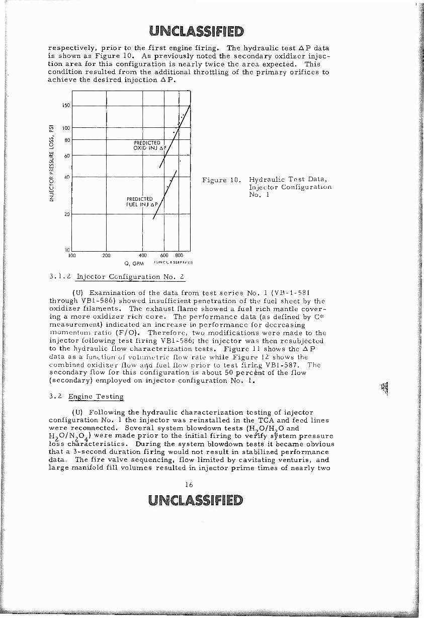
ycmAigDF» respectively, prior to the first engine firing. The hydraulic test AP data is shown as Figure 10. As previously noted the secondary oxidizer injec- tion area for this configuration is nearly twice the area expected. This condition resulted from the additional throttling of the primary orifices to achieve the desired injection A P.
o
o u
150
100
80
A / PRE
OX DICTED D iNJ A
/ 60
'0
/ /
•
/
20
PREDK FUEL 1
TED / MJ AP/
/
/
n ....
Figure 10. Hydraulic Test Data, Injector Configuration No. 1
100 200 400 600 800
Q, GPM IUNCLA5SIFIFÜ)
3.1.Z Injector Configuration No. Z
(U) Examination of the data from test series No. 1 (VB-1-581 through VB1-586) showed insufficient penetration of the fuel sheet by the oxidizer filaments. The exhaust flame showed a fuel rich mantle cover- ing a more oxidizer rich core. The performance data (as defined by C:':
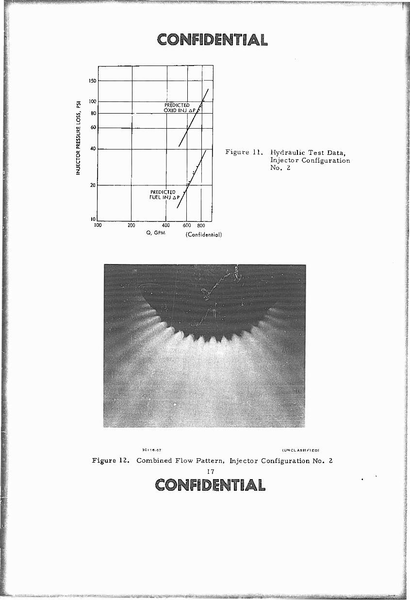
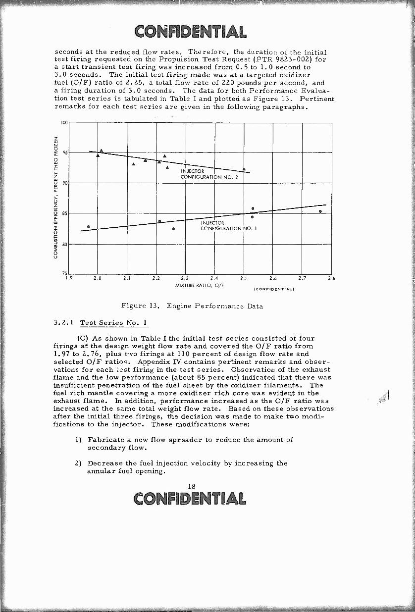
measurement) indicated an increase in performance for decreasing momentum ratio (F/O). Therefore, two modifications were made to the injector following test firing VB1-586; the injector was then resubjected to the hydraulic flow characterization tests. Figure 11 shows the AP data as a function of volumetric flow rale while Figure 12 shows the combined oxidizer flow ai\d fuel flow prior to test firing VB1-587. The secondary flow for this configuration is about 50 percent of the flow (secondary) employed on injector configuration No. 1.
3. 2 Engine Testing
(U) Following the hydraulic characterization testing of injector configuration No. 1 the injector was reinstalled in the TCA and feed lines were reconnected. Several system blowdown tests (H?0/H-,0 and H->0/N20 ) were made prior to the initial firing to verify system pressure loss characteristics. During the system blowdown tests it became obvious that a 3-second duration firing would not result in stabilized performance data, The fire valve sequencing, flow limited by cavitating Venturis, and large manifold fill volumes resulted in injector prime times of nearly two
16
ycmMSDiFDiiS)
, :i ^^
mm iwrwpwww'-.jAjji^^wwM^w^^ mwu*m*MrmMmr>'!*m?m*rm
mmmmmi
a: a-
o I-
150
IOC
80
60
40
20
10
/ PREDICTED / ÖXID INJ AP/
/
/
/
/
PREDIC FUEL Ih
TED y1
JJ AP/
/^
100
Figure 11. Hydraulic Test Data, Injector Configuration No. 2
200 400 600 800
Q' GPM (Confidential)
(UNCLASSIFIED)
Figure 12. Combined Flow Pattern, Injector Configuration No. 2
17
COKPIPiMTDM
■«9 --.-■--. ^^^^-.^^.^..^^^...^ ^J.;,^.^^^^^ -^^fe^ ,
mmmmmm IWIP mmmmß
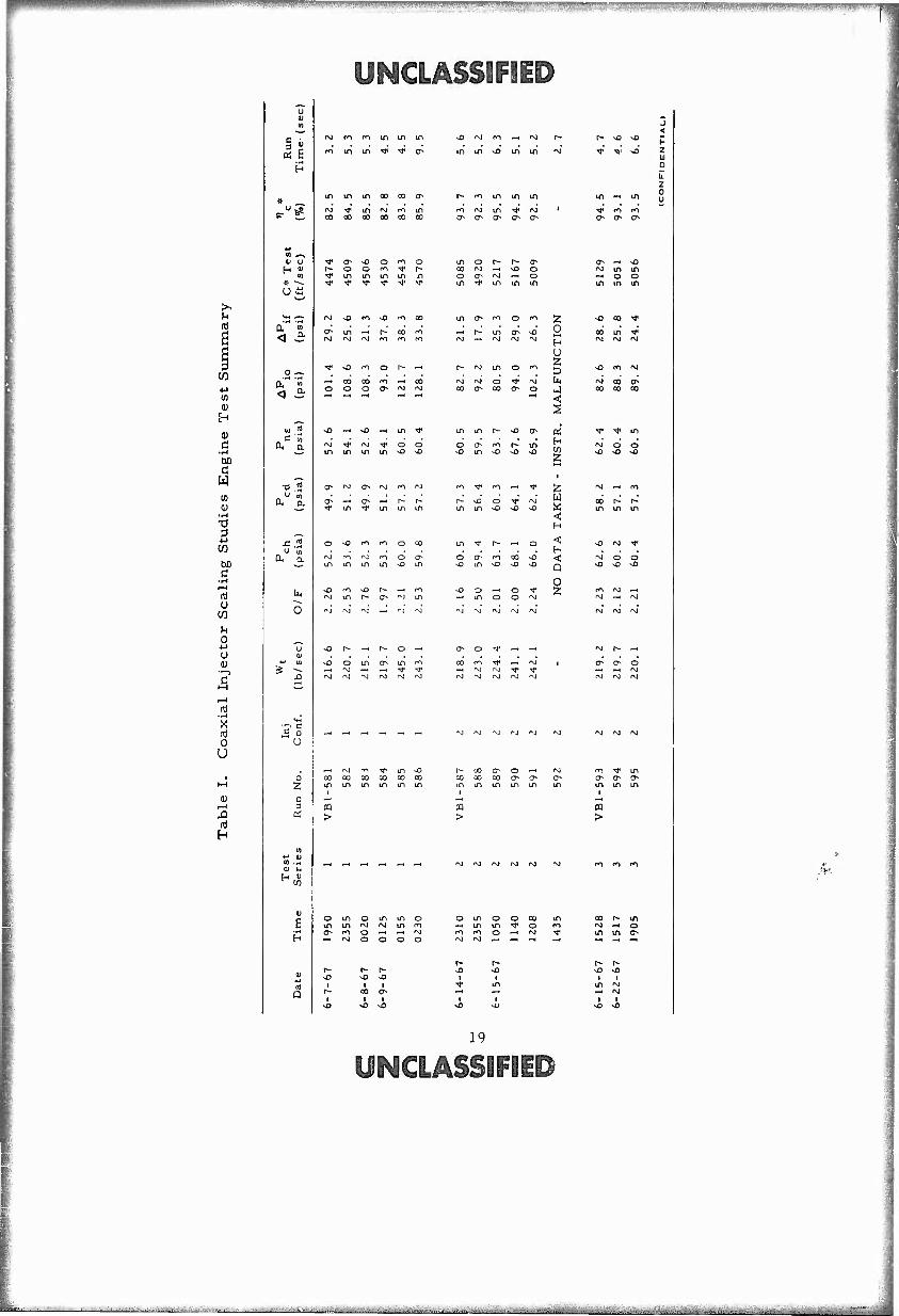
^©[^[PDPIlG^l'flÄL seconds at the reduced flow rates. Therefore, the duration of the initial test firing requested on the Propulsion Test Request (PTR 9823-002) for a start transient test firing was increased from 0. 5 to 1.0 second to 3.0 seconds. The initial test firing made was at a targeted oxidizer fuel (O/F) ratio of 2.25, a total flow rate of 220 pounds per second, and a firing duration of 3.0 seconds. The data for both Performance Evalua- tion test series is tabulated in Table I and plotted as Figure 13. Pertinent remarks for each test series are given in the following paragraphs.
100
N o ^ 95 a. 7J
o uj I
U 90
>- u z U 85
Z a
s o u
75
* i
A
A
INJECTOR —-—-—JL, CONFIGURATION NO. 2
I 1
• • - ■ """ •
~———~ J " INJECTOR • • GONE IGURATION \|0. 1
1.9 2.0 2.1 2.2 2.3 2.4
MIXTURE RATIO, O/F
2.5 2.6
(CONFIDENTIAL)
2.7 2.8
Figure 13. Engine Performance Data
3.2,1 Test Series No. 1
(C) As shown in Table I the initial test series consisted of four firings at the design weight flow rate and covered the O/F ratio from 1.97 to 2.76, plus two firings at 110 percent of design flow rate and selected O/F ratios. Appendix IV contains pertinent remarks and obser- vations for each iest firing in the test series. Observation of the exhaust flame and the low performance (about 85 percent) indicated that there was insufficient penetration of the fuel sheet by the oxidizer filaments. The fuel rich mantle covering a more oxidizer rich core was evident in the exhaust flame. In addition, performance increased as the O/F ratio was increased at the same total weight flow rate. Based on these observations after the initial three firings, the decision was made to make two modi- fications to the injector. These modifications were:
1) Fabricate a new flow spreader to reduce the amount of secondary flow.
2) Decrease the fuel injection velocity by increasing the annular fuel opening.
©oOTPiOTDM
"*■"""- .. ^aüMi mmL. : ■^*******^ tiriViMiiMiiitfiiiifMiriiii .^.^.^^^^■^^
w^mmmmmmmBmmmm WW!««W!W!W^W^
yM€ILħiQ^DgP
^^ppp^ppnip^ipppipii
o U
^3
H
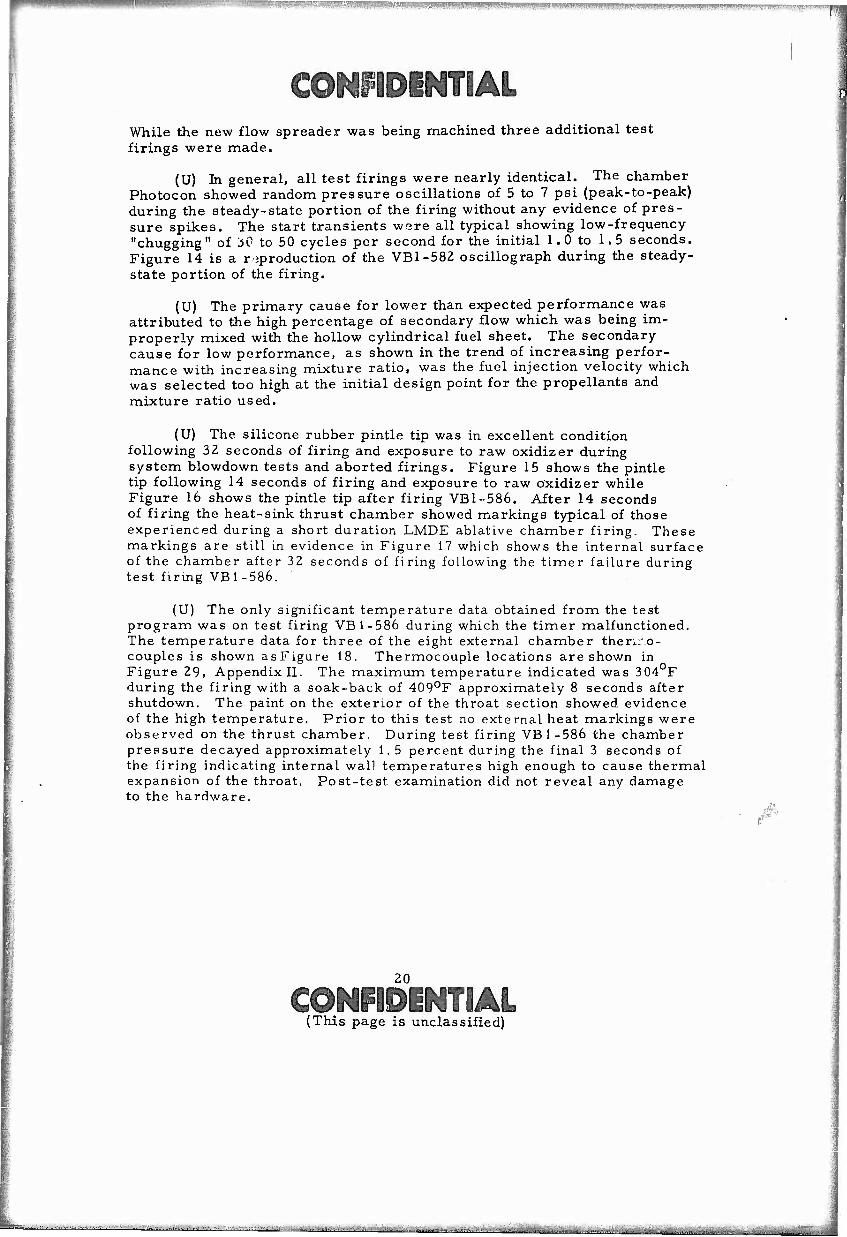
m in m 00 00 o # pu£
fN) ■^" m rsj f-t in 00 O) CO 00 CO 00
(U u
u a
0, n
< 3
o —
< 3
•o 2
■c.2 u S
A a
In
O
IS U
o 2
n! Q
r^j m fo m in
ro m m ^J* ^
a> ^o o fo O O ro 'T in m in in
sO m ^o
in —» Is- rM rvj »M
co 00 rn ^ 00
ND -H ■o —* m ^f
in m
>
Qs rsj fO fM
m m
^ rO rO
rvj r^ rg rO o O^ m m m m ^o m
rg rg rvj
vO r- -H
vD o m
rg rj ^J
o —<
in fo
rg rsj fM
00 CO 00 CO 00 00 m m m m m m
^X) r\) ro ^ rg
m in ^> m in
m m m in
CT^ Q^ ^ o^ 0s
M —. NO o~- »NJ -^ ■»j* in in
m o (^t o ro ^;
-** r-' in a^ so 2 rsj ^H rg rg CM ,
u r- fvj m o ro K-J
rg rg o M* »N U( 00 0s 00 o^ o J
m in r^ -o 0s oi o c> rn r-* in [tj vo m NO o o ^
ro TJ" en —< ^ ^
r-* vo o V rg W m m vO o vO X
< H
in I1 r~ — o ^
o t> rn co ^o < ■£) in o ^ sO Q
o vo o -< o -^ 2; -< in o o ^ rvj rvj rvj rg rsj
CT^ O ^f —' —•
00 rn Tf —. fSJ I —. rsj rg -^ -^ rg rg rg rj t-g
rg i^j rvj r\j f^
co oo oo o a^ m m in m m
CQ >
rg rg fM rg
o in o in in o o in o o ai in in in ro f\) in CO _H Ul in •* o ro o m o ^H -H -M m m o —i 'S! 1' ^H rg o o o o ng
r- t^ r- r^ ■o -o vD -o ~o i i
J < r- ^ •O
h
^^; •V vO z
111 Ü
a z
in — in 0 u
^; ro ro
a- (T- O^
in
in o m
in o in
vD CO if
00 in fg
vO CO *M
in in in
o no
rg o
rg —. rg
rg rsj rg
O^ O O
rg rg nj
rj ^J rg
>
CO rg in in
t-
in rg rg
'-■
19
UMCIASSIFDI©
u^E
!P^W*s»a^l»WllWiWI!!!^^ tT-^-n-'--. ---■■ —-■—-.-:iv-v:- -.-'■-.■■.
mmmm&\L While the new flow spreader was being machined three additional test firings were made.
(U) In general, all test firings were nearly identical. The chamber Photocon showed random pressure oscillations of 5 to 7 psi (peak-to-peak) during the steady-state portion of the firing without any evidence of pres- sure spikes. The start transients were all typical showing low-frequency "chugging" of 30 to 50 cycles per second for the initial 1. 0 to 1.5 seconds. Figure 14 is a r iproduction of the VBl-582 oscillograph during the steady- state portion of the firing.
(U) The primary cause for lower than expected performance was attributed to the high percentage of secondary flow which was being im- properly mixed with the hollow cylindrical fuel sheet. The secondary cause for low performance, as shown in the trend of increasing perfor- mance with increasing mixture ratio, was the fuel injection velocity which was selected too high at the initial design point for the propellants and mixture ratio used.
(U) The silicone rubber pintle tip was in excellent condition following 32 seconds of firing and exposure to raw oxidizer during system blowdown tests and aborted firings. Figure 15 shows the pintle tip following 14 seconds of firing and exposure to raw oxidizer while Figure 16 shows the pintle tip after firing VB1-586. After 14 seconds of firing the heat-sink thrust chamber showed markings typical of those experienced during a short duration LMDE ablative chamber firing. These markings are still in evidence in Figure 17 which shows the internal surface of the chamber after 32 seconds of firing following the timer failure during test firing VB1-586.
(U) The only significant temperature data obtained from the test program was on test firing VB 1-586 during which the timer malfunctioned. The temperature data for three of the eight external chamber theni'.o- couples is shown asFigure 18. Thermocouple locations are shown in Figure 29, Appendix II. The maximum temperature indicated was 304 F during the firing with a soak-back of 409oF approximately 8 seconds after shutdown. The paint on the exterior of the throat section showed evidence of the high temperature. Prior to this test no external heat markings were observed on the thrust chamber. During test firing VB 1-586 the chamber pressure decayed approximately 1. 5 percent during the final 3 seconds of the firing indicating internal wall temperatures high enough to cause thermal expansion of the throat. Post-test examination did not reveal any damage to the hardware.
.#■
20
{This page is unclassified)
• 1 ^..^..^^i^^...^-,^^ ■^■a^ta ».^....^yftj^ft^.,

yMcmssiFEi
Figure 14. Oscillograph Trace of VB1-582
21
^CLASSIFIED
^^^m*to<**4l>t*w**-^^.... .. . ^-i'-:. ..^i^AiräS*!^*^^^^«..^ ■ ^- ■■■ -- ;■ ^.^ a

IB|jP)j|y||ppP|Pip|P|^ .i-M-'■" "'■'.■■ i.7!.^y'-?_^i'.."f^gw^.'»-^^TV"-."^>T?<j.'. ^fmii■i.i).*.^,j!!»^^.ap.itiP!t^^i*^i!gMff.*!jiit|ji^^>ffwiii^ffi-w^^w ^^..»^.P-»^;^.^--■..■■- ■ ,'.•;•■■';-;r'^v^i.^vrya
(II . C I A S S 1 F 1 F D >
Figure 15. Pintle Tip After 11-Second firing and Exposure Lo Raw Oxidiz-er
I UN C L AS5I Fl ED)
Figure lb. Pintle' Tip After Firing VBl-586
ZZ
lyMCLÄSilFliP
"^ • - • — -" ^"-''"^^^Iftoirhdiiir'iirliaiiBiilit^^ [iinrrwiimirtifini
MMMNUlwiiiUiluilWI ^WWIJWMWilifflWI^^^
^©M^PIOTOÄL
I ' > V^..
(UN C I. ASG1 Fl ED)
Figure 17. Thrust Chamber Internal Surface, VB1-586
600
500
400
P 300
<
| 200
100
^ - - -
K>3|
^^ — ,—. TC-6
—■4- — '
/ ^
— TC-8
10 12 14
TIME, SECONDS
16 18 20 n IÜNCLAS5IFIED)
Figure 18. Temperature History, VB1-586
CONFIDENTIAL (This page is unclassified)
^dM^Mia^aijiaia^aaam^a^^

Hfwaawii mmmmsm. mmmmmmmmnm wmmmmm fi!immimm*V''\'---mmmm f
(gOKPQBOTDM 3.. Z. 2 Test Series No. Z
(U) The initial test series revealed insufficient penetration of the fuel sheet by the oxidizer filaments. Therefore, the injector was modi- fied to (1) decrease the fuel injection A P by increasing the injection area, and (2) decrease the percentage of secondary oxidizer flow. Following hydraulic testing of the injector to characterize the spray pattern a steel, conical pintle tip was welded to the injector pintle. The injector was then reinstalled in the TCA. The data for test series No. 2 is also tabulated in Table I, and plotted in Figure 13. As shown in Table I, the second test series consisted of three test firings at the design flow rate and covered the O/F ratio from 2.00 to 2.50, as well as two additional firings at increased flow rates to investigate the effect of total momentum. Appendix IV contains pertinent remarks and observations for each firing in the test series,,
(C) The initial test firing in test series No. 2 following injector modification resulted in achievement of a performance level which was 10 percent greater than the performance level achieved with injector configuration No. 1 at the same O/F ratio. The highest combustion efficiency (95.5 percent of theoretical frozen C>!:) was achieved during test firing VBl-589. The 95.5 percent performance value is 12.5 per- cent higher than that achieved with injector configuration No. 1 at a comparable O/F ratio. The two firings at increased flow rates {VB1-590, VB1-591) both showed approximately 1 percent decrease in performance when compared with test firings at the design flow rate.
(U) The test firings of test series No. 2, plus the test firings in the Combustion Stability Evaluation program, were used to determine the applicability of the scaling concepts used to arrive at the injector configuration. The LMDE coaxial injector and the 250, 000 Ihf injector have a similar number of primary and secondary oxidizer orifices with identical fuel sheet thickness/unit spacing relationships . Therefore, a simple mixing parameter comparison should show a unique comparison with respect to performance achieved at the same value of the mixing parameter.
(C) The mixing parameter used to compare the performance of the throttled 250, 000 lbf injector with the LMDE is given as Equation (1).
Mixing Parameter PfVf (CdA)f
(1)
p V (C, A) ro o x d o
x K
24
©MQÄi'im
rWiaiiiaifeFi-T<'ii«wi>aaaiBaaa«^ifiai KG.... ̂ ^a^^^i^i.«^^^

fm^mmmioMmw** !ag>B>iJWg-!WJfmSWiii,j..Mii..jii lill^..ii-.l.'"MM. ^.Ja-L:4Jiiiia..!.A-^Wlii:^|.|ip».i»^j^,u'^W^'1^ViWl^."H^^ m—"—( v *.l!" ■?■' ■ ^t.I W»M>VM^III^J.!^ m
CONFIDENTIAL
where
Subscript
Subscript
P
V
Cd A
K
f
o
density, lb/ft
velocity, ft/sec
discharge coetficient
area, ft
empirical factor
fuel
oxidizer
K is an empirical factor to account for side interaction of fuel sheet with the oxidizer filaments. This factor is normally less than unity. Figure 19 shows the result of such a comparison. Typical LMDE per- formance levels are shown as a function of mixing parameter for both 100 and 65 psia while the data for this program is at a nominal 60 psia. Both injectors peak at or near the same value of the mixing parameter. The lower performance for the throttled Z50, 000 lbf injector may be attributed to a number of factors. Such things as operation at reduced chamber pressure, the somewhat lower reactiveness of the N-,04/UDMH propellant combination, and tue fact that second order scaling effects have not been explored to any extent. For example, the percent secondary flow may need some additional adjustment.
100.0
97.5
o
95.0
X 92.5 z
s 90.0
X 87.5
D 85.0
82.5
80.0
100 PSIA' /
4.5
LMDE (TYPICAL)
V 65 PSIA
5.0 5.5 6.0 6.5 7.0
INJECTOR MIXING PARAMETER
7.5 8.0
ICONFIDENTr AL)
Figure 19. Injector Scaling Comparison
■; ■ , ■ ■ . ■ . .....•;-■ .•■.-

coOTPiMTim (U) In general, the test firings in test series No. L were quite
similar to the firings in the initial test scries. The start transients were characterized by "chugging" at 30 to 50 cps for nearly 0.3 second. The chamber Photocon showed random pressure oscillations of 5 to 10 psi (peak-to-peak) during the steady-stale porlien of the- firing without.my evidence of pressure spikes.
(U) Examin ition of the test lia - iware prior to the initial test firing in the Combustion Stability Evaluation program showed the test hardware to be in excellent condition following nearly 05 seconds of firing. The steel, conical pintle tip was essentially unmarked and the thrust chamber did not show any abnormal heat patterns. Both the pintle tip and thrust chamber are shown in Figure ^0.
(u N c i A 'o s 11 r r p) 30119 67
Figure Z0. Steel Conical Pintle Tip and T 1) rust Cliambe r
( '1 Iris page is win la ssi fled)
■^r^^J^!*.^ ..■..^..^^^.u;..-
^^r^pww^^v^^' '
m^mmmmi 3.2.3 Combustion Stability Evaluation
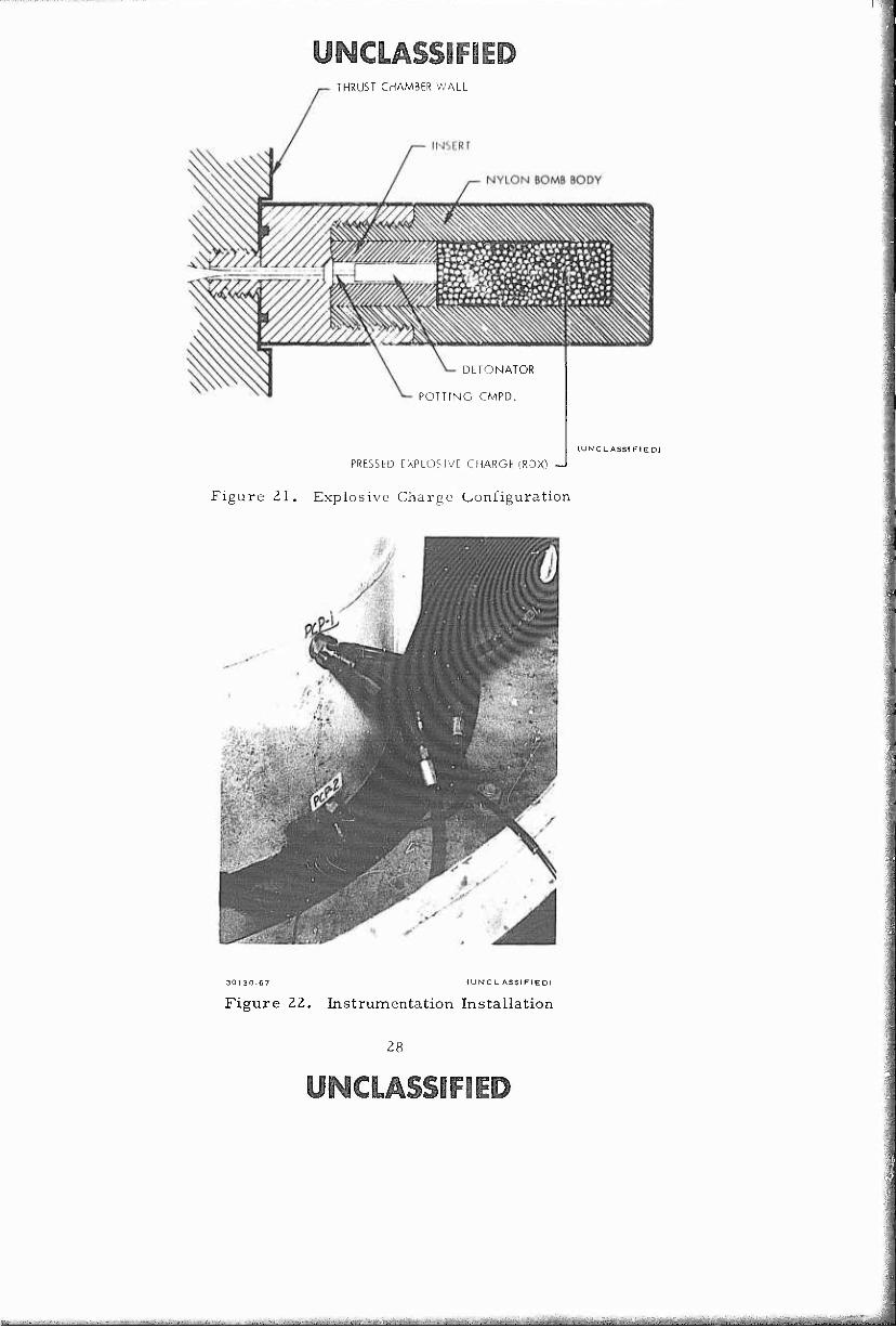
(C) Following achievement of performance levels greater than 90 percent with injector configuration No. Z, a combustion stability evaluation test series in satisfaction of paragraph 2. 7 of the contract (Modification No. 3) was undertaken. The initial test firing in the series employed a 30-gra.in (TNT equivalent) nondirectional explosive charge of the configuration shown in Figure 21. This charge was installed in the chamber wall, extending approximately 1.5 inches into the chamber at a point 3.5 inches below the propellant impingement plane. High res- ponse Photocon pressure transducers were flush-mounted in the chamber wall as shov/n in Figure 22. The timer was set to trigger the explosive charge, approximately 3 seconds after signal. The oscillograph shows the explosive charge being detonated at 2.95 seconds after start signal. Details of the test firings in the combustion evaluation test series are given in the following paragraphs.
Test VB1-593
(U) The test firing was targeted for an O/F ratio of 2.25 at the nominal total flow rate of 220 pounds per second. The start transient for this firing was typical of all prior firings showing some "chugging" at 50 cps. The chamber Photocon PcP-1 (see Figure 22) was lost 0.965 second after the start signal. This Photocon was presumably damaged in the prior firing VB1-592. The second chamber Photocon showed a chamber pressure variation of 6 psi peak-to-peak prior to detonation of the explosive charge. Low amplitude 100 cps variations were observed in the fuel injection pressure trace and 30 cps low ampli- tude variations were observed in both the oxidizer injection pressure trace and Taber chamber pressure trace. The second chamber Photocon was "lost" when the explosive charge was detonated when the Photocon amplifier became saturated. The "overpressure" generated by the 30-grain (TNT equivalent) explosive charge was estimated to be 400 per- cent. A "playback" was made of the high speed tapes of the following parameters: PFUV, PFDV, PIF. PcP-2, PcP-1, P0DV, and P10. Examination of the tape playbacks show the pressure wave surge in PIQ), PQiDV, and P0UY following the detonation and a second peak about 30 milli- seconds later. The surges in PQ)UV and P0DV are then essentially damped out and PI0 appears to follow the head-end chamber pressure fluctuations. Playbacks of PFUV, PFDV, and PIF show extreme excursions in PFDV following the detonation of the explosive charge. The fuel "cavitation" bubble is apparently being collapsed, causing a decrease in flow which results in a chamber pressure decay and high O/F ratio. As the Pc drops the fuel venturi again cavitates and flow increases, increasing Pc
rapidly and feeding back to the fuel venturi. This low frequency (40 to 60 cps) feed system controlled process continued for about 1.7 seconds without stabilizing after the explosive charge was detonated.
27
IMWlIlSflUrW-'" W:l
UNCLASSIFIED THRUST CHAMBER WALL
DLTONATOR
POTTING CMPD.
PRESSED EXPLOSIVE CHARGE (RDX) —I
Figure Zl. Explosive Charge Configuration
(UNCLASSIFIED)
(UNCL ASSI FIED)
Figure 22. Instrumentation Installation
ycmÄSSP»
_- ^ : : ; iteü^

«LÄSS1F1ED (U) Examination of the test hardware following the test firing did
not reveal any damage to the thrust chamber, injector or test stand. Examination of the interior of the thrust chamber disclosed that the ex- plosive charge had been located in a fuel-rich combustion zone which may- have contributed to the excessive overpressure. There was no evidence of increased heat transfer to the chamber wall.
(U) Analysis of the test data, including Fastax movie film coverage, indicated that the low frequency "chugging" was being driven by the fuel side of the feed system. In order to "harden" the feed system against coupling with pressure surges in the combustion chamber, the fuel cavi tating venturi flow area was increased so that the design flow rate could be obtained at a lower inlet pressure than the 230 psia required on prior tests. This had the effect of decreasing the size of the cavitation bubble resulting in an increase in fuel feed line resonant frequency from a value near the 40 to 50 cps observed to a value closer to the 150 to 190 cps calculated for the actual test system feed lines. This led to uncoupling the fuel feed system from pressure surges in the combustion chamber.
(U) A checkout firing (VB1-594) was made prior to the second com- bustion stability test to determine the effect of the increased area fuel venturi on normal operation. In addition measures were taken to protect the high response pressure transducer at the time of charge detonation. Figure 23 shows the explosive charge and Photocon location for the second combustion stability evaluation test firing. A Kistler high response pres- sure transducer (Model 616A) was mounted in the chamber head 90 degrees removed from the explosive charge location. Figure 24 is a schematic representation of the charge and instrumentation location.
Test VB1-594
(U) The test firing was targeted for an O/F ratio of 2.20 at a total flow rate of 220 pounds per second for the purpose of facility and instru- mentation checkout prior to the second combustion stability evaluation test firing. The start transient for this firing was typical showing a low fre- quency "chugging" start at 30 cps for about 0.5 second. The start tran- sient is shown in Figure 25. Both injection pressures were smooth and the chamber pressure variation (as recorded with the Kistler transducer) was approximately 7 psi, peak-to-peak. The O/F ratio achieved during the firing was slightly low (2. 12) as a result of higher than normal fuel flow. The measured performance level fell within the limits of that measured on previous firings with this injector configuration.
Test VB1-595
(U) The test firing employed a 20-grain (TNT equivalent) explosive charge which was signalled to detonate at 2.6 seconds after the start timer signal. The target run conditions were identical to test firing VB1-594; both target O/F and total flow rate were achieved. The start transient and steady-state portion of the firing prior to detonation of the explosive charge were essentially the same as test firing VB1-594. Figure 26 is a reproduction of the oscillograph (number 1) from just prior to charge detonation to 150 milliseconds after detonation. A large pressure surge can be observed in the oxidizer injection pressure trace at the time of the
UNCLASSIFIED

UNCLASSIF
Figure Z5. Explosive Charge :md Photo con Location
KISTLER
BOMB LOCATION
'CP
EXPLOSIVE CHARGE LOCATION
rCP
I- 11'u re S> l;cii;.it. i
"I I \]) I u M '■
I n >1 i-ii 11 UM;I,
ilal le-
t ion
UMCLASSIF •;.)

fo l\J kl w
m—^J-<
i
' ■' -V m^' A'vV rWK' ,\,W /«V\' ^«V r^, s.VS' ,W^V ^\V -*^
o> li^ ^ iu "j i - o rj fy i N r^ r\j wi •". rsj N M - •C CD ,>i o*i^ t»^ u ^ - c^ o . f
i i -f 3 XJ.O- ... t u,^ - O -*» J » V* tv Ui N f
I I
! I
! i
I I i I i I
! i i - i
) ) 'I I I 'f- nj »fis | i i i >' t ■"! ■ *
V^^V^^^ 1—t I > «- H 1 1 f.
t-r-rrr-r-H-rH^.
:
,.—_^.T™_^_„.___;_
3
UNCLASSIFIED
I
K ; K^ *to) «m **** ivgj
m
'V \^s|<^
i:
lVlW»r»^ »r^^wv ^l
OXID
-H—+
lO
w 'J ^
'>«»¥X "Al
I !
T—^—r
M' : M^vifciw/ '•V
Y'f*
10
I0Ü CPS TIMING
t^-T^C d-
I
l\i - O -0
OXI1') VAl <L PUililOU
I 1 J ^ L
(t,-~•Y*'(,*U'[*'^'' l»V,'
J L TT
i
'<«'/-^
/vv
(D I ( (> rt u 1U ^)i— o ■0 CDI^J O^i Ui t»
VB-I $74
I i
I I I 1 r
Figure Z5. VB1-594 Start Transie Oscillograph Reproduc
31 (The re verse side of this page i
UNCLASSIFIED
[4 niVri ittH I ■ i-fJnitiMff/'^i'iri Mi ttjil^ueiäa&MJ^iMiaSjiäM^^tt ^kii^^^^^k^äta^^^^aa^^ T-

mmmmmmmmmm ;i*W**!W'«=«!5«"W»'™^^ —-rt^mtr^w^i
UMCLASSIFIED
m
OXID
"^fsJii^rj:
>^;^:
W (•) U ^J W »-j w 1J
T "" f j tu ij IM fj ) * fc Nl fr- r- o o
DXIl) '.'Al .. HUSIIIOI I ! I I
I I M^'
VvW^VX^N*^
^ :> ■ *<i
(0 t I » I n U •0 CDI^J ^;U> fc;i-j rvJj
1 I I IM[R SIGNAI
1 VB-l 594
I '
! ! I
1 ' I 1
00 CI'S TIMING
Figure 25. VB1-594 Start Transient Oscillograph Reproduction
31 (The rcverae side ol this pa^e is blan
UNCLASSIFIED
^■lrf^1lmm,,<^Hi>atttol<iMai^*wato^.^ :^.,.^-^u^..^^^^^^^^^^^^ia^^Ariai^
*n*ww..LiMi^immmmmmm''mmm l.^|i^tllijHH4IMI|PWilMMj;ailllliWWIipw
UNCLASSIFIED
y ^r\y
*ysj\ss**sK*
1 .">,
i A ts 4 o\ i k L N 7 ^u 0 (D |NJ Ov J> & «i ro X ~ 1 V- i, w
A t» AlalE - V*\ -^
VB -1 595 OS i
1
:iLLOGRAiH 1 1
1
"FUEL ■■■1 ...
"O XID
W* ■"" "■"f5 W*" MM) t*mm v^n IHN ■m ■MI W* «^
I 1 i BOMB SIGNAL
~X J J - ! 5=ai IM«J *** Z£ s; B5 Mi SB SB 3B5 SUM
1 Bp '_ BZ SS zz
PCH
M« Si
L* ̂ Mi L M«j i. L - mm W
r i
MM MM j
|| C .S'tlW 5- ""ff HI ̂
Mi«« -
Ni id
a»
^ >.
yi-- mm
Ä* 1 7;- m ■pF: i
^ ̂ f w JL w It' . I. ■/ ■ ; ' ■,-'
■ \4 ■ . ä , ' ' A
'»-T
m •'i
«^■-^•v^/
/ 100 CPS TIMING
IO
^^^'il9JIK4fW^qft<il»4»4*M*MI««lKV|P>ll«^MMlPk«.
84.8 P5IA
P5IA
60.4 F'SIA
149.6 P5IA
149.6 PSIA!
60.4 PSIA
Figure Z6. VBl-595 Oscillograph (No. 1) from Before Charge Detonation to 150 msec After Detonation
33
UNCLASSIFIED
^^^^^■ra-ai^iiii^^^^tf ^^^r;^^.^^^

SÜBP WwW^Pl'H^Prw^P'r tfffKmmmiMi wwiiHUiiiMmHii ums IWBIIWIIWPWIPW^IWVWPWIPmiWTOPII* liMHWIWWHmiHII, 1,111.1111 ..Ulm
UNCLASSIFIED explosive charge detonation and recovery to normal operation occurs within 100 milliseconds. The playback of the high speed tape showing the Kistler transducer, Photocon transducer, and X-X accelerorneter for the same time period is rcprcduced as Figure 17. Both the Kistler and the Photocon pressure transducers show pressure surges of 150 psi above operating pressure. This is equivalent to a Z5Ö percent "over- pressure. " Figure ^7 shows that the complex acoustic wave which was generated has been damped out in 15 milliseconds and, although some in- dication of the 40 to 50 cps test plumbing resonance still remains, the feed system recovery is essentially complete within 40 milliseconds.
(UNC l. AS 51 F1EOI
Figure Z7. Test Vßl-595, Oscillograph of high Response Trans- ducer Showing Explosive Charge Detonation
3 -1
UNCLASSIFIED
.. .. 1 .■■--■^■■v-.^-^...- ,; .V.i,— .__: . >-'l:-:,ni',.-- ■ --^-^i-t!_; ^ , , ,_ . TÜf^M

UNCLASS -ED SECTION III
CONCLUSIONS AND RECOMMENDATIONS
(U) The conclusions reached while performing the program of experi- mental engine firings are summarized as follows:
1) The centrally located, coaxial injector rated at Z50, 000 Ibf thrust operated at 50, 000 Ibf thrust is dynamically stable when subjected to explosive charges which produce "over- pressures" in excess of 200 percent of the normal operating pressure.
2) The scaling concepts used to scale the LMDE coaxial injector over a 25-to-t range appear promising.
3) High thrust injectors may be designed with a minimum of precision tolerances for fabrication using conventional industrial fabrication techniques and will produce acceptable performance.
(U) The following work should be undertaken for the purpose of obtain- ing basic engineering data which will allow scaling of the coaxial injector design for use in multimillion-pound-thrust liquid rocket engines of maxi- mum cost/effectiveness.
i) Engine testing at the rated thrust level (250, 000 Ibf) to demonstrate performance and inherent dynamic combustion stability.
2) Experimental testing of low-cost combustion chamber liners to determine the applicability of such materials for very large rocket engines. At least two candidate materials (SOC-CO K742HT and Dow-Corning 93-069) are now avail- able. Testing of these materials in a 40-inch-diameter chamber would allow a fair assessment of the fabrication problems which might be encountered in full-size thrust chambers.
3) Engine testing of a low-cost LITVC to delineate problems, i. e. , (i) protection of the injection valve seat from the hot, expanding combustion gases, and (2) behavior of the low- cost nozzle insulation in an oxidizer- or fuel-rich combust- ion environment.
«USSlFiJ 35
Jäk ^L
■"" '■■ " ■
,■■■■•■■■■.-.;■■.■•■
. ■
UNCLASSIFIED APPENDIX I
FACILITIES
The test program was carried out using the facilities at the Vertical Engine Test Stand (VETS), at the TRW Capistrano Test Site (CTS). VETS has four vertical engine test stands, Al, A2, Bi, and B2 each currently- rated at 50, 000 pound thrust level. Stands Al and A2 are equipped with 2:1 diffuser, steam ejector systems which permits choked-flow operation of LMDE at chamber pressures as low as 8 psi. Stands Bl and B2 are utilized for sea-level testing.
(U) The test stand has four propellant run tanks, viz. : two 1000- gallon fuel nks (750 psi working pressure), two 1000-gallon oxidizer tanks (750 psi working pressure). Tankage, valving, and lines are such that they can be interconnected for extended duration engine tests. Safety features of the propellant feed system include pressure relief valves and burst diaphragms. The VETS has its own nitrogen cascade system which is used for fuel and oxidizer pressurization and engine purges.
(U) Test stand Bi (outboard sea-level position) was utilized for the 15 test firings in the test program. The modifications to the Bl position required to carry out this program have been described previously. Figure 28 is a schematic representation of the propellant feed system from the run tanks to the fire valves on the engine. Cavitating Venturis were installed in both the oxidizer and fuei lines as shown in Figure 28. The oxidizer venturi inlet was located approximately 10 feet upstream of the oxidizer fire valve while the fuel venturi inlet was approximately 4 feet up- stream of the fuel fire valve. Both fuel and oxidizer lines were equipped with high-point bleeds which dumped overboard. Filters were not used in the propellant feed system.
(U) The pressurization system for each of the run tanks is not shown in the schematic. As noted previously, each tank was pressurized from a mobile high-pressure GN-, storage trailer through large diameter piping and Series 400 Grove pressure regulators.
UNCLASSIFIED 36
■tttLJJM . i ■ : : ■■ ■■■/ -■
pttyB^M^MWR^^'-''^^^^ " " ■" ■' ■,■""■■•■■T■- :;-~T--
y^OLÄSSlFED
m tu Ui
>—INxHi^
(O
W
T3 u 0)
ß
i—(
£X 0
0
o
0) w a)
a, 0)
0)
u
00
u
M •H
OI^OLHSSlFlEi 37

^»■^fWPfllWjBfP mmmmim mimmmmimiii'mim WÜBHPWPPWW^SWSS IH«*,«ii|!flP!IPIWWWllljp-WiJ'Jl.l«'JSJB-llSV-li
UNCLASSIFIED APPENDIX II
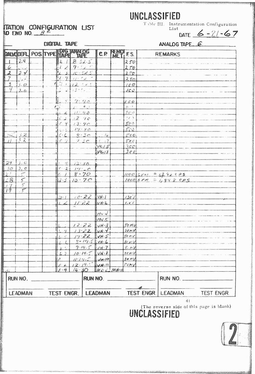
INSTRUMENTATION
(U) Multiple inetrumentation was maintained on all critical pressure parameters. The instrumentation required throughout the program is shown in Table II. Table III presents the instrumentation configuration list for test firing VB 1-594. Dual measurements were made of head-end chamber pressure and downstream pressure, as well as oxidizer and fuel injection pressures. Pressure measurements were obtained with Taber-Teledyne bonded strain gage transducers. These transducers were dead-weight calibrated in the Capistrano Test Site (CTS) Metrology Laboratory prior to initiation of the test firing programs.
(U) Flow rate measurements were made with turbine-type flowmeters manufactured by Potter (fuel side) and Fischer-Porter (oxidizer side). Pro- pellant temperatures were measured in the flowmeter sections for density determination. Figure 29 shows the instrumentation locations utilized throughout the program's test series.
(U) Chromel-alumel thermocouples were attached to the external surface fo the thrust chamber as shown in Figure 30. The thermocouples were only used as an indication of local overheating and were not intended to be used for heat flux measurements.
EXPLOSIVE CHARGE LOCATION
40.0-
CH-1.2 IANDKISTLER)
TO FLOW CONTROL VENTURI (POUV, PODV)
ACCELEROMETERZ-Z
^_TO FLOW CONTROL VENTURI
EXPLOSIVE CHARGE LOCATION
Figure 29. Explosive Charge and Instrumentation Locations
Figure 30. Thermocouple Identification and Location
38
.. :>..;.■,f.,.|.1i-.-r iYiirrinrttftiMiM'^m^'^ ^^^**^^mmr****.^^.~

mmü nn mm wm
UNCLASSIFIED Table II. Test Instrumentation Requirements
Symbol Parameter Ran ge Osc. Strip
Chart
wox N204 0-1000 gpm X X
cLf UDMH Flow 0-1000 gpm X X
Tox NpO . Flowmeter Temp. 0-150 DF X
Tf UDMH Flowmeter Temp. 0-150 DF X
PTox NpO, Ullage Pressure 0-500 psi X
PTf UDMH Ullage Pressure 0-500 psi X
Pouv N2O4 Cavitating Venturi Inlet Pressure 0-500 psi X X
Pfuv UDMH Cavitating Venturi Inlet Pressure 0-500 psi X X
PIO-l.Z N?0 . Injection Pressure 0-250 psi X X
PIf-i, 2 UDMH Injection Pressure 0-250 psi X X
Pch-1,2 Chamber Pressure, Head- End 0-100 psi X X
Pcd-1,2 Chamber Pressure, Downstream 0-100 psi X X
Tch-1, -8 Chamber Temperature 0-2000oF X
Pcp Chamber Pressure, Photo con 0-1000 psi X
ACCELZ-Z Accelerometer 0-300 g X
Pcp-2 Chamber Pressure, Downstream (Photocon)
.- (UNCLASSIFIED)
(U) Accelerometers were mounted on the injector to indicate vibra- tion levels in all three planes. Both Photocon and Kistler high response pressure transducers were used during the test program. The Photocons used were model 352A, water-cooled, with flame shield The Kistler transducer employed on firings VB1-594 and VB1-595 - as a model 616A which is water-cooled.
«LMFiB 39
jtThe reverse side of this page is blank)
— Ci^_: y. ■ i . ^niiiiiiiin'iiimiiiiiiiiiMiiiTiiii

uiiiwwj^ww^'WWiw^pwwy^ "■■■-^m^-^vr'^'^-^ ._., ..._. .^
RUN NO \r_
PAGE /
X_-^i vv INSTRUMENIATiON
HEAD END NO ä
OF _J_ DURATION SEC-
mimmmmmmim
- WWWWilliWliwuiW!WJJPW^ i.li*»ai.i>iuiiu>u<>i.<
UNCLASSIFIED
M> END WO tf2-
T ible III. Instrumentation Configuration List S ^ S
DATE <g> ~?J ~£> y
ANALOG TAPE—^
(The reverse side of this page is blank)
UNCLASSIFIED
«».ttitttei.,,,^^^^a«w.^aa^j«a^a4a^^^ ^...- ......... .... ....,:.Aa&tfc.tA^„t>iJt(Mll

fmmm 1fllll!^i^mm'.^««'h'j^jywAmimmhMßmmH¥&^
RUN NO
PAGE__ OF DURATION
INSTRU^Ef^mnON CONRGURA1 HEAD END NO. &£.
SEC OGTIAL
I Vt- ■, reiWWiMrNi'Tl-fntWaMfllrM^liff^ ■ . ^»rf^^^-^^^-^^^^a^^^^. ^Amt^^

pgwswj. mmii.mummmmmm>fm.m.J. ".< ^m^mmmm.lfm*mmm*m^mwmm>m™mw W**wwwmm!»™timwimmi»mmwwMijm^!imium>mk*mTB
MCUSS1F1ED SON CONRGURATION UST :ND NO. SZ
Dl^mL TAPE
Table III. Instrumentation Configuration List (Continued)
DATE
ANALOG TAPE
(The reverse side of this page is blank)
VL
'S I
wfea,iM'tri«iliiiiti)-i»i6Mat iB^^^*^Mii-'^^'J-^'""^rTnMMftfiit^
mnvim*. upppi ■■ -^ gpntpmg ,r?I?i»^^f^?^?«^WW«?^'H«S^W7Pra^^ ™"".-1. '"^^lilWRlffi" T1yi.TV,i.J..,,vv-^^.,v,,,,B,s„i^Tlvr,- <i^htpii M w^m'i 1
UNCLASSIFIED APPENDIX III
ENGINE PERFORMANCE ANALYSIS PROCEDURES
(U) This appendix describes the data reduction procedures used to reduce the raw performance data. All raw performance; data were re- corded on digital tape and reduced^- by means of the SDS 935 computer on a run-to-run basis.
(U) In the absence of thrust measurement the engine performance was characterized by the use of characteristic exhaust velocity. The characteristic exhaust velocity was computed by:
C* o tbo W,.
(1)
where
C* - characteristic exhaust velocity, ft/sec
P = nozzle stagnation pressure, psia
■sec ) e = gravitational constant (32. 137 lb -ft/lb,. Bo 5 v m f
WV = total propellant weight flow, lb /sec t m
The combustion efficiency (rip^) was computed by dividing the C* com- puted from the equation by the theoretical frozen characteristic exhaust velocity at the appropriate test nozzle stagnation pressure and oxidizer- to-fuel ratio. Figure 31 shows the variation of theoretical frozen C* for several nozzle stagnation pressures and O/F ratios. The values used in constructing Figure 31 are taken from Reference 2 plus supplemental calculations for 50 and 65 psia.
(U) Each of the parameters within the C* equation was computed as follows. The nozzle stagnation pressure (P ) was computed from the ratio of nozzle stagnation pressure to chamber str.tic pressure (Pccj) as determined from Equation (2).
CTS "Quick Look" and "Real Time" Performance Analysis Program, TRW Memorandum 65. 9731. 9-124, dated 30 August 1965. 2 Theoretical Performance of N^WUDMH, TRW Memorandum
9732. 11. 65-177, dated 7 October 1965.
UNCLASSIFIED
i^^>"ai',''i°^'^itimfmtii-i ..^^■y^^^,..^
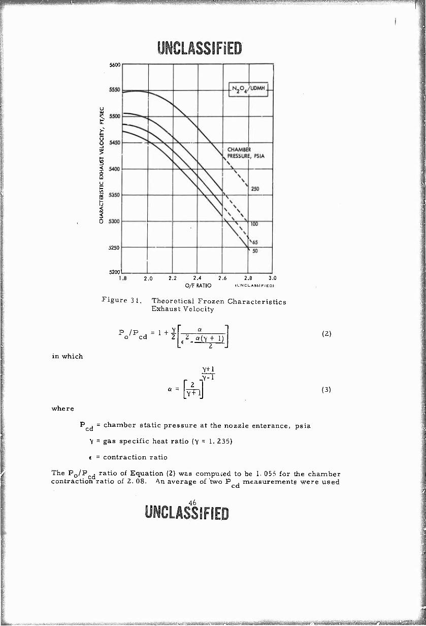
wmmmmmmmmmm |JPP|g|JJ^|||||||P]Pg)|JW?»p^^
5600
U UJ
if e
<
y
t3
5250
5200 L
UNCLASSIFIED
2.0 2.2 2.4 2.6 2.8 3.0 O/F RATIO (i-NCLASS(FIED)
Figure 3 1. Theoretical Frozen Characteristics Exhaust Velocity
in which
where
P /p = 1 +1 o cd 2
2
-N V+l
(2)
(3)
P j = chamber static pressure at the nozzle enterance, psia
V = gas specific heat ratio (y = 1. 235)
e = contraction ratio
The P0/P , ratio of Equation (2) was compuced to be 1. 055 for the chamber contraction ratio of 2. 08. An average of two P , measurements were used
cd
46
«LßSSJFIED
. ■■■:.: ... ■ ..J-'M.. . .-M - rrrrnrmr .n- " . ■ V^VMliliilfriWiltemiTiMl^llir
Fr,j.,^iy^.w..P^~.lMK'i*ri-.-ii;i|i^
UNCLASSIFIED to compute P0. The propellant flow rates were computed from the fre- quency output of the flowmeter, the calibration factor, and the propellant densities based on the measured line pressure and measured propellant temperatures. No change in flowmeters was required throughout the test program.
(U) The nozzle throat area was computed from the average of nu- merous throat diameter measurements taken prior to the start of the test program. Measurements taken at the conclusion of the test program indi- cate less than a 0. 02 percent change in throat diameter. The local gravi- tational constant at the CTS (32. 137 lb -ft/lbf-sec ) was employed in Equation (1). m t
47
UNCLASSIFIED
IK -_:-■-■■'- |-|^[h•^^l|fr^^l^'^hS;AUai^'<^^*'-^■^■'^'"i^•^t•^■^3•■ J -■,' ' ^ •' '"^^ ^ '-^"■''■'^'"^~ ■

rc^.,^ r, i. ii ii i i.uijiiiijiiMijiiii.nmriiTTiTmmi—i. I. i.Ll I II .. .1 "' .... ^^'^~"
UNCLASSIFIED APPENDIX IV
PERTINENT REMARKS—PERFORMANCE EVALUATION TEST FIRINGS
(U) This appendix contains pertinent remarks and observations for each test firing in each of the two Performance Evaluation Test Series.
TEST SERIES NO. 1
(U) VB1-581: The initial test firing was targeted at a O/F of 2. 25 and 220 pounds per second total flow rate. There was no significant temperature rise on the external thermocouples and inspection of stand and TCA following the firing did not disclose any abnormal conditions. The rubber pintle tip (Dow-Corning 20-103) appeared to be essentially unmarked. The chamber Photocon showed a random pressure oscillation of 6 psi (peak-to-peak) just prior to shutdown. The chamber pressure did not reach a stabilized value during the 3. 2-second firing duration. The chamber Photocon was damaged during the sequenced GN^ purge following shutdown.
(U) VB1-582: The second test firing in the initial test series was targeted for an O/F ratio of 2. 6 at 220 pounds per second total flow rate. The test firing duration was increased from a nominal 3. 0 seconds to a nominal 5. 0 seconds to allow for acquisition of stabilized data. The mix- ture ratio obtained in the test firing was slightly low (O/F = 2.53) due to a higher than normal Oxidizer tank nitrogen regulator pressure drop. The chamber Photocon showed a random pressure oscillation of 7 psi (peak-to-peak) during the steady-state portion of the firing. The chamber pressure reached a stabilized value during the last 2 seconds of the 5. 3- second firing. Again there was no significant temperature rise shown by the external thermocouples.
(U) VB1-583: The test firing target conditions were an O/F ratio of 2. 8 at a total flow rate of 220 pounds per second. The O/F ratio and total flow rate achieved during the firing were both about 2 percent low with no significant changes in engine characteristics from the previous firing. The chamber Photocon showed a 6 psi peak-to-peak variation during the steady state portion of the firing.
(U) A thorough examination of the test stand and test hardware was made following the third test of the first test series. The silicone rubber pintle tip was in excellent condition following 14 seconds of firing and exposure to raw oxidizer during system blowdown tests. The heat-sink thrust chamber showed niarkings typical of that experienced during a LMDE firing. No external heat markings were observed on the thrust chamber.
48
UNCLASSIFIED
^t.^^i^f^-^..^..^^^^.rt.to|[|Y||.||r|rn| „, „„M^LY Ilin H^^^^tMKftiritll^^

JWM^W^WWW*«»"^»'^'"-»'™™^'!""'"«'»^ HI« I II |I|I1WB ■IW»IWB^WI»W»WB—PWmWW<
€(eOTP[l[^¥OM
(U) The fourth, fifJi, and sixlh firings of test series No. 1 were made following a seriei of difficulties with the shutdown timer and mal- function of oxidizer lead interlock microswitch. Tue timer had to be replaced and was reset to provide a 4. 5-second test firing duration.
(U) VB1-584: This test firing was targeted for an O/F ratio of 2. 0 at a total flow rate of Z20 pounds per second; both conditions were achieved during the firing. The chamber Photocon showed a 6 psi peak- to-peak fluctuation during the steady-state portion of the firing.
(U) VB1-585: This firing was targeted for an O/F ratio of 2. 25 at a total flow rate of 242 pounds per second to investigate the effect of in- creased total momentum. The O/F ratio achieved was slightly low and total flow rate slightly high. There was no increase in chamber pressure fluctuations and the performance was approximately 1. 5 percent higher than the baseline firing (VB1-581).
(U) VB1-586: This firing was targeted for an O/F ratio of 2. 53 (duplicating the O/F ratio of VB1-582) at a 10 percent increase in total flow rate. The chamber pressure Photocon showed a 7 psi (peak-to-peak) fluctuation. As a result of malfunction of the shutdown timer the test firing duration was 9- 5 seconds. This failure was similar to that experi- enced during the electromechanical checkout prior to test VB1-584. The external thermocouples indicated a temperature of 304 F at the throat just after shutdown with a soak-back to 409oF at 8 seconds after shutdown. The chamber pressure dropped approximately 1. 5 percent during the last 3 seconds indicating internal wall temperatures high enough to cause ther- mal expansion of the throat. Examination of the hardware did not disclose any abnormal condition. The silicon rubber pintle tip was intact and the chamber showed the typical markings. The external paint at the throat section showed evidence of the high temperature.
TEST SERIES NO. 2
(C) VB1-587: The initial test firing in test series No. 2, following injector modification, v/as targeted for the design conditions of an O/F ratio of 2. 25 and a total flow rate of 220 pounds per second. The mixture ratio achieved during the firing was approximately 4 percent low. The performance increased more than 10 percent over that obtained with the initial injector configuration at the same O/F ratio. The chamber pres- sure Photocon showed a 5. 0 to 7. 5 psi peak-to-peak variation.
(U) VB1-588: This test firing was targeted for an O/F ratio of 2. 55 at a total flow rate of 220 pounds per second. The mixture ratio achieved was 2 percent low (O/F = 2. 50) and the weight flow rate was slightly more than 1 percent high (223. 0). The chamber Photocon pressure transducer showed a 5 to 10 psi fluctuation throughout the steady-state portion of the firing at 40 cycles per second. The performance increase at higher mixture ratio for injector configuration No. 2 was somewhat less than the increase achieved at the lower O/F ratio. ,
CONFIDENTIAL
..-■»ii-^^-a««^:/^^^^.^^»^^ .--■...■...-.■ . .■■ ■;....^.-. .,-..„■ .....j,....^..^...^.^ ^.. ■■i^;.^.1fLt:^.w.t-3-- ...■
WBPPIP^waiswpwPwwniwiwwpwH TCiP«i9niiHimuPvPVUiJi^iiJiuijiiUMii^w.w^
(SOMPQPg^TDAt
(C)_ VB1-589: This test firing was targeted for an O/F ratio lower than design (O/F = 2. 00) at the nominal total flow rate. The highest com- bustion efficiency (95. 5 percent of theoretical frozen C*) was achieved during this firing. This is nearly 12.5 percent higher than that achieved at a comparable O/F ratio with injector configuration No. 1. The cham- ber Photocon showed a variation cf 5 to 8 psi (peak-to-peak) throughout the test firing.
(U) VB1-590: Test firing VB1-590 was the first test of injector configuration No. 2 targeted for 110 percent of ';he nominal flow rate to investigate the effect of total momentum level. The target O/F ratio was 2. 00. The performance level decreased approximately 1 percent when -bompared with firing VB1-589. The chamber pressure oscillation was nearly identical with that of VB1-589 showing some feed system disturb- ance of 50 to 60 cycles per second.
(U) VB1-591: The targeted O/F ratio for this firing was 2. 25 at 110 percent of nominal flow rate to investigate the effect of total momentum level at a second momentum ratio. Again, a 1 percent decrease in per- formance level was observed. The chamber pressure oscillations were 5 psi (peak-to-peak) as recorded with the flush-mounted Photocon.
(U) 'VB1-592: The targeted conditions for this firing were an O/F ratio of 2. 25 at a total flow rate of 198 pounds per second. The firing was terminated 2. 6 seconds after fuel flow initiation when there was an instrumentation malfunction which indicated low oxidizer flow. No data was taken as the chamber pressure had not stabilized.
50
@2)KW^¥DAL
.■,Xm^..: . .-;r..-1.-.~- -, ■.■;. , . iJrturt i iTrii 'ini ri MTI af aviif ._.->>.-#-,'.-. ,... ■.-..: At'Jnail&UWUl'Jil
RPippmn«iii.ii«iuiPiLi«iL|i)nipj|Piiiiiiiiwu>i!>i j|iMIJj.wWii,.;|iMMa».'*i|WWIIWIWPWii^
Security Classification
DOCUMENT CONTROL DATA R&D fSecurKy cInMsitn uliun ot litte body ot abslritcl and rndexinf} Bnnotitltnn must br entered when the all rep:,,i is c la* sitledl
I ORI.-.INATIN G ACTIv/iry (Corporate author)
TRW Systems Group
Rj;PORl.SECuniT.Y CLASSIFICATION
Coniidential 2b GROUP Gr 4
3 flEPORT TITLE
Advancement of Injector and Thrust Chamber Technology
* DESCRIPTIVE NOTES (Tvpe ot itporl and tncluaive doloM)
Technical Report, 1 March 1967 to 30 June 1967. 5 *UTHORrSJ fL«tl n«m», (/riln«m». Initial)
Voorhees, G.A., Jr.
6 REPO RT DATE
December 1967 '7« TOTAL NO OF PACES 7b NO OFPCPa
49 Qfl COKTRACT OH GRANT NO
AF04(6 11)-11382 M h PROJCC V NO '
9« ORIGINATOR'S REPORT NUMBERfSj
AFRPL-TR-68-46
9fc OTHER REPORT NOfSJ (Any other numbera that may be aaalinad this report)
io <IVA iLABiLiTY/LiMiTATioN NOTICES iiiaddition to sccunty requirements which mulst be met, this document is subject to special export controls and eaqh transmittal to foreign governments or foreign nationals may be giafa^onl^ vtfj^tyior approval of AFRPL (RPOR-STINFO), Edwards,
SUPPLEMENTARY NOTES | 12 SPONSORING MILITARY ACTIVITY
Air Force Rocket Propulsion Lab- oratory, Edwards, Calif. 93523
'his report covers an experimental test program to determine the scalability of the LMDE centrally located, coaxial injector to much higher thrust levels than previously tested. A 250, 000 Ibf thrust, 300 psia chamber pressure Thrust Chamber Assembly (TCA) was fabricated and tested at a reduced thrust level of approximately 50,000 Ibf thrust. The TCA design consisted of a centrally located coaxial injector, based upon the LMDE design, and heat sink com- bustion chamber. Performance levels in excess of the contractual requirements were achieved. Dynamic combustion stability test firings, employing nondirectional explosive charges, verified the combustion stability characteristics of the coaxial injector.
DD FORM 1473 CLASSIFIED Security Classification
r- ••■■-• rt^^^MLil*!^--****^***,. i r'tiViWri^^i^vi^r-iiiMii'iilfrteiirn-iviUiii rn irtimrilrtffln'filfriWrWKii'ild-'inr T "-*'-^*J--
mmmmKm^KmgmH^^!':. ^'?!g'gg!^gwgpwgwHg^g^l|g^P8W^W ■WMWMIPRWJWIW»
COE^^D^flMITDAL UNCLASSIFIED
becuvity Classification
KEY WOHDS
liquid propellant engine
injection
stability demonstration
low cost
ROLE: WT ROLE WT ROLE WT
INSTRUCTIONS 1. ORIGINATING ACTIVITY FntPr the name and address of the contractor, subroniractor, grantee, Department of De- fense activity or othfr orRantziition (corporate author) issuing the report.
2a. REPORT SECURITY CLASSIFICATION: Enter the over- all security classification of the report. Indicate whether "Restricted Data*' is included. Marking is to be in accord- ance with appropriate security re^ulntions.
2b. GROUP. Automatic dow.-^radin^ is specified in DoD Di- rective 5200. 10 and Armed Forces Industrial Manual. Enter the Kroup number. Aiso, when applicable, show that uplional markings have been used for Gruiip ,1 and Group 4 as author- ized.
3. REPORT TITLE; Enter the complete .eport title in all capital letters. Titles in all cases should be unclassified. If a meaningful title cannot be selected without classifica- tion, show title classification in all capitals in parenthesis immediately following the title.
4. DESCRIPTIVE NOTES: If appropriate, enter the type of report, e.g., interim, progress, summary, annual, or final. Give the inclusive dates when a specific reporting period is cv ered.
5. AUTrlOR(S): Enter the name(s) of authors) as shown on or in the report. Entei last name, first name, middle initial. If military, show rank »nd branch of service. The name of the principal i »thor is an absolute minimum requirement.
6. REPORT DATL: Enter the date of the report us day, month, year, or month, year. If more than one date appears on the report, use date of publication.
7a. TOTAL NUMBER OF PAGES: The total page count should follow normal pagination procedures, i.e., enter the number of pages containing information.
76. NUMBER OF REFERENCES: Enter the total number of references cited in the report.
8«. CONTRACT OR GRANT NUMBER: If appropriate, enter the «pplicable number of the contract or grant under which the report was written.
86, 8c, fit 8d. PROJECT NUMBER: Enter the appropriate military department identification,,such us project number, cubprojcct number, system numbers, tflsk number, etc.
9«. ORIGINATOR'S REPORT NUMBER(S): Enter the offi- cial report number by which the document will be identified and controlled by the originating activity. This number must be unique to this report.
96. OTHER REPORT NUMBER(S): If the report has been assigned any other report numbers (either by the originator cr by the sponsor), also enter this number(s).
10, AVAILABILITY/LIMITATION NOTICES: Enter any lim- itations on further dissemination of the report, other than those
imposed by security classification, using standard statemente su.'h as:
(1) "Qualified requesters may obtain copies of this report from DDC "
(2) "Foreign announcement and dissemination of this report by DDC is not authorized."
(3) "U. S. Government agencies may obtain copies of this report directly from DDC. Other qualified DDC users shall request through
(4) "U. S. military agencies may obtain copies of this report directly from DDC Other qualified users shall request through
(S) "All distribution of this report is controlled. Qual- ified DDC users shall request through
If the report has been furnished '.o the Office of Technical Services, Department of Commerce, for sale to the public, indi- cate this fact and ep|er the price, if known.
11. SUPPLEMENTARY NOTES: Use for additional explana- tory notes.
12. SPONSORING MILITARY ACTIVITY: Enter the name of the departmental project office or laboratory sponsoring (pay* mg .'or) the research and development. Include address.
13 ABSTRACT: Enter an abstract giving a brief and fac'ual bumrrrarv uf the document indicative of the report, even though it may also appear elsewhere in the body of the technical re- port. If additional space is required, a cont'.nuutiun sheet shall be attached-
It is highly desirable that the abs*ract ol classified reports be unclassified Each paragraph of the abstract shall end with an indicalmn of the military security classtficatior. of the in- fotmalion in the paragraph, represented as (TS). (S), (C), or (U).
Then- is no hmitulion on the length of the abstract. How- ever, the suggested I'.-ngth is from 150 to 225 words.
14. KEY WORDS: Key words are technically meaningful tenna or short phrases that characterise a report ana may be used as index entries for cataloging the report- Key words must be selected so that no security classification is required. Idcnti- fiers, such as equipment model designation, trade name, military project code name, geographic location, may be used as key words but will be followed by an indication of technical con- text. The assignment of links, rules, and weights is optional.
«LASSIFIED Security Classification
CONFIDENTIAL (This page is unclassified)
,.-^r^^.^l:^^u>lL^^'j^^^Jlr^Lll,\^ ^aMhaut3C> r i -pi-i«fi-ini,f,ii.'ai'iViW-MilW1iiiii -^■J--^^•-■