Embed Size (px)
Citation preview
To: All Vendors Bidding on The College of New Jersey Heat Recovery Steam Generator (HRSG) Replacement Project
From: The College of New Jersey
Date: June 19, 2019
ADDENDUM NO. 1 ISSUE DATE: June 19, 2019
REFERENCE: The College of New Jersey Heat Recovery Steam Generator (HRSG) Replacement Project Bid No. AB190035
Date of Original Bidding Documents: June 3, 2019
INTENT: This Addendum forms a part of the Contract Documents and modifies the original Bidding Documents and Prior Addenda if any, as identified above. Acknowledge receipt of this Addendum in the space provided on the Bid Form. Failure to do so may subject Bidder to disqualification.
INSURANCE REQUIREMENTS
The limits of liability for Workers Compensation/Employer’s Liability insurance in the Contract General Conditions should read as follows:
(c) Workers Compensation/ Employer’s Liability. Worker's Compensation Insurance applicable to the laws of the State of New Jersey and other State or Federal jurisdictions required to protect the employees of the Contractor and any Subcontractor, sub-subcontractor or supplier who will be engaged in the performance of the Contract. The certificate must so indicate that no proprietor, partner, executive officer or member is excluded. This insurance shall include Employers’ Liability Protection with a limit of liability not less than one million dollars ($1,000,000) bodily injury, each occurrence, one million dollars ($1,000,000) disease, each employer, and one million dollars ($1,000,000) disease, aggregate limit.
REVISED SPECIFICATIONS Remove Specification Section 235800 – Heat Recovery Steam Generator (HRSG) and replace with attached Specification Section 235800 - Heat Recovery Steam Generator (HRSG) Rev: B and is included as part of the contract documents.
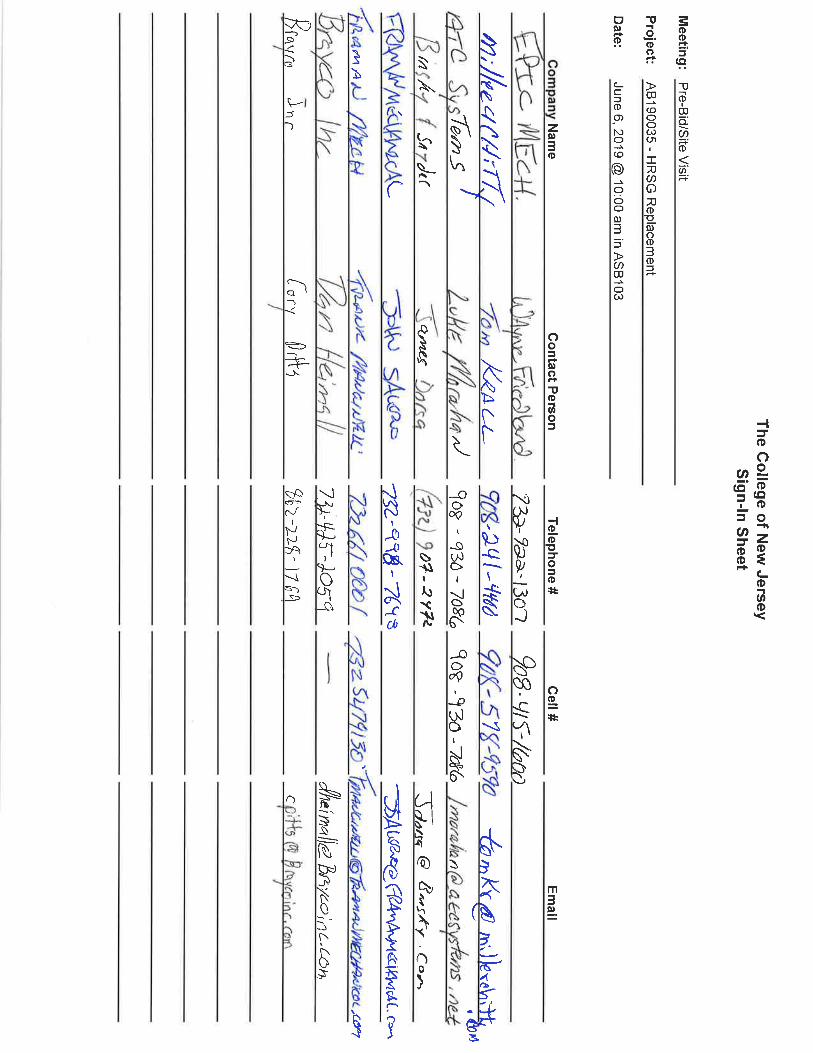
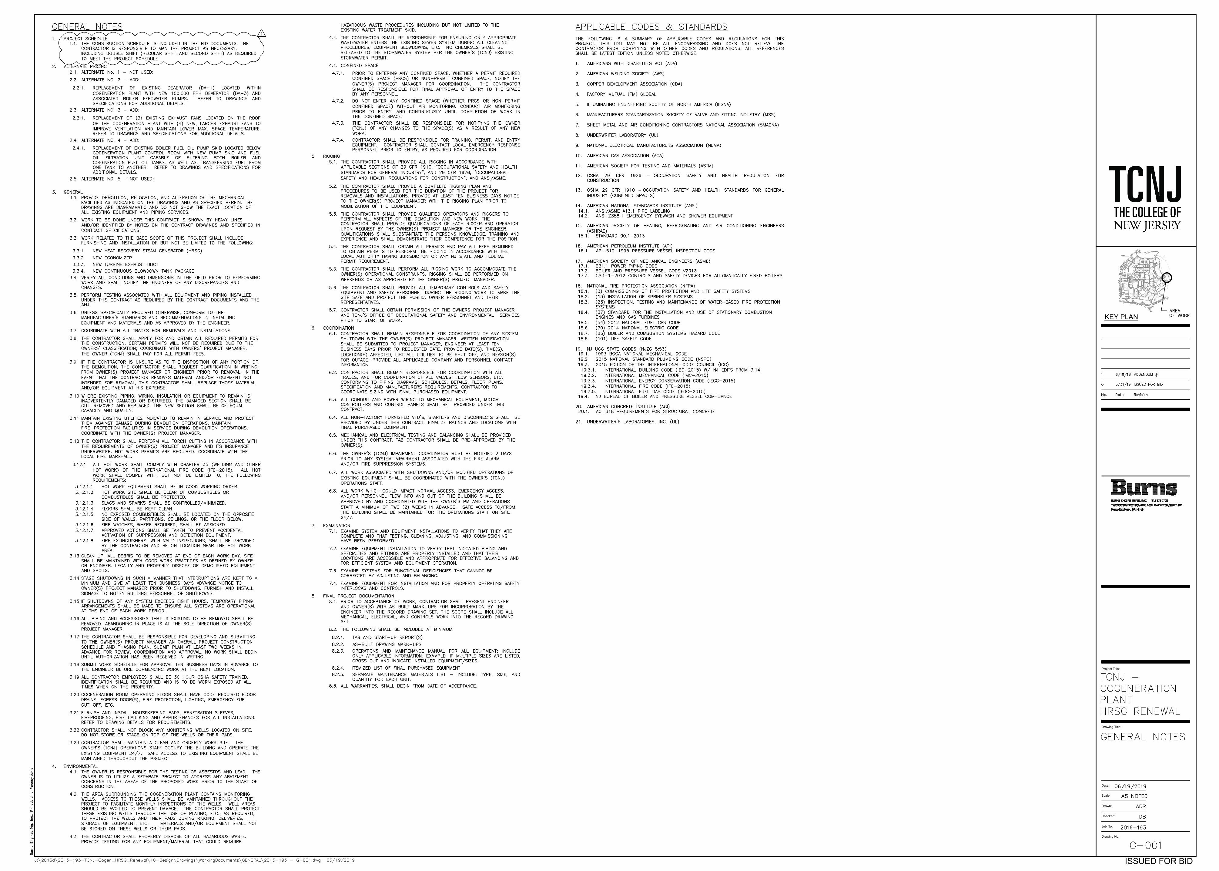
DRAWINGS Drawing No. G-001 – General Notes dated 6/19/19 Addendum #1 is attached and is included as part of the contract documents. Sketch SKM-1 – Proposed Laydown Area dated 6/19/2019 is attached and is included as part of the contract documents. Attachments: Specification Section 235800 – Heat Recovery Steam Generator (HRSG) Rev: B Drawing No. G-001 – General Notes Sketch SKM-1 – Proposed Laydown Area Pre-bid sign-in sheet END OF ADDENDUM NO. 1
Burns Engineering, Inc. The College of New Jersey HRSG Renewal Rev: B
HEAT RECOVERY STEAM GENERATOR (HRSG) 235800 - 1
SECTION 235800 – HEAT RECOVERY STEAM GENERATOR (HRSG)
PART 1 - GENERAL REQUIREMENTS
1.1 GENERAL
A. This specification covers the minimum requirements for the construction features, materials,
fabrication, inspection, and preparation for shipment of "O-type" (Slant style) shop-assembled,
Heat Recovery Steam Generator (HRSG) and associated equipment complete with all necessary
appurtenances, controls and auxiliary equipment mounted to the maximum practical extent
(allowed by shipping clearances) as an integral unit on a steel base so as to make a complete
self-contained assembly.
B. The equipment will generate high pressure steam to be utilized for heating and cooling of The
College of New Jersey’s campus in Ewing, NJ.
C. The HRSG is located indoors in an existing cogeneration facility located at 2000 Pennington
Road, Ewing NJ.
D. Refer to Appendix A for Gas Turbine Data
E. Refer to Appendix B for site conditions.
F. Refer to Appendix C for overall plot space and available footprint for equipment specified
herein.
G. Refer to Appendix D - Volumetric Composition of the Turbine Exhaust Gas for the Existing
Solar® Taurus T60-7300
H. Refer to Appendix E - Energy Recovery International (ERI) drawings for Heat Recovery Steam
Generator (HRSG)
1.2 CODES AND STANDARDS
A. All work and materials furnished will conform to the highest industry standards for material and
workmanship, and shall be designed and fabricated in accordance with, but not limited to:
1. ANSI American National Standards Institute
2. ASME American Society of Mechanical Engineers
- Boiler Pressure Vessel Code (BPVC) Section I
- Boiler Pressure Vessel Code (BPVC) Section II
- B31.1 - Power Piping
- PTC 4 - Performance Test Code Fired Steam Generators
3. AWS American Welding Society
4. ASTM American Society for Testing Materials
5. AISC American Institute for Steel Construction
6. IBC International Building Code
7. SSPC Structural Steel Painting Codes
Burns Engineering, Inc. The College of New Jersey HRSG Renewal Rev: B
HEAT RECOVERY STEAM GENERATOR (HRSG) 235800 - 2
8. NFPA National Fire Protection Association
- NFPA 85 – Boiler and Combustion System Hazards Code
9. OSHA Operators Safety and Hazards Association
B. All equipment shall comply with federal and state laws and regulations governing the location
where the equipment is to be installed.
1.3 QUALITY ASSURANCE
A. It is the responsibility of the Contractor and equipment Vendor to ensure that the completed
work, and that of their sub-vendors, conforms in all respects with this specification including
the applicable codes and standards. If a conflict within this specification or between this
specification, the inquiry or purchase order, data sheets, drawings, and other supplemental
specifications is discovered, the Contractor and/or equipment Vendor shall identify the conflict
in writing for clarification by the Owner.
B. The equipment shall, as a minimum, be in strict compliance with the requirements of this
specification and shall be the manufacturer's standard product unless specified otherwise.
Additional equipment features, details, accessories, appurtenances, etc. which are not
specifically identified but which are a part of the manufacturer's standard product, shall be
included in the equipment being furnished.
C. All manufacturing and installation procedures regarding the HRSG’s pressure vessel &
associated Boiler External Piping (BEP) within the ASME Boiler Pressure Vessel Code (BPVC)
Section I boundary shall be installed per all applicable code requirements and shall require code
symbol stamping, ASME data forms and authorized inspection. Refer to P&IDs for additional
requirements as well as indication of ASME BPVC Section I boundary.
D. The equipment shall be new and fabricated from new materials and shall be free from defects in
materials and workmanship.
E. During installation of the HRSG and its associated equipment the contractor/equipment vendor
shall bring any equipment/material defects or flaws that are discovered and that could cause a
potential operations concern to the Owner’s attention immediately. The Owner shall then
determine if the condition/concern warrants repairs or replacement.
F. The equipment must fit within the allocated space, leaving ample allowance for maintenance
and cleaning, and must leave suitable space for easy removal of all necessary appurtenances.
G. Submittals – Contractor shall submit the following certified drawings and data for review:
1. Welding procedures
2. Manufacturer's ASME data reports
3. Mill Test Reports
4. Hydrostatic Test Report
5. Storage Requirements (if applicable)
Burns Engineering, Inc. The College of New Jersey HRSG Renewal Rev: B
HEAT RECOVERY STEAM GENERATOR (HRSG) 235800 - 3
1.4 PROPOSAL REQUIREMENTS
A. The equipment furnished shall be, as a minimum, in accordance with the requirements of this
Specification and shall be the manufacturer’s standard product with any added features needed
to comply with the design and performance requirements. Additional or better features which
are not specifically prohibited, but which are a part of the manufacturer’s standard product, shall
be included in the package being furnished.
B. The Vendor’s proposal shall include, at a minimum, the following information:
1. General Description of Heat Recovery Steam Generator and auxiliary equipment.
2. Description and make of combustion controls, combustion turbine interlock control,
feedwater flow control, and flame safety control systems to be furnished by the Vendor.
3. Proposal shall include, at a minimum, the following commercial details:
a. Equipment Lead Time/ Delivery Schedule
b. Priced Spare Parts List
c. Warranty
4. Heat recovery steam generator performance for the fired and unfired scenarios for the
turbine operating scenarios provided in Appendix A.
5. Water quality requirements to be maintained for proper boiler operation.
6. Vendor to indicate guarantees within the proposal.
7. Any deviations or exceptions taken to the specification must be listed or a statement of
compliance with the specification shall be provided.
8. General Arrangement Drawing showing equipment arrangement, overall dimensions, and
foundation loading of all equipment proposed.
C. The Vendor shall identify any exceptions to this specification or its references and include
detailed justification. The Vendor shall notify Owner of any modifications to his standard
design, which are required in order to meet this specification.
D. The Contractor’s proposal shall include, at a minimum, the following information:
1. Reference list containing a minimum of three (3) similar projects. List shall include a
contact person's name and phone number, locations of installation, application of
equipment, and years installed.
2. Installation description, and estimated crew size and man-hours by craft for field
installation. List installation equipment and tools required by installer.
3. Detailed description of all materials to be used.
E. The Contractor shall identify any exceptions to this specification or its references and include
detailed justification. The Contractor shall notify Owner of any modifications to his standard
design, which are required in order to meet this specification.
1.5 SUBSTITUTIONS / MODIFICATIONS
A. If the Bidder recommends proven alternate cost reduction equipment or work practices, the
alternate(s) will be considered provided that additional information is submitted for evaluation
of the alternate(s) or substitution(s). Additional information should include a complete
Burns Engineering, Inc. The College of New Jersey HRSG Renewal Rev: B
HEAT RECOVERY STEAM GENERATOR (HRSG) 235800 - 4
description of the alternate(s), installation requirements, manpower, schedule, comparison of
operation and maintenance costs, and construction or erection procedures.
B. The Bidder must submit in writing to the Owner’s Engineer any request for a proposed
deviation, omission, modification, or substitution to this specification for evaluation no later
than ten (10) days prior to bid date.
C. Technical data, drawings, product samples, and complete data substantiating compliance of
proposed substitution with these specifications shall accompany a request for any substitution.
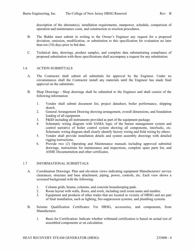
1.6 ACTION SUBMITTALS
A. The Contractor shall submit all submittals for approval by the Engineer. Under no
circumstances shall the Contractor install any materials until the Engineer has made final
approval on the submittals.
B. Shop Drawings - Shop drawings shall be submitted to the Engineer and shall consist of the
following information:
1. Vendor shall submit document list, project datasheet, boiler performance, shipping
sketch.
2. General Arrangement Drawing showing arrangement, overall dimensions, and foundation
loading of all equipment.
3. P&ID including all instruments provided as part of the equipment package.
4. Schematic wiring diagram with SAMA logic of the burner management system and
control narrative of boiler control system showing all components, interlocks, etc.
Schematic wiring diagram shall clearly identify factory wiring and field wiring by others.
5. Vendor shall provide installation details and system assembly drawings with detailed
rigging instructions.
6. Provide two (2) Operating and Maintenance manuals including approved submittal
drawings, instructions for maintenance and inspections, complete spare parts list, and
ASME Documentation and other certificates.
1.7 INFORMATIONAL SUBMITTALS
A. Coordination Drawings: Plan and elevation views indicating equipment Manufacturers' service
clearances, structure and base attachment, piping, power, controls, etc. Each view shows a
screened background with the following:
1. Column grids, beams, columns, and concrete housekeeping pads.
2. Room layout with walls, floors, and roofs, including each room name and number.
3. Equipment and products of other trades that are located in vicinity of HRSG and are part
of final installation, such as lighting, fire-suppression systems, and plumbing systems.
B. Seismic Qualification Certificates: For HRSG, accessories, and components, from
Manufacturer.
1. Basis for Certification: Indicate whether withstand certification is based on actual test of
assembled components or on calculation.
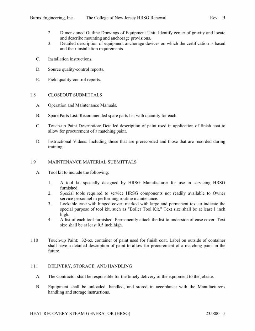
Burns Engineering, Inc. The College of New Jersey HRSG Renewal Rev: B
HEAT RECOVERY STEAM GENERATOR (HRSG) 235800 - 5
2. Dimensioned Outline Drawings of Equipment Unit: Identify center of gravity and locate
and describe mounting and anchorage provisions.
3. Detailed description of equipment anchorage devices on which the certification is based
and their installation requirements.
C. Installation instructions.
D. Source quality-control reports.
E. Field quality-control reports.
1.8 CLOSEOUT SUBMITTALS
A. Operation and Maintenance Manuals.
B. Spare Parts List: Recommended spare parts list with quantity for each.
C. Touch-up Paint Description: Detailed description of paint used in application of finish coat to
allow for procurement of a matching paint.
D. Instructional Videos: Including those that are prerecorded and those that are recorded during
training.
1.9 MAINTENANCE MATERIAL SUBMITTALS
A. Tool kit to include the following:
1. A tool kit specially designed by HRSG Manufacturer for use in servicing HRSG
furnished.
2. Special tools required to service HRSG components not readily available to Owner
service personnel in performing routine maintenance.
3. Lockable case with hinged cover, marked with large and permanent text to indicate the
special purpose of tool kit, such as "Boiler Tool Kit." Text size shall be at least 1 inch
high.
4. A list of each tool furnished. Permanently attach the list to underside of case cover. Text
size shall be at least 0.5 inch high.
1.10 Touch-up Paint: 32-oz. container of paint used for finish coat. Label on outside of container
shall have a detailed description of paint to allow for procurement of a matching paint in the
future.
1.11 DELIVERY, STORAGE, AND HANDLING
A. The Contractor shall be responsible for the timely delivery of the equipment to the jobsite.
B. Equipment shall be unloaded, handled, and stored in accordance with the Manufacturer's
handling and storage instructions.
Burns Engineering, Inc. The College of New Jersey HRSG Renewal Rev: B
HEAT RECOVERY STEAM GENERATOR (HRSG) 235800 - 6
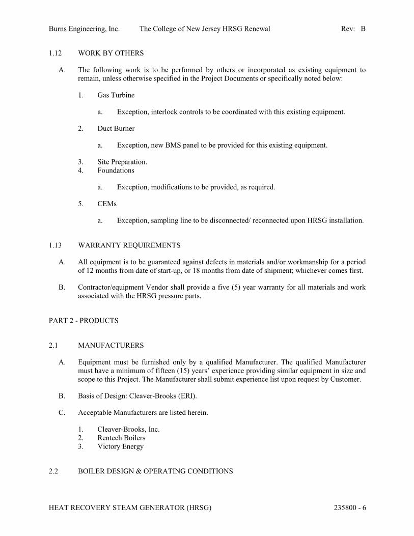
1.12 WORK BY OTHERS
A. The following work is to be performed by others or incorporated as existing equipment to
remain, unless otherwise specified in the Project Documents or specifically noted below:
1. Gas Turbine
a. Exception, interlock controls to be coordinated with this existing equipment.
2. Duct Burner
a. Exception, new BMS panel to be provided for this existing equipment.
3. Site Preparation.
4. Foundations
a. Exception, modifications to be provided, as required.
5. CEMs
a. Exception, sampling line to be disconnected/ reconnected upon HRSG installation.
1.13 WARRANTY REQUIREMENTS
A. All equipment is to be guaranteed against defects in materials and/or workmanship for a period
of 12 months from date of start-up, or 18 months from date of shipment; whichever comes first.
B. Contractor/equipment Vendor shall provide a five (5) year warranty for all materials and work
associated with the HRSG pressure parts.
PART 2 - PRODUCTS
2.1 MANUFACTURERS
A. Equipment must be furnished only by a qualified Manufacturer. The qualified Manufacturer
must have a minimum of fifteen (15) years’ experience providing similar equipment in size and
scope to this Project. The Manufacturer shall submit experience list upon request by Customer.
B. Basis of Design: Cleaver-Brooks (ERI).
C. Acceptable Manufacturers are listed herein.
1. Cleaver-Brooks, Inc.
2. Rentech Boilers
3. Victory Energy
2.2 BOILER DESIGN & OPERATING CONDITIONS
Burns Engineering, Inc. The College of New Jersey HRSG Renewal Rev: B
HEAT RECOVERY STEAM GENERATOR (HRSG) 235800 - 7
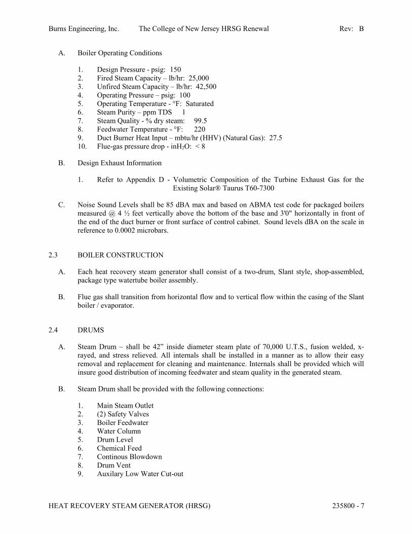
A. Boiler Operating Conditions
1. Design Pressure - psig: 150
2. Fired Steam Capacity – lb/hr: 25,000
3. Unfired Steam Capacity – lb/hr: 42,500
4. Operating Pressure – psig: 100
5. Operating Temperature - °F: Saturated
6. Steam Purity – ppm TDS 1
7. Steam Quality - % dry steam: 99.5
8. Feedwater Temperature - °F: 220
9. Duct Burner Heat Input – mbtu/hr (HHV) (Natural Gas): 27.5
10. Flue-gas pressure drop - inH2O: < 8
B. Design Exhaust Information
1. Refer to Appendix D - Volumetric Composition of the Turbine Exhaust Gas for the
Existing Solar® Taurus T60-7300
C. Noise Sound Levels shall be 85 dBA max and based on ABMA test code for packaged boilers
measured @ 4 ½ feet vertically above the bottom of the base and 3'0" horizontally in front of
the end of the duct burner or front surface of control cabinet. Sound levels dBA on the scale in
reference to 0.0002 microbars.
2.3 BOILER CONSTRUCTION
A. Each heat recovery steam generator shall consist of a two-drum, Slant style, shop-assembled,
package type watertube boiler assembly.
B. Flue gas shall transition from horizontal flow and to vertical flow within the casing of the Slant
boiler / evaporator.
2.4 DRUMS
A. Steam Drum – shall be 42” inside diameter steam plate of 70,000 U.T.S., fusion welded, x-
rayed, and stress relieved. All internals shall be installed in a manner as to allow their easy
removal and replacement for cleaning and maintenance. Internals shall be provided which will
insure good distribution of incoming feedwater and steam quality in the generated steam.
B. Steam Drum shall be provided with the following connections:
1. Main Steam Outlet
2. (2) Safety Valves
3. Boiler Feedwater
4. Water Column
5. Drum Level
6. Chemical Feed
7. Continous Blowdown
8. Drum Vent
9. Auxilary Low Water Cut-out
Burns Engineering, Inc. The College of New Jersey HRSG Renewal Rev: B
HEAT RECOVERY STEAM GENERATOR (HRSG) 235800 - 8
C. Water (Mud) Drum – shall be 30” OD of either fusion welded plate or seamless steel pipe. The
water drum shall have suitable internal baffle or angle to insure proper blowdown of boiler.
D. Water Drum shall be provided with the following Connections
1. Intermittent Blowdown
E. Each steam and water drum shall be provided with two (2) hinged manhole openings (12” x 16”
minimum) to assure visibility and ventilation during inspection and maintenance. Each manhole
opening shall be complete with manhole plate, yoke, nuts, bolts, washers, and gaskets.
F. No part of the boiler drums shall be directly exposed to furnace radiation. Refractory shall be
utilized to protect from radiant heat.
G. Drums shall include a corrosion allowance of 0.125”.
H. All connections larger than 1.5" shall be flanged.
I. Connections less than or equal to 1.5” shall be flanged or welded.
J. Tube to drum connections shall be rolled and seal welded. Compression fittings or alternate
tube to drum configurations shall not be accepted. (optional)
2.5 BOILER CONVECTION SECTION
A. All tubes shall be 2" O.D., electric resistance welded, carbon steel SA-178-A with helically
wound and simultaneously welded carbon steel fins, where applicable and shall be designed and
arranged to provide for natural circulation in the proper direction at all loads. Tubes of variable
diameter, such as swaged tubes, shall not be permitted.
B. Tubes shall be oriented on an inclined plain to maximize the heating surface within a given
footprint.
C. Tubes immediately downstream of the duct burner shall be bare and shall not include extended
finning.
D. No tube shall enter the lower drum below the horizontal drum centerline. Tubes shall not have
any reverse bends or "pockets" which would prevent complete drainage of the boiler through
the lower blowoff opening.
E. Each tube hole shall be serrated to assure the tightest possible mechanical joint.
F. All tubes shall be a minimum of 0.105” wall thickness.
G. Tube rows immediately downstream of the duct burner shall be bare tube.
2.6 DOWNCOMERS
A. Downcomers shall be of sufficient quantity and size for adequate circulation under all operating
scenarios.
Burns Engineering, Inc. The College of New Jersey HRSG Renewal Rev: B
HEAT RECOVERY STEAM GENERATOR (HRSG) 235800 - 9
B. Downcomers shall be completely external to the gas path.
C. All downcomers shall include vortex breakers.
D. No downcomers shall enter the steam drum above the normal water level.
2.7 CASING, SETTING, AND INSULATION
A. The external casing shall be 12-gauge steel and shall completely enclose the unit with the
exception of the four drum heads. The drum heads shall be insulated in the field by others. The
steam drum shall be insulated and cased with 12-gauge steel.
B. The average surface temperature of the casing shall not exceed 50°F over ambient temperature
with a surface wind velocity of two feet per second while the boiler is operating at full capacity.
C. Casing shall include internal insulation of sufficient thickness obtain the required average
casing temperature.
D. Refractory shall not be utilized within the heat recovery steam generator.
E. All insulation shall include a protective liner of adequate material to withstand the design
temperature including luminous radiation from combustion sources.
F. Insulation over the top of the steam drum is to be a minimum of 3 inches thick 1000°F
insulating blanket of the fiber glass or mineral wool type.
G. A welded heavy beam and channel boiler base shall support the steam generating equipment
and uniformly distribute the loading over the foundation area.
H. The exterior steel surfaces of each unit shall be completely cleaned by solvent cleaning,
scraping, or grinding and have one (1) coat each of high heat resistant primer and finish coat.
2.8 TRIM AND INSTRUMENTATION
A. Each unit shall be furnished with the following boiler trim and instrumentation which shall be in
accordance with ASME Code requirements and conforming to the best standards and practice.
B. All flow transmitters shall include at a minimum a three-valve manifold.
C. All pressure transmitters and gauges for steam and water service shall include at a minimum a
two valve manifold.
D. Boiler Trim and Instrumentation
1. This equipment shall be factory-mounted, complete with integral connecting piping,
valves, and fittings. All valves and control apparatus are to be designed for the specific
application for which they are utilized in full compliance with the regulatory codes
specified above. Drain lines, as applicable, shall terminate with a valve 5 feet above
operating floor level. If clearances do not permit shipment of all apparatus mounted on
the unit, the subassemblies affected can be shipped loose for field mounting by others.
Burns Engineering, Inc. The College of New Jersey HRSG Renewal Rev: B
HEAT RECOVERY STEAM GENERATOR (HRSG) 235800 - 10
a. Two (2) Drum Safety Valves
b. Two (2) Drum Safety Valve Drip-pan Elbows
c. One (1) Drum Vent Valve
d. One (1) drum pressure transmitter and pressure gauge.
e. One (1) high pressure switch and one (1) high-high pressure switch
f. One (1) Drum Level Transmitter
g. One (1) auxiliary low water cut-out
h. One (1) Water Column complete with one (1) gauge glass and one (1) low level
probe
i. One (1) remote level indication for control room with local indication
j. Continuous Blowdown: One (1) angled stop valve, conductivity probe, automated
metering valve with bypass
k. Chemical Feed: One (1) angled stop valve and one (1) check valve
l. Intermittent Blowdown: One (1) stop and one (1) throttling valve
l.2. This equipment shall be provided in accordance with ASME Boiler Pressure Vessel Code
(BPVC) Section I paragraph PG-60.1.
E. STEAM TRIM AND INSTRUMENTATION
1. Trim shall be made into subassemblies including necessary piping, fittings, etc. for field
mounting by others.
a. Non-return Valve
b. Spool piece with vent and drain valves
c. Main steam stop Valve
d. Steam Pressure Transmitter
e. Steam temperature transmitter
F. FEEDWATER TRIM AND INSTRUMENTATION
1. Trim shall be made into subassemblies including necessary piping, fittings, etc. for field
mounting by others.
a. Feedwater Flow Element and transmitter
b. One (1) feedwater control valve station including one (1) feedwater control valve,
two (2) isolation valves, one (1) bypass valve, and drain valves
c. One (1) feedwater stop valve and one (1) feedwater check valve
d. One (1) feedwater temperature transmitter
e. One (1) post economizer feedwater temperature transmitter
G. ECONOMIZER TRIM AND INSTRUMENTATION
1. Trim shall be made into subassemblies including necessary piping, fittings, etc. for field
mounting by others.
a. One (1) vent valve and one (1) drain valve
b. One (1) inlet and one (1) outlet temperature gauge
c. One (1) inlet isolation, one (1) bypass, one (1) outlet isolation valve, and one (1)
safety relief valve
Burns Engineering, Inc. The College of New Jersey HRSG Renewal Rev: B
HEAT RECOVERY STEAM GENERATOR (HRSG) 235800 - 11
H. FLUE GAS TRIM
1. One (1) inlet pressure transmitter
2. One (1) inlet temperature transmitter
3. One observation port per duct burner element with a minimum of two and one
observation port at the furnace exit viewing the heat transfer tubes at the exit of the
furnace
4. Two (2) furnace temperature transmitters
5. One (1) economizer inlet and one (1) economizer outlet temperature transmitter
2.9 ECONOMIZER
A. Refer to Exhaust Stack Economizer Specification #235830.
2.10 HRSG CONTROL SYSTEM
A. A control panel will be provided and mounted within a freestanding panel.
B. The combustion and feedwater controls shall consistsconsist of one (1) Allen-Bradley
Compactlogix PLC based controllerPLC mounted and wired in the boiler control panel.
B.C. The Burner Management System (BMS) controls for the existing duct burner shall be replaced
as part of this project. The BMS shall consist of one (1) Allen-Bradley Compactlogix PLC fed
from an independent power source (from that of the CCS PLC).
C.D. Duct burner firing rate control shall be controlled via the drum pressure transmitter.
D.E. Turbine Interlock Controls shall be provided to prevent operation of the HRSG and/or duct
burner without the Combustion Turbine Generator (CTG) in steady operation.
E.F. Feedwater Controls.
1. A three elementthree-element feedwater control system shall control the drum level.
F.G. BURNER MANAGEMENT SYSTEM
1. Vendor to provide a complete package pre-wired and tested burner management system
for single fuel (natural gas).
2. The BMS shall be comprised of hardwired relay contacts, a Programmable Logic
Controller (PLC) and a flame detection system. The hardwired relay contacts shall
provide safety interlocks, control trip functions and serve as input/output interface
between the PLC and selected field devices. The PLC shall be manufactured by Allen-
Bradley, or Approved Equal, with Ethernet communications capabilities to HRSG and
Owner’s Balance of Plant (BOP) Control System. A minimum of 20% spare analog and
discrete I/O shall be provided. The BMS shall include a Human Machine Interface
(HMI). The HMI shall be manufactured by Allen-Bradley, or Approved Equal.
3. The BMS control panel shall include a flame scanning system to properly shutdown the
burner system in the event of pilot or main flame failure during duct burner operation.
The flame scanners shall be mounted with an adjustable base joint to allow optimal flame
sighting and shall be pre-wired to local panel mounted on the duct burner assembly. The
Burns Engineering, Inc. The College of New Jersey HRSG Renewal Rev: B
HEAT RECOVERY STEAM GENERATOR (HRSG) 235800 - 12
flame scanners shall be air purged and properly cooled to protect them from excessive
heat and debris.
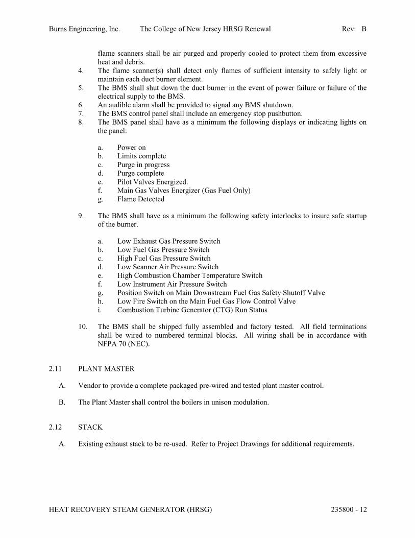
4. The flame scanner(s) shall detect only flames of sufficient intensity to safely light or
maintain each duct burner element.
5. The BMS shall shut down the duct burner in the event of power failure or failure of the
electrical supply to the BMS.
6. An audible alarm shall be provided to signal any BMS shutdown.
7. The BMS control panel shall include an emergency stop pushbutton.
8. The BMS panel shall have as a minimum the following displays or indicating lights on
the panel:
a. Power on
b. Limits complete
c. Purge in progress
d. Purge complete
e. Pilot Valves Energized.
f. Main Gas Valves Energizer (Gas Fuel Only)
g. Flame Detected
9. The BMS shall have as a minimum the following safety interlocks to insure safe startup
of the burner.
a. Low Exhaust Gas Pressure Switch
b. Low Fuel Gas Pressure Switch
c. High Fuel Gas Pressure Switch
d. Low Scanner Air Pressure Switch
e. High Combustion Chamber Temperature Switch
f. Low Instrument Air Pressure Switch
g. Position Switch on Main Downstream Fuel Gas Safety Shutoff Valve
h. Low Fire Switch on the Main Fuel Gas Flow Control Valve
i. Combustion Turbine Generator (CTG) Run Status
10. The BMS shall be shipped fully assembled and factory tested. All field terminations
shall be wired to numbered terminal blocks. All wiring shall be in accordance with
NFPA 70 (NEC).
2.11 PLANT MASTER
A. Vendor to provide a complete packaged pre-wired and tested plant master control.
B. The Plant Master shall control the boilers in unison modulation.
2.12 STACK
A. Existing exhaust stack to be re-used. Refer to Project Drawings for additional requirements.
Burns Engineering, Inc. The College of New Jersey HRSG Renewal Rev: B
HEAT RECOVERY STEAM GENERATOR (HRSG) 235800 - 13
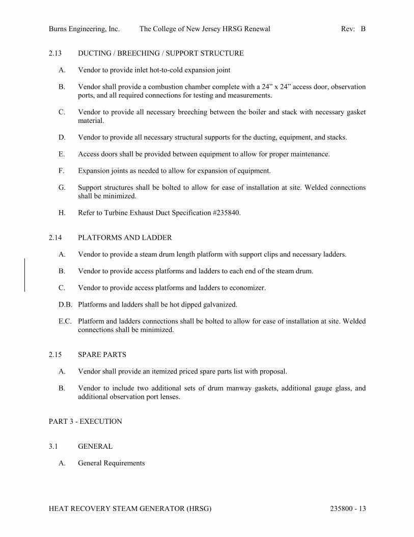
2.13 DUCTING / BREECHING / SUPPORT STRUCTURE
A. Vendor to provide inlet hot-to-cold expansion joint
B. Vendor shall provide a combustion chamber complete with a 24” x 24” access door, observation
ports, and all required connections for testing and measurements.
C. Vendor to provide all necessary breeching between the boiler and stack with necessary gasket
material.
D. Vendor to provide all necessary structural supports for the ducting, equipment, and stacks.
E. Access doors shall be provided between equipment to allow for proper maintenance.
F. Expansion joints as needed to allow for expansion of equipment.
G. Support structures shall be bolted to allow for ease of installation at site. Welded connections
shall be minimized.
H. Refer to Turbine Exhaust Duct Specification #235840.
2.14 PLATFORMS AND LADDER
A. Vendor to provide a steam drum length platform with support clips and necessary ladders.
B. Vendor to provide access platforms and ladders to each end of the steam drum.
C. Vendor to provide access platforms and ladders to economizer.
D.B. Platforms and ladders shall be hot dipped galvanized.
E.C. Platform and ladders connections shall be bolted to allow for ease of installation at site. Welded
connections shall be minimized.
2.15 SPARE PARTS
A. Vendor shall provide an itemized priced spare parts list with proposal.
B. Vendor to include two additional sets of drum manway gaskets, additional gauge glass, and
additional observation port lenses.
PART 3 - EXECUTION
3.1 GENERAL
A. General Requirements
Burns Engineering, Inc. The College of New Jersey HRSG Renewal Rev: B
HEAT RECOVERY STEAM GENERATOR (HRSG) 235800 - 14
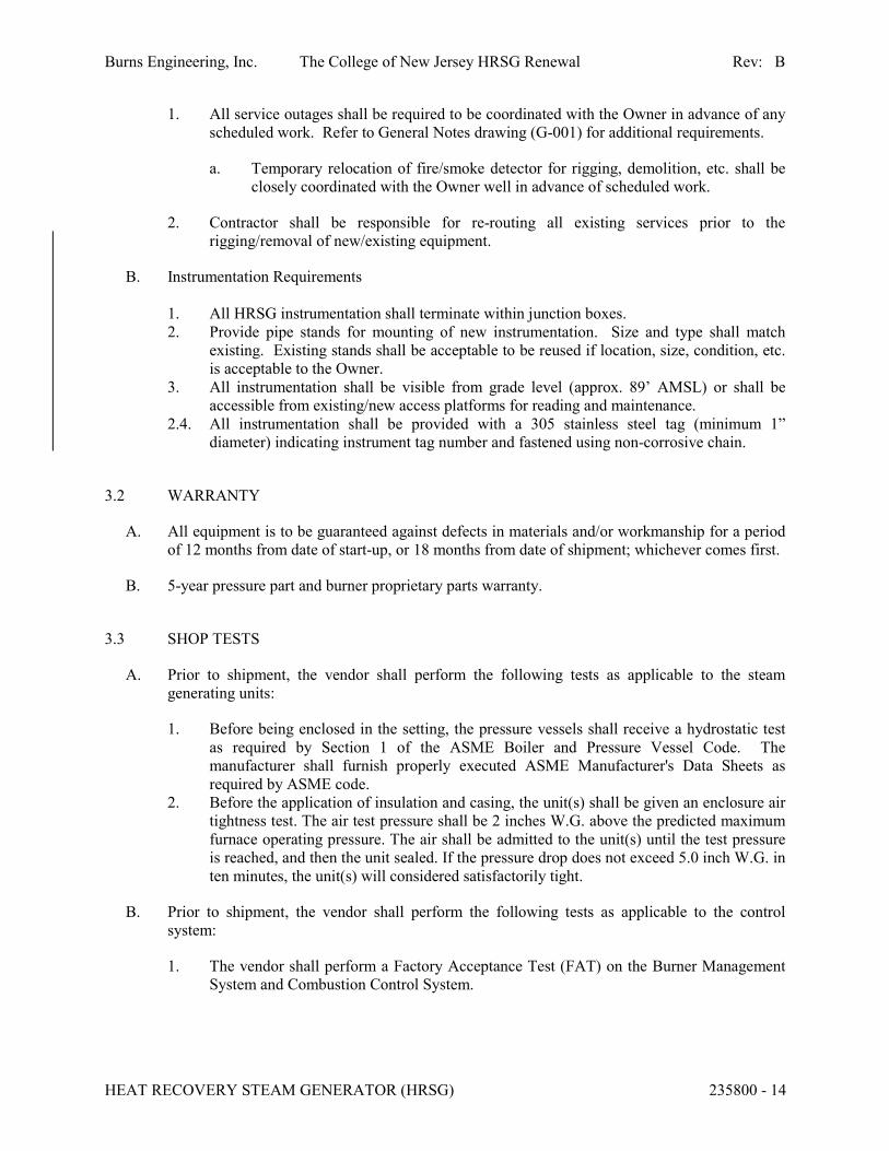
1. All service outages shall be required to be coordinated with the Owner in advance of any
scheduled work. Refer to General Notes drawing (G-001) for additional requirements.
a. Temporary relocation of fire/smoke detector for rigging, demolition, etc. shall be
closely coordinated with the Owner well in advance of scheduled work.
2. Contractor shall be responsible for re-routing all existing services prior to the
rigging/removal of new/existing equipment.
B. Instrumentation Requirements
1. All HRSG instrumentation shall terminate within junction boxes.
2. Provide pipe stands for mounting of new instrumentation. Size and type shall match
existing. Existing stands shall be acceptable to be reused if location, size, condition, etc.
is acceptable to the Owner.
3. All instrumentation shall be visible from grade level (approx. 89’ AMSL) or shall be
accessible from existing/new access platforms for reading and maintenance.
2.4. All instrumentation shall be provided with a 305 stainless steel tag (minimum 1”
diameter) indicating instrument tag number and fastened using non-corrosive chain.
3.2 WARRANTY
A. All equipment is to be guaranteed against defects in materials and/or workmanship for a period
of 12 months from date of start-up, or 18 months from date of shipment; whichever comes first.
B. 5-year pressure part and burner proprietary parts warranty.
3.3 SHOP TESTS
A. Prior to shipment, the vendor shall perform the following tests as applicable to the steam
generating units:
1. Before being enclosed in the setting, the pressure vessels shall receive a hydrostatic test
as required by Section 1 of the ASME Boiler and Pressure Vessel Code. The
manufacturer shall furnish properly executed ASME Manufacturer's Data Sheets as
required by ASME code.
2. Before the application of insulation and casing, the unit(s) shall be given an enclosure air
tightness test. The air test pressure shall be 2 inches W.G. above the predicted maximum
furnace operating pressure. The air shall be admitted to the unit(s) until the test pressure
is reached, and then the unit sealed. If the pressure drop does not exceed 5.0 inch W.G. in
ten minutes, the unit(s) will considered satisfactorily tight.
B. Prior to shipment, the vendor shall perform the following tests as applicable to the control
system:
1. The vendor shall perform a Factory Acceptance Test (FAT) on the Burner Management
System and Combustion Control System.
Burns Engineering, Inc. The College of New Jersey HRSG Renewal Rev: B
HEAT RECOVERY STEAM GENERATOR (HRSG) 235800 - 15
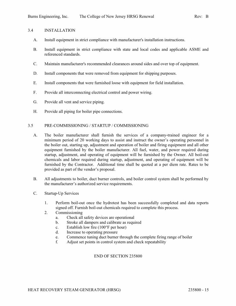
3.4 INSTALLATION
A. Install equipment in strict compliance with manufacturer's installation instructions.
B. Install equipment in strict compliance with state and local codes and applicable ASME and
referenced standards.
C. Maintain manufacturer's recommended clearances around sides and over top of equipment.
D. Install components that were removed from equipment for shipping purposes.
E. Install components that were furnished loose with equipment for field installation.
F. Provide all interconnecting electrical control and power wiring.
G. Provide all vent and service piping.
H. Provide all piping for boiler pipe connections.
3.5 PRE-COMMISSIONING / STARTUP / COMMISSIONING
A. The boiler manufacturer shall furnish the services of a company-trained engineer for a
minimum period of 20 working days to assist and instruct the owner’s operating personnel in
the boiler out, starting up, adjustment and operation of boiler and firing equipment and all other
equipment furnished by the boiler manufacturer. All fuel, water, and power required during
startup, adjustment, and operating of equipment will be furnished by the Owner. All boil-out
chemicals and labor required during startup, adjustment, and operating of equipment will be
furnished by the Contractor. Additional time shall be quoted at a per diem rate. Rates to be
provided as part of the vendor’s proposal.
B. All adjustments to boiler, duct burner controls, and boiler control system shall be performed by
the manufacturer’s authorized service requirements.
C. Startup-Up Services
1. Perform boil-out once the hydrotest has been successfully completed and data reports
signed off. Furnish boil-out chemicals required to complete this process.
2. Commissioning
a. Check all safety devices are operational
b. Stroke all dampers and calibrate as required
c. Establish low fire (100°F per hour)
d. Increase to operating pressure
e. Commence tuning duct burner through the complete firing range of boiler
f. Adjust set points in control system and check repeatability
END OF SECTION 235800

Burns Engineering, Inc. The College of New Jersey HRSG Renewal Rev: B
HEAT RECOVERY STEAM GENERATOR (HRSG) 235800 - 16
APPENDIX A
HRSG Performance For Gas Turbine Data
Burns Engineering, Inc. The College of New Jersey HRSG Renewal Rev: B
HEAT RECOVERY STEAM GENERATOR (HRSG) 235800 - 17
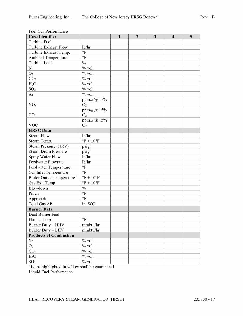
Fuel Gas Performance
Case Identifier 1 2 3 4 5
Turbine Fuel
Turbine Exhaust Flow lb/hr
Turbine Exhaust Temp. °F
Ambient Temperature °F
Turbine Load %
N2 % vol.
O2 % vol.
CO2 % vol.
H2O % vol.
SO2 % vol.
Ar % vol.
NOx
ppmvd @ 15%
O2
CO
ppmvd @ 15%
O2
VOC
ppmvd @ 15%
O2
HRSG Data
Steam Flow lb/hr
Steam Temp. °F ± 10°F
Steam Pressure (NRV) psig
Steam Drum Pressure psig
Spray Water Flow lb/hr
Feedwater Flowrate lb/hr
Feedwater Temperature °F
Gas Inlet Temperature °F
Boiler Outlet Temperature °F ± 10°F
Gas Exit Temp °F ± 10°F
Blowdown %
Pinch °F
Approach °F
Total Gas ΔP in. WC
Burner Data
Duct Burner Fuel
Flame Temp °F
Burner Duty – HHV mmbtu/hr
Burner Duty – LHV mmbtu/hr
Products of Combustion
N2 % vol.
O2 % vol.
CO2 % vol.
H2O % vol.
SO2 % vol.
*Items highlighted in yellow shall be guaranteed.
Liquid Fuel Performance
Burns Engineering, Inc. The College of New Jersey HRSG Renewal Rev: B
HEAT RECOVERY STEAM GENERATOR (HRSG) 235800 - 18
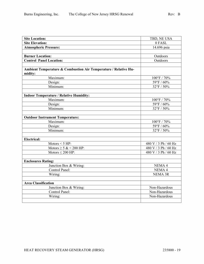
APPENDIX B
Site and Utility Data for Site Conditions
Burns Engineering, Inc. The College of New Jersey HRSG Renewal Rev: B
HEAT RECOVERY STEAM GENERATOR (HRSG) 235800 - 19
Site Location: TBD, NE USA
Site Elevation: 0 FASL
Atmospheric Pressure: 14.696 psia
Burner Location: Outdoors
Control Panel Location: Outdoors
Ambient Temperature & Combustion Air Temperature / Relative Hu-
midity:
Maximum: 100°F / 70%
Design: 59°F / 60%
Minimum: 32°F / 50%
Indoor Temperature / Relative Humidity:
Maximum: 100°F / 70%
Design: 59°F / 60%
Minimum: 32°F / 50%
Outdoor Instrument Temperature:
Maximum: 100°F / 70%
Design: 59°F / 60%
Minimum: 32°F / 50%
Electrical:
Motors < 5 HP: 480 V / 3 Ph / 60 Hz
Motors ≥ 5 & < 200 HP: 480 V / 3 Ph / 60 Hz
Motors ≤ 200 HP: 480 V / 3 Ph / 60 Hz
Enclosures Rating:
Junction Box & Wiring: NEMA 4
Control Panel: NEMA 4
Wiring: NEMA 3R
Area Classification
Junction Box & Wiring: Non-Hazardous
Control Panel: Non-Hazardous
Wiring: Non-Hazardous

Burns Engineering, Inc. The College of New Jersey HRSG Renewal Rev: B
HEAT RECOVERY STEAM GENERATOR (HRSG) 235800 - 20
APPENDIX C
Plot Plan and Space Requirements for Overall Plot Space and Available Footprint For Equipment
Specified Herein
Burns Engineering, Inc. The College of New Jersey HRSG Renewal Rev: B
HEAT RECOVERY STEAM GENERATOR (HRSG) 235800 - 21
APPENDIX D
Volumetric Composition of the Turbine Exhaust Gas for the Existing Solar Turbines T60-7300

SOLAR TURBINES INCORPORATED DATE RUN: 2-Feb-18ENGINE PERFORMANCE CODE REV. 4.18.1.20.12 RUN BY: Brian C SpencerCUSTOMER: TCNJJOB ID: PD 46841 CG93686
--- SUMMARY OF ENGINE EXHAUST ANALYSIS --- POINT NUMBER 1
kW= 5935, %Full Load=100.0, Elev= 140ft, %RH= 60.0, Temperature= 0.0F
GENERAL INPUT SPECIFICATIONS
ENGINE FUEL: SD NATURAL GAS 29.78 in Hg AMBIENT PRESSURE 60.0 percent RELATIVE HUMIDITY 0.0006 --- SP. HUMIDITY (LBM H2O/LBM DRY AIR)
FUEL GAS COMPOSITION (VOLUME PERCENT)LHV (Btu/Scf) = 939.2 SG = 0.5970 W.I. @60F (Btu/Scf) = 1215.6
Methane (CH4) = 92.7899 Ethane (C2H6) = 4.1600 Propane (C3H8) = 0.8400 N-Butane (C4H10) = 0.1800 N-Pentane (C5H12) = 0.0400 Hexane (C6H14) = 0.0400 Carbon Dioxide (CO2) = 0.4400 Hydrogen Sulfide (H2S) = 0.0001 Nitrogen (N2) = 1.5100
STANDARD CONDITIONS FOR GAS VOLUMES: Temperature: 60 deg F Pressure: 29.92 in HgNORMAL CONDITIONS FOR GAS VOLUMES: Temperature: 32 deg F Pressure: 29.92 in Hg
!!! PLEASE, SUBMIT INQUIRY ON GAS FUEL SUITABILITY TO SAN DIEGO !!!
GENERAL OUTPUT DATA
3228. lbm/hr FUEL FLOW 1180.75 Scfm FUEL FLOW 20612. Btu/lbm LOWER HEATING VALUE 939. Btu/Scf LOWER HEATING VALUE 41368. Scfm EXHAUST FLOW @ 14.7 PSIA & 60F 107789. Acfm ACTUAL EXHAUST FLOW CFm 186984. lbm/hr EXHAUST GAS FLOW 28.59 --- MOLECULAR WEIGHT OF EXHAUST GAS 57.02 --- AIR/FUEL RATIO
EXHAUST GAS ANALYSIS
ARGON CO2 H2O N2 O2
0.91 3.03 5.87 75.76 14.44 VOLUME PERCENT WET 0.96 3.22 0.00 80.48 15.34 VOLUME PERCENT DRY 2366. 8714. 6912. 138777. 30211. lbm/hr 0.73 2.70 2.14 42.99 9.36 g/(g FUEL)
ESTIMATES ONLY, NOT GUARANTEED

SOLAR TURBINES INCORPORATED DATE RUN: 2-Feb-18ENGINE PERFORMANCE CODE REV. 4.18.1.20.12 RUN BY: Brian C SpencerCUSTOMER: TCNJJOB ID: PD 46841 CG93686
NEW EQUIPMENT PREDICTED EMISSION PERFORMANCE DATA FOR POINT NUMBER 1
Fuel: SD NATURAL GAS Customer: TCNJ Water Injection: NO Inquiry Number: Model: TAURUS 60-7300S GSC STANDARD DUAL Emissions Data: REV. 0.0
The following predicted emissions performance is based on the following specificsingle point:
kW= 5935, %Full Load=100.0, Elev= 140ft, %RH= 60.0, Temperature= 0.0F
NOX CO UHC 25.00 50.00 25.00 PPMvd at 15% O2 29.24 35.60 10.19 ton/yr 0.100 0.122 0.035 lbm/MMBtu (Fuel LHV) 1.08 1.31 0.38 lbm/(MW-hr) (gas turbine shaft pwr) 6.67 8.13 2.33 lbm/hr
NOTES: 1. For short-term emission limits such as lbs/hr., Solar recommends using "worst case" anticipated operating conditions specific to the application and the site conditions. Worst case for one pollutant is not necessarily the same for another. 2. Solar's typical SoLoNOx warranty, for ppm values, is available for greater than 0 deg F or -20 deg C, and between 50% and 100% load or gas, fuel, and between 65% and 100% load for liquid fuel except for the Centaur 40). An emission warranty for non-SoLoN x equipment is available for greater than 0 deg F or -20 deg C an 3. Fuel must meet Solar standard fuel specification ES 9-98. Emissions are based on the attached fuel composition, or, San Diego natural gas or equivalent. 4. If needed, Solar can provide Product Information Letters to address turbine operation outside typical warranty ranges, as well as non- warranted emissions of SO2, PM10/2.5, VOC, and formaldehyde. 5. Solar can provide factory testing in San Diego to ensure the actual unit(s) meet the above values within the tolerances quoted. Pricing and schedule impact will be provided upon request. 6. Any emissions warranty is applicable only for steady-state conditions and does not apply during start-up, shut-down, malfunction, or transient event.
ESTIMATES ONLY, NOT GUARANTEED

SOLAR TURBINES INCORPORATED DATE RUN: 2-Feb-18ENGINE PERFORMANCE CODE REV. 4.18.1.20.12 RUN BY: Brian C SpencerCUSTOMER: TCNJJOB ID: PD 46841 CG93686
--- SUMMARY OF ENGINE EXHAUST ANALYSIS --- POINT NUMBER 2
kW= 5584, %Full Load=100.0, Elev= 140ft, %RH= 60.0, Temperature= 20.0F
GENERAL INPUT SPECIFICATIONS
ENGINE FUEL: SD NATURAL GAS 29.78 in Hg AMBIENT PRESSURE 60.0 percent RELATIVE HUMIDITY 0.0014 --- SP. HUMIDITY (LBM H2O/LBM DRY AIR)
FUEL GAS COMPOSITION (VOLUME PERCENT)LHV (Btu/Scf) = 939.2 SG = 0.5970 W.I. @60F (Btu/Scf) = 1215.6
Methane (CH4) = 92.7899 Ethane (C2H6) = 4.1600 Propane (C3H8) = 0.8400 N-Butane (C4H10) = 0.1800 N-Pentane (C5H12) = 0.0400 Hexane (C6H14) = 0.0400 Carbon Dioxide (CO2) = 0.4400 Hydrogen Sulfide (H2S) = 0.0001 Nitrogen (N2) = 1.5100
STANDARD CONDITIONS FOR GAS VOLUMES: Temperature: 60 deg F Pressure: 29.92 in HgNORMAL CONDITIONS FOR GAS VOLUMES: Temperature: 32 deg F Pressure: 29.92 in Hg
!!! PLEASE, SUBMIT INQUIRY ON GAS FUEL SUITABILITY TO SAN DIEGO !!!
GENERAL OUTPUT DATA
3083. lbm/hr FUEL FLOW 1127.85 Scfm FUEL FLOW 20612. Btu/lbm LOWER HEATING VALUE 939. Btu/Scf LOWER HEATING VALUE 40660. Scfm EXHAUST FLOW @ 14.7 PSIA & 60F 107559. Acfm ACTUAL EXHAUST FLOW CFm 183764. lbm/hr EXHAUST GAS FLOW 28.59 --- MOLECULAR WEIGHT OF EXHAUST GAS 58.69 --- AIR/FUEL RATIO
EXHAUST GAS ANALYSIS
ARGON CO2 H2O N2 O2
0.91 2.94 5.83 75.72 14.60 VOLUME PERCENT WET 0.96 3.12 0.00 80.41 15.50 VOLUME PERCENT DRY 2324. 8320. 6749. 136341. 30026. lbm/hr 0.75 2.70 2.19 44.22 9.74 g/(g FUEL)
ESTIMATES ONLY, NOT GUARANTEED

SOLAR TURBINES INCORPORATED DATE RUN: 2-Feb-18ENGINE PERFORMANCE CODE REV. 4.18.1.20.12 RUN BY: Brian C SpencerCUSTOMER: TCNJJOB ID: PD 46841 CG93686
NEW EQUIPMENT PREDICTED EMISSION PERFORMANCE DATA FOR POINT NUMBER 2
Fuel: SD NATURAL GAS Customer: TCNJ Water Injection: NO Inquiry Number: Model: TAURUS 60-7300S GSC STANDARD DUAL Emissions Data: REV. 0.0
The following predicted emissions performance is based on the following specificsingle point:
kW= 5584, %Full Load=100.0, Elev= 140ft, %RH= 60.0, Temperature= 20.0F
NOX CO UHC 25.00 50.00 25.00 PPMvd at 15% O2 27.90 33.97 9.73 ton/yr 0.100 0.122 0.035 lbm/MMBtu (Fuel LHV) 1.09 1.33 0.38 lbm/(MW-hr) (gas turbine shaft pwr) 6.37 7.76 2.22 lbm/hr
NOTES: 1. For short-term emission limits such as lbs/hr., Solar recommends using "worst case" anticipated operating conditions specific to the application and the site conditions. Worst case for one pollutant is not necessarily the same for another. 2. Solar's typical SoLoNOx warranty, for ppm values, is available for greater than 0 deg F or -20 deg C, and between 50% and 100% load or gas, fuel, and between 65% and 100% load for liquid fuel except for the Centaur 40). An emission warranty for non-SoLoN x equipment is available for greater than 0 deg F or -20 deg C an 3. Fuel must meet Solar standard fuel specification ES 9-98. Emissions are based on the attached fuel composition, or, San Diego natural gas or equivalent. 4. If needed, Solar can provide Product Information Letters to address turbine operation outside typical warranty ranges, as well as non- warranted emissions of SO2, PM10/2.5, VOC, and formaldehyde. 5. Solar can provide factory testing in San Diego to ensure the actual unit(s) meet the above values within the tolerances quoted. Pricing and schedule impact will be provided upon request. 6. Any emissions warranty is applicable only for steady-state conditions and does not apply during start-up, shut-down, malfunction, or transient event.
ESTIMATES ONLY, NOT GUARANTEED
SOLAR TURBINES INCORPORATED DATE RUN: 2-Feb-18ENGINE PERFORMANCE CODE REV. 4.18.1.20.12 RUN BY: Brian C SpencerCUSTOMER: TCNJJOB ID: PD 46841 CG93686
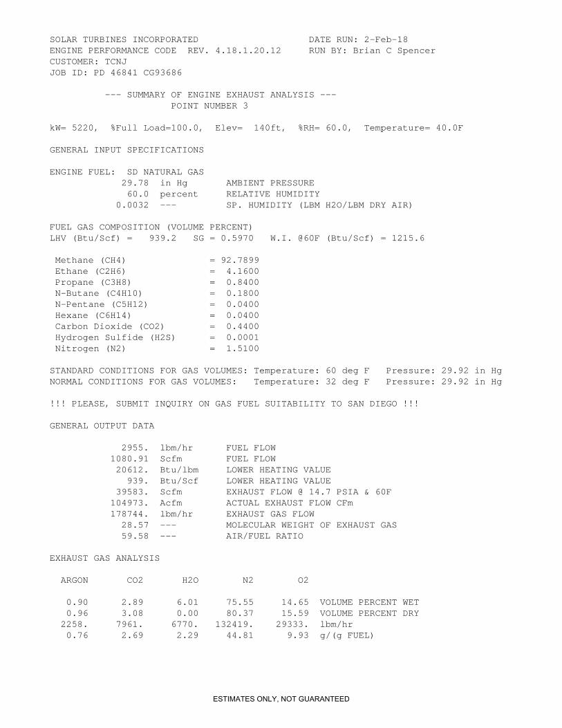
--- SUMMARY OF ENGINE EXHAUST ANALYSIS --- POINT NUMBER 3
kW= 5220, %Full Load=100.0, Elev= 140ft, %RH= 60.0, Temperature= 40.0F
GENERAL INPUT SPECIFICATIONS
ENGINE FUEL: SD NATURAL GAS 29.78 in Hg AMBIENT PRESSURE 60.0 percent RELATIVE HUMIDITY 0.0032 --- SP. HUMIDITY (LBM H2O/LBM DRY AIR)
FUEL GAS COMPOSITION (VOLUME PERCENT)LHV (Btu/Scf) = 939.2 SG = 0.5970 W.I. @60F (Btu/Scf) = 1215.6
Methane (CH4) = 92.7899 Ethane (C2H6) = 4.1600 Propane (C3H8) = 0.8400 N-Butane (C4H10) = 0.1800 N-Pentane (C5H12) = 0.0400 Hexane (C6H14) = 0.0400 Carbon Dioxide (CO2) = 0.4400 Hydrogen Sulfide (H2S) = 0.0001 Nitrogen (N2) = 1.5100
STANDARD CONDITIONS FOR GAS VOLUMES: Temperature: 60 deg F Pressure: 29.92 in HgNORMAL CONDITIONS FOR GAS VOLUMES: Temperature: 32 deg F Pressure: 29.92 in Hg
!!! PLEASE, SUBMIT INQUIRY ON GAS FUEL SUITABILITY TO SAN DIEGO !!!
GENERAL OUTPUT DATA
2955. lbm/hr FUEL FLOW 1080.91 Scfm FUEL FLOW 20612. Btu/lbm LOWER HEATING VALUE 939. Btu/Scf LOWER HEATING VALUE 39583. Scfm EXHAUST FLOW @ 14.7 PSIA & 60F 104973. Acfm ACTUAL EXHAUST FLOW CFm 178744. lbm/hr EXHAUST GAS FLOW 28.57 --- MOLECULAR WEIGHT OF EXHAUST GAS 59.58 --- AIR/FUEL RATIO
EXHAUST GAS ANALYSIS
ARGON CO2 H2O N2 O2
0.90 2.89 6.01 75.55 14.65 VOLUME PERCENT WET 0.96 3.08 0.00 80.37 15.59 VOLUME PERCENT DRY 2258. 7961. 6770. 132419. 29333. lbm/hr 0.76 2.69 2.29 44.81 9.93 g/(g FUEL)
ESTIMATES ONLY, NOT GUARANTEED

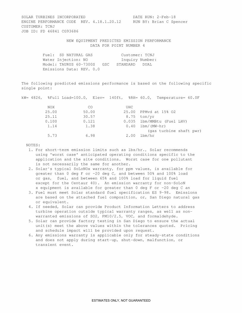
SOLAR TURBINES INCORPORATED DATE RUN: 2-Feb-18ENGINE PERFORMANCE CODE REV. 4.18.1.20.12 RUN BY: Brian C SpencerCUSTOMER: TCNJJOB ID: PD 46841 CG93686
NEW EQUIPMENT PREDICTED EMISSION PERFORMANCE DATA FOR POINT NUMBER 3
Fuel: SD NATURAL GAS Customer: TCNJ Water Injection: NO Inquiry Number: Model: TAURUS 60-7300S GSC STANDARD DUAL Emissions Data: REV. 0.0
The following predicted emissions performance is based on the following specificsingle point:
kW= 5220, %Full Load=100.0, Elev= 140ft, %RH= 60.0, Temperature= 40.0F
NOX CO UHC 25.00 50.00 25.00 PPMvd at 15% O2 26.69 32.49 9.31 ton/yr 0.100 0.122 0.035 lbm/MMBtu (Fuel LHV) 1.12 1.36 0.39 lbm/(MW-hr) (gas turbine shaft pwr) 6.09 7.42 2.12 lbm/hr
NOTES: 1. For short-term emission limits such as lbs/hr., Solar recommends using "worst case" anticipated operating conditions specific to the application and the site conditions. Worst case for one pollutant is not necessarily the same for another. 2. Solar's typical SoLoNOx warranty, for ppm values, is available for greater than 0 deg F or -20 deg C, and between 50% and 100% load or gas, fuel, and between 65% and 100% load for liquid fuel except for the Centaur 40). An emission warranty for non-SoLoN x equipment is available for greater than 0 deg F or -20 deg C an 3. Fuel must meet Solar standard fuel specification ES 9-98. Emissions are based on the attached fuel composition, or, San Diego natural gas or equivalent. 4. If needed, Solar can provide Product Information Letters to address turbine operation outside typical warranty ranges, as well as non- warranted emissions of SO2, PM10/2.5, VOC, and formaldehyde. 5. Solar can provide factory testing in San Diego to ensure the actual unit(s) meet the above values within the tolerances quoted. Pricing and schedule impact will be provided upon request. 6. Any emissions warranty is applicable only for steady-state conditions and does not apply during start-up, shut-down, malfunction, or transient event.
ESTIMATES ONLY, NOT GUARANTEED

SOLAR TURBINES INCORPORATED DATE RUN: 2-Feb-18ENGINE PERFORMANCE CODE REV. 4.18.1.20.12 RUN BY: Brian C SpencerCUSTOMER: TCNJJOB ID: PD 46841 CG93686
--- SUMMARY OF ENGINE EXHAUST ANALYSIS --- POINT NUMBER 4
kW= 4826, %Full Load=100.0, Elev= 140ft, %RH= 60.0, Temperature= 60.0F
GENERAL INPUT SPECIFICATIONS
ENGINE FUEL: SD NATURAL GAS 29.78 in Hg AMBIENT PRESSURE 60.0 percent RELATIVE HUMIDITY 0.0067 --- SP. HUMIDITY (LBM H2O/LBM DRY AIR)
FUEL GAS COMPOSITION (VOLUME PERCENT)LHV (Btu/Scf) = 939.2 SG = 0.5970 W.I. @60F (Btu/Scf) = 1215.6
Methane (CH4) = 92.7899 Ethane (C2H6) = 4.1600 Propane (C3H8) = 0.8400 N-Butane (C4H10) = 0.1800 N-Pentane (C5H12) = 0.0400 Hexane (C6H14) = 0.0400 Carbon Dioxide (CO2) = 0.4400 Hydrogen Sulfide (H2S) = 0.0001 Nitrogen (N2) = 1.5100
STANDARD CONDITIONS FOR GAS VOLUMES: Temperature: 60 deg F Pressure: 29.92 in HgNORMAL CONDITIONS FOR GAS VOLUMES: Temperature: 32 deg F Pressure: 29.92 in Hg
!!! PLEASE, SUBMIT INQUIRY ON GAS FUEL SUITABILITY TO SAN DIEGO !!!
GENERAL OUTPUT DATA
2790. lbm/hr FUEL FLOW 1020.62 Scfm FUEL FLOW 20612. Btu/lbm LOWER HEATING VALUE 939. Btu/Scf LOWER HEATING VALUE 38187. Scfm EXHAUST FLOW @ 14.7 PSIA & 60F 101571. Acfm ACTUAL EXHAUST FLOW CFm 172136. lbm/hr EXHAUST GAS FLOW 28.52 --- MOLECULAR WEIGHT OF EXHAUST GAS 60.79 --- AIR/FUEL RATIO
EXHAUST GAS ANALYSIS
ARGON CO2 H2O N2 O2
0.90 2.82 6.41 75.18 14.69 VOLUME PERCENT WET 0.96 3.01 0.00 80.33 15.70 VOLUME PERCENT DRY 2167. 7493. 6973. 127125. 28374. lbm/hr 0.78 2.69 2.50 45.56 10.17 g/(g FUEL)
ESTIMATES ONLY, NOT GUARANTEED
SOLAR TURBINES INCORPORATED DATE RUN: 2-Feb-18ENGINE PERFORMANCE CODE REV. 4.18.1.20.12 RUN BY: Brian C SpencerCUSTOMER: TCNJJOB ID: PD 46841 CG93686
NEW EQUIPMENT PREDICTED EMISSION PERFORMANCE DATA FOR POINT NUMBER 4
Fuel: SD NATURAL GAS Customer: TCNJ Water Injection: NO Inquiry Number: Model: TAURUS 60-7300S GSC STANDARD DUAL Emissions Data: REV. 0.0
The following predicted emissions performance is based on the following specificsingle point:
kW= 4826, %Full Load=100.0, Elev= 140ft, %RH= 60.0, Temperature= 60.0F
NOX CO UHC 25.00 50.00 25.00 PPMvd at 15% O2 25.11 30.57 8.75 ton/yr 0.100 0.121 0.035 lbm/MMBtu (Fuel LHV) 1.14 1.38 0.40 lbm/(MW-hr) (gas turbine shaft pwr) 5.73 6.98 2.00 lbm/hr
NOTES: 1. For short-term emission limits such as lbs/hr., Solar recommends using "worst case" anticipated operating conditions specific to the application and the site conditions. Worst case for one pollutant is not necessarily the same for another. 2. Solar's typical SoLoNOx warranty, for ppm values, is available for greater than 0 deg F or -20 deg C, and between 50% and 100% load or gas, fuel, and between 65% and 100% load for liquid fuel except for the Centaur 40). An emission warranty for non-SoLoN x equipment is available for greater than 0 deg F or -20 deg C an 3. Fuel must meet Solar standard fuel specification ES 9-98. Emissions are based on the attached fuel composition, or, San Diego natural gas or equivalent. 4. If needed, Solar can provide Product Information Letters to address turbine operation outside typical warranty ranges, as well as non- warranted emissions of SO2, PM10/2.5, VOC, and formaldehyde. 5. Solar can provide factory testing in San Diego to ensure the actual unit(s) meet the above values within the tolerances quoted. Pricing and schedule impact will be provided upon request. 6. Any emissions warranty is applicable only for steady-state conditions and does not apply during start-up, shut-down, malfunction, or transient event.
ESTIMATES ONLY, NOT GUARANTEED

SOLAR TURBINES INCORPORATED DATE RUN: 2-Feb-18ENGINE PERFORMANCE CODE REV. 4.18.1.20.12 RUN BY: Brian C SpencerCUSTOMER: TCNJJOB ID: PD 46841 CG93686
--- SUMMARY OF ENGINE EXHAUST ANALYSIS --- POINT NUMBER 5
kW= 4432, %Full Load=100.0, Elev= 140ft, %RH= 60.0, Temperature= 80.0F
GENERAL INPUT SPECIFICATIONS
ENGINE FUEL: SD NATURAL GAS 29.78 in Hg AMBIENT PRESSURE 60.0 percent RELATIVE HUMIDITY 0.0134 --- SP. HUMIDITY (LBM H2O/LBM DRY AIR)
FUEL GAS COMPOSITION (VOLUME PERCENT)LHV (Btu/Scf) = 939.2 SG = 0.5970 W.I. @60F (Btu/Scf) = 1215.6
Methane (CH4) = 92.7899 Ethane (C2H6) = 4.1600 Propane (C3H8) = 0.8400 N-Butane (C4H10) = 0.1800 N-Pentane (C5H12) = 0.0400 Hexane (C6H14) = 0.0400 Carbon Dioxide (CO2) = 0.4400 Hydrogen Sulfide (H2S) = 0.0001 Nitrogen (N2) = 1.5100
STANDARD CONDITIONS FOR GAS VOLUMES: Temperature: 60 deg F Pressure: 29.92 in HgNORMAL CONDITIONS FOR GAS VOLUMES: Temperature: 32 deg F Pressure: 29.92 in Hg
!!! PLEASE, SUBMIT INQUIRY ON GAS FUEL SUITABILITY TO SAN DIEGO !!!
GENERAL OUTPUT DATA
2633. lbm/hr FUEL FLOW 962.93 Scfm FUEL FLOW 20612. Btu/lbm LOWER HEATING VALUE 939. Btu/Scf LOWER HEATING VALUE 36508. Scfm EXHAUST FLOW @ 14.7 PSIA & 60F 97994. Acfm ACTUAL EXHAUST FLOW CFm 163966. lbm/hr EXHAUST GAS FLOW 28.41 --- MOLECULAR WEIGHT OF EXHAUST GAS 61.38 --- AIR/FUEL RATIO
EXHAUST GAS ANALYSIS
ARGON CO2 H2O N2 O2
0.89 2.77 7.32 74.43 14.60 VOLUME PERCENT WET 0.96 2.98 0.00 80.30 15.75 VOLUME PERCENT DRY 2051. 7024. 7609. 120325. 26953. lbm/hr 0.78 2.67 2.89 45.71 10.24 g/(g FUEL)
ESTIMATES ONLY, NOT GUARANTEED

SOLAR TURBINES INCORPORATED DATE RUN: 2-Feb-18ENGINE PERFORMANCE CODE REV. 4.18.1.20.12 RUN BY: Brian C SpencerCUSTOMER: TCNJJOB ID: PD 46841 CG93686
NEW EQUIPMENT PREDICTED EMISSION PERFORMANCE DATA FOR POINT NUMBER 5
Fuel: SD NATURAL GAS Customer: TCNJ Water Injection: NO Inquiry Number: Model: TAURUS 60-7300S GSC STANDARD DUAL Emissions Data: REV. 0.0
The following predicted emissions performance is based on the following specificsingle point:
kW= 4432, %Full Load=100.0, Elev= 140ft, %RH= 60.0, Temperature= 80.0F
NOX CO UHC 25.00 50.00 25.00 PPMvd at 15% O2 23.53 28.65 8.21 ton/yr 0.099 0.121 0.035 lbm/MMBtu (Fuel LHV) 1.16 1.41 0.40 lbm/(MW-hr) (gas turbine shaft pwr) 5.37 6.54 1.87 lbm/hr
NOTES: 1. For short-term emission limits such as lbs/hr., Solar recommends using "worst case" anticipated operating conditions specific to the application and the site conditions. Worst case for one pollutant is not necessarily the same for another. 2. Solar's typical SoLoNOx warranty, for ppm values, is available for greater than 0 deg F or -20 deg C, and between 50% and 100% load or gas, fuel, and between 65% and 100% load for liquid fuel except for the Centaur 40). An emission warranty for non-SoLoN x equipment is available for greater than 0 deg F or -20 deg C an 3. Fuel must meet Solar standard fuel specification ES 9-98. Emissions are based on the attached fuel composition, or, San Diego natural gas or equivalent. 4. If needed, Solar can provide Product Information Letters to address turbine operation outside typical warranty ranges, as well as non- warranted emissions of SO2, PM10/2.5, VOC, and formaldehyde. 5. Solar can provide factory testing in San Diego to ensure the actual unit(s) meet the above values within the tolerances quoted. Pricing and schedule impact will be provided upon request. 6. Any emissions warranty is applicable only for steady-state conditions and does not apply during start-up, shut-down, malfunction, or transient event.
ESTIMATES ONLY, NOT GUARANTEED

SOLAR TURBINES INCORPORATED DATE RUN: 2-Feb-18ENGINE PERFORMANCE CODE REV. 4.18.1.20.12 RUN BY: Brian C SpencerCUSTOMER: TCNJJOB ID: PD 46841 CG93686
--- SUMMARY OF ENGINE EXHAUST ANALYSIS --- POINT NUMBER 6
kW= 4004, %Full Load=100.0, Elev= 140ft, %RH= 60.0, Temperature=100.0F
GENERAL INPUT SPECIFICATIONS
ENGINE FUEL: SD NATURAL GAS 29.78 in Hg AMBIENT PRESSURE 60.0 percent RELATIVE HUMIDITY 0.0255 --- SP. HUMIDITY (LBM H2O/LBM DRY AIR)
FUEL GAS COMPOSITION (VOLUME PERCENT)LHV (Btu/Scf) = 939.2 SG = 0.5970 W.I. @60F (Btu/Scf) = 1215.6
Methane (CH4) = 92.7899 Ethane (C2H6) = 4.1600 Propane (C3H8) = 0.8400 N-Butane (C4H10) = 0.1800 N-Pentane (C5H12) = 0.0400 Hexane (C6H14) = 0.0400 Carbon Dioxide (CO2) = 0.4400 Hydrogen Sulfide (H2S) = 0.0001 Nitrogen (N2) = 1.5100
STANDARD CONDITIONS FOR GAS VOLUMES: Temperature: 60 deg F Pressure: 29.92 in HgNORMAL CONDITIONS FOR GAS VOLUMES: Temperature: 32 deg F Pressure: 29.92 in Hg
!!! PLEASE, SUBMIT INQUIRY ON GAS FUEL SUITABILITY TO SAN DIEGO !!!
GENERAL OUTPUT DATA
2476. lbm/hr FUEL FLOW 905.59 Scfm FUEL FLOW 20612. Btu/lbm LOWER HEATING VALUE 939. Btu/Scf LOWER HEATING VALUE 34675. Scfm EXHAUST FLOW @ 14.7 PSIA & 60F 94139. Acfm ACTUAL EXHAUST FLOW CFm 154699. lbm/hr EXHAUST GAS FLOW 28.22 --- MOLECULAR WEIGHT OF EXHAUST GAS 61.58 --- AIR/FUEL RATIO
EXHAUST GAS ANALYSIS
ARGON CO2 H2O N2 O2
0.87 2.71 8.99 73.08 14.35 VOLUME PERCENT WET 0.96 2.97 0.00 80.30 15.77 VOLUME PERCENT DRY 1913. 6529. 8878. 112210. 25166. lbm/hr 0.77 2.64 3.59 45.32 10.16 g/(g FUEL)
ESTIMATES ONLY, NOT GUARANTEED
SOLAR TURBINES INCORPORATED DATE RUN: 2-Feb-18ENGINE PERFORMANCE CODE REV. 4.18.1.20.12 RUN BY: Brian C SpencerCUSTOMER: TCNJJOB ID: PD 46841 CG93686
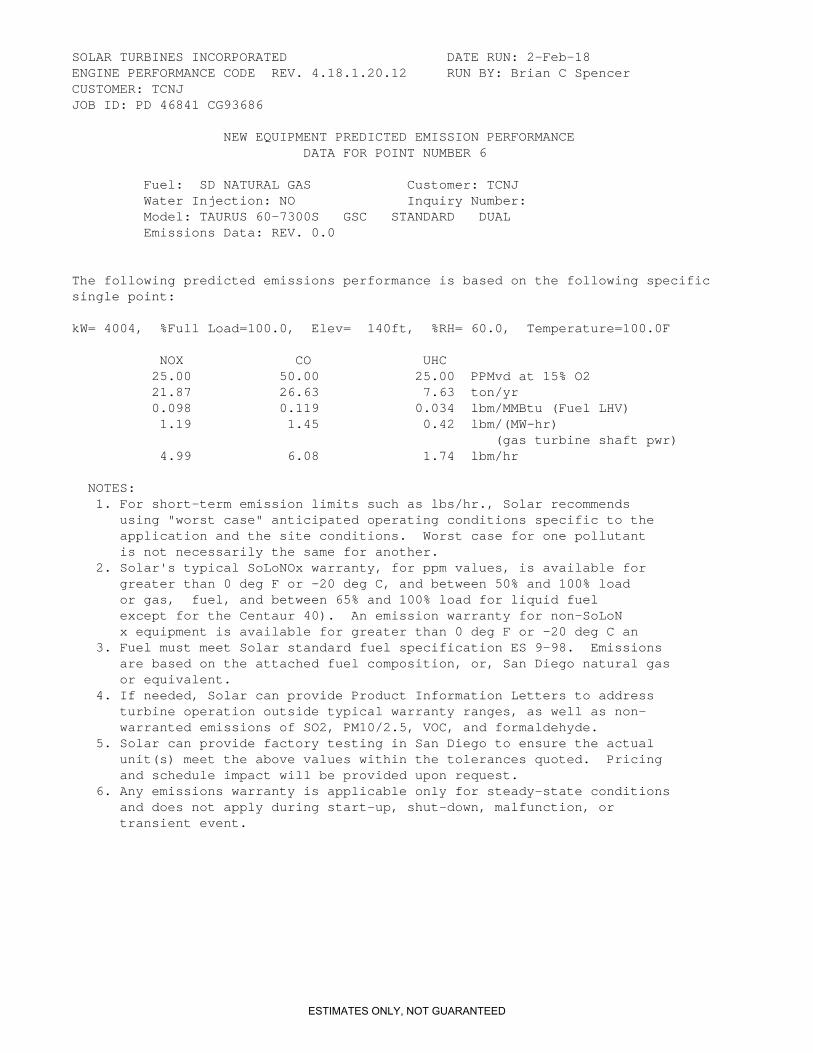
NEW EQUIPMENT PREDICTED EMISSION PERFORMANCE DATA FOR POINT NUMBER 6
Fuel: SD NATURAL GAS Customer: TCNJ Water Injection: NO Inquiry Number: Model: TAURUS 60-7300S GSC STANDARD DUAL Emissions Data: REV. 0.0
The following predicted emissions performance is based on the following specificsingle point:
kW= 4004, %Full Load=100.0, Elev= 140ft, %RH= 60.0, Temperature=100.0F
NOX CO UHC 25.00 50.00 25.00 PPMvd at 15% O2 21.87 26.63 7.63 ton/yr 0.098 0.119 0.034 lbm/MMBtu (Fuel LHV) 1.19 1.45 0.42 lbm/(MW-hr) (gas turbine shaft pwr) 4.99 6.08 1.74 lbm/hr
NOTES: 1. For short-term emission limits such as lbs/hr., Solar recommends using "worst case" anticipated operating conditions specific to the application and the site conditions. Worst case for one pollutant is not necessarily the same for another. 2. Solar's typical SoLoNOx warranty, for ppm values, is available for greater than 0 deg F or -20 deg C, and between 50% and 100% load or gas, fuel, and between 65% and 100% load for liquid fuel except for the Centaur 40). An emission warranty for non-SoLoN x equipment is available for greater than 0 deg F or -20 deg C an 3. Fuel must meet Solar standard fuel specification ES 9-98. Emissions are based on the attached fuel composition, or, San Diego natural gas or equivalent. 4. If needed, Solar can provide Product Information Letters to address turbine operation outside typical warranty ranges, as well as non- warranted emissions of SO2, PM10/2.5, VOC, and formaldehyde. 5. Solar can provide factory testing in San Diego to ensure the actual unit(s) meet the above values within the tolerances quoted. Pricing and schedule impact will be provided upon request. 6. Any emissions warranty is applicable only for steady-state conditions and does not apply during start-up, shut-down, malfunction, or transient event.
ESTIMATES ONLY, NOT GUARANTEED
SOLAR TURBINES INCORPORATED DATE RUN: 2-Feb-18ENGINE PERFORMANCE CODE REV. 4.18.1.20.12 RUN BY: Brian C SpencerCUSTOMER: TCNJJOB ID: PD 46841 CG93686
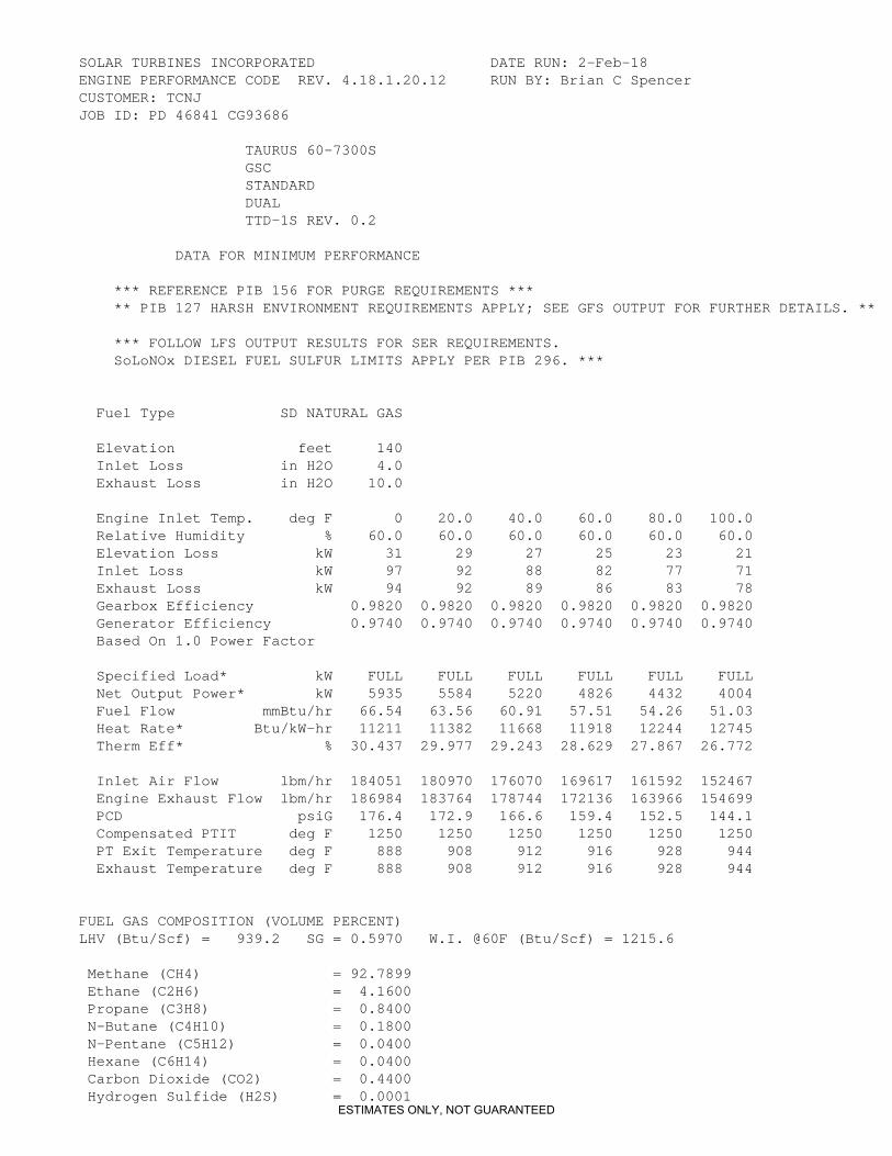
TAURUS 60-7300S GSC STANDARD DUAL TTD-1S REV. 0.2
DATA FOR MINIMUM PERFORMANCE
*** REFERENCE PIB 156 FOR PURGE REQUIREMENTS *** ** PIB 127 HARSH ENVIRONMENT REQUIREMENTS APPLY; SEE GFS OUTPUT FOR FURTHER DETAILS. **
*** FOLLOW LFS OUTPUT RESULTS FOR SER REQUIREMENTS. SoLoNOx DIESEL FUEL SULFUR LIMITS APPLY PER PIB 296. ***
Fuel Type SD NATURAL GAS
Elevation feet 140 Inlet Loss in H2O 4.0 Exhaust Loss in H2O 10.0
Engine Inlet Temp. deg F 0 20.0 40.0 60.0 80.0 100.0 Relative Humidity % 60.0 60.0 60.0 60.0 60.0 60.0 Elevation Loss kW 31 29 27 25 23 21 Inlet Loss kW 97 92 88 82 77 71 Exhaust Loss kW 94 92 89 86 83 78 Gearbox Efficiency 0.9820 0.9820 0.9820 0.9820 0.9820 0.9820 Generator Efficiency 0.9740 0.9740 0.9740 0.9740 0.9740 0.9740 Based On 1.0 Power Factor
Specified Load* kW FULL FULL FULL FULL FULL FULL Net Output Power* kW 5935 5584 5220 4826 4432 4004 Fuel Flow mmBtu/hr 66.54 63.56 60.91 57.51 54.26 51.03 Heat Rate* Btu/kW-hr 11211 11382 11668 11918 12244 12745 Therm Eff* % 30.437 29.977 29.243 28.629 27.867 26.772
Inlet Air Flow lbm/hr 184051 180970 176070 169617 161592 152467 Engine Exhaust Flow lbm/hr 186984 183764 178744 172136 163966 154699 PCD psiG 176.4 172.9 166.6 159.4 152.5 144.1 Compensated PTIT deg F 1250 1250 1250 1250 1250 1250 PT Exit Temperature deg F 888 908 912 916 928 944 Exhaust Temperature deg F 888 908 912 916 928 944
FUEL GAS COMPOSITION (VOLUME PERCENT)LHV (Btu/Scf) = 939.2 SG = 0.5970 W.I. @60F (Btu/Scf) = 1215.6
Methane (CH4) = 92.7899 Ethane (C2H6) = 4.1600 Propane (C3H8) = 0.8400 N-Butane (C4H10) = 0.1800 N-Pentane (C5H12) = 0.0400 Hexane (C6H14) = 0.0400 Carbon Dioxide (CO2) = 0.4400 Hydrogen Sulfide (H2S) = 0.0001
ESTIMATES ONLY, NOT GUARANTEED
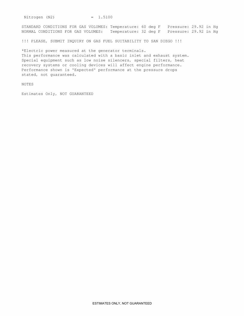
Nitrogen (N2) = 1.5100
STANDARD CONDITIONS FOR GAS VOLUMES: Temperature: 60 deg F Pressure: 29.92 in HgNORMAL CONDITIONS FOR GAS VOLUMES: Temperature: 32 deg F Pressure: 29.92 in Hg
!!! PLEASE, SUBMIT INQUIRY ON GAS FUEL SUITABILITY TO SAN DIEGO !!!
*Electric power measured at the generator terminals.This performance was calculated with a basic inlet and exhaust system. Special equipment such as low noise silencers, special filters, heat recovery systems or cooling devices will affect engine performance. Performance shown is "Expected" performance at the pressure drops stated, not guaranteed.
NOTES
Estimates Only, NOT GUARANTEED
ESTIMATES ONLY, NOT GUARANTEED
Burns Engineering, Inc. The College of New Jersey HRSG Renewal Rev: B
HEAT RECOVERY STEAM GENERATOR (HRSG) 235800 - 22
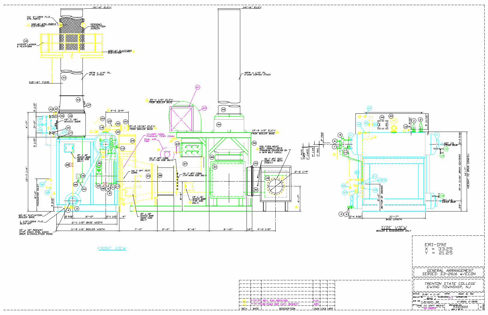
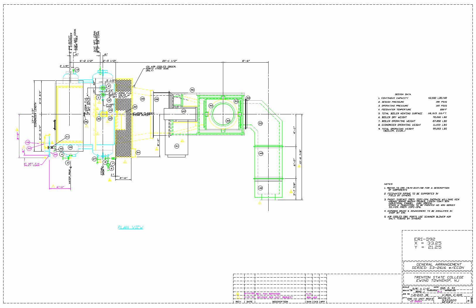
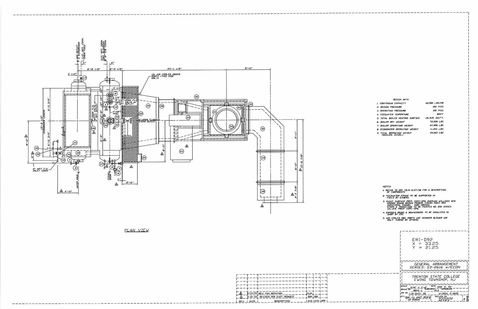
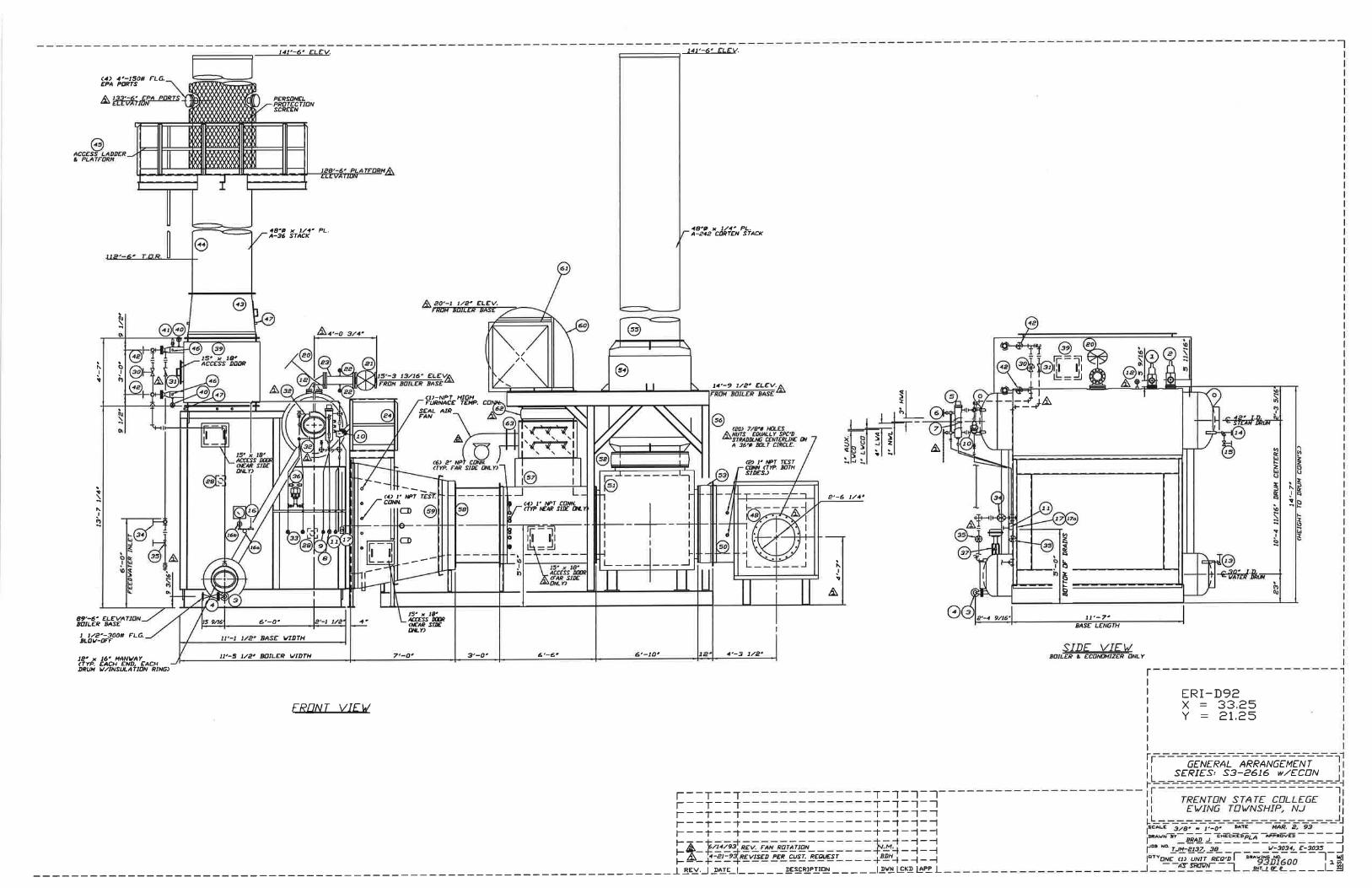
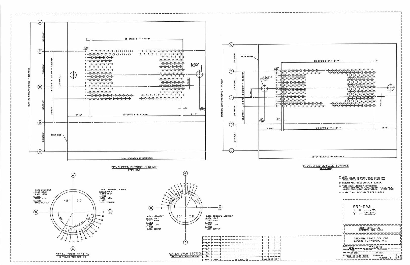
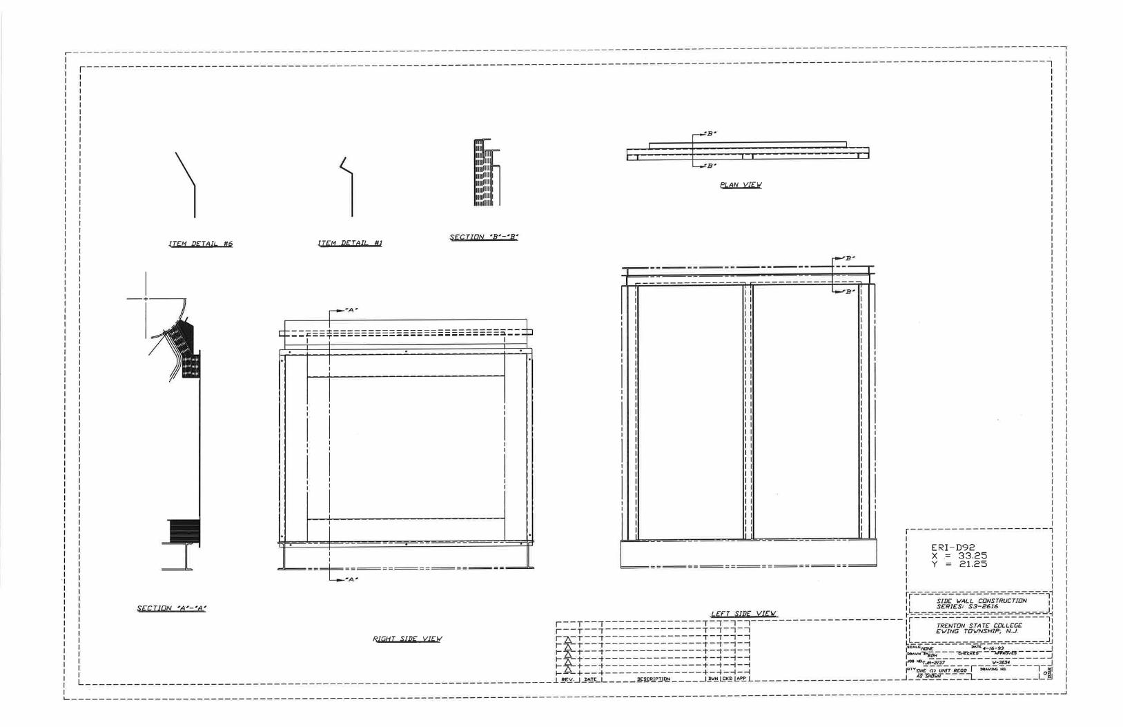
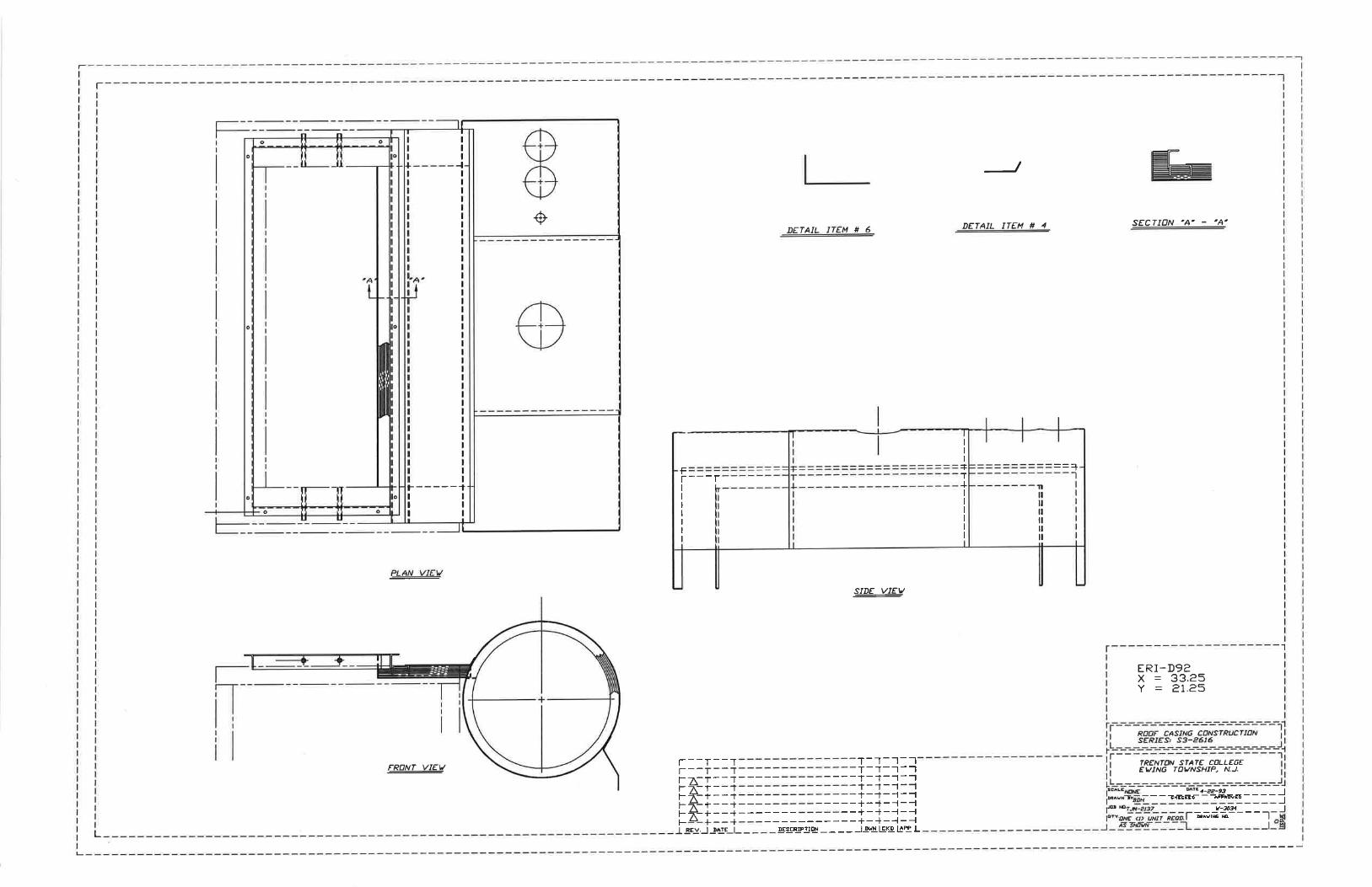
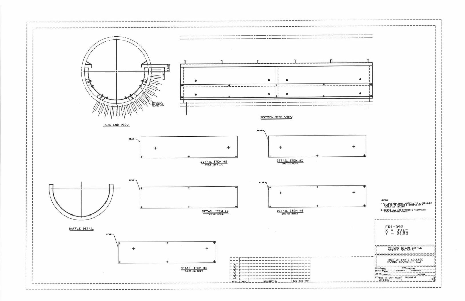
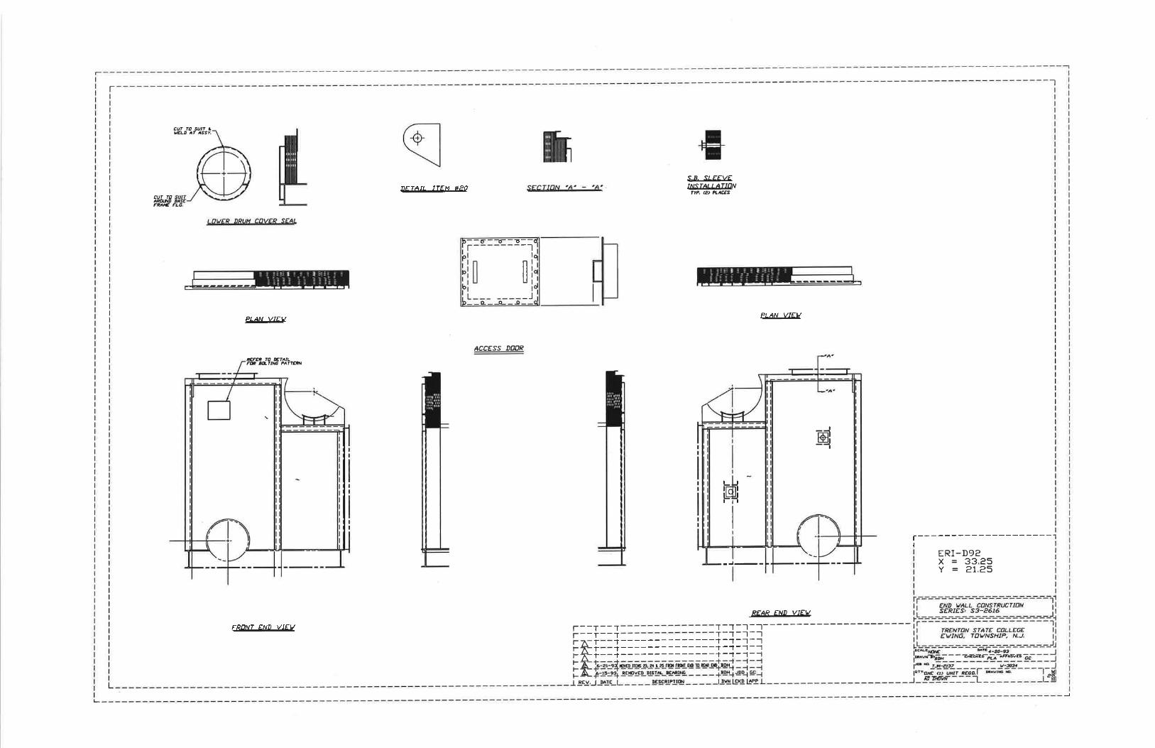
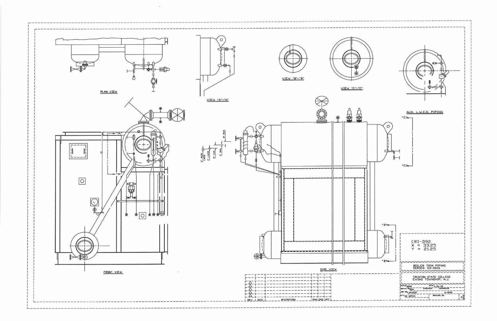
APPENDIX E
Energy Recovery International (ERI) drawings for Heat Recovery Steam Generator (HRSG)

KEY PLAN
Project Title:
Drawing Title:
Date:
Drawn:
Checked:
Job No:
Scale:
Drawing No:
ISSUED FOR BID
–
–
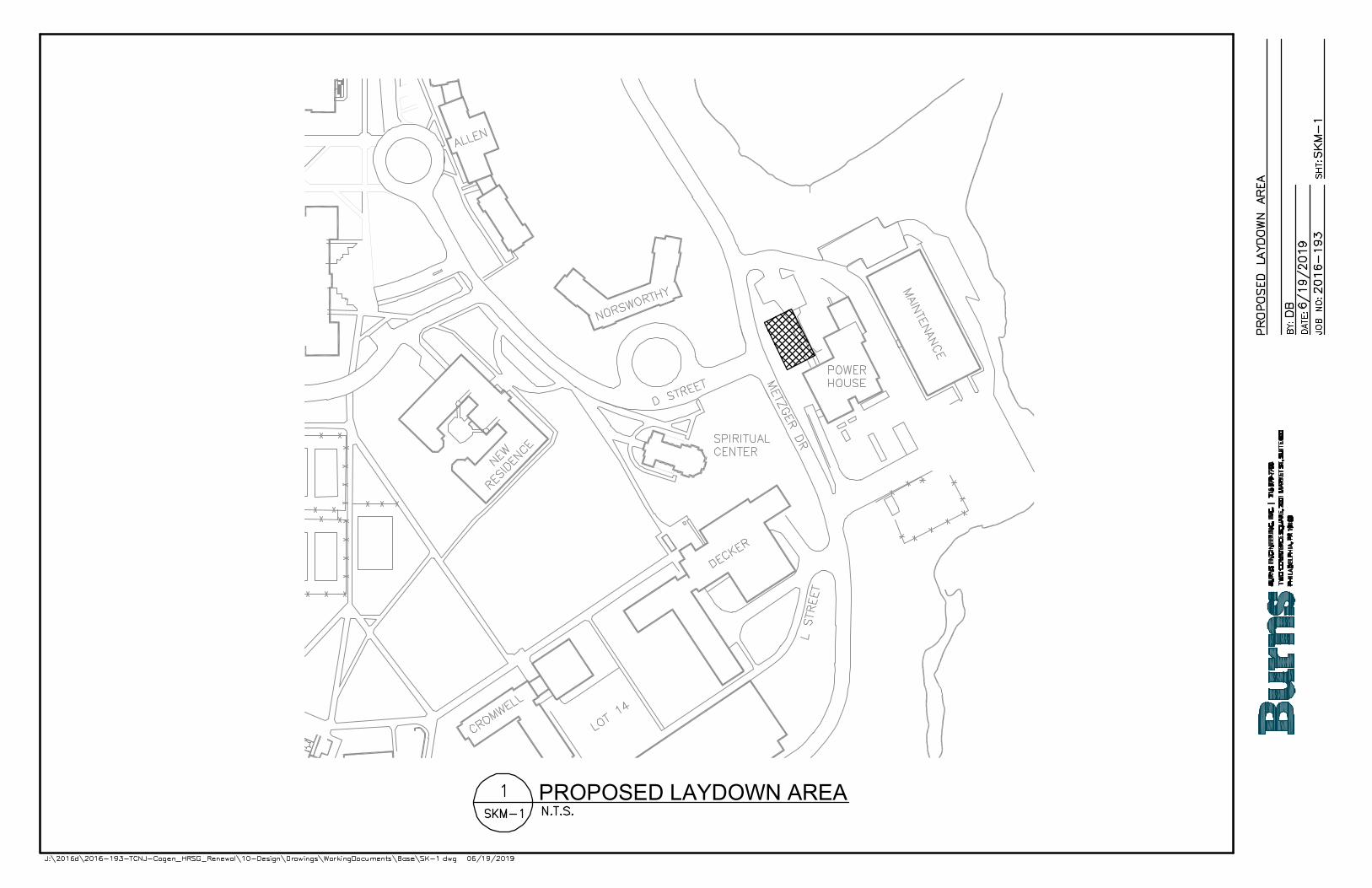
PROPOSED LAYDOWN AREA