Embed Size (px)
Citation preview

22 COMSOL NEWS
In recent years, 3D printing (additive manufacturing) has become a major player in research, design, and manufacturing work. Now the technology is also showing promise in the realm of material design. It will soon be commonplace to create prints with multiple materials and varying properties over a single object—a capability that will create a wealth of new applications with integrated products featuring highly tailored material properties. Additive manufacturing often uses small periodic microstructures in a repeating pattern to create the shape being built. A single microstructure is called a unit cell, and these may be as simple as triangles or honeycombs, or more complicated, with cross-struts and multiple voids between walls. Recent developments in 3D printing indicate that capabilities for multimaterial printing at the microlevel, where these microstructures can be combined and tailored to the designer’s needs, are rapidly expanding. This kind of fine control will allow engineers to choose the proportion and arrangement of each material included, giving them the freedom and flexibility to “design” performances that are impossible to achieve with a single material. Researchers at the Netherlands Organization for Applied Scientific Research (TNO) have begun investigating virtual material design, relying on multiphysics simulation and multiscale modeling to determine how specific properties could be effectively designed into a 3D-printed object. Work at the research institute spans many subjects, including safety and security,
energy, and manufacturing—the techniques used for optimizing material and topology in 3D-printed designs have been extended to their other areas of research, such as lightweight mechatronics, free-form solar cells, and lighting products.
èTHE STORY OF STRESS, STRAIN, AND STIFFNESS IN ANISOTROPIC MATERIALSAnisotropic materials behave differently depending on the direction they are loaded; however, with current methods of material production, control over the anisotropy is limited. Hence, any advantages are difficult to exploit for product design purposes. Marco Barink, researcher at TNO, set out to develop a procedure for designing manufacturable anisotropic structures using stiffness and topology optimization techniques. He began using the COMSOL Multiphysics® software to investigate a single unit cell intended to have twice the stiffness in one planar direction as the other (see Figure 1). “We were aiming for a desired stiffness matrix, so we applied a strain in COMSOL
and then optimized it to find the desired stress,” he explained. “We can tell COMSOL to make the material twice as stiff in one direction as another, and analyze the material behavior for a given geometry.” He verified the simulation results using a printed sample that he tested for the expected material behavior. After determining that his results were accurate, he performed a second optimization study for a highly anisotropic material. In this case, the simulation could control not only the spatial distribution of the material, but also the orientation of
TNO, NETHERLANDS
VIRTUAL MATERIAL DESIGN IN 3D PRINTING MAKES HEADWAY WITH MULTISCALE MODELINGResearchers at the Netherlands Organization for Applied Scientific Research (TNO)are using multiphysics simulation, multiscale modeling, and topology optimization to explore multimaterial 3D printing.
by LEXI CARVER
FIGURE 1. Top: Geometry of a unit cell. Middle: Simulation results showing mechanical stress for an optimized design with one planar direction having half the stiffness of the other. Bottom: 3D-printed samples.
COMSOL NEWS 23
the anisotropic fibers. With the larger goal in mind of designing properties beyond those available in a single material, the next step was to extend the simulation to structures comprising different material combinations, or multimaterials. Barink defined an anisotropic multimaterial cell in COMSOL, then optimized the local distribution of each material over a whole structure composed of a pattern of these cells (see Figure 2). He used the software to adjust the composition and arrangement until he reached the desired overall thermal conductivity.
èMULTISCALE MODELING AND COMPUTATIONAL HOMOGENIZATIONEach of these unit cells, in reality, would only be a tiny region in a final piece. After optimization at the microlevel, the TNO team began to study material optimization for larger-scale devices. “We’ve found that this microscale strategy works well for relatively small volumes,” said Erica Coenen, a research engineer at TNO. “However, to design real-life products, these need to be scaled up while maintaining feasible computation times. This is where so-called multiscale modeling comes in, giving the designer the tools to efficiently simulate at both the micromaterial scale and the product scale simultaneously.” Coenen implemented tools in
comparatively large complete OLED (tens of centimeters wide), the different length scales are difficult to account for in a single model. “Multiscale modeling is really the way to go forward,” Barink commented. With a new COMSOL study, they analyzed the grid shape to determine the ideal layout for improving light distribution. Combining a macromodel of the entire OLED with a micromodel of the honeycomb grid, they solved for effective light output and optimized the spacing and honeycomb dimensions (see Figure 3). Their updates to the existing
MULTIMATERIAL 3D PRINTING | MATERIALS SCIENCE
FIGURE 2. Barink’s simulation results showing optimized material composition (with three materials) for the desired anisotropic thermal conductivity. The simulation shows regions of high conductivity (white), low conductivity (orange), and a nonconductive material and voids (red). Several unit cells are arrayed periodically.
FIGURE 4. Left: Meshed model of a cell optimized for metal 3D printing. Right: Overview of the homogenized material properties for different cell designs.
FIGURE 3. Simulation results in the COMSOL® software showing the light output of an OLED. Top: Model including the hexagonal grid. Bottom: Macromodel with homogenized material properties.
COMSOL to extract parameters for the effective structural behavior of a single multimaterial cell. This effective behavior is used in a full-scale model, or macromodel, of a whole device. “We succeeded in creating a fully-coupled multiscale simulation—the macromodel contains homogeneous properties without any substructure details, and the micromodel contains the heterogeneous multimaterial microstructure. Many micromodels run within a single macromodel,” she explained. “We can consider multiple micromodels at once, solving for highly nonlinear and temperature-dependent behavior, based on local conditions from the macromodel.” Coenen and Barink applied a simplified version of this method to one of the major research topics at TNO, the development of large, flexible organic LEDs (OLEDs), which require the deposition of organic semiconductors onto flexible substrates. For good light homogeneity, these devices require careful design of the metal grids used in their transparent front-end electrodes; visible differences in light output create lighter and darker areas, which are undesirable for a final product. But directly modeling an OLED with a metal grid proved challenging in the past, due to large differences in the dimensions of different components. The honeycomb shapes that form the grid are only a few millimeters wide, and their metal edges 10 – 100 microns thick. Against the backdrop of the

24 COMSOL NEWS
design resulted in a 12% improvement in homogeneity without compromising efficiency in the OLED.
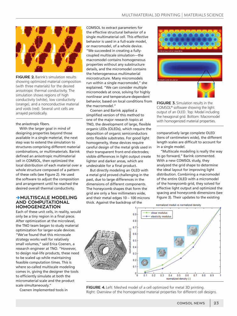
èBRINGING IT ALL TOGETHER: FROM SINGLE CELL TO COMPLETE PARTCoenen and Barink had demonstrated that topology optimization is a powerful tool for generating designs for additive manufacturing, given the capabilities of developing products that cannot be manufactured using conventional techniques. But even such a flexible manufacturing technology has some limitations. In one form of 3D printing called selective laser melting (SLM), the printer melts layers of powder into the desired shape. Unused powder must be removed from the object afterward, and large overhangs are usually avoided in SLM designs as they may warp. Therein lies a potential conflict: What happens when topology optimization creates an idealized design containing closed voids or large overhangs? “To circumvent this issue, our engineers came up with a few unit cells of different densities,” Barink remarked. “These cells are designed to be stiff, always printable, and contain holes so that the powder can be removed. Different unit cells combine to create the desired overall properties.” They then used COMSOL to analyze the relationship between material density and mechanical stiffness (see Figure 4). At the device level, it is not possible to handle a model with thousands of small 3D unit cells. So they combined their tested techniques: stiffness homogenization for each unit cell type followed by topology optimization at a larger level. “The homogenized properties of each unit cell serve as a separate material in the topology optimization at the device level,” Barink continued. For a concrete, less expensive example than a metal print, they applied the whole procedure to a polymer hammer handle (see Figure 5). The final design contains a combination of the different cell types, optimized by the software for the correct stiffness with minimal material use. “The hammer handle served as a demonstration of the power and Marco Barink (left) and Erica Coenen (right) standing with the 3D printer at TNO.
versatility of the whole procedure, going from design to final product,” Barink said. “From the design of unit cells, homogenization, topology optimization, generating printer input, and finally, printing, we have developed a good technique for designing a complete device with all the microlevel features. When applied to SLM designs, the techniques will address the typical production issues faced in metal printing, where stronger and more high-tech products are designed.”
The team at TNO had begun with a single cell and successfully built their way to anisotropic multimaterial microstructures. The application of their techniques to multiple areas of research at TNO demonstrated the power of combining simulation and multiscale modeling with innovative product development. This glimpse into the future, where multimaterial design may become the norm in additive manufacturing, would not have been possible without simulation. v
FIGURE 5. Left: Topology optimization result in the COMSOL® software. Center: The optimized hammer handle, printed in nylon. Right: Close-up of the pattern containing three different cell types: most dense cells with small holes near the top, least dense cells toward the bottom, and a few intermediate shapes in between.
MULTIMATERIAL 3D PRINTING | MATERIALS SCIENCE