Embed Size (px)
Citation preview

14 September 2007 1TMT.OPT.PRE.07.045.DRF01
Requirements and Conceptual Design of M2 System
Ben PlattMyung ChoMark Sirota
14 September 2007
14 September 2007 2TMT.OPT.PRE.07.045.DRF01
Outline
Ben Platt – Overview and System Requirements
Myung Cho – Modeling Conceptual Mirror Support Design
Mark Sirota – M2S Control Systems Overview

14 September 2007 3TMT.OPT.PRE.07.045.DRF01
Secondary Mirror System (M2S) Overview and System Requirements
Ben Platt
14 September
14 September 2007 4TMT.OPT.PRE.07.045.DRF01
Outline
M2 System Decomposition
External Interfaces
M2 System Description and Overview
M2 System Requirements
14 September 2007 5TMT.OPT.PRE.07.045.DRF01
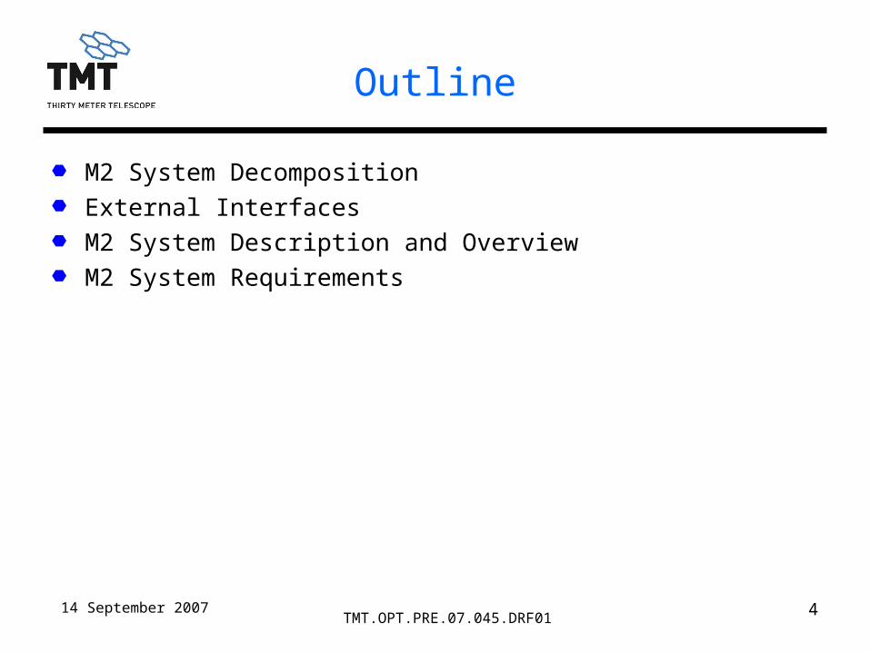
M2S Decomposition
M2 System (M2S) M2 Cell Assembly (M2CA)
– M2 Mirror (M2M) {blank and polishing}– M2 Support System (M2SS) {actuators, load cells, cabling}– M2 Cell (M2C) {cell structure}– M2 Control System - Cell (M2CSC) {electronics, software, sensors}
M2 Positioner Assembly (M2PA)– M2 Hexapod (M2H) {actuators, base, platform}– M2 Control System - Positioner (M2CSP) {electronics, software,
sensors}
M2 Interface Panel (M2I) {electrical/fluid interface with Telescope Structure}

14 September 2007 6TMT.OPT.PRE.07.045.DRF01
M2 External Interfaces
Draft Copies of the ICDs will be made available for this study.
14 September 2007 7TMT.OPT.PRE.07.045.DRF01
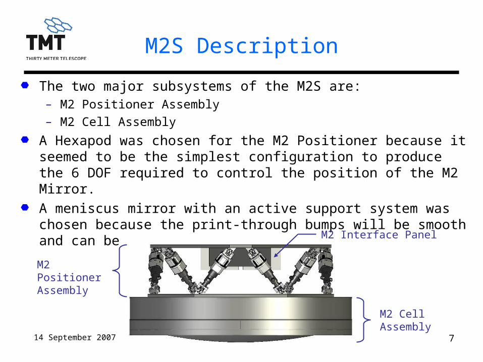
M2S Description
The two major subsystems of the M2S are:– M2 Positioner Assembly
– M2 Cell Assembly
A Hexapod was chosen for the M2 Positioner because it seemed to be the simplest configuration to produce the 6 DOF required to control the position of the M2 Mirror.
A meniscus mirror with an active support system was chosen because the print-through bumps will be smooth and can be corrected by adaptive Optics.
M2 Positioner Assembly
M2 Cell Assembly
M2 Interface Panel
14 September 2007 8TMT.OPT.PRE.07.045.DRF01
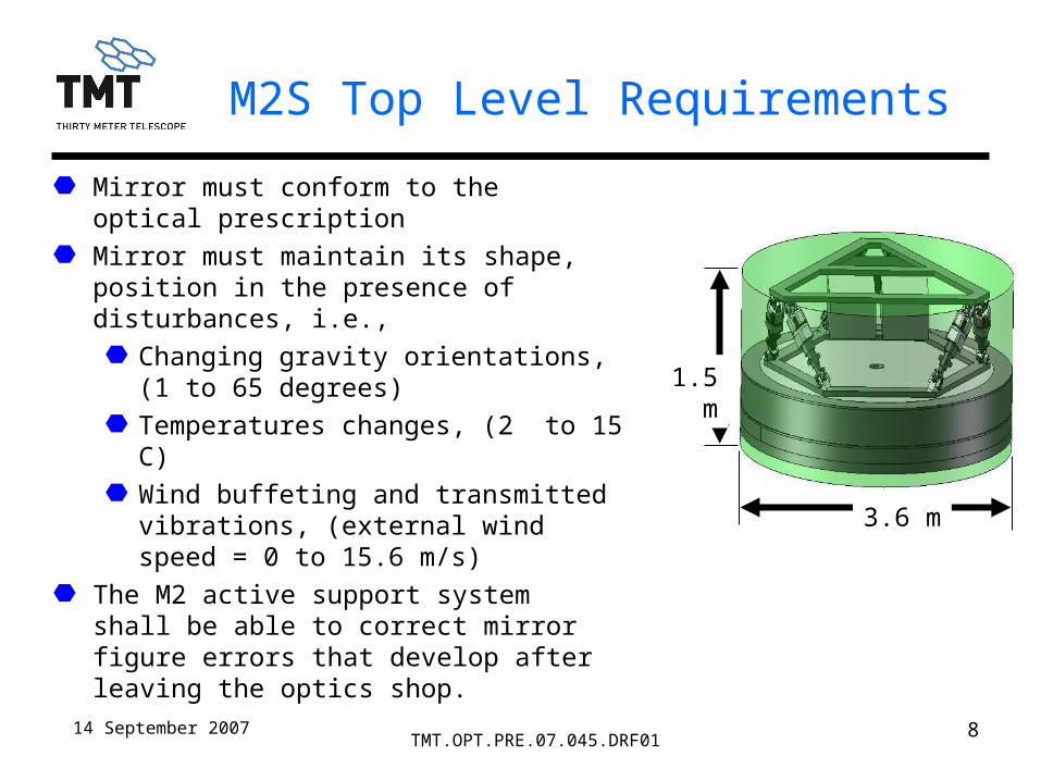
M2S Top Level Requirements
Mirror must conform to the optical prescription
Mirror must maintain its shape, position in the presence of disturbances, i.e.,
Changing gravity orientations, (1 to 65 degrees)
Temperatures changes, (2 to 15 C)
Wind buffeting and transmitted vibrations, (external wind speed = 0 to 15.6 m/s)
The M2 active support system shall be able to correct mirror figure errors that develop after leaving the optics shop.
3.6 m
1.5 m

14 September 2007 9TMT.OPT.PRE.07.045.DRF01
M2S Top Level Requirements
Mirror must maintain high reflectivity over a broad range of wavelengths (0.34 to 28 microns)System must be designed to be safe for personnel and equipment, (ORD*, Section 3.6)System must be reliable and maintainable, (ORD, Section 3.5)System must conform to interfaces and comply with mass and space envelope limits, (ICDs)**System must be compatible with observing environment
*ORD = Observatory Requirements Document**ICD = Interface Control Document

14 September 2007 10TMT.OPT.PRE.07.045.DRF01
M2S Top Level Requirements
Cross sectional area ≤ 5 m^2 perpendicular to the optical axis
Average Drag coefficient < 1.5
Total mass < 6000 kg.
Must incorporate alignment features for the Global Metrology System (GMS).
Relatively easy installation and removal of M2CA
Designed to allow CO2 cleaning, in situ washing

14 September 2007 11TMT.OPT.PRE.07.045.DRF01
M2 Cell Assembly (M2CA)
The M2CA consist of the Cell, Mirror and Support System
The M2 System shall maintain a set of Look-Up-Tables (LUT) storing actuator commands to correct for polishing errors as well as different gravitational and thermal deformations of the mirror surface.

14 September 2007 12TMT.OPT.PRE.07.045.DRF01
M2M Prescription and Dimensions
Material: Low Expansion Glass or Glass Ceramic
Clear Aperture: 3.048 m
Vertex Radius of Curvature: -6.22788 m
Conic Constant: -1.318228
Clear Aperture OD 3.024 m
ID 0.22 m

14 September 2007 13TMT.OPT.PRE.07.045.DRF01
M2M Polish Requirements
All figure requirements are with the mirror in the M2CA with the passive lateral and active axial supports.
The surface figure requirement is completely described with a normalized Structure Function based on a Kolmogorov atmosphere, with tip/tilt removed.

14 September 2007 14TMT.OPT.PRE.07.045.DRF01
M2M Structure Function
Parameters Calculated from the Structure Function are:
– RMS WFE: 204 nm
– Surface RMS Slope Error:0.403 µrad
– Surface P-V Slope Error: 1.45 µrad
Where:D(x) is the structure in units of (nm)2 A = Leading coefficient = 314626B = High frequency errors (surface roughness) = 2 nmx = Separation between point pairs, similar to spatial frequency.d = Diameter of beam footprint = 3.046 mr0 = Fried’s parameter = 2.88 m
2323
5
42.375.136.10 Bd
x
d
x
d
xAxD
35
0
230
2
500
r
mnmA
Where:
M2 SQRT(D(x))
0
50
100
150
200
250
300
350
400
0.000 0.200 0.400 0.600 0.800 1.000
x/d
Sq
ua
re r
oo
t o
f D
(x),
(n
m)

14 September 2007 15TMT.OPT.PRE.07.045.DRF01
M2 Mirror Support System (M2SS)
M2 must maintain its optical figure from zenith to 65 degrees zenith angle
M2 support system must be able to correct figure errors after mirror acceptance testing:– Optical test errors
– Temperature change
– Coating thickness & stress
Print-through bumps must be smooth (low frequency) so they are correctable by adaptive optics

14 September 2007 16TMT.OPT.PRE.07.045.DRF01
M2C Top Level Requirements
Support mass of actuators and mirror
Stiffness sufficient to allow M2S to have first resonant frequency > 15 Hz.
Provide structural interface for M2 Hexapod
Provide safety restraints for seismic and handling loads
Present minimum wind resistance
Maintenance: – Allow access for maintenance of actuators– Allow for ~ monthly CO2 cleaning and ~ semi-annual washing– Allow for periodic recoating of the mirror surface (Mirror must be easily removed
from cell.)
Seeing: – Must not deteriorate the telescope internal seeing, (Temperature difference
between mirror optical surface and ambient air shall be < 0.65 C (TBC).)
14 September 2007 17TMT.OPT.PRE.07.045.DRF01
M2 Support System (M2SS)Performance of NOAO Conceptual Design
Myung Cho

14 September 2007 18TMT.OPT.PRE.07.045.DRF01
Total of 60 axial supports on a four (4) concentric ring arrangement mounted at the mirror back surface Axial supports oriented parallel to the optical axis (vertical, Z-axis)Optimization for axial support forces in two (2) groups and for minimum surface RMS errorMirror substrate chosen to be solid meniscus 100 mm thick, to produce smooth print-through bumps that can be corrected by adaptive optics
Conceptual Axial support design
60 supports on 4 rings

14 September 2007 19TMT.OPT.PRE.07.045.DRF01
Axial support print-through: P-V = 49 nm surface; RMS = 10 nm surface
Axial support performance(mirror face down; gravity in local -Z)
Optimized axial support forces:
Ring 1 = 251 N; Ring 2,3,4 = 323 N

14 September 2007 20TMT.OPT.PRE.07.045.DRF01
Conceptual Lateral Support design
Lateral support: 24 passive systemEdge support concept– Schwesinger-like pattern– Equally spaced
Lateral support force constraints in optimization – No lateral force groups– Self equilibrium for lateral gravity– Minimum active force requirement
No support mount pads in analyses for lateral optimization – No mount pad weight – No lateral support linkage

14 September 2007 21TMT.OPT.PRE.07.045.DRF01
Lateral support layout:– 24 lateral supports around the
edge mounted on the mid-plane of M2
– Passive support (push/pull)
– Support force resultant in 3 directions (Fx, Fy, Fz)
– M2 assembly fits inside D=3.6m (outer diameter of envelope shown)
Lateral support system
D=3.6m envelope
14 September 2007 22TMT.OPT.PRE.07.045.DRF01
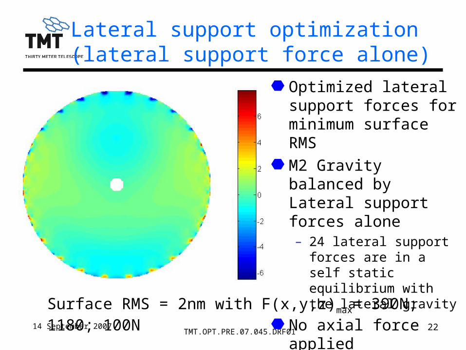
Lateral support optimization (lateral support force alone)
Surface RMS = 2nm with F(x,y,z)max= 390N; 1180; 100N
Optimized lateral support forces for minimum surface RMS
M2 Gravity balanced by Lateral support forces alone– 24 lateral support forces
are in a self static equilibrium with the lateral gravity
No axial force applied

14 September 2007 23TMT.OPT.PRE.07.045.DRF01
Natural frequency modes (first 10 mirror bending modes)
*First 10 mirror bending mode shapes are similar to low order Zernike polynomials
Mirror mass = 1934 Kg in the model
Natural frequencies and mode shapes (free-free)*
mode frequency mode shapeID (hz)
1 63.8 0 astigmatism 2 63.8 45 astigmatism 3 145.7 0 trefoil4 145.7 30 trefoil5 177.7 focus6 251.9 0 quadfoil7 251.9 45 quadfoil8 271.0 0 coma9 271.0 90 coma
10 381.0 pentafoil

14 September 2007 24TMT.OPT.PRE.07.045.DRF01
Active Optics Performance
Raw data Active Optics Correction aOZernike P-V rms P-V rms Fmax error
ID (nm) (nm) (nm) (nm) (N) (%)4 4715 1000 46.2 6.4 34.8 0.65 4825 1000 51.1 6.4 33.0 0.66 5506 1000 737.0 87.9 483.3 8.87 5506 1000 736.9 87.9 467.1 8.88 3337 1000 660.8 171.6 595.9 17.29 5535 1000 192.8 22.6 124.8 2.3
10 5535 1000 194.7 22.9 106.4 2.3
M2 active supports can correct low order Zernike modesFirst 10 Zernike modes (Z4 – Z10) were modeled with noise-free for a perfect system to determine to determine
– Residual RMS surface error from Reference surface RMS of 1000 nm– Maximum actuator force to correct Reference surface– aO error (residual RMS ÷ Reference RMS) or Gain (1/aO error)

14 September 2007 25TMT.OPT.PRE.07.045.DRF01
Typical Zernike Surfaces (FRINGE Zernikes)
Z04 Z07
Z08 Z10
Zernike ID. R(r,) Aberrations
4 r2 cos(2) astigmatism
5 r2 sin(2) astigmatism
6 (3r2 -2)r cos() coma
7 (3r2 -2)r sin() coma
8 6r4 - 6r2 + 1 asphere
9 r3 cos(3) trifoil
10 r3 sin(3) trifoil

14 September 2007 26TMT.OPT.PRE.07.045.DRF01
BACKUP
Myung Cho
14 September 2007 27TMT.OPT.PRE.07.045.DRF01
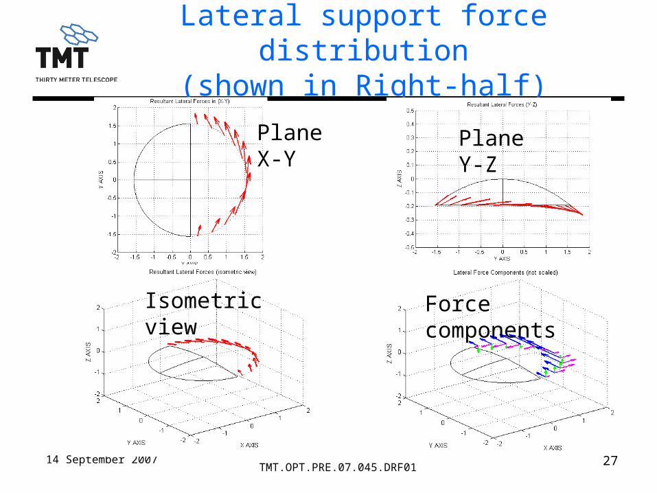
Lateral support force distribution(shown in Right-half)
Plane X-Y
Force componentsIsometric view
Plane Y-Z

14 September 2007 28TMT.OPT.PRE.07.045.DRF01
Lateral support force and direction (listed in Right-half)
force component (N) force direction (degree)Angle (o)
ID ANGLE Fx Fy Fz (X-Y)x (X-Y)y (Y-Z)y (Y-Z)z1 -82.5 97.88 400.76 97.15 76.28 13.72 13.63 76.372 -67.5 284.93 510.10 91.49 60.81 29.19 10.17 79.833 -52.5 388.60 682.25 77.03 60.33 29.67 6.44 83.564 -37.5 382.62 890.74 60.34 66.75 23.25 3.88 86.125 -22.5 280.62 1077.71 38.66 75.41 14.59 2.05 87.956 -7.5 108.32 1176.08 11.76 84.74 5.26 0.57 89.437 7.5 -108.32 1176.08 -11.76 95.26 5.26 0.57 90.578 22.5 -280.62 1077.71 -38.66 104.59 14.59 2.05 92.059 37.5 -382.62 890.74 -60.34 113.25 23.25 3.88 93.88
10 52.5 -388.60 682.25 -77.03 119.67 29.67 6.44 96.4411 67.5 -284.93 510.10 -91.49 119.19 29.19 10.17 100.1712 82.5 -97.88 400.76 -97.15 103.72 13.72 13.63 103.63

14 September 2007 29TMT.OPT.PRE.07.045.DRF01
Continue with Overview and System Requirements
Ben Platt

14 September 2007 30TMT.OPT.PRE.07.045.DRF01
M2 Hexapod Top Level Requirements
Quasi-Static Regime: – Provides static support of the M2CA over the elevation range of the telescope (0
to 90 degrees)– Capable of articulating the M2CA over 5 DOFs and maintain rotation about the
optical axis, with respect to the telescope structure, with high precision and repeatability.
Dynamic Regime: – Capable of moving quickly to a new position (slewing)– Don’t introduce vibrations to the telescope– Capable of moving in a smooth controlled trajectory at a commanded speed and
accelerationSeeing:
– The hexapod and it’s control electronics shall not degrade the seeing conditions, The heat emitted from the hexapod shall be less than TBD w. (Liquid coolant will be provided.)
Maintenance: – Designed for long life and high reliability– Components shall be designed for ease of service and maintenance, (Ability to
replace an actuator in the telescope.)
14 September 2007 31TMT.OPT.PRE.07.045.DRF01
M2 Interface Plate
TMT Will Provide an Interface Plate on the Telescope Structure for Connecting all Cables, Wires and Hoses.
14 September 2007 32TMT.OPT.PRE.07.045.DRF01
M2 Control System – Cell (M2CSC)
Mark Sirota

14 September 2007 33TMT.OPT.PRE.07.045.DRF01
M2 Control System-Cell
Summary Description & Requirements– The M2 Control System–Cell (M2CSC) provides local control for the M2 Cell
Assembly (M2CA). – The M2CSC is independent and separate from the M2 Control System-Positioner
(M2CSP).– The primary external M2CSC control interface is with the Telescope Control System
(TCS) via a single Ethernet connection.– The M2CSC will meet all performance requirements over the following conditions.
Zenith angles between 0 and 65 degrees
Zenith angle rates up to 30 arcseconds/seconds
Temperatures between 2 and 15 degrees C
– The M2CSC will be capable of maintaining the M2 mirror figure without requiring zenith angle or temperature data from the TCS at rates any faster than once every 100 seconds.
14 September 2007 34TMT.OPT.PRE.07.045.DRF01
M2 Control System-Cell
Summary Description & Requirements– The M2 Mirror shape will settle to its final shape within 15 seconds of the
completion of any move between zenith angles of 0 and 65 degrees.– “Cell Control” look up table (LUT)
Contains the set-points for each force actuator as a function of zenith angle and temperature.
The values contained in the Cell Control LUT are provided by the TCS.
Initial values for the Cell Control LUT will be developed during testing at the optics shop and supplied by the M2CA vendor.
Zenith angle and temperature are provided to the M2CSC by the TCS at a constant rate of ~ 0.1 Hz.
The M2CA won’t require complete calibration of the Cell Control LUT more frequently than once per year. Bias only corrections (zero point corrections) to the LUT will be allowed on a monthly time scale.

14 September 2007 35TMT.OPT.PRE.07.045.DRF01
M2 Control System - Cell
Summary Description & Requirements– Calibration and Diagnostics
The M2CSC will provide a telemetry stream that consists of parameters such as currents, sensor values, etc.
The M2CSC will include a diagnostic and calibration mode which supports
– control of individual actuators and the reading of individual sensors.
– support on-sky measurement of individual actuator influence functions
The M2CSC will have the capability of receiving and executing M2 Support command offsets from the TCS at rates up to once per second. (This will be used to gather data required to build a new Cell Control LUT)
– InterfacesControl and data transmission between the TCS and M2CSC will be via a single Ethernet connection.
All control, power, utility, utility interlocks, engineering sensor, and local control interfaces are via the M2 Interface Panel.
– E-Stop, Safety, Fault Handling, Alarms
14 September 2007 36TMT.OPT.PRE.07.045.DRF01
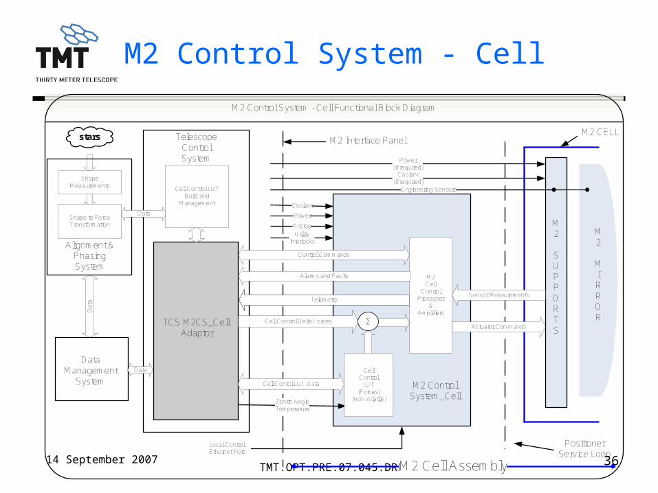
M2 Control System - Cell
M2
SUPPORTS
M2Cell
ControlProcessor
&Amplifiers
Cell Control Delta Forces
Zenith AngleTemperature
MIRROR
M2 CELL
Actuator Commands
Sensor MeasurementsTelemetry
Alarms and Faults
Control Commands
M2 Control System_Cell
M2 Interface Panel
E-Stop
Power
Coolant
PositionerService Loop
Power(if required)
Coolant(if required)
Local ControlEthernet Port
M2 Control System - Cell Functional Block Diagram
Σ
M2
MIRROR
CellControl
LUT(Forces)
(non volatile)
Engineering Sensors
Da
ta
Data
Cell Control LUTBuild and
Management
Cell Contol LUT Data
TelescopeControlSystem
TCS M2CS_Cell Adaptor
DataManagement
System
UtilityInterlocks
M2 Cell Assembly
ShapeMeasurements
Alignment &PhasingSystem
Shape to ForceTransformation
stars
Data
.
14 September 2007 37TMT.OPT.PRE.07.045.DRF01
M2 Control System – Positioner (M2CSP)
Mark Sirota
14 September 2007 38TMT.OPT.PRE.07.045.DRF01
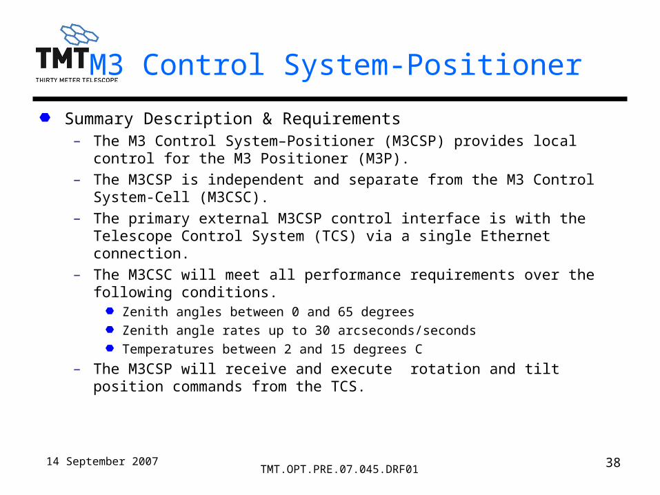
M3 Control System-Positioner
Summary Description & Requirements– The M3 Control System–Positioner (M3CSP) provides local control for the M3
Positioner (M3P). – The M3CSP is independent and separate from the M3 Control System-Cell
(M3CSC).– The primary external M3CSP control interface is with the Telescope Control
System (TCS) via a single Ethernet connection.– The M3CSC will meet all performance requirements over the following
conditions.Zenith angles between 0 and 65 degrees
Zenith angle rates up to 30 arcseconds/seconds
Temperatures between 2 and 15 degrees C
– The M3CSP will receive and execute rotation and tilt position commands from the TCS.
14 September 2007 39TMT.OPT.PRE.07.045.DRF01
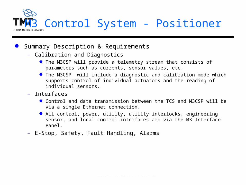
M3 Control System - Positioner
Summary Description & Requirements– Calibration and Diagnostics
The M3CSP will provide a telemetry stream that consists of parameters such as currents, sensor values, etc.
The M3CSP will include a diagnostic and calibration mode which supports control of individual actuators and the reading of individual sensors.
– InterfacesControl and data transmission between the TCS and M3CSP will be via a single Ethernet connection.
All control, power, utility, utility interlocks, engineering sensor, and local control interfaces are via the M3 Interface Panel.
– E-Stop, Safety, Fault Handling, Alarms

14 September 2007 40TMT.OPT.PRE.07.045.DRF01
M3 Control System - Positioner
Core performance characteristics– These numbers are representative and will be updated over the next several weeks.
Requirement Value Comment
Travel Range
Tilt +/- 8 degrees
Rotation +/- 180 degreesRepeatability
Tilt 1500 m-arcseconds
Rotation 3000 m-arcseconds
Piston 175 µ-meters RMSDifferential Accuracy
Tilt 200 m-arcseconds RMS
Rotation 200 m-arcseconds RMS
Piston 30 µ-meters peak
Max change in piston with simultaneos tilt and rotation
moves (< 15 arcseonds).Jitter
Tilt 100 m-arcseconds RMS
Rotation 100 m-arcseconds RMS
Piston 5 µ-meters RMS With trend removedTracking Speeds Tilt +/- 5 arcseconds/second Rotation +/-10 arcseconds/secondSlew Time < 2 minutesSettling Time < 10 seconds
Turnarounds can occur(tracking trough zero speed)
over 15 arcseconds
over the full travel range
Command minus M3 actual with trend removed

14 September 2007 41TMT.OPT.PRE.07.045.DRF01
M3 Control System - Positioner
.
M3Rotator/Tilt
ControlProcessor
&AmplifiersM3 Rotator Positions
Rotation & Tilt
Zenith angleTemperature
Telemetry
Alarms and Faults
Control Commands
M3 Control System-Positioner
M3 Interface Panel
E-Stop
PowerCoolant
M3 Cable Wrap
Power(if required)
Coolant(if required)
Local ControlEthernet Port
M3 Control System – Positioner Functional Block DiagramD
ata
AlignmentMeasurements
Data
M3 Positioner Control
stars TCS
TCS M3CS_P Adaptor
APS
DMS
UtilityInterlocks
M3 Positioner Assembly9/5/2007
.
.
M3
TILT
MECHANISM
Limit and Home Switches
Rotator Commands
M3
ROTATOR
Rotator & Tilt Commands
Rotator and Tilt Encoders
Engineering Sensors
Pointing Kernel
Positiondata
Transformation to delta
mechanical angle
Dat
a
Limit Switches

14 September 2007 42TMT.OPT.PRE.07.045.DRF01
Backup Slides

14 September 2007 43TMT.OPT.PRE.07.045.DRF01
M2M Polish WFE
Average WFE is determined from Nolls’ model of a Kolmogorov atmosphere
Equivalent Ro from:
D = 30 m aperture
– Convert to RMS wavefront error:
– WFE is independent of wavelength because Ro ~ λ6/5
WFE budget is matched to an atmospheric wavefront
To be further corrected by AO

14 September 2007 44TMT.OPT.PRE.07.045.DRF01
The equation below is a normalized structure function for a Kolmogorov atmosphere with tip tilt removed. Over a beam of diameter d the mean square phase variance at two points separated by a distance x is given by:
Structure Function Equation
22235
42.375.136.10 Bdx
dx
dx
AxD
•3

14 September 2007 45TMT.OPT.PRE.07.045.DRF01
M2 Structure Function Terms
The scaling factor A is a function of wavelength λ and the ratio of the telescope beam to Fried’s parameter ro:
Where: D(x) is the structure and it is in units of nm2
A = Leading coefficientB = Uncorrected wavefront errorx = Separation between point pairs,
similar to spatial frequencyd = Beam footprintr0 = Fried's Parameter
35
2 302
500
ormnmA

14 September 2007 46TMT.OPT.PRE.07.045.DRF01
M2M Polish Structure Function Curve
M2 SQRT(D(x))
0
50
100
150
200
250
300
350
400
0.000 0.200 0.400 0.600 0.800 1.000
x/d
Sq
ua
re r
oo
t o
f D
(x)

14 September 2007 47TMT.OPT.PRE.07.045.DRF01
Optical Coating Requirements

14 September 2007 48TMT.OPT.PRE.07.045.DRF01
Observing Operating Conditions