Embed Size (px)
Citation preview
TMS320F2810, TMS320F2811, and TMS320F2812 Flash APIs
Version 2.10
For creating custom programming solutions for the
TMS320F2810, TMS320F2811 and TMS320F2812 DSPs.
August 4, 2005
TMS320F281x Flash API Version 2.10
2 of 48
Flash API Disclaimer
The following Flash Application Program Interface (Flash API) libraries are included in this release:
Flash2810_API_V210.lib Flash2811_API_V210.lib Flash2812_API_V210.lib
Texas Instruments Inc. (TI) reserves the right to update or change any material included with this release. This includes:
The API functional behavior based on continued TMS320F2810, TMS320F2811, and TMS320F2812 testing.
Improvements in algorithm performance and functionality.
It is the user’s responsibility to check for future updates to these APIs and to use the latest version available for their TMS320F2810, TMS320F2811 or TMS320F2812 silicon. Should functional changes occur to the APIs, it is the user’s responsibility to update any application that uses the API (programmers, embedded software, etc) to insure proper long-term operation of the flash. Updates to the API will be posted on the Texas Instruments Inc website (www.ti.com) and can also be obtained by contacting a local TI representative or the TI Product Information Center.
In this document, the terms F281x, and TMS320F281x are used to refer to all flash devices within the family, i.e. TMS320F2810, TMS320F2811 and TMS320F2812.
TMS320F281x Flash API Version 2.00
3 of 48
Contents:
1. General Release Notes...................................................................................................................................4 2. V1.00 to V2.10 Migration Tips.........................................................................................................................7 3. API Revision vs. Silicon Revision ...................................................................................................................8 4. Introduction: Flash API Programming Fundamentals ...................................................................................10 5. Example Program .........................................................................................................................................11 6. Flash API Checklist .......................................................................................................................................12 7. Step 1: Modify Flash281x_API_Config.h ......................................................................................................13 8. Step 2: Include Flash281x_API_Library.h ....................................................................................................14 9. Step 3: Include the proper Flash API library .................................................................................................14 10. Step 4: Initialize PLL Control Register (PLLCR) ...........................................................................................14 11. Step 5: Copy the Flash API functions to Internal SARAM ............................................................................15 12. Step 6: Initialize Flash_CPUScaleFactor ......................................................................................................19 13. Step 7: Initialize the Callback Function Pointer ............................................................................................20 14. Step 8: Optional: Disable Global Interrupts ..................................................................................................22 15. Step 9: Rules for Callback, Interrupts, and Watchdog..................................................................................24 16. Step 10: Optional: Frequency and PLL Configuration Toggle Test ..............................................................25 17. Step 11: Optional: Unlock the Code Security Module (CSM) .......................................................................26 18. Step 12: API Reference ................................................................................................................................26
18.1. Data Type Conventions ........................................................................................................................26 18.2. API Function Naming Conventions and Function list ...........................................................................26 18.3. Flash status structure (FLASH_ST)......................................................................................................27 18.4. ToggleTest Function .............................................................................................................................28 18.5. Erase Function......................................................................................................................................30 18.6. Program Function .................................................................................................................................34 18.7. Verify Function......................................................................................................................................37 18.8. Version (in float) Function.....................................................................................................................39 18.9. Version (in Hex) Function .....................................................................................................................40 18.10. Depletion Recovery Function ...............................................................................................................41 18.11. Step 13: Return Status Values .............................................................................................................42
19. Code Size Requirements ..............................................................................................................................45 20. Files included in this release.........................................................................................................................48
TMS320F281x Flash API Version 2.10
4 of 48
1. General Release Notes
There is one flash API per each device within the TMS320F281x family. This list applies to the TMS320F2810, TMS320F2811 and TMS320F2812 APIs. a) Version 2.10 of the API is a mandatory update. All users of the TMS320F2810, TMS320F2811, and
TMS320F2812 Flash API must upgrade their flash programming system to use V2.10 of the Flash API. Flash API V2.10 is being released to accompany the change to TMS320F2810, TMS320F2811, and TMS320F2812 silicon revision G. Silicon revision G will require Flash API V2.10. Versions earlier than V2.00 of the Flash API will not operate correctly with revision G silicon.
Flash API V2.10 is fully backwards compatible with all previous TMS and TMP silicon revisions of TMS320F2810, TMS320F2811, and TMS320F2812. As with V1.00 of the Flash API, V2.10 of the Flash API will not work on TMX revisions prior to silicon revision C (i.e. silicon revisions 0, A and B). If you have additional questions after reviewing this documentation, please check the TMS320C2000 web site at http://www.ti.com/c2000, contact your local TI representative, or contact the Texas Instruments Product Information Center. Note: Version 2.00 of the Flash API was available for download for a short time during the week of July 18th 2005. Using V2.00 to program the OTP will disturb erased bits within sector J of the main flash array. For this reason, V2.00 of the API is now considered obsolete. Users who downloaded V2.00 should migrate to V2.10.
b) The Flash APIs have all been compiled with the large memory model (-ml) enabled. The small memory
model is not supported. Any application that uses the Flash API should also be compiled for the large memory model. For information on the large memory model refer to the TMS320C28x Optimizing C/C++ Compiler User’s Guide (literature #SPRU514).
c) Some traditional programming utilities have separate operations for “clear” or “pre-condition” and “erase”. These two operations have been combined into one operation referred to only as “erase”.
d) Note: The CSM will be permanently locked if the CSM password locations are loaded with all 0x0000 and the device is secured. During the erase API function, a sector clear (program all bits to 0x0000) is immediately followed by an erase operation without resetting the device. This will help avoid permanently locking the CSM. Do not program the CSM passwords with all 0x0000.
e) The intended use of the Flash API software is for development of custom flash programming methods. The
Flash API is used with ROM boot loading options such as parallel load 16/8, SCI and SPI modes, to transfer the flash programming code into the DSP.
f) For programming the TMS320F2810, TMS320F2811 or TMS320F2812 through the JTAG port, use the SDFlash programmer from TI 3rd Party vendor Spectrum Digital Inc. (www.spectrumdigital.com) or the Code Composer StudioTM Plug-in from TI.
TMS320F281x Flash API Version 2.00
5 of 48
Changes from V2.00 to V2.10
This list applies to the TMS320F2810, TMS320F2811 and TMS320F2812 APIs.
a) Fixed an issue where programming the OTP block would disturb erased bits within sector J of the main flash array.
Changes from V1.00 to V2.00
This list applies to the TMS320F2810, TMS320F2811 and TMS320F2812 APIs.
a) Added support for TMS320F2810, TMS320F2811 and TMS320F2812 silicon revision G. This API is also backward compatible and has been tested on revision C through revision G. Refer to Section 3 for information regarding silicon revision vs. API revision.
b) The timing of the program-verify and the erase-verify operations have been extended. This timing change will enhance the robustness of the programming operation for revision G silicon.
c) The new API improves the robustness of the low temperature erase function at zero degrees C. There are
no reliability issues with devices prior to revision G that are programmed with either API V1.00 or API V2.10. Erasing at zero degrees C with API V1.00 will, however, yield higher than expected fallout.
d) A callback function for the API can now be specified by the user. This specified function will be called at
appropriate times during the program, erase, verify, and depletion recovery algorithms. This function may be useful for transmitting status to a serial port or servicing an external watchdog timer. During execution of the callback function the flash and OTP are not available and cannot be accessed. Refer to section 13 for more information.
e) To improve system integration of the API, interrupts are now only blocked during time critical code. The
global interrupt masks (INTM, DBGM) and the XNMI configuration registers are saved before and restored after time critical code segments. During the time that interrupts are allowed the flash and OTP are not available for code execution or data fetches. Refer to section 14 for more information.
f) A depletion recovery API function has been added to allow users to attempt to recover a part that has bits
left in an over-erased (i.e. depleted) state. Depletion can occur if the erase algo is stopped (via debugger halt, device reset, system powered down, etc) before it executes to completion. See section 18.10 for a description of depletion and the depletion recovery API function.
g) Added two functions that return the current version number of the API. One function returns a decimal
encoded hex value and the other returns a floating point value. See section 18.8 and 18.9 for a description of these functions.
h) The error codes used in API V1.00 have been retained. The following error codes have been added:
STATUS_FAIL_PRECOMPACT
Within the erase function, a pre-compaction step of all sectors has been added to improve the robustness of the erase function. The error code STATUS_FAIL_PRECOMPACT was added for this portion of the erase algorithm.
STATUS_FAIL_INCORRECT_PARTID
The API now checks the PARTID register (memory address 0x0882) before executing. This prevents the API from executing on an incompatible part. For example, a TMS320F281x API cannot execute on the flash of a F280x device.
TMS320F281x Flash API Version 2.10
6 of 48
STATUS_FAIL_API_SILICON_MISMATCH
At the start of each API function, the content of a boot ROM location is checked to determine if it is ok to execute the given API version on that silicon. In the future, TI can change the content of this boot ROM location if an API becomes obsolete. This will prevent an old API from executing on the new silicon. Version 2.00 of the API looks for the value 0xFFFF in Boot ROM location 0x3FFFB9. If this error code occurs, verify that that the proper API version is being used. Check the TMS320C2000 web site at http://www.ti.com/c2000.
i) Internal to the API, the file structure has changed. Therefore, if customers have linked specific API files to
specific code sections the applications linker command file may need to be modified. The file structure was changed such that only functions called by the application will be included in the final .out file. The API memory usage information in section 19 includes a list of the files associated with various API functions.
j) Internal to the API some function names now have a device specific prefix attached. This was done to allow
linking of more then one API into a single application. Functions that are generic to the APIs are only linked once in this case. This will not affect normal usage of the API and no action is required.
TMS320F281x Flash API Version 2.00
7 of 48
2. V1.00 to V2.10 Migration Tips
This list applies to all of the TMS320F281x APIs.
a) The V1.00 function prototypes have been retained and are compatible with V2.10. Prototypes for compatible functions as well as new functions, such as depletion recovery and API version, are included in the Flash281x_API_Library.h file.
b) The V1.00 error codes have also been retained and are compatible with V2.10. Definitions of the all of the
API error codes are included in the Flash281x_API_Library.h file.
c) Interrupts are now only disabled during time critical code. During the time that interrupts are enabled, flash and OTP memory blocks are not available for code execution or data fetches. If an application relied on the V1.00 API to automatically set the global interrupt mask before an API function call, then the application may need to be modified to explicitly disable interrupts before calling the V2.10 API function. Otherwise an ISR located in flash or OTP may be inadvertently executed. See section 14 for more information.
d) The version number of the API library (.lib) is included in the filename of the library itself. If the filename has been used in the linker .cmd file, then the .cmd file will need to be updated to reflect the new API library name.
e) Updating to use the new API files:
Library file (lib): Include the new library file (.lib) in the applications project and
remove the old library.
F281x_API_Library.h: The V2.10 F281x_API_Library.h file should be used to include the new error codes, API function prototypes for new functions and the callback function pointer definition.
F281x_API_Config.h: Only cosmetic changes have been made to the
F281x_API_Config.h file. If you have customized either the V1.00 F281x_API_Library.h or F281x_API_Config.h file, make sure that the changes are carried over to the new versions of these files. In particular, check that the CPU speed configuration in F281x_API_Config.h is correct.
f) The ability to specify a callback function has been added to the API. If the callback function feature is not
going to be used by the application then it is best to explicitly set the function pointer (Flash_CallbackPtr) to NULL as described in section 13. Failure to initialize the callback function pointer can cause the code to branch to an undefined location.
g) A beta version of the V1.00 API with callback function capability was released to a limited number of users.
In the V1.00 callback beta API, the function name was static and could not be changed. To add flexibility, in V2.10 of the API you must specify a pointer to the function that the API will use as the callback function. Refer to section 13.
h) Internal to the API, the file structure has changed. Therefore, if users have linked specific API files to
specific code sections the applications linker command file may need to be modified. The structure was changed such that only functions called by the application will be included in the final .out file. The API memory usage information in section 19 includes a list of the files associated with various API functions.
i) To allow for new features, the code size of the API functions has increased. Refer to the API memory
usage information in section 19 for information on the code size requirements of the API.
TMS320F281x Flash API Version 2.10
8 of 48
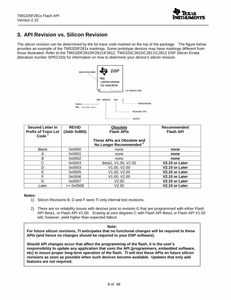
3. API Revision vs. Silicon Revision The silicon revision can be determined by the lot trace code marked on the top of the package. The figure below provides an example of the TMS320F281x markings. Some prototype devices may have markings different from those illustrated. Refer to the TMS320F2810\F2811\F2812, TMS320C2810\C2811\C2812 DSP Silicon Errata (literature number SPRZ193) for information on how to determine your device’s silicon revision.
Second Letter In Prefix of Trace Lot
Code 1
REVID (Addr 0x883)
Obsolete Flash APIs
These APIs are Obsolete and No Longer Recommended 2
Recommended Flash API
Blank 0x0000 none none A 0x0001 none none B 0x0002 none none C 0x0003 Beta1, V1.00, V2.00 V2.10 or Later D 0x0003 V1.00, V2.00 V2.10 or Later E 0x0005 V1.00, V2.00 V2.10 or Later F 0x0006 V1.00, V2.00 V2.10 or Later G 0x0007 V2.00 V2.10 or Later
Later >= 0x0008 V2.00 V2.10 or Later
Notes: 1) Silicon Revisions B, D and F were TI only internal test revisions.
2) There are no reliability issues with devices prior to revision G that are programmed with either Flash
API Beta1, or Flash API V1.00. Erasing at zero degrees C with Flash API Beta1 or Flash API V1.00 will, however, yield higher than expected fallout.
Note: For future silicon revisions, TI anticipates that no functional changes will be required to these APIs (and hence no changes should be required to your DSP software). Should API changes occur that affect the programming of the flash, it is the user’s responsibility to update any application that uses the API (programmers, embedded software, etc) to insure proper long-term operation of the flash. TI will test these APIs on future silicon revisions as soon as possible when such devices become available. Updates that only add features are not required.
TMS320F281x Flash API Version 2.00
9 of 48
The following APIs are obsolete and not recommended for use:
Version 2.00: F2812_API_V200.lib, F2811_API_V200.lib, F2810: F2810_API_V200.lib
Version 2.00 of the Flash API was available for download during the week of July 18th 2005. Using V2.00 to program the OTP will disturb erased bits within sector J of the main flash array. For this reason, V2.00 of the API is now considered obsolete. Users who downloaded V2.00 should migrate to V2.10.
Version 1.00: F2812_API_V100.lib, F2811_API_V100.lib, F2810: F2810_API_V100.lib
The TMS320F2810, TMS320F2811 and TMS320F2812 API V1.00 will not program or erase the flash as of Rev G silicon. If V1.00 of the API is run on a Rev G or later silicon, then the API will report one of the following error codes:
Erase: STATUS_FAIL_ERASE Program: STATUS_FAIL_ZERO_BIT_ERROR Verify: Verify will still operate as expected
The attempt to erase or program the flash will have no effect and no change will have been made to the contents of the flash. The only exception to this is if an attempt is made to program all zeros (0x0000) into the flash. In this case, the V1.00 API will incorrectly report that the programming operation successfully completed, however no change will have been made to the contents of the flash. This is a very unusual case and typically does not occur in a customer’s system.
Beta1: F2812_API_Beta1.lib, F2810_API_Beta1.lib
These APIs operated on REV C silicon only.
TMS320F281x Flash API Version 2.10
10 of 48
4. Introduction: Flash API Programming Fundamentals
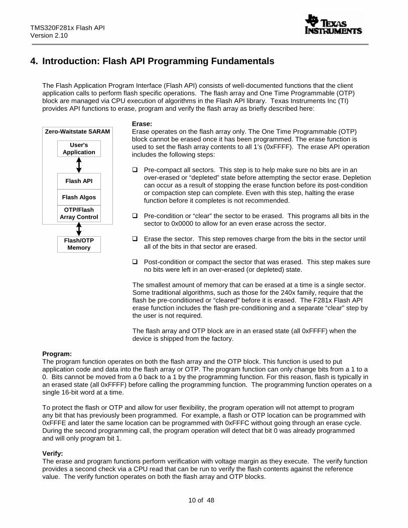
The Flash Application Program Interface (Flash API) consists of well-documented functions that the client application calls to perform flash specific operations. The flash array and One Time Programmable (OTP) block are managed via CPU execution of algorithms in the Flash API library. Texas Instruments Inc (TI) provides API functions to erase, program and verify the flash array as briefly described here:
Erase: Erase operates on the flash array only. The One Time Programmable (OTP) block cannot be erased once it has been programmed. The erase function is used to set the flash array contents to all 1’s (0xFFFF). The erase API operation includes the following steps:
Pre-compact all sectors. This step is to help make sure no bits are in an over-erased or “depleted” state before attempting the sector erase. Depletion can occur as a result of stopping the erase function before its post-condition or compaction step can complete. Even with this step, halting the erase function before it completes is not recommended.
Pre-condition or “clear” the sector to be erased. This programs all bits in the sector to 0x0000 to allow for an even erase across the sector.
Erase the sector. This step removes charge from the bits in the sector until all of the bits in that sector are erased.
Post-condition or compact the sector that was erased. This step makes sure no bits were left in an over-erased (or depleted) state.
The smallest amount of memory that can be erased at a time is a single sector. Some traditional algorithms, such as those for the 240x family, require that the flash be pre-conditioned or “cleared” before it is erased. The F281x Flash API erase function includes the flash pre-conditioning and a separate “clear” step by the user is not required. The flash array and OTP block are in an erased state (all 0xFFFF) when the device is shipped from the factory.
Program: The program function operates on both the flash array and the OTP block. This function is used to put application code and data into the flash array or OTP. The program function can only change bits from a 1 to a 0. Bits cannot be moved from a 0 back to a 1 by the programming function. For this reason, flash is typically in an erased state (all 0xFFFF) before calling the programming function. The programming function operates on a single 16-bit word at a time. To protect the flash or OTP and allow for user flexibility, the program operation will not attempt to program any bit that has previously been programmed. For example, a flash or OTP location can be programmed with 0xFFFE and later the same location can be programmed with 0xFFFC without going through an erase cycle. During the second programming call, the program operation will detect that bit 0 was already programmed and will only program bit 1.
Verify: The erase and program functions perform verification with voltage margin as they execute. The verify function provides a second check via a CPU read that can be run to verify the flash contents against the reference value. The verify function operates on both the flash array and OTP blocks.
User'sApplication
Flash API
Flash Algos
OTP/FlashArray Control
Flash/OTPMemory
Zero-Waitstate SARAM
TMS320F281x Flash API Version 2.00
11 of 48
To integrate one of the Flash APIs into your application you will need to follow steps described within this document. The checklist provided in section 6 gives an overview of the required steps and can be used to guide you through the process. While integrating the API, keep the following Do’s and Don’ts in mind:
API Do’s:
Execute the Flash API code from zero-wait state internal SARAM memory.
Configure the API for the correct CPU frequency of operation.
Follow the Flash API checklist in section 6 to integrate the API into an application.
Initialize the PLL control register (PLLCR) and wait for the PLL to lock before calling an API function.
Initialize the API callback function pointer (Flash_CallbackPtr). If the callback function is not going to be
used then it is best to explicitly set the function pointer to NULL as described in section 13. Failure to initialize the callback function pointer can cause the code to branch to an undefined location.
Carefully review the API restrictions for the callback function, interrupts, and watchdog described in
section 15. API Don’ts:
Don’t execute the flash API from wait stated memory such as XINTF.
Don’t execute the Flash APIs from the flash or OTP. If the APIs are stored in flash or OTP memory, they must first be copied to internal SARAM before they are executed.
Don’t execute any interrupt service routines (ISRs) that can occur during an erase, program or
depletion recovery API function from the flash or OTP memory blocks. Until the API function completes and exits the flash and OTP are not available for program execution or data storage.
Don’t execute the API callback function from flash or OTP. When the callback function is invoked by
the API during the erase, program or depletion recovery routine the flash and OTP are not available for program execution or data storage. Only after the API function completes and exits will the flash and OTP be available.
Don’t stop the erase, program or depletion recovery functions while they are executing (for example,
don’t stop the debugger within API code, don’t reset the part, etc).
Do not execute code or fetch data from the flash array or OTP while the flash and/or OTP is being erased, programmed or during depletion recovery.
5. Example Program
An example program that uses the Flash API has been included in this release. This example demonstrates how to interface to the API. The example is setup to be stored in the flash and the appropriate code and constants are copied to SARAM for execution.
TMS320F281x Flash API Version 2.10
12 of 48
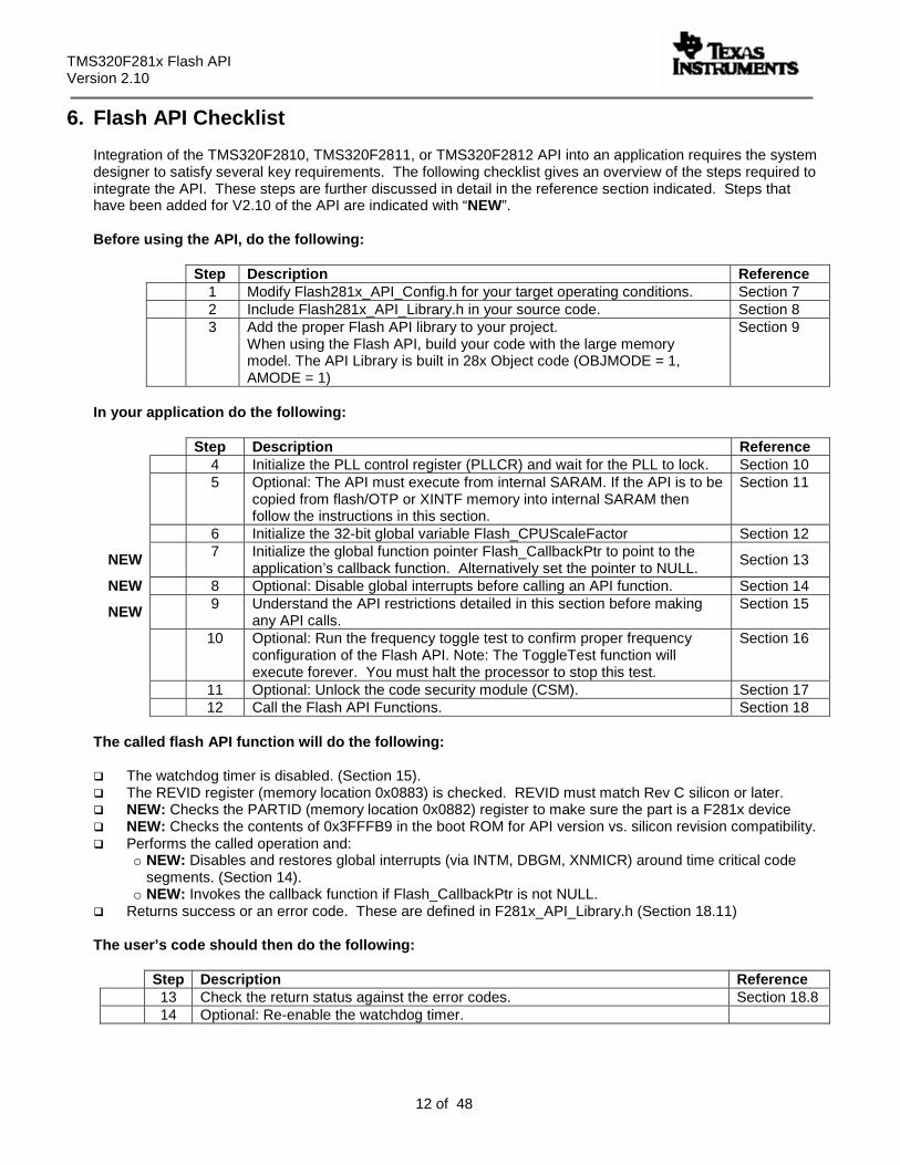
6. Flash API Checklist
Integration of the TMS320F2810, TMS320F2811, or TMS320F2812 API into an application requires the system designer to satisfy several key requirements. The following checklist gives an overview of the steps required to integrate the API. These steps are further discussed in detail in the reference section indicated. Steps that have been added for V2.10 of the API are indicated with “NEW”. Before using the API, do the following:
Step Description Reference 1 Modify Flash281x_API_Config.h for your target operating conditions. Section 7 2 Include Flash281x_API_Library.h in your source code. Section 8 3 Add the proper Flash API library to your project.
When using the Flash API, build your code with the large memory model. The API Library is built in 28x Object code (OBJMODE = 1, AMODE = 1)
Section 9
In your application do the following:
Step Description Reference
4 Initialize the PLL control register (PLLCR) and wait for the PLL to lock. Section 10 5 Optional: The API must execute from internal SARAM. If the API is to be
copied from flash/OTP or XINTF memory into internal SARAM then follow the instructions in this section.
Section 11
6 Initialize the 32-bit global variable Flash_CPUScaleFactor Section 12
NEW 7 Initialize the global function pointer Flash_CallbackPtr to point to the application’s callback function. Alternatively set the pointer to NULL.
Section 13
NEW 8 Optional: Disable global interrupts before calling an API function. Section 14
NEW 9 Understand the API restrictions detailed in this section before making any API calls.
Section 15
10 Optional: Run the frequency toggle test to confirm proper frequency configuration of the Flash API. Note: The ToggleTest function will execute forever. You must halt the processor to stop this test.
Section 16
11 Optional: Unlock the code security module (CSM). Section 17 12 Call the Flash API Functions. Section 18
The called flash API function will do the following:
The watchdog timer is disabled. (Section 15). The REVID register (memory location 0x0883) is checked. REVID must match Rev C silicon or later. NEW: Checks the PARTID (memory location 0x0882) register to make sure the part is a F281x device NEW: Checks the contents of 0x3FFFB9 in the boot ROM for API version vs. silicon revision compatibility. Performs the called operation and:
o NEW: Disables and restores global interrupts (via INTM, DBGM, XNMICR) around time critical code segments. (Section 14).
o NEW: Invokes the callback function if Flash_CallbackPtr is not NULL. Returns success or an error code. These are defined in F281x_API_Library.h (Section 18.11)
The user’s code should then do the following:
Step Description Reference
13 Check the return status against the error codes. Section 18.8 14 Optional: Re-enable the watchdog timer.
TMS320F281x Flash API Version 2.00
13 of 48
7. Step 1: Modify Flash281x_API_Config.h
Modify the Flash281x_API_Config.h file, found in the include directory, to match your specific target operating conditions. This file is used for the TMS320F2810, TMS320F2811 and TMS320F2812 APIs.
7.1. Specify the device.
This definition is used by the API main include file, Flash281x_API_Library.h, to conditionally compile in options specific to the TMS320F2810, TMS320F2811 and TMS320F2812 devices. These options include sector bit masks and macros that interface to the API functions.
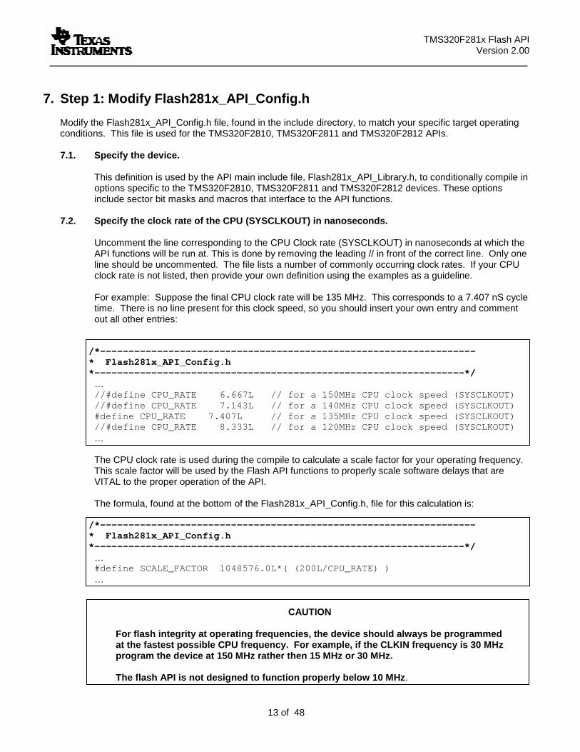
7.2. Specify the clock rate of the CPU (SYSCLKOUT) in nanoseconds.
Uncomment the line corresponding to the CPU Clock rate (SYSCLKOUT) in nanoseconds at which the API functions will be run at. This is done by removing the leading // in front of the correct line. Only one line should be uncommented. The file lists a number of commonly occurring clock rates. If your CPU clock rate is not listed, then provide your own definition using the examples as a guideline.
For example: Suppose the final CPU clock rate will be 135 MHz. This corresponds to a 7.407 nS cycle time. There is no line present for this clock speed, so you should insert your own entry and comment out all other entries:
/*------------------------------------------------------------------ * Flash281x_API_Config.h *-----------------------------------------------------------------*/
… //#define CPU_RATE 6.667L // for a 150MHz CPU clock speed (SYSCLKOUT) //#define CPU_RATE 7.143L // for a 140MHz CPU clock speed (SYSCLKOUT) #define CPU_RATE 7.407L // for a 135MHz CPU clock speed (SYSCLKOUT) //#define CPU_RATE 8.333L // for a 120MHz CPU clock speed (SYSCLKOUT) … The CPU clock rate is used during the compile to calculate a scale factor for your operating frequency. This scale factor will be used by the Flash API functions to properly scale software delays that are VITAL to the proper operation of the API. The formula, found at the bottom of the Flash281x_API_Config.h, file for this calculation is:
/*------------------------------------------------------------------ * Flash281x_API_Config.h
*-----------------------------------------------------------------*/ … #define SCALE_FACTOR 1048576.0L*( (200L/CPU_RATE) ) …
CAUTION For flash integrity at operating frequencies, the device should always be programmed
at the fastest possible CPU frequency. For example, if the CLKIN frequency is 30 MHz program the device at 150 MHz rather then 15 MHz or 30 MHz. The flash API is not designed to function properly below 10 MHz.
TMS320F281x Flash API Version 2.10
14 of 48
8. Step 2: Include Flash281x_API_Library.h
Flash281x_API_Library.h is the main include file for the Flash API and should be included in any application source file that interfaces to the Flash API. Flash281x_API_Library.h, is used for the TMS320F2810, TMS320F2811 and TMS320F2812 API libraries. Flash281x_API_Library.h contains the following:
Error code definitions. Refer to section 18.11.
Sector bit mask definitions that can be used when calling the erase function. Refer to Section 18.5.
Flash status structure (FLASH_ST) definition used by the API functions to return information back to the calling routine.
Function prototypes for each API library. Refer to section 18.
Frequency scale factor definition: Flash_CPUScaleFactor. Refer to section 12.
Pointer to callback function definition: Flash_CallbackPtr. Refer to section 13.
Macros to enable easy porting between the TMS320F2810, TMS320F2811 and TMS320F2812 API
libraries. Refer to section 18.2.
9. Step 3: Include the proper Flash API library
The proper Flash API library must also be included in your project. By default <> = C:\tidcs\c28
F2810: <>\Flash28_API\Flash2810_API_V210\lib\Flash2810_API_V210.lib F2811: <>\Flash28_API\Flash2811_API_V210\lib\Flash2811_API_V210.lib F2812: <>\Flash28_API\Flash2812_API_V210\lib\Flash2812_API_V210.lib
The Flash APIs have been compiled with the large memory model (-ml) option. The small memory model option is not supported. For information on the large memory model refer to the TMS320C28x Optimizing C/C++ Compiler User’s Guide (literature #SPRU514).
10. Step 4: Initialize PLL Control Register (PLLCR)
It is vital that the API functions be run at the proper operating frequency. To achieve this, the calling application must initialize the PLLCR register before calling any of the API functions. As part of this initialization, the calling application must guarantee through a software delay or other means that the PLL has had enough time to lock at the new frequency before making API calls. The PLL lock time required, as of Rev C silicon is 131072 cycles.
TMS320F281x Flash API Version 2.00
15 of 48
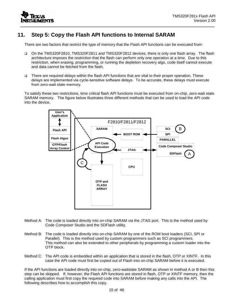
11. Step 5: Copy the Flash API functions to Internal SARAM There are two factors that restrict the type of memory that the Flash API functions can be executed from:
On the TMS320F2810, TMS320F2811 and TMS320F2812 devices, there is only one flash array. The flash architecture imposes the restriction that the flash can perform only one operation at a time. Due to this restriction, when erasing, programming, or running the depletion recovery algo, code itself cannot execute and data cannot be fetched from the flash.
There are required delays within the flash API functions that are vital to their proper operation. These
delays are implemented via cycle-sensitive software delays. To be accurate, these delays must execute from zero-wait state memory.
To satisfy these two restrictions, time critical flash API functions must be executed from on-chip, zero-wait state SARAM memory. The figure below illustrates three different methods that can be used to load the API code into the device.
SARAM
API CodeExecution
BOOT ROM
CPU
OTP andFLASHARRAY
JTAG
SCI
SPI
PARALLEL
User'sApplication
Flash API
Flash Algos
OTP/FlashArray Control
Code Composer Studio
SDFlash
F2810/F2811/F2812
A
B
C
Method A: The code is loaded directly into on-chip SARAM via the JTAG port. This is the method used by Code Composer Studio and the SDFlash utility.
Method B: The code is loaded directly into on-chip SARAM by one of the ROM boot loaders (SCI, SPI or
Parallel). This is the method used by custom programmers such as SCI programmers. This method can also be extended to other peripherals by programming a custom loader into the OTP block.
Method C: The API code is embedded within an application that is stored in the flash, OTP or XINTF. In this
case the API code must first be copied out of Flash into on-chip SARAM before it is executed.
If the API functions are loaded directly into on-chip, zero-waitstate SARAM as shown in method A or B then this step can be skipped. If, however, the Flash API functions are stored in flash, OTP or XINTF memory, then the calling application must first copy the required code into SARAM before making any calls into the API. The following describes how to accomplish this copy.
TMS320F281x Flash API Version 2.10
16 of 48
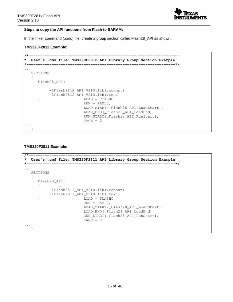
Steps to copy the API functions from Flash to SARAM: In the linker command (.cmd) file, create a group section called Flash28_API as shown. TMS320F2812 Example: /*------------------------------------------------------------------ * User’s .cmd file: TMS320F2812 API Library Group Section Example *-----------------------------------------------------------------*/ ...
SECTIONS { Flash28_API: { -lFlash2812_API_V210.lib(.econst) -lFlash2812_API_V210.lib(.text) } LOAD = FLASHC, RUN = RAML0, LOAD_START(_Flash28_API_LoadStart), LOAD_END(_Flash28_API_LoadEnd), RUN_START(_Flash28_API_RunStart), PAGE = 0
... }
TMS320F2811 Example: /*------------------------------------------------------------------ * User’s .cmd file: TMS320F2811 API Library Group Section Example *-----------------------------------------------------------------*/ ...
SECTIONS { Flash28_API: { -lFlash2811_API_V210.lib(.econst) -lFlash2811_API_V210.lib(.text) } LOAD = FLASHC, RUN = RAML0, LOAD_START(_Flash28_API_LoadStart), LOAD_END(_Flash28_API_LoadEnd), RUN_START(_Flash28_API_RunStart), PAGE = 0
... }
TMS320F281x Flash API Version 2.00
17 of 48
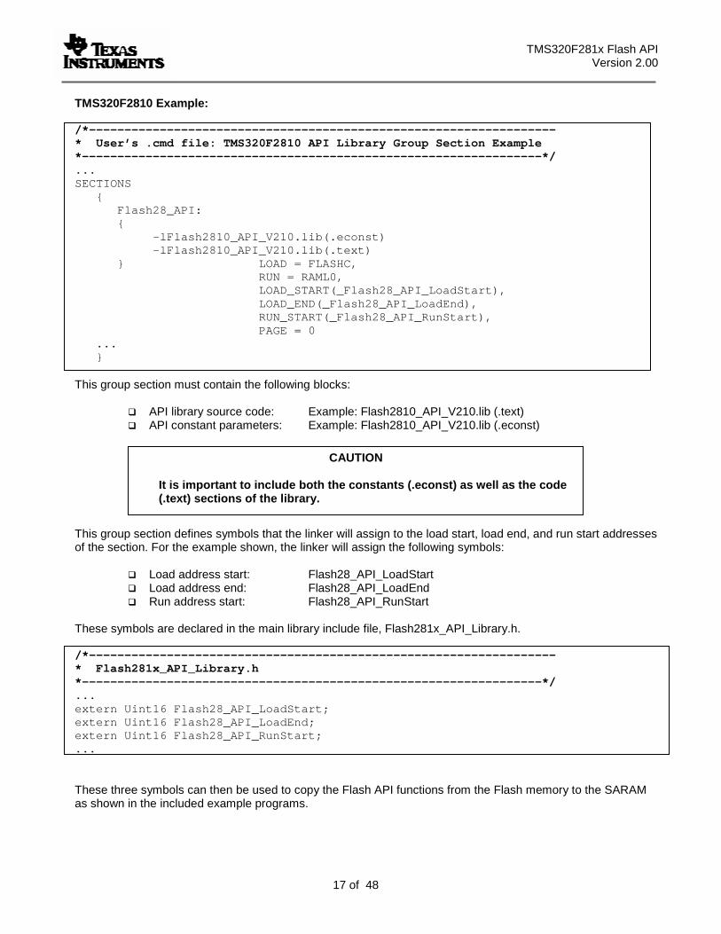
TMS320F2810 Example: /*------------------------------------------------------------------ * User’s .cmd file: TMS320F2810 API Library Group Section Example *-----------------------------------------------------------------*/ ... SECTIONS
{ Flash28_API: { -lFlash2810_API_V210.lib(.econst) -lFlash2810_API_V210.lib(.text) } LOAD = FLASHC, RUN = RAML0, LOAD_START(_Flash28_API_LoadStart), LOAD_END(_Flash28_API_LoadEnd), RUN_START(_Flash28_API_RunStart), PAGE = 0
... }
This group section must contain the following blocks:
API library source code: Example: Flash2810_API_V210.lib (.text) API constant parameters: Example: Flash2810_API_V210.lib (.econst)
This group section defines symbols that the linker will assign to the load start, load end, and run start addresses of the section. For the example shown, the linker will assign the following symbols:
Load address start: Flash28_API_LoadStart Load address end: Flash28_API_LoadEnd Run address start: Flash28_API_RunStart
These symbols are declared in the main library include file, Flash281x_API_Library.h. /*------------------------------------------------------------------ * Flash281x_API_Library.h *-----------------------------------------------------------------*/ ... extern Uint16 Flash28_API_LoadStart; extern Uint16 Flash28_API_LoadEnd; extern Uint16 Flash28_API_RunStart; ...
These three symbols can then be used to copy the Flash API functions from the Flash memory to the SARAM as shown in the included example programs.
CAUTION
It is important to include both the constants (.econst) as well as the code (.text) sections of the library.
TMS320F281x Flash API Version 2.10
18 of 48
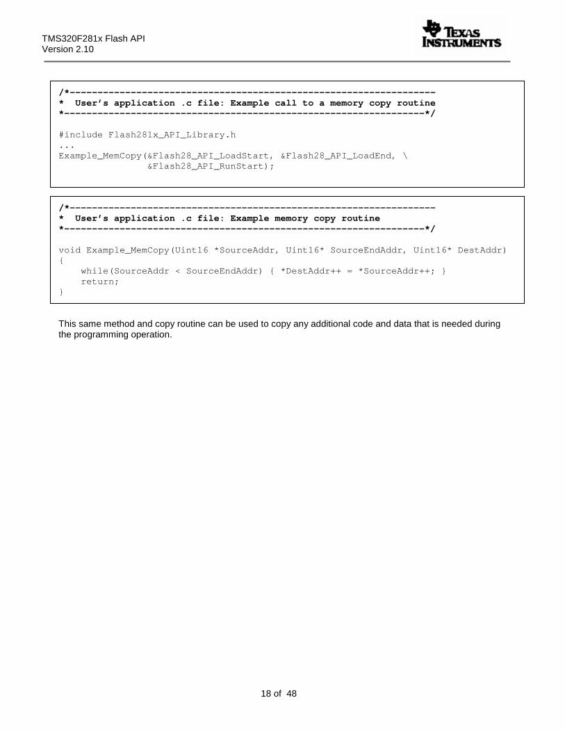
/*------------------------------------------------------------------ * User’s application .c file: Example call to a memory copy routine *-----------------------------------------------------------------*/ #include Flash281x_API_Library.h ... Example_MemCopy(&Flash28_API_LoadStart, &Flash28_API_LoadEnd, \ &Flash28_API_RunStart);
/*------------------------------------------------------------------ * User’s application .c file: Example memory copy routine *-----------------------------------------------------------------*/ void Example_MemCopy(Uint16 *SourceAddr, Uint16* SourceEndAddr, Uint16* DestAddr) { while(SourceAddr < SourceEndAddr) { *DestAddr++ = *SourceAddr++; } return;
}
This same method and copy routine can be used to copy any additional code and data that is needed during the programming operation.
TMS320F281x Flash API Version 2.00
19 of 48
CAUTION
It is strongly recommended that you test the CPU frequency and PLL configuration using the configuration toggle test described in section 16 before erasing or programming any parts. If this test fails, DO NOT PROCEED to erase or program the flash until the problem is corrected, or flash damage can occur.
CAUTION
The SCALE_FACTOR formula is already defined in the file Flash281x_API_Config.h. This formula must not be modified. Doing so will cause improper operation of the flash API functions.
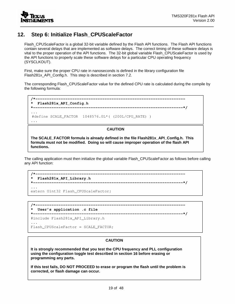
12. Step 6: Initialize Flash_CPUScaleFactor
Flash_CPUScaleFactor is a global 32-bit variable defined by the Flash API functions. The Flash API functions contain several delays that are implemented as software delays. The correct timing of these software delays is vital to the proper operation of the API functions. The 32-bit global variable Flash_CPUScaleFactor is used by the API functions to properly scale these software delays for a particular CPU operating frequency (SYSCLKOUT). First, make sure the proper CPU rate in nanoseconds is defined in the library configuration file Flash281x_API_Config.h. This step is described in section 7.2. The corresponding Flash_CPUScaleFactor value for the defined CPU rate is calculated during the compile by the following formula:
The calling application must then initialize the global variable Flash_CPUScaleFactor as follows before calling any API function:
/*----------------------------------------------------------------- * Flash281x_API_Config.h *-----------------------------------------------------------------*/ ... #define SCALE_FACTOR 1048576.0L*( (200L/CPU_RATE) ) ...
/*----------------------------------------------------------------- * Flash281x_API_Library.h *-----------------------------------------------------------------*/ ... extern Uint32 Flash_CPUScaleFactor;
/*----------------------------------------------------------------- * User’s application .c file *-----------------------------------------------------------------*/ #include Flash281x_API_Library.h ... Flash_CPUScaleFactor = SCALE_FACTOR;
TMS320F281x Flash API Version 2.10
20 of 48
CAUTION If the callback function feature is not used, then explicitly set the function pointer to NULL in the application code. Failure to explicitly initialize the callback function pointer can cause the code to branch to an undefined location. By default, the Flash_CallbackPtr is initialized to NULL as part of the compiler’s runtime initialization routine. If load time initialization is used or if the standard C initialization is bypassed the pointer will not be initialized and the code can branch to an undefined location. For this reason it is recommended that Flash_CallbackPtr always be explicitly initialized before calling the Flash API.
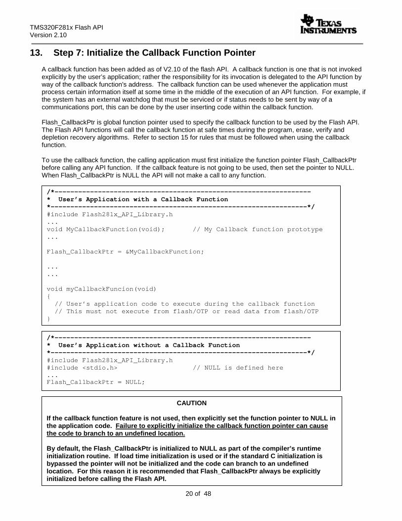
13. Step 7: Initialize the Callback Function Pointer
A callback function has been added as of V2.10 of the flash API. A callback function is one that is not invoked explicitly by the user’s application; rather the responsibility for its invocation is delegated to the API function by way of the callback function's address. The callback function can be used whenever the application must process certain information itself at some time in the middle of the execution of an API function. For example, if the system has an external watchdog that must be serviced or if status needs to be sent by way of a communications port, this can be done by the user inserting code within the callback function. Flash_CallbackPtr is global function pointer used to specify the callback function to be used by the Flash API. The Flash API functions will call the callback function at safe times during the program, erase, verify and depletion recovery algorithms. Refer to section 15 for rules that must be followed when using the callback function. To use the callback function, the calling application must first initialize the function pointer Flash_CallbackPtr before calling any API function. If the callback feature is not going to be used, then set the pointer to NULL. When Flash_CallbackPtr is NULL the API will not make a call to any function.
/*----------------------------------------------------------------- * User’s Application with a Callback Function *-----------------------------------------------------------------*/ #include Flash281x_API_Library.h ... void MyCallbackFunction(void); // My Callback function prototype ... Flash_CallbackPtr = &MyCallbackFunction; ... ... void myCallbackFuncion(void) { // User’s application code to execute during the callback function // This must not execute from flash/OTP or read data from flash/OTP }
/*----------------------------------------------------------------- * User’s Application without a Callback Function *-----------------------------------------------------------------*/ #include Flash281x_API_Library.h #include <stdio.h> // NULL is defined here ... Flash_CallbackPtr = NULL;
TMS320F281x Flash API Version 2.00
21 of 48
CAUTION During the callback function, the flash and OTP are not available for use by the application. Code cannot be executed from the flash/OTP nor can data be read from the flash/OTP. Flash and OTP will only again become available after the API function exits. Thus, the callback function must be executed completely outside of the flash/OTP and must not expect to read data from the flash/OTP. Attempting to execute from the flash will result in unknown opcode fetch and likely result in an illegal trap (ITRAP). Data fetched will be an unknown value.
During the callback function, the flash and OTP are in a safe state such that the callback function can take as much time as required to send status, service an external watchdog or perform other operations. However, flash and OTP are not available for execution of code or reading of data during this time. Refer to section 15 for rules that must be followed during the callback function.
TMS320F281x Flash API Version 2.10
22 of 48
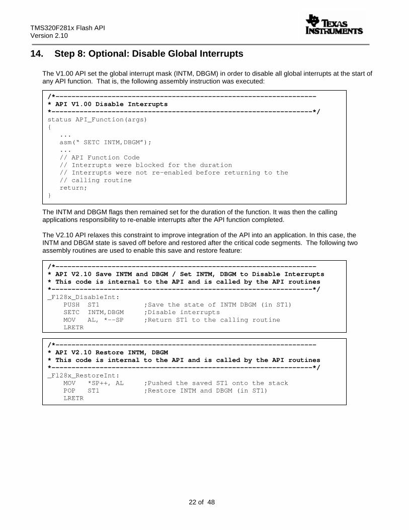
14. Step 8: Optional: Disable Global Interrupts
The V1.00 API set the global interrupt mask (INTM, DBGM) in order to disable all global interrupts at the start of any API function. That is, the following assembly instruction was executed:
The INTM and DBGM flags then remained set for the duration of the function. It was then the calling applications responsibility to re-enable interrupts after the API function completed. The V2.10 API relaxes this constraint to improve integration of the API into an application. In this case, the INTM and DBGM state is saved off before and restored after the critical code segments. The following two assembly routines are used to enable this save and restore feature:
/*----------------------------------------------------------------- * API V1.00 Disable Interrupts *-----------------------------------------------------------------*/ status API_Function(args) { ... asm(“ SETC INTM,DBGM”); ... // API Function Code // Interrupts were blocked for the duration // Interrupts were not re-enabled before returning to the // calling routine return; }
/*----------------------------------------------------------------- * API V2.10 Save INTM and DBGM / Set INTM, DBGM to Disable Interrupts * This code is internal to the API and is called by the API routines *-----------------------------------------------------------------*/ _Fl28x_DisableInt: PUSH ST1 ;Save the state of INTM DBGM (in ST1) SETC INTM,DBGM ;Disable interrupts MOV AL, *--SP ;Return ST1 to the calling routine LRETR
/*----------------------------------------------------------------- * API V2.10 Restore INTM, DBGM * This code is internal to the API and is called by the API routines *-----------------------------------------------------------------*/ _Fl28x_RestoreInt: MOV *SP++, AL ;Pushed the saved ST1 onto the stack POP ST1 ;Restore INTM and DBGM (in ST1) LRETR
TMS320F281x Flash API Version 2.00
23 of 48
CAUTION During the time that interrupts are enabled, the flash and OTP are not available for use by the application. Code cannot be executed from the flash/OTP nor can data be read from the flash/OTP. Flash and OTP will only again become available after the API function exits. Any ISR routines that are executed during an API function call must completely reside outside of the flash/OTP and must not expect to read data from the flash/OTP. Attempting to execute from the flash/OTP will result in undefined opcode fetch and likely result in an illegal trap (ITRAP). Data fetched will be an unknown value.
CAUTION – Migrating from V1.00 API If the application assumed that the API will automatically disable interrupts then the application may need to be updated to first disable global interrupts before calling the V2.10 API. Otherwise an unexpected ISR routine located in flash may inadvertently be called.
In addition to global interrupts, the XNMI interrupt is also disabled during time critical code. That is, the state of the XNMICR control register is saved and XNMI is disabled. After the time critical code, XNMICR is restored.
During the time that interrupts are enabled, the flash and OTP are in a safe state such that an interrupt service routine (ISR) can take as much time as required to service the interrupt. Flash and OTP are not available for execution of code or reading of data during this time. Refer to section 15 for rules that must be followed when interrupts are allowed during API function calls.
/*----------------------------------------------------------------- * API V2.10 Save/Restore XNMICR * This code is internal to the API routines *-----------------------------------------------------------------*/ #define XNMICR (volatile Uint16*)0x00007077 // XNMI Control Uint16 XnmiCr; ... XnmiCr = *XNMICR; // Save XNMICR *XNMICR = *XNMICR & 0xFFFE // Disable XNMI ... // Time critical API code ... *XNMICR = XnmiCR; // Restore XNMICR
TMS320F281x Flash API Version 2.10
24 of 48
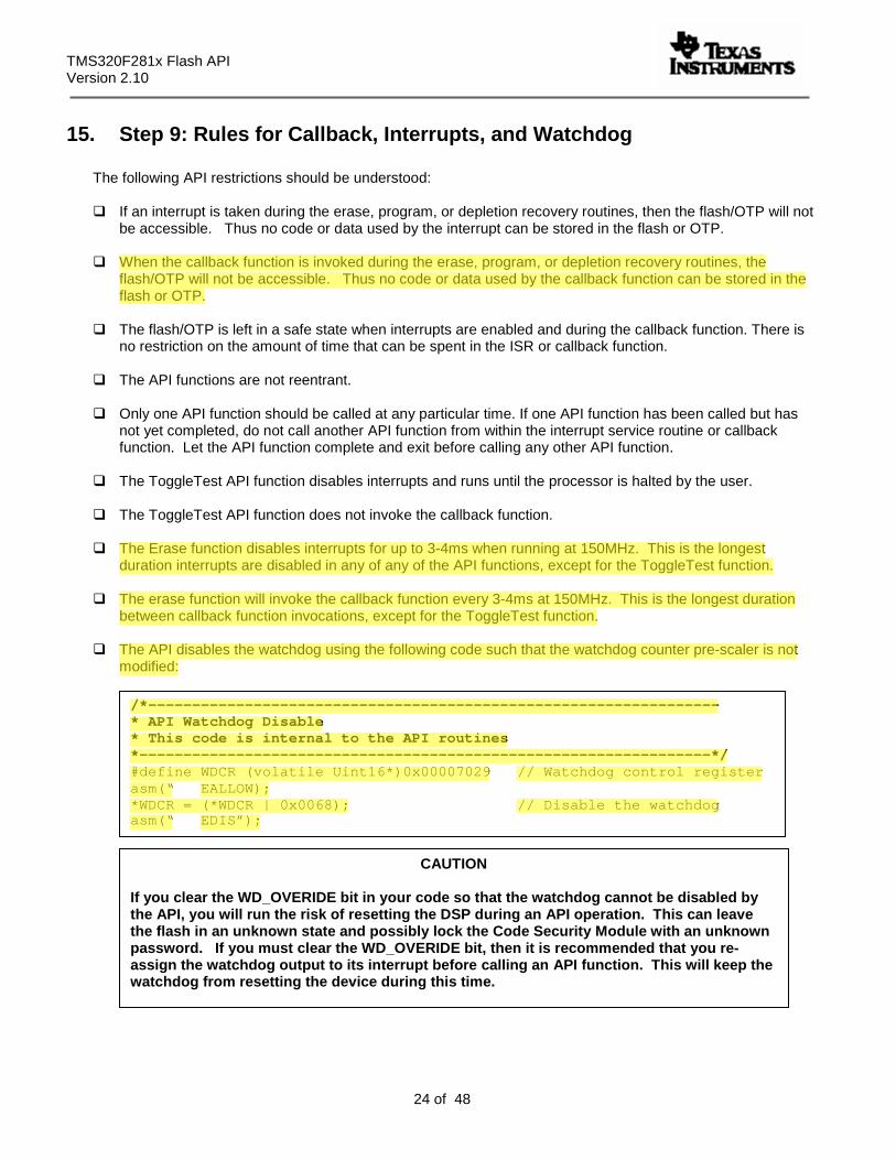
CAUTION If you clear the WD_OVERIDE bit in your code so that the watchdog cannot be disabled by the API, you will run the risk of resetting the DSP during an API operation. This can leave the flash in an unknown state and possibly lock the Code Security Module with an unknown password. If you must clear the WD_OVERIDE bit, then it is recommended that you re-assign the watchdog output to its interrupt before calling an API function. This will keep the watchdog from resetting the device during this time.
15. Step 9: Rules for Callback, Interrupts, and Watchdog
The following API restrictions should be understood:
If an interrupt is taken during the erase, program, or depletion recovery routines, then the flash/OTP will not be accessible. Thus no code or data used by the interrupt can be stored in the flash or OTP.
When the callback function is invoked during the erase, program, or depletion recovery routines, the
flash/OTP will not be accessible. Thus no code or data used by the callback function can be stored in the flash or OTP.
The flash/OTP is left in a safe state when interrupts are enabled and during the callback function. There is
no restriction on the amount of time that can be spent in the ISR or callback function.
The API functions are not reentrant.
Only one API function should be called at any particular time. If one API function has been called but has not yet completed, do not call another API function from within the interrupt service routine or callback function. Let the API function complete and exit before calling any other API function.
The ToggleTest API function disables interrupts and runs until the processor is halted by the user.
The ToggleTest API function does not invoke the callback function.
The Erase function disables interrupts for up to 3-4ms when running at 150MHz. This is the longest
duration interrupts are disabled in any of any of the API functions, except for the ToggleTest function.
The erase function will invoke the callback function every 3-4ms at 150MHz. This is the longest duration between callback function invocations, except for the ToggleTest function.
The API disables the watchdog using the following code such that the watchdog counter pre-scaler is not
modified:
/*----------------------------------------------------------------- * API Watchdog Disable * This code is internal to the API routines *-----------------------------------------------------------------*/ #define WDCR (volatile Uint16*)0x00007029 // Watchdog control register asm(“ EALLOW); *WDCR = (*WDCR | 0x0068); // Disable the watchdog asm(“ EDIS”);
TMS320F281x Flash API Version 2.00
25 of 48
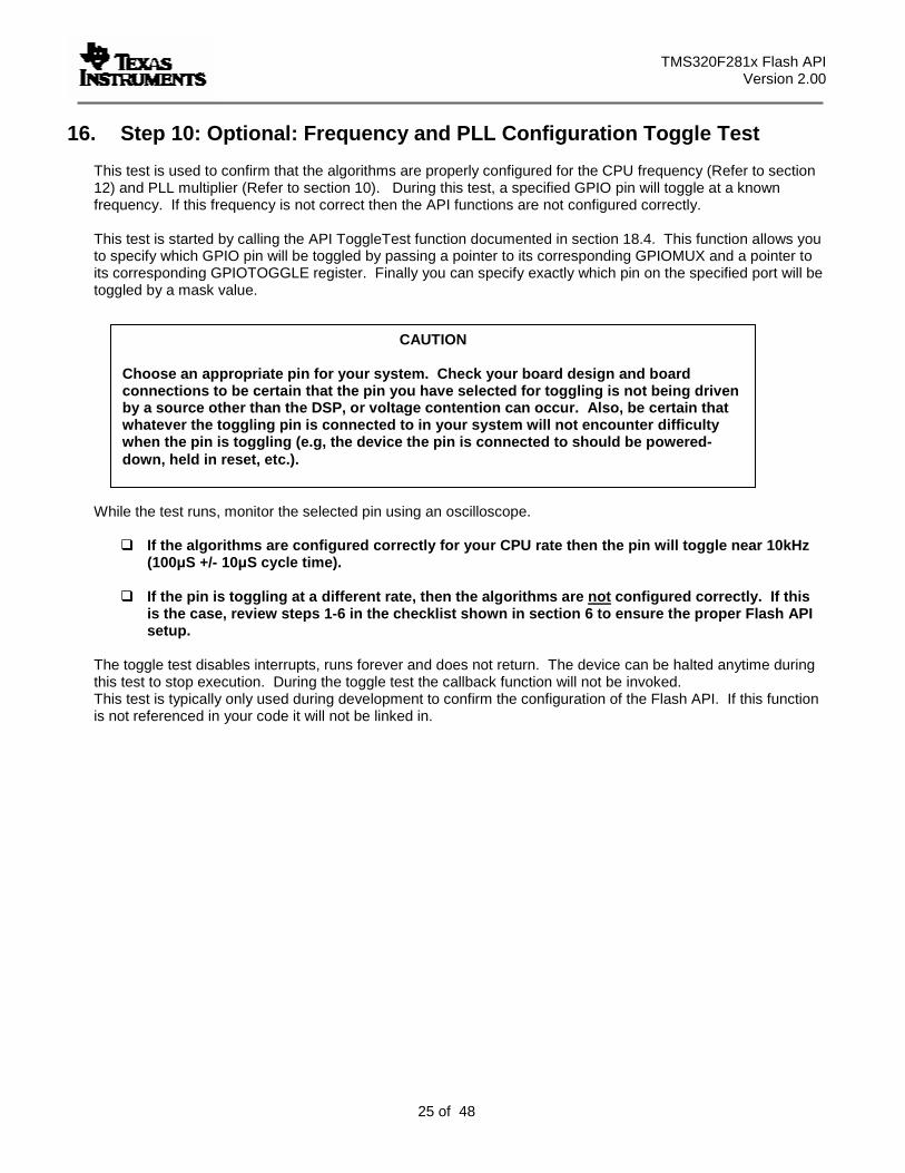
CAUTION
Choose an appropriate pin for your system. Check your board design and board connections to be certain that the pin you have selected for toggling is not being driven by a source other than the DSP, or voltage contention can occur. Also, be certain that whatever the toggling pin is connected to in your system will not encounter difficulty when the pin is toggling (e.g, the device the pin is connected to should be powered-down, held in reset, etc.).
16. Step 10: Optional: Frequency and PLL Configuration Toggle Test
This test is used to confirm that the algorithms are properly configured for the CPU frequency (Refer to section 12) and PLL multiplier (Refer to section 10). During this test, a specified GPIO pin will toggle at a known frequency. If this frequency is not correct then the API functions are not configured correctly. This test is started by calling the API ToggleTest function documented in section 18.4. This function allows you to specify which GPIO pin will be toggled by passing a pointer to its corresponding GPIOMUX and a pointer to its corresponding GPIOTOGGLE register. Finally you can specify exactly which pin on the specified port will be toggled by a mask value.
While the test runs, monitor the selected pin using an oscilloscope.
If the algorithms are configured correctly for your CPU rate then the pin will toggle near 10kHz (100µS +/- 10µS cycle time).
If the pin is toggling at a different rate, then the algorithms are not configured correctly. If this
is the case, review steps 1-6 in the checklist shown in section 6 to ensure the proper Flash API setup.
The toggle test disables interrupts, runs forever and does not return. The device can be halted anytime during this test to stop execution. During the toggle test the callback function will not be invoked. This test is typically only used during development to confirm the configuration of the Flash API. If this function is not referenced in your code it will not be linked in.
TMS320F281x Flash API Version 2.10
26 of 48
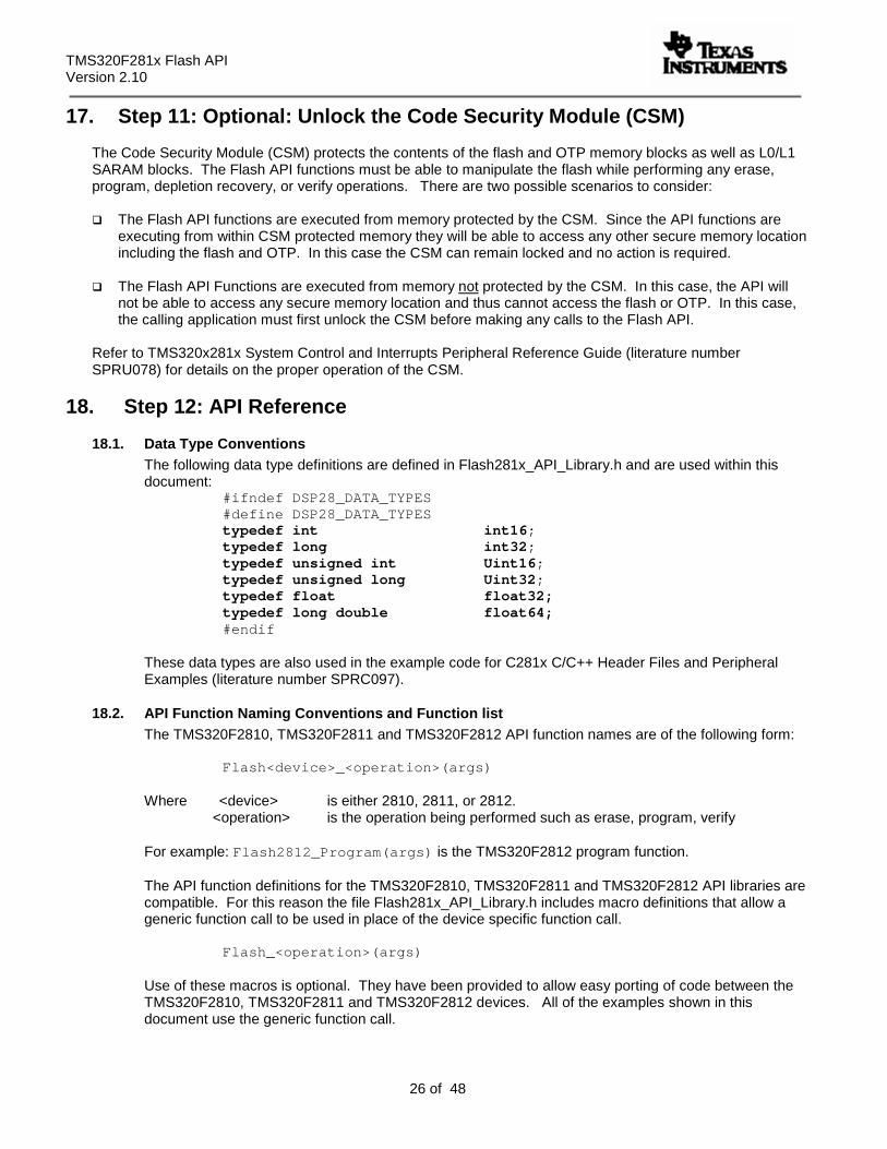
17. Step 11: Optional: Unlock the Code Security Module (CSM)
The Code Security Module (CSM) protects the contents of the flash and OTP memory blocks as well as L0/L1 SARAM blocks. The Flash API functions must be able to manipulate the flash while performing any erase, program, depletion recovery, or verify operations. There are two possible scenarios to consider:
The Flash API functions are executed from memory protected by the CSM. Since the API functions are executing from within CSM protected memory they will be able to access any other secure memory location including the flash and OTP. In this case the CSM can remain locked and no action is required.
The Flash API Functions are executed from memory not protected by the CSM. In this case, the API will
not be able to access any secure memory location and thus cannot access the flash or OTP. In this case, the calling application must first unlock the CSM before making any calls to the Flash API.
Refer to TMS320x281x System Control and Interrupts Peripheral Reference Guide (literature number SPRU078) for details on the proper operation of the CSM.
18. Step 12: API Reference
18.1. Data Type Conventions The following data type definitions are defined in Flash281x_API_Library.h and are used within this document:
#ifndef DSP28_DATA_TYPES #define DSP28_DATA_TYPES typedef int int16; typedef long int32; typedef unsigned int Uint16; typedef unsigned long Uint32; typedef float float32; typedef long double float64; #endif
These data types are also used in the example code for C281x C/C++ Header Files and Peripheral Examples (literature number SPRC097).
18.2. API Function Naming Conventions and Function list The TMS320F2810, TMS320F2811 and TMS320F2812 API function names are of the following form:
Flash<device>_<operation>(args) Where <device> is either 2810, 2811, or 2812. <operation> is the operation being performed such as erase, program, verify For example: Flash2812_Program(args) is the TMS320F2812 program function. The API function definitions for the TMS320F2810, TMS320F2811 and TMS320F2812 API libraries are compatible. For this reason the file Flash281x_API_Library.h includes macro definitions that allow a generic function call to be used in place of the device specific function call.
Flash_<operation>(args) Use of these macros is optional. They have been provided to allow easy porting of code between the TMS320F2810, TMS320F2811 and TMS320F2812 devices. All of the examples shown in this document use the generic function call.
TMS320F281x Flash API Version 2.00
27 of 48
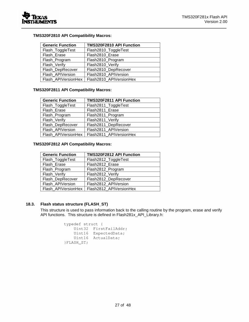
TMS320F2810 API Compatibility Macros:
TMS320F2811 API Compatibility Macros:
TMS320F2812 API Compatibility Macros:
18.3. Flash status structure (FLASH_ST) This structure is used to pass information back to the calling routine by the program, erase and verify API functions. This structure is defined in Flash281x_API_Library.h:
typedef struct { Uint32 FirstFailAddr; Uint16 ExpectedData; Uint16 ActualData; }FLASH_ST;
Generic Function TMS320F2810 API Function Flash_ToggleTest Flash2810_ToggleTest Flash_Erase Flash2810_Erase Flash_Program Flash2810_Program Flash_Verify Flash2810_Verify Flash_DepRecover Flash2810_DepRecover Flash_APIVersion Flash2810_APIVersion Flash_APIVersionHex Flash2810_APIVersionHex
Generic Function TMS320F2811 API Function Flash_ToggleTest Flash2811_ToggleTest Flash_Erase Flash2811_Erase Flash_Program Flash2811_Program Flash_Verify Flash2811_Verify Flash_DepRecover Flash2811_DepRecover Flash_APIVersion Flash2811_APIVersion Flash_APIVersionHex Flash2811_APIVersionHex
Generic Function TMS320F2812 API Function Flash_ToggleTest Flash2812_ToggleTest Flash_Erase Flash2812_Erase Flash_Program Flash2812_Program Flash_Verify Flash2812_Verify Flash_DepRecover Flash2812_DepRecover Flash_APIVersion Flash2812_APIVersion Flash_APIVersionHex Flash2812_APIVersionHex
TMS320F281x Flash API Version 2.10
28 of 48
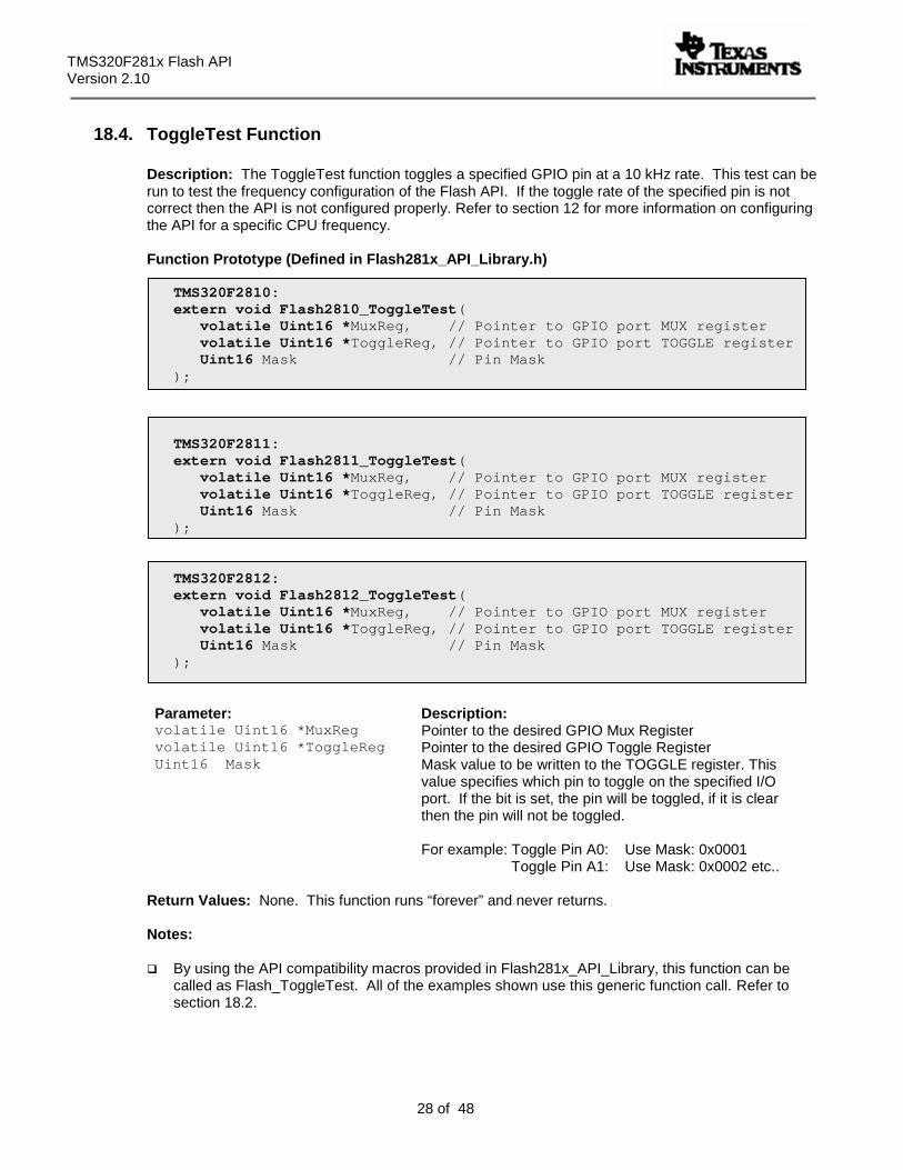
18.4. ToggleTest Function
Description: The ToggleTest function toggles a specified GPIO pin at a 10 kHz rate. This test can be run to test the frequency configuration of the Flash API. If the toggle rate of the specified pin is not correct then the API is not configured properly. Refer to section 12 for more information on configuring the API for a specific CPU frequency.
Function Prototype (Defined in Flash281x_API_Library.h)
TMS320F2810: extern void Flash2810_ToggleTest( volatile Uint16 *MuxReg, // Pointer to GPIO port MUX register volatile Uint16 *ToggleReg, // Pointer to GPIO port TOGGLE register Uint16 Mask // Pin Mask );
TMS320F2811: extern void Flash2811_ToggleTest( volatile Uint16 *MuxReg, // Pointer to GPIO port MUX register volatile Uint16 *ToggleReg, // Pointer to GPIO port TOGGLE register Uint16 Mask // Pin Mask );
TMS320F2812: extern void Flash2812_ToggleTest( volatile Uint16 *MuxReg, // Pointer to GPIO port MUX register volatile Uint16 *ToggleReg, // Pointer to GPIO port TOGGLE register Uint16 Mask // Pin Mask );
Parameter: Description: volatile Uint16 *MuxReg Pointer to the desired GPIO Mux Register volatile Uint16 *ToggleReg Pointer to the desired GPIO Toggle Register Uint16 Mask Mask value to be written to the TOGGLE register. This
value specifies which pin to toggle on the specified I/O port. If the bit is set, the pin will be toggled, if it is clear then the pin will not be toggled. For example: Toggle Pin A0: Use Mask: 0x0001 Toggle Pin A1: Use Mask: 0x0002 etc..
Return Values: None. This function runs “forever” and never returns. Notes:
By using the API compatibility macros provided in Flash281x_API_Library, this function can be called as Flash_ToggleTest. All of the examples shown use this generic function call. Refer to section 18.2.
TMS320F281x Flash API Version 2.00
29 of 48
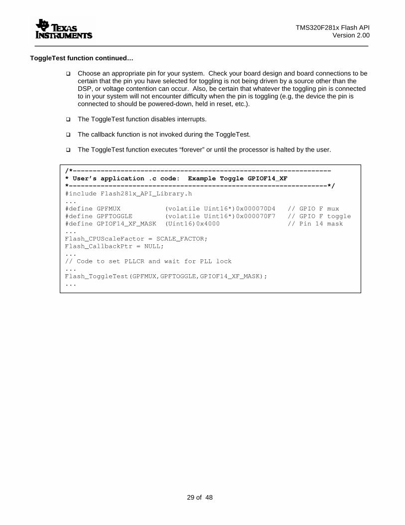
ToggleTest function continued…
Choose an appropriate pin for your system. Check your board design and board connections to be certain that the pin you have selected for toggling is not being driven by a source other than the DSP, or voltage contention can occur. Also, be certain that whatever the toggling pin is connected to in your system will not encounter difficulty when the pin is toggling (e.g, the device the pin is connected to should be powered-down, held in reset, etc.).
The ToggleTest function disables interrupts.
The callback function is not invoked during the ToggleTest.
The ToggleTest function executes “forever” or until the processor is halted by the user.
/*----------------------------------------------------------------- * User’s application .c code: Example Toggle GPIOF14_XF *-----------------------------------------------------------------*/ #include Flash281x_API_Library.h ... #define GPFMUX (volatile Uint16*)0x000070D4 // GPIO F mux #define GPFTOGGLE (volatile Uint16*)0x000070F7 // GPIO F toggle #define GPIOF14_XF_MASK (Uint16)0x4000 // Pin 14 mask ... Flash_CPUScaleFactor = SCALE_FACTOR; Flash_CallbackPtr = NULL; ... // Code to set PLLCR and wait for PLL lock ... Flash_ToggleTest(GPFMUX,GPFTOGGLE,GPIOF14_XF_MASK); ...
TMS320F281x Flash API Version 2.10
30 of 48
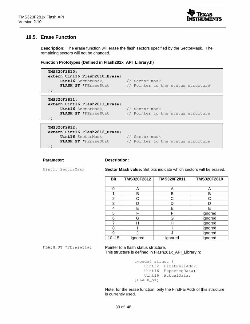
18.5. Erase Function
Description: The erase function will erase the flash sectors specified by the SectorMask. The remaining sectors will not be changed. Function Prototypes (Defined in Flash281x_API_Library.h)
TMS320F2810: extern Uint16 Flash2810_Erase( Uint16 SectorMask, // Sector mask FLASH_ST *FEraseStat // Pointer to the status structure );
TMS320F2811:
extern Uint16 Flash2811_Erase( Uint16 SectorMask, // Sector mask FLASH_ST *FEraseStat // Pointer to the status structure );
TMS320F2812:
extern Uint16 Flash2812_Erase( Uint16 SectorMask, // Sector mask FLASH_ST *FEraseStat // Pointer to the status structure );
Parameter: Description: Uint16 SectorMask
Sector Mask value: Set bits indicate which sectors will be erased.
Bit TMS320F2812
TMS320F2811
TMS320F2810
0 A A A 1 B B B 2 C C C 3 D D D 4 E E E 5 F F ignored 6 G G ignored 7 H H ignored 8 I I ignored 9 J J ignored
10 -15 ignored ignored ignored FLASH_ST *FEraseStat
Pointer to a flash status structure. This structure is defined in Flash281x_API_Library.h:
typedef struct { Uint32 FirstFailAddr; Uint16 ExpectedData; Uint16 ActualData; }FLASH_ST;
Note: for the erase function, only the FirstFailAddr of this structure is currently used.
TMS320F281x Flash API Version 2.00
31 of 48
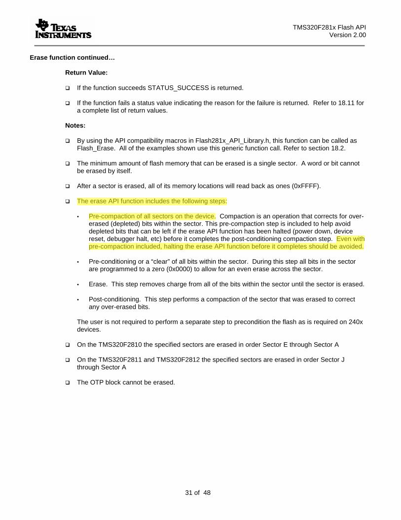
Erase function continued… Return Value:
If the function succeeds STATUS_SUCCESS is returned.
If the function fails a status value indicating the reason for the failure is returned. Refer to 18.11 for a complete list of return values.
Notes:
By using the API compatibility macros in Flash281x_API_Library.h, this function can be called as Flash_Erase. All of the examples shown use this generic function call. Refer to section 18.2.
The minimum amount of flash memory that can be erased is a single sector. A word or bit cannot
be erased by itself.
After a sector is erased, all of its memory locations will read back as ones (0xFFFF).
The erase API function includes the following steps:
• Pre-compaction of all sectors on the device. Compaction is an operation that corrects for over-erased (depleted) bits within the sector. This pre-compaction step is included to help avoid depleted bits that can be left if the erase API function has been halted (power down, device reset, debugger halt, etc) before it completes the post-conditioning compaction step. Even with pre-compaction included, halting the erase API function before it completes should be avoided.
• Pre-conditioning or a “clear” of all bits within the sector. During this step all bits in the sector
are programmed to a zero (0x0000) to allow for an even erase across the sector. • Erase. This step removes charge from all of the bits within the sector until the sector is erased.
• Post-conditioning. This step performs a compaction of the sector that was erased to correct
any over-erased bits. The user is not required to perform a separate step to precondition the flash as is required on 240x devices.
On the TMS320F2810 the specified sectors are erased in order Sector E through Sector A
On the TMS320F2811 and TMS320F2812 the specified sectors are erased in order Sector J
through Sector A
The OTP block cannot be erased.
TMS320F281x Flash API Version 2.10
32 of 48
Erase function continued…
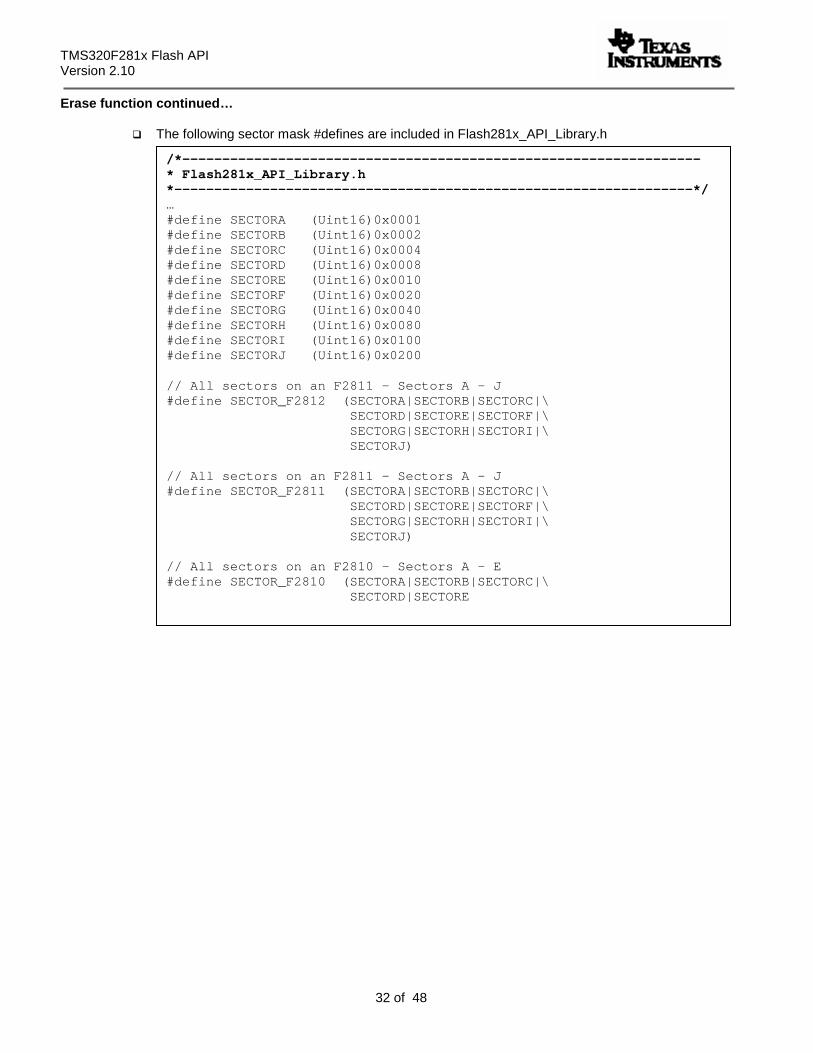
The following sector mask #defines are included in Flash281x_API_Library.h
/*----------------------------------------------------------------- * Flash281x_API_Library.h *-----------------------------------------------------------------*/ … #define SECTORA (Uint16)0x0001 #define SECTORB (Uint16)0x0002 #define SECTORC (Uint16)0x0004 #define SECTORD (Uint16)0x0008 #define SECTORE (Uint16)0x0010 #define SECTORF (Uint16)0x0020 #define SECTORG (Uint16)0x0040 #define SECTORH (Uint16)0x0080 #define SECTORI (Uint16)0x0100 #define SECTORJ (Uint16)0x0200 // All sectors on an F2811 - Sectors A - J #define SECTOR_F2812 (SECTORA|SECTORB|SECTORC|\
SECTORD|SECTORE|SECTORF|\ SECTORG|SECTORH|SECTORI|\ SECTORJ)
// All sectors on an F2811 - Sectors A - J #define SECTOR_F2811 (SECTORA|SECTORB|SECTORC|\
SECTORD|SECTORE|SECTORF|\ SECTORG|SECTORH|SECTORI|\ SECTORJ)
// All sectors on an F2810 - Sectors A - E #define SECTOR_F2810 (SECTORA|SECTORB|SECTORC|\
SECTORD|SECTORE
TMS320F281x Flash API Version 2.00
33 of 48
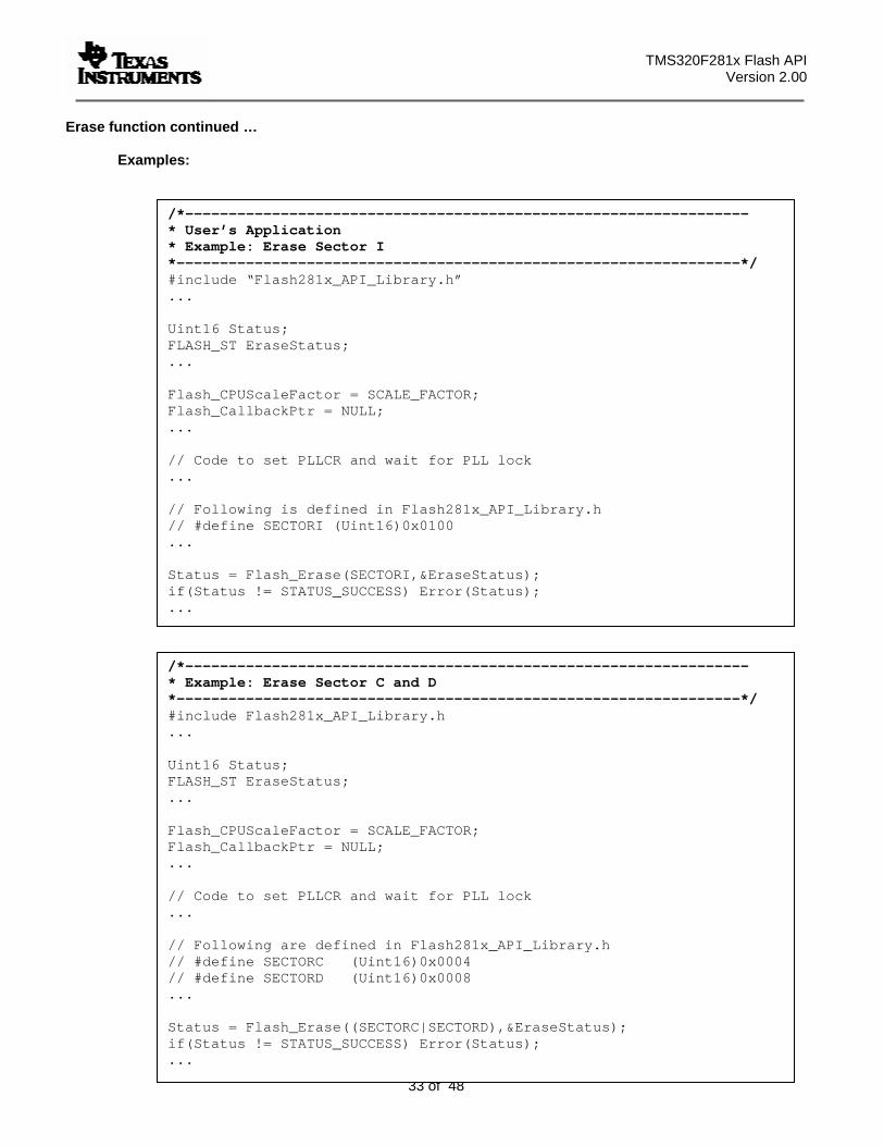
Erase function continued … Examples:
/*----------------------------------------------------------------- * User’s Application * Example: Erase Sector I *-----------------------------------------------------------------*/ #include “Flash281x_API_Library.h” ... Uint16 Status; FLASH_ST EraseStatus; ... Flash_CPUScaleFactor = SCALE_FACTOR; Flash_CallbackPtr = NULL; ... // Code to set PLLCR and wait for PLL lock ... // Following is defined in Flash281x_API_Library.h // #define SECTORI (Uint16)0x0100 ... Status = Flash_Erase(SECTORI,&EraseStatus); if(Status != STATUS_SUCCESS) Error(Status); ...
/*----------------------------------------------------------------- * Example: Erase Sector C and D *-----------------------------------------------------------------*/ #include Flash281x_API_Library.h ... Uint16 Status; FLASH_ST EraseStatus; ... Flash_CPUScaleFactor = SCALE_FACTOR; Flash_CallbackPtr = NULL; ... // Code to set PLLCR and wait for PLL lock ... // Following are defined in Flash281x_API_Library.h // #define SECTORC (Uint16)0x0004 // #define SECTORD (Uint16)0x0008 ... Status = Flash_Erase((SECTORC|SECTORD),&EraseStatus); if(Status != STATUS_SUCCESS) Error(Status); ...
TMS320F281x Flash API Version 2.10
34 of 48
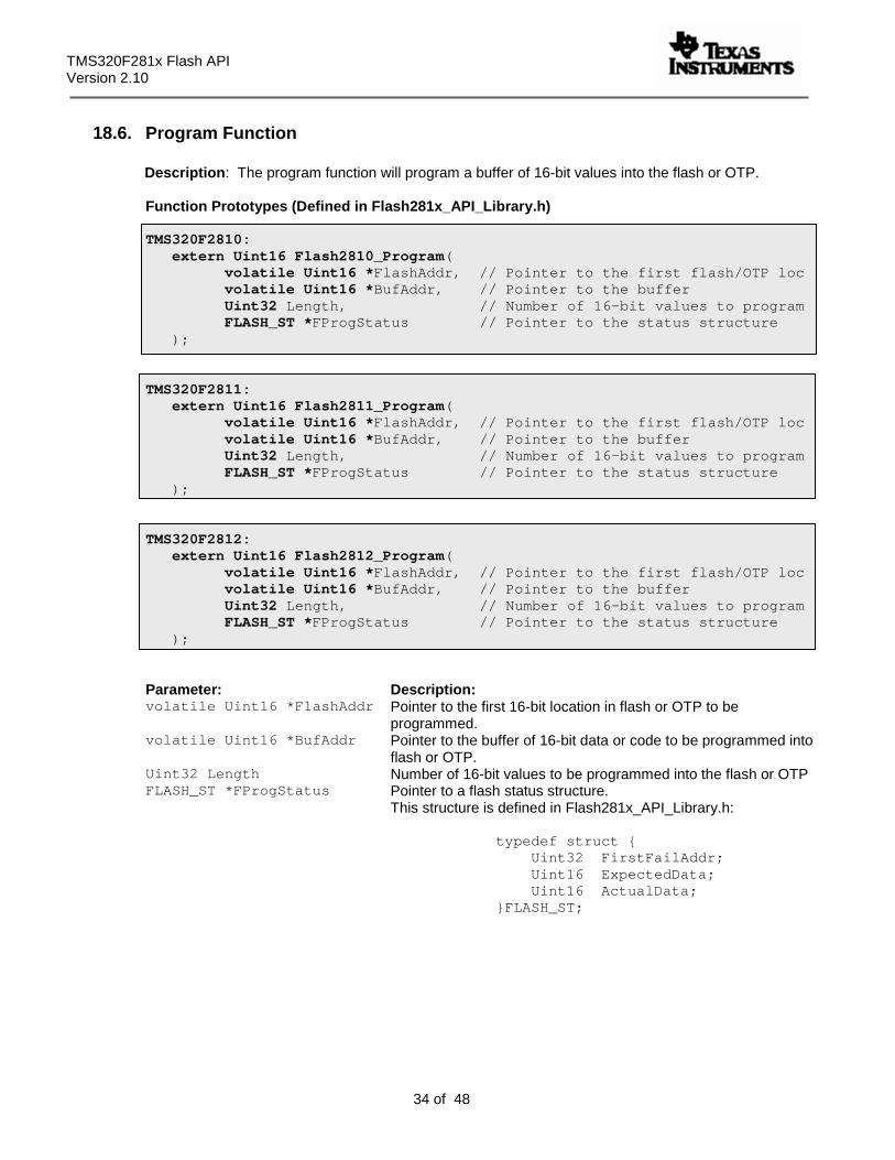
18.6. Program Function
Description: The program function will program a buffer of 16-bit values into the flash or OTP.
Function Prototypes (Defined in Flash281x_API_Library.h)
TMS320F2810: extern Uint16 Flash2810_Program( volatile Uint16 *FlashAddr, // Pointer to the first flash/OTP loc volatile Uint16 *BufAddr, // Pointer to the buffer Uint32 Length, // Number of 16-bit values to program FLASH_ST *FProgStatus // Pointer to the status structure );
TMS320F2811:
extern Uint16 Flash2811_Program( volatile Uint16 *FlashAddr, // Pointer to the first flash/OTP loc volatile Uint16 *BufAddr, // Pointer to the buffer Uint32 Length, // Number of 16-bit values to program FLASH_ST *FProgStatus // Pointer to the status structure );
TMS320F2812:
extern Uint16 Flash2812_Program( volatile Uint16 *FlashAddr, // Pointer to the first flash/OTP loc volatile Uint16 *BufAddr, // Pointer to the buffer Uint32 Length, // Number of 16-bit values to program FLASH_ST *FProgStatus // Pointer to the status structure );
Parameter: Description: volatile Uint16 *FlashAddr Pointer to the first 16-bit location in flash or OTP to be
programmed. volatile Uint16 *BufAddr Pointer to the buffer of 16-bit data or code to be programmed into
flash or OTP. Uint32 Length Number of 16-bit values to be programmed into the flash or OTP FLASH_ST *FProgStatus Pointer to a flash status structure.
This structure is defined in Flash281x_API_Library.h:
typedef struct { Uint32 FirstFailAddr; Uint16 ExpectedData; Uint16 ActualData; }FLASH_ST;
TMS320F281x Flash API Version 2.00
35 of 48
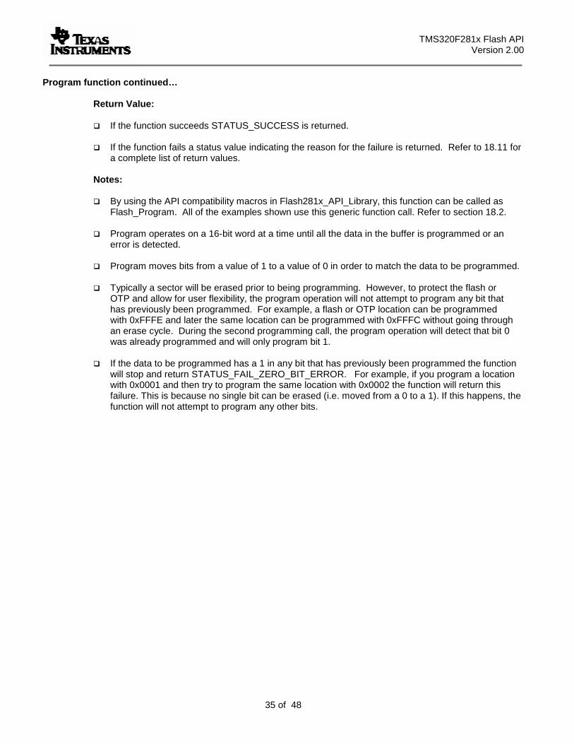
Program function continued… Return Value:
If the function succeeds STATUS_SUCCESS is returned.
If the function fails a status value indicating the reason for the failure is returned. Refer to 18.11 for a complete list of return values.
Notes:
By using the API compatibility macros in Flash281x_API_Library, this function can be called as Flash_Program. All of the examples shown use this generic function call. Refer to section 18.2.
Program operates on a 16-bit word at a time until all the data in the buffer is programmed or an
error is detected.
Program moves bits from a value of 1 to a value of 0 in order to match the data to be programmed.
Typically a sector will be erased prior to being programming. However, to protect the flash or OTP and allow for user flexibility, the program operation will not attempt to program any bit that has previously been programmed. For example, a flash or OTP location can be programmed with 0xFFFE and later the same location can be programmed with 0xFFFC without going through an erase cycle. During the second programming call, the program operation will detect that bit 0 was already programmed and will only program bit 1.
If the data to be programmed has a 1 in any bit that has previously been programmed the function
will stop and return STATUS_FAIL_ZERO_BIT_ERROR. For example, if you program a location with 0x0001 and then try to program the same location with 0x0002 the function will return this failure. This is because no single bit can be erased (i.e. moved from a 0 to a 1). If this happens, the function will not attempt to program any other bits.
TMS320F281x Flash API Version 2.10
36 of 48
Program function continued…
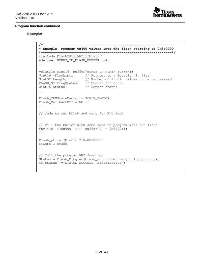
Example:
/*----------------------------------------------------------------- * Example: Program 0x400 values into the flash starting at 0x3F0000 *-----------------------------------------------------------------*/ #include Flash281x_API_Library.h #define WORDS_IN_FLASH_BUFFER 0x400 ... volatile Uint16 Buffer[WORDS_IN_FLASH_BUFFER]; Uint16 *Flash_ptr; // Pointer to a location in flash Uint32 Length; // Number of 16-bit values to be programmed FLASH_ST ProgStatus; // Status structure Uint16 Status; // Return status ... Flash_CPUScaleFactor = SCALE_FACTOR; Flash_CallbackPtr = NULL; ... // Code to set PLLCR and wait for PLL lock ... // Fill the buffer with some data to program into the flash for(i=0; i<0x400; i++) Buffer[i] = 0x8000+i; ... Flash_ptr = (Uint16 *)0x003F0000; Length = 0x400; ... // Call the program API function Status = Flash_Program(Flash_ptr,Buffer,Length,&ProgStatus); if(Status != STATUS_SUCCESS) Error(Status);
TMS320F281x Flash API Version 2.00
37 of 48
18.7. Verify Function
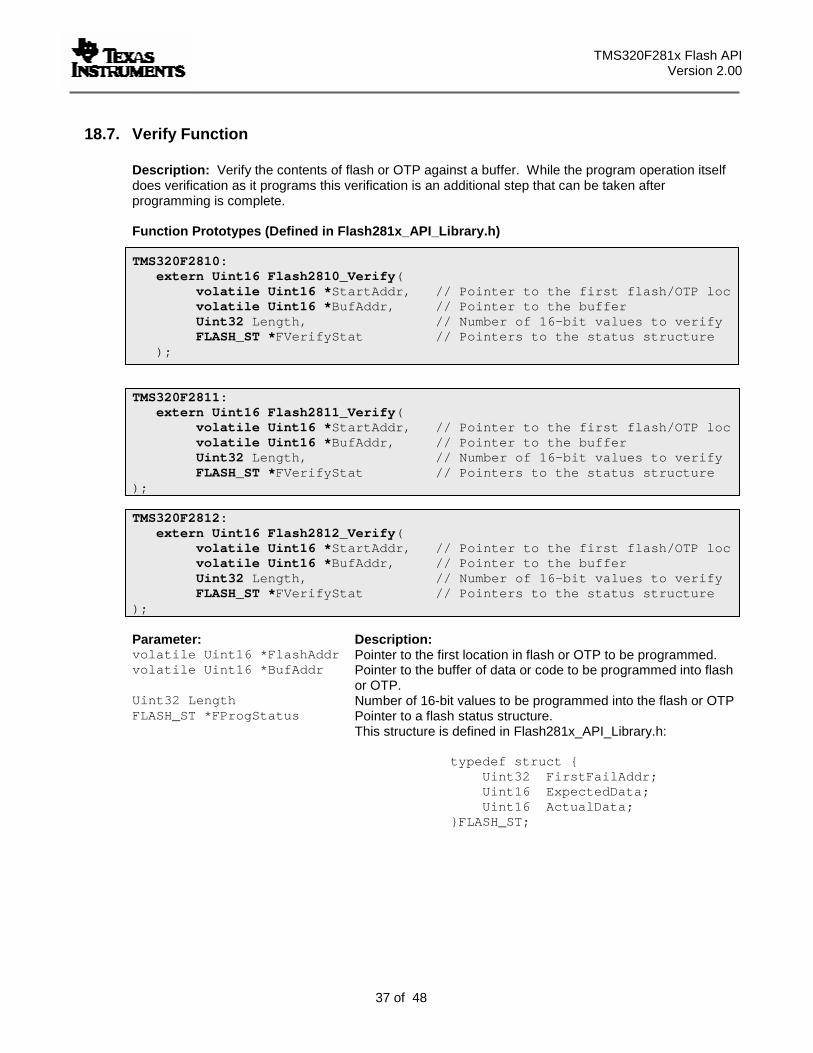
Description: Verify the contents of flash or OTP against a buffer. While the program operation itself does verification as it programs this verification is an additional step that can be taken after programming is complete. Function Prototypes (Defined in Flash281x_API_Library.h) TMS320F2810:
extern Uint16 Flash2810_Verify( volatile Uint16 *StartAddr, // Pointer to the first flash/OTP loc volatile Uint16 *BufAddr, // Pointer to the buffer Uint32 Length, // Number of 16-bit values to verify FLASH_ST *FVerifyStat // Pointers to the status structure );
TMS320F2811:
extern Uint16 Flash2811_Verify( volatile Uint16 *StartAddr, // Pointer to the first flash/OTP loc volatile Uint16 *BufAddr, // Pointer to the buffer Uint32 Length, // Number of 16-bit values to verify FLASH_ST *FVerifyStat // Pointers to the status structure
); TMS320F2812:
extern Uint16 Flash2812_Verify( volatile Uint16 *StartAddr, // Pointer to the first flash/OTP loc volatile Uint16 *BufAddr, // Pointer to the buffer Uint32 Length, // Number of 16-bit values to verify FLASH_ST *FVerifyStat // Pointers to the status structure
); Parameter: Description: volatile Uint16 *FlashAddr Pointer to the first location in flash or OTP to be programmed. volatile Uint16 *BufAddr Pointer to the buffer of data or code to be programmed into flash
or OTP. Uint32 Length Number of 16-bit values to be programmed into the flash or OTP FLASH_ST *FProgStatus Pointer to a flash status structure.
This structure is defined in Flash281x_API_Library.h:
typedef struct { Uint32 FirstFailAddr; Uint16 ExpectedData; Uint16 ActualData; }FLASH_ST;
TMS320F281x Flash API Version 2.10
38 of 48
Verify function continued…
Return Value:
If the function succeeds STATUS_SUCCESS is returned.
If the function fails a status value indicating the reason for the failure is returned. Refer to 18.11 for a complete list of return values.
Notes:
By using the API compatibility macros provided in Flash281x_API_Library, this function can be called as Flash_Verify. All of the examples shown use this generic function call. Refer to section 18.2.
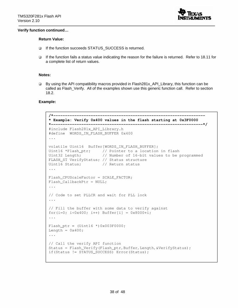
Example:
/*----------------------------------------------------------------- * Example: Verify 0x400 values in the flash starting at 0x3F0000 *-----------------------------------------------------------------*/ #include Flash281x_API_Library.h #define WORDS_IN_FLASH_BUFFER 0x400 ... volatile Uint16 Buffer[WORDS_IN_FLASH_BUFFER]; Uint16 *Flash_ptr; // Pointer to a location in flash Uint32 Length; // Number of 16-bit values to be programmed FLASH_ST VerifyStatus; // Status structure Uint16 Status; // Return status ... Flash_CPUScaleFactor = SCALE_FACTOR; Flash_CallbackPtr = NULL; ... // Code to set PLLCR and wait for PLL lock ... // Fill the buffer with some data to verify against for(i=0; i<0x400; i++) Buffer[i] = 0x8000+i; ... Flash_ptr = (Uint16 *)0x003F0000; Length = 0x400; ... // Call the verify API function Status = Flash_Verify(Flash_ptr,Buffer,Length,&VerifyStatus); if(Status != STATUS_SUCCESS) Error(Status);
TMS320F281x Flash API Version 2.00
39 of 48
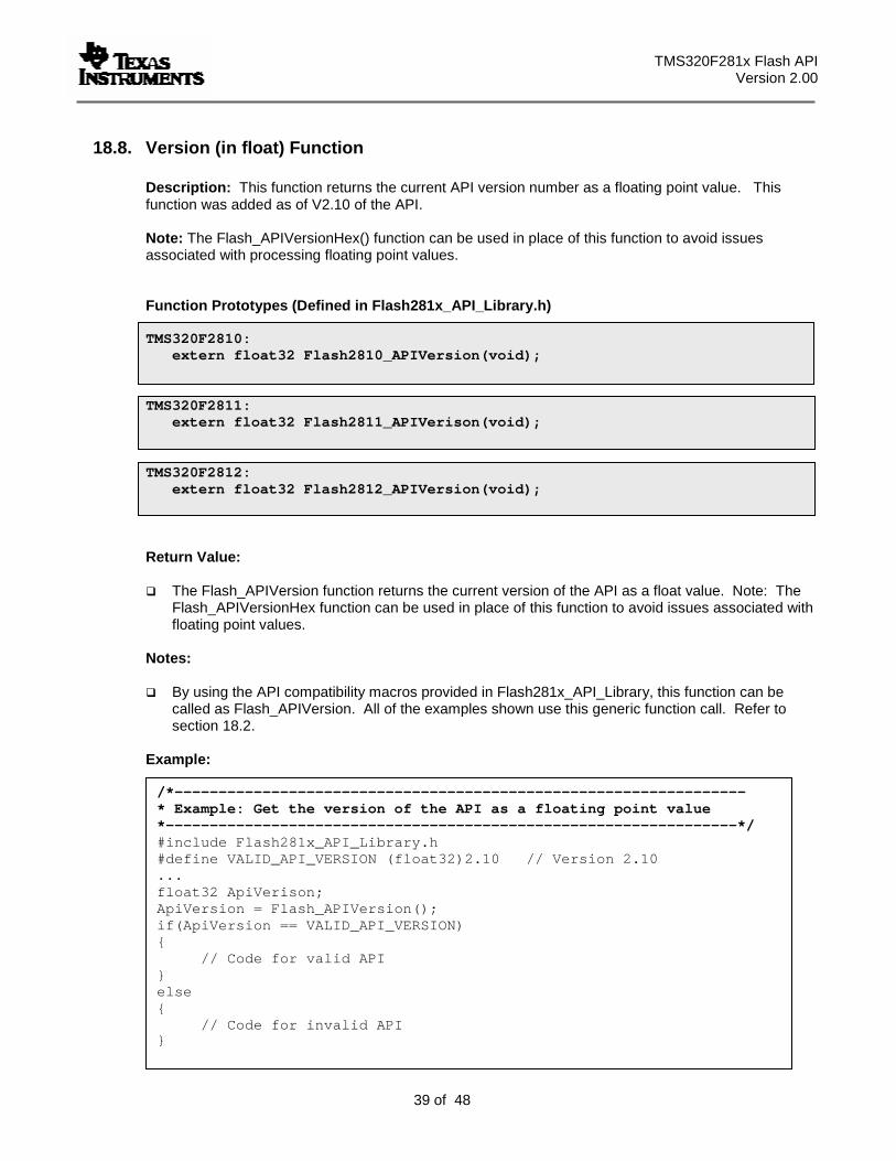
18.8. Version (in float) Function
Description: This function returns the current API version number as a floating point value. This function was added as of V2.10 of the API. Note: The Flash_APIVersionHex() function can be used in place of this function to avoid issues associated with processing floating point values.
Function Prototypes (Defined in Flash281x_API_Library.h) TMS320F2810:
extern float32 Flash2810_APIVersion(void); TMS320F2811:
extern float32 Flash2811_APIVerison(void); TMS320F2812:
extern float32 Flash2812_APIVersion(void);
Return Value:
The Flash_APIVersion function returns the current version of the API as a float value. Note: The Flash_APIVersionHex function can be used in place of this function to avoid issues associated with floating point values.
Notes:
By using the API compatibility macros provided in Flash281x_API_Library, this function can be called as Flash_APIVersion. All of the examples shown use this generic function call. Refer to section 18.2.
Example:
/*----------------------------------------------------------------- * Example: Get the version of the API as a floating point value *-----------------------------------------------------------------*/ #include Flash281x_API_Library.h #define VALID_API_VERSION (float32)2.10 // Version 2.10 ... float32 ApiVerison; ApiVersion = Flash_APIVersion(); if(ApiVersion == VALID_API_VERSION) { // Code for valid API } else { // Code for invalid API }
TMS320F281x Flash API Version 2.10
40 of 48
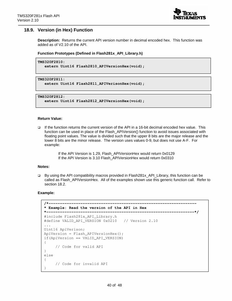
18.9. Version (in Hex) Function
Description: Returns the current API version number in decimal encoded hex. This function was added as of V2.10 of the API. Function Prototypes (Defined in Flash281x_API_Library.h) TMS320F2810:
extern Uint16 Flash2810_APIVersionHex(void); TMS320F2811:
extern Uint16 Flash2811_APIVerisonHex(void); TMS320F2812:
extern Uint16 Flash2812_APIVersionHex(void);
Return Value:
If the function returns the current version of the API in a 16-bit decimal encoded hex value. This function can be used in place of the Flash_APIVersion() function to avoid issues associated with floating point values. The value is divided such that the upper 8 bits are the major release and the lower 8 bits are the minor release. The version uses values 0-9, but does not use A-F. For example: If the API Version is 1.29, Flash_APIVersionHex would return 0x0129 If the API Version is 3.10 Flash_APIVersionHex would return 0x0310
Notes:
By using the API compatibility macros provided in Flash281x_API_Library, this function can be called as Flash_APIVersionHex. All of the examples shown use this generic function call. Refer to section 18.2.
Example: /*-----------------------------------------------------------------
* Example: Read the version of the API in Hex *-----------------------------------------------------------------*/ #include Flash281x_API_Library.h #define VALID_API_VERSION 0x0210 // Version 2.10 ... Uint16 ApiVerison; ApiVersion = Flash_APIVersionHex(); if(ApiVersion == VALID_API_VERSION) { // Code for valid API } else { // Code for invalid API }
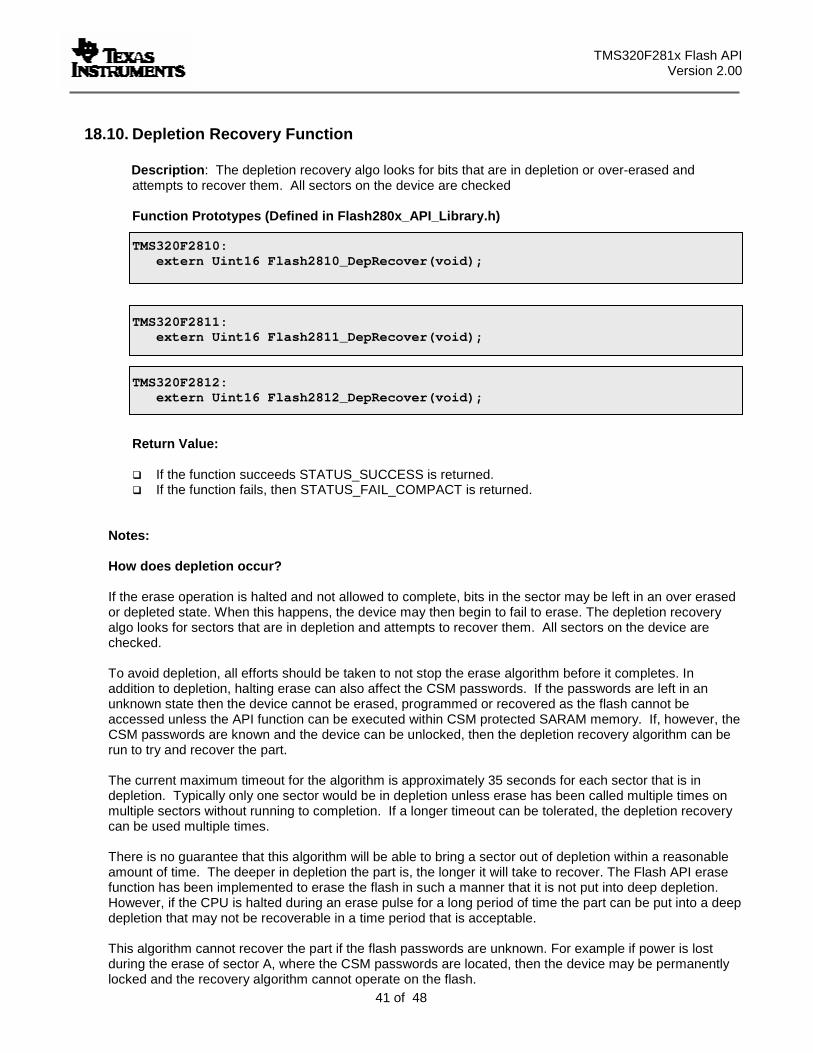
TMS320F281x Flash API Version 2.00
41 of 48
18.10. Depletion Recovery Function
Description: The depletion recovery algo looks for bits that are in depletion or over-erased and attempts to recover them. All sectors on the device are checked
Function Prototypes (Defined in Flash280x_API_Library.h)
TMS320F2810:
extern Uint16 Flash2810_DepRecover(void);
TMS320F2811:
extern Uint16 Flash2811_DepRecover(void); TMS320F2812:
extern Uint16 Flash2812_DepRecover(void);
Return Value:
If the function succeeds STATUS_SUCCESS is returned. If the function fails, then STATUS_FAIL_COMPACT is returned.
Notes:
How does depletion occur?
If the erase operation is halted and not allowed to complete, bits in the sector may be left in an over erased or depleted state. When this happens, the device may then begin to fail to erase. The depletion recovery algo looks for sectors that are in depletion and attempts to recover them. All sectors on the device are checked. To avoid depletion, all efforts should be taken to not stop the erase algorithm before it completes. In addition to depletion, halting erase can also affect the CSM passwords. If the passwords are left in an unknown state then the device cannot be erased, programmed or recovered as the flash cannot be accessed unless the API function can be executed within CSM protected SARAM memory. If, however, the CSM passwords are known and the device can be unlocked, then the depletion recovery algorithm can be run to try and recover the part. The current maximum timeout for the algorithm is approximately 35 seconds for each sector that is in depletion. Typically only one sector would be in depletion unless erase has been called multiple times on multiple sectors without running to completion. If a longer timeout can be tolerated, the depletion recovery can be used multiple times. There is no guarantee that this algorithm will be able to bring a sector out of depletion within a reasonable amount of time. The deeper in depletion the part is, the longer it will take to recover. The Flash API erase function has been implemented to erase the flash in such a manner that it is not put into deep depletion. However, if the CPU is halted during an erase pulse for a long period of time the part can be put into a deep depletion that may not be recoverable in a time period that is acceptable. This algorithm cannot recover the part if the flash passwords are unknown. For example if power is lost during the erase of sector A, where the CSM passwords are located, then the device may be permanently locked and the recovery algorithm cannot operate on the flash.
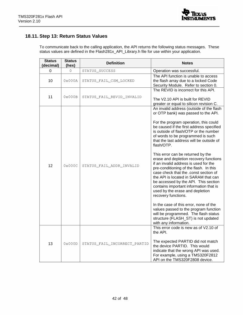
TMS320F281x Flash API Version 2.10
42 of 48
18.11. Step 13: Return Status Values
To communicate back to the calling application, the API returns the following status messages. These status values are defined in the Flash281x_API_Library.h file for use within your application.
Status
(decimal) Status (hex) Definition Notes
0 0 STATUS_SUCCESS Operation was successful.
10 0x000A STATUS_FAIL_CSM_LOCKED The API function is unable to access the flash array due to a locked Code Security Module. Refer to section 0.
11 0x000B STATUS_FAIL_REVID_INVALID
The REVID is incorrect for this API. The V2.10 API is built for REVID greater or equal to silicon revision C.
12 0x000C STATUS_FAIL_ADDR_INVALID
An invalid address (outside of the flash or OTP bank) was passed to the API. For the program operation, this could be caused if the first address specified is outside of flash/OTP or the number of words to be programmed is such that the last address will be outside of flash/OTP. This error can be returned by the erase and depletion recovery functions if an invalid address is used for the pre-conditioning of the flash. In this case check that the .const section of the API is located in SARAM that can be accessed by the API. This section contains important information that is used by the erase and depletion recovery functions. In the case of this error, none of the values passed to the program function will be programmed. The flash status structure (FLASH_ST) is not updated with any information.
13 0x000D STATUS_FAIL_INCORRECT_PARTID
This error code is new as of V2.10 of the API. The expected PARTID did not match the device PARTID. This would indicate that the wrong API was used. For example, using a TMS320F2812 API on the TMS320F2808 device.
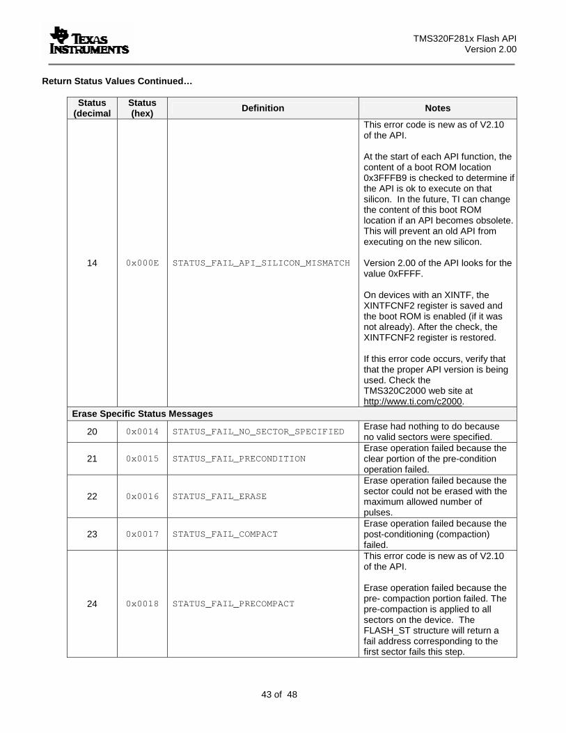
TMS320F281x Flash API Version 2.00
43 of 48
Return Status Values Continued…
Status (decimal
Status (hex) Definition Notes
14 0x000E STATUS_FAIL_API_SILICON_MISMATCH
This error code is new as of V2.10 of the API. At the start of each API function, the content of a boot ROM location 0x3FFFB9 is checked to determine if the API is ok to execute on that silicon. In the future, TI can change the content of this boot ROM location if an API becomes obsolete. This will prevent an old API from executing on the new silicon. Version 2.00 of the API looks for the value 0xFFFF. On devices with an XINTF, the XINTFCNF2 register is saved and the boot ROM is enabled (if it was not already). After the check, the XINTFCNF2 register is restored. If this error code occurs, verify that that the proper API version is being used. Check the TMS320C2000 web site at http://www.ti.com/c2000.
Erase Specific Status Messages
20 0x0014 STATUS_FAIL_NO_SECTOR_SPECIFIED Erase had nothing to do because no valid sectors were specified.
21 0x0015 STATUS_FAIL_PRECONDITION Erase operation failed because the clear portion of the pre-condition operation failed.
22 0x0016 STATUS_FAIL_ERASE
Erase operation failed because the sector could not be erased with the maximum allowed number of pulses.
23 0x0017 STATUS_FAIL_COMPACT Erase operation failed because the post-conditioning (compaction) failed.
24 0x0018 STATUS_FAIL_PRECOMPACT
This error code is new as of V2.10 of the API. Erase operation failed because the pre- compaction portion failed. The pre-compaction is applied to all sectors on the device. The FLASH_ST structure will return a fail address corresponding to the first sector fails this step.
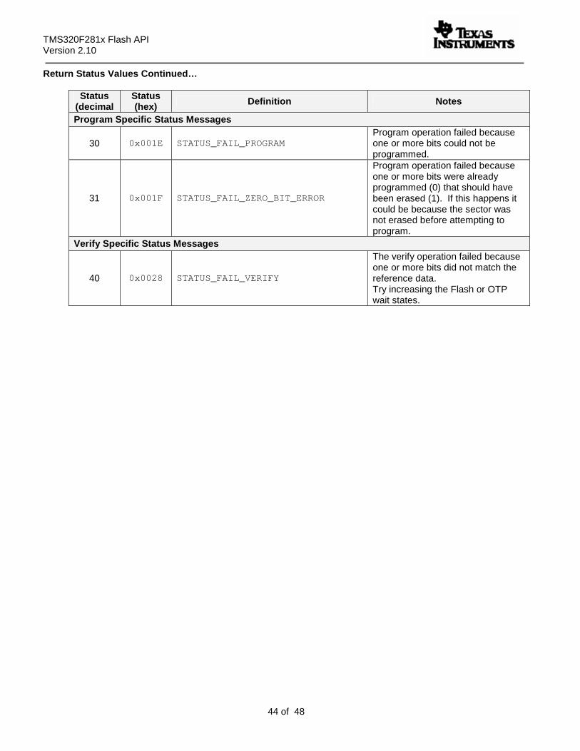
TMS320F281x Flash API Version 2.10
44 of 48
Return Status Values Continued…
Status (decimal
Status (hex) Definition Notes
Program Specific Status Messages
30 0x001E STATUS_FAIL_PROGRAM Program operation failed because one or more bits could not be programmed.
31 0x001F STATUS_FAIL_ZERO_BIT_ERROR
Program operation failed because one or more bits were already programmed (0) that should have been erased (1). If this happens it could be because the sector was not erased before attempting to program.
Verify Specific Status Messages
40 0x0028 STATUS_FAIL_VERIFY
The verify operation failed because one or more bits did not match the reference data. Try increasing the Flash or OTP wait states.
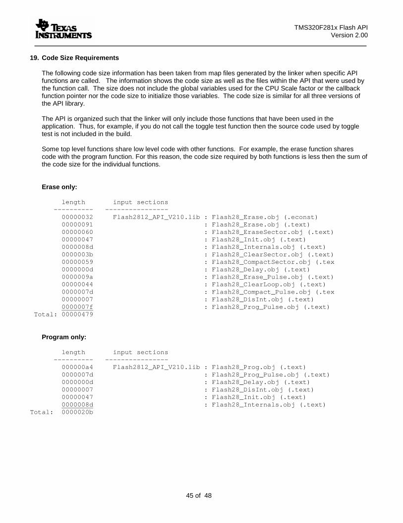
TMS320F281x Flash API Version 2.00
45 of 48
19. Code Size Requirements
The following code size information has been taken from map files generated by the linker when specific API functions are called. The information shows the code size as well as the files within the API that were used by the function call. The size does not include the global variables used for the CPU Scale factor or the callback function pointer nor the code size to initialize those variables. The code size is similar for all three versions of the API library. The API is organized such that the linker will only include those functions that have been used in the application. Thus, for example, if you do not call the toggle test function then the source code used by toggle test is not included in the build. Some top level functions share low level code with other functions. For example, the erase function shares code with the program function. For this reason, the code size required by both functions is less then the sum of the code size for the individual functions.
Erase only:
length input sections ---------- ---------------- 00000032 Flash2812_API_V210.lib : Flash28_Erase.obj (.econst) 00000091 : Flash28_Erase.obj (.text) 00000060 : Flash28_EraseSector.obj (.text) 00000047 : Flash28_Init.obj (.text) 0000008d : Flash28_Internals.obj (.text) 0000003b : Flash28_ClearSector.obj (.text) 00000059 : Flash28_CompactSector.obj (.tex 0000000d : Flash28_Delay.obj (.text) 0000009a : Flash28_Erase_Pulse.obj (.text) 00000044 : Flash28_ClearLoop.obj (.text) 0000007d : Flash28_Compact_Pulse.obj (.tex 00000007 : Flash28_DisInt.obj (.text) 0000007f : Flash28_Prog_Pulse.obj (.text)
Total: 00000479
Program only:
length input sections ---------- ---------------- 000000a4 Flash2812_API_V210.lib : Flash28_Prog.obj (.text) 0000007d : Flash28_Prog_Pulse.obj (.text) 0000000d : Flash28_Delay.obj (.text) 00000007 : Flash28_DisInt.obj (.text) 00000047 : Flash28_Init.obj (.text) 0000008d : Flash28_Internals.obj (.text)
Total: 0000020b
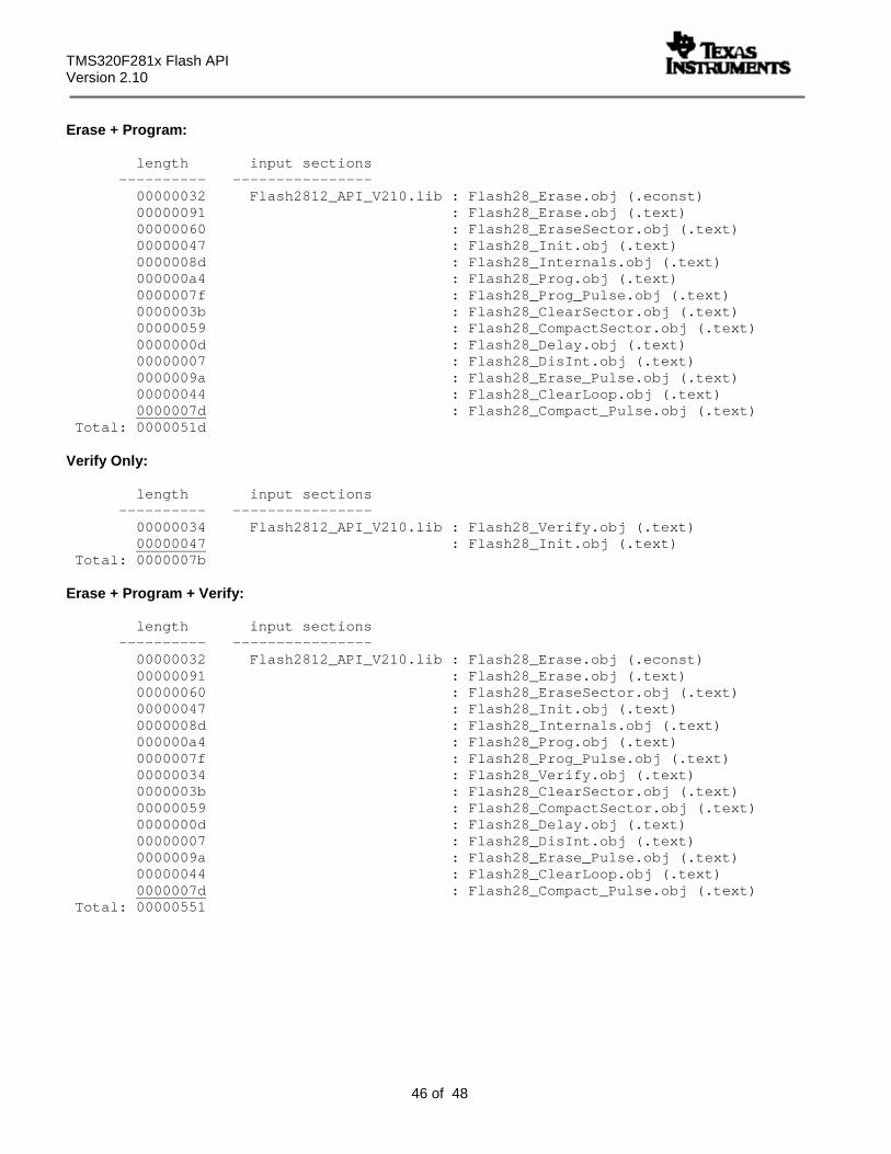
TMS320F281x Flash API Version 2.10
46 of 48
Erase + Program:
length input sections ---------- ---------------- 00000032 Flash2812_API_V210.lib : Flash28_Erase.obj (.econst) 00000091 : Flash28_Erase.obj (.text) 00000060 : Flash28_EraseSector.obj (.text) 00000047 : Flash28_Init.obj (.text) 0000008d : Flash28_Internals.obj (.text) 000000a4 : Flash28_Prog.obj (.text) 0000007f : Flash28_Prog_Pulse.obj (.text) 0000003b : Flash28_ClearSector.obj (.text) 00000059 : Flash28_CompactSector.obj (.text) 0000000d : Flash28_Delay.obj (.text) 00000007 : Flash28_DisInt.obj (.text) 0000009a : Flash28_Erase_Pulse.obj (.text) 00000044 : Flash28_ClearLoop.obj (.text) 0000007d : Flash28_Compact_Pulse.obj (.text)
Total: 0000051d Verify Only:
length input sections ---------- ---------------- 00000034 Flash2812_API_V210.lib : Flash28_Verify.obj (.text)
00000047 : Flash28_Init.obj (.text) Total: 0000007b
Erase + Program + Verify:
length input sections ---------- ---------------- 00000032 Flash2812_API_V210.lib : Flash28_Erase.obj (.econst) 00000091 : Flash28_Erase.obj (.text) 00000060 : Flash28_EraseSector.obj (.text) 00000047 : Flash28_Init.obj (.text) 0000008d : Flash28_Internals.obj (.text) 000000a4 : Flash28_Prog.obj (.text) 0000007f : Flash28_Prog_Pulse.obj (.text) 00000034 : Flash28_Verify.obj (.text) 0000003b : Flash28_ClearSector.obj (.text) 00000059 : Flash28_CompactSector.obj (.text) 0000000d : Flash28_Delay.obj (.text) 00000007 : Flash28_DisInt.obj (.text) 0000009a : Flash28_Erase_Pulse.obj (.text) 00000044 : Flash28_ClearLoop.obj (.text) 0000007d : Flash28_Compact_Pulse.obj (.text)
Total: 00000551
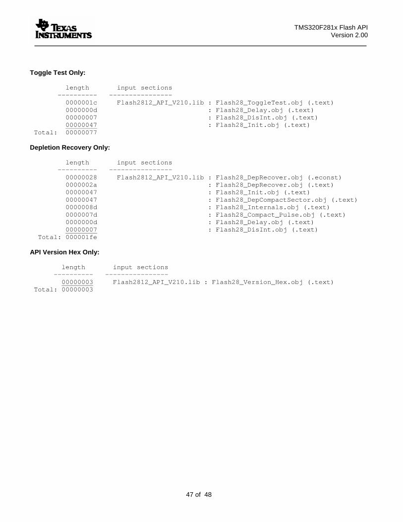
TMS320F281x Flash API Version 2.00
47 of 48
Toggle Test Only:
length input sections ---------- ---------------- 0000001c Flash2812_API_V210.lib : Flash28_ToggleTest.obj (.text) 0000000d : Flash28_Delay.obj (.text) 00000007 : Flash28_DisInt.obj (.text) 00000047 : Flash28_Init.obj (.text)
Total: 00000077
Depletion Recovery Only:
length input sections ---------- ---------------- 00000028 Flash2812_API_V210.lib : Flash28_DepRecover.obj (.econst) 0000002a : Flash28_DepRecover.obj (.text) 00000047 : Flash28_Init.obj (.text) 00000047 : Flash28_DepCompactSector.obj (.text) 0000008d : Flash28_Internals.obj (.text) 0000007d : Flash28_Compact_Pulse.obj (.text) 0000000d : Flash28_Delay.obj (.text) 00000007 : Flash28_DisInt.obj (.text)
Total: 000001fe API Version Hex Only:
length input sections ---------- ---------------- 00000003 Flash2812_API_V210.lib : Flash28_Version_Hex.obj (.text)
Total: 00000003
TMS320F281x Flash API Version 2.10
48 of 48
20. Files included in this release
The TMS320F2810, TMS320F2811 and TMS320F2812 each have an API library. Include the proper library for your device in your project. Since the API function call definitions are compatible between the F281x devices, the include files and documentation is the same for the TMS320F2810, TMS320F2811 and TMS320F2812. They have been duplicated under both sub-directories for convenience and clarity.
By default, <> = C:\tidcs\c28\Flash28_API\
TMS320F2810 API Library: <>\Flash2810_API_V210\lib\Flash2810_API_V210.lib API Include Files (also used for F2811 & F2812): <>\Flash2810_API_V210\include\Flash281x_API_Library.h <>\Flash2810_API_V210\include\Flash281x_API_Config.h Documentation: <>\Flash2810_API_V210\doc Example: <>\Flash2810_API_V210\example
TMS320F2811 API Library: <>\Flash2811_API_V210\lib\Flash2810_API_V210.lib API Include Files (also used for F2812): <>\Flash2811_API_V210\include\Flash281x_API_Library.h <>\Flash2811_API_V210\include\Flash281x_API_Config.h Documentation: <>\Flash2811_API_V210\doc Example: <>\Flash2811_API_V210\example
TMS320F2812 API Library: <>\Flash2812_API_V210\lib\Flash2812_API_V210.lib API Include Files (also used for F2810 & F2811): <>\Flash2812_API_V210\include\Flash281x_API_Library.h <>\Flash2812_API_V210\include\Flash281x_API_Config.h Documentation: <>\Flash2812_API_V210\doc Example: <>\Flash2812_API_V210\example