Embed Size (px)
Citation preview
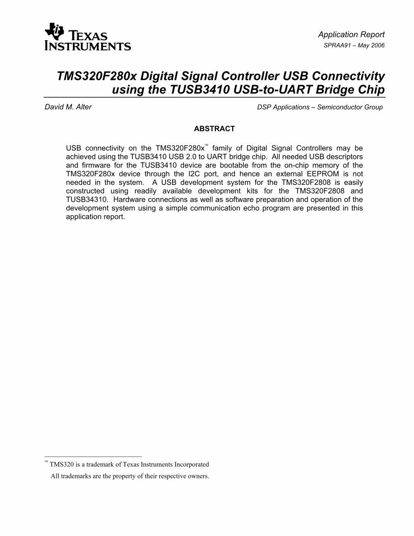
Application Report SPRAA91 – May 2006
TMS320F280x Digital Signal Controller USB Connectivity using the TUSB3410 USB-to-UART Bridge Chip
David M. Alter DSP Applications – Semiconductor Group
ABSTRACT
USB connectivity on the TMS320F280x family of Digital Signal Controllers may be achieved using the TUSB3410 USB 2.0 to UART bridge chip. All needed USB descriptors and firmware for the TUSB3410 device are bootable from the on-chip memory of the TMS320F280x device through the I2C port, and hence an external EEPROM is not needed in the system. A USB development system for the TMS320F2808 is easily constructed using readily available development kits for the TMS320F2808 and TUSB34310. Hardware connections as well as software preparation and operation of the development system using a simple communication echo program are presented in this application report.
TMS320 is a trademark of Texas Instruments Incorporated
All trademarks are the property of their respective owners.
SPRAA91
2 TMS320F280x Digital Signal Controller USB Connectivity using the TUSB3410 USB-to-UART Bridge Chip
Contents 1 Introduction .....................................................................................................................................3 2 USB Design Decisions with the TUSB3410 ..................................................................................4
2.1 VID and PID Values and Storage Location ...............................................................................4 2.2 Firmware Storage Location .......................................................................................................5 2.3 Host Driver ................................................................................................................................5 2.4 Device Serialization...................................................................................................................5
3 TMS320F280x to TUSB3410 Hardware Interface..........................................................................6 4 Development System Description .................................................................................................7 5 Software ...........................................................................................................................................9
5.1 TUSB3410 Software................................................................................................................10 5.2 TMS320F280x Software..........................................................................................................14 5.3 Host PC Software....................................................................................................................16
6 Running the Development System..............................................................................................16 6.1 Running the RAM Example .....................................................................................................16 6.2 Running the Flash Example ....................................................................................................20 6.3 Baud Rate Selection Information.............................................................................................21
7 Conclusion.....................................................................................................................................22 References.............................................................................................................................................23
Figures Figure 1. TUSB3410 In-System Usage..............................................................................................3 Figure 2. TMS320F280x to TUSB3410 Hardware Interface .............................................................7 Figure 3. Development System Connections ..................................................................................8 Figure 4. Development System Photograph....................................................................................9 Figure 5. Files for Header Generator Utility for VCP Applications ..............................................10 Figure 6. Byte2Word Utility Usage..................................................................................................12 Figure 7. Byte-packed ASCII Data File for TUSB3410...................................................................13 Figure 8. Including the TUSB3410 Data into the TMS320F280x Code.........................................13 Figure 9. Baud Rate Selection In HyperTerminal ..........................................................................21
Tables Table 1. Directory Structure of TMS320F2808 Example Code....................................................14 Table 2. File Inventory for TMS320F2808 Example Code............................................................15

SPRAA91
TMS320F280x Digital Signal Controller USB Connectivity using the TUSB3410 USB-to-UART Bridge Chip 3
1 Introduction The universal serial bus (USB) has become a defacto standard for interfacing external devices and equipment to Microsoft Windows® based personal computers (PCs). Devices that only a few years ago communicated to the PC via a printer port or RS232 serial port today almost all employ USB instead. In fact, the availability of RS232 and printer ports on new PCs has rapidly declined to the point of near extinction. As such, strong demand exists for USB connectivity in those embedded applications requiring an interface to a PC. While some embedded controllers have an on-chip USB peripheral, the vast majority do not in order to maintain their cost effectiveness in those applications not requiring PC interfacing. Such is the situation with the current TMS320F280x family of digital signal controllers. However, cost-effective USB connectivity can be implemented using the Texas Instruments TUSB3410 USB to Serial Port Controller bridge chip.
The TUSB3410 provides bridging between the USB port on the PC and a universal asynchronous receiver/transmitter port (UART) on the embedded controller, as depicted in Figure 1.
Figure 1. TUSB3410 In-System Usage
The TUSB3410 is an 8052 based microcontroller that contains integrated USB, UART, and I2C (Inter-Integrated Circuit) peripherals. It is USB 2.0 compliant, and supports UART baud rates of 50 Baud up to 921.6 kBaud. It also contains 16K bytes of RAM that can be loaded from the host or bootloaded through the I2C port using the ROM bootloader. All device functions, such as the USB command decoding, UART setup, and error reporting, are managed by the internal firmware under the auspices of the host. The reader is referred to [1] for complete information.
On the embedded controller side, the family of devices under study here are the TMS320F280x1 Digital Signal Controllers. These devices contain an SCI module (Serial Communication Peripheral) that performs the UART function. Additionally, F280x devices contain an I2C module that can be used to bootload the TUSB3410 with the USB descriptors and firmware stored in the F280x on-chip flash memory. This eliminates the need for an external I2C EEPROM, which reduces system cost.
® Windows is a registered trademark of Microsoft Corporation. 1 TMS320F280x and the abbreviation F280x will hereafter refer specifically to TMS320F2801, TMS320F2802,
TMS320F2806, TMS320F2808, and UCD9501 devices.
USB Host (PC or On-The-Go Dual-Role Device)
TUSB3410 Embedded Controller
(e.g. TMS320F280x) USB UART

SPRAA91
4 TMS320F280x Digital Signal Controller USB Connectivity using the TUSB3410 USB-to-UART Bridge Chip
This application report provides the needed information to implement one method of interfacing a TMS320F280x device with the TUSB3410. Details are provided for bootloading the TUSB3410 with the USB descriptors and firmware from the F280x on-chip flash memory. Example F280x software is provided that includes an I2C driver that performs the bootloading and also a simple SCI echo routine. The later can be used to echo back characters from a PC over the USB link using any terminal software such as Microsoft HyperTerminal.
Note that the focus of this application report is on the TMS320F280x to TUSB3410 hardware and software interface, and even within that scope only one potential approach is covered. There exists significant Texas Instruments (TI) collateral covering numerous aspects of the TUSB3410 and how it handles the requirements of the USB protocol. The reader is strongly encouraged to review the numerous references provided at the end of this application report in order to obtain a more complete understanding.
2 USB Design Decisions with the TUSB3410 Certain design decisions must be made when using the TUSB3410 USB controller device. This section provides a brief overview of these choices. The reader is referred to [7] for more details. As one reads this section, it is helpful to keep in mind that the TUSB3410 contains bootcode in factory masked ROM that always runs after the device is released from reset. The bootcode must obtain the USB descriptors from some source, handle USB enumeration with the host, download the TUSB3410 firmware from some source to on-chip RAM, and then transfer execution to that firmware.
2.1 VID and PID Values and Storage Location
For USB compliance, every USB product must have a unique vendor ID (VID) and a product ID (PID). Each ID is two bytes long. The host uses the VID/PID combination to determine what driver to load. The VID and PID are reported to the USB host in the USB device descriptor when this descriptor is requested by the host. A unique VID can be obtained from the USB Implementers Forum (www.usb.org). A product ID can be whatever a vendor chooses, but since the VID/PID pair determines what driver is loaded by the host, the same PID should generally not be given to two different products unless they use the same driver.
The TUSB3410 allows storage of the VID/PID in one of three places: in the on-chip boot ROM, on the host PC, or in an external EEPROM. Of these, only EEPROM storage is viable for meeting USB certification requirements. Storing the VID/PID in the on-chip ROM does not meet USB certification requirements since the ROM is factory masked. There is no way for the user to change the default VID and PID in the ROM, which incidentally are TI’s VID (0x0451) and TI’s selected PID for the TUSB3410 (0x3410). Storing the VID/PID on the host PC also does not meet USB certification requirements because USB enumeration will take place before the host can download the VID/PID to the TUSB3410 (since the host doesn’t know what to download until it identifies the device on the USB bus!). Hence, USB enumeration will occur using the default VID/PID stored in the boot ROM, which does not meet USB certification requirements. Therefore, the VID/PID must be stored in an external EEPROM (connected to the TUSB3410 via the I2C port).
This application report demonstrates storage of the VID/PID in an external EEPROM. More precisely, a focus of this application report is to use the F280x on-chip flash memory in place of an EEPROM in order to save cost.

SPRAA91
TMS320F280x Digital Signal Controller USB Connectivity using the TUSB3410 USB-to-UART Bridge Chip 5
2.2 Firmware Storage Location
Firmware for the TUSB3410 can either be stored on the host PC or in an external EEPROM. If stored on the host, the firmware binary file is downloaded to the TUSB3410 after the USB enumeration process. The TUSB3410 bootcode will handle enumeration, and assuming the host driver’s INF file is configured properly, the host will associate the TUSB3410 with a driver. The driver can then download the application firmware to the TUSB3410. This is a perfectly legitimate method, and greatly reduces the storage size requirements in the external EEPROM (which, as previously mentioned, is still needed for VID/PID storage). A disadvantage of this method is that EEPROM serialization is required if unique serial numbers are desired for each product (see Section 2.4).
When the firmware is stored in an external EEPROM, the TUSB3410 bootcode simply downloads it after USB enumeration and begins execution. Storing firmware in EEPROM in TUSB3410 applications has the advantage of automatically using the TUSB3410's unique device ID as the USB serial number (again, see Section 2.4). The disadvantage is increased storage size requirements.
This application report demonstrates firmware storage in an external EEPROM (or more precisely, in the on-chip flash memory of the F280x device).
2.3 Host Driver
USB slave devices are typically designed to appear to the USB host as belonging to any one of a number of standard classes. The host can then use a standard class driver to communicate with it. The Microsoft Windows operating system defines a number of standard USB class types and contains a host-side driver for each. For any particular class, custom client-side software could be written for the TUSB3410 to provide class compliant communication with the host.
As an alternative to writing custom software, TI provides a virtual communication port driver (VCP) for Windows based PCs that provides a COM port software interface to the USB connection with the TUSB3410. Hence, from a software perspective, the PC software thinks it is talking to a COM port. The VCP driver adds the needed USB communication wrapper around the data packet, and sends it out the USB port. On the other end, the TUSB3410 receives the packet and transfers the data to the F280x via the UART link. The SCI port on the F280x receives the data.
This application report presents the use of the VCP driver for TUSB3410 to host communication. Development of standard class driver firmware is left as an option for the user.
2.4 Device Serialization
The host uses the VID/PID combination to determine what type of USB device is attached and therefore which driver to load. But without a unique serial number, it can't differentiate between different devices of the same type. This is a problem in USB application using the VCP driver because the host could confuse the COM port assignments for a device in a multi-device system. Serialization is therefore recommended unless it is known that only one VCP based device will be attached to a host.

SPRAA91
6 TMS320F280x Digital Signal Controller USB Connectivity using the TUSB3410 USB-to-UART Bridge Chip
Serialization of the TUSB3410 can be implemented with one of two methods:
1. Serialize the EEPROM. A unique serial number string descriptor is placed in the EEPROM (or EEPROM substitute, e.g. the F280x on-chip flash). This requires a manufacturing procedure that makes a unique serial number for each EEPROM. This method can be used if the firmware is stored in the EEPROM or on the host.
2. Store the firmware in the EEPROM, and have the firmware extract a serial number from the TUSB3410 device ID, which is a unique code residing in the TUSB3410 chip. To do this, a default serial number of "TUSB3410 " (including the 8 trailing spaces) should be placed in the EEPROM. Upon finding the default serial number, the TUSB3410 bootcode will read and report the device ID to the host during USB enumeration instead of the default serial number. Note that this method will only work if the firmware is stored in the EEPROM. This is because the USB descriptors (including the serial number) are reported to the host by the TUSB3410 bootcode before the firmware is downloaded.
This application report uses method #2 above for device serialization.
3 TMS320F280x to TUSB3410 Hardware Interface The hardware interface between the TUSB3410 and the TMS320F280x digital signal controller is quite straightforward, as shown in Figure 2. The UART connection is provided by the SCI serial port on the F280x. Some family members have multiple SCI ports, and although Figure 2 depicts SCI-A, any SCI port could alternately be used. The GPIO pin on the F280x controls the reset signal on the TUSB3410. This functionality is important to keep the TUSB3410 in reset after power-up until the F280x is ready to bootload it via the I2C connection. When ready, the F280x device can release the TUSB3410 from reset under software control. Again, although GPIO0 is depicted in the figure, any alternate GPIO pin could be used. Finally, the 2-wire I2C bus is connected using the appropriate pins on each device. The strength of the pullup resistors on the SDA and SCL should be chosen by the designer according to the I2C bus specifications [11] and system requirements. In this application report 1KΩ pullups were used, as these are already present on the TUSB3410UARTPDK evaluation module.
The UART module on the TUSB3410 provides additional pins (RTS\, CTS\, DTR\, DSR\) that support several flow control schemes in hardware. However, the TMS320F280x SCI does not provide flow control in hardware, and therefore if desired hardware flow control would need to be implemented using software with GPIO pins. The concern motivating the use of flow control is on the transmit side of the TMS320F280x SCI. Data transmissions from the F280x are received by the TUSB3410 UART and placed into a receive FIFO. The TUSB3410 then transfers the data to the host on the USB link when the USB bus is available. If other USB devices (besides the TUSB3410 and the host) are using the same USB bus, it is possible under heavy bus activity that the TUSB3410 may not be able to empty its receive FIFO fast enough to keep it from overflowing (since without flow control, transmissions from the F280x are occurring unchecked). The actual likelihood of this happening is small though, considering that the USB full-speed rate of 12 Mbit/s is 13 times greater than the maximum supported TUSB3410 UART speed of 921.6 kBaud (i.e., the data outflow from the TUSB3410 to the host should easily exceed the data inflow from the F280x). A simple hardware flow control scheme could be to simply have the F280x device check the RTS\ signal on the TUSB3410 before sending each data word. If RTS\ is low, that means there is room in the TUSB3410 receive FIFO for at least one more word. Alternately, a higher layer software flow control scheme could be implemented, such as Xon/Xoff.

SPRAA91
TMS320F280x Digital Signal Controller USB Connectivity using the TUSB3410 USB-to-UART Bridge Chip 7
Flow control is a system level issue and beyond the scope of this application report. It is therefore left to the designer to determine what flow control, if any, is necessary in their design. In this application report, no flow control has been implemented.
Figure 2. TMS320F280x to TUSB3410 Hardware Interface
4 Development System Description A TMS320F280x USB development system is easily pieced together using readily available development boards for the TMS320F280x and TUSB3410 devices. These development boards are the eZdspF2808™ and TUSB3410UARTPDK, respectively. Figure 3 shows a connection diagram of the two development boards, and Figure 4 shows a photograph of the connected system.
The F2808 SCI to TUSB3410 UART connection is conveniently performed using the D9 connectors already in place on the two development boards. The eZdspF2808 board has SCI-A connected through an RS232 transceiver to a female D9 connector. The TUSB3410UARTPDK board has its UART connected through an RS232 transceiver to a male D9 connector. The UART receive and transmit pins on each D9 connector line up such that all one needs to do is connect the D9’s together. In a real system the RS232 transceivers would not be used, but they cause no problems and are completely transparent to the developer.
For the I2C connection, the TUSB3410UARTPDK has a socketed EEPROM that is connected to the TUSB3410 via its I2C port. This is a good place to intercept the I2C signals to the TUSB3410. The EEPROM can be easily removed from the socket, and 22 AWG solid-strand hook-up wire used to make the appropriate I2C connections with the P8 signal header on the eZdspF2808. These are also good places to make a ground connection between the two boards.
™ eZdsp is a trademark of Spectrum Digital Incorporated.
SDAA
SCLA
SCIRXA
SCITXA
GPIO0
TMS320F280x
SDA SCL SOUT/IR_SOUT SIN/IR_SIN RESET
TUSB3410
VDD (3.3 V)

Application Report SPRAA91 – May 2006
Figure 3. Development System Connections
TMS320F2808
P8 1 2
..........
MAX3238
TUSB3410
SN75
LV47
37
130Ω
GPI
O0
GN
D
SDA SCL
USBto PC
eZdspF2808
TUSB3410UARTPDK
RESET*
.............. 2.2KΩ
Pull RESET* to GND with 2.2K. GPIO0 releases TUSB3410 from reset when driven high.

Application Report SPRAA91 – May 2006
Figure 4. Development System Photograph
For reset control of the TUSB3410, The F2808 GPIO0 is connected to the TUSB3410 RESET* signal through a 130Ω series resistor, and the RESET* signal is pulled to ground through a 2.2KΩ resistor. This allows the F2808 to control the TUSB3410 reset. After power-up, the TUSB3410 is held in reset by the 2.2K pulldown. When ready, the F2808 releases it from reset by driving GPIO0 high. A reasonable place to access the RESET* signal is at the push-button switch on the TUSB3410UARTPDK board. The 130Ω resistor has been used to help mitigate contention should someone happen to press the reset button while the GPIO signal of the F2808 is high (but note that the protection afforded by this value resistor has not been tested!).
5 Software Three different microprocessors exist in the demo system, and therefore three different pieces of software are needed. Recall that these microprocessors are the:
• TUSB3410 (8052 microcontroller)
• TMS320F2808 Digital Signal Controller
• Host PC microprocessor
The sub-sections that follow describe the software for each microprocessor, and its preparation and/or installation.
SPRAA91
10 TMS320F280x Digital Signal Controller USB Connectivity using the TUSB3410 USB-to-UART Bridge Chip
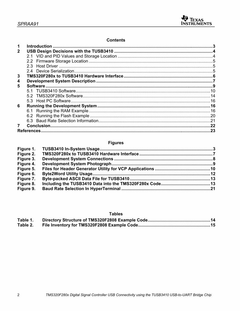
5.1 TUSB3410 Software
When using the VCP driver, software for the TUSB3410 is provided by TI in reference [3]. The user should download this from the TI website (www.ti.com). The software download consists of the files shown in Figure 5.
Figure 5. Files for Header Generator Utility for VCP Applications
The files of interest are as follows:
• Umpe3410.i51 – This is the actual executable firmware for the TUSB3410. This file is not user editable.
• VCP-3410-FW_in_EEPROM.CFG – This ASCII file contains the USB descriptors that will be used by the TUSB3410. The user can edit this file to customize the descriptors.
• Header.exe – This utility builds a single downloadable binary file for the TUSB3410 that contains the USB descriptor information specified in the .CFG file, and the executable firmware contained in the .i51 file. The resulting binary file is what the TMS320F2808 will download to the TUSB3410 at boot time.
• GOBIN.BAT – Windows command line batch file that the user should use to invoke Header.exe. This file can be viewed with a text editor.
The following steps should be followed to prepare the TUSB3410 software for download from the TMS320F280x at boot time.

SPRAA91
TMS320F280x Digital Signal Controller USB Connectivity using the TUSB3410 USB-to-UART Bridge Chip 11
Step 1: Download and unzip the “Texas Instruments USB I2C EEPROM Header Generator Utility for VCP Applications (SLLC251)” from the TI website, www.ti.com.
This is reference [3] in this application report. The easiest way to locate this on the TI website is to search using the literature number (SLLC251) in the keyword search box. Unzipping the archive will create a folder called “Binaries” that contains the files depicted in Figure 5.
Step 2: Edit VCP-3410-FW_in_EEPROM.CFG to choose the desired USB descriptors
There are numerous descriptor values in VCP-3410-FW_in_EEPROM.CFG. For the purpose of replicating the demo system in this application report, the user need not edit the file at all. It is worth pointing out though that the VID and PID are selected in this file:
; Step 2 - Create descriptor blocks ; DESCRIPTOR_BLOCK USB_DEVICE_DESCRIPTOR ; 0x12, ; size of this descriptor in bytes 0x01, ; device descriptor type 0x10, 0x01 ; USB spec 1.10 0xff, ; device class is vendor-specific 0x00 ; no sub-classes 0x00 ; no protocol 0x08 ; 8 bytes in endpoint 0 0x51, 0x04 ; vendor ID: 0x0451 (TI's VID) <-- ** ENTER CUSTOM VID ** 0x10, 0x34 ; product ID: 0x3410 <-- ** ENTER CUSTOM PID ** 0x01, 0x01 ; device release number = 1.01 0x01, ; index of string descriptor describing manufacturer 0x02, ; index of string descriptor describing product 0x03, ; index of string descriptor describing device's serial number 0x01, ; number of possible configuration
Also, the default serial number of “TUSB3410 “ (including the 8 trailing spaces) has been specified so that device serialization will take place per Section 2.4, method #2:
;------------------------------------------------------ ; string index 3, Serial # ;------------------------------------------------------ ; 0x22, ; 34 bytes 0x03, ; DESC_TYPE_STRING 'T',0x00,'U',0x00,'S',0x00,'B',0x00, '3',0x00,'4',0x00,'1',0x00,'0',0x00, '@',0x00,'@',0x00,'@',0x00,'@',0x00, '@',0x00,'@',0x00,'@',0x00,'@',0x00 ; ; = "TUSB3410 " ; ; ** For EEPROM to be serialized, this value must not change (must be equal ; to default in the bootcode). UMP firmware in EEPROM will see this ; and replace it with unique chip ID value from 3410
SPRAA91
12 TMS320F280x Digital Signal Controller USB Connectivity using the TUSB3410 USB-to-UART Bridge Chip
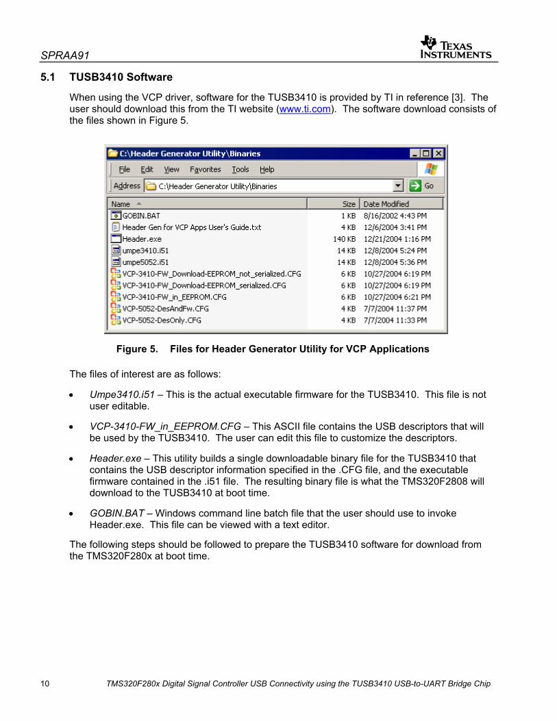
Finally, at the end of the file is where the firmware binary is included:
DESCRIPTOR_BLOCK AUTOEXEC_BINARY_FIRMWARE ; LOAD_BINARY_FILE = umpe3410.i51
Step 3: Run the Header.exe utility to create a binary output file
The Header.exe can be invoked using the GOBIN.BAT. On the command line, specify the name of the input file (i.e., VCP-3410-FW_in_EEPROM.CFG), without the filename extension:
c:> gobin VCP-3410-FW_in_EEPROM
This will create a binary file called VCP-3410-FW_in_EEPROM.bin that is about 15KB in size.
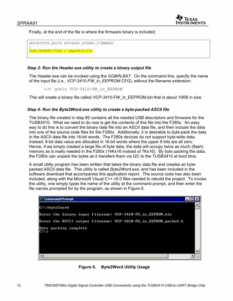
Step 4: Run the Byte2Word.exe utility to create a byte-packed ASCII file
The binary file created in step #2 contains all the needed USB descriptors and firmware for the TUSB3410. What we need to do now is get the contents of this file into the F280x. An easy way to do this is to convert the binary data file into an ASCII data file, and then include the data into one of the source code files for the F280x. Additionally, it is desirable to byte-pack the data in the ASCII data file into 16-bit words. The F280x devices do not support byte-wide data. Instead, 8-bit data value are allocated in 16-bit words where the upper 8 bits are all zero. Hence, if we simply created a large file of byte data, the data will occupy twice as much (flash) memory as is really needed in the F280x (14Kx16 instead of 7Kx16). By byte packing the data, the F280x can unpack the bytes as it transfers them via I2C to the TUSB3410 at boot time.
A small utility program has been written that takes the binary data file and creates an byte-packed ASCII data file. This utility is called Byte2Word.exe, and has been included in the software download that accompanies this application report. The source code has also been included, along with the Microsoft Visual C++ v5.0 files needed to rebuild the project. To invoke the utility, one simply types the name of the utility at the command prompt, and then enter the file names prompted for by the program, as shown in Figure 6.
Figure 6. Byte2Word Utility Usage

SPRAA91
TMS320F280x Digital Signal Controller USB Connectivity using the TUSB3410 USB-to-UART Bridge Chip 13
The resulting file contains an ASCII listing of byte-packed data, ready for download to the TUSB3410 at boot time. One can view the file with any text editor. The first 15 lines of the file are shown in Figure 7. One can identify a number of items from the original VCP-3410-FW_in_EEPROM.CFG file as well as some TUSB3410 bootloader control values (e.g., checksums). The rest of the file contains the remainder of the USB descriptor information and the firmware for the TUSB3410.
Figure 7. Byte-packed ASCII Data File for TUSB3410
Step 5: Include the byte-packed ASCII file in the source code for the TMS320F280x
A global constant array needs to be created in a source file for the TMS320F280x code, and the ASCII file used as the initialization data. It is best to use a DATA_SECTION pragma to place this array into its own named section. This allows full control over the placement of the array in the TMS320F280x memory. Figure 8 shows the relevant excerpt from the TMS320F2808 source code file main_nonBIOS.c that accompanies this application report.
//*** Create a global array that contains the bootload data for the TUSB3410 #pragma DATA_SECTION(TUSB3410BootData, "TUSB3410_Boot_Mem"); const Uint16 TUSB3410BootData[] = #include "VCP-3410-FW_in_EEPROM_packed.h" ;
Figure 8. Including the TUSB3410 Data into the TMS320F280x Code
The section “TUSB3410_Boot_Mem” can then be linked to flash memory (for example) using the linker command file for the TMS320F280x code project.
At this point, preparation of the TUSB3410 software is complete.
Used by TUSB3410 boot code to identify a valid header
Vendor ID: 0x0451 (TI's VID)
Product ID: 0x3410
Section checksum (0xcd00) used by TUSB3410 bootloader

SPRAA91
14 TMS320F280x Digital Signal Controller USB Connectivity using the TUSB3410 USB-to-UART Bridge Chip
5.2 TMS320F280x Software
A complete example code project for the eZdspF2808 board accompanies this application report. The code initializes the F2808, releases the TUSB3410 from reset using the GPIO0 pin, boots the USB descriptors and firmware into the TUSB3410, and then enters an infinite interrupt driven loop where it echoes back characters received by the SCI-A serial port. Recall that SCI-A is connected to the UART on the TUSB3410, which in turn bridges to the USB port on the host PC. So, the program actually echoes back characters transmitted via USB from the host PC.
The example code is fully self-contained, and requires no external libraries or files. The code includes and uses components from the DSP280x peripheral header file download v1.20 (see reference [10]). Table 1 shows the directory structure of the example code, while Table 2 provides a complete inventory of files provided with the example. This project was tested using Code Composer Studio™ (CCS) v3.1, with the TMS320C28x C-compiler v4.1.2.
Two different linker command files are provided with the project. F2808_nonBIOS_ram.cmd runs the entire program out of RAM on the F2808, including the boot data for the TUSB3410. F2808_nonBIOS_flash.cmd runs the entire program out of flash on the F2808. The flash version provides standalone operation of the example code. As it comes, the project uses the RAM version. To change to the flash version, simply swap out the .cmd files in the project inside Code Composer Studio.
To use the example code, load TUSB3410_example.pjt into CCS, choose the desired project configuration (‘1_Ram’ for Ram, ‘2_Flash’ for Flash), and build the project. Then load the executable into the F2808 RAM (or program the flash version of the project into on-chip flash). More details on using the example code will be given in Section 6.
Table 1. Directory Structure of TMS320F2808 Example Code
Directory Contents
\cmd Contains linker command files (.cmd files). \DSP280x_headers\include Contains the needed include files from the DSP280x Header File
structures v1.20. \DSP280x_headers\cmd Contains the needed linker command file for the DSP280x header files. \include Contains include files (.h files). \projects Contains the example project file for Code Composer Studio (.pjt file). \src Contains the source code files (.c and .asm files).
™ Code Composer Studio is a trademark of Texas Instruments Incorporated

SPRAA91
TMS320F280x Digital Signal Controller USB Connectivity using the TUSB3410 USB-to-UART Bridge Chip 15
Table 2. File Inventory for TMS320F2808 Example Code
Filename Contents
\cmd\f2808_nonBIOS_ram.cmd Main linker cmd file for RAM example \cmd\f2808_nonBIOS_flash.cmd Main linker cmd file for Flash example \DSP280x_headers\cmd\DSP280x_Headers_nonBIOS.cmd1 DSP280x header file linker cmd file \DSP280x_headers\include\DSP280x_Adc.h1 Part of DSP280x header files \DSP280x_headers\include\DSP280x_CpuTimers.h1 Part of DSP280x header files \DSP280x_headers\include\DSP280x_DevEmu.h1 Part of DSP280x header files \DSP280x_headers\include\DSP280x_Device.h1 Part of DSP280x header files \DSP280x_headers\include\DSP280x_ECan.h1 Part of DSP280x header files \DSP280x_headers\include\DSP280x_ECap1 Part of DSP280x header files \DSP280x_headers\include\DSP280x_EPwm1 Part of DSP280x header files \DSP280x_headers\include\DSP280x_EQep1 Part of DSP280x header files \DSP281x_headers\include\DSP280x_Gpio.h1 Part of DSP280x header files \DSP280x_headers\include\DSP280x_I2c.h1 Part of DSP280x header files \DSP280x_headers\include\DSP280x_PieCtrl.h1 Part of DSP280x header files \DSP280x_headers\include\DSP280x_PieVect.h1 Part of DSP280x header files \DSP280x_headers\include\DSP280x_Sci.h1 Part of DSP280x header files \DSP280x_headers\include\DSP280x_Spi.h1 Part of DSP280x header files \DSP280x_headers\include\DSP280x_SysCtrl.h1 Part of DSP280x header files \DSP280x_headers\include\DSP280x_XIntrupt.h1 Part of DSP280x header files \include\DSP280x_DefaultIsr.h1 Part of DSP280x header files \include\TUSB3410_nonBIOS.h Main include file for the project \include\VCP-3410-FW_in_EEPROM_packed.h Data for bootloading the TUSB3410 \projects\TUSB3410_example.pjt Code Composer Studio project file \src\CodeStartBranch.asm F2808 Bootloader destination target \src\DefaultIsr_nonBIOS.c Interrupt service routines \src\DSP280x_GlobalVariableDefs.c1 Part of DSP280x header files \src\Eeprom.c EEPROM memory driver for F280x \src\Gpio.c GPIO initialization function \src\I2c.c I2C port initialization function \src\main_nonBIOS.c Main function \src\passwords.asm CSM passwords (Flash example only) \src\PieCtrl_nonBIOS.c PIE initialization function \src\PieVect_nonBIOS.c PIE vector initialization table
-- table continued on next page --

SPRAA91
16 TMS320F280x Digital Signal Controller USB Connectivity using the TUSB3410 USB-to-UART Bridge Chip
\src\Sci.c SCI-A initialization function \src\SetDBGIER.asm Utility function \src\SysCtrl.c F280x CPU initialization function \disclaimer.txt Documentation file \readme.txt Documentation file
Table 2 Notes: 1 This file is identical to the file of the same name found in the DSP280x peripheral header file download
(see reference [10]).
5.3 Host PC Software
The VCP drivers for Windows based PC’s are provided in reference [4]. The user should download them from the TI website (www.ti.com) and install them according to the instructions provided therein.
A terminal program for the PC will also be needed (in order to send characters to the virtual COM port, and have them echoed back from the TMS320F2808 via the USB link). Microsoft HyperTerminal is one such program that is suitable for this purpose. It is part of the Microsoft Windows operating system, and one should find it on the Start menu under Programs→Accessories→Communications.
6 Running the Development System At this point, the user should have the development system connected per Figure 3, the TUSB3410 firmware prepared and integrated into the TMS320F2808 code build per Sections 5.1 and 5.2, and the VCP drivers installed on their PC per Section 5.3. The user is assumed familiar with the use of the CCS development environment for the TMS320F280x. Section 6.1 provides instructions for operating the development system with the RAM version of the example TMS320F2808 software provided. The flash version is briefly discussed in Section 6.2, and information on Baud rate selection is provided in Section 6.3.
6.1 Running the RAM Example
Step 1. Starting point – Power off and dip-switch setting check.
Start with the power disconnected from the eZdspF2808 board, and also disconnect the USB cable from the TUSB3410. The TUSB3410 actually gets its power from the USB port on the PC (and not from the eZdspF2808), so disconnecting the USB cable turns off power to the TUSB3410. Select the following dip-switch settings on the eZdspF2808 board:
SW1.1 = ON (CLOSED)
SW1.2 = OFF (OPEN)
SW1.3 = ON (CLOSED)
SW2.1 = ON (CLOSED)
SW2.2 = ON (CLOSED)
Selects jump-to-M0 boot.
Connects SCI-A pins through the RS232 transceiver to the D9 connector P10.

SPRAA91
TMS320F280x Digital Signal Controller USB Connectivity using the TUSB3410 USB-to-UART Bridge Chip 17
Step 2. Power-up the eZdspF2808.
Connect the 5V power supply to the eZdspF2808 board.
Step 3. Connect the USB cable to the TUSB3410.
This will power-up the TUSB3410. It will be kept in reset by the 2.2K pulldown.
Step 3. Start Code Composer Studio.
You should have your emulator connected to the eZdspF2808 (either the on-board USB based emulator, or an external emulator of your choice). After starting CCS, connect to the target if not already connected (Debug→Connect).
Step 4. Build and load the F2808 code using CCS.
Open the TUSB3410_example.pjt project (Project->Open).
Select the ‘1_RAM’ project configuration.
Build the project.
Load the code into the F2808 (File→Load_Program). If you get a load error, the Code Security Module on the F2808 may be engaged and be blocking access to some of the RAM. Just reset the device (Debug→Reset_CPU), and that should clear up the problem (CCS will unlock the security module on device reset if the default 0xFFFF passwords have been used).
Step 5. Reset the F2808, and Run the Code
Reset the F2808 (Debug→Reset_CPU).
Run the code (Debug→Run).
Checkpoint: At this point, the F2808 code has started. It has initialized the F2808, has released the TUSB3410 from reset by driving GPIO0 pin high, has boot loaded the TUSB3410 through the I2C port, and is now waiting in an infinite loop in main() for an SCI-A receive interrupt.
Step 6. Determine the COM port the VCP driver has installed itself as on your PC.
In the Windows Control Panel, select the System icon, and then click Device Manager. In Device Manager, Scroll down to the ‘Ports (COM & LPT)’ entry, open it. The VCP driver will show as ‘USB – Serial Port (COMn)’ where COMn is the COM port it has installed itself as. In the graphic below, COM5 is being used.

SPRAA91
18 TMS320F280x Digital Signal Controller USB Connectivity using the TUSB3410 USB-to-UART Bridge Chip
Step 7. Open a HyperTerminal Connection to the VCP port.
Start HyperTerminal on your PC (or alternately, a terminal program of your choice), and open a connection to the VCP COM port using the properties shown in the following graphic:

SPRAA91
TMS320F280x Digital Signal Controller USB Connectivity using the TUSB3410 USB-to-UART Bridge Chip 19
Terminal programs can be tricky things to configure, so the additional HyperTerminal connection settings used by the author are shown below.
SPRAA91
20 TMS320F280x Digital Signal Controller USB Connectivity using the TUSB3410 USB-to-UART Bridge Chip
Step 8. Type keystrokes on the PC, and see them echoed back.
Anything you type into HyperTerminal on the PC keyboard should now be echoed back by the F2808. To be clear, the data travel path is:
- User types a keystroke in HyperTerminal.
- HyperTerminal send the keystroke data to the VCP port.
- VCP port sends the data to the TUSB3410 via the USB link.
- TUSB3410 receives the data, and transfers it to the F2808 via the UART link.
- F2808 SCI-A receives the data, and generates a receive interrupt to the CPU.
- In the SCI-A receive interrupt service routine, the F2808 reads the received data and writes it back to the SCI-A transmit data buffer.
- F2808 SCI-A transmits the data to the TUSB3410 via the UART link.
- TUSB3410 receives the data and transmits it to the VCP port on the PC via the USB link.
- VCP port receives the data, sends it up to HyperTerminal, which in turn displays it in the HyperTerminal window.
To prove that that HyperTerminal is not simply performing a local keystroke echo, disconnect the USB cable from the TUSB3410, and type a keystroke. It will not be displayed in HyperTerminal. Not that once disconnected, you cannot simply reconnect the USB cable since the TUSB3410 will not re-enumerate the USB connection. You must reset the F2808, and start again.
6.2 Running the Flash Example
The flash example requires only slight modification of the instruction steps provided in Section 6.1 for the RAM example. In Step 1, the dip-switches should be configured for jump-to-flash mode (SW1.1, SW1.2, and SW1.3 all OFF). In Step 4, the ‘2_Flash’ project configuration should be selected, and also the code will need to be programmed into the flash using the programming utility of your choice (e.g., the C2000 Flash Programming Plug-in Tool for Code Composer Studio). The other steps are the same.
Once the flash is programmed, one could actually run the system standalone, without Code Composer Studio. Simply disconnect the emulator from the eZdspF2808, and power-cycle it (to reset the F2808). The code will start running. The steps for running HyperTerminal are the same.

SPRAA91
TMS320F280x Digital Signal Controller USB Connectivity using the TUSB3410 USB-to-UART Bridge Chip 21
6.3 Baud Rate Selection Information
The SCI-A baud rate on the TMS320F2808 can be configured by the user in the file TUSB3410_nonBIOS.h. The default baud rate is 460800 bps, which is half the TUSB3410 UART maximum rate. The baud rate of the TUSB3410 UART is configured by HyperTerminal.
Figure 9. Baud Rate Selection In HyperTerminal
The maximum baud rate supported by the TUSB3410 UART is 921600 Baud, and one will notice in the preceding graphic that HyperTerminal allows the choice of this baud rate. However, the F2808 cannot accurately achieve this baud rate with the 20 MHz input clock on the eZdspF2808 board. With the F2808 LSPCLK set to 100 MHz in SysCtrl.c to achieve maximum baud selection accuracy, the SCI baud rate divisors span the target 921600 baud rate:
BRR = 13 ⇒ 892857 Baud
BRR = 14 ⇒ 961538 Baud
The closest of these is 892857, but this differs by 3.1% from the target 921600, and bit errors will occur if communication is attempted.
To achieve 921600 Baud, one would need to use a different input clock for the F2808. For example, using a 24 MHz input clock and setting the PLL for x4 operation, the F2808 will run at 96 MHz. Using a SCI BRR value of 12, a baud rate of 923077 would be achieved. This differs by only 0.16% from the target 921600 baud rate.

SPRAA91
22 TMS320F280x Digital Signal Controller USB Connectivity using the TUSB3410 USB-to-UART Bridge Chip
7 Conclusion USB connectivity for the TMS320F280x Digital Signal Controller family can be achieved using the TUSB3410 UART to USB bridge chip. All needed USB descriptors and firmware for the TUSB3410 device are bootable from the on-chip memory of the F280x device through the I2C port, and hence an external EEPROM is not needed in the system. Efficient memory storage of the TUSB3410 boot data in the F2808 has been achieved using data byte packing. The boot data (for the VCP method firmware) is seen to occupy roughly 7K x 16 (14 Kbytes) of flash memory on the F280x.
A development system consisting of an eZdspF2808 board and a TUSB3410UARTPDK board provides an vehicle for easy evaluation of the USB connectivity. These two boards are readily available as separate Texas Instruments development kits. The hardware connections between the two boards as well as software preparation and installation to exercise a simple communication echo program over USB has been presented
On the PC side, Texas Instruments provides Virtual Communication Port drivers for the PC that provide a COM port conduit to the USB port. Firmware for the TUSB3410 is also provided to interface with the VCP driver on the PC. This application report demonstrated the use of the VCP approach to USB connectivity. If the VCP approach is not a suitable method for a particular application, an alternate USB PC driver (e.g., a Windows USB class drivers) could be used provided complementing TUSB3410 firmware is developed.

SPRAA91
TMS320F280x Digital Signal Controller USB Connectivity using the TUSB3410 USB-to-UART Bridge Chip 23
References 1. TUSB3410, TUSB3410I USB to Serial Port Controller Data Manual, Texas Instruments Inc.
(SLLS519). 2. TUSB3410UARTPDK User’s Guide, Texas Instruments Inc. (SLLU043). 3. Texas Instruments USB I2C EEPROM Header Generator Utility for VCP Applications, Texas
Instruments Inc. (SLLC251). 4. Texas Instruments Virtual COM Port Windows Drivers and Firmware, Texas Instruments Inc.
(TUSBWINVCP). 5. Source Code for the TI Virtual COM Port Windows Drivers and Firmware, Texas Instruments
Inc. (TUSBWINVCP-SRCCODE). 6. USB/Serial Applications Using TUSB3410/5052 and the VCP Software, Texas Instruments
Inc. (SLLA170). 7. VIDs, PIDs, and Firmware: Design Decisions when Using TI USB Device Controllers, Texas
Instruments Inc. (SLLA154). 8. TMS320F2808, TMS320F2806, TMS320F2801, UCD9501 Digital Signal Processors Data
Manual, Texas Instruments Inc. (SPRS230). 9. TMS320x280x Inter-Integrated Circuit (I2C) Module Reference Guide, Texas Instruments
Inc. (SPRU721). 10. C280x C/C++ Header Files and Peripheral Example Code, Texas Instruments Inc.
(SPRC191). 11. The I2C-Bus Specification version 2.1 – January 2000, Phillips Semiconductors, document
9398 393 40011.

IMPORTANT NOTICE
Texas Instruments Incorporated and its subsidiaries (TI) reserve the right to make corrections, modifications, enhancements, improvements, and other changes to its products and services at any time and to discontinue any product or service without notice. Customers should obtain the latest relevant information before placing orders and should verify that such information is current and complete. All products are sold subject to TI’s terms and conditions of sale supplied at the time of order acknowledgment. TI warrants performance of its hardware products to the specifications applicable at the time of sale in accordance with TI’s standard warranty. Testing and other quality control techniques are used to the extent TI deems necessary to support this warranty. Except where mandated by government requirements, testing of all parameters of each product is not necessarily performed. TI assumes no liability for applications assistance or customer product design. Customers are responsible for their products and applications using TI components. To minimize the risks associated with customer products and applications, customers should provide adequate design and operating safeguards. TI does not warrant or represent that any license, either express or implied, is granted under any TI patent right, copyright, mask work right, or other TI intellectual property right relating to any combination, machine, or process in which TI products or services are used. Information published by TI regarding third-party products or services does not constitute a license from TI to use such products or services or a warranty or endorsement thereof. Use of such information may require a license from a third party under the patents or other intellectual property of the third party, or a license from TI under the patents or other intellectual property of TI. Reproduction of information in TI data books or data sheets is permissible only if reproduction is without alteration and is accompanied by all associated warranties, conditions, limitations, and notices. Reproduction of this information with alteration is an unfair and deceptive business practice. TI is not responsible or liable for such altered documentation. Resale of TI products or services with statements different from or beyond the parameters stated by TI for that product or service voids all express and any implied warranties for the associated TI product or service and is an unfair and deceptive business practice. TI is not responsible or liable for any such statements. Following are URLs where you can obtain information on other Texas Instruments products and application solutions: Products Applications Amplifiers amplifier.ti.com Audio www.ti.com/audio Data Converters dataconverter.ti.com Automotive www.ti.com/automotive DSP dsp.ti.com Broadband www.ti.com/broadband Interface interface.ti.com Digital Control www.ti.com/digitalcontrol Logic logic.ti.com Military www.ti.com/military Power Mgmt power.ti.com Optical Networking www.ti.com/opticalnetwork Microcontrollers microcontroller.ti.com Security www.ti.com/security Telephony www.ti.com/telephony Video & Imaging www.ti.com/video Wireless www.ti.com/wireless Mailing Address: Texas Instruments Post Office Box 655303 Dallas, Texas 75265
Copyright © 2006, Texas Instruments Incorporated