Embed Size (px)
Citation preview
TMS320C64x+ DSPImage/Video Processing Library
Programmer’s Reference
Literature Number: SPRUEB9 March 2006
IMPORTANT NOTICE
Texas Instruments Incorporated and its subsidiaries (TI) reserve the right to make corrections,modifications, enhancements, improvements, and other changes to its products and services at anytime and to discontinue any product or service without notice. Customers should obtain the latestrelevant information before placing orders and should verify that such information is current andcomplete. All products are sold subject to TI’s terms and conditions of sale supplied at the time of orderacknowledgment.
TI warrants performance of its hardware products to the specifications applicable at the time of salein accordance with TI’s standard warranty. Testing and other quality control techniques are used to theextent TI deems necessary to support this warranty. Except where mandated by governmentrequirements, testing of all parameters of each product is not necessarily performed.
TI assumes no liability for applications assistance or customer product design. Customers areresponsible for their products and applications using TI components. To minimize the risks associatedwith customer products and applications, customers should provide adequate design and operatingsafeguards.
TI does not warrant or represent that any license, either express or implied, is granted under any TIpatent right, copyright, mask work right, or other TI intellectual property right relating to anycombination, machine, or process in which TI products or services are used. Information published byTI regarding third-party products or services does not constitute a license from TI to use such productsor services or a warranty or endorsement thereof. Use of such information may require a license froma third party under the patents or other intellectual property of the third party, or a license from TI underthe patents or other intellectual property of TI.
Reproduction of information in TI data books or data sheets is permissible only if reproduction is withoutalteration and is accompanied by all associated warranties, conditions, limitations, and notices.Reproduction of this information with alteration is an unfair and deceptive business practice. TI is notresponsible or liable for such altered documentation.
Resale of TI products or services with statements different from or beyond the parameters stated byTI for that product or service voids all express and any implied warranties for the associated TI productor service and is an unfair and deceptive business practice. TI is not responsible or liable for any suchstatements.
Following are URLs where you can obtain information on other Texas Instruments products andapplication solutions:
Products Applications
Amplifiers amplifier.ti.com Audio www.ti.com/audio
Data Converters dataconverter.ti.com Automotive www.ti.com/automotive
DSP dsp.ti.com Broadband www.ti.com/broadband
Interface interface.ti.com Digital Control www.ti.com/digitalcontrol
Logic logic.ti.com Military www.ti.com/military
Power Mgmt power.ti.com Optical Networking www.ti.com/opticalnetwork
Microcontrollers microcontroller.ti.com Security www.ti.com/security
Telephony www.ti.com/telephony
Video & Imaging www.ti.com/video
Wireless www.ti.com/wireless
Mailing Address: Texas Instruments
Post Office Box 655303 Dallas, Texas 75265
Copyright © 2006, Texas Instruments Incorporated
iRead This First
Preface
Read This First
About This Manual
This document describes the 64x+™ Image/Video Library (IMGLIB).
Notational Conventions
This document uses the following conventions:
� Hexadecimal numbers are shown with the suffix h. For example, thefollowing number is 40 hexadecimal (decimal 64): 40h.
� Registers in this document are shown in figures and described in tables.
� Macro names are written in uppercase text; function names are written inlowercase.
� Each register figure shows a rectangle divded into fields that repre-sent the fields of the register. Each field is labeled with its bit name, itsbeginning and ending bit numbers above, and its read/write propertiesbelow. A legend explains the notation used for the properties.
� Reserved bits in a register figure designate a bit that is used for futuredevice expansion.
Related Documentation From Texas Instruments
The following books describe the C6000™ devices and related support tools.Copies of these documents are available on the Internet at www.ti.com. Tip:Enter the literature number in the search box provided at www.ti.com.
SPRU732 — TMS320C64x/C64x+ DSP CPU and Instruction SetReference Guide. Describes the CPU architecture, pipeline, instructionset, and interrupts for the TMS320C64x and TMS320C64x+ digitalsignal processors (DSPs) of the TMS320C6000 DSP family. TheC64x/C64x+ DSP generation comprises fixed-point devices in theC6000 DSP platform. The C64x+ DSP is an enhancement of the C64xDSP with added functionality and an expanded instruction set.

Trademarks
ii
SPRAA84 — TMS320C64x to TMS320C64+ CPU Migration Guide.Describes migrating from the Texas Instruments TMS320C64x digitalsignal processor (DSP) to the TMS320C64x+ DSP. The objective of thisdocument is to indicate differences between the two cores. Functionalityin the devices that is identical is not included.
Trademarks
C6000, TMS320C64x+, TMS320C64x, C64x are trademarks of TexasInstruments.
Contents
iii
Contents
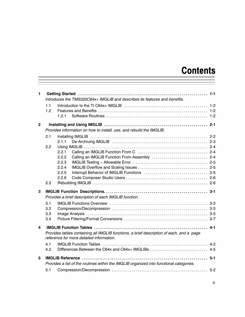
1 Getting Started 1-1. . . . . . . . . . . . . . . . . . . . . . . . . . . . . . . . . . . . . . . . . . . . . . . . . . . . . . . . . . . . . . . . . Introduces the TMS320C64x+ IMGLIB and describes its features and benefits.
1.1 Introduction to the TI C64x+ IMGLIB 1-2. . . . . . . . . . . . . . . . . . . . . . . . . . . . . . . . . . . . . . . . . . 1.2 Features and Benefits 1-2. . . . . . . . . . . . . . . . . . . . . . . . . . . . . . . . . . . . . . . . . . . . . . . . . . . . . . .
1.2.1 Software Routines 1-2. . . . . . . . . . . . . . . . . . . . . . . . . . . . . . . . . . . . . . . . . . . . . . . . . . .
2 Installing and Using IMGLIB 2-1. . . . . . . . . . . . . . . . . . . . . . . . . . . . . . . . . . . . . . . . . . . . . . . . . . . . Provides information on how to install, use, and rebuild the IMGLIB.
2.1 Installing IMGLIB 2-2. . . . . . . . . . . . . . . . . . . . . . . . . . . . . . . . . . . . . . . . . . . . . . . . . . . . . . . . . . . 2.1.1 De-Archiving IMGLIB 2-3. . . . . . . . . . . . . . . . . . . . . . . . . . . . . . . . . . . . . . . . . . . . . . . .
2.2 Using IMGLIB 2-4. . . . . . . . . . . . . . . . . . . . . . . . . . . . . . . . . . . . . . . . . . . . . . . . . . . . . . . . . . . . . . 2.2.1 Calling an IMGLIB Function From C 2-4. . . . . . . . . . . . . . . . . . . . . . . . . . . . . . . . . . . 2.2.2 Calling an IMGLIB Function From Assembly 2-4. . . . . . . . . . . . . . . . . . . . . . . . . . . . 2.2.3 IMGLIB Testing − Allowable Error 2-5. . . . . . . . . . . . . . . . . . . . . . . . . . . . . . . . . . . . . . 2.2.4 IMGLIB Overflow and Scaling Issues 2-5. . . . . . . . . . . . . . . . . . . . . . . . . . . . . . . . . . . 2.2.5 Interrupt Behavior of IMGLIB Functions 2-5. . . . . . . . . . . . . . . . . . . . . . . . . . . . . . . . 2.2.6 Code Composer Studio Users 2-6. . . . . . . . . . . . . . . . . . . . . . . . . . . . . . . . . . . . . . . . .
2.3 Rebuilding IMGLIB 2-6. . . . . . . . . . . . . . . . . . . . . . . . . . . . . . . . . . . . . . . . . . . . . . . . . . . . . . . . . .
3 IMGLIB Function Descriptions 3-1. . . . . . . . . . . . . . . . . . . . . . . . . . . . . . . . . . . . . . . . . . . . . . . . . . . . Provides a brief description of each IMGLIB function.
3.1 IMGLIB Functions Overview 3-2. . . . . . . . . . . . . . . . . . . . . . . . . . . . . . . . . . . . . . . . . . . . . . . . . 3.2 Compression/Decompression 3-3. . . . . . . . . . . . . . . . . . . . . . . . . . . . . . . . . . . . . . . . . . . . . . . . 3.3 Image Analysis 3-5. . . . . . . . . . . . . . . . . . . . . . . . . . . . . . . . . . . . . . . . . . . . . . . . . . . . . . . . . . . . . 3.4 Picture Filtering/Format Conversions 3-7. . . . . . . . . . . . . . . . . . . . . . . . . . . . . . . . . . . . . . . . . .
4 IMGLIB Function Tables 4-1. . . . . . . . . . . . . . . . . . . . . . . . . . . . . . . . . . . . . . . . . . . . . . . . . . . . . . . . . Provides tables containing all IMGLIB functions, a brief description of each, and a page reference for more detailed information.
4.1 IMGLIB Function Tables 4-2. . . . . . . . . . . . . . . . . . . . . . . . . . . . . . . . . . . . . . . . . . . . . . . . . . . . . 4.2 DIfferences Between the C64x and C64x+ IMGLIBs 4-5. . . . . . . . . . . . . . . . . . . . . . . . . . . . .
5 IMGLIB Reference 5-1. . . . . . . . . . . . . . . . . . . . . . . . . . . . . . . . . . . . . . . . . . . . . . . . . . . . . . . . . . . . . . . Provides a list of the routines within the IMGLIB organized into functional categories.
5.1 Compression/Decompression 5-2. . . . . . . . . . . . . . . . . . . . . . . . . . . . . . . . . . . . . . . . . . . . . . . .
Contents
iv
A Performance and Support A-1. . . . . . . . . . . . . . . . . . . . . . . . . . . . . . . . . . . . . . . . . . . . . . . . . . . . . . . A.1 Performance Considerations A-2. . . . . . . . . . . . . . . . . . . . . . . . . . . . . . . . . . . . . . . . . . . . . . . . . A.2 IMGLIB Software Updates A-3. . . . . . . . . . . . . . . . . . . . . . . . . . . . . . . . . . . . . . . . . . . . . . . . . . . A.3 IMGLIB Customer Support A-3. . . . . . . . . . . . . . . . . . . . . . . . . . . . . . . . . . . . . . . . . . . . . . . . . . .
B Glossary B-1. . . . . . . . . . . . . . . . . . . . . . . . . . . . . . . . . . . . . . . . . . . . . . . . . . . . . . . . . . . . . . . . . . . . . . . .
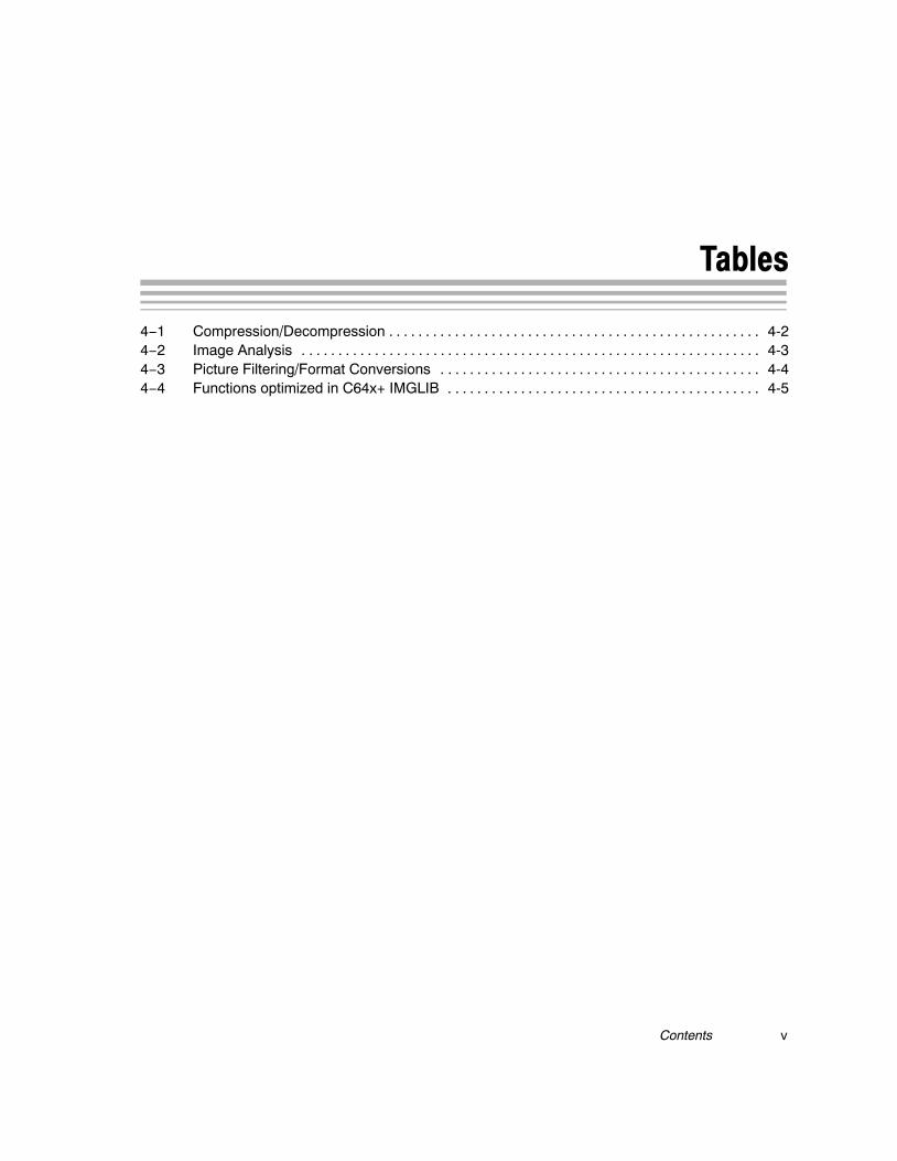
Tables
vContents
Tables
4−1 Compression/Decompression 4-2. . . . . . . . . . . . . . . . . . . . . . . . . . . . . . . . . . . . . . . . . . . . . . . . . . . 4−2 Image Analysis 4-3. . . . . . . . . . . . . . . . . . . . . . . . . . . . . . . . . . . . . . . . . . . . . . . . . . . . . . . . . . . . . . . 4−3 Picture Filtering/Format Conversions 4-4. . . . . . . . . . . . . . . . . . . . . . . . . . . . . . . . . . . . . . . . . . . . 4−4 Functions optimized in C64x+ IMGLIB 4-5. . . . . . . . . . . . . . . . . . . . . . . . . . . . . . . . . . . . . . . . . . .

vi
1-1
Getting Started
This chapter introduces the C64x+ Image/Video Library (IMGLIB) anddescribes its features and benefits.
Topic Page
1.1 Introduction to the TI C64x+ IMGLIB 1-2. . . . . . . . . . . . . . . . . . . . . . . . . . . .
1.2 Features and Benefits 1-2. . . . . . . . . . . . . . . . . . . . . . . . . . . . . . . . . . . . . . . . .
Chapter 1
Introduction to the TI C64x+ IMGLIB
1-2
1.1 Introduction to the TI C64x+ IMGLIB
The Texas Instruments C64x+ IMGLIB is an optimized Image/VideoProcessing Functions Library for C programmers using TMS320C64x+devices. It includes many C-callable, assembly-optimized, general-purposeimage/video processing routines. These routines are typically used incomputationally intensive real-time applications where optimal executionspeed is critical. By using these routines, you can achieve execution speedsconsiderably faster than equivalent code written in standard ANSI C language.In addition, by providing ready-to-use DSP functions, TI IMGLIB cansignificantly shorten your image/video processing application developmenttime.
1.2 Features and Benefits
The TI C64x+ IMGLIB contains commonly used image/video processingroutines. Source code is provided that allows you to modify functions to matchyour specific needs.
IMGLIB features include:
� Optimized assembly code routines� C and linear assembly source code� C-callable routines fully compatible with the TI C6x compiler� Benchmarks (cycles and code size)� Tested against reference C model
1.2.1 Software Routines
The rich set of software routines included in the IMGLIB are organized intothree different functional categories as follows:
� Compression and decompression� Image analysis� Picture filtering/format conversions
Introduction to the TI C64x+ IMGLIB / Features and Benefits
2-1
Installing and Using IMGLIB
This chapter provides information on how to install, use, and rebuild IMGLIB.
Topic Page
2.1 Installing IMGLIB 2-2. . . . . . . . . . . . . . . . . . . . . . . . . . . . . . . . . . . . . . . . . . . . . .
2.2 Using IMGLIB 2-4. . . . . . . . . . . . . . . . . . . . . . . . . . . . . . . . . . . . . . . . . . . . . . . . .
2.3 Rebuilding IMGLIB 2-6. . . . . . . . . . . . . . . . . . . . . . . . . . . . . . . . . . . . . . . . . . . .
Chapter 2
Installing IMGLIB
2-2
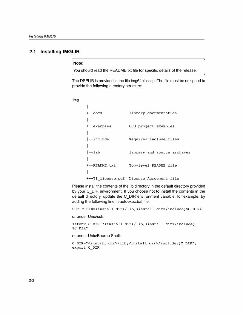
2.1 Installing IMGLIB
Note:
You should read the README.txt file for specific details of the release.
The DSPLIB is provided in the file img64plus.zip. The file must be unzipped toprovide the following directory structure:
img
|
+−−docs library documentation
|
+−−examples CCS project examples
|
|−−include Required include files
|
|−−lib library and source archives
|
+−−README.txt Top−level README file
|
+−−TI_license.pdf License Agreement file
Please install the contents of the lib directory in the default directory providedby your C_DIR environment. If you choose not to install the contents in thedefault directory, update the C_DIR environment variable, for example, byadding the following line in autoexec.bat file:
SET C_DIR=<install_dir>/lib;<install_dir>/include;%C_DIR%
or under Unix/csh:
setenv C_DIR ”<install_dir>/lib;<install_dir>/include;$C_DIR”
or under Unix/Bourne Shell:
C_DIR=”<install_dir>/lib;<install_dir>/include;$C_DIR”;export C_DIR
Installing IMGLIB
2-3 Installing and Using IMGLIB
2.1.1 De-Archiving IMGLIB
The lib directory contains the library archive and the source archive. Pleaseinstall the contents of the lib directory in the default directory provided by yourC_DIR environment. If you choose to install the contents in a differentdirectory, update the C_DIR environment variable, for example, by adding thefollowing line in autoexec.bat file:
SET C_DIR=<install_dir>/lib;<install_dir>/include;%C_DIR%
or under Unix/csh:
setenv C_DIR ”<install_dir>/lib;<install_dir>/include; $C_DIR”
or under Unix/Bourne Shell:
C_DIR=”<install_dir>/lib;<install_dir>/include;$C_DIR” ;export C_DIR
Using IMGLIB
2-4
2.2 Using IMGLIB
2.2.1 Calling an IMGLIB Function From C
In addition to correctly installing the IMGLIB software, you must follow thesesteps to include an IMGLIB function in your code:
� Include the function header file corresponding to the IMGLIB function
� Link your code with img64plus.lib
� Use the correct linker command file for your platform. Note that mostfunctions in img64plus.lib are written assuming little endian mode ofoperation.
For example, if you want to call the IMG_fdct_8x8 IMGLIB function, you wouldadd:
#include <IMG_fdct_8x8.h>
in your C file, and compile and link using:
cl6x main.c –z –o IMG_fdct_8x8_drv.out –lrts64plus.lib –limg64plus.lib
2.2.1.1 Code Composer Studio Users
Assuming your C_DIR environment is correctly set up (as mentioned inSection 2.1, Installing IMGLIB), you must add IMGLIB in the Code ComposerStudio environment by selecting Add Files to Project from the Project menu,and choosing img64plus.lib from the list of libraries under the c6400\imglibfolder. Also, ensure that you have linked to the correct runtime support library.
2.2.2 Calling an IMGLIB Function From Assembly
The C64x+ IMGLIB functions were written to be used from C. Calling thefunctions from Assembly language source code is possible as long as thecalling function conforms to the Texas Instruments C6000 C-compiler callingconventions. See Section 8, Runtime Environment, of TMS320C6000Optimizing C Compiler User’s Guide (SPRU187).
Using IMGLIB
2-5 Installing and Using IMGLIB
2.2.3 IMGLIB Testing − Allowable Error
IMGLIB is tested under the Code Composer Studio environment against areference C implementation. Test routines that deal with fixed-point typeresults expect identical results between Reference C implementation and itsAssembly implementation. The test routines that deal with floating pointresults typically allow an error margin of 0.000001 when comparing the resultsof reference C code and IMGLIB assembly code.
2.2.4 IMGLIB Overflow and Scaling Issues
The IMGLIB functions implement the exact functionality of the reference Ccode. You must conform to the range requirements specified in the functionAPI, as well as restricting the input range so that the outputs do not overflow.
2.2.5 Interrupt Behavior of IMGLIB Functions
All of the functions in this library are designed to be used in systems withinterrupts. That is, it is not necessary to disable interrupts when calling any ofthese functions. The functions in the library will disable interrupts as needed toprotect the execution of code in tight loops and so on. Functions in this libraryfall into three categories:
� Fully-interruptible: These functions do not disable interrupts. Interruptsare blocked by at most 5 to 10 cycles at a time (not counting stalls) bybranch delay slots.
� Partially-interruptible: These functions disable interrupts for longperiods of time, with small windows of interruptibility. Examples include afunction with a nested loop, where the inner loop is non-interruptible andthe outer loop permits interrupts between executions of the inner loop.
� Non-interruptible: These functions disable interrupts for nearly theirentire duration. Interrupts may happen for a short time during their setupand exit sequence.
Note that all three function categories tolerate interrupts. That is, an interruptcan occur at any time without affecting the function correctness. Theinterruptibility of the function only determines how long the kernel might delaythe processing of the interrupt.

Rebuilding IMGLIB
2-6
2.2.6 Code Composer Studio Users
If you set up a project with Code Composer Studio, you can add IMGLIB byselecting Add Files to Project from the Project menu, and choosingimg64plus.lib from the list of libraries under the c6400\imglib folder. Also,ensure that you have linked to the correct runtime support library by includingthe following lines in your linker command file:
−lrts64plus.lib
−limg64plus.lib
The include directory contains the header files necessary to be included in theC code when you call an IMGLIB function from C code.
2.3 Rebuilding IMGLIB
If you would like to rebuild IMGLIB (for example, because you modified thesource file contained in the archive), you must use the mk6x utility as follows:
mk6x img64plus.src −mv64plus −l img64plus.lib
3-1
IMGLIB��Function���Descriptions�
This chapter provides a brief description of each IMGLIB function listed in threecategories. It also provides representative examples of the functionapplication.
Topic Page
3.1 IMGLIB Functions Overview 3-2. . . . . . . . . . . . . . . . . . . . . . . . . . . . . . . . . . .
3.2 Compression/Decompression 3-3. . . . . . . . . . . . . . . . . . . . . . . . . . . . . . . . . .
3.3 Image Analysis 3-5. . . . . . . . . . . . . . . . . . . . . . . . . . . . . . . . . . . . . . . . . . . . . . .
3.4 Picture Filtering/Format Conversions 3-7. . . . . . . . . . . . . . . . . . . . . . . . . . .
Chapter 3
IMGLIB Functions Overview
3-2
3.1 IMGLIB Functions Overview
The C64x+ IMGLIB provides a collection of C-callable high performanceroutines that can serve as key enablers for a wide range of image/videoprocessing applications. These functions are representative of the highperformance capabilities of the C64x+ DSPs. The following sections describesome of the functions and their applications. These are only representativeexamples; there are many alternate uses as well.
Compression/Decompression
3-3IMGLIB Function Descriptions
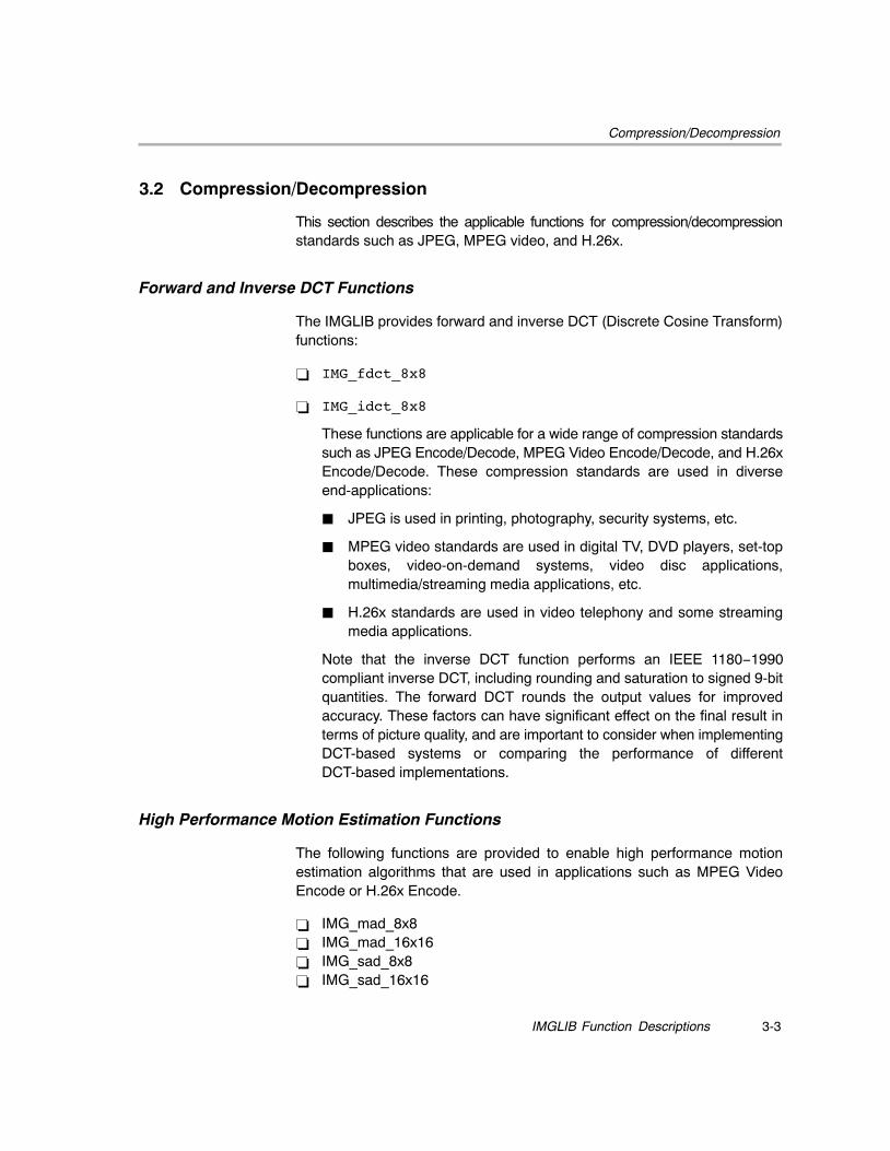
3.2 Compression/Decompression
This section describes the applicable functions for compression/decompressionstandards such as JPEG, MPEG video, and H.26x.
Forward and Inverse DCT Functions
The IMGLIB provides forward and inverse DCT (Discrete Cosine Transform)functions:
� IMG_fdct_8x8
� IMG_idct_8x8
These functions are applicable for a wide range of compression standardssuch as JPEG Encode/Decode, MPEG Video Encode/Decode, and H.26xEncode/Decode. These compression standards are used in diverseend-applications:
� JPEG is used in printing, photography, security systems, etc.
� MPEG video standards are used in digital TV, DVD players, set-topboxes, video-on-demand systems, video disc applications,multimedia/streaming media applications, etc.
� H.26x standards are used in video telephony and some streamingmedia applications.
Note that the inverse DCT function performs an IEEE 1180−1990compliant inverse DCT, including rounding and saturation to signed 9-bitquantities. The forward DCT rounds the output values for improvedaccuracy. These factors can have significant effect on the final result interms of picture quality, and are important to consider when implementingDCT-based systems or comparing the performance of differentDCT-based implementations.
High Performance Motion Estimation Functions
The following functions are provided to enable high performance motionestimation algorithms that are used in applications such as MPEG VideoEncode or H.26x Encode.
� IMG_mad_8x8� IMG_mad_16x16� IMG_sad_8x8� IMG_sad_16x16
Compression/Decompression
3-4
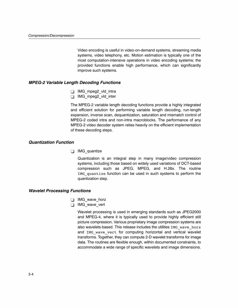
Video encoding is useful in video-on-demand systems, streaming mediasystems, video telephony, etc. Motion estimation is typically one of themost computation-intensive operations in video encoding systems; theprovided functions enable high performance, which can significantlyimprove such systems.
MPEG-2 Variable Length Decoding Functions
� IMG_mpeg2_vld_intra� IMG_mpeg2_vld_inter
The MPEG-2 variable length decoding functions provide a highly integratedand efficient solution for performing variable length decoding, run-lengthexpansion, inverse scan, dequantization, saturation and mismatch control ofMPEG-2 coded intra and non-intra macroblocks. The performance of anyMPEG-2 video decoder system relies heavily on the efficient implementationof these decoding steps.
Quantization Function
� IMG_quantize
Quantization is an integral step in many image/video compressionsystems, including those based on widely used variations of DCT-basedcompression such as JPEG, MPEG, and H.26x. The routineIMG_quantize function can be used in such systems to perform thequantization step.
Wavelet Processing Functions
� IMG_wave_horz � IMG_wave_vert
Wavelet processing is used in emerging standards such as JPEG2000and MPEG-4, where it is typically used to provide highly efficient stillpicture compression. Various proprietary image compression systems arealso wavelets-based. This release includes the utilities IMG_wave_horzand IMG_wave_vert for computing horizontal and vertical wavelettransforms. Together, they can compute 2-D wavelet transforms for imagedata. The routines are flexible enough, within documented constraints, toaccommodate a wide range of specific wavelets and image dimensions.
Image Analysis
3-5IMGLIB Function Descriptions
3.3 Image Analysis
This section provides a description of the functions that are applicable to imageanalysis standards.
Boundary and Perimeter Computation Functions
� IMG_boundary � IMG_perimeter
Boundary and Perimeter computation functions, IMG_boundary andIMG_perimeter, are provided. These are commonly used structuraloperators in machine vision applications.
Dilation and Erosion Operation Functions
� IMG_dilate_bin � IMG_erode_bin
The IMG_dilate_bin and IMG_erode_bin functions are morphologicaloperators that are used to perform Dilation and Erosion operations onbinary images. Dilation and Erosion are the fundamental building blocks ofvarious morphological operations such as Opening or Closing that can becreated from combinations of dilation and erosion. These functions areuseful in machine vision and medical imaging applications.
Histogram Function
� IMG_histogram
The histogram routine provides the ability to generate an imagehistogram. An image histogram is basically a count of the intensity levels(or some other statistic) in an image. For example, for a grayscale imagewith 8-bit pixel intensity values, the histogram will consist of 256 binscorresponding to the 256 possible pixel intensities. Each bin will contain acount of the number of pixels in the image that have that particular intensityvalue. Histogram processing (such as histogram equalization ormodification) are used in areas such as machine vision systems andimage/video content generation systems.
Edge Detection Function
� IMG_sobel
Edge Detection is a commonly-used operation in machine vision systems.Many algorithms exist for edge detection, and one of the most commonlyused ones is Sobel Edge Detection. The routine IMG_sobel provides anoptimized implementation of this edge detection algorithm.
Image Analysis
3-6
Image Thresholding Operation Functions
� IMG_thr_gt2max� IMG_thr_gt2thr� IMG_thr_le2min� IMG_thr_le2thr
Different forms of image thresholding operations are used for variousreasons in image/video processing systems. For example, one form ofthresholding may be used to convert grayscale image data to binary imagedata for input to binary morphological processing. Another form ofthresholding may be used to clip image data levels into a desired range,and yet another form of thresholding may be used to zero out low-levelperturbations in image data due to sensor noise. Thresholding is also usedfor simple segmentation in machine vision applications.
Picture Filtering/Format Conversions
3-7IMGLIB Function Descriptions
3.4 Picture Filtering/Format Conversions
This section provides a description of the functions that are applicable topicture filtering and format conversions.
Convolution Function
� IMG_conv_3x3
The convolution function is used to apply generic image filters with a 3x3filter mask, such as image smoothing, sharpening, etc.
Correlation Functions
� IMG_corr_3x3 � IMG_corr_gen
Correlation functions are provided to enable image matching. Imagematching is useful in applications such as machine vision, medicalimaging, and security/defense. Two versions of correlation functions areprovided: IMG_corr_3x3 implements highly optimized correlation forcommonly used 3x3 pixel neighborhoods, and a more general version,IMG_corr_gen, can implement correlation for user specified pixelneighborhood dimensions within documented constraints.
Error Diffusion Function
� IMG_errdif_bin
Error Diffusion with binary valued output is useful in printing applications.The most widely used error diffusion algorithm is the Floyd-Steinbergalgorithm. An optimized implementation of this algorithm is provided in thefunction, IMG_errdif_bin.
Median Filtering Function
� IMG_median_3x3
Median filtering is used in image restoration, to minimize the effects ofimpulsive noise in imagery. Applications can cover almost any area whereimpulsive noise may be a problem, including security/defense, machinevision, and video compression systems. Optimized implementation ofmedian filter for 3x3 pixel neighborhood is provided in the routineIMG_median_3x3.
Picture Filtering/Format Conversions
3-8
Pixel Expand Functions
� IMG_pix_expand � IMG_pix_expand_nM32
The routine IMG_pix_expand_nM32 has same functionality asIMG_pix_expand. It has been optimized for the C64x+ architecture. Theoptimization introduced the additional requirement, n larger or equal to 32
� IMG_pix_sat
The routines IMG_pix_expand and IMG_pix_sat respectively expand8-bit pixels to 16-bit quantities by zero extension, and saturate 16-bitsigned numbers to 8-bit unsigned numbers. They can be used to prepareinput and output data for other routines such as the horizontal and verticalscaling routines.
Color Space Conversion Functions
� IMG_ycbcr422p_rgb565
Color space conversion from YCbCr to RGB enables the display of digitalvideo data generated, for instance, by an MPEG or JPEG decoder systemon RGB displays.
� IMG_yc_demux_be16� IMG_yc_demux_le16
These routines take a packed YCrYCb color buffer in big endian or littleendian format and expands the constituent color elements into separatebuffers in little endian byte ordering.

4-1
IMGLIB�Function�Tables
This chapter provides tables containing all IMGLIB functions, a briefdescription of each, and a page reference for more detailed information.
Topic Page
4.1 IMGLIB Function Tables 4-2. . . . . . . . . . . . . . . . . . . . . . . . . . . . . . . . . . . . . . .
Table 4−1 Compression/Decompression 4-2. . . . . . . . . . . . . . . . . . . . . . . .
Table 4−2 Image Analysis 4-3. . . . . . . . . . . . . . . . . . . . . . . . . . . . . . . . . . . . . .
Table 4−3 Picture Filtering/Format Conversions 4-4. . . . . . . . . . . . . . . . .
4.2 DIfferences Between the C64x and C64x+ IMGLIBs 4-5
Chapter 4
IMGLIB Function Tables
4-2
4.1 IMGLIB Function Tables
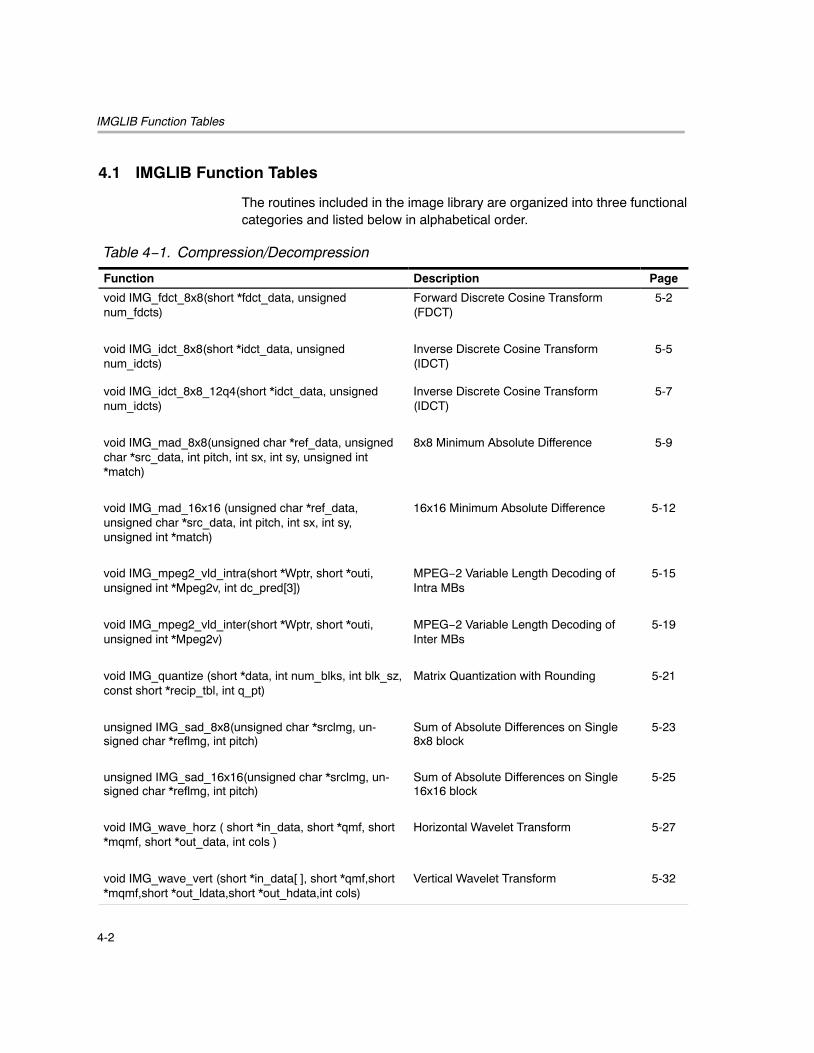
The routines included in the image library are organized into three functionalcategories and listed below in alphabetical order.
Table 4−1. Compression/Decompression
Function Description Page
void IMG_fdct_8x8(short *fdct_data, unsignednum_fdcts)
Forward Discrete Cosine Transform(FDCT)
5-2
void IMG_idct_8x8(short *idct_data, unsignednum_idcts)
Inverse Discrete Cosine Transform(IDCT)
5-5
void IMG_idct_8x8_12q4(short *idct_data, unsignednum_idcts)
Inverse Discrete Cosine Transform(IDCT)
5-7
void IMG_mad_8x8(unsigned char *ref_data, unsignedchar *src_data, int pitch, int sx, int sy, unsigned int*match)
8x8 Minimum Absolute Difference 5-9
void IMG_mad_16x16 (unsigned char *ref_data,unsigned char *src_data, int pitch, int sx, int sy,unsigned int *match)
16x16 Minimum Absolute Difference 5-12
void IMG_mpeg2_vld_intra(short *Wptr, short *outi,unsigned int *Mpeg2v, int dc_pred[3])
MPEG−2 Variable Length Decoding ofIntra MBs
5-15
void IMG_mpeg2_vld_inter(short *Wptr, short *outi,unsigned int *Mpeg2v)
MPEG−2 Variable Length Decoding ofInter MBs
5-19
void IMG_quantize (short *data, int num_blks, int blk_sz,const short *recip_tbl, int q_pt)
Matrix Quantization with Rounding 5-21
unsigned IMG_sad_8x8(unsigned char *srclmg, un-signed char *reflmg, int pitch)
Sum of Absolute Differences on Single8x8 block
5-23
unsigned IMG_sad_16x16(unsigned char *srclmg, un-signed char *reflmg, int pitch)
Sum of Absolute Differences on Single16x16 block
5-25
void IMG_wave_horz ( short *in_data, short *qmf, short*mqmf, short *out_data, int cols )
Horizontal Wavelet Transform 5-27
void IMG_wave_vert (short *in_data[ ], short *qmf,short*mqmf,short *out_ldata,short *out_hdata,int cols)
Vertical Wavelet Transform 5-32
IMGLIB Function Tables
4-3 IMGLIB Function Tables
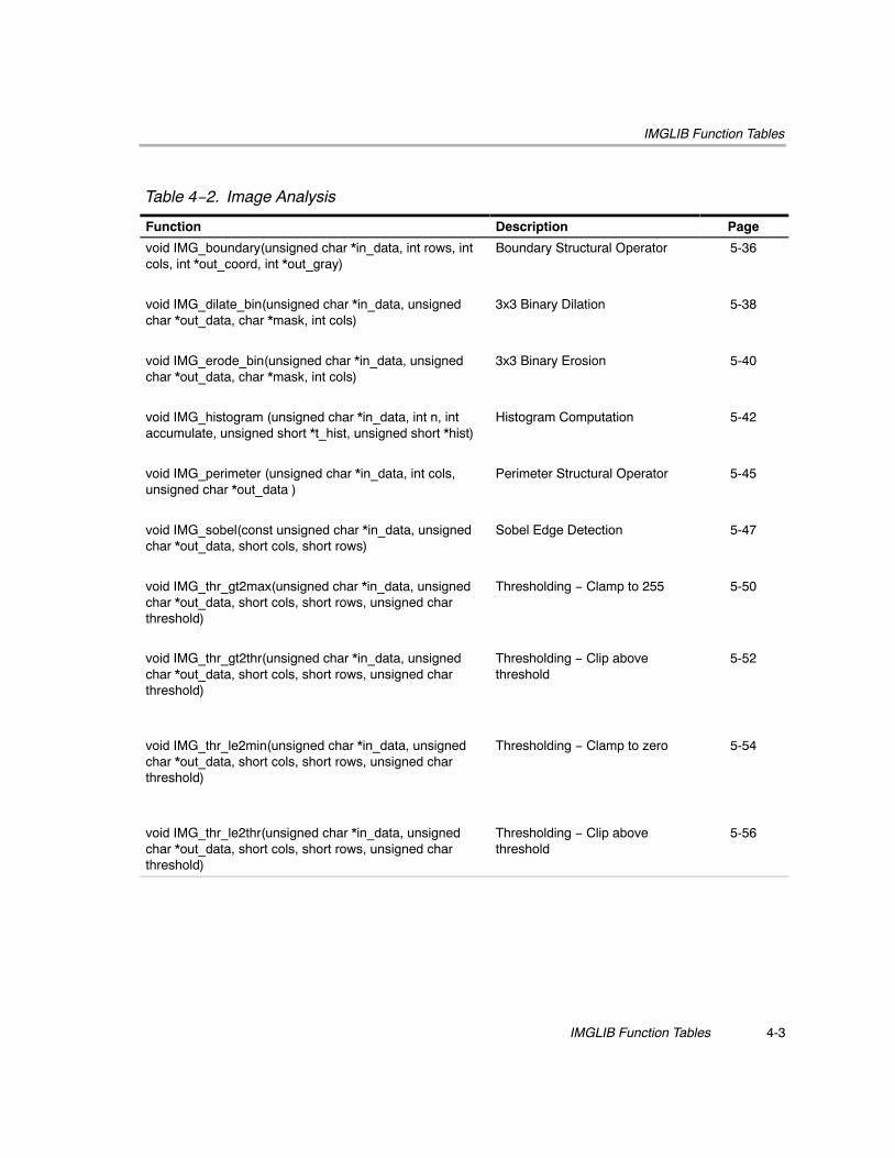
Table 4−2. Image Analysis
Function Description Page
void IMG_boundary(unsigned char *in_data, int rows, intcols, int *out_coord, int *out_gray)
Boundary Structural Operator 5-36
void IMG_dilate_bin(unsigned char *in_data, unsignedchar *out_data, char *mask, int cols)
3x3 Binary Dilation 5-38
void IMG_erode_bin(unsigned char *in_data, unsignedchar *out_data, char *mask, int cols)
3x3 Binary Erosion 5-40
void IMG_histogram (unsigned char *in_data, int n, intaccumulate, unsigned short *t_hist, unsigned short *hist)
Histogram Computation 5-42
void IMG_perimeter (unsigned char *in_data, int cols,unsigned char *out_data )
Perimeter Structural Operator 5-45
void IMG_sobel(const unsigned char *in_data, unsignedchar *out_data, short cols, short rows)
Sobel Edge Detection 5-47
void IMG_thr_gt2max(unsigned char *in_data, unsignedchar *out_data, short cols, short rows, unsigned charthreshold)
Thresholding − Clamp to 255 5-50
void IMG_thr_gt2thr(unsigned char *in_data, unsignedchar *out_data, short cols, short rows, unsigned charthreshold)
Thresholding − Clip abovethreshold
5-52
void IMG_thr_le2min(unsigned char *in_data, unsignedchar *out_data, short cols, short rows, unsigned charthreshold)
Thresholding − Clamp to zero 5-54
void IMG_thr_le2thr(unsigned char *in_data, unsignedchar *out_data, short cols, short rows, unsigned charthreshold)
Thresholding − Clip abovethreshold
5-56
IMGLIB Function Tables
4-4
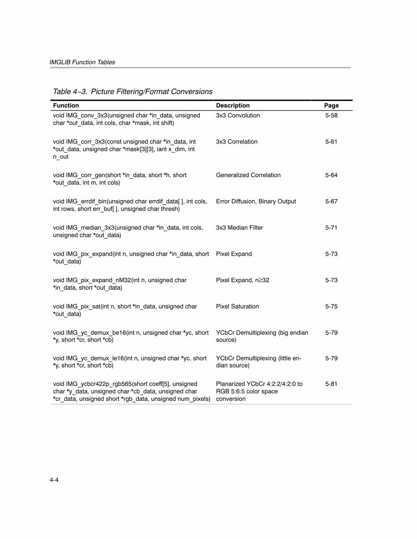
Table 4−3. Picture Filtering/Format Conversions
Function Description Page
void IMG_conv_3x3(unsigned char *in_data, unsignedchar *out_data, int cols, char *mask, int shift)
3x3 Convolution 5-58
void IMG_corr_3x3(const unsigned char *in_data, int*out_data, unsigned char *mask[3][3], iant x_dim, intn_out
3x3 Correlation 5-61
void IMG_corr_gen(short *in_data, short *h, short*out_data, int m, int cols)
Generalized Correlation 5-64
void IMG_errdif_bin(unsigned char errdif_data[ ], int cols,int rows, short err_buf[ ], unsigned char thresh)
Error Diffusion, Binary Output 5-67
void IMG_median_3x3(unsigned char *in_data, int cols,unsigned char *out_data)
3x3 Median Filter 5-71
void IMG_pix_expand(int n, unsigned char *in_data, short*out_data)
Pixel Expand 5-73
void IMG_pix_expand_nM32(int n, unsigned char*in_data, short *out_data)
Pixel Expand, n≥32 5-73
void IMG_pix_sat(int n, short *in_data, unsigned char*out_data)
Pixel Saturation 5-75
void IMG_yc_demux_be16(int n, unsigned char *yc, short*y, short *cr, short *cb)
YCbCr Demultiplexing (big endiansource)
5-79
void IMG_yc_demux_le16(int n, unsigned char *yc, short*y, short *cr, short *cb)
YCbCr Demultiplexing (little en-dian source)
5-79
void IMG_ycbcr422p_rgb565(short coeff[5], unsignedchar *y_data, unsigned char *cb_data, unsigned char*cr_data, unsigned short *rgb_data, unsigned num_pixels)
Planarized YCbCr 4:2:2/4:2:0 toRGB 5:6:5 color spaceconversion
5-81
DIfferences Between the C64x and C64x+ IMGLIBs
4-5 IMGLIB Function Tables
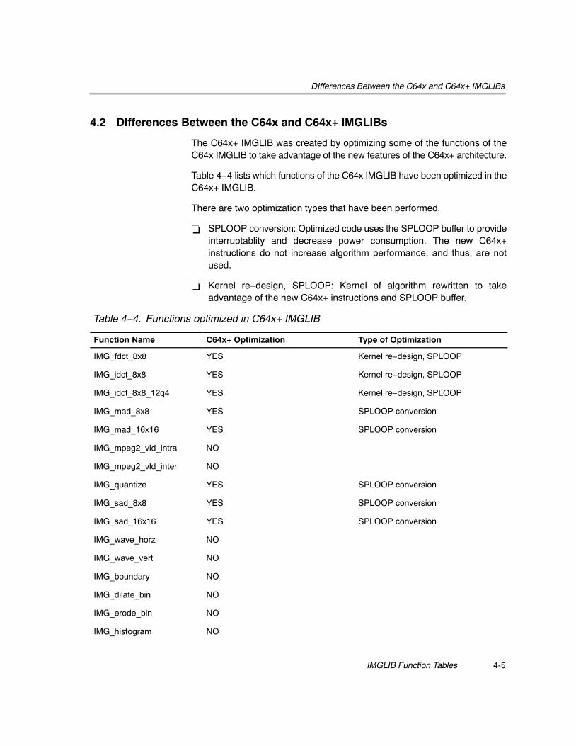
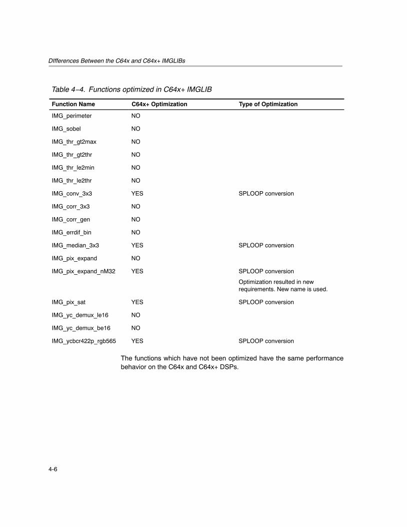
4.2 DIfferences Between the C64x and C64x+ IMGLIBs
The C64x+ IMGLIB was created by optimizing some of the functions of theC64x IMGLIB to take advantage of the new features of the C64x+ architecture.
Table 4−4 lists which functions of the C64x IMGLIB have been optimized in theC64x+ IMGLIB.
There are two optimization types that have been performed.
� SPLOOP conversion: Optimized code uses the SPLOOP buffer to provideinterruptablity and decrease power consumption. The new C64x+instructions do not increase algorithm performance, and thus, are notused.
� Kernel re−design, SPLOOP: Kernel of algorithm rewritten to takeadvantage of the new C64x+ instructions and SPLOOP buffer.
Table 4−4. Functions optimized in C64x+ IMGLIB
Function Name C64x+ Optimization Type of Optimization
IMG_fdct_8x8 YES Kernel re−design, SPLOOP
IMG_idct_8x8 YES Kernel re−design, SPLOOP
IMG_idct_8x8_12q4 YES Kernel re−design, SPLOOP
IMG_mad_8x8 YES SPLOOP conversion
IMG_mad_16x16 YES SPLOOP conversion
IMG_mpeg2_vld_intra NO
IMG_mpeg2_vld_inter NO
IMG_quantize YES SPLOOP conversion
IMG_sad_8x8 YES SPLOOP conversion
IMG_sad_16x16 YES SPLOOP conversion
IMG_wave_horz NO
IMG_wave_vert NO
IMG_boundary NO
IMG_dilate_bin NO
IMG_erode_bin NO
IMG_histogram NO
DIfferences Between the C64x and C64x+ IMGLIBs
4-6
Table 4−4. Functions optimized in C64x+ IMGLIB
Function Name Type of OptimizationC64x+ Optimization
IMG_perimeter NO
IMG_sobel NO
IMG_thr_gt2max NO
IMG_thr_gt2thr NO
IMG_thr_le2min NO
IMG_thr_le2thr NO
IMG_conv_3x3 YES SPLOOP conversion
IMG_corr_3x3 NO
IMG_corr_gen NO
IMG_errdif_bin NO
IMG_median_3x3 YES SPLOOP conversion
IMG_pix_expand NO
IMG_pix_expand_nM32 YES SPLOOP conversion
Optimization resulted in newrequirements. New name is used.
IMG_pix_sat YES SPLOOP conversion
IMG_yc_demux_le16 NO
IMG_yc_demux_be16 NO
IMG_ycbcr422p_rgb565 YES SPLOOP conversion
The functions which have not been optimized have the same performancebehavior on the C64x and C64x+ DSPs.
5-1
IMGLIB Reference
This chapter provides a list of the routines within the IMGLIB organized intofunctional categories. The functions within each category are listed inalphabetical order and include arguments, descriptions, algorithms,benchmarks, and special requirements.
Topic Page
5.1 Compression/Decompression 5-2. . . . . . . . . . . . . . . . . . . . . . . . . . . . . . . . . .
5.2 Image Analysis 5-36. . . . . . . . . . . . . . . . . . . . . . . . . . . . . . . . . . . . . . . . . . . . . .
5.3 Picture Filtering/Format Conversions 5-58. . . . . . . . . . . . . . . . . . . . . . . . . .
Chapter 5
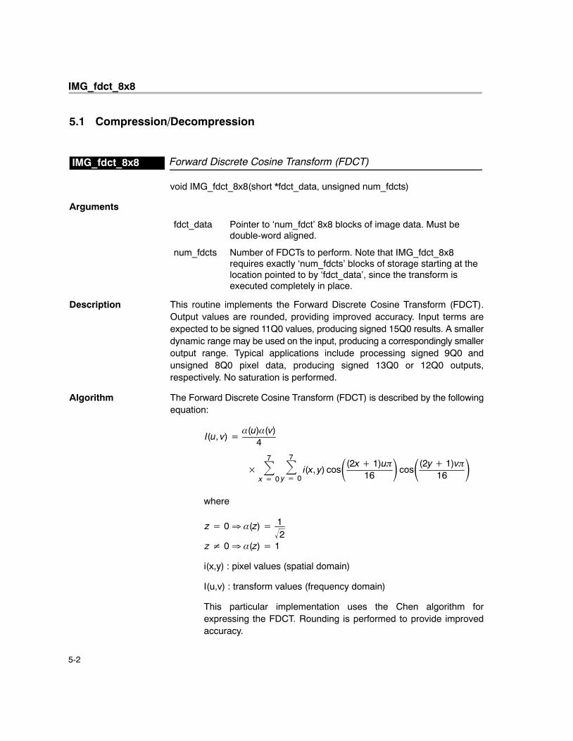
IMG_fdct_8x8
5-2
5.1 Compression/Decompression
Forward Discrete Cosine Transform (FDCT)IMG_fdct_8x8
void IMG_fdct_8x8(short *fdct_data, unsigned num_fdcts)
Arguments
fdct_data Pointer to ‘num_fdct’ 8x8 blocks of image data. Must bedouble-word aligned.
num_fdcts Number of FDCTs to perform. Note that IMG_fdct_8x8requires exactly ‘num_fdcts’ blocks of storage starting at thelocation pointed to by ‘fdct_data’, since the transform isexecuted completely in place.
Description This routine implements the Forward Discrete Cosine Transform (FDCT).Output values are rounded, providing improved accuracy. Input terms areexpected to be signed 11Q0 values, producing signed 15Q0 results. A smallerdynamic range may be used on the input, producing a correspondingly smalleroutput range. Typical applications include processing signed 9Q0 andunsigned 8Q0 pixel data, producing signed 13Q0 or 12Q0 outputs,respectively. No saturation is performed.
Algorithm The Forward Discrete Cosine Transform (FDCT) is described by the followingequation:
I(u, v) ��(u)�(v)
4
�7�
x � 0
7�
y � 0i(x, y) cos�(2x � 1)u�
16� cos�(2y � 1)v�
16�
where
z � 0 � �(z) � 12
z 0 � �(z) � 1
i(x,y) : pixel values (spatial domain)
I(u,v) : transform values (frequency domain)
This particular implementation uses the Chen algorithm forexpressing the FDCT. Rounding is performed to provide improvedaccuracy.
IMG_fdct_8x8
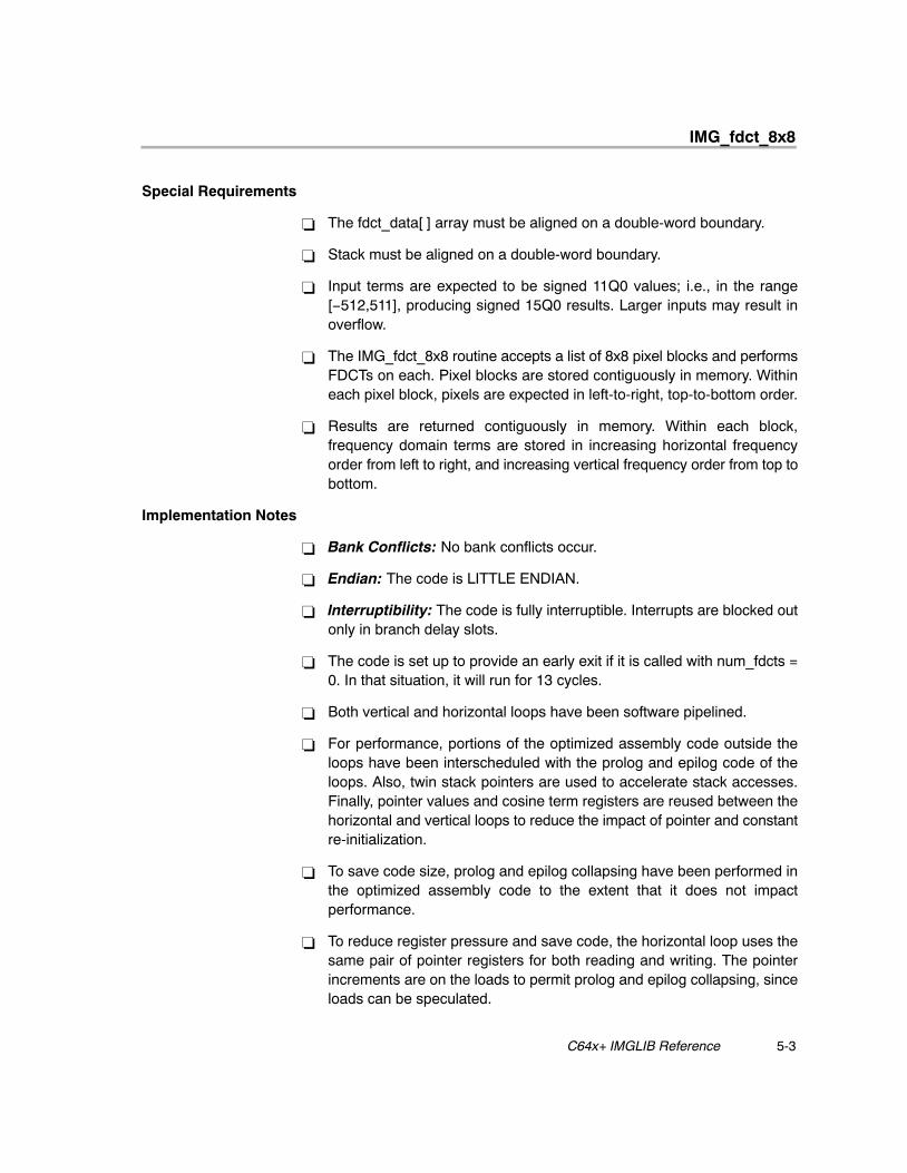
5-3 C64x+ IMGLIB Reference
Special Requirements
� The fdct_data[ ] array must be aligned on a double-word boundary.
� Stack must be aligned on a double-word boundary.
� Input terms are expected to be signed 11Q0 values; i.e., in the range[−512,511], producing signed 15Q0 results. Larger inputs may result inoverflow.
� The IMG_fdct_8x8 routine accepts a list of 8x8 pixel blocks and performsFDCTs on each. Pixel blocks are stored contiguously in memory. Withineach pixel block, pixels are expected in left-to-right, top-to-bottom order.
� Results are returned contiguously in memory. Within each block,frequency domain terms are stored in increasing horizontal frequencyorder from left to right, and increasing vertical frequency order from top tobottom.
Implementation Notes
� Bank Conflicts: No bank conflicts occur.
� Endian: The code is LITTLE ENDIAN.
� Interruptibility: The code is fully interruptible. Interrupts are blocked outonly in branch delay slots.
� The code is set up to provide an early exit if it is called with num_fdcts =0. In that situation, it will run for 13 cycles.
� Both vertical and horizontal loops have been software pipelined.
� For performance, portions of the optimized assembly code outside theloops have been interscheduled with the prolog and epilog code of theloops. Also, twin stack pointers are used to accelerate stack accesses.Finally, pointer values and cosine term registers are reused between thehorizontal and vertical loops to reduce the impact of pointer and constantre-initialization.
� To save code size, prolog and epilog collapsing have been performed inthe optimized assembly code to the extent that it does not impactperformance.
� To reduce register pressure and save code, the horizontal loop uses thesame pair of pointer registers for both reading and writing. The pointerincrements are on the loads to permit prolog and epilog collapsing, sinceloads can be speculated.
IMG_fdct_8x8
5-4
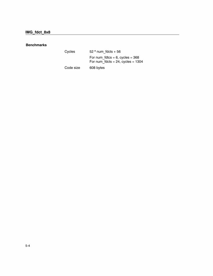
Benchmarks
Cycles 52 * num_fdcts + 56
For num_fdtcs = 6, cycles = 368For num_fdcts = 24, cycles = 1304
Code size 608 bytes
IMG_idct_8x8
5-5 C64x+ IMGLIB Reference
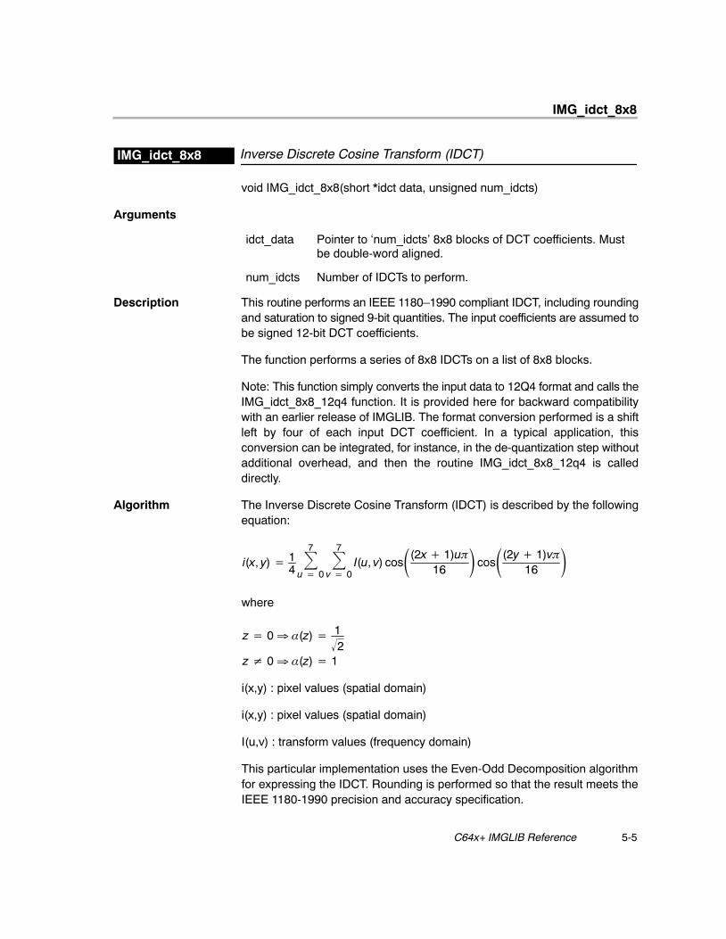
Inverse Discrete Cosine Transform (IDCT)IMG_idct_8x8
void IMG_idct_8x8(short *idct data, unsigned num_idcts)
Arguments
idct_data Pointer to ‘num_idcts’ 8x8 blocks of DCT coefficients. Mustbe double-word aligned.
num_idcts Number of IDCTs to perform.
Description This routine performs an IEEE 1180–1990 compliant IDCT, including roundingand saturation to signed 9-bit quantities. The input coefficients are assumed tobe signed 12-bit DCT coefficients.
The function performs a series of 8x8 IDCTs on a list of 8x8 blocks.
Note: This function simply converts the input data to 12Q4 format and calls theIMG_idct_8x8_12q4 function. It is provided here for backward compatibilitywith an earlier release of IMGLIB. The format conversion performed is a shiftleft by four of each input DCT coefficient. In a typical application, thisconversion can be integrated, for instance, in the de-quantization step withoutadditional overhead, and then the routine IMG_idct_8x8_12q4 is calleddirectly.
Algorithm The Inverse Discrete Cosine Transform (IDCT) is described by the followingequation:
i(x, y) � 14
7�
u � 0
7�
v � 0I(u, v) cos�(2x � 1)u�
16� cos�(2y � 1)v�
16�
where
z � 0 � �(z) � 12
z 0 � �(z) � 1
i(x,y) : pixel values (spatial domain)
i(x,y) : pixel values (spatial domain)
I(u,v) : transform values (frequency domain)
This particular implementation uses the Even-Odd Decomposition algorithmfor expressing the IDCT. Rounding is performed so that the result meets theIEEE 1180-1990 precision and accuracy specification.
IMG_idct_8x8
5-6
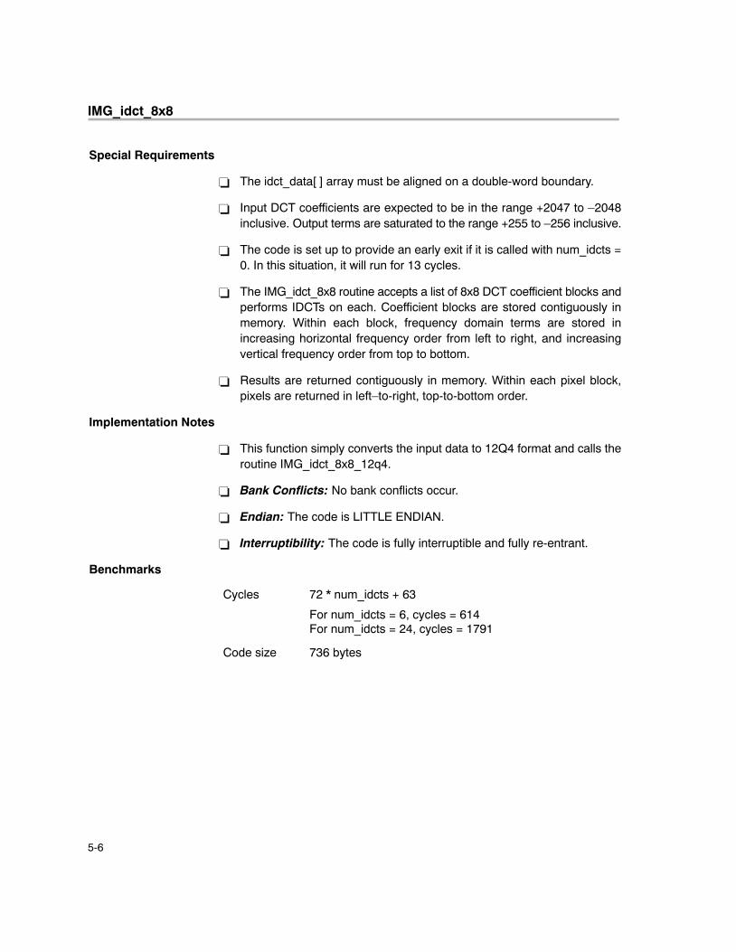
Special Requirements
� The idct_data[ ] array must be aligned on a double-word boundary.
� Input DCT coefficients are expected to be in the range +2047 to –2048inclusive. Output terms are saturated to the range +255 to –256 inclusive.
� The code is set up to provide an early exit if it is called with num_idcts =0. In this situation, it will run for 13 cycles.
� The IMG_idct_8x8 routine accepts a list of 8x8 DCT coefficient blocks andperforms IDCTs on each. Coefficient blocks are stored contiguously inmemory. Within each block, frequency domain terms are stored inincreasing horizontal frequency order from left to right, and increasingvertical frequency order from top to bottom.
� Results are returned contiguously in memory. Within each pixel block,pixels are returned in left–to-right, top-to-bottom order.
Implementation Notes
� This function simply converts the input data to 12Q4 format and calls theroutine IMG_idct_8x8_12q4.
� Bank Conflicts: No bank conflicts occur.
� Endian: The code is LITTLE ENDIAN.
� Interruptibility: The code is fully interruptible and fully re-entrant.
Benchmarks
Cycles 72 * num_idcts + 63
For num_idcts = 6, cycles = 614For num_idcts = 24, cycles = 1791
Code size 736 bytes
IMG_idct_8x8_12q4
5-7 C64x+ IMGLIB Reference
Inverse Discrete Cosine Transform(IDCT)IMG_idct_8x8_12q4
void IMG_idct_8x8_12q4(short *idct_data, unsigned num_idcts)
Arguments
idct_data Pointer to ‘num_idcts’ 8x8 blocks of DCT coefficients. Mustbe double-word aligned.
num_idcts Number of IDCTs to perform.
Description This routine performs an IEEE 1180–1990 compliant IDCT, including roundingand saturation to signed 9-bit quantities. The input coefficients are assumedto be signed 16-bit DCT coefficients in 12Q4 format.
This function performs a series of 8x8 IDCTs on a list of 8x8 blocks.
Algorithm The Inverse Discrete Cosine Transform (IDCT) is described by the followingequation:
i(x, y) � 14
7�
u � 0
7�
v � 0I(u, v) cos�(2x � 1)u�
16� cos�(2y � 1)v�
16�
where
z � 0 � �(z) � 12
z 0 � �(z) � 1
i(x,y) : pixel values (spatial domain)
i(x,y) : pixel values (spatial domain)
I(u,v) : transform values (frequency domain)
This particular implementation uses the Even-Odd Decompositionalgorithm for expressing the IDCT. Rounding is performed so that theresult meets the IEEE 1180-1990 precision and accuracyspecification.
Special Requirements
� The idct_data[ ] array must be aligned on a double-word boundary.
� Input DCT coefficients are expected to be in the range +2047 to –2048inclusive. Output terms are saturated to the range +255 to –256 inclusive;i.e., inputs are in a 12Q4 format and outputs are saturated to a 9Q0 format.
� The code is set up to provide an early exit if it is called with num_idcts =0. In this situation, it will run for 13 cycles.
IMG_idct_8x8_12q4
5-8
� The routine accepts a list of 8x8 DCT coefficient blocks and performsIDCTs on each. Coefficient blocks are stored contiguously in memory.Within each block, frequency domain terms are stored in increasinghorizontal frequency order from left to right, and increasing verticalfrequency order from top to bottom.
� Results are returned contiguously in memory. Within each pixel block,pixels are returned in left-to-right, top-to-bottom order.
Implementation Notes
� Bank Conflicts: No bank conflicts occur.
� Endian: The code is LITTLE ENDIAN.
� Interruptibility: The code is fully interruptible and fully re-entrant.
� All levels of looping are collapsed into single loops which are pipelined.The outer loop focuses on 8-pt IDCTs, whereas the inner loop controls thecolumn-pointer to handle jumps between IDCT blocks. (Thecolumn-pointer adjustment is handled by a four-phase rotating “fix-up”constant which takes the place of the original inner-loop.)
� For performance, portions of the outer-loop code have beeninter-scheduled with the prologs and epilogs of both loops. Finally, cosineterm registers are reused between the horizontal and vertical loops tosave the need for re-initialization.
� To save code size, prolog and epilog collapsing have been performed tothe extent that performance is not affected. The remaining prolog andepilog code has been inter-scheduled with code outside the loops toimprove performance.
� The code may perform speculative reads of up to 128 bytes beyond theend of the IDCT array. The speculatively accessed data is ignored.
Benchmarks
Cycles 72 * num_idcts + 63
For num_idcts = 6, cycles = 614For num_idcts = 24, cycles = 1791
Code size 736 bytes
IMG_mad_8x8
5-9 C64x+ IMGLIB Reference
8x8 Minimum Absolute DifferenceIMG_mad_8x8
void IMG_mad_8x8(const unsigned char * restrict ref_data, const unsignedchar * restrict src_data, int pitch, int sx, int sy, unsigned int * restrict match)
Arguments
*ref_data Pointer to a pixel in a reference image which constitutesthe top-left corner of the area to be searched. Thedimensions of the search area are given by (sx + 8) x (sy+ 8).
src_data[8*8] Pointer to 8x8 source image pixels. Must be wordaligned.
pitch Width of reference image.
sx Horizontal dimension of the search space.
sy Vertical dimension of the search space.
match[2] Result. Must be word aligned.
match[0]: Packed best match location. The upperhalf-word contains the horizontal pixel position and thelower half-word the vertical pixel position of the bestmatching 8x8 block in the search area. The range of thecoordinates is [0,sx−1] in the horizontal dimension and[0,sy−1] in the vertical dimension, where the location(0,0) represents the top-left corner of the search area.
match[1]: Minimum absolute difference value at the bestmatch location.
Description This routine locates the position of the top-left corner of an 8x8 pixel block in areference image which most closely matches the 8x8 pixel block in src_data[ ],using the sum of absolute differences metric. The source image block src_data[ ] is moved over a range that is sx pixels wide and sy pixels tall withina reference image that is pitch pixels wide. The pointer *ref_data points to thetop-left corner of the search area within the reference image. The matchlocation as well as the minimum absolute difference value for the match arereturned in the match[2] array. The search is performed in top-to-bottom,left-to-right order, with the earliest match taking precedence in the case of ties.
IMG_mad_8x8
5-10
Algorithm Behavioral C code for the routine is provided below: The assemblyimplementation has restrictions as noted under Special Requirements.
void IMG_mad_8x8
(
const unsigned char *restrict refImg,
const unsigned char *restrict srcImg,
int pitch, int sx, int sy,
unsigned int *restrict match
)
{
int i, j, x, y, matx, maty;
unsigned matpos, matval;
matval = ~0U;
matx = maty = 0;
for (x = 0; x < sx; x++)
for (y = 0; y < sy; y++)
{
unsigned acc = 0;
for (i = 0; i < 8; i++)
for (j = 0; j < 8; j++)
acc += abs(srcImg[i*8 + j] −
refImg[(i+y)*pitch + x + j]);
if (acc < matval)
{
matval = acc;
matx = x;
maty = y;
}
}
matpos = (0xffff0000 & (matx << 16)) |
(0x0000ffff & maty);
IMG_mad_8x8
5-11 C64x+ IMGLIB Reference
match[0] = matpos;
match[1] = matval;
}
Special Requirements
� It is assumed that src_data[ ] and ref_data[ ] do not alias in memory.� The arrays src_data[ ] and match[ ] must be word aligned.
Implementation Notes
� Bank Conflicts: No bank conflicts occur.
� Endian: The code is LITTLE ENDIAN.
� Interruptibility: The code is fully interruptible.
� The inner loops that perform the 8x8 MADs are completely unrolled andthe outer two loops are collapsed together. In addition, all source imagedata is preloaded into registers.
� The data required for any one row is brought in using nonaligned loads.SUBABS4 and DOTPU4 are used together to do the MAD computation.
� To save instructions and fit within an 8 cycle loop, the precise location ofa given match is not stored. Rather, the loop iteration that it wasencountered on is stored. A short divide loop after the search loopconverts this value into X and Y coordinates of the location.
� The inner loop comprises 64 instructions that are executed in 8 cycles,with 64 absolute differences accumulated in a single iteration. The sourcepixels are pre-read into registers. Thus, this code executes 8 instructionsper cycle, and computes 8 absolute differences per cycle.
Benchmarks
Cycles 8 * sx * sy + 66
For sx = 4, sy = 4, cycles = 194For sx = 64, sy = 32, cycles = 16,450
Code size 536 bytes
IMG_mad_16x16
5-12
16x16 Minimum Absolute DifferenceIMG_mad_16x16
void IMG_mad_16x16 (const unsigned char * restrict ref_data, const unsignedchar * restrict src_data, int pitch, int sx, int sy, unsigned int * restrict match)
Arguments
*ref_data Pointer to a pixel in a reference image which constitutesthe top-left corner of the area to be searched. Thedimensions of the search area are given by (sx + 16) x (sy+ 16).
src_data[16*16] Pointer to 16x16 source image pixels.
pitch Width of reference image.
sx Horizontal dimension of the search space.
sy Vertical dimension of the search space.
match[2] Result.
match[0]: Packed best match location. The upperhalf-word contains the horizontal pixel position and thelower half-word the vertical pixel position of the bestmatching 16x16 block in the search area. The range ofthe coordinates is [0,sx−1] in the horizontal dimensionand [0,sy−1] in the vertical dimension, where the location(0,0) represents the top-left corner of the search area.
match[1]: Minimum absolute difference value at the bestmatch location.
Description This routine locates the position of the top-left corner of an 16x16 pixel blockin a reference image which most closely matches the 16x16 pixel block insrc_data[ ], using the sum of absolute differences metric. The source imageblock src_data[ ] is moved over a range that is sx pixels wide and sy pixels tallwithin a reference image that is pitch pixels wide. The pointer *ref_data pointsto the top-left corner of the search area within the reference image. The matchlocation and the minimum absolute difference value for the match are returnedin the match[2] array.
IMG_mad_16x16
5-13 C64x+ IMGLIB Reference
Algorithm Behavioral C code for the routine is provided below: The assemblyimplementation has restrictions as noted under Special Requirements.
void IMG_mad_16x16
(
const unsigned char *restrict refImg,
const unsigned char *restrict srcImg,
int pitch, int sx, int sy,
unsigned int *restrict match
)
{
int i, j, x, y, matx, maty;
unsigned matpos, matval;
matval = ~0U;
matx = maty = 0;
for (x = 0; x < sx; x++)
for (y = 0; y < sy; y++)
{
unsigned acc = 0;
for (i = 0; i < 16; i++)
for (j = 0; j < 16; j++)
acc += abs(srcImg[i*16 + j] −
refImg[(i+y)*pitch + x + j]);
if (acc < matval)
{
matval = acc;
matx = x;
maty = y;
}
}
matpos = (0xffff0000 & (matx << 16)) |
(0x0000ffff & maty);
IMG_mad_16x16
5-14
match[0] = matpos;
match[1] = matval;
}
Special Requirements
� It is assumed that src_data[ ] and ref_data[ ] do not alias in memory.� sy must be a multiple of 2.� There are no alignment restrictions.
Implementation Notes
� Bank Conflicts: No bank conflicts occur.
� Endian: The code is LITTLE ENDIAN.
� Interruptibility: The code is fully interruptible.
� The two outer loops are merged, as are the two inner loops. The inner loopprocess 2 lines of 2 search locations in parallel.
� The search is performed in top-to-bottom, left-to-right order, with theearliest match taking precedence in the case of ties.
� Further use is made of SUBABS4 and DOTPU4. The SUBABS4 takes theabsolute difference on four 8 bit quantities packed into a 32 bit word. TheDOTPU4 performs four 8 bit wide multiplies and adds the results together.
Benchmarks
Cycles 38 * sx * sy + 20
For sx = 4, sy = 4, cycles = 628For sx = 64, sy = 32, cycles = 77,844
Code size 776 bytes
IMG_mpeg2_vld_intra
5-15 C64x+ IMGLIB Reference
MPEG-2 Variable Length Decoding of Intra MBsIMG_mpeg2_vld_intra
void IMG_mpeg2_vld_intra(const short * restrict Wptr, short * restrict outi,IMG_mpeg2_vld * restrict Mpeg2v, int dc_pred[3], int mode_12Q4, intnum_blocks, int bsbuf_words)
Arguments
Wptr[] Pointer to array that contains quantization matrix. Theelements of the quantization matrix in Wptr[] must be orderedaccording to the scan pattern used (zigzag or alternate scan).Video format 4:2:0 requires one quantization matrix of 64array elements. For formats 4:2:2 and 4:4:4, two quantizationmatrices, one for luma and one for chroma, must be specifiedin the array now containing 128 array elements.
outi[6*64] Pointer to the context object containing the codingparameters of the MB to be decoded and the current state ofthe bitstream buffer. The structure is described below.
Mpeg2v Pointer to a context structure containing coding parametersof the MB to be decoded and the current state of the bitstreambuffer.
dc_pred[3] Intra DC prediction array, the first element of dc_pred is theDC prediction for Y, the second for Cr and the third for Cb.
mode_12Q4 0: Coefficients are returned in normal 16-bit integer format.
Otherwise: Coefficients are returned in 12Q4 format (normal16-bit integer format left shifted by 4). This mode is useful fordirectly passing the coefficients into the IMG_idct_8x8routine.
num_blocks Number of blocks that the MB contains. Valid values are 6 for4:2:0, 8 for 4:2:2 and 12 for 4:4:4 format.
bsbuf_words Size of bitstream buffer in words. Must be a power of 2.Bitstream buffer must be aligned at an address boundaryequal to its size in bytes because the bitstream buffer isaddressed circularly by this routine.
Description This routine takes a bitstream of an MPEG-2 intra coded macroblock (MB) andreturns the decoded IDCT coefficients. The routine checks the coded blockpattern (cbp) and performs DC and AC coefficient decoding including variablelength decode, run-length expansion, inverse zigzag ordering,de-quantization, saturation, and mismatch control. An example program isprovided that illustrates the usage of this routine. The structureIMG_mpeg2_vld is defined as follows.
IMG_mpeg2_vld_intra
5-16
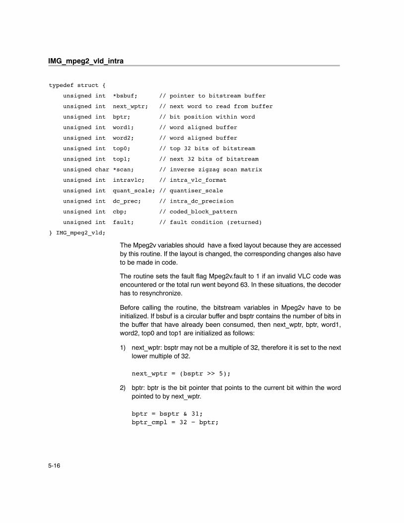
typedef struct {
unsigned int *bsbuf; // pointer to bitstream buffer
unsigned int next_wptr; // next word to read from buffer
unsigned int bptr; // bit position within word
unsigned int word1; // word aligned buffer
unsigned int word2; // word aligned buffer
unsigned int top0; // top 32 bits of bitstream
unsigned int top1; // next 32 bits of bitstream
unsigned char *scan; // inverse zigzag scan matrix
unsigned int intravlc; // intra_vlc_format
unsigned int quant_scale; // quantiser_scale
unsigned int dc_prec; // intra_dc_precision
unsigned int cbp; // coded_block_pattern
unsigned int fault; // fault condition (returned)
} IMG_mpeg2_vld;
The Mpeg2v variables should have a fixed layout because they are accessedby this routine. If the layout is changed, the corresponding changes also haveto be made in code.
The routine sets the fault flag Mpeg2v.fault to 1 if an invalid VLC code wasencountered or the total run went beyond 63. In these situations, the decoderhas to resynchronize.
Before calling the routine, the bitstream variables in Mpeg2v have to beinitialized. If bsbuf is a circular buffer and bsptr contains the number of bits inthe buffer that have already been consumed, then next_wptr, bptr, word1,word2, top0 and top1 are initialized as follows:
1) next_wptr: bsptr may not be a multiple of 32, therefore it is set to the nextlower multiple of 32.
next_wptr = (bsptr >> 5);
2) bptr: bptr is the bit pointer that points to the current bit within the wordpointed to by next_wptr.
bptr = bsptr & 31;bptr_cmpl = 32 − bptr;

IMG_mpeg2_vld_intra
5-17 C64x+ IMGLIB Reference
3) word1 and word2: Read the next 3 words from the bitstream buffer bsbuf.bsbuf_words is the size of the bitstream buffer in words (word0 is atemporary variable not passed in Mpeg2v).
word0 = bsbuf[next_wptr];
next_wptr = (next_wptr+1) & (bsbuf_words −1);
word1 = bsbuf[next_wptr];
next_wptr = (next_wptr+1) & (bsbuf_words −1);
word2 = bsbuf[next_wptr];
next_wptr = (next_wptr+1) & (bsbuf_words −1);
4) top0 and top1: Shift words word0, word1, word2 by bptr to the left so thatthe current bit becomes the left-most bit in top0 and top0 and top1 containthe next 64 bits to be decoded.
s1 = word0 << bptr;
s2 = word1 >> bptr_cmpl; /*unsigned shift*/
top0 = s1 + s2;
s3 = word1<< bptr; s4 = word2 >> bptr_cmpl; /*unsigned shift*/
top1 = s3 + s4;
Note that the routine returns the updated state of the bitstream buffervariables, top0, top1, word1, word2, bptr and next_wptr. If all other functionswhich access the bitstream in a decoder system maintain the buffer variablesin the same way, then the above initialization procedure only has to beperformed once at the beginning.
Algorithm This routine is implemented as specified in the MPEG-2 standard text (ISO/IEC 13818-2).
Special Requirements
� The bitstream must be stored in memory in 32-bit words in little Endianbyte order.
� Wptr is allowed to overrun once to detect if a decoded run causes the totalrun to exceed 63. The maximum overrun that can occur is the error mark66 because it is the highest value that can be decoded for a run value.Therefore, 67 half–words behind the weighting matrix array should bememory locations whose read access does not cause any side effects,such as peripherals.
� Note that the AMR register is set to zero on exit.
IMG_mpeg2_vld_intra
5-18
Implementation Notes
� Bank Conflicts: No bank conflicts occur.
� Endian: This code is LITTLE ENDIAN.
� Interruptibility: This code is interrupt-tolerant but not interruptible.
� The instruction NORM is used to detect the number of leading zeros orones in a code word. This value, together with additional bits extractedfrom the codeword, is then used as an index into lookup tables todetermine the length, run, level, and sign. Escape code sequences aredirectly extracted from the code word.
� DC coefficients are decoded without lookup tables by exploiting therelatively simple relationship between the number of leading zeros anddc_size and the length of the code word.
Benchmarks
Cycles 10 * (S − CB) + 55 * CB + 15 * NCB + 35
where S is the number of symbols in the MB, CB is the num-ber of coded blocks and NCB is the number of non-codedblocks (NCB = 6 − CB).
For S = 120, CB = 6, NCB = 0, cycles = 1505For S = 200, CB = 6, NCB = 0, cycles = 2305
Code size 1496 bytes
Data size 3584 bytes for lookup tables
IMG_mpeg2_vld_inter
5-19 C64x+ IMGLIB Reference
MPEG-2 Variable Length Decoding of Inter MBsIMG_mpeg2_vld_inter
void IMG_mpeg2_vld_inter(const short *Wptr, short *outi, IMG_mpeg2_vld*Mpeg2v, int mode_12Q4, int num_blocks, int bsbuf_words)
Arguments
Wptr[] Pointer to array that contains quantization matrix. Theelements of the quantization matrix in Wptr[] must beordered according to the scan pattern used (zigzag oralternate scan). Video format 4:2:0 requires onequantization matrix of 64 array elements. For formats 4:2:2and 4:4:4, two quantization matrices, one for luma and onefor chroma, must be specified in the array now containing128 array elements.
outi[6*64] Pointer to the IDCT coefficients output array (6*64elements), elements must be set to zero prior to function call.
Mpeg2v Pointer to the context object containing the codingparameters of the MB to be decoded and the current state ofthe bitstream buffer. The structure is described below.
mode_12Q4 0: Coefficients are returned in normal 16-bit integer format.
Otherwise: Coefficients are returned in 12Q4 format (normal16-bit integer format left shifted by 4). This mode is useful fordirectly passing the coefficients into the IMG_idct_8x8routine.
num_blocks Number of blocks that the MB contains. Valid values are 6 for4:2:0, 8 for 4:2:2, and 12 for 4:4:4 format.
bsbuf_words Size of bitstream buffer in words. Must be a power of 2.Bitstream buffer must be aligned at an address boundaryequal to its size in bytes because the bitstream buffer isaddressed circularly by this routine.
Description This routine takes a bitstream of an MPEG-2 non-intra coded macroblock (MB)and returns the decoded IDCT coefficients. The routine checks the codedblock pattern (cbp) and performs coefficient decoding including variable lengthdecode, run-length expansion, inverse zigzag ordering, de-quantization,saturation, and mismatch control. An example program is provided illustratingthe usage of this routine.
Description See the description of the IMG_mpeg2_vld_intra routine for furtherinformation about the usage of this routine.
Algorithm This routine is implemented as specified in the MPEG-2 standard text (ISO/IEC 13818-2).
IMG_mpeg2_vld_inter
5-20
Special Requirements
� The bitstream must be stored in memory in 32–bit words which are in littleEndian byte order.
� Wptr is allowed to overrun once to detect if a decoded run causes the totalrun to exceed 63. The maximum overrun that can occur is the error mark66 because it is the highest value that can be decoded for a run value.Therefore, 67 half-words behind the weighting matrix array should bememory locations whose read access does not cause any side effects,such as peripherals.
� Note that the AMR register is set to zero on exit.
Implementation Notes
� Bank Conflicts: No bank conflicts occur.
� Endian: This code is LITTLE ENDIAN.
� Interruptibility: This code is interrupt-tolerant but not interruptible.
� The instruction NORM is used to detect the number of leading zeros orones in a code word. This value, together with additional bits extractedfrom the codeword, is then used as an index into lookup tables todetermine the length, run, level, and sign. Escape code sequences aredirectly extracted from the code word.
� The special case of the first coefficient of a block is handled by modifyingthe prolog of the decoding loop.
Benchmarks
Cycles 10 * S + 37 * CB + 15 * NCB + 34
where S is the number of symbols in the MB, CB is the num-ber of coded blocks and NCB is the number of non-codedblocks (NCB = 6 − CB).
For S = 80, CB = 5, NCB = 1, cycles = 1032For S = 192, CB = 6, NCB = 0, cycles = 2174
Code size 1212 bytes
Data size 1792 bytes for lookup tables
IMG_quantize
5-21 C64x+ IMGLIB Reference
Matrix Quantization With RoundingIMG_quantize
void IMG_quantize (short *data, int num_blks, int blk_size, const short *recip_tbl, int q_pt)
Arguments
data[ ] Pointer to data to be quantized. Must be double-wordaligned and contain num_blks*blk_size elements.
num_blks Number of blocks to be processed. May be zero.
blk_size Block size. Must be multiple of 16 and ≥32
recip_tbl[ ] Pointer to quantization values (reciprocals) . Must bedouble-word aligned and contain blk_size elements.
q_pt Q–point of quantization values. 0 ≤ q_pt ≤ 31
Description This routine quantizes a list of blocks by multiplying their contents with asecond block of values that contains reciprocals of the quantization terms.This step corresponds to the quantization that is performed in 2-D DCT-basedcompression techniques, although the routine may be used on any signed16-bit data using signed 16-bit quantization terms.
The routine merely multiplies the contents of the quantization array recip_tbl[ ]with the data array data[ ]. Therefore, it may be used for inverse quantizationas well, by setting the Q-point appropriately.
Algorithm Behavioral C code for the routine is provided below:void IMG_quantize (short *data, int num_blks, int blk_size, const short*recip_tbl, int q_pt){ short recip; int i, j, k, quot, round; round = q_pt ? 1 << (q_pt – 1) : 0; for (i = 0; i < blk_size; i++) { recip = recip_tbl[i]; k = i; for (j = 0; j < num_blks; j++) { quot = data[k] * recip + round; data[k] = quot >> q_pt; k += blk_size; }
}}
IMG_quantize
5-22
Special Requirements
� The number of blocks, num_blks, may be zero.
� The block size, blk_size, must be at least 32 and a multiple of 16.
� The Q-point, q_pt, controls rounding and final truncation; it must be in therange 0 ≤ q_pt ≤ 31.
� Both input arrays, data[ ] and recip_tbl[ ], must be double-word aligned.
� The data[ ] array must contain num_blks * blk_size elements, and therecip_tbl[ ] array must contain blk_size elements.
Implementation Notes
� Bank Conflicts: No bank conflicts occur, regardless of the relativeorientation of recip_tbl[ ] and data[ ].
� Endian: The code is LITTLE ENDIAN.
� Interruptibility: This code is fully interruptible, with a maximum interruptlatency of 16 cycles due to branch delay slots.
� The outer loop is unrolled 16 times to allow greater amounts of work to beperformed in the inner loop. The resulting loop-nest is then collapsed andpipelined as a single loop, since the code is not bottlenecked onbandwidth.
� Reciprocals and data terms are loaded in groups of four with double-wordloads, making the best use of the available memory bandwidth.
� SSHVR is used in the M-unit to avoid an S-unit bottleneck.
� Twin stack pointers are used to speed up stack accesses.
Benchmarks
Cycles (blk_size/16) * num_blks * 8 + 26
For blk_size = 64, num_blks = 8, cycles = 282For blk_size = 256, num_blks = 24, cycles = 3098
Code size 580 bytes
IMG_sad_8x8
5-23 C64x+ IMGLIB Reference
Sum of Absolute Differences on Single 8x8 BlockIMG_sad_8x8
unsigned sad_8x8(const unsigned char * restrict srclmg, const unsigned char* restrict reflmg, int pitch)
Arguments
srcImg[64] 8x8 source block. Must be double-word aligned.
refImg[] Reference image.
pitch Width of reference image.
Description This function returns the sum of the absolute differences between the sourceblock and the 8x8 region pointed to in the reference image.
The code accepts a pointer to the 8x8 source block (srcImg), and a pointer tothe upper-left corner of a target position in a reference image (refImg). Thewidth of the reference image is given by the pitch argument.
Algorithm Behavioral C code for the routine is provided below:
unsigned sad_8x8
(
const unsigned char *restrict srcImg,
const unsigned char *restrict refImg,
int pitch
)
{
int i, j;
unsigned sad = 0;
for (i = 0; i < 8; i++)
for (j = 0; j < 8; j++)
sad += abs(srcImg[j+i*8] − refImg[j+i*pitch]);
return sad;
}
Special Requirements
� The array srcImg[64] must be aligned at a double-word boundary.

IMG_sad_8x8
5-24
Implementation Notes
� Bank Conflicts: No bank conflicts occur.� Endian: The code is ENDIAN NEUTRAL.� Interruptibility: The code is fully interruptible.
Benchmarks
Cycles 31
Code size 164 bytes
IMG_sad_16x16
5-25 C64x+ IMGLIB Reference
Sum of Absolute Differences on Single 16x16 BlockIMG_sad_16x16
unsigned sad_16x16(const unsigned char * restrict srclmg, const unsignedchar * restrict reflmg, int pitch)
Arguments
srcImg[256] 16x16 source block. Must be double-word aligned.
refImg[] Reference image.
pitch Width of reference image.
Description This function returns the sum of the absolute differences between the sourceblock and the 16x16 region pointed to in the reference image.
The code accepts a pointer to the 16x16 source block (srcImg), and a pointer tothe upper-left corner of a target position in a reference image (refImg). Thewidth of the reference image is given by the pitch argument.
Algorithm Behavioral C code for the routine is provided below:
unsigned sad_16x16
(
const unsigned char *restrict srcImg,
const unsigned char *restrict refImg,
int pitch
)
{
int i, j;
unsigned sad = 0;
for (i = 0; i < 16; i++)
for (j = 0; j < 16; j++)
sad += abs(srcImg[j+i*16] − refImg[j+i*pitch]);
return sad;
}
Special Requirements
� The array srcImg[256] must be aligned at a double-word boundary.
IMG_sad_16x16
5-26
Implementation Notes
� Bank Conflicts: No bank conflicts occur.� Endian: The code is ENDIAN NEUTRAL.� Interruptibility: The code is fully interruptible.
Benchmarks
Cycles 67
Code size 168 bytes
IMG_wave_horz
5-27 C64x+ IMGLIB Reference
Horizontal Wavelet TransformIMG_wave_horz
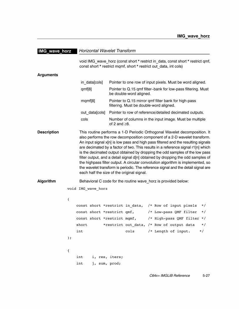
void IMG_wave_horz (const short * restrict in_data, const short * restrict qmf,const short * restrict mqmf, short * restrict out_data, int cols)
Arguments
in_data[cols] Pointer to one row of input pixels. Must be word aligned.
qmf[8] Pointer to Q.15 qmf filter–bank for low-pass filtering. Mustbe double-word aligned.
mqmf[8] Pointer to Q.15 mirror qmf filter bank for high-passfiltering. Must be double-word aligned.
out_data[cols] Pointer to row of reference/detailed decimated outputs.
cols Number of columns in the input image. Must be multipleof 2 and ≥8.
Description This routine performs a 1-D Periodic Orthogonal Wavelet decomposition. Italso performs the row decomposition component of a 2-D wavelet transform.An input signal x[n] is low pass and high pass filtered and the resulting signalsare decimated by a factor of two. This results in a reference signal r1[n] whichis the decimated output obtained by dropping the odd samples of the low passfilter output, and a detail signal d[n] obtained by dropping the odd samples ofthe highpass filter output. A circular convolution algorithm is implemented, sothe wavelet transform is periodic. The reference signal and the detail signal areeach half the size of the original signal.
Algorithm Behavioral C code for the routine wave_horz is provided below:
void IMG_wave_horz
(
const short *restrict in_data, /* Row of input pixels */
const short *restrict qmf, /* Low-pass QMF filter */
const short *restrict mqmf, /* High-pass QMF filter */
short *restrict out_data, /* Row of output data */
int cols /* Length of input. */
);
{
int i, res, iters;
int j, sum, prod;
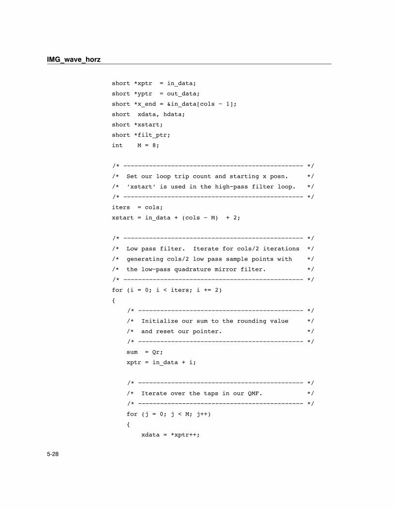
IMG_wave_horz
5-28
short *xptr = in_data;
short *yptr = out_data;
short *x_end = &in_data[cols − 1];
short xdata, hdata;
short *xstart;
short *filt_ptr;
int M = 8;
/* −−−−−−−−−−−−−−−−−−−−−−−−−−−−−−−−−−−−−−−−−−−−−−−−− */
/* Set our loop trip count and starting x posn. */
/* ’xstart’ is used in the high−pass filter loop. */
/* −−−−−−−−−−−−−−−−−−−−−−−−−−−−−−−−−−−−−−−−−−−−−−−−− */
iters = cols;
xstart = in_data + (cols − M) + 2;
/* −−−−−−−−−−−−−−−−−−−−−−−−−−−−−−−−−−−−−−−−−−−−−−−−− */
/* Low pass filter. Iterate for cols/2 iterations */
/* generating cols/2 low pass sample points with */
/* the low−pass quadrature mirror filter. */
/* −−−−−−−−−−−−−−−−−−−−−−−−−−−−−−−−−−−−−−−−−−−−−−−−− */
for (i = 0; i < iters; i += 2)
{
/* −−−−−−−−−−−−−−−−−−−−−−−−−−−−−−−−−−−−−−−−−−−−− */
/* Initialize our sum to the rounding value */
/* and reset our pointer. */
/* −−−−−−−−−−−−−−−−−−−−−−−−−−−−−−−−−−−−−−−−−−−−− */
sum = Qr;
xptr = in_data + i;
/* −−−−−−−−−−−−−−−−−−−−−−−−−−−−−−−−−−−−−−−−−−−−− */
/* Iterate over the taps in our QMF. */
/* −−−−−−−−−−−−−−−−−−−−−−−−−−−−−−−−−−−−−−−−−−−−− */
for (j = 0; j < M; j++)
{
xdata = *xptr++;
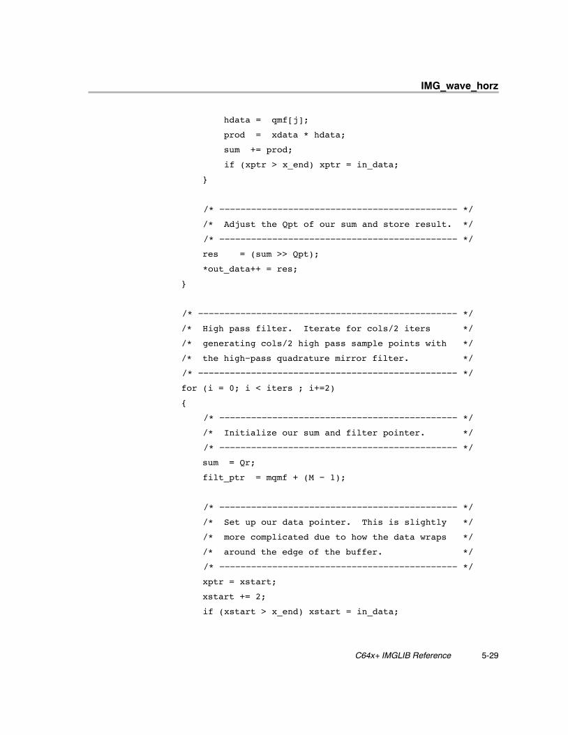
IMG_wave_horz
5-29 C64x+ IMGLIB Reference
hdata = qmf[j];
prod = xdata * hdata;
sum += prod;
if (xptr > x_end) xptr = in_data;
}
/* −−−−−−−−−−−−−−−−−−−−−−−−−−−−−−−−−−−−−−−−−−−−− */
/* Adjust the Qpt of our sum and store result. */
/* −−−−−−−−−−−−−−−−−−−−−−−−−−−−−−−−−−−−−−−−−−−−− */
res = (sum >> Qpt);
*out_data++ = res;
}
/* −−−−−−−−−−−−−−−−−−−−−−−−−−−−−−−−−−−−−−−−−−−−−−−−− */
/* High pass filter. Iterate for cols/2 iters */
/* generating cols/2 high pass sample points with */
/* the high−pass quadrature mirror filter. */
/* −−−−−−−−−−−−−−−−−−−−−−−−−−−−−−−−−−−−−−−−−−−−−−−−− */
for (i = 0; i < iters ; i+=2)
{
/* −−−−−−−−−−−−−−−−−−−−−−−−−−−−−−−−−−−−−−−−−−−−− */
/* Initialize our sum and filter pointer. */
/* −−−−−−−−−−−−−−−−−−−−−−−−−−−−−−−−−−−−−−−−−−−−− */
sum = Qr;
filt_ptr = mqmf + (M − 1);
/* −−−−−−−−−−−−−−−−−−−−−−−−−−−−−−−−−−−−−−−−−−−−− */
/* Set up our data pointer. This is slightly */
/* more complicated due to how the data wraps */
/* around the edge of the buffer. */
/* −−−−−−−−−−−−−−−−−−−−−−−−−−−−−−−−−−−−−−−−−−−−− */
xptr = xstart;
xstart += 2;
if (xstart > x_end) xstart = in_data;
IMG_wave_horz
5-30
/* −−−−−−−−−−−−−−−−−−−−−−−−−−−−−−−−−−−−−−−−−−−−− */
/* Iterate over the taps in our QMF. */
/* −−−−−−−−−−−−−−−−−−−−−−−−−−−−−−−−−−−−−−−−−−−−− */
for ( j = 0; j < M; j++)
{
xdata = *xptr++;
hdata = *filt_ptr−−;
prod = xdata * hdata;
if (xptr > x_end) xptr = in_data;
sum += prod;
}
/* −−−−−−−−−−−−−−−−−−−−−−−−−−−−−−−−−−−−−−−−−−−−− */
/* Adjust the Qpt of our sum and store result. */
/* −−−−−−−−−−−−−−−−−−−−−−−−−−−−−−−−−−−−−−−−−−−−− */
res = (sum >> Qpt);
*out_data++ = res;
}
}
Special Requirements
� This function assumes that the number of taps for the qmf and mqmf filtersis 8, and that the filter coefficient arrays qmf[ ] and mqmf[ ] are double-wordaligned.
� The array in_data[ ] is assumed to be word aligned.
� This function assumes that filter coefficients are maintained as 16-bit Q.15numbers.
� It is also assumed that input data is an array of shorts, to allow for re-useof this function to perform Multi Resolution Analysis where the output ofthis code is feedback as input to an identical next stage.
� The transform is a dyadic wavelet, requiring the number of image columnscols to be a multiple of 2. Cols must also be at least 8.
IMG_wave_horz
5-31 C64x+ IMGLIB Reference
Implementation Notes
� Bank Conflicts: The code has no bank conflicts.
� Endian: The code is ENDIAN NEUTRAL.
� Interruptibility: The code is interrupt–tolerant, but not interruptible.
� Optimizing the code includes issuing one set of reads to the data array andperforming low-pass and high pass filtering together to maximize thenumber of multiplies. The last six elements of the low-pass filter and thefirst six elements of the high-pass filter use the same input. This is usedto appropriately change the output pointer to the low-pass filter after sixiterations. However, for the first six iterations, pointer wraparound canoccur, creating a dependency. Prereading those six values outside thearray prevents the checks that introduce this dependency. In addition, theinput data is read as word wide quantities and the low-pass and high-passfilter coefficients are stored in registers, allowing for the input loop to becompletely unrolled. Therefore, the assembly code has only one loop. Apredication register is used to reset the low-pass output pointer after threeiterations. The merging of the loops allows for the maximum number ofmultiplies with the minimum number of reads.
� This code can implement the Daubechies D4 filter bank for analysis withfour vanishing moments. The length of the analyzing low-pass andhigh-pass filters is 8, in this case.
Benchmarks
Cycles 2 * cols + 25
For cols = 256, cycles = 537For cols = 512, cycles = 1049
Code size 360 bytes
IMG_wave_vert
5-32
Vertical Wavelet TransformIMG_wave_vert
void IMG_wave_vert (const short * restrict * restrict in_data, const short *restrict qmf, const short * restrict mqmf, short * restrict out_ldata, short * restrictout_hdata, int cols)
Arguments
*in_data[8] Pointer to an array of 8 pointers that point to input data linebuffers. Each of the 8 lines has cols number of elementsand must be double-word aligned.
qmf[8] Pointer to Q.15 QMF filter bank for low-pass filtering. Mustbe word aligned.
mqmf[8] Pointer to Q.15 mirror QMF filter bank for high-passfiltering. Must be word aligned.
out_ldata[ ] Pointer to one line of low-pass filtered outputs consisting ofcols number of elements. Must be double-word aligned.
out_hdata[ ] Pointer to one line of high-pass filtered outputs consisting ofcols number of elements. Must be double-word aligned.
cols Width of each line in the input buffer. Must be a multiple of 2.
Description This routine performs the vertical pass of a 2-D wavelet transform. A verticalfilter is applied on 8 lines that are pointed to by the pointers contained in thearray in_data[ ]. Instead of transposing the input image and re-using thehorizontal wavelet function, the vertical filter is applied directly to the imagedata as-is, producing a single line of high-pass and a single line of low-passfiltered outputs. The vertical filter is traversed over the entire width of the line.
In a traditional wavelet implementation, the input context for the low-pass filteris offset by a number of lines from the input context for the high-pass filter fora given pair of output lines. The amount of offset is determined by the numberof filter taps and is generally num_taps − 2 rows (this implementation is fixedat 8 taps, so the offset would be 6 rows).
This implementation breaks from the traditional model so that it can re-use thesame input context for both low-pass and high-pass filters simultaneously. Theresult is that the low-pass and high-pass outputs must instead be offset by thecalling function. To write the low-pass filtered output to the top half and the highpass-filtered output to the bottom half of the output image, the respective startpointers have to be set to:
out_lstart = o_im + ((rows >> 1) − 3) * colsout_hstart = o_im + (rows >> 1) * cols
IMG_wave_vert
5-33 C64x+ IMGLIB Reference
Where o_im is the start of the output image, rows is the number of rows of theinput image, and cols is the number of cols of the output image. The followingtable illustrates how the pointers out_ldata and out_hdata need to be updatedat the start of each call to this function:
Call Number out_ldata out_hdata
1 out_lstart out_hstart
2 out_lstart + cols out_hstart + cols
3 out_lstart + 2 * cols out_hstart + 2 * cols
At this point out_ldata wraps around to become o_im, while out_hdataproceeds as usual:
4 o_im out_hstart + 3 * cols
Corresponding to the output pointer update scheme described above, theinput buffer lines have to be filled starting with the 6th row from the bottom ofthe input image. That is, for the first call of the wave_vert function, the eightinput line buffers consist of the last six plus the first two lines of the image. Forthe second call, the input line buffers contain the last four plus the first 4 linesof the image, and so on.
The routine can obtain maximum performance by using a working buffer of teninput lines to effectively mix processing and data transfer through DMAs. Atthe start of the routine, eight input lines are loaded into the first 8 line buffersand processing begins. In the background, the next two lines are fetched. Thepointers are moved up by 2, namely ptr[i] = ptr[i+2] and the last two lines nowpoint to lines 9 and 10 and processing starts again. In the background, the nexttwo lines are loaded into the first two lines of the line buffer. Pointers move upagain by two but now the last two point to line 0 and 1. This pattern thenrepeats.
IMG_wave_vert
5-34
Algorithm Behavioral C code for the routine wave_vert is provided below:
void IMG_wave_vert
(
short **in_data, /* Array of row pointers */
short *lp_filt, /* Low pass QMF filter */
short *hp_filt, /* High pass QMF filter */
short *out_ldata, /* Low pass output data */
short *out_hdata, /* High pass output data */
int cols /* Length of rows to process */
)
{
int i, j;
/* −−−−−−−−−−−−−−−−−−−−−−−−−−−−−−−−−−−−−−−−−−−−−−−−−−−−−−−−−−−−−−−−−−−− */
/* First, perform the low−pass filter on the eight input rows. */
/* −−−−−−−−−−−−−−−−−−−−−−−−−−−−−−−−−−−−−−−−−−−−−−−−−−−−−−−−−−−−−−−−−−−− */
for (i = 0; i < cols; i++)
{
int sum = 1 << 14;
for (j = 0; j < 8; j++)
sum += in_data[j][i] * lp_filt[j];
out_ldata[i] = sum >> 15;
}
/* −−−−−−−−−−−−−−−−−−−−−−−−−−−−−−−−−−−−−−−−−−−−−−−−−−−−−−−−−−−−−−−−−−−− */
/* Next, perform the high−pass filter on the same eight input rows. */
/* −−−−−−−−−−−−−−−−−−−−−−−−−−−−−−−−−−−−−−−−−−−−−−−−−−−−−−−−−−−−−−−−−−−− */
for (i = 0; i < cols; i++)
{
int sum = 1 << 14;
for (j = 0; j < 8; j++)
sum += in_data[j][i] * hp_filt[7 − j];
out_hdata[i] = sum >> 15;
}
}
IMG_wave_vert
5-35 C64x+ IMGLIB Reference
Special Requirements
� Since the wavelet transform is dyadic, cols must be a multiple of 2.
� The filters qmf[ ] and mqmf[ ] are assumed to be word aligned and have8 taps.
� The input data on any line, and the output arrays out_ldata[ ] and out_hdata[ ] must be double-word aligned.
� The mqmf filter is constructed from the qmf as follows:
status = −1;
for (i = 0; i < M; i++)
{
status = status * −1;
hdata = qmf[i] * status;
filter[i] = hdata;
}
Implementation Notes
� Bank Conflicts: No bank conflicts occur.
� Endian: The code is LITTLE ENDIAN.
� Interruptibility: The code is interrupt-tolerant, but not interruptible.
� The low-pass and high-pass filtering are performed together. This impliesthat the low-pass and high-pass filters be overlapped in execution so thatthe input data array may be read once and both filters can be executed inparallel.
� The inner loop that advances along each filter tap is totally optimized byunrolling. Double-word loads are performed, and paired multiplies areused to perform four iterations of low-pass filter in parallel.
� For the high-pass kernel, the same loop is reused, to save code size. Thisis done by loading the filter coefficients in a special order.
Benchmarks
Cycles 4 * cols + 96
For cols = 256, cycles = 1120For cols = 512, cycles = 2144
Code size 888 bytes
IMG_boundary
5-36
5.2 Image Analysis
Boundary Structural OperatorIMG_boundary
void IMG_boundary(const unsigned char * restrict in_data, int rows, int cols,int * restrict out_coord, int * restrict out_gray)
Arguments
in_data[ ] Input image of size rows * cols. Must be word aligned.
rows Number of input rows.
cols Number of input columns. Must be multiple of 4.
out_coord[ ] Output array of packed coordinates. Must be wordaligned.
out_gray[ ] Output array of corresponding gray levels. Must be wordaligned.
Description This routine scans an image for non-zero pixels. The locations of those pixelsare stored to the array out_coord[ ] as packed Y/X pairs, with Y in the upperhalf, and X in the lower half. The gray levels of those pixels are stored in theout_gray[ ] array.
Algorithm Behavioral C code for the routine is provided below:
void IMG_boundary(
const unsigned char in_data,
int rows, int cols,
int out_coord,
int out_gray)
{
int x, y, p;
for (y = 0; y < rows; y++) for (x = 0; x < cols; x++)
if ((p = in_data[x + y*cols] != 0)
{
*out_coord++ = ((y & 0xFFFF) << 16) | (x & 0xFFFF); *out_gray++ = p;
}
}
IMG_boundary
5-37 C64x+ IMGLIB Reference
Special Requirements
� Array in_data[ ] must be word aligned.
� cols must be a multiple of 4.
� At least one row is being processed.
� Output buffers out_coord and out_gray should start in different banks andmust be word aligned.
� No more than 32764 rows or 32764 columns are being processed.
Implementation Notes
� Bank Conflicts: No bank conflicts occur as long as out_coord andout_gray start in different banks. If they start in the same bank, everyaccess to each array will cause a bank conflict.
� Endian: The code is LITTLE ENDIAN.
� Interruptibility: The code is interrupt-tolerant but not interruptible.
� Outer and inner loops are collapsed together.
� Inner loop is unrolled to process four pixels per iteration.
Benchmarks
Cycles 1.25 * (cols * rows) + 12
For cols = 128, rows = 3, cycles = 492For cols = 720, rows = 8, cycles = 7212
Code size 132 bytes
IMG_dilate_bin
5-38
3x3 Binary DilationIMG_dilate_bin
void IMG_dilate_bin(const unsigned char * restrict in_data, unsigned char *restrict out_data, const char * restrict mask, int cols)
Arguments
in_data[ ] Binary input image (8 pixels per byte).
out_data[ ] Filtered binary output image.
mask[3][3] 3x3 filter mask.
cols Number of columns / 8. cols must be a multiple of 8.
Description This routine dilate_bin() implements 3x3 binary dilation. The input imageconsists of binary valued pixels (0s or 1s). The dilation operator generatesoutput pixels by ORing the pixels under the input mask together to generatethe output pixel. The input mask specifies whether one or more pixels from theinput are to be ignored.
Algorithm The routine computes output for a target pixel as follows:
result = 0;
if (mask[0][0] != DONT_CARE) result |= input[y + 0][x + 0];
if (mask[0][1] != DONT_CARE) result |= input[y + 1][x + 1];
if (mask[0][2] != DONT_CARE) result |= input[y + 2][x + 2];
if (mask[1][0] != DONT_CARE) result |= input[y + 0][x + 0];
if (mask[1][1] != DONT_CARE) result |= input[y + 1][x + 1];
if (mask[1][2] != DONT_CARE) result |= input[y + 2][x + 2];
if (mask[2][0] != DONT_CARE) result |= input[y + 0][x + 0];
if (mask[2][1] != DONT_CARE) result |= input[y + 1][x + 1];
if (mask[2][2] != DONT_CARE) result |= input[y + 2][x + 2];
output[y][x] = result;
For this code, “DONT_CARE” is specified by a negative value in the inputmask. Non-negative values in the mask cause the corresponding pixel to beincluded in the dilation operation.
Special Requirements
� Pixels are organized within each byte such that the pixel with the smallestindex is in the LSB position, and the pixel with the largest index is in theMSB position. (That is, the code assumes a LITTLE ENDIAN bit ordering.)
� Negative values in the mask specify “DONT_CARE”, and non-negativevalues specify that pixels are included in the dilation operation.
� The input image needs to have a multiple of 64 pixels (bits) per row.Therefore, cols must be a multiple of 8.
IMG_dilate_bin
5-39 C64x+ IMGLIB Reference
Implementation Notes
� Bank Conflicts: No bank conflicts occur in this function.
� Endian: The code is LITTLE ENDIAN.
� Interruptibility: The code is fully interruptible.
� The 3x3 dilation mask is applied to 32 output pixels simultaneously. Thisis done with 32-bit-wide bit-wise operators in the register file. To do this,the code reads in a 34-bit-wide input window, and 40-bit operations areused to manipulate the pixels initially. Because the code reads a 34-bitcontext for each 32-bits of output, the input needs to be one byte longerthan the output to make the rightmost two pixels well-defined.
Benchmarks
Cycles 7 * cols/8 + 25
For cols = 128, cycles = 137For cols = 720, cycles = 655
Code size 324 bytes
IMG_erode_bin
5-40
3x3 Binary ErosionIMG_erode_bin
void IMG_erode_bin(const unsigned char * restrict in_data, unsigned char *restrict out_data, const char * restrict mask, int cols)
Arguments
in_data[ ] Binary input image (8 pixels per byte).
out_data[ ] Filtered binary output image.
mask[3][3] 3x3 filter mask.
cols Number of columns / 8. cols must be a multiple of 8.
Description This routine implements 3x3 binary erosion. The input image consists of binaryvalued pixels (0s or 1s). The erosion operator generates output pixels byANDing the pixels under the input mask together to generate the output pixel.The input mask specifies whether one or more pixels from the input are to beignored.
Algorithm The routine computes output for a target pixel as follows:
result = 1;
if (mask[0][0] != DONT_CARE) result &= input[y + 0][x + 0];
if (mask[0][1] != DONT_CARE) result &= input[y + 1][x + 1];
if (mask[0][2] != DONT_CARE) result &= input[y + 2][x + 2];
if (mask[1][0] != DONT_CARE) result &= input[y + 0][x + 0];
if (mask[1][1] != DONT_CARE) result &= input[y + 1][x + 1];
if (mask[1][2] != DONT_CARE) result &= input[y + 2][x + 2];
if (mask[2][0] != DONT_CARE) result &= input[y + 0][x + 0];
if (mask[2][1] != DONT_CARE) result &= input[y + 1][x + 1];
if (mask[2][2] != DONT_CARE) result &= input[y + 2][x + 2];
output[y][x] = result;
For this code, “DONT_CARE” is specified by a negative value in the inputmask. Non-negative values in the mask cause the corresponding pixel to beincluded in the erosion operation.
Special Requirements
� Pixels are organized within each byte such that the pixel with the smallestindex is in the LSB position, and the pixel with the largest index is in theMSB position. (That is, the code assumes a LITTLE ENDIAN bit ordering.)
� Negative values in the mask specify “DONT_CARE”, and non-negativevalues specify that pixels are included in the erosion operation.
� The input image needs to have a multiple of 64 pixels (bits) per row.Therefore, cols must be a multiple of 8.

IMG_erode_bin
5-41 C64x+ IMGLIB Reference
Implementation Notes
� Bank Conflicts: No bank conflicts occur in this function.
� Endian: The code is LITTLE ENDIAN.
� Interruptibility: The code is fully interruptible.
� The 3x3 erosion mask is applied to 32 output pixels simultaneously. Thisis done with 32-bit-wide bit-wise operators in the register file. To do this,the code reads in a 34-bit-wide input window, and 40-bit operations areused to manipulate the pixels initially. Because the code reads a 34-bitcontext for each 32-bits of output, the input needs to be one byte longerthan the output to make the rightmost two pixels well-defined.
Benchmarks
Cycles 7 * cols/8 + 25
For cols = 128, cycles = 137For cols = 720, cycles = 655
Code size 324 bytes
IMG_histogram
5-42
Histogram ComputationIMG_histogram
void IMG_histogram (const unsigned char * restrict in_data, int n, shortaccumulate, unsigned short * restrict t_hist, unsigned short * restrict hist)
Arguments
in_data[n] Input image. Must be word aligned.
n Number of pixels in input image. Must be multiple of 8.
accumulate 1: Add to existing histogram in hist[ ]
−1: Subtract from existing histogram in hist[ ]
t_hist[1024] Array of temporary histogram bins. Must be initialized tozero.
hist[256] Array of updated histogram bins.
Description This routine computes the histogram of the array in_data[ ] which contains n8-bit elements. It returns a histogram in the array hist[ ] with 256 bins at 16-bitprecision. It can either add or subtract to an existing histogram, using theaccumulate control. It requires temporary storage for four temporaryhistograms, t_hist[ ], which are later summed together.
Algorithm Behavioral C code for the function is provided below:
void IMG_histogram (unsigned char *in_data, int n, intaccumulate, unsigned short *t_hist, unsigned short * hist)
{
int pixel, j;
for (j = 0; j < n; j++)
{
pixel = (int) in_data[j];
hist[pixel] += accumulate;
}
}
Special Requirements
� The temporary array of data, t_hist[ ], must be initialized to zero.
� The input array of data, in_data[ ], must be word-aligned.
� n must be a multiple of 8.
� The maximum number of pixels that can be profiled in each bin is 65535in the main histogram.
IMG_histogram
5-43 C64x+ IMGLIB Reference
Implementation Notes
� This code operates on four interleaved histogram bins. The loop is dividedinto two halves. The even half operates on even words full of pixels andthe odd half operates on odd words. Each half processes 4 pixels at a time,and both halves operate on the same four sets of histogram bins. Thisintroduces a memory dependency on the histogram bins which ordinarilywould degrade performance. To break the memory dependencies, the twohalves forward their results to each other via the register file, bypassingmemory. Exact memory access ordering obviates the need to predicatestores.
� The algorithm is ordered as follows:
1) Load from histogram for even half.
2) Store odd_bin to histogram for odd half (previous iteration).
3) If data_even = previous data_odd, increment even_bin by 2, elseincrement even_bin by 1, forward to odd.
4) Load from histogram for odd half (current iteration).
5) Store even_bin to histogram for even half.
6) If data_odd = previous data_even increment odd_bin by 2, elseincrement odd_bin by 1, forward to even.
7) Go to 1.
� With this particular ordering, forwarding is necessary between even/oddhalves when pixels in adjacent halves need to be placed in the same bin.The store is never predicated and occurs speculatively as it will beoverwritten by the next value containing the extra forwarded value.
� The four histograms are interleaved with each bin spaced four half-wordsapart and each histogram starting in a different memory bank. This allowsthe four histogram accesses to proceed in any order without worryingabout bank conflicts. The diagram below illustrates this (addresses arehalf-word offsets):
0 1 2 3 4 5 …
hst0 hst1 hst2 hst3 hst0 hst1 …
bin0 bin0 bin0 bin0 bin1 bin1 …
hst0,…,hst3 are the four histograms and bin0, bin1,… are the bins used.These are then summed together at the end in blocks of 4.
IMG_histogram
5-44
� Bank Conflicts: No bank conflicts occur in this function.� Endian: The code is LITTLE ENDIAN.� Interruptibility: The code is interrupt-tolerant, but not interruptible.
Benchmarks
Cycles 9/8 * n + 228
For n = 512, cycles = 804For n = 1024, cycles = 1380
Code size 552 bytes
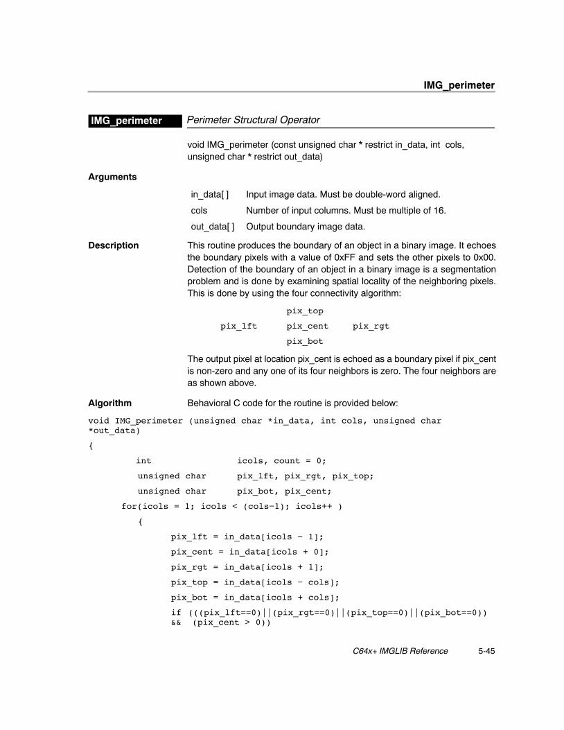
IMG_perimeter
5-45 C64x+ IMGLIB Reference
Perimeter Structural OperatorIMG_perimeter
void IMG_perimeter (const unsigned char * restrict in_data, int cols, unsigned char * restrict out_data)
Arguments
in_data[ ] Input image data. Must be double-word aligned.
cols Number of input columns. Must be multiple of 16.
out_data[ ] Output boundary image data.
Description This routine produces the boundary of an object in a binary image. It echoesthe boundary pixels with a value of 0xFF and sets the other pixels to 0x00.Detection of the boundary of an object in a binary image is a segmentationproblem and is done by examining spatial locality of the neighboring pixels.This is done by using the four connectivity algorithm:
pix_top
pix_lft pix_cent pix_rgt
pix_bot
The output pixel at location pix_cent is echoed as a boundary pixel if pix_centis non-zero and any one of its four neighbors is zero. The four neighbors areas shown above.
Algorithm Behavioral C code for the routine is provided below:
void IMG_perimeter (unsigned char *in_data, int cols, unsigned char*out_data)
{
int icols, count = 0;
unsigned char pix_lft, pix_rgt, pix_top;
unsigned char pix_bot, pix_cent;
for(icols = 1; icols < (cols−1); icols++ )
{
pix_lft = in_data[icols − 1];
pix_cent = in_data[icols + 0];
pix_rgt = in_data[icols + 1];
pix_top = in_data[icols − cols];
pix_bot = in_data[icols + cols];
if (((pix_lft==0)||(pix_rgt==0)||(pix_top==0)||(pix_bot==0)) && (pix_cent > 0))
IMG_perimeter
5-46
{
out_data[icols] = pix_cent;
count++;
}
else
{
out_data[icols] = 0;
}
}
return(count);
}
Special Requirements
� Array in_data[ ] must be double-word aligned.
� cols must be a multiple of 16.
� This code expects three input lines each of width cols pixels and producesone output line of width (cols – 1) pixels.
Implementation Notes
� Double word wide loads are used to bring in pixels from three consecutivelines.
� The instructions CMPEQ4/CMPGTU4 are used to compare if pixels aregreater than or equal to zero. Comparison results are re-used betweenadjacent comparisons.
� Multiplies replace some of the conditional operations to reduce thebottleneck on the predication registers as well as on the .L, .S, and .D units.
� XPND4 and BITC4 are used to perform expansion and bit count.
� The loop is unrolled once and computes 16 output pixels per iteration.
� Bank Conflicts: No bank conflicts occur.
� Endian: This code is LITTLE ENDIAN.
� Interruptibility: The code is interrupt–tolerant but not interruptible.
Benchmarks
Cycles 10 * cols/16 + 55
For cols = 128, cycles = 135
For cols = 720, cycles = 505
Code size 600 bytes
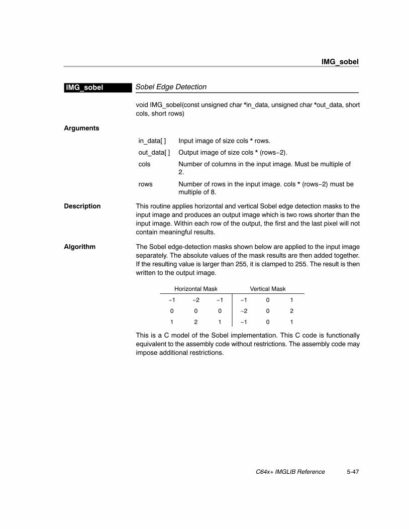
IMG_sobel
5-47 C64x+ IMGLIB Reference
Sobel Edge DetectionIMG_sobel
void IMG_sobel(const unsigned char *in_data, unsigned char *out_data, shortcols, short rows)
Arguments
in_data[ ] Input image of size cols * rows.
out_data[ ] Output image of size cols * (rows−2).
cols Number of columns in the input image. Must be multiple of2.
rows Number of rows in the input image. cols * (rows−2) must bemultiple of 8.
Description This routine applies horizontal and vertical Sobel edge detection masks to theinput image and produces an output image which is two rows shorter than theinput image. Within each row of the output, the first and the last pixel will notcontain meaningful results.
Algorithm The Sobel edge-detection masks shown below are applied to the input imageseparately. The absolute values of the mask results are then added together.If the resulting value is larger than 255, it is clamped to 255. The result is thenwritten to the output image.
Horizontal Mask Vertical Mask
−1 −2 −1 −1 0 1
0 0 0 −2 0 2
1 2 1 −1 0 1
This is a C model of the Sobel implementation. This C code is functionallyequivalent to the assembly code without restrictions. The assembly code mayimpose additional restrictions.
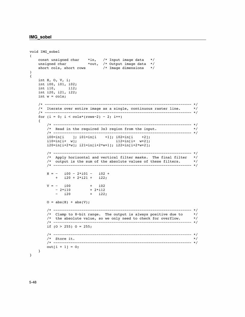
IMG_sobel
5-48
void IMG_sobel( const unsigned char *in, /* Input image data */ unsigned char *out, /* Output image data */ short cols, short rows /* Image dimensions */){ int H, O, V, i; int i00, i01, i02; int i10, i12; int i20, i21, i22; int w = cols;
/* −−−−−−−−−−−−−−−−−−−−−−−−−−−−−−−−−−−−−−−−−−−−−−−−−−−−−−−−−−−−−−−−−−−− */ /* Iterate over entire image as a single, continuous raster line. */ /* −−−−−−−−−−−−−−−−−−−−−−−−−−−−−−−−−−−−−−−−−−−−−−−−−−−−−−−−−−−−−−−−−−−− */ for (i = 0; i < cols*(rows−2) − 2; i++) { /* −−−−−−−−−−−−−−−−−−−−−−−−−−−−−−−−−−−−−−−−−−−−−−−−−−−−−−−−−−−−−−−− */ /* Read in the required 3x3 region from the input. */ /* −−−−−−−−−−−−−−−−−−−−−−−−−−−−−−−−−−−−−−−−−−−−−−−−−−−−−−−−−−−−−−−− */ i00=in[i ]; i01=in[i +1]; i02=in[i +2]; i10=in[i+ w]; i12=in[i+ w+2]; i20=in[i+2*w]; i21=in[i+2*w+1]; i22=in[i+2*w+2];
/* −−−−−−−−−−−−−−−−−−−−−−−−−−−−−−−−−−−−−−−−−−−−−−−−−−−−−−−−−−−−−−−− */ /* Apply horizontal and vertical filter masks. The final filter */ /* output is the sum of the absolute values of these filters. */ /* −−−−−−−−−−−−−−−−−−−−−−−−−−−−−−−−−−−−−−−−−−−−−−−−−−−−−−−−−−−−−−−− */
H = − i00 − 2*i01 − i02 + + i20 + 2*i21 + i22;
V = − i00 + i02 − 2*i10 + 2*i12 − i20 + i22;
O = abs(H) + abs(V);
/* −−−−−−−−−−−−−−−−−−−−−−−−−−−−−−−−−−−−−−−−−−−−−−−−−−−−−−−−−−−−−−−− */ /* Clamp to 8−bit range. The output is always positive due to */ /* the absolute value, so we only need to check for overflow. */ /* −−−−−−−−−−−−−−−−−−−−−−−−−−−−−−−−−−−−−−−−−−−−−−−−−−−−−−−−−−−−−−−− */ if (O > 255) O = 255;
/* −−−−−−−−−−−−−−−−−−−−−−−−−−−−−−−−−−−−−−−−−−−−−−−−−−−−−−−−−−−−−−−− */ /* Store it. */ /* −−−−−−−−−−−−−−−−−−−−−−−−−−−−−−−−−−−−−−−−−−−−−−−−−−−−−−−−−−−−−−−− */ out[i + 1] = O; }}

IMG_sobel
5-49 C64x+ IMGLIB Reference
Special Requirements
� cols must be a multiple of 2.
� At least eight output pixels must be processed; i.e., cols * (rows−2) mustbe a multiple of 8.
Implementation Notes
� Bank Conflicts: No bank conflicts occur.
� Endian: The code is LITTLE ENDIAN.
� Interruptibility: The code is interrupt-tolerant, but not interruptible.
� The values of the left-most and right-most pixels on each line of the outputare not computed.
� Eight output pixels are computed per iteration using loop unrolling andpacked operations.
� The last stage of the epilog is kept to accommodate for the exception ofstoring only 6 outputs in the last iteration.
Benchmarks
Cycles 11 * cols * (rows – 2)/8 + 23
For cols = 128, rows = 8, cycles = 1079For cols = 720, rows = 8, cycles = 5963
Code size 688 bytes
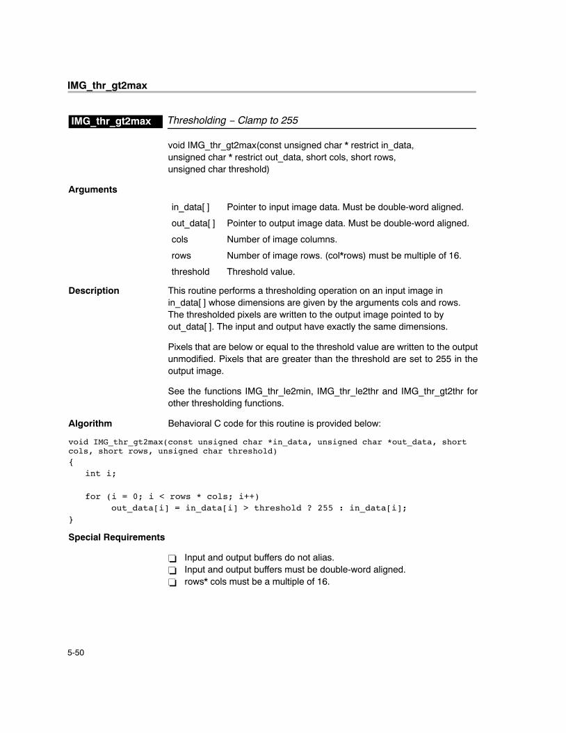
IMG_thr_gt2max
5-50
Thresholding − Clamp to 255IMG_thr_gt2max
void IMG_thr_gt2max(const unsigned char * restrict in_data, unsigned char * restrict out_data, short cols, short rows, unsigned char threshold)
Arguments
in_data[ ] Pointer to input image data. Must be double-word aligned.
out_data[ ] Pointer to output image data. Must be double-word aligned.
cols Number of image columns.
rows Number of image rows. (col*rows) must be multiple of 16.
threshold Threshold value.
Description This routine performs a thresholding operation on an input image in in_data[ ] whose dimensions are given by the arguments cols and rows. The thresholded pixels are written to the output image pointed to by out_data[ ]. The input and output have exactly the same dimensions.
Pixels that are below or equal to the threshold value are written to the outputunmodified. Pixels that are greater than the threshold are set to 255 in theoutput image.
See the functions IMG_thr_le2min, IMG_thr_le2thr and IMG_thr_gt2thr forother thresholding functions.
Algorithm Behavioral C code for this routine is provided below:
void IMG_thr_gt2max(const unsigned char *in_data, unsigned char *out_data, shortcols, short rows, unsigned char threshold){ int i; for (i = 0; i < rows * cols; i++) out_data[i] = in_data[i] > threshold ? 255 : in_data[i];}
Special Requirements
� Input and output buffers do not alias.� Input and output buffers must be double-word aligned.� rows* cols must be a multiple of 16.
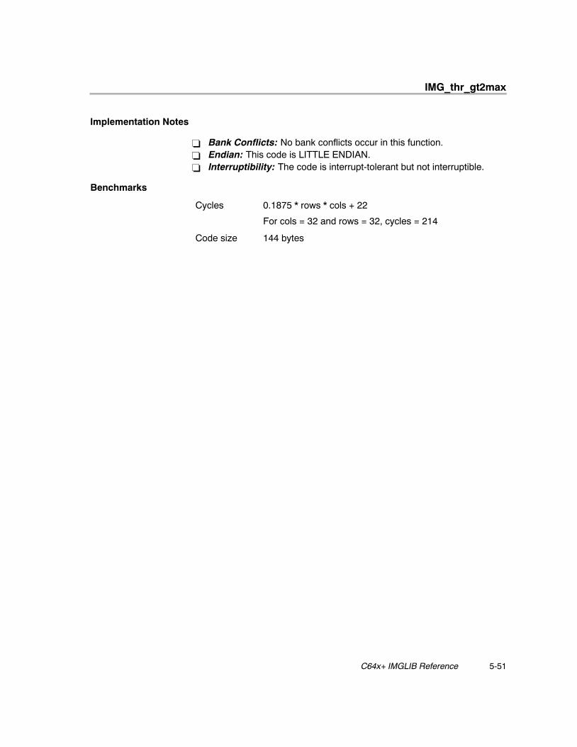
IMG_thr_gt2max
5-51 C64x+ IMGLIB Reference
Implementation Notes
� Bank Conflicts: No bank conflicts occur in this function.� Endian: This code is LITTLE ENDIAN.� Interruptibility: The code is interrupt-tolerant but not interruptible.
Benchmarks
Cycles 0.1875 * rows * cols + 22
For cols = 32 and rows = 32, cycles = 214
Code size 144 bytes
IMG_thr_gt2thr
5-52
Thresholding − Clip Above ThresholdIMG_thr_gt2thr
void IMG_thr_gt2thr(const unsigned char * restrict in_data, unsigned char * restrict out_data, short cols, short rows, unsigned char threshold)
Arguments
in_data[ ] Pointer to input image data. Must be double-word aligned.
out_data[ ] Pointer to output image data. Must be double-word aligned.
cols Number of image columns.
rows Number of image rows. (cols*rows) must be multiple of 16.
threshold Threshold value.
Description This routine performs a thresholding operation on an input image in in_data[ ] whose dimensions are given by the arguments cols and rows. The thresholded pixels are written to the output image pointed to by out_data[ ]. The input and output have exactly the same dimensions.
Pixels that are below or equal to the threshold value are written to the outputunmodified. Pixels that are greater than the threshold are set to the thresholdvalue in the output image.
See the functions IMG_thr_le2min, IMG_thr_le2thr and IMG_thr_gt2max forother thresholding functions.
Algorithm Behavioral C code for this routine is provided below:
void IMG_thr_gt2thr(const unsigned char *in_data, unsigned char *out_data, shortcols, short rows, unsigned char threshold){ int i; for (i = 0; i < rows * cols; i++) out_data[i] = in_data[i] > threshold ? thr : in_data[i];}
Special Requirements
� Input and output buffers do not alias.� Input and output buffers must be double-word aligned.� rows* cols must be a multiple of 16.
IMG_thr_gt2thr
5-53 C64x+ IMGLIB Reference
Implementation Notes
� Bank Conflicts: No bank conflicts occur in this function.� Endian: This code is ENDIAN NEUTRAL.� Interruptibility: The code is interrupt-tolerant but not interruptible.
Benchmarks
Cycles 0.125 * rows * cols + 20
For rows = 32 and cols = 32, cycles = 148
Code size 108 bytes
IMG_thr_le2min
5-54
Thresholding − Clamp to zeroIMG_thr_le2min
void IMG_thr_le2min(const unsigned char * restrict in_data, unsigned char * restrict out_data, short cols, short rows, unsigned char threshold)
Arguments
in_data[ ] Pointer to input image data. Must be double-word aligned.
out_data[ ] Pointer to output image data. Must be double-word aligned.
cols Number of image columns.
rows Number of image rows. cols*rows must be multiple of 16.
threshold Threshold value.
Description This routine performs a thresholding operation on an input image in in_data[ ] whose dimensions are given by the arguments cols and rows. The thresholded pixels are written to the output image pointed to by out_data[ ]. The input and output have exactly the same dimensions.
Pixels that are above the threshold value are written to the output unmodified.Pixels that are less than or equal to the threshold are set to zero in the outputimage.
See the functions IMG_thr_gt2thr, IMG_thr_le2thr and IMG_thr_gt2max forother thresholding functions.
Algorithm Behavioral C code for this routine is provided below:
void IMG_thr_le2min(const unsigned char *in_data, unsigned char *out_data, shortcols, short rows, unsigned char threshold){ int i; for (i = 0; i < rows * cols; i++) out_data[i] = in_data[i] <= threshold ? 0 : in_data[i];}
Special Requirements
� Input and output buffers do not alias.� Input and output buffers must be double-word aligned.� rows* cols must be a multiple of 16.
IMG_thr_le2min
5-55 C64x+ IMGLIB Reference
Implementation Notes
� Bank Conflicts: No bank conflicts occur in this function.� Endian: This code is ENDIAN NEUTRAL.� Interruptibility: The code is interrupt-tolerant but not interruptible.
Benchmarks
Cycles 0.1875 * rows * cols + 22
For rows = 32 and cols = 32, cycles = 214
Code size 144 bytes
IMG_thr_le2thr
5-56
Thresholding − Clip Below ThresholdIMG_thr_le2thr
void IMG_thr_le2thr(const unsigned char * restrict in_data, unsigned char * restrict out_data, short cols, short rows, unsigned char threshold)
Arguments
in_data[ ] Pointer to input image data. Must be double-word aligned.
out_data[ ] Pointer to output image data. Must be double-word aligned.
cols Number of image columns.
rows Number of image rows. cols*rows must be multiple of 16.
threshold Threshold value.
Description This routine performs a thresholding operation on an input image in in_data[ ] whose dimensions are given by the arguments cols and rows. The thresholded pixels are written to the output image pointed to by out_data[ ]. The input and output have exactly the same dimensions.
Pixels that are above the threshold value are written to the output unmodified.Pixels that are less than or equal to the threshold are set to the threshold valuein the output image.
See the functions IMG_thr_gt2thr, IMG_thr_le2min and IMG_thr_gt2max forother thresholding functions.
Algorithm Behavioral C code for this routine is provided below:
void IMG_thr_le2thr(const unsigned char *in_data, unsigned char *out_data, short cols, short rows, unsigned char threshold){ int i; for (i = 0; i < rows * cols; i++) out_data[i] = in_data[i] <= threshold ? threshold : in_data[i];}
Special Requirements
� Input and output buffers do not alias.� Input and output buffers must be double-word aligned.� rows* cols must be a multiple of 16.
IMG_thr_le2thr
5-57 C64x+ IMGLIB Reference
Implementation Notes
� Bank Conflicts: No bank conflicts occur in this function.
� Endian: This code is ENDIAN NEUTRAL.
� Interruptibility: The code is interrupt-tolerant but not interruptible.
� The loop is unrolled 16x. Packed-data processing techniques allow theparallel processing of all 16 pixels.
Benchmarks
Cycles 0.125 *cols * rows + 20
For rows = 32, cols = 32, cycles = 148
Code size 108 bytes
IMG_conv_3x3
5-58
5.3 Picture Filtering/Format Conversions
3x3 ConvolutionIMG_conv_3x3
void IMG_conv_3x3(const unsigned char * restrict in_data, unsigned char * restrict out_data, int cols, const char * restrict mask, int shift)
Arguments
in_data[ ] Input image.
out_data[ ] Output image.
cols Number of columns in the input image. Must be multiple of8.
mask[3][3] 3x3 mask.
shift Shift value.
Description The convolution kernel accepts three rows of cols input pixels and producesone output row of cols pixels using the input mask of 3 by 3. The user-definedshift value is used to shift the convolution value down to the byte range. Theconvolution sum is also range limited to 0.255. The shift amount is non-zero forlow pass filters, and zero for high pass and sharpening filters.
Algorithm This is the C equivalent of the assembly code without restrictions. The assem-bly code is hand optimized and restrictions apply as noted.
void IMG_conv_3x3(unsigned char *in_data, unsigned char *out_data, int cols, char*mask, int shift)
{
unsigned char *IN1,*IN2,*IN3;
unsigned char *OUT;
short pix10, pix20, pix30;
short mask10, mask20, mask30;
int sum, sum00, sum11;
int i;
int sum22, j;
IN1 = in_data;
IMG_conv_3x3
5-59 C64x+ IMGLIB Reference
IN2 = IN1 + x_dim;
IN3 = IN2 + x_dim;
OUT = out_data;
for (j = 0; j < cols; j++)
{
sum = 0;
for (i = 0; i < 3; i++)
{
pix10 = IN1[i];
pix20 = IN2[i];
pix30 = IN3[i];
mask10 = mask[i];
mask20 = mask[i + 3];
mask30 = mask[i + 6];
sum00 = pix10 * mask10;
sum11 = pix20 * mask20;
sum22 = pix30 * mask30;
sum += sum00 + sum11+ sum22;
}
IN1++;
IN2++;
IN3++;
sum = (sum >> shift);
if ( sum < 0 ) sum = 0;
if ( sum > 255 ) sum = 255;
*OUT++ = sum;
}
}
IMG_conv_3x3
5-60
Special Requirements
� cols output pixels are produced when three lines, each with a width of colspixels, are given as input.
� cols must be a multiple of 8.
� The array pointed to by out_data should not alias with the array pointedto by in_data.
� The mask to the kernel should be such that the sum for each pixel is lessthan or equal to 65536. This restriction arises because of the use of theADD2 instruction to compute two pixels in a register.
Implementation Notes
� Bank Conflicts: No bank conflicts occur in this function.
� Endian: The code is LITTLE ENDIAN.
� Interruptibility: The code is fully interruptible.
� This code is designed to take advantage of the 8-bit multiplier capabilityprovided by MPYSU4/MPYUS4. The kernel uses loop unrolling andcomputes eight output pixels for every iteration.
� The eight bit elements in each mask are replicated four times to fill a wordby using the PACKL4 and PACK2 instructions.
� The image data is brought in using LDNDW. The results of themultiplications are summed using ADD2. The output values are packedusing SPACK2 and stored using STNDW, which writes eight 8-bit valuesat a time.
Benchmarks
Cycles For cols <=32, cycles = 68
For cols> 32, cycles = 9 * cols/8 + 33
Code size 510 bytes
IMG_corr_3x3
5-61 C64x+ IMGLIB Reference
3x3 CorrelationIMG_corr_3x3
void IMG_corr_3x3(const unsigned char * restrict in_data, int * restrictout_data, const unsigned char mask[3][3], int x_dim, int n_out)
Arguments
in_data[ ] Pointer to input array of 8-bit pixels.
out_data[ ] Pointer to output array of 32-bit values.
mask[3][3] Pointer to 8-bit mask.
x_dim Width of image.
n_out Number of outputs. Must be multiple of 8.
Description This routine performs a point-by-point multiplication of the 3x3 mask with theinput image. The results of the nine multiplications are then summed toproduce a 32-bit sum. The sum is stored in an output array. The image maskto be correlated is typically part of the input image or another image. The maskis moved one column at a time, advancing the mask over the portion of the rowspecified by n_out. When n_out is larger than x_dim, multiple rows will beprocessed.
In an application, the correlation kernel is called once for every row as shownbelow:
for (i = 0; i < rows; i++)
{
IMG_corr_3x3(&i_data[i * x_dim],
&o_data[i*n_out], mask, x_dim, n_out);
}
Alternately, the kernel may be invoked for multiple rows at a time, although thetwo outputs at the end of each row will have meaningless values. For example:
IMG_corr_3x3(i_data, o_data, mask, x_dim, 2 * x_dim);
This will produce two rows of outputs into o_data. The outputs at locationso_data[x_dim − 2], o_data[x_dim − 1], o_data[2*x_dim − 2] ando_data[2*x_dim − 1] will have meaningless values. This is harmless, althoughthe application will have to account for this when interpreting the results.
IMG_corr_3x3
5-62
Algorithm Behavioral C code is provided below:
void IMG_corr_3x3
(
const unsigned char *i_data, /* input image */
int *restrict o_data, /* output image */
const unsigned char mask[3][3], /* convolution mask */
int x_dim, /* width of image */
int n_out /* number of outputs */
)
{
int i, j, k;
for (i = 0; i < n_out; i++)
{
int sum = 0;
for (j = 0; j < 3; j++)
for (k = 0; k < 3; k++)
sum += i_data[j * x_dim + i + k] * mask[j][k];
o_data[i] = sum;
}
}
Special Requirements
� The array pointed to by out_data must not alias with the array pointed toby in_data or mask.
� The number of outputs n_out must be a multiple of 8. In cases where n_outis not a multiple of 8, most applications can safely round n_out up to thenext multiple of 8 and ignore the extra outputs. This kernel does not roundn_out up for the user.
IMG_corr_3x3
5-63 C64x+ IMGLIB Reference
Implementation Notes
� Bank Conflicts: No bank conflicts occur.
� Endian: The code is LITTLE ENDIAN.
� Interruptibility: The code is fully interruptible.
� The inner loops are unrolled completely. The outer loop is unrolled 8 times.
� 3 DOTPU4s are used to calculate the 3 rows of each output pixel. The 3DOTPU4s are then accumulated to a 32-bit result and stored out. (Notethat only 3 of every 4 8-bit MPYs in the DOTPU4 are actually used. Thefourth MPY is unused.)
� Using non-aligned loads and stores avoids alignment issues.
Benchmarks
Cycles 1.5 * n_out + 22
For n_out = 248, cycles = 394
Code size 296 bytes
IMG_corr_gen
5-64
Generalized CorrelationIMG_corr_gen
void IMG_corr_gen(const short *in_data, short *h, short *out_data, int M, intcols)
Arguments
in_data[ ] Input image data (one line of width cols). Must be word aligned.
h[M] 1xM tap filter.
out_data[ ] Output array of size cols – M + 8. Must be double-word aligned.
M Number of filter taps.
cols Width of line of image data.
Description This routine performs a generalized correlation with a 1xM tap filter. It can becalled repetitively to form an arbitrary MxN 2-D generalized correlationfunction. The correlation sums are stored as half words. The input pixel, andmask data are assumed to be shorts. No restrictions are placed on the numberof columns in the image (cols) or the number of filter taps (M).
Algorithm Behavioral C code for the routine is provided below:
void IMG_corr_gen_cn
(
const short *in_data,
const short *h,
short *out_data,
int M,
int cols
)
{
int i, j;
for (j = 0; j < cols − M; j++)
for (i = 0; i < M; i++)
out_data[j] += in_data[i + j] * h[i];
}
IMG_corr_gen
5-65 C64x+ IMGLIB Reference
Special Requirements
� Array in_data[ ] must be word aligned, array out_data[ ] must bedouble-word aligned, and array h[ ] must be half-word aligned.
� The size of the output array must be at least (cols − m + 8).
Implementation Notes
� Bank Conflicts: No bank conflicts occur.
� Endian: The code is ENDIAN NEUTRAL.
� Interruptibility: The code is interrupt-tolerant, but not interruptible.
� Since this function performs generalized correlation, the number of filtertaps can be as small as one. Hence, it is not beneficial to pipeline this loopin its original form. In addition, collapsing of the loops causes datadependencies and degrades the performance.
� However, loop order interchange can be used effectively. For example, theouter loop of the natural C code is exchanged to be the inner loop that isto be software pipelined in the optimized assembly code. It is beneficial topipeline this loop because typical image dimensions are larger than thenumber of filter taps. Note however, that the number of data loads andstores increase within this loop compared to the natural C code.
� Unrolling of the outer loop assumes that there are an even number of filtertaps (M). Two special cases arise:
� m = 1. In this case, a separate version that processes just 1 tap is usedand the code directly starts from this loop without executing theversion of the code for even number of taps.
� m is odd. In this case, the even version of the loop is used for as manyeven taps as possible and then the last tap is computed using the oddtap special version created for m = 1.
� The inner loop is unrolled 8 times, assuming that the loop iteration(cols – M) is a multiple of 8. In most typical images, cols is a multiple of 8but since M is completely general, (cols – M) may not be a multiple of 8.If (cols – M) is not a multiple of 8, then the inner loop iterates fewer timesthan required and certain output pixels may not be computed. Use thefollowing process to solve this problem:
� Eight is added to (cols – M) so that the next higher multiple of 8 iscomputed. This implies that in certain cases, up to 8 extra pixels maybe computed. To annul this extra computation, 8 locations starting atout_data[cols−M] are zeroed out before returning to the callingfunction.
IMG_corr_gen
5-66
Benchmarks
Cycles (case 1 – evennumber of filter taps)
M * [floor[(cols − M + 8)/4] + 11] + 38
For M = 8, cols = 720, cycles = 1566
Cycles (case 2 – odd num-ber of filter taps)
(M − 1) * [floor[(cols − E + 8)/4] + 11] + 3 * floor[(cols − E + 4)/4] + 48,
where E = M + 1
For M = 9, cols = 720, cycles = 2102
Code size 604 bytes
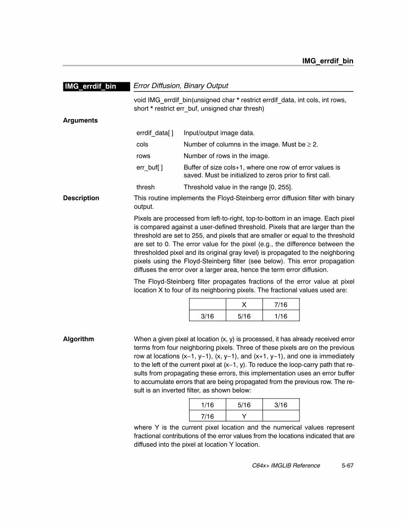
IMG_errdif_bin
5-67 C64x+ IMGLIB Reference
Error Diffusion, Binary OutputIMG_errdif_bin
void IMG_errdif_bin(unsigned char * restrict errdif_data, int cols, int rows, short * restrict err_buf, unsigned char thresh)
Arguments
errdif_data[ ] Input/output image data.
cols Number of columns in the image. Must be ≥ 2.
rows Number of rows in the image.
err_buf[ ] Buffer of size cols+1, where one row of error values issaved. Must be initialized to zeros prior to first call.
thresh Threshold value in the range [0, 255].
Description This routine implements the Floyd-Steinberg error diffusion filter with binaryoutput.
Pixels are processed from left-to-right, top-to-bottom in an image. Each pixelis compared against a user-defined threshold. Pixels that are larger than thethreshold are set to 255, and pixels that are smaller or equal to the thresholdare set to 0. The error value for the pixel (e.g., the difference between thethresholded pixel and its original gray level) is propagated to the neighboringpixels using the Floyd-Steinberg filter (see below). This error propagationdiffuses the error over a larger area, hence the term error diffusion.
The Floyd-Steinberg filter propagates fractions of the error value at pixellocation X to four of its neighboring pixels. The fractional values used are:
X 7/16
3/16 5/16 1/16
Algorithm When a given pixel at location (x, y) is processed, it has already received errorterms from four neighboring pixels. Three of these pixels are on the previousrow at locations (x−1, y−1), (x, y−1), and (x+1, y−1), and one is immediatelyto the left of the current pixel at (x−1, y). To reduce the loop-carry path that re-sults from propagating these errors, this implementation uses an error bufferto accumulate errors that are being propagated from the previous row. The re-sult is an inverted filter, as shown below:
1/16 5/16 3/16
7/16 Y
where Y is the current pixel location and the numerical values representfractional contributions of the error values from the locations indicated that arediffused into the pixel at location Y location.
IMG_errdif_bin
5-68
This modified operation requires the first row of pixels to be processedseparately, since this row has no error inputs from the previous row. Theprevious row’s error contributions in this case are essentially zero. One wayto achieve this is with a special loop that avoids the extra calculation involvedwith injecting the previous row’s errors. Another is to pre-zero the error bufferbefore processing the first row. This function supports the latter approach.
Behavioral C code for the routine is provided below:
void IMG_errdif_bin
(
unsigned char *errdif_data, /* Input/Output image ptr */
int cols, /* Number of columns (Width) */
int rows, /* Number of rows (Height) */
short err_buf, /* row−to−row error buffer. */
unsigned char thresh /* Threshold from [0x00, 0xFF] */
)
{
int x, i, y; /* Loop counters */
int F; /* Current pixel value at [x,y] */
int errA; /* Error value at [x−1, y−1] */
int errB; /* Error value at [ x, y−1] */
int errC; /* Error value at [x+1, y−1] */
int errE; /* Error value at [x−1, y] */
int errF; /* Error value at [ x, y] */
/* −−−−−−−−−−−−−−−−−−−−−−−−−−−−−−−−−−−−−−−−−−−−−−−−−−−−−−−−− */
/* Step through rows of pixels. */
/* −−−−−−−−−−−−−−−−−−−−−−−−−−−−−−−−−−−−−−−−−−−−−−−−−−−−−−−−− */
for (y = 0, i = 0; y < rows; y++)
{
/* −−−−−−−−−−−−−−−−−−−−−−−−−−−−−−−−−−−−−−−−−−−−−−−−−−−−−− */
/* Start off with our initial errors set to zero at */
/* the start of the line since we do not have any */
/* pixels to the left of the row. These error terms */
/* are maintained within the inner loop. */
/* −−−−−−−−−−−−−−−−−−−−−−−−−−−−−−−−−−−−−−−−−−−−−−−−−−−−−− */
errA = 0; errE = 0;
IMG_errdif_bin
5-69 C64x+ IMGLIB Reference
errB = err_buf[0];
/* −−−−−−−−−−−−−−−−−−−−−−−−−−−−−−−−−−−−−−−−−−−−−−−−−−−−−− */
/* Step through pixels in each row. */
/* −−−−−−−−−−−−−−−−−−−−−−−−−−−−−−−−−−−−−−−−−−−−−−−−−−−−−− */
for (x = 0; x < cols; x++, i++)
{
/* −−−−−−−−−−−−−−−−−−−−−−−−−−−−−−−−−−−−−−−−−−−−−−−−−−− */
/* Load the error being propagated from pixel ’C’ */
/* from our error buffer. This was calculated */
/* during the previous line. */
/* −−−−−−−−−−−−−−−−−−−−−−−−−−−−−−−−−−−−−−−−−−−−−−−−−−− */
errC = err_buf[x+1];
/* −−−−−−−−−−−−−−−−−−−−−−−−−−−−−−−−−−−−−−−−−−−−−−−−−−− */
/* Load our pixel value to quantize. */
/* −−−−−−−−−−−−−−−−−−−−−−−−−−−−−−−−−−−−−−−−−−−−−−−−−−− */
F = errdif_data[i];
/* −−−−−−−−−−−−−−−−−−−−−−−−−−−−−−−−−−−−−−−−−−−−−−−−−−− */
/* Calculate our resulting pixel. If we assume */
/* that this pixel will be set to zero, this also */
/* doubles as our error term. */
/* −−−−−−−−−−−−−−−−−−−−−−−−−−−−−−−−−−−−−−−−−−−−−−−−−−− */
errF = F + ((errE*7 + errA + errB*5 + errC*3) >> 4);
/* −−−−−−−−−−−−−−−−−−−−−−−−−−−−−−−−−−−−−−−−−−−−−−−−−−− */
/* Set pixels that are larger than the threshold to */
/* 255, and pixels that are smaller than the */
/* threshold to 0. */
/* −−−−−−−−−−−−−−−−−−−−−−−−−−−−−−−−−−−−−−−−−−−−−−−−−−− */
if (errF > thresh) errdif_data[i] = 0xFF;
else errdif_data[i] = 0;
/* −−−−−−−−−−−−−−−−−−−−−−−−−−−−−−−−−−−−−−−−−−−−−−−−−−− */
/* If the pixel was larger than the threshold, then */
IMG_errdif_bin
5-70
/* we need subtract 255 from our error. In any */
/* case, store the error to the error buffer. */
/* −−−−−−−−−−−−−−−−−−−−−−−−−−−−−−−−−−−−−−−−−−−−−−−−−−− */
if (errF > thresh) err_buf[x] = errF = errF − 0xFF;
else err_buf[x] = errF;
/* −−−−−−−−−−−−−−−−−−−−−−−−−−−−−−−−−−−−−−−−−−−−−−−−−−− */
/* Propagate error terms for the next pixel. */
/* −−−−−−−−−−−−−−−−−−−−−−−−−−−−−−−−−−−−−−−−−−−−−−−−−−− */
errE = errF;
errA = errB;
errB = errC;
}
}
}
Special Requirements
� The number of columns must be at least 2.
� err_buf[ ] must be initialized to zeros for the first call and the returnederr_buf [ ] should be provided for the next call.
� errdif_data[ ] is used for both input and output.
� The size of err_buf[ ] should be cols+1.
Implementation Notes
� Bank Conflicts: No bank conflicts occur.
� Endian: The code is ENDIAN NEUTRAL.
� Interruptibility: This function is interruptible. Maximum interrupt delay is4*cols + 9 cycles.
� The outer loop has been interleaved with the prolog and epilog of the innerloop.
� Constants 7, 5, 3, 1 for filter-tap multiplications are shifted left 12 to avoidSHR 4 operation in the critical path.
� The inner loop is software-pipelined.
Benchmarks
Cycles (4*cols + 11)*rows + 7
For cols = 128, rows = 128, cycles = 66,951For cols = 720, rows = 480, cycles = 1,387,687
Code size 296 bytes
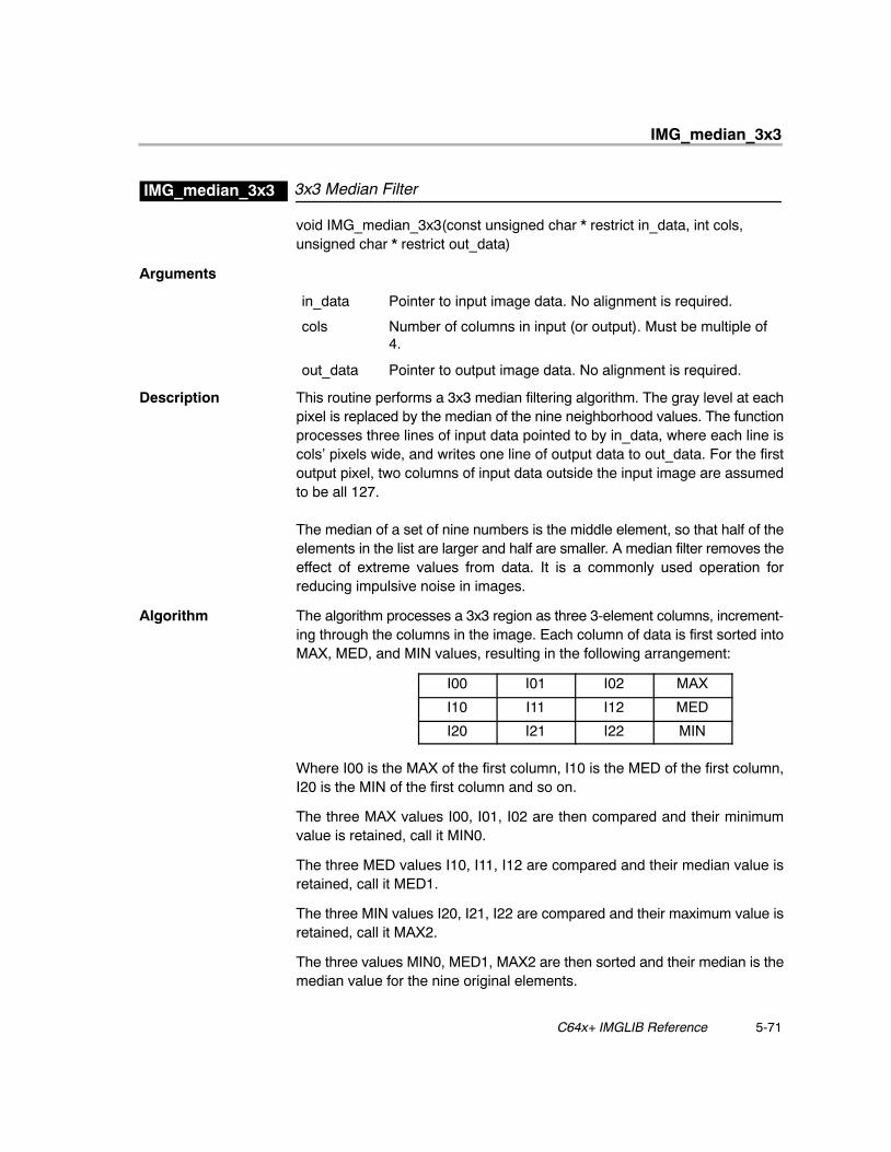
IMG_median_3x3
5-71 C64x+ IMGLIB Reference
3x3 Median FilterIMG_median_3x3
void IMG_median_3x3(const unsigned char * restrict in_data, int cols, unsigned char * restrict out_data)
Arguments
in_data Pointer to input image data. No alignment is required.
cols Number of columns in input (or output). Must be multiple of4.
out_data Pointer to output image data. No alignment is required.
Description This routine performs a 3x3 median filtering algorithm. The gray level at eachpixel is replaced by the median of the nine neighborhood values. The functionprocesses three lines of input data pointed to by in_data, where each line iscols’ pixels wide, and writes one line of output data to out_data. For the firstoutput pixel, two columns of input data outside the input image are assumedto be all 127.
The median of a set of nine numbers is the middle element, so that half of theelements in the list are larger and half are smaller. A median filter removes theeffect of extreme values from data. It is a commonly used operation forreducing impulsive noise in images.
Algorithm The algorithm processes a 3x3 region as three 3-element columns, increment-ing through the columns in the image. Each column of data is first sorted intoMAX, MED, and MIN values, resulting in the following arrangement:
I00 I01 I02 MAX
I10 I11 I12 MED
I20 I21 I22 MIN
Where I00 is the MAX of the first column, I10 is the MED of the first column,I20 is the MIN of the first column and so on.
The three MAX values I00, I01, I02 are then compared and their minimumvalue is retained, call it MIN0.
The three MED values I10, I11, I12 are compared and their median value isretained, call it MED1.
The three MIN values I20, I21, I22 are compared and their maximum value isretained, call it MAX2.
The three values MIN0, MED1, MAX2 are then sorted and their median is themedian value for the nine original elements.
IMG_median_3x3
5-72
After this output is produced, a new set of column data is read in, say I03, I13,I23. This data is sorted as a column and processed along with I01, I11, I21, andI02, I12, I22 as explained above. Since these two sets of data are alreadysorted, they can be re-used as is.
Special Requirements
� cols must be a multiple of 4.� No alignment is required.
Implementation Notes
� Bank Conflicts: No bank conflicts occur.� Endian: The code is LITTLE ENDIAN.� Interruptibility:The code is fully interruptible.
Benchmarks
Cycles For cols = 4, cycles = 49
For cols = 8, cycles = 53
For cols > 8m, cycles = 2 * cols + 31
Code size 232 bytes
IMG_pix_expand
5-73 C64x+ IMGLIB Reference
Pixel ExpandIMG_pix_expand
void IMG_pix_expand(int n, const unsigned char * restrict in_data, short *restrict out_data)
Arguments
n Number of samples to process. Must be multiple of16.
in_data Pointer to input array (unsigned chars). Must bedouble-word aligned.
out_data Pointer to output array (shorts). Must be double-word aligned.
Description This routine takes an array of unsigned chars (8-bit pixels), and zero-extendsthem to signed 16-bit values (shorts).
Algorithm Behavioral C code for the routine is provided below:
void IMG_pix_expand (int n, unsigned char *in_data, short*out_data)
{
int j;
for (j = 0; j < n; j++)
out_data[j] = (short) in_data[j];
}
Special Requirements
� in_data and out_data must be double-word aligned.� n must be a multiple of 16.
Implementation Notes
� Bank Conflicts: No bank conflicts occur.
� Endian: The code is LITTLE ENDIAN.
� Interruptibility: The code is interrupt-tolerant, but not interruptible
� The loop is unrolled 16 times, loading bytes with LDDW. It uses UNPKHU4and UNPKLU4 to unpack the data and store the results with STDW.
Benchmarks
Cycles cycles = 3 * n/16 + 15
For n = 1072, cycles = 216
Code size 108 bytes

IMG_pix_expand_nM32
5-74
Pixel Expand (n≥32)IMG_pix_expand_nM32
void IMG_pix_expand_nM32(int n, const unsigned char * restrict in_data,short * restrict out_data)
Arguments
n Number of samples to process. Must be multiple of 16.Mustbe ≥ 32.
in_data Pointer to input array (unsigned chars). Must be double-word aligned.
out_data Pointer to output array (shorts). Must be double-wordaligned.
Description This routine takes an array of unsigned chars (8-bit pixels), and zero-extendsthem to signed 16-bit values (shorts).
Algorithm Behavioral C code for the routine is provided below:
void IMG_pix_expand (int n, unsigned char *in_data, short*out_data)
{
int j;
for (j = 0; j < n; j++)
out_data[j] = (short) in_data[j];
}
Special Requirements
� in_data and out_data must be double-word aligned.� n must be a multiple of 16.Must be ≥ 32.
Implementation Notes
� Bank Conflicts: No bank conflicts occur.
� Endian: The code is LITTLE ENDIAN.
� Interruptibility: The code is fully interruptible.
� The loop is unrolled 16 times, loading bytes with LDDW. It uses UNPKHU4and UNPKLU4 to unpack the data and store the results with STDW.
Benchmarks
Cycles For n<= 48, cycles = 19
For n > 48, cycles = 3 * n/16 + 10
Code size 92 bytes
IMG_pix_sat
5-75 C64x+ IMGLIB Reference
Pixel SaturateIMG_pix_sat
void IMG_pix_sat(int n, const short * restrict in_data, unsigned char * restrictout_data)
Arguments
n Number of samples to process. Must be multiple of 32.
in_data Pointer to input data (shorts).
out_data Pointer to output data (unsigned chars).
Description This routine performs the saturation of 16-bit signed numbers to 8-bit unsignednumbers. If the data is over 255, it is clamped to 255. If it is less than 0, it isclamped to 0.
Algorithm Behavioral C code for the routine is provided below:
void IMG_pix_sat_cn
(
int n,
const short in_data,
unsigned char out_data
)
{
int i, pixel;
for (i = 0; i < n; i++)
{
pixel = in_data[i];
if (pixel > 0xFF)
{
out_data[i] = 0xFF;
} else if (pixel < 0x00)
{
out_data[i] = 0x00;
} else
{
out_data[i] = pixel;
}
}
}
IMG_pix_sat
5-76
Special Requirements
� The input size n must be a multiple of 32. The code behaves correctly ifn is zero.
Special Requirements
� Bank Conflicts: No bank conflicts occur.
� Endian: The code is LITTLE ENDIAN.
� Interruptibility: The code is fully interruptible.
� The inner loop has been unrolled to fill a 6 cycle loop. This allows the codeto be interruptible.
� The prolog and epilog have been collapsed into the kernel.
Benchmarks
Cycles For n<= 64, cycles = 21
For n>64, cycles = 3 * n/16 + 7
Code size 124 bytes
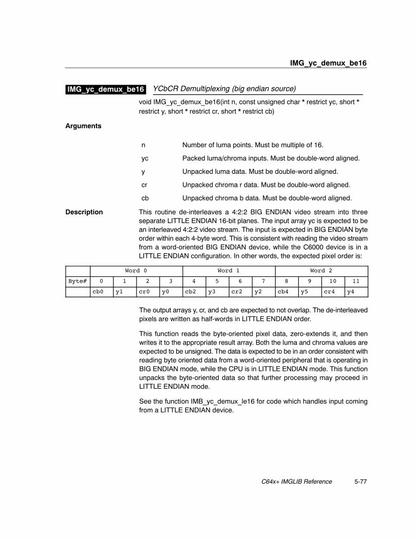
IMG_yc_demux_be16
5-77 C64x+ IMGLIB Reference
YCbCR Demultiplexing (big endian source)IMG_yc_demux_be16
void IMG_yc_demux_be16(int n, const unsigned char * restrict yc, short *restrict y, short * restrict cr, short * restrict cb)
Arguments
n Number of luma points. Must be multiple of 16.
yc Packed luma/chroma inputs. Must be double-word aligned.
y Unpacked luma data. Must be double-word aligned.
cr Unpacked chroma r data. Must be double-word aligned.
cb Unpacked chroma b data. Must be double-word aligned.
Description This routine de-interleaves a 4:2:2 BIG ENDIAN video stream into threeseparate LITTLE ENDIAN 16-bit planes. The input array yc is expected to bean interleaved 4:2:2 video stream. The input is expected in BIG ENDIAN byteorder within each 4-byte word. This is consistent with reading the video streamfrom a word-oriented BIG ENDIAN device, while the C6000 device is in aLITTLE ENDIAN configuration. In other words, the expected pixel order is:
Word 0 Word 1 Word 2
Byte# 0 1 2 3 4 5 6 7 8 9 10 11
cb0 y1 cr0 y0 cb2 y3 cr2 y2 cb4 y5 cr4 y4
The output arrays y, cr, and cb are expected to not overlap. The de-interleavedpixels are written as half-words in LITTLE ENDIAN order.
This function reads the byte-oriented pixel data, zero-extends it, and thenwrites it to the appropriate result array. Both the luma and chroma values areexpected to be unsigned. The data is expected to be in an order consistent withreading byte oriented data from a word-oriented peripheral that is operating inBIG ENDIAN mode, while the CPU is in LITTLE ENDIAN mode. This functionunpacks the byte-oriented data so that further processing may proceed inLITTLE ENDIAN mode.
See the function IMB_yc_demux_le16 for code which handles input comingfrom a LITTLE ENDIAN device.

IMG_yc_demux_be16
5-78
Algorithm Behavioral C code for the routine is provided below:
void yc_demux_be16(int n, unsigned char *yc, short *y,
short *cr, short *cb )
{
int i;
for (i = 0; i < (n >> 1); i++)
{
y[2*i+0] = yc[4*i + 3];
y[2*i+1] = yc[4*i + 1];
cr[i] = yc[4*i + 2];
cb[i] = yc[4*i + 0];
}
}
Special Requirements
� The input and output data must be aligned to double-word boundaries.� n must be a multiple of 16.
Implementation Notes
� Bank Conflicts: No bank conflicts occur.
� Endian: The code is LITTLE ENDIAN.
� Interruptibility: This code is fully interruptible.
� The loop has been unrolled a total of 16 times to allow for processing 8pixels in each datapath.
� Double-word-wide loads and stores maximize memory bandwidthutilization.
� This code uses _gmpy4() to ease the L/S/D unit bottleneck on ANDs. The_gmpy4(value, 0x00010001) is equivalent to value & 0x00FF00FF, aslong as the size field of GFPGFR is equal to 7. (The polynomial does notmatter.)
Benchmarks
Cycles 3 * n/8 + 18
For n = 1024: 402 cycles
Code size 316 bytes
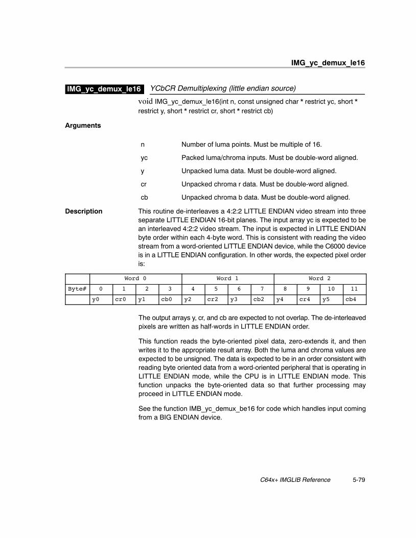
IMG_yc_demux_le16
5-79 C64x+ IMGLIB Reference
YCbCR Demultiplexing (little endian source)IMG_yc_demux_le16
void IMG_yc_demux_le16(int n, const unsigned char * restrict yc, short *restrict y, short * restrict cr, short * restrict cb)
Arguments
n Number of luma points. Must be multiple of 16.
yc Packed luma/chroma inputs. Must be double-word aligned.
y Unpacked luma data. Must be double-word aligned.
cr Unpacked chroma r data. Must be double-word aligned.
cb Unpacked chroma b data. Must be double-word aligned.
Description This routine de-interleaves a 4:2:2 LITTLE ENDIAN video stream into threeseparate LITTLE ENDIAN 16-bit planes. The input array yc is expected to bean interleaved 4:2:2 video stream. The input is expected in LITTLE ENDIANbyte order within each 4-byte word. This is consistent with reading the videostream from a word-oriented LITTLE ENDIAN device, while the C6000 deviceis in a LITTLE ENDIAN configuration. In other words, the expected pixel orderis:
Word 0 Word 1 Word 2
Byte# 0 1 2 3 4 5 6 7 8 9 10 11
y0 cr0 y1 cb0 y2 cr2 y3 cb2 y4 cr4 y5 cb4
The output arrays y, cr, and cb are expected to not overlap. The de-interleavedpixels are written as half-words in LITTLE ENDIAN order.
This function reads the byte-oriented pixel data, zero-extends it, and thenwrites it to the appropriate result array. Both the luma and chroma values areexpected to be unsigned. The data is expected to be in an order consistent withreading byte oriented data from a word-oriented peripheral that is operating inLITTLE ENDIAN mode, while the CPU is in LITTLE ENDIAN mode. Thisfunction unpacks the byte-oriented data so that further processing mayproceed in LITTLE ENDIAN mode.
See the function IMB_yc_demux_be16 for code which handles input comingfrom a BIG ENDIAN device.
IMG_yc_demux_le16
5-80
Algorithm Behavioral C code for the routine is provided below:
void IMG_yc_demux_le16(int n, unsigned char *yc, short *y,
short *cr, short *cb )
{
int i;
for (i = 0; i < (n >> 1); i++)
{
y[2*i+0] = yc[4*i + 0];
y[2*i+1] = yc[4*i + 2];
cr[i] = yc[4*i + 1];
cb[i] = yc[4*i + 3];
}
}
Special Requirements
� The input and output data must be aligned to double-word boundaries.� n must be a multiple of 16.
Implementation Notes
� Bank Conflicts: No bank conflicts occur.
� Endian: The code is LITTLE ENDIAN.
� Interruptibility: This code is fully interruptible.
� The loop has been unrolled a total of 16 times to allow for processing 8pixels in each datapath.
� Double-word-wide loads and stores maximize memory bandwidthutilization.
� This code uses _gmpy4() to ease the L/S/D unit bottleneck on ANDs. The_gmpy4(value, 0x00010001) is equivalent to value & 0x00FF00FF, aslong as the size field of GFPGFR is equal to 7. (The polynomial does notmatter.)
Benchmarks
Cycles 3 * n/8 + 18
For n = 1024: 402 cycles
Code size 352 bytes
IMG_ycbcr422p_rgb565
5-81 C64x+ IMGLIB Reference
Planarized YCbCR 4:2:2/4:2:0 to RGB 5:6:5 Color SpaceConversion
IMG_ycbcr422p_rgb565
void IMG_ycbcr422p_rgb565(const short * restrict coeff, const unsignedchar * restrict y_data, const unsigned char * restrict cb_data, constunsigned char * restrict cr_data, unsigned short * restrict rgb_data,unsigned num_pixels)
Arguments
coeff[5] Matrix coefficients.
y_data Luminence data (Y’). Must be double-word aligned.
cb_data Blue color−diff (B’−Y’). Must be word aligned.
cr_data Red color−diff (R’−Y’). Must be word aligned.
rgb_data RGB 5:6:5 packed pixel out. Must be double-word aligned.
num_pixels Number of luma pixels to process. Must be multiple of 8.
Description This kernel performs Y’CbCr to RGB conversion. The coeff[] array contains thecolor-space-conversion matrix coefficients. The y_data, cb_data and cr_datapointers point to the separate input image planes. The rgb_data pointer pointsto the output image buffer, and must be word aligned. The kernel is designed toprocess arbitrary amounts of 4:2:2 image data, although 4:2:0 image data maybe processed as well. For 4:2:2 input data, the y_data, cb_data and cr_dataarrays may hold an arbitrary amount of image data. For 4:2:0 input data, only asingle scan-line (or portion thereof) may be processed at a time.
The coefficients in the coeff array must be in signed Q13 form.
This code can perform various flavors of Y’CbCr to RGB conversion, as long asthe offsets on Y, Cb, and Cr are −16, −128, and −128, respectively, and thecoefficients match the pattern shown. The kernel implements the followingmatrix form, which involves 5 unique coefficients:
[ coeff[0] 0.0000 coeff[1] ] [ Y’ − 16 ] [ R’][ coeff[0] coeff[2] coeff[3] ] * [ Cb − 128 ] = [ G’][ coeff[0] coeff[4] 0.0000 ] [ Cr − 128 ] [ B’]
Below are some common coefficient sets, along with the matrix equation thatthey correspond to. Coefficients are in signed Q13 notation, which gives asuitable balance between precision and range.
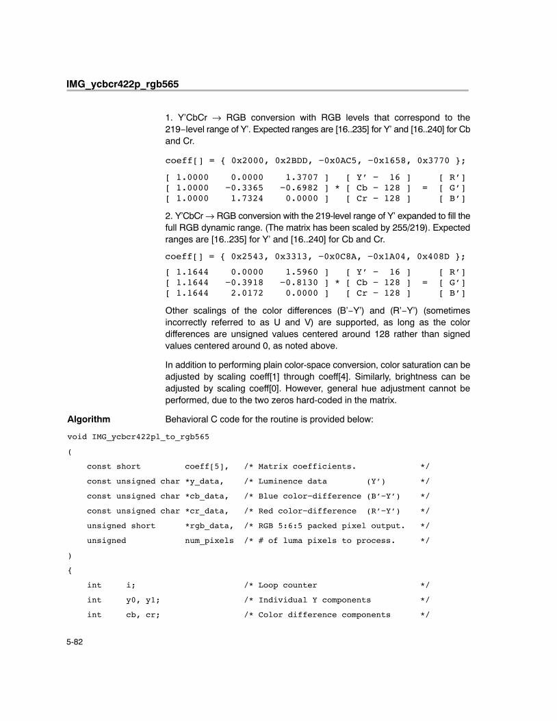
IMG_ycbcr422p_rgb565
5-82
1. Y’CbCr → RGB conversion with RGB levels that correspond to the219−level range of Y’. Expected ranges are [16..235] for Y’ and [16..240] for Cband Cr.
coeff[] = { 0x2000, 0x2BDD, −0x0AC5, −0x1658, 0x3770 };
[ 1.0000 0.0000 1.3707 ] [ Y’ − 16 ] [ R’][ 1.0000 −0.3365 −0.6982 ] * [ Cb − 128 ] = [ G’][ 1.0000 1.7324 0.0000 ] [ Cr − 128 ] [ B’]
2. Y’CbCr → RGB conversion with the 219-level range of Y’ expanded to fill thefull RGB dynamic range. (The matrix has been scaled by 255/219). Expectedranges are [16..235] for Y’ and [16..240] for Cb and Cr.
coeff[] = { 0x2543, 0x3313, −0x0C8A, −0x1A04, 0x408D };
[ 1.1644 0.0000 1.5960 ] [ Y’ − 16 ] [ R’][ 1.1644 −0.3918 −0.8130 ] * [ Cb − 128 ] = [ G’][ 1.1644 2.0172 0.0000 ] [ Cr − 128 ] [ B’]
Other scalings of the color differences (B’−Y’) and (R’−Y’) (sometimesincorrectly referred to as U and V) are supported, as long as the colordifferences are unsigned values centered around 128 rather than signedvalues centered around 0, as noted above.
In addition to performing plain color-space conversion, color saturation can beadjusted by scaling coeff[1] through coeff[4]. Similarly, brightness can beadjusted by scaling coeff[0]. However, general hue adjustment cannot beperformed, due to the two zeros hard-coded in the matrix.
Algorithm Behavioral C code for the routine is provided below:
void IMG_ycbcr422pl_to_rgb565
(
const short coeff[5], /* Matrix coefficients. */
const unsigned char *y_data, /* Luminence data (Y’) */
const unsigned char *cb_data, /* Blue color−difference (B’−Y’) */
const unsigned char *cr_data, /* Red color−difference (R’−Y’) */
unsigned short *rgb_data, /* RGB 5:6:5 packed pixel output. */
unsigned num_pixels /* # of luma pixels to process. */
)
{
int i; /* Loop counter */
int y0, y1; /* Individual Y components */
int cb, cr; /* Color difference components */
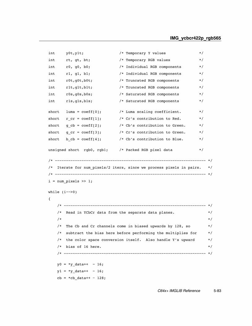
IMG_ycbcr422p_rgb565
5-83 C64x+ IMGLIB Reference
int y0t,y1t; /* Temporary Y values */
int rt, gt, bt; /* Temporary RGB values */
int r0, g0, b0; /* Individual RGB components */
int r1, g1, b1; /* Individual RGB components */
int r0t,g0t,b0t; /* Truncated RGB components */
int r1t,g1t,b1t; /* Truncated RGB components */
int r0s,g0s,b0s; /* Saturated RGB components */
int r1s,g1s,b1s; /* Saturated RGB components */
short luma = coeff[0]; /* Luma scaling coefficient. */
short r_cr = coeff[1]; /* Cr’s contribution to Red. */
short g_cb = coeff[2]; /* Cb’s contribution to Green. */
short g_cr = coeff[3]; /* Cr’s contribution to Green. */
short b_cb = coeff[4]; /* Cb’s contribution to Blue. */
unsigned short rgb0, rgb1; /* Packed RGB pixel data */
/* −−−−−−−−−−−−−−−−−−−−−−−−−−−−−−−−−−−−−−−−−−−−−−−−−−−−−−−−−−−−−−−−−−−− */
/* Iterate for num_pixels/2 iters, since we process pixels in pairs. */
/* −−−−−−−−−−−−−−−−−−−−−−−−−−−−−−−−−−−−−−−−−−−−−−−−−−−−−−−−−−−−−−−−−−−− */
i = num_pixels >> 1;
while (i−−>0)
{
/* −−−−−−−−−−−−−−−−−−−−−−−−−−−−−−−−−−−−−−−−−−−−−−−−−−−−−−−−−−−−−−−− */
/* Read in YCbCr data from the separate data planes. */
/* */
/* The Cb and Cr channels come in biased upwards by 128, so */
/* subtract the bias here before performing the multiplies for */
/* the color space conversion itself. Also handle Y’s upward */
/* bias of 16 here. */
/* −−−−−−−−−−−−−−−−−−−−−−−−−−−−−−−−−−−−−−−−−−−−−−−−−−−−−−−−−−−−−−−− */
y0 = *y_data++ − 16;
y1 = *y_data++ − 16;
cb = *cb_data++ − 128;
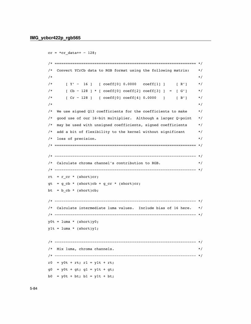
IMG_ycbcr422p_rgb565
5-84
cr = *cr_data++ − 128;
/* ================================================================ */
/* Convert YCrCb data to RGB format using the following matrix: */
/* */
/* [ Y’ − 16 ] [ coeff[0] 0.0000 coeff[1] ] [ R’] */
/* [ Cb − 128 ] * [ coeff[0] coeff[2] coeff[3] ] = [ G’] */
/* [ Cr − 128 ] [ coeff[0] coeff[4] 0.0000 ] [ B’] */
/* */
/* We use signed Q13 coefficients for the coefficients to make */
/* good use of our 16−bit multiplier. Although a larger Q−point */
/* may be used with unsigned coefficients, signed coefficients */
/* add a bit of flexibility to the kernel without significant */
/* loss of precision. */
/* ================================================================ */
/* −−−−−−−−−−−−−−−−−−−−−−−−−−−−−−−−−−−−−−−−−−−−−−−−−−−−−−−−−−−−−−−− */
/* Calculate chroma channel’s contribution to RGB. */
/* −−−−−−−−−−−−−−−−−−−−−−−−−−−−−−−−−−−−−−−−−−−−−−−−−−−−−−−−−−−−−−−− */
rt = r_cr * (short)cr;
gt = g_cb * (short)cb + g_cr * (short)cr;
bt = b_cb * (short)cb;
/* −−−−−−−−−−−−−−−−−−−−−−−−−−−−−−−−−−−−−−−−−−−−−−−−−−−−−−−−−−−−−−−− */
/* Calculate intermediate luma values. Include bias of 16 here. */
/* −−−−−−−−−−−−−−−−−−−−−−−−−−−−−−−−−−−−−−−−−−−−−−−−−−−−−−−−−−−−−−−− */
y0t = luma * (short)y0;
y1t = luma * (short)y1;
/* −−−−−−−−−−−−−−−−−−−−−−−−−−−−−−−−−−−−−−−−−−−−−−−−−−−−−−−−−−−−−−−− */
/* Mix luma, chroma channels. */
/* −−−−−−−−−−−−−−−−−−−−−−−−−−−−−−−−−−−−−−−−−−−−−−−−−−−−−−−−−−−−−−−− */
r0 = y0t + rt; r1 = y1t + rt;
g0 = y0t + gt; g1 = y1t + gt;
b0 = y0t + bt; b1 = y1t + bt;
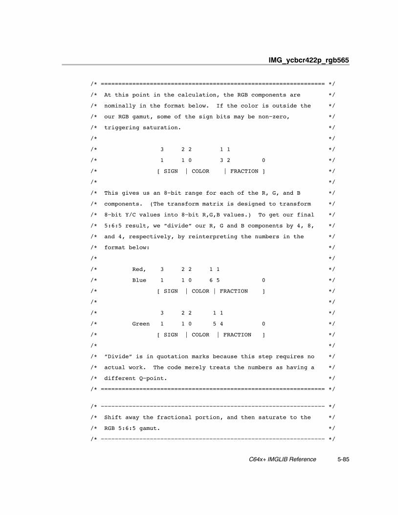
IMG_ycbcr422p_rgb565
5-85 C64x+ IMGLIB Reference
/* ================================================================ */
/* At this point in the calculation, the RGB components are */
/* nominally in the format below. If the color is outside the */
/* our RGB gamut, some of the sign bits may be non−zero, */
/* triggering saturation. */
/* */
/* 3 2 2 1 1 */
/* 1 1 0 3 2 0 */
/* [ SIGN | COLOR | FRACTION ] */
/* */
/* This gives us an 8−bit range for each of the R, G, and B */
/* components. (The transform matrix is designed to transform */
/* 8−bit Y/C values into 8−bit R,G,B values.) To get our final */
/* 5:6:5 result, we ”divide” our R, G and B components by 4, 8, */
/* and 4, respectively, by reinterpreting the numbers in the */
/* format below: */
/* */
/* Red, 3 2 2 1 1 */
/* Blue 1 1 0 6 5 0 */
/* [ SIGN | COLOR | FRACTION ] */
/* */
/* 3 2 2 1 1 */
/* Green 1 1 0 5 4 0 */
/* [ SIGN | COLOR | FRACTION ] */
/* */
/* ”Divide” is in quotation marks because this step requires no */
/* actual work. The code merely treats the numbers as having a */
/* different Q−point. */
/* ================================================================ */
/* −−−−−−−−−−−−−−−−−−−−−−−−−−−−−−−−−−−−−−−−−−−−−−−−−−−−−−−−−−−−−−−− */
/* Shift away the fractional portion, and then saturate to the */
/* RGB 5:6:5 gamut. */
/* −−−−−−−−−−−−−−−−−−−−−−−−−−−−−−−−−−−−−−−−−−−−−−−−−−−−−−−−−−−−−−−− */
IMG_ycbcr422p_rgb565
5-86
r0t = r0 >> 16;
g0t = g0 >> 15;
b0t = b0 >> 16;
r1t = r1 >> 16;
g1t = g1 >> 15;
b1t = b1 >> 16;
r0s = r0t < 0 ? 0 : r0t > 31 ? 31 : r0t;
g0s = g0t < 0 ? 0 : g0t > 63 ? 63 : g0t;
b0s = b0t < 0 ? 0 : b0t > 31 ? 31 : b0t;
r1s = r1t < 0 ? 0 : r1t > 31 ? 31 : r1t;
g1s = g1t < 0 ? 0 : g1t > 63 ? 63 : g1t;
b1s = b1t < 0 ? 0 : b1t > 31 ? 31 : b1t;
/* −−−−−−−−−−−−−−−−−−−−−−−−−−−−−−−−−−−−−−−−−−−−−−−−−−−−−−−−−−−−−−−− */
/* Merge values into output pixels. */
/* −−−−−−−−−−−−−−−−−−−−−−−−−−−−−−−−−−−−−−−−−−−−−−−−−−−−−−−−−−−−−−−− */
rgb0 = (r0s << 11) + (g0s << 5) + (b0s << 0);
rgb1 = (r1s << 11) + (g1s << 5) + (b1s << 0);
/* −−−−−−−−−−−−−−−−−−−−−−−−−−−−−−−−−−−−−−−−−−−−−−−−−−−−−−−−−−−−−−−− */
/* Store resulting pixels to memory. */
/* −−−−−−−−−−−−−−−−−−−−−−−−−−−−−−−−−−−−−−−−−−−−−−−−−−−−−−−−−−−−−−−− */
*rgb_data++ = rgb0;
*rgb_data++ = rgb1;
}
return;
}
Special Requirements
� The number of luma samples to be processed must be a multiple of 8.� The input Y array and the output image must be double-word aligned.� The input Cr and Cb arrays must be word aligned.
IMG_ycbcr422p_rgb565
5-87 C64x+ IMGLIB Reference
Implementation Notes
� Bank Conflicts: No bank conflicts occur in this function.
� Endian: The code is LITTLE ENDIAN.
� Interruptibility: The code is fully interruptible.
� Pixel replication is performed implicitly on chroma data to reduce the totalnumber of multiplies required. The chroma portion of the matrix iscalculated once for each Cb and Cr pair, and the result is added to bothY’ samples.
� Matrix Multiplication is performed as a combination of MPY2s andDOTP2s. Saturation to 8-bit values is performed using SPACKU4, whichtakes in 4 signed 16-bit values and saturates them to unsigned 8-bitvalues. The output of Matrix Multiplication would ideally be in a Q13format. However, this cannot be fed directly to SPACKU4. This implies ashift left by 3 bits, which could increase the number of shifts to beperformed. Thus, to avoid being bottlenecked by so many shifts, the Y, Cr,and Cb data are shifted left by 3 before multiplication. This is possiblebecause they are 8-bit unsigned data. Due to this, the output of MatrixMultiplication is in a Q16 format, which can be directly fed to SPACKU4.
� Because the loop accesses four different arrays at three different strides,no memory accesses are allowed to parallelize in the loop. No bankconflicts occur as a result. The epilog has been completely removed, whilethe prolog is left as is. However, some cycles of the prolog are performedusing the kernel cycles to help reduce code-size. The setup code ismerged along with the prolog for speed.
Benchmarks
Cycles 12 * num_pixels/8 + 40
Code size 596 bytes

IMG_ycbcr422p_rgb565
5-88

A-1
Appendix A
Performance and Support
This appendix describes performance considerations related to the C64xIMGLIB and provides information about software updates and customersupport issues.
Topic Page
A.1 Performance Considerations A-2. . . . . . . . . . . . . . . . . . . . . . . . . . . . . . . . . . .
A.2 IMGLIB Software Updates A-3. . . . . . . . . . . . . . . . . . . . . . . . . . . . . . . . . . . . .
A.3 IMGLIB Customer Support A-3. . . . . . . . . . . . . . . . . . . . . . . . . . . . . . . . . . . . .
Appendix A
Performance Considerations
A-2
A.1 Performance Considerations
The ceil( ) is used in some benchmark formulas to accurately describe thenumber of cycles. It returns a number rounded up, away from zero, to thenearest integer. For example, ceil(1.1) returns 2.
Although IMGLIB can be used as a first estimation of processor performancefor a specific function, you should be aware that the generic nature of IMGLIBmight add extra cycles not required for customer specific usage.
Benchmark cycles presented assume best case conditions, typicallyassuming all code and data are placed in L1 memory. Any extra cycles due toplacement of code or data in L2/external memory or cache-associated effects(cache-hits or misses) are not considered when computing the cycle counts.
You should also be aware that execution speed in a system is dependent onwhere the different sections of program and data are located in memory. Youshould account for such differences when trying to explain why a routine istaking more time than the reported IMGLIB benchmarks.
For more information on additional stall cycles due to memory hierarchy, seethe Image Processing Examples Using TMS320C64x Image ProcessingLibrary (SPRA887). The TMS320C6000 DSP Cache User’s Guide(SPRU656) describes how to optimize algorithms and function calls for bettercache performance.
IMGLIB Software Updates
A-3 Performance and Support
A.2 IMGLIB Software Updates
C64x IMGLIB software updates may be periodically released incorporatingproduct enhancements and fixes as they become available. You should readthe README.TXT available in the root directory of every release.
A.3 IMGLIB Customer Support
If you have questions or want to report problems or suggestions regarding theC64x IMGLIB, contact Texas Instruments at [email protected].
IMGLIB Software Updates / IMGLIB Customer Support

A-4
B-1
Appendix A
Glossary
Aaddress: The location of program code or data stored; an individually accessi-
ble memory location.
A-law companding: See compress and expand (compand).
API: See application programming interface.
application programming interface (API): Used for proprietary applicationprograms to interact with communications software or to conform to pro-tocols from another vendor’s product.
assembler: A software program that creates a machine language programfrom a source file that contains assembly language instructions, direc-tives, and macros. The assembler substitutes absolute operation codesfor symbolic operation codes and absolute or relocatable addresses forsymbolic addresses.
assert: To make a digital logic device pin active. If the pin is active low, thena low voltage on the pin asserts it. If the pin is active high, then a highvoltage asserts it.
Bbit: A binary digit, either a 0 or 1.
big endian: An addressing protocol in which bytes are numbered from leftto right within a word. More significant bytes in a word have lower num-bered addresses. Endian ordering is specific to hardware and is deter-mined at reset. See also little endian.
block: The three least significant bits of the program address. These corre-spond to the address within a fetch packet of the first instruction beingaddressed.
Appendix B
Glossary
B-2
board support library (BSL): A set of application programming interfaces(APIs) consisting of target side DSP code used to configure and controlboard level peripherals.
boot: The process of loading a program into program memory.
boot mode: The method of loading a program into program memory. TheC6x DSP supports booting from external ROM or the host port interface(HPI).
boundary: Boundary structural operator.
BSL: See board support library.
byte: A sequence of eight adjacent bits operated upon as a unit.
Ccache: A fast storage buffer in the central processing unit of a computer.
cache controller: System component that coordinates program accessesbetween CPU program fetch mechanism, cache, and external memory.
CCS: Code Composer Studio.
central processing unit (CPU): The portion of the processor involved inarithmetic, shifting, and Boolean logic operations, as well as the genera-tion of data– and program–memory addresses. The CPU includes thecentral arithmetic logic unit (CALU), the multiplier, and the auxiliary regis-ter arithmetic unit (ARAU).
chip support library (CSL): The CSL is a set of application programminginterfaces (APIs) consisting of target side DSP code used to configureand control all on–chip peripherals.
clock cycle: A periodic or sequence of events based on the input from theexternal clock.
clock modes: Options used by the clock generator to change the internalCPU clock frequency to a fraction or multiple of the frequency of the inputclock signal.
code: A set of instructions written to perform a task; a computer program orpart of a program.
coder–decoder or compression/decompression (codec): A device thatcodes in one direction of transmission and decodes in another directionof transmission.
Glossary
B-3Glossary
compiler: A computer program that translates programs in a high–level lan-guage into their assembly–language equivalents.
compress and expand (compand): A quantization scheme for audio sig-nals in which the input signal is compressed and, after processing, is re-constructed at the output by expansion. There are two distinct compand-ing schemes: A–law (used in Europe) and μ–law (used in the UnitedStates).
control register: A register that contains bit fields that define the way a de-vice operates.
control register file: A set of control registers.
corr_3x3: 3x3 correlation with rounding.
corr_gen: Generalized correlation.
CSL: See chip support library.
Ddevice ID: Configuration register that identifies each peripheral component
interconnect (PCI).
digital signal processor (DSP): A semiconductor that turns analog signalssuch as sound or light into digital signals, which are discrete or discontin-uous electrical impulses, so that they can be manipulated.
dilate_bin: 3x3 binary dilation.
direct memory access (DMA): A mechanism whereby a device other thanthe host processor contends for and receives mastery of the memory busso that data transfers can take place independent of the host.
DMA: See direct memory access.
DMA source: The module where the DMA data originates. DMA data is readfrom the DMA source.
DMA transfer: The process of transferring data from one part of memory toanother. Each DMA transfer consists of a read bus cycle (source to DMAholding register) and a write bus cycle (DMA holding register to destina-tion).
Glossary
B-4
Eerode_bin: 3x3 binary erosion.
errdif_bin: Error diffusion, binary output.
evaluation module (EVM): Board and software tools that allow the user toevaluate a specific device.
external interrupt: A hardware interrupt triggered by a specific value on apin.
external memory interface (EMIF): Microprocessor hardware that is usedto read to and write from off–chip memory.
Ffast fourier transform (FFT): An efficient method of computing the discrete
Fourier transform algorithm, which transforms functions between thetime domain and the frequency domain.
fdct_8x8: Forward discrete cosine transform (FDCT).
fetch packet: A contiguous 8–word series of instructions fetched by theCPU and aligned on an 8–word boundary.
FFT: See fast fourier transform.
flag: A binary status indicator whose state indicates whether a particularcondition has occurred or is in effect.
frame: An 8–word space in the cache RAMs. Each fetch packet in the cacheresides in only one frame. A cache update loads a frame with the re-quested fetch packet. The cache contains 512 frames.
Gglobal interrupt enable bit (GIE): A bit in the control status register (CSR)
that is used to enable or disable maskable interrupts.

Glossary
B-5Glossary
HHAL: Hardware abstraction layer of the CSL. The HAL underlies the service
layer and provides it with a set of macros and constants for manipulatingthe peripheral registers at the lowest level. It is a low-level symbolic inter-face into the hardware providing symbols that describe peripheral regis-ters/bitfields and macros for manipulating them.
histogram: Histogram computation.
host: A device to which other devices (peripherals) are connected and thatgenerally controls those devices.
host port interface (HPI): A parallel interface that the CPU uses to commu-nicate with a host processor.
HPI: See host port interface; see also HPI module.
Iidct_8x8: Inverse discrete cosine transform (IDCT).
index: A relative offset in the program address that specifies which frame isused out of the 512 frames in the cache into which the current access ismapped.
indirect addressing: An addressing mode in which an address points toanother pointer rather than to the actual data; this mode is prohibited inRISC architecture.
instruction fetch packet: A group of up to eight instructions held in memoryfor execution by the CPU.
internal interrupt: A hardware interrupt caused by an on–chip peripheral.
interrupt: A signal sent by hardware or software to a processor requestingattention. An interrupt tells the processor to suspend its current opera-tion, save the current task status, and perform a particular set of instruc-tions. Interrupts communicate with the operating system and prioritizetasks to be performed.
interrupt service fetch packet (ISFP): A fetch packet used to service inter-rupts. If eight instructions are insufficient, the program must branch outof this block for additional interrupt service. If the delay slots of the branchdo not reside within the ISFP, execution continues from execute packetsin the next fetch packet (the next ISFP).
Glossary
B-6
interrupt service routine (ISR): A module of code that is executed in re-sponse to a hardware or software interrupt.
interrupt service table (IST): A table containing a corresponding entry foreach of the 16 physical interrupts. Each entry is a single-fetch packet andhas a label associated with it.
Internal peripherals: Devices connected to and controlled by a host device.The C6x internal peripherals include the direct memory access (DMA)controller, multichannel buffered serial ports (McBSPs), host port inter-face (HPI), external memory-interface (EMIF), and runtime support tim-ers.
IST: See interrupt service table.
Lleast significant bit (LSB): The lowest-order bit in a word.
linker: A software tool that combines object files to form an object module,which can be loaded into memory and executed.
little endian: An addressing protocol in which bytes are numbered from rightto left within a word. More significant bytes in a word have higher–num-bered addresses. Endian ordering is specific to hardware and is deter-mined at reset. See also big endian.
M�–law companding: See compress and expand (compand).
mad_8x8: 8x8 minimum absolute difference.
mad_16x16: 16x16 minimum absolute difference.
maskable interrupt: A hardware interrupt that can be enabled or disabledthrough software.
median_3x3: 3x3 median filter.
memory map: A graphical representation of a computer system’s memory,showing the locations of program space, data space, reserved space,and other memory–resident elements.
memory-mapped register: An on-chip register mapped to an address inmemory. Some memory-mapped registers are mapped to data memory,and some are mapped to input/output memory.
Glossary
B-7Glossary
most significant bit (MSB): The highest order bit in a word.
multichannel buffered serial port (McBSP): An on-chip full-duplex circuitthat provides direct serial communication through several channels toexternal serial devices.
multiplexer: A device for selecting one of several available signals.
Nnonmaskable interrupt (NMI): An interrupt that can be neither masked nor
disabled.
Oobject file: A file that has been assembled or linked and contains machine
language object code.
off chip: A state of being external to a device.
on chip: A state of being internal to a device.
Pperimeter: Perimeter structural operator.
peripheral: A device connected to, and usually controlled by, a host device.
pix_expand: Pixel expand.
pix_sat: Pixel saturate.
program cache: A fast memory cache for storing program instructions al-lowing for quick execution.
program memory: Memory accessed through the C6x program fetch inter-face.
PWR: Power; see PWR module.
PWR module: PWR is an API module that configures the power–down con-trol registers, if applicable, and invokes various power–down modes.
Glossary
B-8
Qquantize: Matrix quantization with rounding.
Rrandom–access memory (RAM): A type of memory device in which the in-
dividual locations can be accessed in any order.
register: A small area of high speed memory located within a processor orelectronic device that is used for temporarily storing data or instructions.Each register is given a name, contains a few bytes of information, andis referenced by programs.
reduced-instruction-set computer (RISC): A computer whose instructionset and related decode mechanism are much simpler than those of mi-croprogrammed complex instruction set computers. The result is a high-er instruction throughput and a faster real-time interrupt service re-sponse from a smaller, cost-effective chip.
reset: A means of bringing the CPU to a known state by setting the registersand control bits to predetermined values and signaling execution to startat a specified address.
RTOS: Real–time operating system.
Sscale_horz: Horizontal scaling.
scale_vert: Vertical scaling.
sobel: Sobel edge detection.
synchronous–burst static random-access memory (SBSRAM): RAMwhose contents do not have to be refreshed periodically. Transfer of datais at a fixed rate relative to the clock speed of the device, but the speedis increased.
synchronous dynamic random–access memory (SDRAM): RAM whosecontents are refreshed periodically so the data is not lost. Transfer ofdata is at a fixed rate relative to the clock speed of the device.
syntax: The grammatical and structural rules of a language. All higher–levelprogramming languages possess a formal syntax.
system software: The blanketing term used to denote collectively the chipsupport libraries and board support libraries.
Glossary
B-9Glossary
Ttag: The 18 most significant bits of the program address. This value corre-
sponds to the physical address of the fetch packet that is in that frame.
threshold: Image thresholding.
timer: A programmable peripheral used to generate pulses or to timeevents.
TIMER module: TIMER is an API module used for configuring the timer reg-isters.
Wwave_horz: Horizontal wavelet transform.
wave_vert: Vertical wavelet transform.
word: A multiple of eight bits that is operated upon as a unit. For the C6x,a word is 32 bits in length.

Glossary
B-10
Index-1
Index
AA−law companding, defined B-1address, defined B-1API, defined B-1application programming interface, defined B-1assembler, defined B-1assert, defined B-1
Bbig endian, defined B-1bit, defined B-1block, defined B-1board support library, defined B-2boot, defined B-2boot mode, defined B-2boundary
defined B-2IMGLIB function descriptions 3-5
BSL, defined B-2byte, defined B-2
Ccache, defined B-2cache controller, defined B-2CCS, defined B-2central processing unit (CPU), defined B-2chip support library, defined B-2clock cycle, defined B-2clock modes, defined B-2
code, defined B-2
coder−decoder, defined B-2compiler, defined B-3compress and expand (compand), defined B-3compression/decompression, functions table 4-2control register, defined B-3
control register file, defined B-3conv_3x3, IMGLIB function descriptions 3-7corr_3x3, IMGLIB function descriptions 3-7corr_gen, IMGLIB function descriptions 3-7correlation 3-7
CSL, defined B-3
DDCT (discrete cosine transform),
forward and inverse 3-3demux_be16, IMGLIB function descriptions 3-8
demux_le16, IMGLIB function descriptions 3-8device ID, defined B-3digital signal processor (DSP), defined B-3dilate_bin, IMGLIB function descriptions 3-5dilation 3-5
direct memory access (DMA)defined B-3source, defined B-3transfer, defined B-3
DMA, defined B-3DSPLIB
how DSPLIB deals with overflow and scaling 2-5
lib directory 2-2
Index
Index-2
Eedge detection 3-5
erode_bin, IMGLIB function descriptions 3-5
erosion 3-5
errdif_bin, IMGLIB function descriptions 3-7
error diffusion 3-7
evaluation module, defined B-4
expand 3-8
external interrupt, defined B-4
external memory interface (EMIF), defined B-4
Ffdct_8x8, IMGLIB function descriptions 3-3
fetch packet, defined B-4
filteringmedian 3-7picture, functions table 4-4
flag, defined B-4
forward and inverse DCT 3-3
frame, defined B-4
GGIE bit, defined B-4
HH.26x 3-3 3-4
HAL, defined B-5
histogram 3-5IMGLIB function descriptions 3-5
host, defined B-5
host port interface (HPI), defined B-5
HPI, defined B-5
Iidct_8x8, IMGLIB function descriptions 3-3
imaging general purpose, functions table 4-3
IMG_boundary, IMGLIB reference 5-36
IMG_convolution, IMGLIB reference 5-58
IMG_corr_3x3, IMGLIB reference 5-61
IMG_corr_gen, IMGLIB reference 5-64
IMG_dilate_bin, IMGLIB reference 5-38
IMG_erode_bin, IMGLIB reference 5-40
IMG_errdif_bin, IMGLIB reference 5-67
IMG_fdct_8x8, IMGLIB reference 5-2
IMG_histogram, IMGLIB reference 5-42
IMG_idct_8x8, IMGLIB reference 5-5
IMG_idct_8x8_12q4, IMGLIB reference 5-7
IMG_mad_8x8, IMGLIB reference 5-9 5-12
IMG_median_3x3, IMGLIB reference 5-71
IMG_mpeg2_vld_inter, IMGLIB reference 5-19
IMG_perimeter, IMGLIB reference 5-45
IMG_pix_expand, IMGLIB reference 5-73, 5-74
IMG_pix_sat, IMGLIB reference 5-75
IMG_quantize, IMGLIB reference 5-15, 5-21
IMG_sad_16x16, IMGLIB reference 5-25
IMG_sad_8x8, IMGLIB reference 5-23
IMG_sobel, IMGLIB reference 5-47
IMG_thr_gt2max, IMGLIB reference 5-50
IMG_thr_gt2thr, IMGLIB reference 5-52
IMG_thr_le2min, IMGLIB reference 5-54
IMG_thr_le2thr, IMGLIB reference 5-56
IMG_wave_horz, IMGLIB reference 5-27
IMG_wave_vert, IMGLIB reference 5-32
IMG_yc_demux_be16, IMGLIB reference 5-77
IMG_yc_demux_le16, IMGLIB reference 5-79
IMG_ycbcr422_rgb565, IMGLIB reference 5-81
IMGLIBcalling an IMGLIB function from Assembly 2-4calling an IMGLIB function from C 2-4
Code Composer Studio users 2-4features and benefits 1-2functions table 4-2
compression/decompression 4-2general−purpose imaging 4-3picture filtering 4-4
how IMGLIB deals with overflow and scaling 2-5
how IMGLIB is tested 2-5how to install 2-2software routines 1-2using IMGLIB 2-4
Index-3
IMGLIB referenceIMG_boundary 5-36IMG_convolution 5-58IMG_corr_3x3 5-61IMG_corr_gen 5-64IMG_dilate_bin 5-38IMG_erode_bin 5-40IMG_errdif_bin 5-67IMG_fdct_8x8 5-2IMG_histogram 5-42IMG_idct_8x8 5-5IMG_idct_8x8_12q4 5-7IMG_mad_8x8 5-9 5-12IMG_median_3x3 5-71IMG_mpeg2_vld_inter 5-19IMG_perimeter 5-45IMG_pix_expand 5-73 5-74IMG_pix_sat 5-75IMG_quantize 5-15 5-21IMG_sad_16x16 5-25IMG_sad_8x8 5-23IMG_sobel 5-47IMG_thr_gt2max 5-50IMG_thr_gt2thr 5-52IMG_thr_le2min 5-54IMG_thr_le2thr 5-56IMG_wave_horz 5-27IMG_wave_vert 5-32IMG_yc_demux_be16 5-77IMG_yc_demux_le16 5-79IMG_ycbcr422_rgb565 5-81
index, defined B-5
indirect addressing, defined B-5
installing IMGLIB 2-2
instruction fetch packet, defined B-5
internal interrupt, defined B-5
internal peripherals, defined B-6
interrupt, defined B-5
interrupt service fetch packet (ISFP), defined B-5
interrupt service routine (ISR), defined B-6
interrupt service table (IST), defined B-6
IST, defined B-6
JJPEG 3-3 3-4
Lleast significant bit (LSB), defined B-6lib directory 2-2linker, defined B-6little endian, defined B-6
Mμ−law companding, defined B-6mad_16x16, IMGLIB function descriptions 3-3mad_8x8, IMGLIB function descriptions 3-3maskable interrupt, defined B-6median filtering 3-7median_3x3, IMGLIB function descriptions 3-7memory map, defined B-6memory−mapped register, defined B-6minimum absolute difference 3-4most significant bit (MSB), defined B-7MPEG 3-3 3-4multichannel buffered serial port (McBSP),
defined B-7multiplexer, defined B-7
Nnonmaskable interrupt (NMI), defined B-7
Oobject file, defined B-7off chip, defined B-7on chip, defined B-7overflow and scaling 2-5
Pperimeter, IMGLIB function descriptions 3-5peripheral, defined B-7picture filtering, functions table 4-4pix_expand, IMGLIB function descriptions 3-8pix_sat, IMGLIB function descriptions 3-8program cache, defined B-7program memory, defined B-7PWR, defined B-7PWR module, defined B-7
Index
Index-4
Qquantize 3-4
IMGLIB function descriptions 3-4
Rrandom−access memory (RAM), defined B-8
reduced−instruction−set computer (RISC), defined B-8
register, defined B-8
reset, defined B-8
RTOS, defined B-8
Ssad_16x16, IMGLIB function descriptions 3-3
sad_8x8, IMGLIB function descriptions 3-3
saturate 3-8
sobel, IMGLIB function descriptions 3-5
STDINC module, defined B-8
synchronous dynamic random−access memory(SDRAM), defined B-8
synchronous−burst static random−access memory(SBSRAM), defined B-8
syntax, defined B-8system software, defined B-8
Ttag, defined B-9testing, how IMGLIB is tested 2-5threshold, IMGLIB function descriptions 3-6timer, defined B-9TIMER module, defined B-9
Uusing IMGLIB 2-4
calling an IMGLIB function from C, Code Composer Studio users 2-4
Wwave_horz, IMGLIB function descriptions 3-4wave_vert, IMGLIB function descriptions 3-4wavelet 3-4word, defined B-9