Embed Size (px)
Citation preview
TMS320C55x DSP LibraryProgrammer’s Reference
SPRU422COctober 2001
Printed on Recycled Paper
IMPORTANT NOTICE
Texas Instruments Incorporated and its subsidiaries (TI) reserve the right to make corrections,modifications, enhancements, improvements, and other changes to its products and services atany time and to discontinue any product or service without notice. Customers should obtain thelatest relevant information before placing orders and should verify that such information is currentand complete. All products are sold subject to TI’s terms and conditions of sale supplied at thetime of order acknowledgment.
TI warrants performance of its hardware products to the specifications applicable at the time ofsale in accordance with TI’s standard warranty. Testing and other quality control techniques areused to the extent TI deems necessary to support this warranty. Except where mandated bygovernment requirements, testing of all parameters of each product is not necessarily performed.
TI assumes no liability for applications assistance or customer product design. Customers areresponsible for their products and applications using TI components. To minimize the risksassociated with customer products and applications, customers should provide adequate designand operating safeguards.
TI does not warrant or represent that any license, either express or implied, is granted under anyTI patent right, copyright, mask work right, or other TI intellectual property right relating to anycombination, machine, or process in which TI products or services are used. Informationpublished by TI regarding third party products or services does not constitute a license from TIto use such products or services or a warranty or endorsement thereof. Use of such informationmay require a license from a third party under the patents or other intellectual property of that thirdparty, or a license from TI under the patents or other intellectual property of TI.
Reproduction of information in TI data books or data sheets is permissible only if reproductionis without alteration and is accompanied by all associated warranties, conditions, limitations, andnotices. Reproduction of this information with alteration is an unfair and deceptive businesspractice. TI is not responsible or liable for such altered documentation.
Resale of TI products or services with statements different from or beyond the parameters statedby TI for that product or service voids all express and any implied warranties for the associatedTI product or service and is an unfair and deceptive business practice. TI is not responsible orliable for any such statements.
Mailing Address:
Texas InstrumentsPost Office Box 655303Dallas, Texas 75265
Copyright 2001, Texas Instruments Incorporated
iiiContents
Preface
Read This First
About This Manual
The Texas Instruments TMS320C55x DSPLIB is an optimized DSP FunctionLibrary for C programmers on TMS320C55x devices. It includes over 50C-callable assembly-optimized general-purpose signal processing routines.These routines are typically used in computationally intensive real-timeapplications where optimal execution speed is critical. By using these routinesyou can achieve execution speeds considerable faster than equivalent codewritten in standard ANSI C language. In addition, by providing ready-to-useDSP functions, TI DSPLIB can shorten significantly your DSP applicationdevelopment time.
Related Documentation
� The MathWorks, Inc. Matlab Signal Processing Toolbox User’s Guide. Na-tick, MA: The MathWorks, Inc., 1996. .
� Lehmer, D.H. “Mathematical Methods in large-scale computing units.”Proc. 2nd Sympos. on Large-Scale Digital Calculating Machinery, Cam-bridge, MA, 1949. Cambridge, MA: Harvard University Press, 1951.
� Oppenheim, Alan V. and Ronald W Schafer. Discrete-Time Signal Proces-sing. Englewood Cliffs, NJ: Prentice Hall, 1989.
� Digital Signal Processing with the TMS320 Family (SPR012)
� TMS320C55x DSP CPU Reference Guide (SPRU371)
� TMS320C55x Optimizing C Compiler User’s Guide (SPRU281)
Trademarks
TMS320, TMS320C55x, and C55x are trademarks of Texas Instruments.
Matlab is a trademark of Mathworks, Inc.
Contents
v
Contents
1 Introduction 1-1. . . . . . . . . . . . . . . . . . . . . . . . . . . . . . . . . . . . . . . . . . . . . . . . . . . . . . . . . . . . . . . . . . . . . Introduction to the TMS320C55x DSP Library.
1.1 DSP Routines 1-2. . . . . . . . . . . . . . . . . . . . . . . . . . . . . . . . . . . . . . . . . . . . . . . . . . . . . . . . . . . . . . 1.2 Features and Benefits 1-2. . . . . . . . . . . . . . . . . . . . . . . . . . . . . . . . . . . . . . . . . . . . . . . . . . . . . . . 1.3 DSPLIB: Quality Freeware That You Can Build On and Contribute To 1-2. . . . . . . . . . . . . .
2 Installing DSPLIB 2-1. . . . . . . . . . . . . . . . . . . . . . . . . . . . . . . . . . . . . . . . . . . . . . . . . . . . . . . . . . . . . . . . Describes how to install the DSPLIB.
2.1 DSPLIB Content 2-2. . . . . . . . . . . . . . . . . . . . . . . . . . . . . . . . . . . . . . . . . . . . . . . . . . . . . . . . . . . . 2.2 How to Install DSPLIB 2-2. . . . . . . . . . . . . . . . . . . . . . . . . . . . . . . . . . . . . . . . . . . . . . . . . . . . . . .
2.2.1 Read README.1ST File for Specific Details of Release 2-2. . . . . . . . . . . . . . . . . . 2.3 How to Rebuild DSPLIB 2-3. . . . . . . . . . . . . . . . . . . . . . . . . . . . . . . . . . . . . . . . . . . . . . . . . . . . .
2.3.1 For Full Rebuild of 55xdsp.lib 2-3. . . . . . . . . . . . . . . . . . . . . . . . . . . . . . . . . . . . . . . . . 2.3.2 For Partial Rebuild of 55xdsp.lib
(modification of a specific DSPLIB function, for example fir.asm) 2-3. . . . . . . . . . .
3 Using DSPLIB 3-1. . . . . . . . . . . . . . . . . . . . . . . . . . . . . . . . . . . . . . . . . . . . . . . . . . . . . . . . . . . . . . . . . . . Describes how to use the DSPLIB.
3.1 DSPLIB Arguments and Data Types 3-2. . . . . . . . . . . . . . . . . . . . . . . . . . . . . . . . . . . . . . . . . . 3.1.1 DSPLIB Arguments 3-2. . . . . . . . . . . . . . . . . . . . . . . . . . . . . . . . . . . . . . . . . . . . . . . . . . 3.1.2 DSPLIB Data Types 3-2. . . . . . . . . . . . . . . . . . . . . . . . . . . . . . . . . . . . . . . . . . . . . . . . .
3.2 Calling a DSPLIB Function from C 3-3. . . . . . . . . . . . . . . . . . . . . . . . . . . . . . . . . . . . . . . . . . . . 3.3 Calling a DSPLIB Function from Assembly Language Source Code 3-5. . . . . . . . . . . . . . . 3.4 Where to Find Sample Code 3-5. . . . . . . . . . . . . . . . . . . . . . . . . . . . . . . . . . . . . . . . . . . . . . . . . 3.5 How DSPLIB is Tested – Allowable Error 3-6. . . . . . . . . . . . . . . . . . . . . . . . . . . . . . . . . . . . . . 3.6 How DSPLIB Deals with Overflow and Scaling Issues 3-6. . . . . . . . . . . . . . . . . . . . . . . . . . . 3.7 Where DSPLIB Goes from Here 3-8. . . . . . . . . . . . . . . . . . . . . . . . . . . . . . . . . . . . . . . . . . . . . .
4 Function Descriptions 4-1. . . . . . . . . . . . . . . . . . . . . . . . . . . . . . . . . . . . . . . . . . . . . . . . . . . . . . . . . . . Provides descriptions for the TMS320C55x DSPLIB Functions.
4.1 Arguments and Conventions Used 4-2. . . . . . . . . . . . . . . . . . . . . . . . . . . . . . . . . . . . . . . . . . . . 4.2 DSPLIB Functions 4-3. . . . . . . . . . . . . . . . . . . . . . . . . . . . . . . . . . . . . . . . . . . . . . . . . . . . . . . . . .
acorr 4-7. . . . . . . . . . . . . . . . . . . . . . . . . . . . . . . . . . . . . . . . . . . . . . . . . . . . . . . . . . . . . . . . . . . . . . add 4-9. . . . . . . . . . . . . . . . . . . . . . . . . . . . . . . . . . . . . . . . . . . . . . . . . . . . . . . . . . . . . . . . . . . . . . . atan2_16 4-10. . . . . . . . . . . . . . . . . . . . . . . . . . . . . . . . . . . . . . . . . . . . . . . . . . . . . . . . . . . . . . . . .
Contents
vi
atan16 4-11. . . . . . . . . . . . . . . . . . . . . . . . . . . . . . . . . . . . . . . . . . . . . . . . . . . . . . . . . . . . . . . . . . . bexp 4-13. . . . . . . . . . . . . . . . . . . . . . . . . . . . . . . . . . . . . . . . . . . . . . . . . . . . . . . . . . . . . . . . . . . . . cbrev 4-14. . . . . . . . . . . . . . . . . . . . . . . . . . . . . . . . . . . . . . . . . . . . . . . . . . . . . . . . . . . . . . . . . . . . . cfft 4-15. . . . . . . . . . . . . . . . . . . . . . . . . . . . . . . . . . . . . . . . . . . . . . . . . . . . . . . . . . . . . . . . . . . . . . . cfir 4-17. . . . . . . . . . . . . . . . . . . . . . . . . . . . . . . . . . . . . . . . . . . . . . . . . . . . . . . . . . . . . . . . . . . . . . . cifft 4-21. . . . . . . . . . . . . . . . . . . . . . . . . . . . . . . . . . . . . . . . . . . . . . . . . . . . . . . . . . . . . . . . . . . . . . convol 4-23. . . . . . . . . . . . . . . . . . . . . . . . . . . . . . . . . . . . . . . . . . . . . . . . . . . . . . . . . . . . . . . . . . . . convol1 4-25. . . . . . . . . . . . . . . . . . . . . . . . . . . . . . . . . . . . . . . . . . . . . . . . . . . . . . . . . . . . . . . . . . . convol2 4-27. . . . . . . . . . . . . . . . . . . . . . . . . . . . . . . . . . . . . . . . . . . . . . . . . . . . . . . . . . . . . . . . . . . corr 4-30. . . . . . . . . . . . . . . . . . . . . . . . . . . . . . . . . . . . . . . . . . . . . . . . . . . . . . . . . . . . . . . . . . . . . . dlms 4-31. . . . . . . . . . . . . . . . . . . . . . . . . . . . . . . . . . . . . . . . . . . . . . . . . . . . . . . . . . . . . . . . . . . . . expn 4-33. . . . . . . . . . . . . . . . . . . . . . . . . . . . . . . . . . . . . . . . . . . . . . . . . . . . . . . . . . . . . . . . . . . . . fir 4-34. . . . . . . . . . . . . . . . . . . . . . . . . . . . . . . . . . . . . . . . . . . . . . . . . . . . . . . . . . . . . . . . . . . . . . . . fir2 4-37. . . . . . . . . . . . . . . . . . . . . . . . . . . . . . . . . . . . . . . . . . . . . . . . . . . . . . . . . . . . . . . . . . . . . . . firdec 4-40. . . . . . . . . . . . . . . . . . . . . . . . . . . . . . . . . . . . . . . . . . . . . . . . . . . . . . . . . . . . . . . . . . . . . firinterp 4-42. . . . . . . . . . . . . . . . . . . . . . . . . . . . . . . . . . . . . . . . . . . . . . . . . . . . . . . . . . . . . . . . . . . firlat 4-44. . . . . . . . . . . . . . . . . . . . . . . . . . . . . . . . . . . . . . . . . . . . . . . . . . . . . . . . . . . . . . . . . . . . . . firs 4-46. . . . . . . . . . . . . . . . . . . . . . . . . . . . . . . . . . . . . . . . . . . . . . . . . . . . . . . . . . . . . . . . . . . . . . . fltoq15 4-49. . . . . . . . . . . . . . . . . . . . . . . . . . . . . . . . . . . . . . . . . . . . . . . . . . . . . . . . . . . . . . . . . . . hilb16 4-50. . . . . . . . . . . . . . . . . . . . . . . . . . . . . . . . . . . . . . . . . . . . . . . . . . . . . . . . . . . . . . . . . . . . iir32 4-53. . . . . . . . . . . . . . . . . . . . . . . . . . . . . . . . . . . . . . . . . . . . . . . . . . . . . . . . . . . . . . . . . . . . . . iircas4 4-56. . . . . . . . . . . . . . . . . . . . . . . . . . . . . . . . . . . . . . . . . . . . . . . . . . . . . . . . . . . . . . . . . . . . iircas5 4-58. . . . . . . . . . . . . . . . . . . . . . . . . . . . . . . . . . . . . . . . . . . . . . . . . . . . . . . . . . . . . . . . . . . . iircas51 4-59. . . . . . . . . . . . . . . . . . . . . . . . . . . . . . . . . . . . . . . . . . . . . . . . . . . . . . . . . . . . . . . . . . . iirlat 4-61. . . . . . . . . . . . . . . . . . . . . . . . . . . . . . . . . . . . . . . . . . . . . . . . . . . . . . . . . . . . . . . . . . . . . . ldiv16 4-63. . . . . . . . . . . . . . . . . . . . . . . . . . . . . . . . . . . . . . . . . . . . . . . . . . . . . . . . . . . . . . . . . . . . log_10 4-64. . . . . . . . . . . . . . . . . . . . . . . . . . . . . . . . . . . . . . . . . . . . . . . . . . . . . . . . . . . . . . . . . . . log_2 4-66. . . . . . . . . . . . . . . . . . . . . . . . . . . . . . . . . . . . . . . . . . . . . . . . . . . . . . . . . . . . . . . . . . . . . logn 4-67. . . . . . . . . . . . . . . . . . . . . . . . . . . . . . . . . . . . . . . . . . . . . . . . . . . . . . . . . . . . . . . . . . . . . . maxidx 4-69. . . . . . . . . . . . . . . . . . . . . . . . . . . . . . . . . . . . . . . . . . . . . . . . . . . . . . . . . . . . . . . . . . . maxidx34 4-70. . . . . . . . . . . . . . . . . . . . . . . . . . . . . . . . . . . . . . . . . . . . . . . . . . . . . . . . . . . . . . . . . maxval 4-70. . . . . . . . . . . . . . . . . . . . . . . . . . . . . . . . . . . . . . . . . . . . . . . . . . . . . . . . . . . . . . . . . . . maxvec 4-71. . . . . . . . . . . . . . . . . . . . . . . . . . . . . . . . . . . . . . . . . . . . . . . . . . . . . . . . . . . . . . . . . . . minidx 4-72. . . . . . . . . . . . . . . . . . . . . . . . . . . . . . . . . . . . . . . . . . . . . . . . . . . . . . . . . . . . . . . . . . . . minval 4-73. . . . . . . . . . . . . . . . . . . . . . . . . . . . . . . . . . . . . . . . . . . . . . . . . . . . . . . . . . . . . . . . . . . . minvec 4-73. . . . . . . . . . . . . . . . . . . . . . . . . . . . . . . . . . . . . . . . . . . . . . . . . . . . . . . . . . . . . . . . . . . mmul 4-74. . . . . . . . . . . . . . . . . . . . . . . . . . . . . . . . . . . . . . . . . . . . . . . . . . . . . . . . . . . . . . . . . . . . . mtrans 4-76. . . . . . . . . . . . . . . . . . . . . . . . . . . . . . . . . . . . . . . . . . . . . . . . . . . . . . . . . . . . . . . . . . . mul32 4-76. . . . . . . . . . . . . . . . . . . . . . . . . . . . . . . . . . . . . . . . . . . . . . . . . . . . . . . . . . . . . . . . . . . . neg 4-77. . . . . . . . . . . . . . . . . . . . . . . . . . . . . . . . . . . . . . . . . . . . . . . . . . . . . . . . . . . . . . . . . . . . . . neg32 4-78. . . . . . . . . . . . . . . . . . . . . . . . . . . . . . . . . . . . . . . . . . . . . . . . . . . . . . . . . . . . . . . . . . . . power 4-79. . . . . . . . . . . . . . . . . . . . . . . . . . . . . . . . . . . . . . . . . . . . . . . . . . . . . . . . . . . . . . . . . . . . q15tofl 4-80. . . . . . . . . . . . . . . . . . . . . . . . . . . . . . . . . . . . . . . . . . . . . . . . . . . . . . . . . . . . . . . . . . . rand16 4-81. . . . . . . . . . . . . . . . . . . . . . . . . . . . . . . . . . . . . . . . . . . . . . . . . . . . . . . . . . . . . . . . . . .
Contents
viiContents
rfft 4-67. . . . . . . . . . . . . . . . . . . . . . . . . . . . . . . . . . . . . . . . . . . . . . . . . . . . . . . . . . . . . . . . . . . . . . . rifft 4-70. . . . . . . . . . . . . . . . . . . . . . . . . . . . . . . . . . . . . . . . . . . . . . . . . . . . . . . . . . . . . . . . . . . . . . . sine 4-72. . . . . . . . . . . . . . . . . . . . . . . . . . . . . . . . . . . . . . . . . . . . . . . . . . . . . . . . . . . . . . . . . . . . . . sqrt_16 4-73. . . . . . . . . . . . . . . . . . . . . . . . . . . . . . . . . . . . . . . . . . . . . . . . . . . . . . . . . . . . . . . . . . . sub 4-74. . . . . . . . . . . . . . . . . . . . . . . . . . . . . . . . . . . . . . . . . . . . . . . . . . . . . . . . . . . . . . . . . . . . . .
5 DSPLIB Benchmarks and Performance Issues 5-1. . . . . . . . . . . . . . . . . . . . . . . . . . . . . . . . . . . . . Describes benchmarks and performance issues for the DSPLIB functions.
5.1 What DSPLIB Benchmarks are Provided 5-2. . . . . . . . . . . . . . . . . . . . . . . . . . . . . . . . . . . . . . 5.2 Performance Considerations 5-2. . . . . . . . . . . . . . . . . . . . . . . . . . . . . . . . . . . . . . . . . . . . . . . . .
6 Software Updates and Customer Support 6-1. . . . . . . . . . . . . . . . . . . . . . . . . . . . . . . . . . . . . . . . . Details the software updates and customer support issues for the TMS320C55x DSPLIB.
6.1 DSPLIB Software Updates 6-2. . . . . . . . . . . . . . . . . . . . . . . . . . . . . . . . . . . . . . . . . . . . . . . . . . . 6.3 DSPLIB Customer Support 6-2. . . . . . . . . . . . . . . . . . . . . . . . . . . . . . . . . . . . . . . . . . . . . . . . . .
A Overview of Fractional Q Formats A-1. . . . . . . . . . . . . . . . . . . . . . . . . . . . . . . . . . . . . . . . . . . . . . . . A.1 Q3.12 Format A-2. . . . . . . . . . . . . . . . . . . . . . . . . . . . . . . . . . . . . . . . . . . . . . . . . . . . . . . . . . . . . . A.2 Q.15 Format A-2. . . . . . . . . . . . . . . . . . . . . . . . . . . . . . . . . . . . . . . . . . . . . . . . . . . . . . . . . . . . . . . A.3 Q.31 Format A-2. . . . . . . . . . . . . . . . . . . . . . . . . . . . . . . . . . . . . . . . . . . . . . . . . . . . . . . . . . . . . . .
B Calculating the Reciprocal of a Q15 Number B-1. . . . . . . . . . . . . . . . . . . . . . . . . . . . . . . . . . . . . . .
Figures
viii
Figures
4–1 dbuffer Array in Memory at Time j 4-19. . . . . . . . . . . . . . . . . . . . . . . . . . . . . . . . . . . . . . . . . . . . . . 4–2 x Array in Memory 4-20. . . . . . . . . . . . . . . . . . . . . . . . . . . . . . . . . . . . . . . . . . . . . . . . . . . . . . . . . . . . 4–3 r Array in Memory 4-20. . . . . . . . . . . . . . . . . . . . . . . . . . . . . . . . . . . . . . . . . . . . . . . . . . . . . . . . . . . . 4–4 x Array in Memory 4-24. . . . . . . . . . . . . . . . . . . . . . . . . . . . . . . . . . . . . . . . . . . . . . . . . . . . . . . . . . . . 4–5 r Array in Memory 4-24. . . . . . . . . . . . . . . . . . . . . . . . . . . . . . . . . . . . . . . . . . . . . . . . . . . . . . . . . . . . 4–6 h Array in Memory 4-25. . . . . . . . . . . . . . . . . . . . . . . . . . . . . . . . . . . . . . . . . . . . . . . . . . . . . . . . . . . 4–7 x Array in Memory 4-26. . . . . . . . . . . . . . . . . . . . . . . . . . . . . . . . . . . . . . . . . . . . . . . . . . . . . . . . . . . . 4–8 r Array in Memory 4-27. . . . . . . . . . . . . . . . . . . . . . . . . . . . . . . . . . . . . . . . . . . . . . . . . . . . . . . . . . . . 4–9 h Array in Memory 4-27. . . . . . . . . . . . . . . . . . . . . . . . . . . . . . . . . . . . . . . . . . . . . . . . . . . . . . . . . . . 4–10 x Array in Memory 4-29. . . . . . . . . . . . . . . . . . . . . . . . . . . . . . . . . . . . . . . . . . . . . . . . . . . . . . . . . . . . 4–11 r Array in Memory 4-29. . . . . . . . . . . . . . . . . . . . . . . . . . . . . . . . . . . . . . . . . . . . . . . . . . . . . . . . . . . . 4–12 h Array in Memory 4-29. . . . . . . . . . . . . . . . . . . . . . . . . . . . . . . . . . . . . . . . . . . . . . . . . . . . . . . . . . . 4–13 dbuffer Array in Memory at Time j 4-36. . . . . . . . . . . . . . . . . . . . . . . . . . . . . . . . . . . . . . . . . . . . . . 4–14 x Array in Memory 4-37. . . . . . . . . . . . . . . . . . . . . . . . . . . . . . . . . . . . . . . . . . . . . . . . . . . . . . . . . . . . 4–15 r Array in Memory 4-37. . . . . . . . . . . . . . . . . . . . . . . . . . . . . . . . . . . . . . . . . . . . . . . . . . . . . . . . . . . . 4–16 dbuffer Array in Memory at Time j 4-39. . . . . . . . . . . . . . . . . . . . . . . . . . . . . . . . . . . . . . . . . . . . . . 4–17 x Array in Memory 4-40. . . . . . . . . . . . . . . . . . . . . . . . . . . . . . . . . . . . . . . . . . . . . . . . . . . . . . . . . . . . 4–18 r Array in Memory 4-40. . . . . . . . . . . . . . . . . . . . . . . . . . . . . . . . . . . . . . . . . . . . . . . . . . . . . . . . . . . . 4–19 dbuffer Array in Memory at Time j 4-48. . . . . . . . . . . . . . . . . . . . . . . . . . . . . . . . . . . . . . . . . . . . . . 4–20 x Array in Memory 4-48. . . . . . . . . . . . . . . . . . . . . . . . . . . . . . . . . . . . . . . . . . . . . . . . . . . . . . . . . . . . 4–21 r Array in Memory 4-49. . . . . . . . . . . . . . . . . . . . . . . . . . . . . . . . . . . . . . . . . . . . . . . . . . . . . . . . . . . . 4–22 dbuffer Array in Memory at Time j 4-52. . . . . . . . . . . . . . . . . . . . . . . . . . . . . . . . . . . . . . . . . . . . . . 4–23 x Array in Memory 4-53. . . . . . . . . . . . . . . . . . . . . . . . . . . . . . . . . . . . . . . . . . . . . . . . . . . . . . . . . . . . 4–24 r Array in Memory 4-53. . . . . . . . . . . . . . . . . . . . . . . . . . . . . . . . . . . . . . . . . . . . . . . . . . . . . . . . . . . .
Tables
4–1 Function Descriptions 4-2. . . . . . . . . . . . . . . . . . . . . . . . . . . . . . . . . . . . . . . . . . . . . . . . . . . . . . . . . . 4–2 Summary Table 4-3. . . . . . . . . . . . . . . . . . . . . . . . . . . . . . . . . . . . . . . . . . . . . . . . . . . . . . . . . . . . . . A–1 Q3.12 Bit Fields A-2. . . . . . . . . . . . . . . . . . . . . . . . . . . . . . . . . . . . . . . . . . . . . . . . . . . . . . . . . . . . . . . A–2 Q.15 Bit Fields A-2. . . . . . . . . . . . . . . . . . . . . . . . . . . . . . . . . . . . . . . . . . . . . . . . . . . . . . . . . . . . . . . . A–3 Q.31 Low Memory Location Bit Fields A-2. . . . . . . . . . . . . . . . . . . . . . . . . . . . . . . . . . . . . . . . . . . . A–4 Q.31 High Memory Location Bit Fields A-2. . . . . . . . . . . . . . . . . . . . . . . . . . . . . . . . . . . . . . . . . . .
1-1
Introduction
The Texas Instruments TMS320C55x DSP Library (DSPLIB) is an optimizedDSP Function Library for C programmers on TMS320C55x devices. It includesover 50 C-callable assembly-optimized general-purpose signal processingroutines. These routines are typically used in computationally intensive real-time applications where optimal execution speed is critical. By using these rou-tines you can achieve execution speeds considerable faster than equivalentcode written in standard ANSI C language. In addition, by providing ready-to-use DSP functions, TI DSPLIB can shorten significantly your DSP applicationdevelopment time.
Topic Page
1.1 DSP Routines 1-2. . . . . . . . . . . . . . . . . . . . . . . . . . . . . . . . . . . . . . . . . . . . . . . . .
1.2 Features and Benefits 1-2. . . . . . . . . . . . . . . . . . . . . . . . . . . . . . . . . . . . . . . . .
1.3 DSPLIB: Quality Freeware That You Can Build Onand Contribute To 1-2. . . . . . . . . . . . . . . . . . . . . . . . . . . . . . . . . . . . . . . . . . . . .
Chapter 1
DSP Routines
1-2
1.1 DSP Routines
The TI DSPLIB includes commonly used DSP routines. Source code isprovided to allow you to modify the functions to match your specific needs.
The routines included within the library are organized into eight differentfunctional categories:
� Fast-Fourier Transforms (FFT)
� Filtering and convolution
� Adaptive filtering
� Correlation
� Math
� Trigonometric
� Miscellaneous
� Matrix
1.2 Features and Benefits
� Hand-coded assembly optimized routines
� C-callable routines fully compatible with the TI C55x compiler
� Fractional Q15-format operand supported
� Complete set of examples on usage provided
� Benchmarks (time and code) provided
� Tested against Matlab scripts
1.3 DSPLIB: Quality Freeware That You Can Build On and Contribute To
DSPLIB is a free-of-charge product. You can use, modify, and distribute TIC55x DSPLIB for usage on TI C55x DSPs with no royalty payments. SeeLicensing and Warranty, section 6.1, and Where DSPLIB Goes from Here,section 3.7, for details.
2-1
Installing DSPLIB
This chapter describes how to install the DSPLIB.
Topic Page
2.1 DSPLIB Contents 2-2. . . . . . . . . . . . . . . . . . . . . . . . . . . . . . . . . . . . . . . . . . . . .
2.2 How to Install DSPLIB 2-2. . . . . . . . . . . . . . . . . . . . . . . . . . . . . . . . . . . . . . . . .
2.3 How to Rebuild DSPLIB 2-3. . . . . . . . . . . . . . . . . . . . . . . . . . . . . . . . . . . . . . .
Chapter 2
DSPLIB Content
2-2
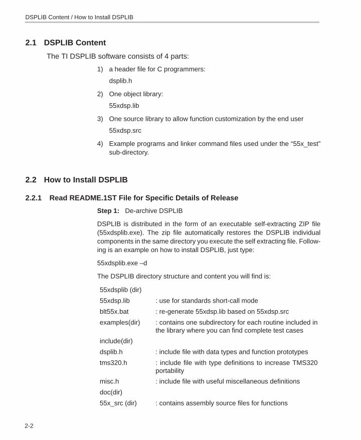
2.1 DSPLIB Content
The TI DSPLIB software consists of 4 parts:
1) a header file for C programmers:
dsplib.h
2) One object library:
55xdsp.lib
3) One source library to allow function customization by the end user
55xdsp.src
4) Example programs and linker command files used under the “55x_test”sub-directory.
2.2 How to Install DSPLIB
2.2.1 Read README.1ST File for Specific Details of Release
Step 1: De-archive DSPLIB
DSPLIB is distributed in the form of an executable self-extracting ZIP file(55xdsplib.exe). The zip file automatically restores the DSPLIB individualcomponents in the same directory you execute the self extracting file. Follow-ing is an example on how to install DSPLIB, just type:
55xdsplib.exe –d
The DSPLIB directory structure and content you will find is:
55xdsplib (dir)
55xdsp.lib : use for standards short-call mode
blt55x.bat : re-generate 55xdsp.lib based on 55xdsp.src
examples(dir) : contains one subdirectory for each routine included inthe library where you can find complete test cases
include(dir)
dsplib.h : include file with data types and function prototypes
tms320.h : include file with type definitions to increase TMS320portability
misc.h : include file with useful miscellaneous definitions
doc(dir)
55x_src (dir) : contains assembly source files for functions
DSPLIB Content / How to Install DSPLIB
How to Rebuild DSPLIB
2-3Installing DSPLIB
Step 2: Relocate library file
Copy the C55x DSPLIB object library file, 55xdsp.lib, to your C5500 runtimesupport library folder.
For example, if your TI C5500 tools are located in c:\ti\c5500\cgtools\bin andc runtime support libraries (rts55.lib etc.) in c:\ti\c5500\cgtools\lib, copy55xdsplib.lib to this folder. This allows the C55x compiler/linker to find55xdsp.lib.
2.3 How to Rebuild DSPLIB
2.3.1 For Full Rebuild of 55xdsp.lib
To rebuild 55xdsp.lib, execute the blt55x.bat. This will overwrite any existing55xdsp.lib.
2.3.2 For Partial Rebuild of 55xdsp.lib(modification of a specific DSPLIB function, for example fir.asm)
1) Extract the source for the selected function from the source archive:
ar55 x 55xdsp.src fir.asm
2) Re-assemble your new fir.asm assembly source file:
asm55 –g fir.asm
3) Replace the object , fir.obj, in the dsplib.lib object library with the newlyformed object:
ar55 r 55xdsp.lib fir.obj
How to Install DSPLIB / How to Rebuild DSPLIB
3-1
Using DSPLIB
This chapter describes how to use the DSPLIB.
Topic Page
3.1 DSP Arguments and Data Types 3-2. . . . . . . . . . . . . . . . . . . . . . . . . . . . . . . .
3.2 Calling a DSPLIB Function from C 3-3. . . . . . . . . . . . . . . . . . . . . . . . . . . . . .
3.3 Calling a DSPLIB Function from Assembly LanguageSource Code 3-5. . . . . . . . . . . . . . . . . . . . . . . . . . . . . . . . . . . . . . . . . . . . . . . . .
3.4 Where to Find Sample Code 3-5. . . . . . . . . . . . . . . . . . . . . . . . . . . . . . . . . . .
3.5 How DSPLIB is Tested — Allowable Error 3-6. . . . . . . . . . . . . . . . . . . . . . .
3.6 How DSPLIB Deals with Overflow and Scaling Issues 3-6. . . . . . . . . . . .
3.7 Where DSPLIB Goes from Here 3-8. . . . . . . . . . . . . . . . . . . . . . . . . . . . . . . .
Chapter 3
DSPLIB Arguments and Data Types
3-2
3.1 DSPLIB Arguments and Data Types
3.1.1 DSPLIB Arguments
DSPLIB functions typically operate over vector operands for greater efficiency.Though these routines can be used to process short arrays or scalars (unlessa minimum size requirement is noted) , the execution times will be longer inthose cases.
� Vector stride is always equal 1: vector operands are composed of vectorelements held in consecutive memory locations (vector stride equal to 1).
� Complex elements are assumed to be stored in a Re-Im format.
� In-place computation is allowed (unless specifically noted): Sourceoperand can be equal to destination operand to conserve memory.
3.1.2 DSPLIB Data Types
DSPLIB handles the following fractional data types:
� Q.15 (DATA) : A Q.15 operand is represented by a short data type (16 bit)that is predefined as DATA, in the dsplib.h header file.
� Q.31 (LDATA) : A Q.31 operand is represented by a long data type (32 bit)that is predefined as LDATA, in the dsplib.h header file.
� Q.3.12 : Contains 3 integer bits and 12 fractional bits.
Unless specifically noted, DSPLIB operates on Q15-fractional data typeelements. Appendix A presents an overview of Fractional Q formats
Calling a DSPLIB Function from C
3-3Using DSPLIB
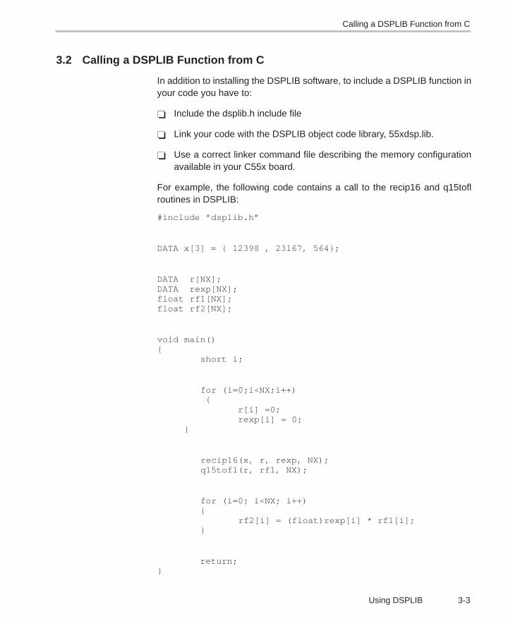
3.2 Calling a DSPLIB Function from C
In addition to installing the DSPLIB software, to include a DSPLIB function inyour code you have to:
� Include the dsplib.h include file
� Link your code with the DSPLIB object code library, 55xdsp.lib.
� Use a correct linker command file describing the memory configurationavailable in your C55x board.
For example, the following code contains a call to the recip16 and q15toflroutines in DSPLIB:
#include ”dsplib.h”
DATA x[3] = { 12398 , 23167, 564};
DATA r[NX];DATA rexp[NX];float rf1[NX];float rf2[NX];
void main(){ short i;
for (i=0;i<NX;i++) { r[i] =0; rexp[i] = 0; }
recip16(x, r, rexp, NX); q15tofl(r, rf1, NX);
for (i=0; i<NX; i++) { rf2[i] = (float)rexp[i] * rf1[i]; }
return;}

Calling a DSPLIB Function from C
3-4
In this example, the q15tofl DSPLIB function is used to convert Q15 fractionalvalues to floating point fractional values. However, in many applications, yourdata is always maintained in Q15 format so that the conversion between floatand Q15 is not required.
The above code, ug.c, is available to you in the /doc/code subdirectory. Tocompile and link this code with 55xdsp.lib, issue the following command:
cl55 –pk –g –o3 –i. ug.c –z –v0 ld3.cmd 55xdsp.lib –m ug.map –oug.out
The examples presented in this document have been tested using the TexasInstruments C55x Simulator. Customization may be required to use it with adifferent simulator or development board.
Refer to the TMS320C55x Optimizing C Compiler User’s Guide (SPRU281).
Calling a DSPLIB Function from Assembly Language Source Code
3-5Using DSPLIB
3.3 Calling a DSPLIB Function from Assembly Language Source Code
The TMS320C55x DSPLIB functions were written to be used from C. Callingthe functions from assembly language source code is possible as long as thecalling-function conforms with the Texas Instruments C55x C compiler callingconventions. Refer to the TMS320C55x Optimizing C Compiler User’s Guide,if a more in-depth explanation is required.
Realize that the TI DSPLIB is not an optimal solution for assembly-onlyprogrammers. Even though DSPLIB functions can be invoked from anassembly program, the result may not be optimal due to unnecessary C-callingoverhead.
3.4 Where to Find Sample Code
You can find examples on how to use every single function in DSPLIB, in theexamples subdirectory. This subdirectory contains one subdirectory for eachfunction. For example, the examples/araw subdirectory contains the followingfiles:
� araw_t.c: main driver for testing the DSPLIB acorr (raw) function.
� test.h: contains input data(a) and expected output data(yraw) for the acorr(raw) function as. This test.h file is generated by using Matlab scripts.
� test.c: contains function used to compare the output of araw function withthe expected output data.
� ftest.c: contains function used to compare two arrays of float data types.
� ltest.c: contains function used to compare two arrays of long data types.
� ld3.cmd: an example of a linker command you can use for this function.
How DSPLIB is Tested – Allowable Error
3-6
3.5 How DSPLIB is Tested – Allowable Error
Version 1.0 of DSPLIB is tested against Matlab scripts. Expected data outputhas been generated from Matlab that uses double-precision (64-bit) floating-point operations (default precision in Matlab). Test utilities have been addedto our test main drivers to automate this checking process. Note that a maxi-mum absolute error value (MAXERROR) is passed to the test function, to setthe trigger point to flag a functional error.
We consider this testing methodology a good first pass approximation. Furthercharacterization of the quantization error ranges for each function (under ran-dom input) as well as testing against a set of fixed-point C models is plannedfor future releases. We welcome any suggestions you may have on thisrespect.
3.6 How DSPLIB Deals with Overflow and Scaling Issues
One of the inherent difficulties of programming for fixed-point processors isdetermining how to deal with overflow issues. Overflow occurs as a result ofaddition and subtraction operations when the dynamic range of the resultingdata is larger than what the intermediate and final data types can contain.
The methodology used to deal with overflow should depend on the specificsof your signal, the type of operation in your functions, and the DSP architectureused. In general, overflow handling methodologies can be classified in fivecategories: saturation, input scaling, fixed scaling, dynamic scaling, andsystem design considerations.
It’s important to note that a TMS320C55x architectural feature that makesoverflow easier to deal with is the presence of guard bits in all four accumula-tors. The 40-bit accumulators provide eight guard bits that allow up to 256 con-secutive multiply-and-accumulate (MAC) operations before an accumulatoroverrun – a very useful feature when implementing, for example, FIR filters.
There are 4 specific ways DSPLIB deals with overflow, as reflected in eachfunction description:
� Scaling implemented for overflow prevention: In this type of function,DSPLIB scales the intermediate results to prevent overflow. Overflowshould not occur as a result. Precision is affected but not significantly. Thisis the case of the FFT functions, in which scaling is used after each FFTstage.
How DSPLIB Deals with Overflow and Scaling Issues
3-7Using DSPLIB
� No scaling implemented for overflow prevention: In this type of func-tion, DSPLIB does not scale to prevent overflow due to the potentiallystrong effect in data output precision or in the number of cycles required.This is the case, for example, of the MAC-based operations like filtering,correlation, or convolutions. The best solution on those cases is to designyour system , for example your filter coefficients with a gain less than 1 toprevent overflow. In this case, overflow could happen unless you inputscale or you design for no overflow.
� Saturation implemented for overflow handling: In this type of function,DSPLIB has enabled the TMS320C55x 32-bit saturation mode (SATDbit = 1). This is the case of certain basic math functions that require thesaturation mode to be enabled.
� Not applicable: In this type of function, due to the nature of the functionoperations, there is no overflow.
� DSPLIB reporting of overflow conditions (overflow flag): Due to thesometimes unpredictible overflow risk, most DSPLIB functions have beenwritten to return an overflow flag (oflag) as an indication of a potentiallydangerous 32-bit overflow. However, because of the guard-bits, the C55xis capable of handling intermediate 32-bit overflows and still produce thecorrect final result. Therefore, the oflag parameter should be taken in thecontext of a warning but not a definitive error.
As a final note, DSPLIB is provided also in source format to allow customiza-tion of DSPLIB functions to your specific system needs.
Where DSPLIB Goes from Here
3-8
3.7 Where DSPLIB Goes from Here
We anticipate DSPLIB to improve in future releases in the following areas:
� Increased number of functions: We anticipate the number of functionsin DSPLIB will increase. We welcome user-contributed code. If during theprocess of developing your application you develop a DSP routine thatseems like a good fit to DSPLIB, let us know. We will review and test yourroutine and possibly include it in the next DSPLIB software release. Yourcontribution will be acknowledged and recognized by TI in the Acknowl-edgments section. Use this opportunity to make your name known by yourDSP industry peers. Simply email your contribution To Whom It May Con-cern: [email protected] and we will contact you.
� Increased Code portability: DSPLIB looks to enhance code portabilityacross different TMS320-based platforms. It is our goal to provide similarDSP libraries for other TMS320 devices, working in conjunction withC55x compiler intrinsics to make C-developing easier for fixed-pointdevices. However, it’s anticipated that a 100% portable library acrossTMS320 devices may not be possible due to normal device architecturaldifferences. TI will continue monitoring DSP industry standardization acti-vities in terms of DSP function libraries.
4-1
Function Descriptions
This chapter provides descriptions for the TMS330C55x DSPLIB functions.
Topic Page
4.1 Arguments and Conventions Used 4-2. . . . . . . . . . . . . . . . . . . . . . . . . . . . .
4.2 DSPLIB Functions 4-3. . . . . . . . . . . . . . . . . . . . . . . . . . . . . . . . . . . . . . . . . . . .
Chapter 4
Arguments and Conventions Used
4-2
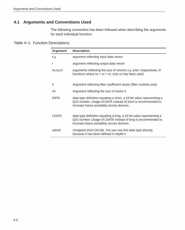
4.1 Arguments and Conventions Used
The following convention has been followed when describing the argumentsfor each individual function:
Table 4–1. Function Descriptions
Argument Description
x,y argument reflecting input data vector
r argument reflecting output data vector
nx,ny,nr arguments reflecting the size of vectors x,y, and r respectively. Infunctions where nx = nr = nr, only nx has been used.
h Argument reflecting filter coefficient vector (filter routines only)
nh Argument reflecting the size of vector h
DATA data type definition equating a short, a 16-bit value representing aQ15 number. Usage of DATA instead of short is recommended toincrease future portability across devices.
LDATA data type definition equating a long, a 32-bit value representing aQ31 number. Usage of LDATA instead of long is recommended toincrease future portability across devices.
ushort Unsigned short (16 bit). You can use this data type directly,because it has been defined in dsplib.h
DSPLIB Functions
4-3Function Descriptions
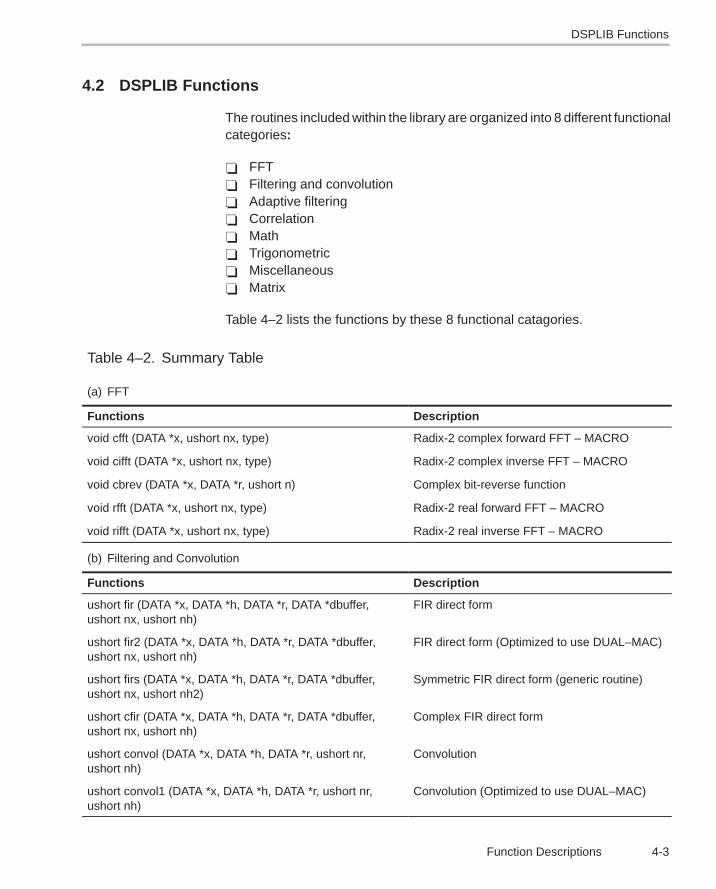
4.2 DSPLIB Functions
The routines included within the library are organized into 8 different functionalcategories:
� FFT� Filtering and convolution� Adaptive filtering� Correlation� Math� Trigonometric� Miscellaneous� Matrix
Table 4–2 lists the functions by these 8 functional catagories.
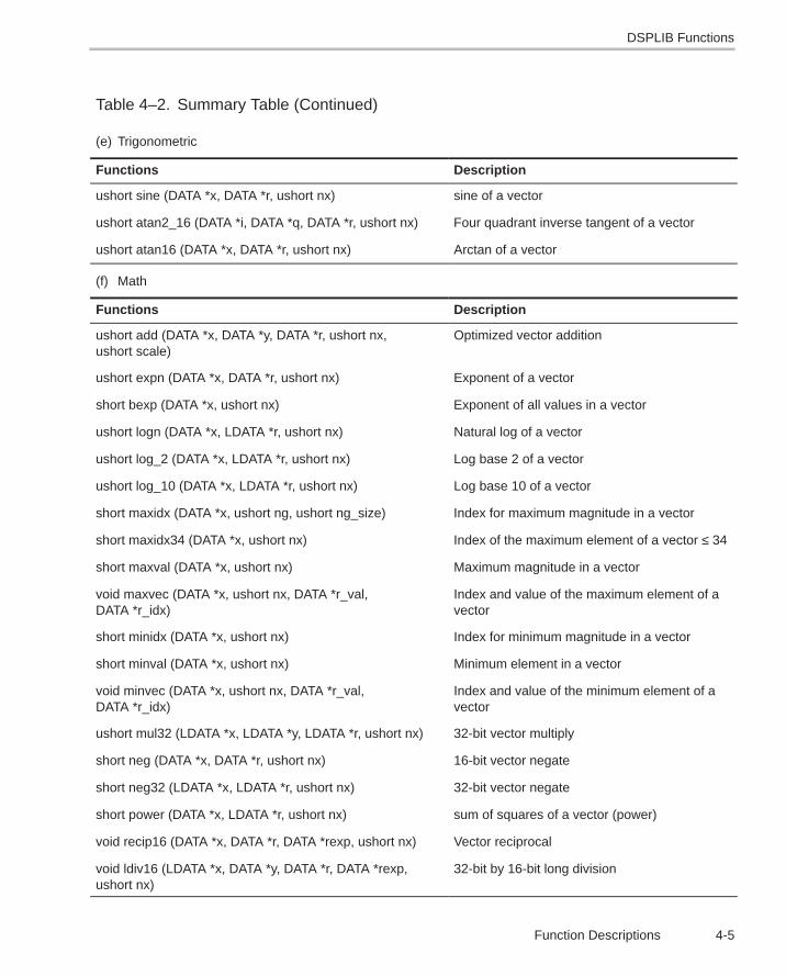
Table 4–2. Summary Table
(a) FFT
Functions Description
void cfft (DATA *x, ushort nx, type) Radix-2 complex forward FFT – MACRO
void cifft (DATA *x, ushort nx, type) Radix-2 complex inverse FFT – MACRO
void cbrev (DATA *x, DATA *r, ushort n) Complex bit-reverse function
void rfft (DATA *x, ushort nx, type) Radix-2 real forward FFT – MACRO
void rifft (DATA *x, ushort nx, type) Radix-2 real inverse FFT – MACRO
(b) Filtering and Convolution
Functions Description
ushort fir (DATA *x, DATA *h, DATA *r, DATA *dbuffer,ushort nx, ushort nh)
FIR direct form
ushort fir2 (DATA *x, DATA *h, DATA *r, DATA *dbuffer,ushort nx, ushort nh)
FIR direct form (Optimized to use DUAL–MAC)
ushort firs (DATA *x, DATA *h, DATA *r, DATA *dbuffer,ushort nx, ushort nh2)
Symmetric FIR direct form (generic routine)
ushort cfir (DATA *x, DATA *h, DATA *r, DATA *dbuffer,ushort nx, ushort nh)
Complex FIR direct form
ushort convol (DATA *x, DATA *h, DATA *r, ushort nr,ushort nh)
Convolution
ushort convol1 (DATA *x, DATA *h, DATA *r, ushort nr,ushort nh)
Convolution (Optimized to use DUAL–MAC)
DSPLIB Functions
4-4
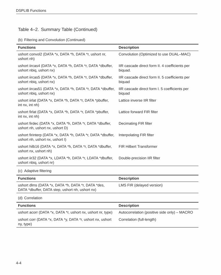
Table 4–2. Summary Table (Continued)
(b) Filtering and Convolution (Continued)
Functions Description
ushort convol2 (DATA *x, DATA *h, DATA *r, ushort nr,ushort nh)
Convolution (Optimized to use DUAL–MAC)
ushort iircas4 (DATA *x, DATA *h, DATA *r, DATA *dbuffer,ushort nbiq, ushort nx)
IIR cascade direct form II. 4 coefficients perbiquad.
ushort iircas5 (DATA *x, DATA *h, DATA *r, DATA *dbuffer,ushort nbiq, ushort nx)
IIR cascade direct form II. 5 coefficients perbiquad
ushort iircas51 (DATA *x, DATA *h, DATA *r, DATA *dbuffer,ushort nbiq, ushort nx)
IIR cascade direct form I. 5 coefficients perbiquad
ushort iirlat (DATA *x, DATA *h, DATA *r, DATA *pbuffer,int nx, int nh)
Lattice inverse IIR filter
ushort firlat (DATA *x, DATA *h, DATA *r, DATA *pbuffer,int nx, int nh)
Lattice forward FIR filter
ushort firdec (DATA *x, DATA *h, DATA *r, DATA *dbuffer,ushort nh, ushort nx, ushort D)
Decimating FIR filter
ushort firinterp (DATA *x, DATA *h, DATA *r, DATA *dbuffer,ushort nh, ushort nx, ushort I)
Interpolating FIR filter
ushort hilb16 (DATA *x, DATA *h, DATA *r, DATA *dbuffer,ushort nx, ushort nh)
FIR Hilbert Transformer
ushort iir32 (DATA *x, LDATA *h, DATA *r, LDATA *dbuffer,ushort nbiq, ushort nr)
Double-precision IIR filter
(c) Adaptive filtering
Functions Description
ushort dlms (DATA *x, DATA *h, DATA *r, DATA *des,DATA *dbuffer, DATA step, ushort nh, ushort nx)
LMS FIR (delayed version)
(d) Correlation
Functions Description
ushort acorr (DATA *x, DATA *r, ushort nx, ushort nr, type) Autocorrelation (positive side only) – MACRO
ushort corr (DATA *x, DATA *y, DATA *r, ushort nx, ushortny, type)
Correlation (full-length)
DSPLIB Functions
4-5Function Descriptions
Table 4–2. Summary Table (Continued)
(e) Trigonometric
Functions Description
ushort sine (DATA *x, DATA *r, ushort nx) sine of a vector
ushort atan2_16 (DATA *i, DATA *q, DATA *r, ushort nx) Four quadrant inverse tangent of a vector
ushort atan16 (DATA *x, DATA *r, ushort nx) Arctan of a vector
(f) Math
Functions Description
ushort add (DATA *x, DATA *y, DATA *r, ushort nx,ushort scale)
Optimized vector addition
ushort expn (DATA *x, DATA *r, ushort nx) Exponent of a vector
short bexp (DATA *x, ushort nx) Exponent of all values in a vector
ushort logn (DATA *x, LDATA *r, ushort nx) Natural log of a vector
ushort log_2 (DATA *x, LDATA *r, ushort nx) Log base 2 of a vector
ushort log_10 (DATA *x, LDATA *r, ushort nx) Log base 10 of a vector
short maxidx (DATA *x, ushort ng, ushort ng_size) Index for maximum magnitude in a vector
short maxidx34 (DATA *x, ushort nx) Index of the maximum element of a vector ≤ 34
short maxval (DATA *x, ushort nx) Maximum magnitude in a vector
void maxvec (DATA *x, ushort nx, DATA *r_val,DATA *r_idx)
Index and value of the maximum element of avector
short minidx (DATA *x, ushort nx) Index for minimum magnitude in a vector
short minval (DATA *x, ushort nx) Minimum element in a vector
void minvec (DATA *x, ushort nx, DATA *r_val,DATA *r_idx)
Index and value of the minimum element of avector
ushort mul32 (LDATA *x, LDATA *y, LDATA *r, ushort nx) 32-bit vector multiply
short neg (DATA *x, DATA *r, ushort nx) 16-bit vector negate
short neg32 (LDATA *x, LDATA *r, ushort nx) 32-bit vector negate
short power (DATA *x, LDATA *r, ushort nx) sum of squares of a vector (power)
void recip16 (DATA *x, DATA *r, DATA *rexp, ushort nx) Vector reciprocal
void ldiv16 (LDATA *x, DATA *y, DATA *r, DATA *rexp,ushort nx)
32-bit by 16-bit long division
DSPLIB Functions
4-6
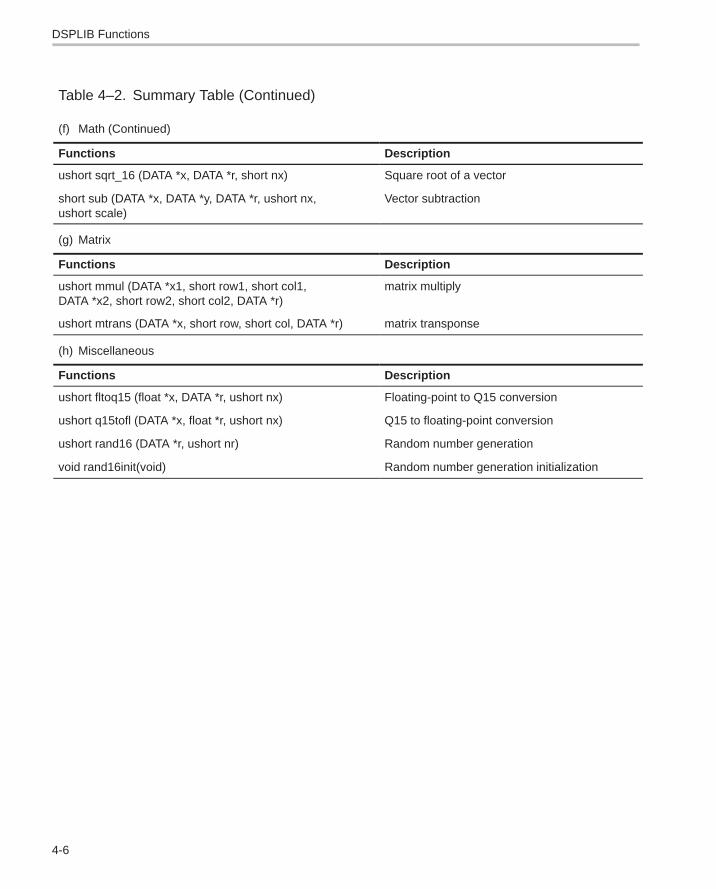
Table 4–2. Summary Table (Continued)
(f) Math (Continued)
Functions Description
ushort sqrt_16 (DATA *x, DATA *r, short nx) Square root of a vector
short sub (DATA *x, DATA *y, DATA *r, ushort nx,ushort scale)
Vector subtraction
(g) Matrix
Functions Description
ushort mmul (DATA *x1, short row1, short col1,DATA *x2, short row2, short col2, DATA *r)
matrix multiply
ushort mtrans (DATA *x, short row, short col, DATA *r) matrix transponse
(h) Miscellaneous
Functions Description
ushort fltoq15 (float *x, DATA *r, ushort nx) Floating-point to Q15 conversion
ushort q15tofl (DATA *x, float *r, ushort nx) Q15 to floating-point conversion
ushort rand16 (DATA *r, ushort nr) Random number generation
void rand16init(void) Random number generation initialization
acorr
4-7 Function Descriptions
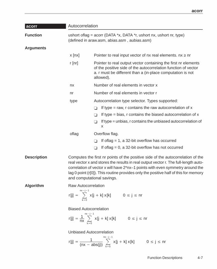
Autocorrelationacorr
Function ushort oflag = acorr (DATA *x, DATA *r, ushort nx, ushort nr, type)(defined in araw.asm, abias.asm , aubias.asm)
Arguments
x [nx] Pointer to real input vector of nx real elements. nx ≥ nr
r [nr] Pointer to real output vector containing the first nr elementsof the positive side of the autocorrelation function of vectora. r must be different than a (in-place computation is notallowed).
nx Number of real elements in vector x
nr Number of real elements in vector r
type Autocorrelation type selector. Types supported:
� If type = raw, r contains the raw autocorrelation of x
� If type = bias, r contains the biased autocorrelation of x
� If type = unbias, r contains the unbiased autocorrelation ofx
oflag Overflow flag.
� If oflag = 1, a 32-bit overflow has occurred
� If oflag = 0, a 32-bit overflow has not occurred
Description Computes the first nr points of the positive side of the autocorrelation of thereal vector x and stores the results in real output vector r. The full-length auto-correlation of vector x will have 2*nx–1 points with even symmetry around thelag 0 point (r[0]). This routine provides only the positive half of this for memoryand computational savings.
Algorithm Raw Autocorrelation
r [j] � �nx�j�1
k�0
x [j � k] x [k] 0 � j � nr
Biased Autocorrelation
r [j] � 1nx�
nx�j�1
k�0
x [j � k] x [k] 0 � j � nr
Unbiased Autocorrelation
r [j] � 1(nx � abs(j))
�nx�j�1
k�0
x [j � k] x [k] 0 � j � nr
acorr
4-8
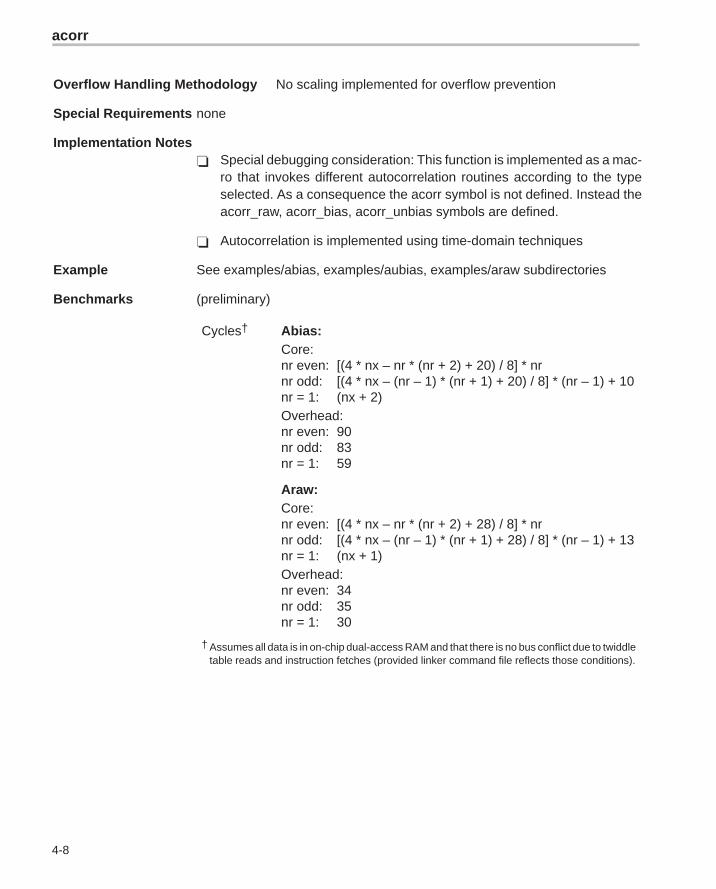
Overflow Handling Methodology No scaling implemented for overflow prevention
Special Requirements none
Implementation Notes� Special debugging consideration: This function is implemented as a mac-
ro that invokes different autocorrelation routines according to the typeselected. As a consequence the acorr symbol is not defined. Instead theacorr_raw, acorr_bias, acorr_unbias symbols are defined.
� Autocorrelation is implemented using time-domain techniques
Example See examples/abias, examples/aubias, examples/araw subdirectories
Benchmarks (preliminary)
Cycles† Abias:Core:nr even: [(4 * nx – nr * (nr + 2) + 20) / 8] * nrnr odd: [(4 * nx – (nr – 1) * (nr + 1) + 20) / 8] * (nr – 1) + 10nr = 1: (nx + 2)Overhead:nr even: 90nr odd: 83nr = 1: 59
Araw:Core:nr even: [(4 * nx – nr * (nr + 2) + 28) / 8] * nrnr odd: [(4 * nx – (nr – 1) * (nr + 1) + 28) / 8] * (nr – 1) + 13nr = 1: (nx + 1)Overhead:nr even: 34nr odd: 35nr = 1: 30
† Assumes all data is in on-chip dual-access RAM and that there is no bus conflict due to twiddletable reads and instruction fetches (provided linker command file reflects those conditions).
add
4-9 Function Descriptions
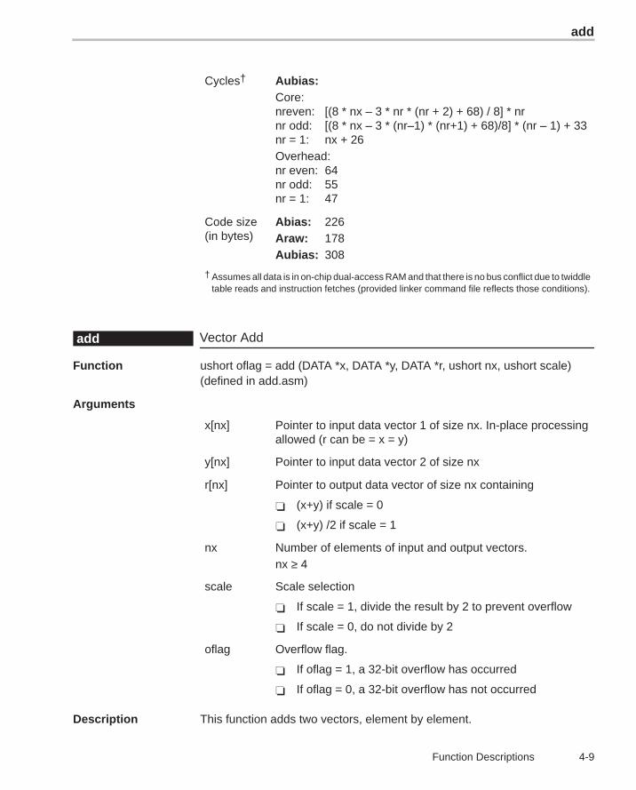
Cycles† Aubias:Core:nreven: [(8 * nx – 3 * nr * (nr + 2) + 68) / 8] * nrnr odd: [(8 * nx – 3 * (nr–1) * (nr+1) + 68)/8] * (nr – 1) + 33nr = 1: nx + 26Overhead:nr even: 64nr odd: 55nr = 1: 47
Code size(in bytes)
Abias: 226Araw: 178Aubias: 308
† Assumes all data is in on-chip dual-access RAM and that there is no bus conflict due to twiddletable reads and instruction fetches (provided linker command file reflects those conditions).
Vector Addadd
Function ushort oflag = add (DATA *x, DATA *y, DATA *r, ushort nx, ushort scale)(defined in add.asm)
Arguments
x[nx] Pointer to input data vector 1 of size nx. In-place processingallowed (r can be = x = y)
y[nx] Pointer to input data vector 2 of size nx
r[nx] Pointer to output data vector of size nx containing
� (x+y) if scale = 0
� (x+y) /2 if scale = 1
nx Number of elements of input and output vectors.nx ≥ 4
scale Scale selection
� If scale = 1, divide the result by 2 to prevent overflow
� If scale = 0, do not divide by 2
oflag Overflow flag.
� If oflag = 1, a 32-bit overflow has occurred
� If oflag = 0, a 32-bit overflow has not occurred
Description This function adds two vectors, element by element.
atan2_16
4-10
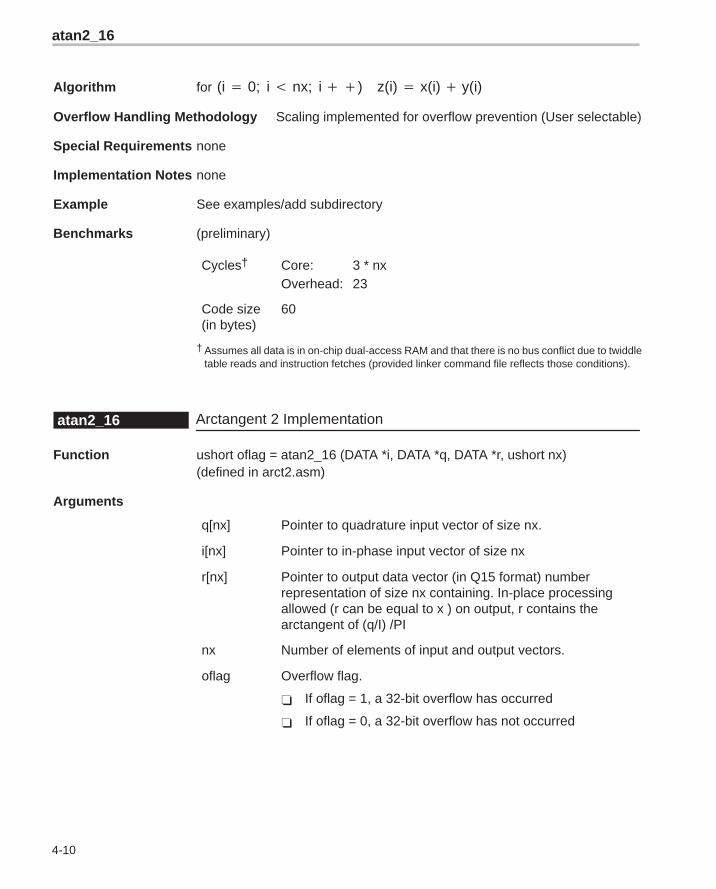
Algorithm for (i � 0; i � nx; i ��) z(i) � x(i) � y(i)
Overflow Handling Methodology Scaling implemented for overflow prevention (User selectable)
Special Requirements none
Implementation Notes none
Example See examples/add subdirectory
Benchmarks (preliminary)
Cycles† Core: 3 * nxOverhead: 23
Code size(in bytes)
60
† Assumes all data is in on-chip dual-access RAM and that there is no bus conflict due to twiddletable reads and instruction fetches (provided linker command file reflects those conditions).
Arctangent 2 Implementationatan2_16
Function ushort oflag = atan2_16 (DATA *i, DATA *q, DATA *r, ushort nx)(defined in arct2.asm)
Arguments
q[nx] Pointer to quadrature input vector of size nx.
i[nx] Pointer to in-phase input vector of size nx
r[nx] Pointer to output data vector (in Q15 format) numberrepresentation of size nx containing. In-place processingallowed (r can be equal to x ) on output, r contains thearctangent of (q/I) /PI
nx Number of elements of input and output vectors.
oflag Overflow flag.
� If oflag = 1, a 32-bit overflow has occurred
� If oflag = 0, a 32-bit overflow has not occurred
atan16
4-11 Function Descriptions
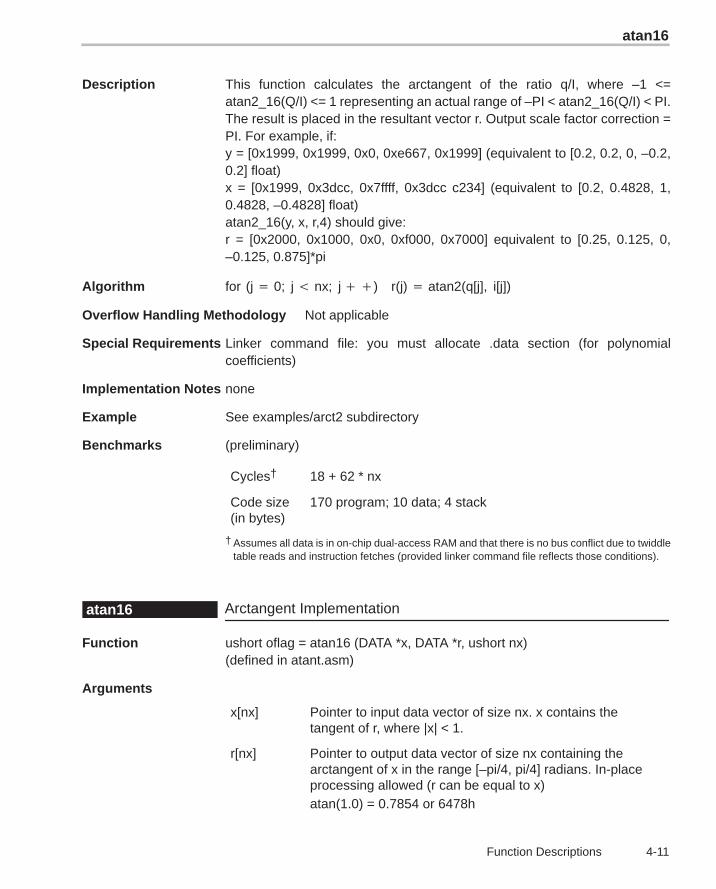
Description This function calculates the arctangent of the ratio q/I, where –1 <=atan2_16(Q/I) <= 1 representing an actual range of –PI < atan2_16(Q/I) < PI.The result is placed in the resultant vector r. Output scale factor correction =PI. For example, if:y = [0x1999, 0x1999, 0x0, 0xe667, 0x1999] (equivalent to [0.2, 0.2, 0, –0.2,0.2] float)x = [0x1999, 0x3dcc, 0x7ffff, 0x3dcc c234] (equivalent to [0.2, 0.4828, 1,0.4828, –0.4828] float)atan2_16(y, x, r,4) should give: r = [0x2000, 0x1000, 0x0, 0xf000, 0x7000] equivalent to [0.25, 0.125, 0,–0.125, 0.875]*pi
Algorithm for (j � 0; j � nx; j ��) r(j) � atan2(q[j], i[j])
Overflow Handling Methodology Not applicable
Special Requirements Linker command file: you must allocate .data section (for polynomialcoefficients)
Implementation Notes none
Example See examples/arct2 subdirectory
Benchmarks (preliminary)
Cycles† 18 + 62 * nx
Code size(in bytes)
170 program; 10 data; 4 stack
† Assumes all data is in on-chip dual-access RAM and that there is no bus conflict due to twiddletable reads and instruction fetches (provided linker command file reflects those conditions).
Arctangent Implementationatan16
Function ushort oflag = atan16 (DATA *x, DATA *r, ushort nx)(defined in atant.asm)
Arguments
x[nx] Pointer to input data vector of size nx. x contains thetangent of r, where |x| < 1.
r[nx] Pointer to output data vector of size nx containing thearctangent of x in the range [–pi/4, pi/4] radians. In-placeprocessing allowed (r can be equal to x)atan(1.0) = 0.7854 or 6478h
atan16
4-12
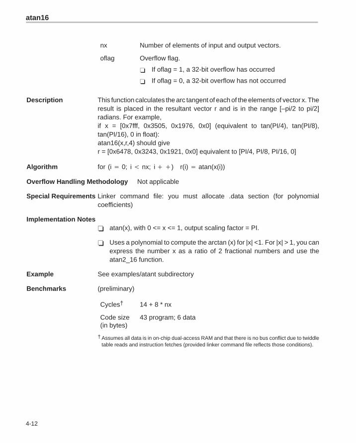
nx Number of elements of input and output vectors.
oflag Overflow flag.
� If oflag = 1, a 32-bit overflow has occurred
� If oflag = 0, a 32-bit overflow has not occurred
Description This function calculates the arc tangent of each of the elements of vector x. Theresult is placed in the resultant vector r and is in the range [–pi/2 to pi/2]radians. For example,if x = [0x7fff, 0x3505, 0x1976, 0x0] (equivalent to tan(PI/4), tan(PI/8),tan(PI/16), 0 in float):atan16(x,r,4) should giver = [0x6478, 0x3243, 0x1921, 0x0] equivalent to [PI/4, PI/8, PI/16, 0]
Algorithm for (i � 0; i � nx; i ��) r(i) � atan(x(i))
Overflow Handling Methodology Not applicable
Special Requirements Linker command file: you must allocate .data section (for polynomialcoefficients)
Implementation Notes� atan(x), with 0 <= x <= 1, output scaling factor = PI.
� Uses a polynomial to compute the arctan (x) for |x| <1. For |x| > 1, you canexpress the number x as a ratio of 2 fractional numbers and use theatan2_16 function.
Example See examples/atant subdirectory
Benchmarks (preliminary)
Cycles† 14 + 8 * nx
Code size(in bytes)
43 program; 6 data
† Assumes all data is in on-chip dual-access RAM and that there is no bus conflict due to twiddletable reads and instruction fetches (provided linker command file reflects those conditions).
bexp
4-13 Function Descriptions
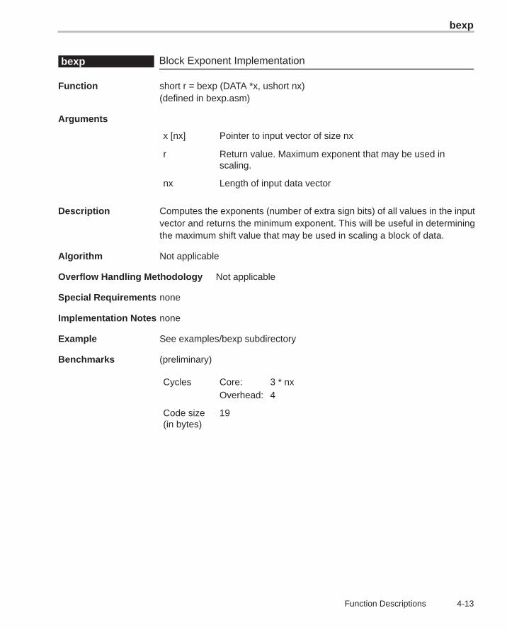
Block Exponent Implementationbexp
Function short r = bexp (DATA *x, ushort nx)(defined in bexp.asm)
Arguments
x [nx] Pointer to input vector of size nx
r Return value. Maximum exponent that may be used inscaling.
nx Length of input data vector
Description Computes the exponents (number of extra sign bits) of all values in the inputvector and returns the minimum exponent. This will be useful in determiningthe maximum shift value that may be used in scaling a block of data.
Algorithm Not applicable
Overflow Handling Methodology Not applicable
Special Requirements none
Implementation Notes none
Example See examples/bexp subdirectory
Benchmarks (preliminary)
Cycles Core: 3 * nxOverhead: 4
Code size(in bytes)
19
cbrev
4-14
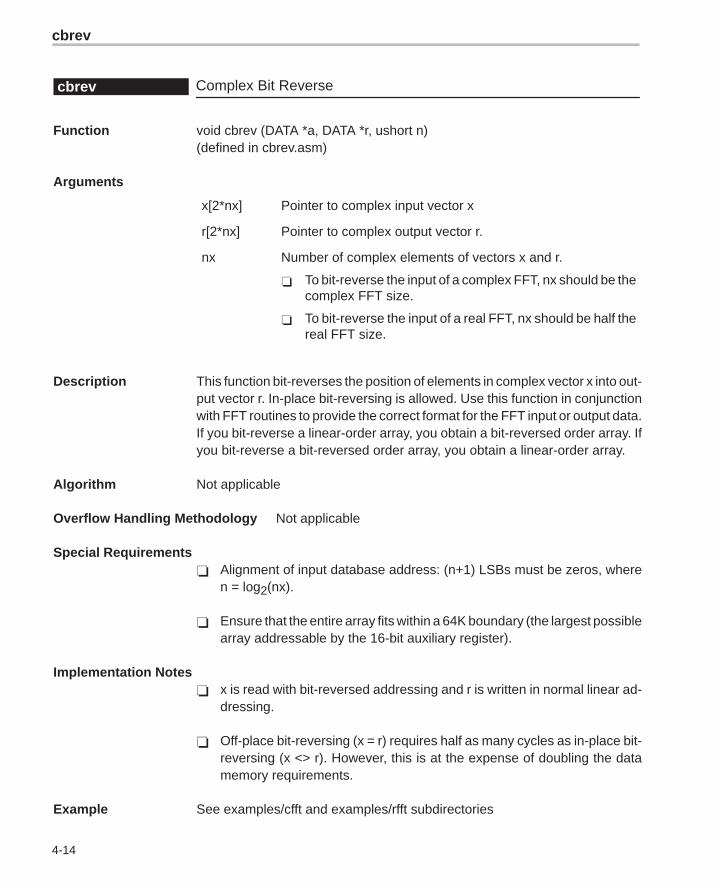
Complex Bit Reversecbrev
Function void cbrev (DATA *a, DATA *r, ushort n)(defined in cbrev.asm)
Arguments
x[2*nx] Pointer to complex input vector x
r[2*nx] Pointer to complex output vector r.
nx Number of complex elements of vectors x and r.
� To bit-reverse the input of a complex FFT, nx should be thecomplex FFT size.
� To bit-reverse the input of a real FFT, nx should be half thereal FFT size.
Description This function bit-reverses the position of elements in complex vector x into out-put vector r. In-place bit-reversing is allowed. Use this function in conjunctionwith FFT routines to provide the correct format for the FFT input or output data.If you bit-reverse a linear-order array, you obtain a bit-reversed order array. Ifyou bit-reverse a bit-reversed order array, you obtain a linear-order array.
Algorithm Not applicable
Overflow Handling Methodology Not applicable
Special Requirements� Alignment of input database address: (n+1) LSBs must be zeros, where
n = log2(nx).
� Ensure that the entire array fits within a 64K boundary (the largest possiblearray addressable by the 16-bit auxiliary register).
Implementation Notes� x is read with bit-reversed addressing and r is written in normal linear ad-
dressing.
� Off-place bit-reversing (x = r) requires half as many cycles as in-place bit-reversing (x <> r). However, this is at the expense of doubling the datamemory requirements.
Example See examples/cfft and examples/rfft subdirectories
cfft
4-15 Function Descriptions
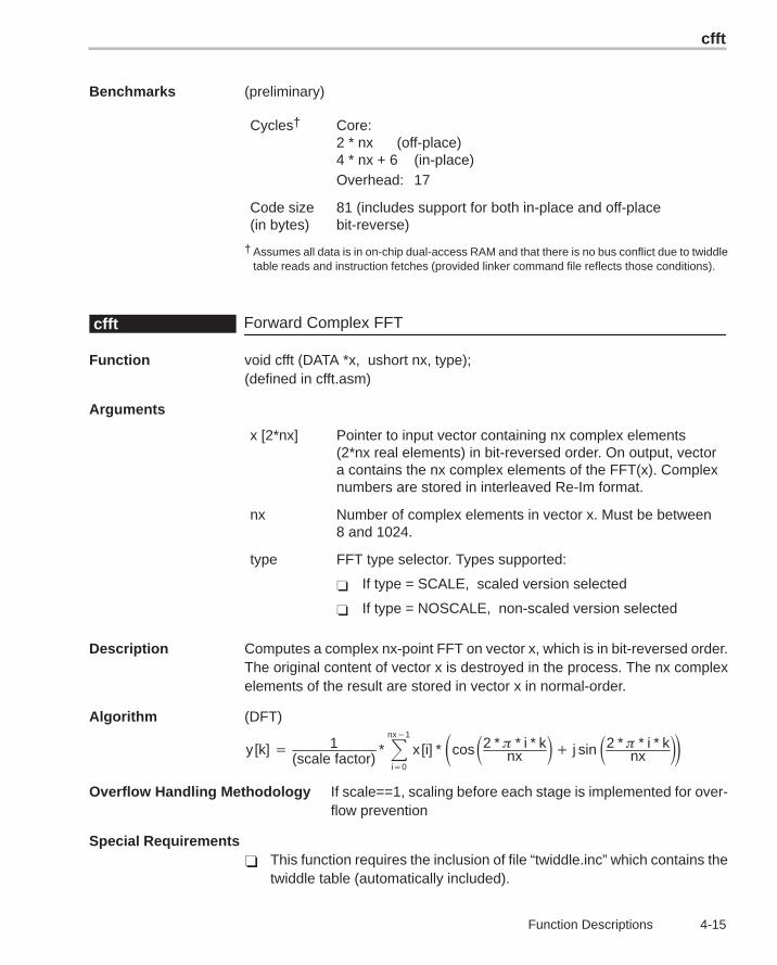
Benchmarks (preliminary)
Cycles† Core:2 * nx (off-place)4 * nx + 6 (in-place)Overhead: 17
Code size(in bytes)
81 (includes support for both in-place and off-placebit-reverse)
† Assumes all data is in on-chip dual-access RAM and that there is no bus conflict due to twiddletable reads and instruction fetches (provided linker command file reflects those conditions).
Forward Complex FFTcfft
Function void cfft (DATA *x, ushort nx, type);(defined in cfft.asm)
Arguments
x [2*nx] Pointer to input vector containing nx complex elements(2*nx real elements) in bit-reversed order. On output, vectora contains the nx complex elements of the FFT(x). Complexnumbers are stored in interleaved Re-Im format.
nx Number of complex elements in vector x. Must be between8 and 1024.
type FFT type selector. Types supported:
� If type = SCALE, scaled version selected
� If type = NOSCALE, non-scaled version selected
Description Computes a complex nx-point FFT on vector x, which is in bit-reversed order.The original content of vector x is destroyed in the process. The nx complexelements of the result are stored in vector x in normal-order.
Algorithm (DFT)
y [k] � 1(scale factor)
* �nx�1
i�0
x [i] * �cos�2 * � * i * knx �� j sin �2 * � * i * k
nx ��
Overflow Handling Methodology If scale==1, scaling before each stage is implemented for over-flow prevention
Special Requirements� This function requires the inclusion of file “twiddle.inc” which contains the
twiddle table (automatically included).
cfft
4-16
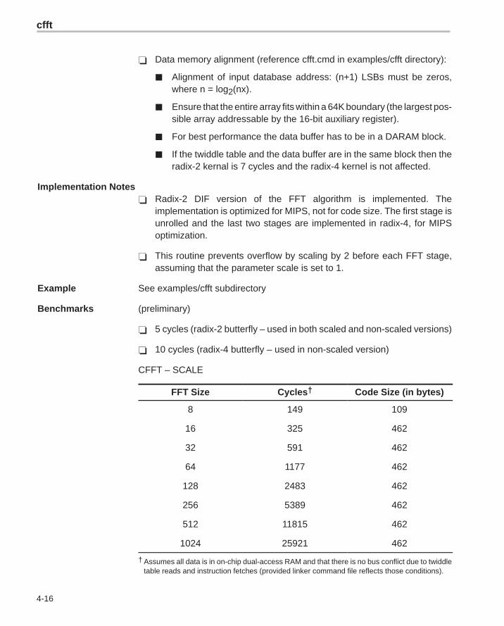
� Data memory alignment (reference cfft.cmd in examples/cfft directory):
� Alignment of input database address: (n+1) LSBs must be zeros,where n = log2(nx).
� Ensure that the entire array fits within a 64K boundary (the largest pos-sible array addressable by the 16-bit auxiliary register).
� For best performance the data buffer has to be in a DARAM block.
� If the twiddle table and the data buffer are in the same block then theradix-2 kernal is 7 cycles and the radix-4 kernel is not affected.
Implementation Notes� Radix-2 DIF version of the FFT algorithm is implemented. The
implementation is optimized for MIPS, not for code size. The first stage isunrolled and the last two stages are implemented in radix-4, for MIPSoptimization.
� This routine prevents overflow by scaling by 2 before each FFT stage,assuming that the parameter scale is set to 1.
Example See examples/cfft subdirectory
Benchmarks (preliminary)
� 5 cycles (radix-2 butterfly – used in both scaled and non-scaled versions)
� 10 cycles (radix-4 butterfly – used in non-scaled version)
CFFT – SCALE
FFT Size Cycles† Code Size (in bytes)
8 149 109
16 325 462
32 591 462
64 1177 462
128 2483 462
256 5389 462
512 11815 462
1024 25921 462
† Assumes all data is in on-chip dual-access RAM and that there is no bus conflict due to twiddletable reads and instruction fetches (provided linker command file reflects those conditions).
cfir
4-17 Function Descriptions
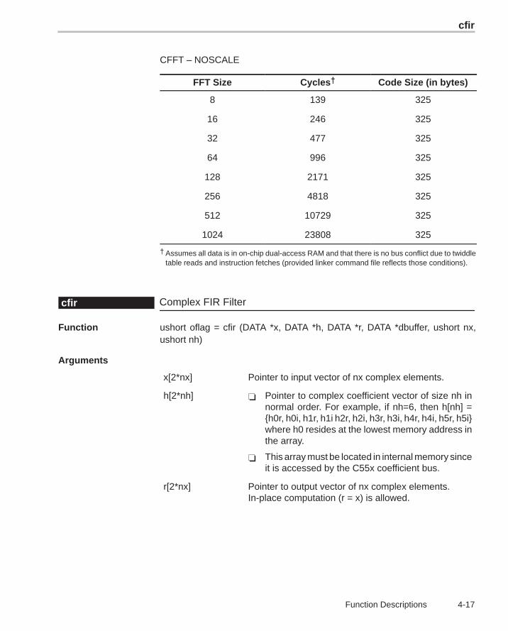
CFFT – NOSCALE
FFT Size Cycles† Code Size (in bytes)
8 139 325
16 246 325
32 477 325
64 996 325
128 2171 325
256 4818 325
512 10729 325
1024 23808 325
† Assumes all data is in on-chip dual-access RAM and that there is no bus conflict due to twiddletable reads and instruction fetches (provided linker command file reflects those conditions).
Complex FIR Filtercfir
Function ushort oflag = cfir (DATA *x, DATA *h, DATA *r, DATA *dbuffer, ushort nx,ushort nh)
Arguments
x[2*nx] Pointer to input vector of nx complex elements.
h[2*nh] � Pointer to complex coefficient vector of size nh innormal order. For example, if nh=6, then h[nh] ={h0r, h0i, h1r, h1i h2r, h2i, h3r, h3i, h4r, h4i, h5r, h5i}where h0 resides at the lowest memory address inthe array.
� This array must be located in internal memory sinceit is accessed by the C55x coefficient bus.
r[2*nx] Pointer to output vector of nx complex elements.In-place computation (r = x) is allowed.
cfir
4-18
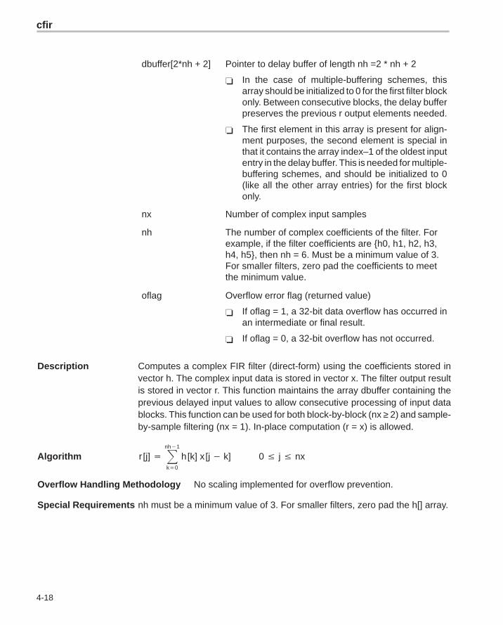
dbuffer[2*nh + 2] Pointer to delay buffer of length nh =2 * nh + 2
� In the case of multiple-buffering schemes, thisarray should be initialized to 0 for the first filter blockonly. Between consecutive blocks, the delay bufferpreserves the previous r output elements needed.
� The first element in this array is present for align-ment purposes, the second element is special inthat it contains the array index–1 of the oldest inputentry in the delay buffer. This is needed for multiple-buffering schemes, and should be initialized to 0(like all the other array entries) for the first blockonly.
nx Number of complex input samples
nh The number of complex coefficients of the filter. Forexample, if the filter coefficients are {h0, h1, h2, h3,h4, h5}, then nh = 6. Must be a minimum value of 3.For smaller filters, zero pad the coefficients to meetthe minimum value.
oflag Overflow error flag (returned value)
� If oflag = 1, a 32-bit data overflow has occurred inan intermediate or final result.
� If oflag = 0, a 32-bit overflow has not occurred.
Description Computes a complex FIR filter (direct-form) using the coefficients stored invector h. The complex input data is stored in vector x. The filter output resultis stored in vector r. This function maintains the array dbuffer containing theprevious delayed input values to allow consecutive processing of input datablocks. This function can be used for both block-by-block (nx ≥ 2) and sample-by-sample filtering (nx = 1). In-place computation (r = x) is allowed.
Algorithm r [j] � �nh�1
k�0
h [k] x [j � k] 0 � j � nx
Overflow Handling Methodology No scaling implemented for overflow prevention.
Special Requirements nh must be a minimum value of 3. For smaller filters, zero pad the h[] array.
cfir
4-19 Function Descriptions
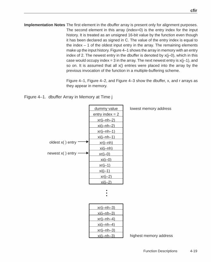
Implementation Notes The first element in the dbuffer array is present only for alignment purposes.The second element in this array (index=0) is the entry index for the inputhistory. It is treated as an unsigned 16-bit value by the function even thoughit has been declared as signed in C. The value of the entry index is equal tothe index – 1 of the oldest input entry in the array. The remaining elementsmake up the input history. Figure 4–1 shows the array in memory with an entryindex of 2. The newest entry in the dbuffer is denoted by x(j–0), which in thiscase would occupy index = 3 in the array. The next newest entry is x(j–1), andso on. It is assumed that all x() entries were placed into the array by theprevious invocation of the function in a multiple-buffering scheme.
Figure 4–1, Figure 4–2, and Figure 4–3 show the dbuffer, x, and r arrays asthey appear in memory.
Figure 4–1. dbuffer Array in Memory at Time j
•••
xr(j–nh–3)xi(j–nh–3)
lowest memory address
highest memory address
oldest x( ) entry
entry index = 2
xr(j–nh–2)xi(j–nh–2)xr(j–nh–1)xi(j–nh–1)xr(j–nh)
xi(j–nh)
dummy value
xr(j–0)xi(j–0)
xr(j–1)xi(j–1)xr(j–2)xi(j–2)
xr(j–nh–4)
xi(j–nh–4)xr(j–nh–3)xi(j–nh–3)
newest x( ) entry
cfir
4-20
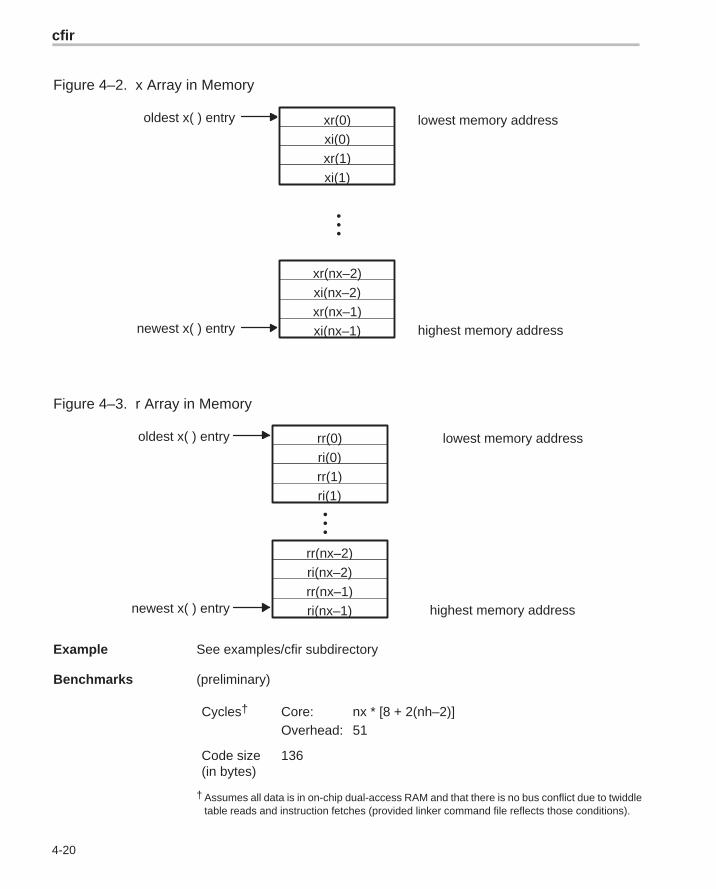
Figure 4–2. x Array in Memory
•••
xr(0)xi(0)
xi(nx–2)xr(nx–2)
lowest memory address
highest memory address
oldest x( ) entry
newest x( ) entryxr(nx–1)xi(nx–1)
xr(1)xi(1)
Figure 4–3. r Array in Memory
•••
ri(0)rr(1)
rr(nx–1)
lowest memory address
highest memory address
oldest x( ) entry
newest x( ) entry
rr(0)
rr(nx–2)ri(nx–2)
ri(nx–1)
ri(1)
Example See examples/cfir subdirectory
Benchmarks (preliminary)
Cycles† Core: nx * [8 + 2(nh–2)]Overhead: 51
Code size(in bytes)
136
† Assumes all data is in on-chip dual-access RAM and that there is no bus conflict due to twiddletable reads and instruction fetches (provided linker command file reflects those conditions).
cifft
4-21 Function Descriptions
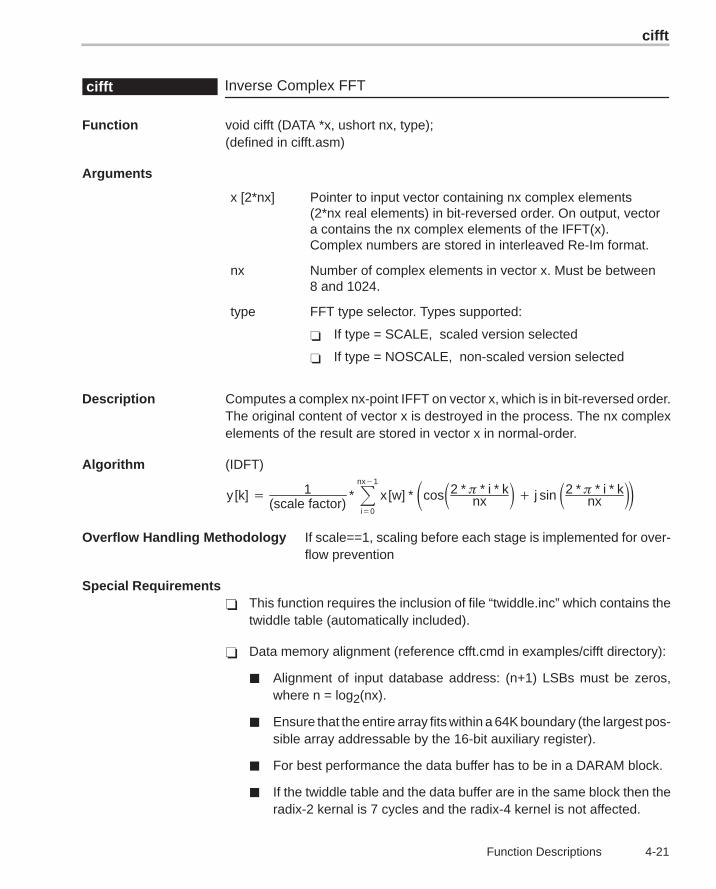
Inverse Complex FFTcifft
Function void cifft (DATA *x, ushort nx, type);(defined in cifft.asm)
Arguments
x [2*nx] Pointer to input vector containing nx complex elements(2*nx real elements) in bit-reversed order. On output, vectora contains the nx complex elements of the IFFT(x).Complex numbers are stored in interleaved Re-Im format.
nx Number of complex elements in vector x. Must be between8 and 1024.
type FFT type selector. Types supported:
� If type = SCALE, scaled version selected
� If type = NOSCALE, non-scaled version selected
Description Computes a complex nx-point IFFT on vector x, which is in bit-reversed order.The original content of vector x is destroyed in the process. The nx complexelements of the result are stored in vector x in normal-order.
Algorithm (IDFT)
y [k] � 1(scale factor)
* �nx�1
i�0
x [w] * �cos�2 * � * i * knx � � j sin �2 * � * i * k
nx ��
Overflow Handling Methodology If scale==1, scaling before each stage is implemented for over-flow prevention
Special Requirements� This function requires the inclusion of file “twiddle.inc” which contains the
twiddle table (automatically included).
� Data memory alignment (reference cfft.cmd in examples/cifft directory):
� Alignment of input database address: (n+1) LSBs must be zeros,where n = log2(nx).
� Ensure that the entire array fits within a 64K boundary (the largest pos-sible array addressable by the 16-bit auxiliary register).
� For best performance the data buffer has to be in a DARAM block.
� If the twiddle table and the data buffer are in the same block then theradix-2 kernal is 7 cycles and the radix-4 kernel is not affected.
cifft
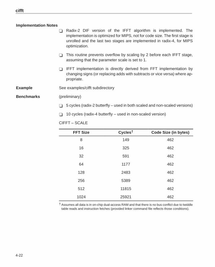
4-22
Implementation Notes� Radix-2 DIF version of the IFFT algorithm is implemented. The
implementation is optimized for MIPS, not for code size. The first stage isunrolled and the last two stages are implemented in radix-4, for MIPSoptimization.
� This routine prevents overflow by scaling by 2 before each IFFT stage,assuming that the parameter scale is set to 1.
� IFFT implementation is directly derived from FFT implementation bychanging signs (or replacing adds with subtracts or vice versa) where ap-propriate.
Example See examples/cifft subdirectory
Benchmarks (preliminary)
� 5 cycles (radix-2 butterfly – used in both scaled and non-scaled versions)
� 10 cycles (radix-4 butterfly – used in non-scaled version)
CIFFT – SCALE
FFT Size Cycles† Code Size (in bytes)
8 149 462
16 325 462
32 591 462
64 1177 462
128 2483 462
256 5389 462
512 11815 462
1024 25921 462
† Assumes all data is in on-chip dual-access RAM and that there is no bus conflict due to twiddletable reads and instruction fetches (provided linker command file reflects those conditions).
convol
4-23 Function Descriptions
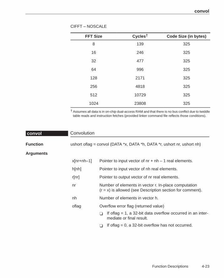
CIFFT – NOSCALE
FFT Size Cycles† Code Size (in bytes)
8 139 325
16 246 325
32 477 325
64 996 325
128 2171 325
256 4818 325
512 10729 325
1024 23808 325
† Assumes all data is in on-chip dual-access RAM and that there is no bus conflict due to twiddletable reads and instruction fetches (provided linker command file reflects those conditions).
Convolutionconvol
Function ushort oflag = convol (DATA *x, DATA *h, DATA *r, ushort nr, ushort nh)
Arguments
x[nr+nh–1] Pointer to input vector of nr + nh – 1 real elements.
h[nh] Pointer to input vector of nh real elements.
r[nr] Pointer to output vector of nr real elements.
nr Number of elements in vector r. In-place computation(r = x) is allowed (see Description section for comment).
nh Number of elements in vector h.
oflag Overflow error flag (returned value)
� If oflag = 1, a 32-bit data overflow occurred in an inter-mediate or final result.
� If oflag = 0, a 32-bit overflow has not occurred.
convol
4-24
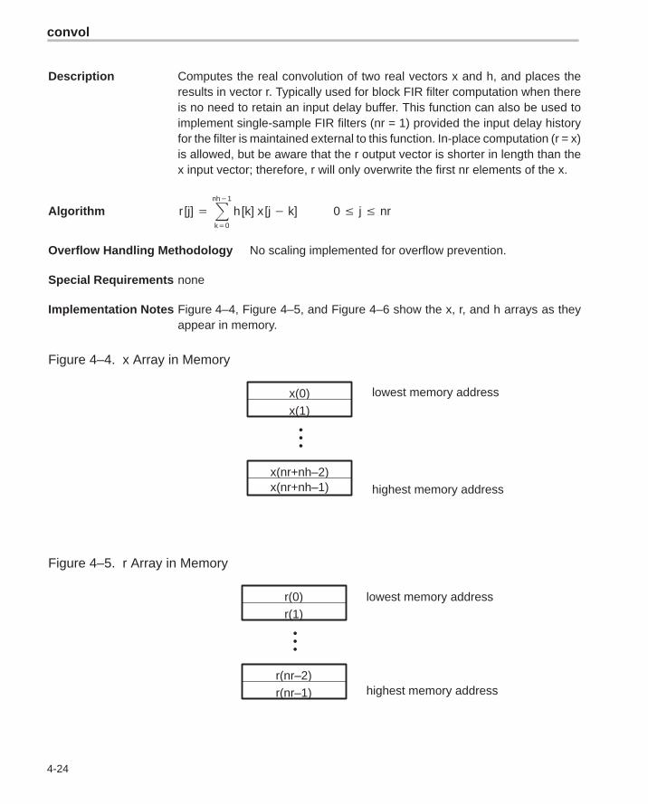
Description Computes the real convolution of two real vectors x and h, and places theresults in vector r. Typically used for block FIR filter computation when thereis no need to retain an input delay buffer. This function can also be used toimplement single-sample FIR filters (nr = 1) provided the input delay historyfor the filter is maintained external to this function. In-place computation (r = x)is allowed, but be aware that the r output vector is shorter in length than thex input vector; therefore, r will only overwrite the first nr elements of the x.
Algorithm r [j] � �nh�1
k�0
h [k] x [j � k] 0 � j � nr
Overflow Handling Methodology No scaling implemented for overflow prevention.
Special Requirements none
Implementation Notes Figure 4–4, Figure 4–5, and Figure 4–6 show the x, r, and h arrays as theyappear in memory.
Figure 4–4. x Array in Memory
•••
x(0)x(1)
x(nr+nh–2)x(nr+nh–1)
lowest memory address
highest memory address
Figure 4–5. r Array in Memory
•••
r(0)r(1)
r(nr–2)r(nr–1)
lowest memory address
highest memory address
convol1
4-25 Function Descriptions
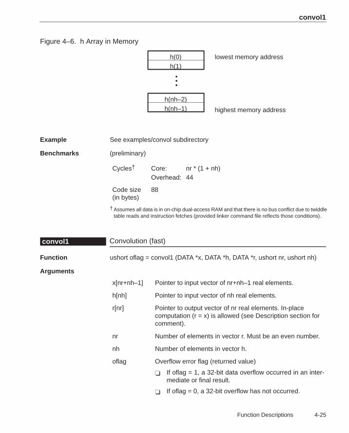
Figure 4–6. h Array in Memory
•••
h(0)h(1)
h(nh–2)h(nh–1)
lowest memory address
highest memory address
Example See examples/convol subdirectory
Benchmarks (preliminary)
Cycles† Core: nr * (1 + nh)Overhead: 44
Code size(in bytes)
88
† Assumes all data is in on-chip dual-access RAM and that there is no bus conflict due to twiddletable reads and instruction fetches (provided linker command file reflects those conditions).
Convolution (fast)convol1
Function ushort oflag = convol1 (DATA *x, DATA *h, DATA *r, ushort nr, ushort nh)
Arguments
x[nr+nh–1] Pointer to input vector of nr+nh–1 real elements.
h[nh] Pointer to input vector of nh real elements.
r[nr] Pointer to output vector of nr real elements. In-placecomputation (r = x) is allowed (see Description section forcomment).
nr Number of elements in vector r. Must be an even number.
nh Number of elements in vector h.
oflag Overflow error flag (returned value)
� If oflag = 1, a 32-bit data overflow occurred in an inter-mediate or final result.
� If oflag = 0, a 32-bit overflow has not occurred.
convol1
4-26
Description Computes the real convolution of two real vectors x and h, and places theresults in vector r. This function utilizes the dual-MAC capability of the C55xto process in parallel two output samples for each iteration of the inner functionloop. It is, therefore, roughly twice as fast as CONVOL, which implements onlya single-MAC approach. However, the number of output samples (nr) must beeven. Typically used for block FIR filter computation when there is no need toretain an input delay buffer. This function can also be used to implement single-sample FIR filters (nr = 1) provided the input delay history for the filter is main-tained external to this function. In-place computation (r = x) is allowed, but beaware that the r output vector is shorter in length than the x input vector; there-fore, r will only overwrite the first nr elements of the x.
Algorithm r [j] � �nh�1
k�0
h [k] x [j � k] 0 � j � nr
Overflow Handling Methodology No scaling implemented for overflow prevention.
Special Requirements� nr must be an even value.
� The vector h[nh] must be located in internal memory since it is accessedusing the C55x coefficient bus, and that bus does not have access to exter-nal memory.
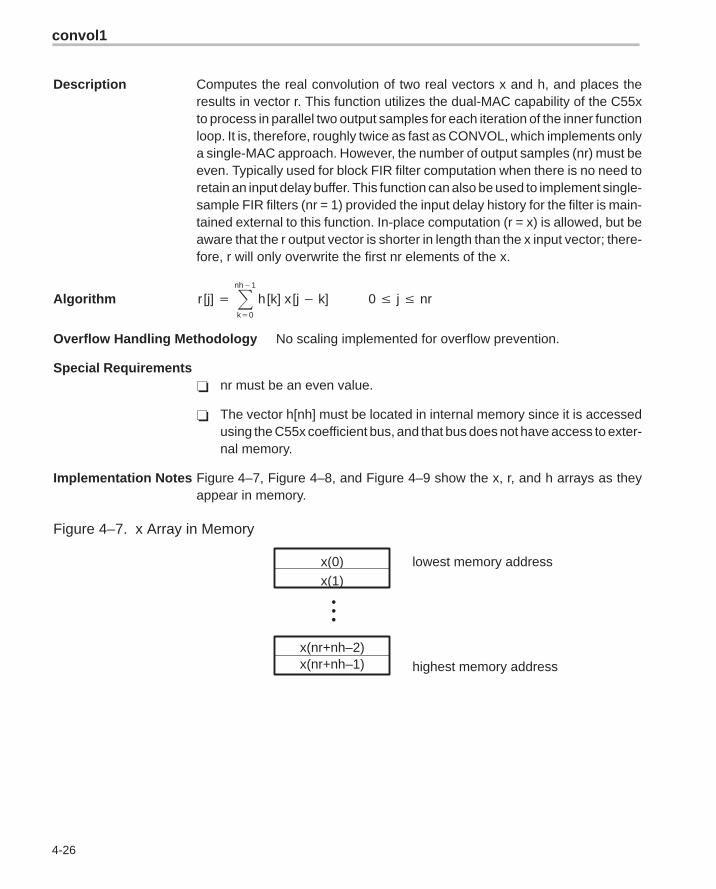
Implementation Notes Figure 4–7, Figure 4–8, and Figure 4–9 show the x, r, and h arrays as theyappear in memory.
Figure 4–7. x Array in Memory
•••
x(0)x(1)
x(nr+nh–2)x(nr+nh–1)
lowest memory address
highest memory address
convol2
4-27 Function Descriptions
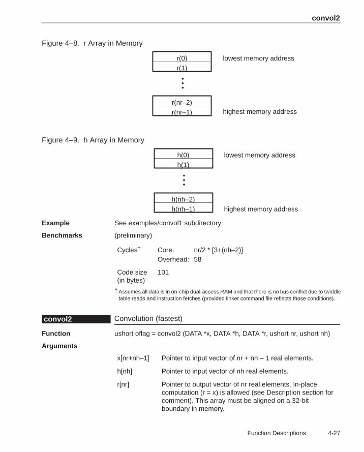
Figure 4–8. r Array in Memory
•••
r(0)r(1)
r(nr–2)r(nr–1)
lowest memory address
highest memory address
Figure 4–9. h Array in Memory
•••
h(0)h(1)
h(nh–2)h(nh–1)
lowest memory address
highest memory address
Example See examples/convol1 subdirectory
Benchmarks (preliminary)
Cycles† Core: nr/2 * [3+(nh–2)]Overhead: 58
Code size(in bytes)
101
† Assumes all data is in on-chip dual-access RAM and that there is no bus conflict due to twiddletable reads and instruction fetches (provided linker command file reflects those conditions).
Convolution (fastest)convol2
Function ushort oflag = convol2 (DATA *x, DATA *h, DATA *r, ushort nr, ushort nh)
Arguments
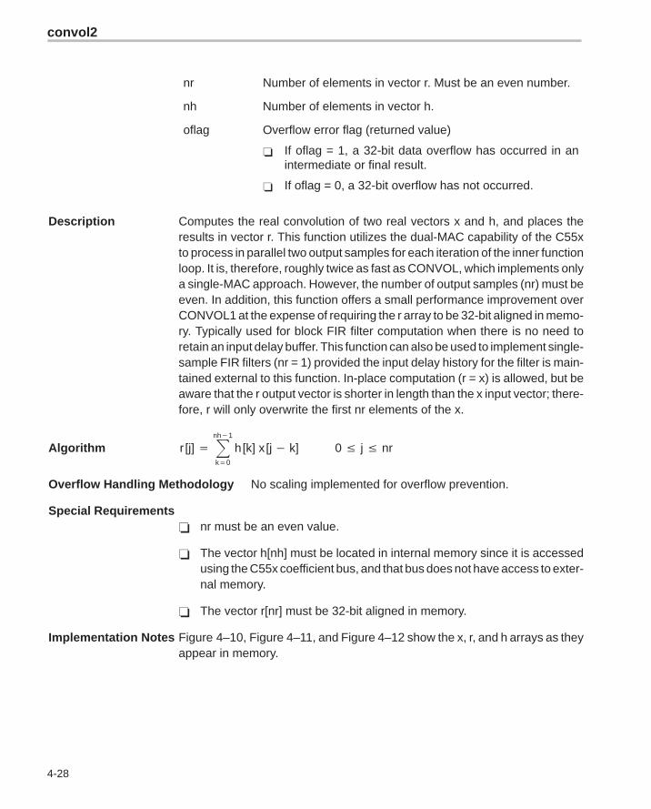
x[nr+nh–1] Pointer to input vector of nr + nh – 1 real elements.
h[nh] Pointer to input vector of nh real elements.
r[nr] Pointer to output vector of nr real elements. In-placecomputation (r = x) is allowed (see Description section forcomment). This array must be aligned on a 32-bitboundary in memory.
convol2
4-28
nr Number of elements in vector r. Must be an even number.
nh Number of elements in vector h.
oflag Overflow error flag (returned value)
� If oflag = 1, a 32-bit data overflow has occurred in anintermediate or final result.
� If oflag = 0, a 32-bit overflow has not occurred.
Description Computes the real convolution of two real vectors x and h, and places theresults in vector r. This function utilizes the dual-MAC capability of the C55xto process in parallel two output samples for each iteration of the inner functionloop. It is, therefore, roughly twice as fast as CONVOL, which implements onlya single-MAC approach. However, the number of output samples (nr) must beeven. In addition, this function offers a small performance improvement overCONVOL1 at the expense of requiring the r array to be 32-bit aligned in memo-ry. Typically used for block FIR filter computation when there is no need toretain an input delay buffer. This function can also be used to implement single-sample FIR filters (nr = 1) provided the input delay history for the filter is main-tained external to this function. In-place computation (r = x) is allowed, but beaware that the r output vector is shorter in length than the x input vector; there-fore, r will only overwrite the first nr elements of the x.
Algorithm r [j] � �nh�1
k�0
h [k] x [j � k] 0 � j � nr
Overflow Handling Methodology No scaling implemented for overflow prevention.
Special Requirements� nr must be an even value.
� The vector h[nh] must be located in internal memory since it is accessedusing the C55x coefficient bus, and that bus does not have access to exter-nal memory.
� The vector r[nr] must be 32-bit aligned in memory.
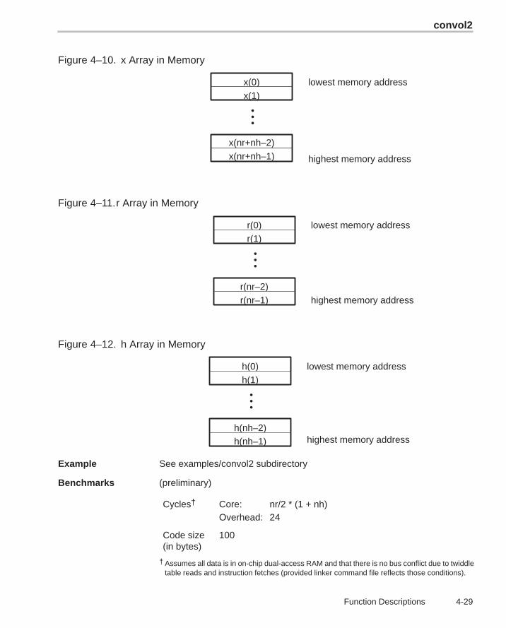
Implementation Notes Figure 4–10, Figure 4–11, and Figure 4–12 show the x, r, and h arrays as theyappear in memory.
convol2
4-29 Function Descriptions
Figure 4–10. x Array in Memory
•••
x(0)x(1)
x(nr+nh–2)x(nr+nh–1)
lowest memory address
highest memory address
Figure 4–11.r Array in Memory
•••
r(0)r(1)
r(nr–2)r(nr–1)
lowest memory address
highest memory address
Figure 4–12. h Array in Memory
•••
h(0)h(1)
h(nh–2)h(nh–1)
lowest memory address
highest memory address
Example See examples/convol2 subdirectory
Benchmarks (preliminary)
Cycles† Core: nr/2 * (1 + nh)Overhead: 24
Code size(in bytes)
100
† Assumes all data is in on-chip dual-access RAM and that there is no bus conflict due to twiddletable reads and instruction fetches (provided linker command file reflects those conditions).
corr
4-30
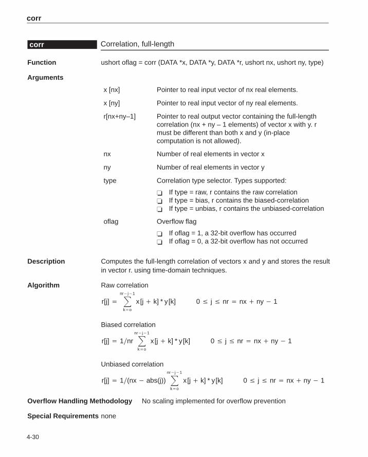
Correlation, full-lengthcorr
Function ushort oflag = corr (DATA *x, DATA *y, DATA *r, ushort nx, ushort ny, type)
Arguments
x [nx] Pointer to real input vector of nx real elements.
x [ny] Pointer to real input vector of ny real elements.
r[nx+ny–1] Pointer to real output vector containing the full-lengthcorrelation (nx + ny – 1 elements) of vector x with y. rmust be different than both x and y (in-placecomputation is not allowed).
nx Number of real elements in vector x
ny Number of real elements in vector y
type Correlation type selector. Types supported:
� If type = raw, r contains the raw correlation� If type = bias, r contains the biased-correlation� If type = unbias, r contains the unbiased-correlation
oflag Overflow flag
� If oflag = 1, a 32-bit overflow has occurred� If oflag = 0, a 32-bit overflow has not occurred
Description Computes the full-length correlation of vectors x and y and stores the resultin vector r. using time-domain techniques.
Algorithm Raw correlation
r[j] � �nr�j�1
k�o
x [j � k] * y [k] 0 � j � nr � nx � ny � 1
Biased correlation
r[j] � 1nr �nr�j�1
k�o
x [j � k] * y [k] 0 � j � nr � nx � ny � 1
Unbiased correlation
r[j] � 1(nx � abs(j)) �nr�j�1
k�o
x [j � k] * y [k] 0 � j � nr � nx � ny � 1
Overflow Handling Methodology No scaling implemented for overflow prevention
Special Requirements none
dlms
4-31 Function Descriptions
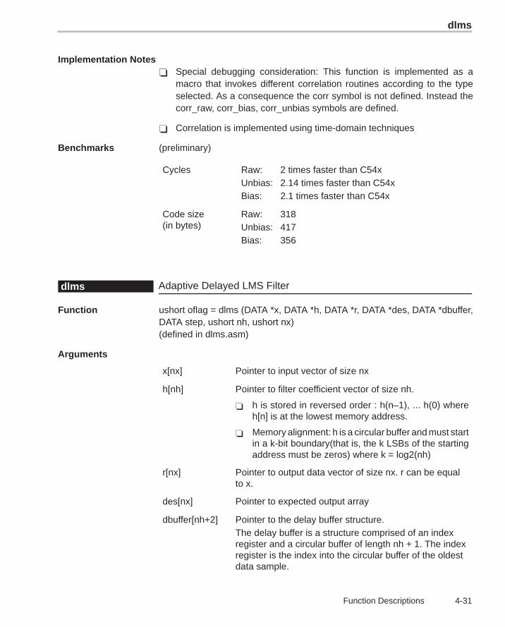
Implementation Notes� Special debugging consideration: This function is implemented as a
macro that invokes different correlation routines according to the typeselected. As a consequence the corr symbol is not defined. Instead thecorr_raw, corr_bias, corr_unbias symbols are defined.
� Correlation is implemented using time-domain techniques
Benchmarks (preliminary)
Cycles Raw: 2 times faster than C54xUnbias: 2.14 times faster than C54xBias: 2.1 times faster than C54x
Code size (in bytes)
Raw: 318Unbias: 417Bias: 356
Adaptive Delayed LMS Filterdlms
Function ushort oflag = dlms (DATA *x, DATA *h, DATA *r, DATA *des, DATA *dbuffer,DATA step, ushort nh, ushort nx)(defined in dlms.asm)
Arguments
x[nx] Pointer to input vector of size nx
h[nh] Pointer to filter coefficient vector of size nh.
� h is stored in reversed order : h(n–1), ... h(0) whereh[n] is at the lowest memory address.
� Memory alignment: h is a circular buffer and must startin a k-bit boundary(that is, the k LSBs of the startingaddress must be zeros) where k = log2(nh)
r[nx] Pointer to output data vector of size nx. r can be equalto x.
des[nx] Pointer to expected output array
dbuffer[nh+2] Pointer to the delay buffer structure.The delay buffer is a structure comprised of an indexregister and a circular buffer of length nh + 1. The indexregister is the index into the circular buffer of the oldestdata sample.
dlms
4-32
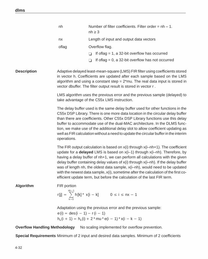
nh Number of filter coefficients. Filter order = nh – 1.nh ≥ 3
nx Length of input and output data vectors
oflag Overflow flag.
� If oflag = 1, a 32-bit overflow has occurred
� If oflag = 0, a 32-bit overflow has not occurred
Description Adaptive delayed least-mean-square (LMS) FIR filter using coefficients storedin vector h. Coefficients are updated after each sample based on the LMSalgorithm and using a constant step = 2*mu. The real data input is stored invector dbuffer. The filter output result is stored in vector r .
LMS algorithm uses the previous error and the previous sample (delayed) totake advantage of the C55x LMS instruction.
The delay buffer used is the same delay buffer used for other functions in theC55x DSP Library. There is one more data location in the circular delay bufferthan there are coefficients. Other C55x DSP Library functions use this delaybuffer to accommodate use of the dual-MAC architecture. In the DLMS func-tion, we make use of the additional delay slot to allow coefficient updating aswell as FIR calculation without a need to update the circular buffer in the interimoperations.
The FIR output calculation is based on x(i) through x(i–nh+1). The coefficientupdate for a delayed LMS is based on x(i–1) through x(i–nh). Therefore, byhaving a delay buffer of nh+1, we can perform all calculations with the givendelay buffer containing delay values of x(i) through x(i–nh). If the delay bufferwas of length nh, the oldest data sample, x(i–nh), would need to be updatedwith the newest data sample, x(i), sometime after the calculation of the first co-efficient update term, but before the calculation of the last FIR term.
Algorithm FIR portion
r [j] � �nh�1
k�0
h [k] * x [i � k] 0 � i � nx � 1
Adaptation using the previous error and the previous sample:e (i)� des (i � 1)� r (i � 1)hk (i � 1)� hk (i)� 2 * mu * e(i � 1) * x(i � k � 1)
Overflow Handling Methodology No scaling implemented for overflow prevention.
Special Requirements Minimum of 2 input and desired data samples. Minimum of 2 coefficients
expn
4-33 Function Descriptions
Implementation Notes� Delayed version implemented to take advantage of the C55x LMS instruc-
tion.
� Effect of using delayed error signal on convergence minimum: For reference, following is the algorithm for the regular LMS (non-delayed):
FIR portion
r [j] � �nh�1
k�0
h [k] * x [i � k] 0 � i � nx � 1
Adaptation using the current error and the current sample:e (i) � des (i)� r (i)hk (i � 1)� hk (i)� 2 * mu * e(i) * x(i � k)
Example See examples/dlms subdirectory
Benchmarks (preliminary)
Cycles† Core: nx * (7 + 2*(nh – 1)) = nx * (5 + 2 * nh)Overhead: 26
Code size(in bytes)
122
† Assumes all data is in on-chip dual-access RAM and that there is no bus conflict due to twiddletable reads and instruction fetches (provided linker command file reflects those conditions).
Exponential Base eexpn
Function ushort oflag = expn (DATA *x, DATA *r, ushort nx)(defined in expn.asm)
Arguments
x[nx] Pointer to input vector of size nx. x contains the numbersnormalized between (–1,1) in q15 format
r[nx] Pointer to output data vector (Q3.12 format) of size nx. r canbe equal to x.
nx Length of input and output data vectors
oflag Overflow flag.
� If oflag = 1, a 32-bit overflow has occurred
� If oflag = 0, a 32-bit overflow has not occurred
fir
4-34
Description Computes the exponent of elements of vector x using Taylor series.
Algorithm for (i � 0; i � nx; i ��) y(i) � ex(i) where –1 � x(i) � 1
Overflow Handling Methodology Not applicable
Special Requirements Linker command file: you must allocate .data section (for polynomial coeffi-cients)
Implementation Notes Computes the exponent of elements of vector x. It uses the following Taylorseries:exp(x) � c0 � (c1 * x) � (c2 * x2) � (c3 * x3) � (c4 * x4) � (c5 * x5)
wherec0 = 1.0000c1 = 1.0001c2 = 0.4990c3 = 0.1705c4 = 0.0348c5 = 0.0139
Example See examples/expn subdirectory
Benchmarks (preliminary)
Cycles† Core: 11 * nxOverhead: 18
Code size(in bytes)
57
† Assumes all data is in on-chip dual-access RAM and that there is no bus conflict due to twiddletable reads and instruction fetches (provided linker command file reflects those conditions).
FIR Filterfir
Function ushort oflag = fir (DATA *x, DATA *h, DATA *r, DATA *dbuffer, ushort nx,ushort nh)
Arguments
x[nx] Pointer to input vector of nx real elements.
h[nh] � Pointer to coefficient vector of size nh in normal order.For example, if nh=6, then h[nh] = {h0, h1, h2, h3, h4,h5} where h0 resides at the lowest memory addressin the array.
� This array must be located in internal memory sinceit is accessed by the C55x coefficient bus.
fir
4-35 Function Descriptions
r[nx] Pointer to output vector of nx real elements. In-placecomputation (r = x) is allowed.
dbuffer[nh+2] Pointer to delay buffer of length nh = nh + 2
� In the case of multiple-buffering schemes, this arrayshould be initialized to 0 for the first filter block only.Between consecutive blocks, the delay buffer pre-serves the previous r output elements needed.
� The first element in this array is special in that it con-tains the array index–1 of the oldest input entry in thedelay buffer. This is needed for multiple-bufferingschemes, and should be initialized to 0 (like all the oth-er array entries) for the first block only.
nx Number of input samples
nh The number of coefficients of the filter. For example, ifthe filter coefficients are {h0, h1, h2, h3, h4, h5}, then nh= 6. Must be a minimum value of 3. For smaller filters,zero pad the coefficients to meet the minimum value.
oflag Overflow error flag (returned value)
� If oflag = 1, a 32-bit data overflow occurred in an inter-mediate or final result.
� If oflag = 0, a 32-bit overflow has not occurred.
Description Computes a real FIR filter (direct-form) using the coefficients stored in vectorh. The real input data is stored in vector x. The filter output result is stored invector r. This function maintains the array dbuffer containing the previousdelayed input values to allow consecutive processing of input data blocks. Thisfunction can be used for both block-by-block (nx ≥ 2) and sample-by-samplefiltering (nx = 1). In place computation (r = x) is allowed.
Algorithm r [j] � �nh�1
k�0
h [k] x [j � k] 0 � j � nx
Overflow Handling Methodology No scaling implemented for overflow prevention.
Special Requirements nh must be a minimum value of 3. For smaller filters, zero pad the h[] array.
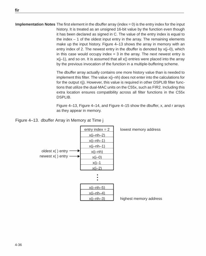
fir
4-36
Implementation Notes The first element in the dbuffer array (index = 0) is the entry index for the inputhistory. It is treated as an unsigned 16-bit value by the function even thoughit has been declared as signed in C. The value of the entry index is equal tothe index – 1 of the oldest input entry in the array. The remaining elementsmake up the input history. Figure 4–13 shows the array in memory with anentry index of 2. The newest entry in the dbuffer is denoted by x(j–0), whichin this case would occupy index = 3 in the array. The next newest entry isx(j–1), and so on. It is assumed that all x() entries were placed into the arrayby the previous invocation of the function in a multiple-buffering scheme.
The dbuffer array actually contains one more history value than is needed toimplement this filter. The value x(j–nh) does not enter into the calculations forfor the output r(j). However, this value is required in other DSPLIB filter func-tions that utilize the dual-MAC units on the C55x, such as FIR2. Including thisextra location ensures compatibility across all filter functions in the C55xDSPLIB.
Figure 4–13, Figure 4–14, and Figure 4–15 show the dbuffer, x, and r arraysas they appear in memory.
Figure 4–13. dbuffer Array in Memory at Time j
•••
x(j–nh–5)
lowest memory address
highest memory address
oldest x( ) entry
entry index = 2
x(j–nh–2)x(j–nh–1)x(j–nh–1)
x(j–nh)x(j–0)x(j–1)x(j–2)
x(j–nh–4)x(j–nh–3)
newest x( ) entry
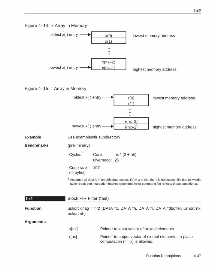
fir2
4-37 Function Descriptions
Figure 4–14. x Array in Memory
•••
x(0)
x(nx–2)
lowest memory address
highest memory address
oldest x( ) entry
newest x( ) entry x(nx–1)
x(1)
Figure 4–15. r Array in Memory
•••
r(nx–1)
lowest memory address
highest memory address
oldest x( ) entry
newest x( ) entry
r(0)
r(nx–2)
r(1)
Example See examples/fir subdirectory
Benchmarks (preliminary)
Cycles† Core: nx * (2 + nh)Overhead: 25
Code size(in bytes)
107
† Assumes all data is in on-chip dual-access RAM and that there is no bus conflict due to twiddletable reads and instruction fetches (provided linker command file reflects those conditions).
Block FIR Filter (fast)fir2
Function ushort oflag = fir2 (DATA *x, DATA *h, DATA *r, DATA *dbuffer, ushort nx,ushort nh)
Arguments
x[nx] Pointer to input vector of nx real elements.
r[nx] Pointer to output vector of nx real elements. In-placecomputation (r = x) is allowed.
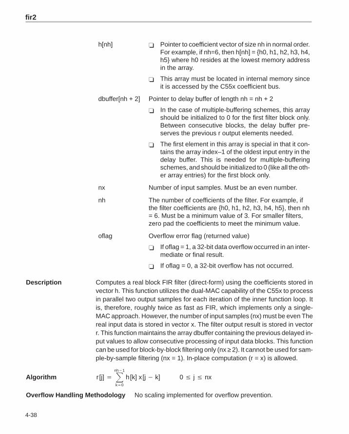
fir2
4-38
h[nh] � Pointer to coefficient vector of size nh in normal order.For example, if nh=6, then h[nh] = {h0, h1, h2, h3, h4,h5} where h0 resides at the lowest memory addressin the array.
� This array must be located in internal memory sinceit is accessed by the C55x coefficient bus.
dbuffer[nh + 2] Pointer to delay buffer of length nh = nh + 2
� In the case of multiple-buffering schemes, this arrayshould be initialized to 0 for the first filter block only.Between consecutive blocks, the delay buffer pre-serves the previous r output elements needed.
� The first element in this array is special in that it con-tains the array index–1 of the oldest input entry in thedelay buffer. This is needed for multiple-bufferingschemes, and should be initialized to 0 (like all the oth-er array entries) for the first block only.
nx Number of input samples. Must be an even number.
nh The number of coefficients of the filter. For example, ifthe filter coefficients are {h0, h1, h2, h3, h4, h5}, then nh= 6. Must be a minimum value of 3. For smaller filters,zero pad the coefficients to meet the minimum value.
oflag Overflow error flag (returned value)
� If oflag = 1, a 32-bit data overflow occurred in an inter-mediate or final result.
� If oflag = 0, a 32-bit overflow has not occurred.
Description Computes a real block FIR filter (direct-form) using the coefficients stored invector h. This function utilizes the dual-MAC capability of the C55x to processin parallel two output samples for each iteration of the inner function loop. Itis, therefore, roughly twice as fast as FIR, which implements only a single-MAC approach. However, the number of input samples (nx) must be even Thereal input data is stored in vector x. The filter output result is stored in vectorr. This function maintains the array dbuffer containing the previous delayed in-put values to allow consecutive processing of input data blocks. This functioncan be used for block-by-block filtering only (nx ≥ 2). It cannot be used for sam-ple-by-sample filtering (nx = 1). In-place computation (r = x) is allowed.
Algorithm r [j] � �nh�1
k�0
h [k] x [j � k] 0 � j � nx
Overflow Handling Methodology No scaling implemented for overflow prevention.
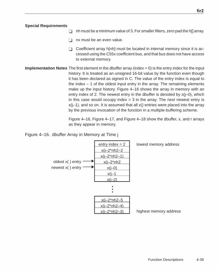
fir2
4-39 Function Descriptions
Special Requirements� nh must be a minimum value of 3. For smaller filters, zero pad the h[] array.
� nx must be an even value.
� Coefficient array h[nh] must be located in internal memory since it is ac-cessed using the C55x coefficient bus, and that bus does not have accessto external memory.
Implementation Notes The first element in the dbuffer array (index = 0) is the entry index for the inputhistory. It is treated as an unsigned 16-bit value by the function even thoughit has been declared as signed in C. The value of the entry index is equal tothe index – 1 of the oldest input entry in the array. The remaining elementsmake up the input history. Figure 4–16 shows the array in memory with anentry index of 2. The newest entry in the dbuffer is denoted by x(j–0), whichin this case would occupy index = 3 in the array. The next newest entry isx(j–1), and so on. It is assumed that all x() entries were placed into the arrayby the previous invocation of the function in a multiple-buffering scheme.
Figure 4–16, Figure 4–17, and Figure 4–18 show the dbuffer, x, and r arraysas they appear in memory.
Figure 4–16. dbuffer Array in Memory at Time j
•••
x(j–2*nh2–5)
lowest memory address
highest memory address
oldest x( ) entry
entry index = 2
x(j–2*nh2–2)x(j–2*nh2–1)
x(j–2*nh2)x(j–0)
x(j–1)x(j–2)
x(j–2*nh2–4)x(j–2*nh2–3)
newest x( ) entry
firdec
4-40
Figure 4–17. x Array in Memory
•••
x(0)
x(nx–2)
lowest memory address
highest memory address
oldest x( ) entry
newest x( ) entry x(nx–1)
x(1)
Figure 4–18. r Array in Memory
•••
r(nx–1)
lowest memory address
highest memory address
oldest x( ) entry
newest x( ) entry
r(0)
r(nx–2)
r(1)
Example See examples/fir2 subdirectory
Benchmarks (preliminary)
Cycles† Core: (nx/2) * [5+(nh–3)]Overhead: 32
Code size(in bytes)
134
† Assumes all data is in on-chip dual-access RAM and that there is no bus conflict due to twiddletable reads and instruction fetches (provided linker command file reflects those conditions).
Decimating FIR Filterfirdec
Function ushort oflag = firdec (DATA *x, DATA *h, DATA *r, DATA *dbuffer , ushort nh,ushort nx, ushort D)(defined in decimate.asm)
Arguments
x [nx] Pointer to real input vector of nx real elements.
h[nh] Pointer to coefficient vector of size nh in normal order:H = b0 b1 b2 b3 …
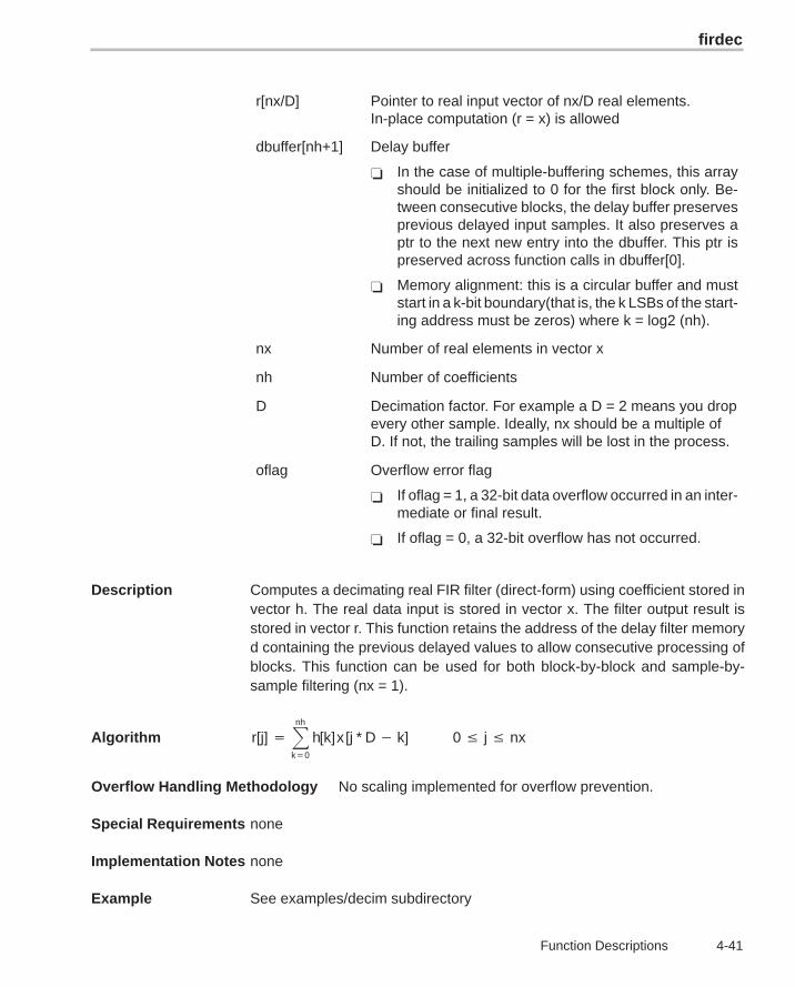
firdec
4-41 Function Descriptions
r[nx/D] Pointer to real input vector of nx/D real elements.In-place computation (r = x) is allowed
dbuffer[nh+1] Delay buffer
� In the case of multiple-buffering schemes, this arrayshould be initialized to 0 for the first block only. Be-tween consecutive blocks, the delay buffer preservesprevious delayed input samples. It also preserves aptr to the next new entry into the dbuffer. This ptr ispreserved across function calls in dbuffer[0].
� Memory alignment: this is a circular buffer and muststart in a k-bit boundary(that is, the k LSBs of the start-ing address must be zeros) where k = log2 (nh).
nx Number of real elements in vector x
nh Number of coefficients
D Decimation factor. For example a D = 2 means you dropevery other sample. Ideally, nx should be a multiple ofD. If not, the trailing samples will be lost in the process.
oflag Overflow error flag
� If oflag = 1, a 32-bit data overflow occurred in an inter-mediate or final result.
� If oflag = 0, a 32-bit overflow has not occurred.
Description Computes a decimating real FIR filter (direct-form) using coefficient stored invector h. The real data input is stored in vector x. The filter output result isstored in vector r. This function retains the address of the delay filter memoryd containing the previous delayed values to allow consecutive processing ofblocks. This function can be used for both block-by-block and sample-by-sample filtering (nx = 1).
Algorithm r[j] ��nh
k�0
h[k]x [j * D � k] 0 � j � nx
Overflow Handling Methodology No scaling implemented for overflow prevention.
Special Requirements none
Implementation Notes none
Example See examples/decim subdirectory
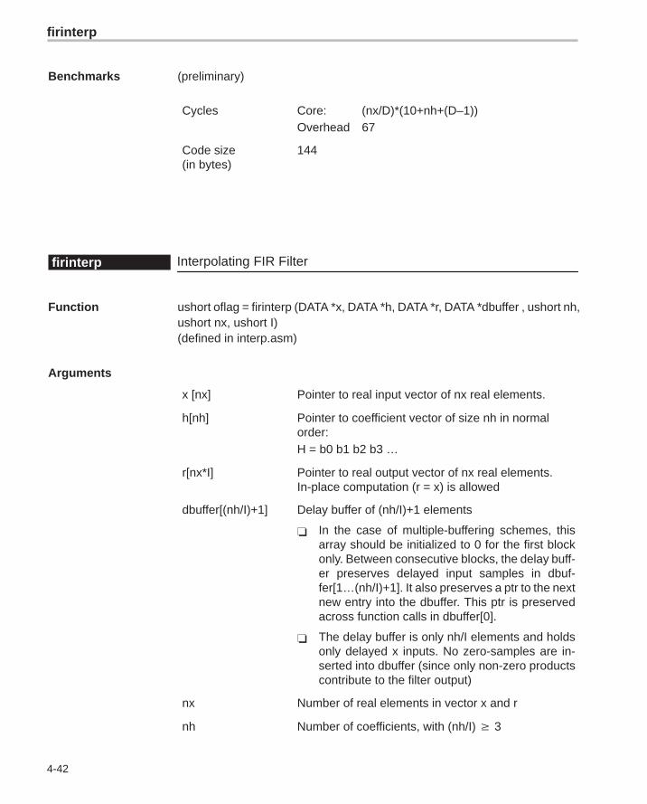
firinterp
4-42
Benchmarks (preliminary)
Cycles Core: (nx/D)*(10+nh+(D–1))Overhead 67
Code size(in bytes)
144
Interpolating FIR Filterfirinterp
Function ushort oflag = firinterp (DATA *x, DATA *h, DATA *r, DATA *dbuffer , ushort nh,ushort nx, ushort I)(defined in interp.asm)
Arguments
x [nx] Pointer to real input vector of nx real elements.
h[nh] Pointer to coefficient vector of size nh in normalorder:H = b0 b1 b2 b3 …
r[nx*I] Pointer to real output vector of nx real elements.In-place computation (r = x) is allowed
dbuffer[(nh/I)+1] Delay buffer of (nh/I)+1 elements
� In the case of multiple-buffering schemes, thisarray should be initialized to 0 for the first blockonly. Between consecutive blocks, the delay buff-er preserves delayed input samples in dbuf-fer[1…(nh/I)+1]. It also preserves a ptr to the nextnew entry into the dbuffer. This ptr is preservedacross function calls in dbuffer[0].
� The delay buffer is only nh/I elements and holdsonly delayed x inputs. No zero-samples are in-serted into dbuffer (since only non-zero productscontribute to the filter output)
nx Number of real elements in vector x and r
nh Number of coefficients, with (nh/I) 3
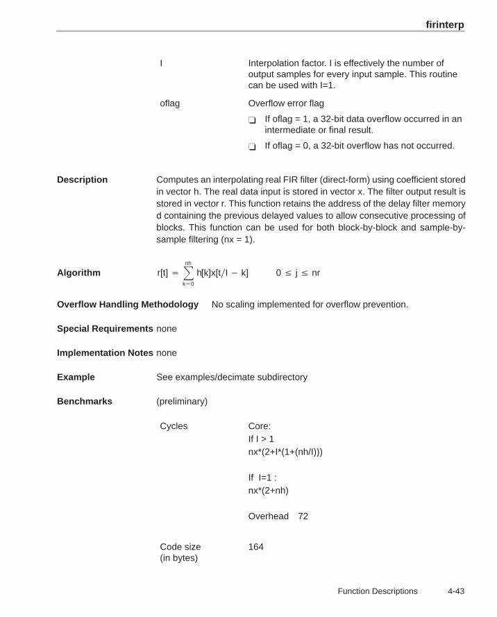
firinterp
4-43 Function Descriptions
I Interpolation factor. I is effectively the number ofoutput samples for every input sample. This routinecan be used with I=1.
oflag Overflow error flag
� If oflag = 1, a 32-bit data overflow occurred in anintermediate or final result.
� If oflag = 0, a 32-bit overflow has not occurred.
Description Computes an interpolating real FIR filter (direct-form) using coefficient storedin vector h. The real data input is stored in vector x. The filter output result isstored in vector r. This function retains the address of the delay filter memoryd containing the previous delayed values to allow consecutive processing ofblocks. This function can be used for both block-by-block and sample-by-sample filtering (nx = 1).
Algorithm r[t] ��nh
k�0
h[k]x[tI � k] 0 � j � nr
Overflow Handling Methodology No scaling implemented for overflow prevention.
Special Requirements none
Implementation Notes none
Example See examples/decimate subdirectory
Benchmarks (preliminary)
Cycles Core:If I > 1nx*(2+I*(1+(nh/I)))
If I=1 :nx*(2+nh)
Overhead 72
Code size (in bytes)
164
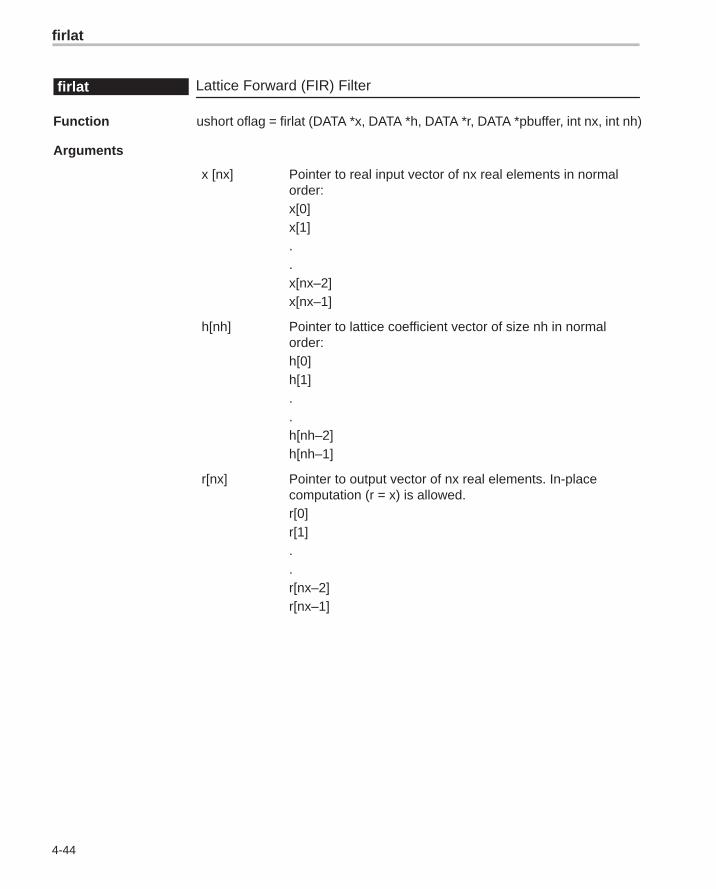
firlat
4-44
Lattice Forward (FIR) Filterfirlat
Function ushort oflag = firlat (DATA *x, DATA *h, DATA *r, DATA *pbuffer, int nx, int nh)
Arguments
x [nx] Pointer to real input vector of nx real elements in normalorder:x[0]x[1]..x[nx–2]x[nx–1]
h[nh] Pointer to lattice coefficient vector of size nh in normalorder:h[0]h[1]..h[nh–2]h[nh–1]
r[nx] Pointer to output vector of nx real elements. In-placecomputation (r = x) is allowed.r[0]r[1]..r[nx–2]r[nx–1]
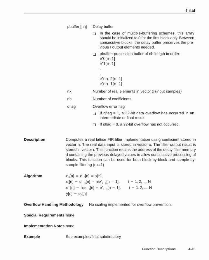
firlat
4-45 Function Descriptions
pbuffer [nh] Delay buffer
� In the case of multiple-buffering schemes, this arrayshould be initialized to 0 for the first block only. Betweenconsecutive blocks, the delay buffer preserves the pre-vious r output elements needed.
� pbuffer: procession buffer of nh length in order:e′0[n–1]e′1[n–1]..e′nh–2[n–1]e′nh–1[n–1]
nx Number of real elements in vector x (input samples)
nh Number of coefficients
oflag Overflow error flag
� If oflag = 1, a 32-bit data overflow has occurred in anintermediate or final result
� If oflag = 0, a 32-bit overflow has not occurred.
Description Computes a real lattice FIR filter implementation using coefficient stored invector h. The real data input is stored in vector x. The filter output result isstored in vector r. This function retains the address of the delay filter memoryd containing the previous delayed values to allow consecutive processing ofblocks. This function can be used for both block-by-block and sample-by-sample filtering (nx=1)
Algorithm e0[n] � e�0[n] � x[n],
ei[n] � ei�1[n] � hie�i�1[n � 1], i � 1, 2, ��� , N
e�i[n] � hiei�1[n] � e�i�1[n � 1], i � 1, 2, ��� , N
y[n] � eN[n]
Overflow Handling Methodology No scaling implemented for overflow prevention.
Special Requirements none
Implementation Notes none
Example See examples/firlat subdirectory
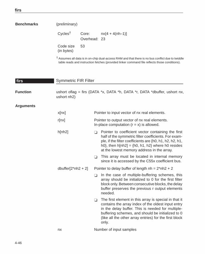
firs
4-46
Benchmarks (preliminary)
Cycles† Core: nx{4 + 4(nh–1)]Overhead: 23
Code size(in bytes)
53
† Assumes all data is in on-chip dual-access RAM and that there is no bus conflict due to twiddletable reads and instruction fetches (provided linker command file reflects those conditions).
Symmetric FIR Filterfirs
Function ushort oflag = firs (DATA *x, DATA *h, DATA *r, DATA *dbuffer, ushort nx,ushort nh2)
Arguments
x[nx] Pointer to input vector of nx real elements.
r[nx] Pointer to output vector of nx real elements.In-place computation (r = x) is allowed.
h[nh2] � Pointer to coefficient vector containing the firsthalf of the symmetric filter coefficients. For exam-ple, if the filter coefficients are {h0, h1, h2, h2, h1,h0}, then h[nh2] = {h0, h1, h2} where h0 residesat the lowest memory address in the array.
� This array must be located in internal memorysince it is accessed by the C55x coefficient bus.
dbuffer[2*nh2 + 2] Pointer to delay buffer of length nh = 2*nh2 + 2
� In the case of multiple-buffering schemes, thisarray should be initialized to 0 for the first filterblock only. Between consecutive blocks, the delaybuffer preserves the previous r output elementsneeded.
� The first element in this array is special in that itcontains the array index of the oldest input entryin the delay buffer. This is needed for multiple-buffering schemes, and should be initialized to 0(like all the other array entries) for the first blockonly.
nx Number of input samples
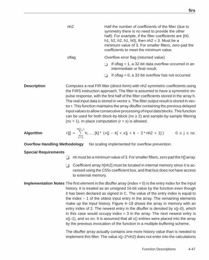
firs
4-47 Function Descriptions
nh2 Half the number of coefficients of the filter (due tosymmetry there is no need to provide the otherhalf). For example, if the filter coefficients are {h0,h1, h2, h2, h1, h0}, then nh2 = 3. Must be aminimum value of 3. For smaller filters, zero pad thecoefficients to meet the minimum value.
oflag Overflow error flag (returned value)
� If oflag = 1, a 32-bit data overflow occurred in anintermediate or final result.
� If oflag = 0, a 32-bit overflow has not occurred.
Description Computes a real FIR filter (direct-form) with nh2 symmetric coefficients usingthe FIRS instruction approach. The filter is assumed to have a symmetric im-pulse response, with the first half of the filter coefficients stored in the array h.The real input data is stored in vector x. The filter output result is stored in vec-tor r. This function maintains the array dbuffer containing the previous delayedinput values to allow consecutive processing of input data blocks. This functioncan be used for both block-by-block (nx ≥ 2) and sample-by-sample filtering(nx = 1). In-place computation (r = x) is allowed.
Algorithm r [j] � �nh2�1
k�0
h, . . . , [k] * (x [j � k] � x [j � k � 2 * nh2 � 1] ) 0 � j � nx
Overflow Handling Methodology No scaling implemented for overflow prevention.
Special Requirements� nh must be a minimum value of 3. For smaller filters, zero pad the h[] array.
� Coefficient array h[nh2] must be located in internal memory since it is ac-cessed using the C55x coefficient bus, and that bus does not have accessto external memory.
Implementation Notes The first element in the dbuffer array (index = 0) is the entry index for the inputhistory. It is treated as an unsigned 16-bit value by the function even thoughit has been declared as signed in C. The value of the entry index is equal tothe index – 1 of the oldest input entry in the array. The remaining elementsmake up the input history. Figure 4–19 shows the array in memory with anentry index of 2. The newest entry in the dbuffer is denoted by x(j–0), whichin this case would occupy index = 3 in the array. The next newest entry isx(j–1), and so on. It is assumed that all x() entries were placed into the arrayby the previous invocation of the function in a multiple-buffering scheme.
The dbuffer array actually contains one more history value than is needed toimplement this filter. The value x(j–2*nh2) does not enter into the calculations
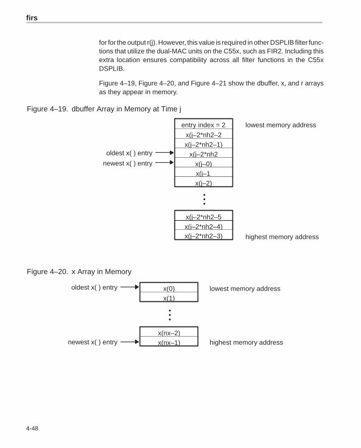
firs
4-48
for for the output r(j). However, this value is required in other DSPLIB filter func-tions that utilize the dual-MAC units on the C55x, such as FIR2. Including thisextra location ensures compatibility across all filter functions in the C55xDSPLIB.
Figure 4–19, Figure 4–20, and Figure 4–21 show the dbuffer, x, and r arraysas they appear in memory.
Figure 4–19. dbuffer Array in Memory at Time j
•••
x(j–2*nh2–5)
lowest memory address
highest memory address
oldest x( ) entry
entry index = 2
x(j–2*nh2–2)x(j–2*nh2–1)
x(j–2*nh2)x(j–0)
x(j–1)x(j–2)
x(j–2*nh2–4)x(j–2*nh2–3)
newest x( ) entry
Figure 4–20. x Array in Memory
•••
x(0)
x(nx–2)
lowest memory address
highest memory address
oldest x( ) entry
newest x( ) entry x(nx–1)
x(1)
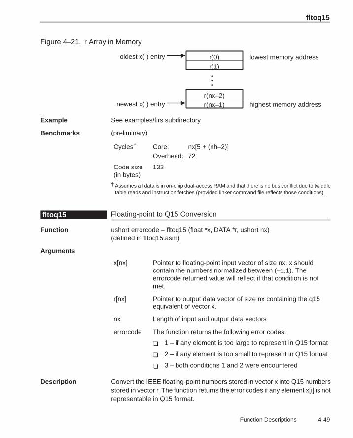
fltoq15
4-49 Function Descriptions
Figure 4–21. r Array in Memory
•••
r(nx–1)
lowest memory address
highest memory address
oldest x( ) entry
newest x( ) entry
r(0)
r(nx–2)
r(1)
Example See examples/firs subdirectory
Benchmarks (preliminary)
Cycles† Core: nx[5 + (nh–2)]Overhead: 72
Code size(in bytes)
133
† Assumes all data is in on-chip dual-access RAM and that there is no bus conflict due to twiddletable reads and instruction fetches (provided linker command file reflects those conditions).
Floating-point to Q15 Conversionfltoq15
Function ushort errorcode = fltoq15 (float *x, DATA *r, ushort nx)(defined in fltoq15.asm)
Arguments
x[nx] Pointer to floating-point input vector of size nx. x shouldcontain the numbers normalized between (–1,1). Theerrorcode returned value will reflect if that condition is notmet.
r[nx] Pointer to output data vector of size nx containing the q15equivalent of vector x.
nx Length of input and output data vectors
errorcode The function returns the following error codes:
� 1 – if any element is too large to represent in Q15 format
� 2 – if any element is too small to represent in Q15 format
� 3 – both conditions 1 and 2 were encountered
Description Convert the IEEE floating-point numbers stored in vector x into Q15 numbersstored in vector r. The function returns the error codes if any element x[i] is notrepresentable in Q15 format.
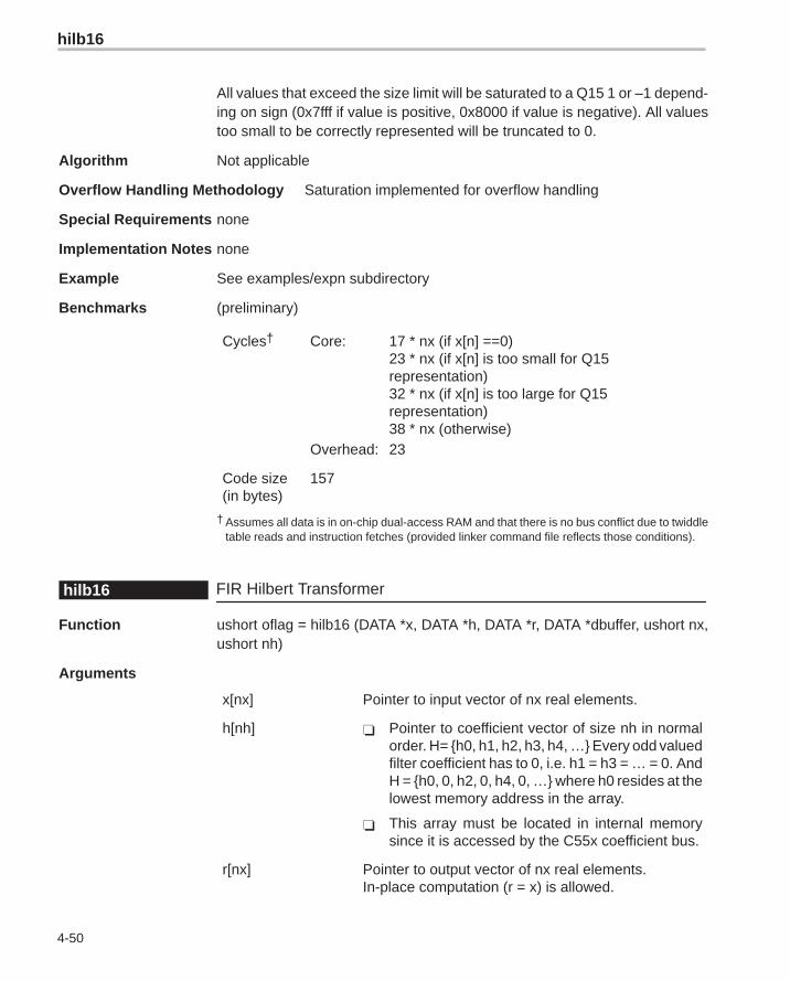
hilb16
4-50
All values that exceed the size limit will be saturated to a Q15 1 or –1 depend-ing on sign (0x7fff if value is positive, 0x8000 if value is negative). All valuestoo small to be correctly represented will be truncated to 0.
Algorithm Not applicable
Overflow Handling Methodology Saturation implemented for overflow handling
Special Requirements none
Implementation Notes none
Example See examples/expn subdirectory
Benchmarks (preliminary)
Cycles† Core: 17 * nx (if x[n] ==0)23 * nx (if x[n] is too small for Q15representation)32 * nx (if x[n] is too large for Q15representation)38 * nx (otherwise)
Overhead: 23
Code size(in bytes)
157
† Assumes all data is in on-chip dual-access RAM and that there is no bus conflict due to twiddletable reads and instruction fetches (provided linker command file reflects those conditions).
FIR Hilbert Transformerhilb16
Function ushort oflag = hilb16 (DATA *x, DATA *h, DATA *r, DATA *dbuffer, ushort nx,ushort nh)
Arguments
x[nx] Pointer to input vector of nx real elements.
h[nh] � Pointer to coefficient vector of size nh in normalorder. H= {h0, h1, h2, h3, h4, …} Every odd valuedfilter coefficient has to 0, i.e. h1 = h3 = … = 0. AndH = {h0, 0, h2, 0, h4, 0, …} where h0 resides at thelowest memory address in the array.
� This array must be located in internal memorysince it is accessed by the C55x coefficient bus.
r[nx] Pointer to output vector of nx real elements.In-place computation (r = x) is allowed.
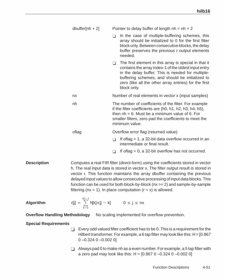
hilb16
4-51 Function Descriptions
dbuffer[nh + 2] Pointer to delay buffer of length nh = nh + 2
� In the case of multiple-buffering schemes, thisarray should be initialized to 0 for the first filterblock only. Between consecutive blocks, the delaybuffer preserves the previous r output elementsneeded.
� The first element in this array is special in that itcontains the array index-1 of the oldest input entryin the delay buffer. This is needed for multiple-buffering schemes, and should be initialized tozero (like all the other array entries) for the firstblock only.
nx Number of real elements in vector x (input samples)
nh The number of coefficients of the filter. For exampleif the filter coefficients are {h0, h1, h2, h3, h4, h5},then nh = 6. Must be a minimum value of 6. Forsmaller filters, zero pad the coefficients to meet theminimum value.
oflag Overflow error flag (returned value)
� If oflag = 1, a 32-bit data overflow occurred in anintermediate or final result.
� If oflag = 0, a 32-bit overflow has not occurred.
Description Computes a real FIR filter (direct-form) using the coefficients stored in vectorh. The real input data is stored in vector x. The filter output result is stored invector r. This function maintains the array dbuffer containing the previousdelayed input values to allow consecutive processing of input data blocks. Thisfunction can be used for both block-by-block (nx >= 2) and sample-by-samplefiltering (nx = 1). In place computation (r = x) is allowed.
Algorithm r[j] � �nh�1
k�0
h[k]x [j � k] 0 � j � nx
Overflow Handling Methodology No scaling implemented for overflow prevention.
Special Requirements� Every odd valued filter coefficient has to be 0. This is a requirement for the
Hilbert transformer. For example, a 6 tap filter may look like this: H = [0.8670 –0.324 0 –0.002 0]
� Always pad 0 to make nh as a even number. For example, a 5 tap filter witha zero pad may look like this: H = [0.867 0 –0.324 0 –0.002 0]
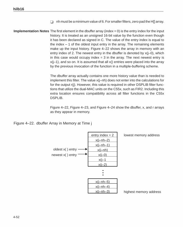
hilb16
4-52
� nh must be a minimum value of 6. For smaller filters, zero pad the H[] array.
Implementation Notes The first element in the dbuffer array (index = 0) is the entry index for the inputhistory. It is treated as an unsigned 16-bit value by the function even thoughit has been declared as signed in C. The value of the entry index is equal tothe index – 1 of the oldest input entry in the array. The remaining elementsmake up the input history. Figure 4–22 shows the array in memory with anentry index of 2. The newest entry in the dbuffer is denoted by x(j–0), whichin this case would occupy index = 3 in the array. The next newest entry isx(j–1), and so on. It is assumed that all x() entries were placed into the arrayby the previous invocation of the function in a multiple-buffering scheme.
The dbuffer array actually contains one more history value than is needed toimplement this filter. The value x(j–nh) does not enter into the calculations forfor the output r(j). However, this value is required in other DSPLIB filter func-tions that utilize the dual-MAC units on the C55x, such as FIR2. Including thisextra location ensures compatibility across all filter functions in the C55xDSPLIB.
Figure 4–22, Figure 4–23, and Figure 4–24 show the dbuffer, x, and r arraysas they appear in memory.
Figure 4–22. dbuffer Array in Memory at Time j
•••
x(j–nh–5)
lowest memory address
highest memory address
oldest x( ) entry
entry index = 2
x(j–nh–2)x(j–nh–1)
x(j–nh)x(j–0)x(j–1)x(j–2)
x(j–nh–4)x(j–nh–3)
newest x( ) entry
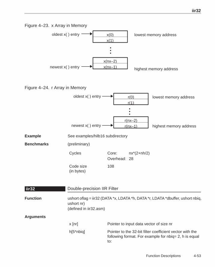
iir32
4-53 Function Descriptions
Figure 4–23. x Array in Memory
•••
x(0)
x(nx–2)
lowest memory address
highest memory address
oldest x( ) entry
newest x( ) entry x(nx–1)
x(1)
Figure 4–24. r Array in Memory
•••
r(nx–1)
lowest memory address
highest memory address
oldest x( ) entry
newest x( ) entry
r(0)
r(nx–2)
r(1)
Example See examples/hilb16 subdirectory
Benchmarks (preliminary)
Cycles Core: nx*(2+nh/2)Overhead: 28
Code size(in bytes)
108
Double-precision IIR Filteriir32
Function ushort oflag = iir32 (DATA *x, LDATA *h, DATA *r, LDATA *dbuffer, ushort nbiq,ushort nr)(defined in iir32.asm)
Arguments
x [nr] Pointer to input data vector of size nr
h[5*nbiq] Pointer to the 32-bit filter coefficient vector with thefollowing format. For example for nbiq= 2, h is equalto:
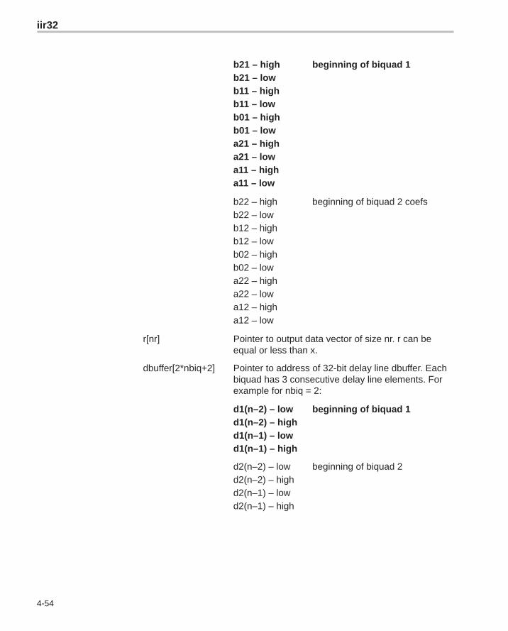
iir32
4-54
b21 – highb21 – lowb11 – highb11 – lowb01 – highb01 – lowa21 – higha21 – lowa11 – higha11 – low
beginning of biquad 1
b22 – highb22 – lowb12 – highb12 – lowb02 – highb02 – lowa22 – higha22 – lowa12 – higha12 – low
beginning of biquad 2 coefs
r[nr] Pointer to output data vector of size nr. r can beequal or less than x.
dbuffer[2*nbiq+2] Pointer to address of 32-bit delay line dbuffer. Eachbiquad has 3 consecutive delay line elements. Forexample for nbiq = 2:
d1(n–2) – lowd1(n–2) – highd1(n–1) – lowd1(n–1) – high
beginning of biquad 1
d2(n–2) – lowd2(n–2) – highd2(n–1) – lowd2(n–1) – high
beginning of biquad 2
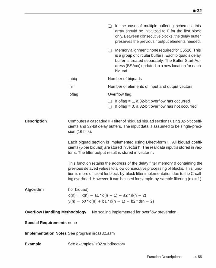
iir32
4-55 Function Descriptions
� In the case of multiple-buffering schemes, thisarray should be initialized to 0 for the first blockonly. Between consecutive blocks, the delay bufferpreserves the previous r output elements needed.
� Memory alignment: none required for C5510. Thisis a group of circular buffers. Each biquad’s delaybuffer is treated separately. The Buffer Start Ad-dress (BSAxx) updated to a new location for eachbiquad.
nbiq Number of biquads
nr Number of elements of input and output vectors
oflag Overflow flag.
� If oflag = 1, a 32-bit overflow has occurred� If oflag = 0, a 32-bit overflow has not occurred
Description Computes a cascaded IIR filter of nbiquad biquad sections using 32-bit coeffi-cients and 32-bit delay buffers. The input data is assumed to be single-preci-sion (16 bits).
Each biquad section is implemented using Direct-form II. All biquad coeffi-cients (5 per biquad) are stored in vector h. The real data input is stored in vec-tor x. The filter output result is stored in vector r .
This function retains the address of the delay filter memory d containing theprevious delayed values to allow consecutive processing of blocks. This func-tion is more efficient for block-by-block filter implementation due to the C-call-ing overhead. However, it can be used for sample-by-sample filtering (nx = 1).
Algorithm (for biquad)
d(n) � x(n) � a1 * d(n � 1) � a2 * d(n � 2)
y(n) � b0 * d(n) � b1 * d(n � 1) � b2 * d(n � 2)
Overflow Handling Methodology No scaling implemented for overflow prevention.
Special Requirements none
Implementation Notes See program iircas32.asm
Example See examples/iir32 subdirectory
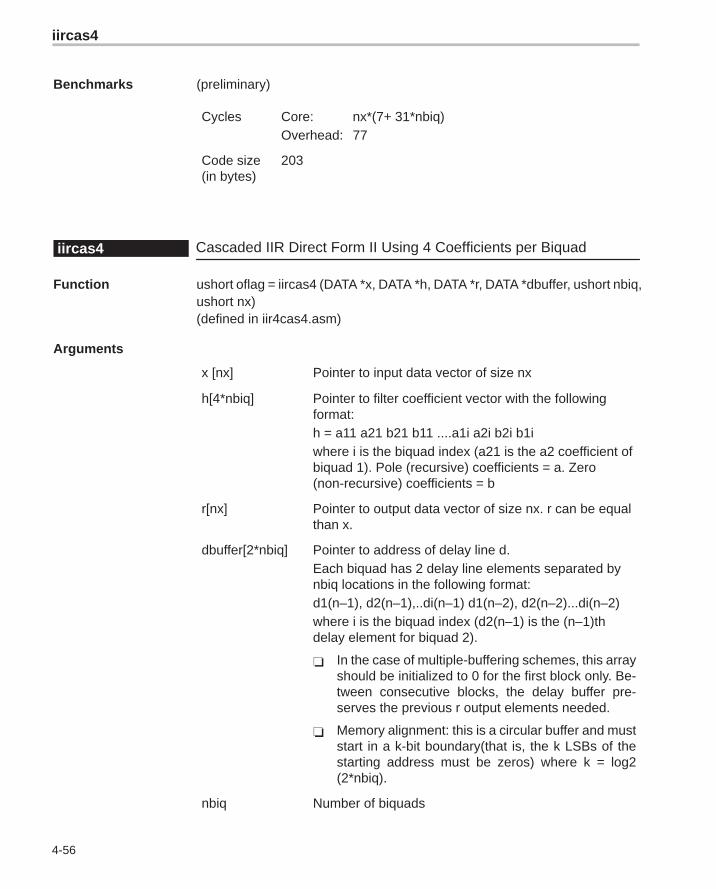
iircas4
4-56
Benchmarks (preliminary)
Cycles Core: nx*(7+ 31*nbiq)Overhead: 77
Code size(in bytes)
203
Cascaded IIR Direct Form II Using 4 Coefficients per Biquadiircas4
Function ushort oflag = iircas4 (DATA *x, DATA *h, DATA *r, DATA *dbuffer, ushort nbiq,ushort nx)(defined in iir4cas4.asm)
Arguments
x [nx] Pointer to input data vector of size nx
h[4*nbiq] Pointer to filter coefficient vector with the followingformat:h = a11 a21 b21 b11 ....a1i a2i b2i b1iwhere i is the biquad index (a21 is the a2 coefficient ofbiquad 1). Pole (recursive) coefficients = a. Zero(non-recursive) coefficients = b
r[nx] Pointer to output data vector of size nx. r can be equalthan x.
dbuffer[2*nbiq] Pointer to address of delay line d.Each biquad has 2 delay line elements separated bynbiq locations in the following format:d1(n–1), d2(n–1),..di(n–1) d1(n–2), d2(n–2)...di(n–2)where i is the biquad index (d2(n–1) is the (n–1)thdelay element for biquad 2).
� In the case of multiple-buffering schemes, this arrayshould be initialized to 0 for the first block only. Be-tween consecutive blocks, the delay buffer pre-serves the previous r output elements needed.
� Memory alignment: this is a circular buffer and muststart in a k-bit boundary(that is, the k LSBs of thestarting address must be zeros) where k = log2(2*nbiq).
nbiq Number of biquads
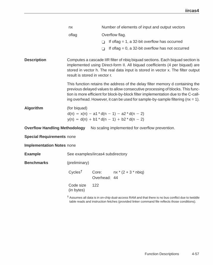
iircas4
4-57 Function Descriptions
nx Number of elements of input and output vectors
oflag Overflow flag.
� If oflag = 1, a 32-bit overflow has occurred
� If oflag = 0, a 32-bit overflow has not occurred
Description Computes a cascade IIR filter of nbiq biquad sections. Each biquad section isimplemented using Direct-form II. All biquad coefficients (4 per biquad) arestored in vector h. The real data input is stored in vector x. The filter outputresult is stored in vector r.
This function retains the address of the delay filter memory d containing theprevious delayed values to allow consecutive processing of blocks. This func-tion is more efficient for block-by-block filter implementation due to the C-call-ing overhead. However, it can be used for sample-by-sample filtering (nx = 1).
Algorithm (for biquad)d(n) � x(n) � a1 * d(n � 1) � a2 * d(n � 2)y(n) � d(n) � b1 * d(n � 1) � b2 * d(n � 2)
Overflow Handling Methodology No scaling implemented for overflow prevention.
Special Requirements none
Implementation Notes none
Example See examples/iircas4 subdirectory
Benchmarks (preliminary)
Cycles† Core: nx * (2 + 3 * nbiq)Overhead: 44
Code size(in bytes)
122
† Assumes all data is in on-chip dual-access RAM and that there is no bus conflict due to twiddletable reads and instruction fetches (provided linker command file reflects those conditions).
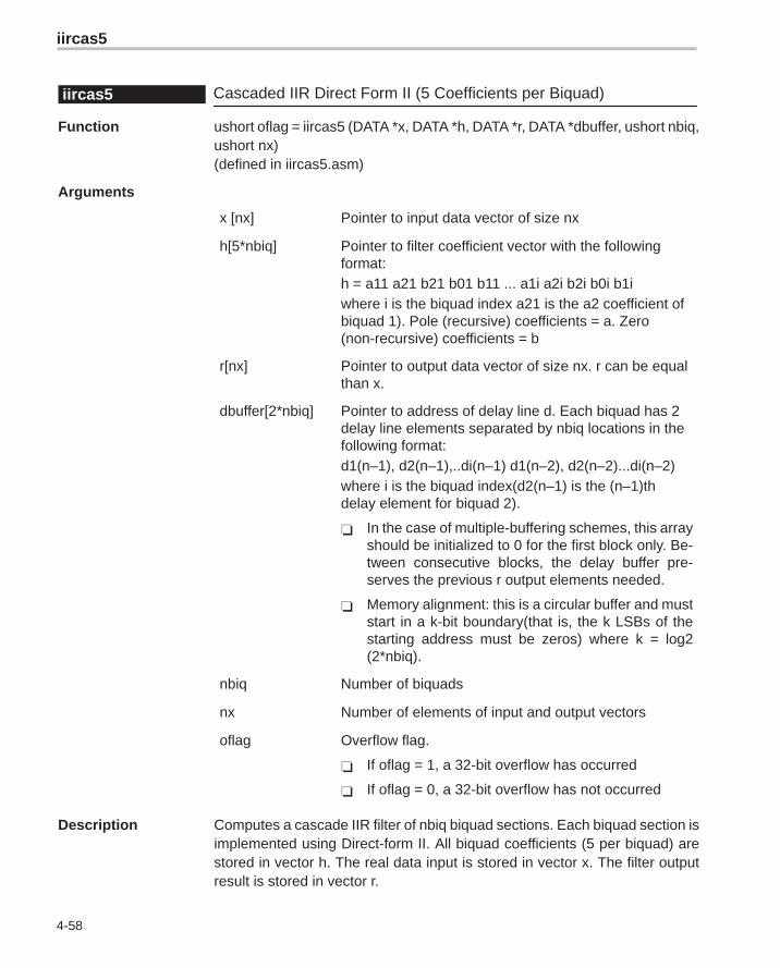
iircas5
4-58
Cascaded IIR Direct Form II (5 Coefficients per Biquad)iircas5
Function ushort oflag = iircas5 (DATA *x, DATA *h, DATA *r, DATA *dbuffer, ushort nbiq,ushort nx)(defined in iircas5.asm)
Arguments
x [nx] Pointer to input data vector of size nx
h[5*nbiq] Pointer to filter coefficient vector with the followingformat:h = a11 a21 b21 b01 b11 ... a1i a2i b2i b0i b1iwhere i is the biquad index a21 is the a2 coefficient ofbiquad 1). Pole (recursive) coefficients = a. Zero(non-recursive) coefficients = b
r[nx] Pointer to output data vector of size nx. r can be equalthan x.
dbuffer[2*nbiq] Pointer to address of delay line d. Each biquad has 2delay line elements separated by nbiq locations in thefollowing format:d1(n–1), d2(n–1),..di(n–1) d1(n–2), d2(n–2)...di(n–2)where i is the biquad index(d2(n–1) is the (n–1)thdelay element for biquad 2).
� In the case of multiple-buffering schemes, this arrayshould be initialized to 0 for the first block only. Be-tween consecutive blocks, the delay buffer pre-serves the previous r output elements needed.
� Memory alignment: this is a circular buffer and muststart in a k-bit boundary(that is, the k LSBs of thestarting address must be zeros) where k = log2(2*nbiq).
nbiq Number of biquads
nx Number of elements of input and output vectors
oflag Overflow flag.
� If oflag = 1, a 32-bit overflow has occurred
� If oflag = 0, a 32-bit overflow has not occurred
Description Computes a cascade IIR filter of nbiq biquad sections. Each biquad section isimplemented using Direct-form II. All biquad coefficients (5 per biquad) arestored in vector h. The real data input is stored in vector x. The filter outputresult is stored in vector r.
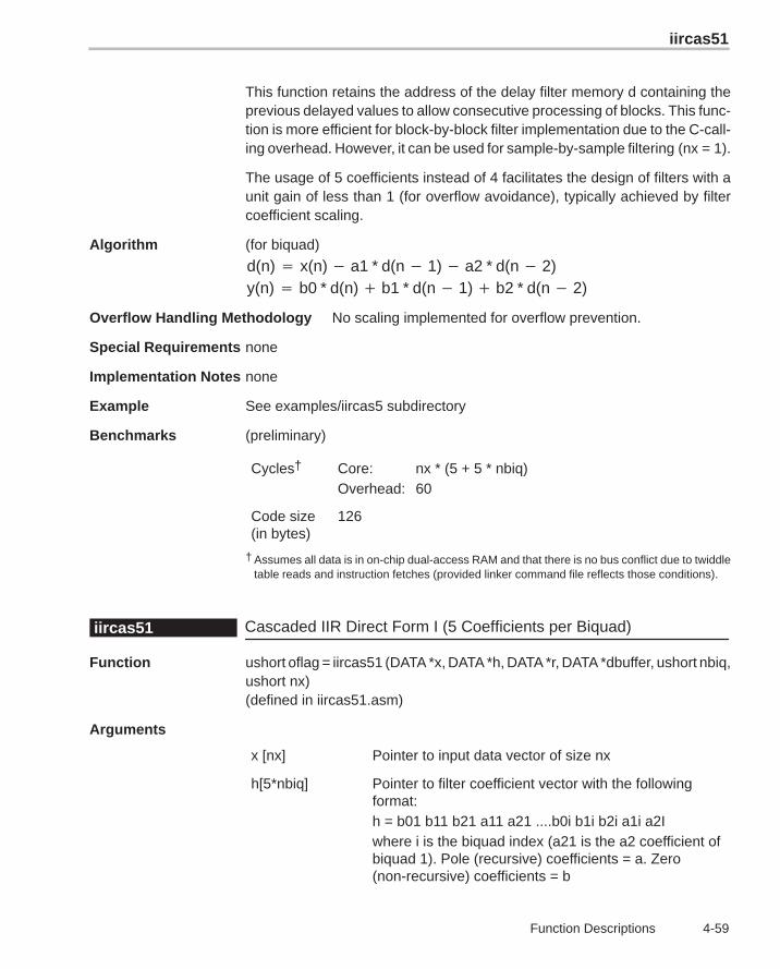
iircas51
4-59 Function Descriptions
This function retains the address of the delay filter memory d containing theprevious delayed values to allow consecutive processing of blocks. This func-tion is more efficient for block-by-block filter implementation due to the C-call-ing overhead. However, it can be used for sample-by-sample filtering (nx = 1).
The usage of 5 coefficients instead of 4 facilitates the design of filters with aunit gain of less than 1 (for overflow avoidance), typically achieved by filtercoefficient scaling.
Algorithm (for biquad)
d(n) � x(n) � a1 * d(n � 1) � a2 * d(n � 2)y(n) � b0 * d(n) � b1 * d(n � 1) � b2 * d(n � 2)
Overflow Handling Methodology No scaling implemented for overflow prevention.
Special Requirements none
Implementation Notes none
Example See examples/iircas5 subdirectory
Benchmarks (preliminary)
Cycles† Core: nx * (5 + 5 * nbiq)Overhead: 60
Code size(in bytes)
126
† Assumes all data is in on-chip dual-access RAM and that there is no bus conflict due to twiddletable reads and instruction fetches (provided linker command file reflects those conditions).
Cascaded IIR Direct Form I (5 Coefficients per Biquad)iircas51
Function ushort oflag = iircas51 (DATA *x, DATA *h, DATA *r, DATA *dbuffer, ushort nbiq,ushort nx)(defined in iircas51.asm)
Arguments
x [nx] Pointer to input data vector of size nx
h[5*nbiq] Pointer to filter coefficient vector with the followingformat:h = b01 b11 b21 a11 a21 ....b0i b1i b2i a1i a2Iwhere i is the biquad index (a21 is the a2 coefficient ofbiquad 1). Pole (recursive) coefficients = a. Zero(non-recursive) coefficients = b
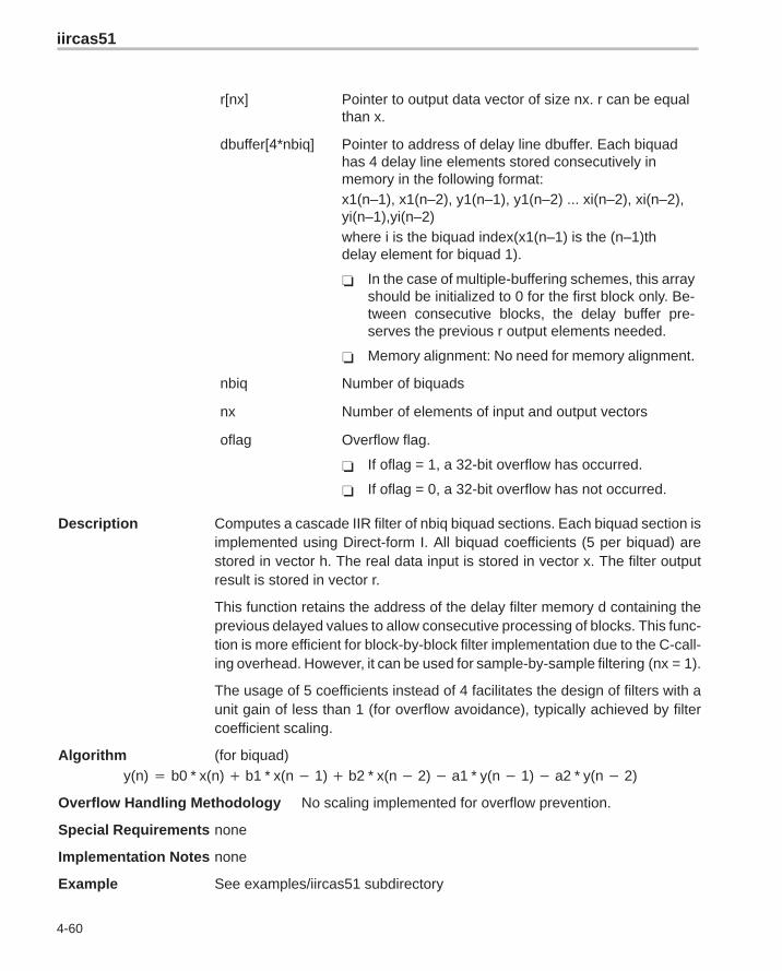
iircas51
4-60
r[nx] Pointer to output data vector of size nx. r can be equalthan x.
dbuffer[4*nbiq] Pointer to address of delay line dbuffer. Each biquadhas 4 delay line elements stored consecutively inmemory in the following format:x1(n–1), x1(n–2), y1(n–1), y1(n–2) ... xi(n–2), xi(n–2),yi(n–1),yi(n–2)where i is the biquad index(x1(n–1) is the (n–1)thdelay element for biquad 1).
� In the case of multiple-buffering schemes, this arrayshould be initialized to 0 for the first block only. Be-tween consecutive blocks, the delay buffer pre-serves the previous r output elements needed.
� Memory alignment: No need for memory alignment.
nbiq Number of biquads
nx Number of elements of input and output vectors
oflag Overflow flag.
� If oflag = 1, a 32-bit overflow has occurred.
� If oflag = 0, a 32-bit overflow has not occurred.
Description Computes a cascade IIR filter of nbiq biquad sections. Each biquad section isimplemented using Direct-form I. All biquad coefficients (5 per biquad) arestored in vector h. The real data input is stored in vector x. The filter outputresult is stored in vector r.
This function retains the address of the delay filter memory d containing theprevious delayed values to allow consecutive processing of blocks. This func-tion is more efficient for block-by-block filter implementation due to the C-call-ing overhead. However, it can be used for sample-by-sample filtering (nx = 1).
The usage of 5 coefficients instead of 4 facilitates the design of filters with aunit gain of less than 1 (for overflow avoidance), typically achieved by filtercoefficient scaling.
Algorithm (for biquad)y(n) � b0 * x(n) � b1 * x(n � 1) � b2 * x(n � 2) � a1 * y(n � 1) � a2 * y(n � 2)
Overflow Handling Methodology No scaling implemented for overflow prevention.
Special Requirements none
Implementation Notes none
Example See examples/iircas51 subdirectory
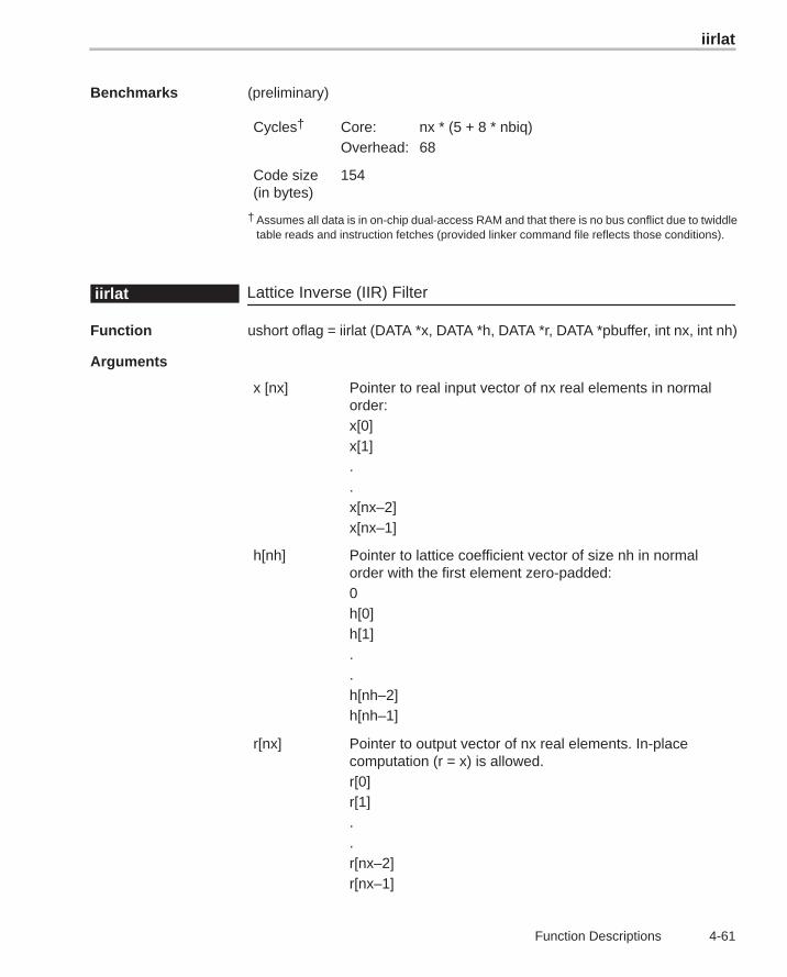
iirlat
4-61 Function Descriptions
Benchmarks (preliminary)
Cycles† Core: nx * (5 + 8 * nbiq)Overhead: 68
Code size(in bytes)
154
† Assumes all data is in on-chip dual-access RAM and that there is no bus conflict due to twiddletable reads and instruction fetches (provided linker command file reflects those conditions).
Lattice Inverse (IIR) Filteriirlat
Function ushort oflag = iirlat (DATA *x, DATA *h, DATA *r, DATA *pbuffer, int nx, int nh)
Arguments
x [nx] Pointer to real input vector of nx real elements in normalorder:x[0]x[1]..x[nx–2]x[nx–1]
h[nh] Pointer to lattice coefficient vector of size nh in normalorder with the first element zero-padded:0h[0]h[1]..h[nh–2]h[nh–1]
r[nx] Pointer to output vector of nx real elements. In-placecomputation (r = x) is allowed.r[0]r[1]..r[nx–2]r[nx–1]
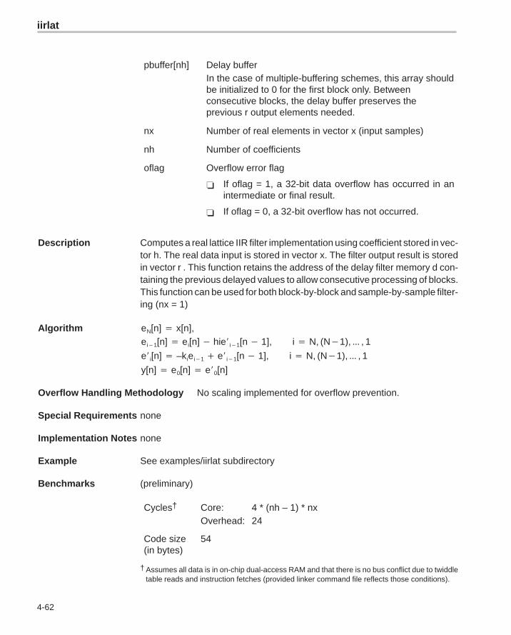
iirlat
4-62
pbuffer[nh] Delay bufferIn the case of multiple-buffering schemes, this array shouldbe initialized to 0 for the first block only. Betweenconsecutive blocks, the delay buffer preserves theprevious r output elements needed.
nx Number of real elements in vector x (input samples)
nh Number of coefficients
oflag Overflow error flag
� If oflag = 1, a 32-bit data overflow has occurred in anintermediate or final result.
� If oflag = 0, a 32-bit overflow has not occurred.
Description Computes a real lattice IIR filter implementation using coefficient stored in vec-tor h. The real data input is stored in vector x. The filter output result is storedin vector r . This function retains the address of the delay filter memory d con-taining the previous delayed values to allow consecutive processing of blocks.This function can be used for both block-by-block and sample-by-sample filter-ing (nx = 1)
Algorithm eN[n] � x[n],ei�1[n] � ei[n] � hie�i�1[n � 1], i � N, (N�1), ��� , 1
e�i[n] � –kiei�1 � e�i�1[n � 1], i � N, (N�1), ��� , 1
y[n] � e0[n] � e�0[n]
Overflow Handling Methodology No scaling implemented for overflow prevention.
Special Requirements none
Implementation Notes none
Example See examples/iirlat subdirectory
Benchmarks (preliminary)
Cycles† Core: 4 * (nh – 1) * nxOverhead: 24
Code size(in bytes)
54
† Assumes all data is in on-chip dual-access RAM and that there is no bus conflict due to twiddletable reads and instruction fetches (provided linker command file reflects those conditions).
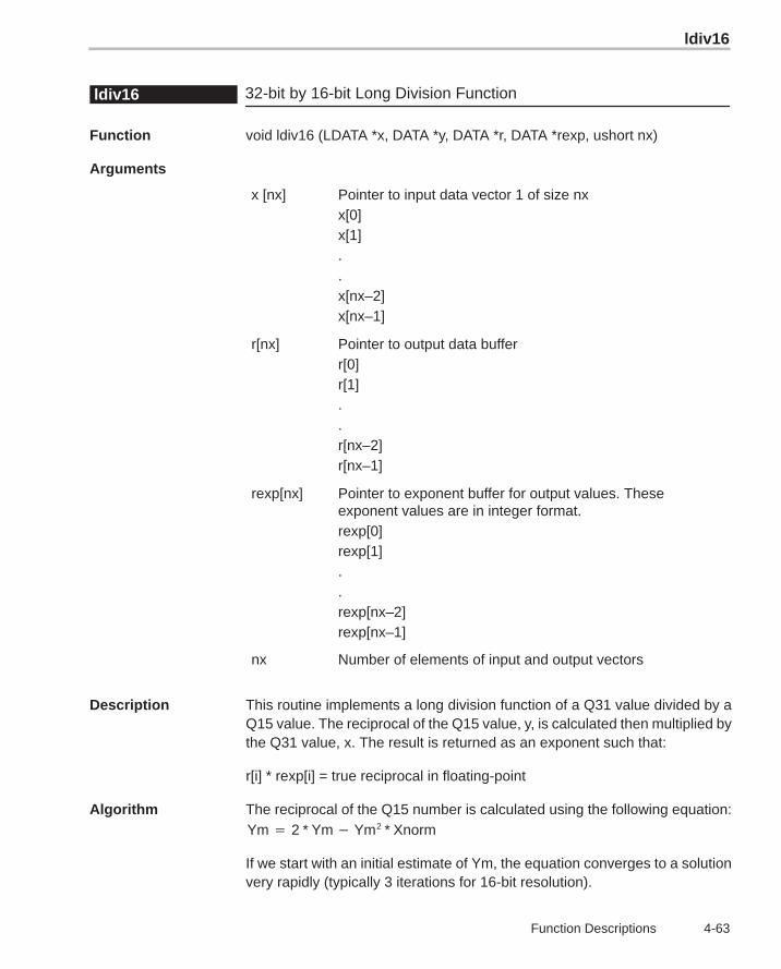
ldiv16
4-63 Function Descriptions
32-bit by 16-bit Long Division Functionldiv16
Function void ldiv16 (LDATA *x, DATA *y, DATA *r, DATA *rexp, ushort nx)
Arguments
x [nx] Pointer to input data vector 1 of size nxx[0]x[1]..x[nx–2]x[nx–1]
r[nx] Pointer to output data bufferr[0]r[1]..r[nx–2]r[nx–1]
rexp[nx] Pointer to exponent buffer for output values. Theseexponent values are in integer format.rexp[0]rexp[1]..rexp[nx–2]rexp[nx–1]
nx Number of elements of input and output vectors
Description This routine implements a long division function of a Q31 value divided by aQ15 value. The reciprocal of the Q15 value, y, is calculated then multiplied bythe Q31 value, x. The result is returned as an exponent such that:
r[i] * rexp[i] = true reciprocal in floating-point
Algorithm The reciprocal of the Q15 number is calculated using the following equation:Ym � 2 * Ym � Ym2 * Xnorm
If we start with an initial estimate of Ym, the equation converges to a solutionvery rapidly (typically 3 iterations for 16-bit resolution).
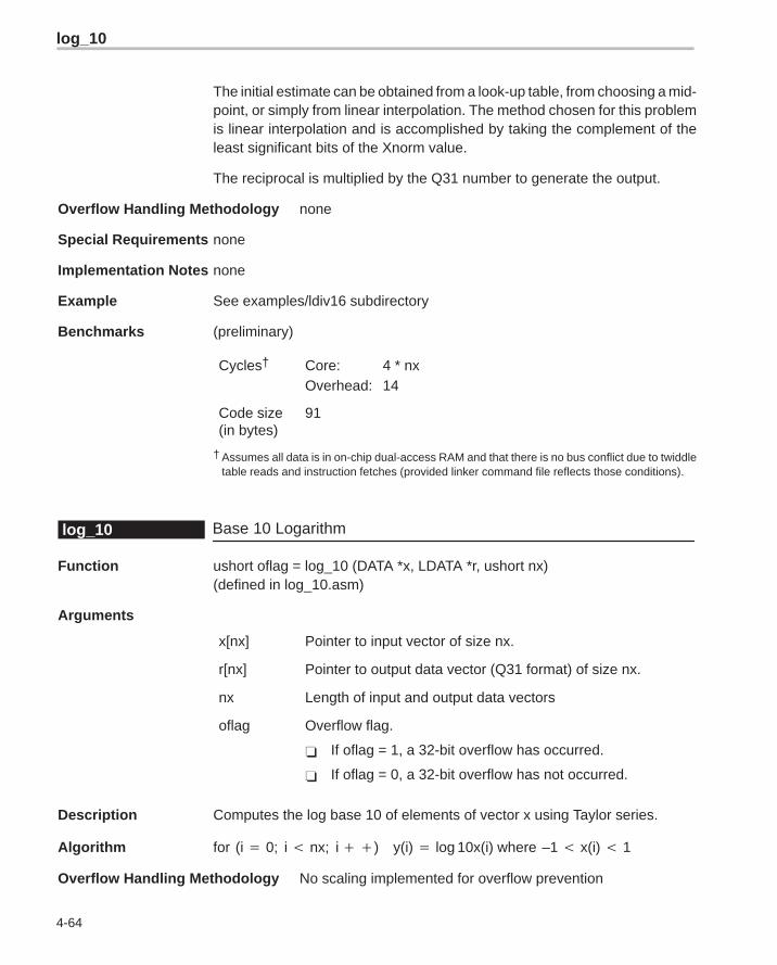
log_10
4-64
The initial estimate can be obtained from a look-up table, from choosing a mid-point, or simply from linear interpolation. The method chosen for this problemis linear interpolation and is accomplished by taking the complement of theleast significant bits of the Xnorm value.
The reciprocal is multiplied by the Q31 number to generate the output.
Overflow Handling Methodology none
Special Requirements none
Implementation Notes none
Example See examples/ldiv16 subdirectory
Benchmarks (preliminary)
Cycles† Core: 4 * nxOverhead: 14
Code size(in bytes)
91
† Assumes all data is in on-chip dual-access RAM and that there is no bus conflict due to twiddletable reads and instruction fetches (provided linker command file reflects those conditions).
Base 10 Logarithmlog_10
Function ushort oflag = log_10 (DATA *x, LDATA *r, ushort nx)(defined in log_10.asm)
Arguments
x[nx] Pointer to input vector of size nx.
r[nx] Pointer to output data vector (Q31 format) of size nx.
nx Length of input and output data vectors
oflag Overflow flag.
� If oflag = 1, a 32-bit overflow has occurred.
� If oflag = 0, a 32-bit overflow has not occurred.
Description Computes the log base 10 of elements of vector x using Taylor series.
Algorithm for (i � 0; i � nx; i ��) y(i) � log 10x(i) where –1 � x(i) � 1
Overflow Handling Methodology No scaling implemented for overflow prevention
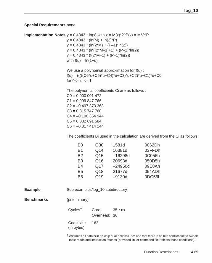
log_10
4-65 Function Descriptions
Special Requirements none
Implementation Notes y = 0.4343 * ln(x) with x = M(x)*2^P(x) = M*2^Py = 0.4343 * (ln(M) + ln(2)*P)y = 0.4343 * (ln(2*M) + (P–1)*ln(2))y = 0.4343 * (ln((2*M–1)+1) + (P–1)*ln(2))y = 0.4343 * (f(2*M–1) + (P–1)*ln(2))with f(u) = ln(1+u).
We use a polynomial approximation for f(u) :f(u) = (((((C6*u+C5)*u+C4)*u+C3)*u+C2)*u+C1)*u+C0for 0<= u <= 1.
The polynomial coefficients Ci are as follows :C0 = 0.000 001 472C1 = 0.999 847 766C2 = –0.497 373 368C3 = 0.315 747 760C4 = –0.190 354 944C5 = 0.082 691 584C6 = –0.017 414 144
The coefficients Bi used in the calculation are derived from the Ci as follows:
B0 Q30 1581d 0062DhB1 Q14 16381d 03FFDhB2 Q15 –16298d 0C056hB3 Q16 20693d 050D5hB4 Q17 –24950d 09E8AhB5 Q18 21677d 054ADhB6 Q19 –9130d 0DC56h
Example See examples/log_10 subdirectory
Benchmarks (preliminary)
Cycles† Core: 35 * nxOverhead: 36
Code size(in bytes)
162
† Assumes all data is in on-chip dual-access RAM and that there is no bus conflict due to twiddletable reads and instruction fetches (provided linker command file reflects those conditions).
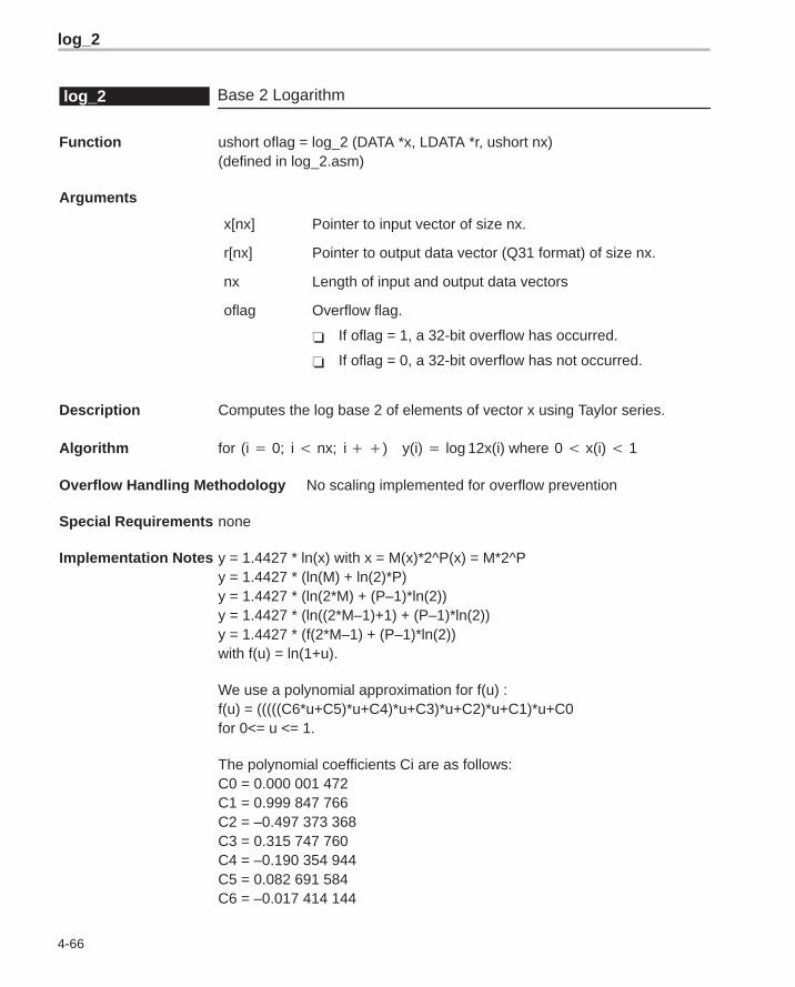
log_2
4-66
Base 2 Logarithmlog_2
Function ushort oflag = log_2 (DATA *x, LDATA *r, ushort nx)(defined in log_2.asm)
Arguments
x[nx] Pointer to input vector of size nx.
r[nx] Pointer to output data vector (Q31 format) of size nx.
nx Length of input and output data vectors
oflag Overflow flag.
� If oflag = 1, a 32-bit overflow has occurred.
� If oflag = 0, a 32-bit overflow has not occurred.
Description Computes the log base 2 of elements of vector x using Taylor series.
Algorithm for (i � 0; i � nx; i ��) y(i) � log 12x(i) where 0 � x(i) � 1
Overflow Handling Methodology No scaling implemented for overflow prevention
Special Requirements none
Implementation Notes y = 1.4427 * ln(x) with x = M(x)*2^P(x) = M*2^Py = 1.4427 * (ln(M) + ln(2)*P)y = 1.4427 * (ln(2*M) + (P–1)*ln(2))y = 1.4427 * (ln((2*M–1)+1) + (P–1)*ln(2))y = 1.4427 * (f(2*M–1) + (P–1)*ln(2))with f(u) = ln(1+u).
We use a polynomial approximation for f(u) :f(u) = (((((C6*u+C5)*u+C4)*u+C3)*u+C2)*u+C1)*u+C0for 0<= u <= 1.
The polynomial coefficients Ci are as follows:C0 = 0.000 001 472C1 = 0.999 847 766C2 = –0.497 373 368C3 = 0.315 747 760C4 = –0.190 354 944C5 = 0.082 691 584C6 = –0.017 414 144
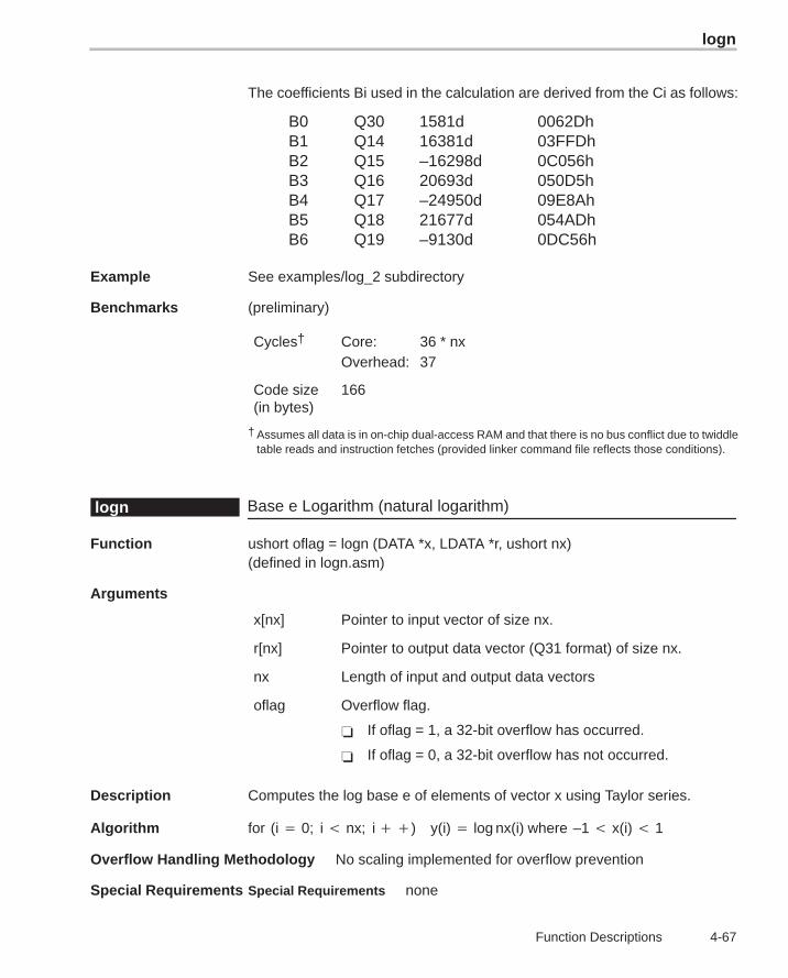
logn
4-67 Function Descriptions
The coefficients Bi used in the calculation are derived from the Ci as follows:
B0 Q30 1581d 0062DhB1 Q14 16381d 03FFDhB2 Q15 –16298d 0C056hB3 Q16 20693d 050D5hB4 Q17 –24950d 09E8AhB5 Q18 21677d 054ADhB6 Q19 –9130d 0DC56h
Example See examples/log_2 subdirectory
Benchmarks (preliminary)
Cycles† Core: 36 * nxOverhead: 37
Code size(in bytes)
166
† Assumes all data is in on-chip dual-access RAM and that there is no bus conflict due to twiddletable reads and instruction fetches (provided linker command file reflects those conditions).
Base e Logarithm (natural logarithm)logn
Function ushort oflag = logn (DATA *x, LDATA *r, ushort nx)(defined in logn.asm)
Arguments
x[nx] Pointer to input vector of size nx.
r[nx] Pointer to output data vector (Q31 format) of size nx.
nx Length of input and output data vectors
oflag Overflow flag.
� If oflag = 1, a 32-bit overflow has occurred.
� If oflag = 0, a 32-bit overflow has not occurred.
Description Computes the log base e of elements of vector x using Taylor series.
Algorithm for (i � 0; i � nx; i ��) y(i) � log nx(i) where –1 � x(i) � 1
Overflow Handling Methodology No scaling implemented for overflow prevention
Special Requirements Special Requirements none
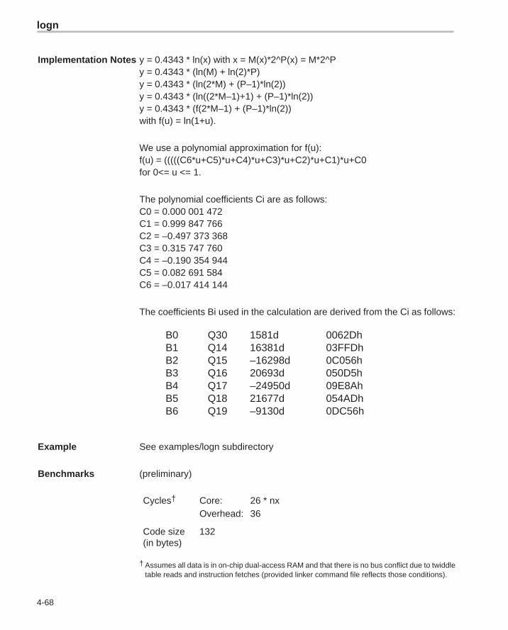
logn
4-68
Implementation Notes y = 0.4343 * ln(x) with x = M(x)*2^P(x) = M*2^Py = 0.4343 * (ln(M) + ln(2)*P)y = 0.4343 * (ln(2*M) + (P–1)*ln(2))y = 0.4343 * (ln((2*M–1)+1) + (P–1)*ln(2))y = 0.4343 * (f(2*M–1) + (P–1)*ln(2))with f(u) = ln(1+u).
We use a polynomial approximation for f(u):f(u) = (((((C6*u+C5)*u+C4)*u+C3)*u+C2)*u+C1)*u+C0for 0<= u <= 1.
The polynomial coefficients Ci are as follows:C0 = 0.000 001 472C1 = 0.999 847 766C2 = –0.497 373 368C3 = 0.315 747 760C4 = –0.190 354 944C5 = 0.082 691 584C6 = –0.017 414 144
The coefficients Bi used in the calculation are derived from the Ci as follows:
B0 Q30 1581d 0062DhB1 Q14 16381d 03FFDhB2 Q15 –16298d 0C056hB3 Q16 20693d 050D5hB4 Q17 –24950d 09E8AhB5 Q18 21677d 054ADhB6 Q19 –9130d 0DC56h
Example See examples/logn subdirectory
Benchmarks (preliminary)
Cycles† Core: 26 * nxOverhead: 36
Code size(in bytes)
132
† Assumes all data is in on-chip dual-access RAM and that there is no bus conflict due to twiddletable reads and instruction fetches (provided linker command file reflects those conditions).
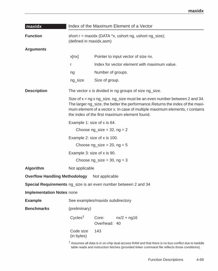
maxidx
4-69 Function Descriptions
Index of the Maximum Element of a Vectormaxidx
Function short r = maxidx (DATA *x, ushort ng, ushort ng_size);(defined in maxidx.asm)
Arguments
x[nx] Pointer to input vector of size nx.
r Index for vector element with maximum value.
ng Number of groups.
ng_size Size of group.
Description The vector x is divided in ng groups of size ng_size.
Size of x = ng x ng_size. ng_size must be an even number between 2 and 34.The larger ng_size, the better the performance.Returns the index of the maxi-mum element of a vector x. In case of multiple maximum elements, r containsthe index of the first maximum element found.
Example 1: size of x is 64.
Choose ng_size = 32, ng = 2
Example 2: size of x is 100.
Choose ng_size = 20, ng = 5
Example 3: size of x is 90.
Choose ng_size = 30, ng = 3
Algorithm Not applicable
Overflow Handling Methodology Not applicable
Special Requirements ng_size is an even number between 2 and 34
Implementation Notes none
Example See examples/maxidx subdirectory
Benchmarks (preliminary)
Cycles† Core: nx/2 + ng16Overhead: 40
Code size(in bytes)
143
† Assumes all data is in on-chip dual-access RAM and that there is no bus conflict due to twiddletable reads and instruction fetches (provided linker command file reflects those conditions).
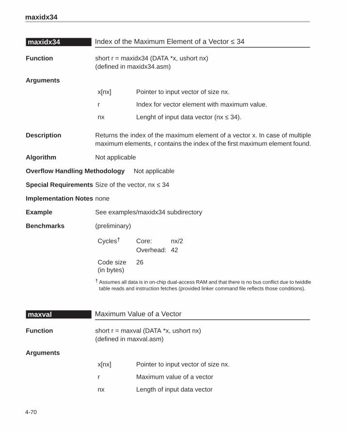
maxidx34
4-70
Index of the Maximum Element of a Vector ≤ 34maxidx34
Function short r = maxidx34 (DATA *x, ushort nx)(defined in maxidx34.asm)
Arguments
x[nx] Pointer to input vector of size nx.
r Index for vector element with maximum value.
nx Lenght of input data vector (nx ≤ 34).
Description Returns the index of the maximum element of a vector x. In case of multiplemaximum elements, r contains the index of the first maximum element found.
Algorithm Not applicable
Overflow Handling Methodology Not applicable
Special Requirements Size of the vector, nx ≤ 34
Implementation Notes none
Example See examples/maxidx34 subdirectory
Benchmarks (preliminary)
Cycles† Core: nx/2Overhead: 42
Code size(in bytes)
26
† Assumes all data is in on-chip dual-access RAM and that there is no bus conflict due to twiddletable reads and instruction fetches (provided linker command file reflects those conditions).
Maximum Value of a Vectormaxval
Function short r = maxval (DATA *x, ushort nx)(defined in maxval.asm)
Arguments
x[nx] Pointer to input vector of size nx.
r Maximum value of a vector
nx Length of input data vector
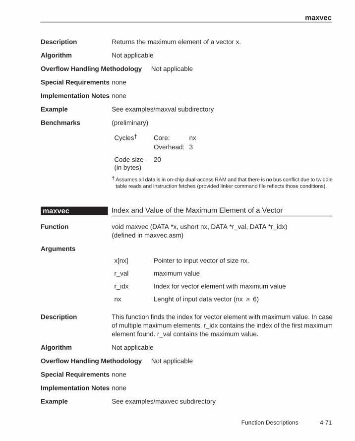
maxvec
4-71 Function Descriptions
Description Returns the maximum element of a vector x.
Algorithm Not applicable
Overflow Handling Methodology Not applicable
Special Requirements none
Implementation Notes none
Example See examples/maxval subdirectory
Benchmarks (preliminary)
Cycles† Core: nxOverhead: 3
Code size(in bytes)
20
† Assumes all data is in on-chip dual-access RAM and that there is no bus conflict due to twiddletable reads and instruction fetches (provided linker command file reflects those conditions).
Index and Value of the Maximum Element of a Vectormaxvec
Function void maxvec (DATA *x, ushort nx, DATA *r_val, DATA *r_idx)(defined in maxvec.asm)
Arguments
x[nx] Pointer to input vector of size nx.
r_val maximum value
r_idx Index for vector element with maximum value
nx Lenght of input data vector (nx 6)
Description This function finds the index for vector element with maximum value. In caseof multiple maximum elements, r_idx contains the index of the first maximumelement found. r_val contains the maximum value.
Algorithm Not applicable
Overflow Handling Methodology Not applicable
Special Requirements none
Implementation Notes none
Example See examples/maxvec subdirectory
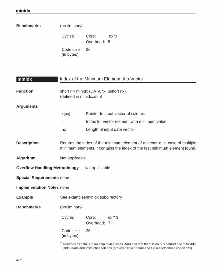
minidx
4-72
Benchmarks (preliminary)
Cycles Core: nx*3Overhead: 8
Code size(in bytes)
26
Index of the Minimum Element of a Vectorminidx
Function short r = minidx (DATA *x, ushort nx)(defined in minidx.asm)
Arguments
x[nx] Pointer to input vector of size nx.
r Index for vector element with minimum value
nx Length of input data vector
Description Returns the index of the minimum element of a vector x. In case of multipleminimum elements, r contains the index of the first minimum element found.
Algorithm Not applicable
Overflow Handling Methodology Not applicable
Special Requirements none
Implementation Notes none
Example See examples/minidx subdirectory
Benchmarks (preliminary)
Cycles† Core: nx * 3Overhead: 7
Code size(in bytes)
26
† Assumes all data is in on-chip dual-access RAM and that there is no bus conflict due to twiddletable reads and instruction fetches (provided linker command file reflects those conditions).
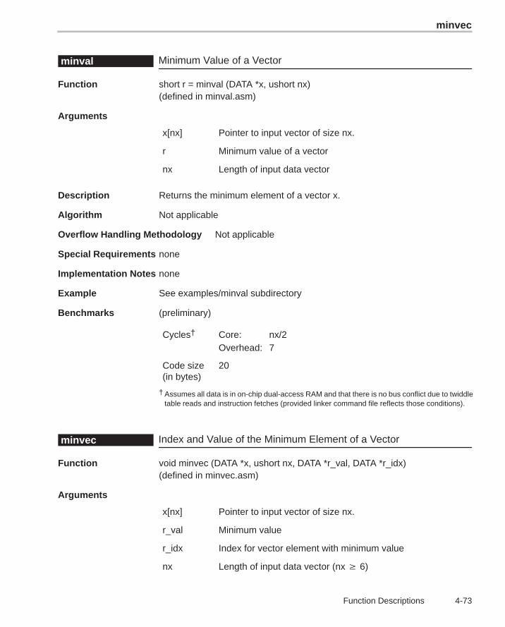
minvec
4-73 Function Descriptions
Minimum Value of a Vectorminval
Function short r = minval (DATA *x, ushort nx)(defined in minval.asm)
Arguments
x[nx] Pointer to input vector of size nx.
r Minimum value of a vector
nx Length of input data vector
Description Returns the minimum element of a vector x.
Algorithm Not applicable
Overflow Handling Methodology Not applicable
Special Requirements none
Implementation Notes none
Example See examples/minval subdirectory
Benchmarks (preliminary)
Cycles† Core: nx/2Overhead: 7
Code size(in bytes)
20
† Assumes all data is in on-chip dual-access RAM and that there is no bus conflict due to twiddletable reads and instruction fetches (provided linker command file reflects those conditions).
Index and Value of the Minimum Element of a Vectorminvec
Function void minvec (DATA *x, ushort nx, DATA *r_val, DATA *r_idx)(defined in minvec.asm)
Arguments
x[nx] Pointer to input vector of size nx.
r_val Minimum value
r_idx Index for vector element with minimum value
nx Length of input data vector (nx 6)
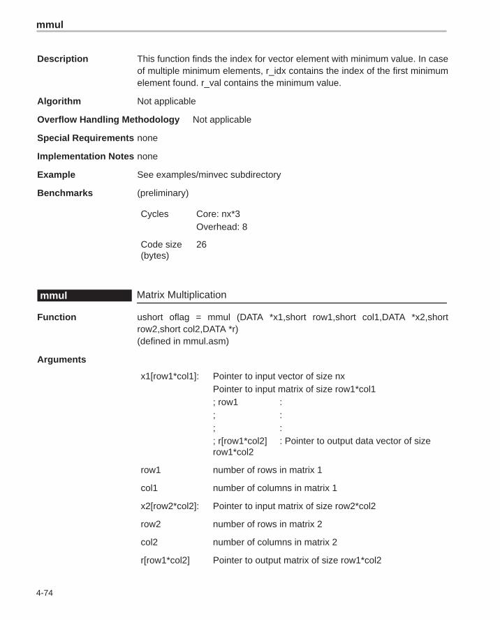
mmul
4-74
Description This function finds the index for vector element with minimum value. In caseof multiple minimum elements, r_idx contains the index of the first minimumelement found. r_val contains the minimum value.
Algorithm Not applicable
Overflow Handling Methodology Not applicable
Special Requirements none
Implementation Notes none
Example See examples/minvec subdirectory
Benchmarks (preliminary)
Cycles Core: nx*3Overhead: 8
Code size(bytes)
26
Matrix Multiplicationmmul
Function ushort oflag = mmul (DATA *x1,short row1,short col1,DATA *x2,shortrow2,short col2,DATA *r)(defined in mmul.asm)
Arguments
x1[row1*col1]: Pointer to input vector of size nxPointer to input matrix of size row1*col1; row1 :; :; :; r[row1*col2] : Pointer to output data vector of sizerow1*col2
row1 number of rows in matrix 1
col1 number of columns in matrix 1
x2[row2*col2]: Pointer to input matrix of size row2*col2
row2 number of rows in matrix 2
col2 number of columns in matrix 2
r[row1*col2] Pointer to output matrix of size row1*col2
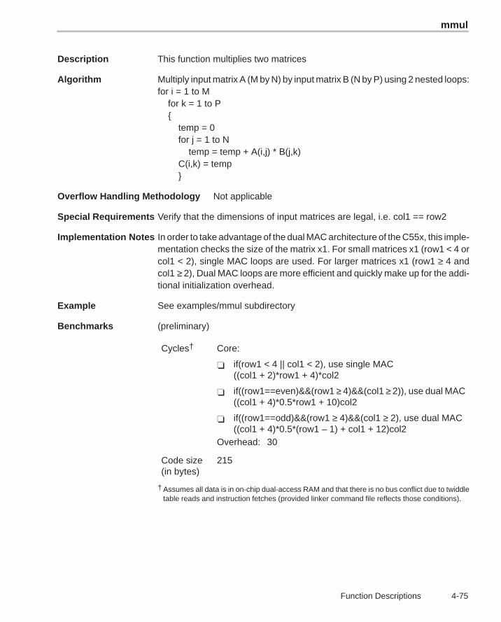
mmul
4-75 Function Descriptions
Description This function multiplies two matrices
Algorithm Multiply input matrix A (M by N) by input matrix B (N by P) using 2 nested loops:for i = 1 to M for k = 1 to P { temp = 0 for j = 1 to N temp = temp + A(i,j) * B(j,k) C(i,k) = temp }
Overflow Handling Methodology Not applicable
Special Requirements Verify that the dimensions of input matrices are legal, i.e. col1 == row2
Implementation Notes In order to take advantage of the dual MAC architecture of the C55x, this imple-mentation checks the size of the matrix x1. For small matrices x1 (row1 < 4 orcol1 < 2), single MAC loops are used. For larger matrices x1 (row1 ≥ 4 andcol1 ≥ 2), Dual MAC loops are more efficient and quickly make up for the addi-tional initialization overhead.
Example See examples/mmul subdirectory
Benchmarks (preliminary)
Cycles† Core:
� if(row1 < 4 || col1 < 2), use single MAC((col1 + 2)*row1 + 4)*col2
� if((row1==even)&&(row1 ≥ 4)&&(col1 ≥ 2)), use dual MAC((col1 + 4)*0.5*row1 + 10)col2
� if((row1==odd)&&(row1 ≥ 4)&&(col1 ≥ 2), use dual MAC((col1 + 4)*0.5*(row1 – 1) + col1 + 12)col2
Overhead: 30
Code size(in bytes)
215
† Assumes all data is in on-chip dual-access RAM and that there is no bus conflict due to twiddletable reads and instruction fetches (provided linker command file reflects those conditions).
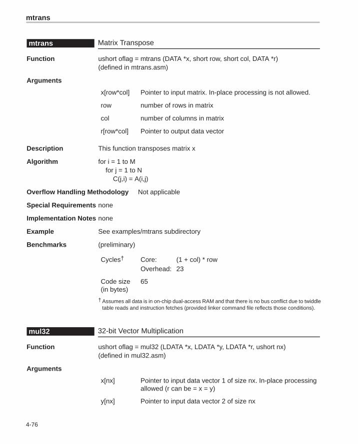
mtrans
4-76
Matrix Transposemtrans
Function ushort oflag = mtrans (DATA *x, short row, short col, DATA *r)(defined in mtrans.asm)
Arguments
x[row*col] Pointer to input matrix. In-place processing is not allowed.
row number of rows in matrix
col number of columns in matrix
r[row*col] Pointer to output data vector
Description This function transposes matrix x
Algorithm for i = 1 to M for j = 1 to N C(j,i) = A(i,j)
Overflow Handling Methodology Not applicable
Special Requirements none
Implementation Notes none
Example See examples/mtrans subdirectory
Benchmarks (preliminary)
Cycles† Core: (1 + col) * rowOverhead: 23
Code size(in bytes)
65
† Assumes all data is in on-chip dual-access RAM and that there is no bus conflict due to twiddletable reads and instruction fetches (provided linker command file reflects those conditions).
32-bit Vector Multiplicationmul32
Function ushort oflag = mul32 (LDATA *x, LDATA *y, LDATA *r, ushort nx)(defined in mul32.asm)
Arguments
x[nx] Pointer to input data vector 1 of size nx. In-place processingallowed (r can be = x = y)
y[nx] Pointer to input data vector 2 of size nx
neg
4-77 Function Descriptions
r[nx] Pointer to output data vector of size nx containing
nx Number of elements of input and output vectors. Nx 4
oflag Overflow flag
� If oflag = 1, a 32-bit overflow has occurred� If oflag = 0, a 32-bit overflow has not occurred
Description This function multiplies two 32-bit Q31 vectors, element by element, andproduces a 32-bit Q31 vector.
Algorithm for (i=0; i < nx; i++)z (i) = x (i) * y (i)
Overflow Handling Methodology Scaling implemented for overflow prevention (user selectable)
Special Requirements none
Implementation Notes none
Example See examples/add subdirectory
Benchmarks
Cycles Core: 4*nx + 4Overhead 21
Code size(in bytes)
73
Vector Negateneg
Function ushort oflag = neg (DATA *x, DATA *r, ushort nx)(defined in neg.asm)
Arguments
x[nx] Pointer to input data vector 1 of size nx. In-place processingallowed (r can be = x = y)
r[nx] Pointer to output data vector of size nx. In-place processingallowedSpecial cases:
� if x[I] = –1 = 32768 , then r = 1 = 321767 with oflag = 1
� if x= 1 = 32767 , then r = –1 = 321768 with oflag = 1
neg32
4-78
nx Number of elements of input and output vectors.nx ≥ 4
oflag Overflow flag.
� If oflag = 1, a 32-bit overflow has occurred.
� If oflag = 0, a 32-bit overflow has not occurred.Caution: overflow in negation of a Q15 number can happennaturally when negating (–1).
Description This function negates each of the elements of a vector (fractional values).
Algorithm for (i � 0; i � nx; i ��) x(i) � –x(i)
Overflow Handling Methodology Saturation implemented for overflow handling
Special Requirements none
Implementation Notes none
Example See examples/neg subdirectory
Benchmarks (preliminary)
Cycles† Core: 4 * nxOverhead: 13
Code size(in bytes)
61
† Assumes all data is in on-chip dual-access RAM and that there is no bus conflict due to twiddletable reads and instruction fetches (provided linker command file reflects those conditions).
Vector Negate (double precision)neg32
Function ushort oflag = neg32 (LDATA *x, LDATA *r, ushort nx)(defined in neg.asm)
Arguments
x[nx] Pointer to input data vector 1 of size nx. In-place processingallowed (r can be = x = y)
r[nx] Pointer to output data vector of size nx. In-place processingallowedSpecial cases:
� if x = –1 = 32768 * 216, then r = 1 = 321767 * 216 with oflag= 1
� if x= 1 = 32767 * 216, then r = –1 = 321768 * 216 with oflag= 1
power
4-79 Function Descriptions
nx Number of elements of input and output vectors.nx ≥ 4
oflag Overflow flag.
� If oflag = 1, a 32-bit overflow has occurred.
� If oflag = 0, a 32-bit overflow has not occurred.Caution: overflow in negation of a Q31 number can happennaturally when negating (–1).
Description This function negates each of the elements of a vector (fractional values).
Algorithm for (i � 0; i � nx; i ��) x(i) � –x(i)
Overflow Handling Methodology Saturation implemented for overflow handling
Special Requirements none
Implementation Notes none
Example See examples/neg32 subdirectory
Benchmarks (preliminary)
Cycles† Core: 4 * nxOverhead: 13
Code size(in bytes)
61
† Assumes all data is in on-chip dual-access RAM and that there is no bus conflict due to twiddletable reads and instruction fetches (provided linker command file reflects those conditions).
Vector Powerpower
Function ushort oflag = power (DATA *x, LDATA *r, ushort nx)(defined in power.asm)
Arguments
x[nx] Pointer to input data vector 1 of size nx. In-place processingallowed (r can be = x = y)
r[1] Pointer to output data vector element in Q31 formatSpecial cases:
� if x= –1 = 32768*216 , then r = 1 = 321767*216 with oflag = 1
� if x= 1 = 32767*216 , then r = –1 = 321768*216 with oflag = 1
q15tofl
4-80
nx Number of elements of input vectors.nx ≥ 4
oflag Overflow flag.
� If oflag = 1, a 32-bit overflow has occurred.
� If oflag = 0, a 32-bit overflow has not occurred.
Description This function calculates the power (sum of products) of a vector.
Algorithm Power = 0 for (i � 0; i � nx; i ��) power �� x(i) * x(I)
Overflow Handling Methodology No scaling implemented for overflow handling
Special Requirements none
Implementation Notes none
Example See examples/power subdirectory
Benchmarks (preliminary)
Cycles† Core: nx – 1Overhead: 12
Code size(in bytes)
54
† Assumes all data is in on-chip dual-access RAM and that there is no bus conflict due to twiddletable reads and instruction fetches (provided linker command file reflects those conditions).
Q15 to Floating-point Conversionq15tofl
Function ushort q15tofl (DATA *x, float *r, ushort nx)(defined in q152fl.asm)
Arguments
x[nx] Pointer to Q15 input vector of size nx.
r[nx] Pointer to floating-point output data vector of size nxcontaining the floating-point equivalent of vector x.
nx Length of input and output data vectors
Description Converts the Q15 stored in vector x to IEEE floating-point numbers stored invector r.
rand16
4-81 Function Descriptions
Algorithm Not applicable
Overflow Handling Methodology Saturation implemented for overflow handling
Special Requirements none
Implementation Notes none
Example See examples/ug subdirectory
Benchmarks (preliminary)
Cycles† Core: 7 * nx (if x[n] ==0)32 * nx
Overhead: 18
Code size(in bytes)
124
† Assumes all data is in on-chip dual-access RAM and that there is no bus conflict due to twiddletable reads and instruction fetches (provided linker command file reflects those conditions).
Random Number Generation Algorithmrand16
Function ushort oflag= rand16 (DATA *r, ushort nr)
Arguments
*r Pointer to the array where the 16-bit random numbers arestored
nr Number of random numbers that are generated
oflag Overflow error flag (returned value)
� If oflag = 1, a 32-bit data overflow occurred in anintermediate or final result.
� If oflag = 0, a 32-bit overflow has not occurred.
Description This algorithm computes an array of random numbers based on the linear con-gruential method introduced by D. Lehmer in 1951. This is one of the fastestand simplest techniques of generating random numbers. The code shownhere generates 16-bit integers, however, if a 32-bit value is desired the codecan be modified to perform 32-bit multiplies using the defined constantsRNDMULT and RNDINC. The disadvantage of this technique is that it is verysensitive to the choice of RANDMULT and RNDINC.
Algorithm r [n] = [(r[n–1]*RNDMULT) + RNDINC ] % M where 0 � n � nr and 0 � M � 65536
rand16
4-82
Overflow Handling Methodology No scaling implemented for overflow prevention.
Special Requirements No special requirements.
Implementation Notes Rand16() is written so that it can be called from a C program. Prior to callingrand16(), rand16i() can be called to initialize the random number generatorseed value. The C routine passes two parameters to rand16(): A pointer to therandom number array *r and the count of random numbers (nr) desired. Therandom numbers are declared as short or 16 bit values. Two constantsRNDMULT and RNDINC are defined in the function. The algorithm is sensitiveto the choice of RNDMULT and RNDINC so exercise caution when changingthese.
M This value is based on the system that the routine runs. Thisroutine returns a random number from 0 to 65536 (64K) andis NOT internally bounded. If you need a min/max limit, thismust be coded externally to this routine.
RNDSEED An arbitrary constant that can be any value between 0 and64K. If 0 (zero) is chosen, then RNDINC should be somevalue greater than 1. Otherwise, the first two values will be 0and 1. To change the set of random numbers generated bythis routine, change the RNDSEED value. In this routine,RNDSEED is initialized to 21845, which is 65536/3.
RNDMULT Should be chosen such that the last three digits fall in thepattern even_digit–2–1 such as xx821, xx421 etc.RNDMULT = 31821 is used in this routine.
RNDINC In general, this constant can be any prime number related toM. Research shows that RNDINC (the increment value)should be chosen by the following formula:RNDINC = ((1/2 – (1/6 * SQRT(3))) * M). Using M=65536,RNDINC was picked as 13849.
The random seed initialized in rand16i() is used to generate the first randomnumber. Each random number generated is used to generate the next numberin the series. The random number is generated in the accumulator (32 bits) byusing the multiply-accumulate (MAC) unit to do the computation. In the courseof the algorithm if there is intermediate overflow, the overflow flag bit in statusregister is set. At the end of the algorithm, the overflow flag is tested for anyintermediate overflow conditions.
Example See examples/rand16 subdirectory
rand16init
4-83 Function Descriptions
Benchmarks
Cycles Core: 13 + nr*2Overhead: 10
Code size(in bytes)
49
C54x Benchmark for Comparison
Cycles Core: 10 + nr*4Overhead: 16
Code size(in bytes)
56
Random Number Generation Initializationrand16init
Function void rand16init(void)
Arguments none
Description Initializes seed for 16-bit random number generator.
Algorithm Not applicable
Overflow Handling Methodology No scaling implemented for overflow prevention.
Special Requirements Allocation of .bss section is required in linker command file.
Implementation Notes This function initializes a global variable rndseed in global memory to be usedfor the 16 bit random number generation routine (rand16)
Example See examples/rand16i subdirectory
Benchmarks
Cycles 6
Code size(in bytes)
9
C54x Benchmark for Comparison
Cycles 7
Code size(in bytes)
10
recip16
4-84
16-bit Reciprocal Functionrecip16
Function void recip16 (DATA *x, DATA *r, DATA *rexp, ushort nx)
Arguments
x[nx] Pointer to input data vector 1 of size nx.x[0]x[1]..x[nx–2]x[nx–1]
r[nx] Pointer to output data bufferr[0]r[1]..r[nx–2]r[nx–1]
rexp[nx] Pointer to exponent buffer for output values. Theseexponent values are in integer format.rexp[0]rexp[1]..rexp[nx–2]rexp[nx–1]
nx Number of elements of input and output vectors
Description This routine returns the fractional and exponential portion of the reciprocal ofa Q15 number. Since the reciprocal is always greater than 1, it returns an expo-nent such that:
r[i] * rexp[i] = true reciprocal in floating-point
Algorithm Ym � 2 * Ym � Ym2 * Xnorm
If we start with an initial estimate of Ym, the equation converges to a solutionvery rapidly (typically 3 iterations for 16-bit resolution).
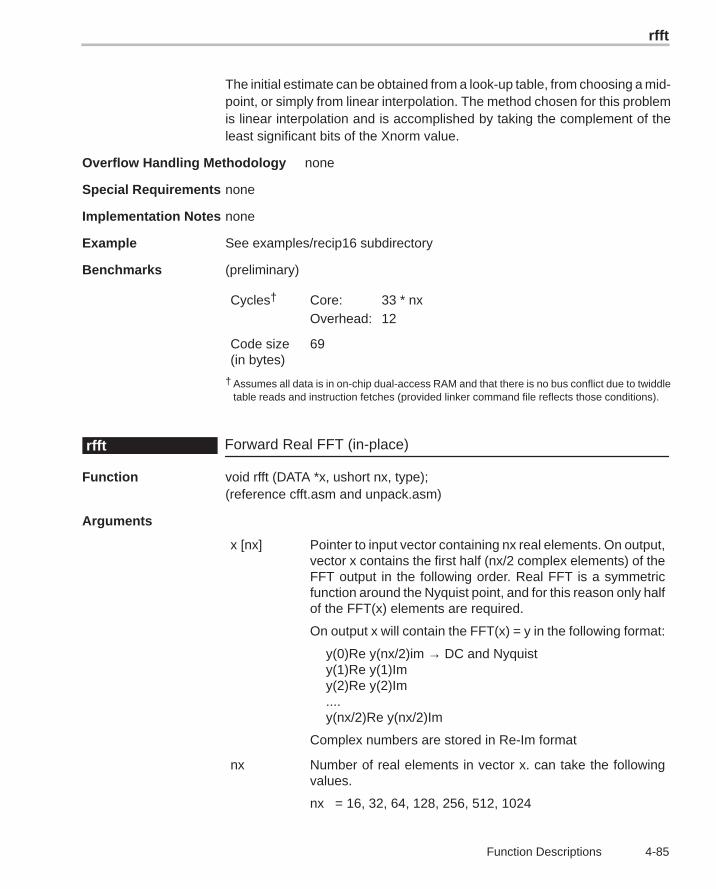
rfft
4-85 Function Descriptions
The initial estimate can be obtained from a look-up table, from choosing a mid-point, or simply from linear interpolation. The method chosen for this problemis linear interpolation and is accomplished by taking the complement of theleast significant bits of the Xnorm value.
Overflow Handling Methodology none
Special Requirements none
Implementation Notes none
Example See examples/recip16 subdirectory
Benchmarks (preliminary)
Cycles† Core: 33 * nxOverhead: 12
Code size(in bytes)
69
† Assumes all data is in on-chip dual-access RAM and that there is no bus conflict due to twiddletable reads and instruction fetches (provided linker command file reflects those conditions).
Forward Real FFT (in-place)rfft
Function void rfft (DATA *x, ushort nx, type);(reference cfft.asm and unpack.asm)
Arguments
x [nx] Pointer to input vector containing nx real elements. On output,vector x contains the first half (nx/2 complex elements) of theFFT output in the following order. Real FFT is a symmetricfunction around the Nyquist point, and for this reason only halfof the FFT(x) elements are required.
On output x will contain the FFT(x) = y in the following format:
y(0)Re y(nx/2)im → DC and Nyquisty(1)Re y(1)Imy(2)Re y(2)Im....y(nx/2)Re y(nx/2)Im
Complex numbers are stored in Re-Im format
nx Number of real elements in vector x. can take the followingvalues.
nx = 16, 32, 64, 128, 256, 512, 1024
rfft
4-86
type RFFT type selector. Types supported:
� If type = SCALE, scaled version selected
� If type = NOSCALE, non-scaled version selected
Description Computes a Radix-2 real DIT FFT of the nx real elements stored in vector xin bit-reversed order. The original content of vector x is destroyed in theprocess. The first nx/2 complex elements of the FFT(x) are stored in vector xin normal-order.
Algorithm (DFT)See CFFT
Special Requirements� This function should work with unpack.asm and/or rfft.asm for proper
result. See example in examples/rifft directory.
� Memory alignment: input data (x) must be aligned at even word boundary.
� Data memory alignment (referenced rfft.cmd in examples/rfft directory):
� Alignment of input database address: (n+1) LSBs must be zeros,where n = log2(nx).
� Ensure that the entire array fits within a 64K boundary (the largest pos-sible array addressable by the 16-bit auxiliary register).
� For best performance, the data buffer has to be in a DARAM block.
� If the twiddle table and the data buffer are in the same block, then theradix-2 kernel is 7 cycles and the radix-4 kernel is not affected.
� The twiddle table should be aligned to the nx word boundary; i.e., thelowest log2(nx) least significant bits of the twiddle table starting ad-dress should be zero.
Implementation Notes Implemented as a complex FFT of size nx/2 followed by an unpack stage tounpack the real FFT results. Therefore, Implementation Notes for the cfft func-tion apply to this case.
Notice that normally an FFT of a real sequence of size N, produces a complexsequence of size N (or 2*N real numbers) that will not fit in the input sequence.To accommodate all the results without requiring extra memory locations, theoutput reflects only half of the spectrum (complex output). This still providesthe full information because an FFT of a real sequence has even symmetryaround the center or nyquist point(N/2).
When scale = 1, this routine prevents overflow by scaling by 2 at each FFTintermediate stages and at the unpacking stage.
Example See examples/rfft Zip file
rifft
4-87 Function Descriptions
Inverse Real FFT (in-place)rifft
Function void rifft (DATA *x, ushort nx, type);(reference cifft.asm)
Arguments
x [nx] Pointer to input vector x containing nx real elements. Theunpacki routine should be called to unpack the rfft sequencebefore calling the bit reversal routine. (See examples directoryfor calling sequence)
On output, the vector x contains nx complex elementscorresponding to RIFFT(x) or the signal itself.
nx Number of real elements in vector x. nx can take the followingvalues.
nx =16, 32, 64, 128, 256, 512, 1024
type RFFT type selector. Types supported:
� If type = SCALE, scaled version selected
� If type = NOSCALE, non-scaled version selected
Description Computes a Radix-2 real DIT IFFT of the nx real elements stored in vector xin bit-reversed order. The original content of vector x is destroyed in theprocess. The first nx/2 complex elements of the IFFT(x) are stored in vectorx in normal-order.
Algorithm (IDFT)See CIFFT
Special Requirements� This function should work with unpacki.asm and/or cbrev.asm for proper
result. See example in examples/rifft directory.
� Memory alignment: input data (x) must be aligned at even word boundary.
� Data memory alignment (referenced rfft.cmd in examples/rfft directory):
� Alignment of input database address: (n+1) LSBs must be zeros,where n = log2(nx).
� Ensure that the entire array fits within a 64K boundary (the largest pos-sible array addressable by the 16-bit auxiliary register).
� For best performance, the data buffer has to be in a DARAM block.
� If the twiddle table and the data buffer are in the same block, then theradix-2 kernel is 7 cycles and the radix-4 kernel is not affected.
sine
4-88
� The twiddle table should be aligned to the nx word boundary; i.e., thelowest log2(nx) least significant bits of the twiddle table starting ad-dress should be zero.
Implementation Notes Implemented as a complex IFFT of size nx/2 followed by an unpack stage tounpack the real IFFT results. Therefore, Implementation Notes for the cfftfunction apply to this case.
Notice that normally an IFFT of a real sequence of size N, produces a complexsequence of size N (or 2*N real numbers) that will not fit in the input sequence.To accommodate all the results without requiring extra memory locations, theoutput reflects only half of the spectrum (complex output). This still providesthe full information because an IFFT of a real sequence has even symmetryaround the center or nyquist point(N/2).
When scale = 1, this routine prevents overflow by scaling by 2 at each IFFTintermediate stages and at the unpacking stage.
Example See examples/rifft subdirectory
Sinesine
Function ushort oflag = sine (DATA *x, DATA *r, ushort nx) (defined in sine.asm)
Arguments
x[nx] Pointer to input vector of size nx. x contains the angle inradians between [–pi, pi] normalized between (–1,1) in q15formatx = xrad /piFor example:45o = pi/4 is equivalent to x = 1/4 = 0.25 = 0x200 in q15format.
r[nx] Pointer to output vector containing the sine of vector x inq15 format
nx Number of elements of input and output vectors.nx ≥ 4
oflag Overflow flag.
� If oflag = 1, a 32-bit overflow has occurred.
� If oflag = 0, a 32-bit overflow has not occurred.
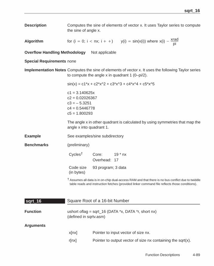
sqrt_16
4-89 Function Descriptions
Description Computes the sine of elements of vector x. It uses Taylor series to computethe sine of angle x.
Algorithm for (i � 0; i � nx; i ��) y(i) � sin(x(i)) where x(i) � xradpi
Overflow Handling Methodology Not applicable
Special Requirements none
Implementation Notes Computes the sine of elements of vector x. It uses the following Taylor seriesto compute the angle x in quadrant 1 (0–pi/2).
sin(x) = c1*x + c2*x^2 + c3*x^3 + c4*x^4 + c5*x^5
c1 = 3.140625xc2 = 0.02026367c3 = – 5.3251c4 = 0.5446778c5 = 1.800293
The angle x in other quadrant is calculated by using symmetries that map theangle x into quadrant 1.
Example See examples/sine subdirectory
Benchmarks (preliminary)
Cycles† Core: 19 * nxOverhead: 17
Code size(in bytes)
93 program; 3 data
† Assumes all data is in on-chip dual-access RAM and that there is no bus conflict due to twiddletable reads and instruction fetches (provided linker command file reflects those conditions).
Square Root of a 16-bit Numbersqrt_16
Function ushort oflag = sqrt_16 (DATA *x, DATA *r, short nx)(defined in sqrtv.asm)
Arguments
x[nx] Pointer to input vector of size nx.
r[nx] Pointer to output vector of size nx containing the sqrt(x).
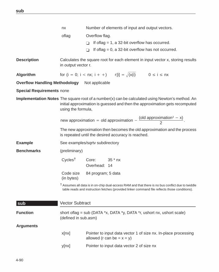
sub
4-90
nx Number of elements of input and output vectors.
oflag Overflow flag.
� If oflag = 1, a 32-bit overflow has occurred.
� If oflag = 0, a 32-bit overflow has not occurred.
Description Calculates the square root for each element in input vector x, storing resultsin output vector r.
Algorithm for (i � 0; i � nx; i ��) r [i] � (x(i) 0 � i � nx
Overflow Handling Methodology Not applicable
Special Requirements none
Implementation Notes The square root of a number(x) can be calculated using Newton’s method. Aninitial approximation is guessed and then the approximation gets recomputedusing the formula,
new approximation � old approximation �(old approximation2 � x)
2.
The new approximation then becomes the old approximation and the processis repeated until the desired accuracy is reached.
Example See examples/sqrtv subdirectory
Benchmarks (preliminary)
Cycles† Core: 35 * nxOverhead: 14
Code size(in bytes)
84 program; 5 data
† Assumes all data is in on-chip dual-access RAM and that there is no bus conflict due to twiddletable reads and instruction fetches (provided linker command file reflects those conditions).
Vector Subtractsub
Function short oflag = sub (DATA *x, DATA *y, DATA *r, ushort nx, ushort scale)(defined in sub.asm)
Arguments
x[nx] Pointer to input data vector 1 of size nx. In-place processingallowed (r can be = x = y)
y[nx] Pointer to input data vector 2 of size nx
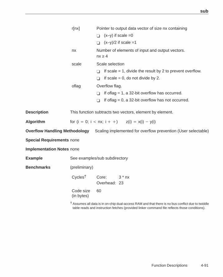
sub
4-91 Function Descriptions
r[nx] Pointer to output data vector of size nx containing
� (x–y) if scale =0
� (x–y)/2 if scale =1
nx Number of elements of input and output vectors.nx ≥ 4
scale Scale selection
� If scale = 1, divide the result by 2 to prevent overflow.
� If scale = 0, do not divide by 2.
oflag Overflow flag.
� If oflag = 1, a 32-bit overflow has occurred.
� If oflag = 0, a 32-bit overflow has not occurred.
Description This function subtracts two vectors, element by element.
Algorithm for (i � 0; i � nx; i ��) z(i) � x(i) � y(i)
Overflow Handling Methodology Scaling implemented for overflow prevention (User selectable)
Special Requirements none
Implementation Notes none
Example See examples/sub subdirectory
Benchmarks (preliminary)
Cycles† Core: 3 * nxOverhead: 23
Code size(in bytes)
60
† Assumes all data is in on-chip dual-access RAM and that there is no bus conflict due to twiddletable reads and instruction fetches (provided linker command file reflects those conditions).
5-1
DSPLIB Benchmarks and Performance Issues
All functions in the DSPLIB are provided with execution time and code sizebenchmarks. While developing the included functions, we tried to compromisebetween speed, code size, and ease of use. However, with few exceptions, thehighest priority was given to optimize for speed and ease of use, and last forcode size.
Even though DSPLIB can be used as a first estimation of processor perfor-mance for a specific function, you should know that the generic nature ofDSPLIB may add extra cycles not required for customer specific usage.
Topic Page
5.1 What DSPLIB Benchmarks are Provided 5-2. . . . . . . . . . . . . . . . . . . . . . . .
5.2 Performance Considerations 5-2. . . . . . . . . . . . . . . . . . . . . . . . . . . . . . . . . . .
Chapter 5
What DSPLIB Benchmarks are Provided
5-2
5.1 What DSPLIB Benchmarks are Provided
DSPLIB documentation includes benchmarks for instruction cycles andmemory consumption. The following benchmarks are typically included:
� Calling and register initialization overhead
� Number of cycles in the kernel code: Typically provided in the form of anequation that is a function of the data size parameters. We consider thekernel (or core) code, the instructions contained between the _start and_end labels that you can see in each of the functions.
� Memory consumption: Typically program size in bytes is reported. Forfunctions requiring significant internal data allocation, data memory con-sumption is also provided. When stack usage for local variables is mini-mum, that data consumption is not reported.
For functions in which it is difficult to determine the number of cycles in the ker-nel code as a function of the data size parameters, we have included directcycle count for specific data sizes.
5.2 Performance Considerations
Benchmark cycles presented assume best case conditions, typically assum-ing:
� 0 wait-state memory external memory for program and data
� data allocation to on-chip DARAM
� no pipeline hits
A linker command file showing the memory allocation used during testing andbenchmarking in the Code Composer C55x Simulator is included under theexample subdirectory.
Remember, execution speed in a system is dependent on where the differentsections of program and data are located in memory. Be sure to account forsuch differences, when trying to explain why a routine is taking more time thatthe reported DSPLIB benchmarks.
What DSPLIB Benchmarks are Provided / Performance Considerations
6-1
Software Updates and Customer Support
This chapter details the software updates and customer support issues for theTMS320C55x DSPLIB.
Topic Page
6.1 DSPLIB Software Updates 6-2. . . . . . . . . . . . . . . . . . . . . . . . . . . . . . . . . . . . .
6.2 DSPLIB Customer Support 6-2. . . . . . . . . . . . . . . . . . . . . . . . . . . . . . . . . . . .
Chapter 6
DSPLIB Software Updates
6-2
6.1 DSPLIB Software Updates
C54x DSPLIB software updates will be periodically released, incorporatingproduct enhancement and fixes.
DSPLIB software updates will be posted as they become available in the samelocation you download this information. Source code for previous releases willbe kept public to prevent any customer problem in case we decide to discontin-ue or change the functionality of one of the DSPLIB functions. Make sure toread the readme.1st file available in the root directory of every release.
6.2 DSPLIB Customer Support
If you have question or want to report problems or suggestions regarding theC54x DSPLIB, contact Texas Instruments at [email protected]. We encourage theuse of the software report form (report.txt) contained in the DSPLIB doc direc-tory to report any problem associated with the C54xDSPLIB.
A-1
Appendix A
Overview of Fractional Q Formats
Unless specifically noted, DSPLIB functions use Q15 format or to be more ex-act Q0.15. In a Qm.n format, there are m bits used to represent the two’s com-plement integer portion of the number, and n bits used to represent the two’scomplement fractional portion. m+n+1 bits are needed to store a general Qm.nnumber. The extra bit is needed to store the sign of the number in the most-sig-nificant bit position. The representable integer range is specified by (–2m, 2m)and the finest fractional resolution is 2�n .
For example, the most commonly used format is Q.15. Q.15 means that a16-bit word is used to express a signed number between positive and negative1. The most-significant binary digit is interpreted as the sign bit in any Q formatnumber. Thus in Q.15 format, the decimal point is placed immediately to theright of the sign bit. The fractional portion to the right of the sign bit is storedin regular two’s complement format.
Topic Page
A.1 Q3.12 Format A-2. . . . . . . . . . . . . . . . . . . . . . . . . . . . . . . . . . . . . . . . . . . . . . . . .
A.2 Q.15 Format A-2. . . . . . . . . . . . . . . . . . . . . . . . . . . . . . . . . . . . . . . . . . . . . . . . . .
A.3 Q.31 Format A-2. . . . . . . . . . . . . . . . . . . . . . . . . . . . . . . . . . . . . . . . . . . . . . . . . .
Appendix A
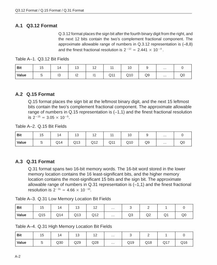
Q3.12 Format
A-2
A.1 Q3.12 Format
Q.3.12 format places the sign bit after the fourth binary digit from the right, andthe next 12 bits contain the two’s complement fractional component. Theapproximate allowable range of numbers in Q.3.12 representation is (–8,8)and the finest fractional resolution is 2�12 � 2.441 � 10�4 .
Table A–1. Q3.12 Bit Fields
Bit 15 14 13 12 11 10 9 … 0
Value S I3 I2 I1 Q11 Q10 Q9 … Q0
A.2 Q.15 Format
Q.15 format places the sign bit at the leftmost binary digit, and the next 15 leftmostbits contain the two’s complement fractional component. The approximate allowablerange of numbers in Q.15 representation is (–1,1) and the finest fractional resolutionis 2�15 � 3.05 � 10�5.
Table A–2. Q.15 Bit Fields
Bit 15 14 13 12 11 10 9 … 0
Value S Q14 Q13 Q12 Q11 Q10 Q9 … Q0
A.3 Q.31 Format
Q.31 format spans two 16-bit memory words. The 16-bit word stored in the lowermemory location contains the 16 least-significant bits, and the higher memorylocation contains the most-significant 15 bits and the sign bit. The approximateallowable range of numbers in Q.31 representation is (–1,1) and the finest fractionalresolution is 2�31 � 4.66 � 10�10.
Table A–3. Q.31 Low Memory Location Bit Fields
Bit 15 14 13 12 … 3 2 1 0
Value Q15 Q14 Q13 Q12 … Q3 Q2 Q1 Q0
Table A–4. Q.31 High Memory Location Bit Fields
Bit 15 14 13 12 … 3 2 1 0
Value S Q30 Q29 Q28 … Q19 Q18 Q17 Q16
Q3.12 Format / Q.15 Format / Q.31 Format
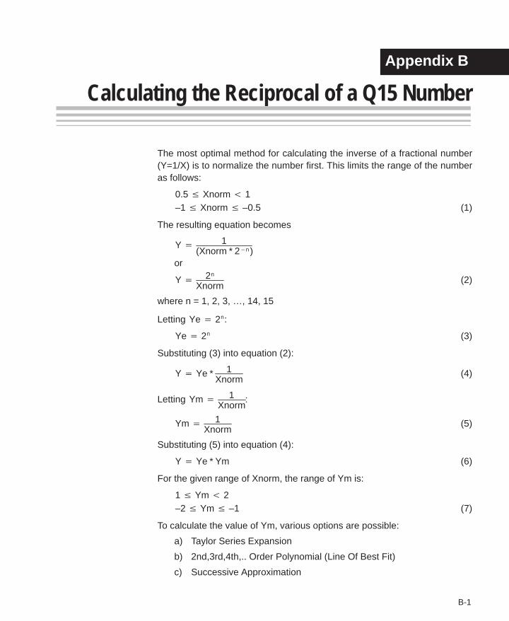
B-1
Appendix A
Calculating the Reciprocal of a Q15 Number
The most optimal method for calculating the inverse of a fractional number(Y=1/X) is to normalize the number first. This limits the range of the numberas follows:
0.5 � Xnorm � 1–1 � Xnorm � –0.5 (1)
The resulting equation becomes
Y � 1(Xnorm * 2�n )
or
Y � 2n
Xnorm(2)
where n = 1, 2, 3, …, 14, 15
Letting Ye � 2n:
Ye � 2n (3)
Substituting (3) into equation (2):
Y � Ye * 1Xnorm
(4)
Letting Ym � 1Xnorm
:
Ym � 1Xnorm
(5)
Substituting (5) into equation (4):
Y � Ye * Ym (6)
For the given range of Xnorm, the range of Ym is:
1 � Ym � 2–2 � Ym � –1 (7)
To calculate the value of Ym, various options are possible:
a) Taylor Series Expansion
b) 2nd,3rd,4th,.. Order Polynomial (Line Of Best Fit)
c) Successive Approximation
Appendix B
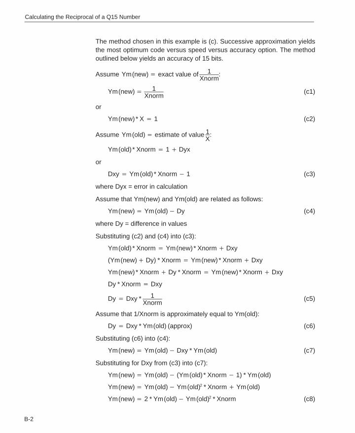
B-2
The method chosen in this example is (c). Successive approximation yieldsthe most optimum code versus speed versus accuracy option. The methodoutlined below yields an accuracy of 15 bits.
Assume Ym (new)� exact value of 1Xnorm
:
Ym (new)� 1Xnorm
(c1)
or
Ym (new) * X � 1 (c2)
Assume Ym (old)� estimate of value 1X
:
Ym (old) * Xnorm � 1 � Dyx
or
Dxy � Ym (old) * Xnorm � 1 (c3)
where Dyx = error in calculation
Assume that Ym(new) and Ym(old) are related as follows:
Ym (new)� Ym (old)� Dy (c4)
where Dy = difference in values
Substituting (c2) and (c4) into (c3):
Ym (old) * Xnorm � Ym(new) * Xnorm � Dxy
(Ym (new)� Dy) * Xnorm � Ym (new) * Xnorm � Dxy
Ym (new) * Xnorm � Dy * Xnorm � Ym (new) * Xnorm � Dxy
Dy * Xnorm � Dxy
Dy � Dxy * 1Xnorm
(c5)
Assume that 1/Xnorm is approximately equal to Ym(old):
Dy � Dxy * Ym (old) (approx) (c6)
Substituting (c6) into (c4):
Ym (new)� Ym (old)� Dxy * Ym (old) (c7)
Substituting for Dxy from (c3) into (c7):
Ym (new)� Ym (old)� (Ym (old) * Xnorm � 1) * Ym(old)
Ym (new)� Ym (old)� Ym (old)2 * Xnorm � Ym (old)
Ym (new)� 2 * Ym (old)� Ym (old)2 * Xnorm (c8)
Calculating the Reciprocal of a Q15 Number
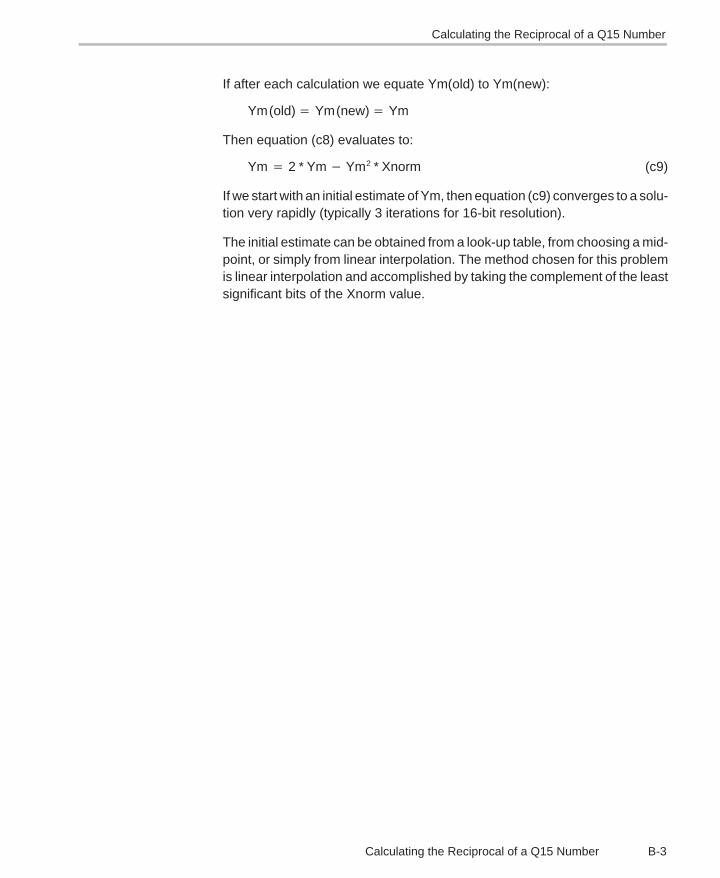
B-3Calculating the Reciprocal of a Q15 Number
If after each calculation we equate Ym(old) to Ym(new):
Ym (old)� Ym (new)� Ym
Then equation (c8) evaluates to:
Ym � 2 * Ym � Ym2 * Xnorm (c9)
If we start with an initial estimate of Ym, then equation (c9) converges to a solu-tion very rapidly (typically 3 iterations for 16-bit resolution).
The initial estimate can be obtained from a look-up table, from choosing a mid-point, or simply from linear interpolation. The method chosen for this problemis linear interpolation and accomplished by taking the complement of the leastsignificant bits of the Xnorm value.
Calculating the Reciprocal of a Q15 Number
Index
Index-1
Index
16-bit reciprocal function 4-8432-bit by 16-bit long division function 4-6332-bit vector multiplication 4-76
Aacorr 4-7adaptive delayed LMS filter 4-31add 4-9arctangent 2 implementation 4-10arctangent implementation 4-11atan16 4-11atan2_16 4-10autocorrelation 4-7
Bbase 10 logarithm 4-64base 2 logarithm 4-66base e logarithm 4-67bexp 4-13block exponent implementation 4-13block FIR filter (fast) 4-37
Ccascaded IIR direct form I 4-59cascaded IIR direct form II 4-56, 4-58cbrev 4-14cfft 4-15cfir 4-17cifft 4-21complex bit reverse 4-14complex FIR filter 4-17
conversionfloating-point to Q15 (fltoq15) 4-49Q15 to floating-point (q15tofl) 4-80
convol 4-23
convol1 4-25
convol2 4-27
convolution 4-23
convolution (fast) 4-25
convolution (fastest) 4-27
corr 4-30
correlationauto (acorr) 4-7full-length (corr) 4-30
correlation (full-length) 4-30
Ddecimating FIR filter 4-40
dlms 4-31
double-precision IIR filter 4-53
DSPLIBarguments 3-2calling a function from assembly language source
code 3-5calling a function from C 3-3content 2-2data types 3-2dealing with overflow and scaling issues 3-6how to install 2-2how to rebuild 2-3
Eexpn 4-33
exponential base e 4-33
Index
Index-2
FFFT
forward complex (cfft) 4-15forward real, in-place (rfft) 4-85inverse complex (cifft) 4-21inverse real, in-place (rifft) 4-87
fir 4-34
FIR filter 4-34block filter, fast (fir2) 4-37complex (cfir) 4-17decimating (firdec) 4-40direct form (fir) 4-34Hilbert Transformer 4-50interpolating (firinterp) 4-42lattice forward (firlat) 4-44symmetric (firs) 4-46
FIR Hilbert Transformer 4-50
fir2 4-37
firdec 4-40
firinterp 4-42
firlat 4-44
firs 4-46
floating-point to Q15 conversion 4-49
fltoq15 4-49
forward complex FFT 4-15
forward real FFT (in-place) 4-85
Hhilb16 4-50
IIIR filter
cascaded, direct form I (iircas51) 4-59cascaded, direct form II (iircas4) 4-56cascaded, direct form II (iircas5) 4-58double-precision (iir32) 4-53lattice inverse (iirlat) 4-61
iir32 4-53
iircas4 4-56
iircas5 4-58
iircas51 4-59
iirlat 4-61
index and value of maximum element of avector 4-71
index and value of minimum element of avector 4-73
index of maximum element of a vector 4-69index of maximum element of a vector less than or
equal to 34 4-70index of minimum element of a vector 4-72interpolating FIR filter 4-42inverse complex FFT 4-21inverse real FFT (in-place) 4-87
Llattice forward (FIR) filter 4-44lattice inverse (IIR) filter 4-61ldiv16 4-63log_10 4-64log_2 4-66logarithm
base 10 (log_10) 4-64base 2 (log_2) 4-66base e (logn) 4-67
logn 4-67
Mmatrix multiplication 4-74matrix transpose 4-76maxidx 4-69maxidx34 4-70maximum element of a vector
index (maxidx) 4-69index and value (maxvec) 4-71
maximum element of a vector less than or equal to34, index (maxidx34) 4-70
maximum value of a vector 4-70maxval 4-70maxvec 4-71minidx 4-72minimum element of a vector
index (minidx) 4-72index and value (minvec) 4-73
minimum value of a vector 4-73minval 4-73minvec 4-73
Index
Index-3
mmul 4-74mtrans 4-76mul32 4-76
Nnatural logarithm (logn) 4-67neg 4-77neg32 4-78
Ppower 4-79
QQ15 to floating-point conversion 4-80q15tofl 4-80
Rrand16 4-81rand16init 4-83
random number generationalgorithm 4-81initialization 4-83
recip16 4-84
rfft 4-85
rifft 4-87
Ssine 4-88
sqrt_16 4-89
square root of a 16-bit number 4-89
sub 4-90
symmetric FIR filter 4-46
Vvector add 4-9
vector negate 4-77
vector negate, double-precision 4-78
vector power 4-79
vector subtract 4-90