Embed Size (px)
Citation preview

TMS320C54x DSP LibraryProgrammer’s Reference
Literature Number: SPRU518DOctober 2004
Printed on Recycled Paper
IMPORTANT NOTICE
Texas Instruments Incorporated and its subsidiaries (TI) reserve the right to make corrections,modifications, enhancements, improvements, and other changes to its products and services atany time and to discontinue any product or service without notice. Customers should obtain thelatest relevant information before placing orders and should verify that such information is currentand complete. All products are sold subject to TI�s terms and conditions of sale supplied at thetime of order acknowledgment.
TI warrants performance of its hardware products to the specifications applicable at the time ofsale in accordance with TI�s standard warranty. Testing and other quality control techniques areused to the extent TI deems necessary to support this warranty. Except where mandated bygovernment requirements, testing of all parameters of each product is not necessarily performed.
TI assumes no liability for applications assistance or customer product design. Customers areresponsible for their products and applications using TI components. To minimize the risksassociated with customer products and applications, customers should provide adequate designand operating safeguards.
TI does not warrant or represent that any license, either express or implied, is granted under anyTI patent right, copyright, mask work right, or other TI intellectual property right relating to anycombination, machine, or process in which TI products or services are used. Informationpublished by TI regarding third party products or services does not constitute a license from TIto use such products or services or a warranty or endorsement thereof. Use of such informationmay require a license from a third party under the patents or other intellectual property of that thirdparty, or a license from TI under the patents or other intellectual property of TI.
Reproduction of information in TI data books or data sheets is permissible only if reproductionis without alteration and is accompanied by all associated warranties, conditions, limitations, andnotices. Reproduction of this information with alteration is an unfair and deceptive businesspractice. TI is not responsible or liable for such altered documentation.
Resale of TI products or services with statements different from or beyond the parameters statedby TI for that product or service voids all express and any implied warranties for the associatedTI product or service and is an unfair and deceptive business practice. TI is not responsible orliable for any such statements.
Mailing Address:
Texas InstrumentsPost Office Box 655303Dallas, Texas 75265
Copyright 2002, Texas Instruments Incorporated
iiiRead This First
Preface
Read This First
About This Manual
The TMS320C54x DSPLIB is an optimized DSP Function Library for C pro-grammers on TMS320C54x devices. It includes over 50 C-callable assembly-optimized general-purpose signal processing routines. These routines aretypically used in computationally intensive real-time applications where opti-mal execution speed is critical. By using these routines you can achieve exe-cution speeds considerably faster than equivalent code written in standardANSI C language. In addition to providing ready-to-use DSP functions,TI DSPLIB can significantly shorten your DSP application development time.
Related Documentation
� The MathWorks, Inc. Matlab Signal Processing Toolbox User�s Guide.Natick, MA: The MathWorks, Inc., 1996.
� Lehmer, D.H. �Mathematical Methods in large-scale computing units.�Proc. 2nd Sympos. on Large-Scale Digital Calculating Machinery, Cam-bridge, MA, 1949. Cambridge, MA: Harvard University Press, 1951.
� Oppenheim, Alan V. and Ronald W Schafer. Discrete-Time Signal Proc-essing. Englewood Cliffs, NJ: Prentice Hall, 1989.
� Digital Signal Processing with the TMS320 Family (SPR012)
� TMS320C54x DSP CPU and Peripherals Reference Set, Volume 1(SPRU131)
� TMS320C54x Optimizing C Compiler User�s Guide (SPRU103)
Trademarks
TMS320, TMS320C54x, and C54x are trademarks of Texas Instruments.
Matlab is a registered trademark of The MathWorks, Inc.

iv
Contents
v
Contents
1 Introduction 1-1. . . . . . . . . . . . . . . . . . . . . . . . . . . . . . . . . . . . . . . . . . . . . . . . . . . . . . . . . . . . . . . . . . . . . Introduction to the TMS320C54x DSP Library.
1.1 DSP Routines 1-2. . . . . . . . . . . . . . . . . . . . . . . . . . . . . . . . . . . . . . . . . . . . . . . . . . . . . . . . . . . . . . 1.2 Features and Benefits 1-2. . . . . . . . . . . . . . . . . . . . . . . . . . . . . . . . . . . . . . . . . . . . . . . . . . . . . . .
1.2.1 DSPLIB: Quality Freeware That You Can Build on and Contribute to 1-2. . . . . . .
2 Installing DSPLIB 2-1. . . . . . . . . . . . . . . . . . . . . . . . . . . . . . . . . . . . . . . . . . . . . . . . . . . . . . . . . . . . . . . . Describes how to install the DSPLIB.
2.1 DSPLIB Content 2-2. . . . . . . . . . . . . . . . . . . . . . . . . . . . . . . . . . . . . . . . . . . . . . . . . . . . . . . . . . . . 2.2 How to Install DSPLIB 2-3. . . . . . . . . . . . . . . . . . . . . . . . . . . . . . . . . . . . . . . . . . . . . . . . . . . . . . .
2.2.1 De-Archive DSPLIB 2-3. . . . . . . . . . . . . . . . . . . . . . . . . . . . . . . . . . . . . . . . . . . . . . . . . . 2.2.2 Update Your C_DIR Environment Variable 2-3. . . . . . . . . . . . . . . . . . . . . . . . . . . . . .
2.3 How to Rebuild DSPLIB 2-4. . . . . . . . . . . . . . . . . . . . . . . . . . . . . . . . . . . . . . . . . . . . . . . . . . . . . 2.3.1 For Full Rebuild of 54xdsp.lib and/or 54xdspf.lib 2-4. . . . . . . . . . . . . . . . . . . . . . . . . 2.3.2 For Partial Rebuild of 54xdsp.lib and/or 54xdspf.lib (Modification of
a Specific DSPLIB Function, for example fir.asm) 2-4. . . . . . . . . . . . . . . . . . . . . . . .
3 Using DSPLIB 3-1. . . . . . . . . . . . . . . . . . . . . . . . . . . . . . . . . . . . . . . . . . . . . . . . . . . . . . . . . . . . . . . . . . . Describes how to use the DSPLIB.
3.1 DSPLIB Data Types 3-2. . . . . . . . . . . . . . . . . . . . . . . . . . . . . . . . . . . . . . . . . . . . . . . . . . . . . . . . . 3.2 DSPLIB Arguments 3-2. . . . . . . . . . . . . . . . . . . . . . . . . . . . . . . . . . . . . . . . . . . . . . . . . . . . . . . . . 3.3 Calling a DSPLIB Function from C 3-3. . . . . . . . . . . . . . . . . . . . . . . . . . . . . . . . . . . . . . . . . . . . 3.4 Calling a DSPLIB Function from Assembly 3-4. . . . . . . . . . . . . . . . . . . . . . . . . . . . . . . . . . . . . 3.5 Where to Find Sample Code 3-4. . . . . . . . . . . . . . . . . . . . . . . . . . . . . . . . . . . . . . . . . . . . . . . . . 3.6 How DSPLIB is Tested � Allowable Error 3-5. . . . . . . . . . . . . . . . . . . . . . . . . . . . . . . . . . . . . . 3.7 How DSPLIB Deals With Overflow and Scaling Issues 3-5. . . . . . . . . . . . . . . . . . . . . . . . . . . 3.8 Where DSPLIB Goes From Here 3-7. . . . . . . . . . . . . . . . . . . . . . . . . . . . . . . . . . . . . . . . . . . . .
4 Function Descriptions 4-1. . . . . . . . . . . . . . . . . . . . . . . . . . . . . . . . . . . . . . . . . . . . . . . . . . . . . . . . . . . Provides descriptions for the TMS330C55x DSPLIB functions.
4.1 Arguments and Conventions Used 4-2. . . . . . . . . . . . . . . . . . . . . . . . . . . . . . . . . . . . . . . . . . . . 4.2 DSPLIB Functions 4-3. . . . . . . . . . . . . . . . . . . . . . . . . . . . . . . . . . . . . . . . . . . . . . . . . . . . . . . . . .
acorr 4-7. . . . . . . . . . . . . . . . . . . . . . . . . . . . . . . . . . . . . . . . . . . . . . . . . . . . . . . . . . . . . . . . . . . . . . add 4-8. . . . . . . . . . . . . . . . . . . . . . . . . . . . . . . . . . . . . . . . . . . . . . . . . . . . . . . . . . . . . . . . . . . . . . . atan16 4-9. . . . . . . . . . . . . . . . . . . . . . . . . . . . . . . . . . . . . . . . . . . . . . . . . . . . . . . . . . . . . . . . . . . .
Contents
vi
atan2_16 4-10. . . . . . . . . . . . . . . . . . . . . . . . . . . . . . . . . . . . . . . . . . . . . . . . . . . . . . . . . . . . . . . . . bexp 4-11. . . . . . . . . . . . . . . . . . . . . . . . . . . . . . . . . . . . . . . . . . . . . . . . . . . . . . . . . . . . . . . . . . . . . cbrev 4-12. . . . . . . . . . . . . . . . . . . . . . . . . . . . . . . . . . . . . . . . . . . . . . . . . . . . . . . . . . . . . . . . . . . . . cfir 4-14. . . . . . . . . . . . . . . . . . . . . . . . . . . . . . . . . . . . . . . . . . . . . . . . . . . . . . . . . . . . . . . . . . . . . . . cfft 4-15. . . . . . . . . . . . . . . . . . . . . . . . . . . . . . . . . . . . . . . . . . . . . . . . . . . . . . . . . . . . . . . . . . . . . . . cfft32 4-17. . . . . . . . . . . . . . . . . . . . . . . . . . . . . . . . . . . . . . . . . . . . . . . . . . . . . . . . . . . . . . . . . . . . . cifft 4-19. . . . . . . . . . . . . . . . . . . . . . . . . . . . . . . . . . . . . . . . . . . . . . . . . . . . . . . . . . . . . . . . . . . . . . cifft32 4-21. . . . . . . . . . . . . . . . . . . . . . . . . . . . . . . . . . . . . . . . . . . . . . . . . . . . . . . . . . . . . . . . . . . . convol 4-23. . . . . . . . . . . . . . . . . . . . . . . . . . . . . . . . . . . . . . . . . . . . . . . . . . . . . . . . . . . . . . . . . . . . corr 4-24. . . . . . . . . . . . . . . . . . . . . . . . . . . . . . . . . . . . . . . . . . . . . . . . . . . . . . . . . . . . . . . . . . . . . . dlms 4-26. . . . . . . . . . . . . . . . . . . . . . . . . . . . . . . . . . . . . . . . . . . . . . . . . . . . . . . . . . . . . . . . . . . . . expn 4-27. . . . . . . . . . . . . . . . . . . . . . . . . . . . . . . . . . . . . . . . . . . . . . . . . . . . . . . . . . . . . . . . . . . . . fir 4-28. . . . . . . . . . . . . . . . . . . . . . . . . . . . . . . . . . . . . . . . . . . . . . . . . . . . . . . . . . . . . . . . . . . . . . . . firdec 4-30. . . . . . . . . . . . . . . . . . . . . . . . . . . . . . . . . . . . . . . . . . . . . . . . . . . . . . . . . . . . . . . . . . . . . firinterp 4-31. . . . . . . . . . . . . . . . . . . . . . . . . . . . . . . . . . . . . . . . . . . . . . . . . . . . . . . . . . . . . . . . . . . firs 4-33. . . . . . . . . . . . . . . . . . . . . . . . . . . . . . . . . . . . . . . . . . . . . . . . . . . . . . . . . . . . . . . . . . . . . . . firs2 4-34. . . . . . . . . . . . . . . . . . . . . . . . . . . . . . . . . . . . . . . . . . . . . . . . . . . . . . . . . . . . . . . . . . . . . . fltoq15 4-36. . . . . . . . . . . . . . . . . . . . . . . . . . . . . . . . . . . . . . . . . . . . . . . . . . . . . . . . . . . . . . . . . . . hilb16 4-37. . . . . . . . . . . . . . . . . . . . . . . . . . . . . . . . . . . . . . . . . . . . . . . . . . . . . . . . . . . . . . . . . . . . iir32 4-38. . . . . . . . . . . . . . . . . . . . . . . . . . . . . . . . . . . . . . . . . . . . . . . . . . . . . . . . . . . . . . . . . . . . . . iircas4 4-40. . . . . . . . . . . . . . . . . . . . . . . . . . . . . . . . . . . . . . . . . . . . . . . . . . . . . . . . . . . . . . . . . . . . iircas5 4-42. . . . . . . . . . . . . . . . . . . . . . . . . . . . . . . . . . . . . . . . . . . . . . . . . . . . . . . . . . . . . . . . . . . . iircas51 4-44. . . . . . . . . . . . . . . . . . . . . . . . . . . . . . . . . . . . . . . . . . . . . . . . . . . . . . . . . . . . . . . . . . . iirlat 4-45. . . . . . . . . . . . . . . . . . . . . . . . . . . . . . . . . . . . . . . . . . . . . . . . . . . . . . . . . . . . . . . . . . . . . . firlat 4-47. . . . . . . . . . . . . . . . . . . . . . . . . . . . . . . . . . . . . . . . . . . . . . . . . . . . . . . . . . . . . . . . . . . . . . log_2 4-48. . . . . . . . . . . . . . . . . . . . . . . . . . . . . . . . . . . . . . . . . . . . . . . . . . . . . . . . . . . . . . . . . . . . . log_10 4-50. . . . . . . . . . . . . . . . . . . . . . . . . . . . . . . . . . . . . . . . . . . . . . . . . . . . . . . . . . . . . . . . . . . logn 4-51. . . . . . . . . . . . . . . . . . . . . . . . . . . . . . . . . . . . . . . . . . . . . . . . . . . . . . . . . . . . . . . . . . . . . . maxidx 4-52. . . . . . . . . . . . . . . . . . . . . . . . . . . . . . . . . . . . . . . . . . . . . . . . . . . . . . . . . . . . . . . . . . . maxval 4-53. . . . . . . . . . . . . . . . . . . . . . . . . . . . . . . . . . . . . . . . . . . . . . . . . . . . . . . . . . . . . . . . . . . minidx 4-54. . . . . . . . . . . . . . . . . . . . . . . . . . . . . . . . . . . . . . . . . . . . . . . . . . . . . . . . . . . . . . . . . . . . minval 4-54. . . . . . . . . . . . . . . . . . . . . . . . . . . . . . . . . . . . . . . . . . . . . . . . . . . . . . . . . . . . . . . . . . . . mmul 4-55. . . . . . . . . . . . . . . . . . . . . . . . . . . . . . . . . . . . . . . . . . . . . . . . . . . . . . . . . . . . . . . . . . . . . mtrans 4-56. . . . . . . . . . . . . . . . . . . . . . . . . . . . . . . . . . . . . . . . . . . . . . . . . . . . . . . . . . . . . . . . . . . mul32 4-57. . . . . . . . . . . . . . . . . . . . . . . . . . . . . . . . . . . . . . . . . . . . . . . . . . . . . . . . . . . . . . . . . . . . nblms 4-58. . . . . . . . . . . . . . . . . . . . . . . . . . . . . . . . . . . . . . . . . . . . . . . . . . . . . . . . . . . . . . . . . . . . ndlms 4-60. . . . . . . . . . . . . . . . . . . . . . . . . . . . . . . . . . . . . . . . . . . . . . . . . . . . . . . . . . . . . . . . . . . . neg 4-62. . . . . . . . . . . . . . . . . . . . . . . . . . . . . . . . . . . . . . . . . . . . . . . . . . . . . . . . . . . . . . . . . . . . . . neg32 4-63. . . . . . . . . . . . . . . . . . . . . . . . . . . . . . . . . . . . . . . . . . . . . . . . . . . . . . . . . . . . . . . . . . . . power 4-64. . . . . . . . . . . . . . . . . . . . . . . . . . . . . . . . . . . . . . . . . . . . . . . . . . . . . . . . . . . . . . . . . . . . q15tofl 4-65. . . . . . . . . . . . . . . . . . . . . . . . . . . . . . . . . . . . . . . . . . . . . . . . . . . . . . . . . . . . . . . . . . . rand16init 4-65. . . . . . . . . . . . . . . . . . . . . . . . . . . . . . . . . . . . . . . . . . . . . . . . . . . . . . . . . . . . . . . . . rand16 4-66. . . . . . . . . . . . . . . . . . . . . . . . . . . . . . . . . . . . . . . . . . . . . . . . . . . . . . . . . . . . . . . . . . . recip16 4-67. . . . . . . . . . . . . . . . . . . . . . . . . . . . . . . . . . . . . . . . . . . . . . . . . . . . . . . . . . . . . . . . . . .
Contents
viiContents
rfft 4-68. . . . . . . . . . . . . . . . . . . . . . . . . . . . . . . . . . . . . . . . . . . . . . . . . . . . . . . . . . . . . . . . . . . . . . . rifft 4-70. . . . . . . . . . . . . . . . . . . . . . . . . . . . . . . . . . . . . . . . . . . . . . . . . . . . . . . . . . . . . . . . . . . . . . . sine 4-72. . . . . . . . . . . . . . . . . . . . . . . . . . . . . . . . . . . . . . . . . . . . . . . . . . . . . . . . . . . . . . . . . . . . . . sqrt_16 4-74. . . . . . . . . . . . . . . . . . . . . . . . . . . . . . . . . . . . . . . . . . . . . . . . . . . . . . . . . . . . . . . . . . . sub 4-75. . . . . . . . . . . . . . . . . . . . . . . . . . . . . . . . . . . . . . . . . . . . . . . . . . . . . . . . . . . . . . . . . . . . . .
5 DSPLIB Benchmarks and Performance Issues 5-1. . . . . . . . . . . . . . . . . . . . . . . . . . . . . . . . . . . . . Describes benchmarks and performance issues for the DSPLIB functions.
5.1 What DSPLIB Benchmarks are Provided 5-2. . . . . . . . . . . . . . . . . . . . . . . . . . . . . . . . . . . . . . 5.2 Performance Considerations 5-2. . . . . . . . . . . . . . . . . . . . . . . . . . . . . . . . . . . . . . . . . . . . . . . . .
6 Software Updates and Customer Support 6-1. . . . . . . . . . . . . . . . . . . . . . . . . . . . . . . . . . . . . . . . . Details the software updates and customer support issues for the TMS320C55x DSPLIB.
6.1 DSPLIB Software Updates 6-2. . . . . . . . . . . . . . . . . . . . . . . . . . . . . . . . . . . . . . . . . . . . . . . . . . . 6.2 DSPLIB Customer Support 6-2. . . . . . . . . . . . . . . . . . . . . . . . . . . . . . . . . . . . . . . . . . . . . . . . . .
A Overview of Fractional Q Formats A-1. . . . . . . . . . . . . . . . . . . . . . . . . . . . . . . . . . . . . . . . . . . . . . . . Describes the fractional Q formats used by the DSPLIB functions.A-1
A.1 Q3.12 Format A-2. . . . . . . . . . . . . . . . . . . . . . . . . . . . . . . . . . . . . . . . . . . . . . . . . . . . . . . . . . . . . . A.2 Q.15 Format A-2. . . . . . . . . . . . . . . . . . . . . . . . . . . . . . . . . . . . . . . . . . . . . . . . . . . . . . . . . . . . . . . A.3 Q.31 Format A-2. . . . . . . . . . . . . . . . . . . . . . . . . . . . . . . . . . . . . . . . . . . . . . . . . . . . . . . . . . . . . . .
B Calculating the Reciprocal of a Q15 Number B-1. . . . . . . . . . . . . . . . . . . . . . . . . . . . . . . . . . . . . . . Provides the calculations used to find the inverse of a fractional Q15 number.
Tables
viii
Tables
4−1 Arguments and Conventions 4-2. . . . . . . . . . . . . . . . . . . . . . . . . . . . . . . . . . . . . . . . . . . . . . . . . . . . 4−2 DSPLIB Function Summary Table 4-3. . . . . . . . . . . . . . . . . . . . . . . . . . . . . . . . . . . . . . . . . . . . . . A−1 Q3.12 Bit Fields A-2. . . . . . . . . . . . . . . . . . . . . . . . . . . . . . . . . . . . . . . . . . . . . . . . . . . . . . . . . . . . . . . A−2 Q.15 Bit Fields A-2. . . . . . . . . . . . . . . . . . . . . . . . . . . . . . . . . . . . . . . . . . . . . . . . . . . . . . . . . . . . . . . . A−3 Q.31 Low Memory Location Bit Fields A-2. . . . . . . . . . . . . . . . . . . . . . . . . . . . . . . . . . . . . . . . . . . . A−4 Q.31 High Memory Location Bit Fields A-2. . . . . . . . . . . . . . . . . . . . . . . . . . . . . . . . . . . . . . . . . . .
1-1
Introduction
The TMS320C54x DSP Library (DSPLIB) is an optimized DSP Function Li-brary for C programmers on TMS320C54x devices. It includes over 50 C-call-able assembly-optimized general-purpose signal processing routines. Theseroutines are typically used in computationally intensive real-time applicationswhere optimal execution speed is critical. By using these routines you canachieve execution speeds considerably faster than equivalent code written instandard ANSI C language. In addition to providing ready-to-use DSP func-tions, TI DSPLIB can significantly shorten your DSP application developmenttime.
Topic Page
1.1 DSP Routines 1-2. . . . . . . . . . . . . . . . . . . . . . . . . . . . . . . . . . . . . . . . . . . . . . . . .
1.2 Features and Benefits 1-2. . . . . . . . . . . . . . . . . . . . . . . . . . . . . . . . . . . . . . . . .
Chapter 1
DSP Routines
1-2
1.1 DSP Routines
The TI DSPLIB includes commonly used DSP routines. Source code is pro-vided to allow you to modify the functions to match your specific needs.
The routines included within the library are organized into eight different func-tional categories:
� FFT
� Filtering and convolution
� Adaptive filtering
� Correlation
� Math
� Trigonometric
� Miscellaneous
� Matrix
1.2 Features and Benefits
� Hand-coded assembly optimized routines
� C-callable routines fully compatible with the TI C54x compiler
� Support also provided for C54x devices with extended program memoryaddressing (Far mode)
� Fractional Q15-format operand supported
� Complete set of examples on use provided
� Benchmarks (time and code) provided
� Tested against Matlab scripts
1.2.1 DSPLIB: Quality Freeware That You Can Build on and Contribute to
DSPLIB is a free-of-charge product. You can use, modify, and distribute TIC54x DSPLIB for use on TI C54x DSPs with no royalty payments. Refer tosection 3.8, Where DSPLIB Goes From Here, for details.
2-1
Installing DSPLIB
This chapter describes how to install the DSPLIB.
Topic Page
2.1 DSPLIB Content 2-2. . . . . . . . . . . . . . . . . . . . . . . . . . . . . . . . . . . . . . . . . . . . . .
2.2 How to Install DSPLIB 2-3. . . . . . . . . . . . . . . . . . . . . . . . . . . . . . . . . . . . . . . . .
2.3 How to Rebuild DSPLIB 2-4. . . . . . . . . . . . . . . . . . . . . . . . . . . . . . . . . . . . . . .
Chapter 2
DSPLIB Content
2-2
2.1 DSPLIB Content
The TI DSPLIB software consists of four parts:
1) A header file for C programmers:
dsplib.h
2) Two object libraries for the two different memory models supported by TIcompilers:
54xdsp.lib for standards short-call mode (16-bit)
54xdspf.lib for far-call mode (24-bits)
3) One source library to allow function customization by the end user
54xdsp.src
4) Example programs and linker command files used under the �54x_test�subdirectory.
How to Install DSPLIB
2-3Installing DSPLIB
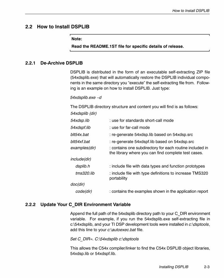
2.2 How to Install DSPLIB
Note:
Read the README.1ST file for specific details of release.
2.2.1 De-Archive DSPLIB
DSPLIB is distributed in the form of an executable self-extracting ZIP file(54xdsplib.exe) that will automatically restore the DSPLIB individual compo-nents in the same directory you �execute� the self-extracting file from. Follow-ing is an example on how to install DSPLIB. Just type:
54xdsplib.exe −d
The DSPLIB directory structure and content you will find is as follows:
54xdsplib (dir)
54xdsp.lib
54xdspf.lib
blt54x.bat
blt54xf.bat
: use for standards short-call mode
: use for far-call mode
: re-generate 54xdsp.lib based on 54xdsp.src
: re-generate 54xdspf.lib based on 54xdsp.src
examples(dir) : contains one subdirectory for each routine included inthe library where you can find complete test cases.
include(dir)
dsplib.h
tms320.lib
: include file with data types and function prototypes
: include file with type definitions to increase TMS320portability
doc(dir)
code(dir) : contains the examples shown in the application report
2.2.2 Update Your C_DIR Environment Variable
Append the full path of the 54xdsplib directory path to your C_DIR environmentvariable. For example, if you run the 54xdsplib.exe self-extracting file inc:\54xdsplib, and your TI DSP development tools were installed in c:\dsptools,add this line to your c:\autoexec.bat file.
Set C_DIR=. C:\54xdsplib c:\dsptools
This allows the C54x compiler/linker to find the C54x DSPLIB object libraries,54xdsp.lib or 54xdspf.lib.

How to Rebuild DSPLIB
2-4
2.3 How to Rebuild DSPLIB
2.3.1 For Full Rebuild of 54xdsp.lib and/or 54xdspf.lib
� To rebuild 54xdsp.lib, simply execute the blt54x.bat.Warning: This will overwrite the existing 54xdsp.lib
� To rebuild 54xdspf.lib, simply execute the blt54xf.bat.Warning: This will overwrite the existing 54xdspf.lib
2.3.2 For Partial Rebuild of 54xdsp.lib and/or 54xdspf.lib(Modification of a Specific DSPLIB Function, for example fir.asm)
1) Extract the source for the selected function from the source archive:
ar500 x 54xdsp.src fir.asm
2) Reassemble your new fir.asm assembly source file:
asm500 �g fir.asm
3) Replace the object, fir.obj, in the dsplib.lib object library with the newlyformed object:
ar500 r 54xdsp.lib fir.obj
3-1
Using DSPLIB
This chapter describes how to use the DSPLIB.
Topic Page
3.1 DSPLIB Data Types 3-2. . . . . . . . . . . . . . . . . . . . . . . . . . . . . . . . . . . . . . . . . . .
3.2 DSPLIB Arguments 3-2. . . . . . . . . . . . . . . . . . . . . . . . . . . . . . . . . . . . . . . . . . .
3.3 Calling a DSPLIB Function from C 3-3. . . . . . . . . . . . . . . . . . . . . . . . . . . . . .
3.4 Calling a DSPLIB Function from Assembly 3-4. . . . . . . . . . . . . . . . . . . . . .
3.5 Where to Find Sample Code 3-4. . . . . . . . . . . . . . . . . . . . . . . . . . . . . . . . . . .
3.6 How DSPLIB is Tested − Allowable Error 3-5. . . . . . . . . . . . . . . . . . . . . . . .
3.7 How DSPLIB Deals With Overflow and Scaling Issues 3-5. . . . . . . . . . . .
3.8 Where DSPLIB Goes from Here 3-7. . . . . . . . . . . . . . . . . . . . . . . . . . . . . . . .
Chapter 3
DSPLIB Data Types
3-2
3.1 DSPLIB Data Types
DSPLIB handles the following fractional data types:
� Q.15 (DATA): A Q.15 operand is represented by a short data type (16-bit)that is predefined as type DATA in the dsplib.h header file.
� Q.31 (LDATA): A Q.31 operand is represented by a long data type (32-bit)that is predefined as type LDATA in the dsplib.h header file.
� Q.3.12: Contains 3 integer bits and 12 fractional bits.
Unless specifically noted, DSPLIB operates on Q15-fractional data type ele-ments. Appendix A presents an overview of Fractional Q formats.
3.2 DSPLIB Arguments
TI DSPLIB functions typically operate over vector operands for greater effi-ciency. Even though these routines can be used to process short arrays oreven scalars (unless a minimum size requirement is noted), they will be sloweron those cases.
� Vector stride is always equal 1: Vector operands are composed ofvector elements held in consecutive memory locations (vector stride equalto 1).
� Complex elements are assumed to be stored in a Re-Im format.
� In-place computation is allowed (unless specifically noted): Sourceoperand can be equal to destination operand to conserve memory.
Calling a DSPLIB Function from C
3-3Using DSPLIB
3.3 Calling a DSPLIB Function from C
In addition to correctly installing the DSPLIB software, to include a DSPLIBfunction in your code you have to:
� Include the dsplib.h include file.
� Link your code with one of the two DSPLIB object code libraries, 54xdsp.libor 54xdspf.lib, depending on whether you need far mode.
� Use a correct linker command file describing the memory configurationavailable in your C54x board.
A project file has been included for each function in the examples folder. Youcan reference function_t.c files in each subdirectory for calling DSPLIB from C.
Note:
The examples presented in this application report have been tested usingthe Texas Instruments C54x EVM containing a C541. Therefore, the linkercommand file used reflects the memory configuration available in that board.Customization may be required to use it with a different board. No overlaymode is assumed (default after C54x device reset).
Refer to the TMS320C54x Optimizing C Compiler User�s Guide (SPRU281)if more in-depth explanation is required.
DSPLIB routines modify the 54x FRCT bit. This can cause problemsfor users of versions of the compiler (cl500) prior to version 3.1 ifinterrupt service routines (ISRs) are implemented in C�. Versionsprior to 3.1 do not preserve the FRCT bit on ISR entry, therefore theFRCT bit may be corrupted and not restored which will lead toincorrect results. One solution is to implement the ISRs inassembly and preserve the FRCT bit. Users with version 3.1 andabove need not worry about this.
Calling a DSPLIB Function from Assembly
3-4
3.4 Calling a DSPLIB Function from Assembly
The C54x DSPLIB functions were written to be used from C. Calling the func-tions from Assembly language source code is possible as long as the calling-function conforms with the Texas Instruments C54x C compiler calling conven-tions. This means that the DSPLIB functions expect parameters to be passedon the stack in reverse order (except for the first argument that is passed inthe C54x Accumulator A). Refer to the TMS320C54x Optimizing C CompilerUser�s Guide (SPRU281) if a more in-depth explanation is required.
Keep in mind that the TI DSPLIB is not an optimal solution for assembly-onlyprogrammers. Even though DSPLIB functions can be invoked from an assem-bly program, the result might not be optimal due to unnecessary C-callingoverhead.
3.5 Where to Find Sample Code
You can find examples on how to use every single function in DSPLIB, in theexamples subdirectory. This subdirectory contains one subdirectory for eachfunction. For example the examples/araw subdirectory contains the followingfiles:
� araw_t.c: main driver for testing the DSPLIB acorr (raw) function
� test.h: contains input data (a) and expected output data (yraw) for theacorr (raw) function. This test.h file is generated by using Matlab scripts.
� test.c: contains function used to compare the output of araw function withthe expected output data.
� abias.cmd: an example of a linker command you can use for this function(C541 evm specific)
How DSPLIB is Tested � Allowable Error
3-5Using DSPLIB
3.6 How DSPLIB is Tested � Allowable Error
Version 1.0 of DSPLIB is tested against Matlab scripts. Expected data outputhas been generated from Matlab that uses double-precision (64-bit) floating-point operations (default precision in Matlab). Test utilities have been addedto our test main drivers to automate this checking process. Notice that a maxi-mum absolute error value (MAXERROR) is passed to the test function to setthe trigger point to flag a functional error.
We consider this testing methodology a good first pass approximation. Furthercharacterization of the quantization error ranges for each function (under ran-dom input) as well as testing against a set of fixed-point C models is plannedfor future releases. We welcome any suggestions you, as a user, may have onthis respect.
3.7 How DSPLIB Deals With Overflow and Scaling Issues
One of the inherent difficulties of programming for fixed-point processors, isto determine how to deal with overflow issues. Overflow occurs as a result ofaddition and subtraction operations when the dynamic range of the resultingdata is larger than what the intermediate and final data types can contain.
The methodology used to deal with overflow should depend on the specificsof your signal, the type of operation in your functions and the DSP architectureused. In general, overflow handling methodologies can be classified in fivecategories: saturation, input scaling, fixed scaling, dynamic scaling and sys-tem design considerations.
It is important to note that a C54x architectural feature that makes overfloweasier to deal with is the presence of guard bits in both C54x accumulators.The 40-bit C54x accumulators provide eight guard bits to allow up to 256 con-secutive MAC operations before an accumulator overrun � a very useful fea-ture when implementing for example FIR filters.
There are four specific ways DSPLIB deals with overflow, as reflected in eachfunction description:
� Scaling implemented for overflow prevention: In this type of function,DSPLIB scales the intermediate results to prevent overflow. Overflowshould not occur as a result. Precision is affected but not significantly. Thisis the case of the FFT functions, in which scaling is used after each FFTstage.
How DSPLIB Deals With Overflow and Scaling Issues
3-6
� No scaling implemented for overflow prevention: In this type of func-tion, DSPLIB does not scale to prevent overflow due to the potentiallystrong effect in data output precision or in the number of cycles required.This is the case for example of the MAC-based operations like filtering,correlation or convolutions. The best solution on those cases is to designyour system, for example your filter coefficients with a gain less than 1 toprevent overflow. In this case, overflow could happen unless you inputscale or you design for no overflow.
� Saturation implemented for overflow handling: In this type of function,DSPLIB has enabled the C54x 32-bit saturation mode (OVM bit = 1). Thisis the case of certain basic math functions that require the saturation modeto be enabled to work.
� Not applicable: In this type of function, due to the nature of the functionoperations, there is no overflow to worry about.
A couple of additional DSPLIB features relate to overflow/scaling handling:
� DSPLIB reporting of overflow conditions (overflow flag): Due to thesometimes not predictible overflow risk, most DSPLIB functions havebeen written to return an overflow flag (oflag) as an indication of a poten-tially dangerous 32-bit overflow. However, keep in mind that due to theguard-bits, the C54x is capable of dealing with intermediate 32-bit over-flows, and still producing the correct final result. Therefore, the oflagparameter should be taken in the context of a warning but not a definitiveerror.
� Functions for handling of scaling and data block exponent: DSPLIBincludes a bexp that will return the maximum exponent (extra sign bits) ofa vector to allow determination of correct input scaling.
As a final note, DSPLIB is provided also in source format to allow customiza-tion of DSPLIB functions to your specific system needs.
Where DSPLIB Goes From Here
3-7Using DSPLIB
3.8 Where DSPLIB Goes From Here
We anticipate DSPLIB to improve in future releases in the following areas:
� Increased number of functions: We anticipate the number of functionsin DSPLIB will grow overtime. We welcome user-contributed code. If dur-ing the process of developing your application you develop a DSP routinethat seems like a good fit to DSPLIB, let us know. We will review and testyour routine and make sure to include it in the next DSPLIB software rele-ase. Your contribution will be fully acknowledged and recognized by TI inthe DSPLIB Application Report Acknowledgment Section. Use this oppor-tunity to make your name known by your DSP industry peers. Simply emailyour contribution to [email protected] and we will get in contact with you.
� Improved testing methodology and function characterization: Seesection 3.6, How DSPLIB is Tested − Allowable Error.
� Increased code portability: DSPLIB looks to enhance code portabilityacross different TMS320-based platforms. It is our goal to provide similarDSP libraries for other TMS320 devices that working in conjunction withC54x compiler intrinsics make C-developing easier for fixed-point device-s. However, it is anticipated that a 100% portable library across TMS320devices may not be possible due to normal device architectural differen-ces. TI will continue monitoring DSP industry standardization activities interms of DSP function libraries. In the event of the endorsement by theDSP community of a standard DSP library spec, TI will take the necessarysteps to evolve DSPLIB into industry compliance.

3-8
4-1
Function Descriptions
This chapter provides descriptions for the TMS330C55x DSPLIB functions.
Topic Page
4.1 Arguments and Conventions Used 4-2. . . . . . . . . . . . . . . . . . . . . . . . . . . . .
4.2 DSPLIB Functions 4-3. . . . . . . . . . . . . . . . . . . . . . . . . . . . . . . . . . . . . . . . . . . .
Chapter 4
4-2
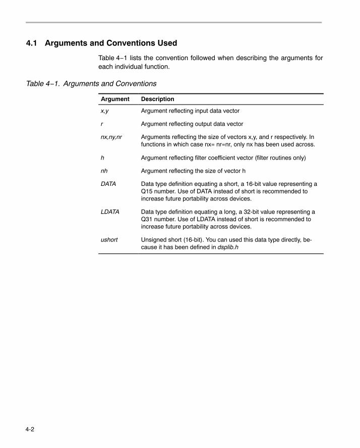
4.1 Arguments and Conventions Used
Table 4−1 lists the convention followed when describing the arguments foreach individual function.
Table 4−1. Arguments and Conventions
Argument Description
x,y Argument reflecting input data vector
r Argument reflecting output data vector
nx,ny,nr Arguments reflecting the size of vectors x,y, and r respectively. Infunctions in which case nx= nr=nr, only nx has been used across.
h Argument reflecting filter coefficient vector (filter routines only)
nh Argument reflecting the size of vector h
DATA Data type definition equating a short, a 16-bit value representing aQ15 number. Use of DATA instead of short is recommended toincrease future portability across devices.
LDATA Data type definition equating a long, a 32-bit value representing aQ31 number. Use of LDATA instead of short is recommended toincrease future portability across devices.
ushort Unsigned short (16-bit). You can used this data type directly, be-cause it has been defined in dsplib.h
4-3 Function Descriptions
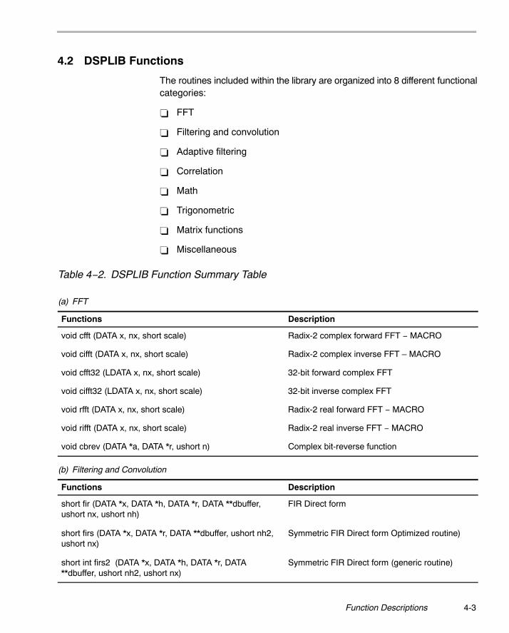
4.2 DSPLIB Functions
The routines included within the library are organized into 8 different functionalcategories:
� FFT
� Filtering and convolution
� Adaptive filtering
� Correlation
� Math
� Trigonometric
� Matrix functions
� Miscellaneous
Table 4−2. DSPLIB Function Summary Table
(a) FFT
Functions Description
void cfft (DATA x, nx, short scale) Radix-2 complex forward FFT − MACRO
void cifft (DATA x, nx, short scale) Radix-2 complex inverse FFT � MACRO
void cfft32 (LDATA x, nx, short scale) 32-bit forward complex FFT
void cifft32 (LDATA x, nx, short scale) 32-bit inverse complex FFT
void rfft (DATA x, nx, short scale) Radix-2 real forward FFT − MACRO
void rifft (DATA x, nx, short scale) Radix-2 real inverse FFT − MACRO
void cbrev (DATA *a, DATA *r, ushort n) Complex bit-reverse function
(b) Filtering and Convolution
Functions Description
short fir (DATA *x, DATA *h, DATA *r, DATA **dbuffer,ushort nx, ushort nh)
FIR Direct form
short firs (DATA *x, DATA *r, DATA **dbuffer, ushort nh2,ushort nx)
Symmetric FIR Direct form Optimized routine)
short int firs2 (DATA *x, DATA *h, DATA *r, DATA**dbuffer, ushort nh2, ushort nx)
Symmetric FIR Direct form (generic routine)
4-4
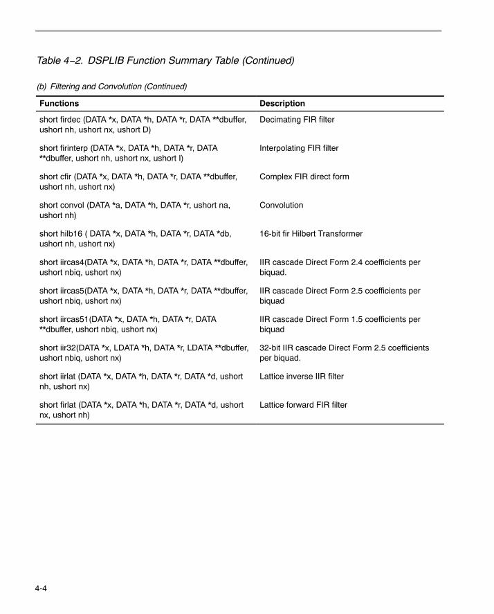
Table 4−2. DSPLIB Function Summary Table (Continued)
(b) Filtering and Convolution (Continued)
Functions Description
short firdec (DATA *x, DATA *h, DATA *r, DATA **dbuffer,ushort nh, ushort nx, ushort D)
Decimating FIR filter
short firinterp (DATA *x, DATA *h, DATA *r, DATA**dbuffer, ushort nh, ushort nx, ushort I)
Interpolating FIR filter
short cfir (DATA *x, DATA *h, DATA *r, DATA **dbuffer,ushort nh, ushort nx)
Complex FIR direct form
short convol (DATA *a, DATA *h, DATA *r, ushort na,ushort nh)
Convolution
short hilb16 ( DATA *x, DATA *h, DATA *r, DATA *db,ushort nh, ushort nx)
16-bit fir Hilbert Transformer
short iircas4(DATA *x, DATA *h, DATA *r, DATA **dbuffer,ushort nbiq, ushort nx)
IIR cascade Direct Form 2.4 coefficients perbiquad.
short iircas5(DATA *x, DATA *h, DATA *r, DATA **dbuffer,ushort nbiq, ushort nx)
IIR cascade Direct Form 2.5 coefficients perbiquad
short iircas51(DATA *x, DATA *h, DATA *r, DATA**dbuffer, ushort nbiq, ushort nx)
IIR cascade Direct Form 1.5 coefficients perbiquad
short iir32(DATA *x, LDATA *h, DATA *r, LDATA **dbuffer,ushort nbiq, ushort nx)
32-bit IIR cascade Direct Form 2.5 coefficientsper biquad.
short iirlat (DATA *x, DATA *h, DATA *r, DATA *d, ushortnh, ushort nx)
Lattice inverse IIR filter
short firlat (DATA *x, DATA *h, DATA *r, DATA *d, ushortnx, ushort nh)
Lattice forward FIR filter
4-5 Function Descriptions
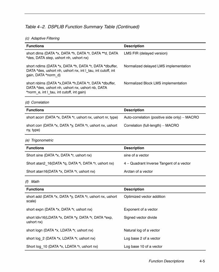
Table 4−2. DSPLIB Function Summary Table (Continued)
(c) Adaptive Filtering
Functions Description
short dlms (DATA *x, DATA *h, DATA *r, DATA **d, DATA*des, DATA step, ushort nh, ushort nx)
LMS FIR (delayed version)
short ndlms (DATA *x, DATA *h, DATA *r, DATA *dbuffer,DATA *des, ushort nh, ushort nx, int l_tau, int cutoff, intgain, DATA *norm_d)
Normalized delayed LMS implementation
short nblms (DATA *x,DATA *h,DATA *r, DATA *dbuffer,DATA *des, ushort nh, ushort nx, ushort nb, DATA*norm_e, int l_tau, int cutoff, int gain)
Normalized Block LMS implementation
(d) Correlation
Functions Description
short acorr (DATA *x, DATA *r, ushort nx, ushort nr, type) Auto-correlation (positive side only) � MACRO
short corr (DATA *x, DATA *y, DATA *r, ushort nx, ushortny, type)
Correlation (full-length) � MACRO
(e) Trigonometric
Functions Description
Short sine (DATA *x, DATA *r, ushort nx) sine of a vector
Short atan2_16(DATA *q, DATA *i, DATA *r, ushort nx) 4 − Quadrant Inverse Tangent of a vector
Short atan16(DATA *x, DATA *r, ushort nx) Arctan of a vector
(f) Math
Functions Description
short add (DATA *x, DATA *y, DATA *r, ushort nx, ushortscale)
Optimized vector addition
short expn (DATA *x, DATA *r, ushort nx) Exponent of a vector
short ldiv16(LDATA *x, DATA *y, DATA *r, DATA *exp,ushort nx)
Signed vector divide
short logn (DATA *x, LDATA *r, ushort nx) Natural log of a vector
short log_2 (DATA *x, LDATA *r, ushort nx) Log base 2 of a vector
Short log_10 (DATA *x, LDATA *r, ushort nx) Log base 10 of a vector
4-6
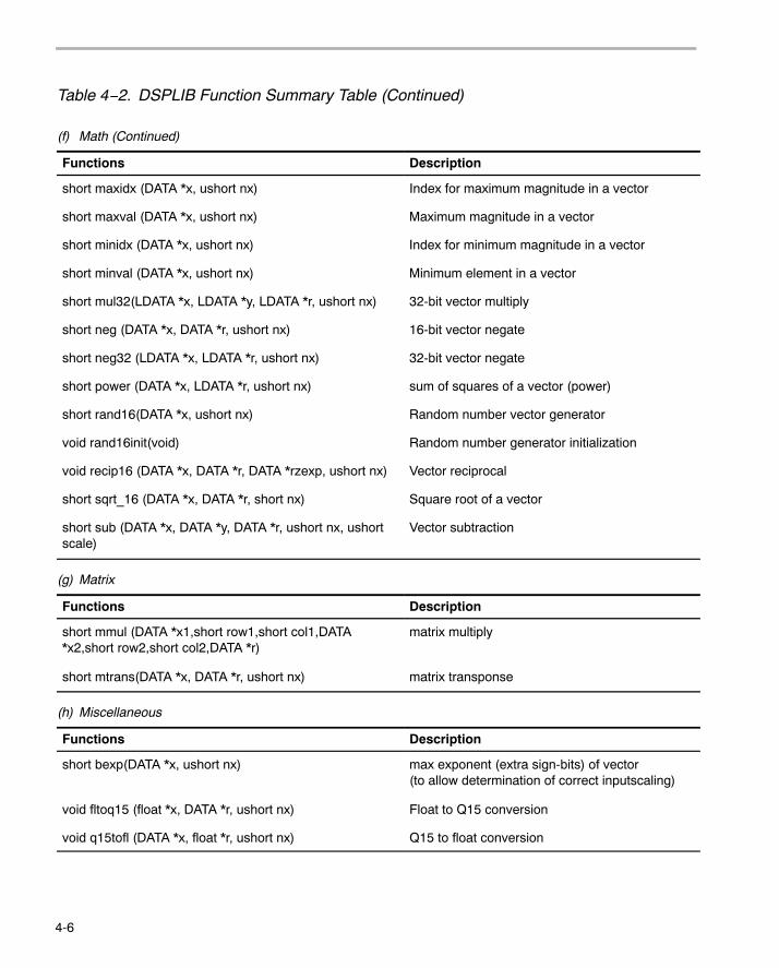
Table 4−2. DSPLIB Function Summary Table (Continued)
(f) Math (Continued)
Functions Description
short maxidx (DATA *x, ushort nx) Index for maximum magnitude in a vector
short maxval (DATA *x, ushort nx) Maximum magnitude in a vector
short minidx (DATA *x, ushort nx) Index for minimum magnitude in a vector
short minval (DATA *x, ushort nx) Minimum element in a vector
short mul32(LDATA *x, LDATA *y, LDATA *r, ushort nx) 32-bit vector multiply
short neg (DATA *x, DATA *r, ushort nx) 16-bit vector negate
short neg32 (LDATA *x, LDATA *r, ushort nx) 32-bit vector negate
short power (DATA *x, LDATA *r, ushort nx) sum of squares of a vector (power)
short rand16(DATA *x, ushort nx) Random number vector generator
void rand16init(void) Random number generator initialization
void recip16 (DATA *x, DATA *r, DATA *rzexp, ushort nx) Vector reciprocal
short sqrt_16 (DATA *x, DATA *r, short nx) Square root of a vector
short sub (DATA *x, DATA *y, DATA *r, ushort nx, ushortscale)
Vector subtraction
(g) Matrix
Functions Description
short mmul (DATA *x1,short row1,short col1,DATA*x2,short row2,short col2,DATA *r)
matrix multiply
short mtrans(DATA *x, DATA *r, ushort nx) matrix transponse
(h) Miscellaneous
Functions Description
short bexp(DATA *x, ushort nx) max exponent (extra sign-bits) of vector (to allow determination of correct inputscaling)
void fltoq15 (float *x, DATA *r, ushort nx) Float to Q15 conversion
void q15tofl (DATA *x, float *r, ushort nx) Q15 to float conversion
acorr
4-7 Function Descriptions
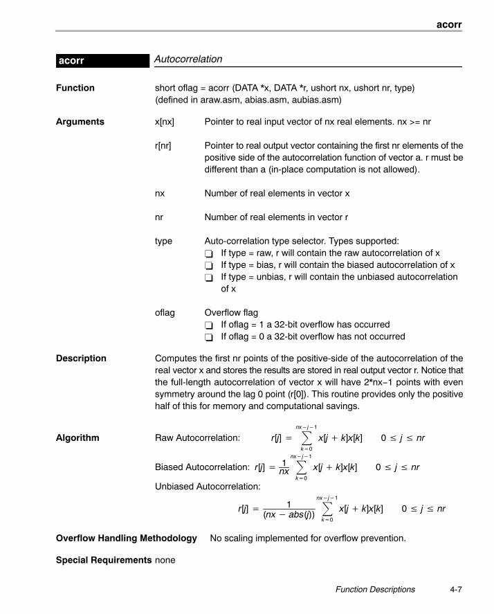
Autocorrelationacorr
Function short oflag = acorr (DATA *x, DATA *r, ushort nx, ushort nr, type)(defined in araw.asm, abias.asm, aubias.asm)
Arguments x[nx] Pointer to real input vector of nx real elements. nx >= nr
r[nr] Pointer to real output vector containing the first nr elements of thepositive side of the autocorrelation function of vector a. r must bedifferent than a (in-place computation is not allowed).
nx Number of real elements in vector x
nr Number of real elements in vector r
type Auto-correlation type selector. Types supported:� If type = raw, r will contain the raw autocorrelation of x� If type = bias, r will contain the biased autocorrelation of x� If type = unbias, r will contain the unbiased autocorrelation
of x
oflag Overflow flag� If oflag = 1 a 32-bit overflow has occurred� If oflag = 0 a 32-bit overflow has not occurred
Description Computes the first nr points of the positive-side of the autocorrelation of thereal vector x and stores the results are stored in real output vector r. Notice thatthe full-length autocorrelation of vector x will have 2*nx−1 points with evensymmetry around the lag 0 point (r[0]). This routine provides only the positivehalf of this for memory and computational savings.
Algorithm Raw Autocorrelation: r[j] � �nx�j�1
k�0
x[j � k]x[k] 0 � j � nr
Biased Autocorrelation: r[j] � 1nx �
nx�j�1
k�0
x[j � k]x[k] 0 � j � nr
Unbiased Autocorrelation:
r[j] � 1(nx � abs(j))
�nx�j�1
k�0
x[j � k]x[k] 0 � j � nr
Overflow Handling Methodology No scaling implemented for overflow prevention.
Special Requirements none
add
4-8
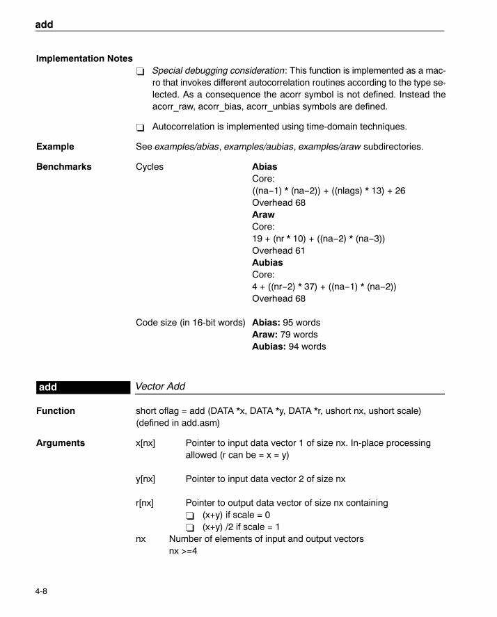
Implementation Notes� Special debugging consideration: This function is implemented as a mac-
ro that invokes different autocorrelation routines according to the type se-lected. As a consequence the acorr symbol is not defined. Instead theacorr_raw, acorr_bias, acorr_unbias symbols are defined.
� Autocorrelation is implemented using time-domain techniques.
Example See examples/abias, examples/aubias, examples/araw subdirectories.
Benchmarks Cycles AbiasCore:((na−1) * (na−2)) + ((nlags) * 13) + 26Overhead 68ArawCore:19 + (nr * 10) + ((na−2) * (na−3))Overhead 61AubiasCore:4 + ((nr−2) * 37) + ((na−1) * (na−2))Overhead 68
Code size (in 16-bit words) Abias: 95 wordsAraw: 79 wordsAubias: 94 words
Vector Addadd
Function short oflag = add (DATA *x, DATA *y, DATA *r, ushort nx, ushort scale)(defined in add.asm)
Arguments x[nx] Pointer to input data vector 1 of size nx. In-place processingallowed (r can be = x = y)
y[nx] Pointer to input data vector 2 of size nx
r[nx] Pointer to output data vector of size nx containing� (x+y) if scale = 0� (x+y) /2 if scale = 1
nx Number of elements of input and output vectorsnx >=4
atan16
4-9 Function Descriptions
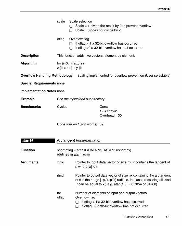
scale Scale selection� Scale = 1 divide the result by 2 to prevent overflow� Scale = 0 does not divide by 2
oflag Overflow flag� If oflag = 1 a 32-bit overflow has occurred� If oflag =0 a 32-bit overflow has not occurred
Description This function adds two vectors, element by element.
Algorithm for (i=0; i < nx; i++)z (i) = x (i) + y (i)
Overflow Handling Methodology Scaling implemented for overflow prevention (User selectable)
Special Requirements none
Implementation Notes none
Example See examples/add subdirectory
Benchmarks Cycles Core:12 + 3*nx/2Overhead 30
Code size (in 16-bit words) 39
Arctangent Implementationatan16
Function short oflag = atan16(DATA *x, DATA *r, ushort nx)(defined in atant.asm)
Arguments x[nx] Pointer to input data vector of size nx. x contains the tangent ofr, where |x| < 1.
r[nx] Pointer to output data vector of size nx containing the arctangentof x in the range [−pi/4, pi/4] radians. In-place processing allowed(r can be equal to x ) e.g. atan(1.0) = 0.7854 or 6478h)
nx Number of elements of input and output vectorsoflag Overflow flag
� If oflag = 1 a 32-bit overflow has occurred� If oflag =0 a 32-bit overflow has not occurred
atan2_16
4-10
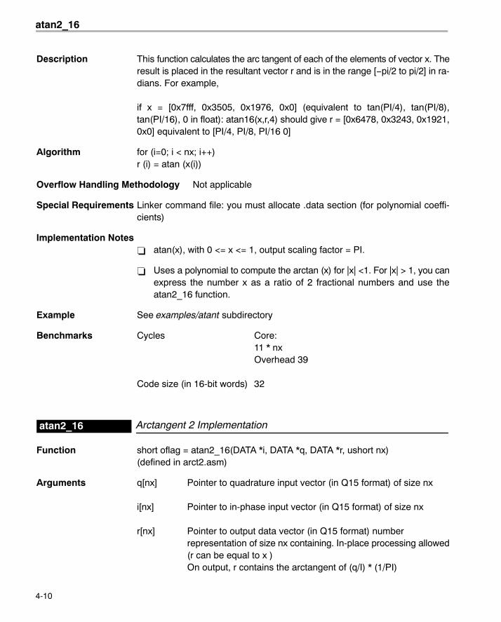
Description This function calculates the arc tangent of each of the elements of vector x. Theresult is placed in the resultant vector r and is in the range [−pi/2 to pi/2] in ra-dians. For example,
if x = [0x7fff, 0x3505, 0x1976, 0x0] (equivalent to tan(PI/4), tan(PI/8),tan(PI/16), 0 in float): atan16(x,r,4) should give r = [0x6478, 0x3243, 0x1921,0x0] equivalent to [PI/4, PI/8, PI/16 0]
Algorithm for (i=0; i < nx; i++)r (i) = atan (x(i))
Overflow Handling Methodology Not applicable
Special Requirements Linker command file: you must allocate .data section (for polynomial coeffi-cients)
Implementation Notes� atan(x), with 0 <= x <= 1, output scaling factor = PI.
� Uses a polynomial to compute the arctan (x) for |x| <1. For |x| > 1, you canexpress the number x as a ratio of 2 fractional numbers and use theatan2_16 function.
Example See examples/atant subdirectory
Benchmarks Cycles Core:11 * nxOverhead 39
Code size (in 16-bit words) 32
Arctangent 2 Implementationatan2_16
Function short oflag = atan2_16(DATA *i, DATA *q, DATA *r, ushort nx)(defined in arct2.asm)
Arguments q[nx] Pointer to quadrature input vector (in Q15 format) of size nx
i[nx] Pointer to in-phase input vector (in Q15 format) of size nx
r[nx] Pointer to output data vector (in Q15 format) numberrepresentation of size nx containing. In-place processing allowed(r can be equal to x )On output, r contains the arctangent of (q/I) * (1/PI)
bexp
4-11 Function Descriptions
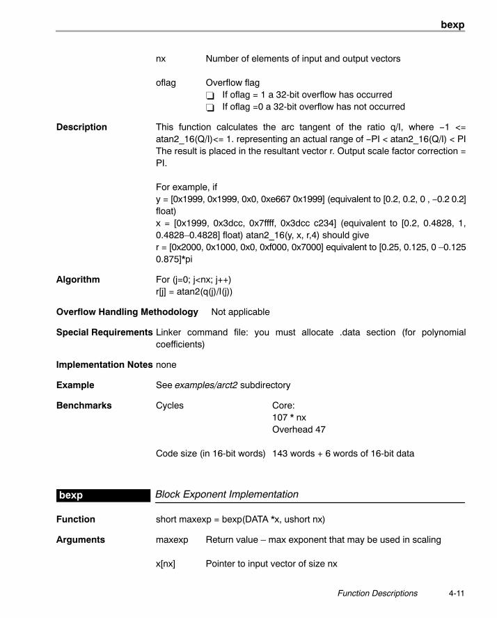
nx Number of elements of input and output vectors
oflag Overflow flag� If oflag = 1 a 32-bit overflow has occurred� If oflag =0 a 32-bit overflow has not occurred
Description This function calculates the arc tangent of the ratio q/I, where −1 <=atan2_16(Q/I)<= 1. representing an actual range of −PI < atan2_16(Q/I) < PIThe result is placed in the resultant vector r. Output scale factor correction =PI.
For example, ify = [0x1999, 0x1999, 0x0, 0xe667 0x1999] (equivalent to [0.2, 0.2, 0 , −0.2 0.2]float)x = [0x1999, 0x3dcc, 0x7ffff, 0x3dcc c234] (equivalent to [0.2, 0.4828, 1,0.4828�0.4828] float) atan2_16(y, x, r,4) should giver = [0x2000, 0x1000, 0x0, 0xf000, 0x7000] equivalent to [0.25, 0.125, 0 �0.1250.875]*pi
Algorithm For (j=0; j<nx; j++)r[j] = atan2(q(j)/I(j))
Overflow Handling Methodology Not applicable
Special Requirements Linker command file: you must allocate .data section (for polynomialcoefficients)
Implementation Notes none
Example See examples/arct2 subdirectory
Benchmarks Cycles Core:107 * nxOverhead 47
Code size (in 16-bit words) 143 words + 6 words of 16-bit data
Block Exponent Implementationbexp
Function short maxexp = bexp(DATA *x, ushort nx)
Arguments maxexp Return value � max exponent that may be used in scaling
x[nx] Pointer to input vector of size nx
cbrev
4-12
nx Number of elements of input and output vectors
oflag Overflow flag� If oflag = 1 a 32-bit overflow has occurred� If oflag =0 a 32-bit overflow has not occurred
Description Computes the exponents (number of extra sign bits) of all values in the inputvector and returns the minimum exponent. This will be useful in determiningthe maximum shift value that may be used in scaling a block of data.
Algorithm for (short j=0; j<nx; j++) temp = exp(x[j]); if (temp < maxexp) maxexp = temp;} return maxexp;
Overflow Handling Methodology Not applicable
Special Requirements none
Implementation Notes none
Example See examples/bexp subdirectory
Benchmarks Cycles Core:9 * nxOverhead 28
Code size (in 16-bit words) 29 words
Complex Bit-Reversecbrev
Function void cbrev (DATA *x, DATA *r, ushort n)(defined in cbrev.asm)
Arguments x[2*nx] Pointer to complex input vector x
r[2*nx] Pointer to complex output vector r
nx Number of complex elements of vectors x and r� To bit-reverse the input of a complex FFT, nx should be the
complex FFT size.� To bit-reverse the input of a real FFT, nx should be half the real
FFT size.
cbrev
4-13 Function Descriptions
Description This function bit-reverses the position of elements in complex vector x into out-put vector r. In-place bit-reversing is allowed. Use this function in conjunctionwith FFT routines to provide the correct format for the FFT input or output data.If you bit-reverse a linear-order array, you obtain a bit-reversed order array. Ifyou bit-reverse a bit-reversed order array, you obtain a linear-order array.
Algorithm Not applicable
Note: The C54x Overflow Handling Methodology: Not applicable
Overflow Handling Methodology Not applicable
Special Requirements Memory alignment: input data (x) must be aligned at 2*nx boundary. Thelog(nx) + 1 LSBits of address x must be zero.
Implementation Notes� x is read with bit-reversed addressing and r is written in normal linear ad-
dressing.
� In-place bit-reversing (x = r) is much more cycle consuming compared withthe off-place bit-reversing (x < > r). However this is at the expense of doub-ling the data memory requirements.
Example See examples/cfft and examples/rfft subdirectories
Benchmarks Cycles Core:2 + 3 * nx (off-place)13 * nx � 26 (in-place)Overhead 21
Code size (in 16-bit words) 50 (includes support for both in-place andoff-place bit-reverse)
Note: The C54x is capable to do an off-place bit-reverse in 2*n by using thefollowing code:
stm #N,ar0stm #INPUT, ar2 ; source address of datarpt #N*2 −1 ; looping 2*N timesmvdk *ar2+0b, #DATA
The drawback of this implementation is the hard-coding of the destination ad-dress with label #DATA. The cbrev DSPLIB implementation has chosen amore generic solution at the expense at one extra cycle (3*nx).
cfir
4-14
Complex FIR Filtercfir
Function short oflag = cfir (DATA *x, DATA *h, DATA *r, DATA **dbuffer, ushort nh,ushort nx)
Arguments x[2*nx] Pointer to compex input vector of nx complex elements (re-Im in consecutive locations)
h[2*nh] Pointer to coefficient vector of size 2*nh (nh complexelements with re-Im in consecutive locations) in normal order.For exampleif nh=3: h = b0re, b0im, b1re,b1im,b2re,b2im.Memory alignment: this is a circular buffer and must start ina k-bit boundary (that is, the k LSBs of the starting addressmust be zeros) where k = log2 (2*nh).
r[2*nx] Pointer to complex output vector of nx complex elements (re-Imin consecutive locations)In-place computation (r = x) is allowed
dbuffer[2*nh] Delay buffer� In the case of multiple-buffering schemes, this array
should be initialized to 0 for the first block only. Betweenconsecutive blocks, the delay buffer preserves theprevious r output elements needed.
� Memory alignment: this is a circular buffer and must startin a k-bit boundary (that is, the k LSBs of the startingaddress must be zeros) where k = log2 (2*nh).
nx Number of complex elements in vector x (input samples)
nh Number of complex coefficients
oflag Overflow error flag= 1 if a 32-bit data overflow has occurred in an intermediateor final result= 0 if no 32-bit data overflow has occurred in an intermediateor final result
Description Computes a real FIR filter (direct-form) using coefficient stored in vector h. Thereal data input is stored in vector x. The filter output result is stored in vectorr. This function retains the address of the delay filter memory d containing theprevious delayed values to allow consecutive processing of blocks. This func-tion can be used for both block-by-block and sample-by-sample filtering (nx=1)
cfft
4-15 Function Descriptions
Algorithm r[j] ��nh
k�0
h[k]x[j � k] 0 � j � nx
Overflow Handling Methodology No scaling implemented for overflow prevention.
Special Requirements none
Implementation Notes none
Example See examples/cfir subdirectory
Benchmarks Cycles Core:nx*(13 + 8*nh)Overhead 49
Code size (in 16-bit words) 66
Forward Complex FFTcfft
Function void cfft (DATA x, nx, short scale);(defined in cfft#.asm where #=nx)
Arguments x[2*nx] Pointer to input vector containing nx complex elements (2*nxreal elements) in bit-reversed order. On output, vector acontains the nx complex elements of the FFT(x). Complexnumbers are stored in Re-Im.
nx Number of complex elements in vector x. nx must be aconstant number (not a variable) and can take the followingvalues. nx = 8,16,32,64,128,256,512,1024
scale Flag to indicate whether or not scaling should beimplemented during computation.If (scale == 0) scale factor = 1;else scale factor = nx;end
Description Computes a Radix-2 complex DIT FFT of the nx complex elements stored invector x in bit-reversed order. The original content of vector x is destroyed inthe process. The nx complex elements of the result are stored in vector x innormal-order.
Algorithm (DFT)
y[k] � 1(scale factor)
* �nx�1
i�0
x[i] * �cos�2 * � * i * knx
� � j sin�2 * � * i * knx
��
cfft
4-16
Overflow Handling Methodology Scaling implemented for overflow prevention
Special Requirements� Special linker command file sections required: .sintab (containing the
twiddle table). For .sintab section size refer to the benchmark informationbelow.
� This function requires the inclusion of two other files during assembling(automatically included):
� macros.asm (contains all macros used for this code)
� sintab.q15 (contains twiddle table section .sintab)
� Memory alignment: Although there is no memory alignment request forthis function, you need to align input data if you use this function with func-tion cbrev (see page 4-13).
Implementation Notes� This is an FFT optimized for time. Space consumption is high due to the
use of a separate sine table in each stage. This reduce MIPS count butalso increases twiddle table data space.
� First 2 FFT stages implemented are implemented as a radix-4. Last stageis also unrolled for optimization. Twiddle factors are built-in and providedin the sintab.q15 that is automatically included during the assembly pro-cess.
� Special debugging consideration: This function is implemented as a mac-ro that invokes different FFT routines according to the size. As a conse-quence, instead of the cfft symbol being defined, multiple cfft# symbols are(where # = nx = FFT complex size).
� This routine prevents overflow by scaling by 2 at each FFT intermediatestages.
Example See examples/cfft subdirectory
cfft32
4-17 Function Descriptions
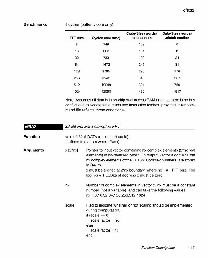
Benchmarks 8 cycles (butterfly core only)
FFT size Cycles (see note)Code-Size (words)
.text sectionData-Size (words)
.sintab section
8 149 109 0
16 322 151 11
32 733 199 34
64 1672 247 81
128 3795 295 176
256 8542 343 367
512 19049 391 750
1024 42098 439 1517
Note: Assumes all data is in on-chip dual access RAM and that there is no busconflict due to twiddle table reads and instruction fetches (provided linker com-mand file reflects those conditions).
32-Bit Forward Complex FFTcfft32
Function void cfft32 (LDATA x, nx, short scale);(defined in c#.asm where #=nx)
Arguments x [2*nx] Pointer to input vector containing nx complex elements (2*nx realelements) in bit-reversed order. On output, vector a contains thenx complex elements of the FFT(x). Complex numbers are storedin Re-Im.x must be aligned at 2*nx boundary, where nx = # = FFT size. Thelog(nx) + 1 LSBits of address x must be zero.
nx Number of complex elements in vector x. nx must be a constantnumber (not a variable) and can take the following values.nx = 8,16,32,64,128,256,512,1024
scale Flag to indicate whether or not scaling should be implementedduring computation.if (scale == 0) scale factor = nx;else scale factor = 1;end
cfft32
4-18
Description Computes a 32-bit Radix-2 complex DIT FFT of the nx complex elementsstored in vector x in bit-reversed order. The original content of vector x is de-stroyed in the process. The nx complex elements of the result are stored invector x in normal-order.
Algorithm (DFT)
y[k] � 1(scale factor)
* �nx�1
i�0
x[i] * �cos�2 * � * i * knx � � j sin�2 * � * i * k
nx ��Overflow Handling Methodology Scaling implemented for overflow prevention.
Special Requirements� Special linker command file sections required: .sintab (containing the
twiddle table). For .sintab section size refer to the benchmark informationbelow.
� This function requires the inclusion of two other files during assembling(automatically included):
� cfft_32.asm (contains all functions used for this code)
� sintab.q31 (contains twiddle table section .sintab)
Implementation Notes� This is an FFT optimized for time. Space consumption is high due to the
usage of a separate sine table in each stage. This reduce MIPS count butalso increases twiddle table data space.
� The First 2 FFT stages are implemented as a radix-4. Last stage is alsounrolled for optimization. Twiddle factors are built-in and provided in thesintab.q31 that is automatically included during the assembly process.
� Special debugging consideration: This function is implemented as a mac-ro that invokes different FFT routines according to the size. As a conse-quence, instead of the cfft32 symbol being defined, multiple cfft32_# sym-bols are (where # = nx = FFT complex size).
� This routine prevents overflow by scaling by 2 at each FFT intermediatestages.
Example See examples/cfft32 subdirectory
cifft
4-19 Function Descriptions
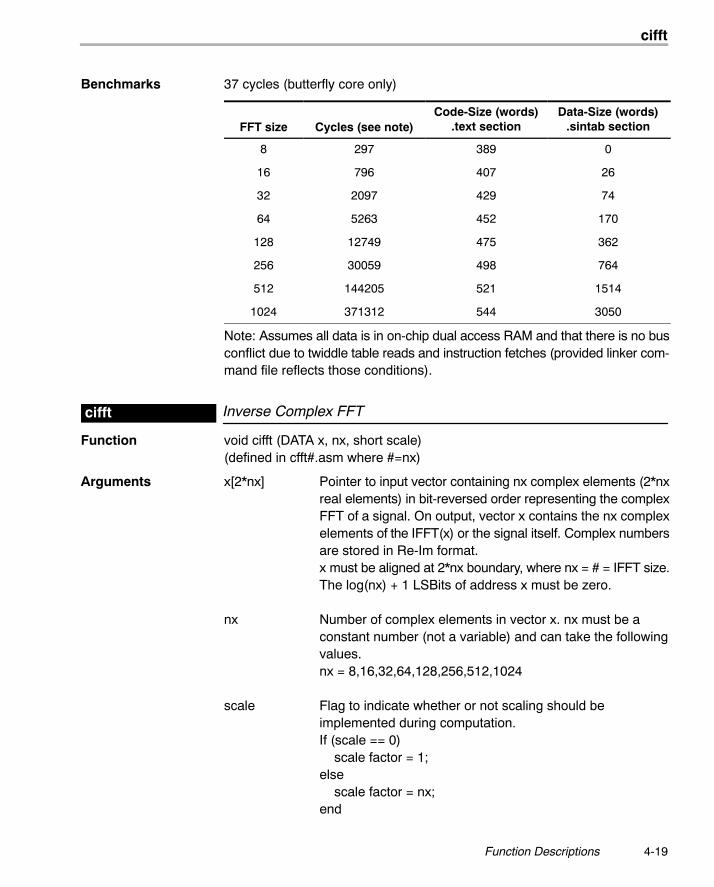
Benchmarks 37 cycles (butterfly core only)
FFT size Cycles (see note)Code-Size (words)
.text sectionData-Size (words)
.sintab section
8 297 389 0
16 796 407 26
32 2097 429 74
64 5263 452 170
128 12749 475 362
256 30059 498 764
512 144205 521 1514
1024 371312 544 3050
Note: Assumes all data is in on-chip dual access RAM and that there is no busconflict due to twiddle table reads and instruction fetches (provided linker com-mand file reflects those conditions).
Inverse Complex FFTcifft
Function void cifft (DATA x, nx, short scale)(defined in cfft#.asm where #=nx)
Arguments x[2*nx] Pointer to input vector containing nx complex elements (2*nxreal elements) in bit-reversed order representing the complexFFT of a signal. On output, vector x contains the nx complexelements of the IFFT(x) or the signal itself. Complex numbersare stored in Re-Im format.x must be aligned at 2*nx boundary, where nx = # = IFFT size.The log(nx) + 1 LSBits of address x must be zero.
nx Number of complex elements in vector x. nx must be aconstant number (not a variable) and can take the followingvalues.nx = 8,16,32,64,128,256,512,1024
scale Flag to indicate whether or not scaling should beimplemented during computation.If (scale == 0) scale factor = 1;else scale factor = nx;end
cifft
4-20
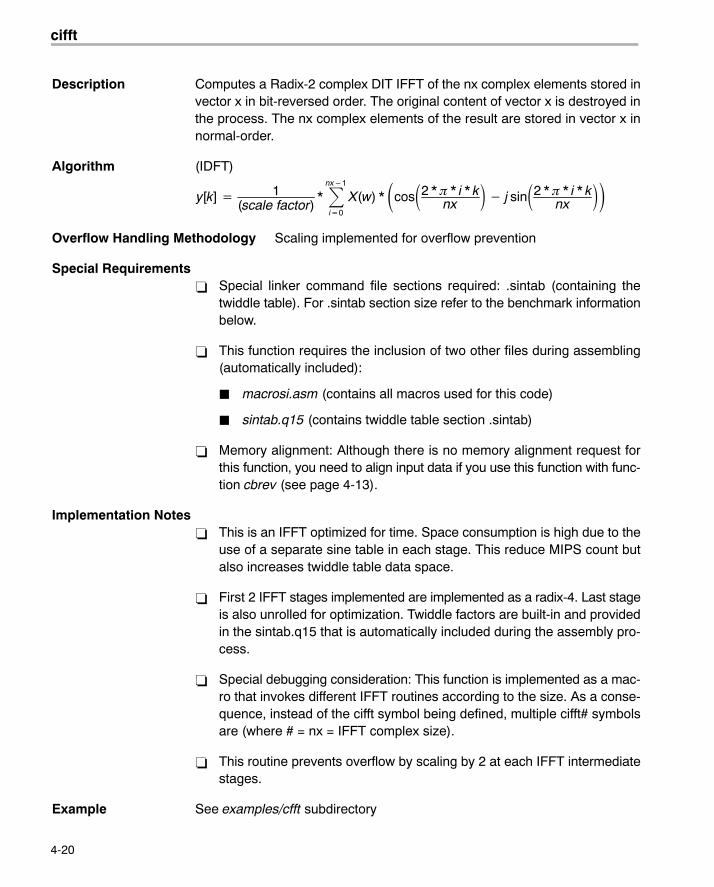
Description Computes a Radix-2 complex DIT IFFT of the nx complex elements stored invector x in bit-reversed order. The original content of vector x is destroyed inthe process. The nx complex elements of the result are stored in vector x innormal-order.
Algorithm (IDFT)
y[k] � 1(scale factor)
* �nx�1
i�0
X(w) * �cos�2 * � * i * knx
� � j sin�2 * � * i * knx
��
Overflow Handling Methodology Scaling implemented for overflow prevention
Special Requirements� Special linker command file sections required: .sintab (containing the
twiddle table). For .sintab section size refer to the benchmark informationbelow.
� This function requires the inclusion of two other files during assembling(automatically included):
� macrosi.asm (contains all macros used for this code)
� sintab.q15 (contains twiddle table section .sintab)
� Memory alignment: Although there is no memory alignment request forthis function, you need to align input data if you use this function with func-tion cbrev (see page 4-13).
Implementation Notes� This is an IFFT optimized for time. Space consumption is high due to the
use of a separate sine table in each stage. This reduce MIPS count butalso increases twiddle table data space.
� First 2 IFFT stages implemented are implemented as a radix-4. Last stageis also unrolled for optimization. Twiddle factors are built-in and providedin the sintab.q15 that is automatically included during the assembly pro-cess.
� Special debugging consideration: This function is implemented as a mac-ro that invokes different IFFT routines according to the size. As a conse-quence, instead of the cifft symbol being defined, multiple cifft# symbolsare (where # = nx = IFFT complex size).
� This routine prevents overflow by scaling by 2 at each IFFT intermediatestages.
Example See examples/cfft subdirectory
cifft32
4-21 Function Descriptions
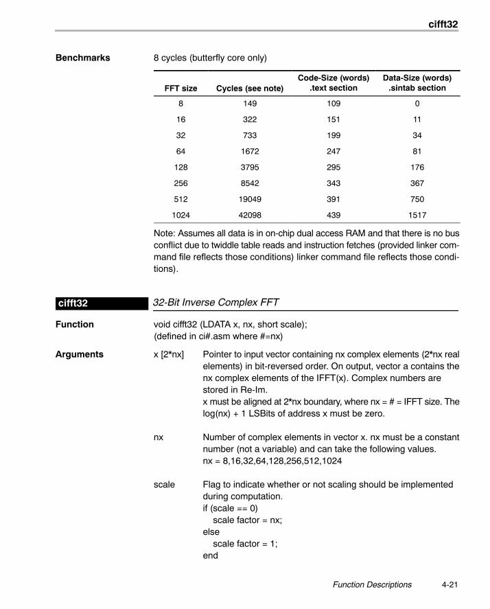
Benchmarks 8 cycles (butterfly core only)
FFT size Cycles (see note)Code-Size (words)
.text sectionData-Size (words)
.sintab section
8 149 109 0
16 322 151 11
32 733 199 34
64 1672 247 81
128 3795 295 176
256 8542 343 367
512 19049 391 750
1024 42098 439 1517
Note: Assumes all data is in on-chip dual access RAM and that there is no busconflict due to twiddle table reads and instruction fetches (provided linker com-mand file reflects those conditions) linker command file reflects those condi-tions).
32-Bit Inverse Complex FFTcifft32
Function void cifft32 (LDATA x, nx, short scale);(defined in ci#.asm where #=nx)
Arguments x [2*nx] Pointer to input vector containing nx complex elements (2*nx realelements) in bit-reversed order. On output, vector a contains thenx complex elements of the IFFT(x). Complex numbers arestored in Re-Im.x must be aligned at 2*nx boundary, where nx = # = IFFT size. Thelog(nx) + 1 LSBits of address x must be zero.
nx Number of complex elements in vector x. nx must be a constantnumber (not a variable) and can take the following values.nx = 8,16,32,64,128,256,512,1024
scale Flag to indicate whether or not scaling should be implementedduring computation.if (scale == 0) scale factor = nx;else scale factor = 1;end
cifft32
4-22
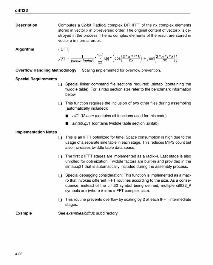
Description Computes a 32-bit Radix-2 complex DIT IFFT of the nx complex elementsstored in vector x in bit-reversed order. The original content of vector x is de-stroyed in the process. The nx complex elements of the result are stored invector x in normal-order.
Algorithm (IDFT)
y[k] � 1(scale factor)
* �nx�1
i�0
x[i] * �cos�2 * � * i * knx � � j sin�2 * � * i * k
nx ��Overflow Handling Methodology Scaling implemented for overflow prevention.
Special Requirements� Special linker command file sections required: .sintab (containing the
twiddle table). For .sintab section size refer to the benchmark informationbelow.
� This function requires the inclusion of two other files during assembling(automatically included):
� cifft_32.asm (contains all functions used for this code)
� sintab.q31 (contains twiddle table section .sintab)
Implementation Notes� This is an IFFT optimized for time. Space consumption is high due to the
usage of a separate sine table in each stage. This reduces MIPS count butalso increases twiddle table data space.
� The first 2 IFFT stages are implemented as a radix-4. Last stage is alsounrolled for optimization. Twiddle factors are built-in and provided in thesintab.q31 that is automatically included during the assembly process.
� Special debugging consideration: This function is implemented as a mac-ro that invokes different IFFT routines according to the size. As a conse-quence, instead of the cifft32 symbol being defined, multiple cifft32_#symbols are (where # = nx = FFT complex size).
� This routine prevents overflow by scaling by 2 at each IFFT intermediatestages.
Example See examples/cifft32 subdirectory
convol
4-23 Function Descriptions
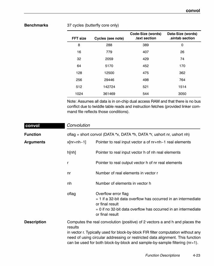
Benchmarks 37 cycles (butterfly core only)
FFT size Cycles (see note)Code-Size (words)
.text sectionData-Size (words)
.sintab section
8 288 389 0
16 779 407 26
32 2059 429 74
64 5170 452 170
128 12500 475 362
256 29446 498 764
512 142724 521 1514
1024 361469 544 3050
Note: Assumes all data is in on-chip dual access RAM and that there is no busconflict due to twiddle table reads and instruction fetches (provided linker com-mand file reflects those conditions).
Convolutionconvol
Function oflag = short convol (DATA *x, DATA *h, DATA *r, ushort nr, ushort nh)
Arguments x[nr+nh−1] Pointer to real input vector a of nr+nh−1 real elements
h[nh] Pointer to real input vector h of nh real elements
r Pointer to real output vector h of nr real elements
nr Number of real elements in vector r
nh Number of elements in vector h
oflag Overflow error flag= 1 if a 32-bit data overflow has occurred in an intermediateor final result= 0 if no 32-bit data overflow has occurred in an intermediateor final result
Description Computes the real convolution (positive) of 2 vectors a and h and places theresults in vector r. Typically used for block-by-block FIR filter computation without anyneed of using circular addressing or restricted data alignment. This functioncan be used for both block-by-block and sample-by-sample filtering (nr=1).
corr
4-24
Algorithm r[j] ��nh
k�0
h[k]x[j � k] 0 � j � nr
Overflow Handling Methodology No scaling implemented for overflow prevention
Special Requirements none
Implementation Notes none
Example See examples/convol subdirectory
Benchmarks Cycles Core:nr * (nh + 4)Overhead 35
Code size (in 16-bit words) 43
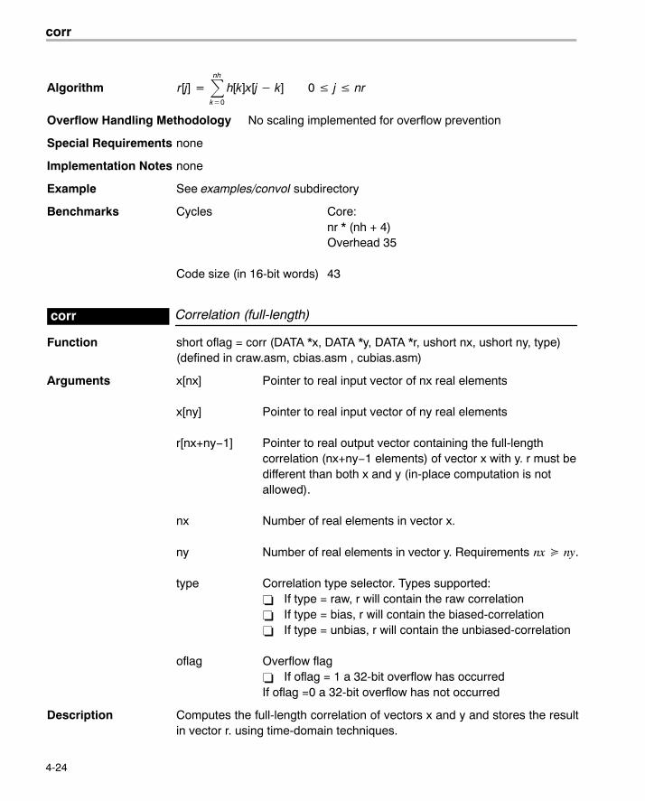
Correlation (full-length)corr
Function short oflag = corr (DATA *x, DATA *y, DATA *r, ushort nx, ushort ny, type)(defined in craw.asm, cbias.asm , cubias.asm)
Arguments x[nx] Pointer to real input vector of nx real elements
x[ny] Pointer to real input vector of ny real elements
r[nx+ny−1] Pointer to real output vector containing the full-lengthcorrelation (nx+ny−1 elements) of vector x with y. r must bedifferent than both x and y (in-place computation is notallowed).
nx Number of real elements in vector x.
ny Number of real elements in vector y. Requirements nx � ny.
type Correlation type selector. Types supported:� If type = raw, r will contain the raw correlation� If type = bias, r will contain the biased-correlation� If type = unbias, r will contain the unbiased-correlation
oflag Overflow flag� If oflag = 1 a 32-bit overflow has occurredIf oflag =0 a 32-bit overflow has not occurred
Description Computes the full-length correlation of vectors x and y and stores the resultin vector r. using time-domain techniques.
corr
4-25 Function Descriptions
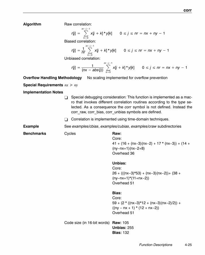
Algorithm Raw correlation:
r[j] � �nr�j�1
k�0
x[j � k] * y[k] 0 � j � nr � nx � ny � 1
Biased correlation:
r[j] � 1nr �
nr�j�1
k�0
x[j � k] * y[k] 0 � j � nr � nx � ny � 1
Unbiased correlation:
r[j] � 1(nx � abs(j))
�nr�j�1
k�0
x[j � k] * y[k] 0 � j � nr � nx � ny � 1
Overflow Handling Methodology No scaling implemented for overflow prevention
Special Requirements nx � ny
Implementation Notes� Special debugging consideration: This function is implemented as a mac-
ro that invokes different correlation routines according to the type se-lected. As a consequence the corr symbol is not defined. Instead thecorr_raw, corr_bias, corr_unbias symbols are defined.
� Correlation is implemented using time-domain techniques.
Example See examples/cbias, examples/cubias, examples/craw subdirectories
Benchmarks Cycles Raw:Core:
41 + (16 + (nx−3)(nx−2) + 17 * (nx−3)) + (14 +(ny−nx+1)(nx−2+8)Overhead 36
Unbias:Core:26 + (((nx−3)*53) + (nx−3)(nx−2))+ (38 +(ny−nx+1)*(11+nx−2))Overhead 51
Bias:Core:59 + (2 * ((nx−3)*12 + (nx−3)(nx−2)/2)) +((ny − nx + 1) * (12 + nx−2))Overhead 51
Code size (in 16-bit words) Raw: 105Unbias: 255Bias: 132
dlms
4-26
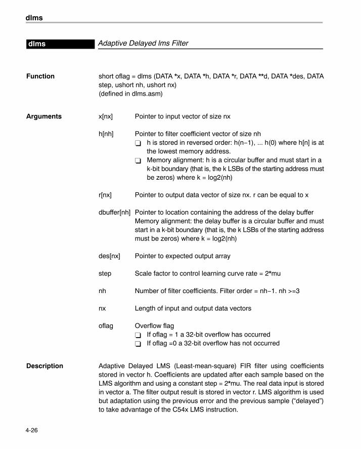
Adaptive Delayed lms Filterdlms
Function short oflag = dlms (DATA *x, DATA *h, DATA *r, DATA **d, DATA *des, DATAstep, ushort nh, ushort nx)(defined in dlms.asm)
Arguments x[nx] Pointer to input vector of size nx
h[nh] Pointer to filter coefficient vector of size nh� h is stored in reversed order: h(n−1), ... h(0) where h[n] is at
the lowest memory address.� Memory alignment: h is a circular buffer and must start in a
k-bit boundary (that is, the k LSBs of the starting address mustbe zeros) where k = log2(nh)
r[nx] Pointer to output data vector of size nx. r can be equal to x
dbuffer[nh] Pointer to location containing the address of the delay bufferMemory alignment: the delay buffer is a circular buffer and muststart in a k-bit boundary (that is, the k LSBs of the starting addressmust be zeros) where k = log2(nh)
des[nx] Pointer to expected output array
step Scale factor to control learning curve rate = 2*mu
nh Number of filter coefficients. Filter order = nh−1. nh >=3
nx Length of input and output data vectors
oflag Overflow flag� If oflag = 1 a 32-bit overflow has occurred� If oflag =0 a 32-bit overflow has not occurred
Description Adaptive Delayed LMS (Least-mean-square) FIR filter using coefficientsstored in vector h. Coefficients are updated after each sample based on theLMS algorithm and using a constant step = 2*mu. The real data input is storedin vector a. The filter output result is stored in vector r. LMS algorithm is usedbut adaptation using the previous error and the previous sample (�delayed�)to take advantage of the C54x LMS instruction.
expn
4-27 Function Descriptions
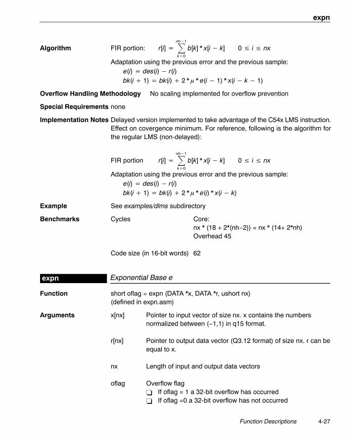
Algorithm FIR portion: r[i] � �nh�1
k�0
b[k] * x[i � k] 0 � i � nx
Adaptation using the previous error and the previous sample:e(i) � des(i) � r(i)bk(i � 1) � bk(i) � 2 * � * e(i � 1) * x(i � k � 1)
Overflow Handling Methodology No scaling implemented for overflow prevention
Special Requirements none
Implementation Notes Delayed version implemented to take advantage of the C54x LMS instruction.Effect on covergence minimum. For reference, following is the algorithm forthe regular LMS (non-delayed):
FIR portion r[i] � �nh�1
k�0
b[k] * x[i � k] 0 � i � nx
Adaptation using the previous error and the previous sample:e(i) � des(i) � r(i)bk(i � 1) � bk(i) � 2 * � * e(i) * x(i � k)
Example See examples/dlms subdirectory
Benchmarks Cycles Core:nx * (18 + 2*(nh−2)) = nx * (14+ 2*nh)Overhead 45
Code size (in 16-bit words) 62
Exponential Base eexpn
Function short oflag = expn (DATA *x, DATA *r, ushort nx)(defined in expn.asm)
Arguments x[nx] Pointer to input vector of size nx. x contains the numbersnormalized between (−1,1) in q15 format.
r[nx] Pointer to output data vector (Q3.12 format) of size nx. r can beequal to x.
nx Length of input and output data vectors
oflag Overflow flag� If oflag = 1 a 32-bit overflow has occurred� If oflag =0 a 32-bit overflow has not occurred
fir
4-28
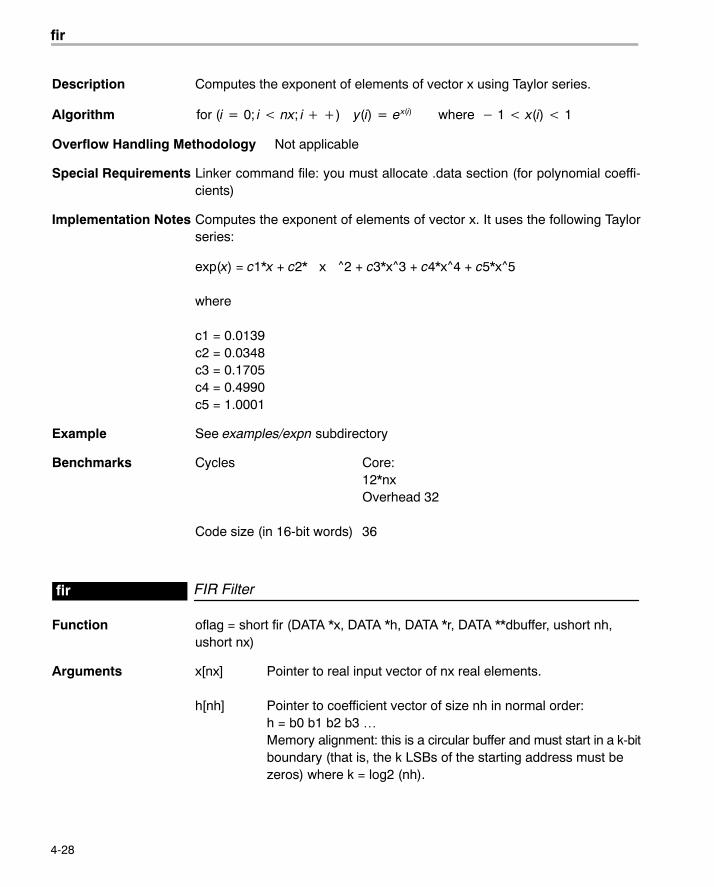
Description Computes the exponent of elements of vector x using Taylor series.
Algorithm for (i � 0; i nx; i ��) y(i) � ex(i) where � 1 x(i) 1
Overflow Handling Methodology Not applicable
Special Requirements Linker command file: you must allocate .data section (for polynomial coeffi-cients)
Implementation Notes Computes the exponent of elements of vector x. It uses the following Taylorseries:
exp(x) = c1*x + c2* x ^2 + c3*x^3 + c4*x^4 + c5*x^5
where
c1 = 0.0139c2 = 0.0348c3 = 0.1705c4 = 0.4990c5 = 1.0001
Example See examples/expn subdirectory
Benchmarks Cycles Core:12*nxOverhead 32
Code size (in 16-bit words) 36
FIR Filterfir
Function oflag = short fir (DATA *x, DATA *h, DATA *r, DATA **dbuffer, ushort nh,ushort nx)
Arguments x[nx] Pointer to real input vector of nx real elements.
h[nh] Pointer to coefficient vector of size nh in normal order: h = b0 b1 b2 b3 …Memory alignment: this is a circular buffer and must start in a k-bitboundary (that is, the k LSBs of the starting address must bezeros) where k = log2 (nh).
fir
4-29 Function Descriptions
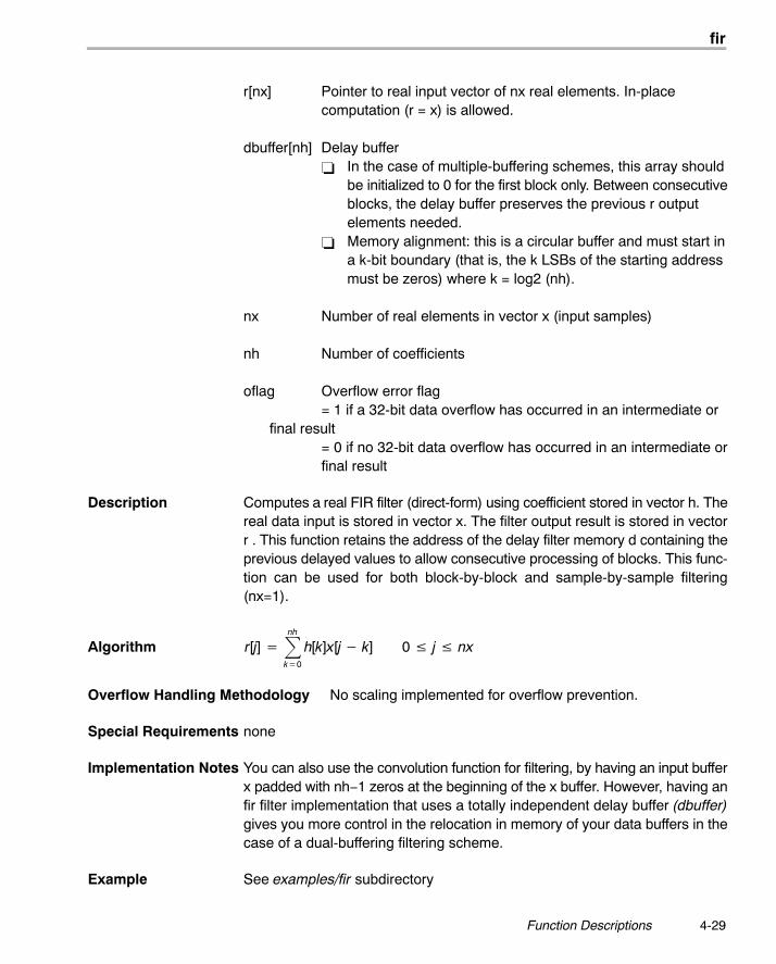
r[nx] Pointer to real input vector of nx real elements. In-placecomputation (r = x) is allowed.
dbuffer[nh] Delay buffer� In the case of multiple-buffering schemes, this array should
be initialized to 0 for the first block only. Between consecutiveblocks, the delay buffer preserves the previous r outputelements needed.
� Memory alignment: this is a circular buffer and must start ina k-bit boundary (that is, the k LSBs of the starting addressmust be zeros) where k = log2 (nh).
nx Number of real elements in vector x (input samples)
nh Number of coefficients
oflag Overflow error flag = 1 if a 32-bit data overflow has occurred in an intermediate or
final result= 0 if no 32-bit data overflow has occurred in an intermediate orfinal result
Description Computes a real FIR filter (direct-form) using coefficient stored in vector h. Thereal data input is stored in vector x. The filter output result is stored in vectorr . This function retains the address of the delay filter memory d containing theprevious delayed values to allow consecutive processing of blocks. This func-tion can be used for both block-by-block and sample-by-sample filtering(nx=1).
Algorithm r[j] ��nh
k�0
h[k]x[j � k] 0 � j � nx
Overflow Handling Methodology No scaling implemented for overflow prevention.
Special Requirements none
Implementation Notes You can also use the convolution function for filtering, by having an input bufferx padded with nh−1 zeros at the beginning of the x buffer. However, having anfir filter implementation that uses a totally independent delay buffer (dbuffer)gives you more control in the relocation in memory of your data buffers in thecase of a dual-buffering filtering scheme.
Example See examples/fir subdirectory
firdec
4-30
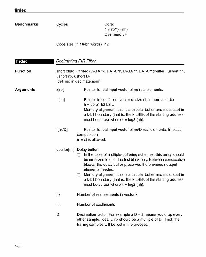
Benchmarks Cycles Core:4 + nx*(4+nh)Overhead 34
Code size (in 16-bit words) 42
Decimating FIR Filterfirdec
Function short oflag = firdec (DATA *x, DATA *h, DATA *r, DATA **dbuffer , ushort nh,ushort nx, ushort D)(defined in decimate.asm)
Arguments x[nx] Pointer to real input vector of nx real elements.
h[nh] Pointer to coefficient vector of size nh in normal order:h = b0 b1 b2 b3 …Memory alignment: this is a circular buffer and must start ina k-bit boundary (that is, the k LSBs of the starting addressmust be zeros) where k = log2 (nh).
r[nx/D] Pointer to real input vector of nx/D real elements. In-placecomputation (r = x) is allowed.
dbuffer[nh] Delay buffer� In the case of multiple-buffering schemes, this array should
be initialized to 0 for the first block only. Between consecutiveblocks, the delay buffer preserves the previous r outputelements needed.
� Memory alignment: this is a circular buffer and must start ina k-bit boundary (that is, the k LSBs of the starting addressmust be zeros) where k = log2 (nh).
nx Number of real elements in vector x
nh Number of coefficients
D Decimation factor. For example a D = 2 means you drop everyother sample. Ideally, nx should be a multiple of D. If not, thetrailing samples will be lost in the process.
firinterp
4-31 Function Descriptions
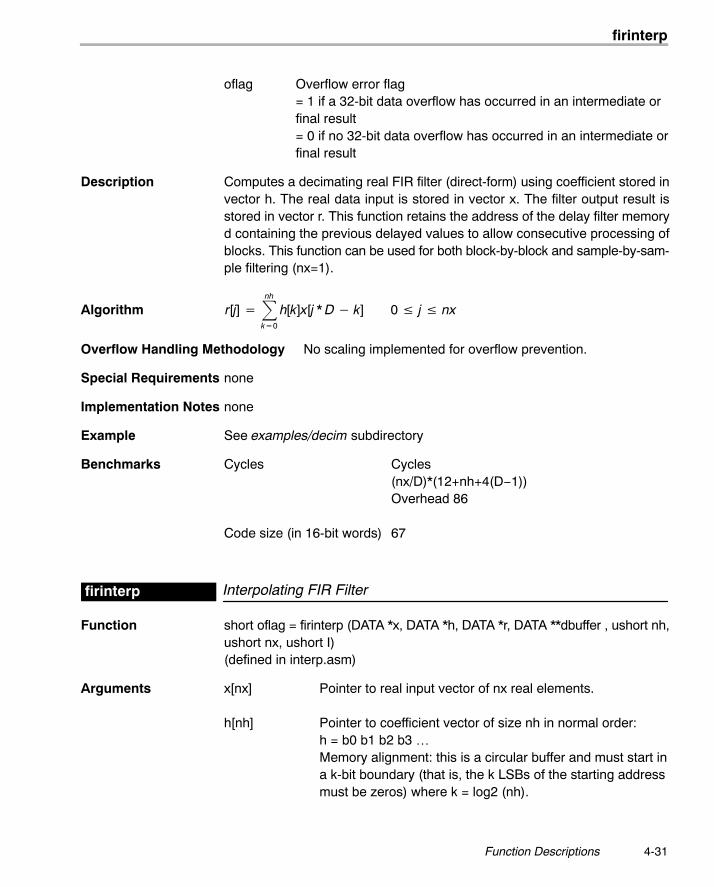
oflag Overflow error flag = 1 if a 32-bit data overflow has occurred in an intermediate orfinal result= 0 if no 32-bit data overflow has occurred in an intermediate orfinal result
Description Computes a decimating real FIR filter (direct-form) using coefficient stored invector h. The real data input is stored in vector x. The filter output result isstored in vector r. This function retains the address of the delay filter memoryd containing the previous delayed values to allow consecutive processing ofblocks. This function can be used for both block-by-block and sample-by-sam-ple filtering (nx=1).
Algorithm r[j] ��nh
k�0
h[k]x[j * D � k] 0 � j � nx
Overflow Handling Methodology No scaling implemented for overflow prevention.
Special Requirements none
Implementation Notes none
Example See examples/decim subdirectory
Benchmarks Cycles Cycles(nx/D)*(12+nh+4(D−1))Overhead 86
Code size (in 16-bit words) 67
Interpolating FIR Filterfirinterp
Function short oflag = firinterp (DATA *x, DATA *h, DATA *r, DATA **dbuffer , ushort nh,ushort nx, ushort I)(defined in interp.asm)
Arguments x[nx] Pointer to real input vector of nx real elements.
h[nh] Pointer to coefficient vector of size nh in normal order:h = b0 b1 b2 b3 …Memory alignment: this is a circular buffer and must start ina k-bit boundary (that is, the k LSBs of the starting addressmust be zeros) where k = log2 (nh).
firinterp
4-32
r[nx*I] Pointer to real output vector of nx real elements.
dbuffer[nh] Delay buffer� In the case of multiple-buffering schemes, this array
should be initialized to 0 for the first block only. Betweenconsecutive blocks, the delay buffer preserves theprevious r output elements needed.
� Memory alignment: this is a circular buffer and must startin a k-bit boundary (that is, the k LSBs of the startingaddress must be zeros) where k = log2 (nh).
nx Number of real elements in vector x and r
nh Number of coefficients
I Interpolation factor. For example an I = 2 means you will addone sample result for every sample.
oflag Overflow error flag= 1 if a 32-bit data overflow has occurred in an intermediateor final result= 0 if no 32-bit data overflow has occurred in an intermediateor final result
Description Computes an interpolating real FIR filter (direct-form) using coefficient storedin vector h. The real data input is stored in vector x. The filter output result isstored in vector r. This function retains the address of the delay filter memoryd containing the previous delayed values to allow consecutive processing ofblocks. This function can be used for both block-by-block and sample-by-sam-ple filtering (nx=1).
Algorithm r[t] ��nh
k�0
h[k]x tI � k
� 0 � j � nr
Overflow Handling Methodology No scaling implemented for overflow prevention.
Special Requirements none
Implementation Notes none
Example See examples/decimate subdirectory
Benchmarks Cycles Core:nx*(6+(I−1)*(17+(nh/I)))Overhead 88
Code size (in 16-bit words) 74
firs
4-33 Function Descriptions
Symmetric FIR Filterfirs
Function short oflag = int firs (DATA *x, DATA *r, DATA **dbuffer, ushort nh2, ushort nx)
Arguments x[nx] Pointer to real input vector of nx real elements.
r[nx] Pointer to real input vector of nx real elements. In-placecomputation (r = x) is allowed.
dbuffer[2*nh2] Delay buffer of size nh = 2*nh2� In the case of multiple-buffering schemes, this array
should be initialized to 0 for the first block only. Betweenconsecutive blocks, the delay buffer preserves theprevious r output elements needed.
� Memory alignment: this is a circular buffer and must startin a k-bit boundary (that is, the k LSBs of the startingaddress must be zeros) where k = log2 (2*nh2).
nx Number of real elements in vector a (input samples)
nh2 Half the number of coefficients of the filter (due to symmetrythere is no need to provide the other half)
oflag Overflow error flag= 1 if a 32-bit data overflow has occurred in an intermediateor final result= 0 if no 32-bit data overflow has occurred in an intermediateor final result
Description Computes a real FIR filter (direct-form) using the nh2 coefficients stored in pro-gram location pointed by TI_FIRS_COEFFS global label. The filter is assumedto have a symmetric impulse response, with the first half of the filter coefficientsstored in locations pointed by TI_FIRS_COEFFS. The real data input is storedin vector x. The filter output result is stored in vector r. This function retains theaddress of the delay filter memory d containing the previous delayed valuesto allow consecutive processing of blocks. This function can be used for bothblock-by-block and sample-by-sample filtering (nx=1).
Algorithm r[j] ��nh
k�0
h[k]x[t � k] 0 � j � nx
whereh is symmetric (for example h = h0 h1 h2 h2 h1 h0 where nh2 = 3. Only h0, h1,h2 are stored in program memory pointed by the TI_LIB_COEFFS global la-bel)
firs2
4-34
Overflow Handling Methodology No scaling implemented for overflow prevention.
Special Requirements Filter coefficients must be provided in program space with a global label calledTI_LIB_COEFFS pointing to the start of the coefficient table.
Implementation Notes Although this routine is faster than the generic symmetric filter routine (firs2)included in DSPLIB, it is restrictive in that the address for the coefficients ishard-coded to the global label TI_LIB_COEFFS in program memory. Thiscould be a problem in the event you want to use multiple filtering routines withdifferent coefficient values. If that is the case, use the firs2 routine.
Example See examples/firs subdirectory
Benchmarks Cycles Core:nx * (16+nh)Overhead 35
Code size (in 16-bit words) 56
Symmetric FIR Filter (generic)firs2
Function short oflag = int firs2 (DATA *x, DATA *h, DATA *r, DATA *dbptr, ushort nh2,ushort nx)
Arguments x[nx] Pointer to real input vector of nx real elements.
r[nx] Pointer to real input vector of nx real elements. In-placecomputation (r = x) is allowed.
h[nh2] Pointer to vector containing 1st half the filter coefficients. Itassumes that the filter has a symmetric impulse response(filter coefficients). The total number of filter coefficients is2*nh2. For example if:The filter coefficients are b0 b1 b1 b0then nh2 = 2 and h = { b0, b1 }
dbptr[2] Delay buffer pointer array contains two pointers to the delaybuffer: dbuffer[2*nh2]. The delay buffer dbuffer has size 2*nh2.� In the case of multiple-buffering schemes, the delay
buffer should be initialized to 0 for the first block only.Between consecutive blocks, the delay buffer preservesthe previous r output elements needed.
firs2
4-35 Function Descriptions
� Memory alignment: the delay buffer is a circular buffer and must start in a k-bit boundary (that is, the k LSBs ofthe starting address must be zeros) where k = log2 (2*nh2).
nx Number of real elements in vector x (input samples)
nh2 Half the number of coefficients of the filter (due to symmetrythere is no need to provide the other half)
oflag Overflow error flag= 1 if a 32-bit data overflow has occurred in an intermediateor final result= 0 if no 32-bit data overflow has occurred in an intermediateor final result
Description Computes a real FIR filter (direct-form) using the nh2 coefficients stored inarray h (data memory). The filter is assumed to have a symmetric impulse re-sponse, so array h stores only the first half of the filter coefficients. The realdata input is stored in vector x. The filter output result is stored in vector r. Thisfunction retains the address of the delay filter memory d containing the pre-vious delayed values to allow consecutive processing of blocks. This functioncan be used for both block-by-block and sample-by-sample filtering (nx=1).
Algorithm r[j] ��nh
k�0
h[k]x[t � k] o � j � nx
where h is symmetric (for example h = h0 h1 h2 h2 h1 h0 where nh2 = 3. Onlyh0, h1, h2 are stored in data memory)
Overflow Handling Methodology No scaling implemented for overflow prevention.
Special Requirements none
Implementation Notes Although this routine is slower than the symmetric filter routine (firs) includedin DSPLIB, it does not impose any restrictions in the location of the coefficientvector or in the use of multiple filtering routines in the same executable.
Example See examples/firs2 subdirectory
Benchmarks Cycles Core:nx*(15 + 2*nh2)Overhead 43
Code size (in 16-bit words) 58
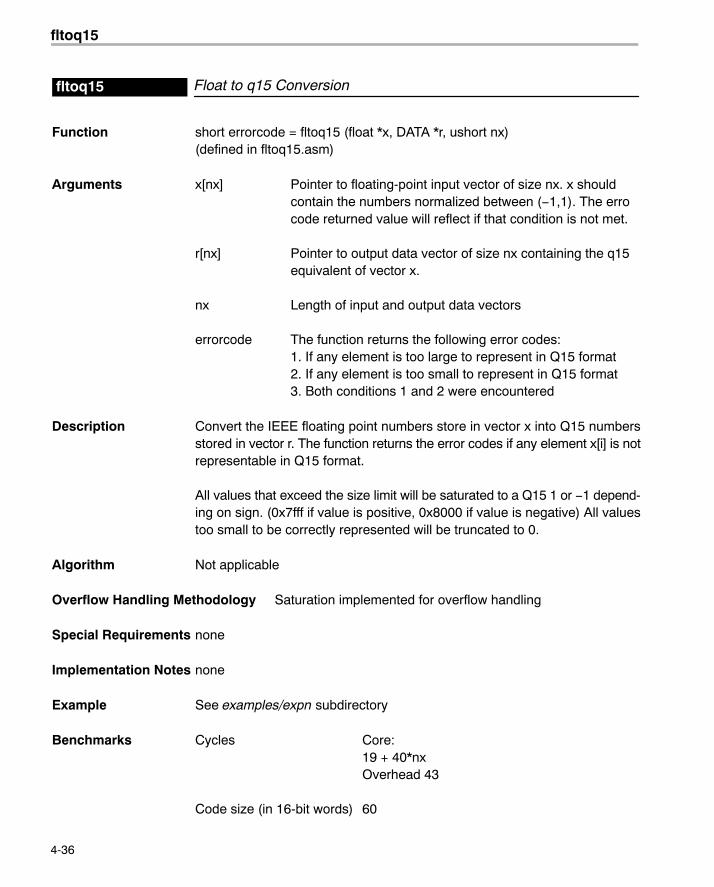
fltoq15
4-36
Float to q15 Conversionfltoq15
Function short errorcode = fltoq15 (float *x, DATA *r, ushort nx)(defined in fltoq15.asm)
Arguments x[nx] Pointer to floating-point input vector of size nx. x shouldcontain the numbers normalized between (−1,1). The errocode returned value will reflect if that condition is not met.
r[nx] Pointer to output data vector of size nx containing the q15equivalent of vector x.
nx Length of input and output data vectors
errorcode The function returns the following error codes:1. If any element is too large to represent in Q15 format2. If any element is too small to represent in Q15 format3. Both conditions 1 and 2 were encountered
Description Convert the IEEE floating point numbers store in vector x into Q15 numbersstored in vector r. The function returns the error codes if any element x[i] is notrepresentable in Q15 format.
All values that exceed the size limit will be saturated to a Q15 1 or −1 depend-ing on sign. (0x7fff if value is positive, 0x8000 if value is negative) All valuestoo small to be correctly represented will be truncated to 0.
Algorithm Not applicable
Overflow Handling Methodology Saturation implemented for overflow handling
Special Requirements none
Implementation Notes none
Example See examples/expn subdirectory
Benchmarks Cycles Core:19 + 40*nxOverhead 43
Code size (in 16-bit words) 60
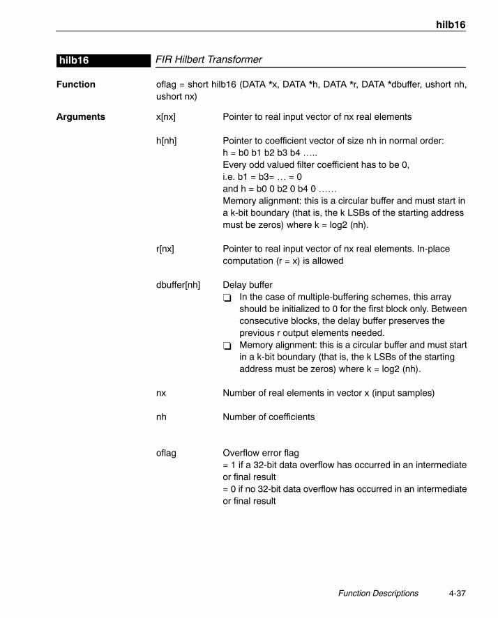
hilb16
4-37 Function Descriptions
FIR Hilbert Transformerhilb16
Function oflag = short hilb16 (DATA *x, DATA *h, DATA *r, DATA *dbuffer, ushort nh,ushort nx)
Arguments x[nx] Pointer to real input vector of nx real elements
h[nh] Pointer to coefficient vector of size nh in normal order:h = b0 b1 b2 b3 b4 …..Every odd valued filter coefficient has to be 0,i.e. b1 = b3= … = 0and h = b0 0 b2 0 b4 0 ……Memory alignment: this is a circular buffer and must start ina k-bit boundary (that is, the k LSBs of the starting addressmust be zeros) where k = log2 (nh).
r[nx] Pointer to real input vector of nx real elements. In-placecomputation (r = x) is allowed
dbuffer[nh] Delay buffer� In the case of multiple-buffering schemes, this array
should be initialized to 0 for the first block only. Betweenconsecutive blocks, the delay buffer preserves theprevious r output elements needed.
� Memory alignment: this is a circular buffer and must startin a k-bit boundary (that is, the k LSBs of the startingaddress must be zeros) where k = log2 (nh).
nx Number of real elements in vector x (input samples)
nh Number of coefficients
oflag Overflow error flag = 1 if a 32-bit data overflow has occurred in an intermediateor final result= 0 if no 32-bit data overflow has occurred in an intermediateor final result
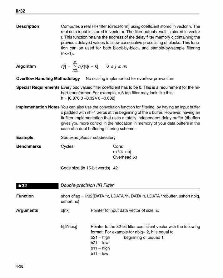
iir32
4-38
Description Computes a real FIR filter (direct-form) using coefficient stored in vector h. Thereal data input is stored in vector x. The filter output result is stored in vectorr. This function retains the address of the delay filter memory d containing theprevious delayed values to allow consecutive processing of blocks. This func-tion can be used for both block-by-block and sample-by-sample filtering(nx=1).
Algorithm r[j] ��nh
k�0
h[k]x[j � k] 0 � j � nx
Overflow Handling Methodology No scaling implemented for overflow prevention.
Special Requirements Every odd valued filter coefficient has to be 0. This is a requirement for the hil-bert transformer. For example, a 5 tap filter may look like this:h = [0.876 0 �0.324 0 �0.002]
Implementation Notes You can also use the convolution function for filtering, by having an input bufferx padded with nh−1 zeros at the beginning of the x buffer. However, having anfir filter implementation that uses a totally independent delay buffer (dbuffer)gives you more control in the relocation in memory of your data buffers in thecase of a dual-buffering filtering scheme.
Example See examples/fir subdirectory
Benchmarks Cycles Core:nx*(4+nh)Overhead 53
Code size (in 16-bit words) 42
Double-precision IIR Filteriir32
Function short oflag = iir32(DATA *x, LDATA *h, DATA *r, LDATA **dbuffer, ushort nbiq,ushort nx)
Arguments x[nx] Pointer to input data vector of size nx
h[5*nbiq] Pointer to the 32-bit filter coefficient vector with the followingformat. For example for nbiq= 2, h is equal to:b21 � high beginning of biquad 1b21 � lowb11 � highb11 � low
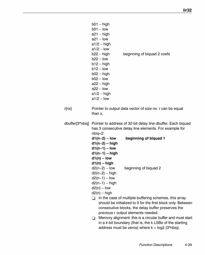
iir32
4-39 Function Descriptions
b01 � highb01 � lowa21 � higha21 � lowa1/2 � higha1/2 � lowb22 � high beginning of biquad 2 coefsb22 � lowb12 � highb12 � lowb02 � highb02 � lowa22 � higha22 � lowa1/2 � higha1/2 � low
r[nx] Pointer to output data vector of size nx. r can be equalthan x.
dbuffer[3*nbiq] Pointer to address of 32-bit delay line dbuffer. Each biquadhas 3 consecutive delay line elements. For example fornbiq=2:d1(n−2) − low beginning of biquad 1d1(n−2) � highd1(n−1) � lowd1(n−1) � highd1(n) � lowd1(n) � highd2(n−2) − low beginning of biquad 2d2(n−2) − highd2(n−1) � lowd2(n−1) � highd2(n) � lowd2(n) � high� In the case of multiple-buffering schemes, this array
should be initialized to 0 for the first block only. Betweenconsecutive blocks, the delay buffer preserves theprevious r output elements needed.
� Memory alignment: this is a circular buffer and must startin a k-bit boundary (that is, the k LSBs of the startingaddress must be zeros) where k = log2 (3*nbiq).
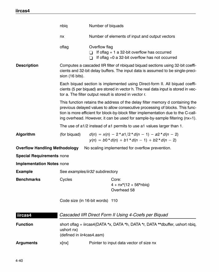
iircas4
4-40
nbiq Number of biquads
nx Number of elements of input and output vectors
oflag Overflow flag� If oflag = 1 a 32-bit overflow has occurred� If oflag =0 a 32-bit overflow has not occurred
Description Computes a cascaded IIR filter of nbiquad biquad sections using 32-bit coeffi-cients and 32-bit delay buffers. The input data is assumed to be single-preci-sion (16 bits).
Each biquad section is implemented using Direct-form II. All biquad coeffi-cients (5 per biquad) are stored in vector h. The real data input is stored in vec-tor a. The filter output result is stored in vector r.
This function retains the address of the delay filter memory d containing theprevious delayed values to allow consecutive processing of blocks. This func-tion is more efficient for block-by-block filter implementation due to the C-call-ing overhead. However, it can be used for sample-by-sample filtering (nx=1).
The use of a1/2 instead of a1 permits to use a1 values larger than 1.
Algorithm (for biquad) d(n) � x(n) � 2 * a1�2 * d(n � 1) � a2 * d(n � 2)y(n) � b0 * d(n) � b1 * d(n � 1) � b2 * d(n � 2)
Overflow Handling Methodology No scaling implemented for overflow prevention.
Special Requirements none
Implementation Notes none
Example See examples/iir32 subdirectory
Benchmarks Cycles Core:4 + nx*(12 + 56*nbiq)Overhead 58
Code size (in 16-bit words) 110
Cascaded IIR Direct Form II Using 4-Coefs per Biquadiircas4
Function short oflag = iircas4(DATA *x, DATA *h, DATA *r, DATA **dbuffer, ushort nbiq,ushort nx)(defined in iir4cas4.asm)
Arguments x[nx] Pointer to input data vector of size nx
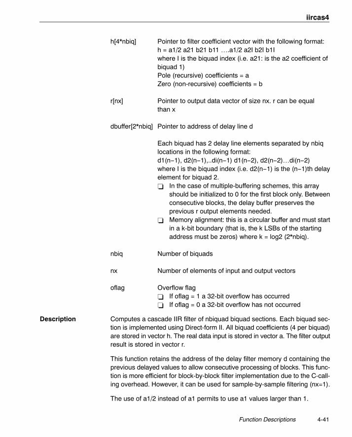
iircas4
4-41 Function Descriptions
h[4*nbiq] Pointer to filter coefficient vector with the following format:h = a1/2 a21 b21 b11 ….a1/2 a2I b2I b1Iwhere I is the biquad index (i.e. a21: is the a2 coefficient ofbiquad 1)Pole (recursive) coefficients = aZero (non-recursive) coefficients = b
r[nx] Pointer to output data vector of size nx. r can be equalthan x
dbuffer[2*nbiq] Pointer to address of delay line d
Each biquad has 2 delay line elements separated by nbiqlocations in the following format:d1(n−1), d2(n−1),..di(n−1) d1(n−2), d2(n−2)…di(n−2)where I is the biquad index (i.e. d2(n−1) is the (n−1)th delayelement for biquad 2.� In the case of multiple-buffering schemes, this array
should be initialized to 0 for the first block only. Betweenconsecutive blocks, the delay buffer preserves theprevious r output elements needed.
� Memory alignment: this is a circular buffer and must startin a k-bit boundary (that is, the k LSBs of the startingaddress must be zeros) where k = log2 (2*nbiq).
nbiq Number of biquads
nx Number of elements of input and output vectors
oflag Overflow flag� If oflag = 1 a 32-bit overflow has occurred� If oflag = 0 a 32-bit overflow has not occurred
Description Computes a cascade IIR filter of nbiquad biquad sections. Each biquad sec-tion is implemented using Direct-form II. All biquad coefficients (4 per biquad)are stored in vector h. The real data input is stored in vector a. The filter outputresult is stored in vector r.
This function retains the address of the delay filter memory d containing theprevious delayed values to allow consecutive processing of blocks. This func-tion is more efficient for block-by-block filter implementation due to the C-call-ing overhead. However, it can be used for sample-by-sample filtering (nx=1).
The use of a1/2 instead of a1 permits to use a1 values larger than 1.
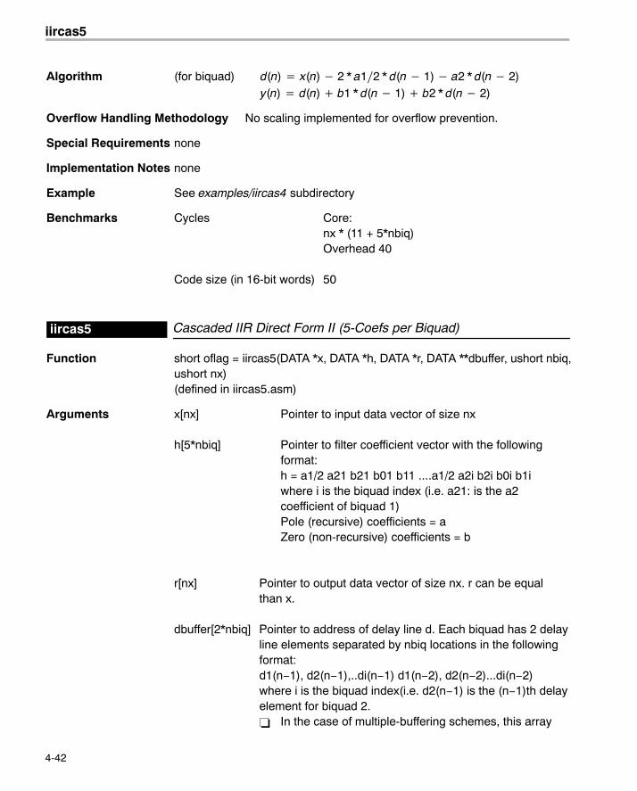
iircas5
4-42
Algorithm (for biquad) d(n) � x(n) � 2 * a1�2 * d(n � 1) � a2 * d(n � 2)y(n) � d(n) � b1 * d(n � 1) � b2 * d(n � 2)
Overflow Handling Methodology No scaling implemented for overflow prevention.
Special Requirements none
Implementation Notes none
Example See examples/iircas4 subdirectory
Benchmarks Cycles Core:nx * (11 + 5*nbiq)Overhead 40
Code size (in 16-bit words) 50
Cascaded IIR Direct Form II (5-Coefs per Biquad)iircas5
Function short oflag = iircas5(DATA *x, DATA *h, DATA *r, DATA **dbuffer, ushort nbiq,ushort nx)(defined in iircas5.asm)
Arguments x[nx] Pointer to input data vector of size nx
h[5*nbiq] Pointer to filter coefficient vector with the followingformat:h = a1/2 a21 b21 b01 b11 ....a1/2 a2i b2i b0i b1iwhere i is the biquad index (i.e. a21: is the a2coefficient of biquad 1)Pole (recursive) coefficients = aZero (non-recursive) coefficients = b
r[nx] Pointer to output data vector of size nx. r can be equalthan x.
dbuffer[2*nbiq] Pointer to address of delay line d. Each biquad has 2 delayline elements separated by nbiq locations in the followingformat:d1(n−1), d2(n−1),..di(n−1) d1(n−2), d2(n−2)...di(n−2) where i is the biquad index(i.e. d2(n−1) is the (n−1)th delayelement for biquad 2.� In the case of multiple-buffering schemes, this array
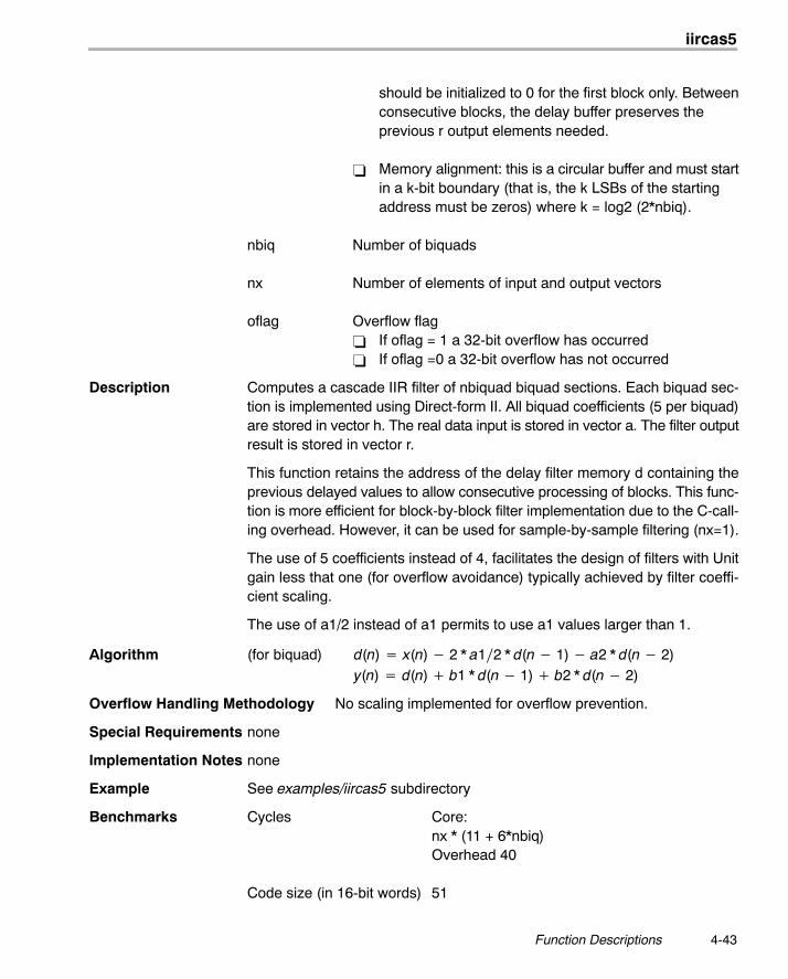
iircas5
4-43 Function Descriptions
should be initialized to 0 for the first block only. Betweenconsecutive blocks, the delay buffer preserves theprevious r output elements needed.
� Memory alignment: this is a circular buffer and must startin a k-bit boundary (that is, the k LSBs of the startingaddress must be zeros) where k = log2 (2*nbiq).
nbiq Number of biquads
nx Number of elements of input and output vectors
oflag Overflow flag� If oflag = 1 a 32-bit overflow has occurred� If oflag =0 a 32-bit overflow has not occurred
Description Computes a cascade IIR filter of nbiquad biquad sections. Each biquad sec-tion is implemented using Direct-form II. All biquad coefficients (5 per biquad)are stored in vector h. The real data input is stored in vector a. The filter outputresult is stored in vector r.
This function retains the address of the delay filter memory d containing theprevious delayed values to allow consecutive processing of blocks. This func-tion is more efficient for block-by-block filter implementation due to the C-call-ing overhead. However, it can be used for sample-by-sample filtering (nx=1).
The use of 5 coefficients instead of 4, facilitates the design of filters with Unitgain less that one (for overflow avoidance) typically achieved by filter coeffi-cient scaling.
The use of a1/2 instead of a1 permits to use a1 values larger than 1.
Algorithm (for biquad) d(n) � x(n) � 2 * a1�2 * d(n � 1) � a2 * d(n � 2)y(n) � d(n) � b1 * d(n � 1) � b2 * d(n � 2)
Overflow Handling Methodology No scaling implemented for overflow prevention.
Special Requirements none
Implementation Notes none
Example See examples/iircas5 subdirectory
Benchmarks Cycles Core:nx * (11 + 6*nbiq)Overhead 40
Code size (in 16-bit words) 51
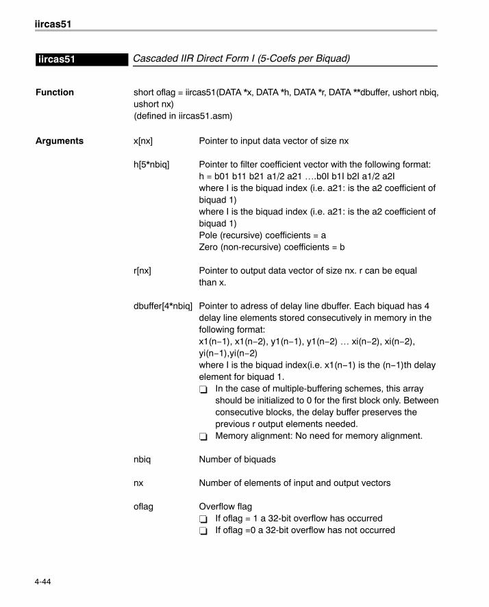
iircas51
4-44
Cascaded IIR Direct Form I (5-Coefs per Biquad)iircas51
Function short oflag = iircas51(DATA *x, DATA *h, DATA *r, DATA **dbuffer, ushort nbiq,ushort nx)(defined in iircas51.asm)
Arguments x[nx] Pointer to input data vector of size nx
h[5*nbiq] Pointer to filter coefficient vector with the following format:h = b01 b11 b21 a1/2 a21 ….b0I b1I b2I a1/2 a2Iwhere I is the biquad index (i.e. a21: is the a2 coefficient ofbiquad 1)where I is the biquad index (i.e. a21: is the a2 coefficient of biquad 1)Pole (recursive) coefficients = aZero (non-recursive) coefficients = b
r[nx] Pointer to output data vector of size nx. r can be equalthan x.
dbuffer[4*nbiq] Pointer to adress of delay line dbuffer. Each biquad has 4delay line elements stored consecutively in memory in thefollowing format:x1(n−1), x1(n−2), y1(n−1), y1(n−2) … xi(n−2), xi(n−2),yi(n−1),yi(n−2)where I is the biquad index(i.e. x1(n−1) is the (n−1)th delayelement for biquad 1.� In the case of multiple-buffering schemes, this array
should be initialized to 0 for the first block only. Betweenconsecutive blocks, the delay buffer preserves theprevious r output elements needed.
� Memory alignment: No need for memory alignment.
nbiq Number of biquads
nx Number of elements of input and output vectors
oflag Overflow flag� If oflag = 1 a 32-bit overflow has occurred� If oflag =0 a 32-bit overflow has not occurred
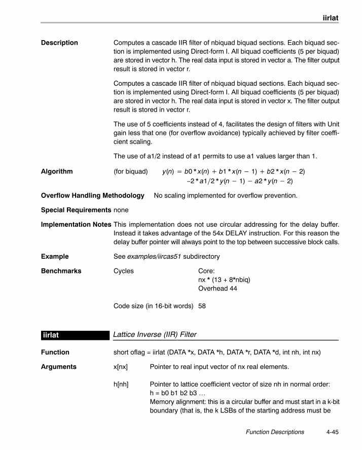
iirlat
4-45 Function Descriptions
Description Computes a cascade IIR filter of nbiquad biquad sections. Each biquad sec-tion is implemented using Direct-form I. All biquad coefficients (5 per biquad)are stored in vector h. The real data input is stored in vector a. The filter outputresult is stored in vector r.
Computes a cascade IIR filter of nbiquad biquad sections. Each biquad sec-tion is implemented using Direct-form I. All biquad coefficients (5 per biquad)are stored in vector h. The real data input is stored in vector x. The filter outputresult is stored in vector r.
The use of 5 coefficients instead of 4, facilitates the design of filters with Unitgain less that one (for overflow avoidance) typically achieved by filter coeffi-cient scaling.
The use of a1/2 instead of a1 permits to use a1 values larger than 1.
Algorithm (for biquad) y(n) � b0 * x(n) � b1 * x(n � 1) � b2 * x(n � 2)−2 * a1�2 * y(n � 1) � a2 * y(n � 2)
Overflow Handling Methodology No scaling implemented for overflow prevention.
Special Requirements none
Implementation Notes This implementation does not use circular addressing for the delay buffer.Instead it takes advantage of the 54x DELAY instruction. For this reason thedelay buffer pointer will always point to the top between successive block calls.
Example See examples/iircas51 subdirectory
Benchmarks Cycles Core:nx * (13 + 8*nbiq)Overhead 44
Code size (in 16-bit words) 58
Lattice Inverse (IIR) Filteriirlat
Function short oflag = iirlat (DATA *x, DATA *h, DATA *r, DATA *d, int nh, int nx)
Arguments x[nx] Pointer to real input vector of nx real elements.
h[nh] Pointer to lattice coefficient vector of size nh in normal order: h = b0 b1 b2 b3 …Memory alignment: this is a circular buffer and must start in a k-bitboundary (that is, the k LSBs of the starting address must be
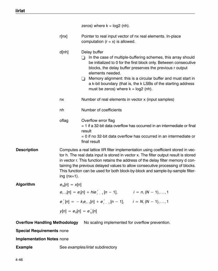
iirlat
4-46
zeros) where k = log2 (nh).
r[nx] Pointer to real input vector of nx real elements. In-placecomputation (r = x) is allowed.
d[nh] Delay buffer� In the case of multiple-buffering schemes, this array should
be initialized to 0 for the first block only. Between consecutiveblocks, the delay buffer preserves the previous r outputelements needed.
� Memory alignment: this is a circular buffer and must start ina k-bit boundary (that is, the k LSBs of the starting addressmust be zeros) where k = log2 (nh).
nx Number of real elements in vector x (input samples)
nh Number of coefficients
oflag Overflow error flag= 1 if a 32-bit data overflow has occurred in an intermediate or finalresult= 0 if no 32-bit data overflow has occurred in an intermediate orfinal result
Description Computes a real lattice IIR filter implementation using coefficient stored in vec-tor h. The real data input is stored in vector x. The filter output result is storedin vector r. This function retains the address of the delay filter memory d con-taining the previous delayed values to allow consecutive processing of blocks.This function can be used for both block-by-block and sample-by-sample filter-ing (nx=1).
Algorithm eN[n] � x[n]
ei�1[n] � ei[n] � hie i � 1 [n � 1], i � n, (N � 1), . . . , 1
e i [n] � � kiei�1[n] � e
i � 1 [n � 1], i � N, (N � 1), . . . , 1
y[n] � e0[n] � e 0 [n]
Overflow Handling Methodology No scaling implemented for overflow prevention.
Special Requirements none
Implementation Notes none
Example See examples/iirlat subdirectory
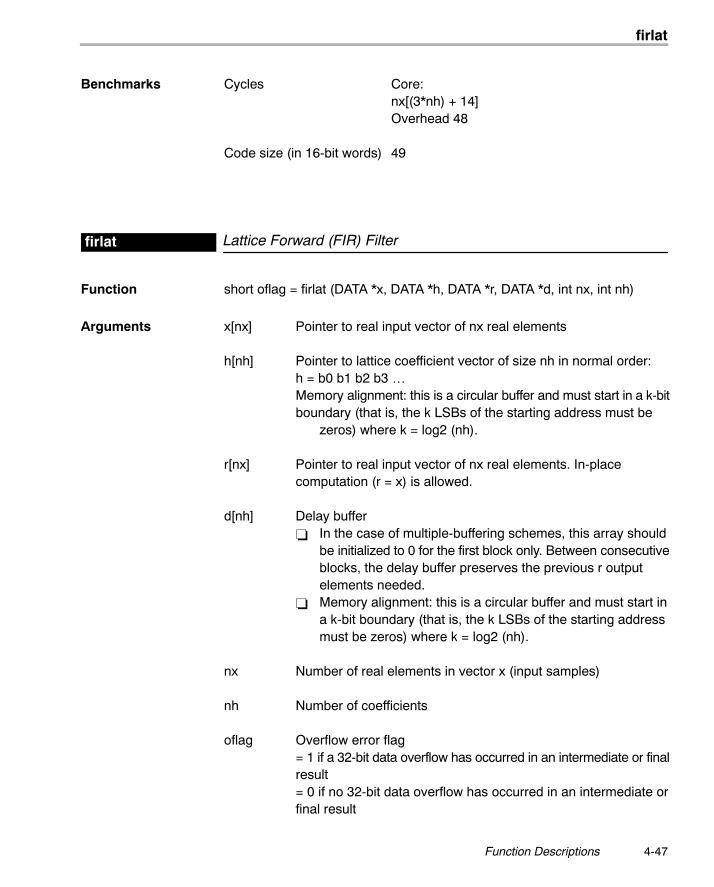
firlat
4-47 Function Descriptions
Benchmarks Cycles Core:nx[(3*nh) + 14]Overhead 48
Code size (in 16-bit words) 49
Lattice Forward (FIR) Filterfirlat
Function short oflag = firlat (DATA *x, DATA *h, DATA *r, DATA *d, int nx, int nh)
Arguments x[nx] Pointer to real input vector of nx real elements
h[nh] Pointer to lattice coefficient vector of size nh in normal order:h = b0 b1 b2 b3 …Memory alignment: this is a circular buffer and must start in a k-bitboundary (that is, the k LSBs of the starting address must be
zeros) where k = log2 (nh).
r[nx] Pointer to real input vector of nx real elements. In-placecomputation (r = x) is allowed.
d[nh] Delay buffer� In the case of multiple-buffering schemes, this array should
be initialized to 0 for the first block only. Between consecutiveblocks, the delay buffer preserves the previous r outputelements needed.
� Memory alignment: this is a circular buffer and must start ina k-bit boundary (that is, the k LSBs of the starting addressmust be zeros) where k = log2 (nh).
nx Number of real elements in vector x (input samples)
nh Number of coefficients
oflag Overflow error flag = 1 if a 32-bit data overflow has occurred in an intermediate or finalresult= 0 if no 32-bit data overflow has occurred in an intermediate orfinal result
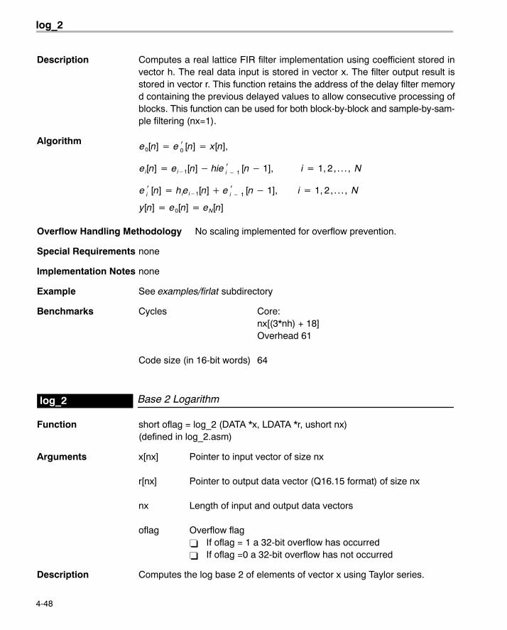
log_2
4-48
Description Computes a real lattice FIR filter implementation using coefficient stored invector h. The real data input is stored in vector x. The filter output result isstored in vector r. This function retains the address of the delay filter memoryd containing the previous delayed values to allow consecutive processing ofblocks. This function can be used for both block-by-block and sample-by-sam-ple filtering (nx=1).
Algorithm e0[n] � e 0 [n] � x[n],
ei[n] � ei�1[n] � hie i � 1 [n � 1], i � 1, 2, . . . , N
e i [n] � hiei�1[n] � e
i � 1 [n � 1], i � 1, 2, . . . , N
y[n] � e0[n] � eN[n]
Overflow Handling Methodology No scaling implemented for overflow prevention.
Special Requirements none
Implementation Notes none
Example See examples/firlat subdirectory
Benchmarks Cycles Core:nx[(3*nh) + 18]Overhead 61
Code size (in 16-bit words) 64
Base 2 Logarithmlog_2
Function short oflag = log_2 (DATA *x, LDATA *r, ushort nx)(defined in log_2.asm)
Arguments x[nx] Pointer to input vector of size nx
r[nx] Pointer to output data vector (Q16.15 format) of size nx
nx Length of input and output data vectors
oflag Overflow flag� If oflag = 1 a 32-bit overflow has occurred� If oflag =0 a 32-bit overflow has not occurred
Description Computes the log base 2 of elements of vector x using Taylor series.
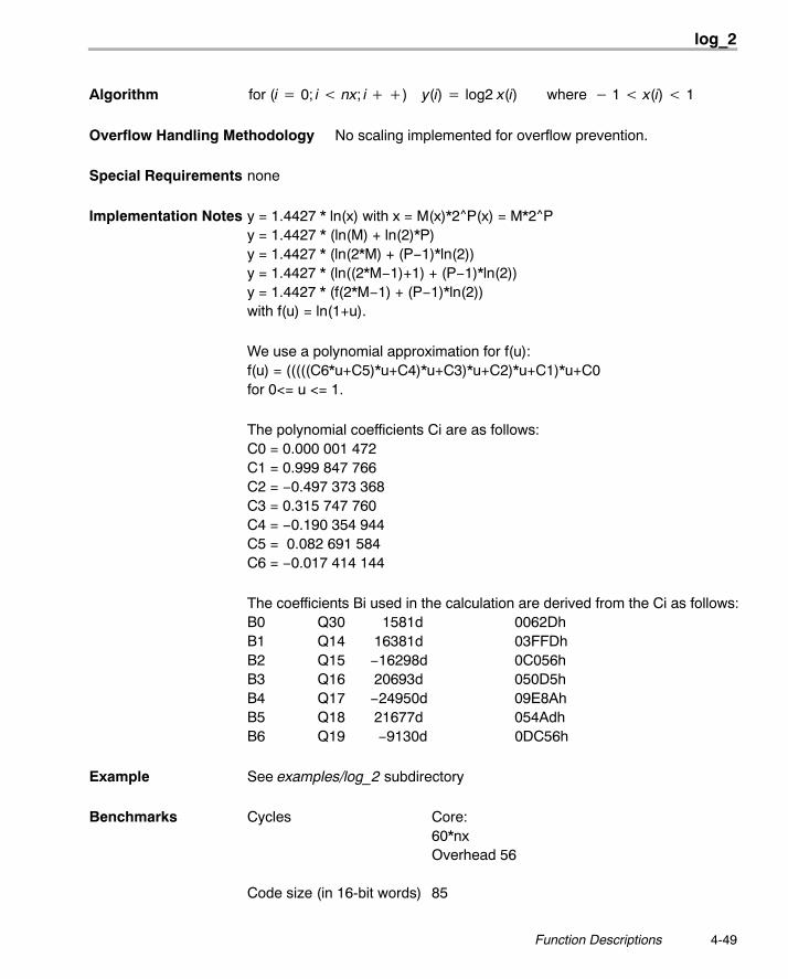
log_2
4-49 Function Descriptions
Algorithm for (i � 0; i nx; i ��) y(i) � log2 x(i) where � 1 x(i) 1
Overflow Handling Methodology No scaling implemented for overflow prevention.
Special Requirements none
Implementation Notes y = 1.4427 * ln(x) with x = M(x)*2^P(x) = M*2^Py = 1.4427 * (ln(M) + ln(2)*P)y = 1.4427 * (ln(2*M) + (P−1)*ln(2))y = 1.4427 * (ln((2*M−1)+1) + (P−1)*ln(2))y = 1.4427 * (f(2*M−1) + (P−1)*ln(2))with f(u) = ln(1+u).
We use a polynomial approximation for f(u):f(u) = (((((C6*u+C5)*u+C4)*u+C3)*u+C2)*u+C1)*u+C0for 0<= u <= 1.
The polynomial coefficients Ci are as follows:C0 = 0.000 001 472C1 = 0.999 847 766C2 = −0.497 373 368C3 = 0.315 747 760C4 = −0.190 354 944 C5 = 0.082 691 584C6 = −0.017 414 144
The coefficients Bi used in the calculation are derived from the Ci as follows:B0 Q30 1581d 0062DhB1 Q14 16381d 03FFDhB2 Q15 −16298d 0C056hB3 Q16 20693d 050D5hB4 Q17 −24950d 09E8AhB5 Q18 21677d 054AdhB6 Q19 −9130d 0DC56h
Example See examples/log_2 subdirectory
Benchmarks Cycles Core:60*nxOverhead 56
Code size (in 16-bit words) 85
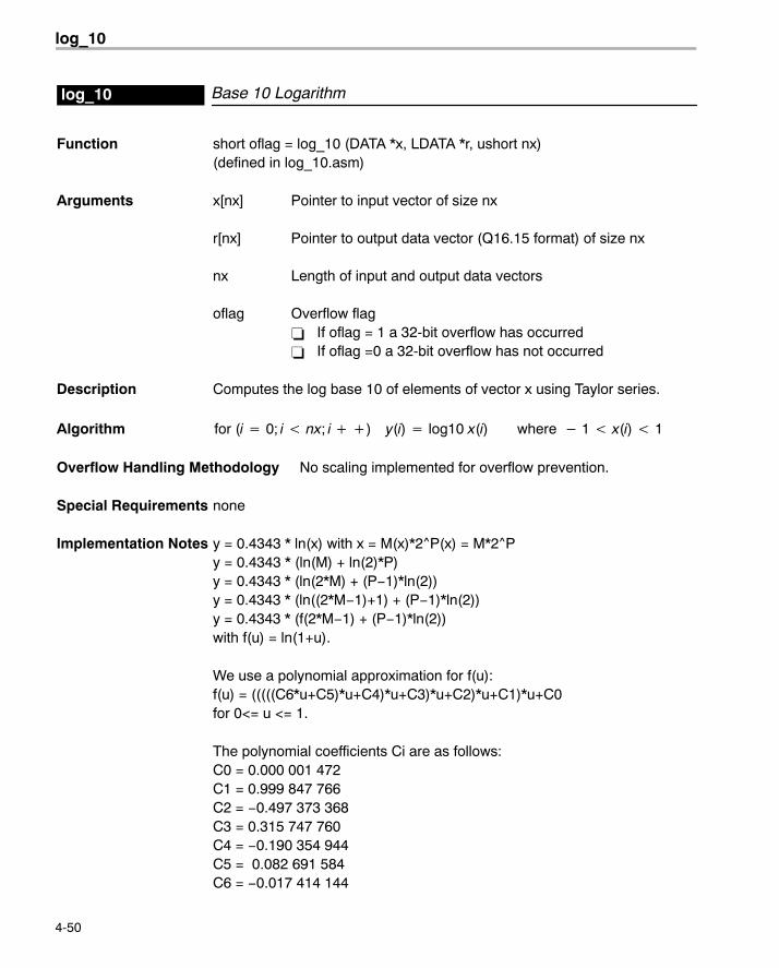
log_10
4-50
Base 10 Logarithmlog_10
Function short oflag = log_10 (DATA *x, LDATA *r, ushort nx)(defined in log_10.asm)
Arguments x[nx] Pointer to input vector of size nx
r[nx] Pointer to output data vector (Q16.15 format) of size nx
nx Length of input and output data vectors
oflag Overflow flag� If oflag = 1 a 32-bit overflow has occurred� If oflag =0 a 32-bit overflow has not occurred
Description Computes the log base 10 of elements of vector x using Taylor series.
Algorithm for (i � 0; i nx; i ��) y(i) � log10 x(i) where � 1 x(i) 1
Overflow Handling Methodology No scaling implemented for overflow prevention.
Special Requirements none
Implementation Notes y = 0.4343 * ln(x) with x = M(x)*2^P(x) = M*2^Py = 0.4343 * (ln(M) + ln(2)*P)y = 0.4343 * (ln(2*M) + (P−1)*ln(2))y = 0.4343 * (ln((2*M−1)+1) + (P−1)*ln(2))y = 0.4343 * (f(2*M−1) + (P−1)*ln(2))with f(u) = ln(1+u).
We use a polynomial approximation for f(u):f(u) = (((((C6*u+C5)*u+C4)*u+C3)*u+C2)*u+C1)*u+C0for 0<= u <= 1.
The polynomial coefficients Ci are as follows:C0 = 0.000 001 472C1 = 0.999 847 766C2 = −0.497 373 368C3 = 0.315 747 760C4 = −0.190 354 944C5 = 0.082 691 584C6 = −0.017 414 144
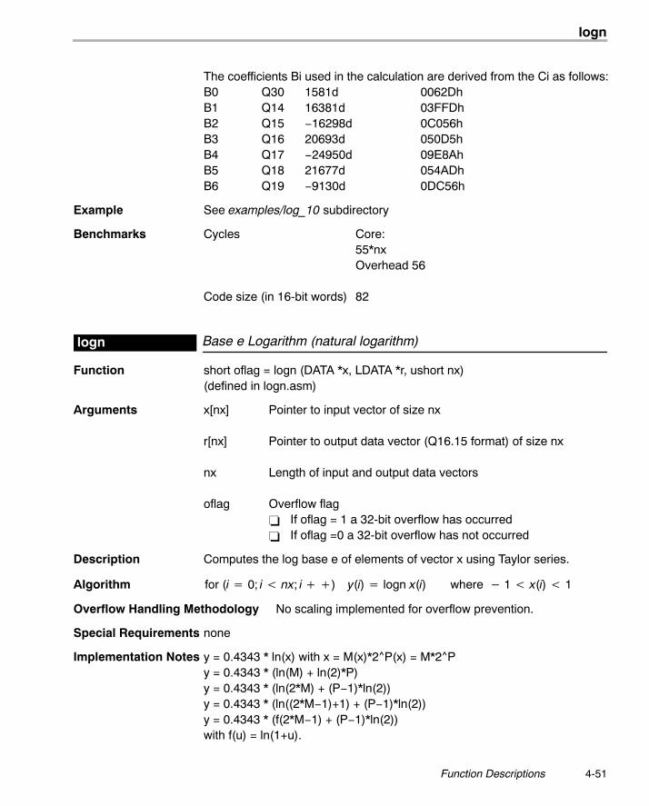
logn
4-51 Function Descriptions
The coefficients Bi used in the calculation are derived from the Ci as follows:B0 Q30 1581d 0062DhB1 Q14 16381d 03FFDhB2 Q15 −16298d 0C056hB3 Q16 20693d 050D5hB4 Q17 −24950d 09E8AhB5 Q18 21677d 054ADhB6 Q19 −9130d 0DC56h
Example See examples/log_10 subdirectory
Benchmarks Cycles Core:55*nxOverhead 56
Code size (in 16-bit words) 82
Base e Logarithm (natural logarithm)logn
Function short oflag = logn (DATA *x, LDATA *r, ushort nx)(defined in logn.asm)
Arguments x[nx] Pointer to input vector of size nx
r[nx] Pointer to output data vector (Q16.15 format) of size nx
nx Length of input and output data vectors
oflag Overflow flag� If oflag = 1 a 32-bit overflow has occurred� If oflag =0 a 32-bit overflow has not occurred
Description Computes the log base e of elements of vector x using Taylor series.
Algorithm for (i � 0; i nx; i ��) y(i) � logn x(i) where � 1 x(i) 1
Overflow Handling Methodology No scaling implemented for overflow prevention.
Special Requirements none
Implementation Notes y = 0.4343 * ln(x) with x = M(x)*2^P(x) = M*2^Py = 0.4343 * (ln(M) + ln(2)*P)y = 0.4343 * (ln(2*M) + (P−1)*ln(2))y = 0.4343 * (ln((2*M−1)+1) + (P−1)*ln(2))y = 0.4343 * (f(2*M−1) + (P−1)*ln(2))with f(u) = ln(1+u).
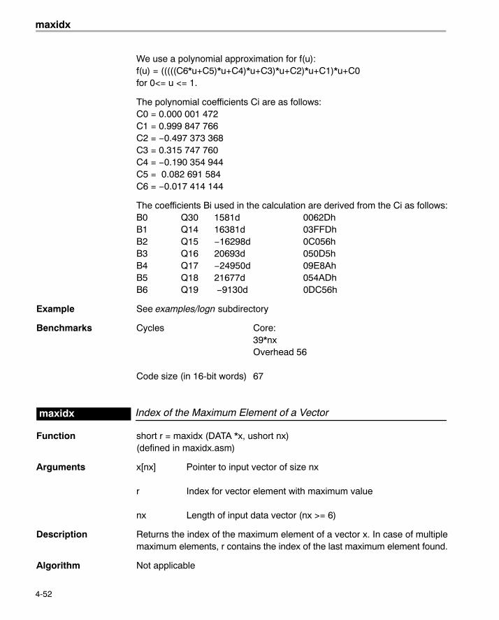
maxidx
4-52
We use a polynomial approximation for f(u):f(u) = (((((C6*u+C5)*u+C4)*u+C3)*u+C2)*u+C1)*u+C0for 0<= u <= 1.
The polynomial coefficients Ci are as follows:C0 = 0.000 001 472C1 = 0.999 847 766C2 = −0.497 373 368C3 = 0.315 747 760C4 = −0.190 354 944C5 = 0.082 691 584C6 = −0.017 414 144
The coefficients Bi used in the calculation are derived from the Ci as follows:B0 Q30 1581d 0062DhB1 Q14 16381d 03FFDhB2 Q15 −16298d 0C056hB3 Q16 20693d 050D5hB4 Q17 −24950d 09E8AhB5 Q18 21677d 054ADhB6 Q19 −9130d 0DC56h
Example See examples/logn subdirectory
Benchmarks Cycles Core:39*nxOverhead 56
Code size (in 16-bit words) 67
Index of the Maximum Element of a Vectormaxidx
Function short r = maxidx (DATA *x, ushort nx)(defined in maxidx.asm)
Arguments x[nx] Pointer to input vector of size nx
r Index for vector element with maximum value
nx Length of input data vector (nx >= 6)
Description Returns the index of the maximum element of a vector x. In case of multiplemaximum elements, r contains the index of the last maximum element found.
Algorithm Not applicable
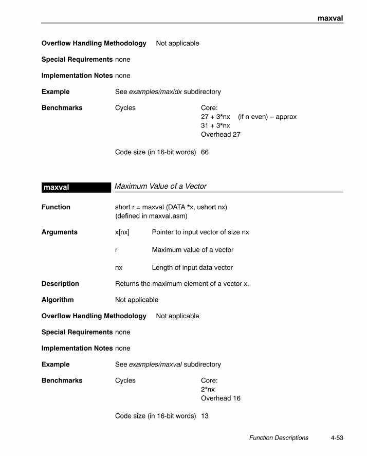
maxval
4-53 Function Descriptions
Overflow Handling Methodology Not applicable
Special Requirements none
Implementation Notes none
Example See examples/maxidx subdirectory
Benchmarks Cycles Core:27 + 3*nx (if n even) � approx31 + 3*nxOverhead 27
Code size (in 16-bit words) 66
Maximum Value of a Vectormaxval
Function short r = maxval (DATA *x, ushort nx)(defined in maxval.asm)
Arguments x[nx] Pointer to input vector of size nx
r Maximum value of a vector
nx Length of input data vector
Description Returns the maximum element of a vector x.
Algorithm Not applicable
Overflow Handling Methodology Not applicable
Special Requirements none
Implementation Notes none
Example See examples/maxval subdirectory
Benchmarks Cycles Core:2*nxOverhead 16
Code size (in 16-bit words) 13
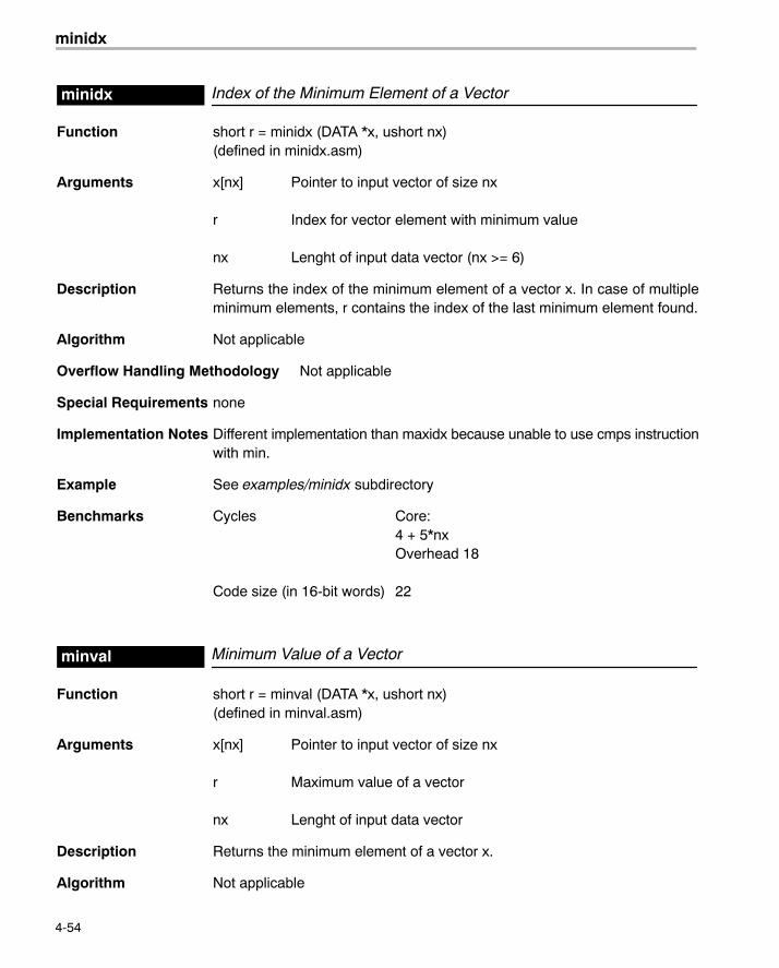
minidx
4-54
Index of the Minimum Element of a Vectorminidx
Function short r = minidx (DATA *x, ushort nx)(defined in minidx.asm)
Arguments x[nx] Pointer to input vector of size nx
r Index for vector element with minimum value
nx Lenght of input data vector (nx >= 6)
Description Returns the index of the minimum element of a vector x. In case of multipleminimum elements, r contains the index of the last minimum element found.
Algorithm Not applicable
Overflow Handling Methodology Not applicable
Special Requirements none
Implementation Notes Different implementation than maxidx because unable to use cmps instructionwith min.
Example See examples/minidx subdirectory
Benchmarks Cycles Core:4 + 5*nxOverhead 18
Code size (in 16-bit words) 22
Minimum Value of a Vectorminval
Function short r = minval (DATA *x, ushort nx)(defined in minval.asm)
Arguments x[nx] Pointer to input vector of size nx
r Maximum value of a vector
nx Lenght of input data vector
Description Returns the minimum element of a vector x.
Algorithm Not applicable
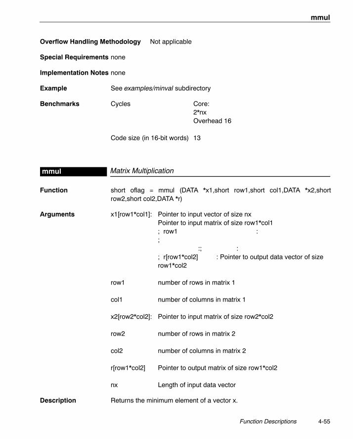
mmul
4-55 Function Descriptions
Overflow Handling Methodology Not applicable
Special Requirements none
Implementation Notes none
Example See examples/minval subdirectory
Benchmarks Cycles Core:2*nxOverhead 16
Code size (in 16-bit words) 13
Matrix Multiplicationmmul
Function short oflag = mmul (DATA *x1,short row1,short col1,DATA *x2,shortrow2,short col2,DATA *r)
Arguments x1[row1*col1]: Pointer to input vector of size nxPointer to input matrix of size row1*col1; row1 :; :; :; r[row1*col2] : Pointer to output data vector of sizerow1*col2
row1 number of rows in matrix 1
col1 number of columns in matrix 1
x2[row2*col2]: Pointer to input matrix of size row2*col2
row2 number of rows in matrix 2
col2 number of columns in matrix 2
r[row1*col2] Pointer to output matrix of size row1*col2
nx Length of input data vector
Description Returns the minimum element of a vector x.
mtrans
4-56
Algorithm Multiply input matrix A (M by N) by input matrix B (N by P) using 2 nested loops: for i = 1 to M for k = 1 to P { temp = 0 for j = 1 to N temp = temp + A(i,j) * B(j,k) C(i,k) = temp }
Overflow Handling Methodology Not applicable
Special Requirements Verify that the dimensions of input matrices are legal.
Implementation Notes none
Example See examples/minval subdirectory
Benchmarks Cycles Core:row1*(7+(11+(6*col1))*col2)Overhead 71
Code size (in 16-bit words) 65
Matrix Transposemtrans
Function short oflag = mtrans(DATA *x, DATA *r, ushort nx)(defined in mtrans.asm)
Arguments x[row*col] Pointer to input matrix. In-place processing is not allowed.
row Number of rows in matrix
col Number of columns in matrix
r[row*col] Pointer to output data vector of size nx containing
Description This function transponse matrix x.
Algorithm for i = 1 to M for j = 1 to N C(j,i) = A(i,j)
Overflow Handling Methodology Scaling implemented for overflow prevention (user selectable).
Special Requirements none
mul32
4-57 Function Descriptions
Implementation Notes none
Example See examples/mtrans subdirectory
Benchmarks Cycles Core:[5+(col*6)]Overhead 44
Code size (in 16-bit words) 34
32-bit Vector Multiplymul32
Function short oflag = mul32(LDATA *x, LDATA *y, LDATA *r, ushort nx)(defined in mul32.asm)
Arguments x[nx] Pointer to input data vector 1 of size nx. In-place processingallowed (r can be = x = y).
y[nx] Pointer to input data vector 2 of size nx
r[nx] Pointer to output data vector of size nx containing
nx Number of elements of input and output vectorsnx >=4
oflag Overflow flag� If oflag = 1 a 32-bit overflow has occurred� If oflag =0 a 32-bit overflow has not occurred
Description This function multiply two 2 32-bit Q31 vectors, element by element, and pro-duce a 32-bit Q31 vector.
Algorithm for (i=0; i < nx; i++)z (i) = x (i) * y (i)
Overflow Handling Methodology Scaling implemented for overflow prevention (User selectable)
Special Requirements none
Implementation Notes none
Example See examples/add subdirectory
Benchmarks Cycles Core:7*nx + 4Overhead 29
Code size (in 16-bit words) 35
nblms
4-58
Normalized Block LMS Block Filternblms
Function short oflag = nblms (DATA *x,DATA *h,DATA *r, DATA **dbuffer, DATA *des,ushort nh, ushort nx, ushort nb, DATA **norm_e, int l_tau, int cutoff, int gain)(defined in nblms.asm)
Arguments x[nx] Input data vector of size nx (reference input)
h(nh) Pointer to filter coefficient vector of size nh� h is stored in reversed order: h(n−1), ... h(0) where h[n] is at
the lowest memory address.� Memory alignment: h is a circular buffer and must start in a
k-bit boundary (that is, the k LSBs of the starting address mustbe zeros) where k = log2(nh).
r[nx] Pointer to output data vector of size nx. r can be equal to x.
dbuffer[nh] Pointer to location containing the address of the delay buffer.Memory alignment: the delay buffer is a circular buffer and muststart in a k-bit boundary (that is, the k LSBs of the starting addressmust be zeros) where k = log2(nh).
des[nx] Pointer to expected output array
nh Number of filter coefficients. Filter order = nh−1. nh >=3
nx Length of input and output data vectors
nb number of blocks
bsize blocksize (number of coefficients to be updated for each inputsample)Note: nh (number of coefficients) = nb*bsize
norm_e pointer to normalized error buffer
l_tau decay constant for long-term filtering of power estimate
cutoff the lowest allowed value for power estimate
gain step size constant: 2*beta= beta1/abs_power = 2^(gain) /abs_power
nblms
4-59 Function Descriptions
oflag Overflow flag� If oflag = 1 a 32-bit overflow has occurred� If oflag =0 a 32-bit overflow has not occurred
Description Normalized Delayed LMS (NDLMS) Block FIR implementation using coeffi-cients stored in vector h. Coefficients are updated after each sample based onthe LMS algorithm. The real data input is stored in vector a. The filter outputresult is stored in vector r.
LMS algorithm is used but adaptation uses the previous error and the previoussample (�delayed�) and takes advantage of the C54x LMS instruction.
Restrictions: This version does not allow consecutive calls to this routine in adual buffering fashion.
Algorithm For a more detailed description of the algorithm, refer to [4].
FIR portion r[i] � �nh�1
k�0
b[k] * x[i � k] 0 � i � nx
Adaptation using the previous error and the previous samplee(i) = d(i) − y(i); (error)var(i) = (1−�) * var(i−1) + �*[abs(x(i)) + cutoff]; (signal power estimate)
for (j � 0 : j nb; j ��)
{
bkj(i � 1) �bkj(i) � [2 * � * e(i) * x(i � k)]
[var(i) � 2]}
Overflow Handling Methodology No scaling implemented for overflow prevention.
Special Requirements Linker command file: you must allocate .ebuffer section (for polynomial coeffi-cients).
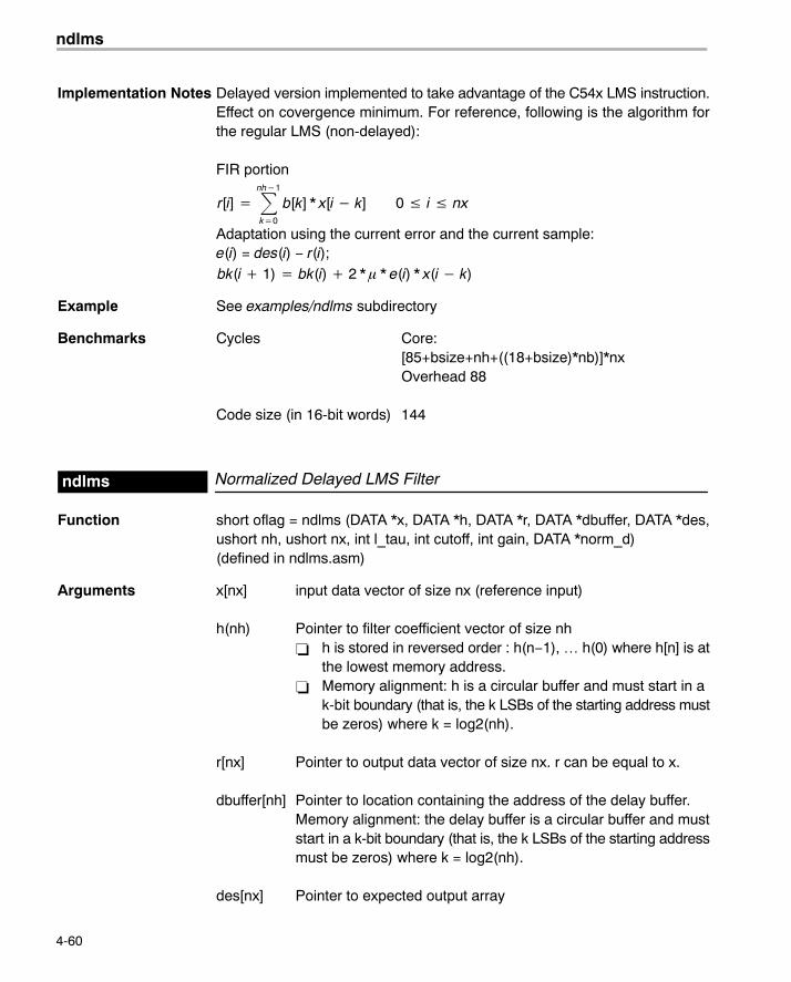
ndlms
4-60
Implementation Notes Delayed version implemented to take advantage of the C54x LMS instruction.Effect on covergence minimum. For reference, following is the algorithm forthe regular LMS (non-delayed):
FIR portion
r[i] � �nh�1
k�0
b[k] * x[i � k] 0 � i � nx
Adaptation using the current error and the current sample:e(i) = des(i) − r(i);bk(i � 1) � bk(i) � 2 * � * e(i) * x(i � k)
Example See examples/ndlms subdirectory
Benchmarks Cycles Core:[85+bsize+nh+((18+bsize)*nb)]*nxOverhead 88
Code size (in 16-bit words) 144
Normalized Delayed LMS Filterndlms
Function short oflag = ndlms (DATA *x, DATA *h, DATA *r, DATA *dbuffer, DATA *des,ushort nh, ushort nx, int l_tau, int cutoff, int gain, DATA *norm_d)(defined in ndlms.asm)
Arguments x[nx] input data vector of size nx (reference input)
h(nh) Pointer to filter coefficient vector of size nh� h is stored in reversed order : h(n−1), … h(0) where h[n] is at
the lowest memory address.� Memory alignment: h is a circular buffer and must start in a
k-bit boundary (that is, the k LSBs of the starting address mustbe zeros) where k = log2(nh).
r[nx] Pointer to output data vector of size nx. r can be equal to x.
dbuffer[nh] Pointer to location containing the address of the delay buffer.Memory alignment: the delay buffer is a circular buffer and muststart in a k-bit boundary (that is, the k LSBs of the starting addressmust be zeros) where k = log2(nh).
des[nx] Pointer to expected output array
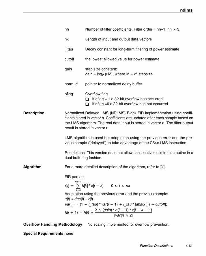
ndlms
4-61 Function Descriptions
nh Number of filter coefficients. Filter order = nh−1. nh >=3
nx Length of input and output data vectors
l_tau Decay constant for long-term filtering of power estimate
cutoff the lowest allowed value for power estimate
gain step size constant:gain = log2 (2M), where M = 2* stepsize
norm_d pointer to normalized delay buffer
oflag Overflow flag� If oflag = 1 a 32-bit overflow has occurred� If oflag =0 a 32-bit overflow has not occurred
Description Normalized Delayed LMS (NDLMS) Block FIR implementation using coeffi-cients stored in vector h. Coefficients are updated after each sample based onthe LMS algorithm. The real data input is stored in vector a. The filter outputresult is stored in vector r.
LMS algorithm is used but adaptation using the previous error and the pre-vious sample (�delayed�) to take advantage of the C54x LMS instruction.
Restrictions: This version does not allow consecutive calls to this routine in adual buffering fashion.
Algorithm For a more detailed description of the algorithm, refer to [4].
FIR portion
r[i] � �nh�1
k�0
h[k] * x[i � k] 0 � i � nx
Adaptation using the previous error and the previous sample:e(i) = des(i) − r(i)var(i) � (1 � l_tau) * var(i � 1) � l_tau * [abs(x(i)) � cutoff];
h(i � 1) � h(i) �2 � (gain) * e(i � 1) * x(i � k � 1)
[var(i) � 2]
Overflow Handling Methodology No scaling implemented for overflow prevention.
Special Requirements none
neg
4-62
Implementation Notes Delayed version implemented to take advantage of the C54x LMS instruction.Effect on covergence minimum.
Example See examples/ndlms subdirectory
Benchmarks Cycles Core:[63+(nh−1)*2]*nxOverhead 52
Code size (in 16-bit words) 144
Vector Negateneg
Function short oflag = neg (DATA *x, DATA *r, ushort nx)(defined in neg.asm)
Arguments x[nx] Pointer to input data vector 1 of size nx. In-place processingallowed (r can be = x = y)
r[nx] Pointer to output data vector of size nx. In-place processingallowedSpecial cases:� if x[I] = −1 = 32768, then r = 1 = 321767 with oflag = 1� if x= 1 = 32767, then r = −1 = 321768 with oflag = 1
nx Number of elements of input and output vectorsnx >=4
oflag Overflow flag� If oflag = 1 a 32-bit overflow has occurred� If oflag =0 a 32-bit overflow has not occurredThis shoud be taken it as a warning: overflow in negation of a Q15number can happen naturally when negating (−1).
Description This function negates each of the elements of a vector (fractional values).
Algorithm for (i=0; i < nx; i++)x(i) = −x(i)
Overflow Handling Methodology Saturation implemented for overflow handling.
Special Requirements none
Implementation Notes none
Example See examples/neg subdirectory
neg32
4-63 Function Descriptions
Benchmarks Cycles Core:2*(nx−1)Overhead 30
Code size (in 16-bit words) 21
Vector Negate (double-precision)neg32
Function short oflag = neg32 (LDATA *x, LDATA *r, ushort nx)(defined in neg32.asm)
Arguments x[nx] Pointer to input data vector 1 of size nx. In-place processingallowed (r can be = x = y)
r[nx] Pointer to output data vector of size nx. In-place processingallowedSpecial cases:� if x= −1 = 32768*2^16 , then r = 1 = 321767*2^16
with oflag = 1� if x= 1 = 32767*2^16 , then \ r = −1 = 321768*2^16
with oflag = 1
nx Number of elements of input and output vectorsnx >=4
oflag Overflow flag� If oflag = 1 a 32-bit overflow has occurred� If oflag =0 a 32-bit overflow has not occurredThis should be take it as a warning: overflow in negation of a Q31number can happen naturally when negating (−1).
Description This function negates each of the elements of a vector (fractional values).
Algorithm for (i=0; i < nx; i++)x(i) = −x(i)
Overflow Handling Methodology Saturation implemented for overflow handling.
Special Requirements none
Implementation Notes none
Example See examples/neg32 subdirectory
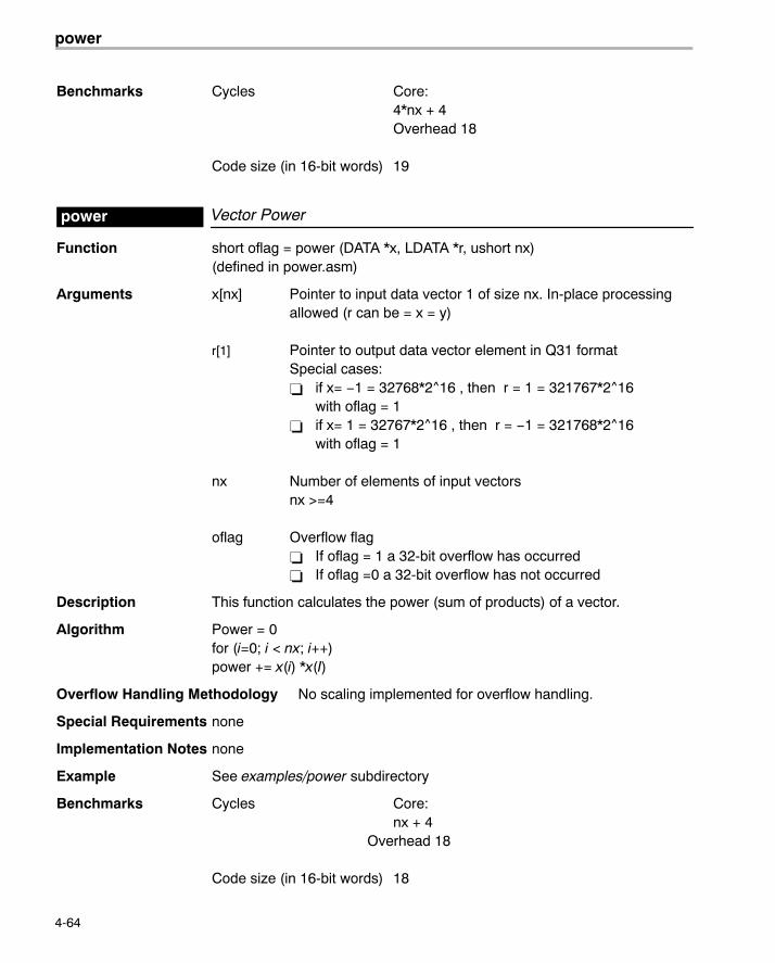
power
4-64
Benchmarks Cycles Core:4*nx + 4Overhead 18
Code size (in 16-bit words) 19
Vector Powerpower
Function short oflag = power (DATA *x, LDATA *r, ushort nx)(defined in power.asm)
Arguments x[nx] Pointer to input data vector 1 of size nx. In-place processingallowed (r can be = x = y)
r[1] Pointer to output data vector element in Q31 formatSpecial cases:� if x= −1 = 32768*2^16 , then r = 1 = 321767*2^16
with oflag = 1� if x= 1 = 32767*2^16 , then r = −1 = 321768*2^16
with oflag = 1
nx Number of elements of input vectorsnx >=4
oflag Overflow flag� If oflag = 1 a 32-bit overflow has occurred� If oflag =0 a 32-bit overflow has not occurred
Description This function calculates the power (sum of products) of a vector.
Algorithm Power = 0for (i=0; i < nx; i++)power += x(i) *x(I)
Overflow Handling Methodology No scaling implemented for overflow handling.
Special Requirements none
Implementation Notes none
Example See examples/power subdirectory
Benchmarks Cycles Core:nx + 4
Overhead 18
Code size (in 16-bit words) 18
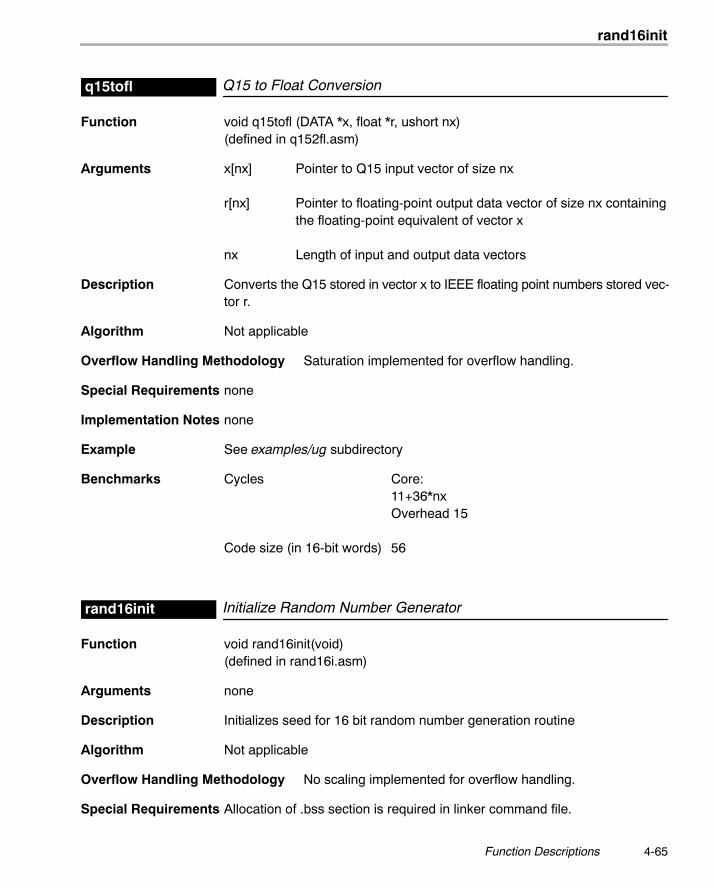
rand16init
4-65 Function Descriptions
Q15 to Float Conversionq15tofl
Function void q15tofl (DATA *x, float *r, ushort nx)(defined in q152fl.asm)
Arguments x[nx] Pointer to Q15 input vector of size nx
r[nx] Pointer to floating-point output data vector of size nx containingthe floating-point equivalent of vector x
nx Length of input and output data vectors
Description Converts the Q15 stored in vector x to IEEE floating point numbers stored vec-tor r.
Algorithm Not applicable
Overflow Handling Methodology Saturation implemented for overflow handling.
Special Requirements none
Implementation Notes none
Example See examples/ug subdirectory
Benchmarks Cycles Core:11+36*nxOverhead 15
Code size (in 16-bit words) 56
Initialize Random Number Generatorrand16init
Function void rand16init(void)(defined in rand16i.asm)
Arguments none
Description Initializes seed for 16 bit random number generation routine
Algorithm Not applicable
Overflow Handling Methodology No scaling implemented for overflow handling.
Special Requirements Allocation of .bss section is required in linker command file.
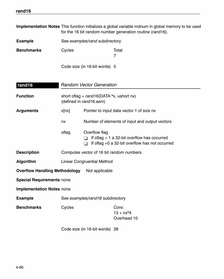
rand16
4-66
Implementation Notes This function initializes a global variable rndnum in global memory to be usedfor the 16 bit random number generation routine (rand16).
Example See examples/rand subdirectory
Benchmarks Cycles Total7
Code size (in 16-bit words) 5
Random Vector Generationrand16
Function short oflag = rand16(DATA *x, ushort nx)(defined in rand16.asm)
Arguments x[nx] Pointer to input data vector 1 of size nx
nx Number of elements of input and output vectors
oflag Overflow flag� If oflag = 1 a 32-bit overflow has occurred� If oflag =0 a 32-bit overflow has not occurred
Description Computes vector of 16 bit random numbers.
Algorithm Linear Congruential Method
Overflow Handling Methodology Not applicable
Special Requirements none
Implementation Notes none
Example See examples/rand16 subdirectory
Benchmarks Cycles Core:13 + nx*4Overhead 10
Code size (in 16-bit words) 28
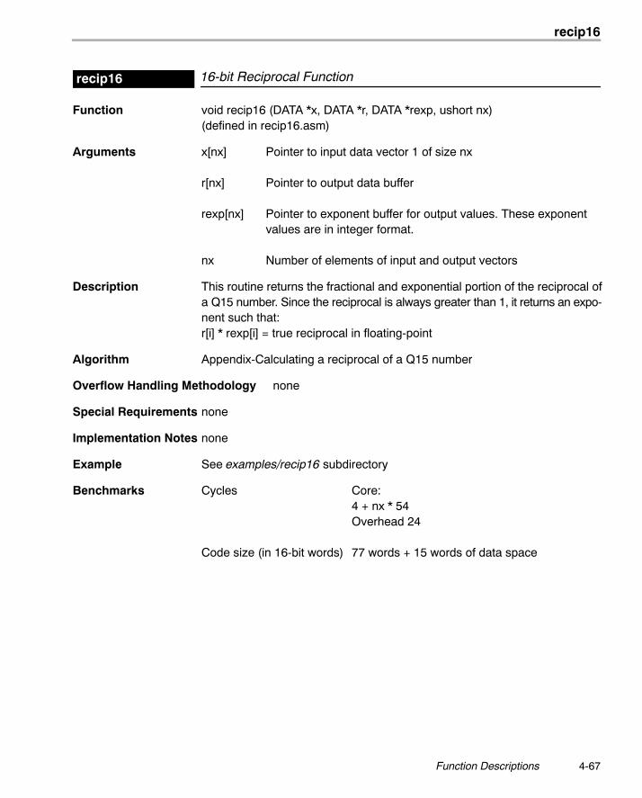
recip16
4-67 Function Descriptions
16-bit Reciprocal Functionrecip16
Function void recip16 (DATA *x, DATA *r, DATA *rexp, ushort nx)(defined in recip16.asm)
Arguments x[nx] Pointer to input data vector 1 of size nx
r[nx] Pointer to output data buffer
rexp[nx] Pointer to exponent buffer for output values. These exponentvalues are in integer format.
nx Number of elements of input and output vectors
Description This routine returns the fractional and exponential portion of the reciprocal ofa Q15 number. Since the reciprocal is always greater than 1, it returns an expo-nent such that:r[i] * rexp[i] = true reciprocal in floating-point
Algorithm Appendix-Calculating a reciprocal of a Q15 number
Overflow Handling Methodology none
Special Requirements none
Implementation Notes none
Example See examples/recip16 subdirectory
Benchmarks Cycles Core:4 + nx * 54Overhead 24
Code size (in 16-bit words) 77 words + 15 words of data space
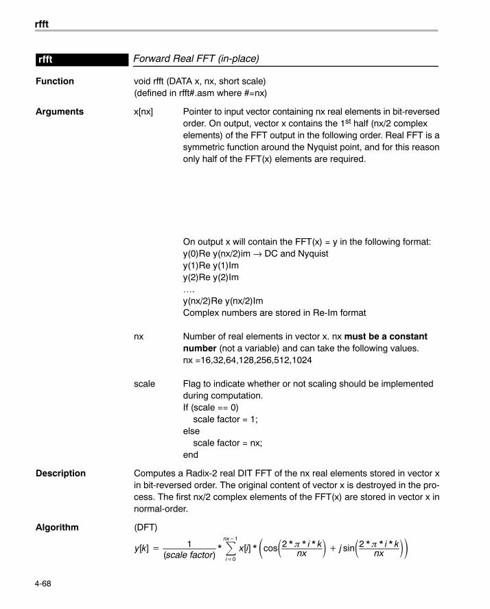
rfft
4-68
Forward Real FFT (in-place)rfft
Function void rfft (DATA x, nx, short scale)(defined in rfft#.asm where #=nx)
Arguments x[nx] Pointer to input vector containing nx real elements in bit-reversedorder. On output, vector x contains the 1st half (nx/2 complexelements) of the FFT output in the following order. Real FFT is asymmetric function around the Nyquist point, and for this reasononly half of the FFT(x) elements are required.
On output x will contain the FFT(x) = y in the following format:y(0)Re y(nx/2)im → DC and Nyquisty(1)Re y(1)Imy(2)Re y(2)Im….y(nx/2)Re y(nx/2)ImComplex numbers are stored in Re-Im format
nx Number of real elements in vector x. nx must be a constantnumber (not a variable) and can take the following values.nx =16,32,64,128,256,512,1024
scale Flag to indicate whether or not scaling should be implementedduring computation.If (scale == 0) scale factor = 1;else scale factor = nx;end
Description Computes a Radix-2 real DIT FFT of the nx real elements stored in vector xin bit-reversed order. The original content of vector x is destroyed in the pro-cess. The first nx/2 complex elements of the FFT(x) are stored in vector x innormal-order.
Algorithm (DFT)
y[k] � 1(scale factor)
* �nx�1
i�0
x[i] * �cos�2 * � * i * knx
� � j sin�2 * � * i * knx
��
rfft
4-69 Function Descriptions
Overflow Handling Methodology Scaling implemented for overflow prevention (See section 6.3)
Special Requirements� Special linker command file sections required: .sintab (containing the
twiddle table). For .sintab section size refer to the benchmark informationbelow.
� This function requires the inclusion of two other files during assembling(automatically included):
� macros.asm (contains all macros used for this code)
� sintab.q15 (contains twiddle table section .sintab)
� unpack.asm (containing code to for unpacking results)
� Memory alignment: Although there is no memory alignment request forthis function, you need to align input data if you use this function with func-tion cbrev (see page 4-13).
Implementation Notes� Implemented as a complex FFT of size nx/2 followed by an unpack stage
to unpack the real FFT results. Therefore, implementation notes for the cfftfunction apply to this case. For this reason, you must use the complex bitreverse.
� Notice that normally an FFT of a real sequence of size N, produces a com-plex sequence of size N (or 2*N real numbers) that will not fit in the inputsequence. To accomodate all the results without requiring extra memorylocations, the output reflects only half of the spectrum (complex output).This still provides the full information because an FFT of a real sequencehas even symmetry around the center or nyquist point(N/2).
� Special debugging consideration: This function is implemented as a mac-ro that invokes different FFT routines according to the size. As a conse-quence, instead of the rfft symbol being defined, multiple rfft# symbols are(where # = nx = FFT real size)
� When scale = 1, this routine prevents overflow by scaling by 2 at each FFTintermediate stages and at the unpacking stage.
Example See examples/rfft subdirectory
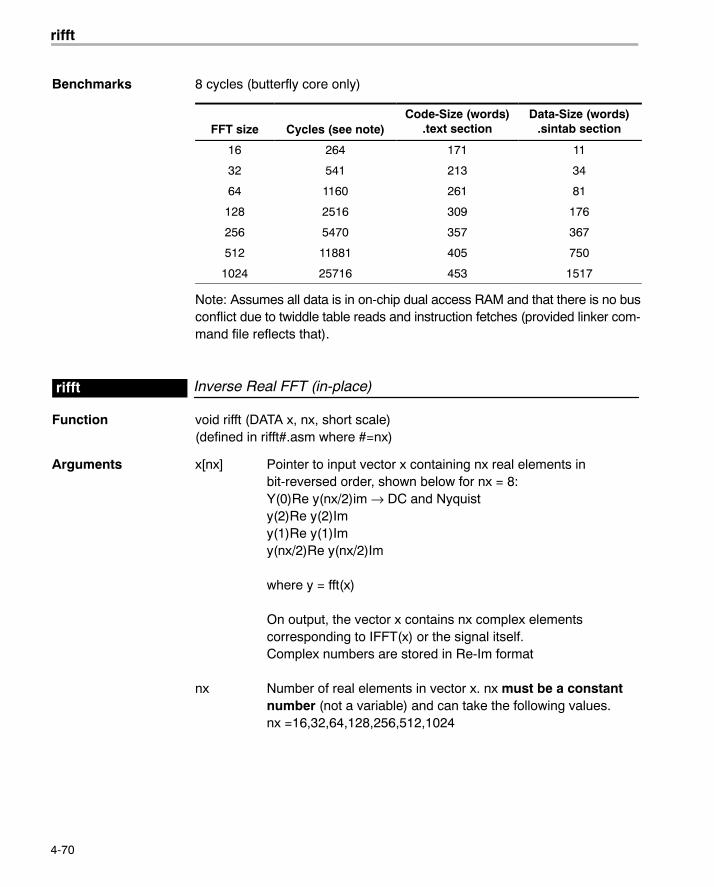
rifft
4-70
Benchmarks 8 cycles (butterfly core only)
FFT size Cycles (see note)Code-Size (words)
.text sectionData-Size (words)
.sintab section
16 264 171 11
32 541 213 34
64 1160 261 81
128 2516 309 176
256 5470 357 367
512 11881 405 750
1024 25716 453 1517
Note: Assumes all data is in on-chip dual access RAM and that there is no busconflict due to twiddle table reads and instruction fetches (provided linker com-mand file reflects that).
Inverse Real FFT (in-place)rifft
Function void rifft (DATA x, nx, short scale)(defined in rifft#.asm where #=nx)
Arguments x[nx] Pointer to input vector x containing nx real elements inbit-reversed order, shown below for nx = 8:Y(0)Re y(nx/2)im → DC and Nyquisty(2)Re y(2)Imy(1)Re y(1)Imy(nx/2)Re y(nx/2)Im
where y = fft(x)
On output, the vector x contains nx complex elementscorresponding to IFFT(x) or the signal itself.Complex numbers are stored in Re-Im format
nx Number of real elements in vector x. nx must be a constantnumber (not a variable) and can take the following values.nx =16,32,64,128,256,512,1024
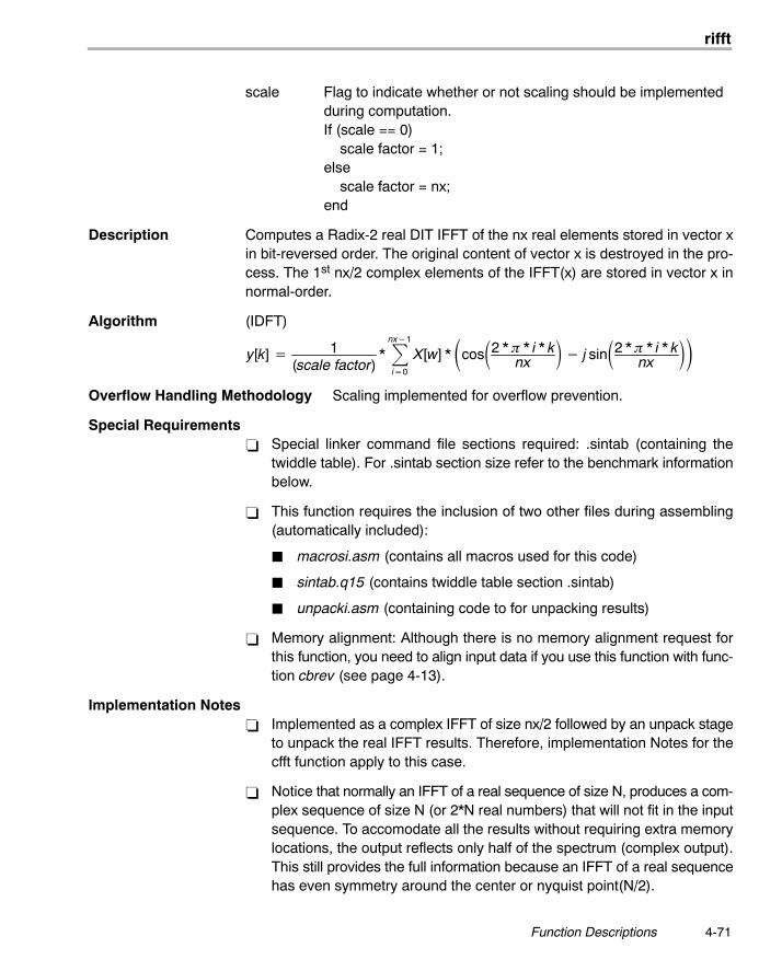
rifft
4-71 Function Descriptions
scale Flag to indicate whether or not scaling should be implementedduring computation.If (scale == 0) scale factor = 1;else scale factor = nx;end
Description Computes a Radix-2 real DIT IFFT of the nx real elements stored in vector xin bit-reversed order. The original content of vector x is destroyed in the pro-cess. The 1st nx/2 complex elements of the IFFT(x) are stored in vector x innormal-order.
Algorithm (IDFT)
y[k] � 1(scale factor)
* �nx�1
i�0
X[w] * �cos�2 * � * i * knx
� � j sin�2 * � * i * knx
��Overflow Handling Methodology Scaling implemented for overflow prevention.
Special Requirements� Special linker command file sections required: .sintab (containing the
twiddle table). For .sintab section size refer to the benchmark informationbelow.
� This function requires the inclusion of two other files during assembling(automatically included):
� macrosi.asm (contains all macros used for this code)
� sintab.q15 (contains twiddle table section .sintab)
� unpacki.asm (containing code to for unpacking results)
� Memory alignment: Although there is no memory alignment request forthis function, you need to align input data if you use this function with func-tion cbrev (see page 4-13).
Implementation Notes� Implemented as a complex IFFT of size nx/2 followed by an unpack stage
to unpack the real IFFT results. Therefore, implementation Notes for thecfft function apply to this case.
� Notice that normally an IFFT of a real sequence of size N, produces a com-plex sequence of size N (or 2*N real numbers) that will not fit in the inputsequence. To accomodate all the results without requiring extra memorylocations, the output reflects only half of the spectrum (complex output).This still provides the full information because an IFFT of a real sequencehas even symmetry around the center or nyquist point(N/2).
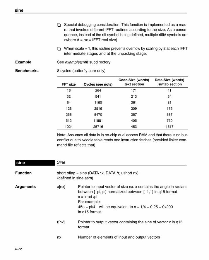
sine
4-72
� Special debugging consideration: This function is implemented as a mac-ro that invokes different IFFT routines according to the size. As a conse-quence, instead of the rfft symbol being defined, multiple rifft# symbols are(where # = nx = IFFT real size)
� When scale = 1, this routine prevents overflow by scaling by 2 at each IFFTintermediate stages and at the unpacking stage.
Example See examples/rifft subdirectory
Benchmarks 8 cycles (butterfly core only)
FFT size Cycles (see note)Code-Size (words)
.text sectionData-Size (words)
.sintab section
16 264 171 11
32 541 213 34
64 1160 261 81
128 2516 309 176
256 5470 357 367
512 11881 405 750
1024 25716 453 1517
Note: Assumes all data is in on-chip dual access RAM and that there is no busconflict due to twiddle table reads and instruction fetches (provided linker com-mand file reflects that).
Sinesine
Function short oflag = sine (DATA *x, DATA *r, ushort nx)(defined in sine.asm)
Arguments x[nx] Pointer to input vector of size nx. x contains the angle in radiansbetween [−pi, pi] normalized between [−1,1) in q15 formatx = xrad /piFor example:45o = pi/4 will be equivalent to x = 1/4 = 0.25 = 0x200in q15 format.
r[nx] Pointer to output vector containing the sine of vector x in q15format
nx Number of elements of input and output vectors
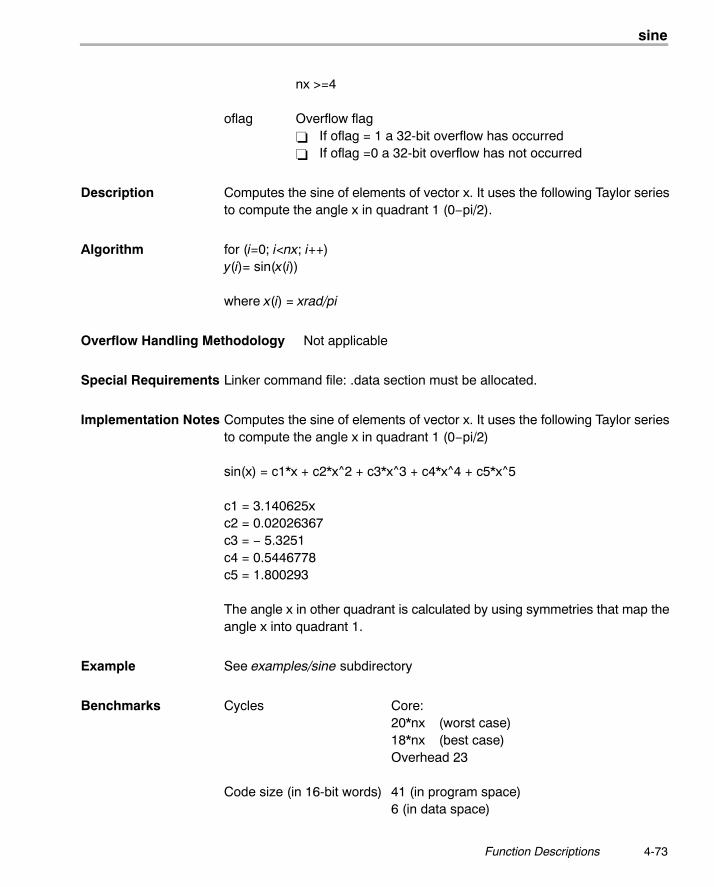
sine
4-73 Function Descriptions
nx >=4
oflag Overflow flag� If oflag = 1 a 32-bit overflow has occurred� If oflag =0 a 32-bit overflow has not occurred
Description Computes the sine of elements of vector x. It uses the following Taylor seriesto compute the angle x in quadrant 1 (0−pi/2).
Algorithm for (i=0; i<nx; i++)y(i)= sin(x(i))
where x(i) = xrad/pi
Overflow Handling Methodology Not applicable
Special Requirements Linker command file: .data section must be allocated.
Implementation Notes Computes the sine of elements of vector x. It uses the following Taylor seriesto compute the angle x in quadrant 1 (0−pi/2)
sin(x) = c1*x + c2*x^2 + c3*x^3 + c4*x^4 + c5*x^5
c1 = 3.140625xc2 = 0.02026367c3 = − 5.3251c4 = 0.5446778c5 = 1.800293
The angle x in other quadrant is calculated by using symmetries that map theangle x into quadrant 1.
Example See examples/sine subdirectory
Benchmarks Cycles Core:20*nx (worst case)18*nx (best case)Overhead 23
Code size (in 16-bit words) 41 (in program space)6 (in data space)
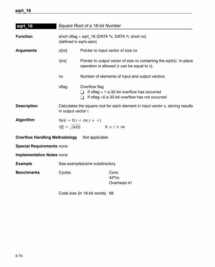
sqrt_16
4-74
Square Root of a 16-bit Numbersqrt_16
Function short oflag = sqrt_16 (DATA *x, DATA *r, short nx)(defined in sqrtv.asm)
Arguments x[nx] Pointer to input vector of size nx
r[nx] Pointer to output vector of size nx containing the sqrt(x). In-placeoperation is allowed (r can be equal to x).
nx Number of elements of input and output vectors
oflag Overflow flag� If oflag = 1 a 32-bit overflow has occurred� If oflag =0 a 32-bit overflow has not occurred
Description Calculates the square root for each element in input vector x, storing resultsin output vector r.
Algorithm for(i � 0; i nx; i ��)
r[i] � (x(i))� 0 � i � nx
Overflow Handling Methodology Not applicable
Special Requirements none
Implementation Notes none
Example See examples/sine subdirectory
Benchmarks Cycles Core:42*nxOverhead 41
Code size (in 16-bit words) 68
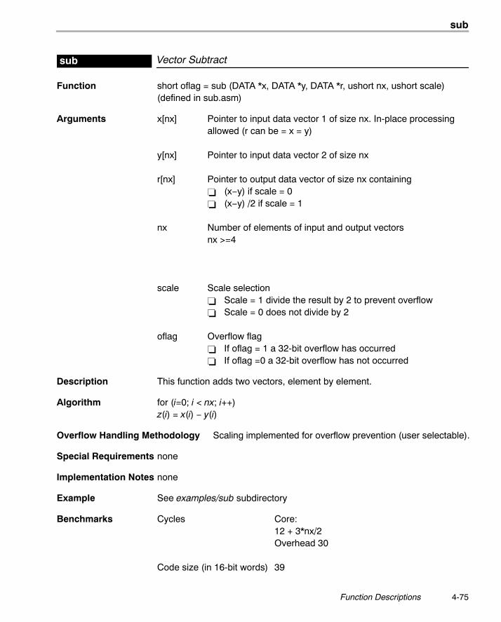
sub
4-75 Function Descriptions
Vector Subtractsub
Function short oflag = sub (DATA *x, DATA *y, DATA *r, ushort nx, ushort scale)(defined in sub.asm)
Arguments x[nx] Pointer to input data vector 1 of size nx. In-place processingallowed (r can be = x = y)
y[nx] Pointer to input data vector 2 of size nx
r[nx] Pointer to output data vector of size nx containing� (x−y) if scale = 0� (x−y) /2 if scale = 1
nx Number of elements of input and output vectorsnx >=4
scale Scale selection� Scale = 1 divide the result by 2 to prevent overflow� Scale = 0 does not divide by 2
oflag Overflow flag� If oflag = 1 a 32-bit overflow has occurred� If oflag =0 a 32-bit overflow has not occurred
Description This function adds two vectors, element by element.
Algorithm for (i=0; i < nx; i++)z(i) = x(i) − y(i)
Overflow Handling Methodology Scaling implemented for overflow prevention (user selectable).
Special Requirements none
Implementation Notes none
Example See examples/sub subdirectory
Benchmarks Cycles Core:12 + 3*nx/2Overhead 30
Code size (in 16-bit words) 39

sub
4-76
5-1
DSPLIB Benchmarks and Performance Issues
All functions in the DSPLIB are provided with execution time and code sizebenchmarks. While developing the included functions, we tried to compromisebetween speed, code size and ease of use. However with few exceptions, thehighest priority was given to optimize for speed and ease-of-use, and last forcode size.
Even though DSPLIB can be used as a first estimation of processor perfor-mance for an specific function, you should have in mind that the generic natureof DSPLIB might add extra cycles not required for customer specific use.
Topic Page
5.1 What DSPLIB Benchmarks are Provided 5-2. . . . . . . . . . . . . . . . . . . . . . . .
5.2 Performance Considerations 5-2. . . . . . . . . . . . . . . . . . . . . . . . . . . . . . . . . . .
Chapter 5
What DSPLIB Benchmarks are Provided
5-2
5.1 What DSPLIB Benchmarks are Provided
DSPLIB documentation includes benchmarks for instruction cycles andmemory consumption. The following benchmarks are typically included:
� Calling and register initialization overhead
� Number of cycles in the kernel code: Typically provided in the form of anequation that is a function of the data size parameters. We consider thekernel (or core) code, the instructions contained between the _start and_end labels that you can see in each of the functions
� Memory consumption: Typically program size in 16-bit words is reported.For functions requiring significant internal data allocation, data memoryconsumption is also provided. When stack usage for local variables isminimum, that data consumption is not reported.
For functions in which is difficult to determine the number of cycles in the kernelcode as a function of the data size parameters, we have included direct cyclecount for specific data sizes.
5.2 Performance Considerations
Benchmark cycles presented assume best case conditions, typically assum-ing: 0-wait state memory external memory for program and data data alloca-tion to on-chip DARAM no-pipeline hits.
A linker command file showing the memory allocation used during testing andbenchmarking in the TI C54x EVM is included under the example subdirectory.
Remember, execution speed in a system is dependent on where the differentsections of program and data are located in memory. Be sure to account forsuch differences, when trying to explain why a routine is taking more time thatthe reported DSPLIB benchmarks.
6-1
Software Updates and Customer Support
This chapter details the software updates and customer support issues for theTMS320C55x DSPLIB.
Topic Page
6.1 DSPLIB Software Updates 6-2. . . . . . . . . . . . . . . . . . . . . . . . . . . . . . . . . . . . .
6.2 DSPLIB Customer Support 6-2. . . . . . . . . . . . . . . . . . . . . . . . . . . . . . . . . . . .
Chapter 6
DSPLIB Software Updates
6-2
6.1 DSPLIB Software Updates
C54x DSPLIB software updates will be periodically released, incorporatingproduct enhancement and fixes.
DSPLIB software updates will be posted as they become available in the samelocation you download this information. Source code for previous releases willbe kept public to prevent any customer problem in case we decide to discontin-ue or change the functionality of one of the DSPLIB functions. Make sure toread the readme.1st file available in the root directory of every release.
6.2 DSPLIB Customer Support
If you have question or want to report problems or suggestions regarding theC54x DSPLIB, contact Texas Instruments at [email protected]. We encourage theuse of the software report form (report.txt) contained in the DSPLIB doc direc-tory to report any problem associated with the C54xDSPLIB.
A-1
Appendix A
Overview of Fractional Q Formats
Unless specifically noted, DSPLIB functions use Q15 format or to be more ex-act Q0.15. In a Qm.n format, there are m bits used to represent the twos com-plement integer portion of the number, and n bits used to represent the twoscomplement fractional portion. m+n+1 bits are needed to store a general Qm.nnumber. The extra bit is needed to store the sign of the number in the most-sig-nificant bit position. The representable integer range is specified by (−2m,2m)and the finest fractional resolution is 2−n.
For example, the most commonly used format is Q.15. Q.15 means that a16-bit word is used to express a signed number between positive and negativeone. The most-significant binary digit is interpreted as the sign bit in any Q for-mat number. Thus in Q.15 format, the decimal point is placed immediately tothe right of the sign bit. The fractional portion to the right of the sign bit is storedin regular twos complement format.
Topic Page
A.1 Q3.12 Format A-2. . . . . . . . . . . . . . . . . . . . . . . . . . . . . . . . . . . . . . . . . . . . . . . . .
A.2 Q.15 Format A-2. . . . . . . . . . . . . . . . . . . . . . . . . . . . . . . . . . . . . . . . . . . . . . . . . .
A.3 Q.31 Format A-2. . . . . . . . . . . . . . . . . . . . . . . . . . . . . . . . . . . . . . . . . . . . . . . . . .
Appendix A
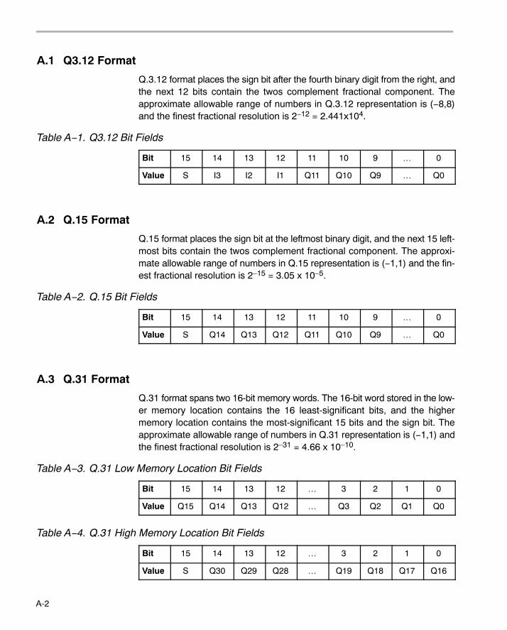
A-2
A.1 Q3.12 Format
Q.3.12 format places the sign bit after the fourth binary digit from the right, andthe next 12 bits contain the twos complement fractional component. Theapproximate allowable range of numbers in Q.3.12 representation is (−8,8)and the finest fractional resolution is 2−12 = 2.441x10⁴.
Table A−1. Q3.12 Bit Fields
Bit 15 14 13 12 11 10 9 … 0
Value S I3 I2 I1 Q11 Q10 Q9 … Q0
A.2 Q.15 Format
Q.15 format places the sign bit at the leftmost binary digit, and the next 15 left-most bits contain the twos complement fractional component. The approxi-mate allowable range of numbers in Q.15 representation is (−1,1) and the fin-est fractional resolution is 2�15 = 3.05 x 10�5.
Table A−2. Q.15 Bit Fields
Bit 15 14 13 12 11 10 9 … 0
Value S Q14 Q13 Q12 Q11 Q10 Q9 … Q0
A.3 Q.31 Format
Q.31 format spans two 16-bit memory words. The 16-bit word stored in the low-er memory location contains the 16 least-significant bits, and the highermemory location contains the most-significant 15 bits and the sign bit. Theapproximate allowable range of numbers in Q.31 representation is (−1,1) andthe finest fractional resolution is 2�31 = 4.66 x 10�10.
Table A−3. Q.31 Low Memory Location Bit Fields
Bit 15 14 13 12 … 3 2 1 0
Value Q15 Q14 Q13 Q12 … Q3 Q2 Q1 Q0
Table A−4. Q.31 High Memory Location Bit Fields
Bit 15 14 13 12 … 3 2 1 0
Value S Q30 Q29 Q28 … Q19 Q18 Q17 Q16
B-1
Appendix A
Calculating the Reciprocal of a Q15 Number
The most optimal method for calculating the inverse of a fractional number(Y=1/X) is to normalize the number first. This limits the range of the numberas follows:
0.5 <= Xnorm < 1−1 <= Xnorm <= −0.5 (1)
The resulting equation becomes:
Y = 1/(Xnorm*2^−n)orY = 2^n/Xnorm (2)
where n = 1,2,3,...,14,15
Letting Ye = 2^n:
Ye = 2^n (3)
Substituting (3) into equation (2):
Y = Ye * 1/Xnorm (4)
Letting Ym = 1/Xnorm:
Ym = 1/Xnorm (5)
Substituting (5) into equation (4):
Y = Ye * Ym (6)
For the given range of Xnorm, the range of Ym is:
1 <= Ym < 2−2 <= Ym <= −1 (7)
To calculate the value of Ym, various options are possible:
� Taylor Series Expansion
� 2nd,3rd,4th,... Order Polynomial (Line Of Best Fit)
Appendix B
Calculating the Reciprocal of a Q15 Number
B-2
� Successive Approximation
The method chosen in this example is (c). Successive approximation yieldsthe most optimum code versus speed versus accuracy option. The methodoutlined below yields an accuracy of 15 bits.
Assume Ym(new) = exact value of 1/Xnorm:
Ym(new) = 1/Xnorm (c1)orYm(new)*X = 1 (c2)
Assume Ym(old) = estimate of value 1/X:
Ym(old)*Xnorm = 1 + DyxorDxy = Ym(old)*Xnorm − 1 (c3)
where Dyx = error in calculation
Assume that Ym(new) and Ym(old) are related as follows:
Ym(new) = Ym(old) − Dy (c4)
where Dy = difference in values
Substituting (c2) and (c4) into (c3):
Ym(old)*Xnorm = Ym(new)*Xnorm + Dxy(Ym(new) + Dy)*Xnorm = Ym(new)*Xnorm + DxyYm(new)*Xnorm + Dy*Xnorm = Ym(new)*Xnorm + DxyDy*Xnorm = DxyDy = Dxy * 1/Xnorm (c5)
Assume that 1/Xnorm is approximately equal to Ym(old):
Dy = Dxy * Ym(old) (approx) (c6)
Substituting (c6) into (c4):
Ym(new) = Ym(old) − Dxy*Ym(old) (c7)
Substituting for Dxy from (c3) into (c7):
Ym(new) = Ym(old) − (Ym(old)*Xnorm − 1)*Ym(old)Ym(new) = Ym(old) − Ym(old)^2*Xnorm + Ym(old)Ym(new) = 2*Ym(old) − Ym(old)^2*Xnorm (c8)
If after each calculation we equate Ym(old) to Ym(new):
Ym(old) = Ym(new) = Ym
Calculating the Reciprocal of a Q15 Number
B-3Calculating the Reciprocal of a Q15 Number
Then equation (c8) evaluates to:
Ym = 2*Ym − Ym^2*Xnorm (c9)
If we start with an initial estimate of Ym, then equation (c9) will converge to asolution very rapidly (typically 3 iterations for 16-bit resolution).
The initial estimate can either be obtained from a look up table, or from choos-ing a mid-point, or simply from linear interpolation. The method chosen for thisproblem is the latter. This is simply accomplished by taking the complementof the least significant bits of the Xnorm value.

B-4
Index
Index-1
Index
Aacorr 4-7
adaptive filtering functions 4-3dlms 4-26nblms 4-58ndlms 4-60
add 4-8
atan16 4-9
atan2_16 4-10
Bbexp 4-11
Ccbrev 4-12
cfft 4-15
cfft32 4-17
cfir 4-14
cifft 4-19
cifft32 4-21
convol 4-23
corr 4-24
correlation functions 4-3acorr 4-7corr 4-24
Ddlms 4-26
DSPLIBallowable error 3-5arguments 3-2
DSPLIB (continued)calling a function from assembly language source
code 3-4calling a function from C 3-3content 2-2data types 3-2dealing with overflow and scaling issues 3-5future releases 3-7how to install 2-3how to rebuild 2-4sample code 3-4
Eexpn 4-27
FFFT functions 4-3
cbrev 4-12cfft 4-15cfft32 4-17cifft 4-19cifft32 4-21rfft 4-68rifft 4-70
filtering and convolution functions 4-3cfir 4-14convol 4-23fir 4-28firdec 4-30firinterp 4-31firlat 4-47firs 4-33firs2 4-34hilb16 4-37iir32 4-38iircas4 4-40iircas5 4-42
Index
Index-2
filtering and convolution functions (continued)iircas51 4-44iirlat 4-45
fir 4-28firdec 4-30firinterp 4-31firlat 4-47firs 4-33firs2 4-34fltoq15 4-36fractional Q formats
Q.15 A-2Q.31 A-2Q3.12 A-2
Hhilb16 4-37
Iiir32 4-38iircas4 4-40iircas5 4-42iircas51 4-44iirlat 4-45
Llog_10 4-50log_2 4-48logn 4-51
Mmath functions 4-3
add 4-8expn 4-27log_10 4-50log_2 4-48logn 4-51maxidx 4-52maxval 4-53minidx 4-54
math functions (continued)minval 4-54mul32 4-57neg 4-62neg32 4-63power 4-64rand16 4-66rand16init 4-65recip16 4-67sqrt_16 4-74sub 4-75
matrix functions 4-3mmul 4-55mtrans 4-56
maxidx 4-52maxval 4-53minidx 4-54minval 4-54miscellaneous functions 4-3
bexp 4-11fltoq15 4-36q15tofl 4-65
mmul 4-55mtrans 4-56mul32 4-57
Nnblms 4-58ndlms 4-60neg 4-62neg32 4-63
Ppower 4-64
QQ formats
Q.15 A-2Q.31 A-2Q3.12 A-2
q15tofl 4-65
Index
Index-3
Rrand16 4-66rand16init 4-65recip16 4-67rfft 4-68rifft 4-70
Ssine 4-72sqrt_16 4-74sub 4-75
Ttrigonometric functions 4-3
atan16 4-9atan2_16 4-10sine 4-72

Index
Index-4

Index
Index-5