Embed Size (px)
Citation preview
TMS320C3x/C4xAssembly Language Tools
User’s Guide
Literature Number: SPRU035DJune 1998
Printed on Recycled Paper
IMPORTANT NOTICE
Texas Instruments and its subsidiaries (TI) reserve the right to make changes to their products or to discontinueany product or service without notice, and advise customers to obtain the latest version of relevant informationto verify, before placing orders, that information being relied on is current and complete. All products are soldsubject to the terms and conditions of sale supplied at the time of order acknowledgement, including thosepertaining to warranty, patent infringement, and limitation of liability.
TI warrants performance of its semiconductor products to the specifications applicable at the time of sale inaccordance with TI’s standard warranty. Testing and other quality control techniques are utilized to the extentTI deems necessary to support this warranty. Specific testing of all parameters of each device is not necessarilyperformed, except those mandated by government requirements.
CERTAIN APPLICATIONS USING SEMICONDUCTOR PRODUCTS MAY INVOLVE POTENTIAL RISKS OFDEATH, PERSONAL INJURY, OR SEVERE PROPERTY OR ENVIRONMENTAL DAMAGE (“CRITICALAPPLICATIONS”). TI SEMICONDUCTOR PRODUCTS ARE NOT DESIGNED, AUTHORIZED, ORWARRANTED TO BE SUITABLE FOR USE IN LIFE-SUPPORT DEVICES OR SYSTEMS OR OTHERCRITICAL APPLICATIONS. INCLUSION OF TI PRODUCTS IN SUCH APPLICATIONS IS UNDERSTOOD TOBE FULLY AT THE CUSTOMER’S RISK.
In order to minimize risks associated with the customer’s applications, adequate design and operatingsafeguards must be provided by the customer to minimize inherent or procedural hazards.
TI assumes no liability for applications assistance or customer product design. TI does not warrant or representthat any license, either express or implied, is granted under any patent right, copyright, mask work right, or otherintellectual property right of TI covering or relating to any combination, machine, or process in which suchsemiconductor products or services might be or are used. TI’s publication of information regarding any thirdparty’s products or services does not constitute TI’s approval, warranty or endorsement thereof.
Copyright 1998, Texas Instruments Incorporated
iii
Preface
Read This First
About This Manual
The TMS320C3x/C4x Assembly Language Tools User’s Guide tells you howto use these assembly language tools:
� Assembler� Archiver� Linker� Hex conversion utility
Before you can use this book, you should read the TMS320C3x/C4x CodeGeneration Tools Getting Started Guide to install the assembly languagetools.
How to Use This Manual
The goal of this book is to help you learn how to use the Texas Instrumentsassembly language tools specifically designed for the TMS320C3x/C4xfloating-point DSPs. This book is divided into four distinct parts:
� Part I: Introductory Information gives you an overview of the assemblylanguage development tools and also discusses common object fileformat (COFF) which helps you to use the TMS320C3x and TMS320C4xtools more efficiently. Read Chapter 2 before using the assembler andlinker.
� Part II: Assembler Description contains detailed information aboutusing the assembler. This section explains how to invoke the assemblerand discusses source statement format, valid constants and expressions,assembler output, and assembler directives.
� Part III: Additional Assembly Language Tools describes in detail eachof the tools provided with the assembler to help you create assemblylanguage source files. For example, Chapter 8 explains how to invoke thelinker, how the linker operates, and how to use linker directives.Chapter 10 explains how to use the hex conversion utility.
How to Use This Manual/Notational Conventions
iv
� Part IV: Reference Material provides supplementary information. Thissection contains technical data about the internal format and structure ofCOFF object files. It discusses symbolic debugging directives that theTMS320C3x/C4x C compiler uses. Finally, it includes sample linkercommand files, assembler and linker error messages, and a glossary.
Notational Conventions
This document uses the following conventions.
� Program listings, program examples, and interactive displays are shownin a special typeface similar to a typewriter’s. Examples use a boldversion of the special typeface for emphasis; interactive displays use abold version of the special typeface to distinguish commands that youenter from items that the system displays (such as prompts, commandoutput, error messages, etc.).
Here is a sample program listing:
0011 0005 0001 .field 1, 20012 0005 0003 .field 3, 40013 0005 0006 .field 6, 30014 0006 .even
� In syntax descriptions, the instruction, command, or directive is in a boldtypeface font and parameters are in an italic typeface. Portions of a syntaxthat are in bold should be entered as shown; portions of a syntax that arein italics describe the type of information that should be entered. Here isan example of command line syntax:
asm30 filename
Here asm30 is a command. The command invokes the assembler andhas one parameter, indicated by filename. When you invoke theassembler, you supply the name of the file that the assembler uses asinput.
� Square brackets ( [ and ] ) identify an optional parameter. If you use anoptional parameter, you specify the information within the brackets; youdon’t enter the brackets themselves. Here’s an example of an instructionthat has an optional parameter:
hex30 [–options] filename
The hex30 command has two parameters. The first parameter, –options,is optional. Since options is plural, you may select several options. Thesecond parameter, filename, is required.
Notational Conventions
v Read This First
Square brackets are also used as part of the pathname specification forVMS pathnames; in this case, the brackets are actually part of thepathname (they are not optional).
� In assembler syntax statements, column one is reserved for the firstcharacter of a label or symbol. If the label or symbol is optional , it is usuallynot shown. If it is a required parameter, then it will be shown startingagainst the left margin of the shaded box, as in the example below. Noinstruction, command, directive, or parameter, other than a symbol orlabel, should begin in column one.
symbol .usect ” section name”, size in bytes
The symbol is required for the .usect directive and must begin in columnone . The section name must be enclosed in quotes, and the section size inbytes must be separated from the section name by a comma.
� Braces ( { and } ) indicate a list. The symbol | (read as or) separates itemswithin the list. Here’s an example of a list:
{ * | *+ | *– }
This provides three choices: * , *+ , or *– .
Unless the list is enclosed in square brackets, you must choose one itemfrom the list.
� Some directives can have a varying number of parameters. For example,the .byte directive can have up to 100 parameters. The syntax for thisdirective is:
.byte value1 [, ... , valuen]
This syntax shows that .byte must have at least one value parameter, butyou have the option of supplying additional value parameters, separatedby commas.
Related Documentation From Texas Instruments
vi
Related Documentation From Texas Instruments
The following books describe the TMS320C3x/C4x and related support tools.To obtain a copy of any of these TI documents, call the Texas InstrumentsLiterature Response Center at (800) 477–8924. When ordering, pleaseidentify the book by its title and literature number.
TMS320C3x/C4x Code Generation Tools Getting Started Guide (literaturenumber SPRU119) describes how to install the TMS320C3x/C4xassembly language tools and the C compiler. Installation instructions areincluded for MS–DOS , Windows 3.x, Windows NT, Windows 95,SunOS , Solaris, and HP–UX systems.
TMS320C3x/C4x Optimizing C Compiler User’s Guide (literature numberSPRU034) describes the TMS320 floating-point C compiler. This Ccompiler accepts ANSI standard C source code and produces TMS320assembly language source code for the ’C3x and ’C4x generations ofdevices.
TMS320C3x C Source Debugger User’s Guide (literature numberSPRU053) tells you how to invoke the ’C3x emulator, evaluation module,and simulator versions of the C source debugger interface. This bookdiscusses various aspects of the debugger interface, including windowmanagement, command entry, code execution, data management, andbreakpoints. It also includes a tutorial that introduces basic debuggerfunctionality.
TMS320C4x C Source Debugger User’s Guide (literature numberSPRU054) tells you how to invoke the ’C4x emulator and simulatorversions of the C source debugger interface. This book discussesvarious aspects of the debugger interface, including windowmanagement, command entry, code execution, data management, andbreakpoints. It also includes a tutorial that introduces basic debuggerfunctionality.
TMS320C3x User’s Guide (literature number SPRU031) describes the ’C3x32-bit floating-point microprocessor (developed for digital signalprocessing as well as general applications), its architecture, internalregister structure, instruction set, pipeline, specifications, and DMA andserial port operation. Software and hardware applications are included.
TMS320C32 Addendum to the TMS320C3x User’s Guide (literaturenumber SPRU132) describes the TMS320C32 floating-pointmicroprocessor (developed for digital signal processing as well asgeneral applications). Discusses its architecture, internal registerstructure, specifications, and DMA and serial port operation. Hardwareapplications are also included.
Related Documentation From Texas Instruments
vii Read This First
TMS320C4x User’s Guide (literature number SPRU063) describes the ’C4x32-bit floating-point processor, developed for digital signal processing aswell as parallel processing applications. Covered are its architecture,internal register structure, instruction set, pipeline, specifications, andoperation of its six DMA channels and six communication ports.
Parallel Processing with the TMS320C4x (literature number SPRA031)describes parallel processing and how the ’C4x can be used in parallelprocessing. Also provides sample parallel processing applications.
TMS320C4x General-Purpose Applications User’s Guide (literaturenumber SPRU159) describes software and hardware applications forthe ’C4x processor. Also includes development support information,parts lists, and XDS510 emulator design considerations.
TMS320C30 Evaluation Module Technical Reference (literature numberSPRU069) describes board-level operation of the TMS320C30 EVM.
Digital Signal Processing Applications With the TMS320C30 EvaluationModule Selected Application Notes (literature number SPRA021)contains useful information for people who are preparing and debuggingcode. The book gives additional information about the TMS320C30EVM, as well as C coding tips.
TMS320 DSP Development Support Reference Guide (literature numberSPRU011) describes the TMS320 family of digital signal processors andthe tools that support these devices. Included are code-generation tools(compilers, assemblers, linkers, etc.) and system integration and debugtools (simulators, emulators, evaluation modules, etc.). Also covered areavailable documentation, seminars, the university program, and factoryrepair and exchange.
Digital Signal Processing Applications with the TMS320 Family , Volumes1, 2, and 3 (literature numbers SPRA012, SPRA016, SPRA017)Volumes 1 and 2 cover applications using the ’C10 and ’C20 families offixed-point processors. Volume 3 documents applications using bothfixed-point processors, as well as the ’C30 floating-point processor.
TMS320 DSP Designer’s Notebook: Volume 1 (literature numberSPRT125) presents solutions to common design problems using ’C2x,’C3x, ’C4x, ’C5x, and other TI DSPs.
TMS320 Third-Party Support Reference Guide (literature numberSPRU052) alphabetically lists over 100 third parties that provide variousproducts that serve the family of ’320 digital signal processors. A myriadof products and applications are offered—software and hardwaredevelopment tools, speech recognition, image processing, noisecancellation, modems, etc.

Trademarks
viii
Trademarks
HP-UX is a trademark of Hewlett-Packard Company.
MS-DOS is a registered trademark of Microsoft Corporation.
PC-DOS is a trademark of International Business Machines Corporation.
Solaris is a trademark of Sun Microsystems, Inc.
SunOS is a trademark of Sun Microsystems, Inc.
UNIX is a registered trademark in the United States and other countries,licensed exclusively through X/Open Company Limited.
XDS is a trademark of Texas Instruments Incorporated.
If You Need Assistance
ix Read This First
If You Need Assistance . . .
� World-Wide Web SitesTI Online http://www.ti.comSemiconductor Product Information Center (PIC) http://www.ti.com/sc/docs/pic/home.htmDSP Solutions http://www.ti.com/dsps320 Hotline On-line� http://www.ti.com/sc/docs/dsps/support.htm
� North America, South America, Central AmericaProduct Information Center (PIC) (972) 644-5580TI Literature Response Center U.S.A. (800) 477-8924Software Registration/Upgrades (214) 638-0333 Fax: (214) 638-7742U.S.A. Factory Repair/Hardware Upgrades (281) 274-2285U.S. Technical Training Organization (972) 644-5580DSP Hotline (281) 274-2320 Fax: (281) 274-2324 Email: [email protected] Modem BBS (281) 274-2323DSP Internet BBS via anonymous ftp to ftp://ftp.ti.com/pub/tms320bbs
� Europe, Middle East, AfricaEuropean Product Information Center (EPIC) Hotlines:
Multi-Language Support +33 1 30 70 11 69 Fax: +33 1 30 70 10 32 Email: [email protected] +49 8161 80 33 11 or +33 1 30 70 11 68English +33 1 30 70 11 65Francais +33 1 30 70 11 64Italiano +33 1 30 70 11 67
EPIC Modem BBS +33 1 30 70 11 99European Factory Repair +33 4 93 22 25 40Europe Customer Training Helpline Fax: +49 81 61 80 40 10
� Asia-PacificLiterature Response Center +852 2 956 7288 Fax: +852 2 956 2200Hong Kong DSP Hotline +852 2 956 7268 Fax: +852 2 956 1002Korea DSP Hotline +82 2 551 2804 Fax: +82 2 551 2828Korea DSP Modem BBS +82 2 551 2914Singapore DSP Hotline Fax: +65 390 7179Taiwan DSP Hotline +886 2 377 1450 Fax: +886 2 377 2718Taiwan DSP Modem BBS +886 2 376 2592Taiwan DSP Internet BBS via anonymous ftp to ftp://dsp.ee.tit.edu.tw/pub/TI/
� JapanProduct Information Center +0120-81-0026 (in Japan) Fax: +0120-81-0036 (in Japan)
+03-3457-0972 or (INTL) 813-3457-0972 Fax: +03-3457-1259 or (INTL) 813-3457-1259DSP Hotline +03-3769-8735 or (INTL) 813-3769-8735 Fax: +03-3457-7071 or (INTL) 813-3457-7071DSP BBS via Nifty-Serve Type “Go TIASP”
� DocumentationWhen making suggestions or reporting errors in documentation, please include the following information that is on the titlepage: the full title of the book, the publication date, and the literature number.
Mail: Texas Instruments Incorporated Email: [email protected] Documentation Services, MS 702P.O. Box 1443Houston, Texas 77251-1443
Note: When calling a Literature Response Center to order documentation, please specify the literature number of thebook.
Contents
xi
Contents
1 Introduction 1-1. . . . . . . . . . . . . . . . . . . . . . . . . . . . . . . . . . . . . . . . . . . . . . . . . . . . . . . . . . . . . . . . . . . . . Provides an overview of the assembly language development tools, installation information,and a walkthrough.
1.1 Software Development Tools Overview 1-2. . . . . . . . . . . . . . . . . . . . . . . . . . . . . . . . . . . . . . . . 1.2 Tools Descriptions 1-3. . . . . . . . . . . . . . . . . . . . . . . . . . . . . . . . . . . . . . . . . . . . . . . . . . . . . . . . . .
2 Introduction to Common Object File Format 2-1. . . . . . . . . . . . . . . . . . . . . . . . . . . . . . . . . . . . . . . Discusses the basic COFF concept of sections and how they can help you use the assemblerand linker more efficiently. Common Object File Format, or COFF, is the object file format usedby the TMS320 family floating-point tools. Read Chapter 2 before using the assembler andlinker.
2.1 COFF File Types 2-2. . . . . . . . . . . . . . . . . . . . . . . . . . . . . . . . . . . . . . . . . . . . . . . . . . . . . . . . . . . 2.2 Sections 2-2. . . . . . . . . . . . . . . . . . . . . . . . . . . . . . . . . . . . . . . . . . . . . . . . . . . . . . . . . . . . . . . . . . . 2.3 How the Assembler Handles Sections 2-4. . . . . . . . . . . . . . . . . . . . . . . . . . . . . . . . . . . . . . . . .
2.3.1 Uninitialized Sections 2-4. . . . . . . . . . . . . . . . . . . . . . . . . . . . . . . . . . . . . . . . . . . . . . . . 2.3.2 Initialized Sections 2-5. . . . . . . . . . . . . . . . . . . . . . . . . . . . . . . . . . . . . . . . . . . . . . . . . . . 2.3.3 Named Sections 2-6. . . . . . . . . . . . . . . . . . . . . . . . . . . . . . . . . . . . . . . . . . . . . . . . . . . . . 2.3.4 Subsections 2-8. . . . . . . . . . . . . . . . . . . . . . . . . . . . . . . . . . . . . . . . . . . . . . . . . . . . . . . . 2.3.5 Section Program Counters 2-8. . . . . . . . . . . . . . . . . . . . . . . . . . . . . . . . . . . . . . . . . . . . 2.3.6 An Example That Uses Sections Directives 2-9. . . . . . . . . . . . . . . . . . . . . . . . . . . . .
2.4 How the Linker Handles Sections 2-12. . . . . . . . . . . . . . . . . . . . . . . . . . . . . . . . . . . . . . . . . . . . 2.4.1 Default Allocation 2-12. . . . . . . . . . . . . . . . . . . . . . . . . . . . . . . . . . . . . . . . . . . . . . . . . . . 2.4.2 Placing Sections in the Memory Map 2-15. . . . . . . . . . . . . . . . . . . . . . . . . . . . . . . . . .
2.5 Relocation 2-18. . . . . . . . . . . . . . . . . . . . . . . . . . . . . . . . . . . . . . . . . . . . . . . . . . . . . . . . . . . . . . . . 2.6 Runtime Relocation 2-20. . . . . . . . . . . . . . . . . . . . . . . . . . . . . . . . . . . . . . . . . . . . . . . . . . . . . . . . 2.7 Loading a Program 2-21. . . . . . . . . . . . . . . . . . . . . . . . . . . . . . . . . . . . . . . . . . . . . . . . . . . . . . . . 2.8 Symbols in a COFF File 2-22. . . . . . . . . . . . . . . . . . . . . . . . . . . . . . . . . . . . . . . . . . . . . . . . . . . .
2.8.1 External Symbols 2-22. . . . . . . . . . . . . . . . . . . . . . . . . . . . . . . . . . . . . . . . . . . . . . . . . . . 2.8.2 The Symbol Table 2-22. . . . . . . . . . . . . . . . . . . . . . . . . . . . . . . . . . . . . . . . . . . . . . . . . .
Contents
xii
3 Assembler Description 3-1. . . . . . . . . . . . . . . . . . . . . . . . . . . . . . . . . . . . . . . . . . . . . . . . . . . . . . . . . . . Tells you how to invoke the assembler and discusses source statement format, valid constantsand expressions, and assembler output.
3.1 Assembler Overview 3-2. . . . . . . . . . . . . . . . . . . . . . . . . . . . . . . . . . . . . . . . . . . . . . . . . . . . . . . . 3.2 Assembler Development Flow 3-3. . . . . . . . . . . . . . . . . . . . . . . . . . . . . . . . . . . . . . . . . . . . . . . . 3.3 Invoking the Assembler 3-4. . . . . . . . . . . . . . . . . . . . . . . . . . . . . . . . . . . . . . . . . . . . . . . . . . . . . . 3.4 Porting Upward Compatible Code 3-6. . . . . . . . . . . . . . . . . . . . . . . . . . . . . . . . . . . . . . . . . . . . 3.5 Naming Alternate Directories for Assembler Input 3-7. . . . . . . . . . . . . . . . . . . . . . . . . . . . . . .
3.5.1 –i Assembler Option 3-7. . . . . . . . . . . . . . . . . . . . . . . . . . . . . . . . . . . . . . . . . . . . . . . . . 3.5.2 Environment Variable (A_DIR) 3-8. . . . . . . . . . . . . . . . . . . . . . . . . . . . . . . . . . . . . . . .
3.6 Source Statement Format 3-10. . . . . . . . . . . . . . . . . . . . . . . . . . . . . . . . . . . . . . . . . . . . . . . . . . 3.6.1 Label Field 3-10. . . . . . . . . . . . . . . . . . . . . . . . . . . . . . . . . . . . . . . . . . . . . . . . . . . . . . . . 3.6.2 Mnemonic Field 3-11. . . . . . . . . . . . . . . . . . . . . . . . . . . . . . . . . . . . . . . . . . . . . . . . . . . . 3.6.3 Operand Field 3-11. . . . . . . . . . . . . . . . . . . . . . . . . . . . . . . . . . . . . . . . . . . . . . . . . . . . . . 3.6.4 Comment Field 3-11. . . . . . . . . . . . . . . . . . . . . . . . . . . . . . . . . . . . . . . . . . . . . . . . . . . . .
3.7 Constants 3-12. . . . . . . . . . . . . . . . . . . . . . . . . . . . . . . . . . . . . . . . . . . . . . . . . . . . . . . . . . . . . . . . 3.7.1 Binary Integers 3-12. . . . . . . . . . . . . . . . . . . . . . . . . . . . . . . . . . . . . . . . . . . . . . . . . . . . . 3.7.2 Octal Integers 3-12. . . . . . . . . . . . . . . . . . . . . . . . . . . . . . . . . . . . . . . . . . . . . . . . . . . . . . 3.7.3 Decimal Integers 3-12. . . . . . . . . . . . . . . . . . . . . . . . . . . . . . . . . . . . . . . . . . . . . . . . . . . 3.7.4 Hexadecimal Integers 3-13. . . . . . . . . . . . . . . . . . . . . . . . . . . . . . . . . . . . . . . . . . . . . . . 3.7.5 Character Constants 3-13. . . . . . . . . . . . . . . . . . . . . . . . . . . . . . . . . . . . . . . . . . . . . . . . 3.7.6 Floating-Point Constants 3-13. . . . . . . . . . . . . . . . . . . . . . . . . . . . . . . . . . . . . . . . . . . . 3.7.7 Assembly-Time Constants 3-14. . . . . . . . . . . . . . . . . . . . . . . . . . . . . . . . . . . . . . . . . . .
3.8 Character Strings 3-15. . . . . . . . . . . . . . . . . . . . . . . . . . . . . . . . . . . . . . . . . . . . . . . . . . . . . . . . . . 3.9 Symbols 3-16. . . . . . . . . . . . . . . . . . . . . . . . . . . . . . . . . . . . . . . . . . . . . . . . . . . . . . . . . . . . . . . . . .
3.9.1 Labels 3-16. . . . . . . . . . . . . . . . . . . . . . . . . . . . . . . . . . . . . . . . . . . . . . . . . . . . . . . . . . . . 3.9.2 Constants 3-16. . . . . . . . . . . . . . . . . . . . . . . . . . . . . . . . . . . . . . . . . . . . . . . . . . . . . . . . . 3.9.3 Symbolic Constants 3-17. . . . . . . . . . . . . . . . . . . . . . . . . . . . . . . . . . . . . . . . . . . . . . . . . 3.9.4 Substitution Symbols 3-18. . . . . . . . . . . . . . . . . . . . . . . . . . . . . . . . . . . . . . . . . . . . . . . .
3.10 Expressions 3-20. . . . . . . . . . . . . . . . . . . . . . . . . . . . . . . . . . . . . . . . . . . . . . . . . . . . . . . . . . . . . . . 3.10.1 Floating-Point Expressions 3-20. . . . . . . . . . . . . . . . . . . . . . . . . . . . . . . . . . . . . . . . . . 3.10.2 Floating-Point to Integer Conversions 3-21. . . . . . . . . . . . . . . . . . . . . . . . . . . . . . . . . 3.10.3 Operators 3-22. . . . . . . . . . . . . . . . . . . . . . . . . . . . . . . . . . . . . . . . . . . . . . . . . . . . . . . . . 3.10.4 Expression Overflow or Underflow 3-22. . . . . . . . . . . . . . . . . . . . . . . . . . . . . . . . . . . . 3.10.5 Well-Defined Expressions 3-22. . . . . . . . . . . . . . . . . . . . . . . . . . . . . . . . . . . . . . . . . . . 3.10.6 Conditional Expressions 3-23. . . . . . . . . . . . . . . . . . . . . . . . . . . . . . . . . . . . . . . . . . . . . 3.10.7 Relocatable Symbols and Legal Expressions 3-23. . . . . . . . . . . . . . . . . . . . . . . . . . .
3.11 Source Listings 3-25. . . . . . . . . . . . . . . . . . . . . . . . . . . . . . . . . . . . . . . . . . . . . . . . . . . . . . . . . . . . 3.12 Cross-Reference Listings 3-27. . . . . . . . . . . . . . . . . . . . . . . . . . . . . . . . . . . . . . . . . . . . . . . . . . .
Contents
xiii Contents
4 Assembler Directives 4-1. . . . . . . . . . . . . . . . . . . . . . . . . . . . . . . . . . . . . . . . . . . . . . . . . . . . . . . . . . . . Describes the directives according to function, and lists the directives in alphabetical order.
4.1 Directives Summary 4-2. . . . . . . . . . . . . . . . . . . . . . . . . . . . . . . . . . . . . . . . . . . . . . . . . . . . . . . . 4.2 Directives That Define Sections 4-6. . . . . . . . . . . . . . . . . . . . . . . . . . . . . . . . . . . . . . . . . . . . . . 4.3 Directives That Initialize Constants 4-7. . . . . . . . . . . . . . . . . . . . . . . . . . . . . . . . . . . . . . . . . . . . 4.4 Directives That Align the Section Program Counter 4-10. . . . . . . . . . . . . . . . . . . . . . . . . . . . . 4.5 Directives That Format the Output Listing 4-11. . . . . . . . . . . . . . . . . . . . . . . . . . . . . . . . . . . . . 4.6 Directives That Reference Other Files 4-13. . . . . . . . . . . . . . . . . . . . . . . . . . . . . . . . . . . . . . . . 4.7 Conditional Assembly Directives 4-14. . . . . . . . . . . . . . . . . . . . . . . . . . . . . . . . . . . . . . . . . . . . . 4.8 Assembly-Time Symbol Directives 4-15. . . . . . . . . . . . . . . . . . . . . . . . . . . . . . . . . . . . . . . . . . . 4.9 Miscellaneous Directives 4-16. . . . . . . . . . . . . . . . . . . . . . . . . . . . . . . . . . . . . . . . . . . . . . . . . . . 4.10 Directives Reference 4-17. . . . . . . . . . . . . . . . . . . . . . . . . . . . . . . . . . . . . . . . . . . . . . . . . . . . . . .
5 Instruction Set 5-1. . . . . . . . . . . . . . . . . . . . . . . . . . . . . . . . . . . . . . . . . . . . . . . . . . . . . . . . . . . . . . . . . . Summarizes the TMS320C3x and TMS320C4x instruction sets alphabetically and accordingto function, with information on addressing modes, optional syntaxes, condition codes andflags, abbreviations and symbols.
5.1 Using the Instruction Set Summary 5-2. . . . . . . . . . . . . . . . . . . . . . . . . . . . . . . . . . . . . . . . . . . 5.1.1 Addressing Modes 5-2. . . . . . . . . . . . . . . . . . . . . . . . . . . . . . . . . . . . . . . . . . . . . . . . . . . 5.1.2 Optional Syntax 5-3. . . . . . . . . . . . . . . . . . . . . . . . . . . . . . . . . . . . . . . . . . . . . . . . . . . . . 5.1.3 Condition Codes and Flags 5-4. . . . . . . . . . . . . . . . . . . . . . . . . . . . . . . . . . . . . . . . . . . 5.1.4 Symbols and Abbreviations 5-6. . . . . . . . . . . . . . . . . . . . . . . . . . . . . . . . . . . . . . . . . . .
5.2 Functional Summary of the Instruction Set 5-8. . . . . . . . . . . . . . . . . . . . . . . . . . . . . . . . . . . . . 5.2.1 Load-and-Store Instructions 5-8. . . . . . . . . . . . . . . . . . . . . . . . . . . . . . . . . . . . . . . . . . 5.2.2 Arithmetic Instructions 5-10. . . . . . . . . . . . . . . . . . . . . . . . . . . . . . . . . . . . . . . . . . . . . . . 5.2.3 Logic Instructions 5-11. . . . . . . . . . . . . . . . . . . . . . . . . . . . . . . . . . . . . . . . . . . . . . . . . . . 5.2.4 Program-Control Instructions 5-11. . . . . . . . . . . . . . . . . . . . . . . . . . . . . . . . . . . . . . . . . 5.2.5 Interlocked-Operation Instructions 5-12. . . . . . . . . . . . . . . . . . . . . . . . . . . . . . . . . . . . 5.2.6 Conversion Instructions 5-13. . . . . . . . . . . . . . . . . . . . . . . . . . . . . . . . . . . . . . . . . . . . . 5.2.7 Three-Operand Instructions 5-13. . . . . . . . . . . . . . . . . . . . . . . . . . . . . . . . . . . . . . . . . . 5.2.8 Parallel Instructions 5-14. . . . . . . . . . . . . . . . . . . . . . . . . . . . . . . . . . . . . . . . . . . . . . . . . 5.2.9 TMS320C4x-Only Instructions 5-18. . . . . . . . . . . . . . . . . . . . . . . . . . . . . . . . . . . . . . . . 5.2.10 LDP and LDPK Instructions 5-19. . . . . . . . . . . . . . . . . . . . . . . . . . . . . . . . . . . . . . . . . .
5.3 Instruction Set Summary Table 5-20. . . . . . . . . . . . . . . . . . . . . . . . . . . . . . . . . . . . . . . . . . . . . .
6 Macro Language 6-1. . . . . . . . . . . . . . . . . . . . . . . . . . . . . . . . . . . . . . . . . . . . . . . . . . . . . . . . . . . . . . . . Describes an easy way to create your own instructions to better automate repetitive machinetasks. Included is information on macro directives and substitution symbols used as macroparameters.
6.1 Using Macros 6-2. . . . . . . . . . . . . . . . . . . . . . . . . . . . . . . . . . . . . . . . . . . . . . . . . . . . . . . . . . . . . . 6.2 Defining Macros 6-3. . . . . . . . . . . . . . . . . . . . . . . . . . . . . . . . . . . . . . . . . . . . . . . . . . . . . . . . . . . .
Contents
xiv
6.3 Macro Parameters/Substitution Symbols 6-5. . . . . . . . . . . . . . . . . . . . . . . . . . . . . . . . . . . . . . . 6.3.1 Substitution Symbols 6-5. . . . . . . . . . . . . . . . . . . . . . . . . . . . . . . . . . . . . . . . . . . . . . . . . 6.3.2 Directives That Define Substitution Symbols 6-6. . . . . . . . . . . . . . . . . . . . . . . . . . . . 6.3.3 Built-In Substitution Functions 6-7. . . . . . . . . . . . . . . . . . . . . . . . . . . . . . . . . . . . . . . . . 6.3.4 Recursive Substitution Symbols 6-9. . . . . . . . . . . . . . . . . . . . . . . . . . . . . . . . . . . . . . . 6.3.5 Forced Substitution 6-9. . . . . . . . . . . . . . . . . . . . . . . . . . . . . . . . . . . . . . . . . . . . . . . . . . 6.3.6 Accessing Individual Characters of Subscripted Substitution Symbols 6-10. . . . . 6.3.7 Substitution Symbols as Local Variables in Macros 6-12. . . . . . . . . . . . . . . . . . . . . .
6.4 Macro Libraries 6-13. . . . . . . . . . . . . . . . . . . . . . . . . . . . . . . . . . . . . . . . . . . . . . . . . . . . . . . . . . . . 6.5 Using Conditional Assembly in Macros 6-14. . . . . . . . . . . . . . . . . . . . . . . . . . . . . . . . . . . . . . . 6.6 Using Labels in Macros 6-16. . . . . . . . . . . . . . . . . . . . . . . . . . . . . . . . . . . . . . . . . . . . . . . . . . . . . 6.7 Producing Messages in Macros 6-17. . . . . . . . . . . . . . . . . . . . . . . . . . . . . . . . . . . . . . . . . . . . . 6.8 Formatting the Output Listing 6-19. . . . . . . . . . . . . . . . . . . . . . . . . . . . . . . . . . . . . . . . . . . . . . . . 6.9 Using Recursive and Nested Macros 6-20. . . . . . . . . . . . . . . . . . . . . . . . . . . . . . . . . . . . . . . . . 6.10 Macro Directives Summary 6-22. . . . . . . . . . . . . . . . . . . . . . . . . . . . . . . . . . . . . . . . . . . . . . . . .
7 Archiver Description 7-1. . . . . . . . . . . . . . . . . . . . . . . . . . . . . . . . . . . . . . . . . . . . . . . . . . . . . . . . . . . . . Contains instructions for invoking the archiver, creating new archive libraries and modifyingexisting libraries.
7.1 Archiver Development Flow 7-2. . . . . . . . . . . . . . . . . . . . . . . . . . . . . . . . . . . . . . . . . . . . . . . . . . 7.2 Invoking the Archiver 7-3. . . . . . . . . . . . . . . . . . . . . . . . . . . . . . . . . . . . . . . . . . . . . . . . . . . . . . . . 7.3 Archiver Examples 7-5. . . . . . . . . . . . . . . . . . . . . . . . . . . . . . . . . . . . . . . . . . . . . . . . . . . . . . . . . .
8 Linker Description 8-1. . . . . . . . . . . . . . . . . . . . . . . . . . . . . . . . . . . . . . . . . . . . . . . . . . . . . . . . . . . . . . . Describes the process of creating executable modules by combining COFF object files;describes how to invoke and use the linker, and presents a detailed example.
8.1 Linker Development Flow 8-2. . . . . . . . . . . . . . . . . . . . . . . . . . . . . . . . . . . . . . . . . . . . . . . . . . . . 8.2 Invoking the Linker 8-4. . . . . . . . . . . . . . . . . . . . . . . . . . . . . . . . . . . . . . . . . . . . . . . . . . . . . . . . . . 8.3 Linker Options 8-6. . . . . . . . . . . . . . . . . . . . . . . . . . . . . . . . . . . . . . . . . . . . . . . . . . . . . . . . . . . . .
8.3.1 Relocation Capability (–a and –r Options) 8-7. . . . . . . . . . . . . . . . . . . . . . . . . . . . . . . 8.3.2 Disable Merge of Symbolic Debugging Information (–b Option) 8-9. . . . . . . . . . . . 8.3.3 C Language Options (–c and –cr Options) 8-9. . . . . . . . . . . . . . . . . . . . . . . . . . . . . . 8.3.4 Define an Entry Point (–e global symbol Option) 8-9. . . . . . . . . . . . . . . . . . . . . . . . . 8.3.5 Set Default Fill Value (–f cc Option) 8-10. . . . . . . . . . . . . . . . . . . . . . . . . . . . . . . . . . . 8.3.6 Make All Global Symbols Static (–h Option) 8-10. . . . . . . . . . . . . . . . . . . . . . . . . . . . 8.3.7 Keep a Global Symbol (–g symbol Option) 8-11. . . . . . . . . . . . . . . . . . . . . . . . . . . . . 8.3.8 Define Heap Size
(–heap size, –heap8 size, and –heap16 size Options) 8-11. . . . . . . . . . . . . . . . . . . 8.3.9 Alter the Library Search Algorithm (–i dir & –l filename/C_DIR) 8-12. . . . . . . . . . . 8.3.10 –i Linker Option 8-13. . . . . . . . . . . . . . . . . . . . . . . . . . . . . . . . . . . . . . . . . . . . . . . . . . . . 8.3.11 Environment Variable (C_DIR or A_DIR) 8-13. . . . . . . . . . . . . . . . . . . . . . . . . . . . . . . 8.3.12 Create a Map File (–m filename Option) 8-14. . . . . . . . . . . . . . . . . . . . . . . . . . . . . . . 8.3.13 Name an Output Module (–o filename Option) 8-14. . . . . . . . . . . . . . . . . . . . . . . . . . 8.3.14 Specify a Quiet Run (–q Option) 8-14. . . . . . . . . . . . . . . . . . . . . . . . . . . . . . . . . . . . . .
Contents
xv Contents
8.3.15 Strip Symbolic Information (–s Option) 8-14. . . . . . . . . . . . . . . . . . . . . . . . . . . . . . . . 8.3.16 Define Stack Size (–stack size Option) 8-15. . . . . . . . . . . . . . . . . . . . . . . . . . . . . . . . 8.3.17 Introduce an Unresolved Symbol (–u symbol Option) 8-15. . . . . . . . . . . . . . . . . . . . 8.3.18 COFF Format Version (–vn Option) 8-16. . . . . . . . . . . . . . . . . . . . . . . . . . . . . . . . . . . 8.3.19 Warning Switch (–w Option) 8-16. . . . . . . . . . . . . . . . . . . . . . . . . . . . . . . . . . . . . . . . . 8.3.20 Exhaustively Read Libraries (–x option) 8-17. . . . . . . . . . . . . . . . . . . . . . . . . . . . . . .
8.4 Linker Command Files 8-18. . . . . . . . . . . . . . . . . . . . . . . . . . . . . . . . . . . . . . . . . . . . . . . . . . . . . 8.5 Object Libraries 8-21. . . . . . . . . . . . . . . . . . . . . . . . . . . . . . . . . . . . . . . . . . . . . . . . . . . . . . . . . . . 8.6 The MEMORY Directive 8-23. . . . . . . . . . . . . . . . . . . . . . . . . . . . . . . . . . . . . . . . . . . . . . . . . . . .
8.6.1 Default Memory Model 8-23. . . . . . . . . . . . . . . . . . . . . . . . . . . . . . . . . . . . . . . . . . . . . . 8.6.2 MEMORY Directive Syntax 8-23. . . . . . . . . . . . . . . . . . . . . . . . . . . . . . . . . . . . . . . . . .
8.7 The SECTIONS Directive 8-27. . . . . . . . . . . . . . . . . . . . . . . . . . . . . . . . . . . . . . . . . . . . . . . . . . . 8.7.1 Default Sections Configuration 8-27. . . . . . . . . . . . . . . . . . . . . . . . . . . . . . . . . . . . . . . 8.7.2 SECTIONS Directive Syntax 8-27. . . . . . . . . . . . . . . . . . . . . . . . . . . . . . . . . . . . . . . . . 8.7.3 Specifying the Address of Output Sections (Allocation) 8-29. . . . . . . . . . . . . . . . . . 8.7.4 Specifying Input Sections 8-32. . . . . . . . . . . . . . . . . . . . . . . . . . . . . . . . . . . . . . . . . . . .
8.8 Specifying a Section’s Runtime Address 8-35. . . . . . . . . . . . . . . . . . . . . . . . . . . . . . . . . . . . . . 8.8.1 Specifying Two Addresses 8-35. . . . . . . . . . . . . . . . . . . . . . . . . . . . . . . . . . . . . . . . . . . 8.8.2 Uninitialized Sections 8-36. . . . . . . . . . . . . . . . . . . . . . . . . . . . . . . . . . . . . . . . . . . . . . . 8.8.3 Referring to a Load Address by Using the .label Directive 8-36. . . . . . . . . . . . . . . .
8.9 Using UNION and GROUP Statements 8-39. . . . . . . . . . . . . . . . . . . . . . . . . . . . . . . . . . . . . . . 8.9.1 Overlaying Sections With the UNION Directive 8-39. . . . . . . . . . . . . . . . . . . . . . . . . 8.9.2 Grouping Output Sections Together 8-41. . . . . . . . . . . . . . . . . . . . . . . . . . . . . . . . . . .
8.10 Overlay Pages 8-42. . . . . . . . . . . . . . . . . . . . . . . . . . . . . . . . . . . . . . . . . . . . . . . . . . . . . . . . . . . . 8.10.1 Using the MEMORY Directive to Define Overlay Pages 8-42. . . . . . . . . . . . . . . . . . 8.10.2 Using Overlay Pages With the SECTIONS Directive 8-44. . . . . . . . . . . . . . . . . . . . 8.10.3 Page Definition Syntax 8-45. . . . . . . . . . . . . . . . . . . . . . . . . . . . . . . . . . . . . . . . . . . . . .
8.11 Default Allocation 8-47. . . . . . . . . . . . . . . . . . . . . . . . . . . . . . . . . . . . . . . . . . . . . . . . . . . . . . . . . . 8.11.1 Allocation Algorithm 8-47. . . . . . . . . . . . . . . . . . . . . . . . . . . . . . . . . . . . . . . . . . . . . . . . . 8.11.2 General Rules for Output Sections 8-48. . . . . . . . . . . . . . . . . . . . . . . . . . . . . . . . . . . .
8.12 Special Section Types (DSECT, COPY, and NOLOAD) 8-49. . . . . . . . . . . . . . . . . . . . . . . . . 8.13 Assigning Symbols at Link Time 8-50. . . . . . . . . . . . . . . . . . . . . . . . . . . . . . . . . . . . . . . . . . . . .
8.13.1 Syntax of Assignment Statements 8-50. . . . . . . . . . . . . . . . . . . . . . . . . . . . . . . . . . . . 8.13.2 Assigning the SPC to a Symbol 8-50. . . . . . . . . . . . . . . . . . . . . . . . . . . . . . . . . . . . . . 8.13.3 Assignment Expressions 8-51. . . . . . . . . . . . . . . . . . . . . . . . . . . . . . . . . . . . . . . . . . . . 8.13.4 Symbols Defined by the Linker 8-53. . . . . . . . . . . . . . . . . . . . . . . . . . . . . . . . . . . . . . .
8.14 Creating and Filling Holes 8-54. . . . . . . . . . . . . . . . . . . . . . . . . . . . . . . . . . . . . . . . . . . . . . . . . . 8.14.1 Initialized and Uninitialized Sections 8-54. . . . . . . . . . . . . . . . . . . . . . . . . . . . . . . . . . 8.14.2 Creating Holes 8-54. . . . . . . . . . . . . . . . . . . . . . . . . . . . . . . . . . . . . . . . . . . . . . . . . . . . . 8.14.3 Filling Holes 8-56. . . . . . . . . . . . . . . . . . . . . . . . . . . . . . . . . . . . . . . . . . . . . . . . . . . . . . . 8.14.4 Explicit Initialization of Uninitialized Sections 8-57. . . . . . . . . . . . . . . . . . . . . . . . . . .
8.15 Partial (Incremental) Linking 8-58. . . . . . . . . . . . . . . . . . . . . . . . . . . . . . . . . . . . . . . . . . . . . . . .
Contents
xvi
8.16 Linking C Code 8-60. . . . . . . . . . . . . . . . . . . . . . . . . . . . . . . . . . . . . . . . . . . . . . . . . . . . . . . . . . . . 8.16.1 Runtime Initialization 8-60. . . . . . . . . . . . . . . . . . . . . . . . . . . . . . . . . . . . . . . . . . . . . . . . 8.16.2 Object Libraries and Runtime Support 8-60. . . . . . . . . . . . . . . . . . . . . . . . . . . . . . . . . 8.16.3 Setting the Size of the Stack and Heap Sections 8-61. . . . . . . . . . . . . . . . . . . . . . . . 8.16.4 Autoinitialization (ROM and RAM Models) 8-61. . . . . . . . . . . . . . . . . . . . . . . . . . . . . 8.16.5 The –c and –cr Linker Options 8-63. . . . . . . . . . . . . . . . . . . . . . . . . . . . . . . . . . . . . . .
8.17 Linker Example 8-64. . . . . . . . . . . . . . . . . . . . . . . . . . . . . . . . . . . . . . . . . . . . . . . . . . . . . . . . . . . .
9 Absolute Lister Description 9-1. . . . . . . . . . . . . . . . . . . . . . . . . . . . . . . . . . . . . . . . . . . . . . . . . . . . . . Explains how to invoke the absolute lister to obtain a listing of the absolute addresses of anobject file.
9.1 Producing an Absolute Listing 9-2. . . . . . . . . . . . . . . . . . . . . . . . . . . . . . . . . . . . . . . . . . . . . . . . 9.2 Invoking the Absolute Lister 9-3. . . . . . . . . . . . . . . . . . . . . . . . . . . . . . . . . . . . . . . . . . . . . . . . . . 9.3 Absolute Lister Example 9-5. . . . . . . . . . . . . . . . . . . . . . . . . . . . . . . . . . . . . . . . . . . . . . . . . . . . .
10 Hex Conversion Utility Description 10-1. . . . . . . . . . . . . . . . . . . . . . . . . . . . . . . . . . . . . . . . . . . . . . Tells you how to use the hex conversion utility to translate a COFF object file into one of severalstandard ASCII hexadecimal formats suitable for loading into an EPROM programmer.
10.1 Hex Conversion Utility Development Flow 10-2. . . . . . . . . . . . . . . . . . . . . . . . . . . . . . . . . . . . . 10.2 Invoking the Hex Conversion Utility 10-3. . . . . . . . . . . . . . . . . . . . . . . . . . . . . . . . . . . . . . . . . . 10.3 Using Command Files 10-6. . . . . . . . . . . . . . . . . . . . . . . . . . . . . . . . . . . . . . . . . . . . . . . . . . . . . . 10.4 Creating a Compatible File Format 10-7. . . . . . . . . . . . . . . . . . . . . . . . . . . . . . . . . . . . . . . . . . .
10.4.1 Defining Input Data in the ’C32 10-8. . . . . . . . . . . . . . . . . . . . . . . . . . . . . . . . . . . . . . . 10.4.2 Specifying the Width 10-9. . . . . . . . . . . . . . . . . . . . . . . . . . . . . . . . . . . . . . . . . . . . . . . . 10.4.3 Partitioning Data Into Output Files 10-12. . . . . . . . . . . . . . . . . . . . . . . . . . . . . . . . . . . 10.4.4 A Memory Configuration Example 10-14. . . . . . . . . . . . . . . . . . . . . . . . . . . . . . . . . . . 10.4.5 Specifying Word Order for Output Files 10-14. . . . . . . . . . . . . . . . . . . . . . . . . . . . . . .
10.5 Using the ROMS Directive to Specify Memory Configuration 10-16. . . . . . . . . . . . . . . . . . . 10.5.1 When to Use the ROMS Directive 10-18. . . . . . . . . . . . . . . . . . . . . . . . . . . . . . . . . . . 10.5.2 An Example of the ROMS Directive 10-19. . . . . . . . . . . . . . . . . . . . . . . . . . . . . . . . . . 10.5.3 Creating Map Files and the –map option 10-21. . . . . . . . . . . . . . . . . . . . . . . . . . . . . .
10.6 Using the SECTIONS Directive to Convert COFF File Sections 10-22. . . . . . . . . . . . . . . . . 10.7 Output Filenames 10-24. . . . . . . . . . . . . . . . . . . . . . . . . . . . . . . . . . . . . . . . . . . . . . . . . . . . . . . . . 10.8 Image Mode and the –fill Option 10-26. . . . . . . . . . . . . . . . . . . . . . . . . . . . . . . . . . . . . . . . . . . .
10.8.1 The –image Option 10-26. . . . . . . . . . . . . . . . . . . . . . . . . . . . . . . . . . . . . . . . . . . . . . . . 10.8.2 Specifying a Fill Value 10-27. . . . . . . . . . . . . . . . . . . . . . . . . . . . . . . . . . . . . . . . . . . . . . 10.8.3 Steps to Follow in Image Mode 10-27. . . . . . . . . . . . . . . . . . . . . . . . . . . . . . . . . . . . . .
Contents
xvii Contents
10.9 Building a Boot-Table From an On-Chip Boot Loader 10-28. . . . . . . . . . . . . . . . . . . . . . . . . . 10.9.1 Description of the Boot Table 10-28. . . . . . . . . . . . . . . . . . . . . . . . . . . . . . . . . . . . . . . . 10.9.2 The Boot Table Format 10-28. . . . . . . . . . . . . . . . . . . . . . . . . . . . . . . . . . . . . . . . . . . . . 10.9.3 How to Build the Boot Table 10-29. . . . . . . . . . . . . . . . . . . . . . . . . . . . . . . . . . . . . . . . . 10.9.4 Booting From a Device Peripheral 10-31. . . . . . . . . . . . . . . . . . . . . . . . . . . . . . . . . . . 10.9.5 Setting the Entry Point for the Boot Table 10-31. . . . . . . . . . . . . . . . . . . . . . . . . . . . . 10.9.6 Setting Control Registers 10-31. . . . . . . . . . . . . . . . . . . . . . . . . . . . . . . . . . . . . . . . . . . 10.9.7 Creating a Boot Loader Table for the ’C31 10-32. . . . . . . . . . . . . . . . . . . . . . . . . . . . 10.9.8 TMS320C32 Boot Loader Table Generation 10-34. . . . . . . . . . . . . . . . . . . . . . . . . . . 10.9.9 TMS320C4x Boot Loader Table Generation 10-37. . . . . . . . . . . . . . . . . . . . . . . . . . .
10.10 Controlling the ROM Device Address 10-39. . . . . . . . . . . . . . . . . . . . . . . . . . . . . . . . . . . . . . . . 10.10.1 Controlling the Starting Address 10-39. . . . . . . . . . . . . . . . . . . . . . . . . . . . . . . . . . . . . 10.10.2 Controlling the Address Increment Index 10-41. . . . . . . . . . . . . . . . . . . . . . . . . . . . . 10.10.3 Dealing With Address Holes 10-42. . . . . . . . . . . . . . . . . . . . . . . . . . . . . . . . . . . . . . . .
10.11 Description of the Object Formats 10-43. . . . . . . . . . . . . . . . . . . . . . . . . . . . . . . . . . . . . . . . . . . 10.11.1 ASCII-Hex Object Format (–a Option) 10-44. . . . . . . . . . . . . . . . . . . . . . . . . . . . . . . . 10.11.2 Intel MCS-86 Object Format (–i Option) 10-45. . . . . . . . . . . . . . . . . . . . . . . . . . . . . . 10.11.3 Motorola-S Object Format (–m1, –m2, –m3 Options) 10-46. . . . . . . . . . . . . . . . . . . 10.11.4 TI-Tagged Object Format (–t Option) 10-47. . . . . . . . . . . . . . . . . . . . . . . . . . . . . . . . . 10.11.5 Extended Tektronix Object Format (–x Option) 10-48. . . . . . . . . . . . . . . . . . . . . . . .
10.12 Hex Conversion Utility Error Messages 10-49. . . . . . . . . . . . . . . . . . . . . . . . . . . . . . . . . . . . . .
A Common Object File Format A-1. . . . . . . . . . . . . . . . . . . . . . . . . . . . . . . . . . . . . . . . . . . . . . . . . . . . . . Contains supplemental technical data about the internal format and structure of COFF objectfiles.
A.1 How the COFF File Is Structured A-2. . . . . . . . . . . . . . . . . . . . . . . . . . . . . . . . . . . . . . . . . . . . . A.1.1 Impact of Switching Operating Systems A-4. . . . . . . . . . . . . . . . . . . . . . . . . . . . . . . .
A.2 File Header Structure A-5. . . . . . . . . . . . . . . . . . . . . . . . . . . . . . . . . . . . . . . . . . . . . . . . . . . . . . . A.3 Optional File Header Format A-6. . . . . . . . . . . . . . . . . . . . . . . . . . . . . . . . . . . . . . . . . . . . . . . . . A.4 Section Header Structure A-7. . . . . . . . . . . . . . . . . . . . . . . . . . . . . . . . . . . . . . . . . . . . . . . . . . . . A.5 Structuring Relocation Information A-10. . . . . . . . . . . . . . . . . . . . . . . . . . . . . . . . . . . . . . . . . . . A.6 Line-Number Table Structure A-12. . . . . . . . . . . . . . . . . . . . . . . . . . . . . . . . . . . . . . . . . . . . . . . . A.7 Symbol Table Structure and Content A-14. . . . . . . . . . . . . . . . . . . . . . . . . . . . . . . . . . . . . . . . .
A.7.1 Special Symbols A-16. . . . . . . . . . . . . . . . . . . . . . . . . . . . . . . . . . . . . . . . . . . . . . . . . . . A.7.2 Symbol Name Format A-18. . . . . . . . . . . . . . . . . . . . . . . . . . . . . . . . . . . . . . . . . . . . . . . A.7.3 String Table Structure A-18. . . . . . . . . . . . . . . . . . . . . . . . . . . . . . . . . . . . . . . . . . . . . . . A.7.4 Storage Classes A-19. . . . . . . . . . . . . . . . . . . . . . . . . . . . . . . . . . . . . . . . . . . . . . . . . . . . A.7.5 Symbol Values A-20. . . . . . . . . . . . . . . . . . . . . . . . . . . . . . . . . . . . . . . . . . . . . . . . . . . . . A.7.6 Section Number A-21. . . . . . . . . . . . . . . . . . . . . . . . . . . . . . . . . . . . . . . . . . . . . . . . . . . . A.7.7 Type Entry A-21. . . . . . . . . . . . . . . . . . . . . . . . . . . . . . . . . . . . . . . . . . . . . . . . . . . . . . . . . A.7.8 Auxiliary Entries A-23. . . . . . . . . . . . . . . . . . . . . . . . . . . . . . . . . . . . . . . . . . . . . . . . . . . .
Contents
xviii
B Symbolic Debugging Directives B-1. . . . . . . . . . . . . . . . . . . . . . . . . . . . . . . . . . . . . . . . . . . . . . . . . . Lists several directives that the TMS320 floating-point C compiler uses for symbolic debugging.
C Assembler Error Messages C-1. . . . . . . . . . . . . . . . . . . . . . . . . . . . . . . . . . . . . . . . . . . . . . . . . . . . . . . Lists the fatal, nonfatal and macro error messages that the assembler issues.
D Linker Error Messages D-1. . . . . . . . . . . . . . . . . . . . . . . . . . . . . . . . . . . . . . . . . . . . . . . . . . . . . . . . . . . Lists all the types of error messages issued by the linker, including syntax and command errors,allocation errors and I/O errors.
E Hex Conversion Utility Examples E-1. . . . . . . . . . . . . . . . . . . . . . . . . . . . . . . . . . . . . . . . . . . . . . . . . Illustrates command file development for a variety of memory systems and situations.
E.1 Building a Command File for Two 16-Bit EPROMs E-3. . . . . . . . . . . . . . . . . . . . . . . . . . . . . . E.2 Building a Command File for Booting From the ’C4x Communications Port E-9. . . . . . . . . E.3 Building a Command File to Convert Code for a ’C32 E-15. . . . . . . . . . . . . . . . . . . . . . . . . . . E.4 Building a Command File for a Four 8-Bit EPROM System E-20. . . . . . . . . . . . . . . . . . . . . . E.5 Avoiding Holes Between Multiple Sections E-21. . . . . . . . . . . . . . . . . . . . . . . . . . . . . . . . . . . . E.6 Building a Command File for a ’C31 Serial Port Boot Load E-23. . . . . . . . . . . . . . . . . . . . . . E.7 Dealing With Three Different Addresses E-24. . . . . . . . . . . . . . . . . . . . . . . . . . . . . . . . . . . . . . E.8 Building a Command File to Generate a Boot Table for the ’C32 E-26. . . . . . . . . . . . . . . . .
F Glossary F-1. . . . . . . . . . . . . . . . . . . . . . . . . . . . . . . . . . . . . . . . . . . . . . . . . . . . . . . . . . . . . . . . . . . . . . . . Explains the terms and phrases and acronyms used in this book.
Figures
xix Contents
Figures
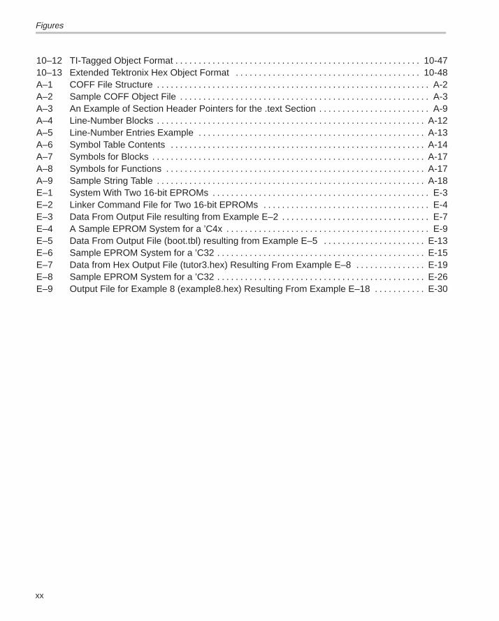
1–1 TMS320 Family Assembly Language Development Flow 1-2. . . . . . . . . . . . . . . . . . . . . . . . . . . 2–1 Partitioning Memory Into Logical Blocks 2-3. . . . . . . . . . . . . . . . . . . . . . . . . . . . . . . . . . . . . . . . . . 2–2 Object Code Generated by Example 2–1 2-11. . . . . . . . . . . . . . . . . . . . . . . . . . . . . . . . . . . . . . . . 2–3 Default Allocation for the Object Code in Figure 2–2 2-13. . . . . . . . . . . . . . . . . . . . . . . . . . . . . . 2–4 Combining Input Sections From Two Files (Default Allocation) 2-14. . . . . . . . . . . . . . . . . . . . . 2–5 Rearranging the Memory Map From Figure 2–3 2-17. . . . . . . . . . . . . . . . . . . . . . . . . . . . . . . . . . 3–1 Assembler Development Flow 3-3. . . . . . . . . . . . . . . . . . . . . . . . . . . . . . . . . . . . . . . . . . . . . . . . . . 4–1 The .align Directive 4-18. . . . . . . . . . . . . . . . . . . . . . . . . . . . . . . . . . . . . . . . . . . . . . . . . . . . . . . . . . . 4–2 The .space Directive 4-62. . . . . . . . . . . . . . . . . . . . . . . . . . . . . . . . . . . . . . . . . . . . . . . . . . . . . . . . . . 4–3 The .usect Directive 4-71. . . . . . . . . . . . . . . . . . . . . . . . . . . . . . . . . . . . . . . . . . . . . . . . . . . . . . . . . . 7–1 Archiver Development Flow 7-2. . . . . . . . . . . . . . . . . . . . . . . . . . . . . . . . . . . . . . . . . . . . . . . . . . . . 8–1 Linker Development Flow 8-3. . . . . . . . . . . . . . . . . . . . . . . . . . . . . . . . . . . . . . . . . . . . . . . . . . . . . . 8–2 Memory Map Defined in Example 8–3 8-26. . . . . . . . . . . . . . . . . . . . . . . . . . . . . . . . . . . . . . . . . . 8–3 Section Allocation Defined by Example 8–4 8-29. . . . . . . . . . . . . . . . . . . . . . . . . . . . . . . . . . . . . . 8–4 Runtime Execution of Example 8–6 8-38. . . . . . . . . . . . . . . . . . . . . . . . . . . . . . . . . . . . . . . . . . . . . 8–5 Memory Allocation for Example 8–7 and Example 8–8 8-40. . . . . . . . . . . . . . . . . . . . . . . . . . . . 8–6 Section Allocation Defined by Example 8–9 8-41. . . . . . . . . . . . . . . . . . . . . . . . . . . . . . . . . . . . . . 8–7 Overlay Pages Defined by Example 8–10 8-43. . . . . . . . . . . . . . . . . . . . . . . . . . . . . . . . . . . . . . . 8–8 RAM Model of Autoinitialization 8-62. . . . . . . . . . . . . . . . . . . . . . . . . . . . . . . . . . . . . . . . . . . . . . . . 8–9 ROM Model of Autoinitialization 8-63. . . . . . . . . . . . . . . . . . . . . . . . . . . . . . . . . . . . . . . . . . . . . . . . 8–10 Linker Command File, demo.cmd 8-65. . . . . . . . . . . . . . . . . . . . . . . . . . . . . . . . . . . . . . . . . . . . . . 8–11 Output Map File, demo.map 8-66. . . . . . . . . . . . . . . . . . . . . . . . . . . . . . . . . . . . . . . . . . . . . . . . . . . 9–1 Absolute Lister Development Flow 9-2. . . . . . . . . . . . . . . . . . . . . . . . . . . . . . . . . . . . . . . . . . . . . . 9–2 module1.lst 9-9. . . . . . . . . . . . . . . . . . . . . . . . . . . . . . . . . . . . . . . . . . . . . . . . . . . . . . . . . . . . . . . . . . . 9–3 module2.lst 9-10. . . . . . . . . . . . . . . . . . . . . . . . . . . . . . . . . . . . . . . . . . . . . . . . . . . . . . . . . . . . . . . . . . 10–1 Hex Conversion Utility Development Flow 10-2. . . . . . . . . . . . . . . . . . . . . . . . . . . . . . . . . . . . . . . 10–2 Hex Conversion Utility Process Flow 10-7. . . . . . . . . . . . . . . . . . . . . . . . . . . . . . . . . . . . . . . . . . . 10–3 Target and Data Widths 10-9. . . . . . . . . . . . . . . . . . . . . . . . . . . . . . . . . . . . . . . . . . . . . . . . . . . . . . . 10–4 Target, Data, and Memory Widths 10-11. . . . . . . . . . . . . . . . . . . . . . . . . . . . . . . . . . . . . . . . . . . . . 10–5 Target, Memory, and ROM Widths 10-13. . . . . . . . . . . . . . . . . . . . . . . . . . . . . . . . . . . . . . . . . . . . . 10–6 ’C3x/’C4x Memory Configuration Example 10-14. . . . . . . . . . . . . . . . . . . . . . . . . . . . . . . . . . . . . . 10–7 Varying the Word Order 10-15. . . . . . . . . . . . . . . . . . . . . . . . . . . . . . . . . . . . . . . . . . . . . . . . . . . . . . 10–8 The infile.out File from Example 10–1 Partitioned Into Eight Output Files 10-20. . . . . . . . . . . 10–9 ASCII-Hex Object Format 10-44. . . . . . . . . . . . . . . . . . . . . . . . . . . . . . . . . . . . . . . . . . . . . . . . . . . . 10–10 Intel Hex Object Format 10-45. . . . . . . . . . . . . . . . . . . . . . . . . . . . . . . . . . . . . . . . . . . . . . . . . . . . . . 10–11 Motorola-S Format 10-46. . . . . . . . . . . . . . . . . . . . . . . . . . . . . . . . . . . . . . . . . . . . . . . . . . . . . . . . . .
Figures
xx
10–12 TI-Tagged Object Format 10-47. . . . . . . . . . . . . . . . . . . . . . . . . . . . . . . . . . . . . . . . . . . . . . . . . . . . . 10–13 Extended Tektronix Hex Object Format 10-48. . . . . . . . . . . . . . . . . . . . . . . . . . . . . . . . . . . . . . . . A–1 COFF File Structure A-2. . . . . . . . . . . . . . . . . . . . . . . . . . . . . . . . . . . . . . . . . . . . . . . . . . . . . . . . . . . A–2 Sample COFF Object File A-3. . . . . . . . . . . . . . . . . . . . . . . . . . . . . . . . . . . . . . . . . . . . . . . . . . . . . . A–3 An Example of Section Header Pointers for the .text Section A-9. . . . . . . . . . . . . . . . . . . . . . . . A–4 Line-Number Blocks A-12. . . . . . . . . . . . . . . . . . . . . . . . . . . . . . . . . . . . . . . . . . . . . . . . . . . . . . . . . . A–5 Line-Number Entries Example A-13. . . . . . . . . . . . . . . . . . . . . . . . . . . . . . . . . . . . . . . . . . . . . . . . . A–6 Symbol Table Contents A-14. . . . . . . . . . . . . . . . . . . . . . . . . . . . . . . . . . . . . . . . . . . . . . . . . . . . . . . A–7 Symbols for Blocks A-17. . . . . . . . . . . . . . . . . . . . . . . . . . . . . . . . . . . . . . . . . . . . . . . . . . . . . . . . . . . A–8 Symbols for Functions A-17. . . . . . . . . . . . . . . . . . . . . . . . . . . . . . . . . . . . . . . . . . . . . . . . . . . . . . . . A–9 Sample String Table A-18. . . . . . . . . . . . . . . . . . . . . . . . . . . . . . . . . . . . . . . . . . . . . . . . . . . . . . . . . . E–1 System With Two 16-bit EPROMs E-3. . . . . . . . . . . . . . . . . . . . . . . . . . . . . . . . . . . . . . . . . . . . . . . E–2 Linker Command File for Two 16-bit EPROMs E-4. . . . . . . . . . . . . . . . . . . . . . . . . . . . . . . . . . . . E–3 Data From Output File resulting from Example E–2 E-7. . . . . . . . . . . . . . . . . . . . . . . . . . . . . . . . E–4 A Sample EPROM System for a ’C4x E-9. . . . . . . . . . . . . . . . . . . . . . . . . . . . . . . . . . . . . . . . . . . . E–5 Data From Output File (boot.tbl) resulting from Example E–5 E-13. . . . . . . . . . . . . . . . . . . . . . E–6 Sample EPROM System for a ’C32 E-15. . . . . . . . . . . . . . . . . . . . . . . . . . . . . . . . . . . . . . . . . . . . . E–7 Data from Hex Output File (tutor3.hex) Resulting From Example E–8 E-19. . . . . . . . . . . . . . . E–8 Sample EPROM System for a ’C32 E-26. . . . . . . . . . . . . . . . . . . . . . . . . . . . . . . . . . . . . . . . . . . . . E–9 Output File for Example 8 (example8.hex) Resulting From Example E–18 E-30. . . . . . . . . . .
Tables
xxi Contents
Tables
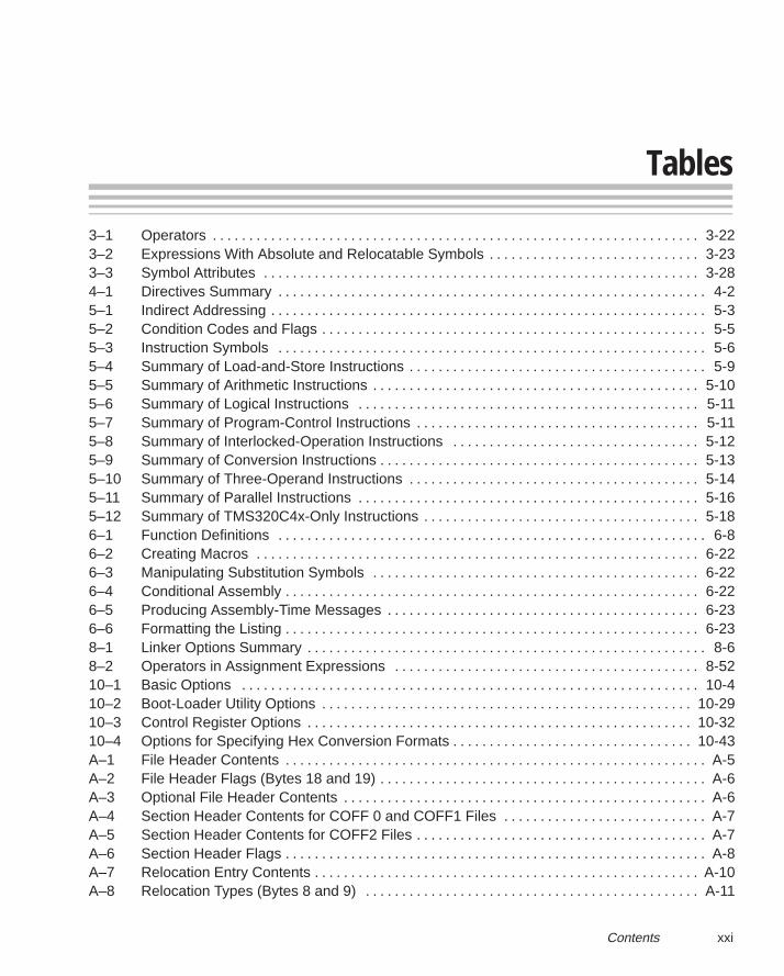
3–1 Operators 3-22. . . . . . . . . . . . . . . . . . . . . . . . . . . . . . . . . . . . . . . . . . . . . . . . . . . . . . . . . . . . . . . . . . . 3–2 Expressions With Absolute and Relocatable Symbols 3-23. . . . . . . . . . . . . . . . . . . . . . . . . . . . . 3–3 Symbol Attributes 3-28. . . . . . . . . . . . . . . . . . . . . . . . . . . . . . . . . . . . . . . . . . . . . . . . . . . . . . . . . . . . 4–1 Directives Summary 4-2. . . . . . . . . . . . . . . . . . . . . . . . . . . . . . . . . . . . . . . . . . . . . . . . . . . . . . . . . . . 5–1 Indirect Addressing 5-3. . . . . . . . . . . . . . . . . . . . . . . . . . . . . . . . . . . . . . . . . . . . . . . . . . . . . . . . . . . . 5–2 Condition Codes and Flags 5-5. . . . . . . . . . . . . . . . . . . . . . . . . . . . . . . . . . . . . . . . . . . . . . . . . . . . . 5–3 Instruction Symbols 5-6. . . . . . . . . . . . . . . . . . . . . . . . . . . . . . . . . . . . . . . . . . . . . . . . . . . . . . . . . . . 5–4 Summary of Load-and-Store Instructions 5-9. . . . . . . . . . . . . . . . . . . . . . . . . . . . . . . . . . . . . . . . . 5–5 Summary of Arithmetic Instructions 5-10. . . . . . . . . . . . . . . . . . . . . . . . . . . . . . . . . . . . . . . . . . . . . 5–6 Summary of Logical Instructions 5-11. . . . . . . . . . . . . . . . . . . . . . . . . . . . . . . . . . . . . . . . . . . . . . . 5–7 Summary of Program-Control Instructions 5-11. . . . . . . . . . . . . . . . . . . . . . . . . . . . . . . . . . . . . . . 5–8 Summary of Interlocked-Operation Instructions 5-12. . . . . . . . . . . . . . . . . . . . . . . . . . . . . . . . . . 5–9 Summary of Conversion Instructions 5-13. . . . . . . . . . . . . . . . . . . . . . . . . . . . . . . . . . . . . . . . . . . . 5–10 Summary of Three-Operand Instructions 5-14. . . . . . . . . . . . . . . . . . . . . . . . . . . . . . . . . . . . . . . . 5–11 Summary of Parallel Instructions 5-16. . . . . . . . . . . . . . . . . . . . . . . . . . . . . . . . . . . . . . . . . . . . . . . 5–12 Summary of TMS320C4x-Only Instructions 5-18. . . . . . . . . . . . . . . . . . . . . . . . . . . . . . . . . . . . . . 6–1 Function Definitions 6-8. . . . . . . . . . . . . . . . . . . . . . . . . . . . . . . . . . . . . . . . . . . . . . . . . . . . . . . . . . . 6–2 Creating Macros 6-22. . . . . . . . . . . . . . . . . . . . . . . . . . . . . . . . . . . . . . . . . . . . . . . . . . . . . . . . . . . . . 6–3 Manipulating Substitution Symbols 6-22. . . . . . . . . . . . . . . . . . . . . . . . . . . . . . . . . . . . . . . . . . . . . 6–4 Conditional Assembly 6-22. . . . . . . . . . . . . . . . . . . . . . . . . . . . . . . . . . . . . . . . . . . . . . . . . . . . . . . . . 6–5 Producing Assembly-Time Messages 6-23. . . . . . . . . . . . . . . . . . . . . . . . . . . . . . . . . . . . . . . . . . . 6–6 Formatting the Listing 6-23. . . . . . . . . . . . . . . . . . . . . . . . . . . . . . . . . . . . . . . . . . . . . . . . . . . . . . . . . 8–1 Linker Options Summary 8-6. . . . . . . . . . . . . . . . . . . . . . . . . . . . . . . . . . . . . . . . . . . . . . . . . . . . . . . 8–2 Operators in Assignment Expressions 8-52. . . . . . . . . . . . . . . . . . . . . . . . . . . . . . . . . . . . . . . . . . 10–1 Basic Options 10-4. . . . . . . . . . . . . . . . . . . . . . . . . . . . . . . . . . . . . . . . . . . . . . . . . . . . . . . . . . . . . . . 10–2 Boot-Loader Utility Options 10-29. . . . . . . . . . . . . . . . . . . . . . . . . . . . . . . . . . . . . . . . . . . . . . . . . . . 10–3 Control Register Options 10-32. . . . . . . . . . . . . . . . . . . . . . . . . . . . . . . . . . . . . . . . . . . . . . . . . . . . . 10–4 Options for Specifying Hex Conversion Formats 10-43. . . . . . . . . . . . . . . . . . . . . . . . . . . . . . . . . A–1 File Header Contents A-5. . . . . . . . . . . . . . . . . . . . . . . . . . . . . . . . . . . . . . . . . . . . . . . . . . . . . . . . . . A–2 File Header Flags (Bytes 18 and 19) A-6. . . . . . . . . . . . . . . . . . . . . . . . . . . . . . . . . . . . . . . . . . . . . A–3 Optional File Header Contents A-6. . . . . . . . . . . . . . . . . . . . . . . . . . . . . . . . . . . . . . . . . . . . . . . . . . A–4 Section Header Contents for COFF 0 and COFF1 Files A-7. . . . . . . . . . . . . . . . . . . . . . . . . . . . A–5 Section Header Contents for COFF2 Files A-7. . . . . . . . . . . . . . . . . . . . . . . . . . . . . . . . . . . . . . . . A–6 Section Header Flags A-8. . . . . . . . . . . . . . . . . . . . . . . . . . . . . . . . . . . . . . . . . . . . . . . . . . . . . . . . . . A–7 Relocation Entry Contents A-10. . . . . . . . . . . . . . . . . . . . . . . . . . . . . . . . . . . . . . . . . . . . . . . . . . . . . A–8 Relocation Types (Bytes 8 and 9) A-11. . . . . . . . . . . . . . . . . . . . . . . . . . . . . . . . . . . . . . . . . . . . . .
Tables
xxii
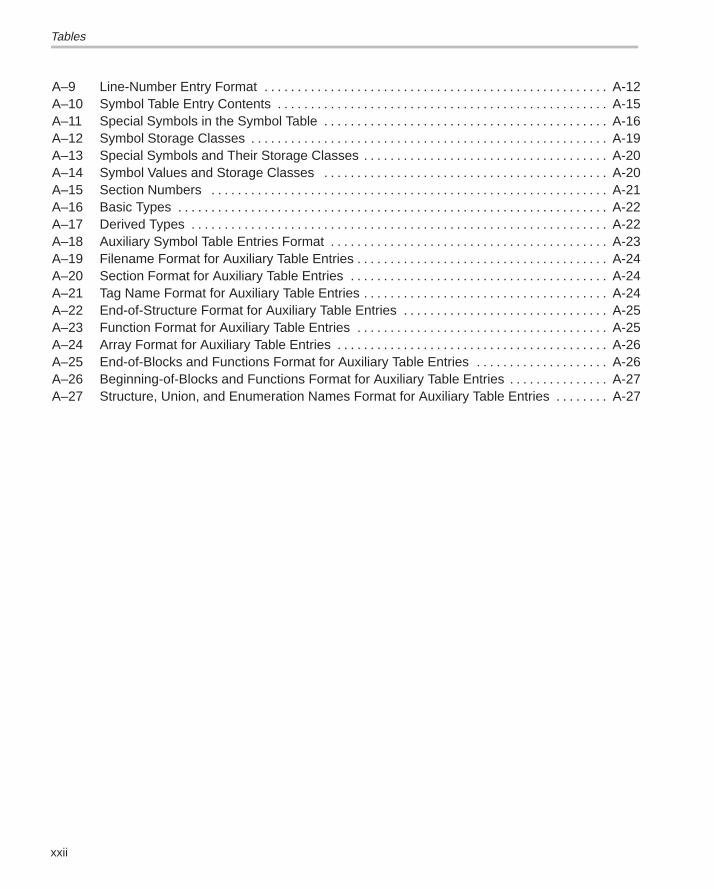
A–9 Line-Number Entry Format A-12. . . . . . . . . . . . . . . . . . . . . . . . . . . . . . . . . . . . . . . . . . . . . . . . . . . . A–10 Symbol Table Entry Contents A-15. . . . . . . . . . . . . . . . . . . . . . . . . . . . . . . . . . . . . . . . . . . . . . . . . . A–11 Special Symbols in the Symbol Table A-16. . . . . . . . . . . . . . . . . . . . . . . . . . . . . . . . . . . . . . . . . . . A–12 Symbol Storage Classes A-19. . . . . . . . . . . . . . . . . . . . . . . . . . . . . . . . . . . . . . . . . . . . . . . . . . . . . . A–13 Special Symbols and Their Storage Classes A-20. . . . . . . . . . . . . . . . . . . . . . . . . . . . . . . . . . . . . A–14 Symbol Values and Storage Classes A-20. . . . . . . . . . . . . . . . . . . . . . . . . . . . . . . . . . . . . . . . . . . A–15 Section Numbers A-21. . . . . . . . . . . . . . . . . . . . . . . . . . . . . . . . . . . . . . . . . . . . . . . . . . . . . . . . . . . . A–16 Basic Types A-22. . . . . . . . . . . . . . . . . . . . . . . . . . . . . . . . . . . . . . . . . . . . . . . . . . . . . . . . . . . . . . . . . A–17 Derived Types A-22. . . . . . . . . . . . . . . . . . . . . . . . . . . . . . . . . . . . . . . . . . . . . . . . . . . . . . . . . . . . . . . A–18 Auxiliary Symbol Table Entries Format A-23. . . . . . . . . . . . . . . . . . . . . . . . . . . . . . . . . . . . . . . . . . A–19 Filename Format for Auxiliary Table Entries A-24. . . . . . . . . . . . . . . . . . . . . . . . . . . . . . . . . . . . . . A–20 Section Format for Auxiliary Table Entries A-24. . . . . . . . . . . . . . . . . . . . . . . . . . . . . . . . . . . . . . . A–21 Tag Name Format for Auxiliary Table Entries A-24. . . . . . . . . . . . . . . . . . . . . . . . . . . . . . . . . . . . . A–22 End-of-Structure Format for Auxiliary Table Entries A-25. . . . . . . . . . . . . . . . . . . . . . . . . . . . . . . A–23 Function Format for Auxiliary Table Entries A-25. . . . . . . . . . . . . . . . . . . . . . . . . . . . . . . . . . . . . . A–24 Array Format for Auxiliary Table Entries A-26. . . . . . . . . . . . . . . . . . . . . . . . . . . . . . . . . . . . . . . . . A–25 End-of-Blocks and Functions Format for Auxiliary Table Entries A-26. . . . . . . . . . . . . . . . . . . . A–26 Beginning-of-Blocks and Functions Format for Auxiliary Table Entries A-27. . . . . . . . . . . . . . . A–27 Structure, Union, and Enumeration Names Format for Auxiliary Table Entries A-27. . . . . . . .
Examples
xxiii Contents
Examples
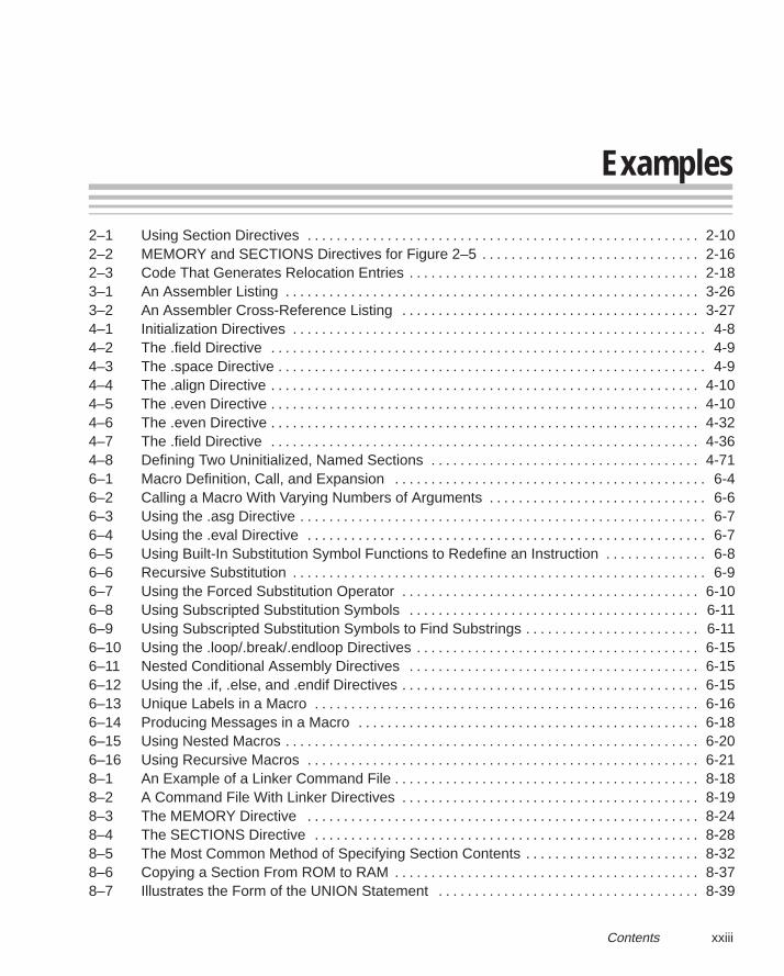
2–1 Using Section Directives 2-10. . . . . . . . . . . . . . . . . . . . . . . . . . . . . . . . . . . . . . . . . . . . . . . . . . . . . . 2–2 MEMORY and SECTIONS Directives for Figure 2–5 2-16. . . . . . . . . . . . . . . . . . . . . . . . . . . . . . 2–3 Code That Generates Relocation Entries 2-18. . . . . . . . . . . . . . . . . . . . . . . . . . . . . . . . . . . . . . . . 3–1 An Assembler Listing 3-26. . . . . . . . . . . . . . . . . . . . . . . . . . . . . . . . . . . . . . . . . . . . . . . . . . . . . . . . . 3–2 An Assembler Cross-Reference Listing 3-27. . . . . . . . . . . . . . . . . . . . . . . . . . . . . . . . . . . . . . . . . 4–1 Initialization Directives 4-8. . . . . . . . . . . . . . . . . . . . . . . . . . . . . . . . . . . . . . . . . . . . . . . . . . . . . . . . . 4–2 The .field Directive 4-9. . . . . . . . . . . . . . . . . . . . . . . . . . . . . . . . . . . . . . . . . . . . . . . . . . . . . . . . . . . . 4–3 The .space Directive 4-9. . . . . . . . . . . . . . . . . . . . . . . . . . . . . . . . . . . . . . . . . . . . . . . . . . . . . . . . . . . 4–4 The .align Directive 4-10. . . . . . . . . . . . . . . . . . . . . . . . . . . . . . . . . . . . . . . . . . . . . . . . . . . . . . . . . . . 4–5 The .even Directive 4-10. . . . . . . . . . . . . . . . . . . . . . . . . . . . . . . . . . . . . . . . . . . . . . . . . . . . . . . . . . . 4–6 The .even Directive 4-32. . . . . . . . . . . . . . . . . . . . . . . . . . . . . . . . . . . . . . . . . . . . . . . . . . . . . . . . . . . 4–7 The .field Directive 4-36. . . . . . . . . . . . . . . . . . . . . . . . . . . . . . . . . . . . . . . . . . . . . . . . . . . . . . . . . . . 4–8 Defining Two Uninitialized, Named Sections 4-71. . . . . . . . . . . . . . . . . . . . . . . . . . . . . . . . . . . . . 6–1 Macro Definition, Call, and Expansion 6-4. . . . . . . . . . . . . . . . . . . . . . . . . . . . . . . . . . . . . . . . . . . 6–2 Calling a Macro With Varying Numbers of Arguments 6-6. . . . . . . . . . . . . . . . . . . . . . . . . . . . . . 6–3 Using the .asg Directive 6-7. . . . . . . . . . . . . . . . . . . . . . . . . . . . . . . . . . . . . . . . . . . . . . . . . . . . . . . . 6–4 Using the .eval Directive 6-7. . . . . . . . . . . . . . . . . . . . . . . . . . . . . . . . . . . . . . . . . . . . . . . . . . . . . . . 6–5 Using Built-In Substitution Symbol Functions to Redefine an Instruction 6-8. . . . . . . . . . . . . . 6–6 Recursive Substitution 6-9. . . . . . . . . . . . . . . . . . . . . . . . . . . . . . . . . . . . . . . . . . . . . . . . . . . . . . . . . 6–7 Using the Forced Substitution Operator 6-10. . . . . . . . . . . . . . . . . . . . . . . . . . . . . . . . . . . . . . . . . 6–8 Using Subscripted Substitution Symbols 6-11. . . . . . . . . . . . . . . . . . . . . . . . . . . . . . . . . . . . . . . . 6–9 Using Subscripted Substitution Symbols to Find Substrings 6-11. . . . . . . . . . . . . . . . . . . . . . . . 6–10 Using the .loop/.break/.endloop Directives 6-15. . . . . . . . . . . . . . . . . . . . . . . . . . . . . . . . . . . . . . . 6–11 Nested Conditional Assembly Directives 6-15. . . . . . . . . . . . . . . . . . . . . . . . . . . . . . . . . . . . . . . . 6–12 Using the .if, .else, and .endif Directives 6-15. . . . . . . . . . . . . . . . . . . . . . . . . . . . . . . . . . . . . . . . . 6–13 Unique Labels in a Macro 6-16. . . . . . . . . . . . . . . . . . . . . . . . . . . . . . . . . . . . . . . . . . . . . . . . . . . . . 6–14 Producing Messages in a Macro 6-18. . . . . . . . . . . . . . . . . . . . . . . . . . . . . . . . . . . . . . . . . . . . . . . 6–15 Using Nested Macros 6-20. . . . . . . . . . . . . . . . . . . . . . . . . . . . . . . . . . . . . . . . . . . . . . . . . . . . . . . . . 6–16 Using Recursive Macros 6-21. . . . . . . . . . . . . . . . . . . . . . . . . . . . . . . . . . . . . . . . . . . . . . . . . . . . . . 8–1 An Example of a Linker Command File 8-18. . . . . . . . . . . . . . . . . . . . . . . . . . . . . . . . . . . . . . . . . . 8–2 A Command File With Linker Directives 8-19. . . . . . . . . . . . . . . . . . . . . . . . . . . . . . . . . . . . . . . . . 8–3 The MEMORY Directive 8-24. . . . . . . . . . . . . . . . . . . . . . . . . . . . . . . . . . . . . . . . . . . . . . . . . . . . . . 8–4 The SECTIONS Directive 8-28. . . . . . . . . . . . . . . . . . . . . . . . . . . . . . . . . . . . . . . . . . . . . . . . . . . . . 8–5 The Most Common Method of Specifying Section Contents 8-32. . . . . . . . . . . . . . . . . . . . . . . . 8–6 Copying a Section From ROM to RAM 8-37. . . . . . . . . . . . . . . . . . . . . . . . . . . . . . . . . . . . . . . . . . 8–7 Illustrates the Form of the UNION Statement 8-39. . . . . . . . . . . . . . . . . . . . . . . . . . . . . . . . . . . .
Examples
xxiv
8–8 Illustrates Separate Load Addresses for UNION Sections 8-39. . . . . . . . . . . . . . . . . . . . . . . . . 8–9 Using the GROUP Directive 8-41. . . . . . . . . . . . . . . . . . . . . . . . . . . . . . . . . . . . . . . . . . . . . . . . . . . 8–10 Overlay Pages 8-43. . . . . . . . . . . . . . . . . . . . . . . . . . . . . . . . . . . . . . . . . . . . . . . . . . . . . . . . . . . . . . . 8–11 SECTIONS Directive Definition for Figure 8–7 8-44. . . . . . . . . . . . . . . . . . . . . . . . . . . . . . . . . . . 10–1 A ROMS Directive Example 10-19. . . . . . . . . . . . . . . . . . . . . . . . . . . . . . . . . . . . . . . . . . . . . . . . . . 10–2 Map File Output from Example 10–1 Showing Memory Ranges 10-21. . . . . . . . . . . . . . . . . . . 10–3 Using the TMS320C31 Boot Loader 10-33. . . . . . . . . . . . . . . . . . . . . . . . . . . . . . . . . . . . . . . . . . . 10–4 Using the TMS320C32 Boot Loader 10-36. . . . . . . . . . . . . . . . . . . . . . . . . . . . . . . . . . . . . . . . . . . 10–5 Using the ’C4x Boot Loader 10-38. . . . . . . . . . . . . . . . . . . . . . . . . . . . . . . . . . . . . . . . . . . . . . . . . . 10–6 Hex Command File For Hole Avoidance 10-42. . . . . . . . . . . . . . . . . . . . . . . . . . . . . . . . . . . . . . . . E–1 Sample ASM Code E-2. . . . . . . . . . . . . . . . . . . . . . . . . . . . . . . . . . . . . . . . . . . . . . . . . . . . . . . . . . . . E–2 Command File for Two 16-bit EPROMs E-6. . . . . . . . . . . . . . . . . . . . . . . . . . . . . . . . . . . . . . . . . . E–3 Hex Conversion Map File Resulting From Example E–2 E-8. . . . . . . . . . . . . . . . . . . . . . . . . . . . E–4 Linker Command File for Booting From the ’C4x COMM Port E-10. . . . . . . . . . . . . . . . . . . . . . E–5 Command File for Booting From the ’C4x COMM Port E-12. . . . . . . . . . . . . . . . . . . . . . . . . . . . E–6 Map File Resulting From Example E–5 E-14. . . . . . . . . . . . . . . . . . . . . . . . . . . . . . . . . . . . . . . . . . E–7 Linker Command File for a ’C32 E-16. . . . . . . . . . . . . . . . . . . . . . . . . . . . . . . . . . . . . . . . . . . . . . . . E–8 Sample Hex Command File for a ’C32 E-18. . . . . . . . . . . . . . . . . . . . . . . . . . . . . . . . . . . . . . . . . . E–9 Code for Four 8-Bit EPROM Files E-20. . . . . . . . . . . . . . . . . . . . . . . . . . . . . . . . . . . . . . . . . . . . . . E–10 Linker Command File for Avoiding Holes: Method One E-21. . . . . . . . . . . . . . . . . . . . . . . . . . . . E–11 Hex Conversion Utility Command File for Avoiding Holes: Method One E-22. . . . . . . . . . . . . . E–12 Linker Command File for Avoiding Holes: Method Two E-22. . . . . . . . . . . . . . . . . . . . . . . . . . . . E–13 Hex Conversion Utility Command File for Avoiding Holes: Method Two E-22. . . . . . . . . . . . . . E–14 Command File for a ’C31 SERIAL Port Boot Load E-23. . . . . . . . . . . . . . . . . . . . . . . . . . . . . . . . E–15 Linker Command File for Dealing With Three Different Addresses E-24. . . . . . . . . . . . . . . . . . E–16 Hex Command File for Dealing With Three Different Addresses E-25. . . . . . . . . . . . . . . . . . . . E–17 Linker Command File for a ’C32 E-27. . . . . . . . . . . . . . . . . . . . . . . . . . . . . . . . . . . . . . . . . . . . . . . . E–18 Hex Command File For a ’C32 Boot Table E-28. . . . . . . . . . . . . . . . . . . . . . . . . . . . . . . . . . . . . . .
1-1Introduction
Introduction
The TMS320C3x/C4x DSPs are supported by the following assemblylanguage tools:
� Assembler� Archiver� Linker� Hex conversion utility
This chapter shows how these tools fit into the general software tools develop-ment flow and gives a brief description of each tool. For convenience, it alsosummarizes the C compiler and debugging tools; however, the compiler anddebugger are not shipped with the assembly language tools. For detailedinformation on the compiler and debugger and for complete descriptions of theTMS320C3x/C4x devices, refer to books listed in Related DocumentationFrom Texas Instruments, page vi.
The assembly language tools create and use object files in common object fileformat (COFF) to facilitate modular programming. Object files contain sepa-rate blocks (called sections) of code and data that you can load into TMS320memory spaces. You can program the TMS320 devices more efficiently if youhave a basic understanding of COFF. Chapter 2, Introduction to CommonObject File Format, discusses this object format in detail.
Topic Page
1.1 Software Development Tools Overview 1-2. . . . . . . . . . . . . . . . . . . . . . . . .
1.2 Tools Descriptions 1-3. . . . . . . . . . . . . . . . . . . . . . . . . . . . . . . . . . . . . . . . . . . .
Chapter 1
Software Development Tools Overview
1-2
1.1 Software Development Tools Overview
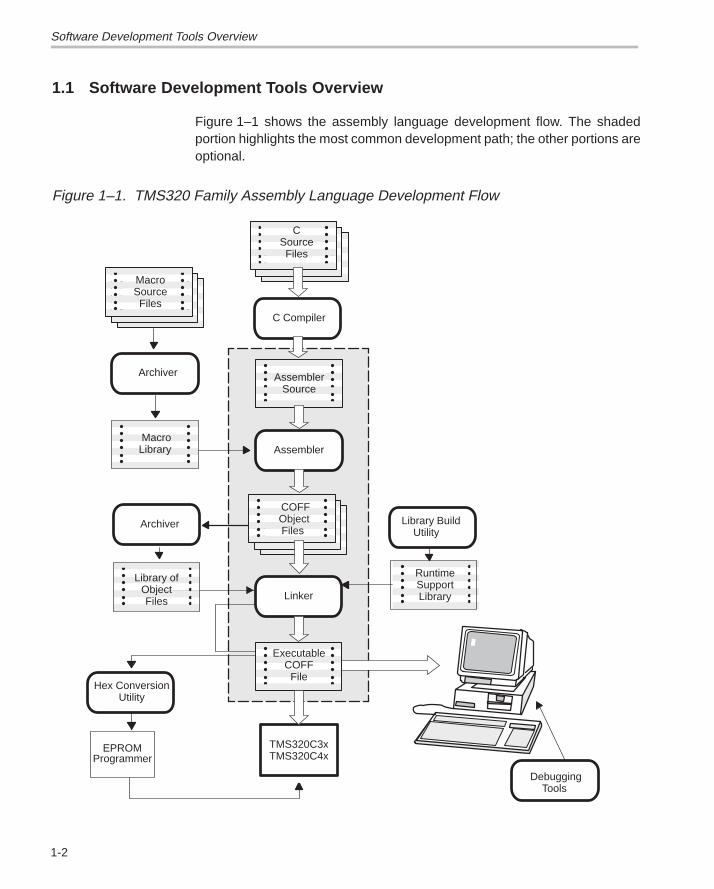
Figure 1–1 shows the assembly language development flow. The shadedportion highlights the most common development path; the other portions areoptional.
Figure 1–1. TMS320 Family Assembly Language Development Flow
Assembler
Linker
C Compiler
Archiver
MacroLibrary
MacroSourceFiles
Archiver
Hex ConversionUtility
EPROMProgrammer
Debugging Tools
CSourceFiles
AssemblerSource
COFF ObjectFiles
TMS320C3xTMS320C4x
ExecutableCOFF
File
RuntimeSupportLibrary
Library Build Utility
Library ofObjectFiles
Tools Descriptions
1-3Introduction
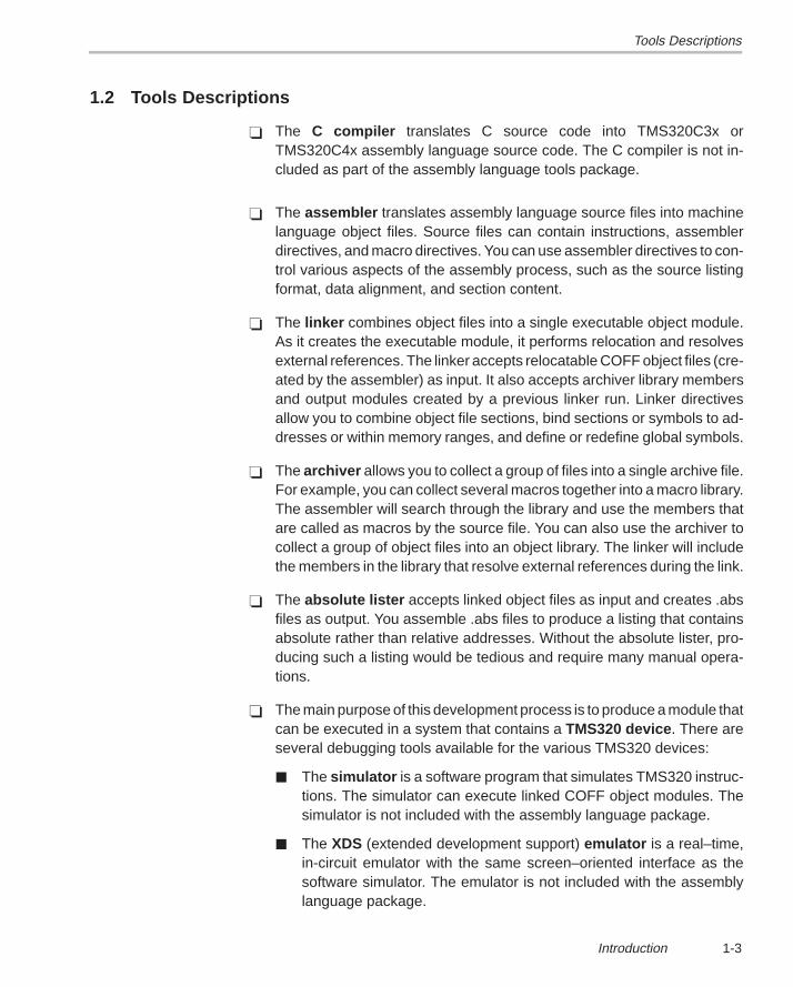
1.2 Tools Descriptions
� The C compiler translates C source code into TMS320C3x orTMS320C4x assembly language source code. The C compiler is not in-cluded as part of the assembly language tools package.
� The assembler translates assembly language source files into machinelanguage object files. Source files can contain instructions, assemblerdirectives, and macro directives. You can use assembler directives to con-trol various aspects of the assembly process, such as the source listingformat, data alignment, and section content.
� The linker combines object files into a single executable object module.As it creates the executable module, it performs relocation and resolvesexternal references. The linker accepts relocatable COFF object files (cre-ated by the assembler) as input. It also accepts archiver library membersand output modules created by a previous linker run. Linker directivesallow you to combine object file sections, bind sections or symbols to ad-dresses or within memory ranges, and define or redefine global symbols.
� The archiver allows you to collect a group of files into a single archive file.For example, you can collect several macros together into a macro library.The assembler will search through the library and use the members thatare called as macros by the source file. You can also use the archiver tocollect a group of object files into an object library. The linker will includethe members in the library that resolve external references during the link.
� The absolute lister accepts linked object files as input and creates .absfiles as output. You assemble .abs files to produce a listing that containsabsolute rather than relative addresses. Without the absolute lister, pro-ducing such a listing would be tedious and require many manual opera-tions.
� The main purpose of this development process is to produce a module thatcan be executed in a system that contains a TMS320 device . There areseveral debugging tools available for the various TMS320 devices:
� The simulator is a software program that simulates TMS320 instruc-tions. The simulator can execute linked COFF object modules. Thesimulator is not included with the assembly language package.
� The XDS (extended development support) emulator is a real–time,in-circuit emulator with the same screen–oriented interface as thesoftware simulator. The emulator is not included with the assemblylanguage package.
Tools Descriptions
1-4
� The evaluation module (EVM) is a low-cost development board thatprovides full-speed in-circuit emulation and hardware debugging. TheEVM is available now for the TMS320C3x devices and will be avail-able soon for the TMS320C4x devices.
� The C source debugger is a software interface to the simulator, emu-lator, and EVM.
� The TMS320C3x/4x devices accept COFF files as input, but mostEPROM programmers do not. The hex conversion utility converts aCOFF object file into TI–tagged, Intel, Motorola S1/S2/S3, or Tektronixobject format. The converted file can be downloaded to an EPROMprogrammer.
2-1Introduction to Common Object File Format
Introduction to Common Object File Format
The assembler and linker create object files that can be executed by aTMS320C3x/C4x device. The format that these object files are in is calledcommon object file format, or COFF.
COFF makes modular programming easier because it encourages you tothink in terms of blocks of code and data when you write an assembly languageprogram. These blocks are known as sections . Both the assembler and thelinker provide directives that allow you to create and manipulate sections.
In addition to this chapter, Appendix A details COFF object file structure. Forexample, it describes the fields in a file header and the structure of a symboltable entry. Appendix A is useful mainly for those of you who are interested inthe internal format of object files.
Topic Page
2.1 COFF File Types 2-2. . . . . . . . . . . . . . . . . . . . . . . . . . . . . . . . . . . . . . . . . . . . . .
2.2 Sections 2-2. . . . . . . . . . . . . . . . . . . . . . . . . . . . . . . . . . . . . . . . . . . . . . . . . . . . .
2.3 How the Assembler Handles Sections 2-4. . . . . . . . . . . . . . . . . . . . . . . . . .
2.4 How the Linker Handles Sections 2-12. . . . . . . . . . . . . . . . . . . . . . . . . . . . .
2.5 Relocation 2-18. . . . . . . . . . . . . . . . . . . . . . . . . . . . . . . . . . . . . . . . . . . . . . . . . . .
2.6 Runtime Relocation 2-20. . . . . . . . . . . . . . . . . . . . . . . . . . . . . . . . . . . . . . . . . .
2.7 Loading a Program 2-21. . . . . . . . . . . . . . . . . . . . . . . . . . . . . . . . . . . . . . . . . . .
2.8 Symbols in a COFF File 2-22. . . . . . . . . . . . . . . . . . . . . . . . . . . . . . . . . . . . . . .
Chapter 2
COFF File Types
2-2
2.1 COFF File Types
The following types of COFF files exist:
� COFF0� COFF1� COFF2
Each COFF file type has a different header format. The data portions of theCOFF files are identical. For details about the COFF file structure, seeAppendix A, Common Object File Format.
The TMS320C3x/C4x assembler and C compiler create COFF2 files. Thelinker can read and write all types of COFF files. By default, the linker createsCOFF2 files. Use the –v linker option to specify a different format. The linkersupports COFF0 and COFF1 files for older versions of the assembler and Ccompiler only.
2.2 Sections
The smallest unit of an object file is called a section . A section is a block ofcode or data that will ultimately occupy contiguous space in theTMS320C3x/C4x memory map. Each section of an object file is separate anddistinct from the other sections. COFF object files always contain three defaultsections:
.text usually contains executable code.
.data usually contains initialized data.
.bss usually reserves space for uninitialized variables.
In addition, the assembler and linker allow you to create, name, and linknamed sections that are used similarly to the .data, .text, and .bss sections.
It is important to note that there are two basic types of sections:
Initialized sections contain data or code. The .text and .data sectionsare initialized; named sections created with the.sect and .asect assembler directives are also in-itialized.
Uninitialized sections reserve space in the memory map for uninitializeddata. The .bss section is uninitialized; named sec-tions created with the .usect assembler directiveare also uninitialized.
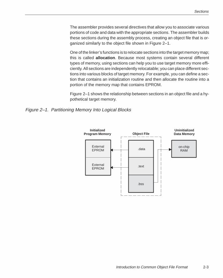
Sections
2-3Introduction to Common Object File Format
The assembler provides several directives that allow you to associate variousportions of code and data with the appropriate sections. The assembler buildsthese sections during the assembly process, creating an object file that is or-ganized similarly to the object file shown in Figure 2–1.
One of the linker’s functions is to relocate sections into the target memory map;this is called allocation . Because most systems contain several differenttypes of memory, using sections can help you to use target memory more effi-ciently. All sections are independently relocatable; you can place different sec-tions into various blocks of target memory. For example, you can define a sec-tion that contains an initialization routine and then allocate the routine into aportion of the memory map that contains EPROM.
Figure 2–1 shows the relationship between sections in an object file and a hy-pothetical target memory.
Figure 2–1. Partitioning Memory Into Logical Blocks
.text
.data
.bss
Object File
ExternalEPROM
ExternalEPROM
on-chipRAM
InitializedProgram Memory
UninitializedData Memory
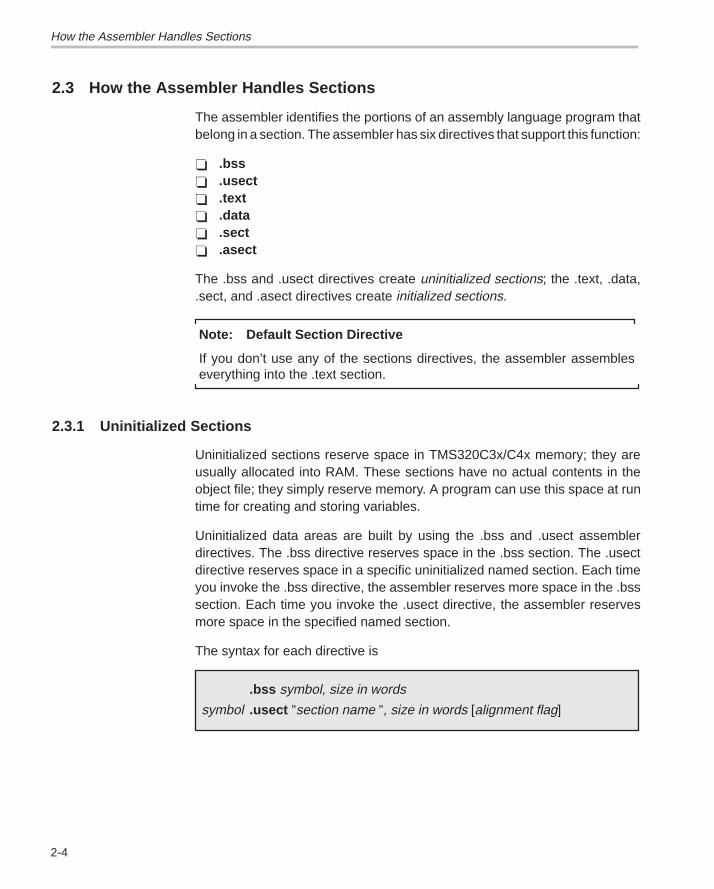
How the Assembler Handles Sections
2-4
2.3 How the Assembler Handles Sections
The assembler identifies the portions of an assembly language program thatbelong in a section. The assembler has six directives that support this function:
� .bss� .usect� .text� .data� .sect� .asect
The .bss and .usect directives create uninitialized sections; the .text, .data,.sect, and .asect directives create initialized sections.
Note: Default Section Directive
If you don’t use any of the sections directives, the assembler assembleseverything into the .text section.
2.3.1 Uninitialized Sections
Uninitialized sections reserve space in TMS320C3x/C4x memory; they areusually allocated into RAM. These sections have no actual contents in theobject file; they simply reserve memory. A program can use this space at runtime for creating and storing variables.
Uninitialized data areas are built by using the .bss and .usect assemblerdirectives. The .bss directive reserves space in the .bss section. The .usectdirective reserves space in a specific uninitialized named section. Each timeyou invoke the .bss directive, the assembler reserves more space in the .bsssection. Each time you invoke the .usect directive, the assembler reservesmore space in the specified named section.
The syntax for each directive is
.bss symbol, size in words
symbol .usect ”section name ”, size in words [alignment flag]
How the Assembler Handles Sections
2-5Introduction to Common Object File Format
symbol points to the first byte reserved by this invocation of the .bssor .usect directive. The symbol corresponds to the name ofthe variable for which you’re reserving space. It can be ref-erenced by any other section and can also be declared asa global symbol (with the .global assembler directive).
size is an absolute expression. The .bss directive reserves sizewords in the .bss section; the .usect directive reserves sizewords in section name. There is no default size for the .bsssection.
section name tells the assembler which named section to reserve spacein. For more information about named sections, refer tosubsection 2.3.3.
blocking flag is an optional parameter. If present and nonzero, the flagmeans that this section will be blocked. Blocking is an ad-dress alignment mechanism similar to alignment, butweaker. It means a section is guaranteed not to cross apage boundary (128 words) if it is smaller than a page, andto start on a page boundary if it is larger than a page. Thisblocking applies to the section, not to the object declaredwith this instance of the .usect directive.
alignment flag is an optional parameter. If present and nonzero, the sec-tion will be aligned to a long word boundary.
The .text, .data, .sect, and .asect directives tell the assembler to stopassembling into the current section and begin assembling into the indicatedsection. The .bss and .usect directives, however, do not end the currentsection and begin a new one; they simply escape from the current sectiontemporarily. The .bss and .usect directives can appear anywhere in an initial-ized section without affecting the contents of the initialized section.
2.3.2 Initialized Sections
Initialized sections contain executable code or initialized data. The contentsof these sections are stored in the object file and placed in TMS320C3x/C4xmemory when the program is loaded. Each initialized section is separatelyrelocatable and may reference symbols that are defined in other sections. Thelinker automatically resolves these section-relative references.
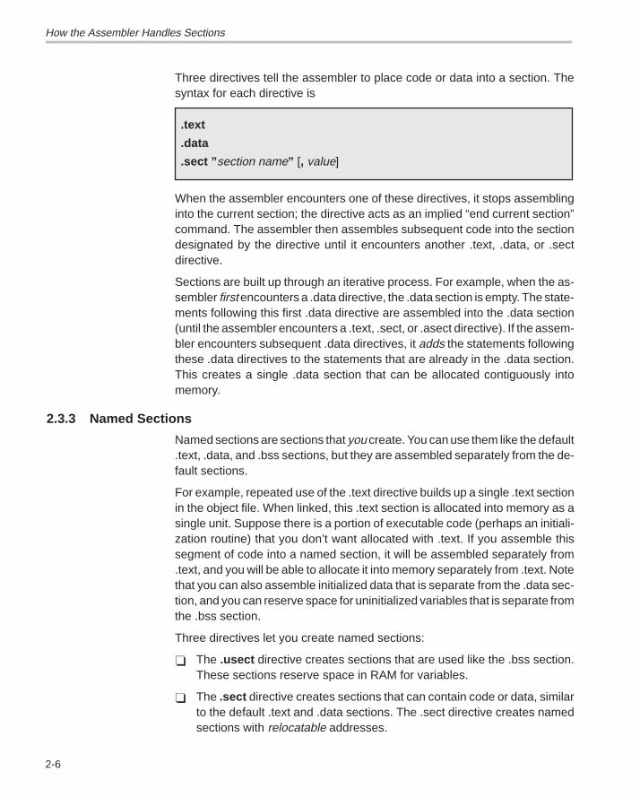
How the Assembler Handles Sections
2-6
Three directives tell the assembler to place code or data into a section. Thesyntax for each directive is
.text
.data
.sect ” section name” [, value]
When the assembler encounters one of these directives, it stops assemblinginto the current section; the directive acts as an implied “end current section”command. The assembler then assembles subsequent code into the sectiondesignated by the directive until it encounters another .text, .data, or .sectdirective.
Sections are built up through an iterative process. For example, when the as-sembler first encounters a .data directive, the .data section is empty. The state-ments following this first .data directive are assembled into the .data section(until the assembler encounters a .text, .sect, or .asect directive). If the assem-bler encounters subsequent .data directives, it adds the statements followingthese .data directives to the statements that are already in the .data section.This creates a single .data section that can be allocated contiguously intomemory.
2.3.3 Named Sections
Named sections are sections that you create. You can use them like the default.text, .data, and .bss sections, but they are assembled separately from the de-fault sections.
For example, repeated use of the .text directive builds up a single .text sectionin the object file. When linked, this .text section is allocated into memory as asingle unit. Suppose there is a portion of executable code (perhaps an initiali-zation routine) that you don’t want allocated with .text. If you assemble thissegment of code into a named section, it will be assembled separately from.text, and you will be able to allocate it into memory separately from .text. Notethat you can also assemble initialized data that is separate from the .data sec-tion, and you can reserve space for uninitialized variables that is separate fromthe .bss section.
Three directives let you create named sections:
� The .usect directive creates sections that are used like the .bss section.These sections reserve space in RAM for variables.
� The .sect directive creates sections that can contain code or data, similarto the default .text and .data sections. The .sect directive creates namedsections with relocatable addresses.
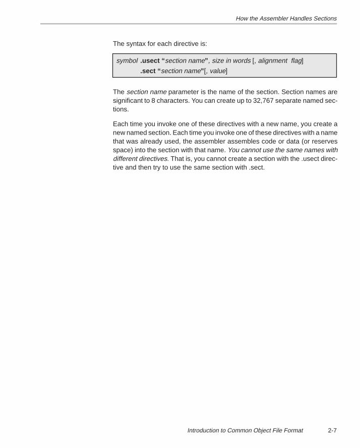
How the Assembler Handles Sections
2-7Introduction to Common Object File Format
The syntax for each directive is:
symbol .usect “ section name” , size in words [, alignment flag]
.sect “ section name” [, value]
The section name parameter is the name of the section. Section names aresignificant to 8 characters. You can create up to 32,767 separate named sec-tions.
Each time you invoke one of these directives with a new name, you create anew named section. Each time you invoke one of these directives with a namethat was already used, the assembler assembles code or data (or reservesspace) into the section with that name. You cannot use the same names withdifferent directives. That is, you cannot create a section with the .usect direc-tive and then try to use the same section with .sect.
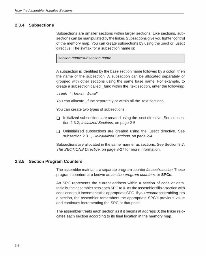
How the Assembler Handles Sections
2-8
2.3.4 Subsections
Subsections are smaller sections within larger sections. Like sections, sub-sections can be manipulated by the linker. Subsections give you tighter controlof the memory map. You can create subsections by using the .sect or .usectdirective. The syntax for a subsection name is:
section name:subsection name
A subsection is identified by the base section name followed by a colon, thenthe name of the subsection. A subsection can be allocated separately orgrouped with other sections using the same base name. For example, tocreate a subsection called _func within the .text section, enter the following:
.sect ”.text:_func”
You can allocate _func separately or within all the .text sections.
You can create two types of subsections:
� Initialized subsections are created using the .sect directive. See subsec-tion 2.3.2, Initialized Sections, on page 2-5.
� Uninitialized subsections are created using the .usect directive. Seesubsection 2.3.1, Uninitialized Sections, on page 2-4.
Subsections are allocated in the same manner as sections. See Section 8.7,The SECTIONS Directive, on page 8-27 for more information.
2.3.5 Section Program Counters
The assembler maintains a separate program counter for each section. Theseprogram counters are known as section program counters, or SPCs.
An SPC represents the current address within a section of code or data.Initially, the assembler sets each SPC to 0. As the assembler fills a section withcode or data, it increments the appropriate SPC. If you resume assembling intoa section, the assembler remembers the appropriate SPC’s previous valueand continues incrementing the SPC at that point.
The assembler treats each section as if it begins at address 0; the linker relo-cates each section according to its final location in the memory map.
How the Assembler Handles Sections
2-9Introduction to Common Object File Format
2.3.6 An Example That Uses Sections Directives
Figure 2–1 shows how you can build COFF sections incrementally, using thesections directives to swap back and forth between the different sections. Youcan use sections directives to
� Begin assembling into a section for the first time, or
� Continue assembling into a section that already contains code. In thiscase, the assembler simply appends the new code to the code that is al-ready in the section.
The format in this example is a listing file. Example 2–1 shows how the SPCsare modified during assembly. A line in a listing file has four fields:
Field 1 contains the source code line counter.
Field 2 contains the section program counter.
Field 3 contains the object code.
Field 4 contains the original source statement.
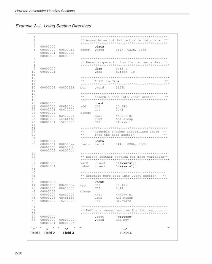
How the Assembler Handles Sections
2-10
Example 2–1. Using Section Directives
Field 2Field 1 Field 3 Field 4
1 **********************************************2 ** Assemble an initialized table into data **3 **********************************************4 00000000 .data5 00000000 00000011 coeff .word 011h, 022h, 033h
00000001 0000002200000002 00000033
6 **********************************************7 ** Reserve space in .bss for two variables **8 ***********************************************9 00000000 .bss var1,1
10 00000001 .bss buffer, 101112 ***********************************************13 ** Still in data **14 ***********************************************15 00000003 00000123 ptr .word 0123h1617 **********************************************18 ** Assemble code into .text section **19 **********************************************20 00000000 .text21 00000000 0869000a add: LDI 10,AR122 00000001 08610000 LDI 0,R123 00000002 aloop:24 00000002 02412001 ADDI *AR0++,R125 00000003 6e46fffe DBNZ AR1,aloop26 00000004 15210000– STI R1,@var12728 **********************************************29 ** Assemble another initialized table **30 ** into the data section **31 **********************************************32 00000004 .data33 00000004 000000aa ivals .word 0AAh, 0BBh, 0CCh
00000005 000000bb00000006 000000cc
34 **********************************************35 ** Define another section for more variables**36 ***********************************************37 00000000 var2 .usect ” newvars ”,138 00000001 inbuf .usect ” newvars ”,73940 *********************************************41 ** Assemble more code into .text section **42 **********************************************43 00000005 .text44 00000005 0869000a mpy: LDI 10,AR145 00000006 08610000 LDI 0,R146 00000007 mloop:47 00000007 0ac12001 MPYI *AR0++,R148 00000008 6e46fffe DBNZ AR1,mloop49 00000009 15210000– STI R1,@var25051 **********************************************52 ** Define a nameed section for int. vectors **53 **********************************************54 00000000 .sect ” vectors ”55 00000000 00000000’ .word add,mpy
00000001 00000005’
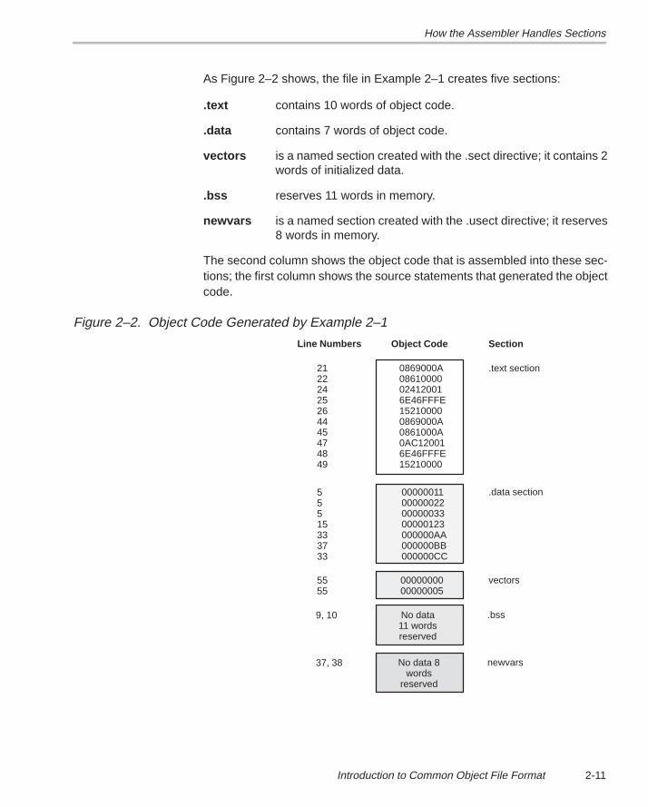
How the Assembler Handles Sections
2-11Introduction to Common Object File Format
As Figure 2–2 shows, the file in Example 2–1 creates five sections:
.text contains 10 words of object code.
.data contains 7 words of object code.
vectors is a named section created with the .sect directive; it contains 2words of initialized data.
.bss reserves 11 words in memory.
newvars is a named section created with the .usect directive; it reserves8 words in memory.
The second column shows the object code that is assembled into these sec-tions; the first column shows the source statements that generated the objectcode.
Figure 2–2. Object Code Generated by Example 2–1
0000000000000005
No data11 wordsreserved
No data 8words
reserved
00000011000000220000003300000123000000AA000000BB000000CC
0869000A08610000024120016E46FFFE152100000869000A0861000A0AC120016E46FFFE15210000
5555
Line Numbers
21222425264445474849
55515333733
9, 10
37, 38
Object Code
.data section
vectors
.bss
newvars
Section
.text section
How the Linker Handles Sections
2-12
2.4 How the Linker Handles Sections
The linker has two main functions in regard to sections. First, the linker usesthe sections in COFF object files as building blocks; it combines input sections(when more than one file is being linked) to create output sections in an exe-cutable COFF output module. Second, the linker chooses memory addressesfor the output sections.
The linker provides two directives that support these functions:
� The MEMORY directive allows you to define the memory map of a targetsystem. You can name portions of memory and specify their starting ad-dresses and their lengths.
� The SECTIONS directive tells the linker how to combine input sectionsand where to place the output sections in memory.
It is not always necessary to use linker directives. If you don’t use them, thelinker uses the target processor’s default allocation algorithm described insubsection 2.4.1. When you do use linker directives, you must specify themin a linker command file.
Refer to the following sections for more information about linker command filesand linker directives:
Section Page8.4 Linker Command Files 8-18. . . . . . . . . . . . . . . . . . . . . . . . . . . . . . . . . . . . . 8.6 The MEMORY Directive 8-23. . . . . . . . . . . . . . . . . . . . . . . . . . . . . . . . . . . 8.7 The SECTIONS Directive 8-27. . . . . . . . . . . . . . . . . . . . . . . . . . . . . . . . . . 8.11 Default Allocation 8-47. . . . . . . . . . . . . . . . . . . . . . . . . . . . . . . . . . . . . . . . .
2.4.1 Default Allocation
You can link files without specifying a MEMORY or SECTIONS directive. Thelinker uses a default model to combine sections (if necessary) and allocatethem into memory. When using the default model, the linker
1) Assumes that memory begins at address 0h.
2) Assumes that 232 words are available to allocate object code into.
3) Allocates .text into memory, beginning at address 0.
4) Allocates .data into memory, immediately following .text.
5) Allocates .bss into memory, immediately following .data.
6) Allocates all named sections into memory, immediately following .bss.Named sections are allocated in the order that they’re encountered in theinput files.
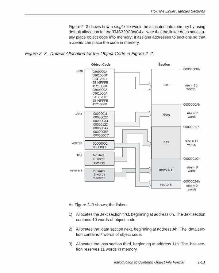
How the Linker Handles Sections
2-13Introduction to Common Object File Format
Figure 2–3 shows how a single file would be allocated into memory by usingdefault allocation for the TMS320C3x/C4x. Note that the linker does not actu-ally place object code into memory; it assigns addresses to sections so thata loader can place the code in memory.
Figure 2–3. Default Allocation for the Object Code in Figure 2–2
Section
.data
vectors
.bss
newvars
.text
00000000h
0000000Ah
00000011h
00000024h
0000001Ch
size = 10words
size = 7words
size = 11words
size = 8words
size = 2words
.data
vectors
.bss
newvars
.text
Object Code
0000000000000005
No data11 wordsreserved
No data 8 wordsreserved
00000011000000220000003300000123000000AA000000BB000000CC
0869000A08610000024120016E46FFFE152100000869000A0861000A0AC120016E46FFFE15210000
As Figure 2–3 shows, the linker:
1) Allocates the .text section first, beginning at address 0h. The .text sectioncontains 10 words of object code.
2) Allocates the .data section next, beginning at address Ah. The .data sec-tion contains 7 words of object code.
3) Allocates the .bss section third, beginning at address 11h. The .bss sec-tion reserves 11 words in memory.
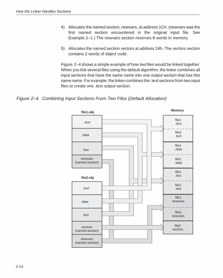
How the Linker Handles Sections
2-14
4) Allocates the named section, newvars, at address 1Ch. (newvars was thefirst named section encountered in the original input file. SeeExample 2–1.) The newvars section reserves 8 words in memory.
5) Allocates the named section vectors at address 24h. The vectors sectioncontains 2 words of object code.
Figure 2–4 shows a simple example of how two files would be linked together.When you link several files using the default algorithm, the linker combines allinput sections that have the same name into one output section that has thissame name. For example, the linker combines the .text sections from two inputfiles to create one .text output section.
Figure 2–4. Combining Input Sections From Two Files (Default Allocation)
.text
.data
.bss
Memory
.text
.data
.bss
newvars(named section)
newvars(named section)
file1.data
file1.bss
file1.text
file2.text
file1newvars
file2.data
file2.bss
file2newvars
file1.obj
file2.obj
vectors(named section)
file2vectors
How the Linker Handles Sections
2-15Introduction to Common Object File Format
In Figure 2–4, file1.obj and file2.obj each contain the .text, .data, and .bssdefault sections and a named section called newvars; file2.obj also containsa named section called vectors. As Figure 2–4 shows, the linker:
1) Combines file1.text with file2.text to form one .text output section. The.text output section is allocated at address 0h.
2) Combines file1 .data with file2 .data to form the .data output section. The.data output section is allocated following the .text output section.
3) Combines file1.bss with file2.bss to form the .bss output section. The .bssoutput section is allocated following the .data output section.
4) Combines file1 newvars with file2 newvars to form the newvars outputsection. (The newvars section is the first named section that is encoun-tered during the link, so it is allocated before the second named section,vectors.) The newvars output section is allocated following the .bss outputsection.
5) Allocates the vectors section from file2 after the newvars section.
For more information about default allocation algorithms, refer to Section 8.11on page 8-47.
2.4.2 Placing Sections in the Memory Map
Figure 2–3 and Figure 2–4 illustrate the linker’s default methods for combiningsections and allocating them into memory. Sometimes you may not want touse the default setup. For example, you may not want to combine all of the .textsections into a single .text section. Or, you might want a named section placedat address 40h instead of the .text section. Most memory maps are composedof various types of memories (DRAM, ROM, EPROM, etc.) in varyingamounts; you may want to place a section in a particular type of memory.
The next two illustrations show another possible combination of the sectionsfrom Figure 2–3:
Example 2–2 contains linker MEMORY and SECTIONS definitions.
Figure 2–5 shows how the sections from Example 2–2 are allocated into thememory map.
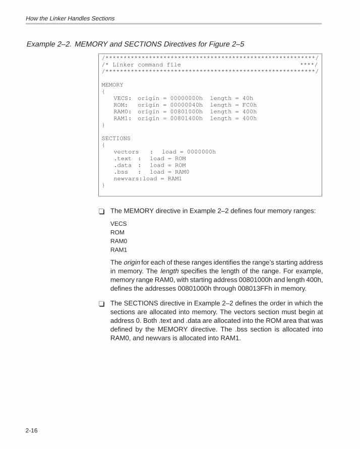
How the Linker Handles Sections
2-16
Example 2–2. MEMORY and SECTIONS Directives for Figure 2–5
/**********************************************************//* Linker command file ****//**********************************************************/
MEMORY{
VECS: origin = 00000000h length = 40hROM: origin = 00000040h length = FC0hRAM0: origin = 00801000h length = 400hRAM1: origin = 00801400h length = 400h
}
SECTIONS{
vectors : load = 0000000h.text : load = ROM.data : load = ROM.bss : load = RAM0newvars:load = RAM1
}
� The MEMORY directive in Example 2–2 defines four memory ranges:
VECSROMRAM0RAM1
The origin for each of these ranges identifies the range’s starting addressin memory. The length specifies the length of the range. For example,memory range RAM0, with starting address 00801000h and length 400h,defines the addresses 00801000h through 008013FFh in memory.
� The SECTIONS directive in Example 2–2 defines the order in which thesections are allocated into memory. The vectors section must begin ataddress 0. Both .text and .data are allocated into the ROM area that wasdefined by the MEMORY directive. The .bss section is allocated intoRAM0, and newvars is allocated into RAM1.
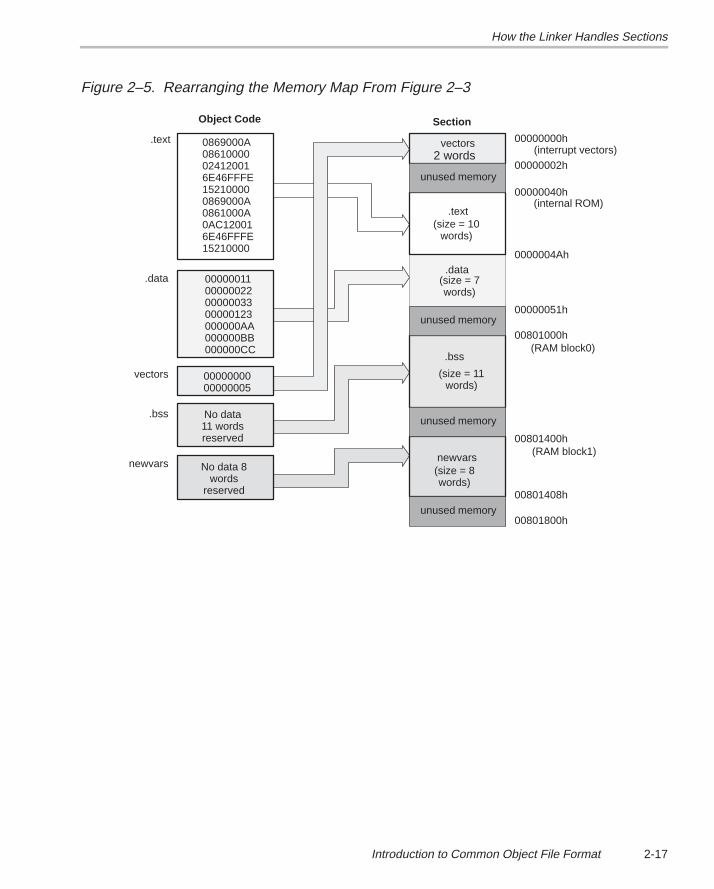
How the Linker Handles Sections
2-17Introduction to Common Object File Format
Figure 2–5. Rearranging the Memory Map From Figure 2–3
.data
vectors
.bss
newvars
.text
Object Code
0000000000000005
No data11 wordsreserved
No data 8words
reserved
00000011000000220000003300000123000000AA000000BB000000CC
0869000A08610000024120016E46FFFE152100000869000A0861000A0AC120016E46FFFE15210000
Section
.data
.bss
newvars
.text
00000000h
0000004Ah
00000051h
00801400h
(size = 10words)
(size = 7words)
(size = 11words)
(size = 8words)
2 words
.text
unused memory
unused memory
unused memory
unused memory
00000002h
vectors
00000040h
00801000h
00801408h
00801800h
(RAM block0)
(RAM block1)
(interrupt vectors)
(internal ROM)
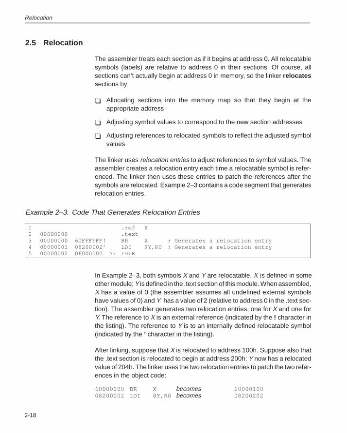
Relocation
2-18
2.5 Relocation
The assembler treats each section as if it begins at address 0. All relocatablesymbols (labels) are relative to address 0 in their sections. Of course, allsections can’t actually begin at address 0 in memory, so the linker relocatessections by:
� Allocating sections into the memory map so that they begin at theappropriate address
� Adjusting symbol values to correspond to the new section addresses
� Adjusting references to relocated symbols to reflect the adjusted symbolvalues
The linker uses relocation entries to adjust references to symbol values. Theassembler creates a relocation entry each time a relocatable symbol is refer-enced. The linker then uses these entries to patch the references after thesymbols are relocated. Example 2–3 contains a code segment that generatesrelocation entries.
Example 2–3. Code That Generates Relocation Entries
1 .ref X2 00000000 .text3 00000000 60FFFFFF! BR X ; Generates a relocation entry4 00000001 08200002’ LDI @Y,R0 ; Generates a relocation entry5 00000002 06000000 Y: IDLE
In Example 2–3, both symbols X and Y are relocatable. X is defined in someother module; Y is defined in the .text section of this module. When assembled,X has a value of 0 (the assembler assumes all undefined external symbolshave values of 0) and Y has a value of 2 (relative to address 0 in the .text sec-tion). The assembler generates two relocation entries, one for X and one forY. The reference to X is an external reference (indicated by the ! character inthe listing). The reference to Y is to an internally defined relocatable symbol(indicated by the ’ character in the listing).
After linking, suppose that X is relocated to address 100h. Suppose also thatthe .text section is relocated to begin at address 200h; Y now has a relocatedvalue of 204h. The linker uses the two relocation entries to patch the two refer-ences in the object code:
60000000 BR X becomes 6000010008200002 LDI @Y,R0 becomes 08200202
Relocation
2-19Introduction to Common Object File Format
Each section in a COFF object file has a table of relocation entries. The tablecontains one relocation entry for each relocatable reference in the section. Thelinker usually removes relocation entries after it uses them. This prevents theoutput file from being relocated again (if it is relinked or when it is loaded). Afile that contains no relocation entries is an absolute file (all of its addressesare absolute addresses). If you want the linker to retain relocation entries,invoke the linker with the –r option.
Runtime Relocation
2-20
2.6 Runtime Relocation
It may be necessary or desirable at times to load code into one area of memoryand run it in another. For example, you may have performance critical code ina ROM-based system. The code must be loaded into ROM but would run muchfaster if it were in RAM.
The linker provides a simple way to specify this. In the SECTIONS directive,you can optionally direct the linker to allocate a section twice: once to set itsload address, and again to set its run address.
Use the load keyword for the load address and the run keyword for the runaddress.
The load address determines where a loader will place the raw data for thesection. Any references to the section (such as labels in it) refer to its run ad-dress. The application must copy the section from its load address to its runaddress; this does not happen automatically just because you specify a sepa-rate run address.
If you provide only one allocation (either load or run) for a section, the sectionis allocated only once and will load and run at the same address. If you provideboth allocations, the section is actually allocated as if it were two different sec-tions of the same size.
Uninitialized sections (such as .bss) are not loaded, so the only address of sig-nificance is the run address. The linker allocates uninitialized sections onlyonce: if you specify both run and load addresses, the linker warns you and ig-nores the load address.
For a complete description of runtime relocation, see Section 8.8 onpage 8-35.
Loading a Program
2-21Introduction to Common Object File Format
2.7 Loading a Program
The linker produces executable COFF object modules. An executable objectfile has the same COFF format as object files that are used as linker input; how-ever, the sections in an executable object file are combined and relocated tofit into target memory.
In order to run a program, the data in the executable object module must betransferred, or loaded , into target system memory.
Several methods can be used for loading a program, depending on the execu-tion environment. Some of the more common situations are listed below.
� The TMS320C3x/C4x debugging tools, including the software simulator,XDS emulator, and software development system, have built-in loaders.Each of these tools has a LOAD command that invokes a COFF loader;the loader reads the executable file and copies the program into targetmemory.
� If you are using a ROM- or EPROM-based system, you can use the objectformat converter, which is shipped as part of the assembly language pack-age, to convert the executable COFF object module into one of severalhexadecimal object file formats. You can then use the converted file withan EPROM programmer to burn the program into an EPROM.
� Some TMS320C3x/C4x programs are loaded under the control of an oper-ating system or monitor software running directly on the target system. Inthis type of application, the target system usually has an interface to thefile system on which the executable module is stored. You must write acustom loader for this type of system. Refer to Appendix A for supplemen-tary information about the internal format of COFF object files. The loadermust comprehend the file system (in order to access the file) as well as thememory organization of the target system (to load the program into mem-ory).
Source code for the TMS320C3x/C4x COFF loader is available through theTI DSP bulletin board (call the DSP hotline listed in the front of this manual forinstructions). This loader provides all the basic mechanisms for reading aTMS320C3x/C4x COFF file and loading it into a target system. A simple inter-face allows customization to fit the requirements of most applications.
Symbols in a COFF File
2-22
2.8 Symbols in a COFF FileA COFF file contains a symbol table that stores information about symbols inthe program. The linker uses this table when it performs relocation. Debuggingtools can also use the symbol table to provide symbolic debugging.
2.8.1 External Symbols
External symbols are symbols that are defined in one module and referencedin another module. You can use the .global directive to identify symbols asexternal. In a source module, an external symbol can be either a ref or def:
Defined (DEF) Defined in the current module and used in anothermodule
Referenced (REF) Referenced in the current module, but defined in an-other module
The following code segment illustrates these definitions.
.global x ; DEF of x
.global y ; REF of yx: LDI R0,R1 ; Define x
LDI @y,R0 ; Reference y
The .global definition of x says that it is an external symbol defined in this mod-ule and that other modules can reference x. The .global definition of y says thatit is an undefined symbol that is defined in some other module.
The assembler places both x and y in the object file’s symbol table. When thefile is linked with other object files, the entry for x defines unresolved refer-ences to x from other files. The entry for y causes the linker to look through thesymbol tables of other files for y’s definition.
The linker must match all references with corresponding definitions. If thelinker cannot find a symbol’s definition, it prints an error message about theunresolved reference. This type of error prevents the linker from creating anexecutable object module.
2.8.2 The Symbol Table
The assembler always generates an entry in the symbol table when it encoun-ters an external symbol (both definitions and references). The assembler alsocreates special symbols that point to the beginning of each section; the linkeruses these symbols to relocate references to other symbols in a section.
The assembler does not usually create symbol table entries for any other typeof symbol, because the linker does not use them. For example, labels are notincluded in the symbol table unless they are declared with .global. For sym-bolic debugging purposes, it is sometimes useful to have entries in the symboltable for each symbol in a program. To accomplish this, invoke the assemblerwith the –s option.
3-1Assembler Description
Assembler Description
The assembler translates assembly-language source files into object files.These files are in common object file format (COFF), which is discussed inChapter 2 and Appendix A. Source files can contain the following assemblylanguage elements:
Assembler directives described in Chapter 4
Assembly language instructions described in Chapter 5
Macro directives described in Chapter 6
Topic Page
3.1 Assembler Overview 3-2. . . . . . . . . . . . . . . . . . . . . . . . . . . . . . . . . . . . . . . . . .
3.2 Assembler Development Flow 3-3. . . . . . . . . . . . . . . . . . . . . . . . . . . . . . . . . .
3.3 Invoking the Assembler 3-4. . . . . . . . . . . . . . . . . . . . . . . . . . . . . . . . . . . . . . .
3.4 Porting Upward Compatible Code 3-6. . . . . . . . . . . . . . . . . . . . . . . . . . . . . .
3.5 Naming Alternate Directories for Assembler Input 3-7. . . . . . . . . . . . . . .
3.6 Source Statement Format 3-10. . . . . . . . . . . . . . . . . . . . . . . . . . . . . . . . . . . . .
3.7 Constants 3-12. . . . . . . . . . . . . . . . . . . . . . . . . . . . . . . . . . . . . . . . . . . . . . . . . . .
3.8 Character Strings 3-15. . . . . . . . . . . . . . . . . . . . . . . . . . . . . . . . . . . . . . . . . . . .
3.9 Symbols 3-16. . . . . . . . . . . . . . . . . . . . . . . . . . . . . . . . . . . . . . . . . . . . . . . . . . . .
3.10 Expressions 3-20. . . . . . . . . . . . . . . . . . . . . . . . . . . . . . . . . . . . . . . . . . . . . . . . .
3.11 Source Listings 3-25. . . . . . . . . . . . . . . . . . . . . . . . . . . . . . . . . . . . . . . . . . . . . .
3.12 Cross-Reference Listings 3-27. . . . . . . . . . . . . . . . . . . . . . . . . . . . . . . . . . . . .
Chapter 3
Assembler Overview
3-2
3.1 Assembler Overview
The assembler does the following:
� Processes the source statements in a text file to produce a relocatableobject file
� Produces a source listing (if requested) and provides you with control overthis listing
� Allows you to segment your code into sections and maintain an SPC(section program counter) for each section of object code
� Defines and references global symbols and appends a cross-referencelisting to the source listing (if requested)
� Assembles conditional blocks
� Supports macros, allowing you to define macros inline or in a library
� Allows you to assemble TMS320C3x and TMS320C4x code
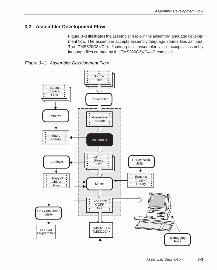
Assembler Development Flow
3-3Assembler Description
3.2 Assembler Development Flow
Figure 3–1 illustrates the assembler’s role in the assembly language develop-ment flow. The assembler accepts assembly language source files as input.The TMS320C3x/C4x floating-point assembler also accepts assemblylanguage files created by the TMS320C3x/C4x C compiler.
Figure 3–1. Assembler Development Flow
Linker
C Compiler
Archiver
MacroLibrary
MacroSourceFiles
Archiver
Library ofObjectFiles
Hex ConversionUtility
EPROMProgrammer
Debugging Tools
CSourceFiles
AssemblerSource
COFFObjectFiles
TMS320C3xTMS320C4x
ExecutableCOFF
File
RuntimeSupportLibrary
Assembler
Library Build Utility
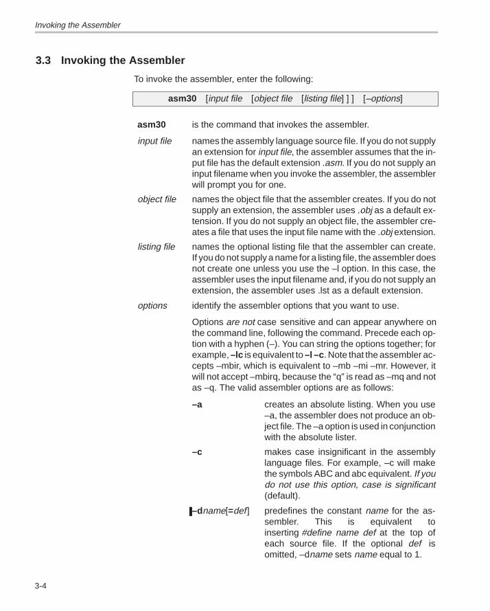
Invoking the Assembler
3-4
3.3 Invoking the Assembler
To invoke the assembler, enter the following:
asm30 [input file [object file [listing file] ] ] [–options]
asm30
input file
is the command that invokes the assembler.
names the assembly language source file. If you do not supplyan extension for input file, the assembler assumes that the in-put file has the default extension .asm. If you do not supply aninput filename when you invoke the assembler, the assemblerwill prompt you for one.
object file names the object file that the assembler creates. If you do notsupply an extension, the assembler uses .obj as a default ex-tension. If you do not supply an object file, the assembler cre-ates a file that uses the input file name with the .obj extension.
listing file names the optional listing file that the assembler can create.If you do not supply a name for a listing file, the assembler doesnot create one unless you use the –l option. In this case, theassembler uses the input filename and, if you do not supply anextension, the assembler uses .lst as a default extension.
options identify the assembler options that you want to use.
Options are not case sensitive and can appear anywhere onthe command line, following the command. Precede each op-tion with a hyphen (–). You can string the options together; forexample, –lc is equivalent to –l –c . Note that the assembler ac-cepts –mbir, which is equivalent to –mb –mi –mr. However, itwill not accept –mbirq, because the “q” is read as –mq and notas –q. The valid assembler options are as follows:
–a creates an absolute listing. When you use–a, the assembler does not produce an ob-ject file. The –a option is used in conjunctionwith the absolute lister.
–c makes case insignificant in the assemblylanguage files. For example, –c will makethe symbols ABC and abc equivalent. If youdo not use this option, case is significant(default).
–dname[=def] predefines the constant name for the as-sembler. This is equivalent toinserting #define name def at the top ofeach source file. If the optional def isomitted, –dname sets name equal to 1.
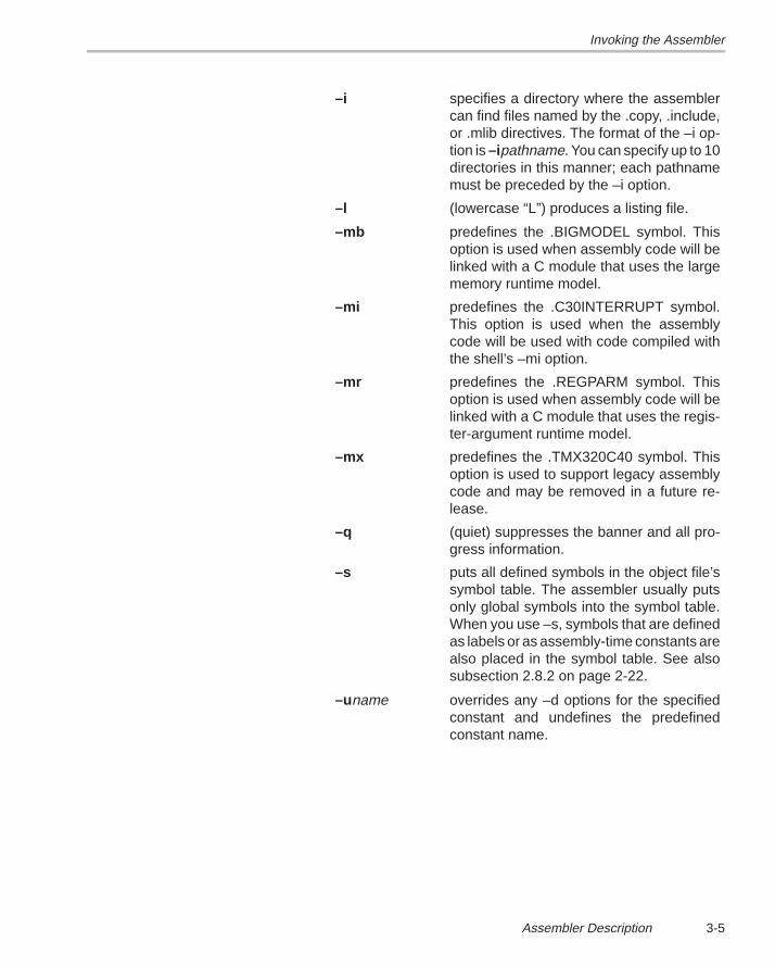
Invoking the Assembler
3-5Assembler Description
–i specifies a directory where the assemblercan find files named by the .copy, .include,or .mlib directives. The format of the –i op-tion is –ipathname. You can specify up to 10directories in this manner; each pathnamemust be preceded by the –i option.
–l (lowercase “L”) produces a listing file.
–mb predefines the .BIGMODEL symbol. Thisoption is used when assembly code will belinked with a C module that uses the largememory runtime model.
–mi predefines the .C30INTERRUPT symbol.This option is used when the assemblycode will be used with code compiled withthe shell’s –mi option.
–mr predefines the .REGPARM symbol. Thisoption is used when assembly code will belinked with a C module that uses the regis-ter-argument runtime model.
–mx predefines the .TMX320C40 symbol. Thisoption is used to support legacy assemblycode and may be removed in a future re-lease.
–q (quiet) suppresses the banner and all pro-gress information.
–s puts all defined symbols in the object file’ssymbol table. The assembler usually putsonly global symbols into the symbol table.When you use –s, symbols that are definedas labels or as assembly-time constants arealso placed in the symbol table. See alsosubsection 2.8.2 on page 2-22.
–uname overrides any –d options for the specifiedconstant and undefines the predefinedconstant name.
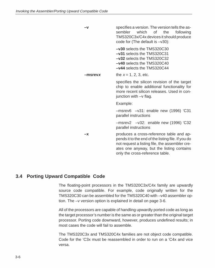
Porting Upward Compatible Code
3-6
–v specifies a version. The version tells the as-sembler which of the followingTMS320C3x/C4x devices it should producecode for (The default is –v30):
–v30 selects the TMS320C30–v31 selects the TMS320C31–v32 selects the TMS320C32–v40 selects the TMS320C40–v44 selects the TMS320C44
–msrev x the x = 1, 2, 3, etc.
specifies the silicon revision of the targetchip to enable additional functionality formore recent silicon releases. Used in con-junction with –v flag.
Example:
–msrev6 –v31: enable new (1996) ’C31parallel instructions
–msrev2 –v32: enable new (1996) ’C32parallel instructions
–x produces a cross-reference table and ap-pends it to the end of the listing file. If you donot request a listing file, the assembler cre-ates one anyway, but the listing containsonly the cross-reference table.
3.4 Porting Upward Compatible Code
The floating-point processors in the TMS320C3x/C4x family are upwardlysource code compatible. For example, code originally written for theTMS320C30 can be assembled for the TMS320C40 with –v40 assembler op-tion. The –v version option is explained in detail on page 3-6.
All of the processors are capable of handling upwardly ported code as long asthe target processor’s number is the same as or greater than the original targetprocessor. Porting code downward, however, produces undefined results; inmost cases the code will fail to assemble.
The TMS320C3x and TMS320C4x families are not object code compatible.Code for the ’C3x must be reassembled in order to run on a ’C4x and viceversa.
Invoking the Assembler/Porting Upward Compatible Code
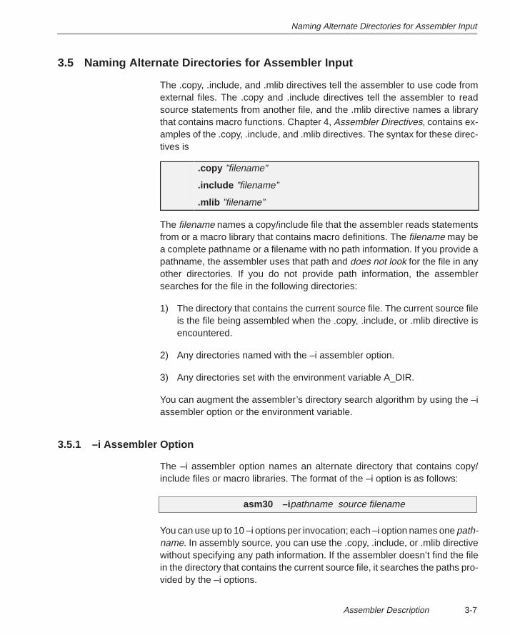
Naming Alternate Directories for Assembler Input
3-7Assembler Description
3.5 Naming Alternate Directories for Assembler Input
The .copy, .include, and .mlib directives tell the assembler to use code fromexternal files. The .copy and .include directives tell the assembler to readsource statements from another file, and the .mlib directive names a librarythat contains macro functions. Chapter 4, Assembler Directives, contains ex-amples of the .copy, .include, and .mlib directives. The syntax for these direc-tives is
.copy ”filename”
.include ”filename”
.mlib ”filename”
The filename names a copy/include file that the assembler reads statementsfrom or a macro library that contains macro definitions. The filename may bea complete pathname or a filename with no path information. If you provide apathname, the assembler uses that path and does not look for the file in anyother directories. If you do not provide path information, the assemblersearches for the file in the following directories:
1) The directory that contains the current source file. The current source fileis the file being assembled when the .copy, .include, or .mlib directive isencountered.
2) Any directories named with the –i assembler option.
3) Any directories set with the environment variable A_DIR.
You can augment the assembler’s directory search algorithm by using the –iassembler option or the environment variable.
3.5.1 –i Assembler Option
The –i assembler option names an alternate directory that contains copy/include files or macro libraries. The format of the –i option is as follows:
asm30 –i pathname source filename
You can use up to 10 –i options per invocation; each –i option names one path-name. In assembly source, you can use the .copy, .include, or .mlib directivewithout specifying any path information. If the assembler doesn’t find the filein the directory that contains the current source file, it searches the paths pro-vided by the –i options.
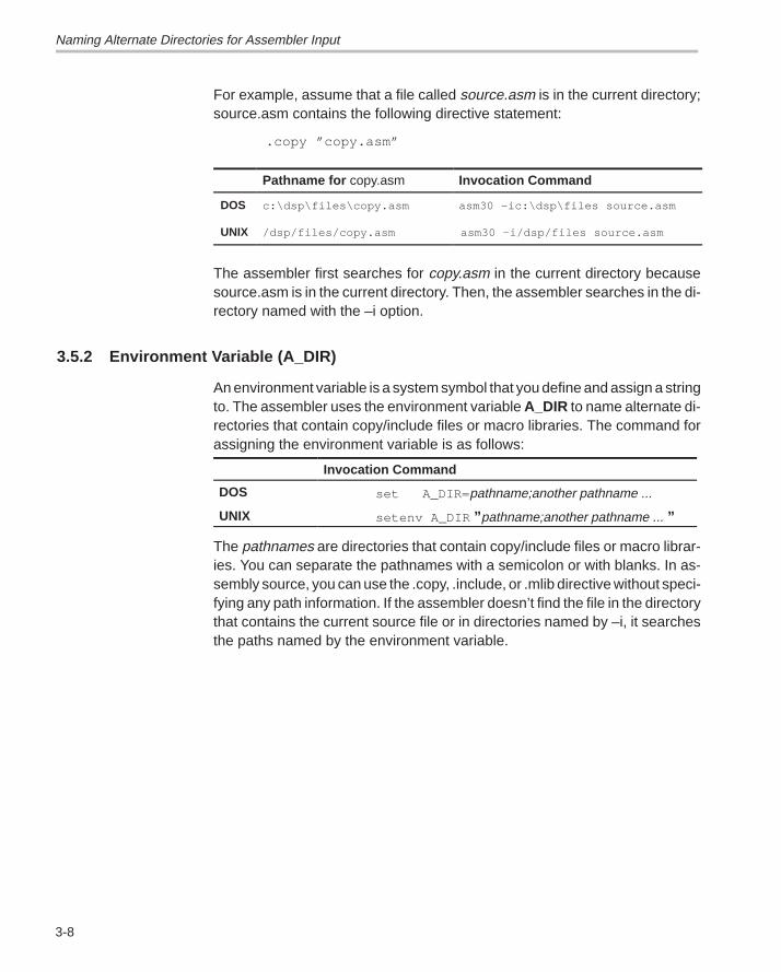
Naming Alternate Directories for Assembler Input
3-8
For example, assume that a file called source.asm is in the current directory;source.asm contains the following directive statement:
.copy ”copy.asm”
Pathname for copy.asm Invocation Command
DOS c:\dsp\files\copy.asm asm30 –ic:\dsp\files source.asm
UNIX /dsp/files/copy.asm asm30 –i/dsp/files source.asm
The assembler first searches for copy.asm in the current directory becausesource.asm is in the current directory. Then, the assembler searches in the di-rectory named with the –i option.
3.5.2 Environment Variable (A_DIR)
An environment variable is a system symbol that you define and assign a stringto. The assembler uses the environment variable A_DIR to name alternate di-rectories that contain copy/include files or macro libraries. The command forassigning the environment variable is as follows:
Invocation Command
DOS set A_DIR= pathname;another pathname ...
UNIX setenv A_DIR ” pathname;another pathname ... ”
The pathnames are directories that contain copy/include files or macro librar-ies. You can separate the pathnames with a semicolon or with blanks. In as-sembly source, you can use the .copy, .include, or .mlib directive without speci-fying any path information. If the assembler doesn’t find the file in the directorythat contains the current source file or in directories named by –i, it searchesthe paths named by the environment variable.
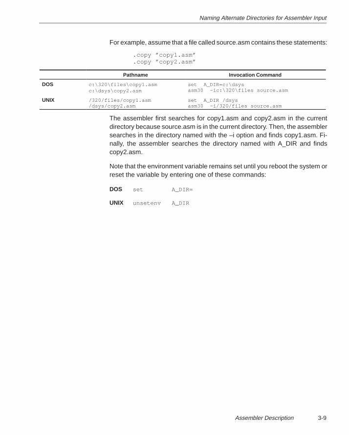
Naming Alternate Directories for Assembler Input
3-9Assembler Description
For example, assume that a file called source.asm contains these statements:
.copy ”copy1.asm”
.copy ”copy2.asm”
Pathname Invocation Command
DOS c:\320\files\copy1.asmc:\dsys\copy2.asm
set A_DIR=c:\dsysasm30 –ic:\320\files source.asm
UNIX /320/files/copy1.asm/dsys/copy2.asm
set A_DIR /dsysasm30 –i/320/files source.asm
The assembler first searches for copy1.asm and copy2.asm in the currentdirectory because source.asm is in the current directory. Then, the assemblersearches in the directory named with the –i option and finds copy1.asm. Fi-nally, the assembler searches the directory named with A_DIR and findscopy2.asm.
Note that the environment variable remains set until you reboot the system orreset the variable by entering one of these commands:
DOS set A_DIR=
UNIX unsetenv A_DIR
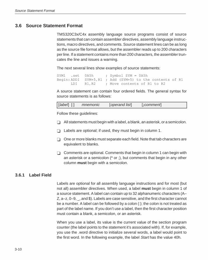
Source Statement Format
3-10
3.6 Source Statement Format
TMS320C3x/C4x assembly language source programs consist of sourcestatements that can contain assembler directives, assembly language instruc-tions, macro directives, and comments. Source statement lines can be as longas the source file format allows, but the assembler reads up to 200 charactersper line. If a statement contains more than 200 characters, the assembler trun-cates the line and issues a warning.
The next several lines show examples of source statements:
SYM1 .set 0A5h ; Symbol SYM = 0A5hBegin: ADDI SYM+5,R1 ; Add (SYM+5) to the contents of R1
LDI R1,R2 ; Move contents of R1 to R2
A source statement can contain four ordered fields. The general syntax forsource statements is as follows:
[label ] [:] mnemonic [operand list ] [;comment]
Follow these guidelines:
� All statements must begin with a label, a blank, an asterisk, or a semicolon.
� Labels are optional; if used, they must begin in column 1.
� One or more blanks must separate each field. Note that tab characters areequivalent to blanks.
� Comments are optional. Comments that begin in column 1 can begin withan asterisk or a semicolon (* or ;), but comments that begin in any othercolumn must begin with a semicolon.
3.6.1 Label Field
Labels are optional for all assembly language instructions and for most (butnot all) assembler directives. When used, a label must begin in column 1 ofa source statement. A label can contain up to 32 alphanumeric characters (A–Z, a–z, 0–9, _, and $). Labels are case sensitive, and the first character cannotbe a number. A label can be followed by a colon (:); the colon is not treated aspart of the label name. If you don’t use a label, then the first character positionmust contain a blank, a semicolon, or an asterisk.
When you use a label, its value is the current value of the section programcounter (the label points to the statement it’s associated with). If, for example,you use the .word directive to initialize several words, a label would point tothe first word. In the following example, the label Start has the value 40h.
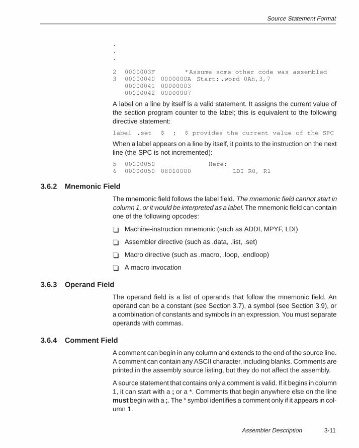
Source Statement Format
3-11Assembler Description
.
.
.
2 0000003F *Assume some other code was assembled3 00000040 0000000A Start: .word 0Ah,3,7
00000041 0000000300000042 00000007
A label on a line by itself is a valid statement. It assigns the current value ofthe section program counter to the label; this is equivalent to the followingdirective statement:
label .set $ ; $ provides the current value of the SPC
When a label appears on a line by itself, it points to the instruction on the nextline (the SPC is not incremented):
5 00000050 Here:6 00000050 08010000 LDI R0, R1
3.6.2 Mnemonic Field
The mnemonic field follows the label field. The mnemonic field cannot start incolumn 1, or it would be interpreted as a label. The mnemonic field can containone of the following opcodes:
� Machine-instruction mnemonic (such as ADDI, MPYF, LDI)
� Assembler directive (such as .data, .list, .set)
� Macro directive (such as .macro, .loop, .endloop)
� A macro invocation
3.6.3 Operand Field
The operand field is a list of operands that follow the mnemonic field. Anoperand can be a constant (see Section 3.7), a symbol (see Section 3.9), ora combination of constants and symbols in an expression. You must separateoperands with commas.
3.6.4 Comment Field
A comment can begin in any column and extends to the end of the source line.A comment can contain any ASCII character, including blanks. Comments areprinted in the assembly source listing, but they do not affect the assembly.
A source statement that contains only a comment is valid. If it begins in column1, it can start with a ; or a *. Comments that begin anywhere else on the linemust begin with a ;. The * symbol identifies a comment only if it appears in col-umn 1.
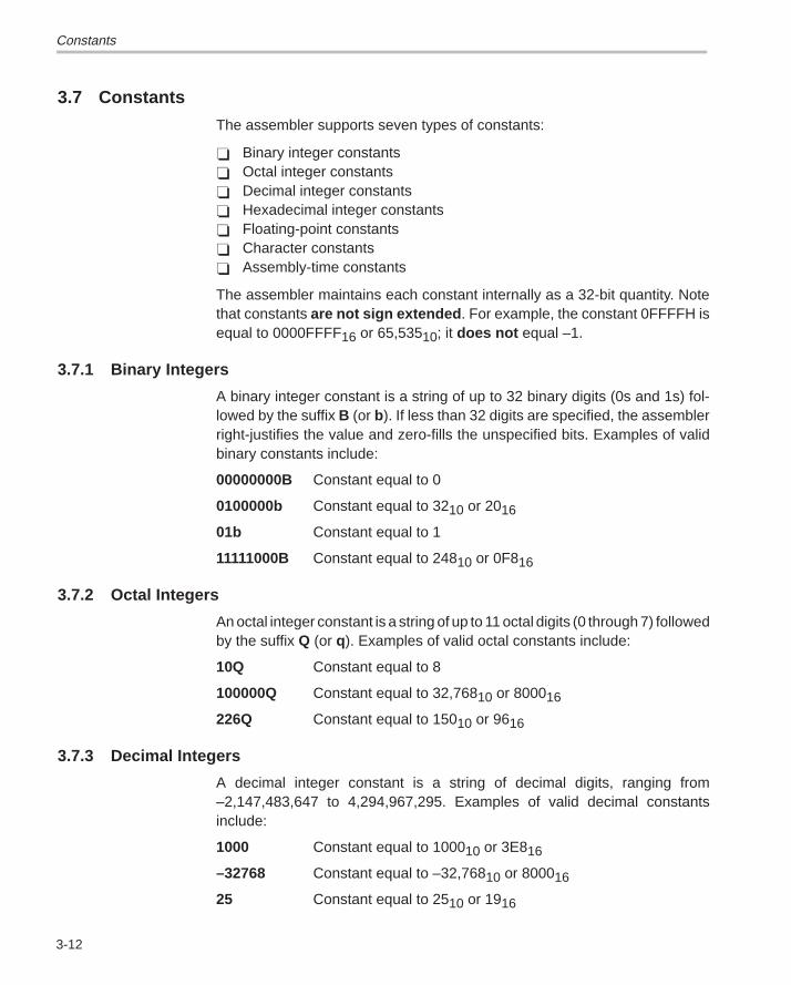
Constants
3-12
3.7 Constants
The assembler supports seven types of constants:
� Binary integer constants� Octal integer constants� Decimal integer constants� Hexadecimal integer constants� Floating-point constants � Character constants� Assembly-time constants
The assembler maintains each constant internally as a 32-bit quantity. Notethat constants are not sign extended . For example, the constant 0FFFFH isequal to 0000FFFF16 or 65,53510; it does not equal –1.
3.7.1 Binary Integers
A binary integer constant is a string of up to 32 binary digits (0s and 1s) fol-lowed by the suffix B (or b). If less than 32 digits are specified, the assemblerright-justifies the value and zero-fills the unspecified bits. Examples of validbinary constants include:
00000000B Constant equal to 0
0100000b Constant equal to 3210 or 2016
01b Constant equal to 1
11111000B Constant equal to 24810 or 0F816
3.7.2 Octal Integers
An octal integer constant is a string of up to 11 octal digits (0 through 7) followedby the suffix Q (or q). Examples of valid octal constants include:
10Q Constant equal to 8
100000Q Constant equal to 32,76810 or 800016
226Q Constant equal to 15010 or 9616
3.7.3 Decimal Integers
A decimal integer constant is a string of decimal digits, ranging from–2,147,483,647 to 4,294,967,295. Examples of valid decimal constantsinclude:
1000 Constant equal to 100010 or 3E816
–32768 Constant equal to –32,76810 or 800016
25 Constant equal to 2510 or 1916
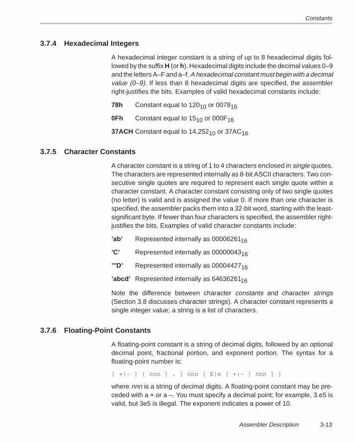
Constants
3-13Assembler Description
3.7.4 Hexadecimal Integers
A hexadecimal integer constant is a string of up to 8 hexadecimal digits fol-lowed by the suffix H (or h). Hexadecimal digits include the decimal values 0–9and the letters A–F and a–f. A hexadecimal constant must begin with a decimalvalue (0–9). If less than 8 hexadecimal digits are specified, the assemblerright-justifies the bits. Examples of valid hexadecimal constants include:
78h Constant equal to 12010 or 007816
0Fh Constant equal to 1510 or 000F16
37ACH Constant equal to 14,25210 or 37AC16
3.7.5 Character Constants
A character constant is a string of 1 to 4 characters enclosed in single quotes.The characters are represented internally as 8-bit ASCII characters. Two con-secutive single quotes are required to represent each single quote within acharacter constant. A character constant consisting only of two single quotes(no letter) is valid and is assigned the value 0. If more than one character isspecified, the assembler packs them into a 32-bit word, starting with the least-significant byte. If fewer than four characters is specified, the assembler right-justifies the bits. Examples of valid character constants include:
’ab’ Represented internally as 0000626116
’C’ Represented internally as 0000004316
’’’D’ Represented internally as 0000442716
’abcd’ Represented internally as 6463626116
Note the difference between character constants and character strings(Section 3.8 discusses character strings). A character constant represents asingle integer value; a string is a list of characters.
3.7.6 Floating-Point Constants
A floating-point constant is a string of decimal digits, followed by an optionaldecimal point, fractional portion, and exponent portion. The syntax for afloating-point number is:
[ +|– ] [ nnn ] . [ nnn [ E|e [ +|– ] nnn ] ]
where nnn is a string of decimal digits. A floating-point constant may be pre-ceded with a + or a –. You must specify a decimal point; for example, 3.e5 isvalid, but 3e5 is illegal. The exponent indicates a power of 10.
Constants
3-14
Valid floating-point constants include:
3.0
3.14
.3
–0.314e13
+314.59e–2
For more information about floating-point format, refer to the TMS320C3xUser’s Guide and the TMS320C4x User’s Guide.
3.7.7 Assembly-Time Constants
If you use the .set directive to assign a constant value to a symbol, the symbolbecomes an assembly-time constant. In order to use this constant in expres-sions, the value that is assigned to it must be absolute. For example:
sym .set 3LDI sym,R0 ; Load the constant 3 into R0
If you assign a floating-point constant to a symbol, then the symbol can beused only as a floating-point constant. Similarly, if you assign an integer con-stant to a symbol, then the symbol can be used only as an integer constant.The following example is illegal:
sym .set 3 ; Integer constantLDF sym,R0 ; Invalid – floating-point
; constant required
You can also use the .set directive to assign symbolic constants for registernames. In this case, the symbol becomes a synonym for the register:
sym .set R0LDI 10,sym
Character Strings
3-15Assembler Description
3.8 Character Strings
A character string is a string of characters enclosed in double quotes. Doublequotes that are part of character strings are represented by two consecutivedouble quotes. The maximum length of a string varies and is defined for eachdirective that requires a character string. Characters are represented inter-nally as 8-bit ASCII characters.
These are examples of valid character strings:
”sample program” defines a 14-character string, sample program
”PLAN ””C””” defines an 8-character string, PLAN ”C”
Character strings are used for the following:
� Filenames as in .copy ”filename”
� Section names as in .sect ”section name”
� Data initialization directives as in .byte ”charstring”
� Operand of .string directive
Symbols
3-16
3.9 Symbols
Symbols are used as labels, constants, and substitution symbols. A symbolname is a string of up to 32 alphanumeric characters (A–Z, a–z, 0–9, $, and_). The first character in a symbol cannot be a number; symbols cannot con-tain embedded blanks. The symbols you define are case sensitive; forexample, the assembler recognizes ABC, Abc, and abc as three unique sym-bols. You can override case sensitivity with the –c assembler option. This typeof symbol is valid only during the assembly in which it is defined, unless youuse the .global directive to declare it as an external symbol.
Note: If You Use the –c Option
If you use the –c option, the assembler translates all symbols to uppercase.If other modules that reference these symbols were not also assembled withthe –c option, the linker may fail to match global symbols.
3.9.1 Labels
Symbols that are used as labels become symbolic addresses that are asso-ciated with locations in the program. A label used locally within a file must beunique. Mnemonic opcodes and assembler directive names (without the ‘.’prefix) are valid label names.
Labels can also be used as the operand of a .global, .ref, .def, or .bss directive;for example,
.global label1
label2 nopadd label1b label2
3.9.2 Constants
Symbols can be set to constant values. By using constants, you can equatemeaningful names with constant values. The .set and .struct/.tag/.endstructdirectives enable you to set constants to symbolic names. Symbolic constantscannot be redefined. The following example shows how these directives canbe used:
Symbols
3-17Assembler Description
K .set 1024 ; constant definitionsmaxbuf .set 2*K
item .struct ; item structure definition.int value ; constant offsets value = 0.int delta ; constant offsets delta = 1
i_len .endstruct ; constant offset i_len = 2
array .tag item ; array declaration.bss array, i_len*K
LDI R0, array.delta ; array+1
The assembler also has several predefined symbolic constants; these are dis-cussed in the next section.
3.9.3 Symbolic Constants
The assembler has several predefined symbols, including the following:
� $, the dollar sign character, represents the current value of the sectionprogram counter (SPC).
� Register symbols :
AR0–AR7 IR0 RE R0–R7BK IR1 RC SPDP PC RS STand, for the ’C3x only;IF IE IOFplus, for the ’C4x only;R8–R11 DIE IIE IIF IVTPTVTP
� Version symbols are predefined assembler constants that you can useto direct the assembler to produce code for various target processors. Usethe version symbols with the target version switch or the .version directive.
Symbols Value Description.TMS320xx 30, 31, 32, 40, or 44 set according to –v flag.C3X or .C3x 1 or 0 1 if –v30, –v31, or –v32.C30 1 or 0 1 if –v30.C31 1 or 0 1 if –v31.C32 1 or 0 1 if –v32.C4X or .C4x 1 or 0 1 if –v40 or –v44.C40 1 or 0 1 if –v40.C44 1 or 0 1 if –v44
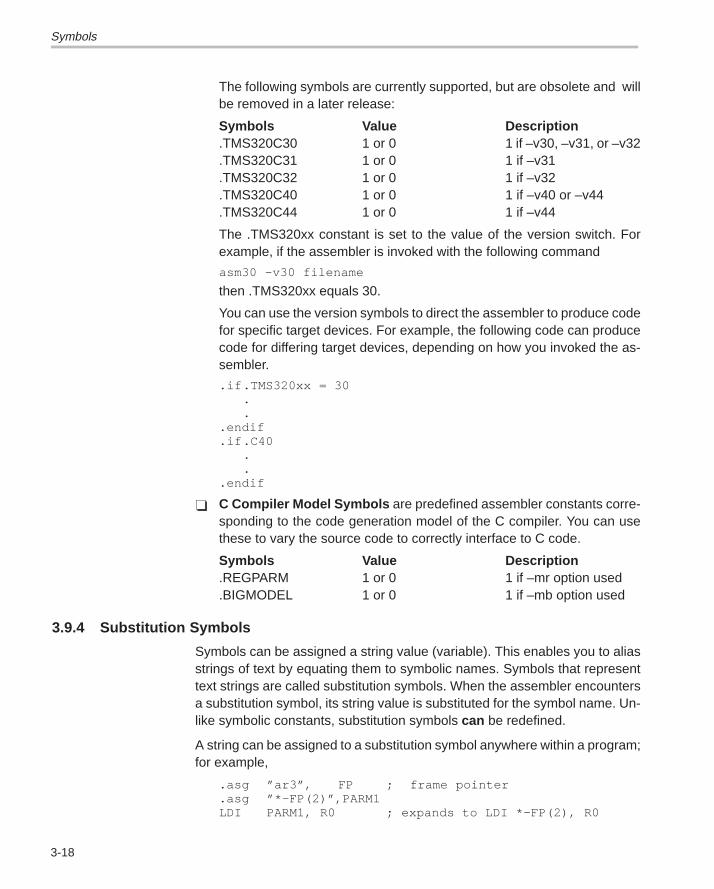
Symbols
3-18
The following symbols are currently supported, but are obsolete and willbe removed in a later release:
Symbols Value Description.TMS320C30 1 or 0 1 if –v30, –v31, or –v32.TMS320C31 1 or 0 1 if –v31.TMS320C32 1 or 0 1 if –v32.TMS320C40 1 or 0 1 if –v40 or –v44.TMS320C44 1 or 0 1 if –v44
The .TMS320xx constant is set to the value of the version switch. Forexample, if the assembler is invoked with the following command
asm30 –v30 filename
then .TMS320xx equals 30.
You can use the version symbols to direct the assembler to produce codefor specific target devices. For example, the following code can producecode for differing target devices, depending on how you invoked the as-sembler.
.if .TMS320xx = 30..
.endif
.if .C40..
.endif
� C Compiler Model Symbols are predefined assembler constants corre-sponding to the code generation model of the C compiler. You can usethese to vary the source code to correctly interface to C code.
Symbols Value Description.REGPARM 1 or 0 1 if –mr option used.BIGMODEL 1 or 0 1 if –mb option used
3.9.4 Substitution Symbols
Symbols can be assigned a string value (variable). This enables you to aliasstrings of text by equating them to symbolic names. Symbols that representtext strings are called substitution symbols. When the assembler encountersa substitution symbol, its string value is substituted for the symbol name. Un-like symbolic constants, substitution symbols can be redefined.
A string can be assigned to a substitution symbol anywhere within a program;for example,
.asg ”ar3”, FP ; frame pointer
.asg ”*–FP(2)”,PARM1LDI PARM1, R0 ; expands to LDI *–FP(2), R0
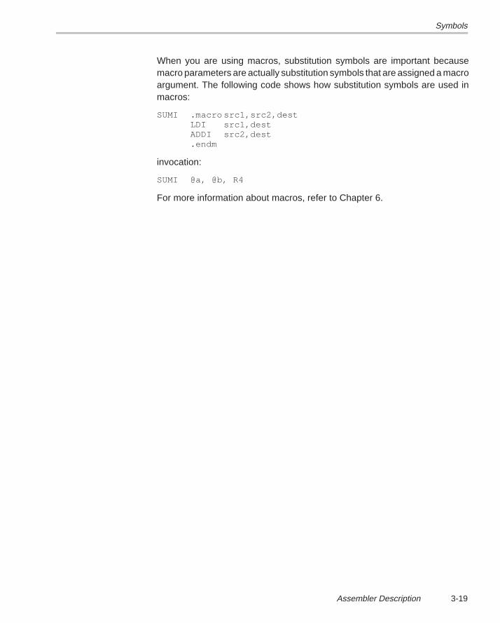
Symbols
3-19Assembler Description
When you are using macros, substitution symbols are important becausemacro parameters are actually substitution symbols that are assigned a macroargument. The following code shows how substitution symbols are used inmacros:
SUMI .macro src1,src2,destLDI src1,destADDI src2,dest.endm
invocation:
SUMI @a, @b, R4
For more information about macros, refer to Chapter 6.
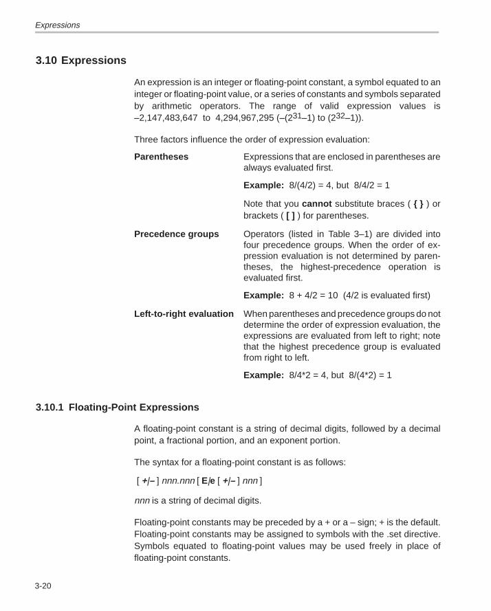
Expressions
3-20
3.10 Expressions
An expression is an integer or floating-point constant, a symbol equated to aninteger or floating-point value, or a series of constants and symbols separatedby arithmetic operators. The range of valid expression values is–2,147,483,647 to 4,294,967,295 (–(231–1) to (232–1)).
Three factors influence the order of expression evaluation:
Parentheses Expressions that are enclosed in parentheses arealways evaluated first.
Example: 8/(4/2) = 4, but 8/4/2 = 1
Note that you cannot substitute braces ( { } ) orbrackets ( [ ] ) for parentheses.
Precedence groups Operators (listed in Table 3–1) are divided intofour precedence groups. When the order of ex-pression evaluation is not determined by paren-theses, the highest-precedence operation isevaluated first.
Example: 8 + 4/2 = 10 (4/2 is evaluated first)
Left-to-right evaluation When parentheses and precedence groups do notdetermine the order of expression evaluation, theexpressions are evaluated from left to right; notethat the highest precedence group is evaluatedfrom right to left.
Example: 8/4*2 = 4, but 8/(4*2) = 1
3.10.1 Floating-Point Expressions
A floating-point constant is a string of decimal digits, followed by a decimalpoint, a fractional portion, and an exponent portion.
The syntax for a floating-point constant is as follows:
[ +|– ] nnn.nnn [ E|e [ +|– ] nnn ]
nnn is a string of decimal digits.
Floating-point constants may be preceded by a + or a – sign; + is the default.Floating-point constants may be assigned to symbols with the .set directive.Symbols equated to floating-point values may be used freely in place offloating-point constants.
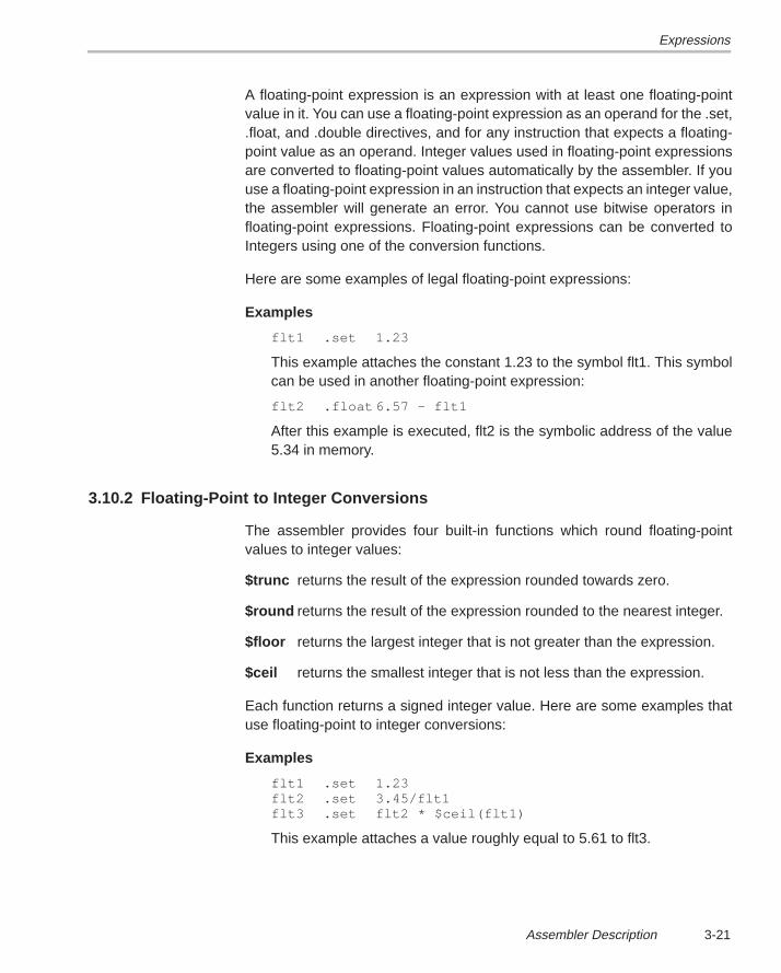
Expressions
3-21Assembler Description
A floating-point expression is an expression with at least one floating-pointvalue in it. You can use a floating-point expression as an operand for the .set,.float, and .double directives, and for any instruction that expects a floating-point value as an operand. Integer values used in floating-point expressionsare converted to floating-point values automatically by the assembler. If youuse a floating-point expression in an instruction that expects an integer value,the assembler will generate an error. You cannot use bitwise operators infloating-point expressions. Floating-point expressions can be converted toIntegers using one of the conversion functions.
Here are some examples of legal floating-point expressions:
Examples
flt1 .set 1.23
This example attaches the constant 1.23 to the symbol flt1. This symbolcan be used in another floating-point expression:
flt2 .float 6.57 – flt1
After this example is executed, flt2 is the symbolic address of the value5.34 in memory.
3.10.2 Floating-Point to Integer Conversions
The assembler provides four built-in functions which round floating-pointvalues to integer values:
$trunc returns the result of the expression rounded towards zero.
$round returns the result of the expression rounded to the nearest integer.
$floor returns the largest integer that is not greater than the expression.
$ceil returns the smallest integer that is not less than the expression.
Each function returns a signed integer value. Here are some examples thatuse floating-point to integer conversions:
Examples
flt1 .set 1.23flt2 .set 3.45/flt1flt3 .set flt2 * $ceil(flt1)
This example attaches a value roughly equal to 5.61 to flt3.
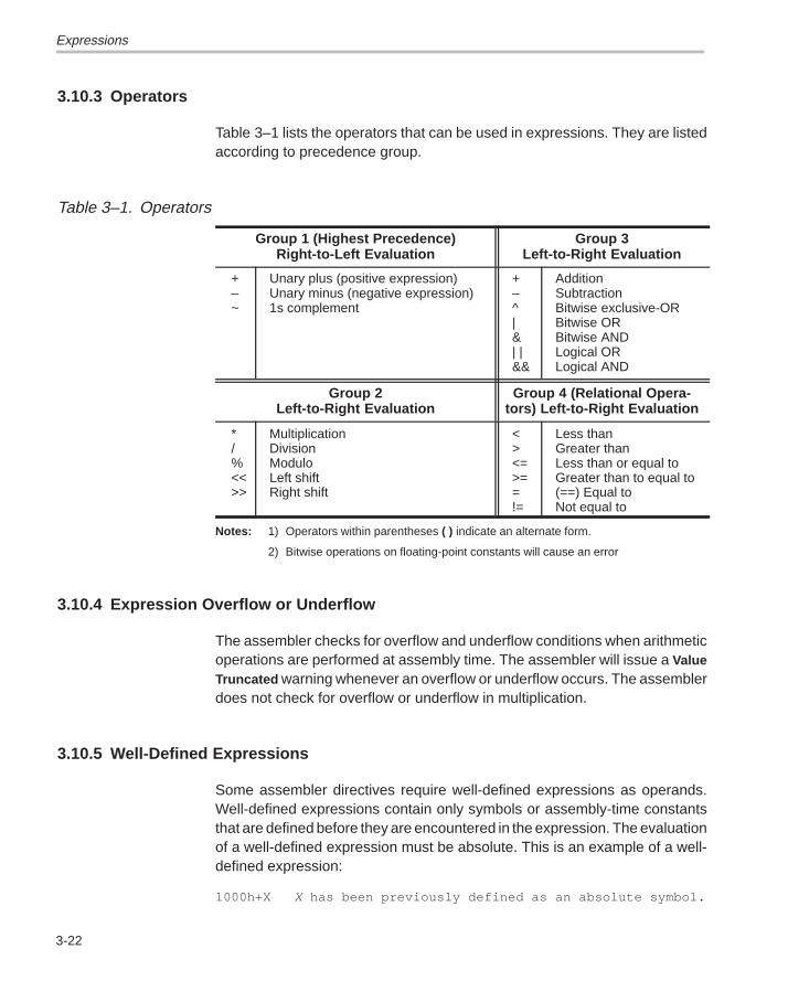
Expressions
3-22
3.10.3 Operators
Table 3–1 lists the operators that can be used in expressions. They are listedaccording to precedence group.
Table 3–1. Operators
Group 1 (Highest Precedence)Right-to-Left Evaluation
Group 3Left-to-Right Evaluation
+–~
Unary plus (positive expression)Unary minus (negative expression)1s complement
+–^|&| |&&
AdditionSubtractionBitwise exclusive-ORBitwise ORBitwise ANDLogical ORLogical AND
Group 2Left-to-Right Evaluation
Group 4 (Relational Opera-tors) Left-to-Right Evaluation
*/%<<>>
MultiplicationDivisionModuloLeft shiftRight shift
<><=>==!=
Less thanGreater thanLess than or equal to Greater than to equal to(==) Equal to Not equal to
Notes: 1) Operators within parentheses ( ) indicate an alternate form.
2) Bitwise operations on floating-point constants will cause an error
3.10.4 Expression Overflow or Underflow
The assembler checks for overflow and underflow conditions when arithmeticoperations are performed at assembly time. The assembler will issue a ValueTruncated warning whenever an overflow or underflow occurs. The assemblerdoes not check for overflow or underflow in multiplication.
3.10.5 Well-Defined Expressions
Some assembler directives require well-defined expressions as operands.Well-defined expressions contain only symbols or assembly-time constantsthat are defined before they are encountered in the expression. The evaluationof a well-defined expression must be absolute. This is an example of a well-defined expression:
1000h+X X has been previously defined as an absolute symbol.
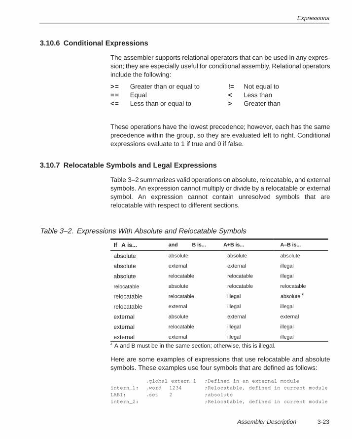
Expressions
3-23Assembler Description
3.10.6 Conditional Expressions
The assembler supports relational operators that can be used in any expres-sion; they are especially useful for conditional assembly. Relational operatorsinclude the following:
>= Greater than or equal to != Not equal to== Equal < Less than<= Less than or equal to > Greater than
These operations have the lowest precedence; however, each has the sameprecedence within the group, so they are evaluated left to right. Conditionalexpressions evaluate to 1 if true and 0 if false.
3.10.7 Relocatable Symbols and Legal Expressions
Table 3–2 summarizes valid operations on absolute, relocatable, and externalsymbols. An expression cannot multiply or divide by a relocatable or externalsymbol. An expression cannot contain unresolved symbols that arerelocatable with respect to different sections.
Table 3–2. Expressions With Absolute and Relocatable Symbols
If A is... and B is... A+B is... A–B is...
absolute absolute absolute absolute
absolute external external illegal
absolute relocatable relocatable illegal
relocatable absolute relocatable relocatable
relocatable relocatable illegal absolute †
relocatable external illegal illegal
external absolute external external
external relocatable illegal illegal
external external illegal illegal
† A and B must be in the same section; otherwise, this is illegal.
Here are some examples of expressions that use relocatable and absolutesymbols. These examples use four symbols that are defined as follows:
.global extern_1 ;Defined in an external moduleintern_1: .word 1234 ;Relocatable, defined in current moduleLAB1: .set 2 ;absoluteintern_2: ;Relocatable, defined in current module
Expressions
3-24
� Example 1
The statements in this example use an absolute symbol, LAB1. The firststatement puts the value 51 into register R0, the second statement putsthe value 8033h in R0, and the third puts 27 in memory address 8033h.
LDI LAB1 + ((4+3) * 7), AR0 ; AR0 = 51LDI LAB1 + 4 + 3 * 7, AR0 ; AR0 = 27
� Example 2
All legal expressions can be reduced to one of two forms:
relocatable symbol ± absolute symbol or
absolute value
Unary operators can be applied only to absolute values; they cannot beapplied to relocatable symbols. Expressions that cannot be reduced tocontain only one relocatable symbol are illegal. The first statement in thefollowing example is legal; the statements that follow it are invalid.
LDI extern_1 – 10, AR0 ;LegalLDI 10–extern_1, AR0 ;Can’t negate reloc. symbolLDI –(intern_1), AR0 ;Can’t negate reloc. symbolLDI extern_1/10, AR0 ;/isn’t an additive operatorLDI intern_1 + extern_1, AR0 ; Multiple relocatables
� Example 3
The first statement below is legal; although intern_1 and intern_2 arerelocatable, their difference is absolute because they’re in the samesection. Subtracting one relocatable symbol from another reduces theexpression to absolute value + relocatable symbol which is relocatable.The second statement is illegal because the sum of two relocatablesymbols is not an absolute value.
LDI intern_1 – intern_2 + extern_1,AR0 ; LegalLDI intern_1 + intern_2 + extern_1,AR0 ; Illegal
� Example 4
An external symbol’s placement in an expression is important to expres-sion evaluation. Although the statement below is similar to the firststatement in the previous example, it is illegal. This is because of left-to-right operator precedence; the assembler attempts to add intern_1 toextern_1.
LDI intern_1 + extern_2 – intern_2,AR0 ; Illegal
Source Listings
3-25Assembler Description
3.11 Source Listings
A source listing shows source statements and the object code they produce.To obtain a listing file, invoke the assembler with the –l (lowercase “L”) option.
At the top of each source listing page are two banner lines, a blank line, anda title line. Any title supplied by a .title directive is printed on this line; a pagenumber is printed to the right of the title. If you don’t use the .title directive, thetitle area is left blank. The assembler inserts a blank line below the title line.
Each line in the source file may produce a line in the listing file that shows asource statement number, an SPC value, the object code assembled, and thesource statement. A source statement may produce more than one word ofobject code. The assembler lists the SPC value and object code on a separateline for each additional word. Each additional line is listed immediately follow-ing the source statement line.
Field 1 Source Statement Number
Line Number
The source statement number is a decimal number. The assemblernumbers source lines as it encounters them in the source file; somestatements increment the line counter but are not listed (for exam-ple, .title statements and statements following a .nolist are notlisted). The difference between two consecutive source line num-bers indicates the number of statements in the source file that arenot listed.
Include File Letter
The assembler may precede a line with a letter; the letter indicatesthat the line is assembled from an include file.
Nesting Level Number
The assembler may precede a line with a number; the number indi-cates the nesting level of macro expansions and loop blocks.
Field 2 Section Program Counter
This field contains the section program counter, or SPC, value(hexadecimal). Each section (.text, .data, .bss, and named sec-tions) maintains a separate SPC. Some directives do not affect theSPC; they leave this field blank.
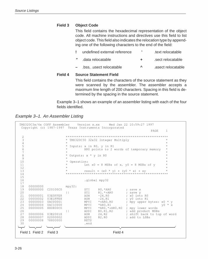
Source Listings
3-26
Field 3 Object CodeThis field contains the hexadecimal representation of the objectcode. All machine instructions and directives use this field to listobject code. This field also indicates the relocation type by append-ing one of the following characters to the end of the field:
! undefined external reference ’ .text relocatable
” .data relocatable + .sect relocatable
– .bss, .usect relocatable ^ .asect relocatable
Field 4 Source Statement FieldThis field contains the characters of the source statement as theywere scanned by the assembler. The assembler accepts amaximum line length of 200 characters. Spacing in this field is de-termined by the spacing in the source statement.
Example 3–1 shows an example of an assembler listing with each of the fourfields identified.
Example 3–1. An Assembler Listing
TMS320C3x/4x COFF Assembler Version x.xx Wed Jan 22 10:59:27 1997 Copyright (c) 1987–1997 Texas Instruments Incorporated
PAGE 1
2 *******************************************************3 * TMS320C30 32x32 Integer Multiply *4 * *5 * Inputs: x in R0, y in R1 *6 * AR0 points to 2 words of temporary memory *7 * *8 * Outputs: x * y in R0 *9 * *
10 * Operation: *11 * Let x0 = 8 MSBs of x, y0 = 8 MSBs of y *12 * *13 * result = (x0 * y) + (y0 * x) + xy *14 *******************************************************1516 .global mpy321718 00000000 mpy32:19 00000000 C20100C0 STI R0,*AR0 ; save x20 || STI R1,*+AR0 ; save y21 00000001 03E0FFE8 ASH –24,R0 ; x0 into R022 00000002 03E1FFE8 ASH –24,R1 ; y0 into R123 00000003 0AC00001 MPYI *+AR0,R0 ; mpy upper bytes: x0 * y24 00000004 0AC1C000 MPYI *AR0,R1 ; y0 * x25 00000005 880800C0 MPYI *AR0,*+AR0,R0 ; mpy lower words26 || ADDI R0,R1,R2 ; add product MSBs27 00000006 03E20018 ASH 24,R2 ; shift back to top of word28 00000007 02000002 ADDI R2,R0 ; add to LSBs29 00000008 78800000 RETS30 .end
Field 1 Field 2 Field 3 Field 4
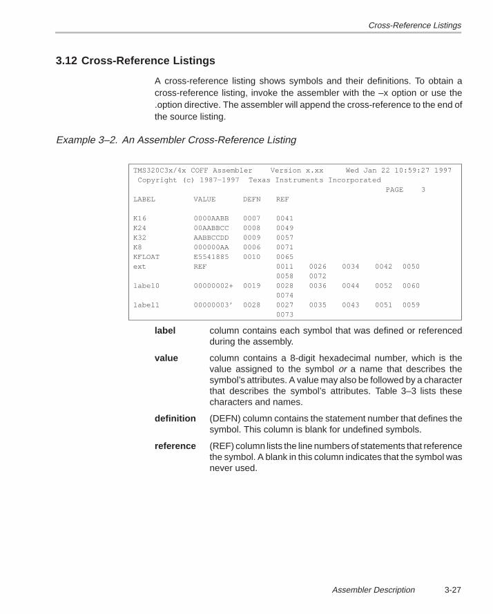
Cross-Reference Listings
3-27Assembler Description
3.12 Cross-Reference Listings
A cross-reference listing shows symbols and their definitions. To obtain across-reference listing, invoke the assembler with the –x option or use the.option directive. The assembler will append the cross-reference to the end ofthe source listing.
Example 3–2. An Assembler Cross-Reference Listing
TMS320C3x/4x COFF Assembler Version x.xx Wed Jan 22 10:59:27 1997 Copyright (c) 1987–1997 Texas Instruments Incorporated PAGE 3LABEL VALUE DEFN REF
K16 0000AABB 0007 0041K24 00AABBCC 0008 0049K32 AABBCCDD 0009 0057K8 000000AA 0006 0071KFLOAT E5541885 0010 0065ext REF 0011 0026 0034 0042 0050
0058 0072label0 00000002+ 0019 0028 0036 0044 0052 0060
0074label1 00000003’ 0028 0027 0035 0043 0051 0059
0073
label column contains each symbol that was defined or referencedduring the assembly.
value column contains a 8-digit hexadecimal number, which is thevalue assigned to the symbol or a name that describes thesymbol’s attributes. A value may also be followed by a characterthat describes the symbol’s attributes. Table 3–3 lists thesecharacters and names.
definition (DEFN) column contains the statement number that defines thesymbol. This column is blank for undefined symbols.
reference (REF) column lists the line numbers of statements that referencethe symbol. A blank in this column indicates that the symbol wasnever used.
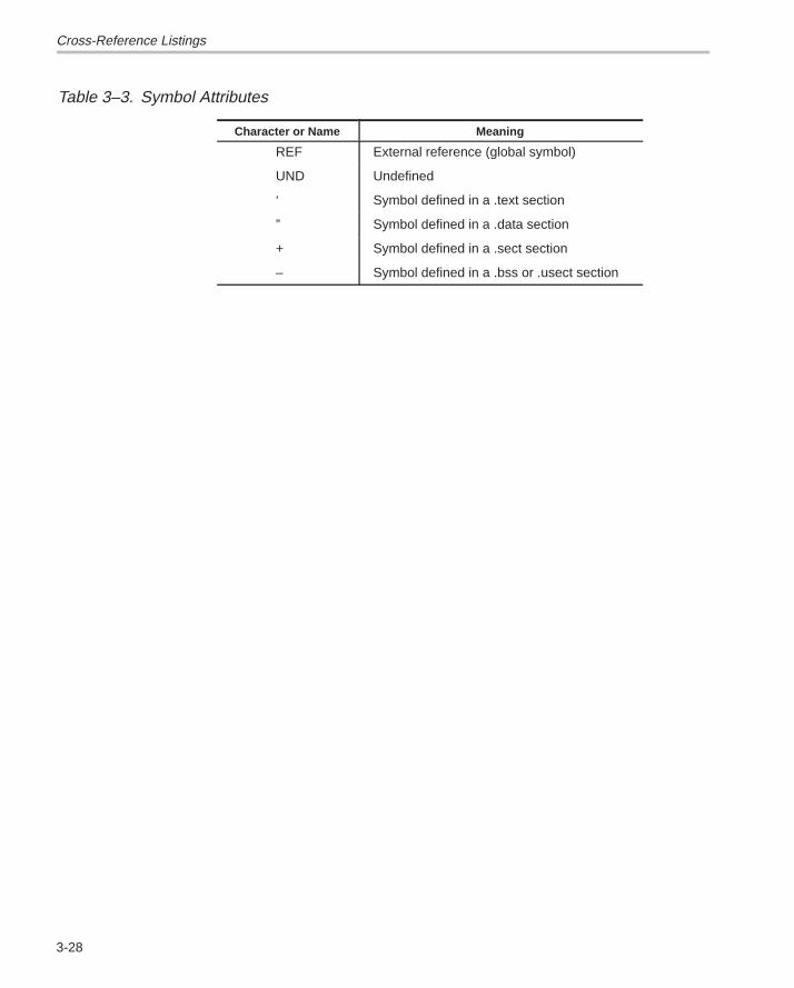
Cross-Reference Listings
3-28
Table 3–3. Symbol Attributes
Character or Name Meaning
REF External reference (global symbol)
UND Undefined
‘ Symbol defined in a .text section
” Symbol defined in a .data section
+ Symbol defined in a .sect section
– Symbol defined in a .bss or .usect section
4-1Assembler Directives
Assembler Directives
Assembler directives supply program data and control the assembly process.Assembler directives allow you to:
� Assemble code and data into specified sections
� Reserve space in memory for uninitialized variables
� Control the appearance of listings
� Initialize memory
� Assemble conditional blocks
� Define global variables
� Specify libraries that the assembler can obtain macros from
� Examine symbolic debugging information
This section is divided into two parts: the first part (Sections 4.1 through 4.9)describes the directives according to function, and the second part(Section 4.10) is an alphabetical reference. This section includes:
Topic Page
4.1 Directives Summary 4-2. . . . . . . . . . . . . . . . . . . . . . . . . . . . . . . . . . . . . . . . . . .
4.2 Directives That Define Sections 4-6. . . . . . . . . . . . . . . . . . . . . . . . . . . . . . . .
4.3 Directives That Initialize Constants 4-7. . . . . . . . . . . . . . . . . . . . . . . . . . . . .
4.4 Directives That Align the Section Program Counter 4-10. . . . . . . . . . . . .
4.5 Directives That Format the Output Listing 4-11. . . . . . . . . . . . . . . . . . . . . .
4.6 Directives That Reference Other Files 4-13. . . . . . . . . . . . . . . . . . . . . . . . .
4.7 Conditional Assembly Directives 4-14. . . . . . . . . . . . . . . . . . . . . . . . . . . . . .
4.8 Assembly-Time Symbol Directives 4-15. . . . . . . . . . . . . . . . . . . . . . . . . . . .
4.9 Miscellaneous Directives 4-16. . . . . . . . . . . . . . . . . . . . . . . . . . . . . . . . . . . . .
4.10 Directives Reference 4-17. . . . . . . . . . . . . . . . . . . . . . . . . . . . . . . . . . . . . . . . .
Chapter 4
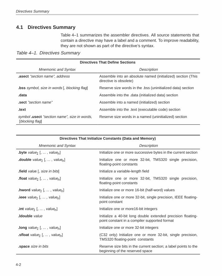
Directives Summary
4-2
4.1 Directives Summary
Table 4–1 summarizes the assembler directives. All source statements thatcontain a directive may have a label and a comment. To improve readability,they are not shown as part of the directive’s syntax.
Table 4–1. Directives Summary
Directives That Define Sections
Mnemonic and Syntax Description
.asect ”section name”, address Assemble into an absolute named (initialized) section (Thisdirective is obsolete)
.bss symbol, size in words [, blocking flag] Reserve size words in the .bss (uninitialized data) section
.data Assemble into the .data (initialized data) section
.sect ”section name” Assemble into a named (initialized) section
.text Assemble into the .text (executable code) section
symbol .usect ”section name”, size in words, [blocking flag]
Reserve size words in a named (uninitialized) section
Directives That Initialize Constants (Data and Memory)
Mnemonic and Syntax Description
.byte value1 [, ... , valuen] Initialize one or more successive bytes in the current section
.double value1 [, ... , valuen] Initialize one or more 32-bit, TMS320 single precision,floating-point constants
.field value [, size in bits] Initialize a variable-length field
.float value1 [, ... , valuen] Initialize one or more 32-bit, TMS320 single precision,floating-point constants
.hword value1 [, ... , valuen] Initialize one or more 16-bit (half-word) values
.ieee value1 [, ... , valuen] Initialize one or more 32-bit, single precision, IEEE floating-point constant
.int value1 [, ... , valuen] Initialize one or more16-bit integers
.ldouble value Initialize a 40-bit long double extended precision floating-point constant in a compiler supported format
.long value1 [, ... , valuen] Initialize one or more 32-bit integers
.sfloat value1 [, ... , valuen] (C32 only) Initialize one or more 32-bit, single precision,TMS320 floating-point constants
.space size in bits Reserve size bits in the current section; a label points to thebeginning of the reserved space
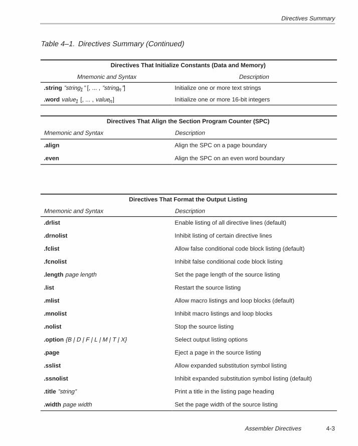
Directives Summary
4-3Assembler Directives
Table 4–1. Directives Summary (Continued)
Directives That Initialize Constants (Data and Memory)
Mnemonic and Syntax Description
.string ”string1” [, ... , ”stringn”] Initialize one or more text strings
.word value1 [, ... , valuen] Initialize one or more 16-bit integers
Directives That Align the Section Program Counter (SPC)
Mnemonic and Syntax Description
.align Align the SPC on a page boundary
.even Align the SPC on an even word boundary
Directives That Format the Output Listing
Mnemonic and Syntax Description
.drlist Enable listing of all directive lines (default)
.drnolist Inhibit listing of certain directive lines
.fclist Allow false conditional code block listing (default)
.fcnolist Inhibit false conditional code block listing
.length page length Set the page length of the source listing
.list Restart the source listing
.mlist Allow macro listings and loop blocks (default)
.mnolist Inhibit macro listings and loop blocks
.nolist Stop the source listing
.option {B | D | F | L | M | T | X} Select output listing options
.page Eject a page in the source listing
.sslist Allow expanded substitution symbol listing
.ssnolist Inhibit expanded substitution symbol listing (default)
.title ”string” Print a title in the listing page heading
.width page width Set the page width of the source listing
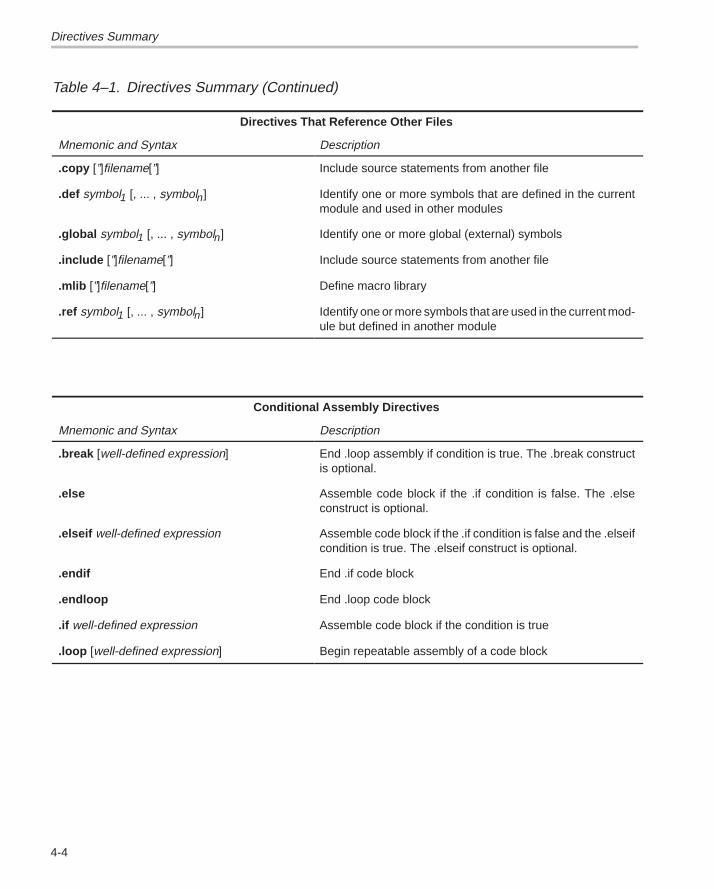
Directives Summary
4-4
Table 4–1. Directives Summary (Continued)
Directives That Reference Other Files
Mnemonic and Syntax Description
.copy [”]filename[”] Include source statements from another file
.def symbol1 [, ... , symboln] Identify one or more symbols that are defined in the currentmodule and used in other modules
.global symbol1 [, ... , symboln] Identify one or more global (external) symbols
.include [”]filename[”] Include source statements from another file
.mlib [”]filename[”] Define macro library
.ref symbol1 [, ... , symboln] Identify one or more symbols that are used in the current mod-ule but defined in another module
Conditional Assembly Directives
Mnemonic and Syntax Description
.break [well-defined expression] End .loop assembly if condition is true. The .break constructis optional.
.else Assemble code block if the .if condition is false. The .elseconstruct is optional.
.elseif well-defined expression Assemble code block if the .if condition is false and the .elseifcondition is true. The .elseif construct is optional.
.endif End .if code block
.endloop End .loop code block
.if well-defined expression Assemble code block if the condition is true
.loop [well-defined expression] Begin repeatable assembly of a code block
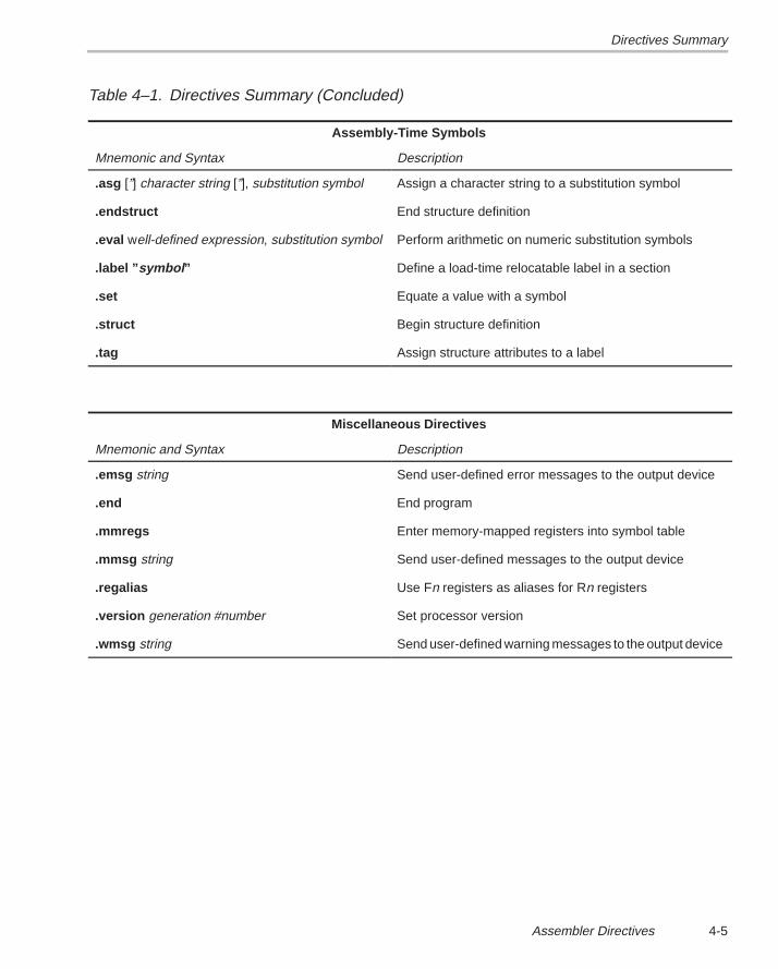
Directives Summary
4-5Assembler Directives
Table 4–1. Directives Summary (Concluded)
Assembly-Time Symbols
Mnemonic and Syntax Description
.asg [”] character string [”], substitution symbol Assign a character string to a substitution symbol
.endstruct End structure definition
.eval well-defined expression, substitution symbol Perform arithmetic on numeric substitution symbols
.label ” symbol ” Define a load-time relocatable label in a section
.set Equate a value with a symbol
.struct Begin structure definition
.tag Assign structure attributes to a label
Miscellaneous Directives
Mnemonic and Syntax Description
.emsg string Send user-defined error messages to the output device
.end End program
.mmregs Enter memory-mapped registers into symbol table
.mmsg string Send user-defined messages to the output device
.regalias Use Fn registers as aliases for Rn registers
.version generation #number Set processor version
.wmsg string Send user-defined warning messages to the output device
Directives That Define Sections
4-6
4.2 Directives That Define Sections
Six directives associate the various portions of an assembly languageprogram with the appropriate sections:
� The .bss directive reserves space in the .bss section for variables.
� The .usect directive reserves space in an uninitialized named section.The .usect directive is similar to the .bss directive, but it allows you to re-serve space separately from the .bss section.
� The .text directive identifies portions of code in the .text section. The .textsection usually contains executable code.
� The .data directive identifies portions of code in the .data section. The.data section usually contains initialized data.
� The .sect directive defines initialized named sections, and associatessubsequent code or data with that section. Named sections are initializedand contain code or data.
� The .asect directive creates initialized named sections that have absoluteaddresses. You can use the .label directive to define labels with absoluteaddresses.
Chapter 2 discusses COFF sections in detail.
Directives That Initialize Constants
4-7Assembler Directives
4.3 Directives That Initialize Constants
Several directives assemble values into the current section:
� The .byte directive places one or more 8-bit values into consecutive wordsof the current section. This directive is similar to .word, except that thewidth of each value is restricted to 8 bits.
� The .hword directive places one or more 16-bit half-word values into con-secutive words in the current section. This directive is similar to .word, ex-cept that the width of each value is restricted to 16 bits.
� The .word , .int , and .long directives place one or more 32-bit values intoconsecutive locations in the current section.
� The .string directive places 8-bit characters from one or more characterstrings into the current section. This directive is similar to .byte, except thatfour 8-bit values are packed into each word. The last word in a string ispadded with null characters (0s) if necessary.
� The .float and .double directives calculate the single-precision (32-bit)floating-point representations of specified floating-point values and storethem in consecutive words in the current section. Here’s an example of a.float directive and the object code that it generates:
5 00000003 0274ED91 .float 7.654
� The .ieee directive is like the .float directive, but the floating-point valuesare converted to single-precision IEEE floating-point format.
� The .ldouble directive calculates the extended–precision floating-pointrepresentation of a long double floating-point constant and stores it intotwo consecutive 32-bit words in the current section. Each constant is con-verted to a floating-point value in 40-bit format.
� The .sfloat directive is available only with the –v32 assembler option. The.sfloat directive calculates the single-precision (32-bit) floating-pointrepresentations of specified floating-point values and stores them inconsecutive words in the current section. The format is the normal single-precision format right shifted by 16 bits.
Note: How the Initializing Directives Function in a .struct/.endstructSequence
The .byte, .word, .int, .long, .string, .float, ieee, .sfloat, and .field directivesdo not initialize memory when they are part of a .struct/.endstruct sequence;rather, they define a member’s size. For more information about the.struct/.endstruct directives, refer to Section 4.8.
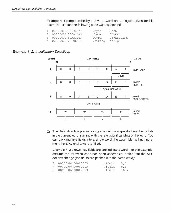
Directives That Initialize Constants
4-8
Example 4–1 compares the .byte, .hword, .word, and .string directives; for thisexample, assume the following code was assembled:
1 00000000 000000AB .byte 0ABh2 00000001 0000CDEF .hword 0CDEFh3 00000002 89ABCDEF .word 089ABCDEFh4 00000003 706C6568 .string ”help”
Example 4–1. Initialization Directives
0 0 0 0 0 0 A B
31 0Contents
.byte 0ABh1
Word Code
0 0 0 0 C D E F .hword0CDEFh
2
1 byte
2 bytes (half word)
8 9 A B C D E F .word089ABCDEFh
3
4
whole word
hp l e
70 6C 65 68 .string”help”
� The .field directive places a single value into a specified number of bitsin the current word, starting with the least significant bits of the word. Youcan pack multiple fields into a single word; the assembler will not incre-ment the SPC until a word is filled.
Example 4–2 shows how fields are packed into a word. For this example,assume the following code has been assembled; notice that the SPCdoesn’t change (the fields are packed into the same word):
6 00000004 00000003 .field 3,47 00000004 00000083 .field 8,58 00000004 00002083 .field 16,7
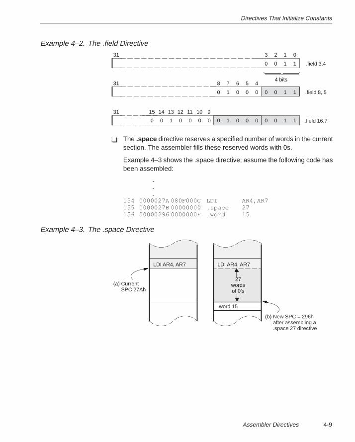
Directives That Initialize Constants
4-9Assembler Directives
Example 4–2. The .field Directive
3 2 1 0
0 0 1 1
4 bits
.field 3,4
31
0 0 1 1 .field 8, 5
31 8 7 6 5 4
0 1 0 0 0
0 0 1 1 .field 16,7
31
0 1 0 0 0
15 14 13 12 11 10 9
0 0 1 0 0 0 0
� The .space directive reserves a specified number of words in the currentsection. The assembler fills these reserved words with 0s.
Example 4–3 shows the .space directive; assume the following code hasbeen assembled:
.
.
.154 0000027A 080F000C LDI AR4,AR7155 0000027B 00000000 .space 27156 00000296 0000000F .word 15
Example 4–3. The .space Directive
(a) CurrentSPC 27Ah
(b) New SPC = 296hafter assembling a.space 27 directive
LDI AR4, AR7 LDI AR4, AR7
.word 15
27wordsof 0’s
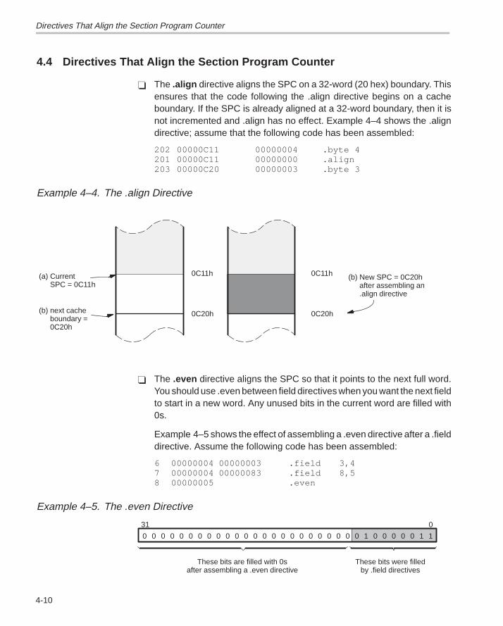
Directives That Align the Section Program Counter
4-10
4.4 Directives That Align the Section Program Counter
� The .align directive aligns the SPC on a 32-word (20 hex) boundary. Thisensures that the code following the .align directive begins on a cacheboundary. If the SPC is already aligned at a 32-word boundary, then it isnot incremented and .align has no effect. Example 4–4 shows the .aligndirective; assume that the following code has been assembled:
202 00000C11 00000004 .byte 4201 00000C11 00000000 .align203 00000C20 00000003 .byte 3
Example 4–4. The .align Directive
(b) next cacheboundary =0C20h
(a) Current SPC = 0C11h
0C11h (b) New SPC = 0C20hafter assembling an.align directive
0C20h
0C11h
0C20h
� The .even directive aligns the SPC so that it points to the next full word.You should use .even between field directives when you want the next fieldto start in a new word. Any unused bits in the current word are filled with0s.
Example 4–5 shows the effect of assembling a .even directive after a .fielddirective. Assume the following code has been assembled:
6 00000004 00000003 .field 3,47 00000004 00000083 .field 8,58 00000005 .even
Example 4–5. The .even Directive
0 0 0 0 0 0 0 0 0 0 0 0 0 0 0 0 0 0 0 0 0 0 0 0 1 0 0 0 0 0 1 1
031
These bits are filled with 0safter assembling a .even directive
These bits were filledby .field directives
Directives That Format the Output Listing
4-11Assembler Directives
4.5 Directives That Format the Output Listing
Several directives format the listing file:
� The source code contains a listing of false conditional blocks that do notgenerate code. The .fclist and .fcnolist directives turn this listing on andoff. You can use the .fclist directive to list false conditional blocks exactlyas they appear in the source code. You can use the .fcnolist directive tolist only the conditional blocks that are actually assembled.
� The .drlist and .drnolist directives turn the printing of directive lines to thelisting file on and off. You can use the .drnolist directive to inhibit theprinting of the following directives:
.asg .eval, .length .mnolist .var
.break .fclist .mmsg .sslist, .width
.emsg .fcnolist .mlist .ssnolist .wmsg
� The .length directive controls the page length of the listing file. You canuse this directive to adjust listings for various output devices.
� The .width directive controls the page width of the listing file. You can usethis directive to adjust listings for various output devices.
� The .list and .nolist directives turn the output listing on and off. You canuse the .nolist directive to stop the assembler from printing selectedsource statements in the listing file. Use the .list directive to turn the listingback on.
� The .mlist and .mnolist directives allow and inhibit macro expansion list-ings.
� The .option directive controls several features in the listing file. This direc-tive has several operands:
B Limits the listing of .byte directives to one line.
H Limits the listing of .hword directives to one line.
F Resets the B, H, L, M, and T options.
L Limits the listing of .long, .int, and .word directives to one line.
M Limits macro expansions to one line.
T Limits the listing of .string directives to one line.
X Produces a cross-reference listing of symbols. (You can also ob-tain a cross-reference listing by invoking the assembler with the -xoption.)
� The .page directive causes a page eject in the output listing.
Directives That Format the Output Listing
4-12
The .sslist and .ssnolist directives allow and inhibit substitution symbolexpansion listing. These directives are useful for debugging substitutionsymbols outside of macros.
The .title directive supplies a title that the assembler prints on the secondline of each page.
Directives That Reference Other Files
4-13Assembler Directives
4.6 Directives That Reference Other Files
These directives supply information for or about other files:
� The .copy and .include directives tell the assembler to begin readingsource statements from another file. When the assembler is finished read-ing the source statements in the copy/include file, it resumes readingsource statements from the current file. The statements read from acopied file are printed in the listing file; the statements read from an in-cluded file are not printed in the listing file.
� The .global directive declares a symbol to be external so that it is availableto other modules at link time. The .global directive does double duty, actingas a .def for defined symbols and as a .ref for undefined symbols. Note thatthe linker will resolve an undefined global symbol only if it is used in theprogram.
� The .def directive identifies a symbol that is defined in the current moduleand can be used by other modules. The assembler puts the symbol in thesymbol table.
� The .ref directive identifies a symbol that is used in the current module butdefined in another module. The assembler marks the symbol as an unde-fined external symbol and puts it in the object symbol table so that thelinker can resolve its definition.
� The .mlib directive supplies the assembler with the name of an archivelibrary that contains macro definitions. When the assembler encountersa macro that is not defined in the current module, it will then be able tosearch for it in the specified macro library.
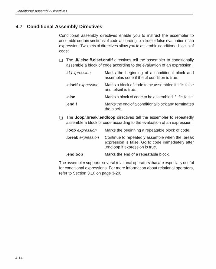
Conditional Assembly Directives
4-14
4.7 Conditional Assembly Directives
Conditional assembly directives enable you to instruct the assembler toassemble certain sections of code according to a true or false evaluation of anexpression. Two sets of directives allow you to assemble conditional blocks ofcode:
� The .if/.elseif/.else/.endif directives tell the assembler to conditionallyassemble a block of code according to the evaluation of an expression.
.if expression Marks the beginning of a conditional block andassembles code if the .if condition is true.
.elseif expression Marks a block of code to be assembled if .if is falseand .elseif is true.
.else Marks a block of code to be assembled if .if is false.
.endif Marks the end of a conditional block and terminatesthe block.
� The .loop/.break/.endloop directives tell the assembler to repeatedlyassemble a block of code according to the evaluation of an expression.
.loop expression Marks the beginning a repeatable block of code.
.break expression Continue to repeatedly assemble when the .breakexpression is false. Go to code immediately after.endloop if expression is true.
.endloop Marks the end of a repeatable block.
The assembler supports several relational operators that are especially usefulfor conditional expressions. For more information about relational operators,refer to Section 3.10 on page 3-20.
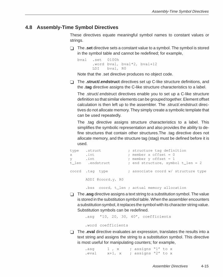
Assembly-Time Symbol Directives
4-15Assembler Directives
4.8 Assembly-Time Symbol DirectivesThese directives equate meaningful symbol names to constant values orstrings.
� The .set directive sets a constant value to a symbol. The symbol is storedin the symbol table and cannot be redefined; for example,
bval .set 0100h.word bval, bval*2, bval+12LDI bval, R0
Note that the .set directive produces no object code.
� The .struct/.endstruct directives set up C-like structure definitions, andthe .tag directive assigns the C-like structure characteristics to a label.
The .struct/.endstruct directives enable you to set up a C-like structuredefinition so that similar elements can be grouped together. Element offsetcalculation is then left up to the assembler. The .struct/.endstruct direc-tives do not allocate memory. They simply create a symbolic template thatcan be used repeatedly.
The .tag directive assigns structure characteristics to a label. Thissimplifies the symbolic representation and also provides the ability to de-fine structures that contain other structures.The .tag directive does notallocate memory, and the structure tag (stag) must be defined before it isused.
type .struct ; structure tag definitionx .int ; member x offset = 0y .int ; member y offset = 1t_len .endstruct ; end structure, symbol t_len = 2
coord .tag type ; associate coord w/ structure type
ADDI @coord.y, R0
.bss coord, t_len ; actual memory allocation
� The .asg directive assigns a text string to a substitution symbol. The valueis stored in the substitution symbol table. When the assembler encountersa substitution symbol, it replaces the symbol with its character string value.Substitution symbols can be redefined.
.asg ”10, 20, 30, 40”, coefficients
.word coefficients
� The .eval directive evaluates an expression, translates the results into atext string and assigns the string to a substitution symbol. This directiveis most useful for manipulating counters; for example,
.asg 1 , x ; assigns “1” to x
.eval x+1, x ; assigns “2” to x
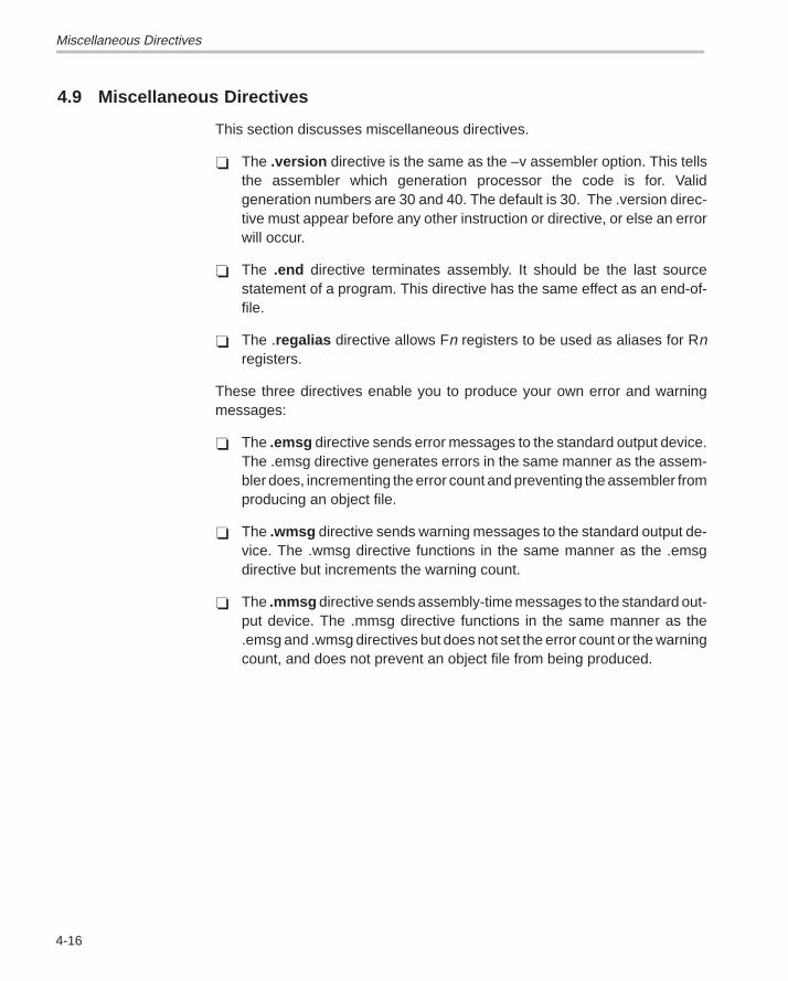
Miscellaneous Directives
4-16
4.9 Miscellaneous Directives
This section discusses miscellaneous directives.
� The .version directive is the same as the –v assembler option. This tellsthe assembler which generation processor the code is for. Validgeneration numbers are 30 and 40. The default is 30. The .version direc-tive must appear before any other instruction or directive, or else an errorwill occur.
� The .end directive terminates assembly. It should be the last sourcestatement of a program. This directive has the same effect as an end-of-file.
� The .regalias directive allows Fn registers to be used as aliases for Rnregisters.
These three directives enable you to produce your own error and warningmessages:
� The .emsg directive sends error messages to the standard output device.The .emsg directive generates errors in the same manner as the assem-bler does, incrementing the error count and preventing the assembler fromproducing an object file.
� The .wmsg directive sends warning messages to the standard output de-vice. The .wmsg directive functions in the same manner as the .emsgdirective but increments the warning count.
� The .mmsg directive sends assembly-time messages to the standard out-put device. The .mmsg directive functions in the same manner as the.emsg and .wmsg directives but does not set the error count or the warningcount, and does not prevent an object file from being produced.
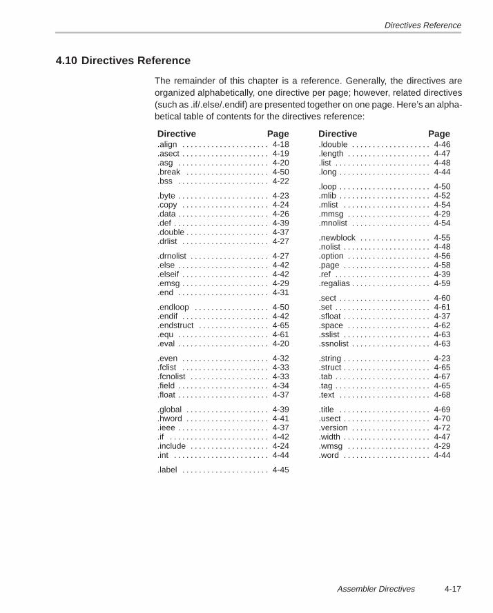
Directives Reference
4-17Assembler Directives
4.10 Directives Reference
The remainder of this chapter is a reference. Generally, the directives areorganized alphabetically, one directive per page; however, related directives(such as .if/.else/.endif) are presented together on one page. Here’s an alpha-betical table of contents for the directives reference:
Directive Page Directive Page.align 4-18. . . . . . . . . . . . . . . . . . . . . .asect 4-19. . . . . . . . . . . . . . . . . . . . . .asg 4-20. . . . . . . . . . . . . . . . . . . . . . .break 4-50. . . . . . . . . . . . . . . . . . . . .bss 4-22. . . . . . . . . . . . . . . . . . . . . .
.byte 4-23. . . . . . . . . . . . . . . . . . . . . .
.copy 4-24. . . . . . . . . . . . . . . . . . . . .
.data 4-26. . . . . . . . . . . . . . . . . . . . . .
.def 4-39. . . . . . . . . . . . . . . . . . . . . . .
.double 4-37. . . . . . . . . . . . . . . . . . . .
.drlist 4-27. . . . . . . . . . . . . . . . . . . . .
.drnolist 4-27. . . . . . . . . . . . . . . . . . .
.else 4-42. . . . . . . . . . . . . . . . . . . . . .
.elseif 4-42. . . . . . . . . . . . . . . . . . . . .
.emsg 4-29. . . . . . . . . . . . . . . . . . . . .
.end 4-31. . . . . . . . . . . . . . . . . . . . . .
.endloop 4-50. . . . . . . . . . . . . . . . . .
.endif 4-42. . . . . . . . . . . . . . . . . . . . .
.endstruct 4-65. . . . . . . . . . . . . . . . .
.equ 4-61. . . . . . . . . . . . . . . . . . . . . .
.eval 4-20. . . . . . . . . . . . . . . . . . . . . .
.even 4-32. . . . . . . . . . . . . . . . . . . . .
.fclist 4-33. . . . . . . . . . . . . . . . . . . . .
.fcnolist 4-33. . . . . . . . . . . . . . . . . . .
.field 4-34. . . . . . . . . . . . . . . . . . . . . .
.float 4-37. . . . . . . . . . . . . . . . . . . . . .
.global 4-39. . . . . . . . . . . . . . . . . . . .
.hword 4-41. . . . . . . . . . . . . . . . . . . .
.ieee 4-37. . . . . . . . . . . . . . . . . . . . . .
.if 4-42. . . . . . . . . . . . . . . . . . . . . . . .
.include 4-24. . . . . . . . . . . . . . . . . . .
.int 4-44. . . . . . . . . . . . . . . . . . . . . . .
.label 4-45. . . . . . . . . . . . . . . . . . . . .
.ldouble 4-46. . . . . . . . . . . . . . . . . . .
.length 4-47. . . . . . . . . . . . . . . . . . . .
.list 4-48. . . . . . . . . . . . . . . . . . . . . . .
.long 4-44. . . . . . . . . . . . . . . . . . . . . .
.loop 4-50. . . . . . . . . . . . . . . . . . . . . .
.mlib 4-52. . . . . . . . . . . . . . . . . . . . . .
.mlist 4-54. . . . . . . . . . . . . . . . . . . . .
.mmsg 4-29. . . . . . . . . . . . . . . . . . . .
.mnolist 4-54. . . . . . . . . . . . . . . . . . .
.newblock 4-55. . . . . . . . . . . . . . . . .
.nolist 4-48. . . . . . . . . . . . . . . . . . . . .
.option 4-56. . . . . . . . . . . . . . . . . . . .
.page 4-58. . . . . . . . . . . . . . . . . . . . .
.ref 4-39. . . . . . . . . . . . . . . . . . . . . . .
.regalias 4-59. . . . . . . . . . . . . . . . . . .
.sect 4-60. . . . . . . . . . . . . . . . . . . . . .
.set 4-61. . . . . . . . . . . . . . . . . . . . . . .
.sfloat 4-37. . . . . . . . . . . . . . . . . . . . .
.space 4-62. . . . . . . . . . . . . . . . . . . .
.sslist 4-63. . . . . . . . . . . . . . . . . . . . .
.ssnolist 4-63. . . . . . . . . . . . . . . . . . .
.string 4-23. . . . . . . . . . . . . . . . . . . . .
.struct 4-65. . . . . . . . . . . . . . . . . . . . .
.tab 4-67. . . . . . . . . . . . . . . . . . . . . . .
.tag 4-65. . . . . . . . . . . . . . . . . . . . . . .
.text 4-68. . . . . . . . . . . . . . . . . . . . . .
.title 4-69. . . . . . . . . . . . . . . . . . . . . .
.usect 4-70. . . . . . . . . . . . . . . . . . . . .
.version 4-72. . . . . . . . . . . . . . . . . . .
.width 4-47. . . . . . . . . . . . . . . . . . . . .
.wmsg 4-29. . . . . . . . . . . . . . . . . . . .
.word 4-44. . . . . . . . . . . . . . . . . . . . .
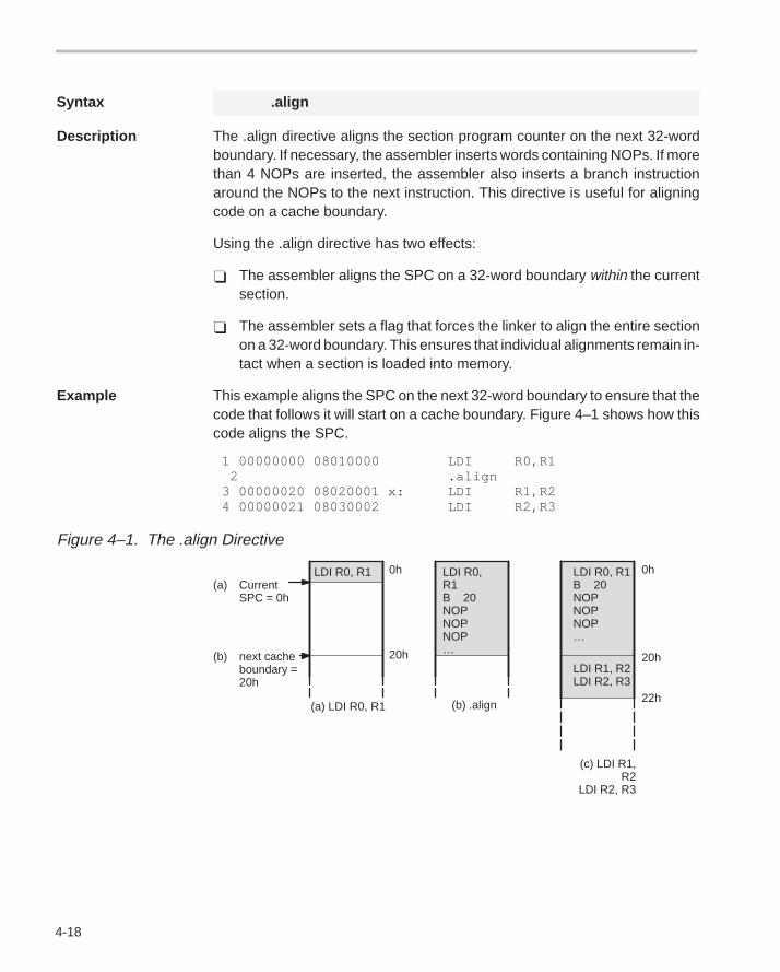
4-18
Syntax .align
Description The .align directive aligns the section program counter on the next 32-wordboundary. If necessary, the assembler inserts words containing NOPs. If morethan 4 NOPs are inserted, the assembler also inserts a branch instructionaround the NOPs to the next instruction. This directive is useful for aligningcode on a cache boundary.
Using the .align directive has two effects:
� The assembler aligns the SPC on a 32-word boundary within the currentsection.
� The assembler sets a flag that forces the linker to align the entire sectionon a 32-word boundary. This ensures that individual alignments remain in-tact when a section is loaded into memory.
Example This example aligns the SPC on the next 32-word boundary to ensure that thecode that follows it will start on a cache boundary. Figure 4–1 shows how thiscode aligns the SPC.
1 00000000 08010000 LDI R0,R1 2 .align 3 00000020 08020001 x: LDI R1,R2 4 00000021 08030002 LDI R2,R3
Figure 4–1. The .align Directive
(a) CurrentSPC = 0h
0h
20h
0h
20h
22h(a) LDI R0, R1 (b) .align
(c) LDI R1,R2
LDI R2, R3
LDI R0, R1 LDI R0,R1B 20NOPNOPNOP…
(b) next cacheboundary =20h
LDI R0, R1B 20NOPNOPNOP…
LDI R1, R2LDI R2, R3
4-19
Syntax .asect ” section name”, address
Description The .asect directive defines a named section whose addresses are absolutewith respect to address. This command is obsolete. Any section can now beloaded and run at two separate addresses using the linker. The commandfunctions as before for compatibility.
section name a required parameter that identifies the name of theabsolute section. It be enclosed in double quotes.
address a required parameter that identifies the section’s absolutestarting address in target memory, which is required the firsttime you assemble into a specific absolute section. If youuse .asect to continue an assembly into an a section thatcontains code, you cannot use the address parameter.
Absolute sections are useful for loading sections of code from off-chip memoryinto faster on-chip memory. In order to use an absolute section, you must knowwhich location you want the section to execute from and specify it as theaddress parameter.
Most sections directives create sections with relocatable addresses. Thestarting SPC value for these sections is always zero; the linker then relocatesthem where appropriate. The starting SPC value for an absolute section,however, is the specified address. The addresses of all code assembled intoan absolute section are offsets from the specified address. The linker doesrelocate sections defined with .asect; however, any labels defined within anabsolute section retain their absolute (runtime) addresses. Thus, referencesto these labels refer to their runtime addresses, even though the section is notinitially loaded at its runtime address.
All labels in an absolute section have absolute addresses. The .label directivecreates labels with relocatable addresses; this allows you to define a symbolthat points to the section’s loadtime location in off-chip memory.
Note that after you define a section with .asect, you can use the .sect directivelater in the program to continue assembling code into the absolute section.
Note: The .asect Directive Is Obsolete
The .asect directive is obsolete because the linker’s SECTIONS directivenow allows separate load and run addresses for any section. The .asectdirective is fully functional to allow compatibility with previous versions of theassembler. For more information, refer to Section 8.7 on page 8-27.
4-20
Syntax .asg [” ]character string[” ], substitution symbol
.eval well-defined expression, substitution symbol
Description The .asg directive assigns character strings to substitution symbols. Substitu-tion symbols are stored in the substitution symbol table.
The .asg directive can be used in many of the same ways as the .set directive,but while .set assigns a constant value (cannot be redefined) to a symbol, .asgassigns a string (can be redefined) to a substitution symbol.
The .eval directive performs arithmetic on substitution symbols. This directiveevaluates the expression and assigns the string value of the result to the sub-stitution symbol. The .eval directive is especially useful as a counter in.loop/.endloop blocks.
character string Is assigned to the substitution symbol by theassembler. The quotation marks are optional. Ifthere are no quotation marks, the assemblerreads characters up to the first comma andremoves leading and trailing blanks. In eithercase, a character string is read and assigned tothe substitution symbol.
substitution symbol Is a required parameter that must be a valid sym-bol name. The substitution symbol may be 32characters long and must begin with a letter.Remaining characters of the symbol can be acombination of alphanumeric characters, under-scores, and dollar signs. When the assemblerencounters a substitution symbol in a sourcestatement, it substitutes the assigned string forthe symbol and rescans the line. In this way, sub-stitution symbols provide a general text replace-ment mechanism.
well-defined expression Is an alphanumeric expression consisting oflegal values that have been previously defined,so that the result is an absolute.
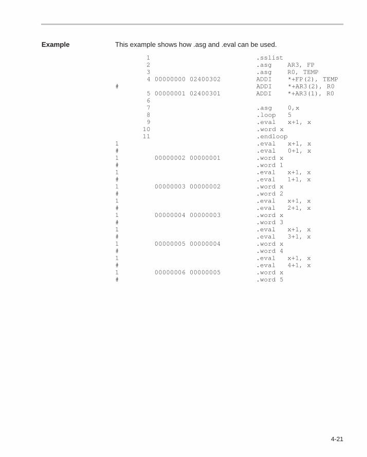
4-21
Example This example shows how .asg and .eval can be used.
1 .sslist 2 .asg AR3, FP 3 .asg R0, TEMP 4 00000000 02400302 ADDI *+FP(2), TEMP# ADDI *+AR3(2), R0 5 00000001 02400301 ADDI *+AR3(1), R0 6 7 .asg 0,x 8 .loop 5 9 .eval x+1, x 10 .word x 11 .endloop1 .eval x+1, x# .eval 0+1, x1 00000002 00000001 .word x# .word 11 .eval x+1, x# .eval 1+1, x1 00000003 00000002 .word x# .word 21 .eval x+1, x# .eval 2+1, x1 00000004 00000003 .word x# .word 31 .eval x+1, x# .eval 3+1, x1 00000005 00000004 .word x# .word 41 .eval x+1, x# .eval 4+1, x1 00000006 00000005 .word x# .word 5
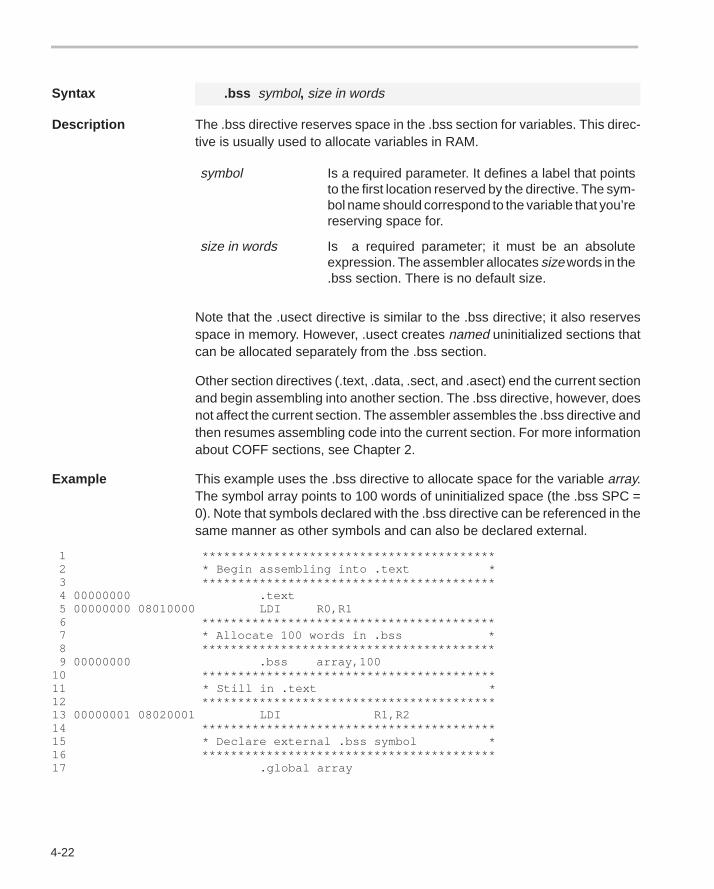
4-22
Syntax .bss symbol, size in words
Description The .bss directive reserves space in the .bss section for variables. This direc-tive is usually used to allocate variables in RAM.
symbol Is a required parameter. It defines a label that pointsto the first location reserved by the directive. The sym-bol name should correspond to the variable that you’rereserving space for.
size in words Is a required parameter; it must be an absoluteexpression. The assembler allocates size words in the.bss section. There is no default size.
Note that the .usect directive is similar to the .bss directive; it also reservesspace in memory. However, .usect creates named uninitialized sections thatcan be allocated separately from the .bss section.
Other section directives (.text, .data, .sect, and .asect) end the current sectionand begin assembling into another section. The .bss directive, however, doesnot affect the current section. The assembler assembles the .bss directive andthen resumes assembling code into the current section. For more informationabout COFF sections, see Chapter 2.
Example This example uses the .bss directive to allocate space for the variable array.The symbol array points to 100 words of uninitialized space (the .bss SPC =0). Note that symbols declared with the .bss directive can be referenced in thesame manner as other symbols and can also be declared external.
1 ***************************************** 2 * Begin assembling into .text * 3 ***************************************** 4 00000000 .text 5 00000000 08010000 LDI R0,R1 6 ***************************************** 7 * Allocate 100 words in .bss * 8 ***************************************** 9 00000000 .bss array,10010 *****************************************11 * Still in .text *12 *****************************************13 00000001 08020001 LDI R1,R214 *****************************************15 * Declare external .bss symbol *16 *****************************************17 .global array
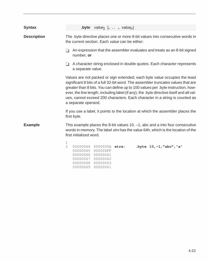
4-23
Syntax .byte value1 [, ... , valuen]
Description The .byte directive places one or more 8-bit values into consecutive words inthe current section. Each value can be either:
� An expression that the assembler evaluates and treats as an 8-bit signednumber, or
� A character string enclosed in double quotes. Each character representsa separate value.
Values are not packed or sign extended; each byte value occupies the leastsignificant 8 bits of a full 32-bit word. The assembler truncates values that aregreater than 8 bits. You can define up to 100 values per .byte instruction, how-ever, the line length, including label (if any), the .byte directive itself and all val-ues, cannot exceed 200 characters. Each character in a string is counted asa separate operand.
If you use a label, it points to the location at which the assembler places thefirst byte.
Example This example places the 8-bit values 10, –1, abc and a into four consecutivewords in memory. The label strx has the value 64h, which is the location of thefirst initialized word.
12 00000064 0000000A strx: .byte 10,–1,”abc”,’a’
00000065 000000FF00000066 0000006100000067 0000006200000068 0000006300000069 00000061
4-24
Syntax .copy [” ]filename[” ]
.include [” ]filename[” ]
Description The .copy and .include directives tell the assembler to read source statementsfrom a different file. The statements that are assembled from a copy file areprinted in the assembly listing. The statements that are assembled from an in-cluded file are not printed in the assembly listing, regardless of the number of.list/.nolist directives that are assembled. The assembler:
1) Stops assembling statements in the current source file,
2) Assembles the statements in the copied/included file, and
3) Resumes assembling statements in the main source file, starting with thestatement that follows the .copy or .include directive.
The filename is a required parameter that names a source file; the filenamemay be enclosed in double quotes. The filename must follow operating systemconventions. You can specify a full pathname (for example, .copyc:\dsp\file1.asm). If you do not specify a full pathname, the assemblersearches for the file in:
1) The directory that contains the current source file.2) Any directories named with the -i assembler option.3) Any directories specified by the environment variable A_DIR.
For more information about the -i option and the environment variable, seeSection 3.5, Naming Alternate Directories for Assembler Input, on page 3-7.
The .copy and .include directives may be nested within a file being copied orincluded. The assembler limits this type of nesting to ten levels; the host oper-ating system may set additional restrictions. The assembler precedes the linenumbers of copied files with a letter code to identify the level of copying. AnA indicates the first copied file, B indicates a second copied file, etc.
Example 1 This example uses the .copy directive to read and assemble source state-ments from other files, then resumes assembling into the current file.
The original file, copy.asm, contains a .copy statement copying the filebyte.asm. When copy.asm assembles, the assembler copies byte.asm into itsplace in the listing (note listing below). The copy file byte.asm contains a .copystatement for a second file, word.asm.
When it encounters the .copy statement for word.asm, the assembler switchesto word.asm to continue copying and assembling. Then the assembler returnsto its place in byte.asm to continue copying and assembling. After completingassembly of byte.asm, the assembler returns to copy.asm to assemble itsremaining statement.
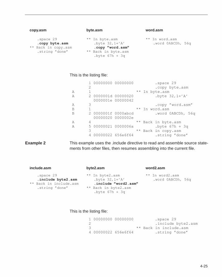
4-25
copy.asm byte.asm word.asm
.space 29
.copy byte.asm** Back in copy.asm
.string ”done”
** In byte.asm.byte 32,1+’A’.copy ”word.asm”
** Back in byte.asm.byte 67h + 3q
** In word.asm.word 0ABCDh, 56q
This is the listing file:
1 00000000 00000000 .space 29 2 .copy byte.asm A 1 ** In byte.asm A 2 0000001d 00000020 .byte 32,1+’A’ 0000001e 00000042 A 3 .copy ”word.asm” B 1 ** In word.asm B 2 0000001f 0000abcd .word 0ABCDh, 56q 00000020 0000002e A 4 ** Back in byte.asm A 5 00000021 0000006a .byte 67h + 3q 3 ** Back in copy.asm 4 00000022 656e6f64 .string ”done”
Example 2 This example uses the .include directive to read and assemble source state-ments from other files, then resumes assembling into the current file.
include.asm byte2.asm word2.asm
.space 29
.include byte2.asm** Back in include.asm
.string ”done”
** In byte2.asm.byte 32,1+’A’.include ”word2.asm”
** Back in byte2.asm.byte 67h + 3q
** In word2.asm.word 0ABCDh, 56q
This is the listing file:
1 00000000 00000000 .space 29 2 .include byte2.asm 3 ** Back in include.asm 4 00000022 656e6f64 .string ”done”
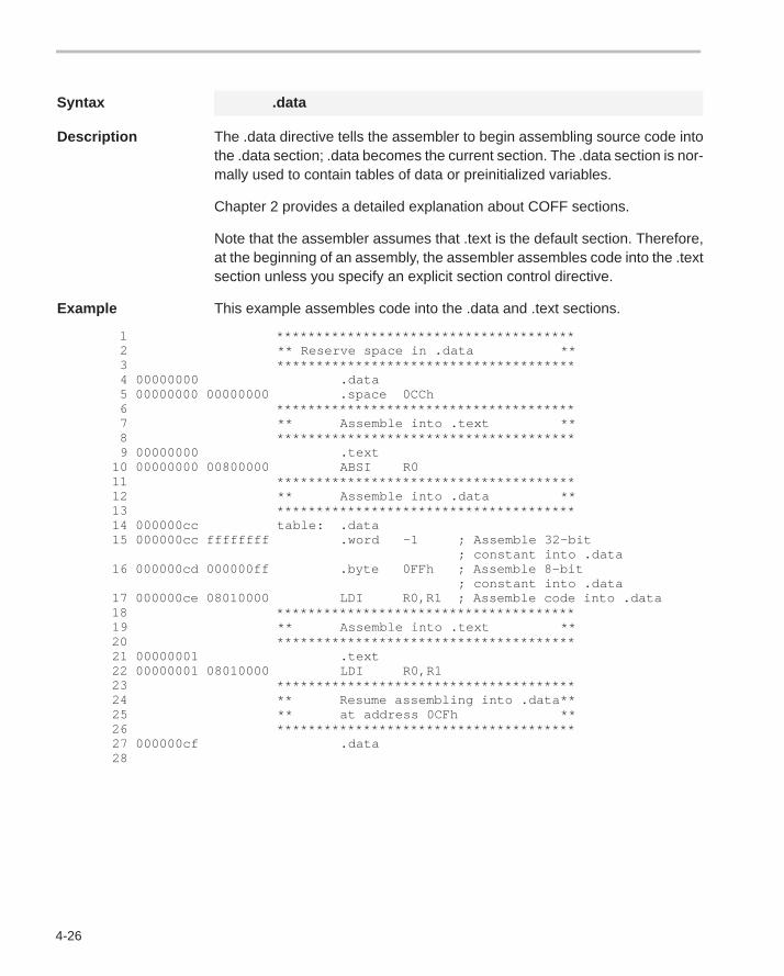
4-26
Syntax .data
Description The .data directive tells the assembler to begin assembling source code intothe .data section; .data becomes the current section. The .data section is nor-mally used to contain tables of data or preinitialized variables.
Chapter 2 provides a detailed explanation about COFF sections.
Note that the assembler assumes that .text is the default section. Therefore,at the beginning of an assembly, the assembler assembles code into the .textsection unless you specify an explicit section control directive.
Example This example assembles code into the .data and .text sections.
1 ************************************** 2 ** Reserve space in .data ** 3 ************************************** 4 00000000 .data 5 00000000 00000000 .space 0CCh 6 ************************************** 7 ** Assemble into .text ** 8 ************************************** 9 00000000 .text 10 00000000 00800000 ABSI R0 11 ************************************** 12 ** Assemble into .data ** 13 ************************************** 14 000000cc table: .data 15 000000cc ffffffff .word –1 ; Assemble 32–bit ; constant into .data 16 000000cd 000000ff .byte 0FFh ; Assemble 8–bit ; constant into .data 17 000000ce 08010000 LDI R0,R1 ; Assemble code into .data 18 ************************************** 19 ** Assemble into .text ** 20 ************************************** 21 00000001 .text 22 00000001 08010000 LDI R0,R1 23 ************************************** 24 ** Resume assembling into .data** 25 ** at address 0CFh ** 26 ************************************** 27 000000cf .data 28
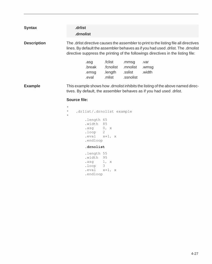
4-27
Syntax .drlist
.drnolist
Description The .drlist directive causes the assembler to print to the listing file all directiveslines. By default the assembler behaves as if you had used .drlist. The .drnolistdirective suppress the printing of the followings directives in the listing file:
.asg .fclist .mmsg .var
.break .fcnolist .mnolist .wmsg
.emsg .length .sslist .width
.eval .mlist .ssnolist
Example This example shows how .drnolist inhibits the listing of the above named direc-tives. By default, the assembler behaves as if you had used .drlist.
Source file:
** .drlist/.drnolist example* .length 65 .width 85 .asg 0, x .loop 2 .eval x+1, x .endloop
.drnolist
.length 55 .width 95 .asg 1, x .loop 3 .eval x+1, x .endloop
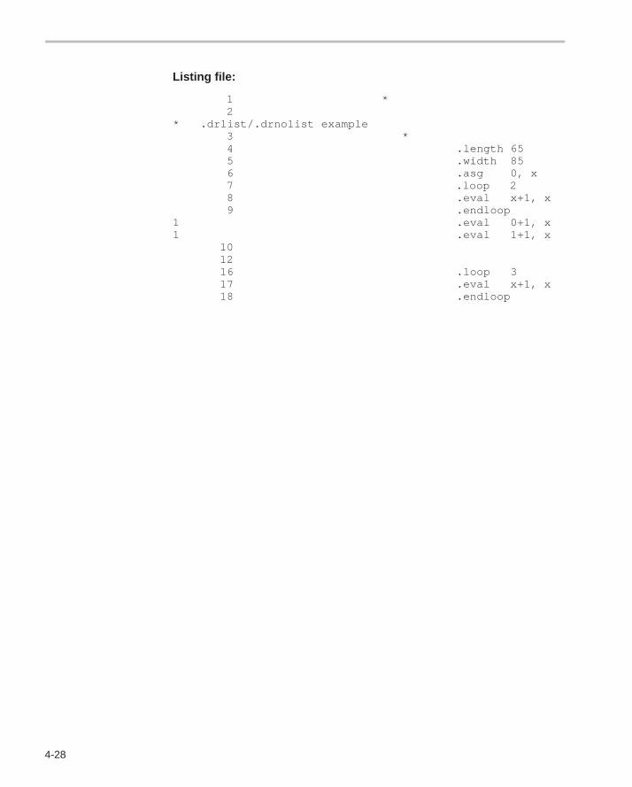
4-28
Listing file:
1 * 2 * .drlist/.drnolist example 3 * 4 .length 65 5 .width 85 6 .asg 0, x 7 .loop 2 8 .eval x+1, x 9 .endloop1 .eval 0+1, x1 .eval 1+1, x 10 12 16 .loop 3 17 .eval x+1, x 18 .endloop
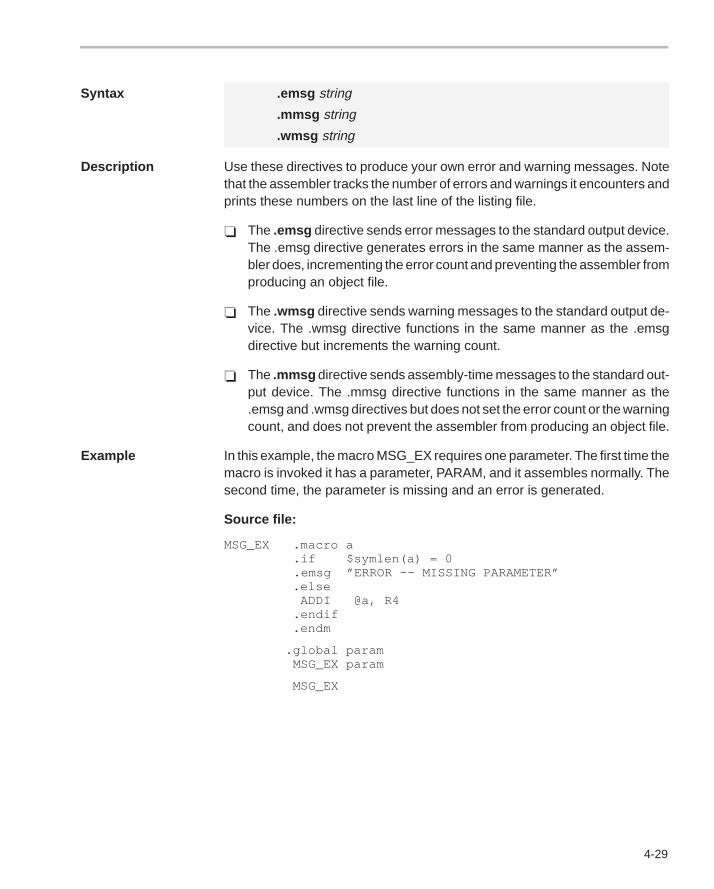
4-29
Syntax .emsg string
.mmsg string
.wmsg string
Description Use these directives to produce your own error and warning messages. Notethat the assembler tracks the number of errors and warnings it encounters andprints these numbers on the last line of the listing file.
� The .emsg directive sends error messages to the standard output device.The .emsg directive generates errors in the same manner as the assem-bler does, incrementing the error count and preventing the assembler fromproducing an object file.
� The .wmsg directive sends warning messages to the standard output de-vice. The .wmsg directive functions in the same manner as the .emsgdirective but increments the warning count.
� The .mmsg directive sends assembly-time messages to the standard out-put device. The .mmsg directive functions in the same manner as the.emsg and .wmsg directives but does not set the error count or the warningcount, and does not prevent the assembler from producing an object file.
Example In this example, the macro MSG_EX requires one parameter. The first time themacro is invoked it has a parameter, PARAM, and it assembles normally. Thesecond time, the parameter is missing and an error is generated.
Source file:
MSG_EX .macro a .if $symlen(a) = 0 .emsg ”ERROR –– MISSING PARAMETER” .else ADDI @a, R4 .endif .endm
.global param MSG_EX param
MSG_EX
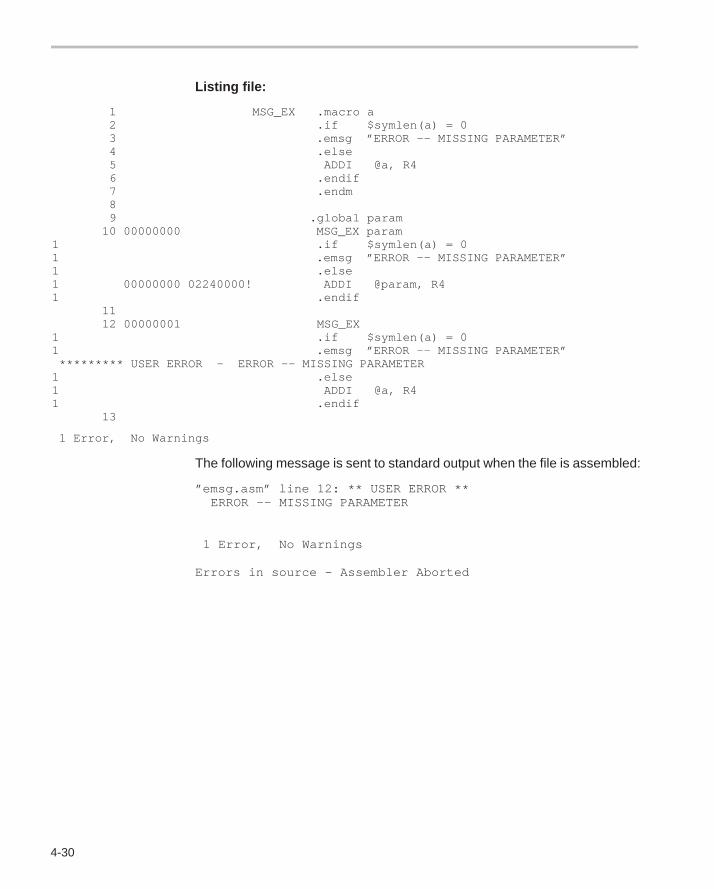
4-30
Listing file:
1 MSG_EX .macro a 2 .if $symlen(a) = 0 3 .emsg ”ERROR –– MISSING PARAMETER” 4 .else 5 ADDI @a, R4 6 .endif 7 .endm 8 9 .global param 10 00000000 MSG_EX param1 .if $symlen(a) = 01 .emsg ”ERROR –– MISSING PARAMETER”1 .else1 00000000 02240000! ADDI @param, R41 .endif 11 12 00000001 MSG_EX1 .if $symlen(a) = 01 .emsg ”ERROR –– MISSING PARAMETER” ********* USER ERROR – ERROR –– MISSING PARAMETER1 .else1 ADDI @a, R41 .endif 13
1 Error, No Warnings
The following message is sent to standard output when the file is assembled:
”emsg.asm” line 12: ** USER ERROR ** ERROR –– MISSING PARAMETER
1 Error, No Warnings
Errors in source – Assembler Aborted
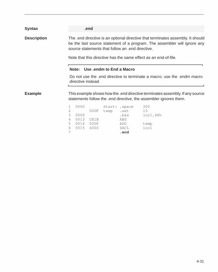
4-31
Syntax .end
Description The .end directive is an optional directive that terminates assembly. It shouldbe the last source statement of a program. The assembler will ignore anysource statements that follow an .end directive.
Note that this directive has the same effect as an end-of-file.
Note: Use .endm to End a Macro
Do not use the .end directive to terminate a macro; use the .endm macrodirective instead.
Example This example shows how the .end directive terminates assembly. If any sourcestatements follow the .end directive, the assembler ignores them.
1 0000 Start: .space 3002 000F temp .set 153 0000 .bss loc1,48h4 0013 CE1B ABS5 0014 000F ADD temp6 0015 6000 SACL loc17 .end
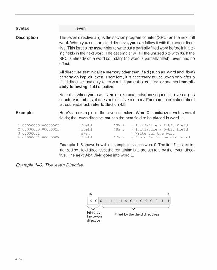
4-32
Syntax .even
Description The .even directive aligns the section program counter (SPC) on the next fullword. When you use the .field directive, you can follow it with the .even direc-tive. This forces the assembler to write out a partially filled word before initializ-ing fields in the next word. The assembler will fill the unused bits with 0s. If theSPC is already on a word boundary (no word is partially filled), .even has noeffect.
All directives that initialize memory other than .field (such as .word and .float)perform an implicit .even. Therefore, it is necessary to use .even only after a.field directive, and only when word alignment is required for another immedi-ately following .field directive.
Note that when you use .even in a .struct/.endstruct sequence, .even alignsstructure members; it does not initialize memory. For more information about.struct/.endstruct, refer to Section 4.8.
Example Here’s an example of the .even directive. Word 0 is initialized with severalfields; the .even directive causes the next field to be placed in word 1.
1 00000000 00000003 .field 03h,2 ; Initialize a 2–bit field 2 00000000 0000002f .field 0Bh,5 ; Initialize a 5–bit field 3 00000001 .even ; Write out the word 4 00000001 00000007 .field 07h,3 ; field is in the next word
Example 4–6 shows how this example initializes word 0. The first 7 bits are in-itialized by .field directives; the remaining bits are set to 0 by the .even direc-tive. The next 3-bit .field goes into word 1.
Example 4–6. The .even Directive
0 1 1 1 1 0 0 1 0 0 0 0 1 10 0
15 0
Filled by the .field directivesFilled bythe .evendirective
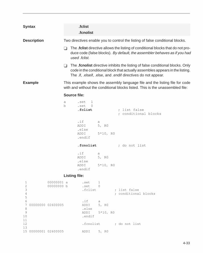
4-33
Syntax .fclist
.fcnolist
Description Two directives enable you to control the listing of false conditional blocks.
� The .fclist directive allows the listing of conditional blocks that do not pro-duce code (false blocks). By default, the assembler behaves as if you hadused .fclist.
� The .fcnolist directive inhibits the listing of false conditional blocks. Onlycode in the conditional block that actually assembles appears in the listing.The .if, .elseif, .else, and .endif directives do not appear.
Example This example shows the assembly language file and the listing file for codewith and without the conditional blocks listed. This is the unassembled file:
Source file:
a .set 1b .set 0
.fclist ; list false ; conditional blocks
.if aADDI 5, R0.elseADDI 5*10, R0.endif
.fcnolist ; do not list
.if aADDI 5, R0.elseADDI 5*10, R0.endif
Listing file:
1 00000001 a .set 1 2 00000000 b .set 0 3 .fclist ; list false 4 ; conditional blocks 5 6 .if a 7 00000000 02600005 ADDI 5, R0 8 .else 9 ADDI 5*10, R010 .endif11 12 .fcnolist ; do not list 13 15 00000001 02600005 ADDI 5, R0
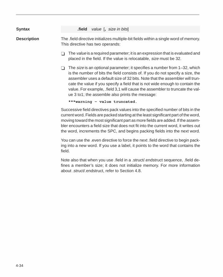
4-34
Syntax .field value [, size in bits]
Description The .field directive initializes multiple-bit fields within a single word of memory.This directive has two operands:
� The value is a required parameter; it is an expression that is evaluated andplaced in the field. If the value is relocatable, size must be 32.
� The size is an optional parameter; it specifies a number from 1–32, whichis the number of bits the field consists of. If you do not specify a size, theassembler uses a default size of 32 bits. Note that the assembler will trun-cate the value if you specify a field that is not wide enough to contain thevalue. For example, .field 3,1 will cause the assembler to truncate the val-ue 3 to1; the assemble also prints the message:
***warning – value truncated .
Successive field directives pack values into the specified number of bits in thecurrent word. Fields are packed starting at the least significant part of the word,moving toward the most significant part as more fields are added. If the assem-bler encounters a field size that does not fit into the current word, it writes outthe word, increments the SPC, and begins packing fields into the next word.
You can use the .even directive to force the next .field directive to begin pack-ing into a new word. If you use a label, it points to the word that contains thefield.
Note also that when you use .field in a .struct/.endstruct sequence, .field de-fines a member’s size; it does not initialize memory. For more informationabout .struct/.endstruct, refer to Section 4.8.
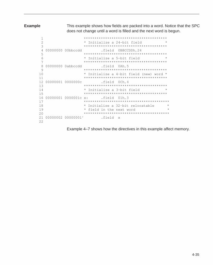
4-35
Example This example shows how fields are packed into a word. Notice that the SPCdoes not change until a word is filled and the next word is begun.
1 *************************************** 2 * Initialize a 24–bit field * 3 *************************************** 4 00000000 00bbccdd .field 0BBCCDDh,24 5 *************************************** 6 * Initialize a 5–bit field * 7 *************************************** 8 00000000 0abbccdd .field 0Ah,5 9 *************************************** 10 * Initialize a 4–bit field (new) word * 11 *************************************** 12 00000001 0000000c .field 0Ch,4 13 *************************************** 14 * Initialize a 3–bit field * 15 *************************************** 16 00000001 0000001c x: .field 01h,3 17 **************************************** 18 * Initialize a 32–bit relocatable * 19 * field in the next word * 20 **************************************** 21 00000002 00000001’ .field x 22
Example 4–7 shows how the directives in this example affect memory.
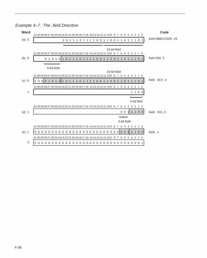
4-36
Example 4–7. The .field Directive
0 0 0 0 0 0 0 0 0 0 0 0 0 0 0 1
24-bit field
15 14 13 12 11 10 9 8 7 6 5 4 3 2 1 0Word Code
(a) 0
(b) 0
(c) 0
(e) 1
2
.field 0BBCCDDh, 24
.field 0Ch, 4
.field x
1 1 0 0 1 1 0 0 1 1 0 1 1 1 0 11 0 1 1 1 0 1 1
31 30 29 28 27 26 25 24 23 22 21 20 19 18 17 16
5-bit field
15 14 13 12 11 10 9 8 7 6 5 4 3 2 1 0
1 1 0 0 1 1 0 0 1 1 0 1 1 1 0 10 1 0 1 0 1 0 1 1 1 0 1 1
31 30 29 28 27 26 25 24 23 22 21 20 19 18 17 16
.field 0Ah, 5
24-bit field15 14 13 12 11 10 9 8 7 6 5 4 3 2 1 0
1 1 0 0 1 1 0 0 1 1 0 1 1 1 0 10 0 0 0 1 0 1 0 1 0 1 1 1 0 1 1
31 30 29 28 27 26 25 24 23 22 21 20 19 18 17 16
1
15 14 13 12 11 10 9 8 7 6 5 4 3 2 1 0
1 1 0 0
31 30 29 28 27 26 25 24 23 22 21 20 19 18 17 16
4-bit field
15 14 13 12 11 10 9 8 7 6 5 4 3 2 1 031 30 29 28 27 26 25 24 23 22 21 20 19 18 17 16
0 0 0 0 0 0 0 0 0 0 0 0 0 0 0 0
15 14 13 12 11 10 9 8 7 6 5 4 3 2 1 031 30 29 28 27 26 25 24 23 22 21 20 19 18 17 16
0 0 0 0 0 0 0 0 0 0 0 0 0 0 0 0
(d) 1 .field 01h, 3
15 14 13 12 11 10 9 8 7 6 5 4 3 2 1 0
0 0 1 1 1 0 0
31 30 29 28 27 26 25 24 23 22 21 20 19 18 17 16
3-bit field
0 0 0 0 0 0 0 0 0 0 0 1 1 1 0 0
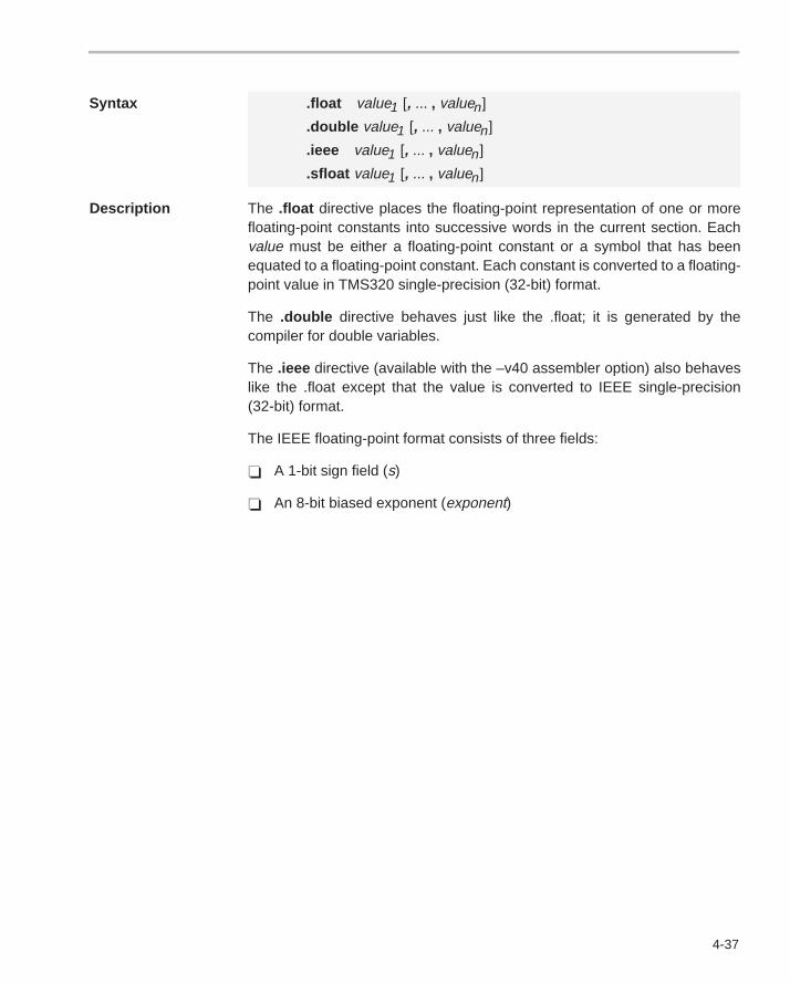
4-37
Syntax .float value1 [, ... , valuen]
.double value1 [, ... , valuen]
.ieee value1 [, ... , valuen]
.sfloat value1 [, ... , valuen]
Description The .float directive places the floating-point representation of one or morefloating-point constants into successive words in the current section. Eachvalue must be either a floating-point constant or a symbol that has beenequated to a floating-point constant. Each constant is converted to a floating-point value in TMS320 single-precision (32-bit) format.
The .double directive behaves just like the .float; it is generated by thecompiler for double variables.
The .ieee directive (available with the –v40 assembler option) also behaveslike the .float except that the value is converted to IEEE single-precision(32-bit) format.
The IEEE floating-point format consists of three fields:
� A 1-bit sign field (s)
� An 8-bit biased exponent (exponent)
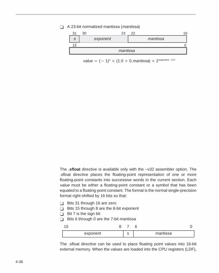
4-38
� A 23-bit normalized mantissa (mantissa)
31 30 23 22 16
15 0
s exponent mantissa
mantissa
value� (� 1)s� (1.0� 0.mantissa)� 2exponent�127
The .sfloat directive is available only with the –v32 assembler option. The.sfloat directive places the floating-point representation of one or morefloating-point constants into successive words in the current section. Eachvalue must be either a floating-point constant or a symbol that has beenequated to a floating-point constant. The format is the normal single-precisionformat right-shifted by 16 bits so that:
� Bits 31 through 16 are zero� Bits 15 through 8 are the 8-bit exponent� Bit 7 is the sign bit� Bits 6 through 0 are the 7-bit mantissa
15 8 7 6 0
exponent s mantissa
The .sfloat directive can be used to place floating point values into 16-bitexternal memory. When the values are loaded into the CPU registers (LDF),
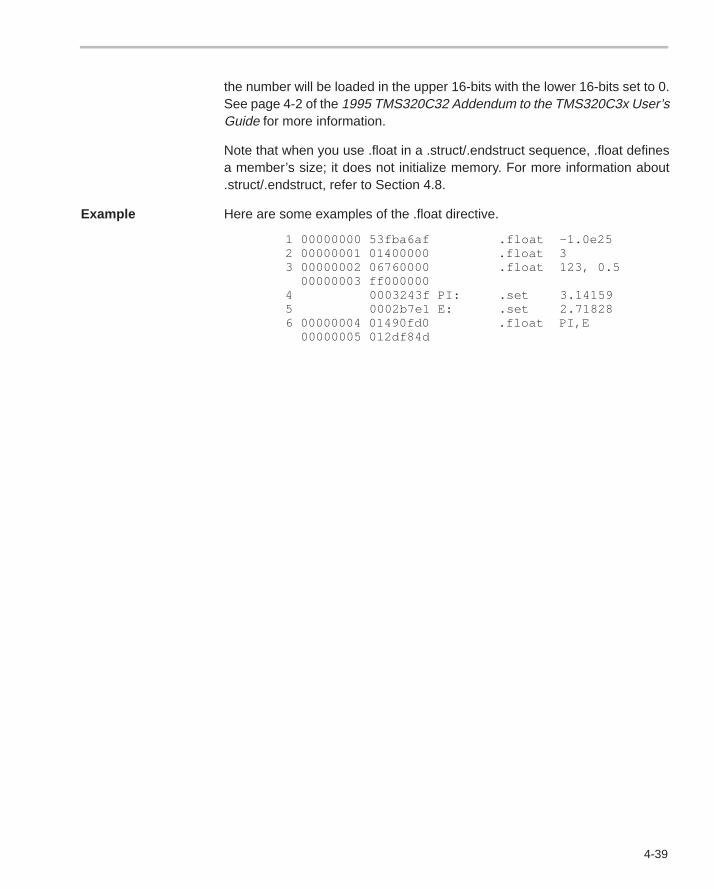
4-39
the number will be loaded in the upper 16-bits with the lower 16-bits set to 0.See page 4-2 of the 1995 TMS320C32 Addendum to the TMS320C3x User’sGuide for more information.
Note that when you use .float in a .struct/.endstruct sequence, .float definesa member’s size; it does not initialize memory. For more information about.struct/.endstruct, refer to Section 4.8.
Example Here are some examples of the .float directive.
1 00000000 53fba6af .float –1.0e25 2 00000001 01400000 .float 3 3 00000002 06760000 .float 123, 0.5 00000003 ff000000 4 0003243f PI: .set 3.14159 5 0002b7e1 E: .set 2.71828 6 00000004 01490fd0 .float PI,E 00000005 012df84d
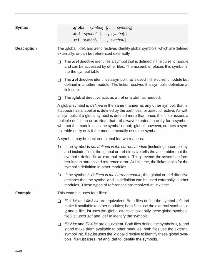
4-40
Syntax .global symbol1 [, ... , symboln]
.def symbol1 [, ... , symboln]
.ref symbol1 [, ... , symboln]
Description The .global, .def, and .ref directives identify global symbols, which are definedexternally, or can be referenced externally.
� The .def directive identifies a symbol that is defined in the current moduleand can be accessed by other files. The assembler places this symbol inthe the symbol table.
� The .ref directive identifies a symbol that is used in the current module butdefined in another module. The linker resolves this symbol’s definition atlink time.
� The .global directive acts as a .ref or a .def, as needed.
A global symbol is defined in the same manner as any other symbol; that is,it appears as a label or is defined by the .set, .bss, or .usect directive. As withall symbols, if a global symbol is defined more than once, the linker issues amultiple-definition error. Note that .ref always creates an entry for a symbol,whether the module uses the symbol or not; .global, however, creates a sym-bol table entry only if the module actually uses the symbol.
A symbol may be declared global for two reasons:
1) If the symbol is not defined in the current module (including macro, .copy,and include files), the .global or .ref directive tells the assembler that thesymbol is defined in an external module. This prevents the assembler fromissuing an unresolved reference error. At link time, the linker looks for thesymbol’s definition in other modules.
2) If the symbol is defined in the current module, the .global or .def directivedeclares that the symbol and its definition can be used externally in othermodules. These types of references are resolved at link time.
Example This example uses four files:
� file1.lst and file3.lst are equivalent. Both files define the symbol Init andmake it available to other modules; both files use the external symbols x,y, and z. file1.lst uses the .global directive to identify these global symbols;file3.lst uses .ref and .def to identify the symbols.
� file2.lst and file4.lst are equivalent. Both files define the symbols x, y, andz and make them available to other modules; both files use the externalsymbol Init. file2.lst uses the .global directive to identify these global sym-bols; file4.lst uses .ref and .def to identify the symbols.
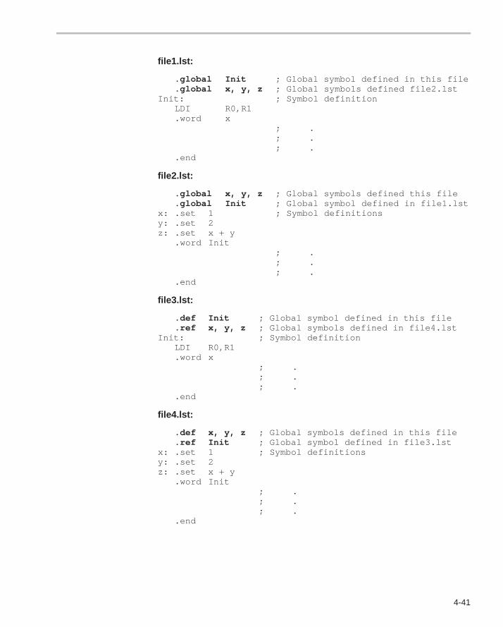
4-41
file1.lst:
.global Init ; Global symbol defined in this file
.global x, y, z ; Global symbols defined file2.lstInit: ; Symbol definition
LDI R0,R1.word x
; .; .; .
.end
file2.lst:
.global x, y, z ; Global symbols defined this file
.global Init ; Global symbol defined in file1.lstx: .set 1 ; Symbol definitionsy: .set 2z: .set x + y
.word Init; .; .; .
.end
file3.lst:
.def Init ; Global symbol defined in this file
.ref x, y, z ; Global symbols defined in file4.lstInit: ; Symbol definition
LDI R0,R1.word x
; .; .; .
.end
file4.lst:
.def x, y, z ; Global symbols defined in this file
.ref Init ; Global symbol defined in file3.lstx: .set 1 ; Symbol definitionsy: .set 2z: .set x + y
.word Init; .; .; .
.end
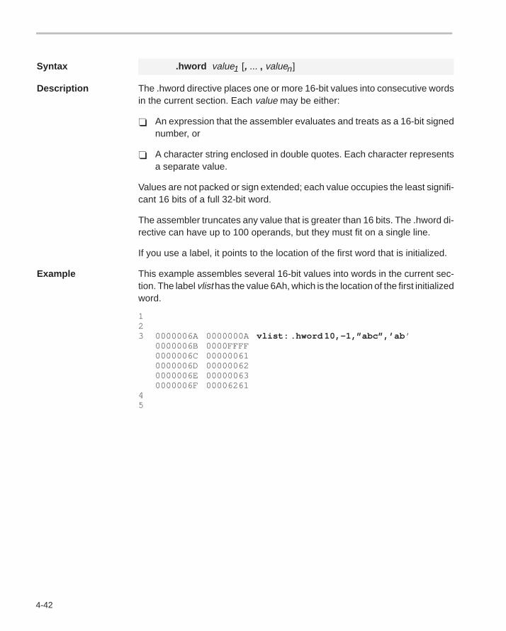
4-42
Syntax .hword value1 [, ... , valuen]
Description The .hword directive places one or more 16-bit values into consecutive wordsin the current section. Each value may be either:
� An expression that the assembler evaluates and treats as a 16-bit signednumber, or
� A character string enclosed in double quotes. Each character representsa separate value.
Values are not packed or sign extended; each value occupies the least signifi-cant 16 bits of a full 32-bit word.
The assembler truncates any value that is greater than 16 bits. The .hword di-rective can have up to 100 operands, but they must fit on a single line.
If you use a label, it points to the location of the first word that is initialized.
Example This example assembles several 16-bit values into words in the current sec-tion. The label vlist has the value 6Ah, which is the location of the first initializedword.
123 0000006A 0000000A vlist: .hword 10,–1,”abc”,’ab ’
0000006B 0000FFFF0000006C 000000610000006D 000000620000006E 000000630000006F 00006261
45
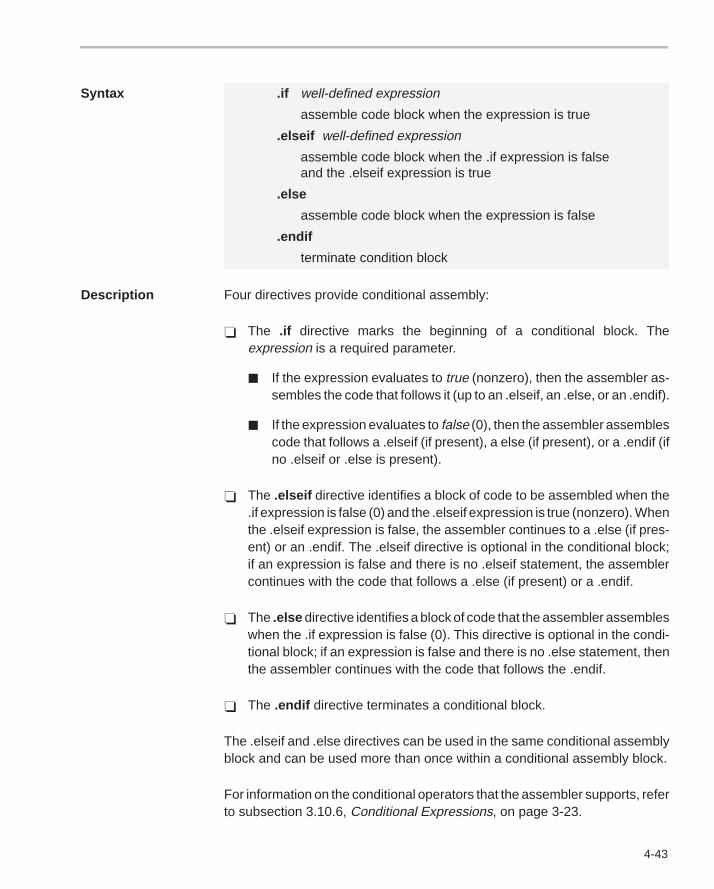
4-43
Syntax .if well-defined expression
assemble code block when the expression is true
.elseif well-defined expression
assemble code block when the .if expression is falseand the .elseif expression is true
.else
assemble code block when the expression is false
.endif
terminate condition block
Description Four directives provide conditional assembly:
� The .if directive marks the beginning of a conditional block. Theexpression is a required parameter.
� If the expression evaluates to true (nonzero), then the assembler as-sembles the code that follows it (up to an .elseif, an .else, or an .endif).
� If the expression evaluates to false (0), then the assembler assemblescode that follows a .elseif (if present), a else (if present), or a .endif (ifno .elseif or .else is present).
� The .elseif directive identifies a block of code to be assembled when the.if expression is false (0) and the .elseif expression is true (nonzero). Whenthe .elseif expression is false, the assembler continues to a .else (if pres-ent) or an .endif. The .elseif directive is optional in the conditional block;if an expression is false and there is no .elseif statement, the assemblercontinues with the code that follows a .else (if present) or a .endif.
� The .else directive identifies a block of code that the assembler assembleswhen the .if expression is false (0). This directive is optional in the condi-tional block; if an expression is false and there is no .else statement, thenthe assembler continues with the code that follows the .endif.
� The .endif directive terminates a conditional block.
The .elseif and .else directives can be used in the same conditional assemblyblock and can be used more than once within a conditional assembly block.
For information on the conditional operators that the assembler supports, referto subsection 3.10.6, Conditional Expressions, on page 3-23.
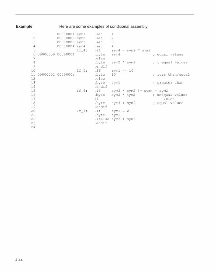
4-44
Example Here are some examples of conditional assembly:
1 00000001 sym1 .set 1 2 00000002 sym2 .set 2 3 00000003 sym3 .set 3 4 00000004 sym4 .set 4 5 If_4: .if sym4 = sym2 * sym2 6 00000000 00000004 .byte sym4 ; equal values 7 .else 8 .byte sym2 * sym2 ; unequal values 9 .endif 10 If_5: .if sym1 <= 10 11 00000001 0000000a .byte 10 ; less than/equal 12 .else 13 .byte sym1 ; greater than 14 .endif 15 If_6: .if sym3 * sym2 != sym4 + sym2 16 .byte sym3 * sym2 ; unequal values 17 17 .else 18 .byte sym4 + sym2 ; equal values 19 .endif 20 If_7: .if sym1 = 2 21 .byte sym1 22 .ifelse sym2 + sym3 23 .endif 24
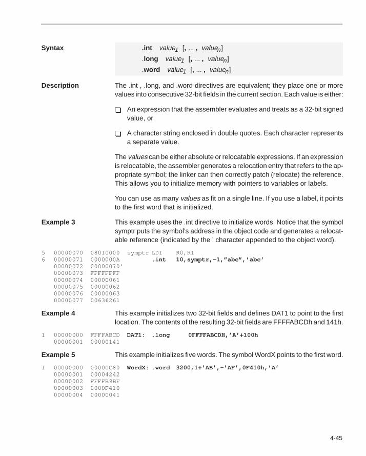
4-45
Syntax .int value1 [, ... , valuen]
.long value1 [, ... , valuen]
.word value1 [, ... , valuen]
Description The .int , .long, and .word directives are equivalent; they place one or morevalues into consecutive 32-bit fields in the current section. Each value is either:
� An expression that the assembler evaluates and treats as a 32-bit signedvalue, or
� A character string enclosed in double quotes. Each character representsa separate value.
The values can be either absolute or relocatable expressions. If an expressionis relocatable, the assembler generates a relocation entry that refers to the ap-propriate symbol; the linker can then correctly patch (relocate) the reference.This allows you to initialize memory with pointers to variables or labels.
You can use as many values as fit on a single line. If you use a label, it pointsto the first word that is initialized.
Example 3 This example uses the .int directive to initialize words. Notice that the symbolsymptr puts the symbol’s address in the object code and generates a relocat-able reference (indicated by the ’ character appended to the object word).
5 00000070 08010000 symptr LDI R0,R16 00000071 0000000A .int 10,symptr,–1,”abc”,’abc’
00000072 00000070’00000073 FFFFFFFF00000074 0000006100000075 0000006200000076 0000006300000077 00636261
Example 4 This example initializes two 32-bit fields and defines DAT1 to point to the firstlocation. The contents of the resulting 32-bit fields are FFFFABCDh and 141h.
1 00000000 FFFFABCD DAT1: .long 0FFFFABCDH,’A’+100h00000001 00000141
Example 5 This example initializes five words. The symbol WordX points to the first word.
1 00000000 00000C80 WordX: .word 3200,1+’AB’,–’AF’,0F410h,’A’00000001 0000424200000002 FFFFB9BF00000003 0000F41000000004 00000041
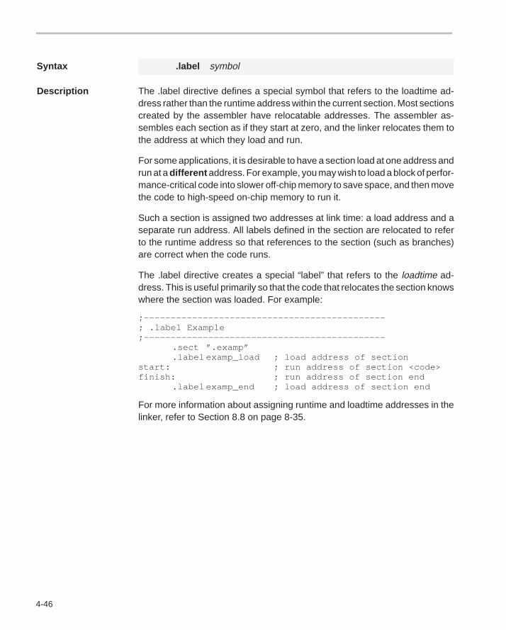
4-46
Syntax .label symbol
Description The .label directive defines a special symbol that refers to the loadtime ad-dress rather than the runtime address within the current section. Most sectionscreated by the assembler have relocatable addresses. The assembler as-sembles each section as if they start at zero, and the linker relocates them tothe address at which they load and run.
For some applications, it is desirable to have a section load at one address andrun at a different address. For example, you may wish to load a block of perfor-mance-critical code into slower off-chip memory to save space, and then movethe code to high-speed on-chip memory to run it.
Such a section is assigned two addresses at link time: a load address and aseparate run address. All labels defined in the section are relocated to referto the runtime address so that references to the section (such as branches)are correct when the code runs.
The .label directive creates a special “label” that refers to the loadtime ad-dress. This is useful primarily so that the code that relocates the section knowswhere the section was loaded. For example:
;–––––––––––––––––––––––––––––––––––––––––––––; .label Example;–––––––––––––––––––––––––––––––––––––––––––––
.sect ”.examp”
.label examp_load ; load address of sectionstart: ; run address of section <code>finish: ; run address of section end
.label examp_end ; load address of section end
For more information about assigning runtime and loadtime addresses in thelinker, refer to Section 8.8 on page 8-35.
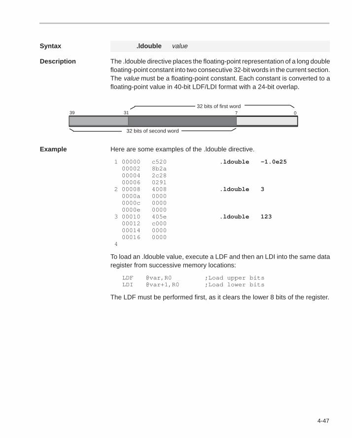
4-47
Syntax .ldouble value
Description The .ldouble directive places the floating-point representation of a long doublefloating-point constant into two consecutive 32-bit words in the current section.The value must be a floating-point constant. Each constant is converted to afloating-point value in 40-bit LDF/LDI format with a 24-bit overlap.
32 bits of first word39 31 7 0
32 bits of second word
Example Here are some examples of the .ldouble directive.
1 00000 c520 .ldouble –1.0e25 00002 8b2a 00004 2c28 00006 0291 2 00008 4008 .ldouble 3 0000a 0000 0000c 0000 0000e 0000 3 00010 405e .ldouble 123 00012 c000 00014 0000 00016 0000 4
To load an .ldouble value, execute a LDF and then an LDI into the same dataregister from successive memory locations:
LDF @var,R0 ;Load upper bitsLDI @var+1,R0 ;Load lower bits
The LDF must be performed first, as it clears the lower 8 bits of the register.
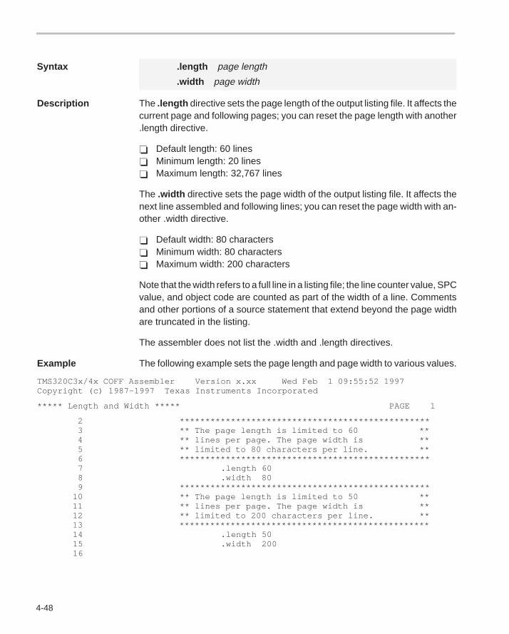
4-48
Syntax .length page length
.width page width
Description The .length directive sets the page length of the output listing file. It affects thecurrent page and following pages; you can reset the page length with another.length directive.
� Default length: 60 lines� Minimum length: 20 lines� Maximum length: 32,767 lines
The .width directive sets the page width of the output listing file. It affects thenext line assembled and following lines; you can reset the page width with an-other .width directive.
� Default width: 80 characters� Minimum width: 80 characters� Maximum width: 200 characters
Note that the width refers to a full line in a listing file; the line counter value, SPCvalue, and object code are counted as part of the width of a line. Commentsand other portions of a source statement that extend beyond the page widthare truncated in the listing.
The assembler does not list the .width and .length directives.
Example The following example sets the page length and page width to various values.
TMS320C3x/4x COFF Assembler Version x.xx Wed Feb 1 09:55:52 1997Copyright (c) 1987–1997 Texas Instruments Incorporated
***** Length and Width ***** PAGE 1
2 ************************************************* 3 ** The page length is limited to 60 ** 4 ** lines per page. The page width is ** 5 ** limited to 80 characters per line. ** 6 ************************************************* 7 .length 60 8 .width 80 9 ************************************************* 10 ** The page length is limited to 50 ** 11 ** lines per page. The page width is ** 12 ** limited to 200 characters per line. ** 13 ************************************************* 14 .length 50 15 .width 200 16
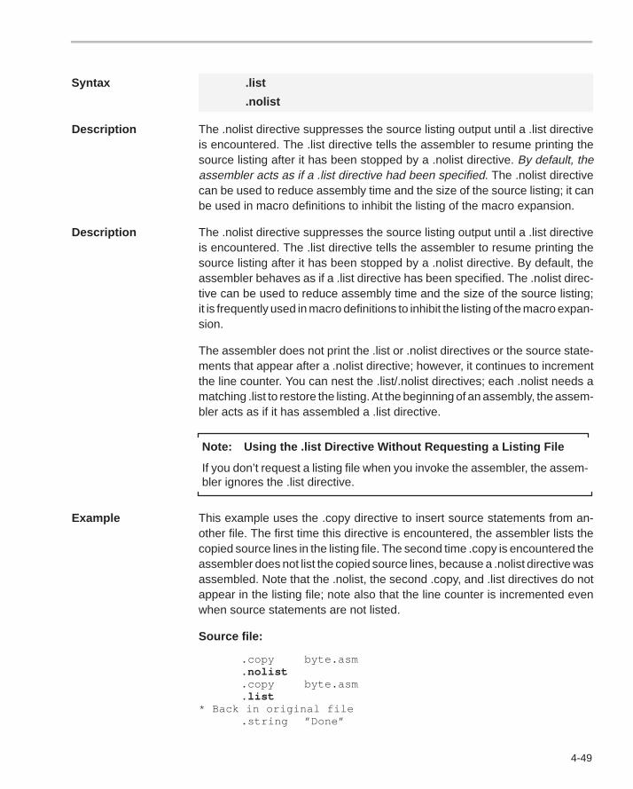
4-49
Syntax .list
.nolist
Description The .nolist directive suppresses the source listing output until a .list directiveis encountered. The .list directive tells the assembler to resume printing thesource listing after it has been stopped by a .nolist directive. By default, theassembler acts as if a .list directive had been specified. The .nolist directivecan be used to reduce assembly time and the size of the source listing; it canbe used in macro definitions to inhibit the listing of the macro expansion.
Description The .nolist directive suppresses the source listing output until a .list directiveis encountered. The .list directive tells the assembler to resume printing thesource listing after it has been stopped by a .nolist directive. By default, theassembler behaves as if a .list directive has been specified. The .nolist direc-tive can be used to reduce assembly time and the size of the source listing;it is frequently used in macro definitions to inhibit the listing of the macro expan-sion.
The assembler does not print the .list or .nolist directives or the source state-ments that appear after a .nolist directive; however, it continues to incrementthe line counter. You can nest the .list/.nolist directives; each .nolist needs amatching .list to restore the listing. At the beginning of an assembly, the assem-bler acts as if it has assembled a .list directive.
Note: Using the .list Directive Without Requesting a Listing File
If you don’t request a listing file when you invoke the assembler, the assem-bler ignores the .list directive.
Example This example uses the .copy directive to insert source statements from an-other file. The first time this directive is encountered, the assembler lists thecopied source lines in the listing file. The second time .copy is encountered theassembler does not list the copied source lines, because a .nolist directive wasassembled. Note that the .nolist, the second .copy, and .list directives do notappear in the listing file; note also that the line counter is incremented evenwhen source statements are not listed.
Source file:
.copy byte.asm
.nolist
.copy byte.asm
.list* Back in original file
.string ”Done”
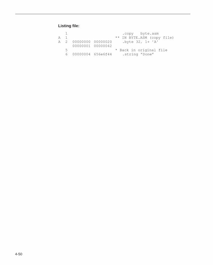
4-50
Listing file:
1 .copy byte.asmA 1 ** IN BYTE.ASM (copy file)A 2 00000000 00000020 .byte 32, 1+ ’A’
00000001 000000425 * Back in original file6 00000004 656e6f44 .string ”Done”
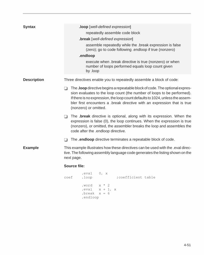
4-51
Syntax .loop [well-defined expression]
repeatedly assemble code block
.break [well-defined expression]
assemble repeatedly while the .break expression is false(zero); go to code following .endloop if true (nonzero)
.endloop
execute when .break directive is true (nonzero) or whennumber of loops performed equals loop count givenby .loop
Description Three directives enable you to repeatedly assemble a block of code:
� The .loop directive begins a repeatable block of code. The optional expres-sion evaluates to the loop count (the number of loops to be performed).If there is no expression, the loop count defaults to 1024, unless the assem-bler first encounters a .break directive with an expression that is true(nonzero) or omitted.
� The .break directive is optional, along with its expression. When theexpression is false (0), the loop continues. When the expression is true(nonzero), or omitted, the assembler breaks the loop and assembles thecode after the .endloop directive.
� The .endloop directive terminates a repeatable block of code.
Example This example illustrates how these directives can be used with the .eval direc-tive. The following assembly language code generates the listing shown on thenext page.
Source file:
.eval 0, xcoef .loop ;coefficient table
.word x * 2 .eval x + 1, x .break x = 6 .endloop
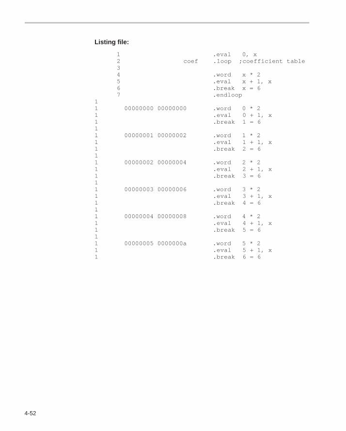
4-52
Listing file:
1 .eval 0, x 2 coef .loop ;coefficient table 3 4 .word x * 2 5 .eval x + 1, x 6 .break x = 6 7 .endloop1 1 00000000 00000000 .word 0 * 21 .eval 0 + 1, x1 .break 1 = 61 1 00000001 00000002 .word 1 * 21 .eval 1 + 1, x1 .break 2 = 61 1 00000002 00000004 .word 2 * 21 .eval 2 + 1, x1 .break 3 = 61 1 00000003 00000006 .word 3 * 21 .eval 3 + 1, x1 .break 4 = 61 1 00000004 00000008 .word 4 * 21 .eval 4 + 1, x1 .break 5 = 61 1 00000005 0000000a .word 5 * 21 .eval 5 + 1, x1 .break 6 = 6
4-53
Syntax .mlib [ ” ]filename[ ” ]
Description The .mlib directive provides the assembler with the name of a macro library.A macro library is a collection of files that contain macro definitions. These filesare bound into a single file (called an archive or library) by the archiver. Eachfile in a macro library may contain one macro definition that corresponds to thename of the file. Note that:
� Macro library members must be source files (not object files).
� The filename of a macro library member must be the same as the macroname, and its extension must be .asm.
The filename must follow host operating system conventions; it may be en-closed in double quotes. You can specify a full pathname (for example, .mlibC:\dsp\macs.lib). If you do not specify a full pathname, the assemblersearches for the file in:
1) The directory that contains the current source file.2) Any directories named with the -i assembler option.3) Any directories specified by the environment variable A_DIR.
For more information about the -i option and the environment variable, seeSection 3.5, Naming Alternate Directories for Assembler Input, on page 3-7.
When the assembler encounters an .mlib directive, it opens the library and cre-ates a table of its contents. The assembler enters the names of the individuallibrary members into the opcode table as library entries; this redefines any ex-isting opcodes or macros that have the same name. If one of these macros iscalled, the assembler extracts the entry from the library and loads it into themacro table. The assembler expands the library entry in the same manner asother macros, but it does not place the source code into the listing. Only mac-ros that are actually called from the library are extracted.
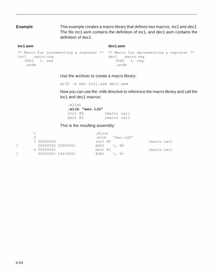
4-54
Example This example creates a macro library that defines two macros, inc1 and dec1.The file inc1.asm contains the definition of inc1, and dec1.asm contains thedefinition of dec1.
inc1.asm dec1.asm
** Macro for incrementing a register **inc1 .macro reg
ADDI 1, reg.endm
** Macro for decrementing a register **dec1 .macro reg
SUBI 1, reg.endm
Use the archiver to create a macro library:
ar30 –a mac inc1.asm dec1.asm
Now you can use the .mlib directive to reference the macro library and call theinc1 and dec1 macros:
.mlist
.mlib ”mac.lib”inc1 R0 ;macro calldec1 R1 ;macro call
This is the resulting assembly:
1 .mlist 2 .mlib ”mac.lib” 3 00000000 inc1 R0 ;macro call1 00000000 02600001 ADDI 1, R0 4 00000001 dec1 R1 ;macro call1 00000001 18610001 SUBI 1, R1
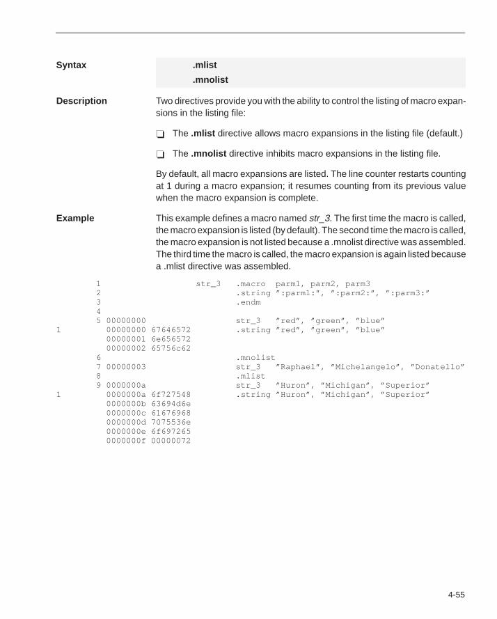
4-55
Syntax .mlist
.mnolist
Description Two directives provide you with the ability to control the listing of macro expan-sions in the listing file:
� The .mlist directive allows macro expansions in the listing file (default.)
� The .mnolist directive inhibits macro expansions in the listing file.
By default, all macro expansions are listed. The line counter restarts countingat 1 during a macro expansion; it resumes counting from its previous valuewhen the macro expansion is complete.
Example This example defines a macro named str_3. The first time the macro is called,the macro expansion is listed (by default). The second time the macro is called,the macro expansion is not listed because a .mnolist directive was assembled.The third time the macro is called, the macro expansion is again listed becausea .mlist directive was assembled.
1 str_3 .macro parm1, parm2, parm32 .string ”:parm1:”, ”:parm2:”, ”:parm3:”3 .endm45 00000000 str_3 ”red”, ”green”, ”blue”
1 00000000 67646572 .string ”red”, ”green”, ”blue”00000001 6e65657200000002 65756c62
6 .mnolist7 00000003 str_3 ”Raphael”, ”Michelangelo”, ”Donatello”8 .mlist9 0000000a str_3 ”Huron”, ”Michigan”, ”Superior”
1 0000000a 6f727548 .string ”Huron”, ”Michigan”, ”Superior”0000000b 63694d6e0000000c 616769680000000d 7075536e0000000e 6f6972650000000f 00000072
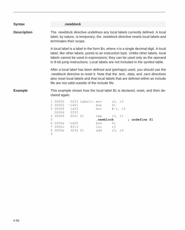
4-56
Syntax .newblock
Description The .newblock directive undefines any local labels currently defined. A locallabel, by nature, is temporary; the .newblock directive resets local labels andterminates their scope.
A local label is a label in the form $n, where n is a single decimal digit. A locallabel, like other labels, points to an instruction byte. Unlike other labels, locallabels cannot be used in expressions; they can be used only as the operandin 8-bit jump instructions. Local labels are not included in the symbol table.
After a local label has been defined and (perhaps) used, you should use the.newblock directive to reset it. Note that the .text, .data, and .sect directivesalso reset local labels and that local labels that are defined within an includefile are not valid outside of the include file.
Example This example shows how the local label $1 is declared, reset, and then de-clared again.
1 00000 0223 Label1: mov r2, r32 00002 ’c401 bne $13 00004 1a03 mov #–1, r3 00006 ffff 4 00008 6031 $1 cmp r3, r15 .newblock ; undefine $16 0000a ’c400 bne $17 0000c 8213 inc r38 0000e 3034 $1 add r3, r49
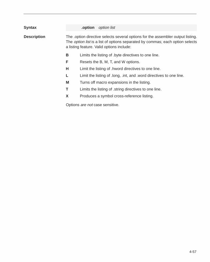
4-57
Syntax .option option list
Description The .option directive selects several options for the assembler output listing.The option list is a list of options separated by commas; each option selectsa listing feature. Valid options include:
B Limits the listing of .byte directives to one line.
F Resets the B, M, T, and W options.
H Limit the listing of .hword directives to one line.
L Limit the listing of .long, .int, and .word directives to one line.
M Turns off macro expansions in the listing.
T Limits the listing of .string directives to one line.
X Produces a symbol cross-reference listing.
Options are not case sensitive.
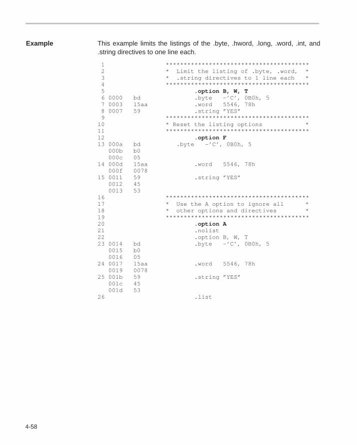
4-58
Example This example limits the listings of the .byte, .hword, .long, .word, .int, and.string directives to one line each.
1 ****************************************2 * Limit the listing of .byte, .word, *3 * .string directives to 1 line each *4 ****************************************5 .option B, W, T6 0000 bd .byte –’C’, 0B0h, 57 0003 15aa .word 5546, 78h8 0007 59 .string ”YES”9 ****************************************
10 * Reset the listing options *11 ****************************************12 .option F13 000a bd .byte –’C’, 0B0h, 5
000b b0000c 05
14 000d 15aa .word 5546, 78h000f 0078
15 0011 59 .string ”YES”0012 450013 53
16 ****************************************17 * Use the A option to ignore all *18 * other options and directives *19 ****************************************20 .option A21 .nolist22 .option B, W, T23 0014 bd .byte –’C’, 0B0h, 5
0015 b00016 05
24 0017 15aa .word 5546, 78h0019 0078
25 001b 59 .string ”YES”001c 45001d 53
26 .list
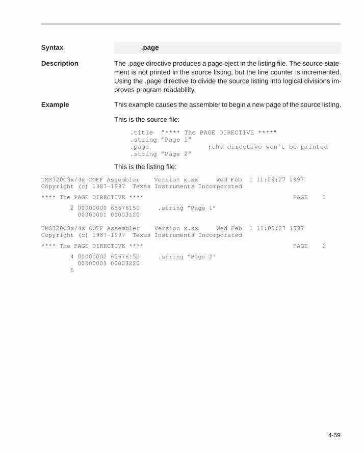
4-59
Syntax .page
Description The .page directive produces a page eject in the listing file. The source state-ment is not printed in the source listing, but the line counter is incremented.Using the .page directive to divide the source listing into logical divisions im-proves program readability.
Example This example causes the assembler to begin a new page of the source listing.
This is the source file:
.title ”**** The PAGE DIRECTIVE ****” .string ”Page 1” .page ;the directive won’t be printed .string ”Page 2”
This is the listing file:
TMS320C3x/4x COFF Assembler Version x.xx Wed Feb 1 11:09:27 1997Copyright (c) 1987–1997 Texas Instruments Incorporated
**** The PAGE DIRECTIVE **** PAGE 1
2 00000000 65676150 .string ”Page 1” 00000001 00003120
TMS320C3x/4x COFF Assembler Version x.xx Wed Feb 1 11:09:27 1997Copyright (c) 1987–1997 Texas Instruments Incorporated
**** The PAGE DIRECTIVE **** PAGE 2
4 00000002 65676150 .string ”Page 2” 00000003 00003220 5
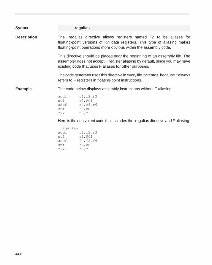
4-60
Syntax .regalias
Description The .regalias directive allows registers named Fn to be aliases forfloating-point versions of Rn data registers. This type of aliasing makesfloating-point operations more obvious within the assembly code.
This directive should be placed near the beginning of an assembly file. Theassembler does not accept F register aliasing by default, since you may haveexisting code that uses F aliases for other purposes.
The code generator uses this directive in every file it creates, because it alwaysrefers to F registers in floating-point instructions.
Example The code below displays assembly instructions without F aliasing:
addi r1,r2,r3sti r3,@C1addf r4,r5,r6stf r6,@C2fix r3,r3
Here is the equivalent code that includes the .regalias directive and F aliasing:
.regaliasaddi r1,r2,r3sti r3,@C1addf f4,f5,f6stf f6,@C2fix f3,r3
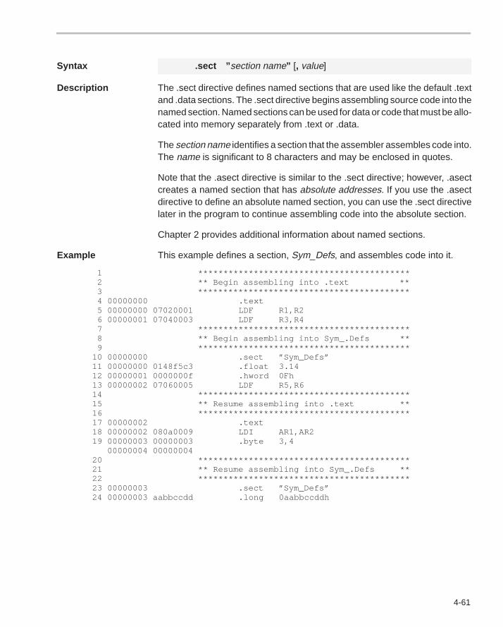
4-61
Syntax .sect ” section name” [, value]
Description The .sect directive defines named sections that are used like the default .textand .data sections. The .sect directive begins assembling source code into thenamed section. Named sections can be used for data or code that must be allo-cated into memory separately from .text or .data.
The section name identifies a section that the assembler assembles code into.The name is significant to 8 characters and may be enclosed in quotes.
Note that the .asect directive is similar to the .sect directive; however, .asectcreates a named section that has absolute addresses. If you use the .asectdirective to define an absolute named section, you can use the .sect directivelater in the program to continue assembling code into the absolute section.
Chapter 2 provides additional information about named sections.
Example This example defines a section, Sym_Defs, and assembles code into it.
1 ****************************************** 2 ** Begin assembling into .text ** 3 ****************************************** 4 00000000 .text 5 00000000 07020001 LDF R1,R2 6 00000001 07040003 LDF R3,R4 7 ****************************************** 8 ** Begin assembling into Sym_.Defs ** 9 ****************************************** 10 00000000 .sect ”Sym_Defs” 11 00000000 0148f5c3 .float 3.14 12 00000001 0000000f .hword 0Fh 13 00000002 07060005 LDF R5,R6 14 ****************************************** 15 ** Resume assembling into .text ** 16 ****************************************** 17 00000002 .text 18 00000002 080a0009 LDI AR1,AR2 19 00000003 00000003 .byte 3,4 00000004 00000004 20 ****************************************** 21 ** Resume assembling into Sym_.Defs ** 22 ****************************************** 23 00000003 .sect ”Sym_Defs” 24 00000003 aabbccdd .long 0aabbccddh
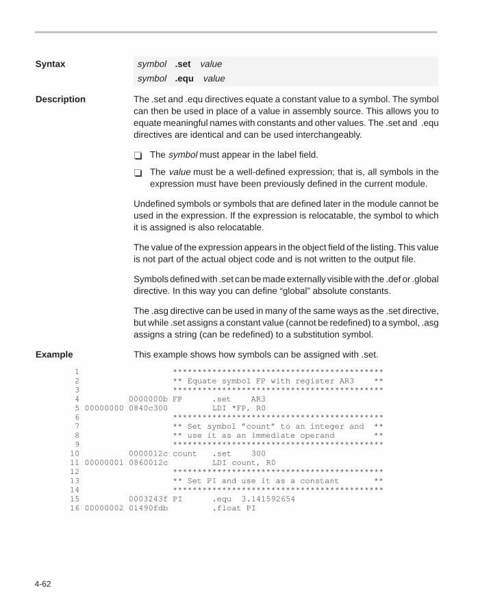
4-62
Syntax symbol .set value
symbol .equ value
Description The .set and .equ directives equate a constant value to a symbol. The symbolcan then be used in place of a value in assembly source. This allows you toequate meaningful names with constants and other values. The .set and .equdirectives are identical and can be used interchangeably.
� The symbol must appear in the label field.
� The value must be a well-defined expression; that is, all symbols in theexpression must have been previously defined in the current module.
Undefined symbols or symbols that are defined later in the module cannot beused in the expression. If the expression is relocatable, the symbol to whichit is assigned is also relocatable.
The value of the expression appears in the object field of the listing. This valueis not part of the actual object code and is not written to the output file.
Symbols defined with .set can be made externally visible with the .def or .globaldirective. In this way you can define “global” absolute constants.
The .asg directive can be used in many of the same ways as the .set directive,but while .set assigns a constant value (cannot be redefined) to a symbol, .asgassigns a string (can be redefined) to a substitution symbol.
Example This example shows how symbols can be assigned with .set.
1 ******************************************* 2 ** Equate symbol FP with register AR3 ** 3 ******************************************* 4 0000000b FP .set AR3 5 00000000 0840c300 LDI *FP, R0 6 ******************************************* 7 ** Set symbol ”count” to an integer and ** 8 ** use it as an immediate operand ** 9 ******************************************* 10 0000012c count .set 300 11 00000001 0860012c LDI count, R0 12 ******************************************* 13 ** Set PI and use it as a constant ** 14 ******************************************* 15 0003243f PI .equ 3.141592654 16 00000002 01490fdb .float PI
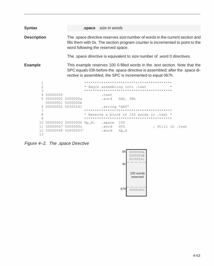
4-63
Syntax .space size in words
Description The .space directive reserves size number of words in the current section andfills them with 0s. The section program counter is incremented to point to theword following the reserved space.
The .space directive is equivalent to size number of .word 0 directives.
Example This example reserves 100 0-filled words in the .text section. Note that theSPC equals 03h before the .space directive is assembled; after the .space di-rective is assembled, the SPC is incremented to equal 067h.
1 ***************************************** 2 * Begin assembling into .text * 3 ***************************************** 4 00000000 .text 5 00000000 0000000a .word 0Ah, 0Bh 00000001 0000000b 6 00000002 00305241 .string ”AR0” 7 ***************************************** 8 * Reserve a block of 100 words in .text * 9 ***************************************** 10 00000003 00000000 Sp_X: .space 100 11 00000067 0000000c .word 0Ch ; Still in .text 12 00000068 00000003’ .word Sp_X 13
Figure 4–2. The .space Directive
0h 0000000A0000000B00305241
3h
0000000C67h
100 wordsreserved
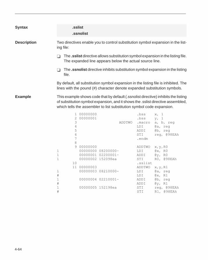
4-64
Syntax .sslist
.ssnolist
Description Two directives enable you to control substitution symbol expansion in the list-ing file:
� The .sslist directive allows substitution symbol expansion in the listing file.The expanded line appears below the actual source line.
� The .ssnolist directive inhibits substitution symbol expansion in the listingfile.
By default, all substitution symbol expansion in the listing file is inhibited. Thelines with the pound (#) character denote expanded substitution symbols.
Example This example shows code that by default (.ssnolist directive) inhibits the listingof substitution symbol expansion, and it shows the .sslist directive assembled,which tells the assembler to list substitution symbol code expansion.
1 00000000 .bss x, 1 2 00000001 .bss y, 1 3 ADDTWO .macro a, b, reg 4 LDI @a, reg 5 ADDI @b, reg 6 STI reg, @98EAh 7 .endm 8 9 00000000 ADDTWO x,y,R0 1 00000000 08200000– LDI @x, R01 00000001 02200001– ADDI @y, R01 00000002 152098ea STI R0, @98EAh 10 .sslist 11 00000003 ADDTWO x,y,R11 00000003 08210000– LDI @a, reg# LDI @x, R11 00000004 02210001– ADDI @b, reg# ADDI @y, R11 00000005 152198ea STI reg, @98EAh# STI R1, @98EAh
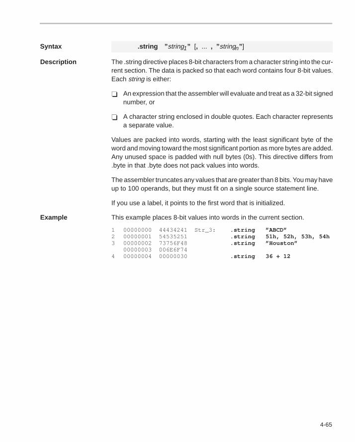
4-65
Syntax .string ” string1 ” [, ... , ” stringn ” ]
Description The .string directive places 8-bit characters from a character string into the cur-rent section. The data is packed so that each word contains four 8-bit values.Each string is either:
� An expression that the assembler will evaluate and treat as a 32-bit signednumber, or
� A character string enclosed in double quotes. Each character representsa separate value.
Values are packed into words, starting with the least significant byte of theword and moving toward the most significant portion as more bytes are added.Any unused space is padded with null bytes (0s). This directive differs from.byte in that .byte does not pack values into words.
The assembler truncates any values that are greater than 8 bits. You may haveup to 100 operands, but they must fit on a single source statement line.
If you use a label, it points to the first word that is initialized.
Example This example places 8-bit values into words in the current section.
1 00000000 44434241 Str_3: .string ”ABCD”2 00000001 54535251 .string 51h, 52h, 53h, 54h3 00000002 73756F48 .string ”Houston”
00000003 006E6F744 00000004 00000030 .string 36 + 12
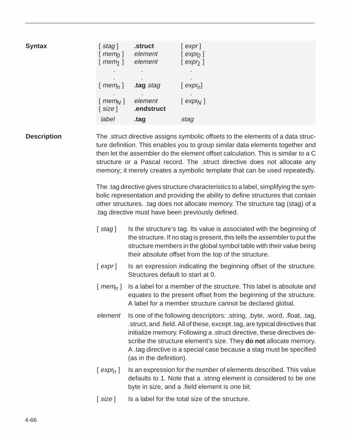
4-66
Syntax [ stag ] .struct [ expr ][ mem0 ] element [ expr0 ][ mem1 ] element [ expr1 ] . . . . . .[ memn ] .tag stag [ exprn] . . .[ memN ] element [ exprN ][ size ] .endstruct
label .tag stag
Description The .struct directive assigns symbolic offsets to the elements of a data struc-ture definition. This enables you to group similar data elements together andthen let the assembler do the element offset calculation. This is similar to a Cstructure or a Pascal record. The .struct directive does not allocate anymemory; it merely creates a symbolic template that can be used repeatedly.
The .tag directive gives structure characteristics to a label, simplifying the sym-bolic representation and providing the ability to define structures that containother structures. .tag does not allocate memory. The structure tag (stag) of a.tag directive must have been previously defined.
[ stag ] Is the structure’s tag. Its value is associated with the beginning ofthe structure. If no stag is present, this tells the assembler to put thestructure members in the global symbol table with their value beingtheir absolute offset from the top of the structure.
[ expr ] Is an expression indicating the beginning offset of the structure.Structures default to start at 0.
[ memn ] Is a label for a member of the structure. This label is absolute andequates to the present offset from the beginning of the structure.A label for a member structure cannot be declared global.
element Is one of the following descriptors: .string, .byte, .word, .float, .tag,.struct, and .field. All of these, except .tag, are typical directives thatinitialize memory. Following a .struct directive, these directives de-scribe the structure element’s size. They do not allocate memory.A .tag directive is a special case because a stag must be specified(as in the definition).
[ exprn ] Is an expression for the number of elements described. This valuedefaults to 1. Note that a .string element is considered to be onebyte in size, and a .field element is one bit.
[ size ] Is a label for the total size of the structure.
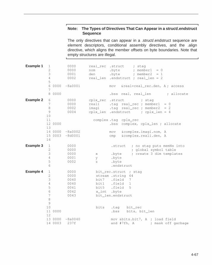
4-67
Note: The Types of Directives That Can Appear in a struct/.endstruct Sequence
The only directives that can appear in a .struct/.endstruct sequence areelement descriptors, conditional assembly directives, and the .aligndirective, which aligns the member offsets on byte boundaries. Note thatempty structures are illegal.
Example 1 1 0000 real_rec .struct ; stag2 0000 nom .byte ; member1 = 03 0001 den .byte ; member2 = 14 0002 real_len .endstruct ; real_len = 256 0000 –8a0001 mov &real+real_rec.den, A ; access78 0000 .bss real, real_len ; allocate
Example 2 6 0000 cplx_rec .struct ; stag7 0000 reali .tag real_rec ; member1 = 08 0002 imagi .tag real_rec ; member2 = 29 0004 cplx_len .endstruct ; cplx_len = 4
1011 complex .tag cplx_rec12 0000 .bss complex, cplx_len ; allocate1314 0000 –8a0002 mov &complex.imagi.nom, A15 0003 –8d0001 cmp &complex.reali.den, A16
Example 3 1 0000 .struct ; no stag puts memNs into2 0000 ; global symbol table3 0000 x .byte ; create 3 dim templates4 0001 y .byte5 0002 z .byte6 .endstruct
Example 4 1 0000 bit_rec.struct ; stag2 0000 stream .string 643 0040 bit7 .field 74 0040 bit1 .field 15 0041 bit5 .field 56 0042 x_int .byte7 0043 bit_len.endstruct89
10 bits .tag bit_rec11 0000 .bss bits, bit_len1213 0000 –8a0040 mov &bits.bit7, A ; load field14 0003 237f and #7fh, A ; mask off garbage
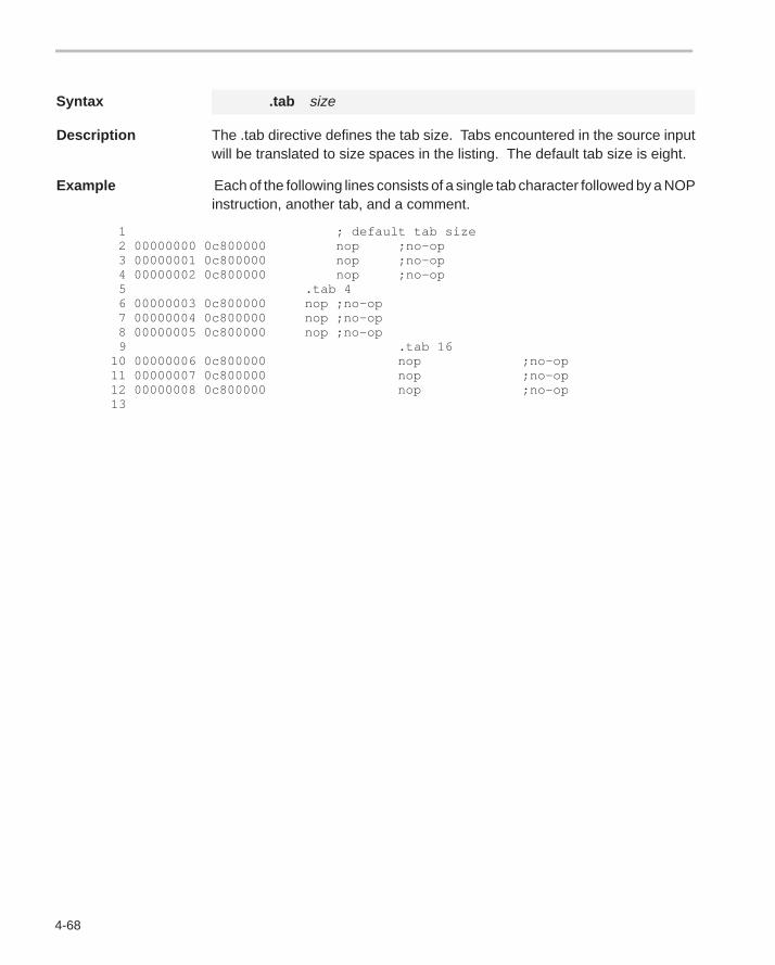
4-68
Syntax .tab size
Description The .tab directive defines the tab size. Tabs encountered in the source inputwill be translated to size spaces in the listing. The default tab size is eight.
Example Each of the following lines consists of a single tab character followed by a NOPinstruction, another tab, and a comment.
1 ; default tab size 2 00000000 0c800000 nop ;no–op 3 00000001 0c800000 nop ;no–op 4 00000002 0c800000 nop ;no–op 5 .tab 4 6 00000003 0c800000 nop ;no–op 7 00000004 0c800000 nop ;no–op 8 00000005 0c800000 nop ;no–op 9 .tab 16 10 00000006 0c800000 nop ;no–op 11 00000007 0c800000 nop ;no–op 12 00000008 0c800000 nop ;no–op 13
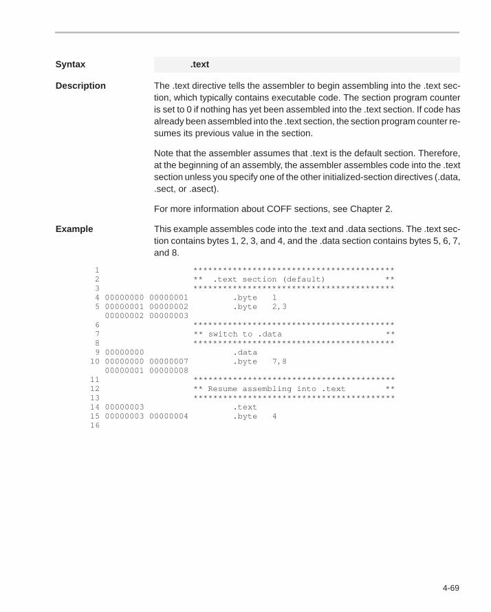
4-69
Syntax .text
Description The .text directive tells the assembler to begin assembling into the .text sec-tion, which typically contains executable code. The section program counteris set to 0 if nothing has yet been assembled into the .text section. If code hasalready been assembled into the .text section, the section program counter re-sumes its previous value in the section.
Note that the assembler assumes that .text is the default section. Therefore,at the beginning of an assembly, the assembler assembles code into the .textsection unless you specify one of the other initialized-section directives (.data,.sect, or .asect).
For more information about COFF sections, see Chapter 2.
Example This example assembles code into the .text and .data sections. The .text sec-tion contains bytes 1, 2, 3, and 4, and the .data section contains bytes 5, 6, 7,and 8.
1 ***************************************** 2 ** .text section (default) ** 3 ***************************************** 4 00000000 00000001 .byte 1 5 00000001 00000002 .byte 2,3 00000002 00000003 6 ***************************************** 7 ** switch to .data ** 8 ***************************************** 9 00000000 .data 10 00000000 00000007 .byte 7,8 00000001 00000008 11 ***************************************** 12 ** Resume assembling into .text ** 13 ***************************************** 14 00000003 .text 15 00000003 00000004 .byte 4 16
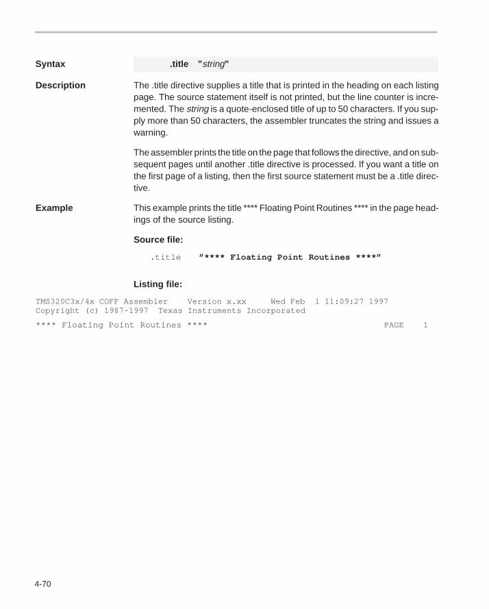
4-70
Syntax .title ” string”
Description The .title directive supplies a title that is printed in the heading on each listingpage. The source statement itself is not printed, but the line counter is incre-mented. The string is a quote-enclosed title of up to 50 characters. If you sup-ply more than 50 characters, the assembler truncates the string and issues awarning.
The assembler prints the title on the page that follows the directive, and on sub-sequent pages until another .title directive is processed. If you want a title onthe first page of a listing, then the first source statement must be a .title direc-tive.
Example This example prints the title **** Floating Point Routines **** in the page head-ings of the source listing.
Source file:
.title ”**** Floating Point Routines ****”
Listing file:
TMS320C3x/4x COFF Assembler Version x.xx Wed Feb 1 11:09:27 1997Copyright (c) 1987–1997 Texas Instruments Incorporated
**** Floating Point Routines **** PAGE 1
4-71
Syntax symbol .usect ” section name”, size in words [, word alignment flag]
Description The .usect directive reserves space for variables in an uninitialized, namedsection. This directive is similar to the .bss directive; both simply reserve spacefor data and have no contents. However, .usect defines additional sectionsthat can be placed anywhere in memory, independently of the .bss section.
� The symbol points to the first location reserved by this invocation of the.usect directive. The symbol corresponds to the name of the variable thatyou’re reserving space for.
� Only the first 8 characters of the section name are significant. The sectionname may be enclosed in quotes. This parameter names the uninitializedsection.
� The size is an expression that defines the number of words that will be re-served in section name.
Other sections directives (.text, .data, .sect, and .asect) end the current sec-tion and tell the assembler to begin assembling into another section. The.usect and the .bss directives, however, do not affect the current section. Theassembler assembles the .usect and the .bss directives and then resumes as-sembling into the current section.
You can repeat the .usect directive to define more than one variable in thespecified section. Variables that can be located contiguously in memory canbe defined in the same section by using multiple .usect directives with thesame section name.
For more information about COFF sections, see Chapter 2.
Example This example uses the .usect directive to define two uninitialized, named sec-tions, var1 and var2. The symbol ptr points to the first word reserved in the var1section. The symbol array points to the first word in a block of 100 words re-served in var1, and dflag points to the first word in a block of 50 words in var1.The symbol vec points to the first word reserved in the var2 section.
Figure 4–3 on page 4-72 shows how this example reserves space in twouninitialized sections, var1 and var2.
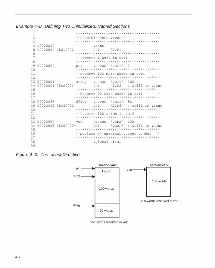
4-72
Example 4–8. Defining Two Uninitialized, Named Sections
1 *************************************** 2 * Assemble into .text * 3 *************************************** 4 00000000 .text 5 00000000 08010000 LDI R0,R1 6 *************************************** 7 * Reserve 1 word in var1 * 8 *************************************** 9 00000000 ptr .usect ”var1”, 1 10 *************************************** 11 * Reserve 100 more words in var1 * 12 *************************************** 13 00000001 array .usect ”var1”, 100 14 00000001 08020001 LDI R1,R2 ; Still in .text 15 *************************************** 16 * Reserve 50 more words in var1 * 17 *************************************** 18 00000065 dflag .usect ”var1”, 50 19 00000002 08030002 LDI R2,R3 ; Still in .text 20 *************************************** 21 * Reserve 100 words in var2 * 22 *************************************** 23 00000000 vec .usect ”var2”, 100 24 00000003 08200000– LDI @vec,R0 ; Still in .text 25 *************************************** 26 * Declare an external .usect symbol * 27 *************************************** 28 .global array 29
Figure 4–3. The .usect Directive
1 word
100 words
50 words
100 words
section var1 section var2
151 words reserved in var1
100 words reserved in var2
ptr
array
dflag
vec

4-73
Syntax .version generation number
Description The .version directive tells the assembler which generation processor thiscode is for. Valid generation numbers are 30, 31, 32, 40 and 44. The defaultis 30.The version directive must appear before an instruction or directive, orelse an error will occur. The version directive can be used instead of the –vcommand line option.
Example In this example, the code will always be assembled and linked for the ’C40 pro-cessor unless overridden by a –v command line option:
.version 40 ; target is TMS320C40ADDI 5, *+AR0(5), R0
5-1Instruction Set
Instruction Set
The TMS320C3x/C4x assembler supports a base set of general-purposeinstructions as well as arithmetic instructions that are particularly suited fordigital signal processing and other numeric-intensive applications.
This chapter does not cover topics such as opcodes or instruction timing; theTMS320C3x User’s Guide and TMS320C4x User’s Guide discuss theinstruction set in detail. Those user’s guides also contain an alphabetical pre-sentation, which is similar to the directives reference in Chapter 4 of this book.
This chapter provides a general summary of the TMS320C3x andTMS320C4x instruction sets:
� Section 5.1 lists information that will help you use the instruction set,including addressing modes, optional syntaxes, condition codes andflags, and abbreviations and symbols.
� Section 5.2 describes the instructions according to function.
� Section 5.3 contains the instruction set summary table, which provideseach instruction’s syntax, operation, and description.
Topic Page
5.1 Using the Instruction Set Summary 5-2. . . . . . . . . . . . . . . . . . . . . . . . . . . . .
5.2 Functional Summary of the Instruction Set 5-8. . . . . . . . . . . . . . . . . . . . . .
5.3 Instruction Set Summary Table 5-20. . . . . . . . . . . . . . . . . . . . . . . . . . . . . . . .
Chapter 5
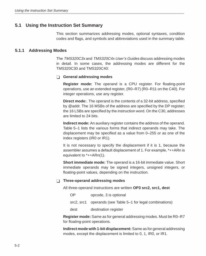
Using the Instruction Set Summary
5-2
5.1 Using the Instruction Set Summary
This section summarizes addressing modes, optional syntaxes, conditioncodes and flags, and symbols and abbreviations used in the summary table.
5.1.1 Addressing Modes
The TMS320C3x and TMS320C4x User’s Guides discuss addressing modesin detail. In some cases, the addressing modes are different for theTMS320C30 and TMS320C40:
� General addressing modes
Register mode: The operand is a CPU register. For floating-pointoperations, use an extended register, (R0–R7) (R0–R11 on the C40). Forinteger operations, use any register.
Direct mode: . The operand is the contents of a 32-bit address, specifiedby @addr. The 16 MSBs of the address are specified by the DP register;the 16 LSBs are specified by the instruction word. On the C30, addressesare limited to 24 bits.
Indirect mode: An auxiliary register contains the address of the operand.Table 5–1 lists the various forms that indirect operands may take. Thedisplacement may be specified as a value from 0–255 or as one of theindex registers (IR0 or IR1).
It is not necessary to specify the displacement if it is 1, because theassembler assumes a default displacement of 1. For example, *++ARn isequivalent to *++ARn(1).
Short immediate mode: The operand is a 16-bit immediate value. Shortimmediate operands may be signed integers, unsigned integers, orfloating-point values, depending on the instruction.
� Three-operand addressing modes
All three-operand instructions are written OP3 src2, src1, dest
OP opcode, 3 is optional
src2, src1 operands (see Table 5–1 for legal combinations)
dest destination register
Register mode: Same as for general addressing modes. Must be R0–R7for floating-point operations.
Indirect mode with 1-bit displacement: Same as for general addressingmodes, except the displacement is limited to 0, 1, IR0, or IR1.
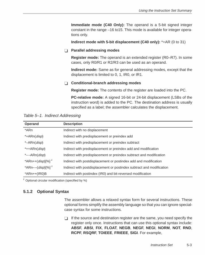
Using the Instruction Set Summary
5-3Instruction Set
Immediate mode (C40 Only): The operand is a 5-bit signed integerconstant in the range –16 to15. This mode is available for integer opera-tions only.
Indirect mode with 5-bit displacement (C40 only): *+AR (0 to 31)
� Parallel addressing modes
Register mode: The operand is an extended register (R0–R7). In somecases, only R0/R1 or R2/R3 can be used as an operand.
Indirect mode: Same as for general addressing modes, except that thedisplacement is limited to 0, 1, IR0, or IR1.
� Conditional-branch addressing modes
Register mode: The contents of the register are loaded into the PC.
PC-relative mode: A signed 16-bit or 24-bit displacement (LSBs of theinstruction word) is added to the PC. The destination address is usuallyspecified as a label; the assembler calculates the displacement.
Table 5–1. Indirect Addressing
Operand Description
*ARn Indirect with no displacement
*+ARn(disp) Indirect with predisplacement or preindex add
*–ARn(disp) Indirect with predisplacement or preindex subtract
*++ARn(disp) Indirect with predisplacement or preindex add and modification
*––ARn(disp) Indirect with predisplacement or preindex subtract and modification
*ARn++(disp)[%] † Indirect with postdisplacement or postindex add and modification
*ARn––(disp)[%] † Indirect with postdisplacement or postindex subtract and modification
*ARn++(IR0)B Indirect with postindex (IR0) and bit-reversed modification
† Optional circular modification (specified by %)
5.1.2 Optional Syntax
The assembler allows a relaxed syntax form for several instructions. Theseoptional forms simplify the assembly language so that you can ignore special-case syntax for some instructions.
� If the source and destination register are the same, you need specify theregister only once. Instructions that can use this optional syntax include:ABSF, ABSI , FIX, FLOAT, NEGB, NEGF, NEGI, NORM, NOT, RND,RCPF, RSQRF, TOIEEE, FRIEEE, SIGI. For example,
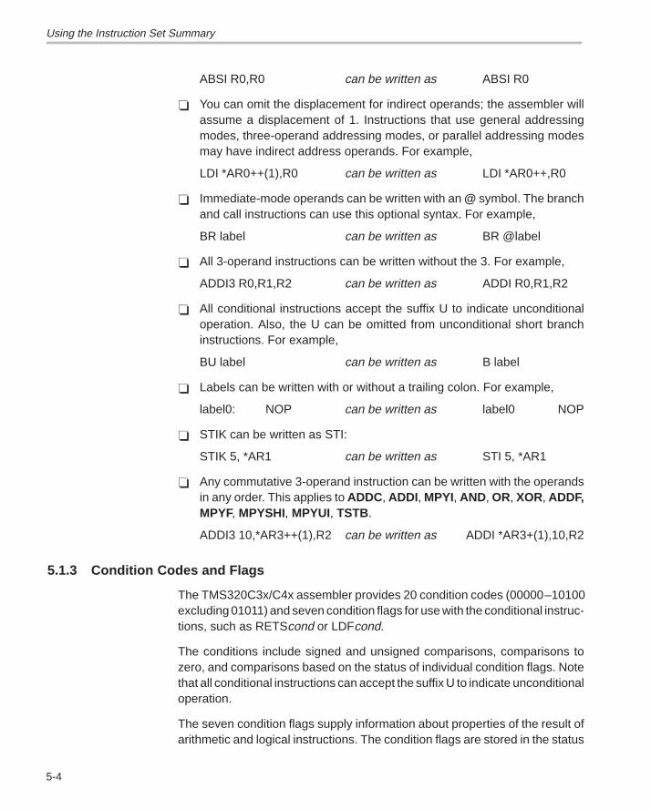
Using the Instruction Set Summary
5-4
ABSI R0,R0 can be written as ABSI R0
� You can omit the displacement for indirect operands; the assembler willassume a displacement of 1. Instructions that use general addressingmodes, three-operand addressing modes, or parallel addressing modesmay have indirect address operands. For example,
LDI *AR0++(1),R0 can be written as LDI *AR0++,R0
� Immediate-mode operands can be written with an @ symbol. The branchand call instructions can use this optional syntax. For example,
BR label can be written as BR @label
� All 3-operand instructions can be written without the 3. For example,
ADDI3 R0,R1,R2 can be written as ADDI R0,R1,R2
� All conditional instructions accept the suffix U to indicate unconditionaloperation. Also, the U can be omitted from unconditional short branchinstructions. For example,
BU label can be written as B label
� Labels can be written with or without a trailing colon. For example,
label0: NOP can be written as label0 NOP
� STIK can be written as STI:
STIK 5, *AR1 can be written as STI 5, *AR1
� Any commutative 3-operand instruction can be written with the operandsin any order. This applies to ADDC, ADDI, MPYI, AND, OR, XOR, ADDF,MPYF, MPYSHI, MPYUI, TSTB.
ADDI3 10,*AR3++(1),R2 can be written as ADDI *AR3+(1),10,R2
5.1.3 Condition Codes and Flags
The TMS320C3x/C4x assembler provides 20 condition codes (00000–10100excluding 01011) and seven condition flags for use with the conditional instruc-tions, such as RETScond or LDFcond.
The conditions include signed and unsigned comparisons, comparisons tozero, and comparisons based on the status of individual condition flags. Notethat all conditional instructions can accept the suffix U to indicate unconditionaloperation.
The seven condition flags supply information about properties of the result ofarithmetic and logical instructions. The condition flags are stored in the status
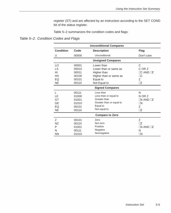
Using the Instruction Set Summary
5-5Instruction Set
register (ST) and are affected by an instruction according to the SET CONDbit of the status register.
Table 5–2 summarizes the condition codes and flags:
Table 5–2. Condition Codes and Flags
Unconditional Compares
Condition Code Description Flag
U 00000 Unconditional Don’t care
Unsigned Compares
LOLSHIHSEQNE
000010001000011001000010100110
Lower than Lower than or same asHigher thanHigher than or same asEqual toNot Equal to
CC OR Z∼C AND ∼Z∼CZ∼Z
Signed Compares
LLEGTGEEQNE
001110100001001010100010100110
Less thanLess than or equal toGreater thanGreater than or equal toEqual toNot equal to
NN OR Z∼N AND ∼Z∼NZ∼Z
Compare to Zero
ZNZPNNN
0010100110010010011101010
ZeroNot zeroPositiveNegativeNonnegative
Z∼Z∼N AND ∼ZN∼N
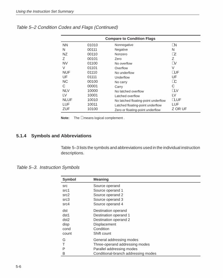
Using the Instruction Set Summary
5-6
Table 5–2 Condition Codes and Flags (Continued)
Compare to Condition Flags
NNNNZZNVVNUFUFNCCNLVLVNLUFLUFZUF
010100011100110001010110001101011100111100100000011000010001100101001110100
NonnegativeNegativeNonzeroZeroNo overflowOverflowNo underflowUnderflowNo carryCarryNo latched overflowLatched overflowNo latched floating-point underflowLatched floating-point underflowZero or floating-point underflow
∼NN ∼ZZ ∼VV ∼UFUF ∼CC ∼LVLV ∼LUFLUF Z OR UF
Note: The ∼ means logical complement .
5.1.4 Symbols and Abbreviations
Table 5–3 lists the symbols and abbreviations used in the individual instructiondescriptions.
Table 5–3. Instruction Symbols
Symbol Meaning
srcsrc1src2src3src4
Source operandSource operand 1Source operand 2Source operand 3Source operand 4
dstdst1dst2dispcondcount
Destination operandDestination operand 1Destination operand 2DisplacementConditionShift count
GTPB
General addressing modesThree-operand addressing modesParallel addressing modesConditional-branch addressing modes
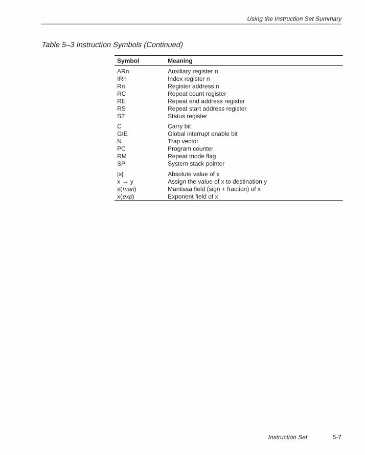
Using the Instruction Set Summary
5-7Instruction Set
Table 5–3 Instruction Symbols (Continued)
Symbol Meaning
ARnIRnRnRCRERSST
Auxiliary register nIndex register nRegister address nRepeat count registerRepeat end address registerRepeat start address registerStatus register
CGIENPCRMSP
Carry bitGlobal interrupt enable bitTrap vectorProgram counterRepeat mode flagSystem stack pointer
|x|x → yx(man)x(exp)
Absolute value of xAssign the value of x to destination yMantissa field (sign + fraction) of xExponent field of x
Functional Summary of the Instruction Set
5-8
5.2 Functional Summary of the Instruction Set
The TMS320C3x/C4x instruction set is exceptionally well-suited to digital sig-nal processing and other numeric-intensive applications. All instructions area single machine word long, and most instructions take a single cycle to ex-ecute.
The instruction set contains 135 instructions organized into the followingfunctional groups:
Subject PageLoad and Store 5-8. . . . . . . . . . . . . . . . . . . . . . . . . . . . . . . . . . . . . . . . . . . . . . . . . Arithmetic 5-10. . . . . . . . . . . . . . . . . . . . . . . . . . . . . . . . . . . . . . . . . . . . . . . . . . . . . Logic 5-11. . . . . . . . . . . . . . . . . . . . . . . . . . . . . . . . . . . . . . . . . . . . . . . . . . . . . . . . . Program Control 5-11. . . . . . . . . . . . . . . . . . . . . . . . . . . . . . . . . . . . . . . . . . . . . . . Interlocked Operations 5-12. . . . . . . . . . . . . . . . . . . . . . . . . . . . . . . . . . . . . . . . . Conversion 5-13. . . . . . . . . . . . . . . . . . . . . . . . . . . . . . . . . . . . . . . . . . . . . . . . . . . Three Operand 5-13. . . . . . . . . . . . . . . . . . . . . . . . . . . . . . . . . . . . . . . . . . . . . . . . Parallel 5-14. . . . . . . . . . . . . . . . . . . . . . . . . . . . . . . . . . . . . . . . . . . . . . . . . . . . . . . TMS320C40 only 5-18. . . . . . . . . . . . . . . . . . . . . . . . . . . . . . . . . . . . . . . . . . . . . . LDP and LDPK Instructions 5-19. . . . . . . . . . . . . . . . . . . . . . . . . . . . . . . . . . . . .
5.2.1 Load-and-Store Instructions
The TMS320C3x and TMS320C4x support 23 load and store instructions,which are summarized in Table 5–4. These instructions:
� Load a word from memory into a register,
� Store a word from a register into memory, or
� Manipulate data on the system stack.
Two of these instructions can load data conditionally. This is useful for locatingthe maximum or minimum value in a data set. See the TMS320C4x User’sGuide for more information about the condition codes.
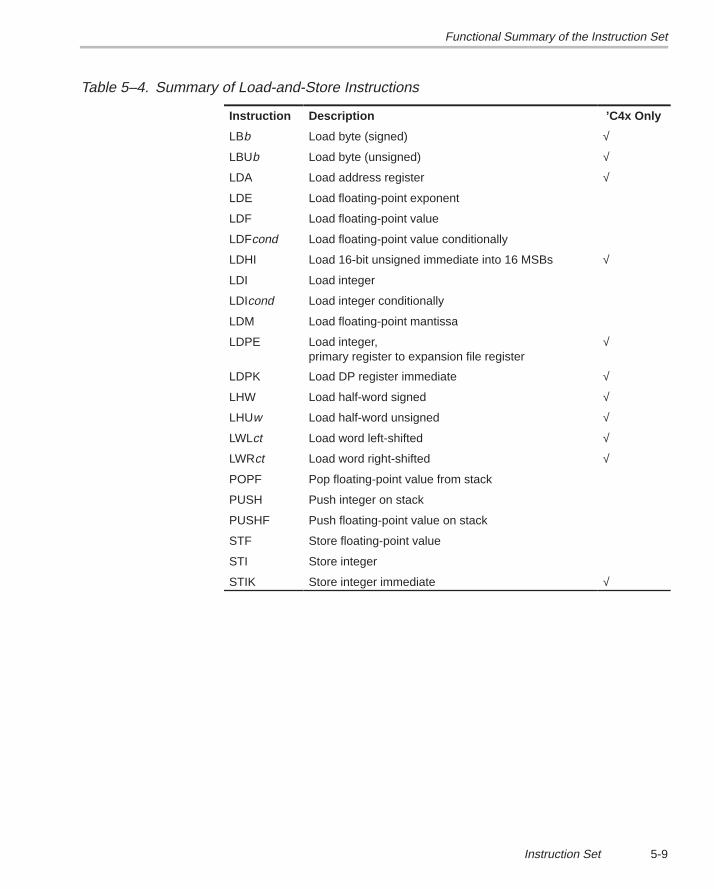
Functional Summary of the Instruction Set
5-9Instruction Set
Table 5–4. Summary of Load-and-Store Instructions
Instruction Description ’C4x Only
LBb Load byte (signed) √
LBUb Load byte (unsigned) √
LDA Load address register √
LDE Load floating-point exponent
LDF Load floating-point value
LDFcond Load floating-point value conditionally
LDHI Load 16-bit unsigned immediate into 16 MSBs √
LDI Load integer
LDIcond Load integer conditionally
LDM Load floating-point mantissa
LDPE Load integer, primary register to expansion file register
√
LDPK Load DP register immediate √
LHW Load half-word signed √
LHUw Load half-word unsigned √
LWLct Load word left-shifted √
LWRct Load word right-shifted √
POPF Pop floating-point value from stack
PUSH Push integer on stack
PUSHF Push floating-point value on stack
STF Store floating-point value
STI Store integer
STIK Store integer immediate √
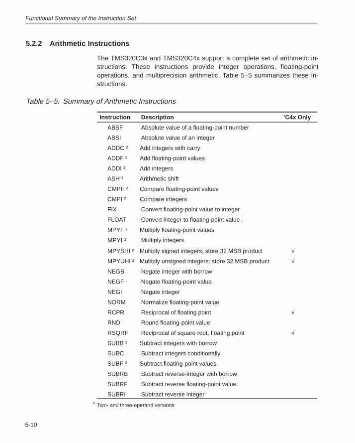
Functional Summary of the Instruction Set
5-10
5.2.2 Arithmetic Instructions
The TMS320C3x and TMS320C4x support a complete set of arithmetic in-structions. These instructions provide integer operations, floating-pointoperations, and multiprecision arithmetic. Table 5–5 summarizes these in-structions.
Table 5–5. Summary of Arithmetic Instructions
Instruction Description ’C4x Only
ABSF Absolute value of a floating-point number
ABSI Absolute value of an integer
ADDC † Add integers with carry
ADDF † Add floating-point values
ADDI † Add integers
ASH † Arithmetic shift
CMPF † Compare floating-point values
CMPI † Compare integers
FIX Convert floating-point value to integer
FLOAT Convert integer to floating-point value
MPYF † Multiply floating-point values
MPYI † Multiply integers
MPYSHI † Multiply signed integers; store 32 MSB product √
MPYUHI † Multiply unsigned integers; store 32 MSB product √
NEGB Negate integer with borrow
NEGF Negate floating-point value
NEGI Negate integer
NORM Normalize floating-point value
RCPR Reciprocal of floating point √
RND Round floating-point value
RSQRF Reciprocal of square root, floating point √
SUBB † Subtract integers with borrow
SUBC Subtract integers conditionally
SUBF † Subtract floating-point values
SUBRB Subtract reverse-integer with borrow
SUBRF Subtract reverse floating-point value
SUBRI Subtract reverse integer
† Two- and three-operand versions
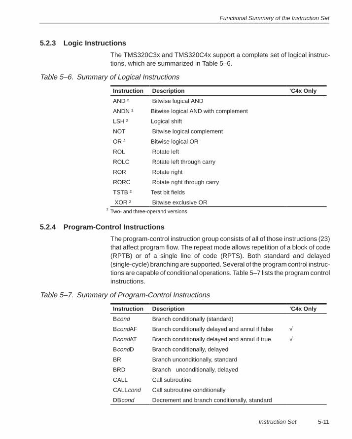
Functional Summary of the Instruction Set
5-11Instruction Set
5.2.3 Logic Instructions
The TMS320C3x and TMS320C4x support a complete set of logical instruc-tions, which are summarized in Table 5–6.
Table 5–6. Summary of Logical Instructions
Instruction Description ’C4x Only
AND † Bitwise logical AND
ANDN † Bitwise logical AND with complement
LSH † Logical shift
NOT Bitwise logical complement
OR † Bitwise logical OR
ROL Rotate left
ROLC Rotate left through carry
ROR Rotate right
RORC Rotate right through carry
TSTB † Test bit fields
XOR † Bitwise exclusive OR† Two- and three-operand versions
5.2.4 Program-Control Instructions
The program-control instruction group consists of all of those instructions (23)that affect program flow. The repeat mode allows repetition of a block of code(RPTB) or of a single line of code (RPTS). Both standard and delayed(single-cycle) branching are supported. Several of the program control instruc-tions are capable of conditional operations. Table 5–7 lists the program controlinstructions.
Table 5–7. Summary of Program-Control Instructions
Instruction Description ’C4x Only
Bcond Branch conditionally (standard)
BcondAF Branch conditionally delayed and annul if false √
BcondAT Branch conditionally delayed and annul if true √
BcondD Branch conditionally, delayed
BR Branch unconditionally, standard
BRD Branch unconditionally, delayed
CALL Call subroutine
CALLcond Call subroutine conditionally
DBcond Decrement and branch conditionally, standard
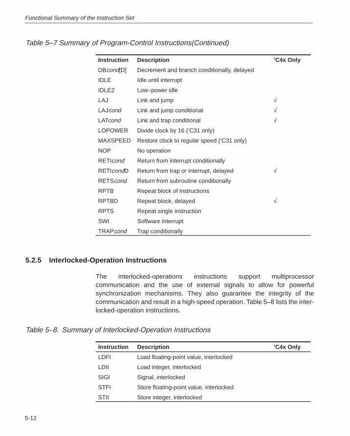
Functional Summary of the Instruction Set
5-12
Table 5–7 Summary of Program-Control Instructions(Continued)
Instruction Description ’C4x Only
DBcond[D] Decrement and branch conditionally, delayed
IDLE Idle until interrupt
IDLE2 Low–power idle
LAJ Link and jump √
LAJcond Link and jump conditional √
LATcond Link and trap conditional √
LOPOWER Divide clock by 16 (’C31 only)
MAXSPEED Restore clock to regular speed (’C31 only)
NOP No operation
RETIcond Return from interrupt conditionally
RETIcondD Return from trap or interrupt, delayed √
RETScond Return from subroutine conditionally
RPTB Repeat block of instructions
RPTBD Repeat block, delayed √
RPTS Repeat single instruction
SWI Software interrupt
TRAPcond Trap conditionally
5.2.5 Interlocked-Operation Instructions
The interlocked-operations instructions support multiprocessorcommunication and the use of external signals to allow for powerfulsynchronization mechanisms. They also guarantee the integrity of thecommunication and result in a high-speed operation. Table 5–8 lists the inter-locked-operation instructions.
Table 5–8. Summary of Interlocked-Operation Instructions
Instruction Description ’C4x Only
LDFI Load floating-point value, interlocked
LDII Load integer, interlocked
SIGI Signal, interlocked
STFI Store floating-point value, interlocked
STII Store integer, interlocked
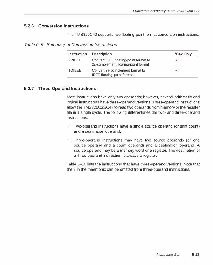
Functional Summary of the Instruction Set
5-13Instruction Set
5.2.6 Conversion Instructions
The TMS320C40 supports two floating-point format conversion instructions:
Table 5–9. Summary of Conversion Instructions
Instruction Description ’C4x Only
FRIEEE Convert IEEE floating-point format to2s-complement floating-point format
√
TOIEEE Convert 2s-complement format to IEEE floating-point format
√
5.2.7 Three-Operand Instructions
Most instructions have only two operands; however, several arithmetic andlogical instructions have three-operand versions. Three-operand instructionsallow the TMS320C3x/C4x to read two operands from memory or the registerfile in a single cycle. The following differentiates the two- and three-operandinstructions:
� Two-operand instructions have a single source operand (or shift count)and a destination operand.
� Three-operand instructions may have two source operands (or onesource operand and a count operand) and a destination operand. Asource operand may be a memory word or a register. The destination ofa three-operand instruction is always a register.
Table 5–10 lists the instructions that have three-operand versions. Note thatthe 3 in the mnemonic can be omitted from three-operand instructions.
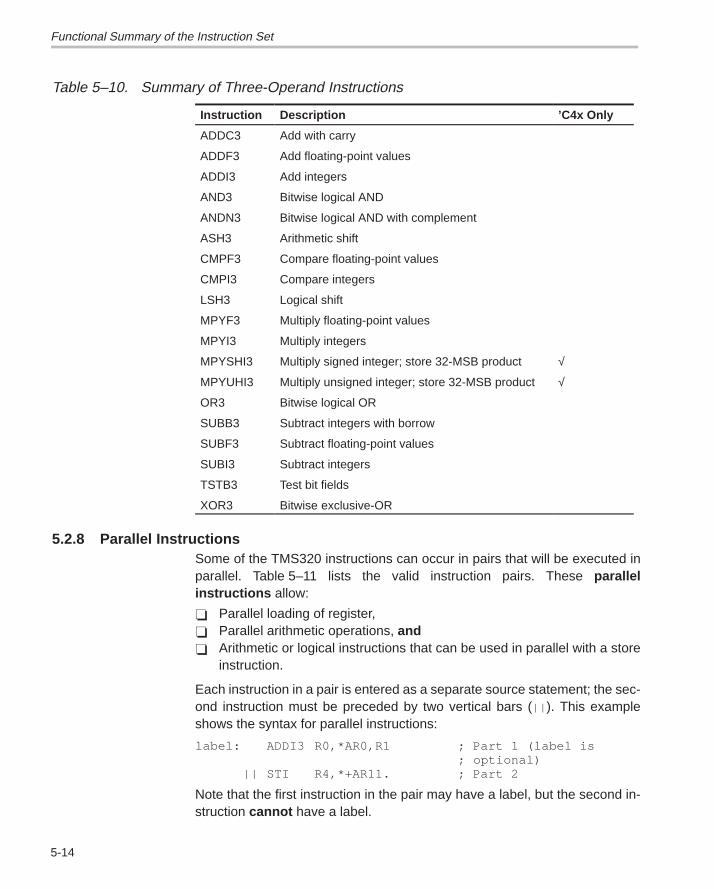
Functional Summary of the Instruction Set
5-14
Table 5–10. Summary of Three-Operand Instructions
Instruction Description ’C4x Only
ADDC3 Add with carry
ADDF3 Add floating-point values
ADDI3 Add integers
AND3 Bitwise logical AND
ANDN3 Bitwise logical AND with complement
ASH3 Arithmetic shift
CMPF3 Compare floating-point values
CMPI3 Compare integers
LSH3 Logical shift
MPYF3 Multiply floating-point values
MPYI3 Multiply integers
MPYSHI3 Multiply signed integer; store 32-MSB product √
MPYUHI3 Multiply unsigned integer; store 32-MSB product √
OR3 Bitwise logical OR
SUBB3 Subtract integers with borrow
SUBF3 Subtract floating-point values
SUBI3 Subtract integers
TSTB3 Test bit fields
XOR3 Bitwise exclusive-OR
5.2.8 Parallel InstructionsSome of the TMS320 instructions can occur in pairs that will be executed inparallel. Table 5–11 lists the valid instruction pairs. These parallelinstructions allow:
� Parallel loading of register,� Parallel arithmetic operations, and� Arithmetic or logical instructions that can be used in parallel with a store
instruction.
Each instruction in a pair is entered as a separate source statement; the sec-ond instruction must be preceded by two vertical bars (|| ). This exampleshows the syntax for parallel instructions:
label: ADDI3 R0,*AR0,R1 ; Part 1 (label is; optional)
|| STI R4,*+AR11. ; Part 2
Note that the first instruction in the pair may have a label, but the second in-struction cannot have a label.
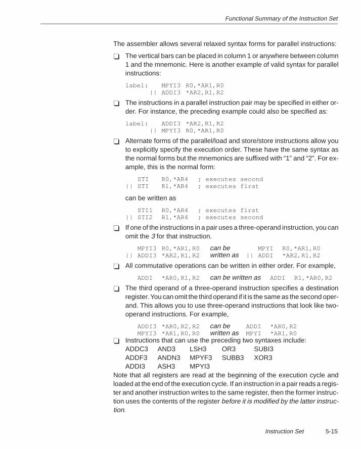
Functional Summary of the Instruction Set
5-15Instruction Set
The assembler allows several relaxed syntax forms for parallel instructions:
� The vertical bars can be placed in column 1 or anywhere between column1 and the mnemonic. Here is another example of valid syntax for parallelinstructions:
label: MPYI3 R0,*AR1,R0|| ADDI3 *AR2,R1,R2
� The instructions in a parallel instruction pair may be specified in either or-der. For instance, the preceding example could also be specified as:
label: ADDI3 *AR2,R1,R2|| MPYI3 R0,*AR1,R0
� Alternate forms of the parallel/load and store/store instructions allow youto explicitly specify the execution order. These have the same syntax asthe normal forms but the mnemonics are suffixed with “1” and “2”. For ex-ample, this is the normal form:
STI R0,*AR4 ; executes second|| STI R1,*AR4 ; executes first
can be written as
STI1 R0,*AR4 ; executes first|| STI2 R1,*AR4 ; executes second
� If one of the instructions in a pair uses a three-operand instruction, you canomit the 3 for that instruction.
MPYI3 R0,*AR1,R0 can be MPYI R0,*AR1,R0|| ADDI3 *AR2,R1,R2 written as || ADDI *AR2,R1,R2
� All commutative operations can be written in either order. For example,
ADDI *AR0,R1,R2 can be written as ADDI R1,*AR0,R2
� The third operand of a three-operand instruction specifies a destinationregister. You can omit the third operand if it is the same as the second oper-and. This allows you to use three-operand instructions that look like two-operand instructions. For example,
ADDI3 *AR0,R2,R2 can be ADDI *AR0,R2MPYI3 *AR1,R0,R0 written as MPYI *AR1,R0
� Instructions that can use the preceding two syntaxes include:ADDC3 AND3 LSH3 OR3 SUBI3ADDF3 ANDN3 MPYF3 SUBB3 XOR3ADDI3 ASH3 MPYI3
Note that all registers are read at the beginning of the execution cycle andloaded at the end of the execution cycle. If an instruction in a pair reads a regis-ter and another instruction writes to the same register, then the former instruc-tion uses the contents of the register before it is modified by the latter instruc-tion.
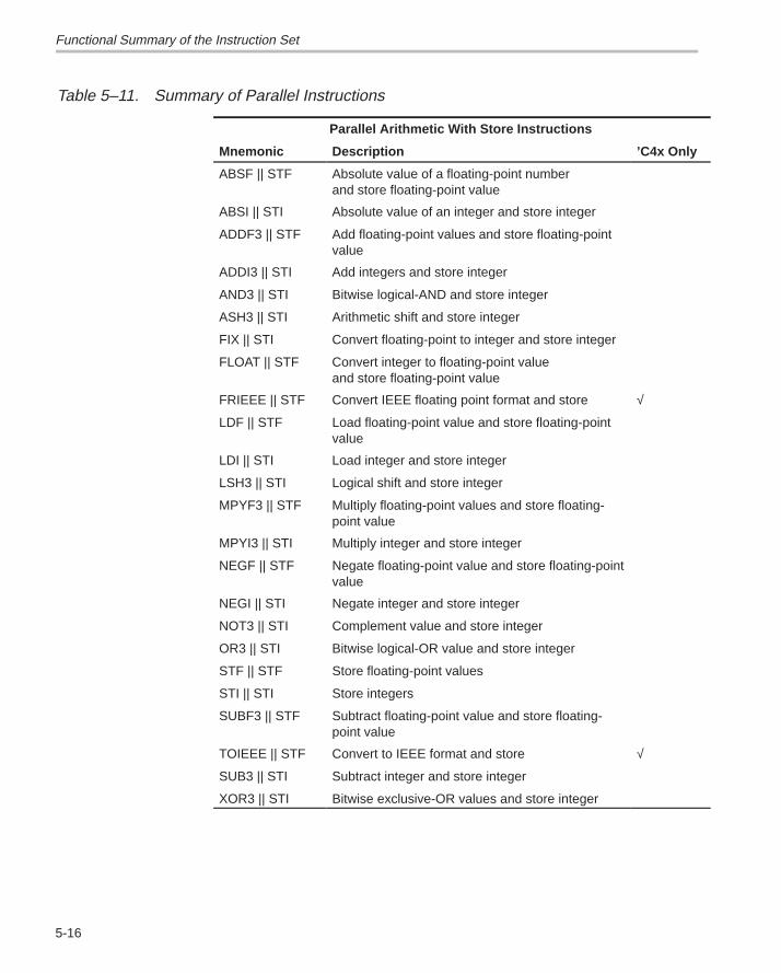
Functional Summary of the Instruction Set
5-16
Table 5–11. Summary of Parallel Instructions
Parallel Arithmetic With Store Instructions
Mnemonic Description ’C4x Only
ABSF || STF Absolute value of a floating-point number and store floating-point value
ABSI || STI Absolute value of an integer and store integer
ADDF3 || STF Add floating-point values and store floating-pointvalue
ADDI3 || STI Add integers and store integer
AND3 || STI Bitwise logical-AND and store integer
ASH3 || STI Arithmetic shift and store integer
FIX || STI Convert floating-point to integer and store integer
FLOAT || STF Convert integer to floating-point value and store floating-point value
FRIEEE || STF Convert IEEE floating point format and store √
LDF || STF Load floating-point value and store floating-pointvalue
LDI || STI Load integer and store integer
LSH3 || STI Logical shift and store integer
MPYF3 || STF Multiply floating-point values and store floating-point value
MPYI3 || STI Multiply integer and store integer
NEGF || STF Negate floating-point value and store floating-pointvalue
NEGI || STI Negate integer and store integer
NOT3 || STI Complement value and store integer
OR3 || STI Bitwise logical-OR value and store integer
STF || STF Store floating-point values
STI || STI Store integers
SUBF3 || STF Subtract floating-point value and store floating-point value
TOIEEE || STF Convert to IEEE format and store √
SUB3 || STI Subtract integer and store integer
XOR3 || STI Bitwise exclusive-OR values and store integer

Functional Summary of the Instruction Set
5-17Instruction Set
Table 5–11. Summary of Parallel Instructions (Continued)
Parallel Load Instructions
Mnemonic Description ’C4x Only
LDF || LDF Load floating-point
LDI || LDI Load integer
Parallel Multiply and Add/Subtract Instructions
Mnemonic Description ’C4x Only
MPYF3 || ADDF3 Multiply and add floating-point
MPYF3 || SUBF3 Multiply and subtract floating-point
MPYI3 || ADDI3 Multiply and add integer
MPYI3 || SUBI3 Multiply and subtract integer
Functional Summary of the Instruction Set
5-18
5.2.9 TMS320C4x-Only Instructions
Some of the instructions work only on the TMS320C4x. Table 5–12 lists theseinstructions.
Table 5–12. Summary of TMS320C4x-Only Instructions
Instruction Description
BcondAF Branch conditionally delayed and annul if false
BcondAT Branch conditionally delayed and annul if true
FRIEEE Convert from IEEE format
FRIEEE||STF Parallel FRIEEE and STF
LAJ Link and Jump (Single-cycle subroutine call)
LAJcond Link and jump conditionally (Single-cycle subroutine call)
LATcond Link and trap conditional delayed (delayed conditional trap)
LBb Load sign-extended byte
LBUb Load unsigned byte
LDA Load address register (faster than LDI for select registers)
LDEP Load integer from expansion register file to primary register file
LDHI Load 16 MSBs with 16-bit immediate
LDPE Load integer from primary register file to expansion register file
LDPK Load data-page pointer immediate
LHw Load sign-extended half-word
LHUw Load unsigned half-word
LWLct Load word left-shifted (ct = no. of bytes to shift left, 1, 2, or 3)
LWRct Load word right-shifted (ct = no. of bytes to shift right, 1, 2, or 3)
MBct Merge byte left-shifted (ct = no. of bytes to shift left, 1, 2, or 3)
MHct Merge half-word left-shifted (ct = no. of bytes to shift left)
MPYSHI Multiply signed integer and produce 32 MSBs
MPYSHI3 Multiply signed integer and produce 32 MSBs (3 operand)
MPYUHI Multiply unsigned integer and produce 32 MSBs
MPYUHI3 Multiply unsigned integer and produce 32 MSBs (3 operand)
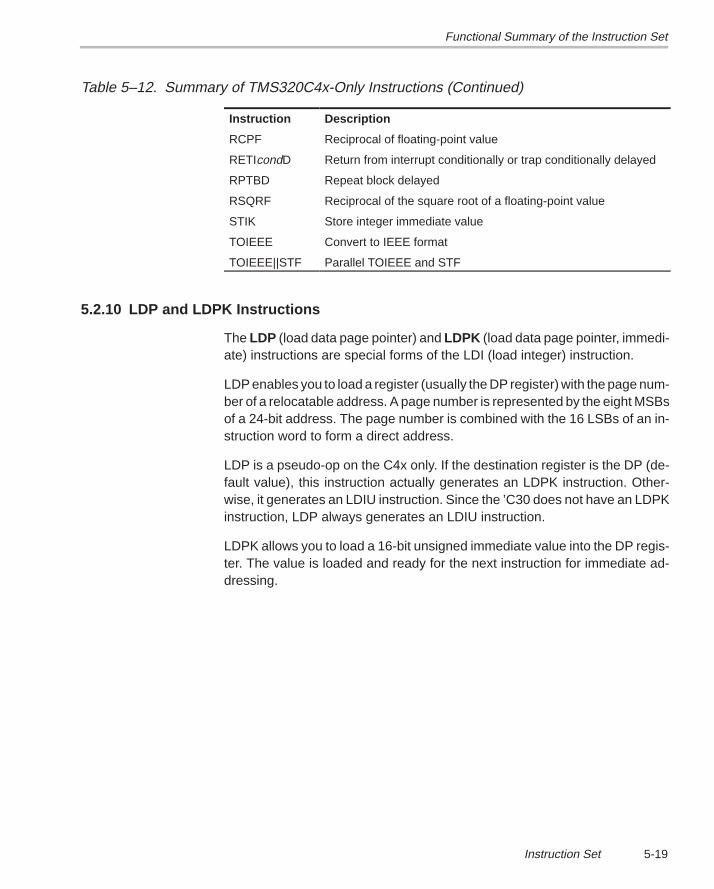
Functional Summary of the Instruction Set
5-19Instruction Set
Table 5–12. Summary of TMS320C4x-Only Instructions (Continued)
Instruction Description
RCPF Reciprocal of floating-point value
RETIcondD Return from interrupt conditionally or trap conditionally delayed
RPTBD Repeat block delayed
RSQRF Reciprocal of the square root of a floating-point value
STIK Store integer immediate value
TOIEEE Convert to IEEE format
TOIEEE||STF Parallel TOIEEE and STF
5.2.10 LDP and LDPK Instructions
The LDP (load data page pointer) and LDPK (load data page pointer, immedi-ate) instructions are special forms of the LDI (load integer) instruction.
LDP enables you to load a register (usually the DP register) with the page num-ber of a relocatable address. A page number is represented by the eight MSBsof a 24-bit address. The page number is combined with the 16 LSBs of an in-struction word to form a direct address.
LDP is a pseudo-op on the C4x only. If the destination register is the DP (de-fault value), this instruction actually generates an LDPK instruction. Other-wise, it generates an LDIU instruction. Since the ’C30 does not have an LDPKinstruction, LDP always generates an LDIU instruction.
LDPK allows you to load a 16-bit unsigned immediate value into the DP regis-ter. The value is loaded and ready for the next instruction for immediate ad-dressing.
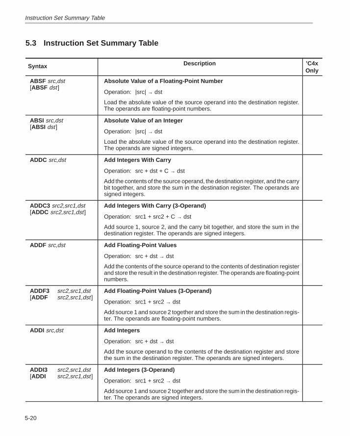
Instruction Set Summary Table
5-20
5.3 Instruction Set Summary Table
Syntax Description ’C4xOnly
ABSF src,dst[ABSF dst ]
Absolute Value of a Floating-Point Number
Operation: |src| → dst
Load the absolute value of the source operand into the destination register.The operands are floating-point numbers.
ABSI src,dst[ABSI dst ]
Absolute Value of an Integer
Operation: |src| → dst
Load the absolute value of the source operand into the destination register.The operands are signed integers.
ADDC src,dst Add Integers With Carry
Operation: src + dst + C → dst
Add the contents of the source operand, the destination register, and the carrybit together, and store the sum in the destination register. The operands aresigned integers.
ADDC3 src2,src1,dst[ADDC src2,src1,dst ]
Add Integers With Carry (3-Operand)
Operation: src1 + src2 + C → dst
Add source 1, source 2, and the carry bit together, and store the sum in thedestination register. The operands are signed integers.
ADDF src,dst Add Floating-Point Values
Operation: src + dst → dst
Add the contents of the source operand to the contents of destination registerand store the result in the destination register. The operands are floating-pointnumbers.
ADDF3 src2,src1,dst[ADDF src2,src1,dst ]
Add Floating-Point Values (3-Operand)
Operation: src1 + src2 → dst
Add source 1 and source 2 together and store the sum in the destination regis-ter. The operands are floating-point numbers.
ADDI src,dst Add Integers
Operation: src + dst → dst
Add the source operand to the contents of the destination register and storethe sum in the destination register. The operands are signed integers.
ADDI3 src2,src1,dst[ADDI src2,src1,dst ]
Add Integers (3-Operand)
Operation: src1 + src2 → dst
Add source 1 and source 2 together and store the sum in the destination regis-ter. The operands are signed integers.
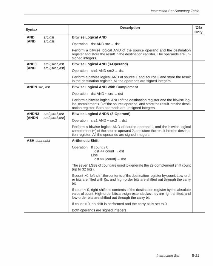
Instruction Set Summary Table
5-21Instruction Set
Syntax ’C4xOnly
Description
AND src,dst[AND src,dst ]
Bitwise Logical AND
Operation: dst AND src → dst
Perform a bitwise logical AND of the source operand and the destinationregister and store the result in the destination register. The operands are un-signed integers.
AND3 src2,src1,dst[AND src2,src1,dst ]
Bitwise Logical AND (3-Operand)
Operation: src1 AND src2 → dst
Perform a bitwise logical AND of source 1 and source 2 and store the resultin the destination register. All the operands are signed integers.
ANDN src, dst Bitwise Logical AND With Complement
Operation: dst AND ~ src → dst
Perform a bitwise logical AND of the destination register and the bitwise log-ical complement (~) of the source operand, and store the result into the desti-nation register. Both operands are unsigned integers.
ANDN3 src2,src1,dst[ANDN src2,src1,dst ]
Bitwise Logical ANDN (3-Operand)
Operation: src1 AND ~ src2 → dst
Perform a bitwise logical AND of source operand 1 and the bitwise logicalcomplement (~) of the source operand 2, and store the result into the destina-tion register. All the operands are signed integers.
ASH count,dst Arithmetic Shift
Operation: If count ≥ 0dst << count → dst
Else dst >> |count| → dst
The seven LSBs of count are used to generate the 2s-complement shift count(up to 32 bits).
If count > 0, left-shift the contents of the destination register by count. Low-ord-er bits are filled with 0s, and high-order bits are shifted out through the carrybit.
If count < 0, right-shift the contents of the destination register by the absolutevalue of count. High-order bits are sign-extended as they are right-shifted, andlow-order bits are shifted out through the carry bit.
If count = 0, no shift is performed and the carry bit is set to 0.
Both operands are signed integers.
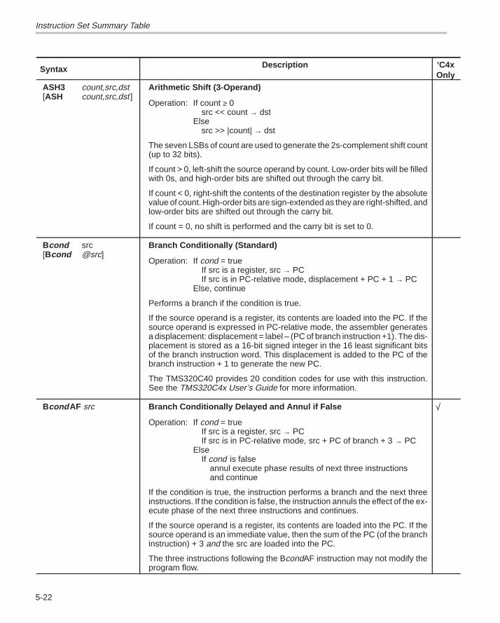
Instruction Set Summary Table
5-22
Syntax ’C4xOnly
Description
ASH3 count,src,dst[ASH count,src,dst ]
Arithmetic Shift (3-Operand)
Operation: If count ≥ 0src << count → dst
Else src >> |count| → dst
The seven LSBs of count are used to generate the 2s-complement shift count(up to 32 bits).
If count > 0, left-shift the source operand by count. Low-order bits will be filledwith 0s, and high-order bits are shifted out through the carry bit.
If count < 0, right-shift the contents of the destination register by the absolutevalue of count. High-order bits are sign-extended as they are right-shifted, andlow-order bits are shifted out through the carry bit.
If count = 0, no shift is performed and the carry bit is set to 0.
Bcond src[Bcond @src]
Branch Conditionally (Standard)
Operation: If cond = trueIf src is a register, src → PCIf src is in PC-relative mode, displacement + PC + 1 → PC
Else, continue
Performs a branch if the condition is true.
If the source operand is a register, its contents are loaded into the PC. If thesource operand is expressed in PC-relative mode, the assembler generatesa displacement: displacement = label – (PC of branch instruction +1). The dis-placement is stored as a 16-bit signed integer in the 16 least significant bitsof the branch instruction word. This displacement is added to the PC of thebranch instruction + 1 to generate the new PC.
The TMS320C40 provides 20 condition codes for use with this instruction.See the TMS320C4x User’s Guide for more information.
Bcond AF src Branch Conditionally Delayed and Annul if False
Operation: If cond = trueIf src is a register, src → PCIf src is in PC-relative mode, src + PC of branch + 3 → PC
ElseIf cond is false
annul execute phase results of next three instructionsand continue
If the condition is true, the instruction performs a branch and the next threeinstructions. If the condition is false, the instruction annuls the effect of the ex-ecute phase of the next three instructions and continues.
If the source operand is a register, its contents are loaded into the PC. If thesource operand is an immediate value, then the sum of the PC (of the branchinstruction) + 3 and the src are loaded into the PC.
The three instructions following the BcondAF instruction may not modify theprogram flow.
√
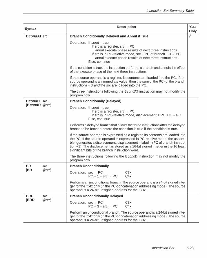
Instruction Set Summary Table
5-23Instruction Set
Syntax ’C4xOnly
Description
Bcond AT src Branch Conditionally Delayed and Annul if True
Operation: If cond = trueIf src is a register, src → PC
annul execute phase results of next three instructionsIf src is in PC-relative mode, src + PC of branch + 3 → PC
annul execute phase results of next three instructionsElse, continue
If the condition is true, the instruction performs a branch and annuls the effectof the execute phase of the next three instructions.
If the source operand is a register, its contents are loaded into the PC. If thesource operand is an immediate value, then the sum of the PC (of the branchinstruction) + 3 and the src are loaded into the PC.
The three instructions following the BcondAT instruction may not modify theprogram flow.
√
Bcond D src[Bcond D @src]
Branch Conditionally (Delayed)
Operation: If cond = trueIf src is a register, src → PCIf src is in PC-relative mode, displacement + PC + 3 → PC
Else, continue
Performs a delayed branch that allows the three instructions after the delayedbranch to be fetched before the condition is true if the condition is true.
If the source operand is expressed as a register, its contents are loaded intothe PC. If the source operand is expressed in PC-relative mode, the assem-bler generates a displacement: displacement = label – (PC of branch instruc-tion +1). The displacement is stored as a 16-bit signed integer in the 16 leastsignificant bits of the branch instruction word.
The three instructions following the BcondD instruction may not modify theprogram flow.
BR src[BR @src]
Branch Unconditionally
Operation: src → PC C3xPC + 1 + src → PC C4x
Performs an unconditional branch. The source operand is a 24-bit signed inte-ger for the ’C4x only (in the PC-concatenation addressing mode). The sourceoperand is a 24-bit unsigned address for the ’C3x.
BRD src[BRD @src]
Branch Unconditionally Delayed
Operation: src → PC C3xPC + 3 + src → PC C4x
Perform an unconditional branch. The source operand is a 24-bit signed inte-ger for the ’C4x only (in the PC-concatenation addressing mode). The sourceoperand is a 24-bit unsigned address for the ’C3x.
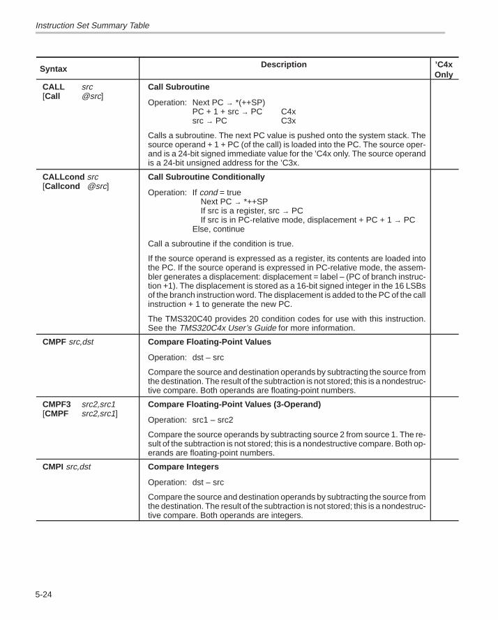
Instruction Set Summary Table
5-24
Syntax ’C4xOnly
Description
CALL src[Call @src]
Call Subroutine
Operation: Next PC → *(++SP)PC + 1 + src → PC C4xsrc → PC C3x
Calls a subroutine. The next PC value is pushed onto the system stack. Thesource operand + 1 + PC (of the call) is loaded into the PC. The source oper-and is a 24-bit signed immediate value for the ’C4x only. The source operandis a 24-bit unsigned address for the ’C3x.
CALLcond src[Callcond @src]
Call Subroutine Conditionally
Operation: If cond = trueNext PC → *++SPIf src is a register, src → PCIf src is in PC-relative mode, displacement + PC + 1 → PC
Else, continue
Call a subroutine if the condition is true.
If the source operand is expressed as a register, its contents are loaded intothe PC. If the source operand is expressed in PC-relative mode, the assem-bler generates a displacement: displacement = label – (PC of branch instruc-tion +1). The displacement is stored as a 16-bit signed integer in the 16 LSBsof the branch instruction word. The displacement is added to the PC of the callinstruction + 1 to generate the new PC.
The TMS320C40 provides 20 condition codes for use with this instruction.See the TMS320C4x User’s Guide for more information.
CMPF src,dst Compare Floating-Point Values
Operation: dst – src
Compare the source and destination operands by subtracting the source fromthe destination. The result of the subtraction is not stored; this is a nondestruc-tive compare. Both operands are floating-point numbers.
CMPF3 src2,src1[CMPF src2,src1]
Compare Floating-Point Values (3-Operand)
Operation: src1 – src2
Compare the source operands by subtracting source 2 from source 1. The re-sult of the subtraction is not stored; this is a nondestructive compare. Both op-erands are floating-point numbers.
CMPI src,dst Compare Integers
Operation: dst – src
Compare the source and destination operands by subtracting the source fromthe destination. The result of the subtraction is not stored; this is a nondestruc-tive compare. Both operands are integers.
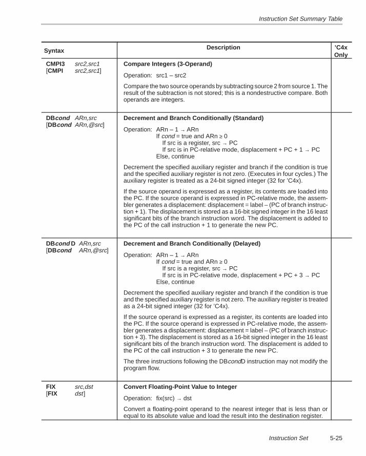
Instruction Set Summary Table
5-25Instruction Set
Syntax ’C4xOnly
Description
CMPI3 src2,src1[CMPI src2,src1]
Compare Integers (3-Operand)
Operation: src1 – src2
Compare the two source operands by subtracting source 2 from source 1. Theresult of the subtraction is not stored; this is a nondestructive compare. Bothoperands are integers.
DBcond ARn,src[DBcond ARn,@src]
Decrement and Branch Conditionally (Standard)
Operation: ARn – 1 → ARnIf cond = true and ARn ≥ 0
If src is a register, src → PCIf src is in PC-relative mode, displacement + PC + 1 → PC
Else, continue
Decrement the specified auxiliary register and branch if the condition is trueand the specified auxiliary register is not zero. (Executes in four cycles.) Theauxiliary register is treated as a 24-bit signed integer (32 for ’C4x).
If the source operand is expressed as a register, its contents are loaded intothe PC. If the source operand is expressed in PC-relative mode, the assem-bler generates a displacement: displacement = label – (PC of branch instruc-tion + 1). The displacement is stored as a 16-bit signed integer in the 16 leastsignificant bits of the branch instruction word. The displacement is added tothe PC of the call instruction + 1 to generate the new PC.
DBcond D ARn,src[DBcond ARn,@src]
Decrement and Branch Conditionally (Delayed)
Operation: ARn – 1 → ARnIf cond = true and ARn ≥ 0
If src is a register, src → PCIf src is in PC-relative mode, displacement + PC + 3 → PC
Else, continue
Decrement the specified auxiliary register and branch if the condition is trueand the specified auxiliary register is not zero. The auxiliary register is treatedas a 24-bit signed integer (32 for ’C4x).
If the source operand is expressed as a register, its contents are loaded intothe PC. If the source operand is expressed in PC-relative mode, the assem-bler generates a displacement: displacement = label – (PC of branch instruc-tion + 3). The displacement is stored as a 16-bit signed integer in the 16 leastsignificant bits of the branch instruction word. The displacement is added tothe PC of the call instruction + 3 to generate the new PC.
The three instructions following the DBcondD instruction may not modify theprogram flow.
FIX src,dst[FIX dst ]
Convert Floating-Point Value to Integer
Operation: fix(src) → dst
Convert a floating-point operand to the nearest integer that is less than orequal to its absolute value and load the result into the destination register.
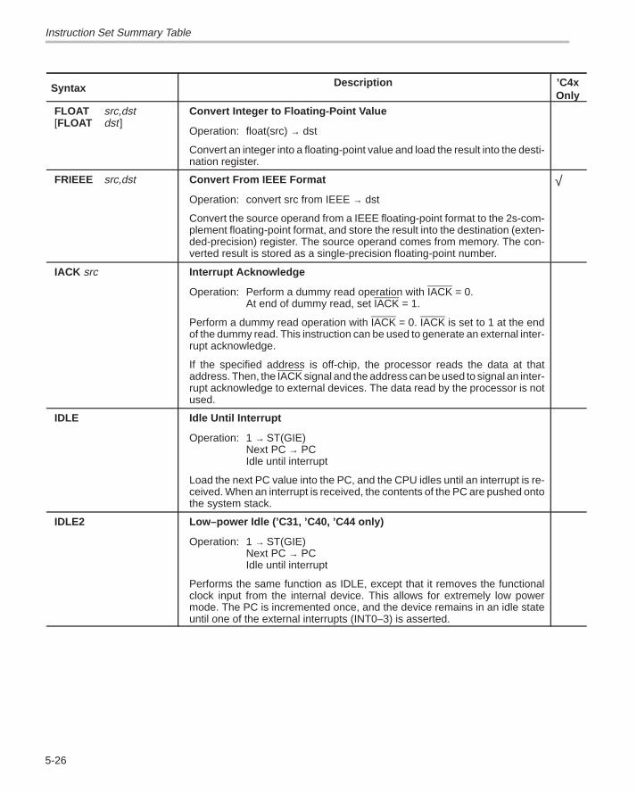
Instruction Set Summary Table
5-26
Syntax ’C4xOnly
Description
FLOAT src,dst[FLOAT dst ]
Convert Integer to Floating-Point Value
Operation: float(src) → dst
Convert an integer into a floating-point value and load the result into the desti-nation register.
FRIEEE src,dst Convert From IEEE Format
Operation: convert src from IEEE → dst
Convert the source operand from a IEEE floating-point format to the 2s-com-plement floating-point format, and store the result into the destination (exten-ded-precision) register. The source operand comes from memory. The con-verted result is stored as a single-precision floating-point number.
√
IACK src Interrupt Acknowledge
Operation: Perform a dummy read operation with IACK = 0.At end of dummy read, set IACK = 1.
Perform a dummy read operation with IACK = 0. IACK is set to 1 at the endof the dummy read. This instruction can be used to generate an external inter-rupt acknowledge.
If the specified address is off-chip, the processor reads the data at thataddress. Then, the IACK signal and the address can be used to signal an inter-rupt acknowledge to external devices. The data read by the processor is notused.
IDLE Idle Until Interrupt
Operation: 1 → ST(GIE)Next PC → PCIdle until interrupt
Load the next PC value into the PC, and the CPU idles until an interrupt is re-ceived. When an interrupt is received, the contents of the PC are pushed ontothe system stack.
IDLE2 Low–power Idle (’C31, ’C40, ’C44 only)
Operation: 1 → ST(GIE)Next PC → PCIdle until interrupt
Performs the same function as IDLE, except that it removes the functionalclock input from the internal device. This allows for extremely low powermode. The PC is incremented once, and the device remains in an idle stateuntil one of the external interrupts (INT0–3) is asserted.
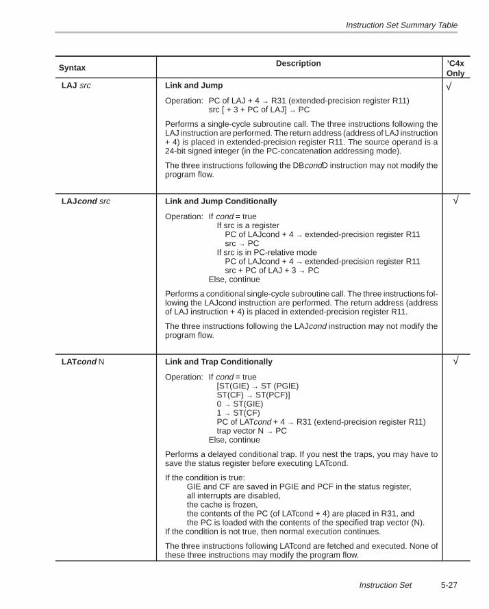
Instruction Set Summary Table
5-27Instruction Set
Syntax ’C4xOnly
Description
LAJ src Link and Jump
Operation: PC of LAJ + 4 → R31 (extended-precision register R11)src [ + 3 + PC of LAJ] → PC
Performs a single-cycle subroutine call. The three instructions following theLAJ instruction are performed. The return address (address of LAJ instruction+ 4) is placed in extended-precision register R11. The source operand is a24-bit signed integer (in the PC-concatenation addressing mode).
The three instructions following the DBcondD instruction may not modify theprogram flow.
√
LAJ cond src Link and Jump Conditionally
Operation: If cond = trueIf src is a register
PC of LAJcond + 4 → extended-precision register R11src → PC
If src is in PC-relative modePC of LAJcond + 4 → extended-precision register R11src + PC of LAJ + 3 → PC
Else, continue
Performs a conditional single-cycle subroutine call. The three instructions fol-lowing the LAJcond instruction are performed. The return address (addressof LAJ instruction + 4) is placed in extended-precision register R11.
The three instructions following the LAJcond instruction may not modify theprogram flow.
√
LATcond N Link and Trap Conditionally
Operation: If cond = true[ST(GIE) → ST (PGIE)ST(CF) → ST(PCF)]0 → ST(GIE)1 → ST(CF)PC of LATcond + 4 → R31 (extend-precision register R11)trap vector N → PC
Else, continue
Performs a delayed conditional trap. If you nest the traps, you may have tosave the status register before executing LATcond.
If the condition is true:GIE and CF are saved in PGIE and PCF in the status register,all interrupts are disabled, the cache is frozen, the contents of the PC (of LATcond + 4) are placed in R31, andthe PC is loaded with the contents of the specified trap vector (N).
If the condition is not true, then normal execution continues.
The three instructions following LATcond are fetched and executed. None ofthese three instructions may modify the program flow.
√
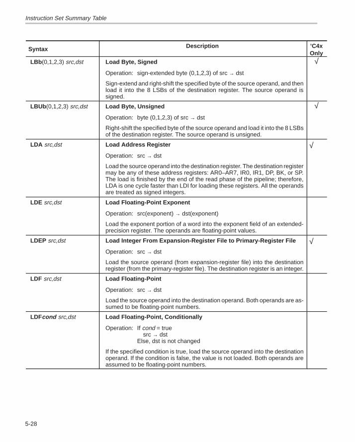
Instruction Set Summary Table
5-28
Syntax ’C4xOnly
Description
LBb (0,1,2,3) src,dst Load Byte, Signed
Operation: sign-extended byte (0,1,2,3) of src → dst
Sign-extend and right-shift the specified byte of the source operand, and thenload it into the 8 LSBs of the destination register. The source operand issigned.
√
LBUb (0,1,2,3) src,dst Load Byte, Unsigned
Operation: byte (0,1,2,3) of src → dst
Right-shift the specified byte of the source operand and load it into the 8 LSBsof the destination register. The source operand is unsigned.
√
LDA src,dst Load Address Register
Operation: src → dst
Load the source operand into the destination register. The destination registermay be any of these address registers: AR0–AR7, IR0, IR1, DP, BK, or SP.The load is finished by the end of the read phase of the pipeline; therefore,LDA is one cycle faster than LDI for loading these registers. All the operandsare treated as signed integers.
√
LDE src,dst Load Floating-Point Exponent
Operation: src(exponent) → dst(exponent)
Load the exponent portion of a word into the exponent field of an extended-precision register. The operands are floating-point values.
LDEP src,dst Load Integer From Expansion-Register File to Primary-Register File
Operation: src → dst
Load the source operand (from expansion-register file) into the destinationregister (from the primary-register file). The destination register is an integer.
√
LDF src,dst Load Floating-Point
Operation: src → dst
Load the source operand into the destination operand. Both operands are as-sumed to be floating-point numbers.
LDFcond src,dst Load Floating-Point, Conditionally
Operation: If cond = truesrc → dst
Else, dst is not changed
If the specified condition is true, load the source operand into the destinationoperand. If the condition is false, the value is not loaded. Both operands areassumed to be floating-point numbers.
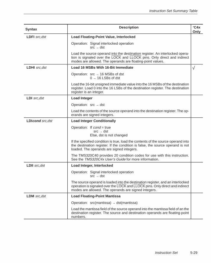
Instruction Set Summary Table
5-29Instruction Set
Syntax ’C4xOnly
Description
LDFI src,dst Load Floating-Point Value, Interlocked
Operation: Signal interlocked operationsrc → dst
Load the source operand into the destination register. An interlocked opera-tion is signaled over the LOCK and LLOCK pins. Only direct and indirectmodes are allowed. The operands are floating-point values.
LDHI src,dst Load 16 MSBs With 16-Bit Immediate
Operation: src → 16 MSBs of dst0 → 16 LSBs of dst
Load the 16-bit unsigned immediate value into the 16 MSBs of the destinationregister. Load 0 into the 16 LSBs of the destination register. The destinationregister is an integer.
√
LDI src,dst Load Integer
Operation: src → dst
Load the contents of the source operand into the destination register. The op-erands are signed integers.
LDIcond src,dst Load Integer Conditionally
Operation: If cond = truesrc → dst
Else, dst is not changed
If the specified condition is true, load the contents of the source operand intothe destination register. If the condition is false, the source operand is notloaded. The operands are signed integers.
The TMS320C40 provides 20 condition codes for use with this instruction.See the TMS320C4x User’s Guide for more information.
LDII src,dst Load Integer, Interlocked
Operation: Signal interlocked operationsrc → dst
The source operand is loaded into the destination register, and an interlockedoperation is signaled over the LOCK and LLOCK pins. Only direct and indirectmodes are allowed. The operands are signed integers.
LDM src,dst Load Floating-Point Mantissa
Operation: src(mantissa) → dst(mantissa)
Load the mantissa field of the source operand into the mantissa field of an thedestination register. The source and destination operands are floating-pointnumbers.
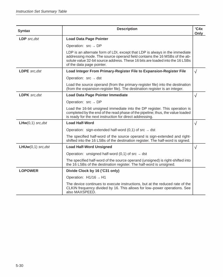
Instruction Set Summary Table
5-30
Syntax ’C4xOnly
Description
LDP src,dst Load Data Page Pointer
Operation: src → DP
LDP is an alternate form of LDI, except that LDP is always in the immediateaddressing mode. The source operand field contains the 16 MSBs of the ab-solute value 32-bit source address. These 16 bits are loaded into the 16 LSBsof the data page pointer.
LDPE src,dst Load Integer From Primary-Register File to Expansion-Register File
Operation: src → dst
Load the source operand (from the primary-register file) into the destination(from the expansion-register file). The destination register is an integer.
√
LDPK src,dst Load Data Page Pointer Immediate
Operation: src → DP
Load the 16-bit unsigned immediate into the DP register. This operation iscompleted by the end of the read phase of the pipeline; thus, the value loadedis ready for the next instruction for direct addressing.
√
LHw (0,1) src,dst Load Half-Word
Operation: sign-extended half-word (0,1) of src → dst
The specified half-word of the source operand is sign-extended and right-shifted into the 16 LSBs of the destination register. The half-word is signed.
√
LHUw (0,1) src,dst Load Half-Word Unsigned
Operation: unsigned half-word (0,1) of src → dst
The specified half-word of the source operand (unsigned) is right-shifted intothe 16 LSBs of the destination register. The half-word is unsigned.
√
LOPOWER Divide Clock by 16 (’C31 only)
Operation: H1/16 → H1
The device continues to execute instructions, but at the reduced rate of theCLKIN frequency divided by 16. This allows for low–power operations. Seealso MAXSPEED.
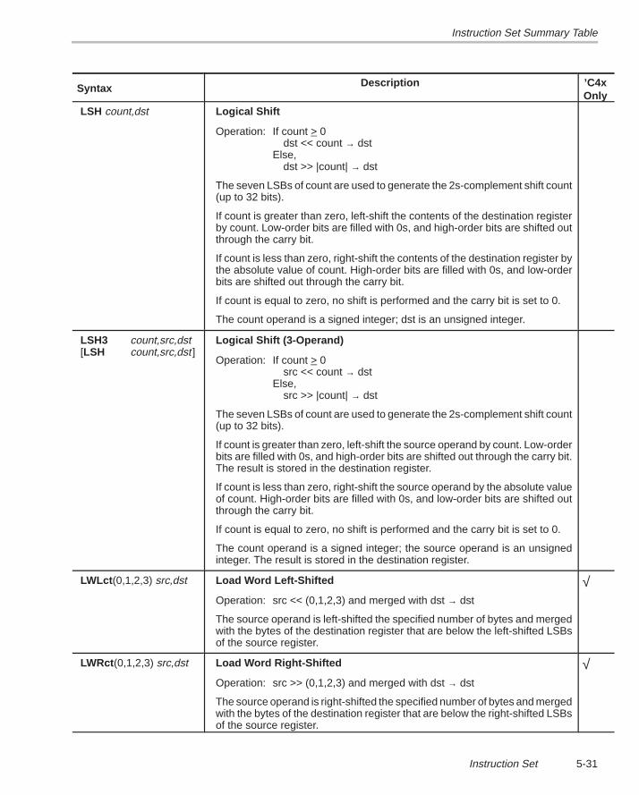
Instruction Set Summary Table
5-31Instruction Set
Syntax ’C4xOnly
Description
LSH count,dst Logical Shift
Operation: If count > 0dst << count → dst
Else, dst >> |count| → dst
The seven LSBs of count are used to generate the 2s-complement shift count(up to 32 bits).
If count is greater than zero, left-shift the contents of the destination registerby count. Low-order bits are filled with 0s, and high-order bits are shifted outthrough the carry bit.
If count is less than zero, right-shift the contents of the destination register bythe absolute value of count. High-order bits are filled with 0s, and low-orderbits are shifted out through the carry bit.
If count is equal to zero, no shift is performed and the carry bit is set to 0.
The count operand is a signed integer; dst is an unsigned integer.
LSH3 count,src,dst[LSH count,src,dst ]
Logical Shift (3-Operand)
Operation: If count > 0src << count → dst
Else, src >> |count| → dst
The seven LSBs of count are used to generate the 2s-complement shift count(up to 32 bits).
If count is greater than zero, left-shift the source operand by count. Low-orderbits are filled with 0s, and high-order bits are shifted out through the carry bit.The result is stored in the destination register.
If count is less than zero, right-shift the source operand by the absolute valueof count. High-order bits are filled with 0s, and low-order bits are shifted outthrough the carry bit.
If count is equal to zero, no shift is performed and the carry bit is set to 0.
The count operand is a signed integer; the source operand is an unsignedinteger. The result is stored in the destination register.
LWLct (0,1,2,3) src,dst Load Word Left-Shifted
Operation: src << (0,1,2,3) and merged with dst → dst
The source operand is left-shifted the specified number of bytes and mergedwith the bytes of the destination register that are below the left-shifted LSBsof the source register.
√
LWRct (0,1,2,3) src,dst Load Word Right-Shifted
Operation: src >> (0,1,2,3) and merged with dst → dst
The source operand is right-shifted the specified number of bytes and mergedwith the bytes of the destination register that are below the right-shifted LSBsof the source register.
√
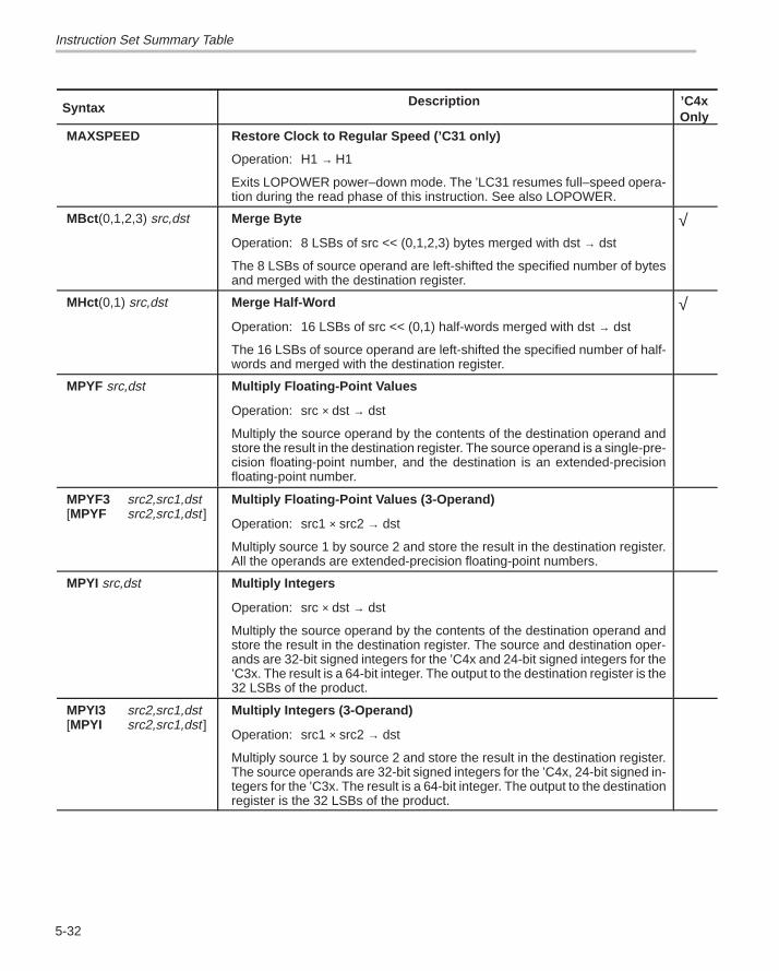
Instruction Set Summary Table
5-32
Syntax ’C4xOnly
Description
MAXSPEED Restore Clock to Regular Speed (’C31 only)
Operation: H1 → H1
Exits LOPOWER power–down mode. The ’LC31 resumes full–speed opera-tion during the read phase of this instruction. See also LOPOWER.
MBct (0,1,2,3) src,dst Merge Byte
Operation: 8 LSBs of src << (0,1,2,3) bytes merged with dst → dst
The 8 LSBs of source operand are left-shifted the specified number of bytesand merged with the destination register.
√
MHct (0,1) src,dst Merge Half-Word
Operation: 16 LSBs of src << (0,1) half-words merged with dst → dst
The 16 LSBs of source operand are left-shifted the specified number of half-words and merged with the destination register.
√
MPYF src,dst Multiply Floating-Point Values
Operation: src × dst → dst
Multiply the source operand by the contents of the destination operand andstore the result in the destination register. The source operand is a single-pre-cision floating-point number, and the destination is an extended-precisionfloating-point number.
MPYF3 src2,src1,dst[MPYF src2,src1,dst ]
Multiply Floating-Point Values (3-Operand)
Operation: src1 × src2 → dst
Multiply source 1 by source 2 and store the result in the destination register.All the operands are extended-precision floating-point numbers.
MPYI src,dst Multiply Integers
Operation: src × dst → dst
Multiply the source operand by the contents of the destination operand andstore the result in the destination register. The source and destination oper-ands are 32-bit signed integers for the ’C4x and 24-bit signed integers for the’C3x. The result is a 64-bit integer. The output to the destination register is the32 LSBs of the product.
MPYI3 src2,src1,dst[MPYI src2,src1,dst ]
Multiply Integers (3-Operand)
Operation: src1 × src2 → dst
Multiply source 1 by source 2 and store the result in the destination register.The source operands are 32-bit signed integers for the ’C4x, 24-bit signed in-tegers for the ’C3x. The result is a 64-bit integer. The output to the destinationregister is the 32 LSBs of the product.
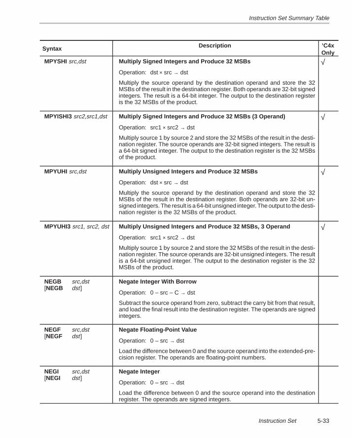
Instruction Set Summary Table
5-33Instruction Set
Syntax ’C4xOnly
Description
MPYSHI src,dst Multiply Signed Integers and Produce 32 MSBs
Operation: dst × src → dst
Multiply the source operand by the destination operand and store the 32MSBs of the result in the destination register. Both operands are 32-bit signedintegers. The result is a 64-bit integer. The output to the destination registeris the 32 MSBs of the product.
√
MPYISHI3 src2,src1,dst Multiply Signed Integers and Produce 32 MSBs (3 Operand)
Operation: src1 × src2 → dst
Multiply source 1 by source 2 and store the 32 MSBs of the result in the desti-nation register. The source operands are 32-bit signed integers. The result isa 64-bit signed integer. The output to the destination register is the 32 MSBsof the product.
√
MPYUHI src,dst Multiply Unsigned Integers and Produce 32 MSBs
Operation: dst × src → dst
Multiply the source operand by the destination operand and store the 32MSBs of the result in the destination register. Both operands are 32-bit un-signed integers. The result is a 64-bit unsigned integer. The output to the desti-nation register is the 32 MSBs of the product.
√
MPYUHI3 src1, src2, dst Multiply Unsigned Integers and Produce 32 MSBs, 3 Operand
Operation: src1 × src2 → dst
Multiply source 1 by source 2 and store the 32 MSBs of the result in the desti-nation register. The source operands are 32-bit unsigned integers. The resultis a 64-bit unsigned integer. The output to the destination register is the 32MSBs of the product.
√
NEGB src,dst[NEGB dst ]
Negate Integer With Borrow
Operation: 0 – src – C → dst
Subtract the source operand from zero, subtract the carry bit from that result,and load the final result into the destination register. The operands are signedintegers.
NEGF src,dst[NEGF dst ]
Negate Floating-Point Value
Operation: 0 – src → dst
Load the difference between 0 and the source operand into the extended-pre-cision register. The operands are floating-point numbers.
NEGI src,dst[NEGI dst ]
Negate Integer
Operation: 0 – src → dst
Load the difference between 0 and the source operand into the destinationregister. The operands are signed integers.
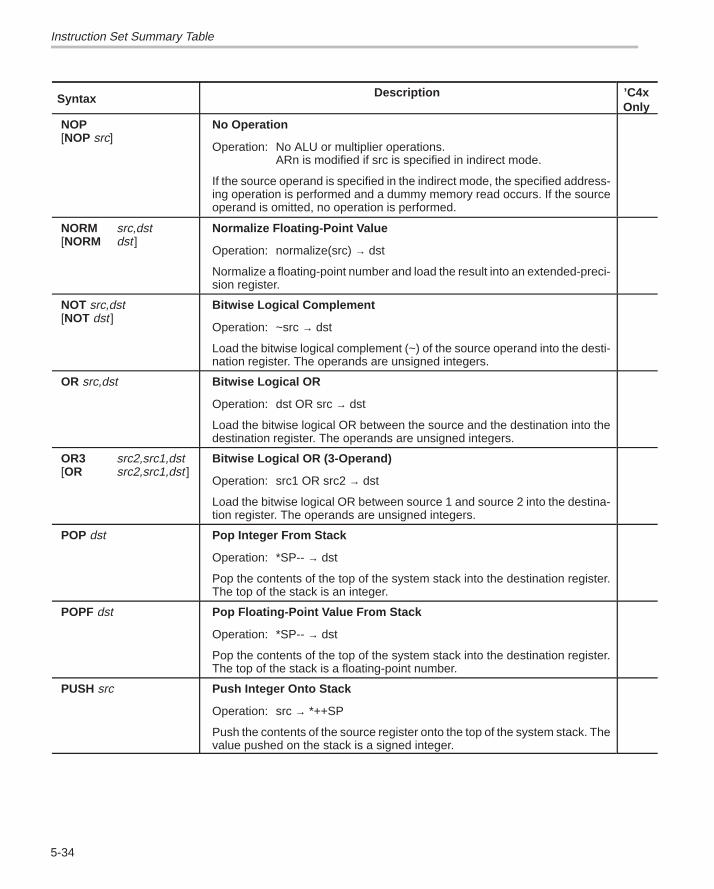
Instruction Set Summary Table
5-34
Syntax ’C4xOnly
Description
NOP[NOP src]
No Operation
Operation: No ALU or multiplier operations.ARn is modified if src is specified in indirect mode.
If the source operand is specified in the indirect mode, the specified address-ing operation is performed and a dummy memory read occurs. If the sourceoperand is omitted, no operation is performed.
NORM src,dst[NORM dst ]
Normalize Floating-Point Value
Operation: normalize(src) → dst
Normalize a floating-point number and load the result into an extended-preci-sion register.
NOT src,dst[NOT dst ]
Bitwise Logical Complement
Operation: ~src → dst
Load the bitwise logical complement (~) of the source operand into the desti-nation register. The operands are unsigned integers.
OR src,dst Bitwise Logical OR
Operation: dst OR src → dst
Load the bitwise logical OR between the source and the destination into thedestination register. The operands are unsigned integers.
OR3 src2,src1,dst[OR src2,src1,dst ]
Bitwise Logical OR (3-Operand)
Operation: src1 OR src2 → dst
Load the bitwise logical OR between source 1 and source 2 into the destina-tion register. The operands are unsigned integers.
POP dst Pop Integer From Stack
Operation: *SP-- → dst
Pop the contents of the top of the system stack into the destination register.The top of the stack is an integer.
POPF dst Pop Floating-Point Value From Stack
Operation: *SP-- → dst
Pop the contents of the top of the system stack into the destination register.The top of the stack is a floating-point number.
PUSH src Push Integer Onto Stack
Operation: src → *++SP
Push the contents of the source register onto the top of the system stack. Thevalue pushed on the stack is a signed integer.
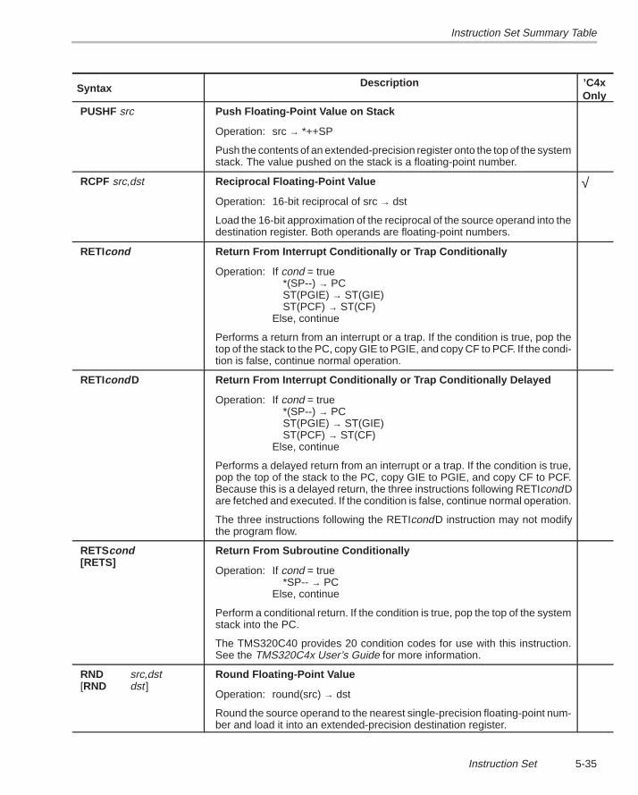
Instruction Set Summary Table
5-35Instruction Set
Syntax ’C4xOnly
Description
PUSHF src Push Floating-Point Value on Stack
Operation: src → *++SP
Push the contents of an extended-precision register onto the top of the systemstack. The value pushed on the stack is a floating-point number.
RCPF src,dst Reciprocal Floating-Point Value
Operation: 16-bit reciprocal of src → dst
Load the 16-bit approximation of the reciprocal of the source operand into thedestination register. Both operands are floating-point numbers.
√
RETIcond Return From Interrupt Conditionally or Trap Conditionally
Operation: If cond = true*(SP--) → PCST(PGIE) → ST(GIE)ST(PCF) → ST(CF)
Else, continue
Performs a return from an interrupt or a trap. If the condition is true, pop thetop of the stack to the PC, copy GIE to PGIE, and copy CF to PCF. If the condi-tion is false, continue normal operation.
RETIcond D Return From Interrupt Conditionally or Trap Conditionally Delayed
Operation: If cond = true*(SP--) → PCST(PGIE) → ST(GIE)ST(PCF) → ST(CF)
Else, continue
Performs a delayed return from an interrupt or a trap. If the condition is true,pop the top of the stack to the PC, copy GIE to PGIE, and copy CF to PCF.Because this is a delayed return, the three instructions following RETIcondDare fetched and executed. If the condition is false, continue normal operation.
The three instructions following the RETIcondD instruction may not modifythe program flow.
RETScond[RETS]
Return From Subroutine Conditionally
Operation: If cond = true*SP-- → PC
Else, continue
Perform a conditional return. If the condition is true, pop the top of the systemstack into the PC.
The TMS320C40 provides 20 condition codes for use with this instruction.See the TMS320C4x User’s Guide for more information.
RND src,dst[RND dst ]
Round Floating-Point Value
Operation: round(src) → dst
Round the source operand to the nearest single-precision floating-point num-ber and load it into an extended-precision destination register.
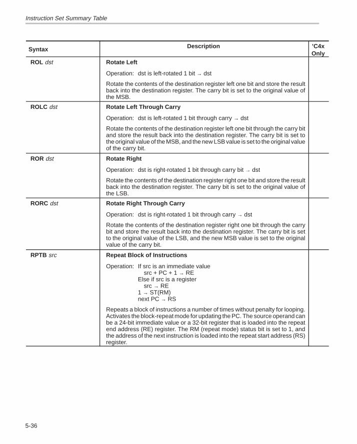
Instruction Set Summary Table
5-36
Syntax ’C4xOnly
Description
ROL dst Rotate Left
Operation: dst is left-rotated 1 bit → dst
Rotate the contents of the destination register left one bit and store the resultback into the destination register. The carry bit is set to the original value ofthe MSB.
ROLC dst Rotate Left Through Carry
Operation: dst is left-rotated 1 bit through carry → dst
Rotate the contents of the destination register left one bit through the carry bitand store the result back into the destination register. The carry bit is set tothe original value of the MSB, and the new LSB value is set to the original valueof the carry bit.
ROR dst Rotate Right
Operation: dst is right-rotated 1 bit through carry bit → dst
Rotate the contents of the destination register right one bit and store the resultback into the destination register. The carry bit is set to the original value ofthe LSB.
RORC dst Rotate Right Through Carry
Operation: dst is right-rotated 1 bit through carry → dst
Rotate the contents of the destination register right one bit through the carrybit and store the result back into the destination register. The carry bit is setto the original value of the LSB, and the new MSB value is set to the originalvalue of the carry bit.
RPTB src Repeat Block of Instructions
Operation: If src is an immediate valuesrc + PC + 1 → RE
Else if src is a registersrc → RE
1 → ST(RM)next PC → RS
Repeats a block of instructions a number of times without penalty for looping.Activates the block-repeat mode for updating the PC. The source operand canbe a 24-bit immediate value or a 32-bit register that is loaded into the repeatend address (RE) register. The RM (repeat mode) status bit is set to 1, andthe address of the next instruction is loaded into the repeat start address (RS)register.
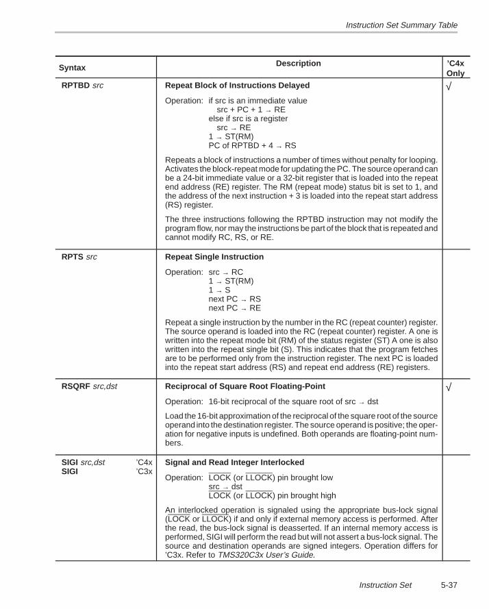
Instruction Set Summary Table
5-37Instruction Set
Syntax ’C4xOnly
Description
RPTBD src Repeat Block of Instructions Delayed
Operation: if src is an immediate valuesrc + PC + 1 → RE
else if src is a registersrc → RE
1 → ST(RM)PC of RPTBD + 4 → RS
Repeats a block of instructions a number of times without penalty for looping.Activates the block-repeat mode for updating the PC. The source operand canbe a 24-bit immediate value or a 32-bit register that is loaded into the repeatend address (RE) register. The RM (repeat mode) status bit is set to 1, andthe address of the next instruction + 3 is loaded into the repeat start address(RS) register.
The three instructions following the RPTBD instruction may not modify theprogram flow, nor may the instructions be part of the block that is repeated andcannot modify RC, RS, or RE.
√
RPTS src Repeat Single Instruction
Operation: src → RC1 → ST(RM)1 → Snext PC → RSnext PC → RE
Repeat a single instruction by the number in the RC (repeat counter) register.The source operand is loaded into the RC (repeat counter) register. A one iswritten into the repeat mode bit (RM) of the status register (ST) A one is alsowritten into the repeat single bit (S). This indicates that the program fetchesare to be performed only from the instruction register. The next PC is loadedinto the repeat start address (RS) and repeat end address (RE) registers.
RSQRF src,dst Reciprocal of Square Root Floating-Point
Operation: 16-bit reciprocal of the square root of src → dst
Load the 16-bit approximation of the reciprocal of the square root of the sourceoperand into the destination register. The source operand is positive; the oper-ation for negative inputs is undefined. Both operands are floating-point num-bers.
√
SIGI src,dst ’C4xSIGI ’C3x
Signal and Read Integer Interlocked
Operation: LOCK (or LLOCK) pin brought lowsrc → dstLOCK (or LLOCK) pin brought high
An interlocked operation is signaled using the appropriate bus-lock signal(LOCK or LLOCK) if and only if external memory access is performed. Afterthe read, the bus-lock signal is deasserted. If an internal memory access isperformed, SIGI will perform the read but will not assert a bus-lock signal. Thesource and destination operands are signed integers. Operation differs for’C3x. Refer to TMS320C3x User’s Guide.
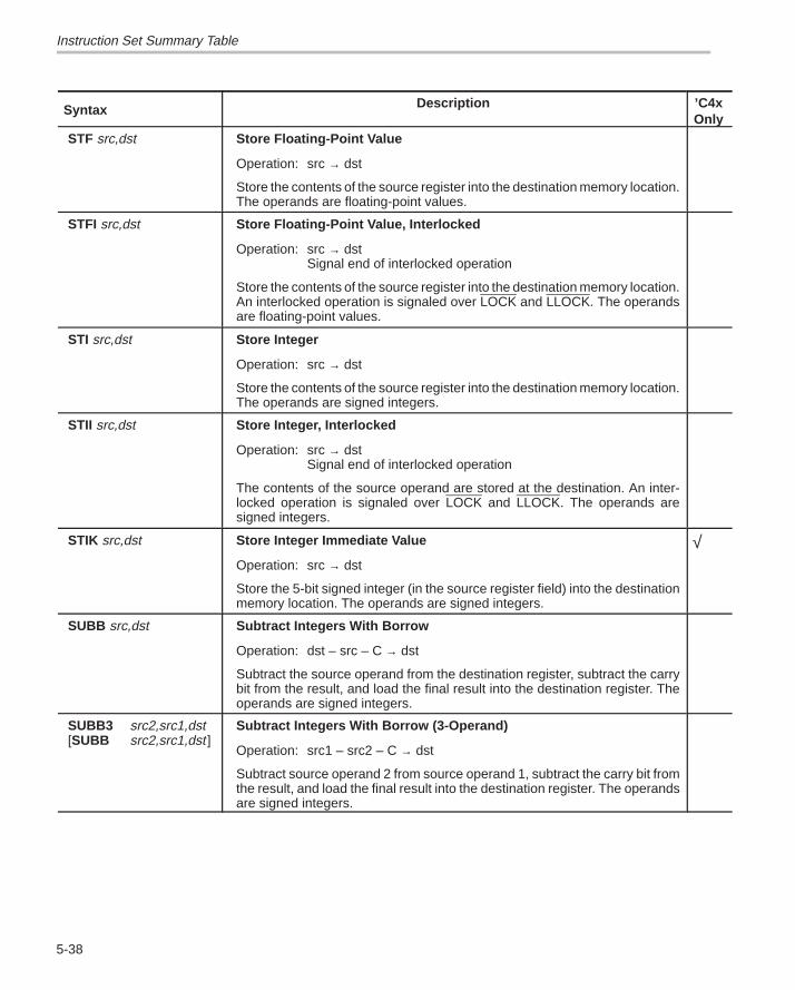
Instruction Set Summary Table
5-38
Syntax ’C4xOnly
Description
STF src,dst Store Floating-Point Value
Operation: src → dst
Store the contents of the source register into the destination memory location.The operands are floating-point values.
STFI src,dst Store Floating-Point Value, Interlocked
Operation: src → dstSignal end of interlocked operation
Store the contents of the source register into the destination memory location.An interlocked operation is signaled over LOCK and LLOCK. The operandsare floating-point values.
STI src,dst Store Integer
Operation: src → dst
Store the contents of the source register into the destination memory location.The operands are signed integers.
STII src,dst Store Integer, Interlocked
Operation: src → dstSignal end of interlocked operation
The contents of the source operand are stored at the destination. An inter-locked operation is signaled over LOCK and LLOCK. The operands aresigned integers.
STIK src,dst Store Integer Immediate Value
Operation: src → dst
Store the 5-bit signed integer (in the source register field) into the destinationmemory location. The operands are signed integers.
√
SUBB src,dst Subtract Integers With Borrow
Operation: dst – src – C → dst
Subtract the source operand from the destination register, subtract the carrybit from the result, and load the final result into the destination register. Theoperands are signed integers.
SUBB3 src2,src1,dst[SUBB src2,src1,dst ]
Subtract Integers With Borrow (3-Operand)
Operation: src1 – src2 – C → dst
Subtract source operand 2 from source operand 1, subtract the carry bit fromthe result, and load the final result into the destination register. The operandsare signed integers.
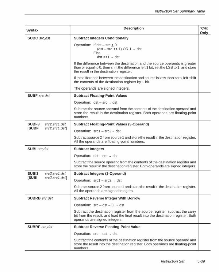
Instruction Set Summary Table
5-39Instruction Set
Syntax ’C4xOnly
Description
SUBC src,dst Subtract Integers Conditionally
Operation: If dst – src > 0(dst – src << 1) OR 1 → dst
Elsedst <<1 → dst
If the difference between the destination and the source operands is greaterthan or equal to 0, then shift the difference left 1 bit, set the LSB to 1, and storethe result in the destination register.
If the difference between the destination and source is less than zero, left-shiftthe contents of the destination register by 1 bit.
The operands are signed integers.
SUBF src,dst Subtract Floating-Point Values
Operation: dst – src → dst
Subtract the source operand from the contents of the destination operand andstore the result in the destination register. Both operands are floating-pointnumbers.
SUBF3 src2,src1,dst[SUBF src2,src1,dst ]
Subtract Floating-Point Values (3-Operand)
Operation: src1 – src2→ dst
Subtract source 2 from source 1 and store the result in the destination register.All the operands are floating-point numbers.
SUBI src,dst Subtract Integers
Operation: dst – src → dst
Subtract the source operand from the contents of the destination register andstore the result in the destination register. Both operands are signed integers.
SUBI3 src2,src1,dst[SUBI src2,src1,dst ]
Subtract Integers (3-Operand)
Operation: src1 – src2 → dst
Subtract source 2 from source 1 and store the result in the destination register.All the operands are signed integers.
SUBRB src,dst Subtract Reverse Integer With Borrow
Operation: src – dst – C → dst
Subtract the destination register from the source register, subtract the carrybit from the result, and load the final result into the destination register. Bothoperands are signed integers.
SUBRF src,dst Subtract Reverse Floating-Point Value
Operation: src – dst → dst
Subtract the contents of the destination register from the source operand andstore the result into the destination register. Both operands are floating-pointnumbers.
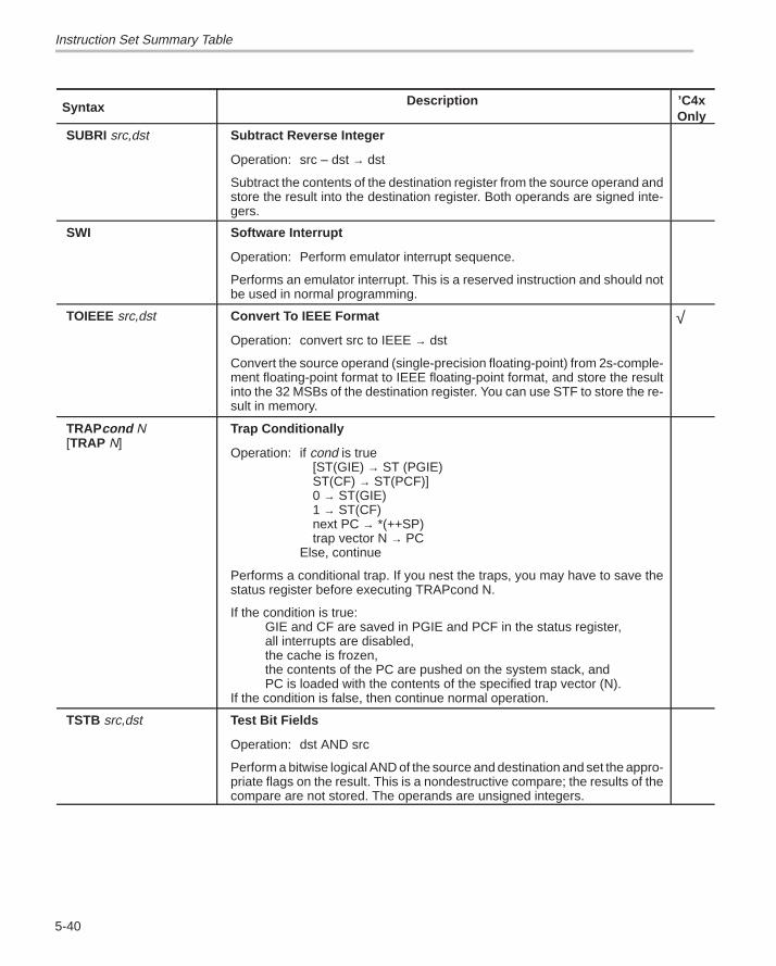
Instruction Set Summary Table
5-40
Syntax ’C4xOnly
Description
SUBRI src,dst Subtract Reverse Integer
Operation: src – dst → dst
Subtract the contents of the destination register from the source operand andstore the result into the destination register. Both operands are signed inte-gers.
SWI Software Interrupt
Operation: Perform emulator interrupt sequence.
Performs an emulator interrupt. This is a reserved instruction and should notbe used in normal programming.
TOIEEE src,dst Convert To IEEE Format
Operation: convert src to IEEE → dst
Convert the source operand (single-precision floating-point) from 2s-comple-ment floating-point format to IEEE floating-point format, and store the resultinto the 32 MSBs of the destination register. You can use STF to store the re-sult in memory.
√
TRAPcond N[TRAP N]
Trap Conditionally
Operation: if cond is true[ST(GIE) → ST (PGIE)ST(CF) → ST(PCF)]0 → ST(GIE)1 → ST(CF)next PC → *(++SP)trap vector N → PC
Else, continue
Performs a conditional trap. If you nest the traps, you may have to save thestatus register before executing TRAPcond N.
If the condition is true:GIE and CF are saved in PGIE and PCF in the status register,all interrupts are disabled, the cache is frozen, the contents of the PC are pushed on the system stack, andPC is loaded with the contents of the specified trap vector (N).
If the condition is false, then continue normal operation.
TSTB src,dst Test Bit Fields
Operation: dst AND src
Perform a bitwise logical AND of the source and destination and set the appro-priate flags on the result. This is a nondestructive compare; the results of thecompare are not stored. The operands are unsigned integers.
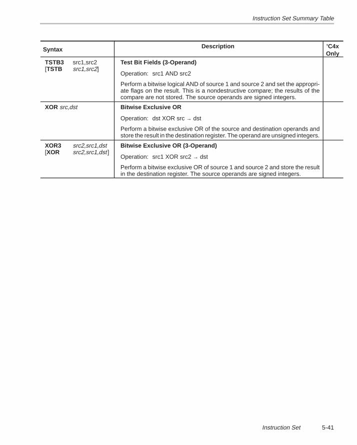
Instruction Set Summary Table
5-41Instruction Set
Syntax ’C4xOnly
Description
TSTB3 src1,src2[TSTB src1,src2]
Test Bit Fields (3-Operand)
Operation: src1 AND src2
Perform a bitwise logical AND of source 1 and source 2 and set the appropri-ate flags on the result. This is a nondestructive compare; the results of thecompare are not stored. The source operands are signed integers.
XOR src,dst Bitwise Exclusive OR
Operation: dst XOR src → dst
Perform a bitwise exclusive OR of the source and destination operands andstore the result in the destination register. The operand are unsigned integers.
XOR3 src2,src1,dst[XOR src2,src1,dst ]
Bitwise Exclusive OR (3-Operand)
Operation: src1 XOR src2 → dst
Perform a bitwise exclusive OR of source 1 and source 2 and store the resultin the destination register. The source operands are signed integers.
6-1Macro Language
Macro Language
The TMS320C3x/C4x assembler supports a macro language that enables youto create your own “instructions”. This is especially useful when a programexecutes a particular task several times. The macro language enables you todo the following:
� Define your own macros and redefine existing macros,
� Simplify long or complicated assembly code,
� Access macro libraries created with the archiver,
� Define conditional and repeatable blocks within a macro,
� Manipulate strings within a macro, and
� Control expansion listing.
This chapter discusses the following topics:
Topic Page
6.1 Using Macros 6-2. . . . . . . . . . . . . . . . . . . . . . . . . . . . . . . . . . . . . . . . . . . . . . . . .
6.2 Defining Macros 6-3. . . . . . . . . . . . . . . . . . . . . . . . . . . . . . . . . . . . . . . . . . . . . .
6.3 Macro Parameters/Substitution Symbols 6-5. . . . . . . . . . . . . . . . . . . . . . . .
6.4 Macro Libraries 6-13. . . . . . . . . . . . . . . . . . . . . . . . . . . . . . . . . . . . . . . . . . . . . .
6.5 Using Conditional Assembly in Macros 6-14. . . . . . . . . . . . . . . . . . . . . . . .
6.6 Using Labels in Macros 6-16. . . . . . . . . . . . . . . . . . . . . . . . . . . . . . . . . . . . . . .
6.7 Producing Messages in Macros 6-17. . . . . . . . . . . . . . . . . . . . . . . . . . . . . . .
6.8 Formatting the Output Listing 6-19. . . . . . . . . . . . . . . . . . . . . . . . . . . . . . . . .
6.9 Using Recursive and Nested Macros 6-20. . . . . . . . . . . . . . . . . . . . . . . . . .
6.10 Macro Directives Summary 6-22. . . . . . . . . . . . . . . . . . . . . . . . . . . . . . . . . . .
Chapter 6
Using Macros
6-2
6.1 Using Macros
Programs often contain routines that are executed several times. Instead ofrepeating the source statements for a routine, you can define the routine asa macro, then call the macro in the places where you would normally repeatthe routine. This simplifies and shortens your source program.
If you want to call a macro several times, but with different data each time, youcan assign parameters to a macro. This enables you to pass different informa-tion to the macro each time you call it. The macro language supports a specialsymbol called a substitution symbol , which is used for macro parameters.In this chapter, we use the terms macro parameters and substitution symbolsinterchangeably.
Using a macro is a three-step process.
Step 1: Define the macro. You must define macros before you can use themin your program. There are two methods for defining macros:
� Macros can be defined at the beginning of a source file or in an.include/.copy file. Refer to Section 6.2 for more information.
� Macros can also be defined in a macro library. A macro libraryis a collection of files in archive format, created by the archiver.Each member of the archive file (macro library) may contain onemacro definition corresponding to the member name. You canaccess a macro library by using the .mlib directive. Macro li-braries are discussed in Section 6.4 on page 6-13.
Step 2: Call the macro. After you have defined a macro, you can call it byusing the macro name as an opcode in the source program. This isreferred to as a macro call.
Step 3: Expand the macro. The assembler expands your macros when thesource program calls them. During expansion, the assemblerpasses arguments by variable to the macro parameters, replacesthe macro call statement with the macro definition, then assemblesthe source code. By default, the macro expansions are printed in thelisting file. You can turn off expansion listing by using the .mnolistdirective. For more information, refer to Section 6.8 on page 6-19.
When the assembler encounters a macro definition, it places the macro namein the opcode table. This redefines any previously defined macro, library entry,directive, or instruction mnemonic that has the same name as the encounteredmacro. This allows you to expand the functions of directives and instructions,as well as add new instructions.
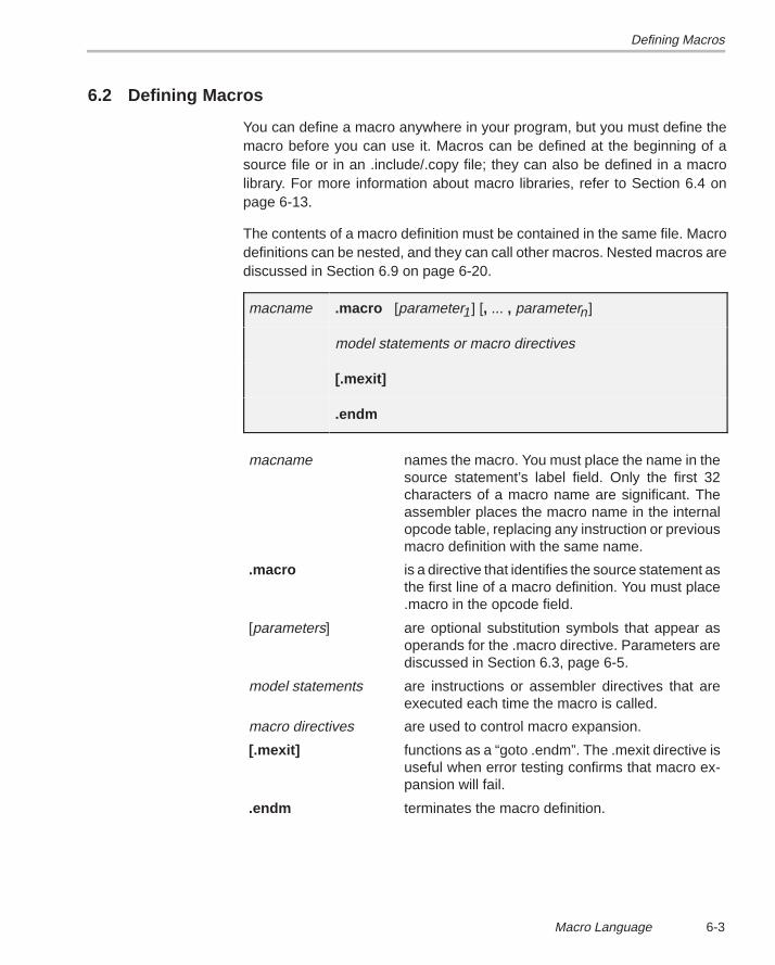
Defining Macros
6-3Macro Language
6.2 Defining Macros
You can define a macro anywhere in your program, but you must define themacro before you can use it. Macros can be defined at the beginning of asource file or in an .include/.copy file; they can also be defined in a macrolibrary. For more information about macro libraries, refer to Section 6.4 onpage 6-13.
The contents of a macro definition must be contained in the same file. Macrodefinitions can be nested, and they can call other macros. Nested macros arediscussed in Section 6.9 on page 6-20.
macname .macro [parameter1] [, ... , parametern]
model statements or macro directives
[.mexit]
.endm
macname names the macro. You must place the name in thesource statement’s label field. Only the first 32characters of a macro name are significant. Theassembler places the macro name in the internalopcode table, replacing any instruction or previousmacro definition with the same name.
.macro is a directive that identifies the source statement asthe first line of a macro definition. You must place.macro in the opcode field.
[parameters] are optional substitution symbols that appear asoperands for the .macro directive. Parameters arediscussed in Section 6.3, page 6-5.
model statements are instructions or assembler directives that areexecuted each time the macro is called.
macro directives are used to control macro expansion.
[.mexit] functions as a “goto .endm”. The .mexit directive isuseful when error testing confirms that macro ex-pansion will fail.
.endm terminates the macro definition.
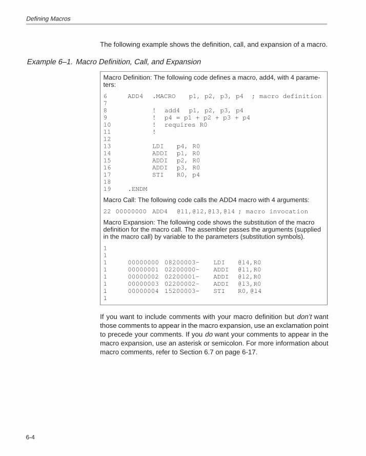
Defining Macros
6-4
The following example shows the definition, call, and expansion of a macro.
Example 6–1. Macro Definition, Call, and Expansion
Macro Definition: The following code defines a macro, add4, with 4 parame-ters:
6 ADD4 .MACRO p1, p2, p3, p4 ; macro definition78 ! add4 p1, p2, p3, p49 ! p4 = p1 + p2 + p3 + p410 ! requires R011 !1213 LDI p4, R014 ADDI p1, R0 15 ADDI p2, R016 ADDI p3, R017 STI R0, p41819 .ENDM
Macro Call: The following code calls the ADD4 macro with 4 arguments:
22 00000000 ADD4 @l1,@l2,@l3,@l4 ; macro invocation
Macro Expansion: The following code shows the substitution of the macrodefinition for the macro call. The assembler passes the arguments (suppliedin the macro call) by variable to the parameters (substitution symbols).
111 00000000 08200003– LDI @l4,R01 00000001 02200000– ADDI @l1,R01 00000002 02200001– ADDI @l2,R01 00000003 02200002– ADDI @l3,R01 00000004 15200003– STI R0,@l41
If you want to include comments with your macro definition but don’t wantthose comments to appear in the macro expansion, use an exclamation pointto precede your comments. If you do want your comments to appear in themacro expansion, use an asterisk or semicolon. For more information aboutmacro comments, refer to Section 6.7 on page 6-17.
Macro Parameters/Substitution Symbols
6-5Macro Language
6.3 Macro Parameters/Substitution Symbols
If you want to call a macro several times, but with different data each time, youcan assign parameters to the macro. The macro language supports a specialsymbol, called a substitution symbol , which is used for macro parameters.
6.3.1 Substitution Symbols
Macro parameters are substitution symbols. Substitution symbols are sym-bols that represent a character string. Besides being used as macroparameters, these symbols can also be manipulated by .asg or .eval, outsideof macros, to equate a character string to a symbol name.
Valid substitution symbols may be 32 characters long and must begin with aletter. The remainder of the symbol can be a combination of alphanumericcharacters, underscores, and dollar signs.
Substitution symbols used as macro parameters are local to the macro theyare defined in. You can define up to 32 local substitution symbols (includingsubstitution symbols defined with the .var directive) per macro. For moreinformation about the .var directive, refer to page 6-12.
During macro expansion, the assembler passes arguments by variable to themacro parameters. The character-string equivalent of each argument isassigned to the corresponding parameter. Parameters without correspondingarguments are set to the null string. If the number of arguments exceeds thenumber of parameters, the last parameter is assigned the character-stringequivalent of all remaining arguments.
If you pass a list of arguments to one parameter, or if you pass a comma orsemicolon to a parameter, you must surround the arguments with quotationmarks.
At assembly time, the assembler first replaces the substitution symbol with itscorresponding character string, then translates the source code into objectcode.
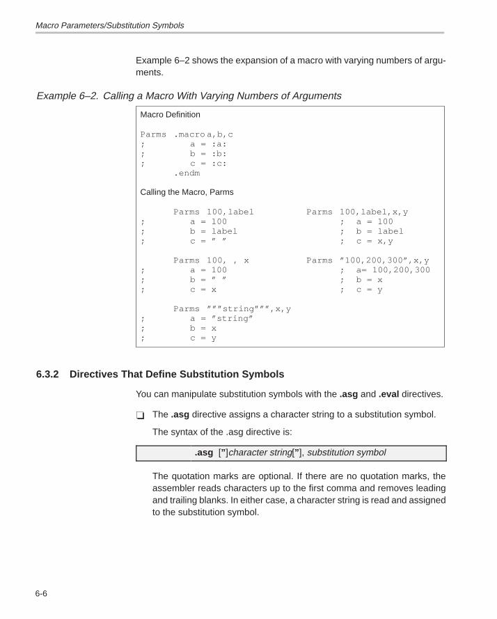
Macro Parameters/Substitution Symbols
6-6
Example 6–2 shows the expansion of a macro with varying numbers of argu-ments.
Example 6–2. Calling a Macro With Varying Numbers of Arguments
Macro Definition
Parms .macro a,b,c; a = :a:; b = :b:; c = :c:
.endm
Calling the Macro, Parms
Parms 100,label Parms 100,label,x,y; a = 100 ; a = 100; b = label ; b = label; c = ” ” ; c = x,y
Parms 100, , x Parms ”100,200,300”,x,y; a = 100 ; a= 100,200,300; b = ” ” ; b = x; c = x ; c = y
Parms ”””string”””,x,y; a = ”string”; b = x; c = y
6.3.2 Directives That Define Substitution Symbols
You can manipulate substitution symbols with the .asg and .eval directives.
� The .asg directive assigns a character string to a substitution symbol.
The syntax of the .asg directive is:
.asg [” ]character string[” ], substitution symbol
The quotation marks are optional. If there are no quotation marks, theassembler reads characters up to the first comma and removes leadingand trailing blanks. In either case, a character string is read and assignedto the substitution symbol.
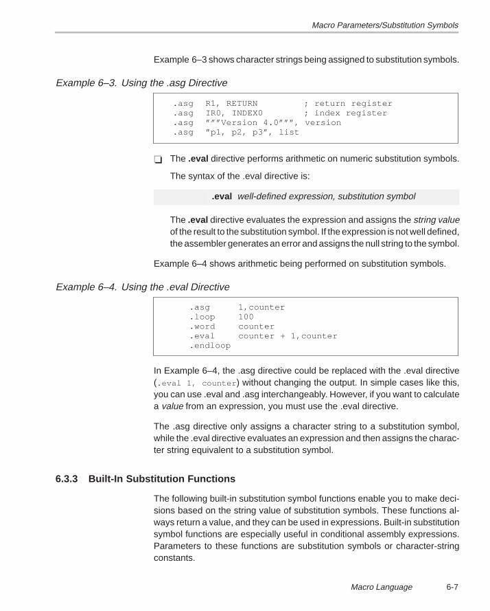
Macro Parameters/Substitution Symbols
6-7Macro Language
Example 6–3 shows character strings being assigned to substitution symbols.
Example 6–3. Using the .asg Directive
.asg R1, RETURN ; return register
.asg IR0, INDEX0 ; index register
.asg ”””Version 4.0”””, version
.asg ”p1, p2, p3”, list
� The .eval directive performs arithmetic on numeric substitution symbols.
The syntax of the .eval directive is:
.eval well-defined expression, substitution symbol
The .eval directive evaluates the expression and assigns the string valueof the result to the substitution symbol. If the expression is not well defined,the assembler generates an error and assigns the null string to the symbol.
Example 6–4 shows arithmetic being performed on substitution symbols.
Example 6–4. Using the .eval Directive
.asg 1,counter
.loop 100
.word counter
.eval counter + 1,counter
.endloop
In Example 6–4, the .asg directive could be replaced with the .eval directive(.eval 1, counter ) without changing the output. In simple cases like this,you can use .eval and .asg interchangeably. However, if you want to calculatea value from an expression, you must use the .eval directive.
The .asg directive only assigns a character string to a substitution symbol,while the .eval directive evaluates an expression and then assigns the charac-ter string equivalent to a substitution symbol.
6.3.3 Built-In Substitution Functions
The following built-in substitution symbol functions enable you to make deci-sions based on the string value of substitution symbols. These functions al-ways return a value, and they can be used in expressions. Built-in substitutionsymbol functions are especially useful in conditional assembly expressions.Parameters to these functions are substitution symbols or character-stringconstants.
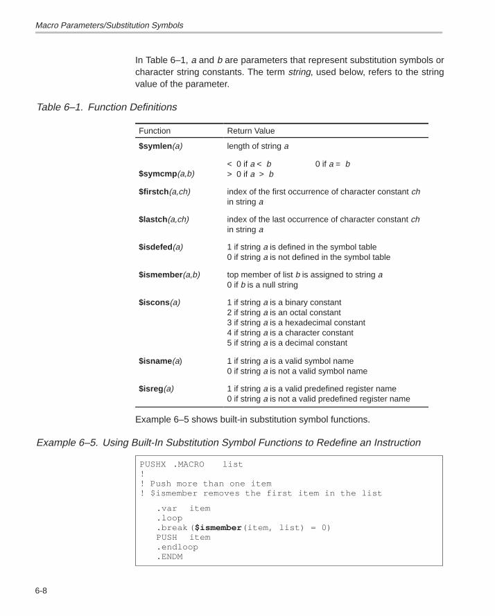
Macro Parameters/Substitution Symbols
6-8
In Table 6–1, a and b are parameters that represent substitution symbols orcharacter string constants. The term string, used below, refers to the stringvalue of the parameter.
Table 6–1. Function Definitions
Function Return Value
$symlen (a) length of string a
$symcmp (a,b)< 0 if a < b 0 if a = b> 0 if a > b
$firstch (a,ch) index of the first occurrence of character constant chin string a
$lastch (a,ch) index of the last occurrence of character constant chin string a
$isdefed (a) 1 if string a is defined in the symbol table0 if string a is not defined in the symbol table
$ismember (a,b) top member of list b is assigned to string a0 if b is a null string
$iscons (a) 1 if string a is a binary constant2 if string a is an octal constant3 if string a is a hexadecimal constant4 if string a is a character constant5 if string a is a decimal constant
$isname (a) 1 if string a is a valid symbol name0 if string a is not a valid symbol name
$isreg (a) 1 if string a is a valid predefined register name0 if string a is not a valid predefined register name
Example 6–5 shows built-in substitution symbol functions.
Example 6–5. Using Built-In Substitution Symbol Functions to Redefine an Instruction
PUSHX .MACRO list!! Push more than one item! $ismember removes the first item in the list
.var item
.loop
.break ( $ismember (item, list) = 0)PUSH item.endloop.ENDM
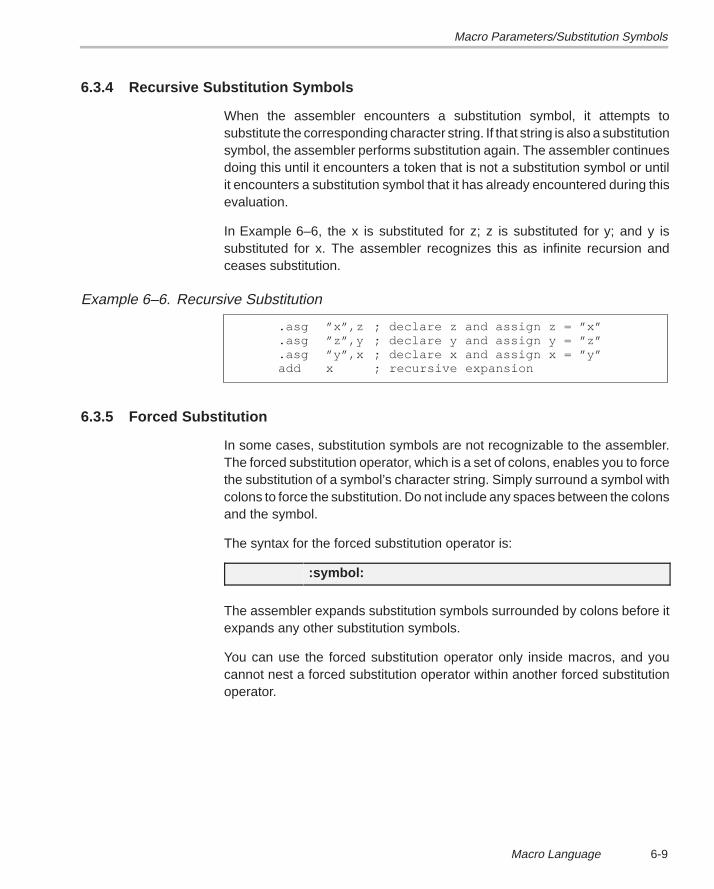
Macro Parameters/Substitution Symbols
6-9Macro Language
6.3.4 Recursive Substitution Symbols
When the assembler encounters a substitution symbol, it attempts tosubstitute the corresponding character string. If that string is also a substitutionsymbol, the assembler performs substitution again. The assembler continuesdoing this until it encounters a token that is not a substitution symbol or untilit encounters a substitution symbol that it has already encountered during thisevaluation.
In Example 6–6, the x is substituted for z; z is substituted for y; and y issubstituted for x. The assembler recognizes this as infinite recursion andceases substitution.
Example 6–6. Recursive Substitution
.asg ”x”,z ; declare z and assign z = ”x”
.asg ”z”,y ; declare y and assign y = ”z”
.asg ”y”,x ; declare x and assign x = ”y”add x ; recursive expansion
6.3.5 Forced Substitution
In some cases, substitution symbols are not recognizable to the assembler.The forced substitution operator, which is a set of colons, enables you to forcethe substitution of a symbol’s character string. Simply surround a symbol withcolons to force the substitution. Do not include any spaces between the colonsand the symbol.
The syntax for the forced substitution operator is:
:symbol:
The assembler expands substitution symbols surrounded by colons before itexpands any other substitution symbols.
You can use the forced substitution operator only inside macros, and youcannot nest a forced substitution operator within another forced substitutionoperator.
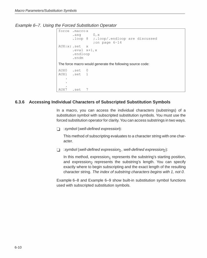
Macro Parameters/Substitution Symbols
6-10
Example 6–7. Using the Forced Substitution Operatorforce .macro x
.asg 0,x
.loop 8 ;.loop/.endloop are discussed;on page 6-14
AUX:x: .set x.eval x+1,x.endloop.endm
The force macro would generate the following source code:
AUX0 .set 0AUX1 .set 1
.
.
.AUX7 .set 7
6.3.6 Accessing Individual Characters of Subscripted Substitution Symbols
In a macro, you can access the individual characters (substrings) of asubstitution symbol with subscripted substitution symbols. You must use theforced substitution operator for clarity. You can access substrings in two ways.
� :symbol (well-defined expression):
This method of subscripting evaluates to a character string with one char-acter.
� :symbol (well-defined expression1, well-defined expression2):
In this method, expression1 represents the substring’s starting position,and expression2 represents the substring’s length. You can specifyexactly where to begin subscripting and the exact length of the resultingcharacter string. The index of substring characters begins with 1, not 0.
Example 6–8 and Example 6–9 show built-in substitution symbol functionsused with subscripted substitution symbols.
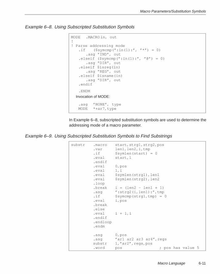
Macro Parameters/Substitution Symbols
6-11Macro Language
Example 6–8. Using Subscripted Substitution Symbols
MODE .MACRO in, out!! Parse addressing mode
.if ($symcmp(”:in(1):”, ”*”) = 0).asg ”IND”, out
.elseif ($symcmp(”:in(1):”, ”@”) = 0) .asg ”DIR”, out
.elseif $isreg(in).asg ”REG”, out
.elseif $isname(in).asg ”DIR”, out
.endif
.ENDM
Invocation of MODE:
.asg ”NONE”, typeMODE *+ar7,type
In Example 6–8, subscripted substitution symbols are used to determine theaddressing mode of a macro parameter.
Example 6–9. Using Subscripted Substitution Symbols to Find Substrings
substr .macro start,strg1,strg2,pos.var len1,len2,i,tmp.if $symlen(start) = 0.eval start,1.endif.eval 0,pos.eval 1,i.eval $symlen(strg1),len1.eval $symlen(strg2),len2.loop.break i = (len2 – len1 + 1).asg ”:strg2(i,len1):”,tmp.if $symcmp(strg1,tmp) = 0.eval i,pos.break.else.eval i + 1,i.endif.endloop.endm
.asg 0,pos
.asg ”ar1 ar2 ar3 ar4”,regssubstr 1,”ar2”,regs,pos.word pos ; pos has value 5
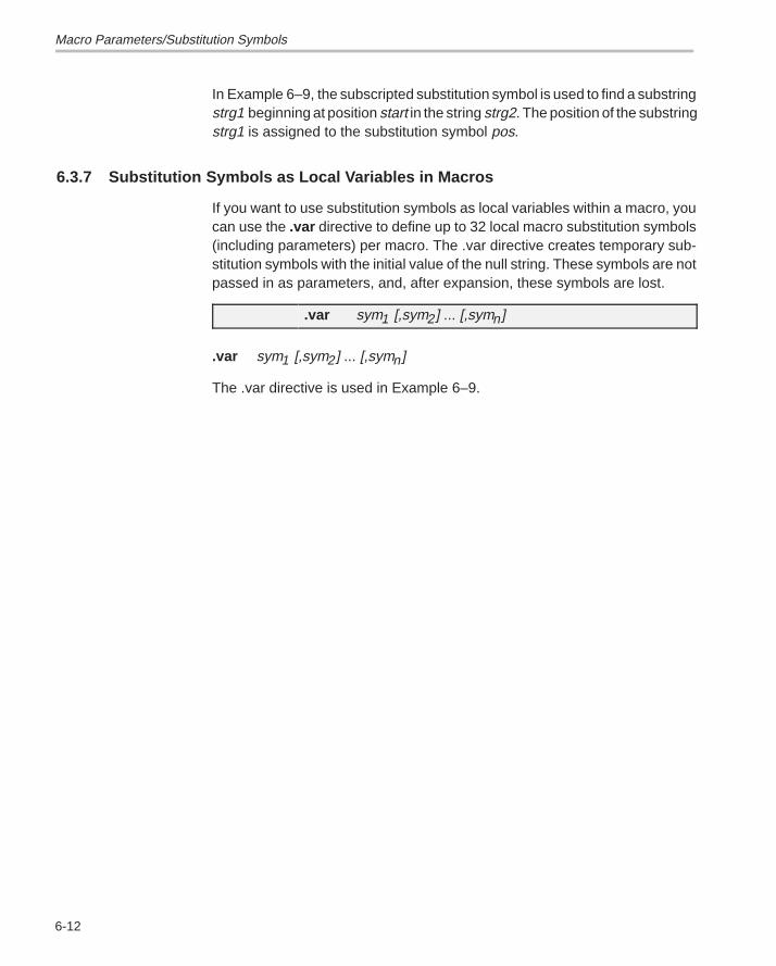
Macro Parameters/Substitution Symbols
6-12
In Example 6–9, the subscripted substitution symbol is used to find a substringstrg1 beginning at position start in the string strg2. The position of the substringstrg1 is assigned to the substitution symbol pos.
6.3.7 Substitution Symbols as Local Variables in Macros
If you want to use substitution symbols as local variables within a macro, youcan use the .var directive to define up to 32 local macro substitution symbols(including parameters) per macro. The .var directive creates temporary sub-stitution symbols with the initial value of the null string. These symbols are notpassed in as parameters, and, after expansion, these symbols are lost.
.var sym1 [,sym2] ... [,symn]
.var sym1 [,sym2] ... [,symn]
The .var directive is used in Example 6–9.
Macro Libraries
6-13Macro Language
6.4 Macro Libraries
One of the ways you can define macros is in a macro library. A macro libraryis a collection of files that contain macro definitions. You must use the archiverto collect these files, or members, into a single file (called an archive). Eachmember of a macro library contains one macro definition. The files in a macrolibrary must be unassembled source files. The macro name and the membername must be the same, and the macro filename’s extension must be .asm.For example,
Macro Name Filename in Macro Library
simple simple.asm
mode mode.asm
You can access the macro library by using the .mlib assembler directive.
.mlib macro library filename
When the assembler encounters an .mlib directive, it opens the library andcreates a table of its contents. The assembler enters the names of theindividual members within the library into the opcode tables as library entries;this redefines any existing opcodes or macros that have the same name. If oneof these macros is called, the assembler extracts the entry from the library andloads it into the macro table. The assembler expands the library entry in thesame manner as other macros. You can control the listing of library entry ex-pansions with the .mlist directive. For more information about the .mlistdirective, refer to Section 6.8 on page 6-19. Only macros that are actuallycalled from the library are extracted, and they are extracted only once. Formore information about the .mlib directive, refer to page 4-53.
You can create a macro library with the archiver by simply including the desiredfiles in an archive. A macro library is no different from any other archive, exceptthat the assembler expects the macro library to contain macro definitions. Theassembler expects only macro definitions in a macro library; putting objectcode or miscellaneous source files into the library may produce undesirableeffects.
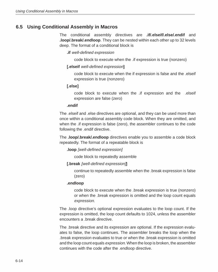
Using Conditional Assembly in Macros
6-14
6.5 Using Conditional Assembly in Macros
The conditional assembly directives are .if/.elseif/.else/.endif and.loop/.break/.endloop . They can be nested within each other up to 32 levelsdeep. The format of a conditional block is
.if well-defined expression
code block to execute when the .if expression is true (nonzero)
[.elseif well-defined expression]
code block to execute when the if expression is false and the .elseifexpression is true (nonzero)
[.else]
code block to execute when the .if expression and the .elseifexpression are false (zero)
.endif
The .elseif and .else directives are optional, and they can be used more thanonce within a conditional assembly code block. When they are omitted, andwhen the .if expression is false (zero), the assembler continues to the codefollowing the .endif directive.
The .loop/.break/.endloop directives enable you to assemble a code blockrepeatedly. The format of a repeatable block is
.loop [well-defined expression]
code block to repeatedly assemble
[.break [well-defined expression]]
continue to repeatedly assemble when the .break expression is false(zero)
.endloop
code block to execute when the .break expression is true (nonzero)or when the .break expression is omitted and the loop count equalsexpression.
The .loop directive’s optional expression evaluates to the loop count. If theexpression is omitted, the loop count defaults to 1024, unless the assemblerencounters a .break directive.
The .break directive and its expression are optional. If the expression evalu-ates to false, the loop continues. The assembler breaks the loop when the.break expression evaluates to true or when the .break expression is omittedand the loop count equals expression. When the loop is broken, the assemblercontinues with the code after the .endloop directive.
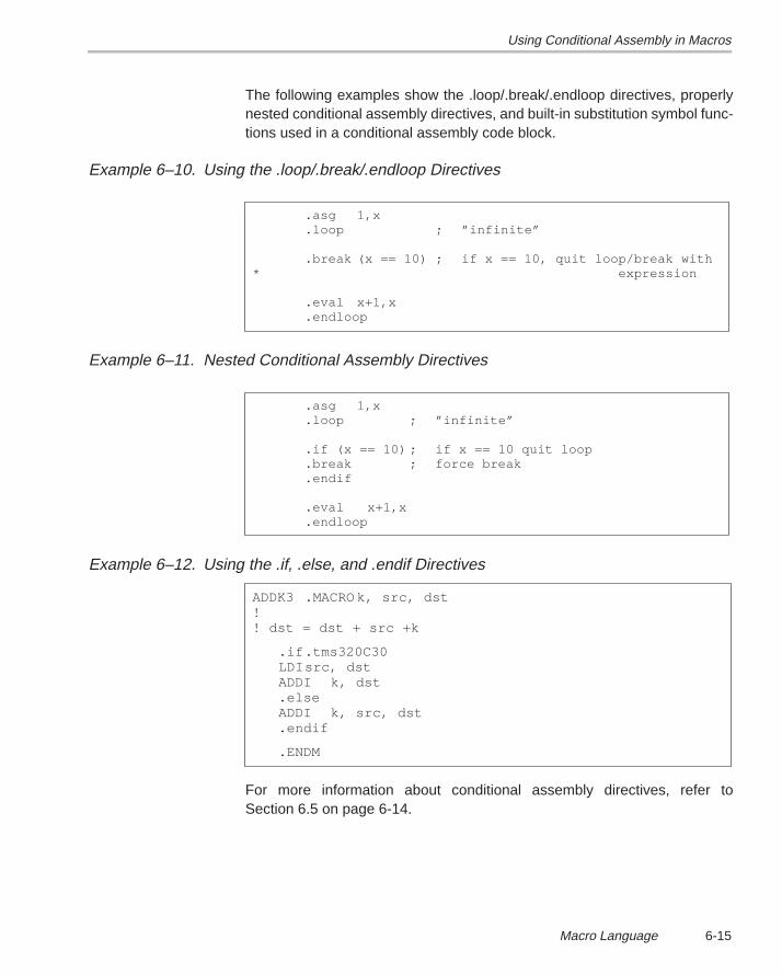
Using Conditional Assembly in Macros
6-15Macro Language
The following examples show the .loop/.break/.endloop directives, properlynested conditional assembly directives, and built-in substitution symbol func-tions used in a conditional assembly code block.
Example 6–10. Using the .loop/.break/.endloop Directives
.asg 1,x
.loop ; ”infinite”
.break (x == 10) ; if x == 10, quit loop/break with* expression
.eval x+1,x
.endloop
Example 6–11. Nested Conditional Assembly Directives
.asg 1,x
.loop ; ”infinite”
.if (x == 10) ; if x == 10 quit loop
.break ; force break
.endif
.eval x+1,x
.endloop
Example 6–12. Using the .if, .else, and .endif Directives
ADDK3 .MACRO k, src, dst!! dst = dst + src +k
.if .tms320C30LDIsrc, dstADDI k, dst.elseADDI k, src, dst.endif
.ENDM
For more information about conditional assembly directives, refer toSection 6.5 on page 6-14.
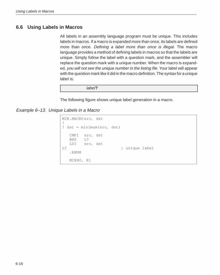
Using Labels in Macros
6-16
6.6 Using Labels in Macros
All labels in an assembly language program must be unique. This includeslabels in macros. If a macro is expanded more than once, its labels are definedmore than once. Defining a label more than once is illegal. The macrolanguage provides a method of defining labels in macros so that the labels areunique. Simply follow the label with a question mark, and the assembler willreplace the question mark with a unique number. When the macro is expand-ed, you will not see the unique number in the listing file. Your label will appearwith the question mark like it did in the macro definition. The syntax for a uniquelabel is:
label?
The following figure shows unique label generation in a macro.
Example 6–13. Unique Labels in a Macro
MIN.MACRO src, dst!! dst = minimum(src, dst)
CMPI src, dstBHS L?LDI src, dst
L? ; unique label.ENDM
MINR0, R1
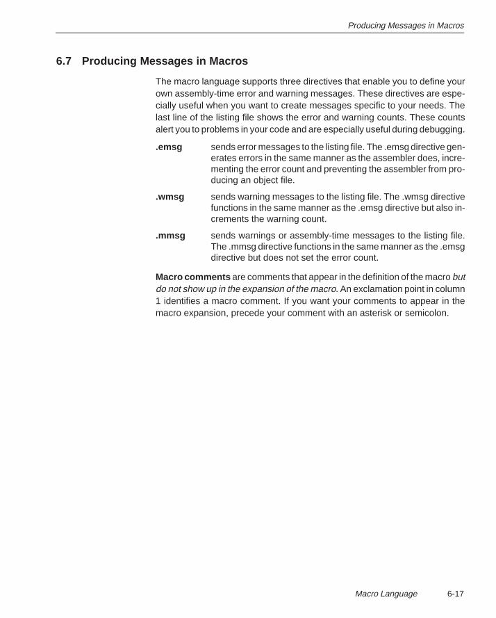
Producing Messages in Macros
6-17Macro Language
6.7 Producing Messages in Macros
The macro language supports three directives that enable you to define yourown assembly-time error and warning messages. These directives are espe-cially useful when you want to create messages specific to your needs. Thelast line of the listing file shows the error and warning counts. These countsalert you to problems in your code and are especially useful during debugging.
.emsg sends error messages to the listing file. The .emsg directive gen-erates errors in the same manner as the assembler does, incre-menting the error count and preventing the assembler from pro-ducing an object file.
.wmsg sends warning messages to the listing file. The .wmsg directivefunctions in the same manner as the .emsg directive but also in-crements the warning count.
.mmsg sends warnings or assembly-time messages to the listing file.The .mmsg directive functions in the same manner as the .emsgdirective but does not set the error count.
Macro comments are comments that appear in the definition of the macro butdo not show up in the expansion of the macro. An exclamation point in column1 identifies a macro comment. If you want your comments to appear in themacro expansion, precede your comment with an asterisk or semicolon.
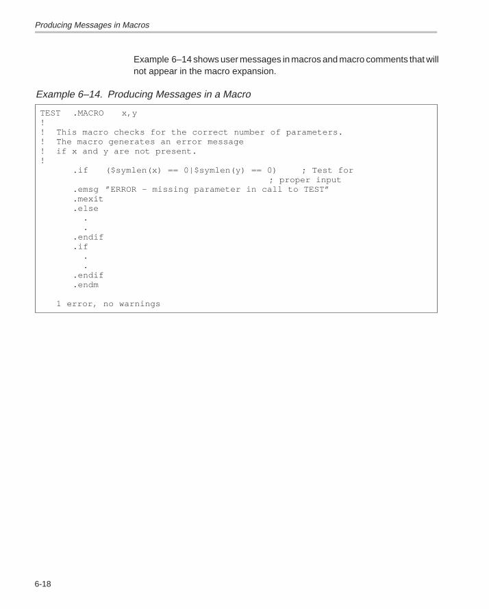
Producing Messages in Macros
6-18
Example 6–14 shows user messages in macros and macro comments that willnot appear in the macro expansion.
Example 6–14. Producing Messages in a Macro
TEST .MACRO x,y!! This macro checks for the correct number of parameters.! The macro generates an error message ! if x and y are not present.!
.if ($symlen(x) == 0|$symlen(y) == 0) ; Test for ; proper input
.emsg ”ERROR – missing parameter in call to TEST”
.mexit
.else . ..endif.if . ..endif.endm
1 error, no warnings
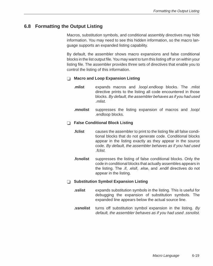
Formatting the Output Listing
6-19Macro Language
6.8 Formatting the Output Listing
Macros, substitution symbols, and conditional assembly directives may hideinformation. You may need to see this hidden information, so the macro lan-guage supports an expanded listing capability.
By default, the assembler shows macro expansions and false conditionalblocks in the list output file. You may want to turn this listing off or on within yourlisting file. The assembler provides three sets of directives that enable you tocontrol the listing of this information.
� Macro and Loop Expansion Listing
.mlist expands macros and .loop/.endloop blocks. The .mlistdirective prints to the listing all code encountered in thoseblocks. By default, the assembler behaves as if you had used.mlist.
.mnolist suppresses the listing expansion of macros and .loop/.endloop blocks.
� False Conditional Block Listing
.fclist causes the assembler to print to the listing file all false condi-tional blocks that do not generate code. Conditional blocksappear in the listing exactly as they appear in the sourcecode. By default, the assembler behaves as if you had used.fclist.
.fcnolist suppresses the listing of false conditional blocks. Only thecode in conditional blocks that actually assembles appears inthe listing. The .if, .elsif, .else, and .endif directives do notappear in the listing.
� Substitution Symbol Expansion Listing
.sslist expands substitution symbols in the listing. This is useful fordebugging the expansion of substitution symbols. Theexpanded line appears below the actual source line.
.ssnolist turns off substitution symbol expansion in the listing. Bydefault, the assembler behaves as if you had used .ssnolist.
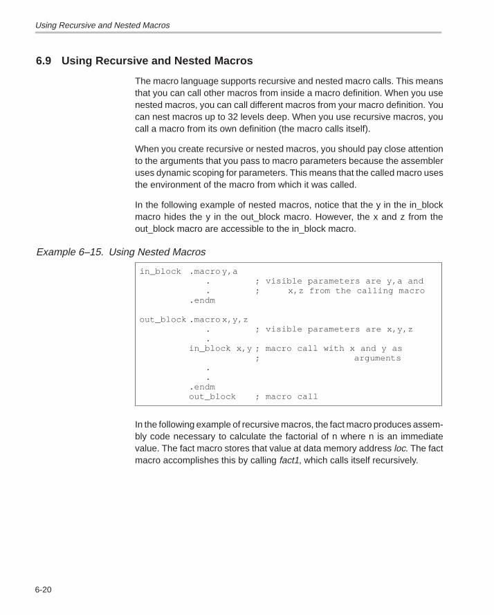
Using Recursive and Nested Macros
6-20
6.9 Using Recursive and Nested Macros
The macro language supports recursive and nested macro calls. This meansthat you can call other macros from inside a macro definition. When you usenested macros, you can call different macros from your macro definition. Youcan nest macros up to 32 levels deep. When you use recursive macros, youcall a macro from its own definition (the macro calls itself).
When you create recursive or nested macros, you should pay close attentionto the arguments that you pass to macro parameters because the assembleruses dynamic scoping for parameters. This means that the called macro usesthe environment of the macro from which it was called.
In the following example of nested macros, notice that the y in the in_blockmacro hides the y in the out_block macro. However, the x and z from theout_block macro are accessible to the in_block macro.
Example 6–15. Using Nested Macros
in_block .macro y,a. ; visible parameters are y,a and. ; x,z from the calling macro
.endm
out_block .macro x,y,z. ; visible parameters are x,y,z.
in_block x,y ; macro call with x and y as ; arguments
.
..endmout_block ; macro call
In the following example of recursive macros, the fact macro produces assem-bly code necessary to calculate the factorial of n where n is an immediatevalue. The fact macro stores that value at data memory address loc. The factmacro accomplishes this by calling fact1, which calls itself recursively.
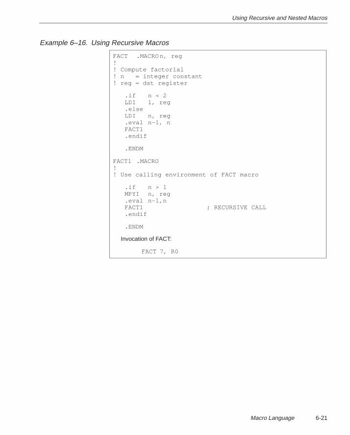
Using Recursive and Nested Macros
6-21Macro Language
Example 6–16. Using Recursive Macros
FACT .MACRO n, reg!! Compute factorial! n = integer constant! reg = dst register
.if n < 2LDI 1, reg.elseLDI n, reg.eval n–1, nFACT1.endif
.ENDM
FACT1 .MACRO!! Use calling environment of FACT macro
.if n > 1MPYI n, reg.eval n–1,nFACT1 ; RECURSIVE CALL.endif
.ENDM
Invocation of FACT:
FACT 7, R0
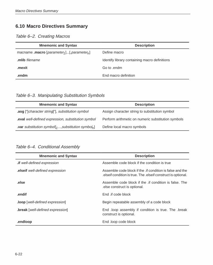
Macro Directives Summary
6-22
6.10 Macro Directives Summary
Table 6–2. Creating Macros
Mnemonic and Syntax Description
macname .macro [parameter1]...[,parametern] Define macro
.mlib filename Identify library containing macro definitions
.mexit Go to .endm
.endm End macro definition
Table 6–3. Manipulating Substitution Symbols
Mnemonic and Syntax Description
.asg [“]character string[”], substitution symbol Assign character string to substitution symbol
.eval well-defined expression, substitution symbol Perform arithmetic on numeric substitution symbols
.var substitution symbol [1...,substitution symboln] Define local macro symbols
Table 6–4. Conditional Assembly
Mnemonic and Syntax Description
.if well-defined expression Assemble code block if the condition is true
.elseif well-defined expression Assemble code block if the .if condition is false and the.elseif condition is true. The .elseif construct is optional.
.else Assemble code block if the .if condition is false. The.else construct is optional.
.endif End .if code block
.loop [well-defined expression] Begin repeatable assembly of a code block
.break [well-defined expression] End .loop assembly if condition is true. The .breakconstruct is optional.
.endloop End .loop code block
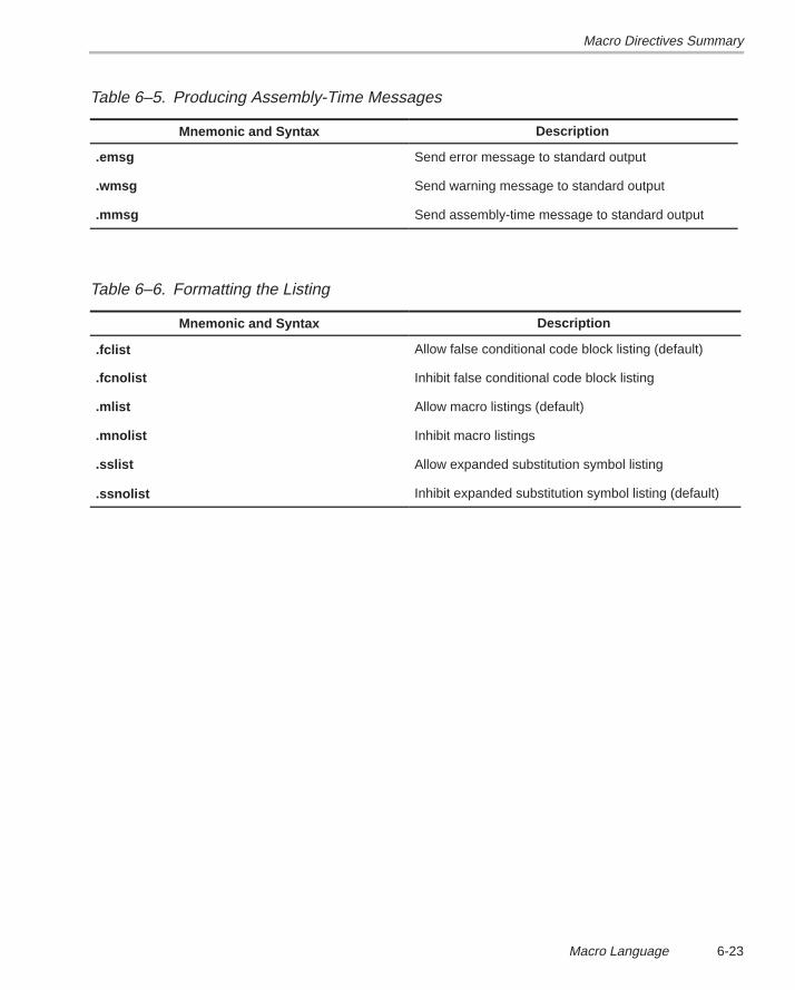
Macro Directives Summary
6-23Macro Language
Table 6–5. Producing Assembly-Time Messages
Mnemonic and Syntax Description
.emsg Send error message to standard output
.wmsg Send warning message to standard output
.mmsg Send assembly-time message to standard output
Table 6–6. Formatting the Listing
Mnemonic and Syntax Description
.fclist Allow false conditional code block listing (default)
.fcnolist Inhibit false conditional code block listing
.mlist Allow macro listings (default)
.mnolist Inhibit macro listings
.sslist Allow expanded substitution symbol listing
.ssnolist Inhibit expanded substitution symbol listing (default)
7-1Archiver Description
Archiver Description
The TMS320C3x/C4x archiver lets you combine several individual files into asingle file called an archive or a library . Each file within the archive is calleda member. Once you have created an archive, you can use the archiver to addmore files to the library, delete or replace existing members, or extract mem-bers.
You can build libraries out of any type of files. Both the assembler and the linkeraccept archive libraries as input; the assembler can use libraries that containindividual source files, and the linker can use libraries that contain individualobject files.
One of the most useful applications of the archiver is to build a library of objectmodules. For example, you could write several arithmetic routines, assemblethem, and then use the archiver to collect the object files into a single, logicalgroup. You can then specify an object library as linker input. The linker willsearch through the library and include any members that resolve external ref-erences.
You can also use the archiver to build macro libraries. You can create severalseparate source files, each of which contains a single macro, and then use thearchiver to collect these macros into a single, functional group. The .mlibassembler directive lets you specify the name of a macro library to theassembler; during the assembly process, the assembler will search the speci-fied library for the macros that you call. Chapter 6 discusses macros and macrolibraries in detail.
These are the topics covered in this chapter:
Topic Page
7.1 Archiver Development Flow 7-2. . . . . . . . . . . . . . . . . . . . . . . . . . . . . . . . . . . .
7.2 Invoking the Archiver 7-3. . . . . . . . . . . . . . . . . . . . . . . . . . . . . . . . . . . . . . . . .
7.3 Archiver Examples 7-5. . . . . . . . . . . . . . . . . . . . . . . . . . . . . . . . . . . . . . . . . . . .
Chapter 7
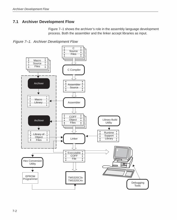
Archiver Development Flow
7-2
7.1 Archiver Development Flow
Figure 7–1 shows the archiver’s role in the assembly language developmentprocess. Both the assembler and the linker accept libraries as input.
Figure 7–1. Archiver Development Flow
Assembler
Linker
C Compiler
MacroLibrary
MacroSourceFiles
Library ofObjectFiles
Hex ConversionUtility
EPROMProgrammer
Debugging Tools
CSourceFiles
AssemblerSource
COFFObjectFiles
TMS320C3xTMS320C4x
ExecutableCOFF
File
RuntimeSupportLibrary
Archiver
Archiver Library Build Utility
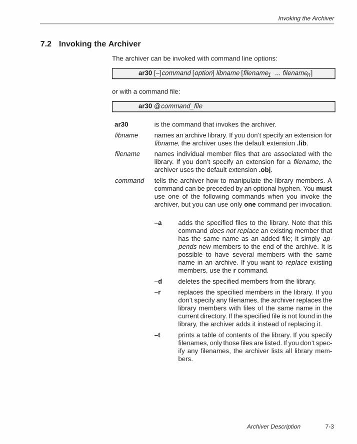
Invoking the Archiver
7-3Archiver Description
7.2 Invoking the Archiver
The archiver can be invoked with command line options:
ar30 [–]command [option] libname [filename1 ... filenamen]
or with a command file:
ar30 @command_file
ar30 is the command that invokes the archiver.
libname names an archive library. If you don’t specify an extension forlibname, the archiver uses the default extension .lib .
filename names individual member files that are associated with thelibrary. If you don’t specify an extension for a filename, thearchiver uses the default extension .obj .
command tells the archiver how to manipulate the library members. Acommand can be preceded by an optional hyphen. You mustuse one of the following commands when you invoke thearchiver, but you can use only one command per invocation.
–a adds the specified files to the library. Note that thiscommand does not replace an existing member thathas the same name as an added file; it simply ap-pends new members to the end of the archive. It ispossible to have several members with the samename in an archive. If you want to replace existingmembers, use the r command.
–d deletes the specified members from the library.
–r replaces the specified members in the library. If youdon’t specify any filenames, the archiver replaces thelibrary members with files of the same name in thecurrent directory. If the specified file is not found in thelibrary, the archiver adds it instead of replacing it.
–t prints a table of contents of the library. If you specifyfilenames, only those files are listed. If you don’t spec-ify any filenames, the archiver lists all library mem-bers.
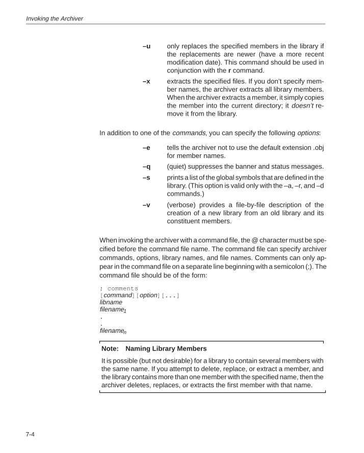
Invoking the Archiver
7-4
–u only replaces the specified members in the library ifthe replacements are newer (have a more recentmodification date). This command should be used inconjunction with the r command.
–x extracts the specified files. If you don’t specify mem-ber names, the archiver extracts all library members.When the archiver extracts a member, it simply copiesthe member into the current directory; it doesn’t re-move it from the library.
In addition to one of the commands, you can specify the following options:
–e tells the archiver not to use the default extension .objfor member names.
–q (quiet) suppresses the banner and status messages.
–s prints a list of the global symbols that are defined in thelibrary. (This option is valid only with the –a, –r, and –dcommands.)
–v (verbose) provides a file-by-file description of thecreation of a new library from an old library and itsconstituent members.
When invoking the archiver with a command file, the @ character must be spe-cified before the command file name. The command file can specify archivercommands, options, library names, and file names. Comments can only ap-pear in the command file on a separate line beginning with a semicolon (;). Thecommand file should be of the form:
; comments[ command][ option][...]libnamefilename1..filenamen
Note: Naming Library Members
It is possible (but not desirable) for a library to contain several members withthe same name. If you attempt to delete, replace, or extract a member, andthe library contains more than one member with the specified name, then thearchiver deletes, replaces, or extracts the first member with that name.
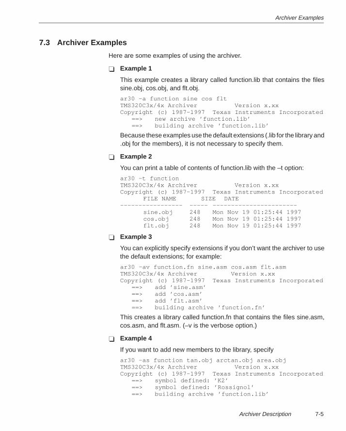
Archiver Examples
7-5Archiver Description
7.3 Archiver Examples
Here are some examples of using the archiver.
� Example 1
This example creates a library called function.lib that contains the filessine.obj, cos.obj, and flt.obj.
ar30 –a function sine cos fltTMS320C3x/4x Archiver Version x.xxCopyright (c) 1987–1997 Texas Instruments Incorporated
==> new archive ’function.lib’==> building archive ’function.lib’
Because these examples use the default extensions (.lib for the library and.obj for the members), it is not necessary to specify them.
� Example 2
You can print a table of contents of function.lib with the –t option:
ar30 –t function TMS320C3x/4x Archiver Version x.xxCopyright (c) 1987–1997 Texas Instruments Incorporated
FILE NAME SIZE DATE––––––––––––––––– ––––– –––––––––––––––––––––––
sine.obj 248 Mon Nov 19 01:25:44 1997cos.obj 248 Mon Nov 19 01:25:44 1997flt.obj 248 Mon Nov 19 01:25:44 1997
� Example 3
You can explicitly specify extensions if you don’t want the archiver to usethe default extensions; for example:
ar30 –av function.fn sine.asm cos.asm flt.asmTMS320C3x/4x Archiver Version x.xxCopyright (c) 1987–1997 Texas Instruments Incorporated
==> add ’sine.asm’==> add ’cos.asm’==> add ’flt.asm’==> building archive ’function.fn’
This creates a library called function.fn that contains the files sine.asm,cos.asm, and flt.asm. (–v is the verbose option.)
� Example 4
If you want to add new members to the library, specify
ar30 –as function tan.obj arctan.obj area.objTMS320C3x/4x Archiver Version x.xxCopyright (c) 1987–1997 Texas Instruments Incorporated
==> symbol defined: ’K2’==> symbol defined: ’Rossignol’==> building archive ’function.lib’
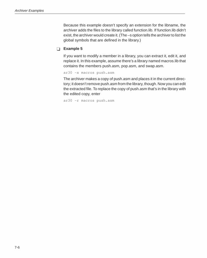
Archiver Examples
7-6
Because this example doesn’t specify an extension for the libname, thearchiver adds the files to the library called function.lib. If function.lib didn’texist, the archiver would create it. (The –s option tells the archiver to list theglobal symbols that are defined in the library.)
� Example 5
If you want to modify a member in a library, you can extract it, edit it, andreplace it. In this example, assume there’s a library named macros.lib thatcontains the members push.asm, pop.asm, and swap.asm.
ar30 –x macros push.asm
The archiver makes a copy of push.asm and places it in the current direc-tory; it doesn’t remove push.asm from the library, though. Now you can editthe extracted file. To replace the copy of push.asm that’s in the library withthe edited copy, enter
ar30 –r macros push.asm
8-1Linker Description
Linker Description
The TMS320C3x/C4x linker creates executable modules by combining COFFobject files. As the linker combines object files, it performs the following tasks:
� It allocates sections into the target system’s configured memory.� It relocates symbols and sections to assign them to final addresses.� It resolves undefined external references between input files.
The linker supports a command language that controls memory configuration,output section definition, and address binding. The language supportsexpression assignment and evaluation and provides two powerful directives,MEMORY and SECTIONS, that allow you to:
� Define a memory model that conforms to target system memory,� Combine object file sections,� Allocate sections into specific areas of memory, and� Define or redefine global symbols at link time.
Topic Page
8.1 Linker Development Flow 8-2. . . . . . . . . . . . . . . . . . . . . . . . . . . . . . . . . . . . . . 8.2 Invoking the Linker 8-4. . . . . . . . . . . . . . . . . . . . . . . . . . . . . . . . . . . . . . . . . . . . 8.3 Linker Options 8-6. . . . . . . . . . . . . . . . . . . . . . . . . . . . . . . . . . . . . . . . . . . . . . . . 8.4 Linker Command Files 8-18. . . . . . . . . . . . . . . . . . . . . . . . . . . . . . . . . . . . . . . 8.5 Object Libraries 8-21. . . . . . . . . . . . . . . . . . . . . . . . . . . . . . . . . . . . . . . . . . . . . . 8.6 The MEMORY Directive 8-23. . . . . . . . . . . . . . . . . . . . . . . . . . . . . . . . . . . . . . . 8.7 The SECTIONS Directive 8-27. . . . . . . . . . . . . . . . . . . . . . . . . . . . . . . . . . . . . . 8.8 Specifying a Section’s Runtime Address 8-35. . . . . . . . . . . . . . . . . . . . . . . 8.9 Using UNION and GROUP Statements 8-39. . . . . . . . . . . . . . . . . . . . . . . . . 8.10 Overlay Pages 8-42. . . . . . . . . . . . . . . . . . . . . . . . . . . . . . . . . . . . . . . . . . . . . . . 8.11 Default Allocation 8-47. . . . . . . . . . . . . . . . . . . . . . . . . . . . . . . . . . . . . . . . . . . . 8.12 Special Section Types (DSECT, COPY, and NOLOAD) 8-49. . . . . . . . . . . 8.13 Assigning Symbols at Link Time 8-50. . . . . . . . . . . . . . . . . . . . . . . . . . . . . . 8.14 Creating and Filling Holes 8-54. . . . . . . . . . . . . . . . . . . . . . . . . . . . . . . . . . . . 8.15 Partial (Incremental) Linking 8-58. . . . . . . . . . . . . . . . . . . . . . . . . . . . . . . . . . 8.16 Linking C Code 8-60. . . . . . . . . . . . . . . . . . . . . . . . . . . . . . . . . . . . . . . . . . . . . . 8.17 Linker Example 8-64. . . . . . . . . . . . . . . . . . . . . . . . . . . . . . . . . . . . . . . . . . . . . .
Chapter 8
Linker Development Flow
8-2
8.1 Linker Development Flow
Figure 8–1 illustrates the linker’s role in the assembly language developmentprocess. The linker accepts several types of files as input, including objectfiles, command files, libraries, and partially linked files. The linker creates anexecutable COFF object module that can be downloaded to one of several de-velopment tools or executed by a TMS320C3x/C4x device.
Input files generated by TMS320C3x/C4x tools can be created on any sup-ported host machine and then linked by the TMS320C3x/C4x linker on adifferent machine. For example, an input file assembled by theTMS320C3x/C4x assembler on a PC can be linked by the TMS320C3x/C4xlinker on a SPARCstation. If a TMS320C3x/C4x tool was not used to createan input file, the file must have the appropriate byte–swapping done before itcan be linked on a different machine.
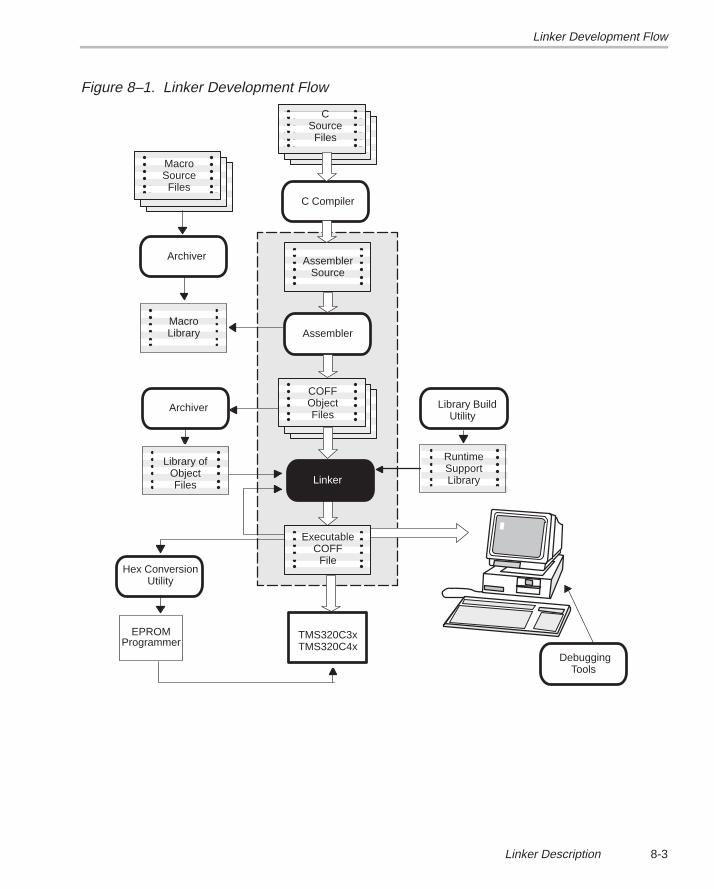
Linker Development Flow
8-3Linker Description
Figure 8–1. Linker Development Flow
Assembler
C Compiler
Archiver
MacroLibrary
MacroSourceFiles
Archiver
Library ofObjectFiles
Hex ConversionUtility
EPROMProgrammer
Debugging Tools
CSourceFiles
AssemblerSource
COFFObjectFiles
TMS320C3xTMS320C4x
ExecutableCOFF
File
RuntimeSupportLibraryLinker
Library Build Utility
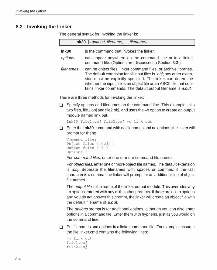
Invoking the Linker
8-4
8.2 Invoking the LinkerThe general syntax for invoking the linker is:
lnk30 [–options] filename1 ... filenamen
lnk30 is the command that invokes the linker.
options can appear anywhere on the command line or in a linkercommand file. (Options are discussed in Section 8.3.)
filenames can be object files, linker command files, or archive libraries.The default extension for all input files is .obj ; any other exten-sion must be explicitly specified. The linker can determinewhether the input file is an object file or an ASCII file that con-tains linker commands. The default output filename is a.out.
There are three methods for invoking the linker:
� Specify options and filenames on the command line. This example linkstwo files, file1.obj and file2.obj, and uses the –o option to create an outputmodule named link.out.
lnk30 file1.obj file2.obj –o link.out
� Enter the lnk30 command with no filenames and no options; the linker willprompt for them:
Command files :Object files [.obj] :Output files [ ] :Options :
For command files, enter one or more command file names.
For object files, enter one or more object file names. The default extensionis .obj. Separate the filenames with spaces or commas; if the lastcharacter is a comma, the linker will prompt for an additional line of objectfile names.
The output file is the name of the linker output module. This overrides any–o options entered with any of the other prompts. If there are no –o optionsand you do not answer this prompt, the linker will create an object file withthe default filename of a.out .
The options prompt is for additional options, although you can also enteroptions in a command file. Enter them with hyphens, just as you would onthe command line.
� Put filenames and options in a linker command file. For example, assumethe file linker.cmd contains the following lines:
–o link.outfile1.objfile2.obj
Invoking the Linker
8-5Linker Description
Now you can invoke the linker from the command line; specify the com-mand file name as an input file:
lnk30 linker.cmd
When you use a command file, you can also specify other options and fileson the command line. For example, you could enter:
lnk30 –m link.map linker.cmd file3.obj
The linker reads and processes a command file as soon as it encounters iton the command line, so it links the files in this order: file1.obj, file2.obj, andfile3.obj. This example creates an output file called link.out and a map filecalled link.map.
Note: Version Number Not Required for Linker
The linker does not have a version option to specify the target CPU. Thetarget CPU type is encoded in the object files and the linker automaticallylinks for the correct processor. The linker will issue an error message if youattempt to link object files assembled for different processors.
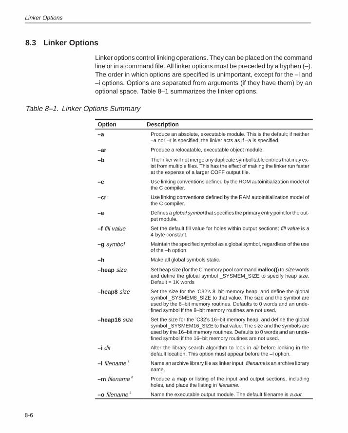
Linker Options
8-6
8.3 Linker Options
Linker options control linking operations. They can be placed on the commandline or in a command file. All linker options must be preceded by a hyphen (–).The order in which options are specified is unimportant, except for the –l and–i options. Options are separated from arguments (if they have them) by anoptional space. Table 8–1 summarizes the linker options.
Table 8–1. Linker Options Summary
Option Description
–a Produce an absolute, executable module. This is the default; if neither–a nor –r is specified, the linker acts as if –a is specified.
–ar Produce a relocatable, executable object module.
–b The linker will not merge any duplicate symbol table entries that may ex-ist from multiple files. This has the effect of making the linker run fasterat the expense of a larger COFF output file.
–c Use linking conventions defined by the ROM autoinitialization model ofthe C compiler.
–cr Use linking conventions defined by the RAM autoinitialization model ofthe C compiler.
–e Defines a global symbol that specifies the primary entry point for the out-put module.
–f fill value Set the default fill value for holes within output sections; fill value is a4-byte constant.
–g symbol Maintain the specified symbol as a global symbol, regardless of the useof the –h option.
–h Make all global symbols static.
–heap size Set heap size (for the C memory pool command malloc() ) to size wordsand define the global symbol _SYSMEM_SIZE to specify heap size.Default = 1K words
–heap8 size Set the size for the ’C32’s 8–bit memory heap, and define the globalsymbol _SYSMEM8_SIZE to that value. The size and the symbol areused by the 8–bit memory routines. Defaults to 0 words and an unde-fined symbol if the 8–bit memory routines are not used.
–heap16 size Set the size for the ’C32’s 16–bit memory heap, and define the globalsymbol _SYSMEM16_SIZE to that value. The size and the symbols areused by the 16–bit memory routines. Defaults to 0 words and an unde-fined symbol if the 16–bit memory routines are not used.
–i dir Alter the library-search algorithm to look in dir before looking in thedefault location. This option must appear before the –l option.
–l filename † Name an archive library file as linker input; filename is an archive libraryname.
–m filename † Produce a map or listing of the input and output sections, includingholes, and place the listing in filename.
–o filename † Name the executable output module. The default filename is a.out.
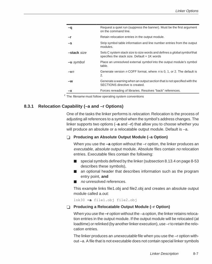
Linker Options
8-7Linker Description
–q Request a quiet run (suppress the banner). Must be the first argumenton the command line.
–r Retain relocation entries in the output module.
–s Strip symbol table information and line number entries from the outputmodules.
–stack size Sets C system stack size to size words and defines a global symbol thatspecifies the stack size. Default = 1K words
–u symbol Place an unresolved external symbol into the output module’s symboltable.
–vn Generate version n COFF format, where n is 0, 1, or 2. The default is2.
–w Generate a warning when an output section that is not specified with theSECTIONS directive is created.
–x Forces rereading of libraries. Resolves “back” references.
† The filename must follow operating system conventions
8.3.1 Relocation Capability (–a and –r Options)
One of the tasks the linker performs is relocation. Relocation is the process ofadjusting all references to a symbol when the symbol’s address changes. Thelinker supports two options (–a and –r) that allow you to choose whether youwill produce an absolute or a relocatable output module. Default is –a.
� Producing an Absolute Output Module (–a Option)
When you use the –a option without the –r option, the linker produces anexecutable, absolute output module. Absolute files contain no relocationentries. Executable files contain the following:
� special symbols defined by the linker (subsection 8.13.4 on page 8-53describes these symbols),
� an optional header that describes information such as the programentry point, and
� no unresolved references.
This example links file1.obj and file2.obj and creates an absolute outputmodule called a.out:
lnk30 –a file1.obj file2.obj
� Producing a Relocatable Output Module (–r Option)
When you use the –r option without the –a option, the linker retains reloca-tion entries in the output module. If the output module will be relocated (atloadtime) or relinked (by another linker execution), use –r to retain the relo-cation entries.
The linker produces an unexecutable file when you use the –r option with-out –a. A file that is not executable does not contain special linker symbols
Linker Options
8-8
or an optional header. The file may contain unresolved references, butthese references do not prevent creation of an output module.
This example links file1.obj and file2.obj and creates a relocatable outputmodule called a.out:
lnk30 –r file1.obj file2.obj
The output file a.out can be relinked with other object files or relocated atloadtime. (Linking a file that will be relinked with other files is called partiallinking. For more information, see Section 8.15 on page 8-58.)
� Producing an Executable Relocatable Output Module (–ar)
If you invoke the linker with both the –a and –r options, the linker producesan executable, relocatable object module. The output file contains thespecial linker symbols and an optional header. All symbol references areresolved (this is normal for a relocatable file); however, the relocationinformation is retained.
This example links file1.obj and file2.obj and creates an executable,relocatable output module called xr.out:
lnk30 –ar file1.obj file2.obj –o xr.out
Note that you can string the options together (lnk30 –ar) or you can enterthem separately (lnk30 –a –r).
� Relocating or Relinking an Absolute Output Module
The linker issues a warning message (but continues executing) when itencounters a file that contains no relocation or symbol table information.Relinking an absolute file can be successful only if each input file containsno information that needs to be relocated (that is, each file has nounresolved references and is bound to the same virtual address that it wasbound to when the linker created it).
Linker Options
8-9Linker Description
8.3.2 Disable Merge of Symbolic Debugging Information (–b Option)
By default, the linker eliminates duplicate entries of symbolic debugginginformation. Such duplicate information is commonly generated when a C pro-gram is compiled for debugging. For example:
– [ header.h ] –typedef struct{ <define some structure members>} XYZ;
– [ fl.c ] –#include “header.h”...
– [ f2.c ] –#include “header.h”...
When these files are compiled for debugging, both f1.obj and f2.obj will havesymbolic debugging entries to describe type XYZ. For the final output file, onlyone set of these entries is necessary. The linker will eliminate the duplicate en-tries automatically.
Using the –b option causes the linker to keep such duplicate entries. Keepingthese entries allows the linker to run faster and use less machine memory atthe expense of producing a larger COFF output file.
8.3.3 C Language Options (–c and –cr Options)
The –c and –cr options cause the linker to use linking conventions that arerequired by the TMS320C3x/C4x C compiler.
� The –c option tells the linker to use the ROM autoinitialization model.
� The –cr option tells the linker to use the RAM autoinitialization model.
For more information about linking C code, see Section 8.16 on page 8-60.
8.3.4 Define an Entry Point (–e global symbol Option)
The memory address that a program begins executing from is called the entrypoint. When a loader loads a program into target memory, the programcounter must be initialized to the entry point; the PC then points to the begin-ning of the program.
The linker can assign one of four possible values to the entry point. These val-ues are listed below in the order in which the linker tries to use them. If you use
Linker Options
8-10
one of the first three values, it must be an external symbol in the symbol table.Possible entry point values include:
� The value specified by the –e option. The syntax is –e global symbol whereglobal symbol defines the entry point and must appear as an external sym-bol in one of the input files to be linked.
� The value of symbol _c_int00 (if present). _c_int00 must be the entrypoint if you are linking code produced by the C compiler.
� The value of symbol _main (if present).
� Zero (default value).
This example links file1.obj and file2.obj and sets the entry point to the valueof the symbol begin. This symbol must be defined as external in file1 or file2.
lnk30 –e begin file1.obj file2.obj
8.3.5 Set Default Fill Value (–f cc Option)
The –f option fills the holes formed within output sections or initializes uninitial-ized sections when they are combined with initialized sections. This allows youto initialize memory areas during link time without reassembling a source file.The argument cc is a 4-byte constant (up to eight hexadecimal digits). If youdo not use –f, the linker uses 0 as the default fill value.
This example fills holes with the hexadecimal value AABBCCDDh:
lnk30 –f 0AABBCCDDh file1.obj file2.obj
For more information about holes, see Section 8.14 on page 8-54.
8.3.6 Make All Global Symbols Static (–h Option)
The –h option makes output global symbols static. This is useful when you areusing partial linking to link related object files into self-contained modules, thenrelinking the modules into a final system. If there are global symbols in onemodule that have the same name as global symbols in other modules, but youwant to treat them as separate symbols, use the –h option when building themodules. The global symbols in the modules, which would normally be visibleto the other modules and cause possible redefinition problems in the final link,are made static so that they are not visible to the other modules.
For example, assume b1.obj, b2.obj, and b3.obj are related and reference aglobal variable GLOB. Also assume that d1.obj, d2.obj, and d3.obj are relatedand also reference a separate global variable GLOB. You can link the relatedfiles with the following commands:
Linker Options
8-11Linker Description
lnk30 –h –r b1.obj b2.obj b3.obj –o bpart.outlnk30 –h –r d1.obj d2.obj d3.obj –o dpart.out
The –h option guarantees that bpart.out and dpart.out will not have globalsymbols and therefore two distinct versions of GLOB exist. The –r option isused to allow bpart.out and dpart.out to retain their relocation entries. Thesetwo partially linked files can then be safely linked with the following command:
lnk30 bpart.out dpart.out –o system.out
For more information about partial linking, see Section 8.15 on page 8-58.
8.3.7 Keep a Global Symbol (–g symbol Option)
The –g option allows you to keep the named symbol as a non–static globalsymbol, despite the use of the –h option. This allows the sharing of specificsymbols across multiple object files with variables of the same name. Any sym-bols of the specified name will be visible to all modules, and an error will resultif the symbol has a definition in more than one file.
8.3.8 Define Heap Size (–heap size, –heap8 size, and –heap16 size Options)
The TMS320C3x/C4x C compiler uses an uninitialized section called .sysmemfor the C runtime memory pool used by malloc(). You can set the size of thismemory pool at link time by using the –heap option. Specify the size in wordsas a four byte constant immediately after the option:
lnk30 –heap 0x4000 /* defines a 256K byte heap (.sysmem section)*/
The linker creates the .sysmem section only if there is a .sysmem section inan input file.
The linker also creates a global symbol __SYSMEM_SIZE and assigns it avalue equal to the size of the heap. The default size is 1K words.
To support the TMS320C32, the ’C3x runtime support library adds 8-bit and16-bit versions of the dynamic memory management functions. These func-tions are analogous to the 32-bit versions described in Chapter 5, RuntimeSupport Functions, of the TMS320C3x/C4x Optimizing C Compiler User’sGuide. The only difference is that the 8-bit and 16-bit versions allocate spacefrom the .sysm8 and .sysm16 uninitialized sections rather than the .sysmemsection.
Linker Options
8-12
void *calloc8(size_t _num, size_t _size);void free8(void *_ptr);void *malloc8(size_t _size);void *bmalloc8(size_t _size);void minit8(void);void *realloc8(void *_ptr, size_t _size);
void *calloc16(size_t _num, size_t _size);void free16(void *_ptr);void *malloc16(size_t _size);void *bmalloc16(size_t _size);void minit16(void);void *realloc16(void *_ptr, size_t _size);
The sizes of the .sysm8 and .sysm16 sections can be set by using the –heap8and –heap16 linker options, respectively. If the memory management func-tions are used but the –heap8 and –heap16 options are not used, the defaultsize of each heap is 1K words. If the memory management functions are notused, the linker will not allocate the .sysm8 and .sysm16 sections. If thesections are created, the linker sets the constant heap size values in the_SYSMEM8_SIZE and _SYSMEM16_SIZE symbols, respectively. Thestdlib.h header file should be included in any file that uses these new functions.
For more information about linking C code, see Section 8.16 on page 8-60.
8.3.9 Alter the Library Search Algorithm (–i dir & –l filename /C_DIR)
Usually when you want to specify a library input, you simply enter the libraryname as you would any other input filename; the linker looks for the library inthe current directory. For example, suppose the current directory contains thelibrary object.lib. Assume that this library defines symbols that are referencedin the file file1.obj. This is how you link the files:
lnk30 file1.obj object.lib
If you want to use a library that is not in the current directory, use the –l (lower-case “L”) linker option. The syntax for this option is –l filename. The filenameis the name of an archive library; the space between –l and the filename is op-tional.
You can augment the linker’s directory search algorithm by using the –i linkeroption or the environment variable. The linker searches for any file specifiedwith –l in the following order:
1) It searches directories named with the –i linker option.2) It searches directories named with the environment variable C_DIR.3) If C_DIR is not set, it searches directories named with the assembler’s en-
vironment variable, A_DIR.4) It searches the current directory.

Linker Options
8-13Linker Description
8.3.10 –i Linker Option
The –i option names an alternate directory that contains object libraries. Thesyntax for this option is –i dir. dir names a directory that contains object librar-ies; the space between –i and the directory name is optional. When the linkeris searching for object libraries named with the –l option, it searches throughdirectories named with –i first. Each –i option specifies only one directory, butyou can use several –i options per invocation. When you use the –i option toname an alternate directory, it must precede the –l option on the command lineor in a command file.
As an example, assume that there are two archive libraries called r.lib andlib2.lib. The table below shows the directories that r.lib and lib2.lib reside in,how to set environment variable, and how to use both libraries during a link.Select the row for your operating system:
Sample Pathname Invocation Command
DOS \c30 and \c302 lnk30 f1.obj f2.obj –i\c30 –i\c302 –l r.lib –l lib2.lib
UNIX /c30 and /c302 lnk30 f1.obj f2.obj –i/c30 –i/c302 –l r.lib –l lib2.lib
8.3.11 Environment Variable (C_DIR or A_DIR)
An environment variable is a system symbol that you define and assign a stringto. The linker uses an environment variable named C_DIR to name alternatedirectories that contain object libraries. The command for assigning the envi-ronment variable is:
Sample Pathname Invocation Command
DOS \dsp and \dsp2 set C_DIR=\dsp;\dsp2lnk30 f1.obj f2.obj –l r.lib –l lib2.lib
UNIX /dsp and /dsp2 setenv C_DIR /dsp:/dsp2lnk30 f1.obj f2.obj –l r.lib –l lib2.lib
The pathnames are directories that contain object libraries. Use the –l optionon the command line or in a command file to tell the linker which libraries tosearch for.
The assembler uses an environment variable named A_DIR to name alternatedirectories that contain copy/include files or macro libraries. If C_DIR is not set,the linker will search for object libraries in the directories named with A_DIR.Section 8.5 (page 8-21) contains more information about object libraries.
Linker Options
8-14
8.3.12 Create a Map File (–m filename Option)
The –m option creates a link map listing and puts it in filename. This map de-scribes:
� Memory configuration
� Input and output section allocation
� The addresses of external symbols after they have been relocated
The map file contains the name of the output module and the entry point; it mayalso contain up to three tables:
� A table showing the memory configuration, if any nondefault memory isspecified.
� A table showing the linked addresses of each output section and the inputsections that make up the output sections.
� A table showing each external symbol and its address. This table has twocolumns: the left column contains the symbols sorted by name, and theright column contains the symbols sorted by address.
This example links file1.obj and file2.obj and creates a map file called map.out:
lnk30 file1.obj file2.obj –m map.out
Section 8.17 (page 8-64) shows an example of a map file.
8.3.13 Name an Output Module (–o filename Option)
The linker creates an executable output module. If you do not specify a file-name for the output module, the linker gives it the default name a.out . If youwant to the output module to have another name, use the –o option. The file-name is the new output module name.
This example links file1.obj and file2.obj and creates an output module namedrun.out:
lnk30 –o run.out file1.obj file2.obj
8.3.14 Specify a Quiet Run (–q Option)
The –q option suppresses the linker’s banner when –q is the first option on thecommand line or in a command file. This option is useful for batch operation.
8.3.15 Strip Symbolic Information (–s Option)
The –s option creates a smaller output module by omitting symbol table infor-mation and line number entries. The –s option is useful for production applica-tions when you must create the smallest possible output module.
Linker Options
8-15Linker Description
This example links file1.obj and file2.obj and places them in an output module,stripped of line numbers and symbol table information, named nolink.out:
lnk30 –o nolink.out –s file1.obj file2.obj
Note that using the –s option limits later use of a symbolic debugger and mayprevent a file from being relinked.
8.3.16 Define Stack Size (–stack size Option)
The TMS320C3x/C4x C compiler uses an uninitialized section, .stack, toallocate space for the runtime stack. You can set the size of the .stack sectionat link time with the –stack option. Specify the size in words as a constantimmediately after the option:
lnk30 –stack 0x1000 /* defines a 4K stack (.stack section) */
If you specified a different stack size in an input section, the input section stacksize is ignored. Any symbols defined in the input section remain valid; only thestack size will be different.
When the linker defines the .stack section, it also defines a global symbol,_ _STACK_SIZE, and assigns it a value equal to the size of the section. Thedefault stack size is 1K words.
8.3.17 Introduce an Unresolved Symbol (–u symbol Option)
The –u option introduces an unresolved symbol into the linker’s symbol table.This forces the linker to search through a library and include the module thatdefines the symbol. Note that the linker must encounter the –u option beforeit links in the member that defines the symbol.
For example, suppose a library named sym.lib contains a member that definesthe symbol symtab; none of the object files you are linking reference to symtab.However, suppose you plan to relink the output module, and you would like toinclude the library member that defines symtab in this link. Using the –u optionas shown below forces the linker to search sym.lib for the member that definessymtab and to link in the member.
lnk30 –u symtab file1.obj file2.obj sym.lib
If you do not use –u, this member would not be included because there is noexplicit reference to it from file1.obj or file2.obj.
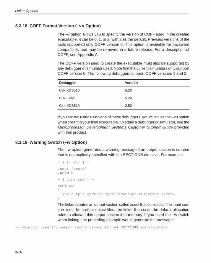
Linker Options
8-16
8.3.18 COFF Format Version (–v n Option)
The –v option allows you to specify the version of COFF used in the createdexecutable. n can be 0, 1, or 2, with 2 as the default. Previous versions of thetools supported only COFF version 0. This option is available for backwardcompatibility and may be removed in a future release. For a description ofCOFF, see Appendix A.
The COFF version used to create the executable must also be supported byany debugger or simulator used. Note that the current simulators only supportCOFF version 0. The following debuggers support COFF versions 1 and 2:
Debugger Version
C3x XDS510 5.20
C3x EVM 5.20
C4x XDS510 2.50
If you are not using using one of these debuggers, you must use the –v0 optionwhen creating your final executable. To attain a debugger or simulator, see theMicroprocessor Development Systems Customer Support Guide providedwith this product.
8.3.19 Warning Switch (–w Option)
The –w option generates a warning message if an output section is createdthat is not explicitly specified with the SECTIONS directive. For example:
– [ fl.asm ] –
.sect “xsect”
.word 0
– [ link.cmd ] –
SECTIONS{ <no output section specifications reference xsect>}
The linker creates an output section called xsect that consists of the input sec-tion xsect from other object files; the linker then uses the default allocationrules to allocate this output section into memory. If you used the –w switchwhen linking, the preceding example would generate the message:
>> warning: creating output section xsect without SECTIONS specification
Linker Options
8-17Linker Description
8.3.20 Exhaustively Read Libraries (–x option)
The linker normally reads input files, archive libraries included, only once whenthey are encountered on the command line or in the command file. When anarchive is read, any members that resolve references to undefined symbolsare included in the link. If an input file later references a symbol defined in apreviously read archive library (this is called a back reference), the referencewill not be resolved.
You can force the linker to repeatedly reread all libraries with the –x option. Thelinker will continue to reread libraries until no more references can be resolved.For example, if a.lib contains a reference to a symbol defined in b.lib, and b.libcontains a reference to a symbol defined in a.lib, you can resolve the mutualdependencies by listing one of the libraries twice, as in:
lnk30 –la.lib –lb.lib –la.lib
or you can force the linker to do it for you:
lnk30 –x –la.lib –lb.lib
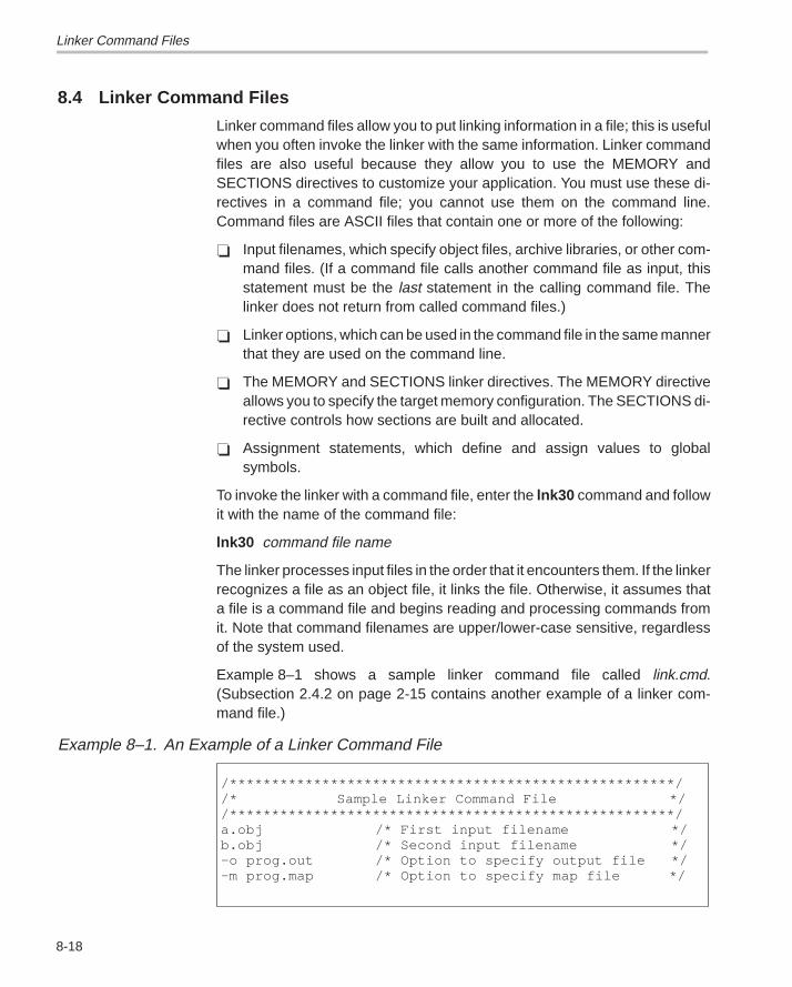
Linker Command Files
8-18
8.4 Linker Command Files
Linker command files allow you to put linking information in a file; this is usefulwhen you often invoke the linker with the same information. Linker commandfiles are also useful because they allow you to use the MEMORY andSECTIONS directives to customize your application. You must use these di-rectives in a command file; you cannot use them on the command line.Command files are ASCII files that contain one or more of the following:
� Input filenames, which specify object files, archive libraries, or other com-mand files. (If a command file calls another command file as input, thisstatement must be the last statement in the calling command file. Thelinker does not return from called command files.)
� Linker options, which can be used in the command file in the same mannerthat they are used on the command line.
� The MEMORY and SECTIONS linker directives. The MEMORY directiveallows you to specify the target memory configuration. The SECTIONS di-rective controls how sections are built and allocated.
� Assignment statements, which define and assign values to globalsymbols.
To invoke the linker with a command file, enter the lnk30 command and followit with the name of the command file:
lnk30 command file name
The linker processes input files in the order that it encounters them. If the linkerrecognizes a file as an object file, it links the file. Otherwise, it assumes thata file is a command file and begins reading and processing commands fromit. Note that command filenames are upper/lower-case sensitive, regardlessof the system used.
Example 8–1 shows a sample linker command file called link.cmd.(Subsection 2.4.2 on page 2-15 contains another example of a linker com-mand file.)
Example 8–1. An Example of a Linker Command File
/*****************************************************//* Sample Linker Command File *//*****************************************************/a.obj /* First input filename */b.obj /* Second input filename */–o prog.out /* Option to specify output file */–m prog.map /* Option to specify map file */
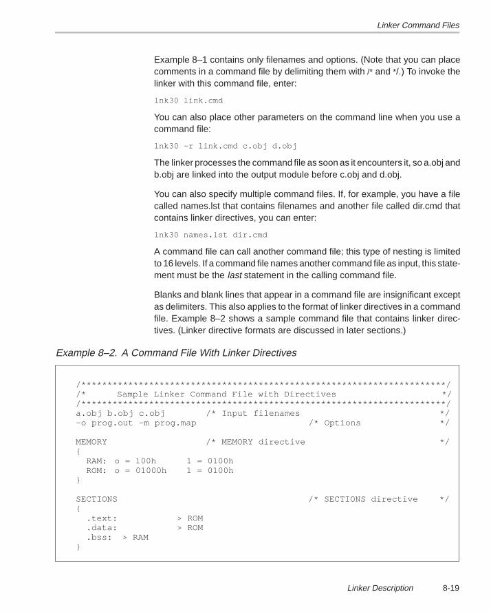
Linker Command Files
8-19Linker Description
Example 8–1 contains only filenames and options. (Note that you can placecomments in a command file by delimiting them with /* and */.) To invoke thelinker with this command file, enter:
lnk30 link.cmd
You can also place other parameters on the command line when you use acommand file:
lnk30 –r link.cmd c.obj d.obj
The linker processes the command file as soon as it encounters it, so a.obj andb.obj are linked into the output module before c.obj and d.obj.
You can also specify multiple command files. If, for example, you have a filecalled names.lst that contains filenames and another file called dir.cmd thatcontains linker directives, you can enter:
lnk30 names.lst dir.cmd
A command file can call another command file; this type of nesting is limitedto 16 levels. If a command file names another command file as input, this state-ment must be the last statement in the calling command file.
Blanks and blank lines that appear in a command file are insignificant exceptas delimiters. This also applies to the format of linker directives in a commandfile. Example 8–2 shows a sample command file that contains linker direc-tives. (Linker directive formats are discussed in later sections.)
Example 8–2. A Command File With Linker Directives
/**********************************************************************//* Sample Linker Command File with Directives *//**********************************************************************/a.obj b.obj c.obj /* Input filenames */–o prog.out –m prog.map /* Options */
MEMORY /* MEMORY directive */{
RAM: o = 100h 1 = 0100hROM: o = 01000h 1 = 0100h
}
SECTIONS /* SECTIONS directive */{
.text: > ROM
.data: > ROM
.bss: > RAM}
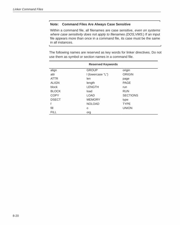
Linker Command Files
8-20
Note: Command Files Are Always Case Sensitive
Within a command file, all filenames are case sensitive, even on systemswhere case sensitivity does not apply to filenames (DOS,VMS.) If an inputfile appears more than once in a command file, its case must be the samein all instances.
The following names are reserved as key words for linker directives. Do notuse them as symbol or section names in a command file.
Reserved Keywords
align GROUP originattr l (lowercase “L”) ORIGINATTR len pageALIGN length PAGEblock LENGTH runBLOCK load RUNCOPY LOAD SECTIONSDSECT MEMORY typef NOLOAD TYPEfill o UNIONFILL org
Object Libraries
8-21Linker Description
8.5 Object Libraries
An object library is a partitioned archive file that contains complete object filesas members. Usually, a group of related modules are grouped together intoa library. When you specify an object library as linker input, the linker includesany members of the library that define existing unresolved symbol references.You can use the TMS320C3x/C4x archiver to build and maintain archivelibraries; Chapter 7 contains more information about the archiver.
Using object libraries can reduce linking time and can reduce the size of theexecutable module. If a normal object file is specified at link time, it is linkedwhether it is used or not; however, if that same file is placed in an archivelibrary, it is included only if it is referenced.
The order in which libraries are specified is important because the linkerincludes only those members that resolve symbols that are undefined whenthe library is searched. The same library can be specified as often as neces-sary; it is searched each time it is included. An alternative is to use the –xoption, which continually searches all libraries until all references are resolved.A library has a table that lists all external symbols defined in the library; thelinker searches through the table until it determines that it cannot use thelibrary to resolve any more references.
The following example links several object files and libraries; assume the fol-lowing:
� Input files f1.obj and f2.obj both reference an external function namedclrscr.
� Input file f1.obj references the symbol origin.� Input file f2.obj references the symbol fillclr.� Library libc.lib, member 0, contains a definition of origin.� Library liba.lib, member 3, contains a definition of fillclr.� Member 1 of both libraries defines clrscr.
If you enter
lnk30 f1.obj liba.lib f2.obj libc.lib
then:
� Member 1 of liba.lib satisfies both references to clrscr, because the libraryis searched and clrscr is defined before f2.obj references it.
� Member 0 of libc.lib satisfies the reference to origin.� Member 3 of liba.lib satisfies the reference to fillclr.
Object Libraries
8-22
If, however, you enter:
lnk30 f1.obj f2.obj libc.lib liba.lib
then the references to clrscr are satisfied by member 1 of libc.lib.
If none of the linked files reference symbols defined in a library, you can usethe –u option to force the linker to include a library member. The next examplecreates an undefined symbol rout1 in the linker’s global symbol table:
lnk30 –u rout1 libc.lib
If any members of libc.lib define rout1, then the linker includes those members.Note that it is not possible to control the allocation of individual library mem-bers; members are allocated according to the SECTIONS directive default al-location algorithm.
Subsection 8.3.9 (page 8-12) describes methods for specifying directories thatcontain object libraries.
The MEMORY Directive
8-23Linker Description
8.6 The MEMORY Directive
The linker determines where output sections should be allocated into memory;the linker must have a model of target memory to accomplish this task. TheMEMORY directive allows you to specify a model of target memory, so you candefine the types of memory your system contains and the address ranges theyoccupy. The linker maintains the model as it allocates output sections, anduses the model to determine which memory locations in the target system canbe used for object code.
The memory configurations of TMS320 systems differ from application to ap-plication. The MEMORY directive allows you to specify a variety of configura-tions to meet all applications. After you use the MEMORY directive to definea memory model, you can use the SECTIONS directive to allocate output sec-tions into defined memory.
8.6.1 Default Memory Model
If you do not use the MEMORY directive, the linker uses a default memorymodel that is based on the TMS320C3x/C4x architecture. This model as-sumes that the full 32-bit address space (232 locations) is present in the systemand available for use.
8.6.2 MEMORY Directive Syntax
The MEMORY directive identifies ranges of memory that are physically pre-sent in the target system and can be used by a program. Each memory rangehas a name, a starting address, and a length.
When you use the MEMORY directive, be sure to identify all the memoryranges that are available to load object code into. Memory that is defined bythe MEMORY directive is configured memory; any memory that you do not ex-plicitly account for with the MEMORY directive is unconfigured memory. Thelinker does not place any part of a program into unconfigured memory. You canrepresent nonexistent memory spaces by simply not including an addressrange in a MEMORY directive statement.
The MEMORY directive is specified in a command file by the word MEMORY(uppercase), followed by a list of memory range specifications enclosed inbraces. The MEMORY directive in Example 8–3 defines a system that has 4Kwords of ROM at address 0 and 8K of RAM at address 0E000h.
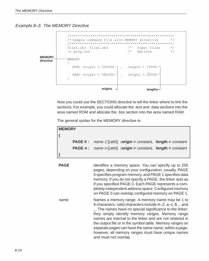
The MEMORY Directive
8-24
Example 8–3. The MEMORY Directive
/*************************************************//* Sample command file with MEMORY directive *//*************************************************/file1.obj file2.obj /* Input files */–o prog.out /* Options */
MEMORY{
ROM: origin = 00000h , length = 1000h
RAM: origin = 0E000h , length = 2000h}
origins lengths
MEMORYdirective
Now you could use the SECTIONS directive to tell the linker where to link thesections. For example, you could allocate the .text and .data sections into thearea named ROM and allocate the .bss section into the area named RAM.
The general syntax for the MEMORY directive is:
MEMORY
{
PAGE 0 : name 1 [(attr)] :origin = constant, length = constant
PAGE n : name n [(attr)] :origin = constant, length = constant
}
PAGE identifies a memory space. You can specify up to 255pages, depending on your configuration; usually, PAGE0 specifies program memory, and PAGE 1 specifies datamemory. If you do not specify a PAGE, the linker acts asif you specified PAGE 0. Each PAGE represents a com-pletely independent address space. Configured memoryon PAGE 0 can overlap configured memory on PAGE 1.
name Names a memory range. A memory name may be 1 to8 characters; valid characters include A–Z, a–z, $, ., and_. The names have no special significance to the linker;they simply identify memory ranges. Memory rangenames are internal to the linker and are not retained inthe output file or in the symbol table. Memory ranges onseparate pages can have the same name; within a page,however, all memory ranges must have unique namesand must not overlap.
The MEMORY Directive
8-25Linker Description
attr Specifies one to four attributes associated with thenamed range. Attributes are optional; when used, theymust be enclosed in parentheses. Attributes can restrictthe allocation of output sections into certain memoryranges. If you do not use any attributes, you can allocateany output section into any range with no restrictions.Any memory for which no attributes are specified (includ-ing all memory in the default model) has all four attrib-utes. Valid attributes include:
R specifies that the memory can be readW specifies that the memory can be written toX specifies that the memory can contain executable
codeI specifies that the memory can be initialized
If you do not specify any attributes for a memoryrange, then the range has all four attributes. All mem-ory in the default model has all four attributes. The fol-lowing example defines a memory range that is read-able and executable:
MEMORY{ ROM (RX) : o = 0, l = 01000h }
origin Specifies the starting address of a memory range; enteras origin, org, or o. The value, specified in bytes, is a16-bit constant and may be decimal, octal, or hexadeci-mal.
length Specifies the length of a memory range; enter as length,len, or l. The value, specified in bytes, is a 16 bit constantand may be decimal, octal, or hexadecimal.
fill Specifies a fill character for the memory range; enter asfill or f. Fills are optional. The value is a two-byte integerconstant and may be decimal, octal, or hexadecimal.The fill value will be used to fill areas of the memory rangethat are not allocated to a section.
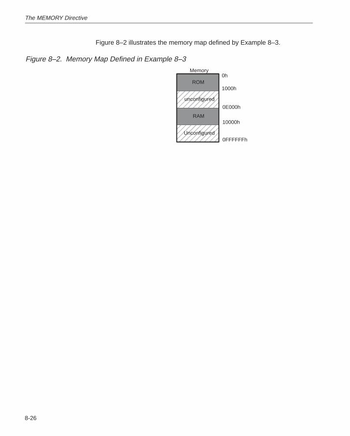
The MEMORY Directive
8-26
Figure 8–2 illustrates the memory map defined by Example 8–3.
Figure 8–2. Memory Map Defined in Example 8–3
ÉÉÉÉÉÉÉÉÉÉÉÉ
ÉÉÉÉÉÉÉÉÉÉÉÉÉÉÉÉÉÉ
0h
1000h
0E000h
10000h
0FFFFFFh
ROM
unconfigured
RAM
Unconfigured
Memory
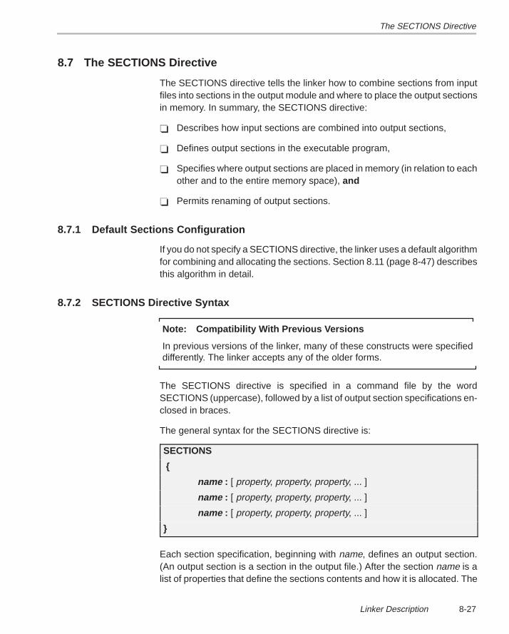
The SECTIONS Directive
8-27Linker Description
8.7 The SECTIONS Directive
The SECTIONS directive tells the linker how to combine sections from inputfiles into sections in the output module and where to place the output sectionsin memory. In summary, the SECTIONS directive:
� Describes how input sections are combined into output sections,
� Defines output sections in the executable program,
� Specifies where output sections are placed in memory (in relation to eachother and to the entire memory space), and
� Permits renaming of output sections.
8.7.1 Default Sections Configuration
If you do not specify a SECTIONS directive, the linker uses a default algorithmfor combining and allocating the sections. Section 8.11 (page 8-47) describesthis algorithm in detail.
8.7.2 SECTIONS Directive Syntax
Note: Compatibility With Previous Versions
In previous versions of the linker, many of these constructs were specifieddifferently. The linker accepts any of the older forms.
The SECTIONS directive is specified in a command file by the wordSECTIONS (uppercase), followed by a list of output section specifications en-closed in braces.
The general syntax for the SECTIONS directive is:
SECTIONS
{
name : [ property, property, property, ... ]
name : [ property, property, property, ... ]
name : [ property, property, property, ... ]
}
Each section specification, beginning with name, defines an output section.(An output section is a section in the output file.) After the section name is alist of properties that define the sections contents and how it is allocated. The
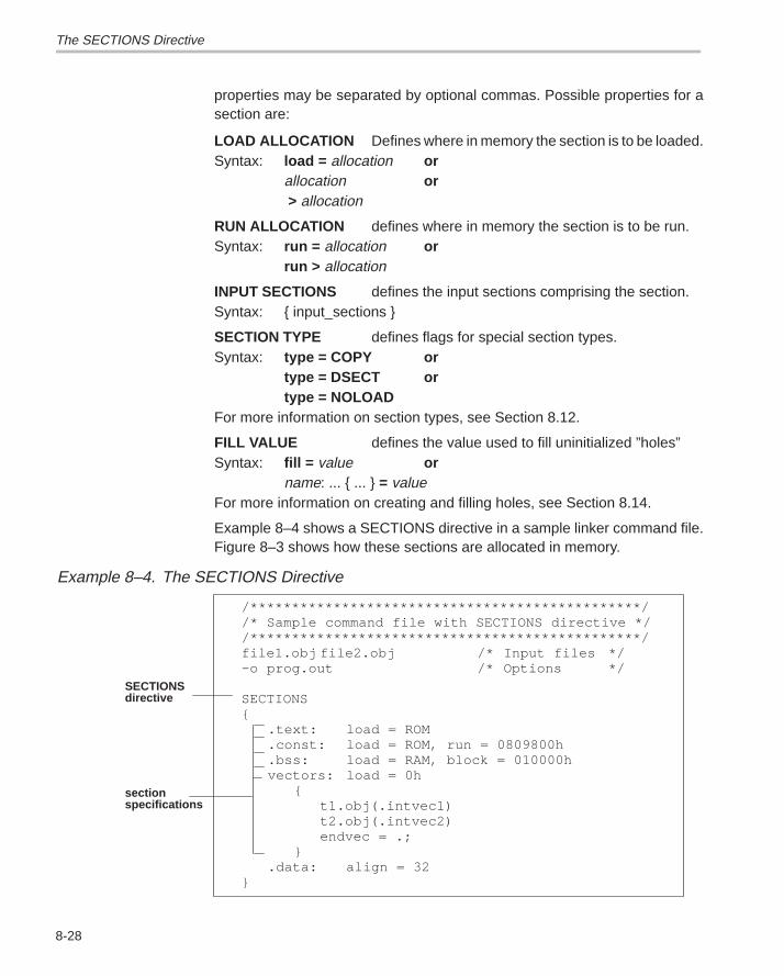
The SECTIONS Directive
8-28
properties may be separated by optional commas. Possible properties for asection are:
LOAD ALLOCATION Defines where in memory the section is to be loaded.Syntax: load = allocation or
allocation or > allocation
RUN ALLOCATION defines where in memory the section is to be run.Syntax: run = allocation or
run > allocation
INPUT SECTIONS defines the input sections comprising the section.Syntax: { input_sections }
SECTION TYPE defines flags for special section types.Syntax: type = COPY or
type = DSECT ortype = NOLOAD
For more information on section types, see Section 8.12.
FILL VALUE defines the value used to fill uninitialized ”holes”Syntax: fill = value or
name: ... { ... } = valueFor more information on creating and filling holes, see Section 8.14.
Example 8–4 shows a SECTIONS directive in a sample linker command file.Figure 8–3 shows how these sections are allocated in memory.
Example 8–4. The SECTIONS Directive
/***********************************************//* Sample command file with SECTIONS directive *//***********************************************/file1.obj file2.obj /* Input files */–o prog.out /* Options */
SECTIONS{
.text: load = ROM
.const: load = ROM, run = 0809800h
.bss: load = RAM, block = 010000hvectors: load = 0h
{t1.obj(.intvec1)t2.obj(.intvec2)endvec = .;
}.data: align = 32
}
SECTIONSdirective
sectionspecifications
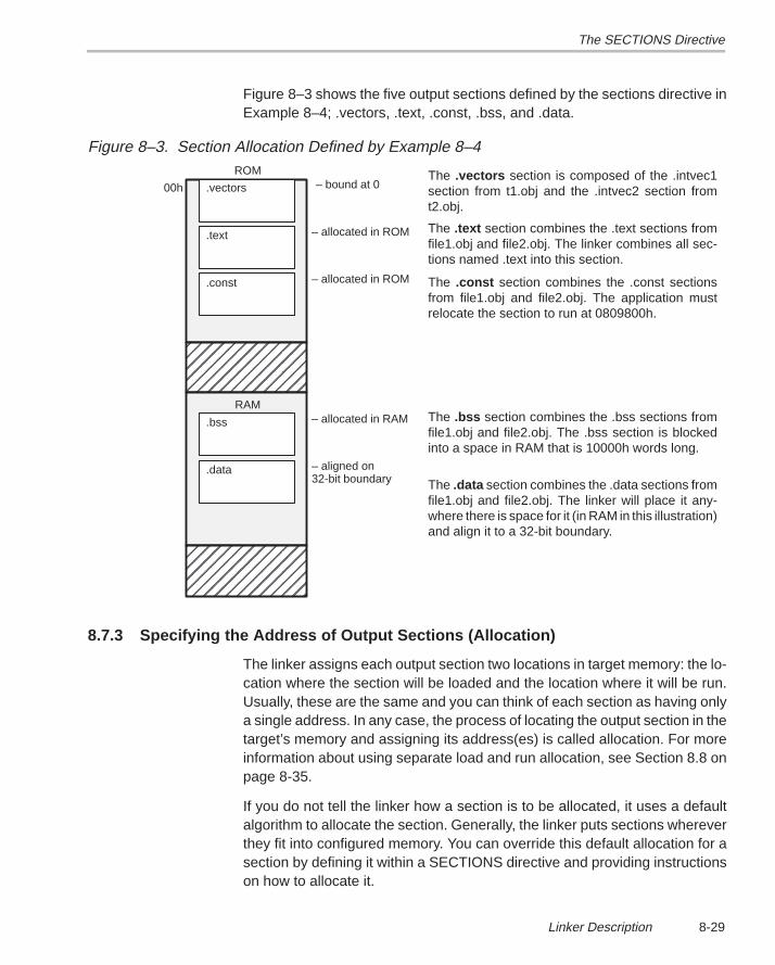
The SECTIONS Directive
8-29Linker Description
Figure 8–3 shows the five output sections defined by the sections directive inExample 8–4; .vectors, .text, .const, .bss, and .data.
Figure 8–3. Section Allocation Defined by Example 8–4
ÉÉÉÉÉÉÉÉÉÉÉÉÉÉÉÉÉÉÉÉÉ
ROM
RAM
.vectors
.text
ÉÉÉÉÉÉÉÉÉÉÉÉÉÉÉÉÉÉÉÉÉÉÉÉÉÉÉÉ
– bound at 0
– allocated in ROM
.const – allocated in ROM
.bss – allocated in RAM
.data – aligned on 32-bit boundary
00h
The .text section combines the .text sections fromfile1.obj and file2.obj. The linker combines all sec-tions named .text into this section.
The .const section combines the .const sectionsfrom file1.obj and file2.obj. The application mustrelocate the section to run at 0809800h.
The .bss section combines the .bss sections fromfile1.obj and file2.obj. The .bss section is blockedinto a space in RAM that is 10000h words long.
The .vectors section is composed of the .intvec1section from t1.obj and the .intvec2 section fromt2.obj.
The .data section combines the .data sections fromfile1.obj and file2.obj. The linker will place it any-where there is space for it (in RAM in this illustration)and align it to a 32-bit boundary.
8.7.3 Specifying the Address of Output Sections (Allocation)
The linker assigns each output section two locations in target memory: the lo-cation where the section will be loaded and the location where it will be run.Usually, these are the same and you can think of each section as having onlya single address. In any case, the process of locating the output section in thetarget’s memory and assigning its address(es) is called allocation. For moreinformation about using separate load and run allocation, see Section 8.8 onpage 8-35.
If you do not tell the linker how a section is to be allocated, it uses a defaultalgorithm to allocate the section. Generally, the linker puts sections whereverthey fit into configured memory. You can override this default allocation for asection by defining it within a SECTIONS directive and providing instructionson how to allocate it.
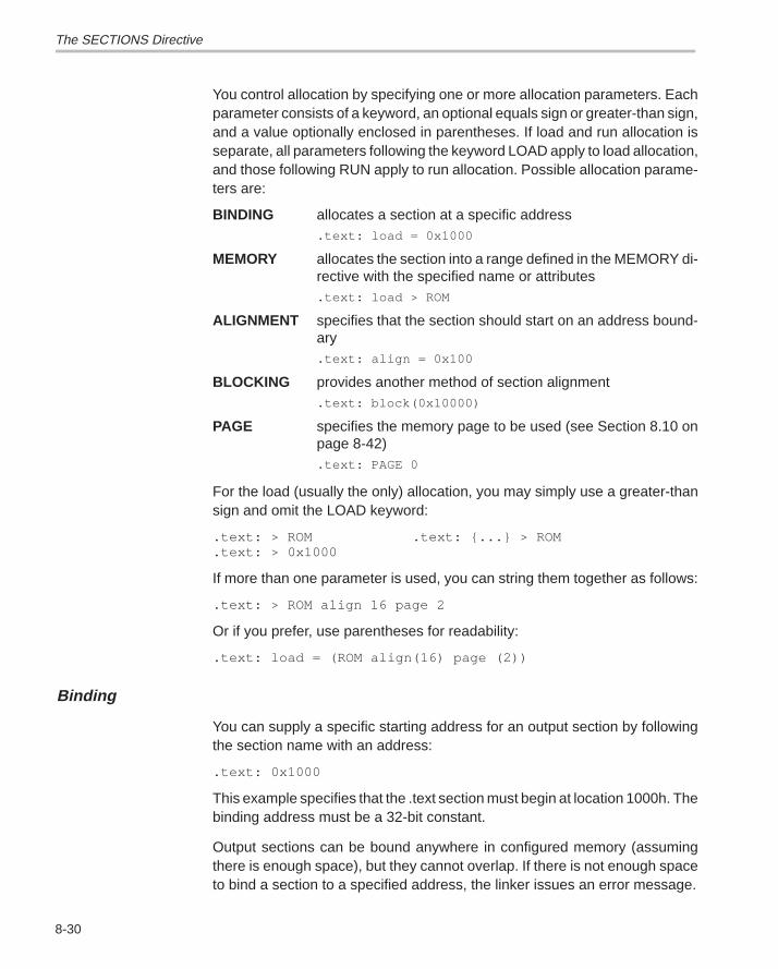
The SECTIONS Directive
8-30
You control allocation by specifying one or more allocation parameters. Eachparameter consists of a keyword, an optional equals sign or greater-than sign,and a value optionally enclosed in parentheses. If load and run allocation isseparate, all parameters following the keyword LOAD apply to load allocation,and those following RUN apply to run allocation. Possible allocation parame-ters are:
BINDING allocates a section at a specific address.text: load = 0x1000
MEMORY allocates the section into a range defined in the MEMORY di-rective with the specified name or attributes.text: load > ROM
ALIGNMENT specifies that the section should start on an address bound-ary.text: align = 0x100
BLOCKING provides another method of section alignment.text: block(0x10000)
PAGE specifies the memory page to be used (see Section 8.10 onpage 8-42).text: PAGE 0
For the load (usually the only) allocation, you may simply use a greater-thansign and omit the LOAD keyword:
.text: > ROM .text: {...} > ROM
.text: > 0x1000
If more than one parameter is used, you can string them together as follows:
.text: > ROM align 16 page 2
Or if you prefer, use parentheses for readability:
.text: load = (ROM align(16) page (2))
Binding
You can supply a specific starting address for an output section by followingthe section name with an address:
.text: 0x1000
This example specifies that the .text section must begin at location 1000h. Thebinding address must be a 32-bit constant.
Output sections can be bound anywhere in configured memory (assumingthere is enough space), but they cannot overlap. If there is not enough spaceto bind a section to a specified address, the linker issues an error message.
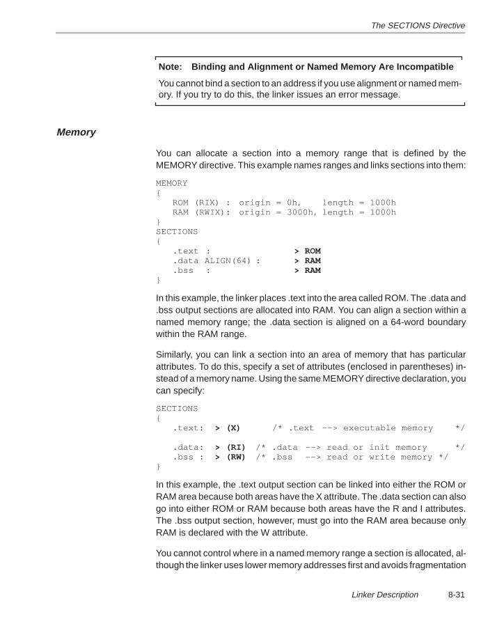
The SECTIONS Directive
8-31Linker Description
Note: Binding and Alignment or Named Memory Are Incompatible
You cannot bind a section to an address if you use alignment or named mem-ory. If you try to do this, the linker issues an error message.
Memory
You can allocate a section into a memory range that is defined by theMEMORY directive. This example names ranges and links sections into them:
MEMORY{
ROM (RIX) : origin = 0h, length = 1000h RAM (RWIX): origin = 3000h, length = 1000h
} SECTIONS{
.text : > ROM
.data ALIGN(64) : > RAM
.bss : > RAM}
In this example, the linker places .text into the area called ROM. The .data and.bss output sections are allocated into RAM. You can align a section within anamed memory range; the .data section is aligned on a 64-word boundarywithin the RAM range.
Similarly, you can link a section into an area of memory that has particularattributes. To do this, specify a set of attributes (enclosed in parentheses) in-stead of a memory name. Using the same MEMORY directive declaration, youcan specify:
SECTIONS{
.text: > (X) /* .text ––> executable memory */
.data: > (RI) /* .data ––> read or init memory */
.bss : > (RW) /* .bss ––> read or write memory */}
In this example, the .text output section can be linked into either the ROM orRAM area because both areas have the X attribute. The .data section can alsogo into either ROM or RAM because both areas have the R and I attributes.The .bss output section, however, must go into the RAM area because onlyRAM is declared with the W attribute.
You cannot control where in a named memory range a section is allocated, al-though the linker uses lower memory addresses first and avoids fragmentation
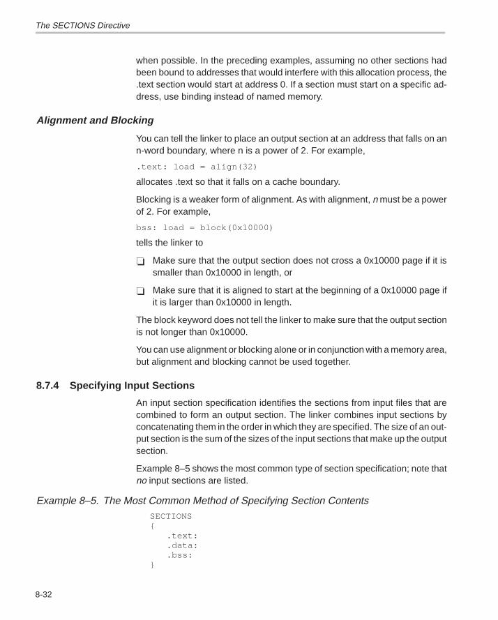
The SECTIONS Directive
8-32
when possible. In the preceding examples, assuming no other sections hadbeen bound to addresses that would interfere with this allocation process, the.text section would start at address 0. If a section must start on a specific ad-dress, use binding instead of named memory.
Alignment and Blocking
You can tell the linker to place an output section at an address that falls on ann-word boundary, where n is a power of 2. For example,
.text: load = align(32)
allocates .text so that it falls on a cache boundary.
Blocking is a weaker form of alignment. As with alignment, n must be a powerof 2. For example,
bss: load = block(0x10000)
tells the linker to
� Make sure that the output section does not cross a 0x10000 page if it issmaller than 0x10000 in length, or
� Make sure that it is aligned to start at the beginning of a 0x10000 page ifit is larger than 0x10000 in length.
The block keyword does not tell the linker to make sure that the output sectionis not longer than 0x10000.
You can use alignment or blocking alone or in conjunction with a memory area,but alignment and blocking cannot be used together.
8.7.4 Specifying Input Sections
An input section specification identifies the sections from input files that arecombined to form an output section. The linker combines input sections byconcatenating them in the order in which they are specified. The size of an out-put section is the sum of the sizes of the input sections that make up the outputsection.
Example 8–5 shows the most common type of section specification; note thatno input sections are listed.
Example 8–5. The Most Common Method of Specifying Section ContentsSECTIONS{
.text:
.data:
.bss:}
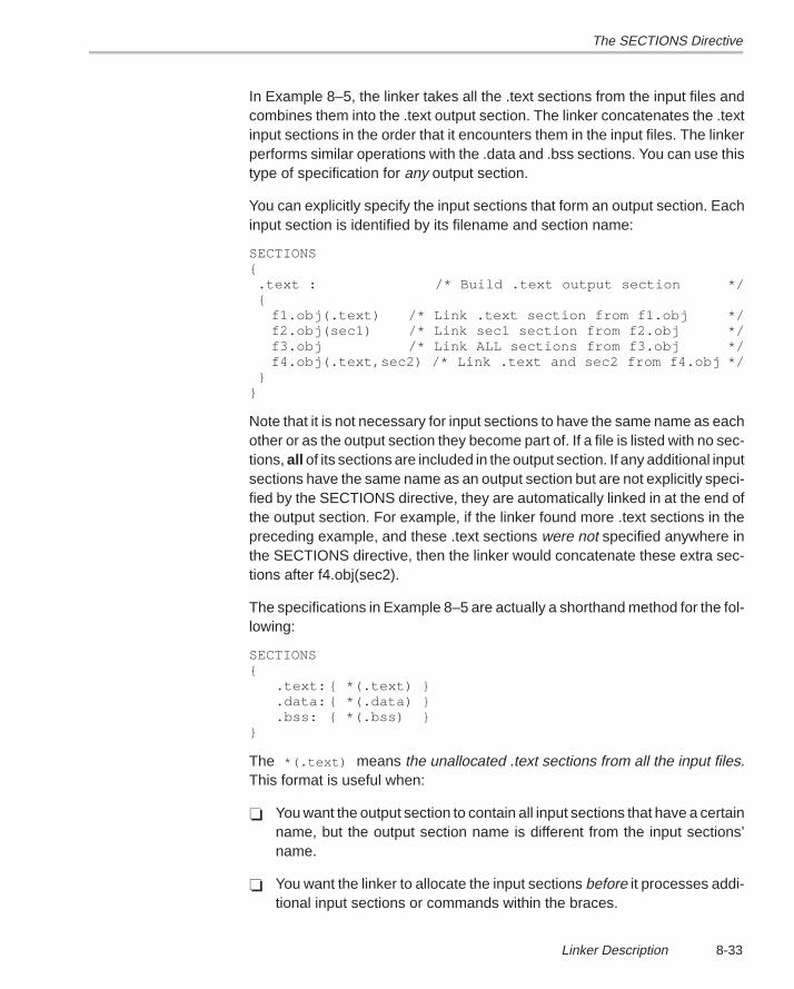
The SECTIONS Directive
8-33Linker Description
In Example 8–5, the linker takes all the .text sections from the input files andcombines them into the .text output section. The linker concatenates the .textinput sections in the order that it encounters them in the input files. The linkerperforms similar operations with the .data and .bss sections. You can use thistype of specification for any output section.
You can explicitly specify the input sections that form an output section. Eachinput section is identified by its filename and section name:
SECTIONS{ .text : /* Build .text output section */ {
f1.obj(.text) /* Link .text section from f1.obj */f2.obj(sec1) /* Link sec1 section from f2.obj */f3.obj /* Link ALL sections from f3.obj */f4.obj(.text,sec2) /* Link .text and sec2 from f4.obj */
}}
Note that it is not necessary for input sections to have the same name as eachother or as the output section they become part of. If a file is listed with no sec-tions, all of its sections are included in the output section. If any additional inputsections have the same name as an output section but are not explicitly speci-fied by the SECTIONS directive, they are automatically linked in at the end ofthe output section. For example, if the linker found more .text sections in thepreceding example, and these .text sections were not specified anywhere inthe SECTIONS directive, then the linker would concatenate these extra sec-tions after f4.obj(sec2).
The specifications in Example 8–5 are actually a shorthand method for the fol-lowing:
SECTIONS{
.text: { *(.text) }
.data: { *(.data) }
.bss: { *(.bss) }}
The *(.text) means the unallocated .text sections from all the input files.This format is useful when:
� You want the output section to contain all input sections that have a certainname, but the output section name is different from the input sections’name.
� You want the linker to allocate the input sections before it processes addi-tional input sections or commands within the braces.
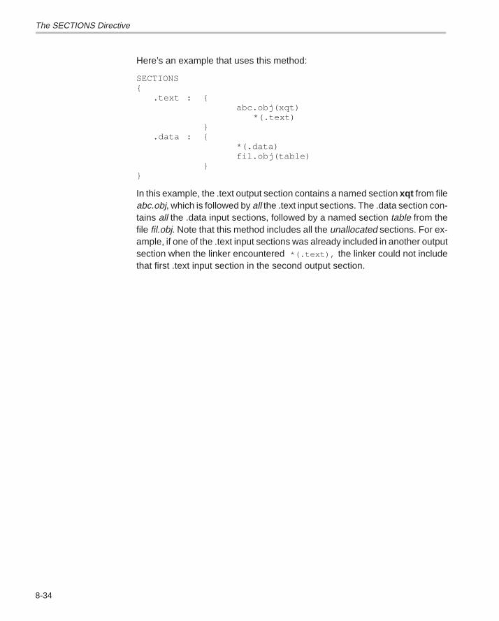
The SECTIONS Directive
8-34
Here’s an example that uses this method:
SECTIONS{
.text : {abc.obj(xqt)
*(.text)}
.data : {*(.data)fil.obj(table)
}}
In this example, the .text output section contains a named section xqt from fileabc.obj, which is followed by all the .text input sections. The .data section con-tains all the .data input sections, followed by a named section table from thefile fil.obj. Note that this method includes all the unallocated sections. For ex-ample, if one of the .text input sections was already included in another outputsection when the linker encountered *(.text) , the linker could not includethat first .text input section in the second output section.
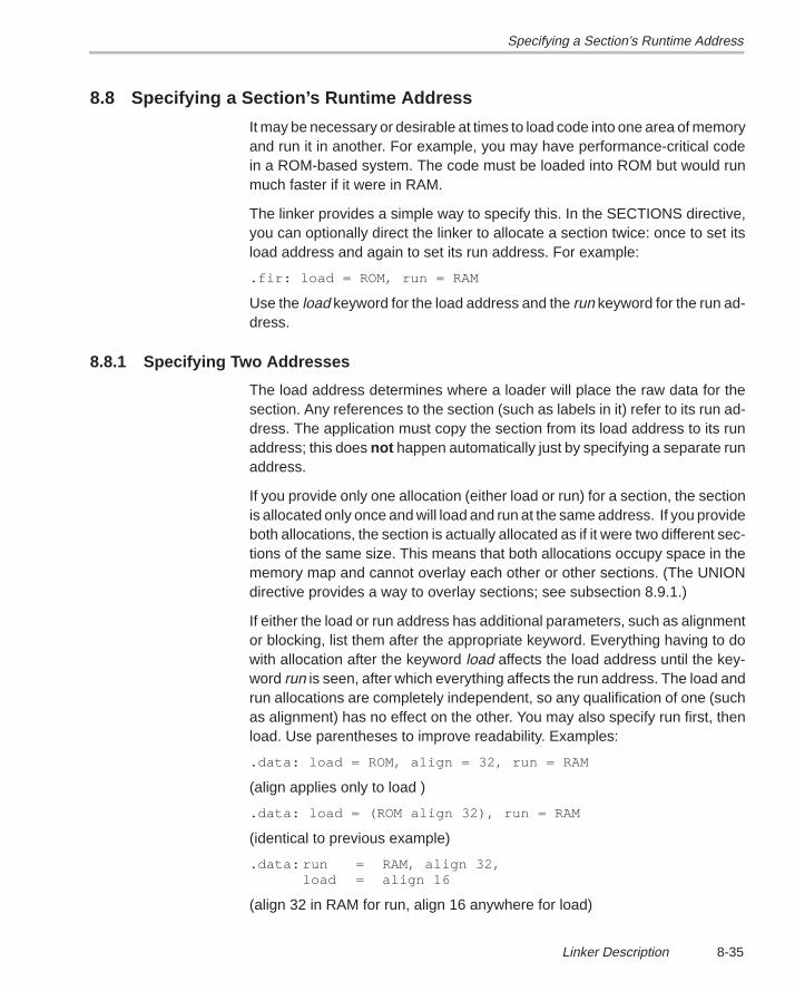
Specifying a Section’s Runtime Address
8-35Linker Description
8.8 Specifying a Section’s Runtime Address
It may be necessary or desirable at times to load code into one area of memoryand run it in another. For example, you may have performance-critical codein a ROM-based system. The code must be loaded into ROM but would runmuch faster if it were in RAM.
The linker provides a simple way to specify this. In the SECTIONS directive,you can optionally direct the linker to allocate a section twice: once to set itsload address and again to set its run address. For example:
.fir: load = ROM, run = RAM
Use the load keyword for the load address and the run keyword for the run ad-dress.
8.8.1 Specifying Two Addresses
The load address determines where a loader will place the raw data for thesection. Any references to the section (such as labels in it) refer to its run ad-dress. The application must copy the section from its load address to its runaddress; this does not happen automatically just by specifying a separate runaddress.
If you provide only one allocation (either load or run) for a section, the sectionis allocated only once and will load and run at the same address. If you provideboth allocations, the section is actually allocated as if it were two different sec-tions of the same size. This means that both allocations occupy space in thememory map and cannot overlay each other or other sections. (The UNIONdirective provides a way to overlay sections; see subsection 8.9.1.)
If either the load or run address has additional parameters, such as alignmentor blocking, list them after the appropriate keyword. Everything having to dowith allocation after the keyword load affects the load address until the key-word run is seen, after which everything affects the run address. The load andrun allocations are completely independent, so any qualification of one (suchas alignment) has no effect on the other. You may also specify run first, thenload. Use parentheses to improve readability. Examples:
.data: load = ROM, align = 32, run = RAM
(align applies only to load )
.data: load = (ROM align 32), run = RAM
(identical to previous example)
.data: run = RAM, align 32,load = align 16
(align 32 in RAM for run, align 16 anywhere for load)
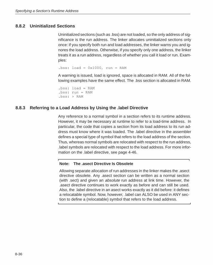
Specifying a Section’s Runtime Address
8-36
8.8.2 Uninitialized Sections
Uninitialized sections (such as .bss) are not loaded, so the only address of sig-nificance is the run address. The linker allocates uninitialized sections onlyonce: if you specify both run and load addresses, the linker warns you and ig-nores the load address. Otherwise, if you specify only one address, the linkertreats it as a run address, regardless of whether you call it load or run. Exam-ples:
.bss: load = 0x1000, run = RAM
A warning is issued, load is ignored, space is allocated in RAM. All of the fol-lowing examples have the same effect. The .bss section is allocated in RAM.
.bss: load = RAM
.bss: run = RAM
.bss: > RAM
8.8.3 Referring to a Load Address by Using the .label Directive
Any reference to a normal symbol in a section refers to its runtime address.However, it may be necessary at runtime to refer to a load-time address. Inparticular, the code that copies a section from its load address to its run ad-dress must know where it was loaded. The .label directive in the assemblerdefines a special type of symbol that refers to the load address of the section.Thus, whereas normal symbols are relocated with respect to the run address,.label symbols are relocated with respect to the load address. For more infor-mation on the .label directive, see page 4-46.
Note: The .asect Directive Is Obsolete
Allowing separate allocation of run addresses in the linker makes the .asectdirective obsolete. Any .asect section can be written as a normal section(with .sect) and given an absolute run address at link time. However, the.asect directive continues to work exactly as before and can still be used.Also, the .label directive in an asect works exactly as it did before: it definesa relocatable symbol. Now, however, .label can ALSO be used in ANY sec-tion to define a (relocatable) symbol that refers to the load address.
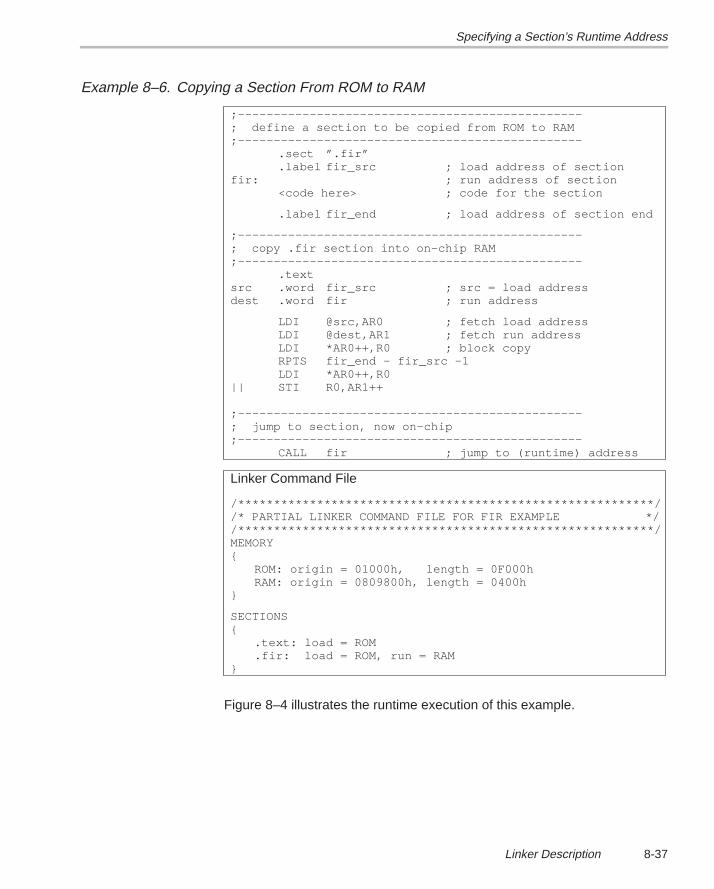
Specifying a Section’s Runtime Address
8-37Linker Description
Example 8–6. Copying a Section From ROM to RAM
;––––––––––––––––––––––––––––––––––––––––––––––––; define a section to be copied from ROM to RAM;––––––––––––––––––––––––––––––––––––––––––––––––
.sect ”.fir”
.label fir_src ; load address of sectionfir: ; run address of section
<code here> ; code for the section
.label fir_end ; load address of section end
;––––––––––––––––––––––––––––––––––––––––––––––––; copy .fir section into on–chip RAM;––––––––––––––––––––––––––––––––––––––––––––––––
.textsrc .word fir_src ; src = load addressdest .word fir ; run address
LDI @src,AR0 ; fetch load addressLDI @dest,AR1 ; fetch run addressLDI *AR0++,R0 ; block copyRPTS fir_end – fir_src –1LDI *AR0++,R0
|| STI R0,AR1++ ;––––––––––––––––––––––––––––––––––––––––––––––––; jump to section, now on–chip;––––––––––––––––––––––––––––––––––––––––––––––––
CALL fir ; jump to (runtime) address
Linker Command File
/**********************************************************//* PARTIAL LINKER COMMAND FILE FOR FIR EXAMPLE *//**********************************************************/MEMORY{
ROM: origin = 01000h, length = 0F000hRAM: origin = 0809800h, length = 0400h
}
SECTIONS{
.text: load = ROM
.fir: load = ROM, run = RAM}
Figure 8–4 illustrates the runtime execution of this example.
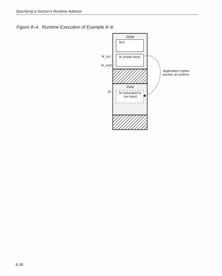
Specifying a Section’s Runtime Address
8-38
Figure 8–4. Runtime Execution of Example 8–6
ÉÉÉÉÉÉÉÉÉÉÉÉÉÉÉÉÉÉ
ROM
RAM
Application copiessection at runtime
fir_src:
fir_end:
fir: .fir (relocated torun here)
.text
.fir (loads here)
ÉÉÉÉÉÉÉÉÉÉÉÉÉÉÉÉÉÉ
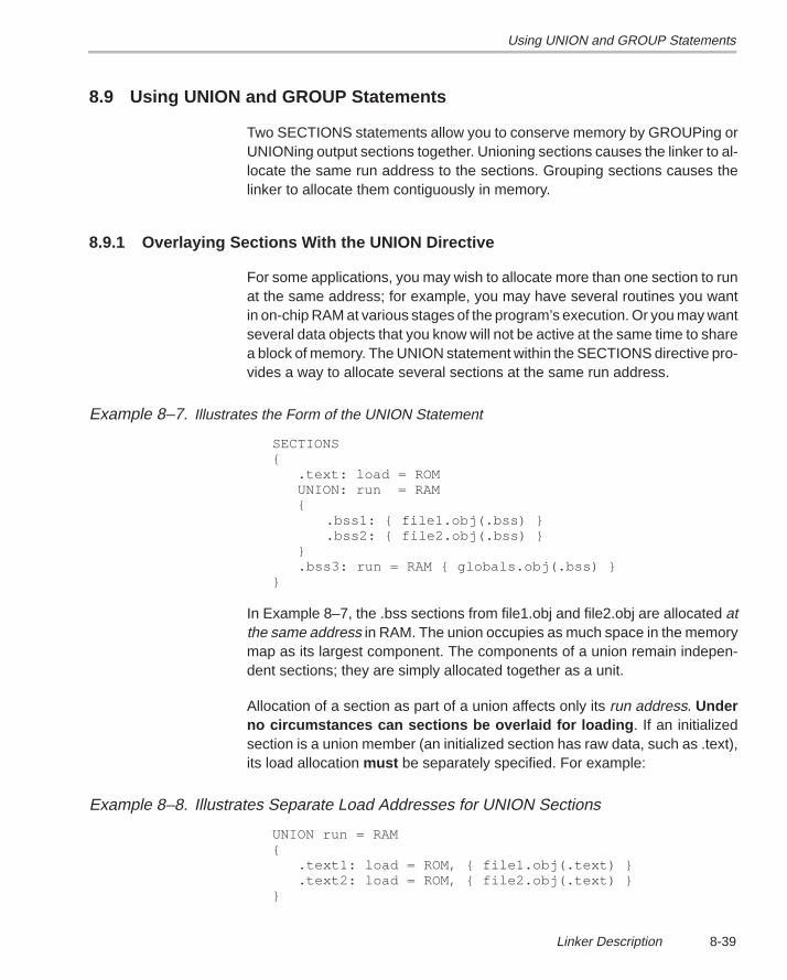
Using UNION and GROUP Statements
8-39Linker Description
8.9 Using UNION and GROUP Statements
Two SECTIONS statements allow you to conserve memory by GROUPing orUNIONing output sections together. Unioning sections causes the linker to al-locate the same run address to the sections. Grouping sections causes thelinker to allocate them contiguously in memory.
8.9.1 Overlaying Sections With the UNION Directive
For some applications, you may wish to allocate more than one section to runat the same address; for example, you may have several routines you wantin on-chip RAM at various stages of the program’s execution. Or you may wantseveral data objects that you know will not be active at the same time to sharea block of memory. The UNION statement within the SECTIONS directive pro-vides a way to allocate several sections at the same run address.
Example 8–7. Illustrates the Form of the UNION Statement
SECTIONS { .text: load = ROM UNION: run = RAM {
.bss1: { file1.obj(.bss) }
.bss2: { file2.obj(.bss) } } .bss3: run = RAM { globals.obj(.bss) } }
In Example 8–7, the .bss sections from file1.obj and file2.obj are allocated atthe same address in RAM. The union occupies as much space in the memorymap as its largest component. The components of a union remain indepen-dent sections; they are simply allocated together as a unit.
Allocation of a section as part of a union affects only its run address. Underno circumstances can sections be overlaid for loading . If an initializedsection is a union member (an initialized section has raw data, such as .text),its load allocation must be separately specified. For example:
Example 8–8. Illustrates Separate Load Addresses for UNION Sections
UNION run = RAM { .text1: load = ROM, { file1.obj(.text) } .text2: load = ROM, { file2.obj(.text) } }
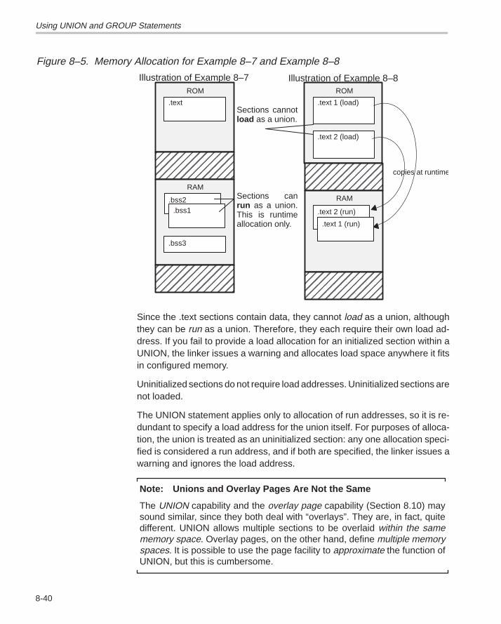
Using UNION and GROUP Statements
8-40
Figure 8–5. Memory Allocation for Example 8–7 and Example 8–8
ÉÉÉÉÉÉÉÉÉÉÉÉÉÉÉÉÉÉ
ÉÉÉÉÉÉÉÉÉÉÉÉÉÉÉÉÉÉ
ROM
RAM
.text 2 (run)
.text 1 (load)
.text 1 (run)
.text 2 (load)
copies at runtime
ÉÉÉÉÉÉÉÉÉÉÉÉÉÉÉÉÉÉ
ÉÉÉÉÉÉÉÉÉÉÉÉÉÉÉÉÉÉ
ROM
RAM
.text
.bss2.bss1
.bss3
Illustration of Example 8–7 Illustration of Example 8–8
Sections cannotload as a union.
Sections canrun as a union.This is runtimeallocation only.
Since the .text sections contain data, they cannot load as a union, althoughthey can be run as a union. Therefore, they each require their own load ad-dress. If you fail to provide a load allocation for an initialized section within aUNION, the linker issues a warning and allocates load space anywhere it fitsin configured memory.
Uninitialized sections do not require load addresses. Uninitialized sections arenot loaded.
The UNION statement applies only to allocation of run addresses, so it is re-dundant to specify a load address for the union itself. For purposes of alloca-tion, the union is treated as an uninitialized section: any one allocation speci-fied is considered a run address, and if both are specified, the linker issues awarning and ignores the load address.
Note: Unions and Overlay Pages Are Not the Same
The UNION capability and the overlay page capability (Section 8.10) maysound similar, since they both deal with “overlays”. They are, in fact, quitedifferent. UNION allows multiple sections to be overlaid within the samememory space. Overlay pages, on the other hand, define multiple memoryspaces. It is possible to use the page facility to approximate the function ofUNION, but this is cumbersome.
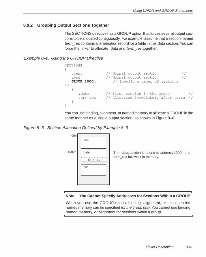
Using UNION and GROUP Statements
8-41Linker Description
8.9.2 Grouping Output Sections Together
The SECTIONS directive has a GROUP option that forces several output sec-tions to be allocated contiguously. For example, assume that a section namedterm_rec contains a termination record for a table in the .data section. You canforce the linker to allocate .data and term_rec together:
Example 8–9. Using the GROUP Directive
SECTIONS{
.text /* Normal output section */
.bss /* Normal output section */GROUP 1000h : /* Specify a group of sections
*/{
.data /* First section in the group */term_rec /* Allocated immediately after .data */
}}
You can use binding, alignment, or named memory to allocate a GROUP in thesame manner as a single output section, as shown in Figure 8–6.
Figure 8–6. Section Allocation Defined by Example 8–9
.text
.bss
.data
00h
term_rec
The .data section is bound to address 1000h andterm_rec follows it in memory.
1000h
Note: You Cannot Specify Addresses for Sections Within a GROUP
When you use the GROUP option, binding, alignment, or allocation intonamed memory can be specified for the group only. You cannot use binding,named memory, or alignment for sections within a group.
Overlay Pages
8-42
8.10 Overlay Pages
Some target systems use an overlay memory configuration in which all or partof the memory space is overlaid by shadow memory. This allows the systemto map different banks of physical memory in and out of a single address rangein response to hardware selection signals. In this situation, multiple areas ofphysical memory overlay each other at one address. You may want the linkerto load various output sections into each of these areas or into areas that arenot mapped at loadtime.
The linker supports this feature by providing overlay pages. Overlay pagesallow you to define a memory model that has multiple address spaces. To thelinker, each possible overlay configuration represents a separate addressspace. Each address range is treated as a separate page and must be confi-gured separately with the MEMORY directive. You can then use theSECTIONS directive to specify which sections will be mapped into variouspages.
8.10.1 Using the MEMORY Directive to Define Overlay Pages
Each separately configured address space is called a page. To the linker, eachpage represents a completely separate memory that has the full 32-bit rangeof addressable locations. This allows you to link two or more sections at thesame (or overlapping) addresses if they are on different pages.
Pages are numbered sequentially, beginning with 0. Page 0 represents thenormal address space of the TMS320C3x/C4x. The default memory model re-sides entirely on page 0. If a memory range is specified without a page number,the linker assumes it is in page 0. This allows you to ignore the page featurefor most cases; usually, all sections can be linked in page 0 with no overlays.
For example, assume that your system can select among three 4K-word longbanks of physical memory to map into the address space from 1000h to 2000h.Although only one bank can be selected at a time, you can initialize each bankwith different data. Assume you have three output sections called sect0, sect1,and sect2 that must be linked into the three banks of memory. This is how youwould use the MEMORY directive to obtain this configuration:
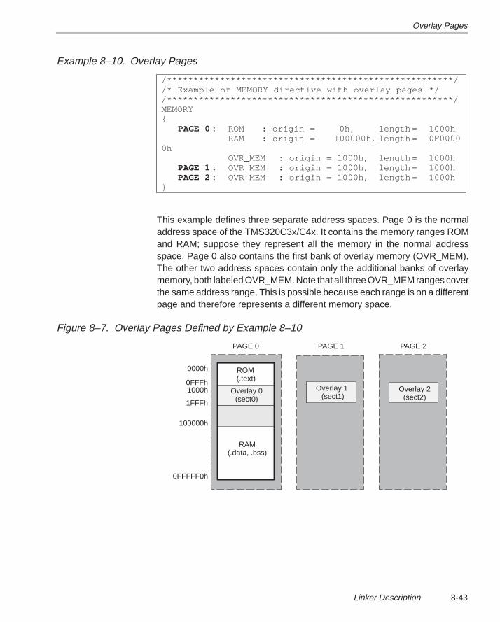
Overlay Pages
8-43Linker Description
Example 8–10. Overlay Pages
/******************************************************//* Example of MEMORY directive with overlay pages *//******************************************************/MEMORY{
PAGE 0 : ROM : origin = 0h, length = 1000hRAM : origin = 100000h, length = 0F0000
0hOVR_MEM : origin = 1000h, length = 1000h
PAGE 1 : OVR_MEM : origin = 1000h, length = 1000hPAGE 2 : OVR_MEM : origin = 1000h, length = 1000h
}
This example defines three separate address spaces. Page 0 is the normaladdress space of the TMS320C3x/C4x. It contains the memory ranges ROMand RAM; suppose they represent all the memory in the normal addressspace. Page 0 also contains the first bank of overlay memory (OVR_MEM).The other two address spaces contain only the additional banks of overlaymemory, both labeled OVR_MEM. Note that all three OVR_MEM ranges coverthe same address range. This is possible because each range is on a differentpage and therefore represents a different memory space.
Figure 8–7. Overlay Pages Defined by Example 8–10
Overlay 0(sect0)
ROM (.text)
RAM(.data, .bss)
0000h
0FFFh1000h
1FFFh
100000h
0FFFFF0h
PAGE 0 PAGE 1 PAGE 2
Overlay 1 (sect1)
Overlay 2(sect2)
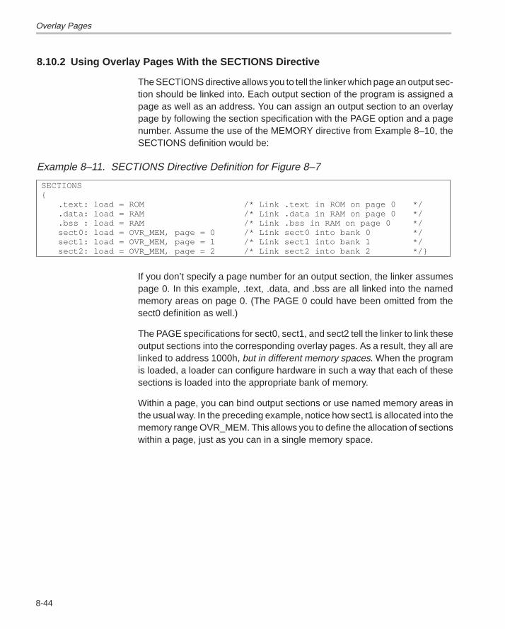
Overlay Pages
8-44
8.10.2 Using Overlay Pages With the SECTIONS Directive
The SECTIONS directive allows you to tell the linker which page an output sec-tion should be linked into. Each output section of the program is assigned apage as well as an address. You can assign an output section to an overlaypage by following the section specification with the PAGE option and a pagenumber. Assume the use of the MEMORY directive from Example 8–10, theSECTIONS definition would be:
Example 8–11. SECTIONS Directive Definition for Figure 8–7
SECTIONS{
.text: load = ROM /* Link .text in ROM on page 0 */
.data: load = RAM /* Link .data in RAM on page 0 */
.bss : load = RAM /* Link .bss in RAM on page 0 */sect0: load = OVR_MEM, page = 0 /* Link sect0 into bank 0 */sect1: load = OVR_MEM, page = 1 /* Link sect1 into bank 1 */sect2: load = OVR_MEM, page = 2 /* Link sect2 into bank 2 */}
If you don’t specify a page number for an output section, the linker assumespage 0. In this example, .text, .data, and .bss are all linked into the namedmemory areas on page 0. (The PAGE 0 could have been omitted from thesect0 definition as well.)
The PAGE specifications for sect0, sect1, and sect2 tell the linker to link theseoutput sections into the corresponding overlay pages. As a result, they all arelinked to address 1000h, but in different memory spaces. When the programis loaded, a loader can configure hardware in such a way that each of thesesections is loaded into the appropriate bank of memory.
Within a page, you can bind output sections or use named memory areas inthe usual way. In the preceding example, notice how sect1 is allocated into thememory range OVR_MEM. This allows you to define the allocation of sectionswithin a page, just as you can in a single memory space.
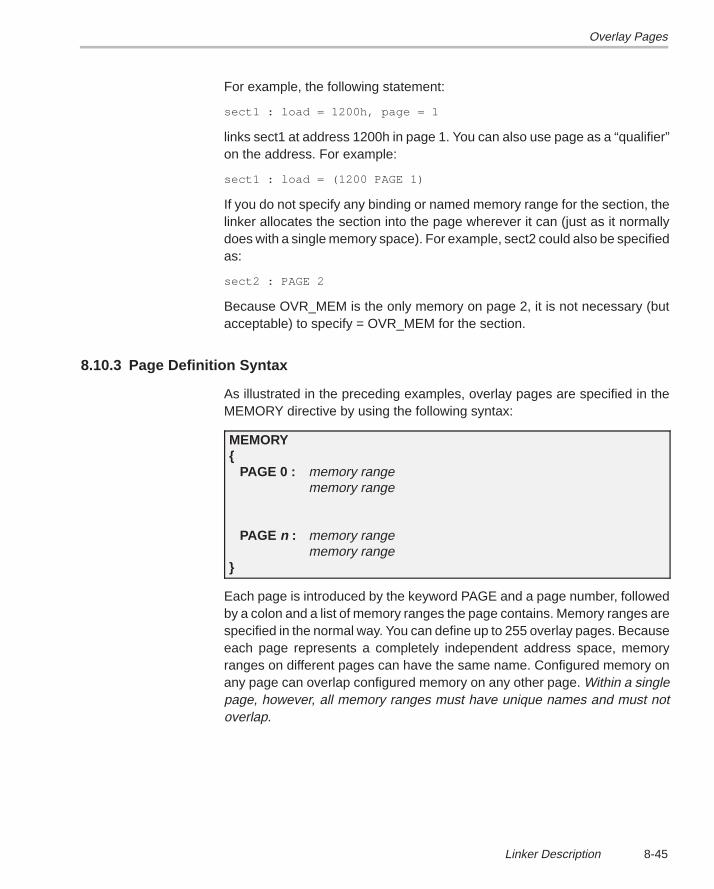
Overlay Pages
8-45Linker Description
For example, the following statement:
sect1 : load = 1200h, page = 1
links sect1 at address 1200h in page 1. You can also use page as a “qualifier”on the address. For example:
sect1 : load = (1200 PAGE 1)
If you do not specify any binding or named memory range for the section, thelinker allocates the section into the page wherever it can (just as it normallydoes with a single memory space). For example, sect2 could also be specifiedas:
sect2 : PAGE 2
Because OVR_MEM is the only memory on page 2, it is not necessary (butacceptable) to specify = OVR_MEM for the section.
8.10.3 Page Definition Syntax
As illustrated in the preceding examples, overlay pages are specified in theMEMORY directive by using the following syntax:
MEMORY{
PAGE 0 : memory rangememory range
PAGE n : memory rangememory range
}
Each page is introduced by the keyword PAGE and a page number, followedby a colon and a list of memory ranges the page contains. Memory ranges arespecified in the normal way. You can define up to 255 overlay pages. Becauseeach page represents a completely independent address space, memoryranges on different pages can have the same name. Configured memory onany page can overlap configured memory on any other page. Within a singlepage, however, all memory ranges must have unique names and must notoverlap.
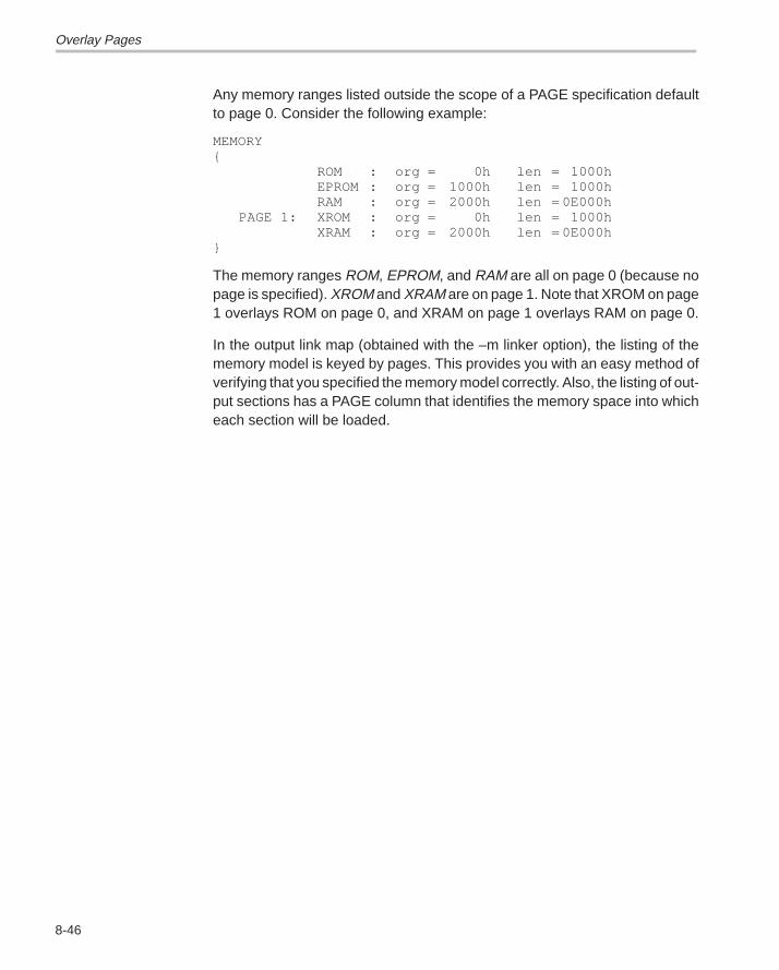
Overlay Pages
8-46
Any memory ranges listed outside the scope of a PAGE specification defaultto page 0. Consider the following example:
MEMORY{
ROM : org = 0h len = 1000hEPROM : org = 1000h len = 1000hRAM : org = 2000h len = 0E000h
PAGE 1: XROM : org = 0h len = 1000hXRAM : org = 2000h len = 0E000h
}
The memory ranges ROM, EPROM, and RAM are all on page 0 (because nopage is specified). XROM and XRAM are on page 1. Note that XROM on page1 overlays ROM on page 0, and XRAM on page 1 overlays RAM on page 0.
In the output link map (obtained with the –m linker option), the listing of thememory model is keyed by pages. This provides you with an easy method ofverifying that you specified the memory model correctly. Also, the listing of out-put sections has a PAGE column that identifies the memory space into whicheach section will be loaded.
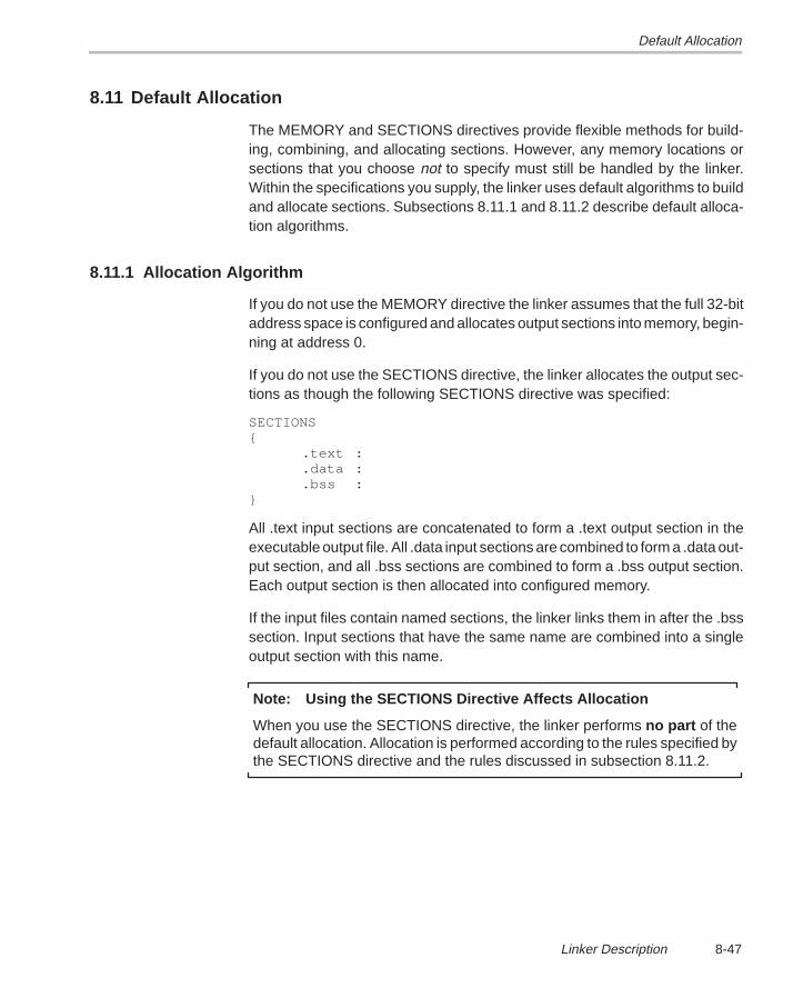
Default Allocation
8-47Linker Description
8.11 Default Allocation
The MEMORY and SECTIONS directives provide flexible methods for build-ing, combining, and allocating sections. However, any memory locations orsections that you choose not to specify must still be handled by the linker.Within the specifications you supply, the linker uses default algorithms to buildand allocate sections. Subsections 8.11.1 and 8.11.2 describe default alloca-tion algorithms.
8.11.1 Allocation Algorithm
If you do not use the MEMORY directive the linker assumes that the full 32-bitaddress space is configured and allocates output sections into memory, begin-ning at address 0.
If you do not use the SECTIONS directive, the linker allocates the output sec-tions as though the following SECTIONS directive was specified:
SECTIONS{
.text :
.data :
.bss :}
All .text input sections are concatenated to form a .text output section in theexecutable output file. All .data input sections are combined to form a .data out-put section, and all .bss sections are combined to form a .bss output section.Each output section is then allocated into configured memory.
If the input files contain named sections, the linker links them in after the .bsssection. Input sections that have the same name are combined into a singleoutput section with this name.
Note: Using the SECTIONS Directive Affects Allocation
When you use the SECTIONS directive, the linker performs no part of thedefault allocation. Allocation is performed according to the rules specified bythe SECTIONS directive and the rules discussed in subsection 8.11.2.
Default Allocation
8-48
8.11.2 General Rules for Output Sections
An output section can be formed in one of two ways:
Rule 1 As the result of a SECTIONS directive definition.
Rule 2 By combining input sections with the same names into output sec-tions that are not defined in a SECTIONS directive.
If an output section is formed as a result of a SECTIONS directive (rule 1), thisdefinition completely determines its contents. (See Section 8.7, page 8-27, forexamples of how to specify the contents of output sections.)
An output section can also be formed when input sections are encounteredthat are not specified by any SECTIONS directive (rule 2). In this case, thelinker combines all such input sections that have the same name into an outputsection with this name. For example, suppose that the files f1.obj and f2.objboth contain named sections called Vectors and that the SECTIONS directivedoes not define an output section to contain them. The linker will combine thetwo Vectors sections from the input files into a single output section namedVectors, allocate it into memory, and include it in the output file.
After the linker determines the composition of all the output sections, it mustallocate them into configured memory. The MEMORY directive specifieswhich portions of memory are configured, or if there is no MEMORY directive,the linker uses the default configuration.
The linker’s allocation algorithm attempts to minimize memory fragmentation.This allows memory to be used more efficiently and increases the probabilitythat your program will fit into memory. This is the algorithm:
1) Any output section for which you have listed a specific binding address isplaced in memory at that address.
2) Any output section that is included in a specific named memory range orthat has memory attribute restrictions is allocated. Each output section isplaced into the first available space within the named area, consideringalignment where necessary.
3) Any remaining sections are allocated in the order in which they were de-fined. Sections not defined in a SECTIONS directive are allocated in theorder in which they were encountered. Each output section is placed intothe first available memory space, considering alignment or blocking wherenecessary.
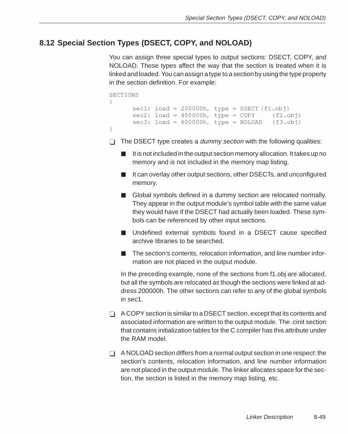
Special Section Types (DSECT, COPY, and NOLOAD)
8-49Linker Description
8.12 Special Section Types (DSECT, COPY, and NOLOAD)
You can assign three special types to output sections: DSECT, COPY, andNOLOAD. These types affect the way that the section is treated when it islinked and loaded. You can assign a type to a section by using the type propertyin the section definition. For example:
SECTIONS{
sec1: load = 200000h, type = DSECT {f1.obj}sec2: load = 400000h, type = COPY {f2.obj}sec3: load = 600000h, type = NOLOAD {f3.obj}
}
� The DSECT type creates a dummy section with the following qualities:
� It is not included in the output section memory allocation. It takes up nomemory and is not included in the memory map listing.
� It can overlay other output sections, other DSECTs, and unconfiguredmemory.
� Global symbols defined in a dummy section are relocated normally.They appear in the output module’s symbol table with the same valuethey would have if the DSECT had actually been loaded. These sym-bols can be referenced by other input sections.
� Undefined external symbols found in a DSECT cause specifiedarchive libraries to be searched.
� The section’s contents, relocation information, and line number infor-mation are not placed in the output module.
In the preceding example, none of the sections from f1.obj are allocated,but all the symbols are relocated as though the sections were linked at ad-dress 200000h. The other sections can refer to any of the global symbolsin sec1.
� A COPY section is similar to a DSECT section, except that its contents andassociated information are written to the output module. The .cinit sectionthat contains initialization tables for the C compiler has this attribute underthe RAM model.
� A NOLOAD section differs from a normal output section in one respect: thesection’s contents, relocation information, and line number informationare not placed in the output module. The linker allocates space for the sec-tion, the section is listed in the memory map listing, etc.
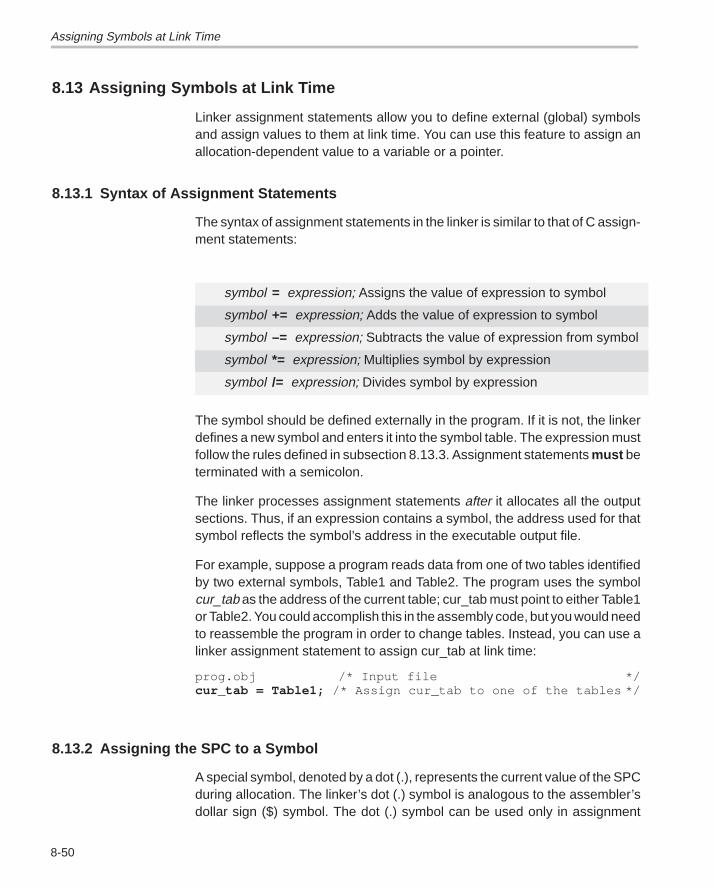
Assigning Symbols at Link Time
8-50
8.13 Assigning Symbols at Link Time
Linker assignment statements allow you to define external (global) symbolsand assign values to them at link time. You can use this feature to assign anallocation-dependent value to a variable or a pointer.
8.13.1 Syntax of Assignment Statements
The syntax of assignment statements in the linker is similar to that of C assign-ment statements:
symbol = expression; Assigns the value of expression to symbol
symbol += expression; Adds the value of expression to symbol
symbol –= expression; Subtracts the value of expression from symbol
symbol *= expression; Multiplies symbol by expression
symbol /= expression; Divides symbol by expression
The symbol should be defined externally in the program. If it is not, the linkerdefines a new symbol and enters it into the symbol table. The expression mustfollow the rules defined in subsection 8.13.3. Assignment statements must beterminated with a semicolon.
The linker processes assignment statements after it allocates all the outputsections. Thus, if an expression contains a symbol, the address used for thatsymbol reflects the symbol’s address in the executable output file.
For example, suppose a program reads data from one of two tables identifiedby two external symbols, Table1 and Table2. The program uses the symbolcur_tab as the address of the current table; cur_tab must point to either Table1or Table2. You could accomplish this in the assembly code, but you would needto reassemble the program in order to change tables. Instead, you can use alinker assignment statement to assign cur_tab at link time:
prog.obj /* Input file */cur_tab = Table1; /* Assign cur_tab to one of the tables */
8.13.2 Assigning the SPC to a Symbol
A special symbol, denoted by a dot (.), represents the current value of the SPCduring allocation. The linker’s dot (.) symbol is analogous to the assembler’sdollar sign ($) symbol. The dot (.) symbol can be used only in assignment
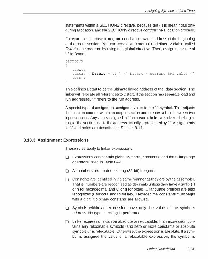
Assigning Symbols at Link Time
8-51Linker Description
statements within a SECTIONS directive, because dot (.) is meaningful onlyduring allocation, and the SECTIONS directive controls the allocation process.
For example, suppose a program needs to know the address of the beginningof the .data section. You can create an external undefined variable calledDstart in the program by using the .global directive. Then, assign the value of“.” to Dstart:
SECTIONS{
.text:
.data: { Dstart = .; } /* Dstart = current SPC value */
.bss :}
This defines Dstart to be the ultimate linked address of the .data section. Thelinker will relocate all references to Dstart. If the section has separate load andrun addresses, “.” refers to the run address.
A special type of assignment assigns a value to the “.” symbol. This adjuststhe location counter within an output section and creates a hole between twoinput sections. Any value assigned to “.” to create a hole is relative to the begin-ning of the section, not to the address actually represented by “.”. Assignmentsto “.” and holes are described in Section 8.14.
8.13.3 Assignment Expressions
These rules apply to linker expressions:
� Expressions can contain global symbols, constants, and the C languageoperators listed in Table 8–2.
� All numbers are treated as long (32-bit) integers.
� Constants are identified in the same manner as they are by the assembler.That is, numbers are recognized as decimals unless they have a suffix (Hor h for hexadecimal and Q or q for octal). C language prefixes are alsorecognized (0 for octal and 0x for hex). Hexadecimal constants must beginwith a digit. No binary constants are allowed.
� Symbols within an expression have only the value of the symbol’saddress. No type checking is performed.
� Linker expressions can be absolute or relocatable. If an expression con-tains any relocatable symbols (and zero or more constants or absolutesymbols), it is relocatable. Otherwise, the expression is absolute. If a sym-bol is assigned the value of a relocatable expression, the symbol is
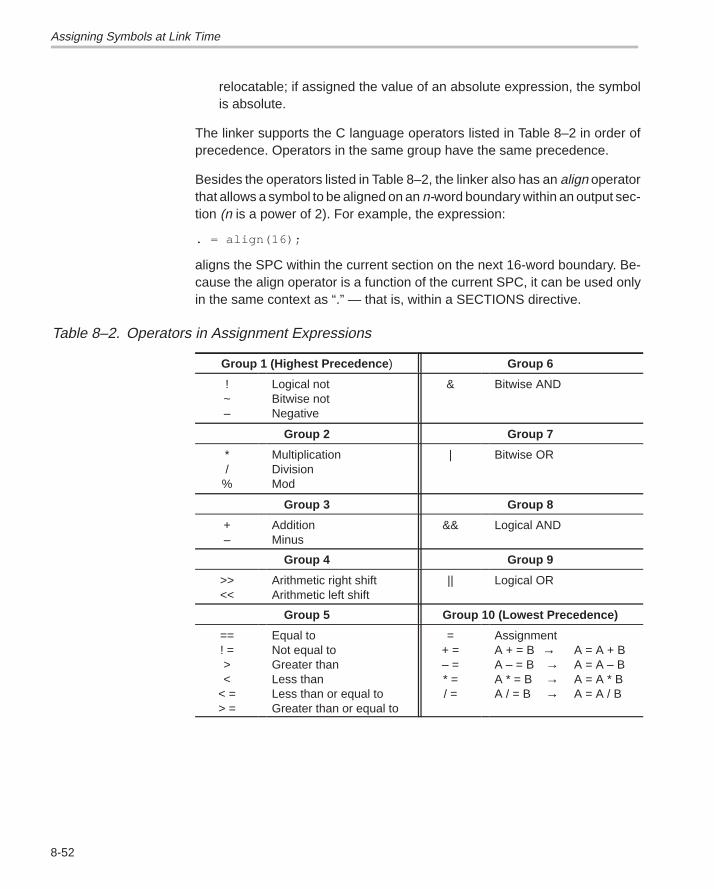
Assigning Symbols at Link Time
8-52
relocatable; if assigned the value of an absolute expression, the symbolis absolute.
The linker supports the C language operators listed in Table 8–2 in order ofprecedence. Operators in the same group have the same precedence.
Besides the operators listed in Table 8–2, the linker also has an align operatorthat allows a symbol to be aligned on an n-word boundary within an output sec-tion (n is a power of 2). For example, the expression:
. = align(16);
aligns the SPC within the current section on the next 16-word boundary. Be-cause the align operator is a function of the current SPC, it can be used onlyin the same context as “.” — that is, within a SECTIONS directive.
Table 8–2. Operators in Assignment Expressions
Group 1 (Highest Precedence ) Group 6
!~–
Logical notBitwise notNegative
& Bitwise AND
Group 2 Group 7
*/
%
MultiplicationDivisionMod
| Bitwise OR
Group 3 Group 8
+–
AdditionMinus
&& Logical AND
Group 4 Group 9
>><<
Arithmetic right shiftArithmetic left shift
|| Logical OR
Group 5 Group 10 (Lowest Precedence)
==! =><
< => =
Equal toNot equal toGreater thanLess thanLess than or equal toGreater than or equal to
=+ =– =* =/ =
AssignmentA + = B → A = A + BA – = B → A = A – BA * = B → A = A * BA / = B → A = A / B
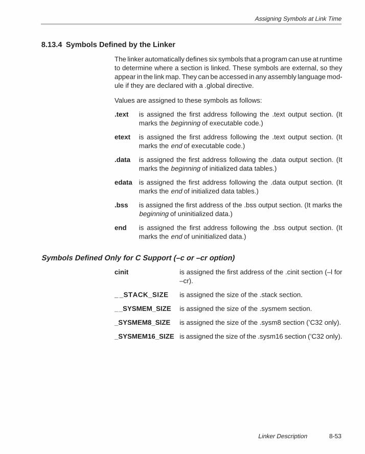
Assigning Symbols at Link Time
8-53Linker Description
8.13.4 Symbols Defined by the Linker
The linker automatically defines six symbols that a program can use at runtimeto determine where a section is linked. These symbols are external, so theyappear in the link map. They can be accessed in any assembly language mod-ule if they are declared with a .global directive.
Values are assigned to these symbols as follows:
.text is assigned the first address following the .text output section. (Itmarks the beginning of executable code.)
etext is assigned the first address following the .text output section. (Itmarks the end of executable code.)
.data is assigned the first address following the .data output section. (Itmarks the beginning of initialized data tables.)
edata is assigned the first address following the .data output section. (Itmarks the end of initialized data tables.)
.bss is assigned the first address of the .bss output section. (It marks thebeginning of uninitialized data.)
end is assigned the first address following the .bss output section. (Itmarks the end of uninitialized data.)
Symbols Defined Only for C Support (–c or –cr option)
cinit is assigned the first address of the .cinit section (–l for–cr).
_ _STACK_SIZE is assigned the size of the .stack section.
__SYSMEM_SIZE is assigned the size of the .sysmem section.
_SYSMEM8_SIZE is assigned the size of the .sysm8 section (’C32 only).
_SYSMEM16_SIZE is assigned the size of the .sysm16 section (’C32 only).
Creating and Filling Holes
8-54
8.14 Creating and Filling Holes
The linker provides you with the ability to create areas within output sectionsthat have nothing linked into them. These areas are called holes . In specialcases, uninitialized sections can also be treated as holes. This section de-scribes how the linker handles such holes and how you can fill holes (anduninitialized sections) with a value.
8.14.1 Initialized and Uninitialized Sections
There are two rules to remember about the contents of an output section. Anoutput section contains either:
� An output section contains raw data for the entire section, or
� An output section contains no raw data.
A section that has raw data is referred to as initialized. This means that theobject file contains the actual memory image contents of the section. When thesection is loaded, this image is loaded into memory at the section’s specifiedstarting address. The .text and .data sections always have raw data if anythingwas assembled into them. Named sections defined with the .sect or .asect as-sembler directives also have raw data.
By default, the .bss section and .usect sections have no raw data (they areuninitialized ). They occupy space in the memory map but have no actual con-tents. Uninitialized sections typically reserve space in RAM for variables. In theobject file, an uninitialized section has a normal section header and may havesymbols defined in it; however, no memory image is stored in the section.
8.14.2 Creating Holes
You can create a hole in an initialized output section. A hole is created whenyou force the linker to leave extra space between input sections when buildingan output section. When such a hole is created, the linker must follow the firstguideline and supply raw data for the hole.
Holes can be created only within output sections. There can also be space be-tween output sections, but such spaces are not holes. There is no way to fillor initialize the space between output sections.
To create a hole in an output section, you must use a special type of linker as-signment statement within an output section definition. The assignment state-ment modifies the SPC (denoted by “.”) by adding to it, assigning a greatervalue to it, or aligning it on an address boundary. The operators, expressions,and syntax of assignment statements are described in Section 8.13 (page8-50).
Creating and Filling Holes
8-55Linker Description
The following example shows how holes can be created in output sectionsusing assignment statements:
SECTIONS{
outsect:{
file1.obj(.text). += 100h; /* Create a hole with size 100h */file2.obj(.text). = align(16); /* Create a hole to align the SPC */file3.obj
}}
The output section outsect is built as follows:
� The .text section from file1.obj is linked in.� The linker creates a 256-word hole.� The .text section from file2.obj is linked in after the hole.� The linker creates another hole by aligning the SPC on a 16-word bound-
ary.� Finally, the .text section from file3.obj is linked in.
All values assigned to the “.” symbol within a section refer to the relativeaddress within the section. The linker handles assignments to the “.” symbolas if the section started at address 0 (even if you specify a binding address).Consider the statement . = align(16) in the preceding example. This statementeffectively aligns file3.obj .text to start on a 16-word boundary within outsect.If outsect is ultimately allocated to start on an address that is not aligned, thenfile3.text will not be aligned either.
Expressions that decrement “.” are illegal. For example, it is invalid to use the–= operator in an assignment to “.”. The most common operators used inassignments to “.” are += and align.
If an output section contains all input sections of a certain type (such as .text),you can use the following statements to create a hole at the beginning or endof the output section:
.text: { .+= 100h; } /* Hole at the beginning */
.data: { *(.data)
. += 100h; } /* Hole at the end */
Creating and Filling Holes
8-56
Another way to create a hole in an output section is to combine an uninitializedsection with initialized sections to form a single output section. In this case, thelinker treats the uninitialized section as a hole and supplies data for it. An ex-ample of creating a hole in this way is:
SECTIONS{
outsect:{
file1.obj(.text)file1.obj(.bss) /* This becomes a hole */
}}
Because the .text section has raw data, all of outsect must also contain rawdata (first guideline). Therefore, the uninitialized .bss section becomes a hole.
Note that uninitialized sections become holes only when they are combinedwith initialized sections. If multiple uninitialized sections are linked together,the resulting output section is also uninitialized.
8.14.3 Filling Holes
Whenever there is a hole in an initialized output section, the linker must supplyraw data to fill it. The linker fills holes with a 4-byte fill value that is replicatedthrough memory until it fills the hole. The linker determines the fill value as fol-lows:
1) If the hole is formed by combining an uninitialized section with an initializedsection, you can specify a fill value for that specific initialized section. Fol-low the section name with an = symbol and a 4-byte constant:
SECTIONS{
outsect:{
file1.obj(.text)file2.obj(.bss) = 0FFh /* Fill this hole */
} /* with 000000FFh */}
2) You can also specify a fill value for all the holes in an output section by us-ing the fill keyword. For example,
SECTIONS{
outsect: fill = 0FF00h /* fills holes with 0FF00h */ {
. += 10h; /* This creates a hole */file1.obj(.text)file1.obj(.bss) /* This creates another hole */
}}
Creating and Filling Holes
8-57Linker Description
3) If you do not specify an initialization value for a hole, the linker fills the holewith the value specified with –f. For example, suppose the command filelink.cmd contains the following SECTIONS directive:
SECTIONS{
.text: { .= 100; } /* Create a 100 - word hole*/}
Now invoke the linker with the –f option:
lnk30 –f 0FFFFFFFFh link.cmd
This fills the hole with 0FFFFFFFFh.
4) If you do not invoke the linker with –f, the linker fills holes with 0s.
Whenever a hole is created and filled in an initialized output section, the holeis identified in the link map along with the value the linker uses to fill it.
8.14.4 Explicit Initialization of Uninitialized Sections
An uninitialized section becomes a hole only when it is combined with an initial-ized section. When uninitialized sections are combined with each other, theresulting output section remains uninitialized and has no raw data in the outputfile.
However, you can force the linker to initialize an uninitialized section simply byspecifying an explicit fill value for it in the SECTIONS directive. This causesthe entire section to have raw data (the fill value). For example,
SECTIONS{
.bss: fill = 11223344h /* Fills .bss with 11223344h */}
Note: Filling Sections
Because filling a section (even with 0s) causes raw data to be generated forthe entire section in the output file, your output file will be very large if youspecify fill values for large sections or holes.
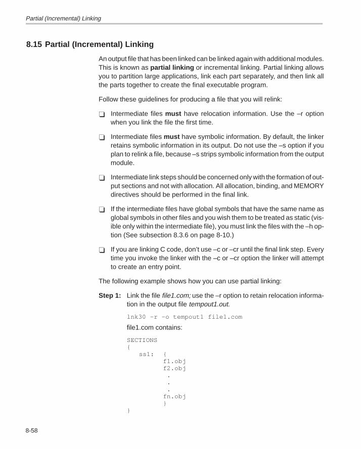
Partial (Incremental) Linking
8-58
8.15 Partial (Incremental) Linking
An output file that has been linked can be linked again with additional modules.This is known as partial linking or incremental linking. Partial linking allowsyou to partition large applications, link each part separately, and then link allthe parts together to create the final executable program.
Follow these guidelines for producing a file that you will relink:
� Intermediate files must have relocation information. Use the –r optionwhen you link the file the first time.
� Intermediate files must have symbolic information. By default, the linkerretains symbolic information in its output. Do not use the –s option if youplan to relink a file, because –s strips symbolic information from the outputmodule.
� Intermediate link steps should be concerned only with the formation of out-put sections and not with allocation. All allocation, binding, and MEMORYdirectives should be performed in the final link.
� If the intermediate files have global symbols that have the same name asglobal symbols in other files and you wish them to be treated as static (vis-ible only within the intermediate file), you must link the files with the –h op-tion (See subsection 8.3.6 on page 8-10.)
� If you are linking C code, don’t use –c or –cr until the final link step. Everytime you invoke the linker with the –c or –cr option the linker will attemptto create an entry point.
The following example shows how you can use partial linking:
Step 1: Link the file file1.com; use the –r option to retain relocation informa-tion in the output file tempout1.out.
lnk30 –r –o tempout1 file1.com
file1.com contains:
SECTIONS{
ss1: {f1.objf2.obj . . .fn.obj}
}
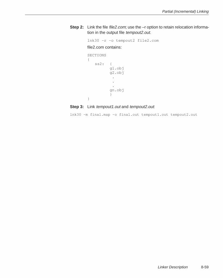
Partial (Incremental) Linking
8-59Linker Description
Step 2: Link the file file2.com; use the –r option to retain relocation informa-tion in the output file tempout2.out.
lnk30 –r –o tempout2 file2.com
file2.com contains:
SECTIONS{
ss2: {g1.objg2.obj .
. .gn.obj}
}
Step 3: Link tempout1.out and tempout2.out:
lnk30 –m final.map –o final.out tempout1.out tempout2.out
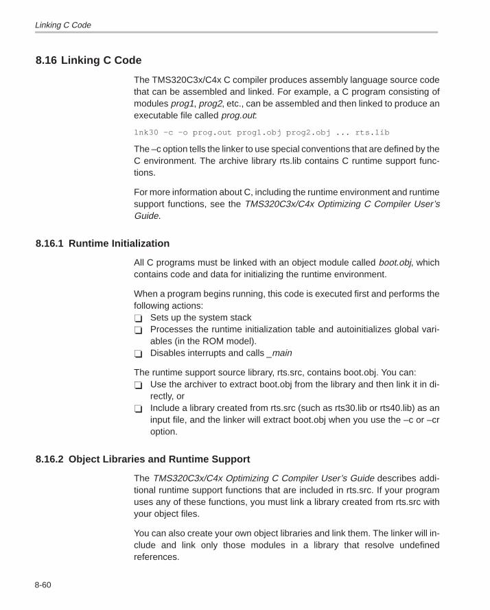
Linking C Code
8-60
8.16 Linking C Code
The TMS320C3x/C4x C compiler produces assembly language source codethat can be assembled and linked. For example, a C program consisting ofmodules prog1, prog2, etc., can be assembled and then linked to produce anexecutable file called prog.out:
lnk30 –c –o prog.out prog1.obj prog2.obj ... rts.lib
The –c option tells the linker to use special conventions that are defined by theC environment. The archive library rts.lib contains C runtime support func-tions.
For more information about C, including the runtime environment and runtimesupport functions, see the TMS320C3x/C4x Optimizing C Compiler User’sGuide.
8.16.1 Runtime Initialization
All C programs must be linked with an object module called boot.obj, whichcontains code and data for initializing the runtime environment.
When a program begins running, this code is executed first and performs thefollowing actions:� Sets up the system stack� Processes the runtime initialization table and autoinitializes global vari-
ables (in the ROM model).� Disables interrupts and calls _main
The runtime support source library, rts.src, contains boot.obj. You can:� Use the archiver to extract boot.obj from the library and then link it in di-
rectly, or� Include a library created from rts.src (such as rts30.lib or rts40.lib) as an
input file, and the linker will extract boot.obj when you use the –c or –croption.
8.16.2 Object Libraries and Runtime Support
The TMS320C3x/C4x Optimizing C Compiler User’s Guide describes addi-tional runtime support functions that are included in rts.src. If your programuses any of these functions, you must link a library created from rts.src withyour object files.
You can also create your own object libraries and link them. The linker will in-clude and link only those modules in a library that resolve undefinedreferences.
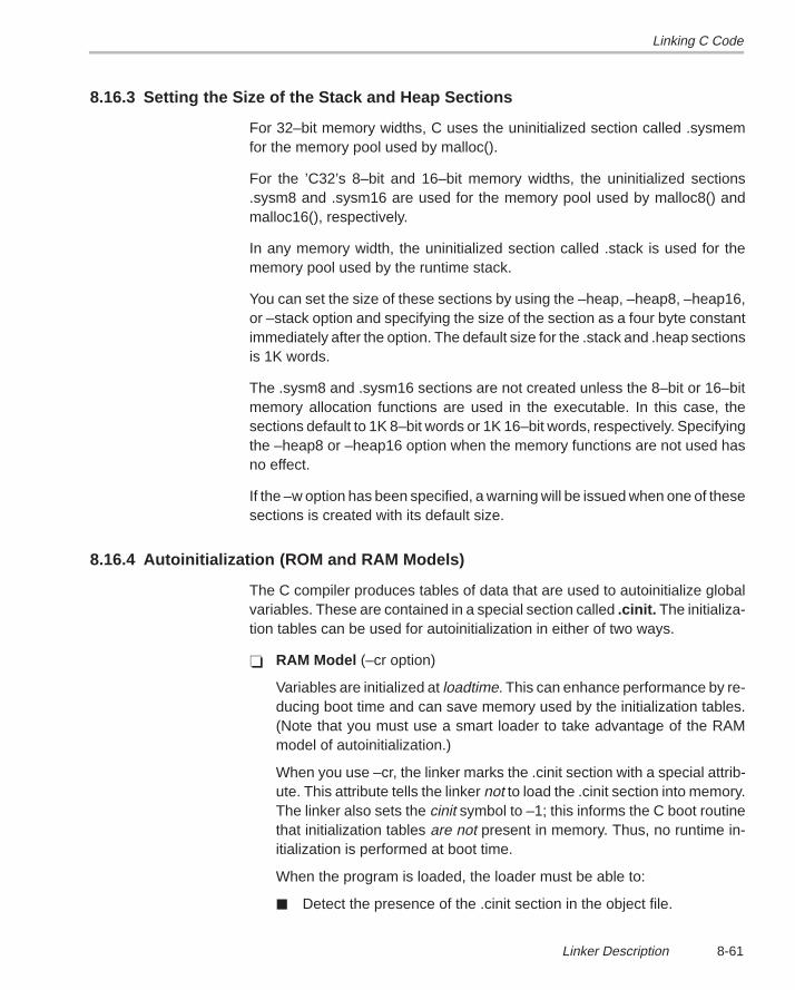
Linking C Code
8-61Linker Description
8.16.3 Setting the Size of the Stack and Heap Sections
For 32–bit memory widths, C uses the uninitialized section called .sysmemfor the memory pool used by malloc().
For the ’C32’s 8–bit and 16–bit memory widths, the uninitialized sections.sysm8 and .sysm16 are used for the memory pool used by malloc8() andmalloc16(), respectively.
In any memory width, the uninitialized section called .stack is used for thememory pool used by the runtime stack.
You can set the size of these sections by using the –heap, –heap8, –heap16,or –stack option and specifying the size of the section as a four byte constantimmediately after the option. The default size for the .stack and .heap sectionsis 1K words.
The .sysm8 and .sysm16 sections are not created unless the 8–bit or 16–bitmemory allocation functions are used in the executable. In this case, thesections default to 1K 8–bit words or 1K 16–bit words, respectively. Specifyingthe –heap8 or –heap16 option when the memory functions are not used hasno effect.
If the –w option has been specified, a warning will be issued when one of thesesections is created with its default size.
8.16.4 Autoinitialization (ROM and RAM Models)
The C compiler produces tables of data that are used to autoinitialize globalvariables. These are contained in a special section called .cinit. The initializa-tion tables can be used for autoinitialization in either of two ways.
� RAM Model (–cr option)
Variables are initialized at loadtime. This can enhance performance by re-ducing boot time and can save memory used by the initialization tables.(Note that you must use a smart loader to take advantage of the RAMmodel of autoinitialization.)
When you use –cr, the linker marks the .cinit section with a special attrib-ute. This attribute tells the linker not to load the .cinit section into memory.The linker also sets the cinit symbol to –1; this informs the C boot routinethat initialization tables are not present in memory. Thus, no runtime in-itialization is performed at boot time.
When the program is loaded, the loader must be able to:
� Detect the presence of the .cinit section in the object file.
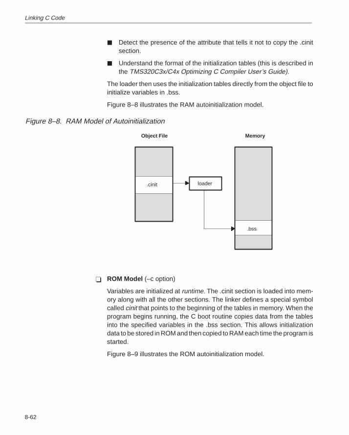
Linking C Code
8-62
� Detect the presence of the attribute that tells it not to copy the .cinitsection.
� Understand the format of the initialization tables (this is described inthe TMS320C3x/C4x Optimizing C Compiler User’s Guide).
The loader then uses the initialization tables directly from the object file toinitialize variables in .bss.
Figure 8–8 illustrates the RAM autoinitialization model.
Figure 8–8. RAM Model of Autoinitialization
.cinit
Object File
.bss
loader
Memory
� ROM Model (–c option)
Variables are initialized at runtime. The .cinit section is loaded into mem-ory along with all the other sections. The linker defines a special symbolcalled cinit that points to the beginning of the tables in memory. When theprogram begins running, the C boot routine copies data from the tablesinto the specified variables in the .bss section. This allows initializationdata to be stored in ROM and then copied to RAM each time the program isstarted.
Figure 8–9 illustrates the ROM autoinitialization model.
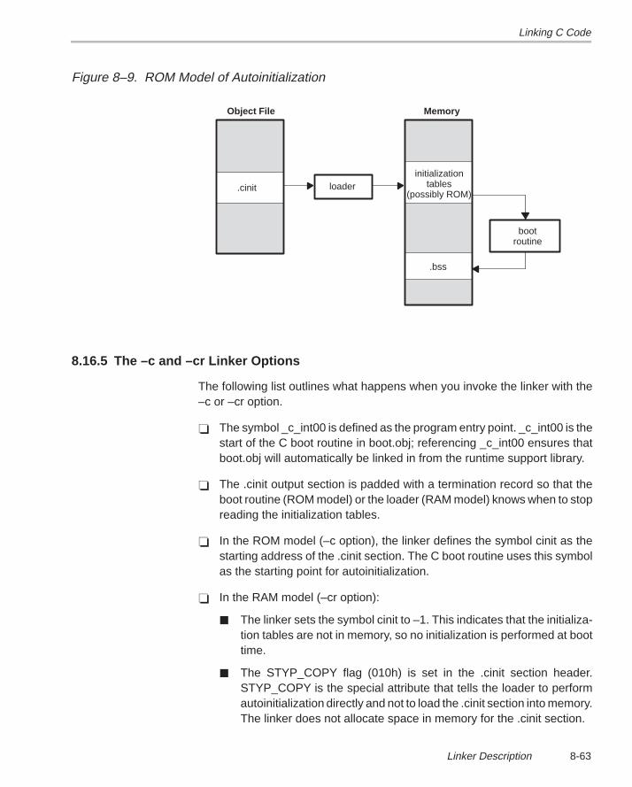
Linking C Code
8-63Linker Description
Figure 8–9. ROM Model of Autoinitialization
.cinit
Object File
.bss
loader
Memory
bootroutine
initializationtables
(possibly ROM)
8.16.5 The –c and –cr Linker Options
The following list outlines what happens when you invoke the linker with the–c or –cr option.
� The symbol _c_int00 is defined as the program entry point. _c_int00 is thestart of the C boot routine in boot.obj; referencing _c_int00 ensures thatboot.obj will automatically be linked in from the runtime support library.
� The .cinit output section is padded with a termination record so that theboot routine (ROM model) or the loader (RAM model) knows when to stopreading the initialization tables.
� In the ROM model (–c option), the linker defines the symbol cinit as thestarting address of the .cinit section. The C boot routine uses this symbolas the starting point for autoinitialization.
� In the RAM model (–cr option):
� The linker sets the symbol cinit to –1. This indicates that the initializa-tion tables are not in memory, so no initialization is performed at boottime.
� The STYP_COPY flag (010h) is set in the .cinit section header.STYP_COPY is the special attribute that tells the loader to performautoinitialization directly and not to load the .cinit section into memory.The linker does not allocate space in memory for the .cinit section.
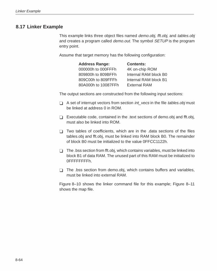
Linker Example
8-64
8.17 Linker Example
This example links three object files named demo.obj, fft.obj, and tables.objand creates a program called demo.out. The symbol SETUP is the programentry point.
Assume that target memory has the following configuration:
Address Range: Contents:000000h to 000FFFh 4K on-chip ROM809800h to 809BFFh Internal RAM block B0809C00h to 809FFFh Internal RAM block B180A000h to 10087FFh External RAM
The output sections are constructed from the following input sections:
� A set of interrupt vectors from section int_vecs in the file tables.obj mustbe linked at address 0 in ROM.
� Executable code, contained in the .text sections of demo.obj and fft.obj,must also be linked into ROM.
� Two tables of coefficients, which are in the .data sections of the filestables.obj and fft.obj, must be linked into RAM block B0. The remainderof block B0 must be initialized to the value 0FFCC1122h.
� The .bss section from fft.obj, which contains variables, must be linked intoblock B1 of data RAM. The unused part of this RAM must be initialized to0FFFFFFFFh.
� The .bss section from demo.obj, which contains buffers and variables,must be linked into external RAM.
Figure 8–10 shows the linker command file for this example; Figure 8–11shows the map file.
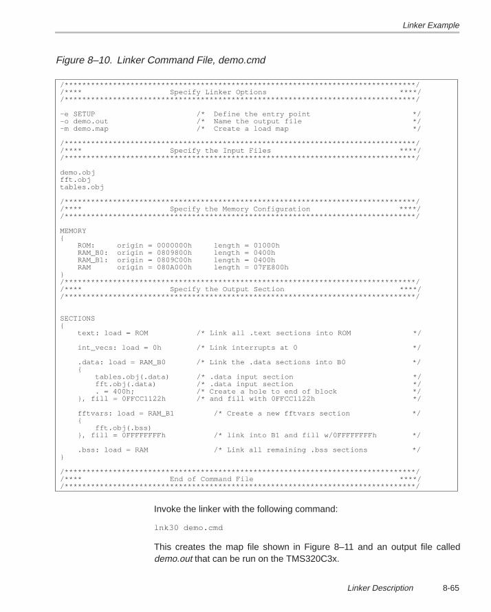
Linker Example
8-65Linker Description
Figure 8–10. Linker Command File, demo.cmd
/********************************************************************************//**** Specify Linker Options ****//********************************************************************************/
–e SETUP /* Define the entry point */–o demo.out /* Name the output file */–m demo.map /* Create a load map */
/********************************************************************************//**** Specify the Input Files ****//********************************************************************************/
demo.objfft.objtables.obj
/********************************************************************************//**** Specify the Memory Configuration ****//********************************************************************************/
MEMORY{
ROM: origin = 0000000h length = 01000hRAM_B0: origin = 0809800h length = 0400hRAM_B1: origin = 0809C00h length = 0400hRAM origin = 080A000h length = 07FE800h
}/********************************************************************************//**** Specify the Output Section ****//********************************************************************************/
SECTIONS{
text: load = ROM /* Link all .text sections into ROM */
int_vecs: load = 0h /* Link interrupts at 0 */
.data: load = RAM_B0 /* Link the .data sections into B0 */{
tables.obj(.data) /* .data input section */fft.obj(.data) /* .data input section */. = 400h; /* Create a hole to end of block */
}, fill = 0FFCC1122h /* and fill with 0FFCC1122h */
fftvars: load = RAM_B1 /* Create a new fftvars section */{
fft.obj(.bss)}, fill = 0FFFFFFFFh /* link into B1 and fill w/0FFFFFFFFh */
.bss: load = RAM /* Link all remaining .bss sections */}
/********************************************************************************//**** End of Command File ****//********************************************************************************/
Invoke the linker with the following command:
lnk30 demo.cmd
This creates the map file shown in Figure 8–11 and an output file calleddemo.out that can be run on the TMS320C3x.
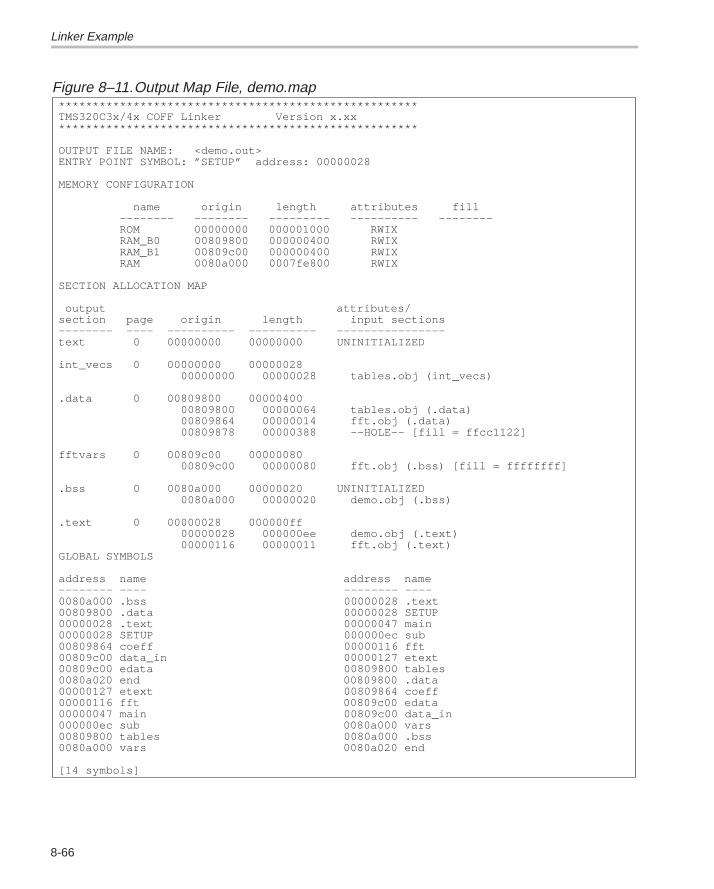
Linker Example
8-66
Figure 8–11.Output Map File, demo.map*****************************************************TMS320C3x/4x COFF Linker Version x.xx*****************************************************
OUTPUT FILE NAME: <demo.out>ENTRY POINT SYMBOL: ”SETUP” address: 00000028
MEMORY CONFIGURATION
name origin length attributes fill –––––––– –––––––– ––––––––– –––––––––– –––––––– ROM 00000000 000001000 RWIX RAM_B0 00809800 000000400 RWIX RAM_B1 00809c00 000000400 RWIX RAM 0080a000 0007fe800 RWIX
SECTION ALLOCATION MAP
output attributes/section page origin length input sections–––––––– –––– –––––––––– –––––––––– ––––––––––––––––text 0 00000000 00000000 UNINITIALIZED
int_vecs 0 00000000 00000028 00000000 00000028 tables.obj (int_vecs)
.data 0 00809800 00000400 00809800 00000064 tables.obj (.data) 00809864 00000014 fft.obj (.data) 00809878 00000388 ––HOLE–– [fill = ffcc1122]
fftvars 0 00809c00 00000080 00809c00 00000080 fft.obj (.bss) [fill = ffffffff]
.bss 0 0080a000 00000020 UNINITIALIZED 0080a000 00000020 demo.obj (.bss)
.text 0 00000028 000000ff 00000028 000000ee demo.obj (.text) 00000116 00000011 fft.obj (.text)GLOBAL SYMBOLS
address name address name–––––––– –––– –––––––– ––––0080a000 .bss 00000028 .text00809800 .data 00000028 SETUP00000028 .text 00000047 main00000028 SETUP 000000ec sub00809864 coeff 00000116 fft00809c00 data_in 00000127 etext00809c00 edata 00809800 tables0080a020 end 00809800 .data00000127 etext 00809864 coeff00000116 fft 00809c00 edata00000047 main 00809c00 data_in000000ec sub 0080a000 vars00809800 tables 0080a000 .bss0080a000 vars 0080a020 end
[14 symbols]
9-1Absolute Lister Description
Absolute Lister Description
The absolute lister is a debugging tool that accepts linked object files as inputand creates .abs files as output. These .abs files can be assembled to producea listing that shows the absolute addresses of object code. Manually, this couldbe a tedious process requiring many operations; however, the absolute listerutility performs these operations automatically.
Topic Page
9.1 Producing an Absolute Listing 9-2. . . . . . . . . . . . . . . . . . . . . . . . . . . . . . . . .
9.2 Invoking the Absolute Lister 9-3. . . . . . . . . . . . . . . . . . . . . . . . . . . . . . . . . . .
9.3 Absolute Lister Example 9-5. . . . . . . . . . . . . . . . . . . . . . . . . . . . . . . . . . . . . . .
Chapter 9
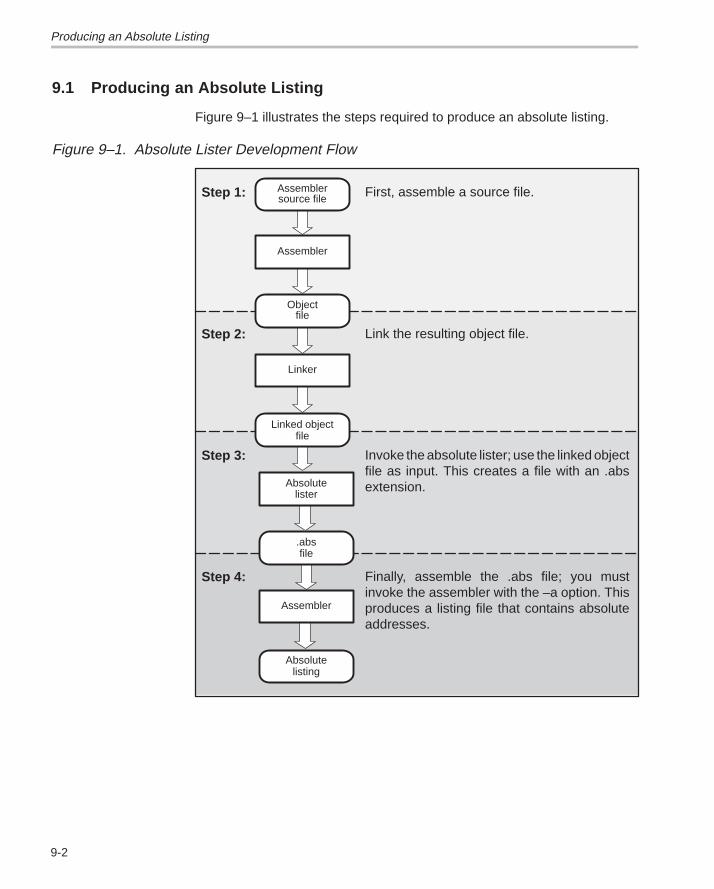
Producing an Absolute Listing
9-2
9.1 Producing an Absolute Listing
Figure 9–1 illustrates the steps required to produce an absolute listing.
Figure 9–1. Absolute Lister Development Flow
ÍÍÍÍ
ÍÍÍÍ
ÍÍÍÍÍÍÍÍÍÍ
ÍÍÍÍ
Assembler
Objectfile
Linked objectfile
Linker
First, assemble a source file.
Link the resulting object file.
Invoke the absolute lister; use the linked objectfile as input. This creates a file with an .absextension.
Step 1:
Step 2:
Step 3:
ÍÍÍÍÍÍ
ÍÍÍÍÍÍ
ÍÍÍÍ
Absolute
Assembler
lister
Absolute
.absfile
Finally, assemble the .abs file; you mustinvoke the assembler with the –a option. Thisproduces a listing file that contains absoluteaddresses.
Step 4:
Assemblersource file
listing
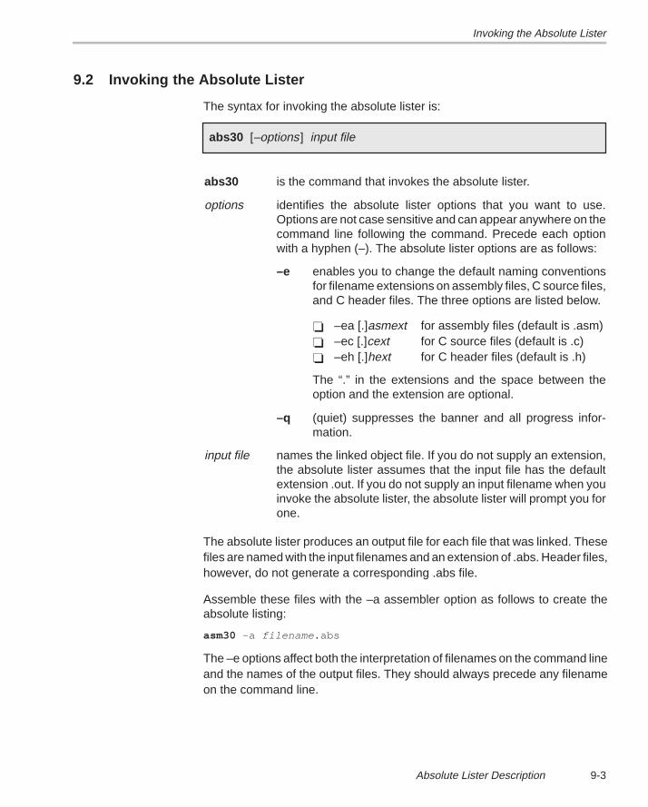
Invoking the Absolute Lister
9-3Absolute Lister Description
9.2 Invoking the Absolute Lister
The syntax for invoking the absolute lister is:
abs30 [–options] input file
abs30 is the command that invokes the absolute lister.
options identifies the absolute lister options that you want to use.Options are not case sensitive and can appear anywhere on thecommand line following the command. Precede each optionwith a hyphen (–). The absolute lister options are as follows:
–e enables you to change the default naming conventionsfor filename extensions on assembly files, C source files,and C header files. The three options are listed below.
� –ea [.]asmext for assembly files (default is .asm)� –ec [.]cext for C source files (default is .c)� –eh [.]hext for C header files (default is .h)
The “.” in the extensions and the space between theoption and the extension are optional.
–q (quiet) suppresses the banner and all progress infor-mation.
input file names the linked object file. If you do not supply an extension,the absolute lister assumes that the input file has the defaultextension .out. If you do not supply an input filename when youinvoke the absolute lister, the absolute lister will prompt you forone.
The absolute lister produces an output file for each file that was linked. Thesefiles are named with the input filenames and an extension of .abs. Header files,however, do not generate a corresponding .abs file.
Assemble these files with the –a assembler option as follows to create theabsolute listing:
asm30 –a filename .abs
The –e options affect both the interpretation of filenames on the command lineand the names of the output files. They should always precede any filenameon the command line.
Invoking the Absolute Lister
9-4
The –e options are particularly useful when:
� the linked object file is created from C files compiled with the debuggingoption (–g compiler option) and
� the source files do not use the standard extensions (.c for C source files,.h for header files, and .asm for assembly files).
The absolute lister uses file extensions to determine how to treat the sourcefiles listed in the linked object file.
For example, suppose the C source file hello.csr is compiled with debuggingset; this generates the assembly file hello.s. hello.csr also includes hello.hsr.Assuming the executable file created is called hello.out, the followingcommand will generate the proper .abs file:
abs30 –ea s –ec csr –eh hsr hello.out
With the –e options appropriately specified in this example, the absolute listerwill:
� recognize hello.hsr as a header file and therefore not create an .abs filefor it
� create hello.abs for the hello.csr file
� use the .copy directive within the hello.abs file to include assembly filehello.s, rather than hello.asm
Note that you need to use the –k compiler option when compiling the originalsource file so that you retain the assembly files for inclusion when you re-assemble the .abs files.
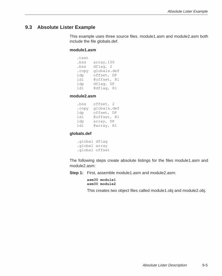
Absolute Lister Example
9-5Absolute Lister Description
9.3 Absolute Lister Example
This example uses three source files. module1.asm and module2.asm bothinclude the file globals.def.
module1.asm
.text .bss array,100 .bss dflag, 2 .copy globals.def ldp offset, DP ldi @offset, R1 ldp dflag, DP ldi @dflag, R1
module2.asm
.bss offset, 2 .copy globals.def ldp offset, DP ldi @offset, R1 ldp array, DP ldi @array, R1
globals.def
.global dflag .global array .global offset
The following steps create absolute listings for the files module1.asm andmodule2.asm:
Step 1: First, assemble module1.asm and module2.asm:
asm30 module1asm30 module2
This creates two object files called module1.obj and module2.obj.
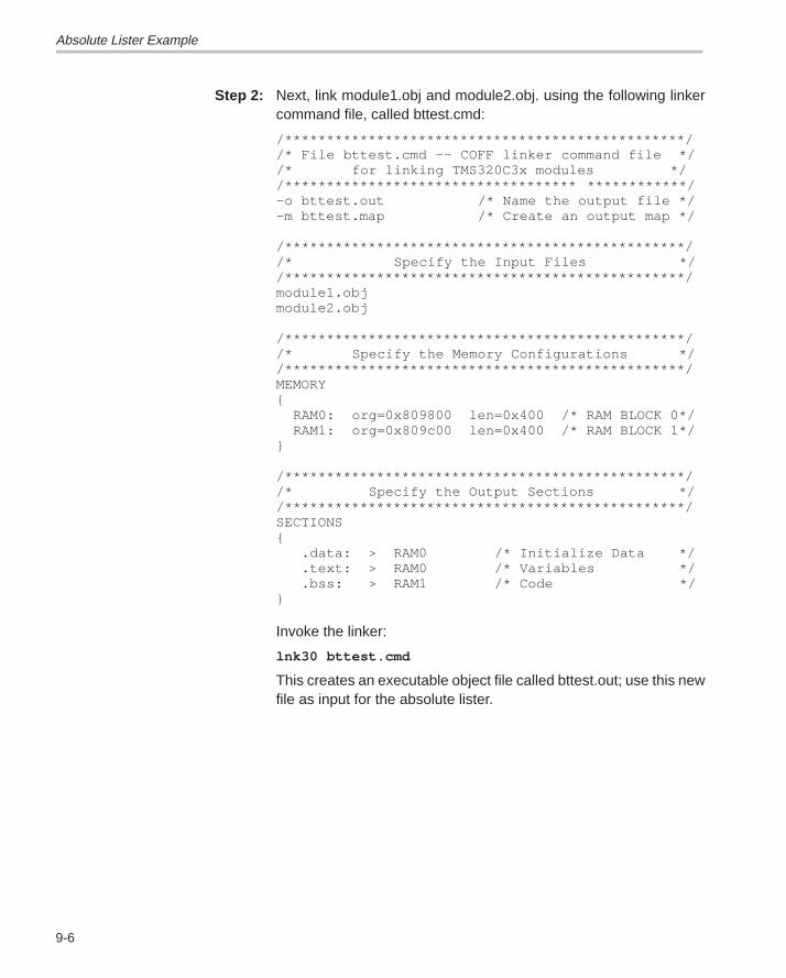
Absolute Lister Example
9-6
Step 2: Next, link module1.obj and module2.obj. using the following linkercommand file, called bttest.cmd:
/************************************************//* File bttest.cmd –– COFF linker command file *//* for linking TMS320C3x modules *//*********************************** ************/–o bttest.out /* Name the output file */–m bttest.map /* Create an output map */
/************************************************//* Specify the Input Files *//************************************************/module1.objmodule2.obj
/************************************************//* Specify the Memory Configurations *//************************************************/MEMORY{ RAM0: org=0x809800 len=0x400 /* RAM BLOCK 0*/ RAM1: org=0x809c00 len=0x400 /* RAM BLOCK 1*/}
/************************************************//* Specify the Output Sections *//************************************************/SECTIONS{ .data: > RAM0 /* Initialize Data */ .text: > RAM0 /* Variables */ .bss: > RAM1 /* Code */}
Invoke the linker:
lnk30 bttest.cmd
This creates an executable object file called bttest.out; use this newfile as input for the absolute lister.
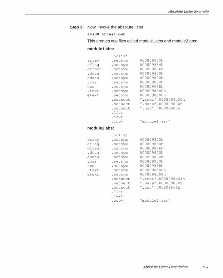
Absolute Lister Example
9-7Absolute Lister Description
Step 3: Now, invoke the absolute lister:
abs30 bttest.out
This creates two files called module1.abs and module2.abs:
module1.abs:
.nolistarray .setsym 000809800hdflag .setsym 000809864hoffset .setsym 000809866h.data .setsym 000809800hedata .setsym 000809800h.bss .setsym 000809800hend .setsym 000809868h.text .setsym 0008098c00hetext .setsym 0008098c08h .setsect ”.text”,0008098c00h .setsect ”.data”,000809800h .setsect ”.bss”,000809800h .list .text .copy ”module1.asm”
module2.abs:
.nolistarray .setsym 000809800hdflag .setsym 000809864hoffset .setsym 000809866h.data .setsym 000809800hedata .setsym 000809800h.bss .setsym 000809800hend .setsym 000809868h.text .setsym 0008098c00hetext .setsym 0008098c08h .setsect ”.text”,0008098c04h .setsect ”.data”,000809800h .setsect ”.bss”,000809866h .list .text .copy ”module2.asm”
Absolute Lister Example
9-8
These files contain the following information that the assemblerneeds when you invoke it in step 4:
� They contain .setsym directives, which equate values to globalsymbols. Both files contain global equates for the symbol dflag.The symbol dflag was defined in the file globals.def, which wasincluded in module1.asm and module2.asm.
� They contain .setsect directives, which define the absoluteaddresses for sections.
� They contain .copy directives, which tell the assembler whichassembly language source file to include.
The .setsym and .setsect directives are not useful in normal assem-bly; they are useful only for creating absolute listings.
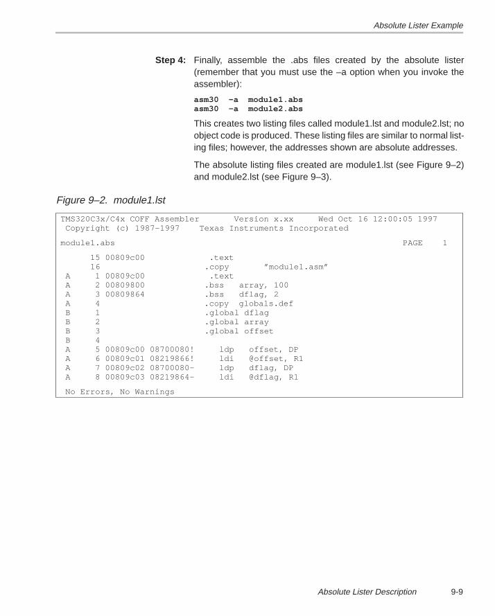
Absolute Lister Example
9-9Absolute Lister Description
Step 4: Finally, assemble the .abs files created by the absolute lister(remember that you must use the –a option when you invoke theassembler):
asm30 –a module1.absasm30 –a module2.abs
This creates two listing files called module1.lst and module2.lst; noobject code is produced. These listing files are similar to normal list-ing files; however, the addresses shown are absolute addresses.
The absolute listing files created are module1.lst (see Figure 9–2)and module2.lst (see Figure 9–3).
Figure 9–2. module1.lst
TMS320C3x/C4x COFF Assembler Version x.xx Wed Oct 16 12:00:05 1997 Copyright (c) 1987–1997 Texas Instruments Incorporated
module1.abs PAGE 1
15 00809c00 .text 16 .copy ”module1.asm” A 1 00809c00 .text A 2 00809800 .bss array, 100 A 3 00809864 .bss dflag, 2 A 4 .copy globals.def B 1 .global dflag B 2 .global array B 3 .global offset B 4 A 5 00809c00 08700080! ldp offset, DP A 6 00809c01 08219866! ldi @offset, R1 A 7 00809c02 08700080– ldp dflag, DP A 8 00809c03 08219864– ldi @dflag, R1
No Errors, No Warnings
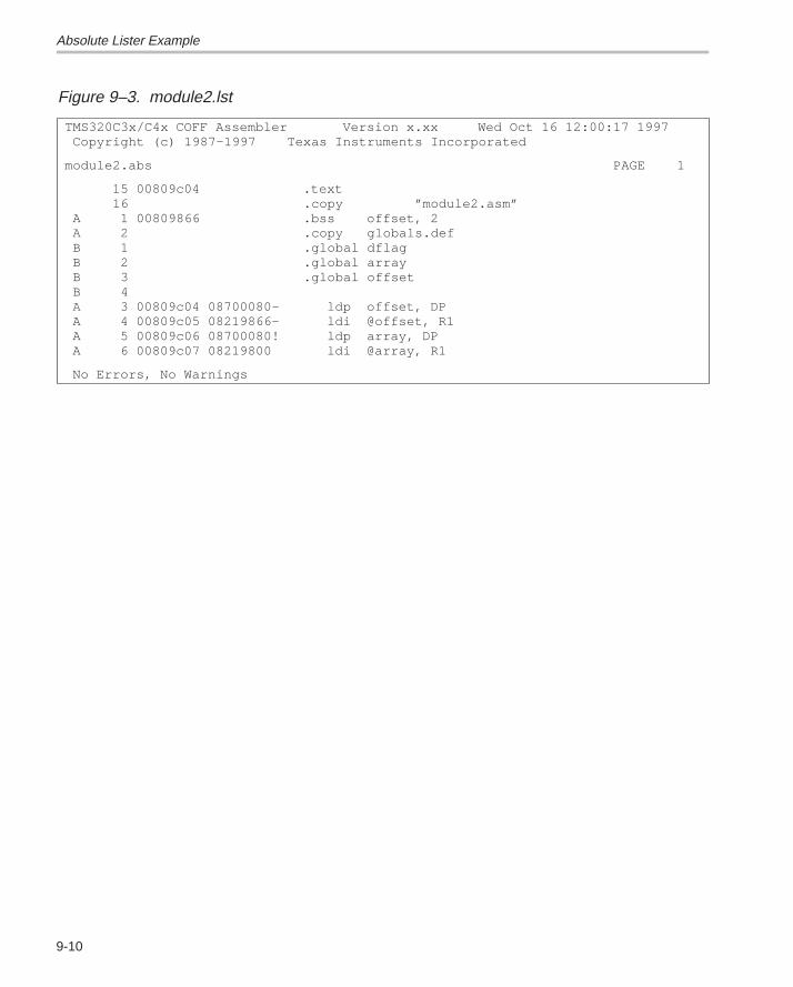
Absolute Lister Example
9-10
Figure 9–3. module2.lst
TMS320C3x/C4x COFF Assembler Version x.xx Wed Oct 16 12:00:17 1997 Copyright (c) 1987–1997 Texas Instruments Incorporated
module2.abs PAGE 1
15 00809c04 .text 16 .copy ”module2.asm” A 1 00809866 .bss offset, 2 A 2 .copy globals.def B 1 .global dflag B 2 .global array B 3 .global offset B 4 A 3 00809c04 08700080– ldp offset, DP A 4 00809c05 08219866– ldi @offset, R1 A 5 00809c06 08700080! ldp array, DP A 6 00809c07 08219800 ldi @array, R1
No Errors, No Warnings
10-1Hex Conversion Utility Description
Hex Conversion Utility Description
The TMS320C3x/C4x assembler and linker create object files that are incommon object file format (COFF), a binary object file format that encouragesmodular programming and provides flexible methods for managing codesegments.
Most EPROM programmers do not accept COFF object files as input. The hexconversion utility translates a COFF object file into one of several standardASCII hexadecimal formats, suitable for loading into an EPROM programmer.The utility is also useful in other applications that require a hexadecimaltranslation of a COFF object file (for example, debuggers and loaders). Thisutility also supports the on-chip boot loader built into the ’C3x or ’C4x,automating the code creation process for the ’C3x and ’C4x.
The hex conversion utility can produce these output file formats:� ASCII-Hex, supporting 16-bit addresses� Extended Tektronix Hexadecimal (Tektronix), supporting 32-bit addresses� Intel MCS-86 Hexadecimal (Intel) supporting 32-bit addresses� Motorola Exorciser (Motorola-S), supporting 16-bit, 24-bit, and 32-bit
addresses� Texas Instruments SDSMAC (TI-Tagged), supporting 16-bit addresses
Topic Page
10.1 Hex Conversion Utility Development Flow 10-2. . . . . . . . . . . . . . . . . . 10.2 Invoking the Hex Conversion Utility 10-3. . . . . . . . . . . . . . . . . . . . . . . . 10.3 Using Command Files 10-6. . . . . . . . . . . . . . . . . . . . . . . . . . . . . . . . . . . . . 10.4 Creating a Compatible File Format 10-7. . . . . . . . . . . . . . . . . . . . . . . . . 10.5 Using the ROMS Directive to Specify Memory
Configuration 10-16. . . . . . . . . . . . . . . . . . . . . . . . . . . . . . . . . . . . . . . . . . . 10.6 Using the SECTIONS Directive to Convert COFF File
Sections 10-22. . . . . . . . . . . . . . . . . . . . . . . . . . . . . . . . . . . . . . . . . . . . . . . . 10.7 Output Filenames 10-24. . . . . . . . . . . . . . . . . . . . . . . . . . . . . . . . . . . . . . . . 10.8 Image Mode and the –fill Option 10-26. . . . . . . . . . . . . . . . . . . . . . . . . . 10.9 Building a Boot Table From an On-Chip Boot Loader 10-28. . . . . . . 10.10 Controlling the ROM Device Address 10-39. . . . . . . . . . . . . . . . . . . . . . 10.11 Description of the Object Formats 10-43. . . . . . . . . . . . . . . . . . . . . . . . 10.12 Hex Conversion Utility Error Messages 10-49. . . . . . . . . . . . . . . . . . . .
Chapter 10
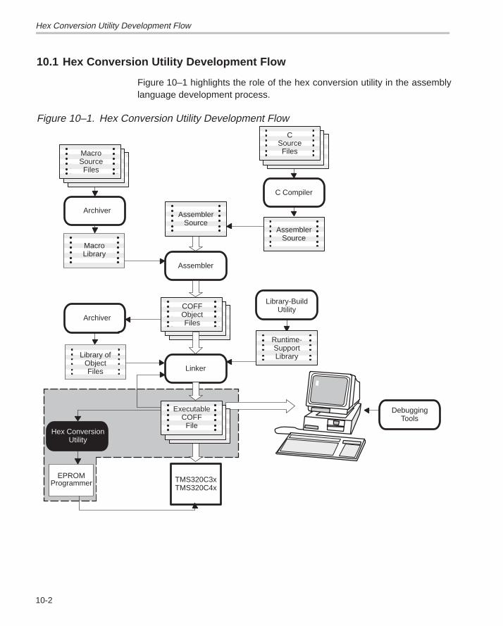
Hex Conversion Utility Development Flow
10-2
10.1 Hex Conversion Utility Development Flow
Figure 10–1 highlights the role of the hex conversion utility in the assemblylanguage development process.
Figure 10–1. Hex Conversion Utility Development Flow
Assembler
Linker
MacroLibrary
Library ofObjectFiles
Hex ConversionUtility
EPROMProgrammer
AssemblerSource
COFFObjectFiles
Archiver
MacroSourceFiles
Archiver
CSourceFiles
TMS320C3xTMS320C4x
C Compiler
AssemblerSource
Library-BuildUtility
DebuggingTools
Runtime-SupportLibrary
ExecutableCOFF
File
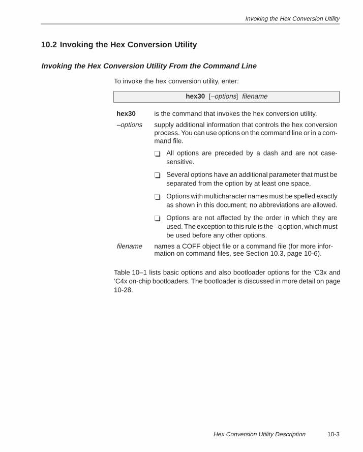
Invoking the Hex Conversion Utility
10-3Hex Conversion Utility Description
10.2 Invoking the Hex Conversion Utility
Invoking the Hex Conversion Utility From the Command Line
To invoke the hex conversion utility, enter:
hex30 [–options] filename
hex30 is the command that invokes the hex conversion utility.
–options supply additional information that controls the hex conversionprocess. You can use options on the command line or in a com-mand file.
� All options are preceded by a dash and are not case-sensitive.
� Several options have an additional parameter that must beseparated from the option by at least one space.
� Options with multicharacter names must be spelled exactlyas shown in this document; no abbreviations are allowed.
� Options are not affected by the order in which they areused. The exception to this rule is the –q option, which mustbe used before any other options.
filename names a COFF object file or a command file (for more infor-mation on command files, see Section 10.3, page 10-6).
Table 10–1 lists basic options and also bootloader options for the ’C3x and’C4x on-chip bootloaders. The bootloader is discussed in more detail on page10-28.
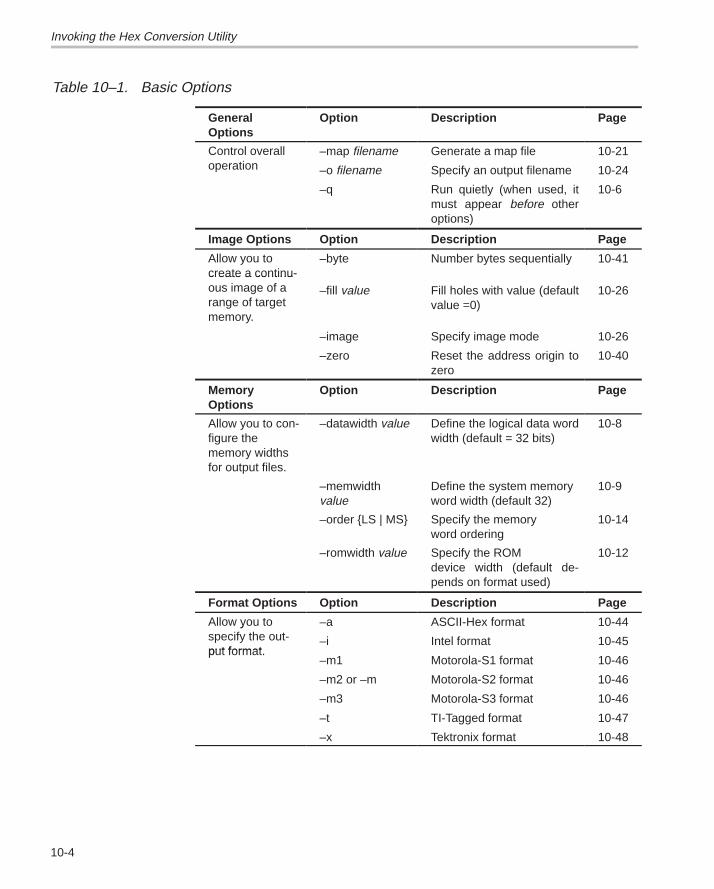
Invoking the Hex Conversion Utility
10-4
Table 10–1. Basic Options
GeneralOptions
Option Description Page
Control overall –map filename Generate a map file 10-21operation –o filename Specify an output filename 10-24
–q Run quietly (when used, itmust appear before otheroptions)
10-6
Image Options Option Description Page
Allow you tocreate a continu-
–byte Number bytes sequentially 10-41create a continuous image of arange of targetmemory.
–fill value Fill holes with value (defaultvalue =0)
10-26
–image Specify image mode 10-26
–zero Reset the address origin tozero
10-40
Memory Options
Option Description Page
Allow you to con-figure thememory widthsfor output files.
–datawidth value Define the logical data wordwidth (default = 32 bits)
10-8
–memwidth value
Define the system memory word width (default 32)
10-9
–order {LS | MS} Specify the memory word ordering
10-14
–romwidth value Specify the ROM device width (default de-pends on format used)
10-12
Format Options Option Description Page
Allow you to –a ASCII-Hex format 10-44yspecify the out-put format
–i Intel format 10-45put format.
–m1 Motorola-S1 format 10-46
–m2 or –m Motorola-S2 format 10-46
–m3 Motorola-S3 format 10-46
–t TI-Tagged format 10-47
–x Tektronix format 10-48
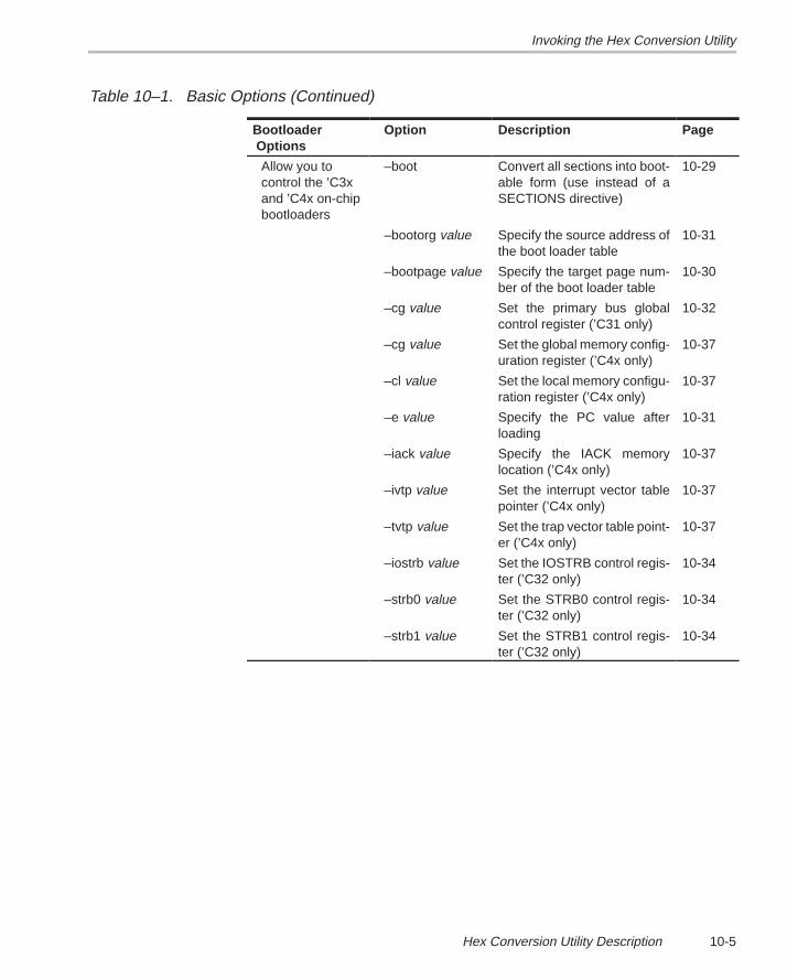
Invoking the Hex Conversion Utility
10-5Hex Conversion Utility Description
Table 10–1. Basic Options (Continued)
Bootloader Options
Option Description Page
Allow you tocontrol the ’C3xand ’C4x on-chipbootloaders
–boot Convert all sections into boot-able form (use instead of aSECTIONS directive)
10-29
–bootorg value Specify the source address ofthe boot loader table
10-31
–bootpage value Specify the target page num-ber of the boot loader table
10-30
–cg value Set the primary bus globalcontrol register (’C31 only)
10-32
–cg value Set the global memory config-uration register (’C4x only)
10-37
–cl value Set the local memory configu-ration register (’C4x only)
10-37
–e value Specify the PC value afterloading
10-31
–iack value Specify the IACK memorylocation (’C4x only)
10-37
–ivtp value Set the interrupt vector tablepointer (’C4x only)
10-37
–tvtp value Set the trap vector table point-er (’C4x only)
10-37
–iostrb value Set the IOSTRB control regis-ter (’C32 only)
10-34
–strb0 value Set the STRB0 control regis-ter (’C32 only)
10-34
–strb1 value Set the STRB1 control regis-ter (’C32 only)
10-34
Using Command Files
10-6
10.3 Using Command Files
Using a command file is useful if you plan to invoke the utility more than oncewith the same input files and options. It is also useful if you want to use theROMS and SECTIONS hex conversion utility directives to customize the con-version process.
Command files are ASCII files that contain one or more of the following:
� Options and filenames. These are specified in a command file in exactlythe same manner as on the command line.
� ROMS directives. The ROMS directive defines the physical memory con-figuration of your system as a list of address-range parameters.
� SECTIONS directives. The SECTIONS directive specifies which sec-tions from the COFF object file should be selected. You can also use thisdirective to identify specific sections that will be initialized by an on-chipboot loader. For more information about the ROMS or SECTIONS direc-tives, see Section 10.5 or 10.6, respectively. For more information on theon-chip boot loader, see Section 10.9, page 10-28.
� Comments. You can add comments to your command file by using the /*and */ delimiters. For example: /* this is a comment */
To invoke the utility and use the options you defined in a command file, enter:
hex30 commandfilename
You can also specify other options and files on the command line. You couldinvoke the utility using both a command file and command line options:
hex30 firmware.cmd –map firmware.mxp
The order in which these options and file names appear is not important. Theutility reads all input from the command line and all information from thecommand file before starting the conversion process. However, if you are us-ing the –q option, it must appear as the first option on the command line or ina command file.
The –q option suppresses the utility’s normal banner and progressinformation.
hex30 –t firmware –o firm.lsb –o firm.msb
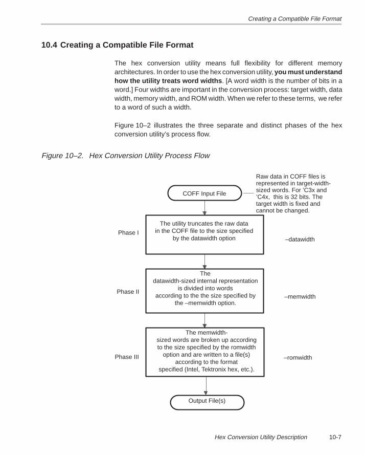
Creating a Compatible File Format
10-7Hex Conversion Utility Description
10.4 Creating a Compatible File Format
The hex conversion utility means full flexibility for different memoryarchitectures. In order to use the hex conversion utility, you must understandhow the utility treats word widths . [A word width is the number of bits in aword.] Four widths are important in the conversion process: target width, datawidth, memory width, and ROM width. When we refer to these terms, we referto a word of such a width.
Figure 10–2 illustrates the three separate and distinct phases of the hexconversion utility’s process flow.
Figure 10–2. Hex Conversion Utility Process Flow
Raw data in COFF files isrepresented in target-width-sized words. For ’C3x and’C4x, this is 32 bits. Thetarget width is fixed andcannot be changed.
Phase III
Phase II
Phase I
Output File(s)
specified (Intel, Tektronix hex, etc.).according to the format
option and are written to a file(s)to the size specified by the romwidthsized words are broken up according
The memwidth-
the –memwidth option.according to the the size specified by
is divided into wordsdatawidth-sized internal representation
The
by the datawidth optionin the COFF file to the size specified
The utility truncates the raw data
COFF Input File
–datawidth
–memwidth
–romwidth
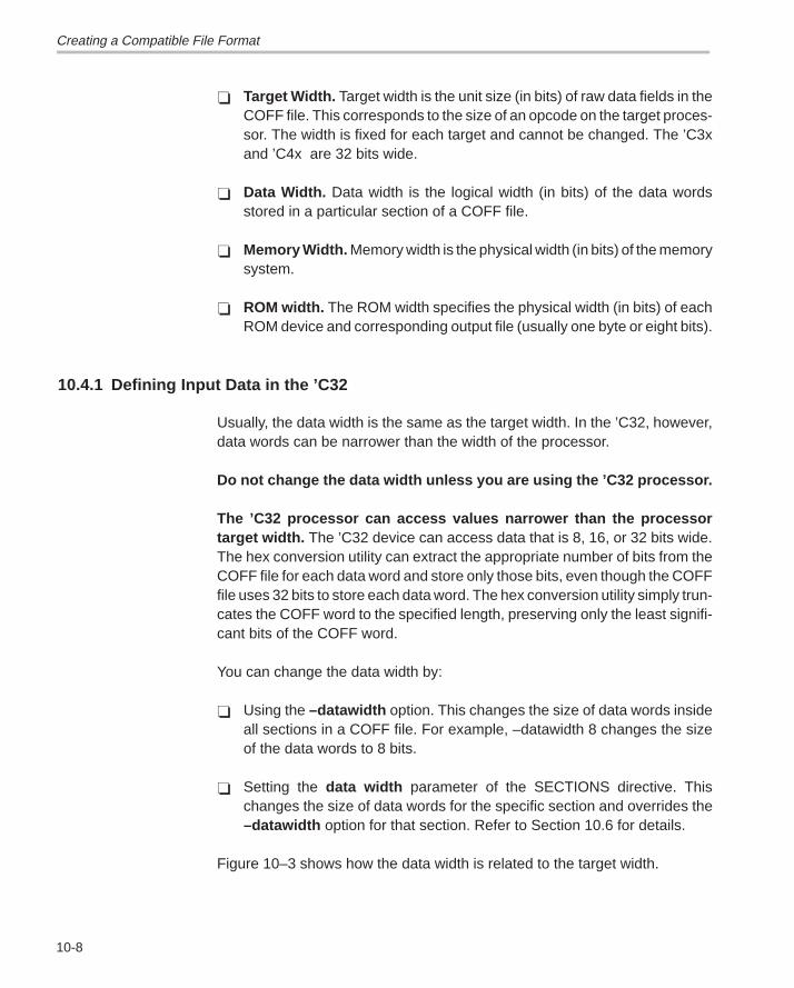
Creating a Compatible File Format
10-8
� Target Width. Target width is the unit size (in bits) of raw data fields in theCOFF file. This corresponds to the size of an opcode on the target proces-sor. The width is fixed for each target and cannot be changed. The ’C3xand ’C4x are 32 bits wide.
� Data Width. Data width is the logical width (in bits) of the data wordsstored in a particular section of a COFF file.
� Memory Width. Memory width is the physical width (in bits) of the memorysystem.
� ROM width. The ROM width specifies the physical width (in bits) of eachROM device and corresponding output file (usually one byte or eight bits).
10.4.1 Defining Input Data in the ’C32
Usually, the data width is the same as the target width. In the ’C32, however,data words can be narrower than the width of the processor.
Do not change the data width unless you are using the ’C32 processor.
The ’C32 processor can access values narrower than the processortarget width. The ’C32 device can access data that is 8, 16, or 32 bits wide.The hex conversion utility can extract the appropriate number of bits from theCOFF file for each data word and store only those bits, even though the COFFfile uses 32 bits to store each data word. The hex conversion utility simply trun-cates the COFF word to the specified length, preserving only the least signifi-cant bits of the COFF word.
You can change the data width by:
� Using the –datawidth option. This changes the size of data words insideall sections in a COFF file. For example, –datawidth 8 changes the sizeof the data words to 8 bits.
� Setting the data width parameter of the SECTIONS directive. Thischanges the size of data words for the specific section and overrides the–datawidth option for that section. Refer to Section 10.6 for details.
Figure 10–3 shows how the data width is related to the target width.
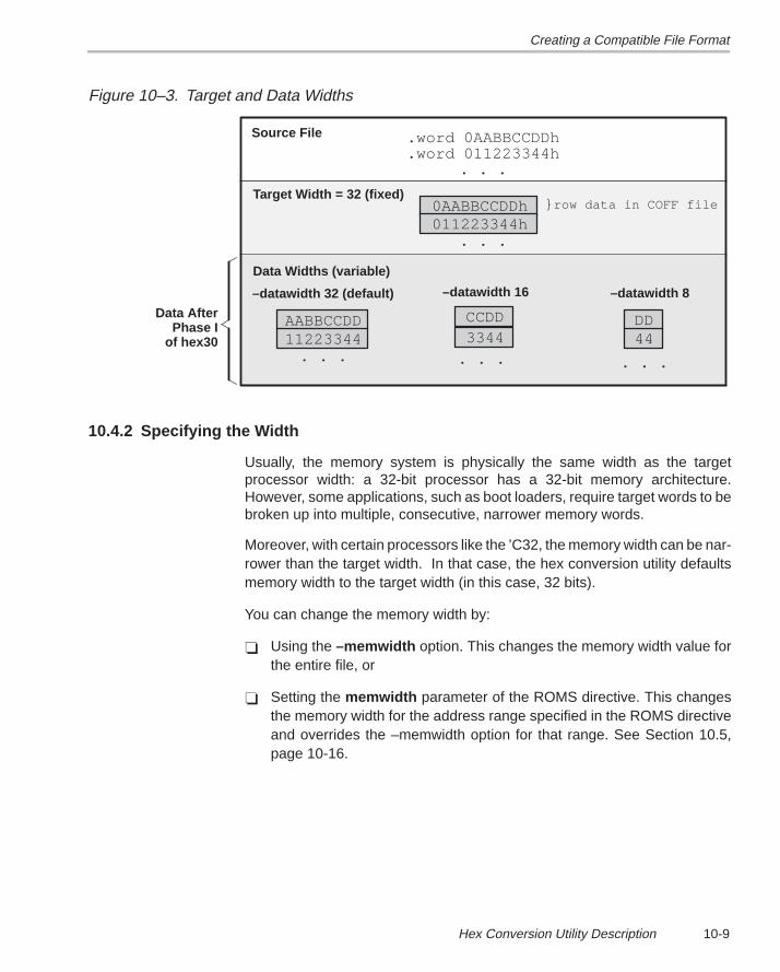
Creating a Compatible File Format
10-9Hex Conversion Utility Description
Figure 10–3. Target and Data Widths
–datawidth 32 (default)
0AABBCCDDh
AABBCCDD
Target Width = 32 (fixed)
Data Widths (variable)
Source File .word 0AABBCCDDh.word 011223344h
. . .
011223344h
11223344
. . .
. . . . . .
–datawidth 16
CCDD3344
–datawidth 8
DD44
. . .
} row data in COFF file
Data AfterPhase I
of hex30
10.4.2 Specifying the Width
Usually, the memory system is physically the same width as the targetprocessor width: a 32-bit processor has a 32-bit memory architecture.However, some applications, such as boot loaders, require target words to bebroken up into multiple, consecutive, narrower memory words.
Moreover, with certain processors like the ’C32, the memory width can be nar-rower than the target width. In that case, the hex conversion utility defaultsmemory width to the target width (in this case, 32 bits).
You can change the memory width by:
� Using the –memwidth option. This changes the memory width value forthe entire file, or
� Setting the memwidth parameter of the ROMS directive. This changesthe memory width for the address range specified in the ROMS directiveand overrides the –memwidth option for that range. See Section 10.5,page 10-16.
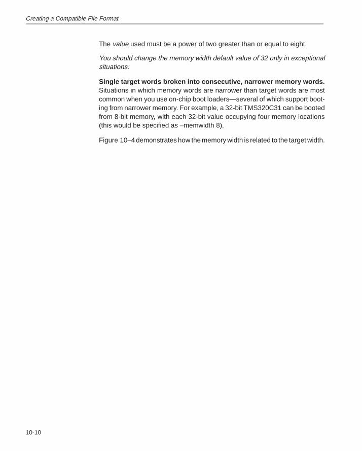
Creating a Compatible File Format
10-10
The value used must be a power of two greater than or equal to eight.
You should change the memory width default value of 32 only in exceptionalsituations:
Single target words broken into consecutive, narrower memory words.Situations in which memory words are narrower than target words are mostcommon when you use on-chip boot loaders—several of which support boot-ing from narrower memory. For example, a 32-bit TMS320C31 can be bootedfrom 8-bit memory, with each 32-bit value occupying four memory locations(this would be specified as –memwidth 8).
Figure 10–4 demonstrates how the memory width is related to the target width.
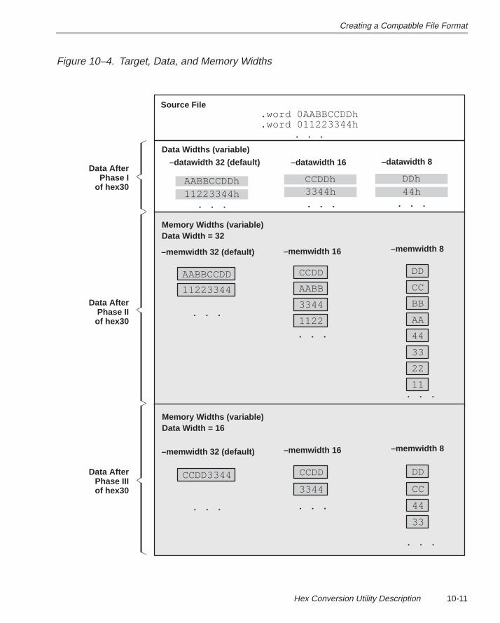
Creating a Compatible File Format
10-11Hex Conversion Utility Description
Figure 10–4. Target, Data, and Memory Widths
–memwidth 32 (default) –memwidth 16 –memwidth 8
AABBCCDDh
AABBCCDD CCDD
AA
BB
CC
DD
AABB
Data Widths (variable)
Memory Widths (variable)Data Width = 32
Source File.word 0AABBCCDDh.word 011223344h
. . .
11223344h
11223344
3344
1122
11
22
33
44
. . .
. . .
. . .
. . .
–datawidth 32 (default) –datawidth 16 –datawidth 8
CCDDh DDh3344h. . .
44h. . .
–memwidth 32 (default) –memwidth 16 –memwidth 8
CCDD3344 CCDD
CC
DD
Memory Widths (variable)Data Width = 16
3344
33
44. . . . . .
. . .
Data AfterPhase I
of hex30
Data AfterPhase IIof hex30
Data AfterPhase IIIof hex30
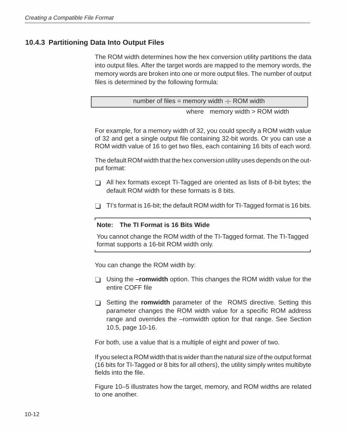
Creating a Compatible File Format
10-12
10.4.3 Partitioning Data Into Output Files
The ROM width determines how the hex conversion utility partitions the datainto output files. After the target words are mapped to the memory words, thememory words are broken into one or more output files. The number of outputfiles is determined by the following formula:
number of files = memory width � ROM width
where memory width > ROM width
For example, for a memory width of 32, you could specify a ROM width valueof 32 and get a single output file containing 32-bit words. Or you can use aROM width value of 16 to get two files, each containing 16 bits of each word.
The default ROM width that the hex conversion utility uses depends on the out-put format:
� All hex formats except TI-Tagged are oriented as lists of 8-bit bytes; thedefault ROM width for these formats is 8 bits.
� TI’s format is 16-bit; the default ROM width for TI-Tagged format is 16 bits.
Note: The TI Format is 16 Bits Wide
You cannot change the ROM width of the TI-Tagged format. The TI-Taggedformat supports a 16-bit ROM width only.
You can change the ROM width by:
� Using the –romwidth option. This changes the ROM width value for theentire COFF file
� Setting the romwidth parameter of the ROMS directive. Setting thisparameter changes the ROM width value for a specific ROM addressrange and overrides the –romwidth option for that range. See Section10.5, page 10-16.
For both, use a value that is a multiple of eight and power of two.
If you select a ROM width that is wider than the natural size of the output format(16 bits for TI-Tagged or 8 bits for all others), the utility simply writes multibytefields into the file.
Figure 10–5 illustrates how the target, memory, and ROM widths are relatedto one another.
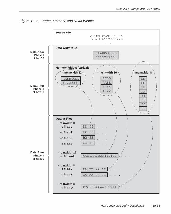
Creating a Compatible File Format
10-13Hex Conversion Utility Description
Figure 10–5. Target, Memory, and ROM Widths
–memwidth 32 –memwidth 16 –memwidth 8
0AABBCCDDh
AABBCCDD CCDD
AABBCCDD
AABB
Data Width = 32
Memory Widths (variable)
Source File.word 0AABBCCDDh.word 011223344h
. . .
011223344h
1122334433441122
11223344
Output Files
–romwidth 8
–romwidth 16
–romwidth 8
–romwidth 8
–o file.b0
–o file.b1
–o file.b2
–o file.b3
CC 33
BB 22
DD 44
AA 11
–o file.wrd CCDDAABB33441122
–o file.b0
–o file.b1 CC AA 33 11
DD BB 44 22
–o file.byt DDCCBBAA44332211
. . .
. . .
. . .
. . .
. . .
. . .
. . .
. . .
. . .
. . .
. . .
. . .
Data AfterPhase I
of hex30
Data AfterPhase IIof hex30
Data AfterPhaseIIIof hex30
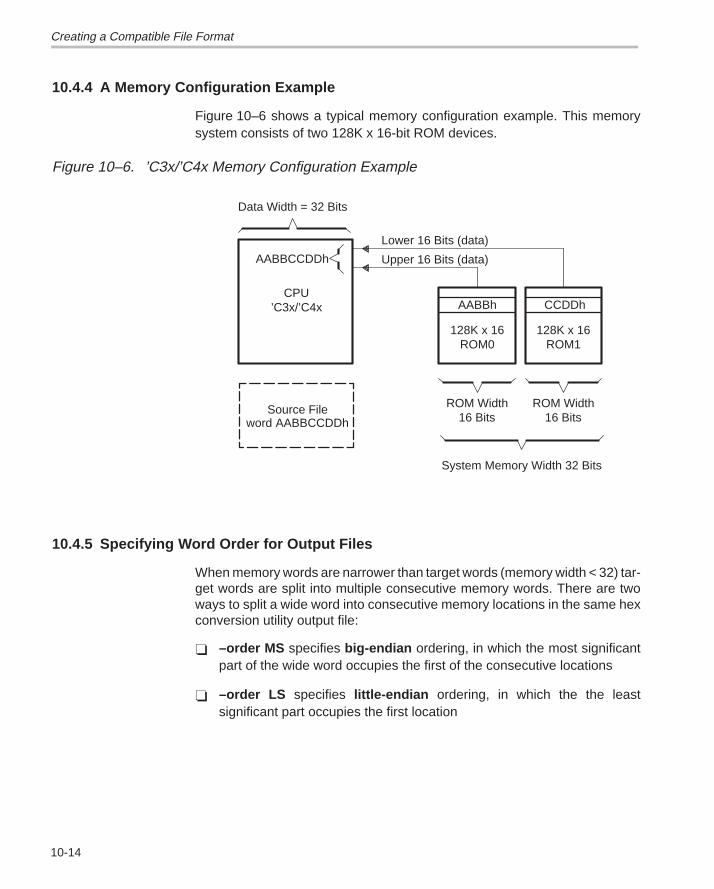
Creating a Compatible File Format
10-14
10.4.4 A Memory Configuration Example
Figure 10–6 shows a typical memory configuration example. This memorysystem consists of two 128K x 16-bit ROM devices.
Figure 10–6. ’C3x/’C4x Memory Configuration Example
Upper 16 Bits (data)
Lower 16 Bits (data)
System Memory Width 32 Bits
ROM Width16 Bits16 Bits
ROM Width
ROM1128K x 16
ROM0128K x 16
’C3x/’C4xCPU
Source Fileword AABBCCDDh
AABBCCDDh
AABBh CCDDh
Data Width = 32 Bits
10.4.5 Specifying Word Order for Output Files
When memory words are narrower than target words (memory width < 32) tar-get words are split into multiple consecutive memory words. There are twoways to split a wide word into consecutive memory locations in the same hexconversion utility output file:
� –order MS specifies big-endian ordering, in which the most significantpart of the wide word occupies the first of the consecutive locations
� –order LS specifies little-endian ordering, in which the the leastsignificant part occupies the first location
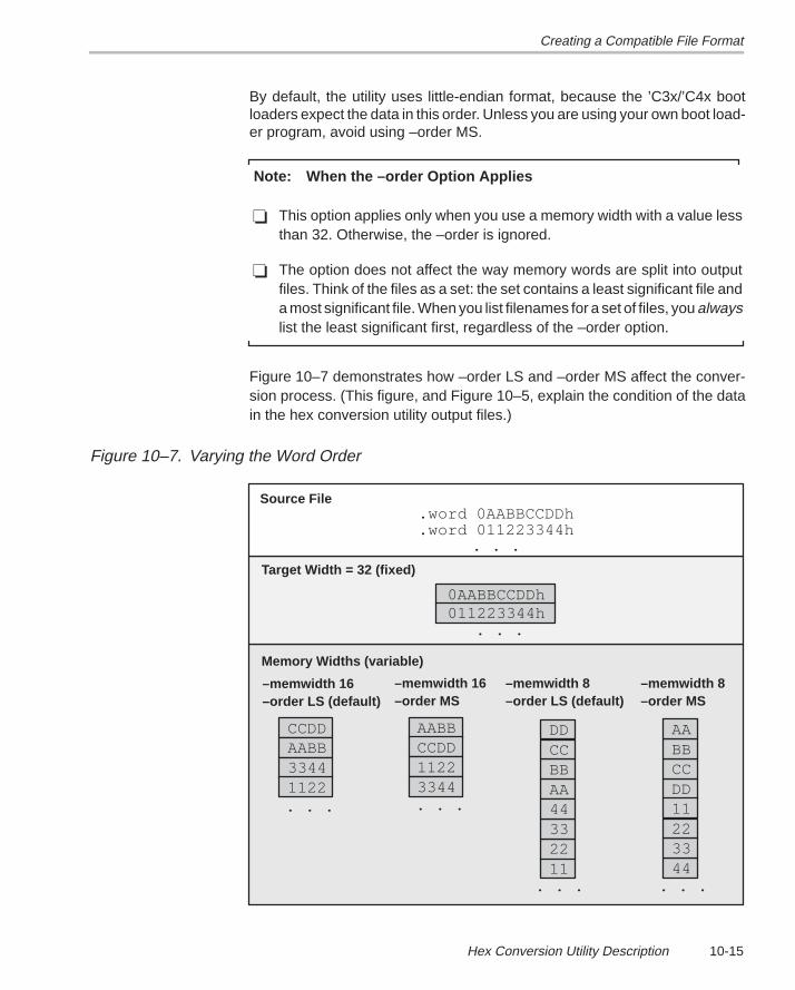
Creating a Compatible File Format
10-15Hex Conversion Utility Description
By default, the utility uses little-endian format, because the ’C3x/’C4x bootloaders expect the data in this order. Unless you are using your own boot load-er program, avoid using –order MS.
Note: When the –order Option Applies
� This option applies only when you use a memory width with a value lessthan 32. Otherwise, the –order is ignored.
� The option does not affect the way memory words are split into outputfiles. Think of the files as a set: the set contains a least significant file anda most significant file. When you list filenames for a set of files, you alwayslist the least significant first, regardless of the –order option.
Figure 10–7 demonstrates how –order LS and –order MS affect the conver-sion process. (This figure, and Figure 10–5, explain the condition of the datain the hex conversion utility output files.)
Figure 10–7. Varying the Word Order
0AABBCCDDh
Target Width = 32 (fixed)
Memory Widths (variable)
Source File.word 0AABBCCDDh.word 011223344h
. . .
011223344h. . .
. . .
. . .
–memwidth 16–order LS (default)
CCDDAABB33441122
–memwidth 16–order MS
AABBCCDD11223344. . .
. . .
–memwidth 8–order LS (default)
AABBCCDD
11223344
–memwidth 8–order MS
DDCCBBAA
44332211
Using the ROMS Directive to Specify Memory Configuration
10-16
10.5 Using the ROMS Directive to Specify Memory Configuration
The ROMS directive specifies the physical memory configuration of yoursystem as a list of address-range parameters.
Each address range will produce one set of files containing the hex conversionutility output data corresponding to that address range. Each file will then beused to program a single ROM device.
The ROMS directive is similar to the MEMORY directive of the TMS320 linker:both define the memory map of the target address space. Each line entry inthe ROMS directive defines a specific address range. The general syntax is:
ROMS{
[PAGE n:]romname: [origin =value,] [length =value,] [romwidth =value,]
[memwidth =value,] [fill =value,][files ={filename1, filename2, ...}]
romname: [origin =value,] [length =value,] [romwidth =value,][memwidth =value,] [fill =value,][files ={filename1, filename2, ...}]
...}
ROMS begins the directive definition.
PAGE identifies a memory space for processors that use multipleaddress spaces or memory overlay pages. Each memoryrange you define after the PAGE command belongs to thatpage until you specify another page. If you don’t include PAGE,all ranges belong to page 0. Note that the ’C3x/’C4x processorsdo not offer multiple address spaces.
romname identifies a memory range. The name of the memory rangemay be one to eight characters in length. The name has nosignificance to the program; it simply identifies the range. (Du-plicate memory range names are allowed.)
origin specifies the starting address of a memory range. It may betyped as origin, org, or o. The associated value must be adecimal, octal, or hexadecimal constant. If you omit the originvalue, the origin defaults to 0.
Using the ROMS Directive to Specify Memory Configuration
10-17Hex Conversion Utility Description
The following table summarizes the notation you can use to specify a decimal,octal, or hexadecimal constant:
Constant Notation Example
Hexadecimal 0x prefix or h suffix 0x77 or 077h
Octal 0 prefix 077
Decimal No prefix or suffix 77
length specifies the length of a memory range as a physical length ofthe ROM device. It may be entered as length, len, or l. The val-ue must be a decimal, octal, or hexadecimal constant. If youomit the length value, it defaults to fill the rest of the addressspace.
romwidth specifies the physical ROM width of this range in bits (see page10-12). Any value you specify here overrides the –romwidth op-tion. The value must be a decimal, octal, or hexadecimalconstant that is a power of two greater than or equal to eight.
memwidth specifies the memory width of this range in bits (see page10-9). Any value you specify here overrides the –memwidthoption. The value must be a decimal, octal, or hexadecimalconstant that is a power of two greater than or equal to eight.When using –memwidth, you must also specify the paddr pa-rameter for each section in the SECTIONS directive.
fill specifies a fill value to use for this range. In image mode, thehex conversion utility uses this value to fill any holes betweensections in a range. The value must be a decimal, octal, orhexadecimal constant with a width equal to the target width.Any value you specify here overrides the –fill option. [You mustalso use the –image option when using fill.] See page 10-26.
files identify the names of the output files that correspond to thisrange. Enclose the list of names in curly braces and order themfrom least significant to most significant output file.
The number of file names should equal the number of outputfiles that the range will generate. The utility warns you if you listtoo many or too few filenames.
Unless you are using the –image option, all of the parameters defining a rangeare optional. A range with no origin or length defines the entire address space.In image mode, an origin and length are required for all ranges. The commasand equals signs are also optional.
Ranges on the same page must not overlap and must be listed in order ofascending address.
Using the ROMS Directive to Specify Memory Configuration
10-18
10.5.1 When to Use the ROMS Directive
If you don’t use a ROMS directive, the utility defines a single default range thatincludes the entire program address space (PAGE 0). This is equivalent to aROMS directive with a single range without origin or length.
Use the ROMS Directive when you want to:
� Program large amounts of data into fixed-size ROMs . When you speci-fy memory ranges corresponding to the length of your ROMs, the utility au-tomatically breaks the output into blocks that fit into the ROMs.
� Restrict output to certain segments . You can also use the ROMS direc-tive to restrict the conversion to a certain segment or segments of the tar-get address space. The utility does not convert the data that falls outsideof the ranges defined by the ROMS directive. Sections can span rangeboundaries; the utility splits them at the boundary into multiple ranges. Ifa section falls completely outside any of the ranges you define, the utilitydoes not convert that section and issues no messages or warnings. In thisway, you can exclude sections without listing them by name with theSECTIONS directive. However, if a section falls partially in a range andpartially in unconfigured memory, the utility issues a warning and convertsonly the part within the range.
� Use the –image option. When you use this option, you must use a ROMSdirective. Each range is filled completely so that each output file in a rangecontains data for the whole range. Gaps before, between or after sectionsare filled with the fill value from the ROMS directive, with the value speci-fied with the –fill option, or with the default value of zero.
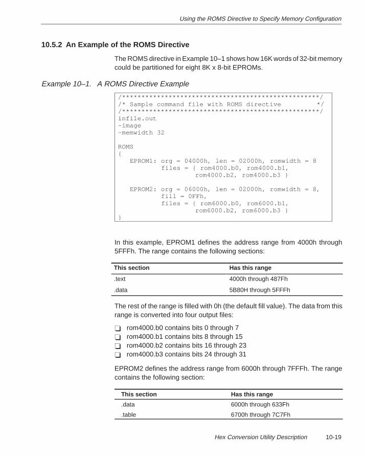
Using the ROMS Directive to Specify Memory Configuration
10-19Hex Conversion Utility Description
10.5.2 An Example of the ROMS Directive
The ROMS directive in Example 10–1 shows how 16K words of 32-bit memorycould be partitioned for eight 8K x 8-bit EPROMs.
Example 10–1. A ROMS Directive Example
/***************************************************//* Sample command file with ROMS directive *//***************************************************/infile.out–image–memwidth 32
ROMS{ EPROM1: org = 04000h, len = 02000h, romwidth = 8 files = { rom4000.b0, rom4000.b1,
rom4000.b2, rom4000.b3 }
EPROM2: org = 06000h, len = 02000h, romwidth = 8, fill = 0FFh, files = { rom6000.b0, rom6000.b1,
rom6000.b2, rom6000.b3 }}
In this example, EPROM1 defines the address range from 4000h through5FFFh. The range contains the following sections:
This section Has this range
.text 4000h through 487Fh
.data 5B80H through 5FFFh
The rest of the range is filled with 0h (the default fill value). The data from thisrange is converted into four output files:
� rom4000.b0 contains bits 0 through 7� rom4000.b1 contains bits 8 through 15� rom4000.b2 contains bits 16 through 23� rom4000.b3 contains bits 24 through 31
EPROM2 defines the address range from 6000h through 7FFFh. The rangecontains the following section:
This section Has this range
.data 6000h through 633Fh
.table 6700h through 7C7Fh
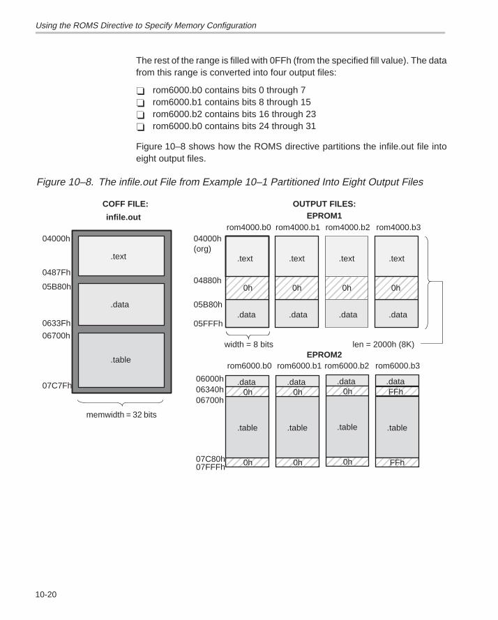
Using the ROMS Directive to Specify Memory Configuration
10-20
The rest of the range is filled with 0FFh (from the specified fill value). The datafrom this range is converted into four output files:
� rom6000.b0 contains bits 0 through 7� rom6000.b1 contains bits 8 through 15� rom6000.b2 contains bits 16 through 23� rom6000.b0 contains bits 24 through 31
Figure 10–8 shows how the ROMS directive partitions the infile.out file intoeight output files.
Figure 10–8. The infile.out File from Example 10–1 Partitioned Into Eight Output Files
ÉÉÉÉ
rom4000.b0
rom6000.b0
rom4000.b1
rom6000.b1
04000h(org)
06000h
.text
.data
.table
.text .text
.data .data
.table
.data
0h
infile.out
memwidth = 32 bits
ÉÉÉÉÉÉÉÉÉÉÉÉ
0hÉÉÉÉÉÉÉÉÉÉÉÉ
0h
0Fh
04000h
0487Fh
05B80h
0633Fh
06700h
07C7Fh
04880h
05B80h
06340h06700h
07C80h07FFFh
EPROM1
EPROM2
05FFFh
ÉÉÉÉÉÉÉÉ
0h
rom4000.b2
.text
.data
ÉÉÉÉÉÉÉÉÉÉÉÉ
0h
rom4000.b3
.text
.data
ÉÉÉÉÉÉÉÉÉÉÉÉ
0h
OUTPUT FILES:COFF FILE:
.dataÉÉÉÉFFh
.table
ÉÉÉÉFFh
rom6000.b3rom6000.b2
width = 8 bits len = 2000h (8K)
ÉÉÉÉ
.table
.data
0h
0FhÉÉÉÉÉÉÉÉ
0h
ÉÉÉÉ
.table
.data
0h
0FhÉÉÉÉ0h
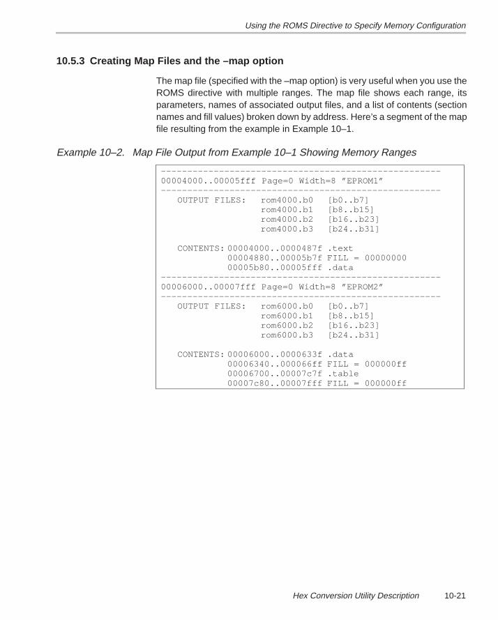
Using the ROMS Directive to Specify Memory Configuration
10-21Hex Conversion Utility Description
10.5.3 Creating Map Files and the –map option
The map file (specified with the –map option) is very useful when you use theROMS directive with multiple ranges. The map file shows each range, itsparameters, names of associated output files, and a list of contents (sectionnames and fill values) broken down by address. Here’s a segment of the mapfile resulting from the example in Example 10–1.
Example 10–2. Map File Output from Example 10–1 Showing Memory Ranges
–––––––––––––––––––––––––––––––––––––––––––––––––––––00004000..00005fff Page=0 Width=8 ”EPROM1”–––––––––––––––––––––––––––––––––––––––––––––––––––––
OUTPUT FILES: rom4000.b0 [b0..b7]rom4000.b1 [b8..b15]rom4000.b2 [b16..b23]rom4000.b3 [b24..b31]
CONTENTS: 00004000..0000487f .text00004880..00005b7f FILL = 0000000000005b80..00005fff .data
–––––––––––––––––––––––––––––––––––––––––––––––––––––00006000..00007fff Page=0 Width=8 ”EPROM2”–––––––––––––––––––––––––––––––––––––––––––––––––––––
OUTPUT FILES: rom6000.b0 [b0..b7]rom6000.b1 [b8..b15]rom6000.b2 [b16..b23]rom6000.b3 [b24..b31]
CONTENTS: 00006000..0000633f .data00006340..000066ff FILL = 000000ff00006700..00007c7f .table00007c80..00007fff FILL = 000000ff
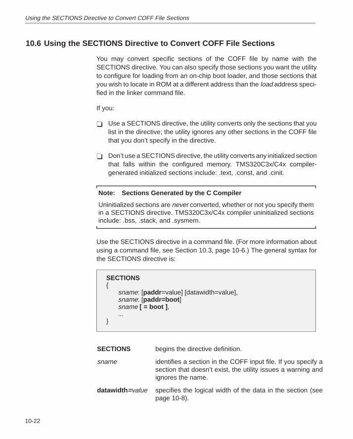
Using the SECTIONS Directive to Convert COFF File Sections
10-22
10.6 Using the SECTIONS Directive to Convert COFF File Sections
You may convert specific sections of the COFF file by name with theSECTIONS directive. You can also specify those sections you want the utilityto configure for loading from an on-chip boot loader, and those sections thatyou wish to locate in ROM at a different address than the load address speci-fied in the linker command file.
If you:
� Use a SECTIONS directive, the utility converts only the sections that youlist in the directive; the utility ignores any other sections in the COFF filethat you don’t specify in the directive.
� Don’t use a SECTIONS directive, the utility converts any initialized sectionthat falls within the configured memory. TMS320C3x/C4x compiler-generated initialized sections include: .text, .const, and .cinit.
Note: Sections Generated by the C Compiler
Uninitialized sections are never converted, whether or not you specify themin a SECTIONS directive. TMS320C3x/C4x compiler uninitialized sectionsinclude: .bss, .stack, and .sysmem.
Use the SECTIONS directive in a command file. (For more information aboutusing a command file, see Section 10.3, page 10-6.) The general syntax forthe SECTIONS directive is:
SECTIONS{
sname: [paddr =value] [datawidth=value],sname: [paddr=boot ]sname [ = boot ] ,...
}
SECTIONS begins the directive definition.
sname identifies a section in the COFF input file. If you specify asection that doesn’t exist, the utility issues a warning andignores the name.
datawidth =value specifies the logical width of the data in the section (seepage 10-8).
Using the SECTIONS Directive to Convert COFF File Sections
10-23Hex Conversion Utility Description
paddr =value specifies the physical ROM address at which this sectionshould be located. This value overrides the section load ad-dress given by the linker. (Refer to Section 10.10).This val-ue must be a decimal, octal, or hexadecimal constant; it canalso be the word boot to indicate a boot table section for usewith the on-chip boot loader. [Boot sections have a physicaladdress determined both by the target processor type andby the various boot-loader-specific command line options.]If your file contains multiple sections, and if one sectionuses a –paddr option, then all sections must use a –paddroption.
= boot configures a section for loading by the on-chip boot loader.This is equivalent to using paddr=boot.
The commas are optional. For more similarity with the linker’s SECTIONSdirective, you can use colons after the section names and in place of the equalssign on the boot keyboard. For example,
SECTIONS { .text: .data: boot }
SECTIONS { .text, .data = boot }
are equivalent.
For example, suppose a COFF file contains six initialized sections: .text, .data,.const, .vectors, .coeff, and .tables. If you want only .text and .data to be con-verted, use a SECTIONS directive to specify this:
SECTIONS { .text, .data }
To configure both of these sections for boot loading, add the boot keyword:
SECTIONS { .text = boot, .data = boot }
Note: Using the –boot Option and the SECTIONS Directive
When you use the SECTIONS directive with the on-chip boot loader, notethat the –boot option is ignored. You must explicitly specify any boot sectionsin the SECTIONS directive. For more information about –boot and othercommand line options associated with the on-chip boot loader, seeTable 10–2, Boot Loader Utility Options, page 10-29.
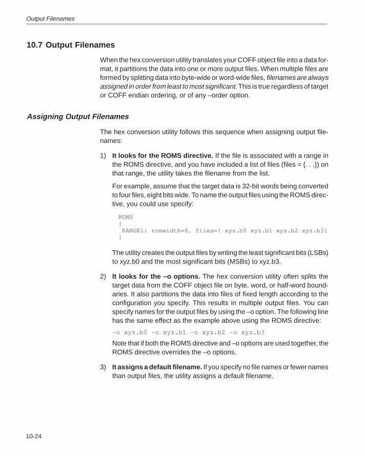
Output Filenames
10-24
10.7 Output Filenames
When the hex conversion utility translates your COFF object file into a data for-mat, it partitions the data into one or more output files. When multiple files areformed by splitting data into byte-wide or word-wide files, filenames are alwaysassigned in order from least to most significant. This is true regardless of targetor COFF endian ordering, or of any –order option.
Assigning Output Filenames
The hex conversion utility follows this sequence when assigning output file-names:
1) It looks for the ROMS directive. If the file is associated with a range inthe ROMS directive, and you have included a list of files (files = {. . .}) onthat range, the utility takes the filename from the list.
For example, assume that the target data is 32-bit words being convertedto four files, eight bits wide. To name the output files using the ROMS direc-tive, you could use specify:
ROMS{ RANGE1: romwidth=8, files={ xyz.b0 xyz.b1 xyz.b2 xyz.b3}}
The utility creates the output files by writing the least significant bits (LSBs)to xyz.b0 and the most significant bits (MSBs) to xyz.b3.
2) It looks for the –o options. The hex conversion utility often splits thetarget data from the COFF object file on byte, word, or half-word bound-aries. It also partitions the data into files of fixed length according to theconfiguration you specify. This results in multiple output files. You canspecify names for the output files by using the –o option. The following linehas the same effect as the example above using the ROMS directive:
–o xyz.b0 –o xyz.b1 –o xyz.b2 –o xyz.b3
Note that if both the ROMS directive and –o options are used together, theROMS directive overrides the –o options.
3) It assigns a default filename. If you specify no file names or fewer namesthan output files, the utility assigns a default filename.
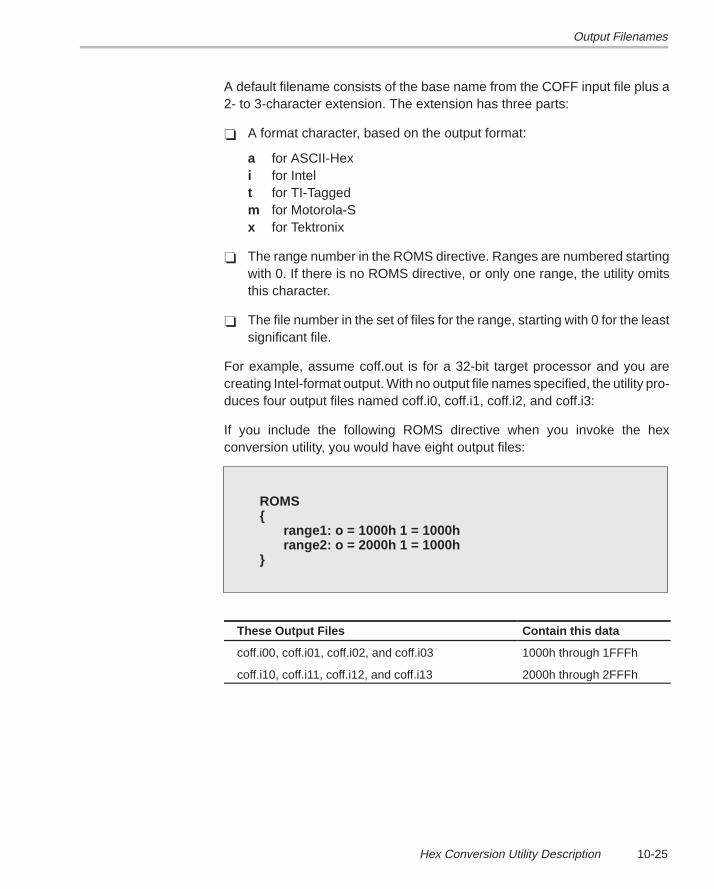
Output Filenames
10-25Hex Conversion Utility Description
A default filename consists of the base name from the COFF input file plus a2- to 3-character extension. The extension has three parts:
� A format character, based on the output format:
a for ASCII-Hexi for Intelt for TI-Taggedm for Motorola-Sx for Tektronix
� The range number in the ROMS directive. Ranges are numbered startingwith 0. If there is no ROMS directive, or only one range, the utility omitsthis character.
� The file number in the set of files for the range, starting with 0 for the leastsignificant file.
For example, assume coff.out is for a 32-bit target processor and you arecreating Intel-format output. With no output file names specified, the utility pro-duces four output files named coff.i0, coff.i1, coff.i2, and coff.i3:
If you include the following ROMS directive when you invoke the hexconversion utility, you would have eight output files:
ROMS{
range1: o = 1000h 1 = 1000hrange2: o = 2000h 1 = 1000h
}
These Output Files Contain this data
coff.i00, coff.i01, coff.i02, and coff.i03 1000h through 1FFFh
coff.i10, coff.i11, coff.i12, and coff.i13 2000h through 2FFFh
Image Mode and the –fill Option
10-26
10.8 Image Mode and the –fill Option
This section explains the advantages of operating in image mode, and detailsthe method of producing output files with a precise, continuous image of atarget memory range.
10.8.1 The –image Option
With the –image option, the utility generates a memory image by completelyfilling all of the mapped ranges specified in the ROMS directive.
A COFF file consists of blocks of memory (sections) with assigned memorylocations. Typically, all sections are not adjacent: there are gaps betweensections in the address space for which there is no data. When such a file isconverted without the use of image mode, the hex conversion utility bridgesthese gaps by using the address records in the output file to skip ahead to thestart of the next section. In other words, there may be discontinuities in the out-put file addresses. Some EPROM programmers do not support address dis-continuities.
In image mode, there are no discontinuities. Each output file contains acontinuous stream of data that corresponds exactly to an address range in tar-get memory. Any gaps before, between, or after sections are filled with a fillvalue that you supply.
An output file converted by using image mode still has address recordsbecause many of the hex formats require an address on each line. However,in image mode, these addresses will always be contiguous.
Note: Defining the Ranges of Target Memory
If you use image mode, you must also use a ROMS directive. In image mode,each output file corresponds directly to a range of target memory. You mustdefine the ranges. If you don’t supply the ranges of target memory, the utilitytries to build a memory image of the entire target processor addressspace—potentially a huge amount of output data. To prevent this situation,the utility requires you to explicitly restrict the address space with the ROMSdirective.
Image Mode and the –fill Option
10-27Hex Conversion Utility Description
10.8.2 Specifying a Fill Value
The –fill option specifies a value for filling the holes between sections. The fillvalue must be specified as an integer constant following the –fill option. Thewidth of the constant is assumed to be that of a word on the target processor.For example, on the ’C3x, specifying –fill 0FFFFh results in a fill pattern of0000FFFFh. The constant value is not sign-extended.
Note: If You Do Not Specify A Value With The Fill Option
The hex conversion utility uses a default fill value of 0 if you don’t specify avalue with the fill option. The –fill option is valid only when you use –image;otherwise it is ignored.
10.8.3 Steps to Follow in Image Mode
Step 1: Define the ranges of target memory with a ROMS directive (seeSection 10.5).
Step 2: Invoke the hex conversion utility with the –image option. You can op-tionally use the –byte option to number the bytes sequentially andthe –zero option to reset the address origin to zero for each outputfile. If you don’t specify a fill value with the ROMS directive and youwant a value other than the default, use the –fill option.
Building a Boot-Table From an On-Chip Boot Loader
10-28
10.9 Building a Boot-Table From an On-Chip Boot Loader
Some DSP devices such as the ’C31, ’C32, and ’C4x have a built-in bootloader that initializes memory with one or more blocks of code or data. Theboot loader uses a special table (a boot table) stored in memory (such asEPROM) or loaded from a device peripheral (such as a serial or communica-tions port) to initialize the code or data. The hex conversion utility supports theboot loader by automatically building the boot table.
10.9.1 Description of the Boot Table
The input for a boot loader is called the boot table (also known as a sourceprogram). The boot table contains records that instruct the on-chip loader tocopy blocks of data contained in the table to specified destination addresses.Some boot tables also contain values for initializing various processor controlregisters. The boot table can be stored in memory or read in through a deviceperipheral.
The hex conversion utility automatically builds the boot table for the boot load-er. Using the utility, you specify the COFF sections you want the boot loaderto initialize, the table location, and the values for any control registers. The hexconversion utility identifies the target device type from the COFF file, builds acomplete image of the table according to the format required by that device,and converts it into hexadecimal in the output files. Then, you can burn thetable into ROM or load it by other means.
Boot loaders support loading from memory that is narrower than the normalwidth of memory. For example, you can boot a 32-bit TMS320C31,TMS320C32, or TMS320C40 from a single eight-bit EPROM by using the –memwidth option to configure the width of the boot table. The hex conversionutility automatically adjusts the table’s format and length.
10.9.2 The Boot Table Format
The boot table format includes a header record containing the width of thetable and possibly some values for various control registers. Each subsequentblock has a header containing the size and destination address of the blockfollowed by data for the block. Multiple blocks can be entered; a terminationblock follows the last block. Finally, the table can have a footer containing morecontrol register values. Refer to the boot-loader section in the specific deviceuser’s guide for more information.
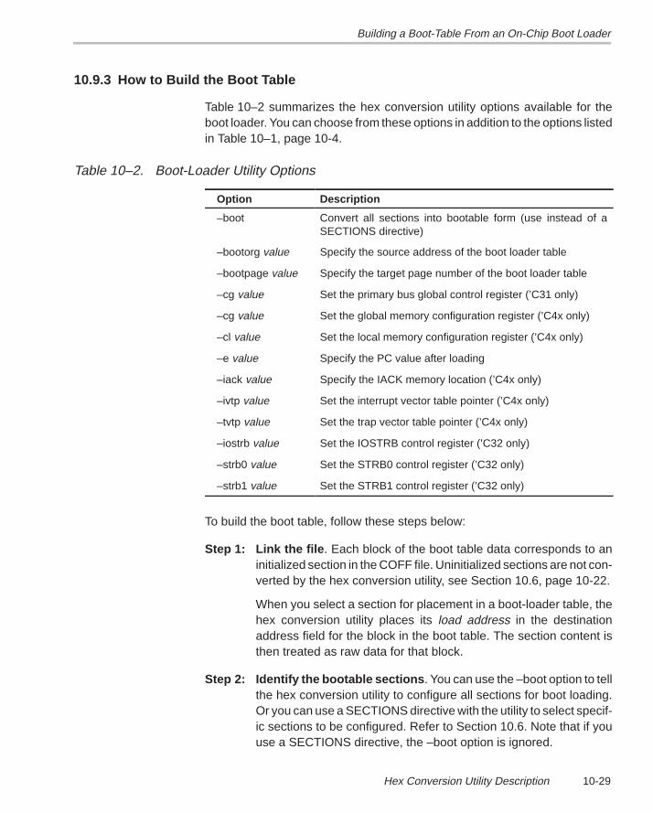
Building a Boot-Table From an On-Chip Boot Loader
10-29Hex Conversion Utility Description
10.9.3 How to Build the Boot Table
Table 10–2 summarizes the hex conversion utility options available for theboot loader. You can choose from these options in addition to the options listedin Table 10–1, page 10-4.
Table 10–2. Boot-Loader Utility Options
Option Description
–boot Convert all sections into bootable form (use instead of aSECTIONS directive)
–bootorg value Specify the source address of the boot loader table
–bootpage value Specify the target page number of the boot loader table
–cg value Set the primary bus global control register (’C31 only)
–cg value Set the global memory configuration register (’C4x only)
–cl value Set the local memory configuration register (’C4x only)
–e value Specify the PC value after loading
–iack value Specify the IACK memory location (’C4x only)
–ivtp value Set the interrupt vector table pointer (’C4x only)
–tvtp value Set the trap vector table pointer (’C4x only)
–iostrb value Set the IOSTRB control register (’C32 only)
–strb0 value Set the STRB0 control register (’C32 only)
–strb1 value Set the STRB1 control register (’C32 only)
To build the boot table, follow these steps below:
Step 1: Link the file . Each block of the boot table data corresponds to aninitialized section in the COFF file. Uninitialized sections are not con-verted by the hex conversion utility, see Section 10.6, page 10-22.
When you select a section for placement in a boot-loader table, thehex conversion utility places its load address in the destinationaddress field for the block in the boot table. The section content isthen treated as raw data for that block.
Step 2: Identify the bootable sections . You can use the –boot option to tellthe hex conversion utility to configure all sections for boot loading.Or you can use a SECTIONS directive with the utility to select specif-ic sections to be configured. Refer to Section 10.6. Note that if youuse a SECTIONS directive, the –boot option is ignored.
Building a Boot-Table From an On-Chip Boot Loader
10-30
Step 3: Set the ROM address of the boot table . Use the –bootorg optionto set the source address of the complete table. For example, if youare using the ’C4x and booting from memory location 40000000h,specify –bootorg 40000000h. The address field in the the hexconversion utility output file will then start at 4000000h.
If you use –bootorg SERIAL or –bootorg COMM, or if you do not usethe –bootorg option at all, the utility places the table at the origin ofthe first memory range in a ROMS directive. If you do not use aROMS directive, the table will start at the first section load address.There is also a –bootpage option for starting the table somewhereother than page 0.
Step 4: Set boot-loader-specific options , such as entry point, memorycontrol registers, as needed.
Step 5: Describe your system memory configuration . Refer to Section10.4, page 10-7, and Section 10.5, page 10-16 for details.
The complete boot table is similar to a single section containing all of the head-er records and data for the boot loader. The address of this “section” is the boottable origin. As part of the normal conversion process, the hex conversion util-ity converts the boot table to hexadecimal format and maps it into the outputfiles like any other section.
Be sure to leave room in the memory map for the boot table, especially whenyou are using the ROMS directive. The boot table cannot overlap other non-boot sections or unconfigured memory. Usually, this is not a problem; typically,a portion of memory in your system is reserved for the boot table. Simply con-figure this memory as one or more ranges in the ROMS directive, and use the–bootorg option to specify the starting address.
Building a Boot-Table From an On-Chip Boot Loader
10-31Hex Conversion Utility Description
10.9.4 Booting From a Device Peripheral
You can choose to boot from a serial or other port by using the SERIAL orCOMM keyword with the –bootorg option. Your selection of a keyword de-pends on the target device and the channel you want to use. For example, toboot a ’C31 or ’C32 from its serial port, specify –bootorg SERIAL on thecommand line or in a command file. To boot a TMS320C4x from one of its com-munication ports, specify –bootorg COMM .
Notes:
q Possible Memory Conflicts When you boot from a device peripheral,the boot table is not actually in memory; it is being received through thedevice peripheral. However, as explained in Step Three, page 10-30, amemory address is assigned.
q Why the System Might Require an EPROM Format for a PeripheralBoot Loader Address In a typical system, a parent processor boots aa child processor through that child’s peripheral. The boot loader tableitself may occupy space in the memory map of the child processor. TheEPROM format and ROMS directive address used correspond to theone used by the parent processor, not the one that is used by the child.
10.9.5 Setting the Entry Point for the Boot Table
After completing the boot load process, program execution starts at theaddress of the first block loaded (default entry point). By using the –e optionwith the hex conversion utility, you can set the entry point to a different address.
For example, if you want your program to start running at address 0123456hafter loading, specify –e 0123456h on the command line or in a command file.The value must be a constant; the hex conversion utility cannot evaluatesymbolic expressions, like c_int00 (default entry point assigned by theC compiler). You can determine the –e address by looking at the map filethat the linker generates.
When you use the –e option, the utility builds a dummy block of length 1 anddata value 0 that loads at the specified address. Your blocks follow this dummyblock. Since the dummy block is boot-loaded first, the dummy value of 0 isoverwritten by the subsequent blocks. Then, the boot loader jumps to its ad-dress after the boot load is completed.
10.9.6 Setting Control Registers
In addition to loading data into memory, some boot loaders can also initializeprocessor control registers from values in the boot table. The hex conversionutility provides special options that you can use to set the values for these reg-isters. Table 10–3 lists the control register options. Each of these optionsrequires a constant value as its argument.
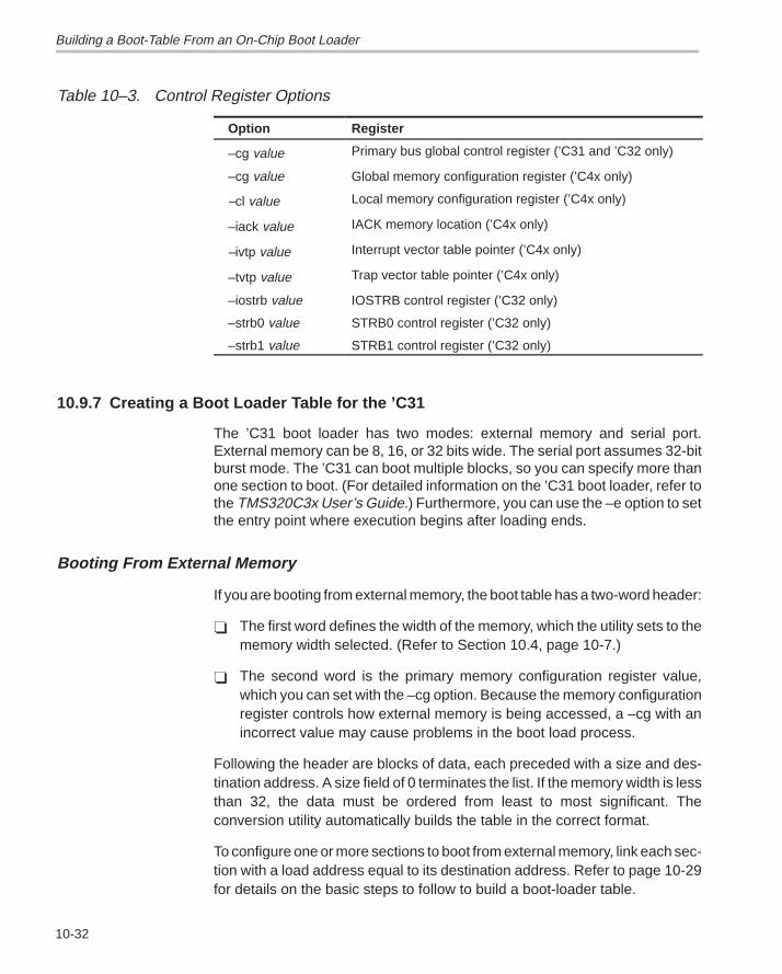
Building a Boot-Table From an On-Chip Boot Loader
10-32
Table 10–3. Control Register Options
Option Register
–cg value Primary bus global control register (’C31 and ’C32 only)
–cg value Global memory configuration register (’C4x only)
–cl value Local memory configuration register (’C4x only)
–iack value IACK memory location (’C4x only)
–ivtp value Interrupt vector table pointer (’C4x only)
–tvtp value Trap vector table pointer (’C4x only)
–iostrb value IOSTRB control register (’C32 only)
–strb0 value STRB0 control register (’C32 only)
–strb1 value STRB1 control register (’C32 only)
10.9.7 Creating a Boot Loader Table for the ’C31
The ’C31 boot loader has two modes: external memory and serial port.External memory can be 8, 16, or 32 bits wide. The serial port assumes 32-bitburst mode. The ’C31 can boot multiple blocks, so you can specify more thanone section to boot. (For detailed information on the ’C31 boot loader, refer tothe TMS320C3x User’s Guide.) Furthermore, you can use the –e option to setthe entry point where execution begins after loading ends.
Booting From External Memory
If you are booting from external memory, the boot table has a two-word header:
� The first word defines the width of the memory, which the utility sets to thememory width selected. (Refer to Section 10.4, page 10-7.)
� The second word is the primary memory configuration register value,which you can set with the –cg option. Because the memory configurationregister controls how external memory is being accessed, a –cg with anincorrect value may cause problems in the boot load process.
Following the header are blocks of data, each preceded with a size and des-tination address. A size field of 0 terminates the list. If the memory width is lessthan 32, the data must be ordered from least to most significant. Theconversion utility automatically builds the table in the correct format.
To configure one or more sections to boot from external memory, link each sec-tion with a load address equal to its destination address. Refer to page 10-29for details on the basic steps to follow to build a boot-loader table.
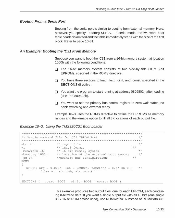
Building a Boot-Table From an On-Chip Boot Loader
10-33Hex Conversion Utility Description
Booting From a Serial Port
Booting from the serial port is similar to booting from external memory. Here,however, you specify –bootorg SERIAL. In serial mode, the two-word boottable header is omitted and the table immediately starts with the size of the firstblock. Refer to page 10-31.
An Example: Booting the ’C31 From Memory
Suppose you want to boot the ’C31 from a 16-bit memory system at location1000h with the following conditions:
� The 16-bit memory system consists of two side-by-side 8K x 8-bitEPROMs, specified in the ROMS directive.
� You have three sections to load: .text, .cinit, and .const, specified in theSECTIONS directive.
� You want the program to start running at address 0809802h after loading(use –e 0809802h).
� You want to set the primary bus control register to zero wait-states, nobank switching and external ready.
Example 10–3 uses the ROMS directive to define the EPROMs as memoryranges and the –image option to fill all 8K locations of each output file.
Example 10–3. Using the TMS320C31 Boot Loader
/***************************************************************//* Sample command file for C31 EPROM Boot *//***************************************************************/abc.out /* input file */–i /* Intel format */–memwidth 16 /* 16-bit memory system */–bootorg 1000h /* location of the external boot memory */–cg 0h /*primary bus configuration */ROMS{ EPROM: org = 01000h, len = 02000h, romwidth = 8,/* 8K x 8 */ files = { abc.lsb, abc.msb }}
SECTIONS { .text: BOOT, .cinit: BOOT, .const: BOOT }
This example produces two output files, one for each EPROM, each contain-ing 8-bit wide data. If you want a single output file with all 16 bits (one single8K x 16-bit ROM device used), use ROMwidth=16 instead of ROMwidth = 8.
Building a Boot-Table From an On-Chip Boot Loader
10-34
10.9.8 TMS320C32 Boot Loader Table Generation
The ’C32 boot loader has two modes: external memory and serial port. Exter-nal memory can be 8, 16, or 32 bits wide. The serial port assumes 32-bit burstmode. The ’C32 can boot multiple blocks, so you can specify more than onesection to boot. Furthermore, you can use the –e option to set the entry pointwhere execution begins after loading ends. For more detailed information onthe ’C32 boot loader, refer to the TMS320C3x User’s Guide and the ’C32User’s Guide.
Booting From External Memory
If you are booting from external memory, the boot table has a four-wordheader:� The first word defines the width of the memory system, which the utility
sets to the memory width selected, as explained in Section 10.4, page10-7.
� The second word is the configuration value for the IOSTRB controlregister, which you can set with the –iostrb option.
� The third word is the configuration value for the STRB0 control register,which you can set with the –strb0 option.
� The fourth word is the configuration value for the STRB1 control register,which you can set with the –strb1 option.
Following the header are blocks of data, each block preceded with a headerthat defines a size, a destination address, and a strobe-control register value.A size field of zero terminates the list. If the memory width is less than 32, thedata is ordered from least to most significant. If the data width is less than 32for any section in the boot table, only the least significant datawidth bits arestored in the output files. The conversion utility automatically builds the tablein the correct format.
To configure one or more sections to boot from external memory, link each sec-tion with a load address equal to its destination address. Refer to page 10-29for the steps required in boot-loader table generation.
If there are multiple data widths in the boot table, you can use the data widthparameter of the SECTIONS directive to specify data width, or the –datawidthoption to specify the global data width. The data width for any section con-taining code or address values must always be set to 32. Otherwise, theboot loading process may fail.
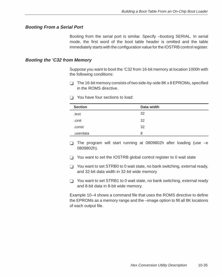
Building a Boot-Table From an On-Chip Boot Loader
10-35Hex Conversion Utility Description
Booting From a Serial Port
Booting from the serial port is similar. Specify –bootorg SERIAL. In serialmode, the first word of the boot table header is omitted and the tableimmediately starts with the configuration value for the IOSTRB control register.
Booting the ’C32 from Memory
Suppose you want to boot the ’C32 from 16-bit memory at location 1000h withthe following conditions:
� The 16-bit memory consists of two side-by-side 8K x 8 EPROMs, specifiedin the ROMS directive.
� You have four sections to load:
Section Data width
.text 32
.cinit 32
.const 32
.userdata 8
� The program will start running at 0809802h after loading (use –e0809802h).
� You want to set the IOSTRB global control register to 0 wait state
� You want to set STRB0 to 0 wait state, no bank switching, external ready,and 32-bit data width in 32-bit wide memory
� You want to set STRB1 to 0 wait state, no bank switching, external readyand 8-bit data in 8-bit wide memory.
Example 10–4 shows a command file that uses the ROMS directive to definethe EPROMs as a memory range and the –image option to fill all 8K locationsof each output file.
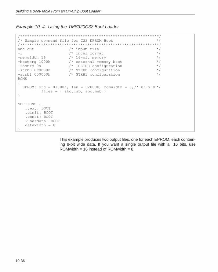
Building a Boot-Table From an On-Chip Boot Loader
10-36
Example 10–4. Using the TMS320C32 Boot Loader
/************************************************************//* Sample command file for C32 EPROM Boot *//************************************************************/abc.out /* input file */–i /* Intel format */–memwidth 16 /* 16-bit memory */–bootorg 1000h /* external memory boot */–iostrb 0h /* IOSTRB configuration */–strb0 0F0000h /* STRBO configuration */–strb1 050000h /* STRB1 configuration */ROMS{ EPROM: org = 01000h, len = 02000h, romwidth = 8,/* 8K x 8 */ files = { abc.lsb, abc.msb }}
SECTIONS { .text: BOOT.cinit: BOOT.const: BOOT .userdata: BOOTdatawidth = 8
}
This example produces two output files, one for each EPROM, each contain-ing 8-bit wide data. If you want a single output file with all 16 bits, useROMwidth = 16 instead of ROMwidth = 8.
Building a Boot-Table From an On-Chip Boot Loader
10-37Hex Conversion Utility Description
10.9.9 TMS320C4x Boot Loader Table Generation
The ’C4x boot loader can boot through either external memory or one of thecommunication ports. External memory can be 8, 16, or 32 bits wide. The com-munication ports are 8-bit channels that use internal buffering to effect 32-bittransfers. The ’C4x can boot multiple blocks, so you can specify more than onesection to boot. Furthermore, you can use the –e option to set the entry pointwhere execution begins after loading ends. Refer to the TMS320C4x User’sGuide for details on boot loader operation.
Booting From External Memory
The boot table has a three-word header:
� The first word defines the width of the memory, which the utility sets to thememory width value. See Section 10.4.
� The second and third words are the configuration values for global andlocal memory, which you can set with the –cg and –cl options, respectively.
Following the header are blocks of data, each preceded with a size and des-tination address. A size field of 0 terminates the list. Following the table arethree more configuration values for the IVTP register, TVTP register, and IACKmemory location. You can set these with the –ivtp, –tvtp, and –iack options.If the memory width is less than 32, the partial words are ordered from leastto most significant. The hex conversion utility automatically builds the table inthe correct format.
To configure one or more sections to boot from external memory, link eachsection with a load address equal to its destination address. Refer to page10-29 for the basic steps to follow when building a boot loader table. For in-formation on how to describe your external memory system, refer to Section10.7, page 10-24.
Booting From a Communications Port
Booting from a communications port is similar to booting from externalmemory. Simply specify –bootorg COMM. In comm port mode, the first wordof the boot table header (the memory width) is omitted. Refer to page 10-31for more information.
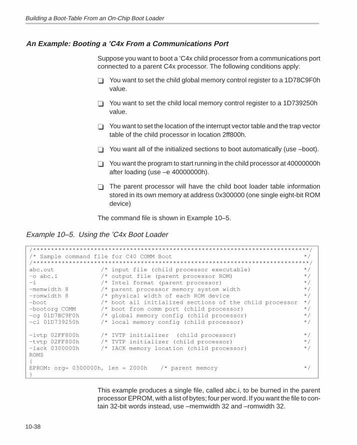
Building a Boot-Table From an On-Chip Boot Loader
10-38
An Example: Booting a ’C4x From a Communications Port
Suppose you want to boot a ’C4x child processor from a communications portconnected to a parent C4x processor. The following conditions apply:
� You want to set the child global memory control register to a 1D78C9F0hvalue.
� You want to set the child local memory control register to a 1D739250h value.
� You want to set the location of the interrupt vector table and the trap vectortable of the child processor in location 2ff800h.
� You want all of the initialized sections to boot automatically (use –boot).
� You want the program to start running in the child processor at 40000000hafter loading (use –e 40000000h).
� The parent processor will have the child boot loader table informationstored in its own memory at address 0x300000 (one single eight-bit ROMdevice)
The command file is shown in Example 10–5.
Example 10–5. Using the ’C4x Boot Loader
/*****************************************************************************//* Sample command file for C40 COMM Boot *//*****************************************************************************/abc.out /* input file (child processor executable) */–o abc.i /* output file (parent processor ROM) */–i /* Intel format (parent processor) */–memwidth 8 /* parent processor memory system width */–romwidth 8 /* physical width of each ROM device */–boot /* boot all initialized sections of the child processor */–bootorg COMM /* boot from comm port (child processor) */–cg 01D7BC9F0h /* global memory config (child processor) */–cl 01D739250h /* local memory config (child processor) */
–ivtp 02FF800h /* IVTP initializer (child processor) */–tvtp 02FF800h /* TVTP initializer (child processor) */–iack 0300000h /* IACK memory location (child processor) */ROMS{EPROM: org= 0300000h, len = 2000h /* parent memory */}
This example produces a single file, called abc.i, to be burned in the parentprocessor EPROM, with a list of bytes; four per word. If you want the file to con-tain 32-bit words instead, use –memwidth 32 and –romwidth 32.
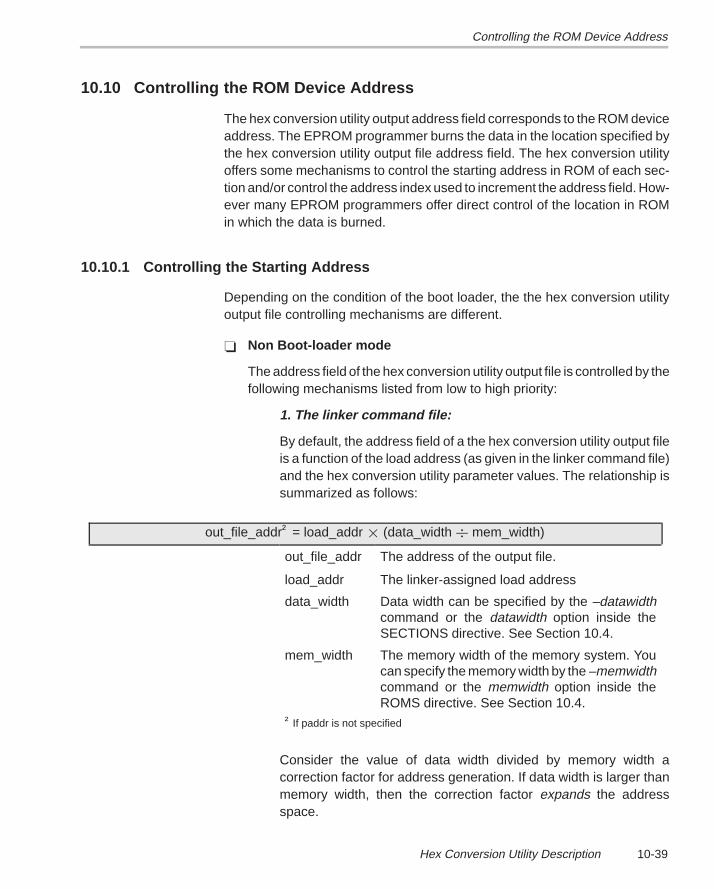
Controlling the ROM Device Address
10-39Hex Conversion Utility Description
10.10 Controlling the ROM Device Address
The hex conversion utility output address field corresponds to the ROM deviceaddress. The EPROM programmer burns the data in the location specified bythe hex conversion utility output file address field. The hex conversion utilityoffers some mechanisms to control the starting address in ROM of each sec-tion and/or control the address index used to increment the address field. How-ever many EPROM programmers offer direct control of the location in ROMin which the data is burned.
10.10.1 Controlling the Starting Address
Depending on the condition of the boot loader, the the hex conversion utilityoutput file controlling mechanisms are different.
� Non Boot-loader mode
The address field of the hex conversion utility output file is controlled by thefollowing mechanisms listed from low to high priority:
1. The linker command file:
By default, the address field of a the hex conversion utility output fileis a function of the load address (as given in the linker command file)and the hex conversion utility parameter values. The relationship issummarized as follows:
out_file_addr† = load_addr � (data_width � mem_width)
out_file_addr The address of the output file.
load_addr The linker-assigned load address
data_width Data width can be specified by the –datawidthcommand or the datawidth option inside theSECTIONS directive. See Section 10.4.
mem_width The memory width of the memory system. Youcan specify the memory width by the –memwidthcommand or the memwidth option inside theROMS directive. See Section 10.4.
† If paddr is not specified
Consider the value of data width divided by memory width acorrection factor for address generation. If data width is larger thanmemory width, then the correction factor expands the addressspace.
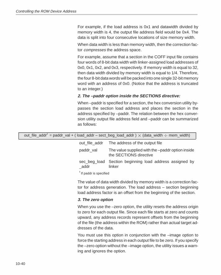
Controlling the ROM Device Address
10-40
For example, if the load address is 0x1 and datawidth divided bymemory width is 4, the output file address field would be 0x4. Thedata is split into four consecutive locations of size memory width.
When data width is less than memory width, then the correction fac-tor compresses the address space.
For example, assume that a section in the COFF input file containsfour words of 8-bit data width with linker-assigned load addresses of0x0, 0x1, 0x2, and 0x3, respectively. If memory width is equal to 32,then data width divided by memory width is equal to 1/4. Therefore,the four 8-bit data words will be packed into one single 32-bit memoryword with an address of 0x0. (Notice that the address is truncatedto an integer.)
2. The –paddr option inside the SECTIONS directive:
When –paddr is specified for a section, the hex conversion utility by-passes the section load address and places the section in theaddress specified by –paddr. The relation between the hex conver-sion utility output file address field and –paddr can be summarizedas follows:
out_file_addr† = paddr_val + ( load_addr – sect_beg_load_addr ) � (data_width � mem_width)
out_file_addr The address of the output file
paddr_val The value supplied with the –paddr option insidethe SECTIONS directive
sec_beg_load_addr
Section beginning load address assigned bylinker
†If paddr is specified
The value of data width divided by memory width is a correction fac-tor for address generation. The load address – section beginningload address factor is an offset from the beginning of the section.
3. The zero option
When you use the –zero option, the utility resets the address originto zero for each output file. Since each file starts at zero and countsupward, any address records represent offsets from the beginningof the file (the address within the ROM) rather than actual target ad-dresses of the data.
You must use this option in conjunction with the –image option toforce the starting address in each output file to be zero. If you specifythe –zero option without the –image option, the utility issues a warn-ing and ignores the option.
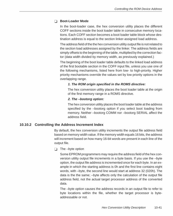
Controlling the ROM Device Address
10-41Hex Conversion Utility Description
� Boot-Loader Mode
In the boot-loader case, the hex conversion utility places the differentCOFF sections inside the boot loader table in consecutive memory loca-tions. Each COFF section becomes a boot loader table block whose des-tination address is equal to the section linker-assigned load address.
The address field of the the hex conversion utility output file is not related tothe section load addresses assigned by the linker. The address fields aresimply offsets to the beginning of the table, multiplied by the correction fac-tor (data width divided by memory width, as previously explained.)
The beginning of the boot loader table defaults to the linked load addressof the first bootable section in the COFF input file, unless you use one ofthe following mechanisms, listed here from low- to high-priority. Higherpriority mechanisms override the values set by low priority options in theoverlapping range.
1. The ROM origin specified in the ROMS directive:
The hex conversion utility places the boot loader table at the originof the first memory range in a ROMS directive.
2. The –bootorg option:
The hex conversion utility places the boot loader table at the addressspecified by the –bootorg option if you select boot loading frommemory. Neither –bootorg COMM nor –bootorg SERIAL affect theaddress field.
10.10.2 Controlling the Address Increment Index
By default, the hex conversion utility increments the output file address fieldbased on memory width value. If the memory width equals 16 bits, the addresswill increment based on how many 16-bit words are present in each line of theoutput file.
� The –byte option
Some EPROM programmers may require the address field of the hex con-version utility output file increments in a byte basis. If you use the –byteoption, the output file address is incremented once for each byte. In an ex-ample in which the starting address is 0h and the first line contains eightwords, with –byte, the second line would start at address 32 (020h). Thedata is the the same; –byte affects only the calculation of the output fileaddress field, not the actual target processor address of the converteddata.
The –byte option causes the address records in an output file to refer tobyte locations within the file, whether the target processor is byte-addressable or not.
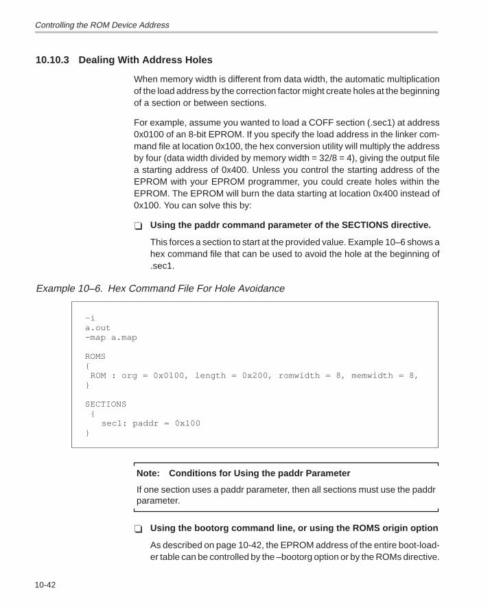
Controlling the ROM Device Address
10-42
10.10.3 Dealing With Address Holes
When memory width is different from data width, the automatic multiplicationof the load address by the correction factor might create holes at the beginningof a section or between sections.
For example, assume you wanted to load a COFF section (.sec1) at address0x0100 of an 8-bit EPROM. If you specify the load address in the linker com-mand file at location 0x100, the hex conversion utility will multiply the addressby four (data width divided by memory width = 32/8 = 4), giving the output filea starting address of 0x400. Unless you control the starting address of theEPROM with your EPROM programmer, you could create holes within theEPROM. The EPROM will burn the data starting at location 0x400 instead of0x100. You can solve this by:
� Using the paddr command parameter of the SECTIONS directive.
This forces a section to start at the provided value. Example 10–6 shows ahex command file that can be used to avoid the hole at the beginning of.sec1.
Example 10–6. Hex Command File For Hole Avoidance
–i a.out –map a.map
ROMS{ ROM : org = 0x0100, length = 0x200, romwidth = 8, memwidth = 8, }
SECTIONS {
sec1: paddr = 0x100}
Note: Conditions for Using the paddr Parameter
If one section uses a paddr parameter, then all sections must use the paddrparameter.
� Using the bootorg command line, or using the ROMS origin option
As described on page 10-42, the EPROM address of the entire boot-load-er table can be controlled by the –bootorg option or by the ROMs directive.
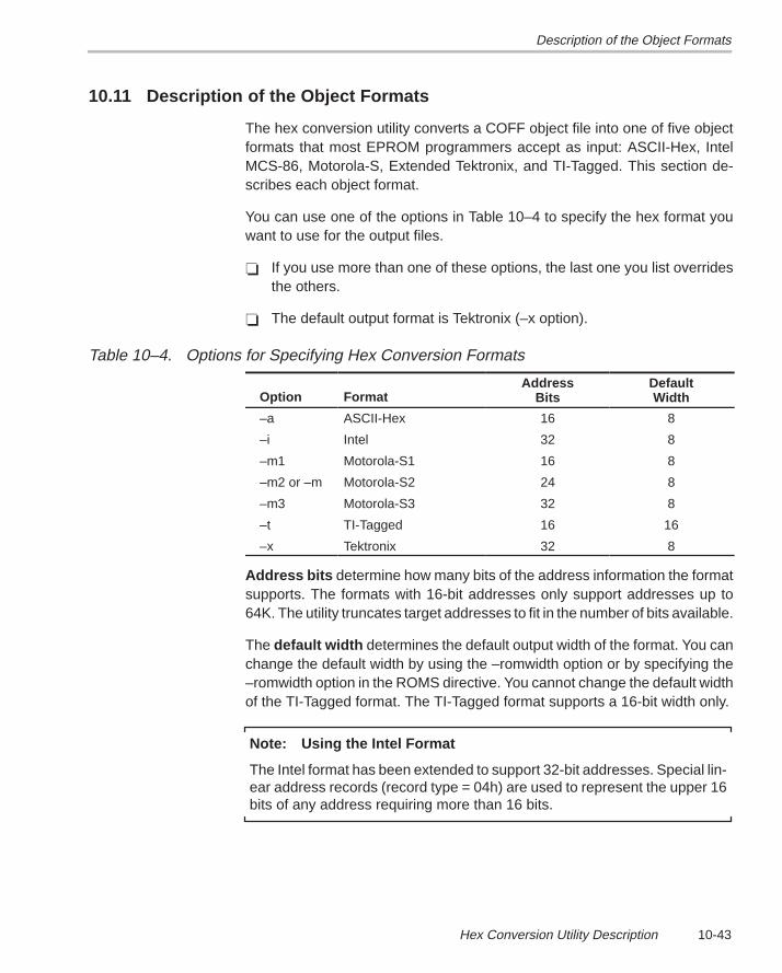
Description of the Object Formats
10-43Hex Conversion Utility Description
10.11 Description of the Object Formats
The hex conversion utility converts a COFF object file into one of five objectformats that most EPROM programmers accept as input: ASCII-Hex, IntelMCS-86, Motorola-S, Extended Tektronix, and TI-Tagged. This section de-scribes each object format.
You can use one of the options in Table 10–4 to specify the hex format youwant to use for the output files.
� If you use more than one of these options, the last one you list overridesthe others.
� The default output format is Tektronix (–x option).
Table 10–4. Options for Specifying Hex Conversion Formats
Option FormatAddress
BitsDefaultWidth
–a ASCII-Hex 16 8
–i Intel 32 8
–m1 Motorola-S1 16 8
–m2 or –m Motorola-S2 24 8
–m3 Motorola-S3 32 8
–t TI-Tagged 16 16
–x Tektronix 32 8
Address bits determine how many bits of the address information the formatsupports. The formats with 16-bit addresses only support addresses up to64K. The utility truncates target addresses to fit in the number of bits available.
The default width determines the default output width of the format. You canchange the default width by using the –romwidth option or by specifying the–romwidth option in the ROMS directive. You cannot change the default widthof the TI-Tagged format. The TI-Tagged format supports a 16-bit width only.
Note: Using the Intel Format
The Intel format has been extended to support 32-bit addresses. Special lin-ear address records (record type = 04h) are used to represent the upper 16bits of any address requiring more than 16 bits.
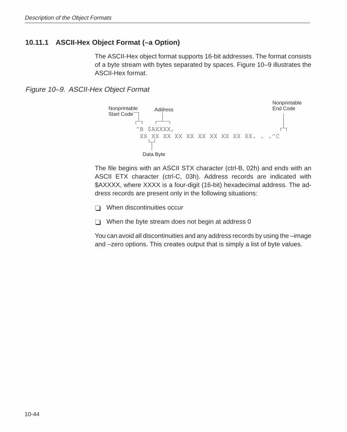
Description of the Object Formats
10-44
10.11.1 ASCII-Hex Object Format (–a Option)
The ASCII-Hex object format supports 16-bit addresses. The format consistsof a byte stream with bytes separated by spaces. Figure 10–9 illustrates theASCII-Hex format.
Figure 10–9. ASCII-Hex Object Format
^B $AXXXX, XX XX XX XX XX XX XX XX XX XX. . .^C
NonprintableStart Code
NonprintableEnd CodeAddress
Data Byte
The file begins with an ASCII STX character (ctrl-B, 02h) and ends with anASCII ETX character (ctrl-C, 03h). Address records are indicated with$AXXXX, where XXXX is a four-digit (16-bit) hexadecimal address. The ad-dress records are present only in the following situations:
� When discontinuities occur
� When the byte stream does not begin at address 0
You can avoid all discontinuities and any address records by using the –imageand –zero options. This creates output that is simply a list of byte values.
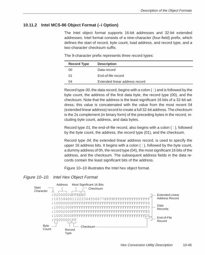
Description of the Object Formats
10-45Hex Conversion Utility Description
10.11.2 Intel MCS-86 Object Format (–i Option)
The Intel object format supports 16-bit addresses and 32-bit extendedaddresses. Intel format consists of a nine-character (four-field) prefix, whichdefines the start of record, byte count, load address, and record type, and atwo-character checksum suffix.
The 9-character prefix represents three record types:
Record Type Description
00 Data record
01 End-of-file record
04 Extended linear address record
Record type 00, the data record, begins with a colon ( : ) and is followed by thebyte count, the address of the first data byte, the record type (00), and thechecksum. Note that the address is the least significant 16 bits of a 32-bit ad-dress; this value is concatenated with the value from the most recent 04(extended linear address) record to create a full 32-bit address. The checksumis the 2s complement (in binary form) of the preceding bytes in the record, in-cluding byte count, address, and data bytes.
Record type 01, the end-of-file record, also begins with a colon ( : ), followedby the byte count, the address, the record type (01), and the checksum.
Record type 04, the extended linear address record, is used to specify theupper 16 address bits. It begins with a colon ( : ), followed by the byte count,a dummy address of 0h, the record type (04), the most significant 16 bits of theaddress, and the checksum. The subsequent address fields in the data re-cords contain the least significant bits of the address.
Figure 10–10 illustrates the Intel hex object format.
Figure 10–10. Intel Hex Object Format
:02000004FFEEE0:10334400112233445566778899FFFFFFFFFFFFFFFF:10000000FFFFFFFFFFFFFFFFFFFFFFFFFFFFFFFF00:10001000FFFFFFFFFFFFFFFFFFFFFFFFFFFFFFFFF0:10002000FFFFFFFFFFFFFFFFFFFFFFFFFFFFFFFFE0:10003000FFFFFFFFFFFFFFFFFFFFFFFFFFFFFFFFD0:00000001FF
StartCharacter
ByteCount
Checksum
DataRecords
RecordType
Address Most Significant 16 BitsChecksum
Extended LinearAddress Record
End-of-FileRecord
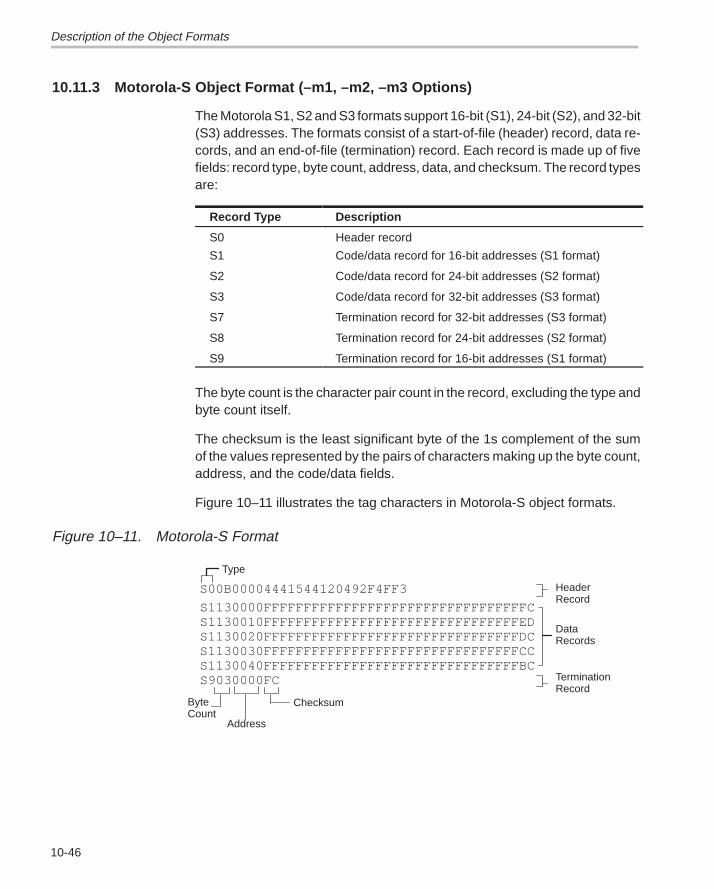
Description of the Object Formats
10-46
10.11.3 Motorola-S Object Format (–m1, –m2, –m3 Options)
The Motorola S1, S2 and S3 formats support 16-bit (S1), 24-bit (S2), and 32-bit(S3) addresses. The formats consist of a start-of-file (header) record, data re-cords, and an end-of-file (termination) record. Each record is made up of fivefields: record type, byte count, address, data, and checksum. The record typesare:
Record Type Description
S0 Header record
S1 Code/data record for 16-bit addresses (S1 format)
S2 Code/data record for 24-bit addresses (S2 format)
S3 Code/data record for 32-bit addresses (S3 format)
S7 Termination record for 32-bit addresses (S3 format)
S8 Termination record for 24-bit addresses (S2 format)
S9 Termination record for 16-bit addresses (S1 format)
The byte count is the character pair count in the record, excluding the type andbyte count itself.
The checksum is the least significant byte of the 1s complement of the sumof the values represented by the pairs of characters making up the byte count,address, and the code/data fields.
Figure 10–11 illustrates the tag characters in Motorola-S object formats.
Figure 10–11. Motorola-S Format
S1130000FFFFFFFFFFFFFFFFFFFFFFFFFFFFFFFFFCS1130010FFFFFFFFFFFFFFFFFFFFFFFFFFFFFFFFEDS1130020FFFFFFFFFFFFFFFFFFFFFFFFFFFFFFFFDCS1130030FFFFFFFFFFFFFFFFFFFFFFFFFFFFFFFFCCS1130040FFFFFFFFFFFFFFFFFFFFFFFFFFFFFFFFBCS9030000FC
ByteCount
Checksum
DataRecords
Address
HeaderRecord
TerminationRecord
S00B00004441544120492F4FF3
Type
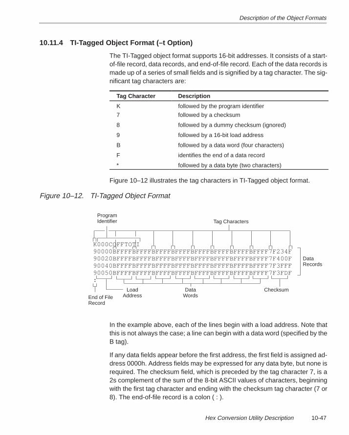
Description of the Object Formats
10-47Hex Conversion Utility Description
10.11.4 TI-Tagged Object Format (–t Option)
The TI-Tagged object format supports 16-bit addresses. It consists of a start-of-file record, data records, and end-of-file record. Each of the data records ismade up of a series of small fields and is signified by a tag character. The sig-nificant tag characters are:
Tag Character Description
K followed by the program identifier
7 followed by a checksum
8 followed by a dummy checksum (ignored)
9 followed by a 16-bit load address
B followed by a data word (four characters)
F identifies the end of a data record
* followed by a data byte (two characters)
Figure 10–12 illustrates the tag characters in TI-Tagged object format.
Figure 10–12. TI-Tagged Object Format
K000COFFTOTI90000BFFFFBFFFFBFFFFBFFFFBFFFFBFFFFBFFFFBFFFF7F234F90020BFFFFBFFFFBFFFFBFFFFBFFFFBFFFFBFFFFBFFFF7F400F90040BFFFFBFFFFBFFFFBFFFFBFFFFBFFFFBFFFFBFFFF7F3FFF90050BFFFFBFFFFBFFFFBFFFFBFFFFBFFFFBFFFFBFFFF7F3FDF:
Tag CharactersProgramIdentifier
LoadAddress
DataWords
Checksum
DataRecords
End of FileRecord
In the example above, each of the lines begin with a load address. Note thatthis is not always the case; a line can begin with a data word (specified by theB tag).
If any data fields appear before the first address, the first field is assigned ad-dress 0000h. Address fields may be expressed for any data byte, but none isrequired. The checksum field, which is preceded by the tag character 7, is a2s complement of the sum of the 8-bit ASCII values of characters, beginningwith the first tag character and ending with the checksum tag character (7 or8). The end-of-file record is a colon ( : ).
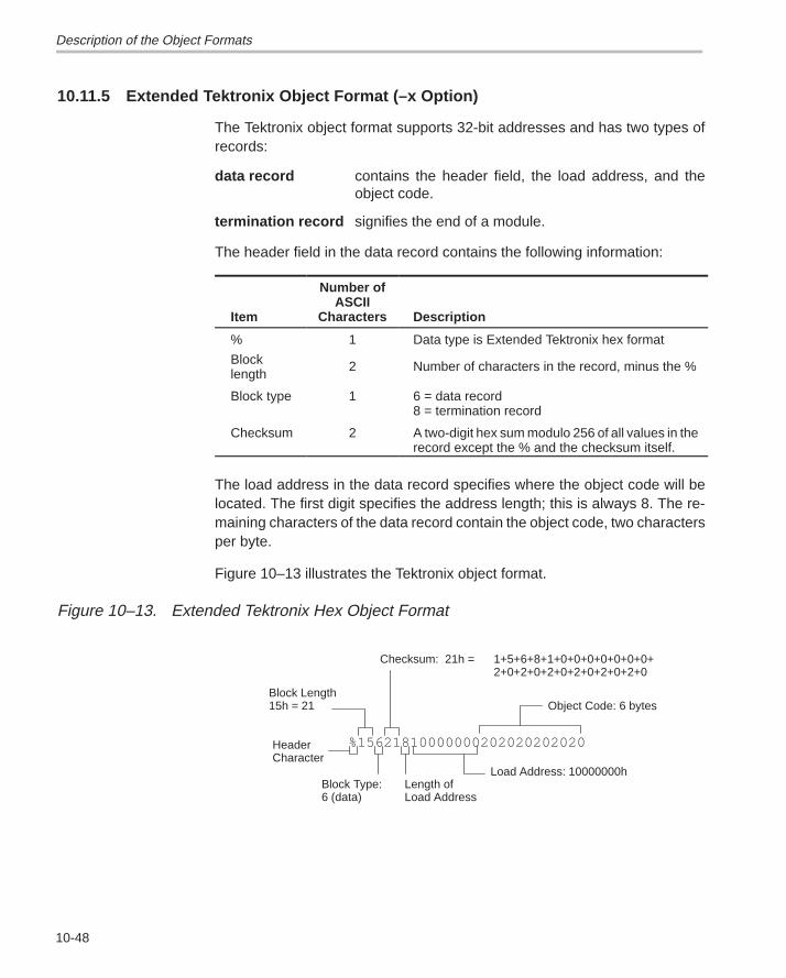
Description of the Object Formats
10-48
10.11.5 Extended Tektronix Object Format (–x Option)
The Tektronix object format supports 32-bit addresses and has two types ofrecords:
data record contains the header field, the load address, and theobject code.
termination record signifies the end of a module.
The header field in the data record contains the following information:
Item
Number ofASCII
Characters Description
% 1 Data type is Extended Tektronix hex format
Blocklength
2 Number of characters in the record, minus the %
Block type 1 6 = data record8 = termination record
Checksum 2 A two-digit hex sum modulo 256 of all values in therecord except the % and the checksum itself.
The load address in the data record specifies where the object code will belocated. The first digit specifies the address length; this is always 8. The re-maining characters of the data record contain the object code, two charactersper byte.
Figure 10–13 illustrates the Tektronix object format.
Figure 10–13. Extended Tektronix Hex Object Format
%15621810000000202020202020
Block Length 15h = 21
Checksum: 21h = 1+5+6+8+1+0+0+0+0+0+0+0+2+0+2+0+2+0+2+0+2+0+2+0
Load Address: 10000000h
HeaderCharacter
Block Type:6 (data)
Object Code: 6 bytes
Length of Load Address
Hex Conversion Utility Error Messages
10-49Hex Conversion Utility Description
10.12 Hex Conversion Utility Error Messages
section mapped to reserved memory message
Description A section or a boot-loader table is mapped into a reservedmemory area as listed in the processor memory map.
Action Correct section or boot-loader address. For valid memory loca-tions, refer to the user’s guide for the specific processor .
sections overlapping
Description Two or more COFF section load addresses overlap or a boottable address overlaps another section.
Action This problem may be caused by an incorrect translation fromload address to hex output file address that is performed by thehex conversion utility when memory width is less than datawidth. Refer to Section 10.4, page 10-7 and Section 10.10,page 10-39.
unconfigured memory
Description This error could have one of two causes:
� The COFF file contains a section whose load address fallsoutside the memory range defined in the ROMS directive.
� The boot-loader table address is not within the memoryrange defined by the ROMS directive.
Action Correct your ROM range as defined in your ROMS directive tocover the memory range as needed, or modify the section loadaddress or boot-loader table address. Remember that if theROMS directive is not used, the memory range defaults to theentire processor address space. For this reason, removing theROMS directive could also be a workaround.
Running Title—Attribute Reference
A-1 Chapter Title—Attribute Reference
Appendix A
Common Object File Format
The TMS320C3x/C4x assembler and linker create object files that are in com-mon object file format (COFF). COFF is an implementation of an object file for-mat of the same name that was developed by AT&T for use on UNIX-basedsystems. This object file format has been chosen because it encourages mod-ular programming and provides more powerful and flexible methods for man-aging code segments and target system memory.
One of the basic COFF concepts is sections. Chapter 2, Introduction to Com-mon Object File Format, discusses COFF sections in detail. If you understandsection operation, you will be able to use the TMS320 assembly languagetools more efficiently.
This appendix contains technical details about COFF object file structure.Most of this information pertains to the symbolic debugging information thatis produced by the TMS320C3x/C4x C compiler. The main purpose of this ap-pendix is to provide supplementary information for those of you who are inter-ested in the internal format of COFF object files.
Topics in this appendix include:
Topic Page
A.1 How the COFF File Is Structured A-2. . . . . . . . . . . . . . . . . . . . . . . . . . . . . . .
A.2 File Header Structure A-5. . . . . . . . . . . . . . . . . . . . . . . . . . . . . . . . . . . . . . . . . .
A.3 Optional File Header Format A-6. . . . . . . . . . . . . . . . . . . . . . . . . . . . . . . . . . .
A.4 Section Header Structure A-7. . . . . . . . . . . . . . . . . . . . . . . . . . . . . . . . . . . . . .
A.5 Structuring Relocation Information A-10. . . . . . . . . . . . . . . . . . . . . . . . . . . .
A.6 Line-Number Table Structure A-12. . . . . . . . . . . . . . . . . . . . . . . . . . . . . . . . . .
A.7 Symbol Table Structure and Content A-14. . . . . . . . . . . . . . . . . . . . . . . . . .
Appendix A
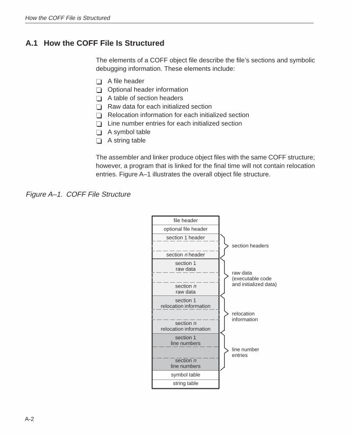
How the COFF File is Structured
A-2
A.1 How the COFF File Is Structured
The elements of a COFF object file describe the file’s sections and symbolicdebugging information. These elements include:
� A file header� Optional header information� A table of section headers� Raw data for each initialized section� Relocation information for each initialized section� Line number entries for each initialized section� A symbol table� A string table
The assembler and linker produce object files with the same COFF structure;however, a program that is linked for the final time will not contain relocationentries. Figure A–1 illustrates the overall object file structure.
Figure A–1. COFF File Structure
file header
optional file header
section 1 header
section n header
section 1raw data
section nraw data
section 1relocation information
section nrelocation information
section 1line numbers
section nline numbers
symbol table
string table
section headers
raw data(executable codeand initialized data)
relocationinformation
line numberentries
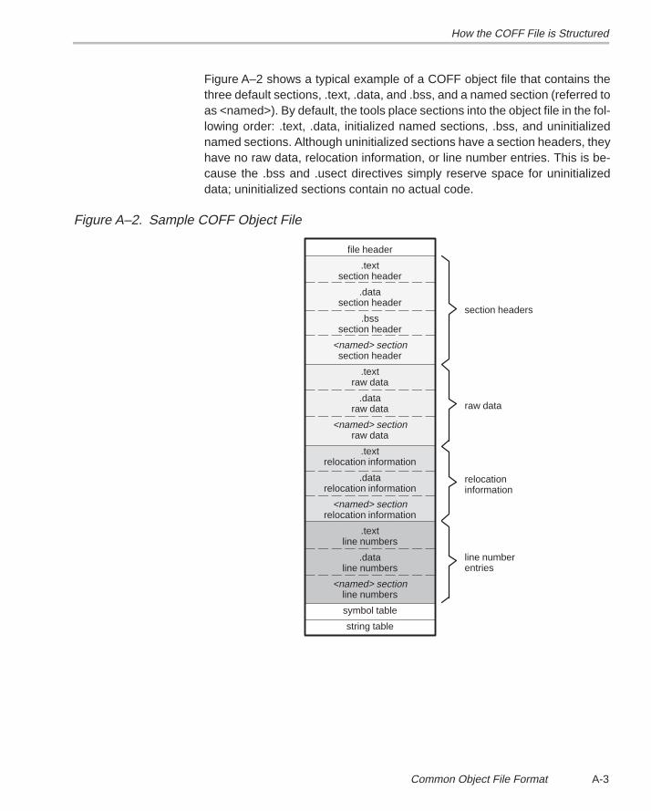
How the COFF File is Structured
A-3 Common Object File Format
Figure A–2 shows a typical example of a COFF object file that contains thethree default sections, .text, .data, and .bss, and a named section (referred toas <named>). By default, the tools place sections into the object file in the fol-lowing order: .text, .data, initialized named sections, .bss, and uninitializednamed sections. Although uninitialized sections have a section headers, theyhave no raw data, relocation information, or line number entries. This is be-cause the .bss and .usect directives simply reserve space for uninitializeddata; uninitialized sections contain no actual code.
Figure A–2. Sample COFF Object File
file header
.textsection header
.datasection header
.bsssection header
<named> sectionsection header
.textraw data
.dataraw data
<named> sectionraw data
.textrelocation information
.datarelocation information
<named> sectionrelocation information
.textline numbers
.dataline numbers
<named> sectionline numbers
symbol table
string table
section headers
raw data
relocationinformation
line numberentries
How the COFF File is Structured
A-4
A.1.1 Impact of Switching Operating Systems
The TMS320C3x/C4x COFF files are recognized by all operating system ver-sions of the development tools. When you switch from one operating systemto another, only the file header information in the COFF files needs to be byteswapped. The raw data in the COFF files does not need any changes.
The development tools can detect the difference in the file headers and auto-matically compensate for it. This is true if using only TMS320C3x/C4x devel-opment tools.
To tell the difference between COFF files, you can look at the magic numberin the optional file header. Bytes 0 and 1 contain the magic number. For theSunOS� or HP-UX� operating systems, the magic number is 108h. For theDOS operating system, the magic number is 801h.
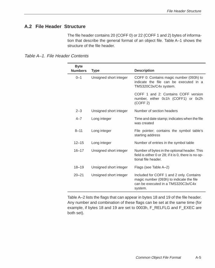
File Header Structure
A-5 Common Object File Format
A.2 File Header Structure
The file header contains 20 (COFF 0) or 22 (COFF 1 and 2) bytes of informa-tion that describe the general format of an object file. Table A–1 shows thestructure of the file header.
Table A–1. File Header Contents
ByteNumbers Type Description
0–1 Unsigned short integer COFF 0: Contains magic number (093h) toindicate the file can be executed in aTMS320C3x/C4x system.
COFF 1 and 2: Contains COFF versionnumber, either 0c1h (COFF1) or 0c2h(COFF 2)
2–3 Unsigned short integer Number of section headers
4–7 Long integer Time and date stamp; indicates when the filewas created
8–11 Long integer File pointer; contains the symbol table’sstarting address
12–15 Long integer Number of entries in the symbol table
16–17 Unsigned short integer Number of bytes in the optional header. Thisfield is either 0 or 28; if it is 0, there is no op-tional file header.
18–19 Unsigned short integer Flags (see Table A–2)
20–21 Unsigned short integer Included for COFF 1 and 2 only. Containsmagic number (093h) to indicate the filecan be executed in a TMS320C3x/C4xsystem.
Table A–2 lists the flags that can appear in bytes 18 and 19 of the file header.Any number and combination of these flags can be set at the same time (forexample, if bytes 18 and 19 are set to 0003h, F_RELFLG and F_EXEC areboth set).
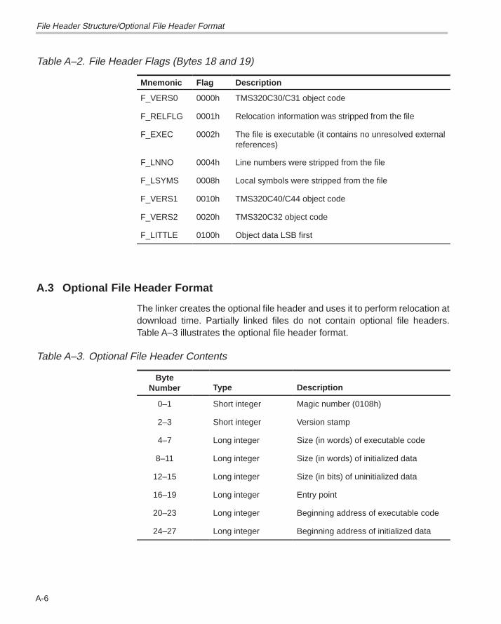
Optional File Header Format
A-6
Table A–2. File Header Flags (Bytes 18 and 19)
Mnemonic Flag Description
F_VERS0 0000h TMS320C30/C31 object code
F_RELFLG 0001h Relocation information was stripped from the file
F_EXEC 0002h The file is executable (it contains no unresolved externalreferences)
F_LNNO 0004h Line numbers were stripped from the file
F_LSYMS 0008h Local symbols were stripped from the file
F_VERS1 0010h TMS320C40/C44 object code
F_VERS2 0020h TMS320C32 object code
F_LITTLE 0100h Object data LSB first
A.3 Optional File Header Format
The linker creates the optional file header and uses it to perform relocation atdownload time. Partially linked files do not contain optional file headers.Table A–3 illustrates the optional file header format.
Table A–3. Optional File Header Contents
ByteNumber Type Description
0–1 Short integer Magic number (0108h)
2–3 Short integer Version stamp
4–7 Long integer Size (in words) of executable code
8–11 Long integer Size (in words) of initialized data
12–15 Long integer Size (in bits) of uninitialized data
16–19 Long integer Entry point
20–23 Long integer Beginning address of executable code
24–27 Long integer Beginning address of initialized data
File Header Structure/Optional File Header Format
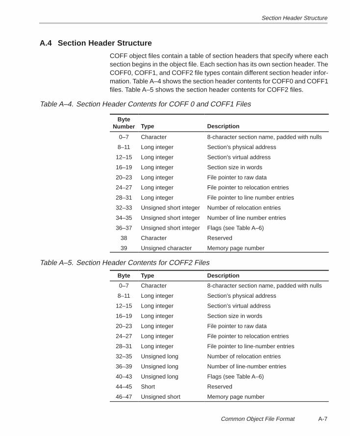
Section Header Structure
A-7 Common Object File Format
A.4 Section Header Structure
COFF object files contain a table of section headers that specify where eachsection begins in the object file. Each section has its own section header. TheCOFF0, COFF1, and COFF2 file types contain different section header infor-mation. Table A–4 shows the section header contents for COFF0 and COFF1files. Table A–5 shows the section header contents for COFF2 files.
Table A–4. Section Header Contents for COFF 0 and COFF1 Files
ByteNumber Type Description
0–7 Character 8-character section name, padded with nulls
8–11 Long integer Section’s physical address
12–15 Long integer Section’s virtual address
16–19 Long integer Section size in words
20–23 Long integer File pointer to raw data
24–27 Long integer File pointer to relocation entries
28–31 Long integer File pointer to line number entries
32–33 Unsigned short integer Number of relocation entries
34–35 Unsigned short integer Number of line number entries
36–37 Unsigned short integer Flags (see Table A–6)
38 Character Reserved
39 Unsigned character Memory page number
Table A–5. Section Header Contents for COFF2 Files
Byte Type Description
0–7 Character 8-character section name, padded with nulls
8–11 Long integer Section’s physical address
12–15 Long integer Section’s virtual address
16–19 Long integer Section size in words
20–23 Long integer File pointer to raw data
24–27 Long integer File pointer to relocation entries
28–31 Long integer File pointer to line-number entries
32–35 Unsigned long Number of relocation entries
36–39 Unsigned long Number of line-number entries
40–43 Unsigned long Flags (see Table A–6)
44–45 Short Reserved
46–47 Unsigned short Memory page number
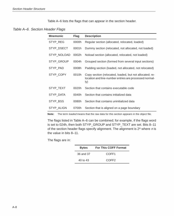
Section Header Structure
A-8
Table A–6 lists the flags that can appear in the section header.
Table A–6. Section Header Flags
Mnemonic Flag Description
STYP_REG 0000h Regular section (allocated, relocated, loaded)
STYP_DSECT 0001h Dummy section (relocated, not allocated, not loaded)
STYP_NOLOAD 0002h Noload section (allocated, relocated, not loaded)
STYP_GROUP 0004h Grouped section (formed from several input sections)
STYP_PAD 0008h Padding section (loaded, not allocated, not relocated)
STYP_COPY 0010h Copy section (relocated, loaded, but not allocated; re-location and line-number entries are processed normal-ly)
STYP_TEXT 0020h Section that contains executable code
STYP_DATA 0040h Section that contains initialized data
STYP_BSS 0080h Section that contains uninitialized data
STYP_ALIGN 0700h Section that is aligned on a page boundary
Note: The term loaded means that the raw data for this section appears in the object file.
The flags listed in Table A–6 can be combined; for example, if the flags wordis set to 024h, then both STYP_GROUP and STYP_TEXT are set. Bits 8–11of the section header flags specify alignment. The alignment is 2n where n isthe value in bits 8–11.
The flags are in:
Bytes For This COFF Format
36 and 37 COFF1
40 to 43 COFF2
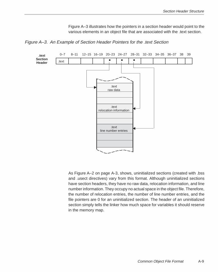
Section Header Structure
A-9 Common Object File Format
Figure A–3 illustrates how the pointers in a section header would point to thevarious elements in an object file that are associated with the .text section.
Figure A–3. An Example of Section Header Pointers for the .text Section
.text
.textSectionHeader
.textraw data
.textrelocation information
.textline number entries
• • •0–7 8–11 12–15 16–19 20–23 24–27 28–31 32–33 34–35 36–37 38 39
As Figure A–2 on page A-3, shows, uninitialized sections (created with .bssand .usect directives) vary from this format. Although uninitialized sectionshave section headers, they have no raw data, relocation information, and linenumber information. They occupy no actual space in the object file. Therefore,the number of relocation entries, the number of line number entries, and thefile pointers are 0 for an uninitialized section. The header of an uninitializedsection simply tells the linker how much space for variables it should reservein the memory map.
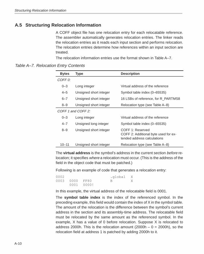
Structuring Relocation Information
A-10
A.5 Structuring Relocation Information
A COFF object file has one relocation entry for each relocatable reference.The assembler automatically generates relocation entries. The linker readsthe relocation entries as it reads each input section and performs relocation.The relocation entries determine how references within an input section aretreated.
The relocation information entries use the format shown in Table A–7.
Table A–7. Relocation Entry Contents
Bytes Type Description
COFF 0:
0–3 Long integer Virtual address of the reference
4–5 Unsigned short integer Symbol table index (0–65535)
6–7 Unsigned short integer 16 LSBs of reference, for R_PARTMS8
8–9 Unsigned short integer Relocation type (see Table A–8)
COFF 1 and COFF 2:
0–3 Long integer Virtual address of the reference
4–7 Unsigned long integer Symbol table index (0–65535)
8–9 Unsigned short integer COFF 1: ReservedCOFF 2: Additional byte used for ex-tended address calculations
10–11 Unsigned short integer Relocation type (see Table A–8)
The virtual address is the symbol’s address in the current section before re-location; it specifies where a relocation must occur. (This is the address of thefield in the object code that must be patched.)
Following is an example of code that generates a relocation entry:
0002 .global X0003 0000 FF80 B X
0001 0000!
In this example, the virtual address of the relocatable field is 0001.
The symbol table index is the index of the referenced symbol. In thepreceding example, this field would contain the index of X in the symbol table.The amount of the relocation is the difference between the symbol’s currentaddress in the section and its assembly-time address. The relocatable fieldmust be relocated by the same amount as the referenced symbol. In theexample, X has a value of 0 before relocation. Suppose X is relocated toaddress 2000h. This is the relocation amount (2000h – 0 = 2000h), so therelocation field at address 1 is patched by adding 2000h to it.
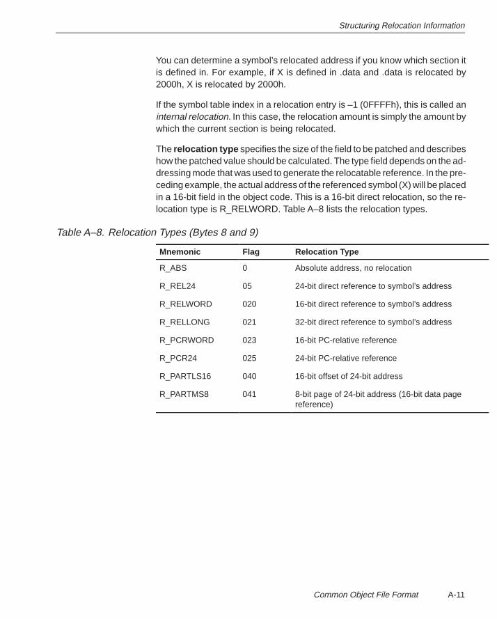
Structuring Relocation Information
A-11 Common Object File Format
You can determine a symbol’s relocated address if you know which section itis defined in. For example, if X is defined in .data and .data is relocated by2000h, X is relocated by 2000h.
If the symbol table index in a relocation entry is –1 (0FFFFh), this is called aninternal relocation. In this case, the relocation amount is simply the amount bywhich the current section is being relocated.
The relocation type specifies the size of the field to be patched and describeshow the patched value should be calculated. The type field depends on the ad-dressing mode that was used to generate the relocatable reference. In the pre-ceding example, the actual address of the referenced symbol (X) will be placedin a 16-bit field in the object code. This is a 16-bit direct relocation, so the re-location type is R_RELWORD. Table A–8 lists the relocation types.
Table A–8. Relocation Types (Bytes 8 and 9)
Mnemonic Flag Relocation Type
R_ABS 0 Absolute address, no relocation
R_REL24 05 24-bit direct reference to symbol’s address
R_RELWORD 020 16-bit direct reference to symbol’s address
R_RELLONG 021 32-bit direct reference to symbol’s address
R_PCRWORD 023 16-bit PC-relative reference
R_PCR24 025 24-bit PC-relative reference
R_PARTLS16 040 16-bit offset of 24-bit address
R_PARTMS8 041 8-bit page of 24-bit address (16-bit data page reference)
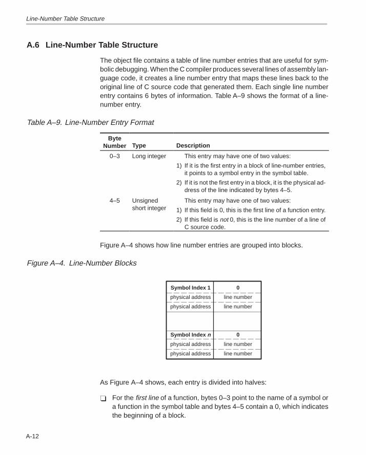
Line-Number Table Structure
A-12
A.6 Line-Number Table Structure
The object file contains a table of line number entries that are useful for sym-bolic debugging. When the C compiler produces several lines of assembly lan-guage code, it creates a line number entry that maps these lines back to theoriginal line of C source code that generated them. Each single line numberentry contains 6 bytes of information. Table A–9 shows the format of a line-number entry.
Table A–9. Line-Number Entry Format
ByteNumber Type Description
0–3 Long integer This entry may have one of two values:
1) If it is the first entry in a block of line-number entries,it points to a symbol entry in the symbol table.
2) If it is not the first entry in a block, it is the physical ad-dress of the line indicated by bytes 4–5.
4–5 Unsignedshort integer
This entry may have one of two values:
1) If this field is 0, this is the first line of a function entry.
2) If this field is not 0, this is the line number of a line ofC source code.
Figure A–4 shows how line number entries are grouped into blocks.
Figure A–4. Line-Number Blocks
Symbol Index 1
physical address
physical address
Symbol Index n
physical address
physical address
0
line number
line number
0
line number
line number
As Figure A–4 shows, each entry is divided into halves:
� For the first line of a function, bytes 0–3 point to the name of a symbol ora function in the symbol table and bytes 4–5 contain a 0, which indicatesthe beginning of a block.
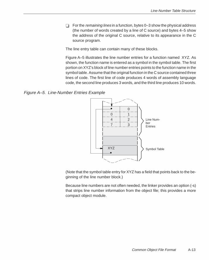
Line-Number Table Structure
A-13 Common Object File Format
� For the remaining lines in a function, bytes 0–3 show the physical address(the number of words created by a line of C source) and bytes 4–5 showthe address of the original C source, relative to its appearance in the Csource program.
The line entry table can contain many of these blocks.
Figure A–5 illustrates the line number entries for a function named XYZ. Asshown, the function name is entered as a symbol in the symbol table. The firstportion on XYZ’s block of line number entries points to the function name in thesymbol table. Assume that the original function in the C source contained threelines of code. The first line of code produces 4 words of assembly languagecode, the second line produces 3 words, and the third line produces 10 words.
Figure A–5. Line-Number Entries Example
0
1
2
3
0
4
7
XYZ
•
•
Line Num-berEntries
Symbol Table
(Note that the symbol table entry for XYZ has a field that points back to the be-ginning of the line number block.)
Because line numbers are not often needed, the linker provides an option (-s)that strips line number information from the object file; this provides a morecompact object module.
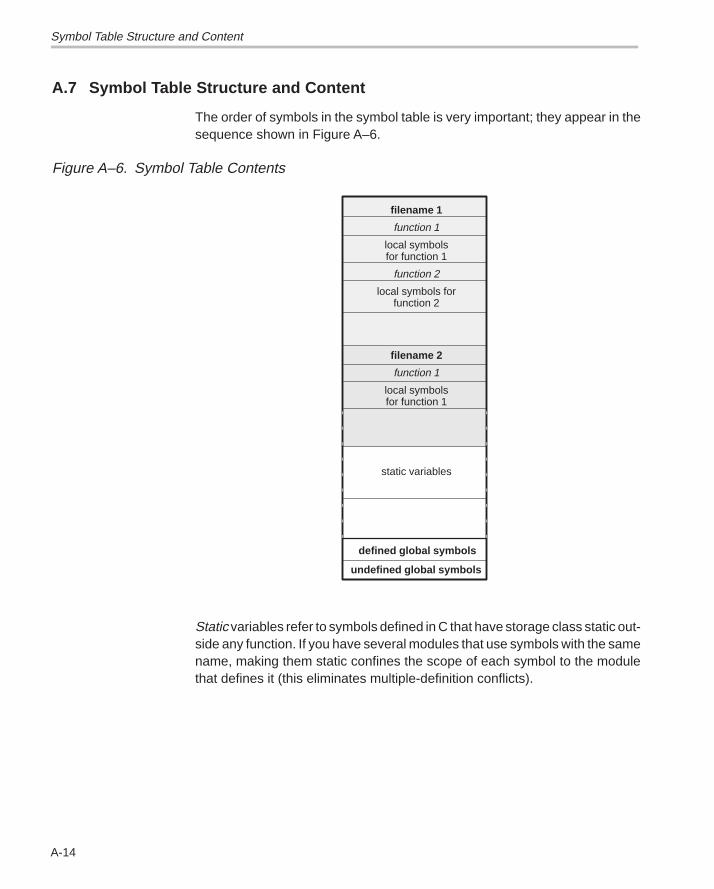
Symbol Table Structure and Content
A-14
A.7 Symbol Table Structure and Content
The order of symbols in the symbol table is very important; they appear in thesequence shown in Figure A–6.
Figure A–6. Symbol Table Contents
filename 1
function 1
local symbolsfor function 1
function 2
local symbols forfunction 2
filename 2
function 1
local symbolsfor function 1
static variables
defined global symbols
undefined global symbols
Static variables refer to symbols defined in C that have storage class static out-side any function. If you have several modules that use symbols with the samename, making them static confines the scope of each symbol to the modulethat defines it (this eliminates multiple-definition conflicts).
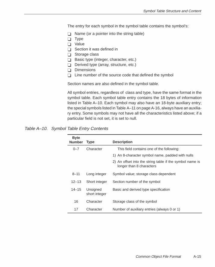
Symbol Table Structure and Content
A-15 Common Object File Format
The entry for each symbol in the symbol table contains the symbol’s:
� Name (or a pointer into the string table)� Type� Value� Section it was defined in� Storage class� Basic type (integer, character, etc.)� Derived type (array, structure, etc.)� Dimensions� Line number of the source code that defined the symbol
Section names are also defined in the symbol table.
All symbol entries, regardless of class and type, have the same format in thesymbol table. Each symbol table entry contains the 18 bytes of informationlisted in Table A–10. Each symbol may also have an 18-byte auxiliary entry;the special symbols listed in Table A–11 on page A-16, always have an auxilia-ry entry. Some symbols may not have all the characteristics listed above; if aparticular field is not set, it is set to null.
Table A–10. Symbol Table Entry Contents
ByteNumber Type Description
0–7 Character This field contains one of the following:
1) An 8-character symbol name, padded with nulls
2) An offset into the string table if the symbol name islonger than 8 characters
8–11 Long integer Symbol value; storage class dependent
12–13 Short integer Section number of the symbol
14–15 Unsignedshort integer
Basic and derived type specification
16 Character Storage class of the symbol
17 Character Number of auxiliary entries (always 0 or 1)
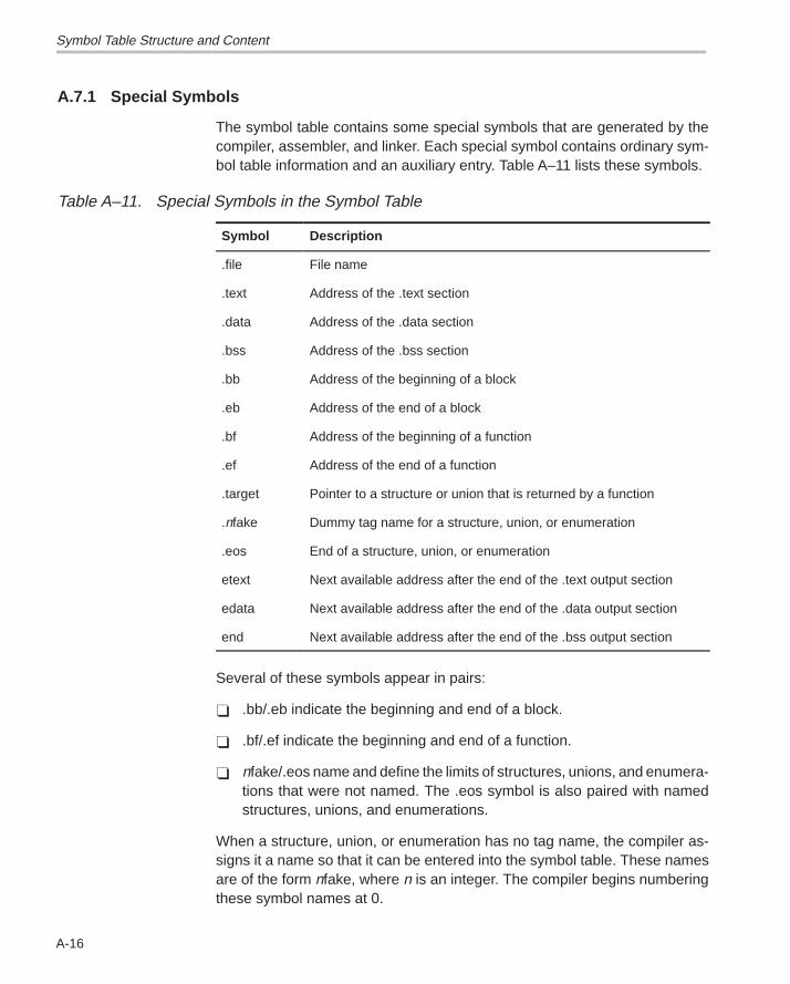
Symbol Table Structure and Content
A-16
A.7.1 Special Symbols
The symbol table contains some special symbols that are generated by thecompiler, assembler, and linker. Each special symbol contains ordinary sym-bol table information and an auxiliary entry. Table A–11 lists these symbols.
Table A–11. Special Symbols in the Symbol Table
Symbol Description
.file File name
.text Address of the .text section
.data Address of the .data section
.bss Address of the .bss section
.bb Address of the beginning of a block
.eb Address of the end of a block
.bf Address of the beginning of a function
.ef Address of the end of a function
.target Pointer to a structure or union that is returned by a function
.nfake Dummy tag name for a structure, union, or enumeration
.eos End of a structure, union, or enumeration
etext Next available address after the end of the .text output section
edata Next available address after the end of the .data output section
end Next available address after the end of the .bss output section
Several of these symbols appear in pairs:
� .bb/.eb indicate the beginning and end of a block.
� .bf/.ef indicate the beginning and end of a function.
� nfake/.eos name and define the limits of structures, unions, and enumera-tions that were not named. The .eos symbol is also paired with namedstructures, unions, and enumerations.
When a structure, union, or enumeration has no tag name, the compiler as-signs it a name so that it can be entered into the symbol table. These namesare of the form nfake, where n is an integer. The compiler begins numberingthese symbol names at 0.
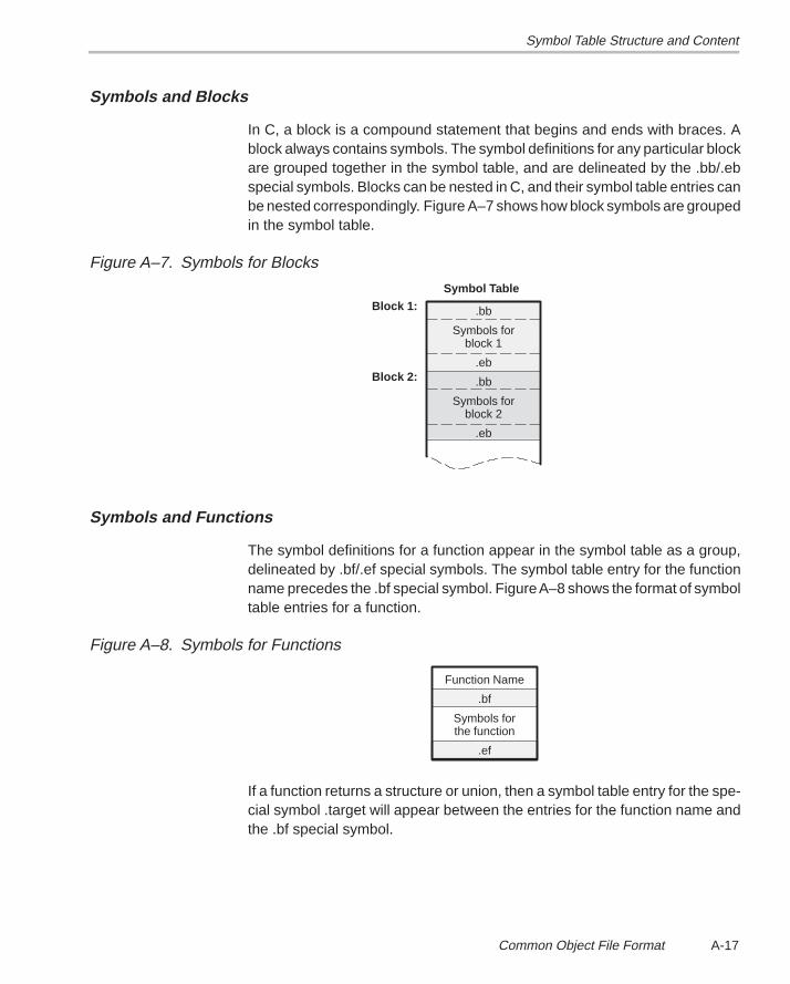
Symbol Table Structure and Content
A-17 Common Object File Format
Symbols and Blocks
In C, a block is a compound statement that begins and ends with braces. Ablock always contains symbols. The symbol definitions for any particular blockare grouped together in the symbol table, and are delineated by the .bb/.ebspecial symbols. Blocks can be nested in C, and their symbol table entries canbe nested correspondingly. Figure A–7 shows how block symbols are groupedin the symbol table.
Figure A–7. Symbols for Blocks
.bb
Symbols forblock 1
.eb
.bb
Symbols forblock 2
.eb
Symbol Table
Block 1:
Block 2:
Symbols and Functions
The symbol definitions for a function appear in the symbol table as a group,delineated by .bf/.ef special symbols. The symbol table entry for the functionname precedes the .bf special symbol. Figure A–8 shows the format of symboltable entries for a function.
Figure A–8. Symbols for Functions
Function Name
.bf
Symbols forthe function
.ef
If a function returns a structure or union, then a symbol table entry for the spe-cial symbol .target will appear between the entries for the function name andthe .bf special symbol.
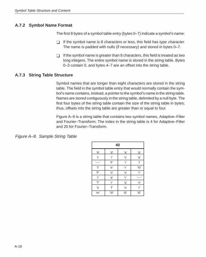
Symbol Table Structure and Content
A-18
A.7.2 Symbol Name Format
The first 8 bytes of a symbol table entry (bytes 0–7) indicate a symbol’s name:
� If the symbol name is 8 characters or less, this field has type character.The name is padded with nulls (if necessary) and stored in bytes 0–7.
� If the symbol name is greater than 8 characters, this field is treated as twolong integers. The entire symbol name is stored in the string table. Bytes0–3 contain 0, and bytes 4–7 are an offset into the string table.
A.7.3 String Table Structure
Symbol names that are longer than eight characters are stored in the stringtable. The field in the symbol table entry that would normally contain the sym-bol’s name contains, instead, a pointer to the symbol’s name in the string table.Names are stored contiguously in the string table, delimited by a null byte. Thefirst four bytes of the string table contain the size of the string table in bytes;thus, offsets into the string table are greater than or equal to four.
Figure A–9 is a string table that contains two symbol names, Adaptive–Filterand Fourier–Transform. The index in the string table is 4 for Adaptive–Filterand 20 for Fourier–Transform.
Figure A–9. Sample String Table
‘A’ ‘d’ ‘a’ ‘p’
‘t’ ‘i’ ‘v’ ‘e’
‘—’ ‘F’ ‘i’ ‘l’
‘t’ ‘e’ ‘r’ ‘\0’
‘F’ ‘o’ ‘u’ ‘r’
‘i’ ‘e’ ‘r’ ‘—’
‘T’ ‘r’ ‘a’ ‘n’
‘s’ ‘f’ ‘o’ ‘r’
‘m’ ‘\0’ \0’ \0’
40
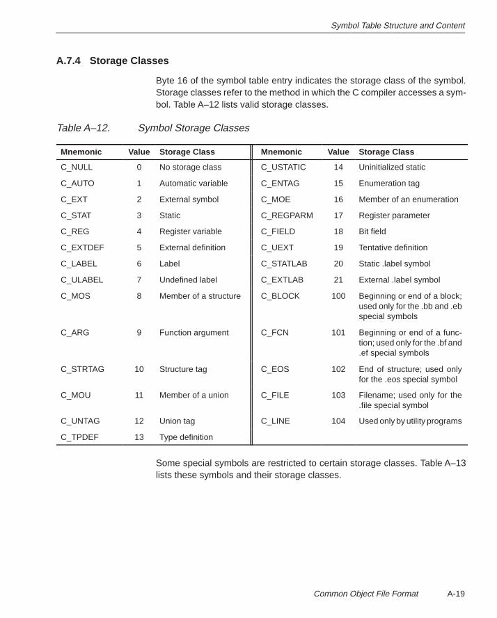
Symbol Table Structure and Content
A-19 Common Object File Format
A.7.4 Storage Classes
Byte 16 of the symbol table entry indicates the storage class of the symbol.Storage classes refer to the method in which the C compiler accesses a sym-bol. Table A–12 lists valid storage classes.
Table A–12. Symbol Storage Classes
Mnemonic Value Storage Class Mnemonic Value Storage Class
C_NULL 0 No storage class C_USTATIC 14 Uninitialized static
C_AUTO 1 Automatic variable C_ENTAG 15 Enumeration tag
C_EXT 2 External symbol C_MOE 16 Member of an enumeration
C_STAT 3 Static C_REGPARM 17 Register parameter
C_REG 4 Register variable C_FIELD 18 Bit field
C_EXTDEF 5 External definition C_UEXT 19 Tentative definition
C_LABEL 6 Label C_STATLAB 20 Static .label symbol
C_ULABEL 7 Undefined label C_EXTLAB 21 External .label symbol
C_MOS 8 Member of a structure C_BLOCK 100 Beginning or end of a block;used only for the .bb and .ebspecial symbols
C_ARG 9 Function argument C_FCN 101 Beginning or end of a func-tion; used only for the .bf and.ef special symbols
C_STRTAG 10 Structure tag C_EOS 102 End of structure; used onlyfor the .eos special symbol
C_MOU 11 Member of a union C_FILE 103 Filename; used only for the.file special symbol
C_UNTAG 12 Union tag C_LINE 104 Used only by utility programs
C_TPDEF 13 Type definition
Some special symbols are restricted to certain storage classes. Table A–13lists these symbols and their storage classes.
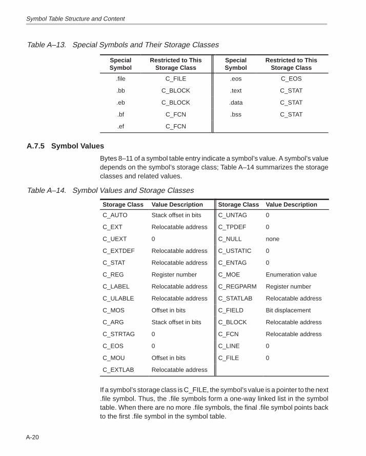
Symbol Table Structure and Content
A-20
Table A–13. Special Symbols and Their Storage Classes
SpecialSymbol
Restricted to ThisStorage Class
SpecialSymbol
Restricted to ThisStorage Class
.file C_FILE .eos C_EOS
.bb C_BLOCK .text C_STAT
.eb C_BLOCK .data C_STAT
.bf C_FCN .bss C_STAT
.ef C_FCN
A.7.5 Symbol Values
Bytes 8–11 of a symbol table entry indicate a symbol’s value. A symbol’s valuedepends on the symbol’s storage class; Table A–14 summarizes the storageclasses and related values.
Table A–14. Symbol Values and Storage Classes
Storage Class Value Description Storage Class Value Description
C_AUTO Stack offset in bits C_UNTAG 0
C_EXT Relocatable address C_TPDEF 0
C_UEXT 0 C_NULL none
C_EXTDEF Relocatable address C_USTATIC 0
C_STAT Relocatable address C_ENTAG 0
C_REG Register number C_MOE Enumeration value
C_LABEL Relocatable address C_REGPARM Register number
C_ULABLE Relocatable address C_STATLAB Relocatable address
C_MOS Offset in bits C_FIELD Bit displacement
C_ARG Stack offset in bits C_BLOCK Relocatable address
C_STRTAG 0 C_FCN Relocatable address
C_EOS 0 C_LINE 0
C_MOU Offset in bits C_FILE 0
C_EXTLAB Relocatable address
If a symbol’s storage class is C_FILE, the symbol’s value is a pointer to the next.file symbol. Thus, the .file symbols form a one-way linked list in the symboltable. When there are no more .file symbols, the final .file symbol points backto the first .file symbol in the symbol table.
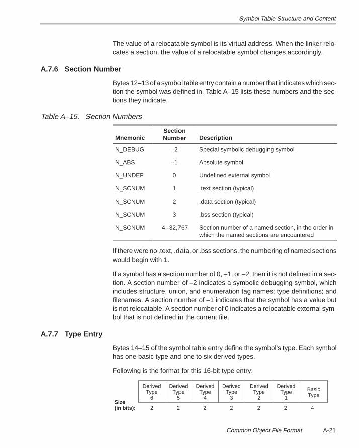
Symbol Table Structure and Content
A-21 Common Object File Format
The value of a relocatable symbol is its virtual address. When the linker relo-cates a section, the value of a relocatable symbol changes accordingly.
A.7.6 Section Number
Bytes 12–13 of a symbol table entry contain a number that indicates which sec-tion the symbol was defined in. Table A–15 lists these numbers and the sec-tions they indicate.
Table A–15. Section Numbers
MnemonicSectionNumber Description
N_DEBUG –2 Special symbolic debugging symbol
N_ABS –1 Absolute symbol
N_UNDEF 0 Undefined external symbol
N_SCNUM 1 .text section (typical)
N_SCNUM 2 .data section (typical)
N_SCNUM 3 .bss section (typical)
N_SCNUM 4–32,767 Section number of a named section, in the order inwhich the named sections are encountered
If there were no .text, .data, or .bss sections, the numbering of named sectionswould begin with 1.
If a symbol has a section number of 0, –1, or –2, then it is not defined in a sec-tion. A section number of –2 indicates a symbolic debugging symbol, whichincludes structure, union, and enumeration tag names; type definitions; andfilenames. A section number of –1 indicates that the symbol has a value butis not relocatable. A section number of 0 indicates a relocatable external sym-bol that is not defined in the current file.
A.7.7 Type Entry
Bytes 14–15 of the symbol table entry define the symbol’s type. Each symbolhas one basic type and one to six derived types.
Following is the format for this 16-bit type entry:
DerivedType
6
DerivedType
5
DerivedType
4
DerivedType
3
DerivedType
2
DerivedType
1
BasicType
2 2 2 2 2 2 4Size (in bits):
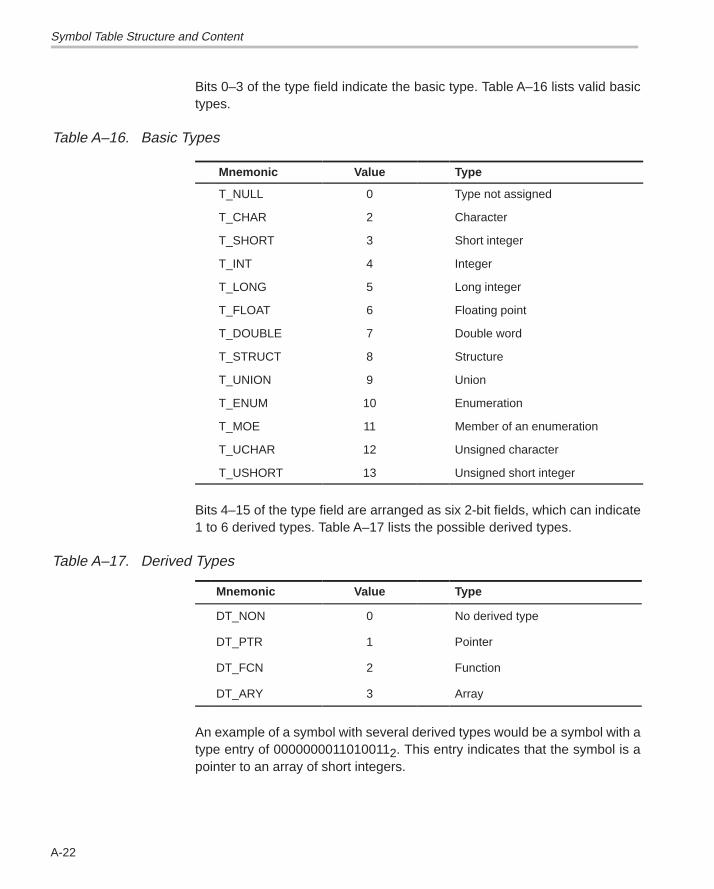
Symbol Table Structure and Content
A-22
Bits 0–3 of the type field indicate the basic type. Table A–16 lists valid basictypes.
Table A–16. Basic Types
Mnemonic Value Type
T_NULL 0 Type not assigned
T_CHAR 2 Character
T_SHORT 3 Short integer
T_INT 4 Integer
T_LONG 5 Long integer
T_FLOAT 6 Floating point
T_DOUBLE 7 Double word
T_STRUCT 8 Structure
T_UNION 9 Union
T_ENUM 10 Enumeration
T_MOE 11 Member of an enumeration
T_UCHAR 12 Unsigned character
T_USHORT 13 Unsigned short integer
Bits 4–15 of the type field are arranged as six 2-bit fields, which can indicate1 to 6 derived types. Table A–17 lists the possible derived types.
Table A–17. Derived Types
Mnemonic Value Type
DT_NON 0 No derived type
DT_PTR 1 Pointer
DT_FCN 2 Function
DT_ARY 3 Array
An example of a symbol with several derived types would be a symbol with atype entry of 00000000110100112. This entry indicates that the symbol is apointer to an array of short integers.
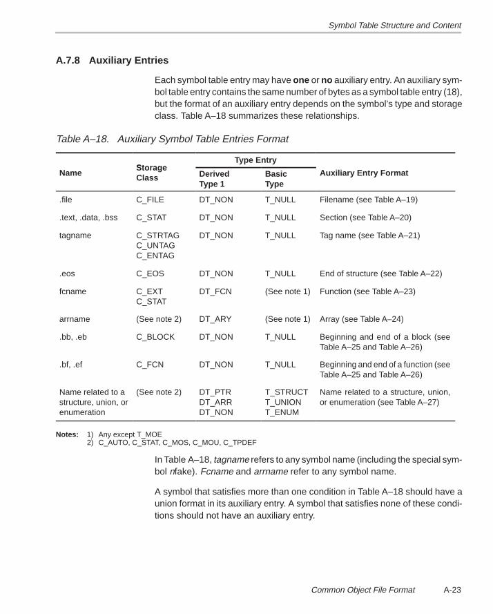
Symbol Table Structure and Content
A-23 Common Object File Format
A.7.8 Auxiliary Entries
Each symbol table entry may have one or no auxiliary entry. An auxiliary sym-bol table entry contains the same number of bytes as a symbol table entry (18),but the format of an auxiliary entry depends on the symbol’s type and storageclass. Table A–18 summarizes these relationships.
Table A–18. Auxiliary Symbol Table Entries Format
StorageType Entry
NameStorageClass Derived
Type 1BasicType
Auxiliary Entry Format
.file C_FILE DT_NON T_NULL Filename (see Table A–19)
.text, .data, .bss C_STAT DT_NON T_NULL Section (see Table A–20)
tagname C_STRTAGC_UNTAGC_ENTAG
DT_NON T_NULL Tag name (see Table A–21)
.eos C_EOS DT_NON T_NULL End of structure (see Table A–22)
fcname C_EXTC_STAT
DT_FCN (See note 1) Function (see Table A–23)
arrname (See note 2) DT_ARY (See note 1) Array (see Table A–24)
.bb, .eb C_BLOCK DT_NON T_NULL Beginning and end of a block (seeTable A–25 and Table A–26)
.bf, .ef C_FCN DT_NON T_NULL Beginning and end of a function (seeTable A–25 and Table A–26)
Name related to astructure, union, orenumeration
(See note 2) DT_PTRDT_ARRDT_NON
T_STRUCTT_UNIONT_ENUM
Name related to a structure, union,or enumeration (see Table A–27)
Notes: 1) Any except T_MOE 2) C_AUTO, C_STAT, C_MOS, C_MOU, C_TPDEF
In Table A–18, tagname refers to any symbol name (including the special sym-bol nfake). Fcname and arrname refer to any symbol name.
A symbol that satisfies more than one condition in Table A–18 should have aunion format in its auxiliary entry. A symbol that satisfies none of these condi-tions should not have an auxiliary entry.
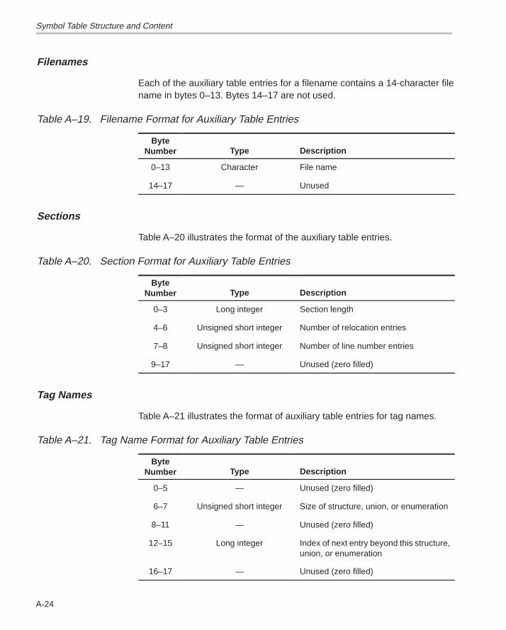
Symbol Table Structure and Content
A-24
Filenames
Each of the auxiliary table entries for a filename contains a 14-character filename in bytes 0–13. Bytes 14–17 are not used.
Table A–19. Filename Format for Auxiliary Table Entries
ByteNumber Type Description
0–13 Character File name
14–17 — Unused
Sections
Table A–20 illustrates the format of the auxiliary table entries.
Table A–20. Section Format for Auxiliary Table Entries
ByteNumber Type Description
0–3 Long integer Section length
4–6 Unsigned short integer Number of relocation entries
7–8 Unsigned short integer Number of line number entries
9–17 — Unused (zero filled)
Tag Names
Table A–21 illustrates the format of auxiliary table entries for tag names.
Table A–21. Tag Name Format for Auxiliary Table Entries
ByteNumber Type Description
0–5 — Unused (zero filled)
6–7 Unsigned short integer Size of structure, union, or enumeration
8–11 — Unused (zero filled)
12–15 Long integer Index of next entry beyond this structure,union, or enumeration
16–17 — Unused (zero filled)
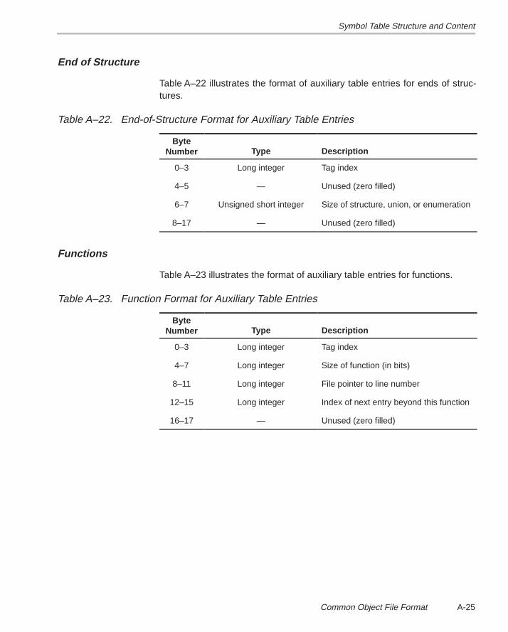
Symbol Table Structure and Content
A-25 Common Object File Format
End of Structure
Table A–22 illustrates the format of auxiliary table entries for ends of struc-tures.
Table A–22. End-of-Structure Format for Auxiliary Table Entries
ByteNumber Type Description
0–3 Long integer Tag index
4–5 — Unused (zero filled)
6–7 Unsigned short integer Size of structure, union, or enumeration
8–17 — Unused (zero filled)
Functions
Table A–23 illustrates the format of auxiliary table entries for functions.
Table A–23. Function Format for Auxiliary Table Entries
ByteNumber Type Description
0–3 Long integer Tag index
4–7 Long integer Size of function (in bits)
8–11 Long integer File pointer to line number
12–15 Long integer Index of next entry beyond this function
16–17 — Unused (zero filled)
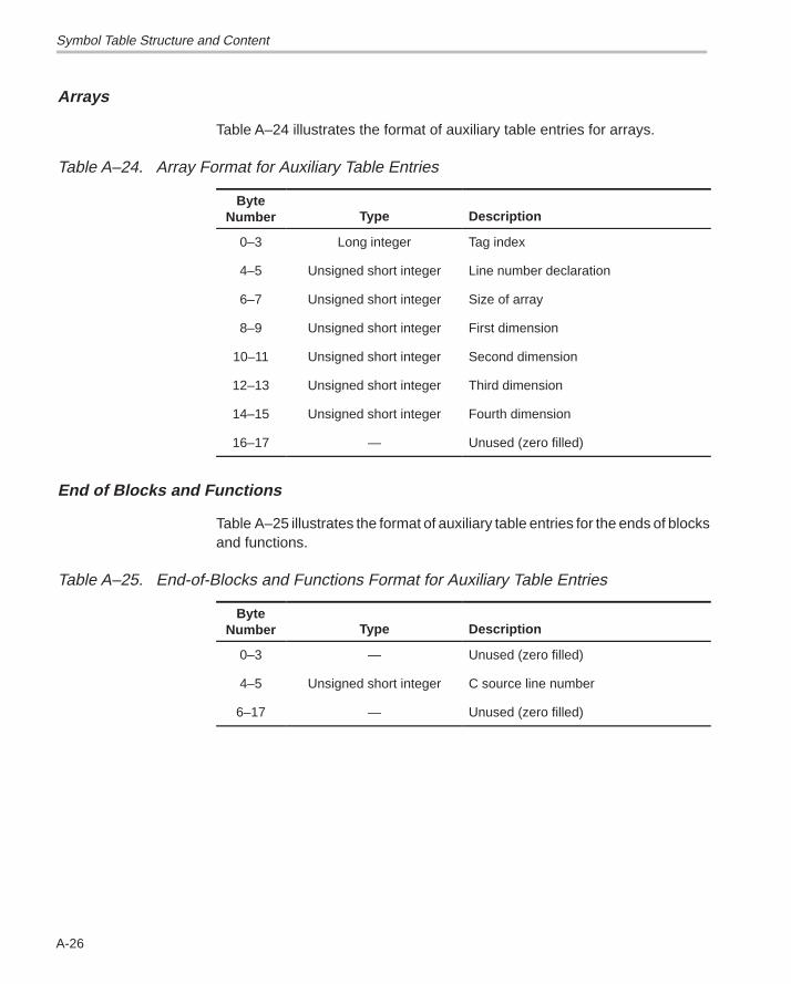
Symbol Table Structure and Content
A-26
Arrays
Table A–24 illustrates the format of auxiliary table entries for arrays.
Table A–24. Array Format for Auxiliary Table Entries
ByteNumber Type Description
0–3 Long integer Tag index
4–5 Unsigned short integer Line number declaration
6–7 Unsigned short integer Size of array
8–9 Unsigned short integer First dimension
10–11 Unsigned short integer Second dimension
12–13 Unsigned short integer Third dimension
14–15 Unsigned short integer Fourth dimension
16–17 — Unused (zero filled)
End of Blocks and Functions
Table A–25 illustrates the format of auxiliary table entries for the ends of blocksand functions.
Table A–25. End-of-Blocks and Functions Format for Auxiliary Table Entries
ByteNumber Type Description
0–3 — Unused (zero filled)
4–5 Unsigned short integer C source line number
6–17 — Unused (zero filled)
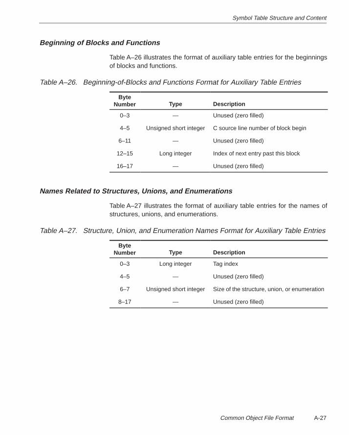
Symbol Table Structure and Content
A-27 Common Object File Format
Beginning of Blocks and Functions
Table A–26 illustrates the format of auxiliary table entries for the beginningsof blocks and functions.
Table A–26. Beginning-of-Blocks and Functions Format for Auxiliary Table Entries
ByteNumber Type Description
0–3 — Unused (zero filled)
4–5 Unsigned short integer C source line number of block begin
6–11 — Unused (zero filled)
12–15 Long integer Index of next entry past this block
16–17 — Unused (zero filled)
Names Related to Structures, Unions, and Enumerations
Table A–27 illustrates the format of auxiliary table entries for the names ofstructures, unions, and enumerations.
Table A–27. Structure, Union, and Enumeration Names Format for Auxiliary Table Entries
ByteNumber Type Description
0–3 Long integer Tag index
4–5 — Unused (zero filled)
6–7 Unsigned short integer Size of the structure, union, or enumeration
8–17 — Unused (zero filled)
Running Title—Attribute Reference
B-1 Chapter Title—Attribute Reference
Appendix A
Symbolic Debugging Directives
The TMS320C3x/C4x assembler supports several directives that theTMS320C3x/C4x C compiler uses for symbolic debugging:
� The .sym directive defines a global variable, a local variable, or a function.Several parameters allow you to associate various debugging informationwith the symbol or function.
� The .stag , .etag , and .utag directives define structures, enumerations,and unions, respectively. The .member directive specifies a member of astructure, enumeration, or union. The .eos directive ends a structure, enu-meration, or union definition.
� The .func and .endfunc directives specify the bounds of C blocks.
� The .block and .endblock directives specify the bounds of C blocks.
� The .file directive defines a symbol in the symbol table that identifies thecurrent source file name.
� The .line directive identifies the line number of a C source statement.
These symbolic debugging directives are not usually listed in the assemblylanguage file that the compiler creates. If you want them to be listed, invokethe compiler with the -g option, as shown below:
cl30 –g <input file>
This appendix contains an alphabetical directory of the symbolic debuggingdirectives. Each directive contains an example of C source and the resultingassembly language code.
Appendix B
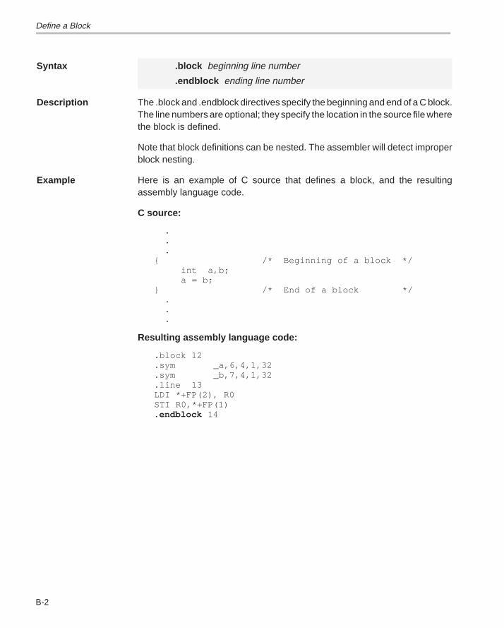
Define a Block
B-2
Syntax .block beginning line number
.endblock ending line number
Description The .block and .endblock directives specify the beginning and end of a C block.The line numbers are optional; they specify the location in the source file wherethe block is defined.
Note that block definitions can be nested. The assembler will detect improperblock nesting.
Example Here is an example of C source that defines a block, and the resultingassembly language code.
C source:
. . . { /* Beginning of a block */ int a,b; a = b; } /* End of a block */ . . .
Resulting assembly language code:
.block 12 .sym _a,6,4,1,32 .sym _b,7,4,1,32 .line 13 LDI *+FP(2), R0 STI R0,*+FP(1) .endblock 14
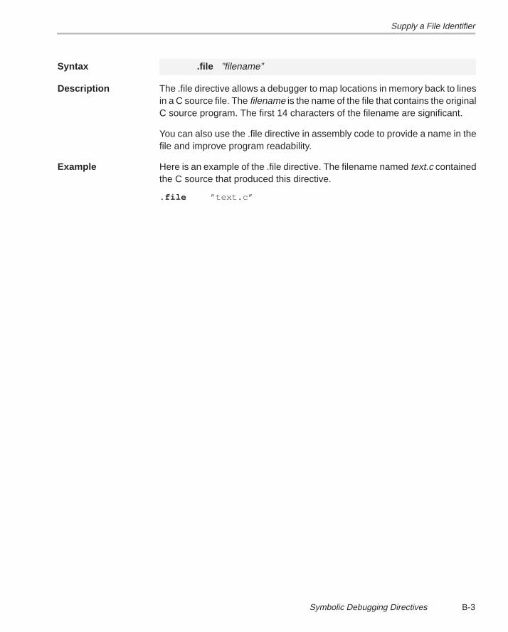
Supply a File Identifier
B-3 Symbolic Debugging Directives
Syntax .file ”filename”
Description The .file directive allows a debugger to map locations in memory back to linesin a C source file. The filename is the name of the file that contains the originalC source program. The first 14 characters of the filename are significant.
You can also use the .file directive in assembly code to provide a name in thefile and improve program readability.
Example Here is an example of the .file directive. The filename named text.c containedthe C source that produced this directive.
.file ”text.c”
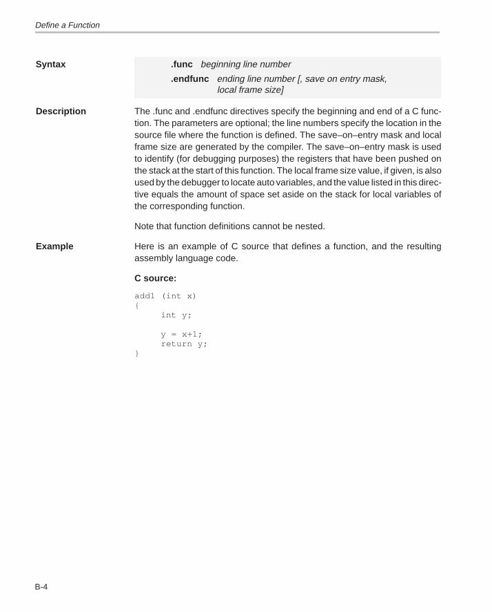
Define a Function
B-4
Syntax .func beginning line number
.endfunc ending line number [, save on entry mask, local frame size]
Description The .func and .endfunc directives specify the beginning and end of a C func-tion. The parameters are optional; the line numbers specify the location in thesource file where the function is defined. The save–on–entry mask and localframe size are generated by the compiler. The save–on–entry mask is usedto identify (for debugging purposes) the registers that have been pushed onthe stack at the start of this function. The local frame size value, if given, is alsoused by the debugger to locate auto variables, and the value listed in this direc-tive equals the amount of space set aside on the stack for local variables ofthe corresponding function.
Note that function definitions cannot be nested.
Example Here is an example of C source that defines a function, and the resultingassembly language code.
C source:
add1 (int x){
int y;
y = x+1;return y;
}
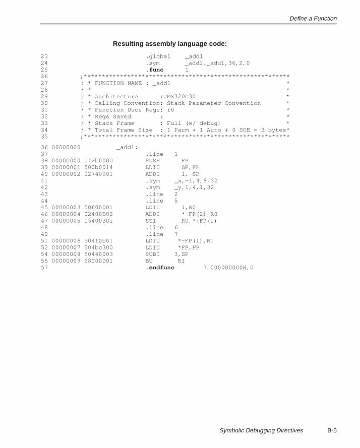
Define a Function
B-5 Symbolic Debugging Directives
Resulting assembly language code:
23 .global _add124 .sym _add1,_add1,36,2,025 .func 126 ;*********************************************************27 ; * FUNCTION NAME : _add1 *28 ; * *29 ; * Architecture :TMS320C30 *30 ; * Calling Convention: Stack Parameter Convention *31 ; * Function Uses Regs: r0 *32 ; * Regs Saved : *33 ; * Stack Frame : Full (w/ debug) *34 ; * Total Frame Size : 1 Parm + 1 Auto + 0 SOE = 3 bytes*35 ;*********************************************************
36 00000000 _add1:37 .line 138 00000000 0f2b0000 PUSH FP39 00000001 500b0014 LDIU SP,FP40 00000002 02740001 ADDI 1, SP41 .sym _x,–1,4,9,3242 .sym _y,1,4,1,3243 .line 244 .line 545 00000003 50600001 LDIU 1,R046 00000004 02400B02 ADDI *–FP(2),R047 00000005 15400301 STI R0,*+FP(1)48 .line 649 .line 751 00000006 50410b01 LDIU *–FP(1),R152 00000007 504bc300 LDIU *FP,FP54 00000008 50440003 SUBI 3,SP55 00000009 68000001 BU R157 .endfunc 7,000000000H,0
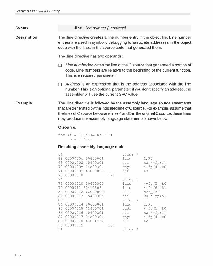
Create a Line Number Entry
B-6
Syntax .line line number [, address]
Description The .line directive creates a line number entry in the object file. Line numberentries are used in symbolic debugging to associate addresses in the objectcode with the lines in the source code that generated them.
The .line directive has two operands:
� Line number indicates the line of the C source that generated a portion ofcode. Line numbers are relative to the beginning of the current function.This is a required parameter.
� Address is an expression that is the address associated with the linenumber. This is an optional parameter; if you don’t specify an address, theassembler will use the current SPC value.
Example The .line directive is followed by the assembly language source statementsthat are generated by the indicated line of C source. For example, assume thatthe lines of C source below are lines 4 and 5 in the original C source; these linesmay produce the assembly language statements shown below.
C source:
for (i = 1; i <= n; ++i) p = p * x;
Resulting assembly language code:
64 .line 468 0000000c 50600001 ldiu 1,R069 0000000d 15400301 sti R0,*+fp(1)70 0000000e 04c00304 cmpi *+fp(4),R071 0000000f 6a090009 bgt L373 00000010 L2:74 .line 578 00000010 50400305 ldiu *+fp(5),R079 0000011 50410306 ldiu *+fp(6),R180 00000012 62000000! call MPY_I3082 00000013 15400305 sti R0,*+fp(5)83 .line 484 00000014 50600001 ldiu 1,R085 00000015 02400301 addi *+fp(1),R086 00000016 15400301 sti R0,*+fp(1)87 00000017 04c00304 cmpi *+fp(4),R088 00000018 6a08fff7 ble L290 00000019 L3:91 .line 6
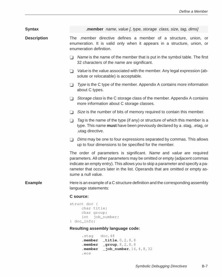
Define a Member
B-7 Symbolic Debugging Directives
Syntax .member name, value [, type, storage class, size, tag, dims]
Description The .member directive defines a member of a structure, union, orenumeration. It is valid only when it appears in a structure, union, orenumeration definition.
� Name is the name of the member that is put in the symbol table. The first32 characters of the name are significant.
� Value is the value associated with the member. Any legal expression (ab-solute or relocatable) is acceptable.
� Type is the C type of the member. Appendix A contains more informationabout C types.
� Storage class is the C storage class of the member. Appendix A containsmore information about C storage classes.
� Size is the number of bits of memory required to contain this member.
� Tag is the name of the type (if any) or structure of which this member is atype. This name must have been previously declared by a .stag, .etag, or.utag directive.
� Dims may be one to four expressions separated by commas. This allowsup to four dimensions to be specified for the member.
The order of parameters is significant. Name and value are requiredparameters. All other parameters may be omitted or empty (adjacent commasindicate an empty entry). This allows you to skip a parameter and specify a pa-rameter that occurs later in the list. Operands that are omitted or empty as-sume a null value.
Example Here is an example of a C structure definition and the corresponding assemblylanguage statements:
C source:
struct doc { char title; char group; int job_number;} doc_info;
Resulting assembly language code:
.stag doc,48 .member _title ,0,2,8,8 .member _group ,8,2,8,8 .member _job_number ,16,4,8,32 .eos
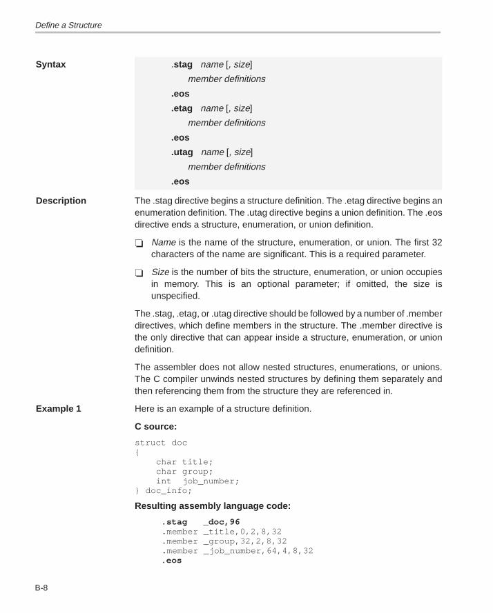
Define a Structure
B-8
Syntax .stag name [, size]
member definitions
.eos
.etag name [, size]
member definitions
.eos
.utag name [, size]
member definitions
.eos
Description The .stag directive begins a structure definition. The .etag directive begins anenumeration definition. The .utag directive begins a union definition. The .eosdirective ends a structure, enumeration, or union definition.
� Name is the name of the structure, enumeration, or union. The first 32characters of the name are significant. This is a required parameter.
� Size is the number of bits the structure, enumeration, or union occupiesin memory. This is an optional parameter; if omitted, the size isunspecified.
The .stag, .etag, or .utag directive should be followed by a number of .memberdirectives, which define members in the structure. The .member directive isthe only directive that can appear inside a structure, enumeration, or uniondefinition.
The assembler does not allow nested structures, enumerations, or unions.The C compiler unwinds nested structures by defining them separately andthen referencing them from the structure they are referenced in.
Example 1 Here is an example of a structure definition.
C source:
struct doc{ char title; char group; int job_number;} doc_info;
Resulting assembly language code:
.stag _doc,96 .member _title,0,2,8,32 .member _group,32,2,8,32 .member _job_number,64,4,8,32 .eos
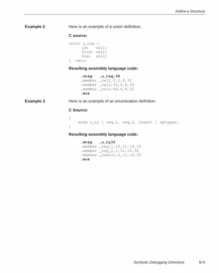
Define a Structure
B-9 Symbolic Debugging Directives
Example 2 Here is an example of a union definition.
C source:
union u_tag {int val1;float val2;char valc;
} valu;
Resulting assembly language code:
.utag _u_tag,96 .member _val1,0,2,8,32 .member _val2,32,4,8,32 .member _valc,64,4,8,32 .eos
Example 3 Here is an example of an enumeration definition.
C Source:
{ enum o_ty { reg_1, reg_2, result } optypes;}
Resulting assembly language code:
.etag _o_ty32 .member _reg_1,10,11,16,32 .member _reg_2,1,11,16,32 .member _result,2,11,16,32 .eos
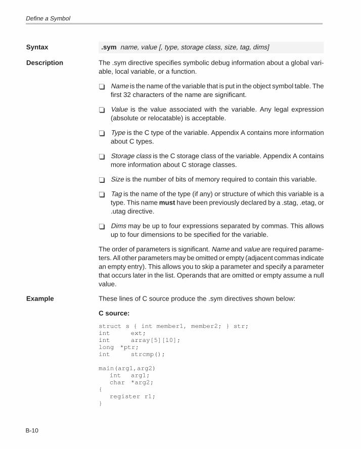
Define a Symbol
B-10
Syntax .sym name, value [, type, storage class, size, tag, dims]
Description The .sym directive specifies symbolic debug information about a global vari-able, local variable, or a function.
� Name is the name of the variable that is put in the object symbol table. Thefirst 32 characters of the name are significant.
� Value is the value associated with the variable. Any legal expression(absolute or relocatable) is acceptable.
� Type is the C type of the variable. Appendix A contains more informationabout C types.
� Storage class is the C storage class of the variable. Appendix A containsmore information about C storage classes.
� Size is the number of bits of memory required to contain this variable.
� Tag is the name of the type (if any) or structure of which this variable is atype. This name must have been previously declared by a .stag, .etag, or.utag directive.
� Dims may be up to four expressions separated by commas. This allowsup to four dimensions to be specified for the variable.
The order of parameters is significant. Name and value are required parame-ters. All other parameters may be omitted or empty (adjacent commas indicatean empty entry). This allows you to skip a parameter and specify a parameterthat occurs later in the list. Operands that are omitted or empty assume a nullvalue.
Example These lines of C source produce the .sym directives shown below:
C source:
struct s { int member1, member2; } str;int ext;int array[5][10];long *ptr;int strcmp();
main(arg1,arg2)int arg1;char *arg2;
{register r1;
}
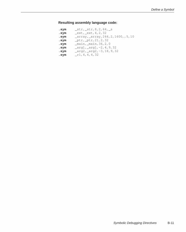
Define a Symbol
B-11 Symbolic Debugging Directives
Resulting assembly language code:
.sym _str,_str,8,2,64,_s
.sym _ext,_ext,4,2,32
.sym _array,_array,244,2,1600,,5,10
.sym _ptr,_ptr,21,2,32
.sym _main,_main,36,2,0
.sym _arg1,_arg1,–2,4,9,32
.sym _arg2,_arg2,–3,18,9,32
.sym _r1,4,4,4,32
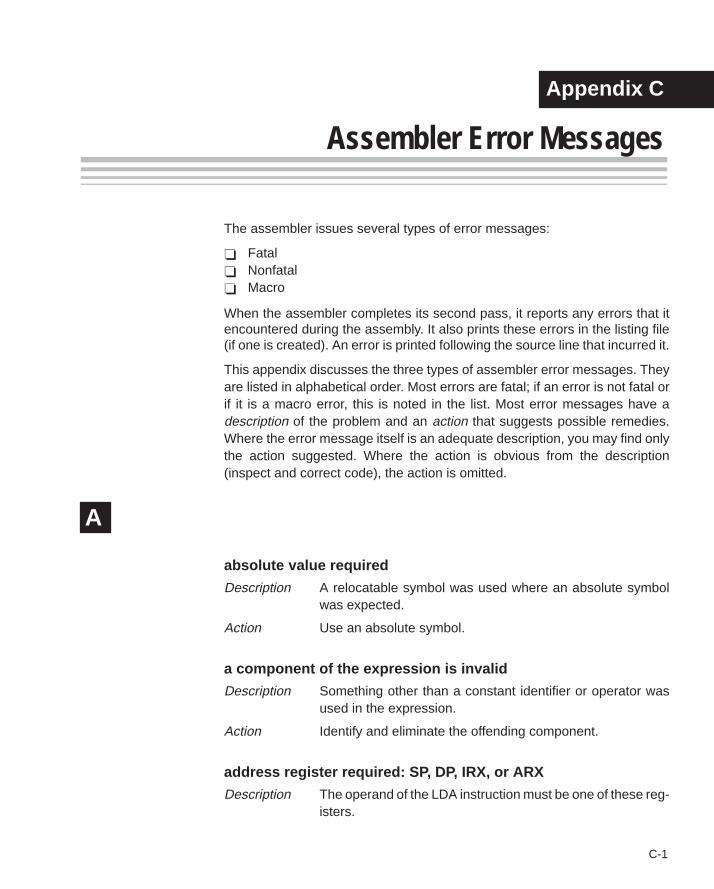
Alphabetical Summary of Debugger Messages
C-1 Chapter Title—Attribute Reference
Appendix A
Assembler Error Messages
The assembler issues several types of error messages:
� Fatal� Nonfatal� Macro
When the assembler completes its second pass, it reports any errors that itencountered during the assembly. It also prints these errors in the listing file(if one is created). An error is printed following the source line that incurred it.
This appendix discusses the three types of assembler error messages. Theyare listed in alphabetical order. Most errors are fatal; if an error is not fatal orif it is a macro error, this is noted in the list. Most error messages have adescription of the problem and an action that suggests possible remedies.Where the error message itself is an adequate description, you may find onlythe action suggested. Where the action is obvious from the description(inspect and correct code), the action is omitted.
A
absolute value required
Description A relocatable symbol was used where an absolute symbolwas expected.
Action Use an absolute symbol.
a component of the expression is invalid
Description Something other than a constant identifier or operator wasused in the expression.
Action Identify and eliminate the offending component.
address register required: SP, DP, IRX, or ARX
Description The operand of the LDA instruction must be one of these reg-isters.
Appendix C
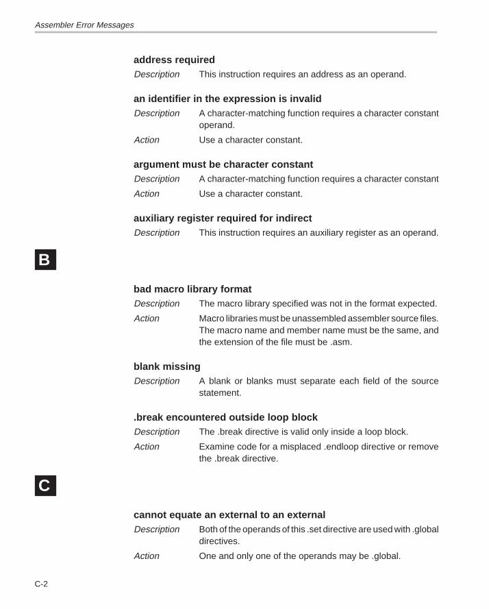
Assembler Error Messages
C-2
address requiredDescription This instruction requires an address as an operand.
an identifier in the expression is invalidDescription A character-matching function requires a character constant
operand.
Action Use a character constant.
argument must be character constantDescription A character-matching function requires a character constant
Action Use a character constant.
auxiliary register required for indirectDescription This instruction requires an auxiliary register as an operand.
B
bad macro library formatDescription The macro library specified was not in the format expected.
Action Macro libraries must be unassembled assembler source files.The macro name and member name must be the same, andthe extension of the file must be .asm.
blank missingDescription A blank or blanks must separate each field of the source
statement.
.break encountered outside loop blockDescription The .break directive is valid only inside a loop block.
Action Examine code for a misplaced .endloop directive or removethe .break directive.
C
cannot equate an external to an externalDescription Both of the operands of this .set directive are used with .global
directives.
Action One and only one of the operands may be .global.
Assembler Error Messages
C-3 Assembler Error Messages
cannot open library
Description A library name specified with the .mlib directive does not existor is already being used.
Action Check spelling, pathname, environment variables, etc.
cannot open listing file : filename
Description The specified filename is inaccessible for some reason.
Action Check spelling, pathname, environment variables, etc.
cannot open object file : filename
Description The specified filename is inaccessible for some reason.
Action Check spelling, pathname, environment variables, etc.
cannot open source file : filename
Description The specified filename is inaccessible for some reason.
Action Check spelling, pathname, environment variables, etc.
cannot redefine register
Description An attempt was made to redefine a register name.
Action Register names cannot be used as labels.
character constant overflows a word
Description Character constants should be limited to four characters.
close ()) missing
Description Mismatched parentheses.
close (]) missing
Description Mismatched brackets.
close quote missing
Description Mismatched or missing quotes.
Action All strings must be enclosed in quotes.
Assembler Error Messages
C-4
comma missing
Description The assembler expected a comma but did not find one.
Action In most cases, the instruction requires more operands thanwere found.
conditional block nesting level exceeded
Description Conditional block nesting cannot exceed 32 levels.
conflicts with previous section definition
Description A section defined with .sect or .usect cannot be redefinedwith the other directive.
Action Change the directives to match or rename one of thesections.
copy file open error
Description A file specified by a .copy directive does not exist or is alreadybeing used.
Action Check spelling, pathname, environment variables, etc.
D
directive only valid if (–a) option used
Description The .setsect and .setsym directives can be used only if the –a(absolute list) option is specified.
Action Remove statements or invoke assembler with –a.
divide by zero
Description An expression or well-defined expression contains invaliddivision.
duplicate definition
Description The symbol appears as an operand of a REF statement, aswell as in the the label field of the source, or the symbolappears more than once in the label field of the source.
Action Examine code for above. Use .newblock to reuse local labels.
Assembler Error Messages
C-5 Assembler Error Messages
duplicate definition of a structure component
Description A structure tag, member, or size symbol was definedelsewhere or used in a .global directive.
E
.else or .elseif needs corresponding .if
Description An .else or .elseif directive was not preceded by an .ifdirective.
empty structure
Description A .struct/.endstruct sequence must have at least onemember.
expansion register required
Description This instruction requires a ’C4x expansion file register.
expression changed values due to branch expansion
Description An expression is dependent on the amount of code betweentwo labels. If the assembler expands a branch in the codebetween these two labels, this expression will evaluate todifferent values in pass1 and pass2.
Action Manually expand any branches between the two labels inyour source code that were automatically expanded by theassembler.
expression not terminated properly
Description Expressions must be delimited by commas, parentheses, orblanks.
expression out of bounds
Description The value specified is too large for this particular instruction ordirective.
extended register R0–R7 required
Description Parallel instructions operate only on these registers.
Assembler Error Messages
C-6
F
filename missing
Description The specified filename cannot be found.
Action Check spelling, pathname, environment variables, etc.
floating-point number not valid in expression
Description A floating-point expression was used where an integerexpression is required.
G
garbage on command line
Description The specified options are illegal or unrecognized.
I
illegal label
Description A label cannot be used for the second instruction of a parallelinstruction pair.
illegal operation in expression
Description This message is usually generated by an illegal combinationof relocatable or external operands.
Action Consult Table 3–2 on page 3-23.
illegal structure definition
Description The .stag/.eos structure definition cannot be nested andcannot contain any debugging directives other than member.
illegal structure member
Description Only directives that reserve space are allowed in structuredefinitions.
Action Consult Directives that Initialize Constants in beginning onpage 4-7.
Assembler Error Messages
C-7 Assembler Error Messages
illegal structure, union, or enumeration tag
Description The operands of .stag must be identifiers.
illegal use of local label
Description Local labels are not allowed in expressions.
incompatible addressing modes
Description Although each operand is correctly formed, the combinationis not valid for this instruction.
index register required for displacement
Description Indirect displacement must be a constant, IR0, or IR1.
indirect address required
Description This instruction expects an indirect address as an operand.
indirect displacement must be 0 or 1
Description This message applies to several 3-operand and parallelinstructions.
indirect displacement out of bounds
Description Range must be 0–255.
invalid binary constant
Description The only valid binary integers are 0 and 1; the constant mustbe suffixed with b or B.
invalid bit-reversed modification
Description Bit-reversed modification is legal only with *AR++(IR0)addressing mode.
invalid branch displacement
Description PC relative branch destination is too far away.
Assembler Error Messages
C-8
invalid circular modification
Description Circular modification legal with *AR++(disp), *AR––(disp),*AR++(IR), or *AR––(IR) only.
invalid decimal constant
Description The only valid decimal integers are 0–9.
Action This error is most commonly caused by failure to use h or H asthe postfix on a hexadecimal number.
invalid expression
Description This may indicate invalid use of a relocatable symbol inarithmetic.
invalid floating-point constant
Description Either the floating-point constant is incorrectly formed, or aninteger constant is used where a floating-point constant isrequired.
invalid hexadecimal constant
Description The only valid hexadecimal digits are the integers are 0–9 andthe letters A–F. The constant must be suffixed with h or H, andit must begin with an integer.
invalid octal constant
Description The only valid octal digits are the integers are 0–8; theconstant must be suffixed with q or Q.
invalid opcode
Description The command field of the source record has an entry that isnot a defined instruction, directive, or macro name.
invalid opcode for selected version
Description An illegal instruction is used for selected CPU. Check the –voption or .version directive.
Assembler Error Messages
C-9 Assembler Error Messages
invalid operand combination–check version
Description An illegal instruction is used for selected CPU. Check the –voption or .version directive.
invalid option
Description An option specified by the .option directive is invalid.
invalid parallel instruction combination
Description These two instructions cannot be combined as one parallelinstruction. Only certain combinations are legal.
invalid symbol qualifier
Description A symbol name is a string of up to 32 alphanumericcharacters (A–Z (either case), 0–9, $, and _) and cannotbegin with a number.
L
label required
Description The flagged directive must have a label.
library not in archive format
Description A file specified with an .mlib directive is not an archive file.
Action Macro libraries must be unassembled assembler source files.The macro name and member name must be the same, andthe extension of the file must be .asm.
local label multiply defined in block
Description Local labels cannot be defined more than once in the currentblock.
Action Use the .newblock directive to reuse local labels in the sameblock.
Assembler Error Messages
C-10
local label not defined in block
Description A local label is used outside the block that it is defined in, or itis not defined at all.
local macro variable is not a valid symbol
Description The operand of .var must be a valid symbol.
Action Consult subsection 6.3.7 on page 6-12.
M
macro parameter is not a valid symbol
Description The macro parameter must be a valid identifier.
Action Section 6.3, beginning on page 6-5, discusses macroparameters.
maximum macro nesting level exceeded
Description The maximum nesting level is 32.
maximum number of copy files exceeded
Description The maximum nesting level for .copy or .include files is 10.
.mexit directive encountered outside macro
Description The .mexit directive is valid only inside macros.
missing .endif directive
Description An .if directive has no matching .endif.
missing .endloop directive
Description A .loop directive has no matching .endloop.
missing .endm directive
Description A .macro directive has no matching .endmacro directive.
Assembler Error Messages
C-11 Assembler Error Messages
missing first half of parallel instruction
Description The || symbol was used on the first statement in a section orthe first instruction was badly formed.
missing macro name
Description The .macro directive requires a name.
missing structure tag
Description The .tag directive requires a symbol name.
N
no include/copy files in macro or loop blocks
Description .include and .copy directives are not allowed inside macros(.macro/.endm) or loop blocks (.loop/.break/.endloop).
no parameters for macro arguments
Description A macro was called with arguments, but no matchingparameters were found in the macro definition.
O
open “(“ expected
Description A built-in function was used improperly, or mismatchedparentheses were found.
operand missing
Action An operand must be supplied.
operand must be an immediate value
Description The operand for this instruction must be an immediate value.
Assembler Error Messages
C-12
operand must be register or indirect
Description For 3-operand or parallel instructions.
out of memory, aborting
Description The assembler has run out of memory and cannot continue.
Action Break the assembly language file into smaller files that can beassembled at one time.
overflow in floating-point constant
Description Floating-point value too large to be represented.
P
pass1/pass2 operand conflict
Description A symbol in the symbol table did not have the same value inpass1 and pass2.
Action This is an internal assembler error. If it occurs repeatedly, theassembler may be corrupt.
positive value required
Description Negative or zero value not allowed.
R
redefinition of local substitution symbol
Description Local substitution symbols can be defined only once in amacro.
register required
Description This instruction requires a register as an operand.
Assembler Error Messages
C-13 Assembler Error Messages
S
string required
Description You must supply a string that is enclosed in double quotes.
string table larger than PC segment size
Description The maximum size for a string table is 64 K bytes.
substitution symbol stack overflow
Description Maximum number of nested substitution symbols is 10.
substitution symbol string too long
Description Maximum substitution symbol length is 200 characters.
subtraction of labels not allowed
Description Subtraction of labels or relationals involving the amount ofcode between labels is not allowed in expressions used insome contexts.
Action Refer to Table 3–2 on page 3-23.
symbol required
Description The .global directive requires a symbol as an operand.
symbol used in both REF and DEF
Description A REFed symbol is already defined.
syntax error
Description An expression is improperly formed.
T
too many local substitution symbols
Description The maximum number of local substitution symbols is �64,000.
Assembler Error Messages
C-14
U
unable to open temp macro library filename
Description The assembler uses a temporary file for holding macrodefinitions. It was unable to create/open this file.
Action Check disk space and protection.
unbalanced symbol table entries
Description Incorrectly scoped .block and .func directives.
undefined structure member
Description A symbol referenced with structure reference notation (a.b) isnot declared in a .struct/.endstruct sequence.
undefined structure tag
Description The operand of .tag must be defined with a .struct directive.
undefined substitution symbol
Description The operand of a substitution symbol must be defined eitheras a macro parameter or with a .asg or .eval directive.
undefined symbol
Description An undefined symbol was used where a well-definedexpression is required.
underflow in floating-point constant
Description Floating-point value is too small to represent.
unexpected .endif encountered
Description An .endif directive was not preceded by a .loop directive.
unexpected .endloop encountered
Description An .endloop directive was not preceded by a .loop directive.
Assembler Error Messages
C-15 Assembler Error Messages
unexpected .endm directive encountered
Description An .endm directive was not preceded by a .macro directive.
unexpected .endstruct directive encountered
Description An .endstruct directive was not preceded by a .structdirective.
unknown model option [–m_], ignored
Description Unrecognized –m option.
**USER ERROR**
Description Output from an .emsg directive.
**USER MESSAGE**
Description Output from a .mmsg directive.
**USER WARNING**
Description Output from a .wmsg directive.
V
value is out of range
Description The value specified is outside the legal range.
.var directive encountered outside macro
Description The .var directive is legal inside macros (.macro/.endm) only.
version number changed
Description The operand of the .version directive does not match aprevious .version directive or the –v command line option.
Assembler Error Messages
C-16
W
warning — block open at end of file
Description A .block or .func directive is missing its corresponding.endblock or .endfunc.
warning — function .sym required before .func
Description A .sym directive defining the function should appear beforethe .func directive.
warning — immediate operand not absolute
Description Immediate operands should be absolute expressions.
Action Refer to Table 3–2 on page 3-23.
warning — line truncated
Description Any characters after the 200th on an input line are ignored.
warning — null string defined
Description An empty string (one whose length = 0) is defined for stringinput for directives that require a null string operand.
warning — register converted to immediate
Description A constant was expected as an operand.
warning — string length exceeds maximum limit
Description The maximum length of the .title directive is 64 characters.
warning — symbol truncated
Description The maximum length for a symbol is eight characters. Theassembler ignores the extra characters.
Assembler Error Messages
C-17 Assembler Error Messages
warning — trailing operand(s)
Description The assembler found fewer or more operands than expectedin the flagged instruction.
warning — value out of range
Description The value specified is outside the legal range.
warning — value truncated
Description The expression given was too large to fit within the instructionopcode or the required number of bits.
Alphabetical Summary of Debugger Messages
D-1 Chapter Title—Attribute Reference
Appendix A
Linker Error Messages
The linker issues several types of error messages:
� Syntax and command errors� Allocation errors� I/O errors
This appendix discusses the three types of errors; they are listedalphabetically within each category. In these listings, the symbol (...)represents the name of an object that the linker is attempting to interact withwhen an error occurs.
Syntax/Command Errors
These errors are caused by incorrect use of linker directives, misuse of aninput expression, or invalid options. Check the syntax of all expressions, andcheck the input directives for accuracy. Review the various options you areusing and check for conflicts.
A
absolute symbol (...) being redefined
Description An absolute symbol cannot be redefined.
adding name (...) to multiple output sections
Description The input section is mentioned twice in the SECTIONSdirective.
ALIGN illegal in this context
Description Alignment of a symbol can be performed only within aSECTIONS directive.
Appendix D
Syntax/Command Errors
D-2
attempt to decrement DOT
Description Statements such as .–= value are illegal. Assignments to dotcan be used only to create holes.
B
bad fill value
Description The fill value must be a 16-bit constant.
binding address for (...) redefined
Description Only one binding value is allowed for each section.
blocking for (...) redefined
Description Only one blocking value is allowed for each section.
C
–c requires fill value of 0 in .cinit (... overridden)
Description C runtime conventions require the .cinit tables to beterminated with 0.
can’t open filename
Description Specified filename cannot be opened for some reason; filedoesn’t exist, wrong file type, etc.
Action Check spelling, pathname, environment variables, etc.
cannot resize (...), section has initialized definition in (...)
Description An initialized input section named .stack or .heap exists,preventing the linker from resizing the section.
Syntax/Command Errors
D-3 Linker Error Messages
cannot specify a page for a section within a GROUP
Description The SECTIONS directive GROUP option forces severaloutput sections to be allocated contiguously. Therefore, youcannot specify a page for a section within a GROUP.
cannot specify both binding and memory area for (...)
Description The two are mutually exclusive. If you wish the code to beplaced at a specific address, use binding only.
command file nesting exceeded with file (...)
Description Command file nesting is allowed up to 16 levels.
E
–e flag does not specify a legal symbol name (...)
Description The –e option requires a valid symbol name as an operand.
entry point other than _c_int00 specified
Description For –c or –cr option only. The runtime conventions of thecompiler assume that _c_int00 is the one and only entry point.
entry point symbol (...) undefined
Description The symbol used with the –e option is not defined.
errors in input – (...) not built
Description Previous errors prevent the creation of an output file.
F
fill value for (...) redefined
Description Only one fill value is allowed per output section. Individualholes can be filled with different values with the sectiondefinition.
Syntax/Command Errors
D-4
I
–i path too long (...)
Description The maximum number of characters in an –i path is 256.
illegal input character
Description There is a control character or other unrecognized characterin the command file.
illegal memory attributes for (...)
Description The attributes must be some combination of R, W, I, and X.
illegal operator in expression
Description Review legal expression operators.
illegal option within SECTIONS
Description The –l (lowercase L) is the only option allowed within aSECTIONS directive.
invalid path specified with –i flag
Description The operand of the –i flag must be a valid file or pathname.
invalid value for –f flag
Description The value for –f must be a 2-byte constant.
invalid value for –heap flag
Description The value for –heap must be a 2-byte constant.
invalid value for –stack flag
Description The value for –stack must be a 2-byte constant.
Syntax/Command Errors
D-5 Linker Error Messages
invalid value for –v flag
Description The value for –v must be a constant.
L
length redefined for memory area (...)
Description Each memory area in a MEMORY directive can have only onelength.
M
–m flag does not specify a valid filename
Description You must specify a valid filename for the file you are writingthe output map file to.
memory area for (...) redefined
Description Only one named memory allocation is allowed for each outputsection.
memory page for (...) redefined
Description Only one page allocation is allowed for each section.
memory attributes redefined for (...)
Description Only one set of memory attributes is allowed for each outputsection.
missing filename on –l; use –l <filename>
Description The –l (lowercase L) option requires the use of a filenameoperand.
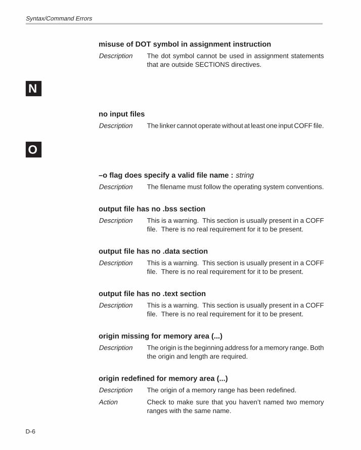
Syntax/Command Errors
D-6
misuse of DOT symbol in assignment instruction
Description The dot symbol cannot be used in assignment statementsthat are outside SECTIONS directives.
N
no input files
Description The linker cannot operate without at least one input COFF file.
O
–o flag does specify a valid file name : string
Description The filename must follow the operating system conventions.
output file has no .bss section
Description This is a warning. This section is usually present in a COFFfile. There is no real requirement for it to be present.
output file has no .data section
Description This is a warning. This section is usually present in a COFFfile. There is no real requirement for it to be present.
output file has no .text section
Description This is a warning. This section is usually present in a COFFfile. There is no real requirement for it to be present.
origin missing for memory area (...)
Description The origin is the beginning address for a memory range. Boththe origin and length are required.
origin redefined for memory area (...)
Description The origin of a memory range has been redefined.
Action Check to make sure that you haven’t named two memoryranges with the same name.
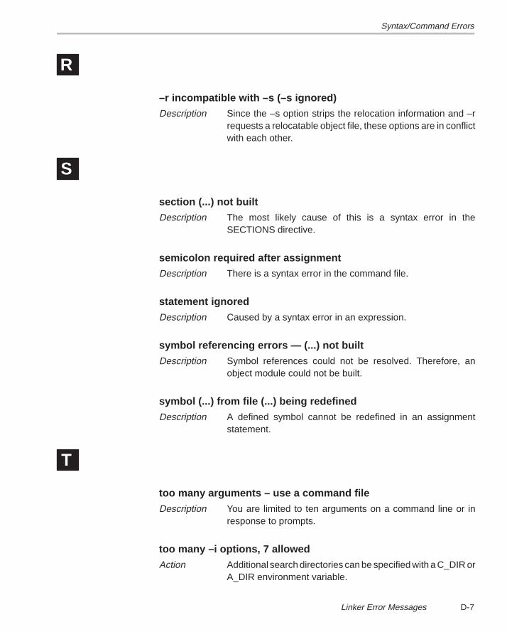
Syntax/Command Errors
D-7 Linker Error Messages
R
–r incompatible with –s (–s ignored)Description Since the –s option strips the relocation information and –r
requests a relocatable object file, these options are in conflictwith each other.
S
section (...) not builtDescription The most likely cause of this is a syntax error in the
SECTIONS directive.
semicolon required after assignmentDescription There is a syntax error in the command file.
statement ignoredDescription Caused by a syntax error in an expression.
symbol referencing errors — (...) not builtDescription Symbol references could not be resolved. Therefore, an
object module could not be built.
symbol (...) from file (...) being redefinedDescription A defined symbol cannot be redefined in an assignment
statement.
T
too many arguments – use a command fileDescription You are limited to ten arguments on a command line or in
response to prompts.
too many –i options, 7 allowedAction Additional search directories can be specified with a C_DIR or
A_DIR environment variable.
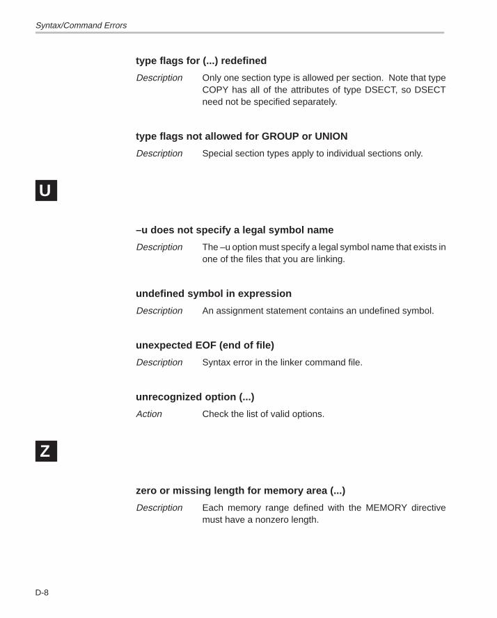
Syntax/Command Errors
D-8
type flags for (...) redefined
Description Only one section type is allowed per section. Note that typeCOPY has all of the attributes of type DSECT, so DSECTneed not be specified separately.
type flags not allowed for GROUP or UNION
Description Special section types apply to individual sections only.
U
–u does not specify a legal symbol name
Description The –u option must specify a legal symbol name that exists inone of the files that you are linking.
undefined symbol in expression
Description An assignment statement contains an undefined symbol.
unexpected EOF (end of file)
Description Syntax error in the linker command file.
unrecognized option (...)
Action Check the list of valid options.
Z
zero or missing length for memory area (...)
Description Each memory range defined with the MEMORY directivemust have a nonzero length.
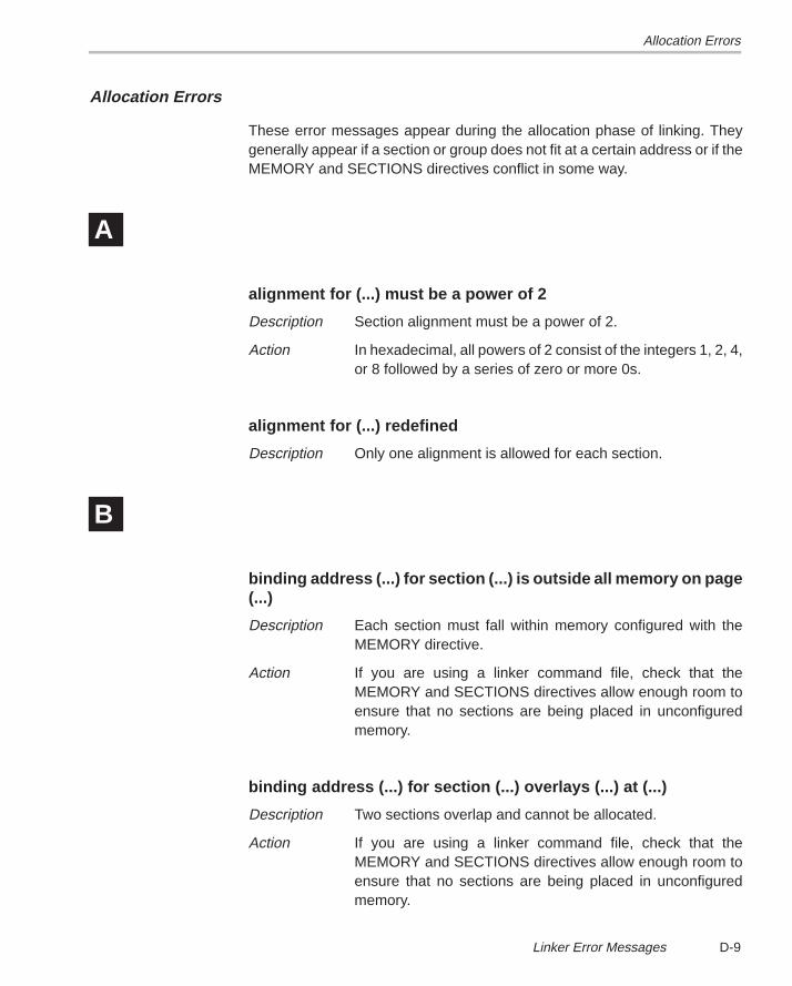
Allocation Errors
D-9 Linker Error Messages
Allocation Errors
These error messages appear during the allocation phase of linking. Theygenerally appear if a section or group does not fit at a certain address or if theMEMORY and SECTIONS directives conflict in some way.
A
alignment for (...) must be a power of 2
Description Section alignment must be a power of 2.
Action In hexadecimal, all powers of 2 consist of the integers 1, 2, 4,or 8 followed by a series of zero or more 0s.
alignment for (...) redefined
Description Only one alignment is allowed for each section.
B
binding address (...) for section (...) is outside all memory on page(...)
Description Each section must fall within memory configured with theMEMORY directive.
Action If you are using a linker command file, check that theMEMORY and SECTIONS directives allow enough room toensure that no sections are being placed in unconfiguredmemory.
binding address (...) for section (...) overlays (...) at (...)
Description Two sections overlap and cannot be allocated.
Action If you are using a linker command file, check that theMEMORY and SECTIONS directives allow enough room toensure that no sections are being placed in unconfiguredmemory.
Allocation Errors
D-10
binding address (...) incompatible with alignment for section (...)
Description The section has an alignment requirement from an .aligndirective or previous link. The binding address violates thisrequirement.
blocking for (...) must be a power of 2
Description Section blocking must be a power of 2.
Action In hexadecimal, all powers of 2 consist of the integers 1, 2, 4,or 8 followed by a series of zero or more 0s.
C
can’t align a section within GROUP – (...) not aligned
Description The entire GROUP is treated as one unit, so the GROUP canbe aligned or bound to an address, but the sections making upthe GROUP cannot be handled individually.
can’t align within UNION – section (...) not aligned
Description The entire UNION is treated as one unit, so the UNION can bealigned or bound to an address, but the sections making upthe UNION cannot be handled individually.
can’t allocate (...), size ... (page ...)
Description A section can’t be allocated, because no configured memoryarea exists that is large enough to hold it.
Action If you are using a linker command file, check that theMEMORY and SECTIONS directives allow enough room toensure that no sections are being placed in unconfiguredmemory.
Allocation Errors
D-11 Linker Error Messages
L
load address for uninitialized section (...) ignored
Description Uninitialized sections have no load addresses—only runaddresses.
load address for UNION ignored
Description UNION refers only to the section’s run address.
load allocation required for uninitialized UNION member (...)
Description UNIONs refer to runtime allocation only. You must specify theload address for all sections within a UNION separately.
M
memory types (...) and (...) on page (...) overlap
Description Memory ranges on the same page cannot overlap.
Action If you are using a linker command file, check that theMEMORY and SECTIONS directives allow enough room toensure that no sections are being placed in unconfiguredmemory.
N
no allocation allowed for uninitialized UNION member
Description An uninitialized section with a UNION gets its run allocationfrom the UNION and has no load address, so no allocation isvalid for the member.
no allocation allowed with a GROUP–allocation for section (...)ignored
Description The entire group is treated as one unit, so the group can bealigned or bound to an address, but the sections making upthe group cannot be handled individually.
Allocation Errors
D-12
no load address specified for (...); using run address
Description If an initialized section has a run address only, the section isallocated to run and load at the same address.
no run allocation allowed for union member (...)
Description A UNION defines the run address for all of its members;therefore, individual run allocations are illegal.
O
output file (...) not executable
Description The output file created may have unresolved symbols or otherproblems stemming from other errors. This condition is notfatal.
P
PC-relative displacement overflow at address (...) in file (...)
Description relocation of a PC-relative jump resulted in a jumpdisplacement too large to encode in the instruction.
S
section (...) at (...) overlays at address (...)
Description The two sections overlap and cannot be allocated.
Action If you are using a linker command file, check that theMEMORY and SECTIONS directives allow enough room toensure that no sections overlap.
section (...) enters unconfigured memory at address (...)
Description A section can’t be allocated because no configured memoryarea exists that is large enough to hold it.
Action If you are using a linker command file, check that theMEMORY and SECTIONS directives allow enough room toensure that no sections are being placed in unconfiguredmemory.
Allocation Errors
D-13 Linker Error Messages
section (...) not found
Description An input section specified in a SECTIONS directive was notfound in the input file.
section (...) won’t fit into configured memory
Description A section can’t be allocated, because no configured memoryarea exists that is large enough to hold it.
Action If you are using a linker command file, check that theMEMORY and SECTIONS directives allow enough room toensure that no sections are being placed in unconfiguredmemory.
U
undefined symbol (...) first referenced in file (...)
Description Unless the –r option is used, the linker requires that all refer-enced symbols be defined. This condition prevents the cre-ation of an executable output file.
Action Link using the –r option or define the symbol.
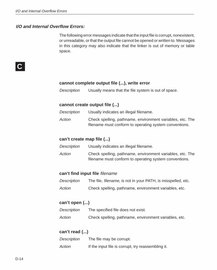
I/O and Internal Overflow Errors
D-14
I/O and Internal Overflow Errors:
The following error messages indicate that the input file is corrupt, nonexistent,or unreadable, or that the output file cannot be opened or written to. Messagesin this category may also indicate that the linker is out of memory or tablespace.
C
cannot complete output file (...), write error
Description Usually means that the file system is out of space.
cannot create output file (...)
Description Usually indicates an illegal filename.
Action Check spelling, pathname, environment variables, etc. Thefilename must conform to operating system conventions.
can’t create map file (...)
Description Usually indicates an illegal filename.
Action Check spelling, pathname, environment variables, etc. Thefilename must conform to operating system conventions.
can’t find input file filename
Description The file, filename, is not in your PATH, is misspelled, etc.
Action Check spelling, pathname, environment variables, etc.
can’t open (...)
Description The specified file does not exist.
Action Check spelling, pathname, environment variables, etc.
can’t read (...)
Description The file may be corrupt.
Action If the input file is corrupt, try reassembling it.
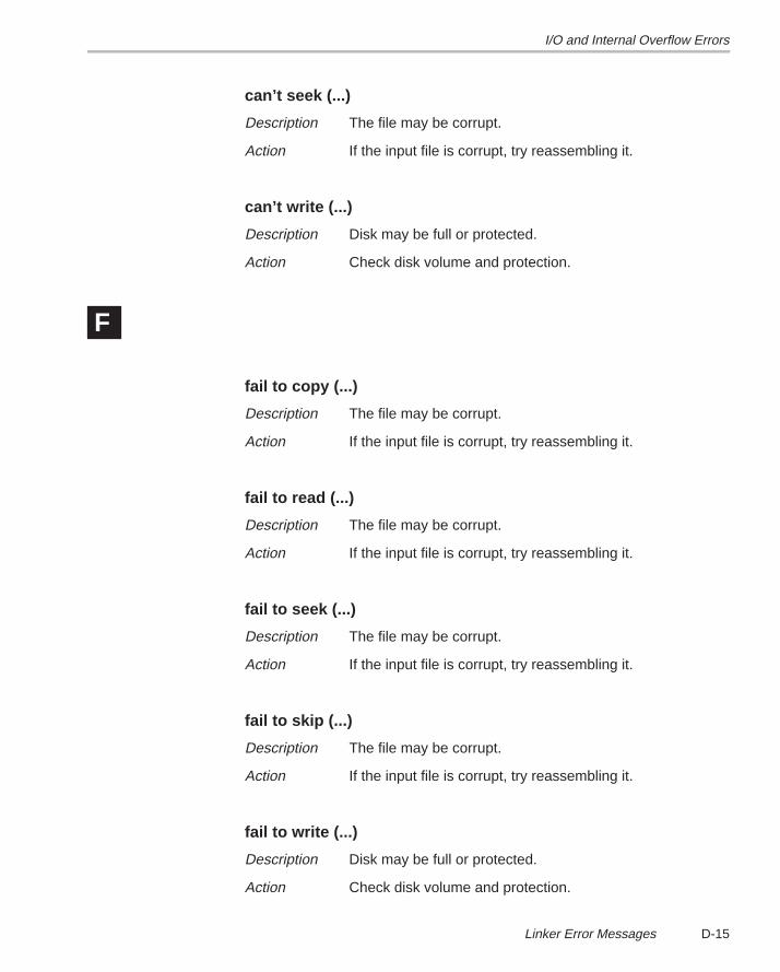
I/O and Internal Overflow Errors
D-15 Linker Error Messages
can’t seek (...)
Description The file may be corrupt.
Action If the input file is corrupt, try reassembling it.
can’t write (...)
Description Disk may be full or protected.
Action Check disk volume and protection.
F
fail to copy (...)
Description The file may be corrupt.
Action If the input file is corrupt, try reassembling it.
fail to read (...)
Description The file may be corrupt.
Action If the input file is corrupt, try reassembling it.
fail to seek (...)
Description The file may be corrupt.
Action If the input file is corrupt, try reassembling it.
fail to skip (...)
Description The file may be corrupt.
Action If the input file is corrupt, try reassembling it.
fail to write (...)
Description Disk may be full or protected.
Action Check disk volume and protection.
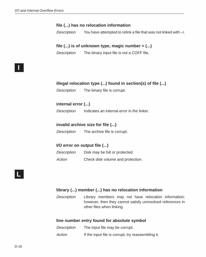
I/O and Internal Overflow Errors
D-16
file (...) has no relocation information
Description You have attempted to relink a file that was not linked with –r.
file (...) is of unknown type, magic number = (...)
Description The binary input file is not a COFF file.
I
illegal relocation type (...) found in section(s) of file (...)
Description The binary file is corrupt.
internal error (...)
Description Indicates an internal error in the linker.
invalid archive size for file (...)
Description The archive file is corrupt.
I/O error on output file (...)
Description Disk may be full or protected.
Action Check disk volume and protection.
L
library (...) member (...) has no relocation information
Description Library members may not have relocation information;however, then they cannot satisfy unresolved references inother files when linking.
line number entry found for absolute symbol
Description The input file may be corrupt.
Action If the input file is corrupt, try reassembling it.
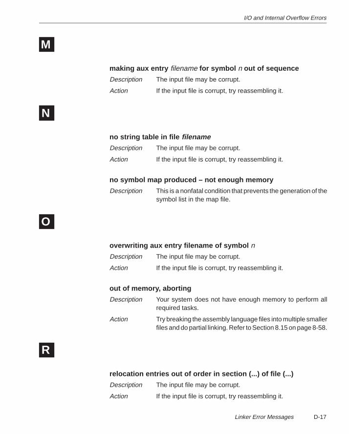
I/O and Internal Overflow Errors
D-17 Linker Error Messages
M
making aux entry filename for symbol n out of sequence
Description The input file may be corrupt.
Action If the input file is corrupt, try reassembling it.
N
no string table in file filenameDescription The input file may be corrupt.
Action If the input file is corrupt, try reassembling it.
no symbol map produced – not enough memory
Description This is a nonfatal condition that prevents the generation of thesymbol list in the map file.
O
overwriting aux entry filename of symbol n
Description The input file may be corrupt.
Action If the input file is corrupt, try reassembling it.
out of memory, aborting
Description Your system does not have enough memory to perform allrequired tasks.
Action Try breaking the assembly language files into multiple smallerfiles and do partial linking. Refer to Section 8.15 on page 8-58.
R
relocation entries out of order in section (...) of file (...)
Description The input file may be corrupt.
Action If the input file is corrupt, try reassembling it.
I/O and Internal Overflow Errors
D-18
relocation symbol not found: index (...), section (...), file (...)
Description The input file may be corrupt.
Action If the input file is corrupt, try reassembling it.
S
seek to (...) failed
Description The input file may be corrupt.
Action If the input file is corrupt, try reassembling it.
T
too few symbol names in string table for archive n
Description The archive file may be corrupt.
Action If the input file is corrupt, try recreating the archive.
Running Title—Attribute Reference
E-1 Chapter Title—Attribute Reference
Appendix A
Hex Conversion Utility Examples
This section contains eight examples that will illustrate the development ofcommand files for a variety of memory systems and situations.
Topic Page
E.1 Building a Command File for Two 16-Bit EPROMS E-3. . . . . . . . . . . . . . . .
E.2 Building a Command File for Booting From the ’C4xCommunications Port E-9. . . . . . . . . . . . . . . . . . . . . . . . . . . . . . . . . . . . . . . . .
E.3 Building a Command File to Convert Code for a ’C32 E-15. . . . . . . . . . . .
E.4 Building a Command File for a Four 8-Bit EPROM System E-20. . . . . . .
E.5 Avoiding Holes Between Multiple Sections E-21. . . . . . . . . . . . . . . . . . . . .
E.6 Building a Command File for a ’C31 Serial Port Boot Load E-23. . . . . . .
E.7 Dealing With Three Different Addresses E-24. . . . . . . . . . . . . . . . . . . . . . . .
E.8 Building a Command File to Generate a Boot Table for a ’C32 E-26. . . .
Appendix E
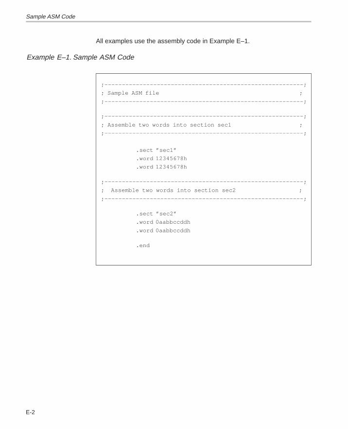
Sample ASM Code
E-2
All examples use the assembly code in Example E–1.
Example E–1. Sample ASM Code
;–––––––––––––––––––––––––––––––––––––––––––––––––––––––––;
; Sample ASM file ;
;–––––––––––––––––––––––––––––––––––––––––––––––––––––––––;
;–––––––––––––––––––––––––––––––––––––––––––––––––––––––––;
; Assemble two words into section sec1 ;
;–––––––––––––––––––––––––––––––––––––––––––––––––––––––––;
.sect ”sec1”
.word 12345678h
.word 12345678h
;–––––––––––––––––––––––––––––––––––––––––––––––––––––––––;
; Assemble two words into section sec2 ;
;–––––––––––––––––––––––––––––––––––––––––––––––––––––––––;
.sect ”sec2”
.word 0aabbccddh
.word 0aabbccddh
.end
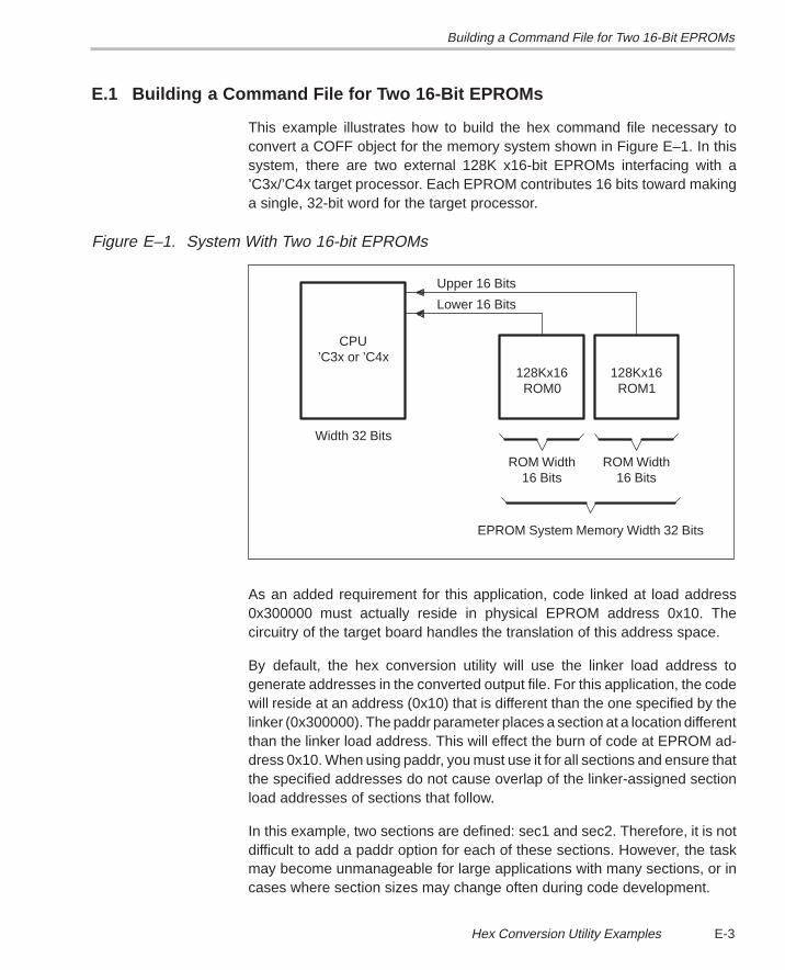
Building a Command File for Two 16-Bit EPROMs
E-3 Hex Conversion Utility Examples
E.1 Building a Command File for Two 16-Bit EPROMs
This example illustrates how to build the hex command file necessary toconvert a COFF object for the memory system shown in Figure E–1. In thissystem, there are two external 128K x16-bit EPROMs interfacing with a’C3x/’C4x target processor. Each EPROM contributes 16 bits toward makinga single, 32-bit word for the target processor.
Figure E–1. System With Two 16-bit EPROMs
Lower 16 Bits
Upper 16 Bits
EPROM System Memory Width 32 Bits
ROM Width16 Bits16 Bits
ROM Width
ROM1128Kx16
ROM0128Kx16
Width 32 Bits
’C3x or ’C4xCPU
As an added requirement for this application, code linked at load address0x300000 must actually reside in physical EPROM address 0x10. Thecircuitry of the target board handles the translation of this address space.
By default, the hex conversion utility will use the linker load address togenerate addresses in the converted output file. For this application, the codewill reside at an address (0x10) that is different than the one specified by thelinker (0x300000). The paddr parameter places a section at a location differentthan the linker load address. This will effect the burn of code at EPROM ad-dress 0x10. When using paddr, you must use it for all sections and ensure thatthe specified addresses do not cause overlap of the linker-assigned sectionload addresses of sections that follow.
In this example, two sections are defined: sec1 and sec2. Therefore, it is notdifficult to add a paddr option for each of these sections. However, the taskmay become unmanageable for large applications with many sections, or incases where section sizes may change often during code development.
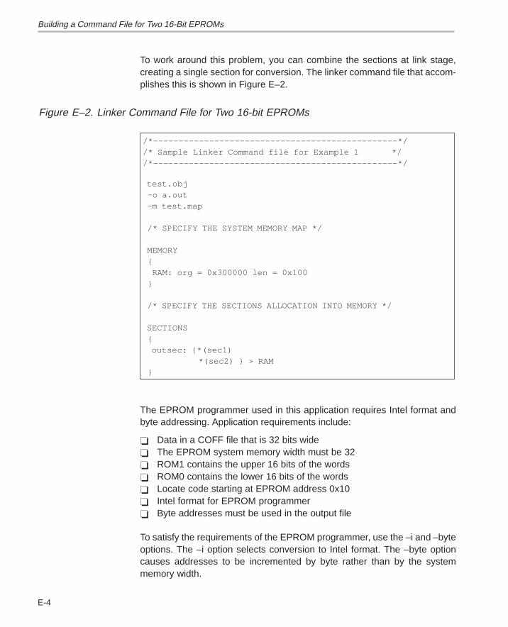
Building a Command File for Two 16-Bit EPROMs
E-4
To work around this problem, you can combine the sections at link stage,creating a single section for conversion. The linker command file that accom-plishes this is shown in Figure E–2.
Figure E–2. Linker Command File for Two 16-bit EPROMs
/*––––––––––––––––––––––––––––––––––––––––––––––––*//* Sample Linker Command file for Example 1 *//*––––––––––––––––––––––––––––––––––––––––––––––––*/
test.obj –o a.out –m test.map /* SPECIFY THE SYSTEM MEMORY MAP */ MEMORY { RAM: org = 0x300000 len = 0x100 } /* SPECIFY THE SECTIONS ALLOCATION INTO MEMORY */ SECTIONS { outsec: {*(sec1)
*(sec2) } > RAM }
The EPROM programmer used in this application requires Intel format andbyte addressing. Application requirements include:
� Data in a COFF file that is 32 bits wide� The EPROM system memory width must be 32� ROM1 contains the upper 16 bits of the words� ROM0 contains the lower 16 bits of the words� Locate code starting at EPROM address 0x10� Intel format for EPROM programmer� Byte addresses must be used in the output file
To satisfy the requirements of the EPROM programmer, use the –i and –byteoptions. The –i option selects conversion to Intel format. The –byte optioncauses addresses to be incremented by byte rather than by the systemmemory width.
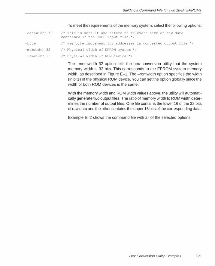
Building a Command File for Two 16-Bit EPROMs
E-5 Hex Conversion Utility Examples
To meet the requirements of the memory system, select the following options:
–datawidth 32 /* This is default and refers to relevant size of raw data contained in the COFF input file */
–byte /* use byte increment for addresses in converted output file */
–memwidth 32 /* Physical width of EPROM system */
–romwidth 16 /* Physical width of ROM device */
The –memwidth 32 option tells the hex conversion utility that the systemmemory width is 32 bits. This corresponds to the EPROM system memorywidth, as described in Figure E–1. The –romwidth option specifies the width(in bits) of the physical ROM device. You can set the option globally since thewidth of both ROM devices is the same.
With the memory width and ROM width values above, the utility will automati-cally generate two output files. The ratio of memory width to ROM width deter-mines the number of output files. One file contains the lower 16 of the 32 bitsof raw data and the other contains the upper 16 bits of the corresponding data.
Example E–2 shows the command file with all of the selected options.
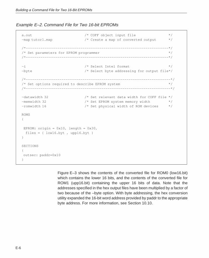
Building a Command File for Two 16-Bit EPROMs
E-6
Example E–2. Command File for Two 16-bit EPROMs
a.out /* COFF object input file */–map tutor1.mxp /* Create a map of converted output */
/*––––––––––––––––––––––––––––––––––––––––––––––––––––––––––––––––––––*//* Set parameters for EPROM programmer *//*––––––––––––––––––––––––––––––––––––––––––––––––––––––––––––––––––––*/ –i /* Select Intel format */–byte /* Select byte addressing for output file*/
/*–––––––––––––––––––––––––––––––––––––––––––––––––––––––––––––––––––––*//* Set options required to describe EPROM system *//*–––––––––––––––––––––––––––––––––––––––––––––––––––––––––––––––––––––*/
–datawidth 32 /* Set relevant data width for COFF file */–memwidth 32 /* Set EPROM system memory width */–romwidth 16 /* Set physical width of ROM devices */
ROMS{ EPROM: origin = 0x10, length = 0x30, files = { low16.byt , upp16.byt }}
SECTIONS{ outsec: paddr=0x10}
Figure E–3 shows the contents of the converted file for ROM0 (low16.bit)which contains the lower 16 bits, and the contents of the converted file forROM1 (upp16.bit) containing the upper 16 bits of data. Note that theaddresses specified in the hex output files have been multiplied by a factor oftwo because of the –byte option. With byte addressing, the hex conversionutility expanded the 16-bit word address provided by paddr to the appropriatebyte address. For more information, see Section 10.10.
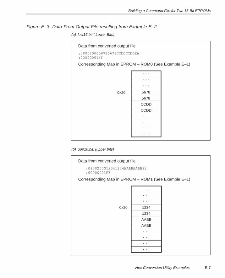
Building a Command File for Two 16-Bit EPROMs
E-7 Hex Conversion Utility Examples
Figure E–3. Data From Output File resulting from Example E–2
(a) low16.bit:( Lower Bits)
Data from converted output file
:0800200056785678CCDDCCDDEA:00000001FF
Corresponding Map in EPROM – ROM0 (See Example E–1)
CCDD
CCDD
5678
56780x20
(b) upp16.bit: (upper bits)
0x20
AABB
AABB
1234
1234
Data from converted output file
:0800200012341234AABBAABB82:00000001FF
Corresponding Map in EPROM – ROM1 (See Example E–1)
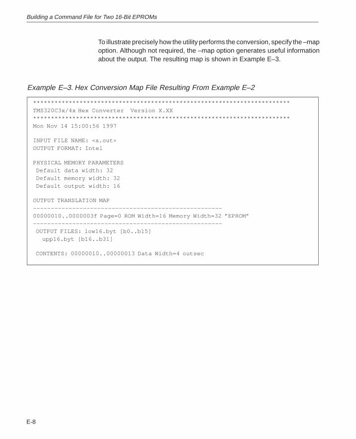
Building a Command File for Two 16-Bit EPROMs
E-8
To illustrate precisely how the utility performs the conversion, specify the –mapoption. Although not required, the –map option generates useful informationabout the output. The resulting map is shown in Example E–3.
Example E–3. Hex Conversion Map File Resulting From Example E–2
************************************************************************TMS320C3x/4x Hex Converter Version X.XX ************************************************************************Mon Nov 14 15:00:56 1997
INPUT FILE NAME: <a.out>OUTPUT FORMAT: Intel
PHYSICAL MEMORY PARAMETERS Default data width: 32 Default memory width: 32 Default output width: 16
OUTPUT TRANSLATION MAP–––––––––––––––––––––––––––––––––––––––––––––––––––––00000010..0000003f Page=0 ROM Width=16 Memory Width=32 ”EPROM”––––––––––––––––––––––––––––––––––––––––––––––––––––– OUTPUT FILES: low16.byt [b0..b15] upp16.byt [b16..b31]
CONTENTS: 00000010..00000013 Data Width=4 outsec
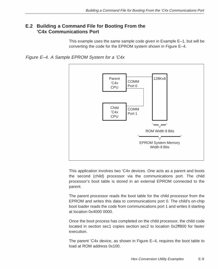
Building a Command File for Booting From the ’C4x Communications Port
E-9 Hex Conversion Utility Examples
E.2 Building a Command File for Booting From the ’C4x Communications Port
This example uses the same sample code given in Example E–1, but will beconverting the code for the EPROM system shown in Figure E–4.
Figure E–4. A Sample EPROM System for a ’C4x
Port 0COMM
Port 1COMM
Width 8 BitsEPROM System Memory
ROM Width 8 Bits
CPU’C4xChild
128Kx8
CPU’C4x
Parent
This application involves two ’C4x devices. One acts as a parent and bootsthe second (child) processor via the communications port. The childprocessor’s boot table is stored in an external EPROM connected to theparent.
The parent processor reads the boot table for the child processor from theEPROM and writes this data to communications port 0. The child’s on-chipboot loader reads the code from communications port 1 and writes it startingat location 0x4000 0000.
Once the boot process has completed on the child processor, the child codelocated in section sec1 copies section sec2 to location 0x2ff800 for fasterexecution.
The parent ’C4x device, as shown in Figure E–4, requires the boot table toload at ROM address 0x100.
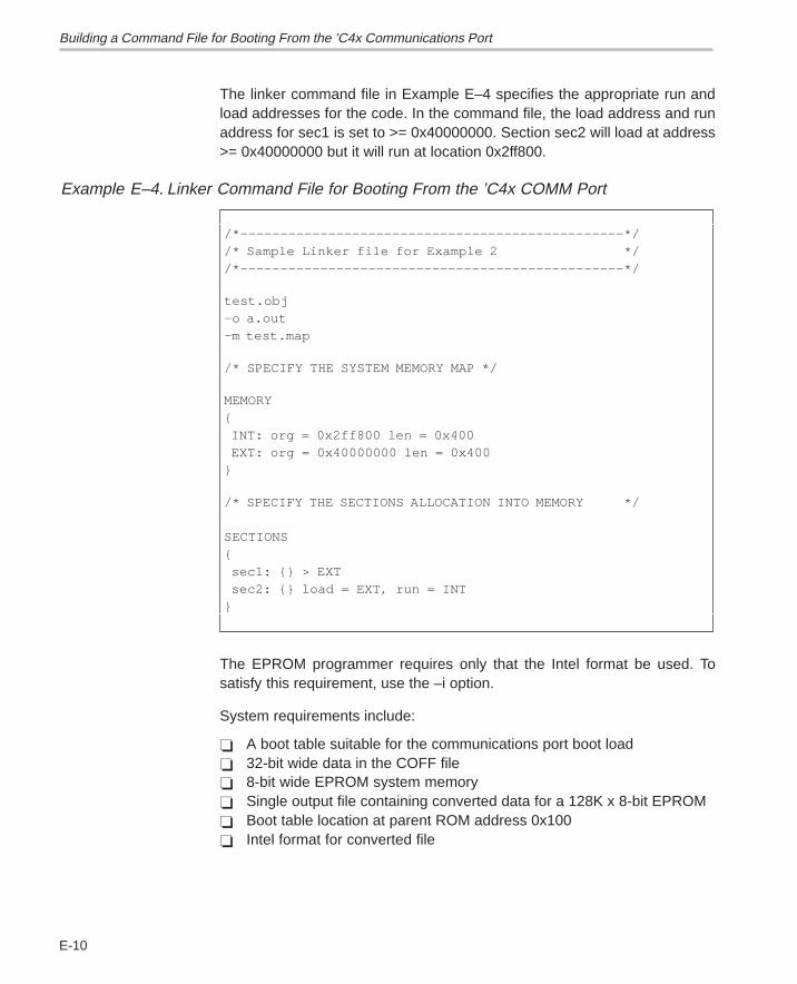
Building a Command File for Booting From the ’C4x Communications Port
E-10
The linker command file in Example E–4 specifies the appropriate run andload addresses for the code. In the command file, the load address and runaddress for sec1 is set to >= 0x40000000. Section sec2 will load at address>= 0x40000000 but it will run at location 0x2ff800.
Example E–4. Linker Command File for Booting From the ’C4x COMM Port
/*––––––––––––––––––––––––––––––––––––––––––––––––*//* Sample Linker file for Example 2 *//*––––––––––––––––––––––––––––––––––––––––––––––––*/
test.obj–o a.out–m test.map
/* SPECIFY THE SYSTEM MEMORY MAP */
MEMORY{ INT: org = 0x2ff800 len = 0x400 EXT: org = 0x40000000 len = 0x400 }
/* SPECIFY THE SECTIONS ALLOCATION INTO MEMORY */ SECTIONS{ sec1: {} > EXT sec2: {} load = EXT, run = INT}
The EPROM programmer requires only that the Intel format be used. Tosatisfy this requirement, use the –i option.
System requirements include:
� A boot table suitable for the communications port boot load� 32-bit wide data in the COFF file� 8-bit wide EPROM system memory� Single output file containing converted data for a 128K x 8-bit EPROM� Boot table location at parent ROM address 0x100� Intel format for converted file
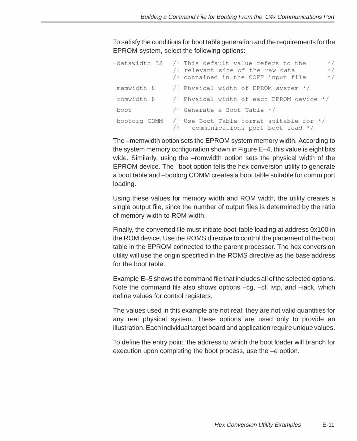
Building a Command File for Booting From the ’C4x Communications Port
E-11 Hex Conversion Utility Examples
To satisfy the conditions for boot table generation and the requirements for theEPROM system, select the following options:
–datawidth 32 /* This default value refers to the *//* relevant size of the raw data *//* contained in the COFF input file */
–memwidth 8 /* Physical width of EPROM system */
–romwidth 8 /* Physical width of each EPROM device */
–boot /* Generate a Boot Table */
–bootorg COMM /* Use Boot Table format suitable for *//* communications port boot load */
The –memwidth option sets the EPROM system memory width. According tothe system memory configuration shown in Figure E–4, this value is eight bitswide. Similarly, using the –romwidth option sets the physical width of theEPROM device. The –boot option tells the hex conversion utility to generatea boot table and –bootorg COMM creates a boot table suitable for comm portloading.
Using these values for memory width and ROM width, the utility creates asingle output file, since the number of output files is determined by the ratioof memory width to ROM width.
Finally, the converted file must initiate boot-table loading at address 0x100 inthe ROM device. Use the ROMS directive to control the placement of the boottable in the EPROM connected to the parent processor. The hex conversionutility will use the origin specified in the ROMS directive as the base addressfor the boot table.
Example E–5 shows the command file that includes all of the selected options.Note the command file also shows options –cg, –cl, ivtp, and –iack, whichdefine values for control registers.
The values used in this example are not real; they are not valid quantities forany real physical system. These options are used only to provide anillustration. Each individual target board and application require unique values.
To define the entry point, the address to which the boot loader will branch forexecution upon completing the boot process, use the –e option.
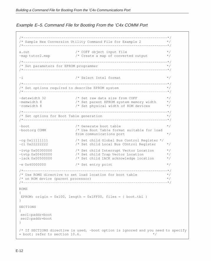
Building a Command File for Booting From the ’C4x Communications Port
E-12
Example E–5. Command File for Booting From the ’C4x COMM Port
/*––––––––––––––––––––––––––––––––––––––––––––––––––––––––––––––––––––*//* Sample Hex Conversion Utility Command File for Example 2 *//*––––––––––––––––––––––––––––––––––––––––––––––––––––––––––––––––––––*/
a.out /* COFF object input file */–map tutor2.mxp /* Create a map of converted output */
/*––––––––––––––––––––––––––––––––––––––––––––––––––––––––––––––––––––*//* Set parameters for EPROM programmer *//*––––––––––––––––––––––––––––––––––––––––––––––––––––––––––––––––––––*/ –i /* Select Intel format */
/*––––––––––––––––––––––––––––––––––––––––––––––––––––––––––––––––––––*//* Set options required to describe EPROM system *//*––––––––––––––––––––––––––––––––––––––––––––––––––––––––––––––––––––*/
–datawidth 32 /* Set raw data size from COFF */–memwidth 8 /* Set parent EPROM system memory width */–romwidth 8 /* Set physical width of ROM devices */
/*––––––––––––––––––––––––––––––––––––––––––––––––––––––––––––––––––––*//* Set options for Boot Table generation *//*––––––––––––––––––––––––––––––––––––––––––––––––––––––––––––––––––––*/
–boot /* Generate boot table */–bootorg COMM /* Use Boot Table format suitable for load
from communications port */
–cg 0x11111111 /* Set child Global Bus Control Register */–cl 0x22222222 /* Set child Local Bus COntrol Register */
–ivtp 0x00300000 /* Set child Interrupt Vector Location */–tvtp 0x00400000 /* Set child Trap Vector Location */–iack 0x00500000 /* Set child IACK acknowledge location */
–e 0x40000000 /* Set entry point */
/*––––––––––––––––––––––––––––––––––––––––––––––––––––––––––––––––––––*//* Use ROMS directive to set load location for boot table *//* on ROM device (parent processor) *//*––––––––––––––––––––––––––––––––––––––––––––––––––––––––––––––––––––*/
ROMS{ EPROM: origin = 0x100, length = 0x1FF00, files = { boot.tbl }}
SECTIONS{ sec1:paddr=boot sec2:paddr=boot}
/* If SECTIONS directive is used, –boot option is ignored and you need to specify= boot; refer to section 10.6. */
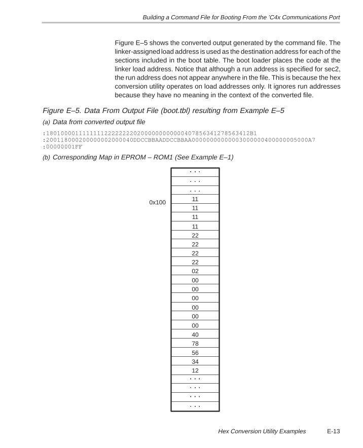
Building a Command File for Booting From the ’C4x Communications Port
E-13 Hex Conversion Utility Examples
Figure E–5 shows the converted output generated by the command file. Thelinker-assigned load address is used as the destination address for each of thesections included in the boot table. The boot loader places the code at thelinker load address. Notice that although a run address is specified for sec2,the run address does not appear anywhere in the file. This is because the hexconversion utility operates on load addresses only. It ignores run addressesbecause they have no meaning in the context of the converted file.
Figure E–5. Data From Output File (boot.tbl) resulting from Example E–5
(a) Data from converted output file
:18010000111111112222222202000000000000407856341278563412B1:200118000200000002000040DDCCBBAADDCCBBAA00000000000003000000400000005000A7:00000001FF
(b) Corresponding Map in EPROM – ROM1 (See Example E–1)
0x100
12
34
56
78
40
00
00
00
00
00
22
22
22
11
11
11
00
02
22
11
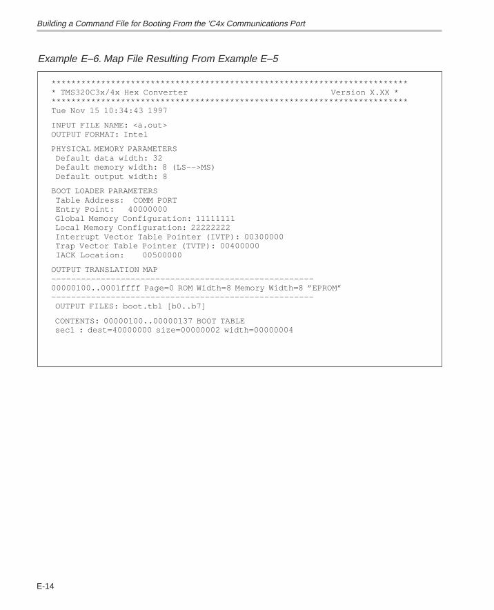
Building a Command File for Booting From the ’C4x Communications Port
E-14
Example E–6. Map File Resulting From Example E–5
************************************************************************* TMS320C3x/4x Hex Converter Version X.XX *************************************************************************Tue Nov 15 10:34:43 1997
INPUT FILE NAME: <a.out>OUTPUT FORMAT: Intel
PHYSICAL MEMORY PARAMETERS Default data width: 32 Default memory width: 8 (LS––>MS) Default output width: 8
BOOT LOADER PARAMETERS Table Address: COMM PORT Entry Point: 40000000 Global Memory Configuration: 11111111 Local Memory Configuration: 22222222 Interrupt Vector Table Pointer (IVTP): 00300000 Trap Vector Table Pointer (TVTP): 00400000 IACK Location: 00500000
OUTPUT TRANSLATION MAP–––––––––––––––––––––––––––––––––––––––––––––––––––––00000100..0001ffff Page=0 ROM Width=8 Memory Width=8 ”EPROM”––––––––––––––––––––––––––––––––––––––––––––––––––––– OUTPUT FILES: boot.tbl [b0..b7]
CONTENTS: 00000100..00000137 BOOT TABLE sec1 : dest=40000000 size=00000002 width=00000004
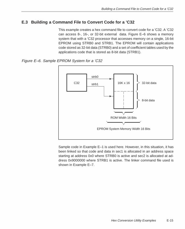
Building a Command File to Convert Code for a ’C32
E-15 Hex Conversion Utility Examples
E.3 Building a Command File to Convert Code for a ’C32
This example creates a hex command file to convert code for a ’C32. A ’C32can access 8-, 16-, or 32-bit external data. Figure E–6 shows a memorysystem that with a ’C32 processor that accesses memory on a single, 16-bitEPROM using STRB0 and STRB1. The EPROM will contain applicationscode stored as 32-bit data (STRB0) and a set of coefficient tables used by theapplications code that is stored as 8-bit data (STRB1).
Figure E–6. Sample EPROM System for a ’C32
16K x 16
8-bit data
32-bit data
EPROM System Memory Width 16 Bits
ROM Width 16 Bits
C32 strb1
strb0
Sample code in Example E–1 is used here. However, in this situation, it hasbeen linked so that code and data in sec1 is allocated in an address spacestarting at address 0x0 where STRB0 is active and sec2 is allocated at ad-dress 0x9000000 where STRB1 is active. The linker command file used isshown in Example E–7.
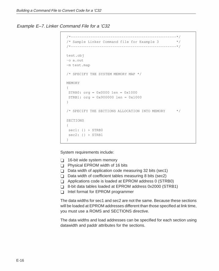
Building a Command File to Convert Code for a ’C32
E-16
Example E–7. Linker Command File for a ’C32
/*––––––––––––––––––––––––––––––––––––––––––––––––*//* Sample Linker Command file for Example 3 *//*––––––––––––––––––––––––––––––––––––––––––––––––*/
test.obj–o a.out–m test.map
/* SPECIFY THE SYSTEM MEMORY MAP */
MEMORY{ STRB0: org = 0x0000 len = 0x1000 STRB1: org = 0x900000 len = 0x1000 }
/* SPECIFY THE SECTIONS ALLOCATION INTO MEMORY */ SECTIONS{ sec1: {} > STRB0 sec2: {} > STRB1}
System requirements include:
� 16-bit wide system memory� Physical EPROM width of 16 bits� Data width of application code measuring 32 bits (sec1)� Data width of coefficient tables measuring 8 bits (sec2)� Applications code is loaded at EPROM address 0 (STRB0)� 8-bit data tables loaded at EPROM address 0x2000 (STRB1)� Intel format for EPROM programmer
The data widths for sec1 and sec2 are not the same. Because these sectionswill be loaded at EPROM addresses different than those specified at link time,you must use a ROMS and SECTIONS directive.
The data widths and load addresses can be specified for each section usingdatawidth and paddr attributes for the sections.
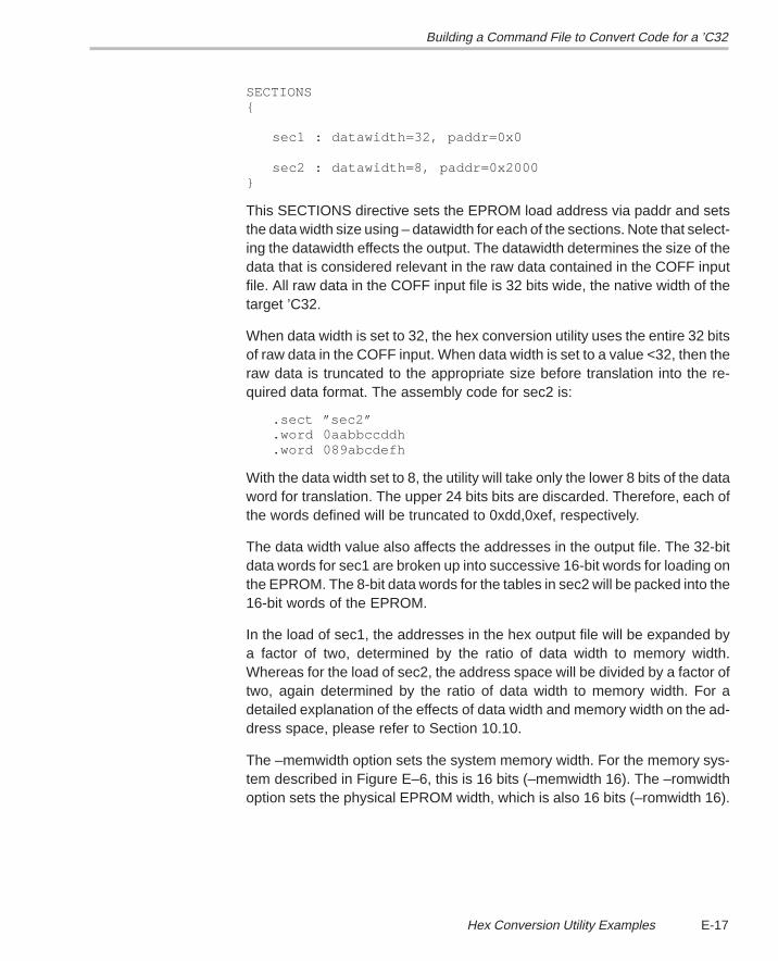
Building a Command File to Convert Code for a ’C32
E-17 Hex Conversion Utility Examples
SECTIONS{
sec1 : datawidth=32, paddr=0x0
sec2 : datawidth=8, paddr=0x2000}
This SECTIONS directive sets the EPROM load address via paddr and setsthe data width size using – datawidth for each of the sections. Note that select-ing the datawidth effects the output. The datawidth determines the size of thedata that is considered relevant in the raw data contained in the COFF inputfile. All raw data in the COFF input file is 32 bits wide, the native width of thetarget ’C32.
When data width is set to 32, the hex conversion utility uses the entire 32 bitsof raw data in the COFF input. When data width is set to a value <32, then theraw data is truncated to the appropriate size before translation into the re-quired data format. The assembly code for sec2 is:
.sect ”sec2”
.word 0aabbccddh
.word 089abcdefh
With the data width set to 8, the utility will take only the lower 8 bits of the dataword for translation. The upper 24 bits bits are discarded. Therefore, each ofthe words defined will be truncated to 0xdd,0xef, respectively.
The data width value also affects the addresses in the output file. The 32-bitdata words for sec1 are broken up into successive 16-bit words for loading onthe EPROM. The 8-bit data words for the tables in sec2 will be packed into the16-bit words of the EPROM.
In the load of sec1, the addresses in the hex output file will be expanded bya factor of two, determined by the ratio of data width to memory width.Whereas for the load of sec2, the address space will be divided by a factor oftwo, again determined by the ratio of data width to memory width. For adetailed explanation of the effects of data width and memory width on the ad-dress space, please refer to Section 10.10.
The –memwidth option sets the system memory width. For the memory sys-tem described in Figure E–6, this is 16 bits (–memwidth 16). The –romwidthoption sets the physical EPROM width, which is also 16 bits (–romwidth 16).
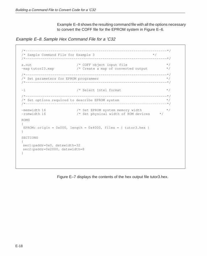
Building a Command File to Convert Code for a ’C32
E-18
Example E–8 shows the resulting command file with all the options necessaryto convert the COFF file for the EPROM system in Figure E–6.
Example E–8. Sample Hex Command File for a ’C32
/*––––––––––––––––––––––––––––––––––––––––––––––––––––––––––––––––––––*//* Sample Command File for Example 3 *//*––––––––––––––––––––––––––––––––––––––––––––––––––––––––––––––––––––*/
a.out /* COFF object input file */–map tutor23.mxp /* Create a map of converted output */
/*––––––––––––––––––––––––––––––––––––––––––––––––––––––––––––––––––––*//* Set parameters for EPROM programmer *//*––––––––––––––––––––––––––––––––––––––––––––––––––––––––––––––––––––*/ –i /* Select Intel format */
/*––––––––––––––––––––––––––––––––––––––––––––––––––––––––––––––––––––*//* Set options required to describe EPROM system *//*––––––––––––––––––––––––––––––––––––––––––––––––––––––––––––––––––––*/
–memwidth 16 /* Set EPROM system memory width */–romwidth 16 /* Set physical width of ROM devices */
ROMS{ EPROM: origin = 0x000, length = 0x4000, files = { tutor3.hex }}
SECTIONS{ sec1:paddr=0x0, datawidth=32 sec2:paddr=0x2000, datawidth=8}
Figure E–7 displays the contents of the hex output file tutor3.hex.
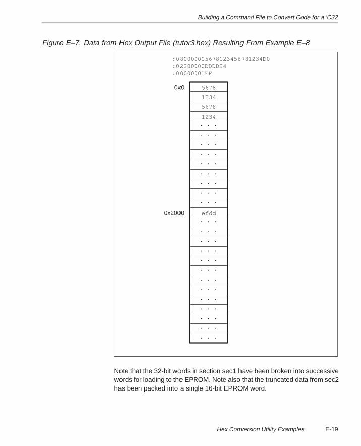
Building a Command File to Convert Code for a ’C32
E-19 Hex Conversion Utility Examples
Figure E–7. Data from Hex Output File (tutor3.hex) Resulting From Example E–8
:00000001FF:02200000DDDD24:080000005678123456781234D0
0x2000
0x0
. . .
. . .
. . .
. . .
. . .
. . .
. . .
. . .
. . .
. . .
. . .
. . .
. . .
. . .
. . .
. . .
. . .
. . .
. . .
. . .
. . .
. . .
efdd
1234
5678
1234
5678
Note that the 32-bit words in section sec1 have been broken into successivewords for loading to the EPROM. Note also that the truncated data from sec2has been packed into a single 16-bit EPROM word.
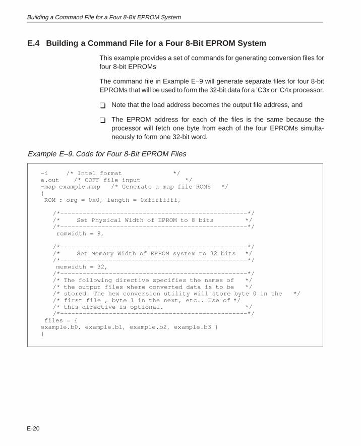
Building a Command File for a Four 8-Bit EPROM System
E-20
E.4 Building a Command File for a Four 8-Bit EPROM System
This example provides a set of commands for generating conversion files forfour 8-bit EPROMs
The command file in Example E–9 will generate separate files for four 8-bitEPROMs that will be used to form the 32-bit data for a ’C3x or ’C4x processor.
� Note that the load address becomes the output file address, and
� The EPROM address for each of the files is the same because theprocessor will fetch one byte from each of the four EPROMs simulta-neously to form one 32-bit word.
Example E–9. Code for Four 8-Bit EPROM Files
–i /* Intel format */a.out /* COFF file input */–map example.mxp /* Generate a map file ROMS */{ ROM : org = 0x0, length = 0xffffffff,
/*––––––––––––––––––––––––––––––––––––––––––––––––––*//* Set Physical Width of EPROM to 8 bits *//*––––––––––––––––––––––––––––––––––––––––––––––––––*/
romwidth = 8,
/*––––––––––––––––––––––––––––––––––––––––––––––––––*//* Set Memory Width of EPROM system to 32 bits *//*––––––––––––––––––––––––––––––––––––––––––––––––––*/
memwidth = 32,/*––––––––––––––––––––––––––––––––––––––––––––––––––*//* The following directive specifies the names of *//* the output files where converted data is to be *//* stored. The hex conversion utility will store byte 0 in the *//* first file , byte 1 in the next, etc.. Use of *//* this directive is optional. *//*––––––––––––––––––––––––––––––––––––––––––––––––––*/
files = { example.b0, example.b1, example.b2, example.b3 }}
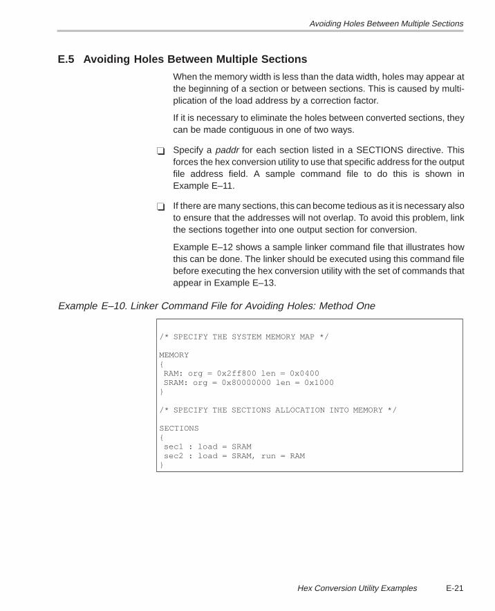
Avoiding Holes Between Multiple Sections
E-21 Hex Conversion Utility Examples
E.5 Avoiding Holes Between Multiple Sections
When the memory width is less than the data width, holes may appear atthe beginning of a section or between sections. This is caused by multi-plication of the load address by a correction factor.
If it is necessary to eliminate the holes between converted sections, theycan be made contiguous in one of two ways.
� Specify a paddr for each section listed in a SECTIONS directive. Thisforces the hex conversion utility to use that specific address for the outputfile address field. A sample command file to do this is shown inExample E–11.
� If there are many sections, this can become tedious as it is necessary alsoto ensure that the addresses will not overlap. To avoid this problem, linkthe sections together into one output section for conversion.
Example E–12 shows a sample linker command file that illustrates howthis can be done. The linker should be executed using this command filebefore executing the hex conversion utility with the set of commands thatappear in Example E–13.
Example E–10. Linker Command File for Avoiding Holes: Method One
/* SPECIFY THE SYSTEM MEMORY MAP */
MEMORY{ RAM: org = 0x2ff800 len = 0x0400 SRAM: org = 0x80000000 len = 0x1000}
/* SPECIFY THE SECTIONS ALLOCATION INTO MEMORY */
SECTIONS{ sec1 : load = SRAM sec2 : load = SRAM, run = RAM}
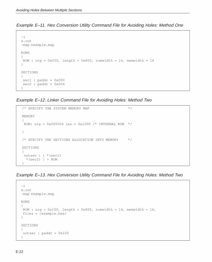
Avoiding Holes Between Multiple Sections
E-22
Example E–11. Hex Conversion Utility Command File for Avoiding Holes: Method One
–i a.out–map example.mxp
ROMS{ ROM : org = 0x000, length = 0x800, romwidth = 16, memwidth = 16}
SECTIONS{ sec1 : paddr = 0x000 sec2 : paddr = 0x004}
Example E–12. Linker Command File for Avoiding Holes: Method Two
/* SPECIFY THE SYSTEM MEMORY MAP */
MEMORY{ ROM: org = 0x000004 len = 0x1000 /* INTERNAL ROM */
}
/* SPECIFY THE SECTIONS ALLOCATION INTO MEMORY */
SECTIONS{ outsec : { *(sec1) *(sec2) } > ROM}
Example E–13. Hex Conversion Utility Command File for Avoiding Holes: Method Two
–i a.out–map example.mxp
ROMS{ ROM : org = 0x100, length = 0x800, romwidth = 16, memwidth = 16, files = {example.hex}}
SECTIONS{ outsec : paddr = 0x100}
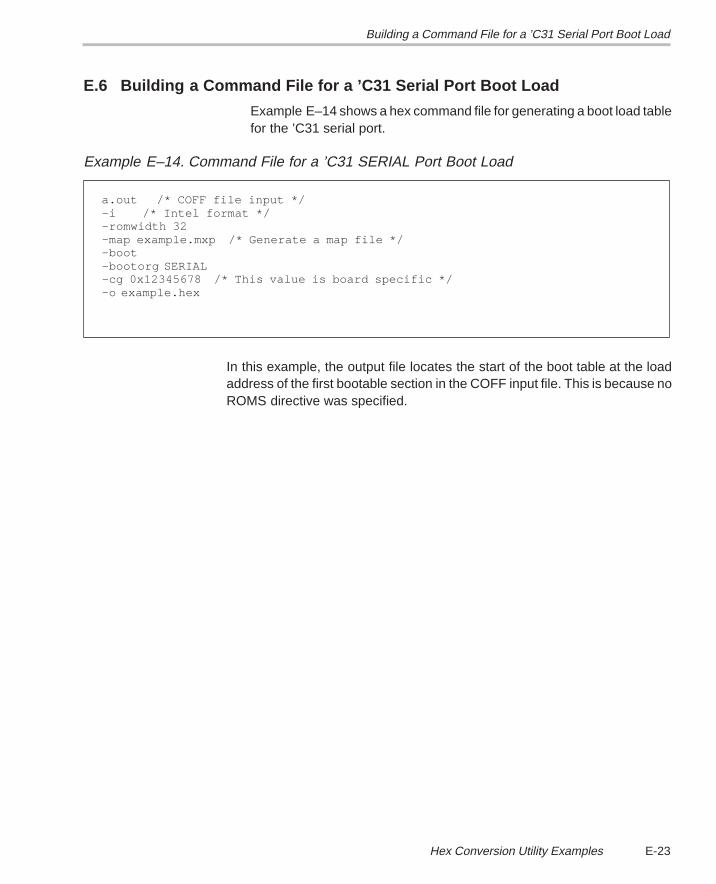
Building a Command File for a ’C31 Serial Port Boot Load
E-23 Hex Conversion Utility Examples
E.6 Building a Command File for a ’C31 Serial Port Boot Load
Example E–14 shows a hex command file for generating a boot load tablefor the ’C31 serial port.
Example E–14. Command File for a ’C31 SERIAL Port Boot Load
a.out /* COFF file input */–i /* Intel format */–romwidth 32 –map example.mxp /* Generate a map file */–boot–bootorg SERIAL–cg 0x12345678 /* This value is board specific */–o example.hex
In this example, the output file locates the start of the boot table at the loadaddress of the first bootable section in the COFF input file. This is because noROMS directive was specified.
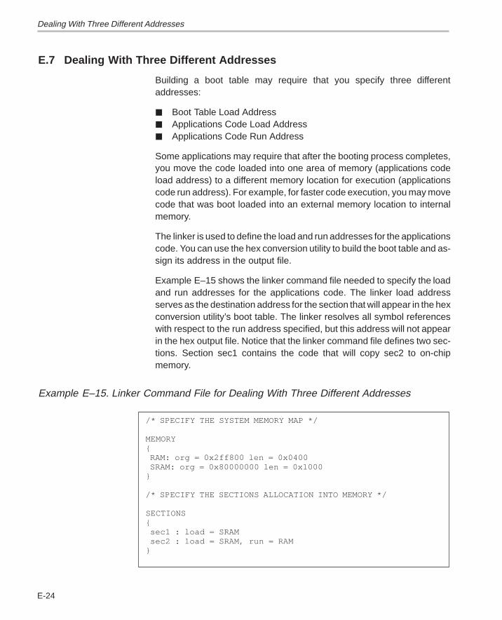
Dealing With Three Different Addresses
E-24
E.7 Dealing With Three Different Addresses
Building a boot table may require that you specify three differentaddresses:
� Boot Table Load Address� Applications Code Load Address� Applications Code Run Address
Some applications may require that after the booting process completes,you move the code loaded into one area of memory (applications codeload address) to a different memory location for execution (applicationscode run address). For example, for faster code execution, you may movecode that was boot loaded into an external memory location to internalmemory.
The linker is used to define the load and run addresses for the applicationscode. You can use the hex conversion utility to build the boot table and as-sign its address in the output file.
Example E–15 shows the linker command file needed to specify the loadand run addresses for the applications code. The linker load addressserves as the destination address for the section that will appear in the hexconversion utility’s boot table. The linker resolves all symbol referenceswith respect to the run address specified, but this address will not appearin the hex output file. Notice that the linker command file defines two sec-tions. Section sec1 contains the code that will copy sec2 to on-chipmemory.
Example E–15. Linker Command File for Dealing With Three Different Addresses
/* SPECIFY THE SYSTEM MEMORY MAP */
MEMORY{ RAM: org = 0x2ff800 len = 0x0400 SRAM: org = 0x80000000 len = 0x1000}
/* SPECIFY THE SECTIONS ALLOCATION INTO MEMORY */
SECTIONS{ sec1 : load = SRAM sec2 : load = SRAM, run = RAM}
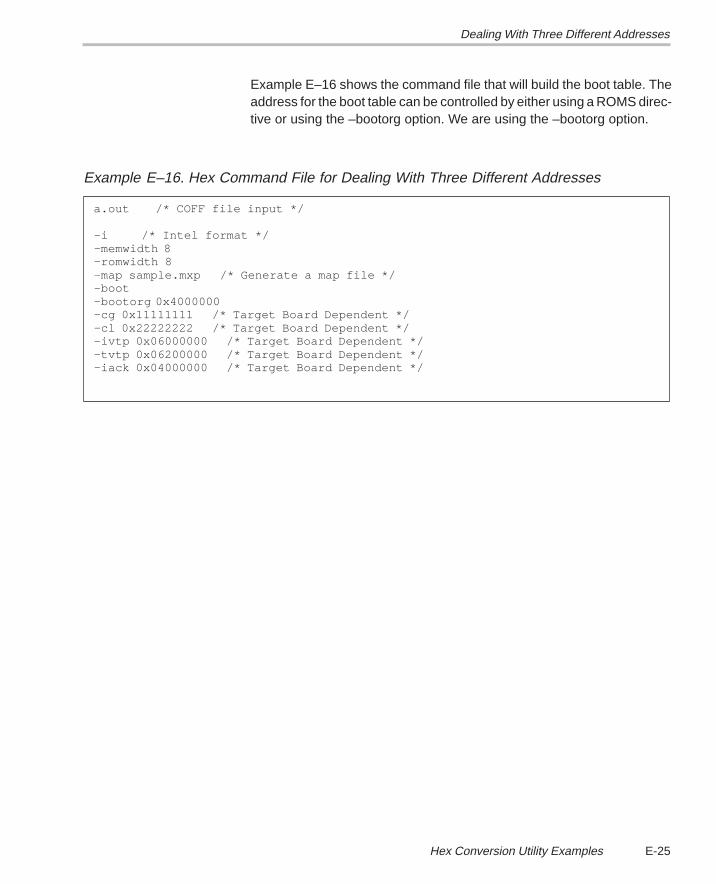
Dealing With Three Different Addresses
E-25 Hex Conversion Utility Examples
Example E–16 shows the command file that will build the boot table. Theaddress for the boot table can be controlled by either using a ROMS direc-tive or using the –bootorg option. We are using the –bootorg option.
Example E–16. Hex Command File for Dealing With Three Different Addresses
a.out /* COFF file input */
–i /* Intel format */–memwidth 8–romwidth 8 –map sample.mxp /* Generate a map file */–boot–bootorg 0x4000000–cg 0x11111111 /* Target Board Dependent */–cl 0x22222222 /* Target Board Dependent */–ivtp 0x06000000 /* Target Board Dependent */–tvtp 0x06200000 /* Target Board Dependent */–iack 0x04000000 /* Target Board Dependent */
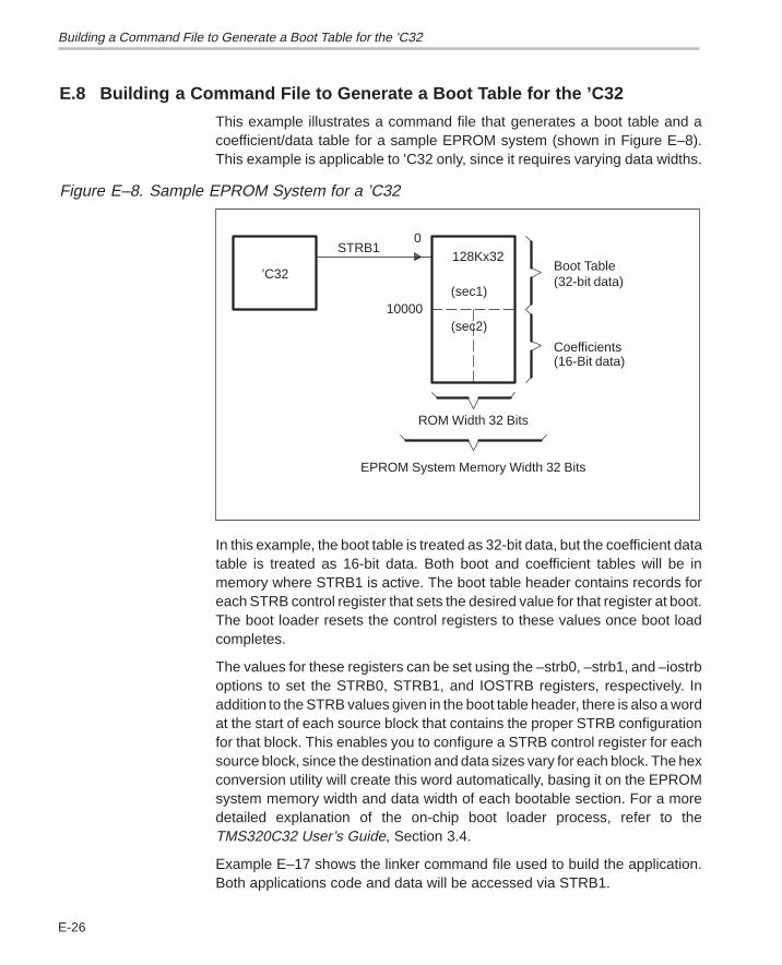
Building a Command File to Generate a Boot Table for the ’C32
E-26
E.8 Building a Command File to Generate a Boot Table for the ’C32
This example illustrates a command file that generates a boot table and acoefficient/data table for a sample EPROM system (shown in Figure E–8).This example is applicable to ’C32 only, since it requires varying data widths.
Figure E–8. Sample EPROM System for a ’C32
Coefficients(16-Bit data)
(32-bit data)Boot Table
EPROM System Memory Width 32 Bits
ROM Width 32 Bits
’C32128Kx32
STRB1
(sec1)
(sec2)10000
0
In this example, the boot table is treated as 32-bit data, but the coefficient datatable is treated as 16-bit data. Both boot and coefficient tables will be inmemory where STRB1 is active. The boot table header contains records foreach STRB control register that sets the desired value for that register at boot.The boot loader resets the control registers to these values once boot loadcompletes.
The values for these registers can be set using the –strb0, –strb1, and –iostrboptions to set the STRB0, STRB1, and IOSTRB registers, respectively. Inaddition to the STRB values given in the boot table header, there is also a wordat the start of each source block that contains the proper STRB configurationfor that block. This enables you to configure a STRB control register for eachsource block, since the destination and data sizes vary for each block. The hexconversion utility will create this word automatically, basing it on the EPROMsystem memory width and data width of each bootable section. For a moredetailed explanation of the on-chip boot loader process, refer to theTMS320C32 User’s Guide, Section 3.4.
Example E–17 shows the linker command file used to build the application.Both applications code and data will be accessed via STRB1.
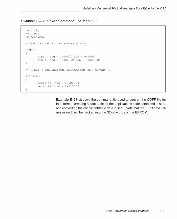
Building a Command File to Generate a Boot Table for the ’C32
E-27 Hex Conversion Utility Examples
Example E–17. Linker Command File for a ’C32
test.obj–o a.out–m test.map
/* SPECIFY THE SYSTEM MEMORY MAP */
MEMORY{
STRB0: org = 0x00000 len = 0x1000STRB1: org = 0x900000 len = 0x200000
}
/* SPECIFY THE SECTIONS ALLOCATION INTO MEMORY */
SECTIONS{
sec1: {} load = 0x900000sec2: {} load = 0x910000
}
Example E–18 displays the command file used to convert the COFF file forIntel format, creating a boot table for the applications code contained in sec1and converting the coefficient/table data in sec2. Note that the 16-bit data val-ues in sec2 will be packed into the 32-bit words of the EPROM.
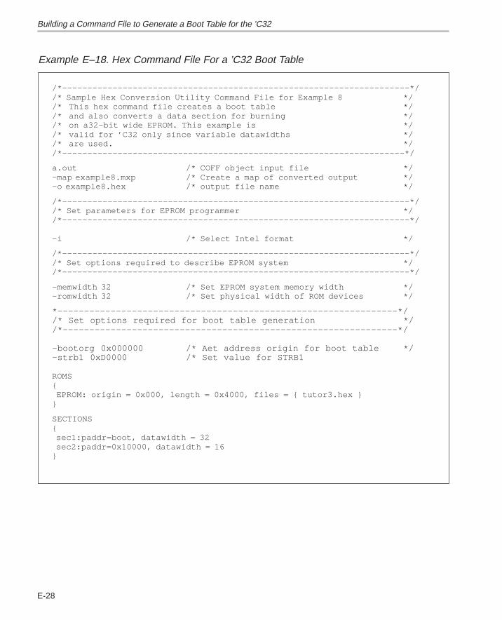
Building a Command File to Generate a Boot Table for the ’C32
E-28
Example E–18. Hex Command File For a ’C32 Boot Table
/*–––––––––––––––––––––––––––––––––––––––––––––––––––––––––––––––––––––*//* Sample Hex Conversion Utility Command File for Example 8 *//* This hex command file creates a boot table *//* and also converts a data section for burning *//* on a32-bit wide EPROM. This example is *//* valid for ’C32 only since variable datawidths *//* are used. *//*––––––––––––––––––––––––––––––––––––––––––––––––––––––––––––––––––––*/
a.out /* COFF object input file */–map example8.mxp /* Create a map of converted output */–o example8.hex /* output file name */
/*–––––––––––––––––––––––––––––––––––––––––––––––––––––––––––––––––––––*//* Set parameters for EPROM programmer *//*–––––––––––––––––––––––––––––––––––––––––––––––––––––––––––––––––––––*/ –i /* Select Intel format */
/*–––––––––––––––––––––––––––––––––––––––––––––––––––––––––––––––––––––*//* Set options required to describe EPROM system *//*–––––––––––––––––––––––––––––––––––––––––––––––––––––––––––––––––––––*/
–memwidth 32 /* Set EPROM system memory width */–romwidth 32 /* Set physical width of ROM devices */
*––––––––––––––––––––––––––––––––––––––––––––––––––––––––––––––––*//* Set options required for boot table generation *//*–––––––––––––––––––––––––––––––––––––––––––––––––––––––––––––––*/
–bootorg 0x000000 /* Aet address origin for boot table */–strb1 0xD0000 /* Set value for STRB1
ROMS{ EPROM: origin = 0x000, length = 0x4000, files = { tutor3.hex }}
SECTIONS{ sec1:paddr=boot, datawidth = 32 sec2:paddr=0x10000, datawidth = 16}
Building a Command File to Generate a Boot Table for the ’C32
E-29 Hex Conversion Utility Examples
Note: Values and data sizes
In this example, that the value of STRB1 is set to 0xD0000. This implies amemory size of 32 bits and a data size of 16. This will be the setting forSTRB1 after the boot load is complete. For program fetches to occur correct-ly, the PRGW pin must be set to 1 so that two consecutive 16-bit reads aredone to form a single program word. For more information about the PRGWpin strobe control registers, refer to the TMS320C32 User’s Guide.
Figure E–9 shows the contents of the output file, example8.hex. Note that thehex conversion utility automatically created the correct data word for theSTRB setting for the source block containing sec1.
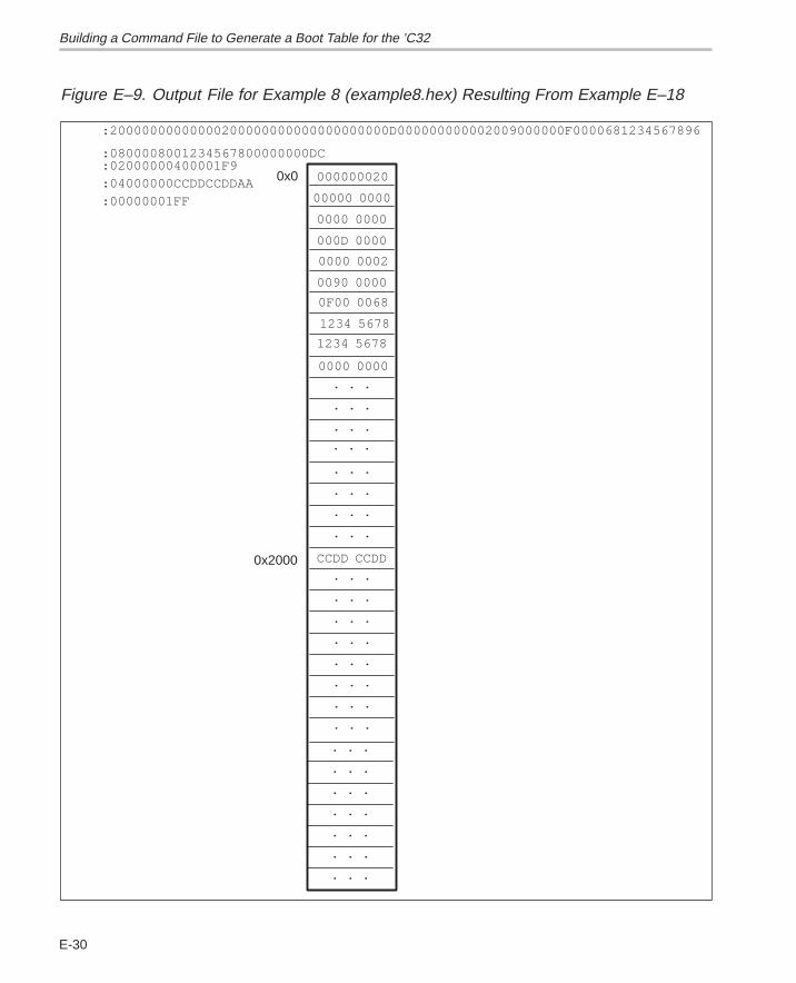
Building a Command File to Generate a Boot Table for the ’C32
E-30
Figure E–9. Output File for Example 8 (example8.hex) Resulting From Example E–18
:02000000400001F9:0800008001234567800000000DC
:20000000000000200000000000000000000D000000000002009000000F0000681234567896
0x2000
0x0
. . .
. . .
. . .
. . .
. . .
. . .
. . .
. . .
. . .
. . .
. . .
. . .
. . .
. . .
. . .
. . .
0000 0000
1234 5678
1234 5678
0F00 0068
0090 0000
0000 0002
CCDD CCDD
000D 0000
0000 0000
00000 0000
000000020:04000000CCDDCCDDAA
. . .
. . .
. . .
. . .
. . .
. . .
. . .
:00000001FF
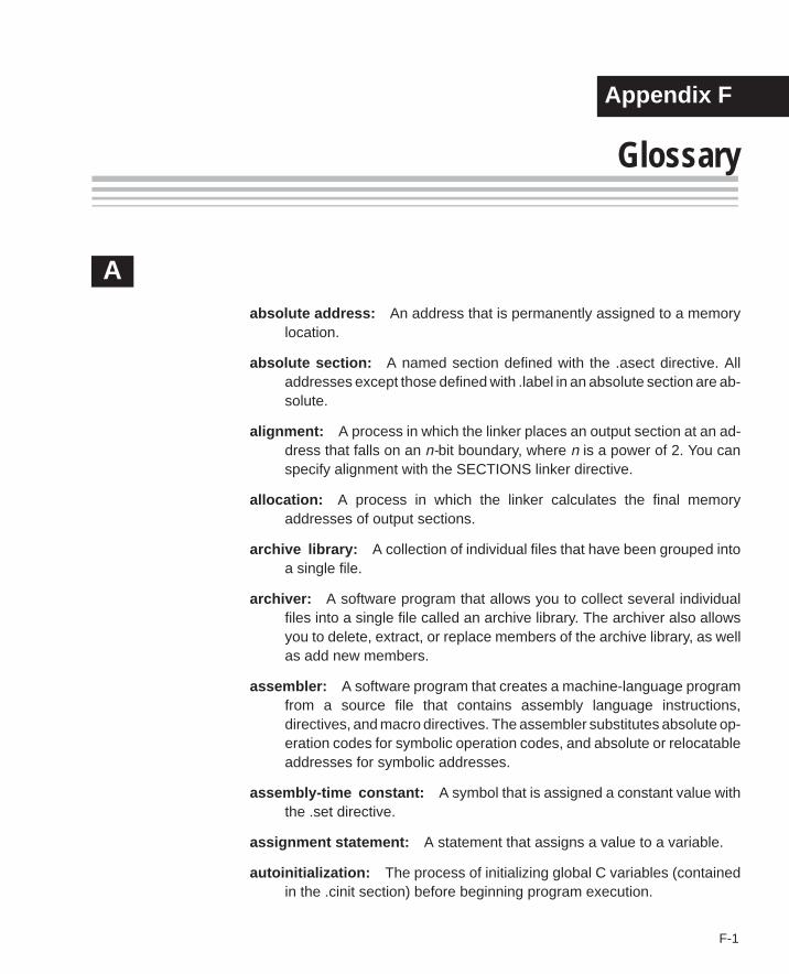
Running Title—Attribute Reference
F-1 Chapter Title—Attribute Reference
Appendix A
Glossary
Aabsolute address: An address that is permanently assigned to a memory
location.
absolute section: A named section defined with the .asect directive. Alladdresses except those defined with .label in an absolute section are ab-solute.
alignment: A process in which the linker places an output section at an ad-dress that falls on an n-bit boundary, where n is a power of 2. You canspecify alignment with the SECTIONS linker directive.
allocation: A process in which the linker calculates the final memoryaddresses of output sections.
archive library: A collection of individual files that have been grouped intoa single file.
archiver: A software program that allows you to collect several individualfiles into a single file called an archive library. The archiver also allowsyou to delete, extract, or replace members of the archive library, as wellas add new members.
assembler: A software program that creates a machine-language programfrom a source file that contains assembly language instructions,directives, and macro directives. The assembler substitutes absolute op-eration codes for symbolic operation codes, and absolute or relocatableaddresses for symbolic addresses.
assembly-time constant: A symbol that is assigned a constant value withthe .set directive.
assignment statement: A statement that assigns a value to a variable.
autoinitialization: The process of initializing global C variables (containedin the .cinit section) before beginning program execution.
Appendix F
Glossary
F-2
auxiliary entry: The extra entry that a symbol may have in the symbol tableand that contains additional information about the symbol (whether thesymbol is a filename, a section name, a function name, etc.).
Bbinding: A process in which you specify an address for an output section or
a symbol.
block: A set of declarations and statements that are grouped together withbraces.
.bss: One of the default COFF sections. You can use the .bss directive toreserve a specified amount of space in the memory map that can laterbe used for storing data. The .bss section is normally uninitialized.
CC compiler: A program that translates C source statements into floating-
point assembly language source statements.
command file: A file that contains linker options and names input files forthe linker.
comment: A source statement (or portion of a source statement) that isused to document or improve readability of a source file. Comments arenot compiled, assembled, or linked; they have no effect on the object file.
common object file format (COFF): A binary object file format thatpromotes modular programming by supporting the concept of sections.
conditional processing: A method of processing one block of source codeor an alternate block of source code, based upon the evaluation of aspecified expression.
configured memory: Memory that the linker has specified for allocation.
constant: A numeric value that can be used as an operand.
cross-reference listing: An output file created by the assembler that liststhe symbols that were defined, what line they were defined on, whichlines referenced them, and their final values.
D.data: One of the default COFF sections. The .data section is an initialized
section that contains initialized data. You can use the .data directive toassemble code into the .data section.
Glossary
F-3 Glossary
directive: Special-purpose commands that control the actions andfunctions of a software tool (as opposed to assembly languageinstructions, which control the actions of a device).
Eemulator: A hardware development system that emulates
TMS320C3x/C4x operation.
entry point: The starting execution point in target memory.
executable module: An object file that has been linked and can beexecuted in a TMS320C3x/C4x system.
expression: A constant, a symbol, or a series of constants and symbolsseparated by arithmetic operators.
external symbol: A kind of symbol that is either 1) defined in the currentmodule and accessed in another, or 2) accessed in the current modulebut defined in another.
Ffield: For the TMS320C3x/C4x, a software-configurable data type whose
length can be programmed to be any value in the range of 1-16 bits.
file header: A portion of a COFF object file that contains general informationabout the object file (such as the number of section headers, the type ofsystem the object file can be downloaded to, the number of symbols inthe symbol table, and the symbol table’s starting address).
Gglobal: A kind of symbol that is either 1) defined in the current module and
accessed in another, or 2) accessed in the current module but definedin another.
GROUP: An option of the SECTIONS directive that forces specified outputsections to be allocated contiguously (as a group).
Hhex conversion utility: A utility that converts COFF object files into one of
several standard ASCII hexadecimal formats, suitable for loading into anEPROM programmer.
Glossary
F-4
high-level language debugging: The ability of a compiler to retain sym-bolic and high-level language information (such as type and functiondefinitions) so that a debugging tool can use this information.
hole: An area between the input sections that compose an output sectionthat contains no actual code or data.
Iincremental linking: Linking files that have already been linked.
initialized section: A COFF section that contains executable code orinitialized data. An initialized section can be built up with the .data, .text,or .sect directive.
input section: A section from an object file that will be linked into anexecutable module.
Llabel: A symbol that begins in column 1 of a source statement and corre-
sponds to the address of that statement.
line number entry: An entry in a COFF output module that maps lines ofassembly code back to the original C source file that created them.
linker: A software tool that combines object files to form an object modulethat can be allocated into system memory and executed by the device.
listing file: An output file created by the assembler that lists source state-ments, their line numbers, and their effects on the SPC.
load address: The address that a section loads at.
loader: A device that loads an executable module into system memory.
Mmacro: A user-defined routine that can be used as an instruction.
macro call: The process of invoking a macro.
macro definition: A block of source statements that define the name andthe code that make up a macro.
macro expansion: The source statements that are substituted for themacro call and are subsequently assembled.
Glossary
F-5 Glossary
macro library: An archive library composed of macros. Each file in thelibrary must contain one macro; its name must be the same as the macroname it defines, and it must have an extension of .asm.
magic number: A COFF file header entry that identifies an object file as amodule that can be executed by the TMS320C3x/C4x.
map file: An output file, created by the linker, that shows the memoryconfiguration, section composition, and section allocation, as well assymbols and the addresses at which they were defined.
member: The elements or variables of a structure, union, archive, or enu-meration.
memory map: A map of target system memory space, which is partitionedinto functional blocks.
mnemonic: An instruction name that the assembler translates into machinecode.
model statement: Instructions or assembler directives in a macro definitionthat are assembled each time a macro is invoked.
Nnamed section: An initialized section that is defined with a .sect directive.
Oobject file: A file that has been assembled or linked and contains machine-
language object code.
object format converter: A program that converts COFF object files intoIntel-format or Tektronix-format object files.
object library: An archive library made up of individual object files.
operand: The arguments, or parameters, of an assembly languageinstruction, assembler directive, or macro directive.
optional header: A portion of a COFF object file that the linker uses toperform relocation at download time.
options: Command parameters that allow you to request additional orspecific functions when you invoke a software tool.
output module: A linked, executable object file that can be downloadedand executed on a target system.
Glossary
F-6
overlay page: A section of physical memory that is mapped into the sameaddress range as another section of memory. A hardware switch deter-mines which range is active.
P
partial linking: The linking of a file that will be linked again.
R
RAM model: An autoinitialization model used by the linker when linking Ccode. The linker uses this model when you invoke the linker with the -croption. The RAM model allows variables to be initialized at load time in-stead of runtime.
raw data: Executable code or initialized data in an output section.
relocation: A process in which the linker adjusts all the references to a sym-bol when the symbol’s address changes.
ROM model: An autoinitialization model used by the linker when linking Ccode. The linker uses this model when you invoke the linker with the -coption. In the ROM model, the linker loads the .cinit section of data tablesinto memory, and variables are initialized at runtime.
run address: The address that a section runs at.
S
section: A relocatable block of code or data that will ultimately occupy con-tiguous space in the TMS320C3x/C4x memory map.
section header: A portion of a COFF object file that contains informationabout a section in the file. Each section has its own header; the headerpoints to the section’s starting address, contains the section’s size, etc.
section program counter: See SPC.
sign-extend: To fill the unused MSBs of a value with the value’s sign bit.
simulator: A software development system that simulatesTMS320C3x/C4x operation.
source file: A file that contains C code or assembly language code that willbe compiled or assembled to form an object file.
Glossary
F-7 Glossary
SPC: An element of the assembler that keeps track of the current locationwithin a section; each section has its own SPC.
static: A kind of variable whose scope is confined to a function or a program.The values of static variables are not discarded when the function or pro-gram is exited; their previous value is resumed when the function or pro-gram is re-entered.
storage class: Any entry in the symbol table that indicates how a symbolshould be accessed.
string table: A table that stores symbol names that are longer than 8 charac-ters (symbol names of 8 characters or longer cannot be stored in thesymbol table; instead, they are stored in the string table). The name por-tion of the symbol’s entry points to the location of the string in the stringtable.
structure: A collection of one or more variables grouped together under asingle name.
symbol: A string of alphanumeric characters that represents an address ora value.
symbolic debugging: The ability of a software tool to retain symbolic infor-mation so that it can be used by a debugging tool such as a simulator oran emulator.
symbol table: A portion of a COFF object file that contains informationabout the symbols that are defined and used by the file.
Ttag: An optional “type” name that can be assigned to a structure, union, or
enumeration.
target memory: Physical memory in a system into which executable objectcode is loaded.
.text: One of the default COFF sections. The .text section is an initializedsection that contains executable code. You can use the .text directive toassemble code into the .text section.
Uunconfigured memory: Memory that is not defined as part of the
TMS320C3x/C4x memory map and cannot be loaded with code or data.
Glossary
F-8
uninitialized section: A COFF section that reserves space in theTMS320C3x/C4x memory map but that has no actual contents. Thesesections are built up with the .bss and .usect directives.
union: A variable that may hold (at different times) objects of different typesand sizes.
UNION: Allocating multiple sections to run at the same address.
unsigned: A kind of value that is treated as a positive number, regardlessof its actual sign.
W
well-defined expression: An expression that contains only symbols or as-sembly-time constants that have been defined before they appear in theexpression.
word: A 16-bit addressable location in target memory.
Index
Index-1
Index
A–a archiver command 7-3
–a assembler option 3-4
–a hex conversion utility option 10-4, 10-44
–a linker option 8-7 to 8-8
A_DIR assembler environment variable 3-7, 3-8,8-13
absolute listercreating the absolute listing file 9-2described 1-3development flow 9-2example 9-5 to 9-10invoking 9-3options 9-3
absolute listingproducing 9-2
absolute output module 8-7
absolute symbols 3-23
addressing modes 5-2 to 5-42
.align assembler directive 4-10, 4-18
alignment 4-10, 4-18, 4-32, 8-32
allocation 2-12, 4-22, 8-29 to 8-32alignment 4-18, 4-32, 8-32binding 8-30blocking 8-32default algorithm 8-47GROUP 8-41named memory 8-31UNION 8-39
alternate directoriesassembler 3-7 to 3-28C_DIR 8-12linker 8-12
ar30 7-3
archive libraries 3-7, 4-52, 7-1 to 7-6, 8-12, 8-15,8-21 to 8-22back referencing 8-17
archiver 1-3, 7-1 to 7-6examples 7-5in the development flow 7-2input 7-1invocation 7-3invoking with command file 7-3options 7-3output 7-1
arithmetic instructions 5-10 to 5-42
arithmetic operators 8-52
array definitions A-26
ASCII-Hex object format 10-44
.asect assembler directive 2-4 to 2-11, 4-6, 4-19,8-36
.asg assembler directive 4-15, 4-20, 6-6listing control 4-11, 4-27
asm30 command 3-4
assembler 1-3character strings 3-15constants 3-12, 3-13, 3-14 to 3-16cross-reference listings 3-27error messages C-1 to C-18expressions 3-20
conditional expressions 3-23legal expressions 3-23 to 3-28operators 3-22overflow/underflow 3-22relocatable symbols 3-23 to 3-28well-defined 3-22
in the development flow 3-3invocation 3-4macros 6-1 to 6-24
Index
Index-2
assembler (continued)output 3-25, 4-11
listingenable 4-48length 4-11page control 4-58page size 4-47suppress 4-48title 4-69width 4-11, 4-47
overview 3-2relocation 2-18 to 2-22runtime relocation 2-20 to 2-22section program counters 2-8sections 2-4 to 2-11sections directives
.asect 2-4
.bss 2-4 to 2-11
.data 2-4
.sect 2-4
.text 2-4
.usect 2-4source listings 3-25source statement format 3-10 to 3-28symbols 2-22, 3-16
assembler directivesassembly-time directives
.asg 4-15
.endstruct 4-15
.eval 4-15
.set 4-15
.struct 4-15
.tag 4-15conditional assembly directives
.break 4-14
.elseif 4-14
.endloop 4-14
.loop 4-14
.else 4-14
.endif 4-14
.if 4-14miscellaneous directives
.emsg 4-16
.end 4-16
.mmsg 4-16
.regalias 4-16
.version 4-16, 4-72
.wmsg 4-16
assembler directives (continued)sections directives
.asect 4-6, 4-19
.bss 4-6
.data 4-6
.label 4-6
.sect 4-6
.text 4-6
.usect 4-6summary table 4-2 to 4-5symbolic debugging directives B-1
.utag/.eos B-8
.block/.endblock B-1, B-2, B-6
.etag/.eos B-1, B-8
.file B-1, B-3
.func/.endfunc B-1, B-4
.line B-1, B-6
.member B-1, B-7
.stag/.eos B-1, B-8
.sym B-1, B-10
.utag/.eos B-1that align the SPC 4-10
.align 4-10
.even 4-10that format the output listing 4-11 to 4-12
.sslist 4-12
.ssnolist 4-12
.list 4-11
.mlist 4-11
.mnolist 4-11
.nolist 4-11
.option 4-11
.page 4-11
.title 4-12that initialize constants 4-7 to 4-9
.hword 4-7
.byte 4-7
.field 4-8
.float 4-7
.hword 4-41
.int 4-7, 4-44
.long 4-7, 4-44
.space 4-9
.string 4-7, 4-64
.word 4-7, 4-44
Index
Index-3
assembler directives (continued)that reference other files 4-13
.copy 4-13
.def 4-13
.global 4-13
.include 4-13
.mlib 4-13
.ref 4-13assembler output 3-25, 4-11assembly language development flow 1-2, 3-3,
7-2, 8-2assembly language instructions
categories 5-8symbols used to define 5-6 to 5-42
assembly-time constants 3-14, 4-61assembly-time directives 4-15assigning a value to a symbol 4-61assigning symbols at link time 8-50 to 8-53assigning the SPC to a symbol 8-50 to 8-51assignment expressions 8-51 to 8-52autoinitialization 8-61
RAM model 8-9, 8-61ROM model 8-9, 8-62
auxiliary entries A-23 to A-28
B–b linker option 8-9big-endian ordering 10-14binary integers 3-12binding 8-30.block assembler directive B-1, B-2block definitions A-17, A-26, A-27, B-2blocking 8-32–boot hex conversion utility option 10-5, 10-29boot loader. See on-chip boot loaderboot table
See also on-chip boot loader, boot tablebuilding using the hex conversion
utility 10-28 to 10-31format 10-28
boot.obj 8-60, 8-63–bootorg hex conversion utility option 10-5, 10-29,
10-31–bootpage hex conversion utility option 10-5,
10-29
.break assembler directive 4-14, 4-50, 6-14listing control 4-11, 4-27
.bss assembler directive 2-4 to 2-11, 4-6, 4-22
.bss section 2-4 to 2-11, 4-6, 8-47, 8-54, A-3holes 8-57initialization 8-57
byte alignment 4-18.byte assembler directive 4-7, 4-23–byte hex conversion utility option 10-4, 10-27
C–c assembler option 3-4C compiler 8-9, 8-60, A-1, B-1
block definitions B-2enumeration definitions B-8file identification B-3function definitions B-4line number entries A-12, B-6line number information A-12linking C code 8-9member definitions B-7model symbols 3-18special symbols A-16storage classes A-19 to A-20structure definitions B-8symbol table entries B-10union definitions B-8
–c linker option 8-9, 8-63C memory pool 8-11, 8-61C system stack 8-15, 8-61C_DIR linker environment variable 8-12, 8-13.C30 3-17.C31 3-17.C32 3-17.C3x 3-17.C40 3-17.C44 3-17.C4x 3-17cache alignment 4-10, 4-18–cg hex conversion utility option 10-5, 10-29,
10-32, 10-35character constants 3-13character strings 3-15.cinit section 8-47, 8-61–cl hex conversion utility option 10-5, 10-29,
10-32, 10-35
Index
Index-4
COFF 2-1 to 2-22, 8-1, A-1 to A-28auxiliary entries A-23 to A-28default sections 2-2file structure A-2 to A-4file types 2-2initialized sections 2-2line number entries A-12 to A-28, B-6line-number table A-12 to A-13named sections 2-2, 2-6optional file header format A-6relocation information A-10 to A-11
relocation type A-11symbol table index A-10virtual address A-10
section headers A-7 to A-9section program counters 2-8sections 2-1 to 2-22special symbols A-16storage classes A-19 to A-20string table A-18subsections 2-8symbol table A-14 to A-28symbolic debugging A-12 to A-28uninitialized sections 2-2
command files (hex conversion utility) 10-6invoking 10-6ROMS directive 10-6SECTIONS directive 10-6
command files (linker) 2-15, 8-4, 8-18 to 8-20example 8-64reserved words 8-20
commentsin a linker command file 8-19in assembly language source code 3-11, 8-19that extend past page width 4-47
common object file format. See COFF
compatibility 3-6
compiler 1-3
condition codesfor the instruction set 5-4 to 5-42
conditional assembly directives 4-14
conditional blocksassembler directives 4-14, 4-42in macros 6-14
conditional expressions 3-23
configured memory 8-23, 8-47
constants 3-12, 3-16assembly-time constants 3-14, 4-61binary integers 3-12character constants 3-13decimal integers 3-12floating-point 3-12, 4-37, 4-46hexadecimal integers 3-13octal integers 3-12
conversion instructions 5-13
.copy assembler directive 3-7, 4-13, 4-24
copy files 3-7, 4-24
COPY section 8-49
–cr linker option 8-9, 8-61, 8-63
creating holes 8-54 to 8-57
cross-reference listings 3-27
D–d archiver command 7-3
–d assembler option 3-4
.data assembler directive 2-4 to 2-11, 4-6, 4-26
data memory 8-23, 8-47
.data section 2-4 to 2-11, 4-6, 4-26, 8-47, A-3
decimal integers 3-12
.def assembler directive 4-13, 4-39
default allocation 2-12, 8-47 to 8-48
default fill value for holes 8-10
default sections 2-2, 4-22, 4-68
defining macros 6-3 to 6-4
directivesSee also assembler directivesassembler
absolute lister 9-8assembly-time symbols
.equ 4-61
.asg 4-20
.eval 4-20
.newblock 4-55
.set 4-61conditional assembly
.break 4-50
.else 4-42
.elseif 4-42
.endif 4-42
.endloop 4-50
.if 4-42
.loop 4-50
Index
Index-5
directives, assembler (continued)miscellaneous
.emsg 4-29
.end 4-31
.label 4-45
.mmsg 4-29
.wmsg 4-29symbolic debugging directives
.sym B-10that align the section program counter (SPC)
.align 4-18
.even 4-32that define sections
.bss 4-22
.data 4-26
.sect 4-60
.text 4-68
.usect 4-70that format the output listing
.drlist 4-11
.drnolist 4-11
.fclist 4-11, 4-33
.fcnolist 4-11, 4-33
.length 4-11, 4-47
.list 4-48
.mlist 4-54
.mnolist 4-54
.nolist 4-48
.option 4-56
.page 4-58
.sslist 4-63
.ssnolist 4-63
.tab 4-67
.title 4-69
.width 4-11, 4-47that initialize constants
.double 4-37
.ieee 4-37
.sfloat 4-37
.byte 4-23
.field 4-34
.float 4-37
.ldouble 4-46
.space 4-62that reference other files
.copy 4-24
.def 4-39
.global 4-39
.include 4-24
.mlib 4-52
.ref 4-39
directives that align the section programcounter 4-10
directives that define sections 4-6
directives that format the output listing 4-11 to 4-12directives that initialize constants 4-7 to 4-9directives that reference other files 4-13.double assembler directive 4-7, 4-37.drlist assembler directive 4-11.drnolist assembler directive 4-11DSECT section 8-49dummy section 8-49
E–e absolute lister option 9-3–e archiver option 7-4–e hex conversion utility option 10-5, 10-29, 10-31–e linker option 8-9.else assembler directive 4-14, 4-42, 6-14.elseif assembler directive 4-14, 4-42, 6-14.emsg assembler directive 4-16, 4-29, 6-17
listing control 4-11, 4-27emulator 1-3.end assembler directive 4-16, 4-31.endblock assembler directive B-1, B-2.endfunc assembler directive B-1, B-4.endif assembler directive 4-14, 4-42, 6-14.endloop assembler directive 4-14, 4-50, 6-14.endm assembler directive 6-3.endstruct assembler directive 4-15entry points
_c_int00 8-9, 8-63for C code 8-63for the linker 8-9_main 8-9
enumeration definitions B-8environment variables
A_DIR 3-7, 3-8C_DIR (linker) 8-12
.eos assembler directive B-1, B-8
.equ assembler directive 4-61error messages
assembler C-1 to C-18linker D-1
.etag assembler directive B-1, B-8
.eval assembler directive 4-15, 4-20, 6-7listing control 4-11, 4-27
evaluation module 1-4.even assembler directive 4-10, 4-32
Index
Index-6
exampleshex conversion utility E-1
expressions 3-20, 8-50conditional 3-23legal 3-23underflow/overflow 3-22well-defined 3-22
Extended Tektronix Hexadecimal objectformat 10-48
external symbols 4-13, 4-39, 4-61
F–f linker option 8-10
.fclist assembler directive 4-11, 4-33, 6-19listing control 4-11, 4-27
.fcnolist assembler directive 4-11, 4-33, 6-19listing control 4-11, 4-27
.field assembler directive 4-8, 4-34
.file assembler directive B-1, B-3
file header A-5 to A-6COFF A-5 to A-6contents A-5flags A-5
file identification B-3
file structure A-2 to A-4
filenamesSee also hex conversion utility, output filenamescopy/include files 3-7extensions
changing defaults 9-3fill
MEMORY specification 8-25
–fill hex conversion utility option 10-4, 10-27
filling holes 8-54 to 8-57
.float assembler directive 4-7, 4-37
floating-point constants 3-13 to 3-28, 4-37, 4-46
.func assembler directive B-1, B-4
function definitions A-17, A-26, A-27, B-4
G–g linker option 8-11
.global assembler directive 2-22, 4-13, 4-39
GROUP (SECTIONS directive) 8-41
H–h linker option 8-10 to 8-11
heap definition 8-11, 8-61
–heap linker option 8-11, 8-61
–heap16 linker option 8-11, 8-61
–heap8 linker option 8-11, 8-61
hex conversion utility 10-1 to 10-49command files 10-6
invoking 10-6ROMS directive 10-6SECTIONS directive 10-6
configuring memory widthsdefining memory word width
(memwidth) 10-4ordering memory words 10-4specifying output width (romwidth) 10-4
description F-3development flow 10-2examples E-1generating a map file 10-4generating a quiet run 10-4hex30 command 10-3image mode
defining the target memory 10-27filling holes 10-4, 10-27invoking 10-4, 10-27numbering bytes sequentially 10-4, 10-27resetting address origin 10-4, 10-27
invoking 10-3 to 10-5in a command file 10-6
memory width (memwidth) 10-9 to 10-11exceptions 10-9
object formatsaddress bits 10-43ASCII-Hex 10-44
selecting 10-4descriptions 10-39 to 10-49Extended Tektronix Hexadecimal 10-48
selecting 10-4Intel MCS-86 Hexadecimal 10-45
selecting 10-4Motorola-S 10-46output width 10-43TI-Tagged 10-47
selecting 10-4on-chip boot loader
See also on-chip boot loaderoptions 10-5, 10-29
Index
Index-7
hex conversion utility (continued)options 10-4 to 10-5
See also on-chip boot loader, options–a 10-4, 10-44–byte 10-4, 10-27–fill 10-4, 10-27–i 10-4, 10-45–image 10-4, 10-27–m 10-46–map 10-4–memwidth 10-4–o 10-4–order 10-4
restrictions 10-15–q 10-4–romwidth 10-4–t 10-4, 10-47–x 10-4, 10-48–zero 10-4, 10-27
ordering memory words 10-14 to 10-15big-endian ordering 10-14little-endian ordering 10-14
output filenames 10-4default filenames 10-24
ROMS directivedefining the target memory 10-27effect 10-19 to 10-20
SECTIONS directive 10-28 to 10-38syntax 10-28
target width 10-8
hex30 command 10-3options 10-3
See also hex conversion utility, options
hexadecimal integers 3-13
holes 8-10, 8-54 to 8-57fill values 8-56in output sections 8-54
.hword assembler directive 4-7, 4-41
I–i assembler option 3-5, 3-7
–i hex conversion utility option 10-4, 10-45
–i linker option 8-13
I MEMORY attribute 8-25
–iack hex conversion utility option 10-5, 10-29,10-32, 10-35
.ieee assembler directive 4-7, 4-37
.if assembler directive 4-14, 4-42, 6-14–image hex conversion utility option 10-4, 10-27image mode. See hex conversion utility, image
mode.include assembler directive 3-7, 4-13, 4-24include files 3-7, 4-24incremental linking 8-58 to 8-59initialized sections 2-2, 2-5 to 2-22, 4-26, 4-60,
4-68, 8-47, 8-54input
archiver 7-1assembler 7-1linker 7-1, 8-2, 8-18
instruction set summaryfunction listing 5-8table 5-20 to 5-42
instructionsarithmetic 5-10 to 5-42conversion 5-13interlocked-operation 5-12load 5-8 to 5-42logic 5-11parallel 5-14program-control 5-11store 5-8 to 5-42three-operand 5-13
.int assembler directive 4-7, 4-44Intel MCS-86 Hexadecimal object format 10-45interlocked-operation instructions 5-12invoking the ...
absolute lister 9-3archiver 7-3 to 7-4assembler 3-4hex conversion utility 10-3 to 10-5linker 8-4 to 8-5
–ivtp hex conversion utility option 10-5, 10-29,10-32
Kkey words linker 8-20
L–l assembler option 3-5–l linker option 8-12.label assembler directive 4-6, 4-45
Index
Index-8
labels 3-10, 3-16local labels (resetting) 4-55using with .byte directive 4-23
.ldouble assembler directive 4-7, 4-46
LDPK Instruction 5-19
legal expressions 3-23 to 3-28
.length assembler directive 4-11, 4-47listing control 4-11, 4-27
length MEMORY specification 8-25
.line assembler directive B-1, B-6
line number entries A-12 to A-28, B-6
line-number table A-12 to A-13
linker 1-3COFF 2-12 to 2-22, 8-1command files 8-4, 8-18
example 8-64command options summary 8-6configured memory 8-23, 8-47development flow 8-2 to 8-3error messages D-1example 8-64expressions 8-50in the development flow 8-2incremental linking 4-60, 8-58input 8-18input from different host machine 8-2invocation 8-4linking C code 8-60 to 8-63lnk30 command 8-4loading a program 2-21map file
example 8-65operators 8-51options summary 8-6output 8-64relocation 2-18 to 2-22runtime relocation 2-20 to 2-22sections 2-12 to 2-22SECTIONS directive 8-27 to 8-34symbols 2-22unconfigured memory 8-23, 8-47
linker command options 8-6 to 8-17
linker input 8-2
linker output 8-2, 8-14
linking C code 8-9, 8-60 to 8-63
.list assembler directive 4-11, 4-48
lister, absolute 9-1 to 9-10
listingcontrol 4-48, 4-56, 4-58page size 4-47
listing control 4-48, 4-54, 4-56, 4-58, 4-69listing file 4-11listing page size 4-47little-endian ordering 10-14lnk30 command 8-4
–a option 8-7 to 8-8–b option 8-9–c option 8-9, 8-60, 8-62, 8-63–cr option 8-9, 8-60, 8-61, 8-63–e option 8-9–l option 8-12–m option 8-14–o option 8-14–r option 8-7 to 8-8–s option 8-14–ar option 8-8–f option 8-10–g option 8-11–h option 8-10options summary 8-6–q option 8-14–u option 8-15–v option 8-16–w option 8-16
load instructions 5-8 to 5-42load linker keyword 2-20, 8-35loading a program 2-21local labels 4-55logic instructions 5-11.long assembler directive 4-7, 4-44.loop assembler directive 4-14, 4-50, 6-14
M–m assembler option 3-5–m hex conversion utility option 10-46–m linker option 8-14.macro assembler directive 6-3macro comments 6-4macro libraries 3-7, 4-52, 7-1macros 6-1 to 6-24
conditional assembly 6-14 to 6-15defining a macro 6-3description 6-2directives summary 6-22 to 6-24
Index
Index-9
macros (continued)formatting the output listing 6-19labels 6-16macro comments 6-4, 6-17macro libraries 4-52, 6-13.mlib assembler directive 3-7, 4-52.mlist assembler directive 4-54nested macros 6-20 to 6-21parameters 6-5 to 6-12producing messages 6-17 to 6-18recursive macros 6-20 to 6-21substitution symbols 6-5 to 6-12
malloc() 8-11, 8-61
malloc16() 8-61
malloc8() 8-61
map file 8-14example 8-65
–map hex conversion utility option 10-4
.member assembler directive B-1, B-7
member definitions B-7
MEMORY linker directive 2-12, 8-23 to 8-26default model 2-12 to 2-22, 8-23, 8-47examples 2-15 to 2-22overlay pages 8-42 to 8-43PAGE option 8-23, 8-47syntax 8-23 to 8-27
memory poolC language 8-11, 8-61
memory width (memwidth) 10-9 to 10-11exceptions 10-9
memory widthsmemory width (memwidth) 10-9 to 10-11
exceptions 10-9ordering memory words 10-14 to 10-15
big-endian ordering 10-14little-endian ordering 10-14
target width 10-8
memory words, ordering 10-14 to 10-15big-endian 10-14little-endian 10-14
.MEMPARM 3-18
–memwidth hex conversion utility option 10-4
messages 4-29
.mexit macro directive 6-3
–mi assembler option 3-5
.mlib assembler directive 3-7, 4-13, 4-52, 6-13use in macros 3-7
.mlist assembler directive 4-11, 4-54, 6-19listing control 4-11, 4-27
.mmsg assembler directive 4-16, 4-29, 6-17listing control 4-11, 4-27
mnemonic field 3-11.mnolist assembler directive 4-11, 4-54, 6-19
listing control 4-11, 4-27Motorola-S object format 10-46–mr assembler option 3-5–mx assembler option 3-5
Nnamed memory 8-31named sections 2-2, 2-6 to 2-7, 4-6, 4-70, 8-47,
8-54, A-3.asect 2-4 to 2-11, 4-6, 4-19.sect 2-4 to 2-11, 4-6, 4-60.usect 2-4 to 2-11, 4-6, 4-70
naming an output module 8-14.newblock assembler directive 4-55.nolist assembler directive 4-11, 4-48NOLOAD section 8-49
O–o hex conversion utility option 10-4–o linker option 8-14object code 3-26object file format. See COFFobject formats
address bits 10-43ASCII-Hex 10-44descriptions 10-39 to 10-49Extended Tektronix Hexadecimal 10-48Intel MCS-86 Hexadecimal 10-45Motorola-S 10-46output width 10-43TI-Tagged 10-47
object libraries 7-1, 8-12, 8-21 to 8-22, 8-60octal integers 3-12on-chip boot loader
boot tablebuilding using the hex conversion util-
ity 10-29format 10-28
booting from communications port 10-31
Index
Index-10
on-chip boot loader (continued)description 10-28options 10-5, 10-29
–boot 10-5, 10-29–bootorg 10-5, 10-29, 10-31–bootpage 10-5, 10-29–cg 10-5, 10-29, 10-32, 10-35–cl 10-5, 10-29, 10-32, 10-35–e 10-5, 10-29, 10-31–iack 10-5, 10-29, 10-32, 10-35–ivtp 10-5, 10-29, 10-32–tvtp 10-5, 10-29, 10-32
setting the entry point 10-31operands 3-11operators 3-22.option assembler directive 4-11, 4-56optional file header format A-6options, absolute lister 9-3–order hex conversion utility option 10-4
restrictions 10-15ordering memory words 10-14 to 10-15
big-endian ordering 10-14little-endian ordering 10-14
origin MEMORY specification 8-25output 8-2
archiver 7-1assembler 4-11linker 8-14, 8-64
output filenames. See hex conversion utility, outputfilenames
output listing 4-11overflow
expression overflow 3-22overlay pages 8-42 to 8-46overlaying sections 8-39 to 8-40
Ppage
control 4-58length 4-47title 4-69width 4-47
.page assembler directive 4-11, 4-58page definition syntax 8-45 to 8-47PAGE option (MEMORY directive) 8-47parallel instructions 5-14
partial linking 8-58 to 8-59
partially linked files 8-58
predefined symbols 3-17
program memory 8-23, 8-47
program-control instructions 5-11
Q–q absolute lister option 9-3
–q archiver option 7-4
–q assembler option 3-5
–q hex conversion utility option 10-4
–q linker option 8-14
R–r archiver command 7-3
–r linker option 8-7 to 8-8, 8-58
R MEMORY attribute 8-25
RAM model of autoinitialization (C compiler) 8-9,8-61
.ref assembler directive 4-13, 4-39
.regalias assembler directive 4-16, 4-59
.REGPARM 3-18
relinking 8-7, 8-8, 8-14affected by –s 8-14
relocatable output module 8-7
relocatable symbols 3-23 to 3-28
relocation 2-18 to 2-22, 3-14, 8-7runtime 2-20
relocation information A-10 to A-11
reserved words 8-20
ROM model of autoinitialization (C compiler) 8-9,8-62
ROMS directive hex conversion utility. See hexconversion utility, ROMS directive
–romwidth hex conversion utility option 10-4
run linker keyword 2-20, 8-35
runtime initialization 8-60
runtime relocation 2-20 to 2-22
runtime support 8-60
Index
Index-11
S–s archiver option 7-4–s assembler option 3-5–s linker option 8-14.sect assembler directive 2-4 to 2-11, 4-6, 4-60section headers A-7 to A-9section program counter 3-25section specifications 8-27sections 2-1 to 2-22
.bss section 4-22converting specified sections 10-28 to 10-38.data section 4-26default sections 2-2, 4-22, 4-26, 4-60directives 4-6
example 2-9 to 2-12initialized sections 2-2, 4-26, 4-60, 4-68named sections 2-2, 2-6, 4-60, 4-68, 4-70section program counters 2-8special section types 8-49subsections 2-8.text section 4-68uninitialized sections 2-2, 4-22, 4-70
SECTIONS directive (hex conversion utility). Seehex conversion utility, SECTIONS directive
sections directives.bss 4-22
SECTIONS linker directive 2-12, 8-27 to 8-34alignment 8-32allocation 8-27, 8-29 to 8-32binding 8-30blocking 8-32default allocation 2-12 to 2-22, 8-47default model 8-25, 8-27examples 2-15 to 2-22GROUP 8-41named memory 8-31overlay pages 8-44 to 8-45section specifications 8-27specifying runtime address 2-20, 8-35specifying two addresses 2-20, 8-35syntax 8-27UNION 8-39
.set assembler directive 4-15, 4-61
.setsect assembler directive 9-8
.setsym assembler directive 9-8
.sfloat assembler directive 4-7, 4-37simulator 1-3
software development tools 1-2
source listings 3-25
source statement field 3-26
source statement format 3-10 to 3-28comment field 3-11label field 3-10mnemonic field 3-11operand field 3-11optional syntaxes 5-3 to 5-42parallel instructions 5-14
source statement number 3-25
.space assembler directive 4-9, 4-62
SPC 2-8, 8-50aligning
to byte boundaries 4-18, 4-32to word boundaries 4-32
assembler symbol 3-11linker symbol 8-50, 8-54
special section types 8-49
special symbols in the symbol table A-16 to A-28
.sslist assembler directive 4-12, 4-63, 6-19listing control 4-11, 4-27
.ssnolist assembler directive 4-12, 4-63, 6-19listing control 4-11, 4-27
stackdefinition (C system) 8-15, 8-61
–stack linker option 8-15, 8-61
.stack section 8-15, 8-61
__STACK_SIZE 8-15, 8-53, 8-61
.stag assembler directive B-1, B-8
static variables A-14
storage classes A-19 to A-20
store instructions 5-8 to 5-42
.string assembler directive 4-7, 4-64
string table A-18
stripping line number entries 8-14
stripping symbolic information 8-14
.struct assembler directive 4-15
structure definitions A-25, B-8
subsectionsoverview 2-8
Index
Index-12
substitution symbolsbuilt-in functions 6-7directives 6-6expansion listing 4-63forcing substitution 6-9in macros 6-5 to 6-12
substitution symbolslocal macro symbols 6-12recursive substitution 6-9subscripted substitution 6-10.var (macro directive) 6-12
support tools 1-2
.sym assembler directive B-1
.sym symbolic debugging directive B-10
symbol tableentry from .sym directive B-10index A-10
symbol names A-18reserved words 8-20
symbol table 2-22, A-14 to A-28
symbol values A-20 to A-21
symbolic constants 3-17
symbolic debugging 8-14, A-12 to A-28, B-1assembler directives B-1block definitions B-2directives
.sym B-10enumeration definitions B-8file identification B-3function definitions B-4line number entries B-6member definitions B-7–s assembler option 3-5structure definitions B-8union definitions B-8
symbols 2-22, 3-16, 6-6assigning values to 4-61at link time 8-50C compiler model
.MEMPARM 3-18
.REGPARM 3-18character strings 3-15predefined 3-17substitution 3-18, 6-5 to 6-12
symbols (continued)version
.C30 3-17
.C31 3-17
.C32 3-17
.C3x 3-17
.C40 3-17
.C44 3-17
.C4x 3-17
.TMS320C30 3-18
.TMS320C31 3-18
.TMS320C32 3-18
.TMS320C40 3-18
.TMS320C44 3-18
.TMS320xx 3-17symbols defined by the linker 8-53 to 8-54.sysm16 section 8-11, 8-61.sysm8 section 8-11, 8-61.sysmem section 8-11, 8-61__SYSMEM_SIZE 8-11, 8-53, 8-61_SYSMEM16_SIZE 8-53_SYSMEM8_SIZE 8-53system stack
C language 8-15, 8-61
T–t archiver command 7-3–t hex conversion utility option 10-4, 10-47.tab assembler directive 4-67.tag assembler directive 4-15target width 10-8Tektronix object format 10-48.text assembler directive 2-4 to 2-11, 4-6, 4-68.text section 2-4 to 2-11, 4-6, 8-47, A-3three-operand instructions 5-13TI-Tagged object format 10-47.title assembler directive 4-12, 4-69TMS320 archiver. See archiver.TMS320C30 3-18.TMS320C31 3-18.TMS320C32 3-18.TMS320C40 3-18.TMS320C44 3-18.TMS320xx 3-17–tvtp hex conversion utility option 10-5, 10-29,
10-32
Index
Index-13
U–u archiver command 7-4–u assembler option 3-5–u linker option 8-15unconfigured memory 8-23, 8-47underflow
expression underflow 3-22uninitialized sections 2-2, 2-4 to 2-5, 4-22, 4-70,
8-47, 8-54holes 8-57initialization 8-57
UNION (SECTIONS directive) 8-39union definitions B-8upward compatibility 3-6.usect assembler directive 2-4 to 2-11, 4-6, 4-70.utag assembler directive B-1, B-8
V–v archiver option 7-4–v assembler option 3-6–v linker option 8-16.var assembler directive
listing control 4-11, 4-27.var macro directive 6-12.version assembler directive 4-16, 4-72
W–w linker option 8-16
W MEMORY attribute 8-25
well-defined expressions 3-22
.width assembler directive 4-11, 4-47listing control 4-11, 4-27
widths. See memory widths
.wmsg assembler directive 4-16, 4-29, 6-17listing control 4-11, 4-27
word alignment 4-32
.word assembler directive 4-7, 4-44
X–x archiver command 7-4
–x assembler option 3-6
–x hex conversion utility option 10-4, 10-48
–x linker option 8-17
X MEMORY attribute 8-25
XDS emulator 1-3
Z–zero hex conversion utility option 10-4, 10-27