Embed Size (px)
Citation preview

TMI-2 Core Bore Examination Resultsa
C. S. Olsen, D. W. Akers, and R. K. McCardellIdaho National Engineering Laboratory
EG&G Idaho Inc.Idaho Falls, Idaho 83415
ABSTRACT
Examinations are being performed on samples obtained from thelower portion of the TMI-2 reactor core as part of the TMI-2 SampleAcquisition and Examination Program. This paper presentspreliminary results of visual examinations, the gamma spectrometryanalyses performed on the intact core bores, and the metallurgicalexaminations. These examinations indicate significant core damageeffects on the distribution of core materials and fission productsin the lower reactor core including the substantial relocation andsegregation of some fission products (e.g., Sb-125 and Ru-106).
INTRODUCTION
Unit 2 of the Three Mile Island pressurized water reactor underwent aloss-of-coolant accident on March 28, 1979, resulting in severe damage to thereactor core. After the accident, four organizations, General PublicUtilities Nuclear Corporation (GPU Nuclear), the Electric Power ResearchInstitute (EPRI), the Nuclear Regulatory Commission (NRC), and the Departmentof Energy (DOE), collectively known as GEND, cosponsored a postaccidentevaluation of the TMI-2 accident. During 1986, a core boring operation wasconducted jointly by EG&G Idaho, Inc. and GPU Nuclear to obtain samples ofthe lower reactor core necessary to spatially characterize the chemical andphysical state of this part of the degraded core. . The results of theseexaminations will be used to provide data on fission product release,interaction between core components, hydrogen generation, and core meltprogression.
Previous examinations of the reactor core indicated that the upperreactor core contained a void region almost entirely surrounded by standingperipheral assemblies (Figure 1). Below the void region was a layer of loosedebris resting on a hard crust . However, conditions in the region of thecore below the debris bed (approximately 50 percent of the core volume) werenot known as there were no penetrations through the crust layer.Consequently, to examine this portion of the reactor core, a core boringsystem capable of penetrating the hard crust was developed to provide accessto the lower core region for both examination and defueling purposes. The
a. Work supported by the U.S. Department of Energy, Assistant Secretary forNuclear Energy, Office of Light Water Reactor Safety and Technology, underDOE contract Number DE-ACO7-76-ID01570.
175

grid
void
Crust
moltenmaterial
plenumdebrismolten
structure
-uuUu 7.1248
Figure 1. End state condition of the TMI-2 reactor core.
176
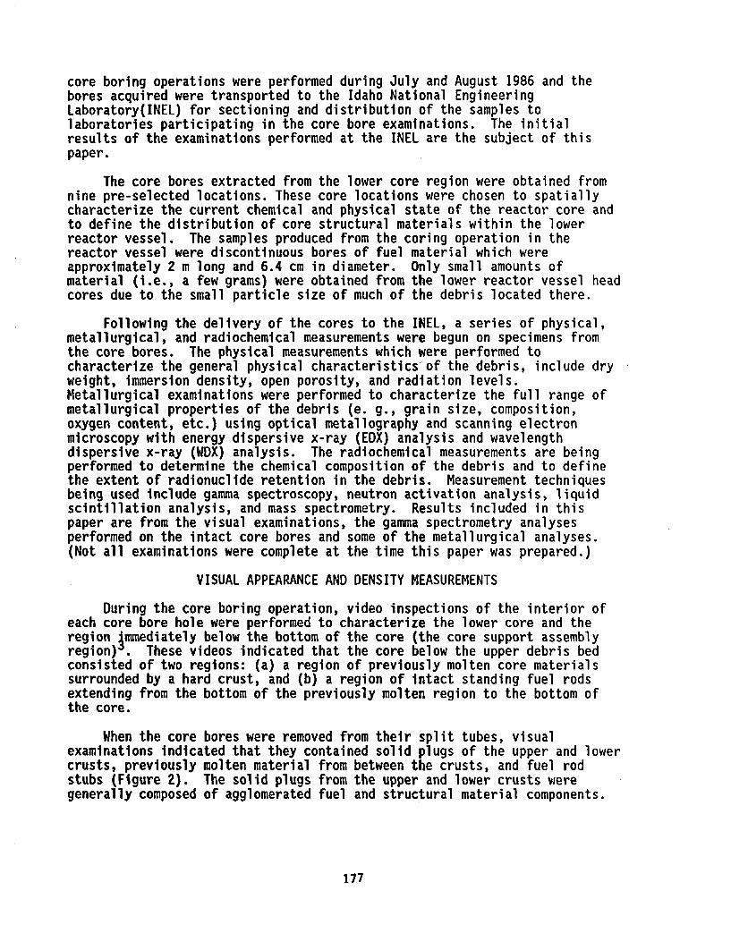
core boring operations were performed during July and August 1986 and thebores acquired were transported to the Idaho National EngineeringLaboratory(INEL) for sectioning and distribution of the samples tolaboratories participating in the core bore examinations. The initialresults of the examinations performed at the INEL are the subject of thispaper.
The core bores extracted from the lower core region were obtained fromnine pre-selected locations. These core locations were chosen to spatiallycharacterize the current chemical and physical state of the reactor core andto define the distribution of core structural materials within the lowerreactor vessel. The samples produced from the coring operation in thereactor vessel were discontinuous bores of fuel material which wereapproximately 2 m long and 6.4 cm in diameter. Only small amounts ofmaterial (i.e., a few grams) were obtained from the lower reactor vessel headcores due to the small particle size of much of the debris located there.
Following the delivery of the cores to the INEL, a series of physical,metallurgical, and radiochemical measurements were begun on specimens fromthe core bores. The physical measurements which were performed tocharacterize the general physical characteristics of the debris, include dryweight, immersion density, open porosity, and radiation levels.Metallurgical examinations were performed to characterize the full range ofmetallurgical properties of the debris (e. g., grain size, composition,oxygen content, etc.) using optical metallography and scanning electronmicroscopy with energy dispersive x-ray (EDX) analysis and wavelengthdispersive x-ray (WDX) analysis. The radiochemical measurements are beingperformed to determine the chemical composition of the debris and to definethe extent of radionuclide retention in the debris. Measurement techniquesbeing used include gamma spectroscopy, neutron activation analysis, liquidscintillation analysis, and mass spectrometry. Results included in thispaper are from the visual examinations, the gamma spectrometry analysesperformed on the intact core bores and some of the metallurgical analyses.(Not all examinations were complete at the time this paper was prepared.)
VISUAL APPEARANCE AND DENSITY MEASUREMENTS
During the core boring operation, video inspections of the interior ofeach core bore hole were performed to characterize the lower core and theregion Ammediately below the bottom of the core (the core support assemblyregion) . These videos indicated that the core below the upper debris bedconsisted of two regions: (a) a region of previously molten core materialssurrounded by a hard crust, and (b) a region of intact standing fuel rodsextending from the bottom of the previously molten region to the bottom ofthe core.
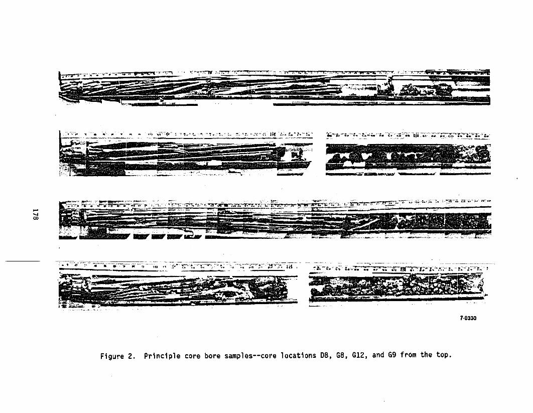
When the core bores were removed from their split tubes, visualexaminations indicated that they contained solid plugs of the upper and lowercrusts, previously molten material from between the crusts, and fuel rodstubs (Figure 2). The solid plugs from the upper and lower crusts weregenerally composed of agglomerated fuel and structural material components.
177
r Sm'~~" ' ; I. "I-s
. .. . . . ,..._ . _..........-
!L6
M-1 it- ____ I PM _ IMMI, -1. � rr"Im-, , ",--,- __ - , 277": MOPM .1
-_ _in'in __ , ,- ,; ~, -,.~ Z7L~ I2
*_ " * --- "' ' . , -7
7-0330
Figure 2. Principle core bore samples--core locations D8, G8, G12, and G9 from the top.
The upper crust samples were composed of a mixture of debris agglomeratedwith substantial amounts of metallic material, while the lower crust sampleswere fuel rods surrounded by previously molten material with a differentcomposition than the upper crust. The solid plugs were 6.4 cm in diameter(the size of the core bore) and ranged from 5 to 11.5 cm in length.
The previously molten region between the crusts appeared to berelatively homogeneous and was easily friable. However, the amount ofmaterial present between the crust layers was less than the amount expectedbased on the video inspections of the core holes. The presumed cause of theless than expected quantities of material was that the friable materialfragmented and about 80% was flushed out during the core boring operation bythe cooling water. The remaining 20% was characterized as "rocks" (largeparticles of debris) of various sizes. There were some 100 rocks larger than2.5 cm in diameter present in the core bores.
The fuel rod stubs located in the lower portion of the core bores rangedfrom 76 cm to 122 cm in length. Shorter stubs were located near the centerof the core and longer ones near the periphery. Initial examinations ofthese rods suggest that the bottom portion of the rods probably remainedcovered with water during the accident.
The initial examinations performed on the core bore samples includedweighing all samples and performing immersion density and open porositymeasurements on the eight large plugs of crust material, and 35 of th 100rock samples. The densities for the 44 samples ranged from 5.44 g/cm3 to9.74 g/cm and the open porosity varied from 5.5 to 19%. The densitiesmeasured age from 6.5% to 48% less than the density of intact fuel material(10.4 g/cm ) which suggests that little intact fuel material material ispresent in the core bore samples. The lower densities are a result ofseveral factors including porosity and the presence of less dense oxidizedzirconium and structural materials. The samples with the lowest density weremostly metallic and quite porous, while the samples with the highest densitywere generally agglomerates of fractured fuel pellets surrounded bypreviously molten materials.
GAMMA SPECTROSCOPY EXAMINATIONOF THE INTACT CORE BORES
This section presents the results of the high resolution gamma rayspectroscopy measurements that were performed on the nine core bores.Initially each core bore was scanned over the entire length to determine thegross gamma ray intensity as a function of position along the axialcenterline of each bore. Following the gross gamma analyses, isotopicmeasurements were performed at intervals of 2.5 cm over the length of eachcore bore and at additional locations of high activity as indicated by thegross gamma radiation surveys.
Examination of the results of the gross and isotopic surveys of the corebores allow several observations to be made concerning fission productbehavior in the lower reactor core:
179
o The gamma spectroscopy data suggest that the upper 2nd lower crustregions contain sigaificg concentur ions (10 -10 greaterthan expected) of Co, cl~Ru, and Sb. Theseradionuclides would be expected to remain as metallic materials andthe metallurgical data indicate that they may have segregated andbeen retained with other metallic components of the core.
o The prior molten material between the crust layers appears to haveymy low concentrations of the more volatile radionuclides such as
'Cs but has retained4lignificMg$ amounts of the refractoryradionuclides (e.g., Ce and Eu).
o The intact fuel rod sections in the lower core appear to haveretained their entire jM entories of fission products including thehigh volatiles (e.g., Cs).
METALLURGICAL EXAMINATION RESULTS
Following the initial nondestructive examinations performed on the corebore samples, samples were selected for metallurgical examinations based onappearance, density, and radionuclide content. Samples were obtained fromthe crust material, the previously molten material from between the crusts,the intact fuel rods, and intact structural components such as control rods,guide tubes, and burnable poison rods. The largest plug samples weresectioned and sampled both transversely and longitudinally to evaluate radialand axial differences in structure and composition. The rock samples weresectioned into either halves or thirds, depending on the size of theparticles, to provide samples of the interiors for both metallurgical andradiochemical examinations. For each sample mounted for optical examination,adjacent samples were obtained for radiochemical analyses to allow comparisonof the metallurgical results with the corresponding radiochemical compositionof the material. The examination results discussed in this paper are fromrepresentative samples of the upper, lower, and peripheral crusts, the mixedceramic and metallic material present in the region between the crusts, andthe fuel rod stubs.
Lower Crust
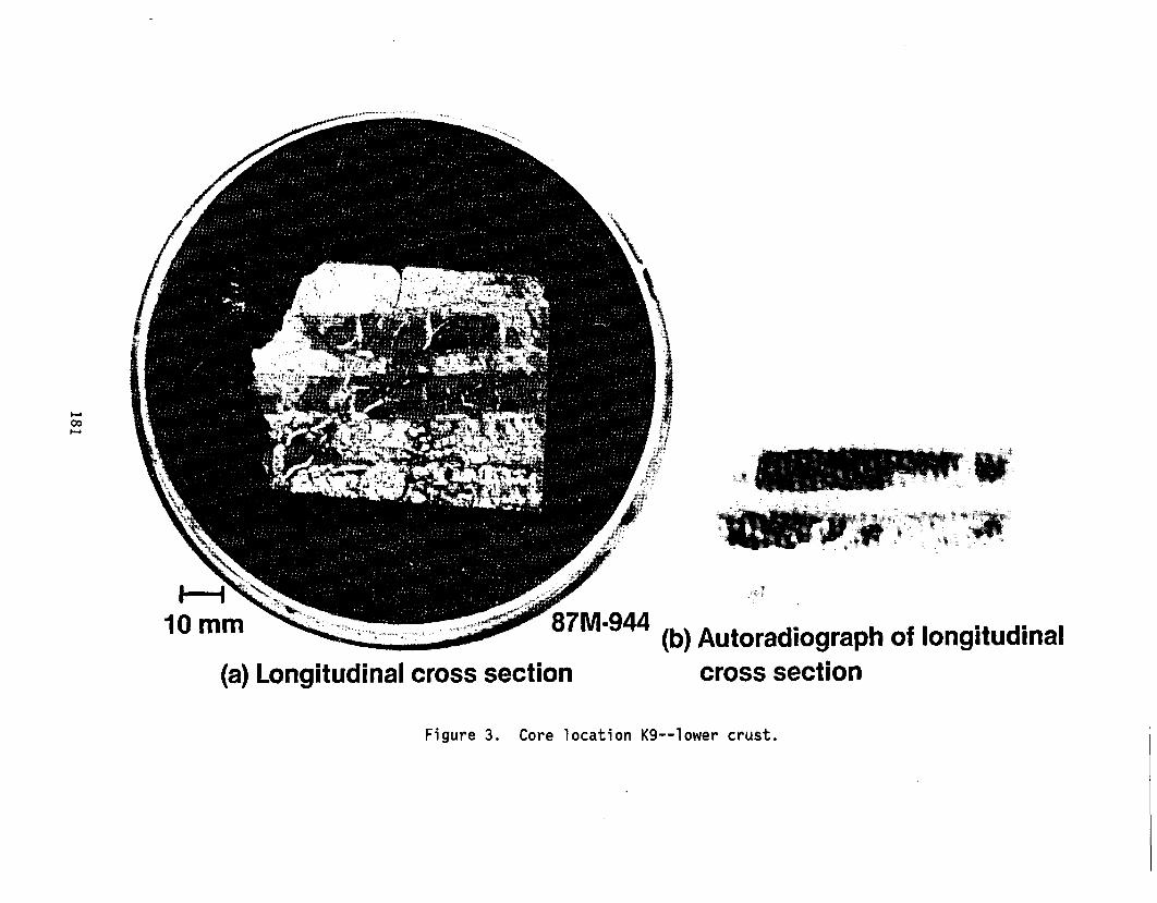
Samples of the lower crust material were obtained at several core borelocations. Figure 3 shows a cross section and the autoradiograph of arepresentative plug of the lower crust taken from near the center of the core(cori location K9). The measured density of this crust sample was 7.2g/cm . The cross section shows the remains of two fuel stack columnssurrounded by previously molten material. Molten material apparently floweddown the coolant channels, dissolved the zircaloy-cladding, and flowed intothe pellet/pellet interfaces and cracks in the pellets.
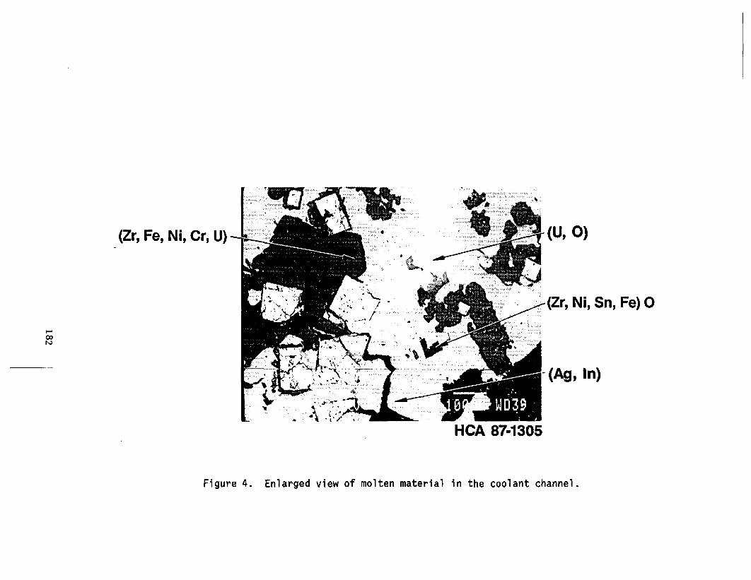
Several areas of this cross section were examined using opticalmetallography and back scattered electron (BSE) image analysis. Figure 4shows an enlarged view of the previously molten material found in the coolant
180
87 94(b) Autoradiograph of longitudinal(a) Longitudinal cross section cross section
Figure 3. Core location K9--lower crust.
(Zr, Fe, Ni, Cr, U) (U. 0)
(Zr, Ni, Sn, Fe) 0
- v- S I*)
-. g In)
co
HCA 87-1305
Figure 4. Enlarged view of molten material in the coolant channel.

channels. This material was composed of a mixture of metallic structural andcontrol rod components with relatively small (100 - 200 micron) UOinclusions. Two metallic phases were present as determined from the BSEanalysis. The principal phase consisted of zirconium, iron, nickel, andchromium and the secondary phase contained an alloy of silver and indium.
Figure 5 shows an enlarged view of the area at a pellet/pellet interfacewhich is typical of the interfaces in this sample. Figure 6 shows the BSEimages for this pellet/pellet interface and the BSE dot maps for U, Zr, andFe. This figure typifies the method used to identify the composition of thevarious phases present in a sample. The BSE image represents a compositeaverage of the atomic number of the elements in a particular phase where thedegree of brightness is proportional to the atomic number of the element(e.g., the high atomic number uranium is brighter than the lower atomicnumber iron) and the individual dot maps represent specific elements wherethe element of interest is brighter than the other elements present in thesample. The uranium and zirconium dot maps in Figure 6 show the presence ofa U0 pellet above a region in the pellet/pellet interface which containsmost y zirconium with small amounts of uranium.
Other metallic phases are also present in the channel as indicated bythe Fe dot map which indicates the interaction of zircaloy with structuraland control materials. Several metallic phases were observed which werecomposed of the following groups of elements (Zr, Sn, Ni, Fe), (Zr, Fe, Cr,Ni, U), (Zr, Ni, In, U), and (Ag, In). Cadmium, a component of the Ag-In-Cdcontrol rods, was found with the Ag and In phases; however, it was present inrelatively small amounts. This is probably due to the relatively highvolatility of this element (B.p. - 940 K). Also, when Zr was alloyed withIn, Fe and Cr were not present. The mechanism resulting in this behavior isnot currently understood.
The metallographic examination of the lower vessel plug samples suggestthat an interaction occurred between the fuel rods and the structuralcomponents (i.e., Fe, Cr, etc.) which resulted in the dissolution of thezircaloy cladding and fuel by the molten structural materials. Thisinteraction would result in a lowering of the melting temperature of thematerial. Based upon the eutectic temperatures of the binary phases ofzirconium with Fe, Ni, or Cr, a minimum possible peak temperature isestimated to be about 1400 K and because there was not an interaction withthe unmelted U02 fragments, a maximum peak temperature of 2200 K issuggested.
In addition to the metallographic examination of the lower crustautoradiography was performed to evaluate the gross distribution of fissionproducts in the crust. This examination indicated that the fission productsin the lower crust were retained within the fuel material and that littleactivity was present in the metallic debris in the coolant channels.
183

, (Ag, In)
(U. O) 7 -(Zr, Ni, In, Sn, U, Ag) O
- (Ag, In)
- (Zr, Fe, Cr, Ni, U)
- (Zr, Fe, Cr, Ni, U) O
- (Zr, Ni, In, U)
(U, Zr, 0)
(Zr, Sn, Ni, Fe) 0 /
HCA 87-1329
Figure 5. Enlarged view of the pellet/pellet interface.

BSE compositional Image
,.r .I, -, < , r ~
Zr dot map HCA 87-1336
I.,'conR
MCA 87-1330 re aot map
Figure 6. Pellet interface--BSE image and dot maps.
Upper Crust Plug
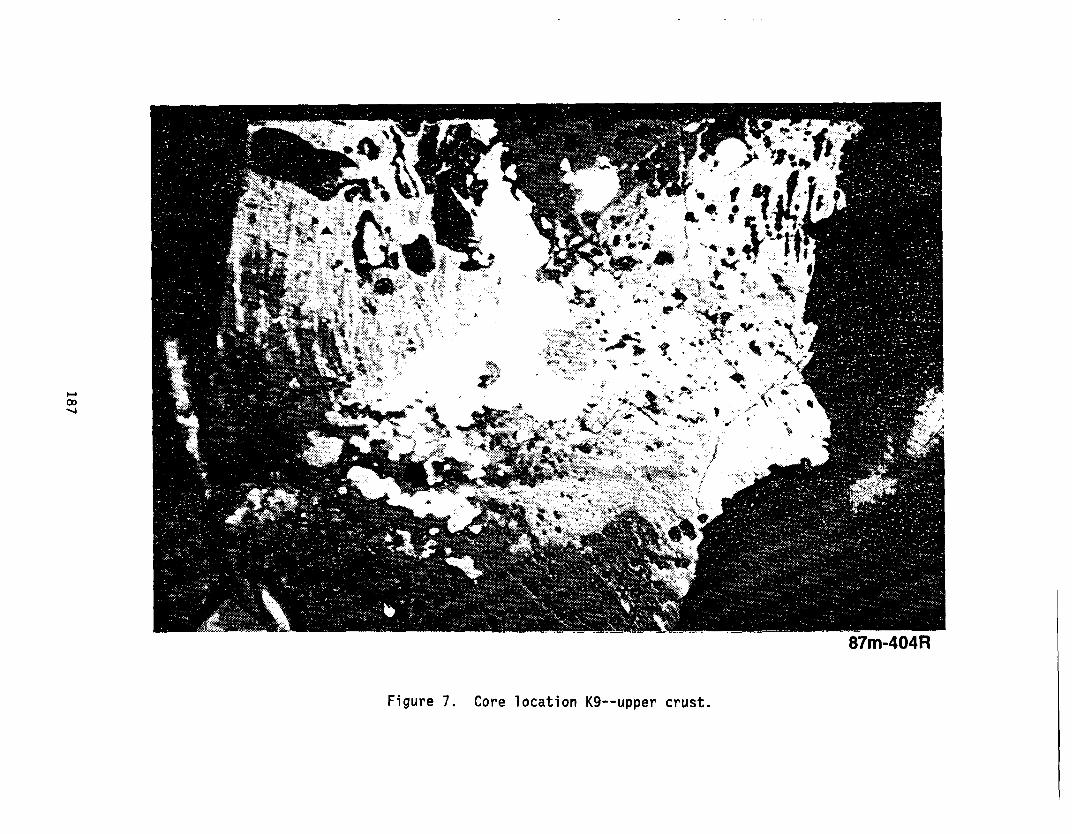
Figure 7 shows a representative cross section of upper crust materialobtained from core bore K9 about 1 meter above the sample discussed in theprevi us section (Figure 3). The bulk density of this plug section was 7.9gm/cm . Two general types of phases were observed in the upper crust, aceramic phase containing mostly fuel material components and a metallic phasecontaining mostly structural components. The composition of the ceramicphase indicated that the interaction between fuel rods and structural/controlrod materials was substantially greater than that observed in the lower crustsamples. No intact fuel material was present and most structural materialswere present as oxides except those which do not oxidize easily (e.g., Ni, Agand In). The BSE images indicate that the ceramic phase was a mixture ofoxides of uranium and zirconium with an average composition of about 56% Uand 21% Zr with small amounts (about 1%) of iron, chromium, and nickel insolid solution. Based upon this composition for the ceramic mixture, thepeak temperature of this layer was estimated to be about 2800 K.
The metallic phase found in the upper crust was principally composed ofiron and nickel; however, as was indicated for the lower crust, a secondmetallic phase was observed which was principally composed of metallic silverand indium. Unlike the lower crust, however, the upper crust did not containmeasurable amounts of Cd, which suggests that the greater degree of materialsinteraction in this crust allowed most of the relatively volatile Cd to bereleased.
In contrast to the fission product behavior observed in the lower crust,the autoradiograph of the sample cross section from the upper crust indicatedhigher concentrations of fission products in the metallic phases rather thanin the ceramic phases. The probable identities of the fission products inthe metallic crust (i.e., Sb-125 and Ru-106) were indicated by the gammaspectroscopy measurements discussed previously. These radionuclides areexpected to be retained as metallic materials in the debris rather than asoxides because of high free energy requirements for oxidation. Otherexaminations indicate that these fission products are associated withmetallic components of the TMI-2 debris . The ceramic phase of the debrisis probably depleted in fission products (e.g., Cs-137) which have relativelyhigh volatilities and were released from the ceramic phases during the hightemperature portion of the accident.
Peripheral Crust
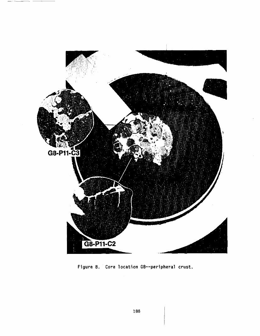
The peripheral crust is that region of the upper crust that is near themid-adius of the core. Densities in this part of the crust range from 8-10g/cm and are generally higher than those observed near the center of thecore. A representative cross section from the peripheral crust (corelocation G8) is shown in Figure 8. Examinations of this cross section andothers from the peripheral crust indicate that the materials behavior in thispart of the core is different than that observed in the upper and lower crustregions. The presence of substantial amounts of metallic structuralcomponents (i.e., Fe, Ni, Ag, and In) is indicated. In Figure 8, the light
186
l -
Figure 7. Core location K9--upper crust.
r
Figure 8. Core location G8--peripheral crust.
188

areas shown in the enlarged section of G8-P11-C3 are a silver-indium alloywhich appears to have flowed into cracks in the ceramic material. Adjacentto this inclusion is a secondary phase containing iron and nickel with asmall amount of chromium. The presence of unmelted fuel in the surroundingmaterial suggests that unmelted fuel from the upper debris bed may haveslumped into the molten metallics.
A second cross section from the peripheral crust at core location G12(Figure 9) shows intact fuel pellet remnants encased in a ceramic matrix ofmixed oxides of uranium and zirconium. This figure shows an apparentinteraction at the fuel pellet/ceramic interface which has resulted in theformation of large (1-4 mm) voids throughout the fuel pellets. This behaviormay have been caused by the collapse of relatively intact fuel pellets fromthe upper debris bed into molten material which then heated the relativelyintact material to high temperatures. The actual cause of the porosity isnot known.
Autoradiographs of the peripheral plug cross sections were taken. Thesedata indicate the presence of significant accumulations of activity in themetallic phases, similar to the behavior observed in the upper crust samples.
Core Interior Particles
Metallographic examinations were performed on 26 "rock-like" particlesfrom the previously molten material region between the crust layers. Therock samples examined were greater than 25 mm in diameter and were selectedbased on density, and surface appearance. Although individual particles wererelatively homogeneous, the metallographic examinations indicated a diversityof structure and composition between particles. The bulk of the samplesexamined were determined to be mixtures of both metallic and ceramic phases,however, examples of entirely ceramic and metallic particles were alsopresent. Examples of each of the material types are discussed in thissection.
A BSE image of an entirely ceramic particle (K9-P3-F) is shown in Figure10. Examination of this particle indicated that this was a relativelyhomogeneous ceramic rock with a number of low atomic number inclusionspresent. An area at an interface between the light and dark areas wasexamined using dot maps to evaluate the composition of these phases. Thelight phases in the examination area were determined to be mixtures ofuranium and zirconium and the dark (lower atomic number) regions weredetermined to be mixtures of iron, chromium, aluminum, and nickel oxides.The presence of nickel oxide in the sample suggests that this sample wassubjected to very oxidizing conditions as nickel has a very high oxidationpotential and would not be expected to be oxidized by steam oxidation only.Particles of this type resemble rock-like particles of previously moltenmaterial obtained from the lower reactor vessel head which contained oxidesof uranium and zirconium in the Matrix and iron and chromium oxide eutecticmixtures in the grain boundaries
189

7FuelPores-,-
-Pores
I 187M-94110mm
Figure 9. Voids produced in fuel pellets in the peripheral crust.
190

sQ. Examination~ area
I.".
Figure 10. Core location K9--ceramic particle (BSE image).

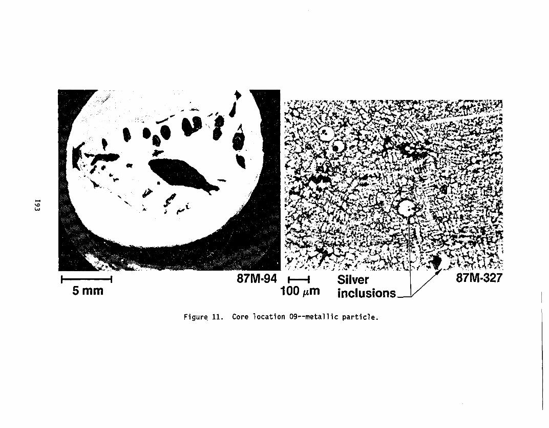
Figure 11 shows an entirely metallic sample which was obtained from fuelassembly location 09 near the periphery of the core. The metallic matrix ofthis sample consisted of a nearly dendritic structure of 59% iron, 25%nickel, and 14% chromium with circular inclusions containing silver, indium,and tin (72% Ag, 15% In, and 9% tin). Although some of these Ag-In-Sninclusions contained voids, many contained a spherical particle of chromiumoxide (Cr203).
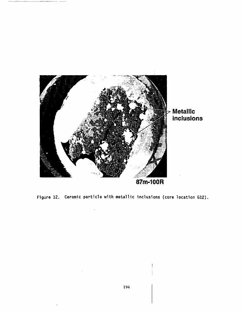
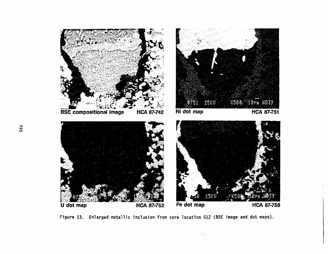
A cross section of a particle (core location G12) which contained aceramic matrix with extensive metallic inclusions is shown in Figure 12. Oneof these inclusions was examined by SEN to evaluate elemental composition.The BSE image and several associated dot maps are shown in Figure 13. Thesedata indicate that a large degree of segregation of individual elements tookplace in this sample. The ceramic matrix of the sample is a mixture of theoxides of uranium and zirconium and, at the periphery of the void containingthe inclusion, is a layer of iron oxide which contains some oxidized nickel.In the metallic inclusion, there is substantial segregation of the elements.At the bottom of the inclusion relatively pure silver is found with littlecontamination from other metallic elements (i.e., indium and cadmium). Abovethis layer, near the particle midpoint, is a nickel-tin layer followed by azone containing nickel with nickel-tin inclusions. Also in the nickelregion, concentrations of the fission product ruthenium were found as ametallic. These data suggest that this fission product, which has a highfree energy requirement for oxidation, is released from the fuel and isretained by metallic structures in the core. The materials behaviorresponsible for the observed structures has not been well defined andadditional information will be required to understand this behavior.
The most common fission product measurable in the metallic inclusions ofthis rock sample was ruthenium; however, technetium, a fission product notfound in nature was also measurable. Also, palladium and tellurium, otherprobable fission products, were measured in association with metallicconstituents (i.e., Ag, In, and Fe). These data suggest that the metallicconstituents of the core retain fission products with varying chemicalcharacteristics and volatilities that have been released from the fuelmaterial.
A beta/gamma autoradiograph of several different particles is shown inFigure 14. Because the radiograph was performed on all samples with only oneexposure time, the intensity of the radiographs may be used as an indicatorof the relative activity among the particles. The ceramic particle (G8-P6-B)has the lowest activity which is about the same as the ceramic phase of themixed ceramic/metallic particle (G8-P1O-A). The metallic particle and thefuel remnant surrounded with metallics also have about the same activity asthe metallic phase in G8-PIO-A. These data again indicate significantrelease or depletion of the activity in the ceramic phases and suggestsimilar retentions for all ceramic or metallic components.
192
1 4
87M-945 mm 100 1AM
I.-
Figure, 11. Core location 09--metallic particle.
- inclusions
87m-100R
Figure 12. Ceramic particle with metallic inclusions (core location G12).
194
, .* ; .2a} aim- f* , ' d t ::
HCA 87-742
- : -
W 'insU dot map HCA 87-752 Fe dot map HCA 87-750
Figure 13. Enlarged metallic inclusion from core location G12 (BSE image and dot maps).

s.0a%
(b) Autoradiograph of particlecross sections(a) Particle cross sections
Figure 14. Core locations N5, G8, and 07--particle cross sections and autoradiographs.
Fuel rods and guide tubes
Fuel rods, and guide tubes from the lower portion of the reactor corewere examined to evaluate the effects of the accident on the intact rods ortubes. Visual examination of the rods indicated that the rods were generallyintact, however, the metallurgical examination indicated that hydriding ofthe fuel rod and guide tubes had occurred. The hydrides were orientated inthe radial direction, which is typical for the cold-work texture of thecladding. Examinat ons performed on fuel rods at the INEL and at ArgonneNational Laboratory indicate that the cladding temperature reachedtemperatures up to 1100 K.
Although no previously molten debris was present between the intact fueland control rods in the core bores, previously molten material was found inan instrument tube in Assembly G8. The molten material which had apparentlyflowed down into the zircaloy tube and interacted with the interior surfaceof the tube was composed mostly of zirconium with some iron and nickel. Italso contained relatively small quantities of silver, indium and cadmium fromthe control rods.
SUMMARY
A summary of the observations and conclusions that have been made fromthe core bore examinations are listed below. The core bore examinationprogram is not complete and additional information will be provided in thefinal examination report.
o The lower crust was formed by freezing of relocated moltencladding, structural, and control materials into the fuel assemblycoolant channels. Peak temperature of this crust was probablybetween 1400 K and 2200 K.
o The upper crust is a mixture of previously molten ceramics,metallics, and solid fuel pieces with an estimated maximumtemperature of 2800 K.
o The metallic structures in the upper crust are composed primarilyof structural (Fe, Cr, and Ni) and control materials (Ag, In, andCd).
o A range of densities were found in the upper, lower and peripheralcrust samples with the higher densities found in the peripheralcrust probably due the lower porosity and greater proportion ofhigher density metallics (e.g., Ag).
o Fission product ruthenium and antimony were retained in themetallic phases of the upper crust and core rocks (mixed ceramicand metallic particles).
197
o In the previously molten material region, cesium is atsubstantially lower concentrations than would be expected forintact fuel material.
o The radionuclide inventory of the intact fuel rods, including themore volatile radionuclides (e.g., Cs-137) appears to be intact.
o Cadmium was not detected in the upper crust of the central coreregion; however, small quantities of Cd were detected in the lowercrust.
o A zircaloy instrument tube at the G8 core location provided apathway where prior molten fuel flowed down into the tube andinteracted with the zircaloy of the tube.
o Particles of prior molten fuel from the central core region had awide variety of compositions. Most were a mixture of ceramic andmetallic components; however, some were entirely metallic orceramic.
REFERENCES
1. M. L. Russell et al., TMI-2 Accident Evaluation Program SampleAcquisition and Examination Plan for FY 1987 and Beyond,EGG-TMI-7521,February 1987.
2. D. W. Akers et. al., TMI-2 Core Debris Grab Samples--Examination andAnalysis, GEND-075, September 1986.
3. E. L. Tolman et. al., TMI-2 Core Bore Acquisition Summary Report,EGG-TMI-7385, Rev. 1, February 1987.
4. C. S. Olsen et. al., Examination of Debris from the Lower Reactor Headof the TMI-2 Reactor (Draft), EGG-TMI-7573, April 1987.
5. L. A. Neimark et. al., Examination of TMI-2 Core Bore Samples, 15thWater Reactor Safety Research Meeting, October 26-30, 1987 (to bepublished).
198


![2008 Prospectus- TMI[1]](https://img.pdfslide.us/doc/110x75/55273073550346d7358b4716/2008-prospectus-tmi1.jpg)