Embed Size (px)
Citation preview

Owner’s ManualModelsTMGM24, TMGM36, TMGM48TMGT24, TMGT36, TMGT48
This manual includes material related to installation,use , cleaning, and care. Exploded view[s], as well as any available parts list[s] and wiring diagram[s] pertaining to the unit[s] covered by this manual are also included.
This manual must be read and understood by all persons using or installing this appliance. Contact your Star dealer if you have any questions concerning installation, use, or maintenance of this equipment.
DO NOT DISCARD THIS MANUAL.
Gas Griddle
2M-Z12966 • Rev. C • 06.2016
TMGT36

LIMITED EQUIPMENT WARRANTYAll workmanship and material in Toastmaster products have a one (1) year limited warranty on parts and labor in the United States and Canada.
Such warranty is limited to the original purchaser only and shall be eff ective from the date the equipment is placed in service. Toastmaster’s
obligation under this warranty is limited to the repair of defects without charge, by the factory authorized service agency or one of its sub-
agencies. Toastmaster will not assume any responsibility for loss of revenue. Models that are considered “portable” (see below) should be
taken to the closest Toastmaster service agency, transportation prepaid. On all shipments outside the U.S.A. and Canada, see the International
Warranty.
This warranty does not apply to any item that is disassembled or tampered with for any purpose other than repair by an authorized service
center or the service center’s sub-agency. This warranty does not apply if damage occurs from improper installation, misuse, wrong voltage,
wrong gas or operated contrary to the Installation and operating instructions. This warranty does not apply to “Special Products” but to regular
catalog items only. Toastmaster’s warranty on “Special Products” is six (6) months on parts and ninety (90) days on labor.
PARTS WARRANTYParts that are sold to repair out of warranty equipment are warranted for ninety (90) days. The labor to replace the part is NOT warrantied.
SERVICES AND EXPENSES NOT COVERED BY WARRANTY• Travel time and mileage rendered beyond the 50-mile radius limit
• Mileage and travel time on “portable” equipment (see below)
• Labor to replace such items that can be replaced easily during
a daily cleaning routine (e.g., removable kettles on fryers, knobs,
grease drawers on griddles, etc.)
• Installation of equipment
• Cleaning of equipment
• Seasoning of griddle plates
PORTABLE EQUIPMENTStar will not honor service bills that include travel time and mileage charges for servicing any products considered “portable” including items
listed below. These products should be taken to the Service Agency for repair:
• Specialty Food Warmers
• Sandwich Grills
• Pop-Up Toasters
• Accessories of any kind (e.g. Sneeze Guards, Manual Pumps, etc.)
• Heat Lamps
The foregoing warranty is in lieu of any and all other warranties expressed or implied and constitutes the entire warranty.
Should you require any assistance regarding the operation or
maintenance of any Toastmaster equipment; write, phone, fax
or email our Service Department. In all correspondence mention
the model number and the serial number of your unit, as well as
the voltage or type of gas you are using.
• Voltage conversions or gas conversions
• Pilot light adjustment
• Miscellaneous adjustments
• Thermostat calibration and bypass adjustment
• Resetting of circuit breakers, safety controls, or reset buttons
• Replacement of bulbs or fuses
• Repair of damage created during transit, delivery, or installation
or created by an act of God.
Business hours: 8:00 a.m. to 4:30 p.m. Central Standard Time
Telephone: 314-678-6303
Fax: 314-781-2714
Email: [email protected]
Website: www.toastmastercorp.com
i

2M-Z
1296
6 R
ev C
Ow
ner’s
Man
ual f
or T
oast
mas
ter T
MG
M a
nd T
MG
T G
as G
riddl
es
TABLE OF CONTENTS
Warranty iGeneral Information and Installation 1–2 Ventilation and Gas Connection 2-4 Daily Operation 5 Exploded Views 6–7 Parts List 8-11 Specifications 12

iii
NOTES

2M-Z
210
01 R
ev-
Ow
ner's
Man
ual f
or IR
CS4
Impi
ngem
ent/
Rad
iant
Spl
it-B
elt C
onve
yor T
oast
er
1 2M-Z
1296
6 R
ev C
Ow
ner’s
Man
ual f
or T
oast
mas
ter T
MG
M a
nd T
MG
T G
as G
riddl
es
SAFETY SYMBOLSThese symbols are intended to alert the user to the presence of important operating and maintenance instructions in the manual accompanying the appliance.
THOROUGHLY INSPECT YOUR UNIT ON ARRIVALThis unit has been tested for proper operation before leaving our plant to ensure delivery of your unit in perfect condition. However, there are instances in which the unit may be damaged in transit. In the event you discover any type of damage to your product upon receipt, you must immediately contact the transportation company who delivered the item to you and initiate your claim with that company. If this procedure is not followed, it may aff ect the warranty status of the unit. If damage or loss is not apparent until after equipment is unpacked, a request for inspection of concealed damage must be made with carrier within 15 days. Please record the model number, serial number, voltage, and purchase date in the area below at the time of receipt..
Model Number
Serial Number
Voltage
Purchase Date
MAINTENANCE AND REPAIRSContact your local authorized service agent for service or required maintenance. Please have the information in the above fi elds ready when you call to ensure a faster service.
Using any part other than genuine Toasmaster factory supplied parts relieves the manufacturer of all liability. Due to periodic changes in designs, methods, procedures, policies, and regulations, the specifi cations contained in this document are subject to change without notice. Toastmaster reserves the right to change product specifi cations and design without notice. Such revisions do not entitle the buyer to corresponding changes, improvements, additions or replacements for previously purchased equipment. While Toastmaster exercises good faith eff orts to provide information that is accurate, we are not responsible for errors or omissions in information provided or conclusions reached as a result of using the specifi cations. By using the information provided, the user assumes all risks in connection with such use.
PLEASE REFER TO THE WARRANTY PAGE FOR SPECIFIC WARRANTY INFORMATION.
AUTHORIZED SERVICE AGENT LISTINGReference the listing provided with the unit or for an updated listing go to the website or call customer service to fi nd an agent.
Business hours: 8:00 a.m. to 4:30 p.m. Central Standard Time Telephone: 314-678-6303Fax: 314-781-2714Email: [email protected]: www.toastmastercorp.com
Please visit www.starwebconnect.com/manuals.aspx for digital versions of any documents associated with this unit.

2
GENERAL SAFETY INFORMATIONThis equipment is designed and sold for commercial use only, and is intended for use by personnel trained and experienced in its operation. This is not sold for consumer use in and around the home nor for use directly by the general public in food service locations.
Before using your new equipment, read and understand all the instructions and labels associated with the unit prior to putting it into operation. Make sure all people associated with its use understand the units operation and safety before they use the unit.
GENERAL INSTALLATION INFORMATIONThe unit is shipped fully assembled and ready to plug into a standard outlet specified for its voltage and amp draw. If improper electrical supply can be determined through troubleshooting, contact a qualified electrician prior to using the unit. Removal or replacement of the power cord or plug will void the warranty. Should you require assistance, contact your local authorized service agent for any service or required maintenance.
Set the unit so that the rear is 0.25 inches (6 mm) higher than the front using the adjustable feet. Make certain the griddle has at least the minimum clearance on the sides and back as called out on the nameplate of the unit. This unit should be installed on a non-combustible countertop only.
Before using the unit for the first time, ensure to clean the unit properly. Refer to the CleaningProcedure document for cleaning instructions.
VENTILATIONMake certain not to obstruct the flow of combustion and ventilation air. Provisions for adequate air supply must be furnished. The legs supplied with the unit must be installed. Make certain that air intake openings in the bottom of the appliance are not obstructed, as they are essential for proper combustion and operation of the appliance.
It is essential that some form of exhaust hood be provided over the griddle to carry off fumes and gases. The unit should never be directly connected to a flue or stack.
GAS CONNECTIONTHE INSTALLATION OF THE APPLIANCE SHOULD CONFORM TO THE NATIONAL FUEL GAS CODE “ANSI Z223.1 - LATEST EDITION” AND ALL LOCAL GAS COMPANY RULES AND REGULATIONS.
IN CANADA INSTALLATION SHOULD BE IN ACCORDANCE WITH THE CURRENT CAN/ CGA-B149.1 NATURAL GAS INSTALLATION CODE OR CAN/CGA-B149.2 PROPANE INSTALLATION CODE AND LOCAL CODES WHERE APPLICABLE.
Improper installation, adjustment, alteration, service, or maintenance can cause propertydamage, injury, or death. Read the installation, operating and maintenance instructionsthoroughly before installing or servicing the equipment.
For your safety, do not store or flammable or vapor producing liquids [such as gasoline], in the vicinity of this or any other appliance. Keep the operating area clear and free from combustible materials.
For your safety, follow these steps if you smell gas.i. Do not touch electrical switches.ii. Extinguish any open flame.iii. Immediately call your gas company.

2M-Z
210
01 R
ev-
Ow
ner's
Man
ual f
or IR
CS4
Impi
ngem
ent/
Rad
iant
Spl
it-B
elt C
onve
yor T
oast
er
3 2M-Z
1296
6 R
ev C
Ow
ner’s
Man
ual f
or T
oast
mas
ter T
MG
M a
nd T
MG
T G
as G
riddl
es
This appliance and its pressure regulator must be isolated from the gas supply piping system by closing its individual manual shutoff valve during any pressure testing of the gas supply piping system at test pressures equal to or less than 1/2 PSIG (3.45KPA). For the protection of you and your property, we recommend a qualified installing agency install this unit. They should be familiar with gas installations and your local gas company requirements. In any case, your gas company should be called to approve the final installation. Detailed instructions should be posted in a prominent location, to be followed in the event the operator smells gas. Obtain the instructions from the local gas supplier.
GAS PIPINGGas piping will need to be installed correctly and be an appropriate size to provide a supply of gas sufficient to meet the full gas input of the appliance. If the appliance is to be connected to existing piping, it will need to be checked to determine if it has adequate capacity before installation. Joint compound should be used sparingly and only on the male threads of the pipe joints. Any compounds used will need to be resistant to LP and Natural gases.
Any loose dirt or metal particles which are allowed to enter the gas lines on this appliance will damage the valve and affect its operation. When installing this appliance, all pipe and fittings must be free from loose dirt.
GAS PRESSURE REGULATORA convertible pressure regulator is provided with each griddle. It should be connected to the inlet pipe at the rear of the unit. The gas supply line is then connected to it. It is shipped set for 6-inch (15.24 cm) water column manifold pressure for use with natural gas. For LP use, the pressure will need to be adjusted as directed in the steps below.
MANUAL SHUT-OFF VALVEA manual shut-off valve should be installed upstream from the union and within six [6] feet (1.829 m) of this unit.
LP [PROPANE] GAS CONVERSIONThis griddle is equipped with fixed orifice hoods and is shipped from the factory for use on naturalgas. This griddle uses #47 drill orifice hoods for natural gas and #55 drill orifice hoods for LP [propane]. To convert to LP [propane] gas, install the alternate burner orifice hoods located in the grease drawer, using the following procedure.
i. Remove the front panel by removing the screws located on the front and bottom.ii. Remove the burners from the orifice hoods. This is accomplished by removing the burner mounting screws and sliding the burners off the hoods.iii. Remove the natural gas orifice hoods and install the propane hoods the were provided.iv. Reinstall the burners.v. Reinstall the front panel.
vi. Remove the slotted, or hex-headed, plug from the pressure regulator. Invert the plug and reinstall. The letters “LP” should now be visible on the plug. The regulator is now set for 10-inch (25.4cm) water column manifold pressure. To check pressure, a 1/8-inch pipe plug on the supply pipe can be removed for attaching a pressure gauge.

4
CONNECTING GAS SUPPLY LINEThe gas inlet of the griddle is sealed at the factory to prevent the entry of dirt and debris. Do not remove this seal until the actual connection is made to the gas supply line.
CHECKING FOR GAS LEAKSSoap and water solution or other material acceptable for the purpose should be used in locating gas leakage. Matches, candle flame, or other sources of ignition should not under any circumstances be used for this purpose. Check the entire piping system for leaks immediately after connection.
LIGHTING INSTRUCTIONSThe griddles are equipped with standing pilots and should be lit immediately after the gas is turned on. Pilot flames can be lit and observed through the front panel view ports, but the best access for lighting the pilot is from the bottom of the unit, behind the center wall. When griddle is first lit, it will smoke until the preservation oils and impurities are burned off. Use the following procedure to light all pilots.
i. Turn off the main valve to the unit and wait 5 minutes to clear gas.ii. Turn off all knobs and pilot valves.iii. Turn on the main valve and light all pilots.iv. Turn the burner knobs to desired setting.v. To turn burners off, turn knobs off.
PILOT LIGHT REGULATIONAdjust pilot light flames as small as possible, while still being high enough to light burner immediately when the burner valve is turned on high.
BURNER ADJUSTMENT [TMGM MODELS]i. Remove the front panel.ii. Turn the burner valve knob to the highest temperature position.
iii. Close the air shutter on the front of the burner to give a soft blue flame with luminous tips and open to a point where the yellow tips disappear and a hard blue flame is obtained. Repeat for all burners.
BURNER ADJUSTMENT (MODELS TMGT)i. Remove the front panel.
ii. Push dial and set the thermostat of one burner to 450°F (232°C).iii. Close the air shutter on the front of the burner to give a soft blue flame with luminous tips and
open to a point where the yellow tips disappear and a hard blue flame is obtained. Repeat for all burners.
2M-Z
210
01 R
ev-
Ow
ner's
Man
ual f
or IR
CS4
Impi
ngem
ent/
Rad
iant
Spl
it-B
elt C
onve
yor T
oast
er
5 2M-Z
1296
6 R
ev C
Ow
ner’s
Man
ual f
or T
oast
mas
ter T
MG
M a
nd T
MG
T G
as G
riddl
es
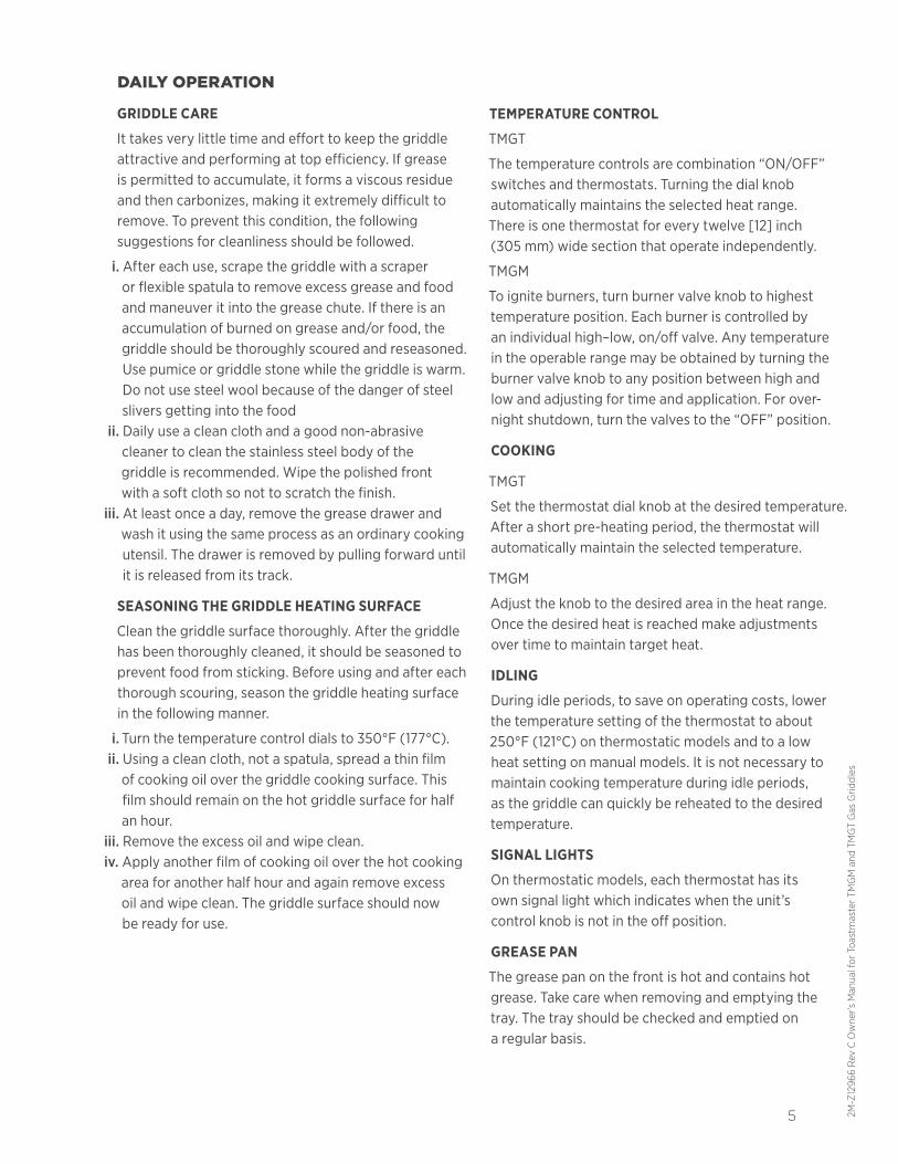
DAILY OPERATION
GRIDDLE CARE
It takes very little time and effort to keep the griddle attractive and performing at top efficiency. If grease is permitted to accumulate, it forms a viscous residue and then carbonizes, making it extremely difficult to remove. To prevent this condition, the following suggestions for cleanliness should be followed.
i. After each use, scrape the griddle with a scraper or flexible spatula to remove excess grease and food and maneuver it into the grease chute. If there is an accumulation of burned on grease and/or food, the griddle should be thoroughly scoured and reseasoned. Use pumice or griddle stone while the griddle is warm. Do not use steel wool because of the danger of steel slivers getting into the food
ii. Daily use a clean cloth and a good non-abrasive cleaner to clean the stainless steel body of the griddle is recommended. Wipe the polished front with a soft cloth so not to scratch the finish.
iii. At least once a day, remove the grease drawer and wash it using the same process as an ordinary cooking utensil. The drawer is removed by pulling forward until it is released from its track.
SEASONING THE GRIDDLE HEATING SURFACE
Clean the griddle surface thoroughly. After the griddle has been thoroughly cleaned, it should be seasoned to prevent food from sticking. Before using and after each thorough scouring, season the griddle heating surface in the following manner.
i. Turn the temperature control dials to 350°F (177°C).ii. Using a clean cloth, not a spatula, spread a thin film of cooking oil over the griddle cooking surface. This film should remain on the hot griddle surface for half an hour.
iii. Remove the excess oil and wipe clean.iv. Apply another film of cooking oil over the hot cooking area for another half hour and again remove excess oil and wipe clean. The griddle surface should now be ready for use.
TEMPERATURE CONTROL
TMGT
The temperature controls are combination “ON/OFF” switches and thermostats. Turning the dial knobautomatically maintains the selected heat range.There is one thermostat for every twelve [12] inch (305 mm) wide section that operate independently.
TMGM
To ignite burners, turn burner valve knob to highest temperature position. Each burner is controlled by an individual high–low, on/off valve. Any temperature in the operable range may be obtained by turning the burner valve knob to any position between high and low and adjusting for time and application. For over- night shutdown, turn the valves to the “OFF” position.
COOKING
TMGT
Set the thermostat dial knob at the desired temperature. After a short pre-heating period, the thermostat will automatically maintain the selected temperature.
TMGM
Adjust the knob to the desired area in the heat range. Once the desired heat is reached make adjustments over time to maintain target heat.
IDLING
During idle periods, to save on operating costs, lower the temperature setting of the thermostat to about 250°F (121°C) on thermostatic models and to a low heat setting on manual models. It is not necessary to maintain cooking temperature during idle periods, as the griddle can quickly be reheated to the desired temperature.
SIGNAL LIGHTS
On thermostatic models, each thermostat has its own signal light which indicates when the unit’s control knob is not in the off position.
GREASE PAN
The grease pan on the front is hot and contains hot grease. Take care when removing and emptying the tray. The tray should be checked and emptied on a regular basis.
6
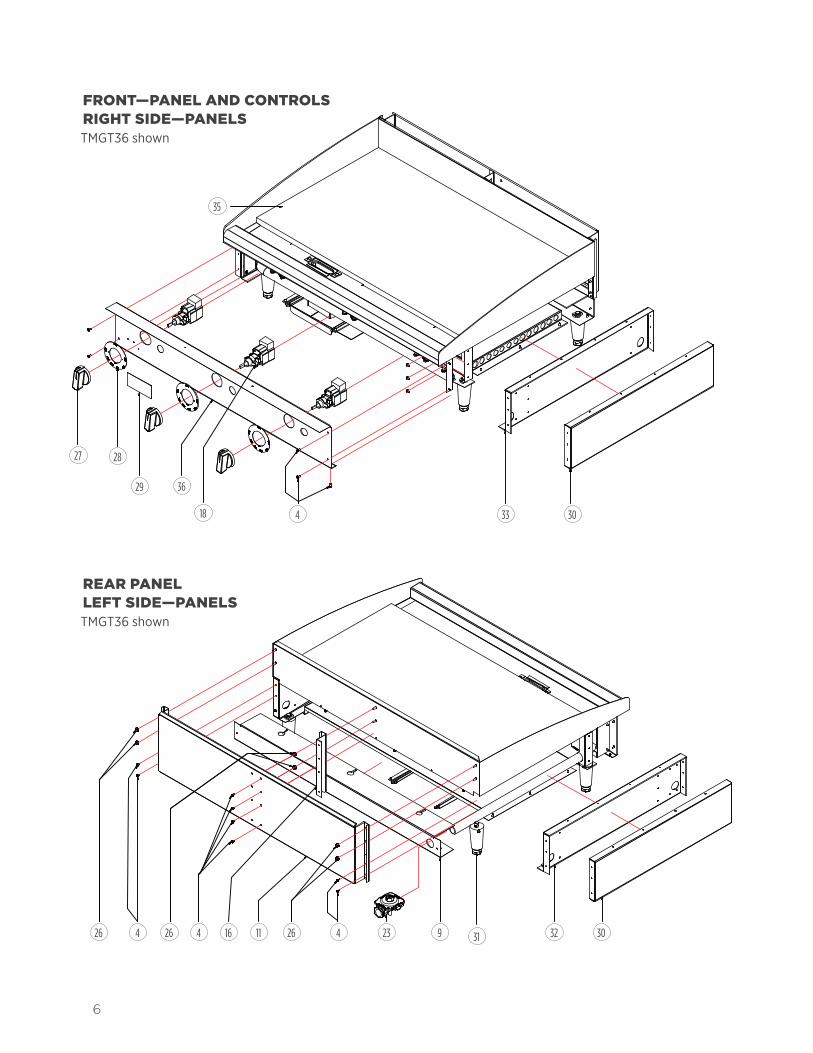
REAR PANEL LEFT SIDE—PANELSTMGT36 shown
30
35
33
303231923444 262626 1116
418
3629
2827
FRONT—PANEL AND CONTROLS RIGHT SIDE—PANELSTMGT36 shown

2M-Z
210
01 R
ev-
Ow
ner's
Man
ual f
or IR
CS4
Impi
ngem
ent/
Rad
iant
Spl
it-B
elt C
onve
yor T
oast
er
7 2M-Z
1296
6 R
ev C
Ow
ner’s
Man
ual f
or T
oast
mas
ter T
MG
M a
nd T
MG
T G
as G
riddl
es
A
BOTTOMTMGT36 shown
134
4
14
1235
1423
18
6
7
1013
17 2122831
31 4
4
3
1927
20 15 14
THERMOSTAT [TMGT ONLY] AND BURNERSTMGT36 shown
THERMOSTAT [TMGT MODELS ONLY]
8
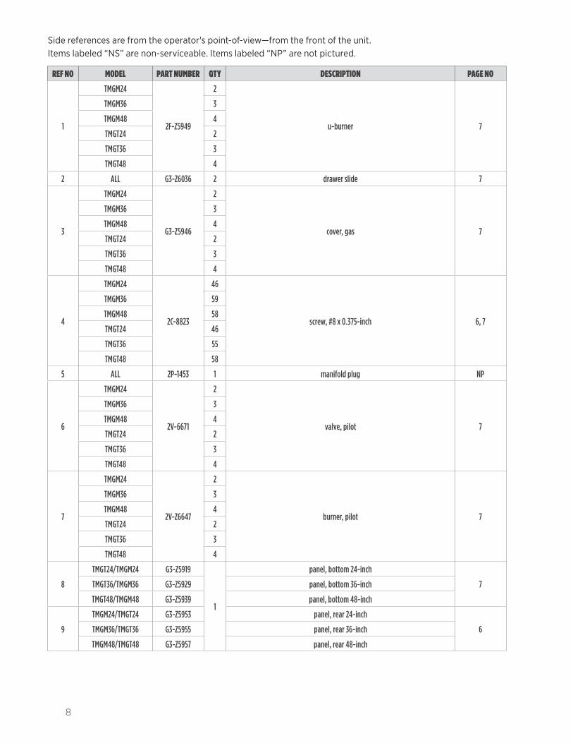
Side references are from the operator's point-of-view—from the front of the unit. Items labeled “NS” are non-serviceable. Items labeled “NP” are not pictured.
REF NO MODEL PART NUMBER QTY DESCRIPTION PAGE NO
1
TMGM24
2F-Z5949
2
u-burner 7
TMGM36 3
TMGM48 4
TMGT24 2
TMGT36 3
TMGT48 4
2 ALL G3-Z6036 2 drawer slide 7
3
TMGM24
G3-Z5946
2
cover, gas 7
TMGM36 3
TMGM48 4
TMGT24 2
TMGT36 3
TMGT48 4
4
TMGM24
2C-8823
46
screw, #8 x 0.375-inch 6, 7
TMGM36 59
TMGM48 58
TMGT24 46
TMGT36 55
TMGT48 58
5 ALL 2P-1453 1 manifold plug NP
6
TMGM24
2V-6671
2
valve, pilot 7
TMGM36 3
TMGM48 4
TMGT24 2
TMGT36 3
TMGT48 4
7
TMGM24
2V-Z6647
2
burner, pilot 7
TMGM36 3
TMGM48 4
TMGT24 2
TMGT36 3
TMGT48 4
8
TMGT24/TMGM24 G3-Z5919
1
panel, bottom 24-inch
7TMGT36/TMGM36 G3-Z5929 panel, bottom 36-inch
TMGT48/TMGM48 G3-Z5939 panel, bottom 48-inch
9
TMGM24/TMGT24 G3-Z5953 panel, rear 24-inch
6TMGM36/TMGT36 G3-Z5955 panel, rear 36-inch
TMGM48/TMGT48 G3-Z5957 panel, rear 48-inch

2M-Z
210
01 R
ev-
Ow
ner's
Man
ual f
or IR
CS4
Impi
ngem
ent/
Rad
iant
Spl
it-B
elt C
onve
yor T
oast
er
9 2M-Z
1296
6 R
ev C
Ow
ner’s
Man
ual f
or T
oast
mas
ter T
MG
M a
nd T
MG
T G
as G
riddl
es
10 ALL G3-624304 1 grease chute 7
11
TMGM24/TMGT24 G5-Z4812
1
flue, 24-inch
6TMGM36/TMGT36 G5-Z4813 flue, 36-inch
TMGM48/TMGT48 G5-Z4814 flue, 48-inch
12
TMGM24
2C-2555
2
nut, #8-32 acorn NP
TMGM36 3
TMGM48 4
TMGT24 2
TMGT36 3
TMGT48 4
13 ALL G3-Y7046 1 grease drawer 7
14
TMGM24 G3-624306
1
manifold, 24-inch without thermostat [manual control]
7
TMGM36 G3-636306 manifold, 36-inch without thermostat [manual control]
TMGM48 G3-648306 manifold, 48-inch without thermostat [manual control]
TMGT24 G3-624307 manifold, 24-inch with thermostat
TMGT36 G3-636307 manifold, 36-inch with thermostat
TMGT48 G3-648307 manifold, 48-inch with thermostat
15
TMGM24
2A-9369
2
fitting, orifice 7
TMGM36 3
TMGM48 4
TMGT24 2
TMGT36 3
TMGT48 4
16
TMGM36
G5-Z4817 1 flue divider 6TMGM48
TMGT36
TMGT48
17
TMGM24
G3-GD0036
2
probe tube assembly NP
TMGM36 3
TMGM48 4
TMGT24 2
TMGT36 3
TMGT48 4
18
TMGT24
2T-Z4293
2
thermostat 6TMGT36 3
TMGT48 4
19
TMGT24
2K-Y7111
2
assembled fitting, 90° 7TMGT36 3
TMGT48 4

10
20
TMGM24
2K-Z4921
2
corrugated burner tube 7
TMGM36 3
TMGM48 4
TMGT24 2
TMGT36 3
TMGT48 4
21
TMGT24
G3-Z4398
2
bulb cap NPTMGT36 3
TMGT48 4
22
TMGT24
2C-6517
6
nut, 1/4-20 NPTMGT36 9
TMGT48 12
23 ALL 2J-Z0792 1 pressure regulator 6, 7
24
TMGT24
G3-Y9531
2
insulator NPTMGT36 3
TMGT48 4
25
TMGM24 G4-Z12942-07
1 nameplate NP
TMGM36 G4-Z12942-08
TMGM48 G4-Z12942-09
TMGT24 G4-Z12942-10
TMGT36 G4-Z12942-11
TMGT48 G4-Z12942-12
26
TMGM24
2C-Z2893
6
nut, #10-24 6
TMGM36 8
TMGM48 8
TMGT24 6
TMGT36 8
TMGT48 8
27
TMGM24
2R-Z13014
2
knob, without thermostat [manual control]
6
TMGM36 3
TMGM48 4
TMGT24
2R-Z13015
2
knob, with thermostatTMGT36 3
TMGT48 4
28
TMGM24
2M-Z21075
2
knob label, without thermostat [manual control]
6
TMGM36 3
TMGM48 4
TMGT24
2M-Z21074
2
knob label, with thermostatTMGT36 3
TMGT48 4

2M-Z
210
01 R
ev-
Ow
ner's
Man
ual f
or IR
CS4
Impi
ngem
ent/
Rad
iant
Spl
it-B
elt C
onve
yor T
oast
er
11 2M-Z
1296
6 R
ev C
Ow
ner’s
Man
ual f
or T
oast
mas
ter T
MG
M a
nd T
MG
T G
as G
riddl
es
29 ALL 2M-Z20970 1 badge, Toastmaster 6
30 ALL G3-Z5945 2 side panel 6
31 ALL 2A-Z5942 4 leg 6, 7
32 ALL G3-624302 2 liner assembly, left 6
33 ALL G3-624303 1 liner assembly, right 6
34
TMGM24/TMGT24 G3-Z5915
1
center wall, 24-inch
7TMGM36/TMGT36 G3-Z5925 center wall, 36-inch
TMGM48/TMGT48 center wall, 48-inch
35
TMGM24 G4-TC0096
1
top weldment, 24-inch without thermostat [manual control]
6, 7
TMGM36 G4-TC0102 top weldment, 36-inch without thermostat [manual control]
TMGM48 G4-TC0105 top weldment, 48-inch without thermostat [manual control]
TMGT24 G4-TC0097 top weldment, 24-inch with thermostat
TMGT36 G4-TC0103 top weldment, 36-inch with thermostat
TMGT48 G4-TC0106 top weldment, 48-inch with thermostat
36
TMGM24 G3-Z15799
1
panel, front 24-inch without thermostat [manual control]
6
TMGM36 G3-Z15807 panel, front 36-inch without thermostat [manual control]
TMGM48 G3-Z15809 panel, front 48-inch without thermostat [manual control]
TMGT24 G3-Z15806 panel, front 24-inch with thermostat
TMGT36 G3-Z15808 panel, front 36-inch with thermostat
TMGT48 G3-Z15810 panel, front 48-inch with thermostat
37 ALL 2C-Z6035 2 bolt, 1/2-13 x 3-inch NP

12
SPECIFICATIONS TMGT36 shown
MODEL HEIGHT WIDTH [A]
DEPTH BTU APPROX. SHIP WEIGHT
APPROX. WEIGHT INSTALLED
TMGM24/ TMGT24
15.5 in. (394 mm)
24 in. (610 mm)
31.75 in. (806 mm)
40,000162 lb.
(73.5 kg)140 lb.
(63.5 kg)
TMGM36/ TMGT36
15.5 in. (394 mm)
36 in. (914 mm)
31.75 in. (806 mm)
60,000232 lb.
(105.2 kg)197 lb.
(89.4 kg)
TMGM48/ TMGT48
15.5 in. (394 mm)
48 in. (1.22 m)
31.75 in. (806 mm)
80,000315 lb.
(142.9 kg)266 lb.
(120.7 kg)
A
2 in. (51 mm)
3.4 in. (86 mm)
6.7 in. (170 mm)
1.2 in. (30 mm)
0.7 in. (18 mm)
4 in. (102 mm)
11.5 in. (292 mm)
4 in. (102 mm) 27.75 in.
(705 mm)

2M-Z
210
01 R
ev-
Ow
ner's
Man
ual f
or IR
CS4
Impi
ngem
ent/
Rad
iant
Spl
it-B
elt C
onve
yor T
oast
er
13 2M-Z
1296
6 R
ev C
Ow
ner’s
Man
ual f
or T
oast
mas
ter T
MG
M a
nd T
MG
T G
as G
riddl
es
4 in. (102 mm)

Printed in the U.S.A. • 2M-Z12966 • Rev C • 06.2016
Specifications are subject to change without notice.
TOASTMASTER • www.ToastmasterCorp.com 10 Sunnen Drive • Saint Louis, Missouri 63143
Telephone 314 678 6347 • Fax 314 781 5445