Embed Size (px)
Citation preview
AC DRIVE SYSTEMTMdrive™-MVMEDIUM VOLTAGE INVERTER
TOSHIBA MITSUBISHI-ELECTRIC INDUSTRIAL SYSTEMS CORPORATION
TOSHIBA MITSUBISHI-ELECTRIC INDUSTRIAL SYSTEMS CORPORATIONMita 43 MT Building 13-16 Mita 3chome, Minato-ku Tokyo 108-0073 Japan
Phone: +81-3-5441-9100
Overseas Sales DepartmentPlant & Projects Sales DepartmentIndustrial Systems DivisionPhone: +81-3-5441-9721 Fax: +81-3-5441-9791
To users of our inverters: Our inverters are designed to control the speeds of three-phase induction motors for general industry.
PRECAUTIONS• Read the entire “Instruction Manual” carefully for important information about safety, handling, installation, operation, maintenance, and parts replacements.
• When using our inverters for equipment such as nuclear power control equipment, aviation and space flight control equipment, traffic equipment, and safety equipment, and there is a risk that any failure or malfunction of the inverter could directly endanger human life or cause injury, please contact our headquarters, branch, or office printed on the front and back covers of this catalogue. Such applications must be studied carefully.
• When using our inverters for critical equipment, even though the inverters are manufactured under strict quality control, always fit your equipment with safety devices to prevent serious accident or loss should the inverter fail (such as failure to issue an inverter trouble signal).
• Do not use our inverters for any load other than three-phase induction motors.
● Windows is a registered trademark of Microsoft Corporation in the United States and/or other countries.● Device Net is a registered trademark of ODVA (Open Device Net Vender Association, Inc.).● Profibus-DP is a trademark of Profibus International.● Modbus Plus is a trademark of Schneider Electric Inc.● Ethernet is a registered trademark of Xerox Corporation.● TOSLINE is a registered trademark of Toshiba Corporation.● TMdrive is a registered trademark of Toshiba Mitsubishi Electric Industrial Systems Corporation.● All other registered trademarks and trademarks are the property of their respective companies.● All specifications in this document subject to change without notice.
A-0006-0404-A( )H

TMdrive-MV is a clean wave inverter.
Direct drive for medium voltage induction motor, realizing high efficiency and high input power factor Power Source and Motor friendly
High Efficiency
High Power Factor
Saving energy
High Reliability
TMdrive-MV Series
TMdrive-MV is a medium voltage IGBT inverter with the concept of “clean wave”.
This inverter has been developed on the basis of the latest “state-of-the-art” AC drive
technology for large industrial plants and the world-renowned advanced technology in
power electronics.
Applying TMdrive-MV instead of a damper or a control valve can achieve a
significant energy saving by driving a medium voltage induction motor at variable
speed for square torque loads such as fan, pump and blower.
Characteristics of TMdrive-MV make them an ideal
variable speed drive for medium voltage motor
including existing motor.
●Harmonic currents are reduced by 18 pulse rectification using a special designed transformer
●The harmonic contents meet IEEE519 requirements●Output current close to sine wave by multi-level PWM technology●No derating of motor output capacity required●Standard motor is applicable since the switching surge voltage is small
owing to unique PWM switching control
●Less harmonic contents reduce the harmonic loss of the motor●Higher efficiency by eliminating output transformer●Higher efficiency by reducing the number of IGBTs
●High power factor by using diode bridge rectifiers (Approx. 95% or more at input transformer primary)
●TMdrive-MV realizes energy saving by variable speed control for square torque loads such as fan, blower and pump as well as by its high efficiency
●By using IGBT with rated voltage of 1700V, the number of parts are reduced and the reliability of main circuit is increased
●Use of 32 bit micro processor (model PP7) specifically designed for power electronics applications reduces the number of parts and increases the reliability of the control

TMdrive-MV Series
Tough operation at a momentary power failure● Ride-through control
• When a momentary power failure and the voltage dip occur, TMdrive-MV can continue
to operate (within 300 msec).
● Automatic restarting function• After input power recovery, the coasting motor can be restarted smoothly and automatically.
User friendly● Easy engineering
• Packaged type design with input transformer
• No harmonic filter required
• No power factor correction capacitor required
• Standard motor applicable
• Smaller output cable size compared with that of conventional LV inverter
● Easy operation and diagnostics• Large LCD display is provided for easy operation
Easy maintenance● Front maintenance
• Each cell inverter can be drawn
out from the front of the panel
● Air cooled type• Each panel is cooled by the cooling
fan mounted on the top of the panel
• Front access type air filters are
provided
● Drawable type cell-inverter construction
TMdrive-MV has many unique features.
What is TMdrive-MV?
● Control board
● Cell-inverter
● Inverter Panel
Reducing the harmonic currents in the input current● Equivalent to 18 pulse rectification● Meet IEEE519 requirements● No power factor correction capacitor and no harmonic filter required
Stable speed control without a speed sensing device● No speed sensor required● New V/f constant control with sensorless vector control enables a stable
speed control● The vector control with a speed sensor (resolver or pulse generator) is
available (option)
TMdrive-MV can drive a standard motor● Retrofit friendly
• Output current of TMdrive-MV close to sine wave by multi-level PWM control
• Small switching surge voltage owing to unique PWM control
• No derating of motor output capacity required
● Direct drive of medium voltage induction motor• No step up transformer required
• By reducing the output current with medium voltage output, the cable size between the inverter
and the motor is reduced compared with that of the conventional LV inverter drive
● Can be used for constant torque and high starting torque applications such as extruder and mixer
● Can be used as a soft starter to solve the following problems• Starting frequency problem due to large load GD2
• Bus voltage drop problem at direct on line starting

Har
mon
ic c
urre
nt c
onte
nts
(%)
Harmonic Number
● Harmonic current contents of input current● Input wave forms of TMdrive-MV
● Harmonic current contents of input current
*1 Result of actual load test (1800kVA)
Individual harmonic order (odd)
TMdrive-MV*1 (%)
IEEE-519(1992) (%)
5th
1.4
4.0
7th
0.5
4.0
11th
0.6
2.0
13th
0.5
2.0
17th
1.1
1.5
19th
0.6
1.5
23th
0.3
0.6
25th
0.5
0.6
● Harmonic current contents of existing system (6.6kV base)
Harmonic order
Harmonic current (%)
Harmonic current (A)
5th
17.5
30.6
7th
11.0
19.2
11th
4.5
7.9
13th
3.0
5.2
17th
1.5
2.6
19th
1.25
2.2
23th
0.75
1.3
25th
0.75
1.3
● Harmonic current contents from TMdrive-MV (6.6kV base)
Harmonic order
Harmonic current (%)
Harmonic current (A)
5th
1.4
2.2
7th
0.5
0.8
11th
0.6
0.9
13th
0.5
0.8
17th
1.1
1.7
19th
0.6
0.9
23th
0.3
0.5
25th
0.5
0.8
● Harmonic current contents after TMdrive-MV added and Allowable upper limit (6.6kV base)
Harmonic order
Total harmonic current contents (A)
Upper limit of harmonic current (A)
5th
32.8
35.0
7th
20.0
25.0
11th
8.8
16.0
13th
6.0
13.0
17th
4.3
10.0
19th
3.1
9.0
23th
1.8
7.6
25th
2.1
7.0
Contract Demand(10000 kW)
Existing GeneralLoad
System AdditionInverter
Existing Harmonics Source
(6 pulse rectifier)5000kVA 2000kVA 1800kVA
Input Voltage 4.00%
3.50%
3.00%
2.50%
2.00%
1.50%
1.00%
0.50%
0.00%5 7 11 13 17 19 23 25
Input Current
Results
IEEE519
TMdrive-MV is a clean wave inverter.● The policy of the Guideline in JapanThe guideline sets the upper limit of harmonic currents level and maintains the harmonic voltage distortion in the electrical power system below the harmonics environment target level. This guideline does not apply to the existing system at the plant, but if additions are made to those systems or the conditions of the contract changes, they become subject to the guideline. If harmonics of those systems exceed the upper limit specified by the guideline, certain measures have to be taken to meet the requirement of the guideline.
TMdrive-MV produces very low harmonic currents and is stress free to power source. Therefore, it can clear the guideline without using any special measures such as the harmonic filters. The case study below shows how much harmonics are produced when applying TMdrive-MV, how to follow the guideline, and example calculations.
Method to comply with the guideline/example calculation
To the existing system(Receiving voltage = 6.6kV, contract demand = 10000kW), installing a 1800kVA inverter additionally.
Existing load condition:● General load: 5000kVA Maximum operation rate 100%
● 6 pulse rectifier load: 2000kVA Maximum operation rate 100%
Addition:● TMdrive-MV: 1800kVA Maximum operation rate 100%
Harmonic currents are reduced by 18 pulse rectification using a special designed transformer.In recent years, use of industrial equipment with power electronics are increasing due to a rapid progress of the semiconductors such as transistors and thyristors. The increasing problems of harmonic currents generated by such large capacity industrial equipment affect the harmonic voltage distortion on the power supply and cause the failure of other equipment.Therefore, there is a movement to establish harmonic regulation standards to reduce harmonic current contents generated from such power electronic equipment.To comply with such requirements, TMdrive-MV is designed to reduce harmonic current contents to the power source. By using a specially designed transformer, TMdrive-MV has 18 pulse rectification and meets the requirements of IEEE-519 (1992) and the guideline established by MITI (Ministry of international Trade and Industry) in Japan.
Clean Input Wave
Features of TMdrive-MV
TMdrive-MV Series
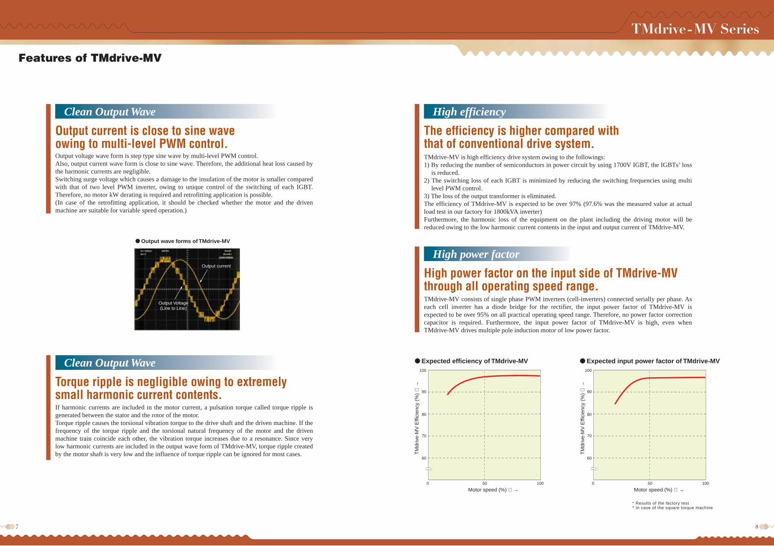
● Expected efficiency of TMdrive-MV ● Expected input power factor of TMdrive-MV
Motor speed (%) →
TM
driv
e-M
V E
ffici
ency
(%
)
→
Motor speed (%) →
* Results of the factory test* In case of the square torque machine
TM
driv
e-M
V E
ffici
ency
(%
)
→
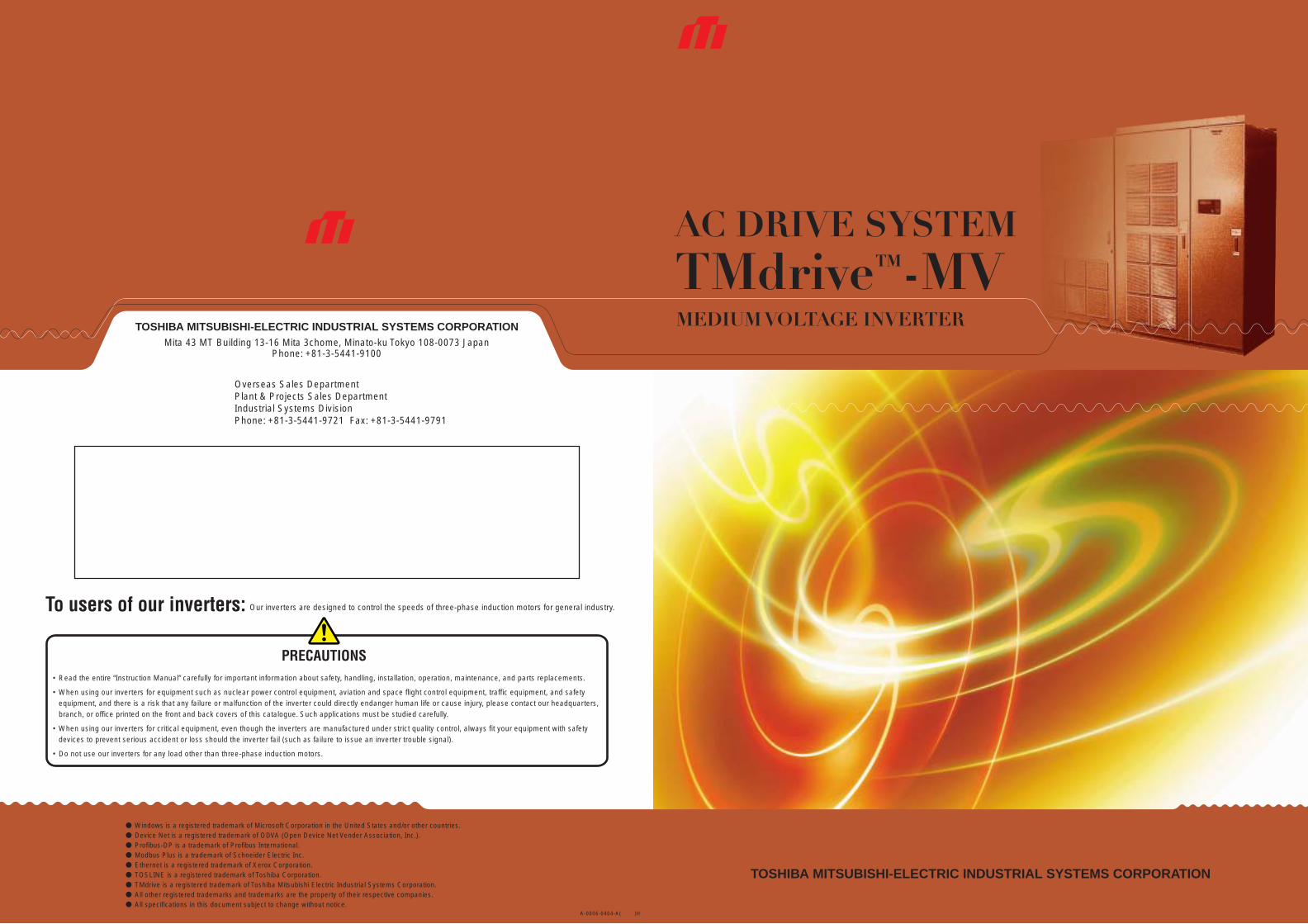
● Output wave forms of TMdrive-MV
100
90
80
70
60
0 50 100
100
90
80
70
60
0 50 100
Output current
Output Voltage(Line to Line)
Output current is close to sine waveowing to multi-level PWM control.Output voltage wave form is step type sine wave by multi-level PWM control.Also, output current wave form is close to sine wave. Therefore, the additional heat loss caused by the harmonic currents are negligible.Switching surge voltage which causes a damage to the insulation of the motor is smaller compared with that of two level PWM inverter, owing to unique control of the switching of each IGBT. Therefore, no motor kW derating is required and retrofitting application is possible.(In case of the retrofitting application, it should be checked whether the motor and the driven machine are suitable for variable speed operation.)
Clean Output Wave
Torque ripple is negligible owing to extremely small harmonic current contents.If harmonic currents are included in the motor current, a pulsation torque called torque ripple is generated between the stator and the rotor of the motor.Torque ripple causes the torsional vibration torque to the drive shaft and the driven machine. If the frequency of the torque ripple and the torsional natural frequency of the motor and the driven machine train coincide each other, the vibration torque increases due to a resonance. Since very low harmonic currents are included in the output wave form of TMdrive-MV, torque ripple created by the motor shaft is very low and the influence of torque ripple can be ignored for most cases.
Clean Output Wave
The efficiency is higher compared with that of conventional drive system.TMdrive-MV is high efficiency drive system owing to the followings:1) By reducing the number of semiconductors in power circuit by using 1700V IGBT, the IGBTs’ loss
is reduced.2) The switching loss of each IGBT is minimized by reducing the switching frequencies using multi
level PWM control.3) The loss of the output transformer is eliminated.The efficiency of TMdrive-MV is expected to be over 97% (97.6% was the measured value at actual load test in our factory for 1800kVA inverter)Furthermore, the harmonic loss of the equipment on the plant including the driving motor will be reduced owing to the low harmonic current contents in the input and output current of TMdrive-MV.
High efficiency
High power factor on the input side of TMdrive-MVthrough all operating speed range.TMdrive-MV consists of single phase PWM inverters (cell-inverters) connected serially per phase. As each cell inverter has a diode bridge for the rectifier, the input power factor of TMdrive-MV is expected to be over 95% on all practical operating speed range. Therefore, no power factor correction capacitor is required. Furthermore, the input power factor of TMdrive-MV is high, even when TMdrive-MV drives multiple pole induction motor of low power factor.
High power factor
TMdrive-MV Series
Features of TMdrive-MV

TMdrive-MV
TMdrive-MV TMdrive-MV
TMdrive-MV
Coke oven
Blower
Waste gas
Steam
Watersupply
Fuel
Steam
Boiler
To end user
Storage reservoir
(Pump)
Ore car
Vibrator
Nozzle
Pump
Conveyor
Ore-washing facility
Air
Dust collector
Coke-oven dust collection facility
● Application to Dust-Collection Blowers as used in Steel Industry
● Application to Induced draft fan (IDF) as used in Boiler
● Application to a waterworks booster pump
● Application to an Ore-Washing Facility
Operation point P0.7 when flow rate Q=0.7
When resistance when flow rate was set to Q=0.7 (70%) by controlling the damper
Air flow resistance R=Q2
Operation point P1 when flow rate Q=1
This shows that by controlling the rotational speed, Q-H curve changed
Operation point P0.7 when flow rate Q=1
Air flow resistance R=Q2
Operation point P'0.7 when flow rate Q=0.7
Flow
Time
Energy saving calculation example★ Electrical energy consumption when damper control is applied
(Motor is assumed to run at the rated speed)General relationship between the air pressure (H) and flow rate (Q) of fan and blower are shown below.(H=1: rated air pressure, Q=1: rated air flow)The shaft power (P1) required when Q=1 is the rated shaft power (kW) of fan (blower).The shaft power (P0.7) required when Q=0.7 is P0.7 = P1 × Q0.7 × H0.7
if the efficiency of fan (blower) is ignored.Therefore, if the motor efficiency is ηM, the input power P11 required when Q=1, and P10.7 when Q=0.7 areP11 = P1 / ηM (kW)P10.7 = P0.7 / ηM (kW)(The motor efficiency drop due to load decrease is ignored.)
★ Electrical energy consumption when variable speed control was applied using TMdrive-MV
When controlling the flow rate of fans and blowers by controlling the variable speed with inverter, the relations are as shown below.The required input power P11 when Q=1 is the same equation as that of the damper control.P11 = P1 / ηM (kW)When the flow rate is 70%=Q'0.7, the required shaft power P'0.7 isP'0.7 = P1 × Q'0.7 × H'
= P1 × Q'0.73
Therefore, the required input power P'10.7 with the inverter efficiency of ηINV isP'10.7 = P'0.7 / ηM/ηINV
★ Calculation ExampleEfficiency of Motor capacity = 96.5%,Efficiency of TMdrive-MV = 97% (including transformer)Shaft power of fan at the rated flow rate: 1100kWFan Characteristics: H = 1.4p.u. when Q=0Annual Run Time: 8000 hoursOperation pattern of Fan:
100%: 20% of annual run time 70%: 50% of annual run time 50%: 30% of annual run time
Electricity Cost: 10 Yen/kWh
● With damper controlP100 for 100% flow rate, P70 for 70% flow rate,P50 for 50% flow rate, thenP100 = 1100 / 0.965 = 1140kWP70 = 1100 × 0.7 × (1.4 – 0.4 × 0.7 × 0.7) / 0.965 = 961kWP50 = 1100 × 0.5 × (1.4 – 0.4 × 0.5 × 0.5) / 0.965 = 741kWThe electricity cost is1140 × 8000 × 0.2 × 10 + 961 × 8000 × 0.5 × 10 + 741 × 8000 × 0.3 × 10 = 74,464,000 Yen
● With variable speed controlP'100 for 100% flow rate, P'70 for 70% flow rate,P'50 for 50% flow rate, thenP'100 = 1100 / 0.965 = 1140kWP'70 = 1100 × 0.73 / 0.965 / 0.97 = 403kWP'50 = 1100 × 0.53 / 0.965 / 0.97 = 147kWThe electricity cost is1140 × 8000 × 0.2 × 10 + 403 × 8000 × 0.5 × 10 + 147 × 8000 × 0.3 × 10 = 37,888,000 Yen
● The cost difference between using the damper and the variable speed control is
74,464,000 – 37,888,000 = 36,576,000 Yen/Year
TMdrive-MV realizes big energy saving by variable speed operation.Squirrel-cage induction motors are predominantly used on fan and pump applications. When
motors are operated at a constant speed with the flow and pressure of the fan or pump controlled
with a damper or control valve, great energy loss results.
Losses can be minimized and large energy savings can be realized with inverter speed control
instead of control by dampers or control valves. With an inverter the following relations exist:
Flow ∝ SpeedRequired power ∝ Flow3
For example, at 80% flow (speed), power required=(0.8)3=50%.
A small flow or speed change, therefore, can result in a significant energy savings.
..
TMdrive-MV Series
Contributing to saving energy

● Maintenance tool functionsDrive equipment can be easily adjusted and maintained using the personal computer (Windows®2000 or Windows®XP). Moreover, several sets of drives can be maintained with Ethernet.
Large LCD display is adopted for the operation panel.
The operating conditions can be monitored on the operation panel.
The parameter settings and the failure diagnostics are easy.
Simple operation and maintenance with Operation Panel
Operation panel
Loading and saving of set point file
Main menu
Selection of test operation
Control block display: overview
Fault traceback
Input of set point
Step response
The functions of the operation panel are as follows.
● LCD graphic display<240×64 dots>• Display of operating conditions• Display of starting, fault and alarm conditions• Display of parameters
«Main functions»• Input and change of the parameters• Display mode change• Local/remote selection
● Operational status LED display
● Ethernet connector
● Analog signal Pins• Current feedback signal: 2ch• User selectable signal for monitor: 5ch
● Interlock switch with protective cover
● Fault reset switch
Maintenance Tool (Option)
First fault•Online manualSnapshot
Control block display: speed control
● Support function• Control block display• Trend display• Snap shot function• Test operation with simulated signal• Response wave display
● Set point control• Change of parameter• Loading and saving of set
point file• Comparison between set
point files
● Troubleshooting• First fault display• Operation preparation
display• Fault traceback• Trouble records• Fault history display• Online manual
TMdrive-MV Series
Operation panel of TMdrive-MV

Standard connection
Standard interface
<Customer→TMdrive-MV>
<TMdrive-MV→Customer>
Main power supplyControl power supplyStart/Stop signalEmergency stop signalStatus of incoming CBStatus of outgoing CB (if any)
Speed reference signal
Power of main circuit
Power of control circuit
Close: Run and Open: Stop
Open: Emergency Stop (Free run stop)
Close: Circuit breaker close
Close: Circuit breaker close
0–10VDC=0–100% or
4–20mADC=0–100%
AC200V–3ph-50Hz or AC200/220V-3ph-60Hz
Dry contact, DC24V–12mA
Dry contact, DC24V–12mA
Dry contact, DC24V–12mA
Dry contact, DC24V–12mA (in the case of system which outgoing CB is required in inverter output)
Input impedance 1M ohm (in the case of voltage signal input)
Input impedance 10 ohm (in the case of current signal input)
Inverter ready signalRun signalFault signalTrip signal for incoming CBOutput currentMotor speed
Close: Inverter ready
Close: Run and Open: Stop
Close: Inverter heavy fault
Close: To trip incoming CB
4–20mADC=0–125% of rated current
4–20mADC=0–125% of rated current
Dry contact
Max.AC220V–0.8A,DC110V–0.2A,DC24V–1.5A
Load impedance < 500 ohm
Load impedance < 500 ohm
TMdrive-MV (3kV Class)
Input transformer
Input transformer
Cell-inverter
TMdrive-MV (6kV Class)
TMdrive™-MV IMTMdrive™-MV IM
Main circuit configurationThe main circuit of TMdrive-MV consists of the special designed input transformer and single phase PWM inverters (cell-inverters). TMdrive-MV of 3.3kV output consists three cell-inverters connected serially per phase and TMdrive-MV of 6.6kV output consists 6 cell-inverters connected serially per phase.
Control block diagramSensor less vector control will enable a stable speed control. Use of 32 bit micro processor (model PP7) specifically designed for power electronics applications supports the high reliable control.
(Optional control)A vector control system with sensor is available for applications requiring high-precision speed control or those requiring larger starting torque. Simple open loop V/f control is also available.
System configuration1) Motor is operated only by TMdrive-MV. 2) Motor is operated by TMdrive-MV as well
as by a commercial power supply.
This configuration is recommended for the following applications.1. When a redundant power supply is required.2. When a rated speed operation is also required for a certain period.
Speed referenceACC. & Dec. rate
Speec controlTorque ref.
Magnetizing function
Mag. ref.
Volt control
Output frequency
Speed cal.
Cal. of current ref.
Current ref.Current control
Volt referencePWM control
Inverter
Current F.B.K.
Volt cal.
Volt ref.
Main power supply3/3.3kV-3ph-50/60Hz
Control power supply200VAC-3ph-50Hz200/220VAC-3ph-60Hz
Start/Stop signal
Emergency stop signal
Speed reference signal0-10V
4-20A
Control circuit
Input transformer
Ground detection
<Control & Outgoing Panel>
Output frequency
Output speed
Incoming CB“Close”
To tripCircuit of incoming CB
Trip signal for incoming CB
Control circuit
Each panel
Power supply unit
Heavy fault
Run signal
Ready signal
<Incoming Panel> <Transformer Panel> <Inverter Panel> <Control & Outgoing Panel>
FAULT
RUN
READY
TMdrive-MV Series
Main circuit configuration of TMdrive-MV

Width(mm) Depth(mm)
3.3kV-200 – 400kVA 2200 1805
3.3kV-500, 700kVA 2200 1805
3.3kV-900kVA 2200 2005
3.3kV-1200 – 1800kVA 2700 2005
3.3kV-2400, 3000kV 3400 3005
6.6kV-400 – 800kVA 2200 1805
6.6kV-1000, 1400kVA 3200 1805
6.6kV-1800kVA 3200 2005
6.6kV-2400 – 3600kVA 4800 2005
6.6kV-4200 – 6000kVA 5600 3005
2300
2300
5000 3600 600
14009200
7500 600
1400
7200
15300
● 3.3kV-1200kVA, 1500kVA, 1800kVA<Approx. weight: 7000kg>
● 6.6kV-400kVA, 600kVA, 800kVA<Approx. weight: 4200kg>
● 6.6kV-1000kVA, 1400kVA<Approx. weight: 6000kg>
● 3.3kV-4200kVA<Approx. weight: 17000kg>
● 3.3kV-2400kVA, 3000kVA<Approx. weight: 9400kg>
● 3.3kV-200kVA, 300kVA, 400kVA<Approx. weight: 3000kg>
● 3.3kV-500kVA, 700kVA<Approx. weight: 3600kg>
● 3.3kV-900kVA<Approx. weight: 4100kg>
Front view Right side view
Incoming&transformer panel
Inverter panel
Control&outgoing panel
Front view Right side view
Incoming&transformer panel
Inverter panel
Control&outgoing panel
Front view Right side view
Incoming&transformer panel
Inverter panel
Control&outgoing panel
Front view Right side view
Incoming&transformer panel
Inverter panel
Control&outgoing panel
Front view Right side view
Incoming&transformer panel
Inverter panel
Control&outgoing panel
Front view Right side view
Incoming&transformer panel
Inverter panel
Control&outgoing panel
● Approx. dimension of Back to back arrangement
(Note)1. TMdrive-MV is a front maintenance type construction. The
following maintenance space is required on the front side of the panels.Below 3.3kV-1800kVA and 6.6kV-3600kVA: over 1700mmAbove 3.3kV-2100kVA and 6.6kV-4200kVA: over 2000mm
2. Over 700mm of space is required for cooling between the top of the panel and ceiling.
3. Shipping split of TMdrive-MV is between the transformer panel and the inverter panel.
4. The transformer and the transformer panel are to be shipped separately.
5. The back to back arrangement of the panels will be available. (optional)
Front view Right side view
Incoming&transformer panel
Inverter panel
Control&outgoing panel
Front view Right side view
Incoming&transformer panel
Inverter panel
Control&outgoing panel
Front view Right side view
Incoming&transformer panel
Inverter panel
Control&outgoing panel
Front view Right side view
Incoming&transformer panel
Incoming&transformer panel
Inverter panel
Inverter panel
Control&outgoing panel
Front view Right side view
Incoming&transformer panel
Incoming&transformer panel
Inverter panel
Inverter panel
Control&outgoing panel
Front view Right side view
Incoming&transformer panel
Inverter panel
Control&outgoing panel
● 6.6kV-1800kVA <Approx. weight: 7000kg>
● 6.6kV-2400kVA, 3000kVA, 3600kVA <Approx. weight: 13400kg>
● 6.6kV-4200kVA, 4800kVA, 5400kVA, 6000kVA <Approx. weight: 22000kg>
● 6.6kV-8500kVA <Approx. weight: 32000kg>
1600
3200
TMdrive-MV Series
Outline dimensions of TMdrive-MV unit: mm

Voltage class
3.3kV Output Capacity (kVA)
3.0kV Output Capacity (kVA)
Rated output current (A)
Motor power output (kW)
Voltage class
6.6kV Output Capacity (kVA)
6.0kV Output Capacity (kVA)
Rated output current (A)
Motor power output (kW)
Output frequency (Hz)
Overload capacity
Main circuit
Control circuit
Tolerance
Power factor of Main power supply
Control method
Frequency precision
Torque characteristics of load
Acceleration/deceleration time
Main control functions
Main protective functions
Data Transmission
Display
Push buttons
Input transformer
Protection degree of Enclosure
Panel construction
Cooling
Panel color
Ambient temperature
Humidity
Altitude
Vibration
Installation
Application
Standards
200
180
35
160
400
360
35
315
300
270
53
250
600
540
53
450
400
360
70
315
800
720
70
650
500
450
88
400
1000
900
88
850
700
630
123
560
1400
1270
123
1120
900
810
158
750
1800
1630
158
1400
1000
900
175
800
2000
1810
175
1600
1200
1090
210
1000
2400
2180
210
2000
1500
1360
263
1250
3000
2720
263
2500
1800
1630
315
1400
3600
3270
315
2800
2000
1810
350
1600
4000
3630
350
3150
2400
2180
420
2000
4200
3810
368
3550
3000
2720
525
2500
4800
4360
420
4000
3400
3090
595
2800
5400
4900
473
4500
4200
3810
735
3550
6000
5450
525
5000
6800
6180
595
5600
8500
7720
744
7100
Item Standard specifications
3300/3000V
6600/6000V
Outp
utIn
put
Cont
rol S
peci
ficat
ion
Oper
atio
n bo
ard
Cons
truct
ion
Ambi
ent C
ondi
tions
*1
*2
50 or 60 Hz
125%-60sec.
3 phase 3000/3300V-50/60Hz or 3 phase 6000/6600V-50/60Hz
3 phase 200V-50Hz or 3 phase 200/220V-60Hz
Voltage: ±10%, Frequency: ±5%
Approx. 95% or more at normal operating speed
Sensorless vector control + Multi-level sinusoidal PWM (Pulse Width Modulation)
±0.5% of maximum output frequency (Analogue input)
Square torque load, Constant torque load
0.1 ~ 3270 sec. (depend on GD2 of load machine)
Soft stall (Automatic load reduction control during overload), Ride-through function, Specific Frequency Evasion Function,
Total run time display function, Non-stop operation during speed reference loss, Multiple Acc./Dcc. Rate setting
Current limit, Overcurrent, Overvoltage, Overload, Undervoltage, Ground fault, CPU error, Cooling fan abnormal
DeviceNet, ProfiBus-DP, ModbusPlus, TOSLINE-S20
LCD display
3 LED's (READY, RUN, FAULT/ALARM)
NAVIGATION keyboard, CONTROLS keyboard
Start, Stop, Reset Fault, INTERLOCK (Emergency stop)
Temperature class H, dry type, tapping range ±5%, only for TMdrive-MV
IP20 (IEC-529)
Free standing, front maintenance type
Air cooled by ventilation fans mounted on panels
Munsell 5Y7/1
0 ~ 40˚C
Max. 85% (No condensation)
1000 m above sea level or less
0.5G or less at 10 ~ 50Hz
Indoor
Fan, Blower, Pump, Compressor, Extruder, Mixer etc.
Electrical performance: IEC
Components and others: JIS, JEC, JEM
*3
*3
(Note) *1 Approximate capacity in the case of 3.3kV, 4-pole standard induction machine.*2 Approximate capacity in the case of 6.6kV, 4-pole standard induction machine.*3 Some specification of 3.3kV-3400, 4200kVA and 6.6kV-6800, 8500kVA differ from standard designs. For details, please contact our company representatives.
★ Please designate the following items on your inquiry. (1) Application (specific load equipment or line name)(2) Type of load equipment (fan, blower, pump, compressor, etc.)
(3) Torque characteristics of the load equipment (Square torque, Linear torque, Constant torque, etc.)
Load Inertia on motor shaft basis (GD2): (kg·m2)
Speed-torque curve of the load equipment: (kg·m2)
(4) Driving MotorNew or Existing: Power Output: (kW) Number of Poles: (P)
Rated Current: (A) Rated Voltage: (V) Rated Speed: (min-1)
Rated Frequency: (Hz)
(5) Main Circuit Input Voltage-Frequency: (V)– (Hz)
(6) Control Power Supply Voltage-Frequency: 3 Phase 3 Line–200V–50Hz or 200/220V–60Hz
(7) Range of Operating Frequency: Hz ~ Hz
(8) Operating Frequency Reference Signal (automatic signal (4~20mA), manual setting on the control panel, contact
signals to increase or decrease speed, etc.)
(9) Commercial Bypass Operation (Yes or No)
(10) Environmental ConditionsAmbient Temperature: ~ ˚C Relative Humidity: (%) (Non-condensing)
Ventilation System (Yes or No) Space Limitation for transportation on site:
(11) Overload requirement % of motor rated output for seconds
Output frequency
Control method
Maintenance tool
Others
Max. frequency 120Hz
Vector control with speed sensor (Resolver, Pulse generator), V/f control
Automatic flying restart (for a power failure between 300msec and 6sec)Synchronous transfer (Transfer motor to line, Transfer line to motor)
Personal computer software for maintenance and adjustment (OS: Windows®2000, Windows®XP)
Separate installation of input transformer: Please consult our company representatives
Specified panel painting color
Control panel outlet, Control panel illumination light, space heater
Specifications Option
Items to be Informed
★ Inverter capacity calculationIf the rated current of the motor that the inverter is going to drive is I (A), and the related voltage V (kV), the necessary capacity of the inverter (kVA) is calculated by
Inverter capacity (kVA) = √3 × V × I .... (1)The capacity of inverter must be larger than the capacity calculated from (1).The rated capacity of TMdrive-MV listed in this catalogue is calculated by
Rated capacity (kVA) = √3 × 3.3 (or 6.6) kV × Maximum continuous current (A)Therefore, if the output voltage is 3kV (or 6kV), the inverter capacity is
Rated capacity × 3 / 3.3 (or Rated capacity × 6 / 6.6)which means that the capacity is derated when to use at 3kV.
TMdrive-MV Series
Specifications of TMdrive-MV