Embed Size (px)
Citation preview

16 Esquire Road, Billerica, MA 01862 Phone 978-284-3906 Email: [email protected]
May 17, 2017
Melanie A. Bachman Executive Director Connecticut Siting Council 10 Franklin Street New Britain, CT 06051
Regarding: Notice of Exempt Modification – Swap of 3 Antennas, Removing (3) TMAs, Addition of (6) TMAs and addition of associated lines
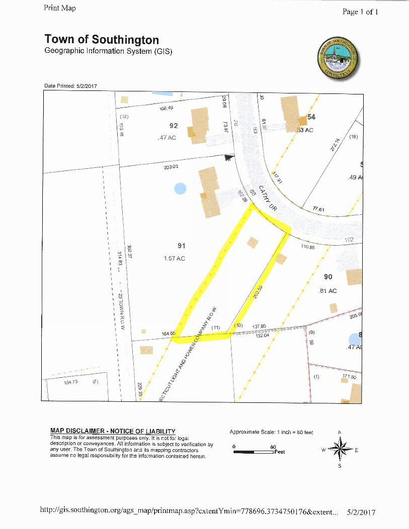
Property Address: 102 Cathy Drive, Southington, CT (the “Property”) Applicant: AT&T Mobility (“AT&T” Site: CT1109) Dear Ms. Bachman: AT&T currently maintains a wireless telecommunications facility on an existing 81 foot utility tower (“tower”) at the above-referenced address, latitude 41.59886111, longitude -72.8524444. AT&T’s facility consists of three (6) wireless telecommunications antennas at 91 feet. The tower is controlled and owned by Eversource Energy. Assessor’s information is attached hereto. AT&T desires to modify its existing telecommunications facility by swapping three (3) antennas, removing (3) TMAs, adding (6) TMAs, and adding associated lines. The centerline height of said antennas is and will remain at 91 feet.
Please accept this application as notification pursuant to R.C.S.A. § 16-50j-73, for construction that constitutes an exempt modification pursuant to R.C.S.A. § 16-50j-72 (b)(2). In accordance with R.C.S.A. § 16-50j-73, a copy of this letter is being sent to the Town Manager of the Town of Southington, the Chief Building Official of the Town of Southington, and the Zoning Enforcement Officer of the Town of Southington. A copy of this letter is also being sent to Eversource Energy, the owner of the structure that AT&T is located.
The planned modifications to AT&T’s facility fall squarely within those activities explicitly provided for in R.C.S.A. § 16-50j-72(b)(2).
1. The planned modifications will not result in an increase in the height of the existing structure. AT&T’s antennas and associated lines will be installed at 91 foot level of the 81 foot utility tower.
2. The proposed modifications will not involve any changes to ground-mounted equipment and, therefore will not require an extension of the site boundary.
3. The proposed modification will not increase the noise level at the facility by six decibel or more, or to levels that exceed state and local criteria.

16 Esquire Road, Billerica, MA 01862 Phone 978-284-3906 Email: [email protected]
4. The operation of the modified facility will not increase radio frequency (RF) emissions at the facility to a level at or above the Federal Communications Commission (FCC) safety standard. An RF emissions calculation is attached.
5. The proposed modifications will not cause a change or alteration in the physical or environmental characteristics of the site.
6. The tower and its foundation can support AT&T’s proposed modifications. (Please see attached Structural analysis completed by Centek Engineering Dated April 13, 2017).
For the foregoing reasons AT&T respectfully requests that the proposed swap of 3 antennas,
removal of (3) TMAs, the addition of (6) TMAs, and addition of associated lines be allowed within the exempt modifications under R.C.S.A. § 16-50j-72(b)(2). Sincerely, Nicole Caplan Site Acquisition Specialist Empire Telecom CC: Garry Brumback, Town Manager, Town of Southington John Smigel, Chief Building Official, Town of Southington Matthew A. Reimondo, Zoning Enforcement Officer, Town of Southington Eversource Energy, c/o Joel Szarkowicz

1 8
TITLE SHEET
CT1109 - LTE 2CSOUTHINGTON-CATHYDRIVE NU
EVERSOURCE UTILITY STRUCT. NO.: 4119CATHY DRIVE
SOUTHINGTON, CT 06489
WIRELESS COMMUNICATIONS FACILITY
PROJECTLOCATION
NORTH
GENERAL NOTES
VICINITY MAP SCALE: 1" = 1000'
PROJECT INFORMATION
REV.DESCRIPTIONSHT. NO.
SHEET INDEX
PROJECT SUMMARY

8
NOTES ANDSPECIFICATIONS
2

8
PLANS ANDELEVATION
3

8
LTE 2CANTENNADETAILS
4

8
LTE 2CEQUIPMENT
DETAILS
RRU (REMOTE RADIO UNIT)
5
FRONT SIDE BOTTOM
ALPHA/BETA/GAMMA ANTENNA
SURGE ARRESTOR
SIDEFRONT BOTTOM
PENTAPLEXER

86
LTE SCHEMATICDIAGRAM
AND NOTES
® ™

87
LTE WIRINGDIAGRAM
“ ”

88
TYPICALELECTRICAL
DETAILS

S t r u c t u r a l A n a l y s i s o fA n t e n n a M a s t a n d T o w e r
A T & T S i t e R e f : C T 1 1 0 9
E v e r s o u r c e S t r u c t u r e N o . 4 1 1 9
8 1 ’ E l e c t r i c T r a n s m i s s i o n L a t t i c e T o w e r
C a t h y D r i v eS o u t h i n g t o n , C T
C E N T E K P r o j e c t N o . 1 7 0 0 4 . 0 4
D a t e : J a n u a r y 2 7 , 2 0 1 7R e v 1 : A p r i l 1 3 , 2 0 1 7
Prepared for:AT&T Mobil ity
500 Enterprise Dr ive, Suite 3ARocky Hil l , CT 06067

CENTEK Engineering, Inc.Structural Analysis – 81-ft Eversource Tower # 4119AT&T Antenna Upgrade – CT1109Southington, CTRev 1 ~ April 13, 2017
TABLE OF CONTENTS TOC-1
T a b l e o f C o n t e n t sSECTION 1 - REPORT§ INTRODUCTION§ PRIMARY ASSUMPTIONS USED IN THE ANALYSIS§ ANALYSIS§ DESIGN BASIS§ RESULTS§ CONCLUSIONSECTION 2 - CONDITIONS & SOFTWARE§ STANDARD ENGINEERING CONDITIONS§ GENERAL DESCRIPTION OF STRUCTURAL ANALYSIS PROGRAMS§ RISA 3-D§ PLS TOWER
SECTION 3 - DESIGN CRITERIA§ CRITERIA FOR DESIGN OF PCS FACILITIES ON OR EXTENDING ABOVE
METAL ELECTRIC TRANSMISSON TOWERS§ NU DESIGN CRITERIA TABLE§ PCS SHAPE FACTOR CRITERIA§ WIRE LOADS SHEETSECTION 4 - DRAWINGS§ TOWER DRAWINGSSECTION 5 - TIA-222-G LOAD CALCULATIONS FOR ANTENNA MAST
ANALYSIS§ ANTENNA MAST WIND & ICE LOADSECTION 6 - ANTENNA MAST ANALYSIS PER TIA-222G§ LOAD CASES AND COMBINATIONS (TIA/EIA LOADING)§ RISA 3-D ANALYSIS REPORT§ ANTENNA MAST CONNECTION TO TOWER

CENTEK Engineering, Inc.Structural Analysis – 81-ft Eversource Tower # 4119AT&T Antenna Upgrade – CT1109Southington, CTRev 1 ~ April 13, 2017
TABLE OF CONTENTS TOC-2
SECTION 7 - NECS/NU LOAD CALCULATIONS FOR UTILITYSTRUCTURE ANALYSIS
§ EQUIPMENT WIND LOAD CALCULATIONSECTION 8 - ANTENNA MAST ANALYSIS PER NESC/NU FOR
OBTAINING PCS STRUCTURE REACTIONS APPLIED TOUTILITY TOWER
§ LOAD CASES AND COMBINATIONS (NESC/NU LOADING)§ RISA 3-D ANALYSIS REPORTSECTION 9 - PLS TOWER RESULTS FROM MAST REACTIONS
CALCULATED IN RISA WITH NESC/NU CRITERIA§ COAX CABLE LOAD ON CL&P TOWER CALCULATION§ PLS REPORT§ LOCAL MEMBER STRESS ANALYSIS§ FOUNDATION ANALYSISSECTION 10 - REFERENCE MATERIAL§ RFDS DATA SHEET§ EQUIPMENT CUT SHEETS

CENTEK Engineering, Inc.Structural Analysis – 81-ft Eversource Tower # 4119AT&T Antenna Upgrade – CT1109Southington, CTRev 1 ~ April 13, 2017
REPORT SECTION 1-1
I n t r o d u c t i o nThe purpose of this report is to analyze the existing antenna mast and 81’ utility tower located on CathyDrive in Southington, CT for the proposed antenna and equipment upgrade by AT&T.
The existing and proposed loads consist of the following:
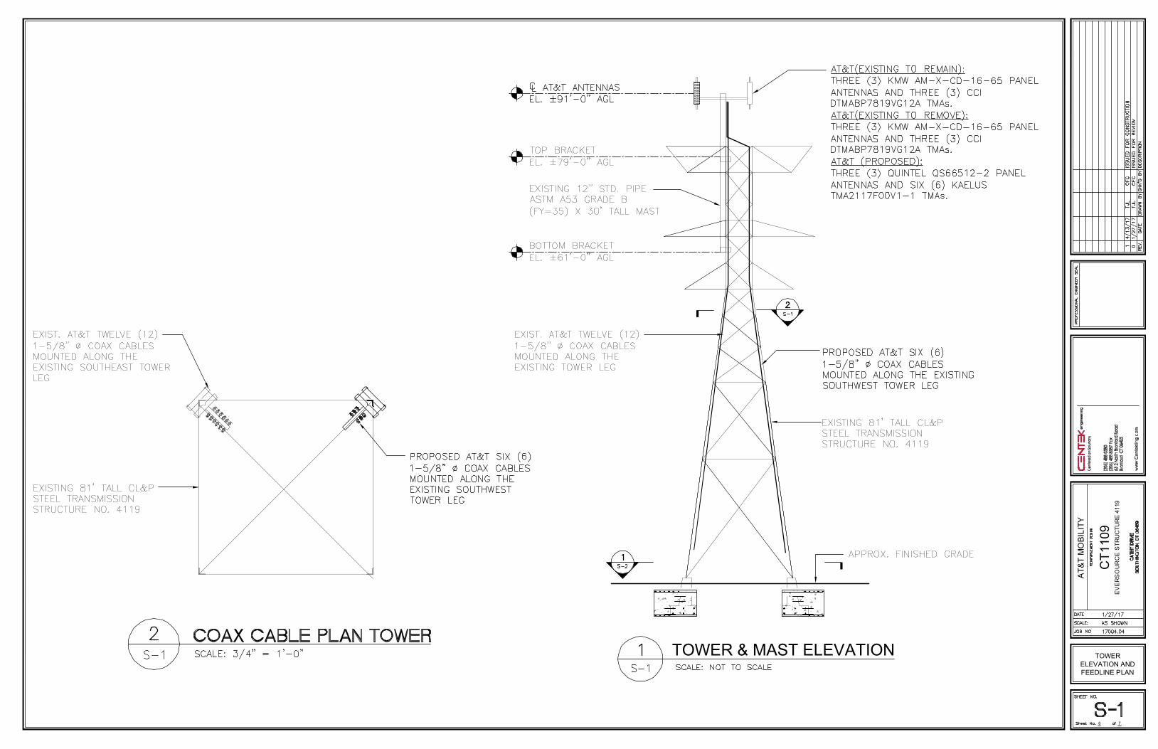
§ AT&T (Existing to Remain):Antennas: Three (3) KMW AM-X-CD-16-65-00T panel antennas and three (3) CCIDTMABP7819VG12A TMAs mounted on a T-Arm array with a RAD center elevation of 91-ftabove tower base.Coax Cables: Twelve (12) 1-5/8” Æ coax cables running on a leg of the existing tower.
§ AT&T (Existing to Remove):Antennas: Three (3) KMW AM-X-CD-16-65-00T panel antennas and three (3) CCIDTMABP7819VG12A TMAs mounted on a T-Arm array with a RAD center elevation of 91-ftabove tower base.
§ AT&T (Proposed):Antennas: Three (3) Quintel QS66512-2 panel antennas and six (6) KaelusTMA2117F00V1-1 TMAs mounted on a T-Arm array with a RAD center elevation of 91-ftabove tower base.Coax Cables: Six (6) 1-5/8” Æ coax cables running on a leg of the existing tower.
P r i m a r y a s s u m p t i o n s u s e d i n t h e a n a l y s i s§ ASCE Manual No. 10-97, “Design of Latticed Steel Transmission Structures”, defines steel
stresses for evaluation of the utility tower.§ All utility tower members are adequately protected to prevent corrosion of steel members.§ All proposed antenna mounts are modeled as listed above.§ All coaxial cable will be installed within the antenna mast unless specified otherwise.§ Antenna mast will be properly installed and maintained.§ No residual stresses exist due to incorrect tower erection.§ All bolts are appropriately tightened providing the necessary connection continuity.§ All welds conform to the requirements of AWS D1.1.§ Antenna mast and utility tower will be in plumb condition.§ Utility tower was properly installed and maintained and all members were properly designed,
detailed, fabricated, and installed and have been properly maintained since erection.§ Any deviation from the analyzed loading will require a new analysis for verification of
structural adequacy.
CENTEK Engineering, Inc.Structural Analysis – 81-ft Eversource Tower # 4119AT&T Antenna Upgrade – CT1109Southington, CTRev 1 ~ April 13, 2017
REPORT SECTION 1-2
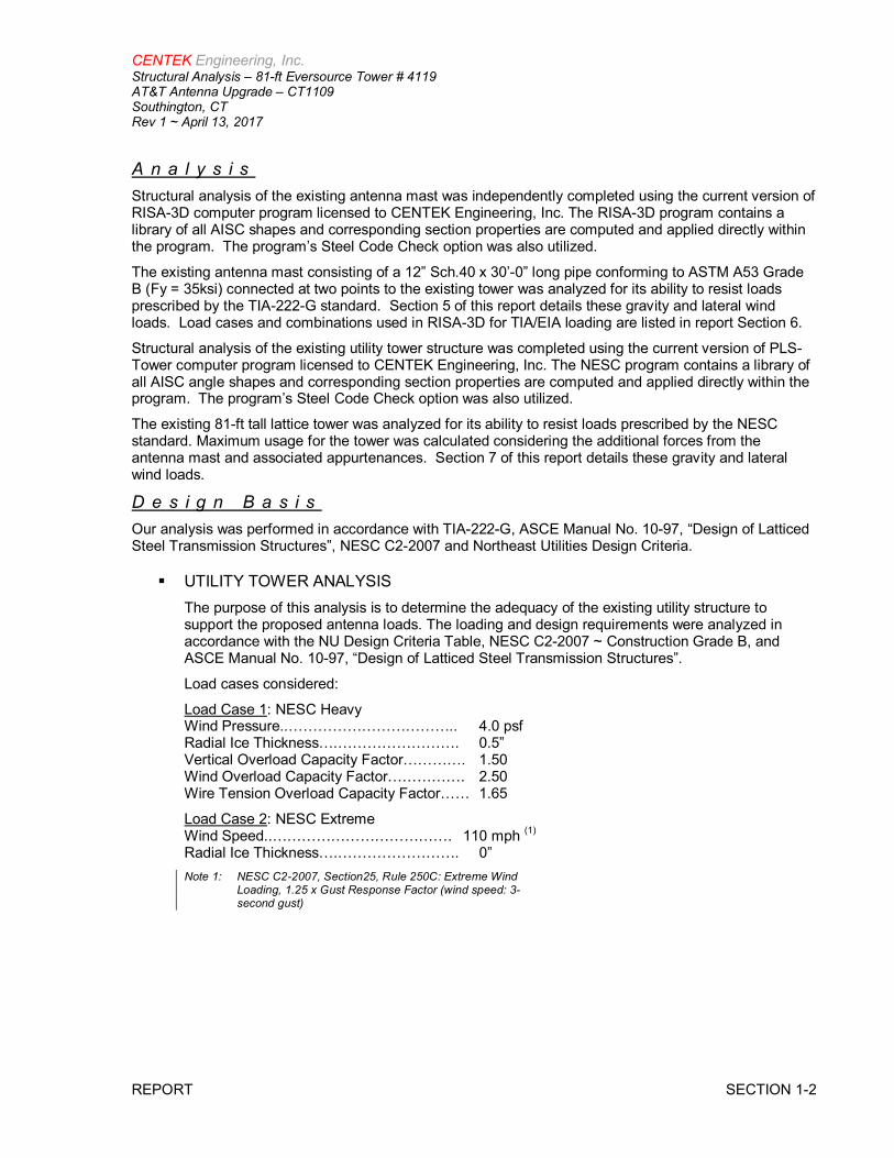
A n a l y s i sStructural analysis of the existing antenna mast was independently completed using the current version ofRISA-3D computer program licensed to CENTEK Engineering, Inc. The RISA-3D program contains alibrary of all AISC shapes and corresponding section properties are computed and applied directly withinthe program. The program’s Steel Code Check option was also utilized.
The existing antenna mast consisting of a 12” Sch.40 x 30’-0” long pipe conforming to ASTM A53 GradeB (Fy = 35ksi) connected at two points to the existing tower was analyzed for its ability to resist loadsprescribed by the TIA-222-G standard. Section 5 of this report details these gravity and lateral windloads. Load cases and combinations used in RISA-3D for TIA/EIA loading are listed in report Section 6.
Structural analysis of the existing utility tower structure was completed using the current version of PLS-Tower computer program licensed to CENTEK Engineering, Inc. The NESC program contains a library ofall AISC angle shapes and corresponding section properties are computed and applied directly within theprogram. The program’s Steel Code Check option was also utilized.
The existing 81-ft tall lattice tower was analyzed for its ability to resist loads prescribed by the NESCstandard. Maximum usage for the tower was calculated considering the additional forces from theantenna mast and associated appurtenances. Section 7 of this report details these gravity and lateralwind loads.
D e s i g n B a s i sOur analysis was performed in accordance with TIA-222-G, ASCE Manual No. 10-97, “Design of LatticedSteel Transmission Structures”, NESC C2-2007 and Northeast Utilities Design Criteria.
§ UTILITY TOWER ANALYSISThe purpose of this analysis is to determine the adequacy of the existing utility structure tosupport the proposed antenna loads. The loading and design requirements were analyzed inaccordance with the NU Design Criteria Table, NESC C2-2007 ~ Construction Grade B, andASCE Manual No. 10-97, “Design of Latticed Steel Transmission Structures”.
Load cases considered:
Load Case 1: NESC HeavyWind Pressure..…………………………….. 4.0 psfRadial Ice Thickness….……………………. 0.5”Vertical Overload Capacity Factor…………. 1.50Wind Overload Capacity Factor……………. 2.50Wire Tension Overload Capacity Factor…… 1.65
Load Case 2: NESC ExtremeWind Speed..………………………………. 110 mph (1)
Radial Ice Thickness….……………………. 0”Note 1: NESC C2-2007, Section25, Rule 250C: Extreme Wind
Loading, 1.25 x Gust Response Factor (wind speed: 3-second gust)

CENTEK Engineering, Inc.Structural Analysis – 81-ft Eversource Tower # 4119AT&T Antenna Upgrade – CT1109Southington, CTRev 1 ~ April 13, 2017
REPORT SECTION 1-3
§ MAST ASSEMBLY ANALYSISMast, appurtenances and connections to the utility tower were analyzed and designed inaccordance with the NU Design Criteria Table, TIA/EIA-222-G and AISC standards.
Load cases considered:
Load Case 1:Wind Speed………………………………... 97 mph (2016 CSBC Appendix-N)
Radial Ice Thickness….……………………. 0”
Load Case 2:Wind Pressure..……………………………. 50 mph wind pressureRadial Ice Thickness….…………………….. 1.00”
R e s u l t s
§ ANTENNA MASTThe existing antenna mast was determined to be structurally adequate.
§ UTILITY TOWERThis analysis finds that the subject utility structure is adequate to support the proposedantenna mast and related appurtenances. The tower stresses meet the requirements setforth by the ASCE Manual No. 10-97, “Design of Latticed Steel Transmission Structures”, forthe applied NESC Heavy and Hi-Wind load cases. The detailed analysis results are providedin Section 8 of this report. The analysis results are summarized as follows:
A maximum usage of 81.86% occurs in the utility structure under the NESC Extreme loadingcondition.
TOWER SECTION:The utility structure was found to be within allowable limits.
§ FOUNDATION AND ANCHORSThe existing foundation consists of four (4) 1-ft 8-in square tapering to 2-ft 4-in square x 5.25-ftlong reinforced concrete piers and four (4) 5-ft square x 2-ft thick reinforced concrete pads. Thebase of the tower is connected to the foundation by one (1) anchor stub angle per leg. Foundationinformation was obtained from Northeast Utilities drawing 01064-60003.
Component DesignLimit
Stress Ratio(percentage of capacity) Result
12” Sch 40 Pipe Bending 46.9% PASSConnection to Tower Shear 15.7% PASS
Tower Member Stress Ratio(% of capacity) Result
Angle g17X 81.86% PASS

CENTEK Engineering, Inc.Structural Analysis – 81-ft Eversource Tower # 4119AT&T Antenna Upgrade – CT1109Southington, CTRev 1 ~ April 13, 2017
REPORT SECTION 1-4
BASE REACTIONS:From PLS-Tower analysis of CL&P tower based on NESC/EVERSOURCE prescribed loads.
Load Case Shear Uplift Compression
NESC Heavy Wind 8.61 kips 15.43 kips 33.69 kipsNESC Extreme Wind 14.61 kips 48.40 kips 56.82 kips
Note 1 – 10% increase to be applied to the above tower base reactions for foundation verification per OTRM 051
FOUNDATION:The existing foundations were found to be structurally inadequate. Reinforcement of the existingfoundation with 9-ft square by 5-ft thick reinforced concrete mats at each tower leg is required.
Note 1: FS denotes Factor of SafetyNote 2: 10% increase to PLS base reactions used in foundation analysis per OTRM 051.
C o n c l u s i o nThis analysis shows that the subject utility tower with the reinforcements detailed in section 4 of thereport is adequate to support the proposed AT&T equipment upgrade.
The analysis is based, in part on the information provided to this office by Eversource and AT&T. If theexisting conditions are different than the information in this report, CENTEK engineering, Inc. must becontacted for resolution of any potential issues.
Please feel free to call with any questions or comments.
Respectfully Submitted by:
Timothy J. Lynn, PEStructural Engineer
Foundation DesignLimit
AllowableLimit
ProposedLoading (2)
Result
Conc. Pad &Pier Uplift 1.0 FS (1) 1.25 FS (1) PASS

CENTEK Engineering, Inc.Structural Analysis – 81-ft Eversource Tower # 4119AT&T Antenna Upgrade – CT1109Southington, CTRev 1 ~ April 13, 2017
CONDITIONS & SOFTWARE SECTION 2-1
S T A N D A R D C O N D I T I O N S F O R F U R N I S H I N G O FP R O F E S S I O N A L E N G I N E E R I N G S E R V I C E S O NE X I S T I N G S T R U C T U R E S
All engineering services are performed on the basis that the information used is current and correct. Thisinformation may consist of, but is not necessarily limited to:
§ Information supplied by the client regarding the structure itself, its foundations, the soil conditions, theantenna and feed line loading on the structure and its components, or other relevant information.
§ Information from the field and/or drawings in the possession of CENTEK engineering, Inc. orgenerated by field inspections or measurements of the structure.
§ It is the responsibility of the client to ensure that the information provided to CENTEK engineering,Inc. and used in the performance of our engineering services is correct and complete. In the absenceof information to the contrary, we assume that all structures were constructed in accordance with thedrawings and specifications and are in an un-corroded condition and have not deteriorated. It istherefore assumed that its capacity has not significantly changed from the “as new” condition.
§ All services will be performed to the codes specified by the client, and we do not imply to meet anyother codes or requirements unless explicitly agreed in writing. If wind and ice loads or other relevantparameters are to be different from the minimum values recommended by the codes, the client shallspecify the exact requirement. In the absence of information to the contrary, all work will beperformed in accordance with the latest revision of ANSI/ASCE10 & ANSI/EIA-222.
§ All services are performed, results obtained, and recommendations made in accordance withgenerally accepted engineering principles and practices. CENTEK engineering, Inc. is notresponsible for the conclusions, opinions and recommendations made by others based on theinformation we supply.

CENTEK Engineering, Inc.Structural Analysis – 81-ft Eversource Tower # 4119AT&T Antenna Upgrade – CT1109Southington, CTRev 1 ~ April 13, 2017
CONDITIONS & SOFTWARE SECTION 2-2
G E N E R A L D E S C R I P T I O N O F S T R U C T U R A LA N A L Y S I S P R O G R A M ~ R I S A - 3 D
RISA-3D Structural Analysis Program is an integrated structural analysis and design software package forbuildings, bridges, tower structures, etc.
Modeling Features:
§ Comprehensive CAD-like graphic drawing/editing capabilities that let you draw, modify andload elements as well as snap, move, rotate, copy, mirror, scale, split, merge, mesh, delete,apply, etc.
§ Versatile drawing grids (orthogonal, radial, skewed)§ Universal snaps and object snaps allow drawing without grids§ Versatile general truss generator§ Powerful graphic select/unselect tools including box, line, polygon, invert, criteria,
spreadsheet selection, with locking§ Saved selections to quickly recall desired selections§ Modification tools that modify single items or entire selections§ Real spreadsheets with cut, paste, fill, math, sort, find, etc.§ Dynamic synchronization between spreadsheets and views so you can edit or view any data
in the plotted views or in the spreadsheets§ Simultaneous view of multiple spreadsheets§ Constant in-stream error checking and data validation§ Unlimited undo/redo capability§ Generation templates for grids, disks, cylinders, cones, arcs, trusses, tanks, hydrostatic
loads, etc.§ Support for all units systems & conversions at any time§ Automatic interaction with RISASection libraries§ Import DXF, RISA-2D, STAAD and ProSteel 3D files§ Export DXF, SDNF and ProSteel 3D files
Analysis Features:
§ Static analysis and P-Delta effects§ Multiple simultaneous dynamic and response spectra analysis using Gupta, CQC or SRSS
mode combinations§ Automatic inclusion of mass offset (5% or user defined) for dynamic analysis§ Physical member modeling that does not require members to be broken up at intermediate
joints§ State of the art 3 or 4 node plate/shell elements§ High-end automatic mesh generation — draw a polygon with any number of sides to create a
mesh of well-formed quadrilateral (NOT triangular) elements.§ Accurate analysis of tapered wide flanges - web, top and bottom flanges may all taper
independently§ Automatic rigid diaphragm modeling§ Area loads with one-way or two-way distributions§ Multiple simultaneous moving loads with standard AASHTO loads and custom moving loads
for bridges, cranes, etc.§ Torsional warping calculations for stiffness, stress and design§ Automatic Top of Member offset modeling§ Member end releases & rigid end offsets§ Joint master-slave assignments§ Joints detachable from diaphragms§ Enforced joint displacements§ 1-Way members, for tension only bracing, slipping, etc.

CENTEK Engineering, Inc.Structural Analysis – 81-ft Eversource Tower # 4119AT&T Antenna Upgrade – CT1109Southington, CTRev 1 ~ April 13, 2017
CONDITIONS & SOFTWARE SECTION 2-3
§ 1-Way springs, for modeling soils and other effects§ Euler members that take compression up to their buckling load, then turn off.§ Stress calculations on any arbitrary shape§ Inactive members, plates, and diaphragms allows you to quickly remove parts of structures
from consideration§ Story drift calculations provide relative drift and ratio to height§ Automatic self-weight calculations for members and plates§ Automatic subgrade soil spring generator
Graphics Features:
§ Unlimited simultaneous model view windows§ Extraordinary “true to scale” rendering, even when drawing§ High-speed redraw algorithm for instant refreshing§ Dynamic scrolling stops right where you want§ Plot & print virtually everything with color coding & labeling§ Rotate, zoom, pan, scroll and snap views§ Saved views to quickly restore frequent or desired views§ Full render or wire-frame animations of deflected model and dynamic mode shapes with
frame and speed control§ Animation of moving loads with speed control§ High quality customizable graphics printing
Design Features:
§ Designs concrete, hot rolled steel, cold formed steel and wood§ ACI 1999/2002, BS 8110-97, CSA A23.3-94, IS456:2000,EC 2-1992 with consistent bar sizes
through adjacent spans§ Exact integration of concrete stress distributions using parabolic or rectangular stress blocks§ Concrete beam detailing (Rectangular, T and L)§ Concrete column interaction diagrams§ Steel Design Codes: AISC ASD 9th, LRFD 2nd & 3rd, HSS Specification, CAN/CSA-S16.1-
1994 & 2004, BS 5950-1-2000, IS 800-1984, Euro 3-1993 including local shape databases§ AISI 1999 cold formed steel design§ NDS 1991/1997/2001 wood design, including Structural Composite Lumber, multi-ply, full
sawn§ Automatic spectra generation for UBC 1997, IBC 2000/2003§ Generation of load combinations: ASCE, UBC, IBC, BOCA, SBC, ACI§ Unbraced lengths for physical members that recognize connecting elements and full lengths
of members§ Automatic approximation of K factors§ Tapered wide flange design with either ASD or LRFD codes§ Optimization of member sizes for all materials and all design codes, controlled by standard or
user-defined lists of available sizes and criteria such as maximum depths§ Automatic calculation of custom shape properties§ Steel Shapes: AISC, HSS, CAN, ARBED, British, Euro, Indian, Chilean§ Light Gage Shapes: AISI, SSMA, Dale / Incor, Dietrich, Marino\WARE§ Wood Shapes: Complete NDS species/grade database§ Full seamless integration with RISAFoot (Ver 2 or better) for advanced footing design and
detailing§ Plate force summation tool

CENTEK Engineering, Inc.Structural Analysis – 81-ft Eversource Tower # 4119AT&T Antenna Upgrade – CT1109Southington, CTRev 1 ~ April 13, 2017
CONDITIONS & SOFTWARE SECTION 2-4
Results Features:
§ Graphic presentation of color-coded results and plotted designs§ Color contours of plate stresses and forces with quadratic smoothing, the contours may also
be animated§ Spreadsheet results with sorting and filtering of: reactions, member & joint deflections, beam
& plate forces/stresses, optimized sizes, code designs, concrete reinforcing, materialtakeoffs, frequencies and mode shapes
§ Standard and user-defined reports§ Graphic member detail reports with force/stress/deflection diagrams and detailed design
calculations and expanded diagrams that display magnitudes at any dialed location§ Saved solutions quickly restore analysis and design results.

CENTEK Engineering, Inc.Structural Analysis – 81-ft Eversource Tower # 4119AT&T Antenna Upgrade – CT1109Southington, CTRev 1 ~ April 13, 2017
CONDITIONS & SOFTWARE SECTION 2-5
G E N E R A L D E S C R I P T I O N O F S T R U C T U R A LA N A L Y S I S P R O G R A M ~ P L S - T O W E R
PLS-TOWER is a Microsoft Windows program for the analysis and design of steel latticed towersused in electric power lines or communication facilities. Both self-supporting and guyed towerscan be modeled. The program performs design checks of structures under user specified loads.For electric power structures it can also calculate maximum allowable wind and weight spans andinteraction diagrams between different ratios of allowable wind and weight spans.
Modeling Features:
§ Powerful graphics module (stress usages shown in different colors)§ Graphical selection of joints and members allows graphical editing and checking§ Towers can be shown as lines, wire frames or can be rendered as 3-d polygon surfaces§ Can extract geometry and connectivity information from a DXF CAD drawing§ CAD design drawings, title blocks, drawing borders or photos can be tied to structure model§ XML based post processor interface§ Steel Detailing Neutral File (SDNF) export to link with detailing packages§ Can link directly to line design program PLS-CADD§ Automatic generation of structure files for PLS-CADD§ Databases of steel angles, rounds, bolts, guys, etc.§ Automatic generation of joints and members by symmetries and interpolations§ Automated mast generation (quickly builds model for towers that have regular repeating
sections) via graphical copy/paste§ Steel angles and rounds modeled either as truss, beam or tension-only elements§ Guys are easily handled (can be modeled as exact cable elements)
Analysis Features:
§ Automatic handling of tension-only members§ Automatic distribution of loads in 2-part suspension insulators (v-strings, horizontal vees, etc.)§ Automatic calculation of tower dead, ice, and wind loads as well as drag coefficients
according to:§ ASCE 74-1991§ NESC 2002§ NESC 2007§ IEC 60826:2003§ EN50341-1:2001 (CENELEC)§ EN50341-3-9:2001 (UK NNA)§ EN50341-3-17:2001 (Portugal NNA)§ ESAA C(b)1-2003 (Australia)§ TPNZ (New Zealand)§ REE (Spain)§ EIA/TIA 222-F§ ANSI/TIA 222-G§ CSA S37-01
§ Automated microwave antenna loading as per EIA/TIA 222-F and ANSI/TIA 222-G§ Minimization of problems caused by unstable joints and mechanisms§ Automatic bandwidth minimization and ability to solve large problems§ Design checks according to (other standards can be added easily):
§ ASCE Standard 10-90

CENTEK Engineering, Inc.Structural Analysis – 81-ft Eversource Tower # 4119AT&T Antenna Upgrade – CT1109Southington, CTRev 1 ~ April 13, 2017
CONDITIONS & SOFTWARE SECTION 2-6
§ AS 3995 (Australian Standard 3995)§ BS 8100 (British Standard 8100)§ EN50341-1 (CENELEC, both empirical and analytical methods are available)§ ECCS 1985§ NGT-ECCS§ PN-90/B-03200§ EIA/TIA 222-F§ ANSI/TIA 222-G§ CSA S37-01§ EDF/RTE Resal§ IS 802 (India Standard 802)
Results Features:
§ Design summaries printed for each group of members§ Easy to interpret text, spreadsheet and graphics design summaries§ Automatic determination of allowable wind and weight spans§ Automatic determination of interaction diagrams between allowable wind and weight spans§ Capability to batch run multiple tower configurations and consolidate the results§ Automated optimum angle member size selection and bolt quantity determinationTool for interactive angle member sizing and bolt quantity determination.

CENTEK Engineering, Inc.Structural Analysis – 81-ft Eversource Tower # 4119AT&T Antenna Upgrade – CT1109Southington, CTRev 1 ~ April 13, 2017
DESIGN CRITERIA SECTION 3-1
C r i t e r i a f o r D e s i g n o f P C S F a c i l i t i e s O n o rE x t e n d i n g A b o v e M e t a l E l e c t r i c T r a n s m i s s i o nT o w e r s & A n a l y s i s o f T r a n s m i s s i o n T o w e r sS u p p o r t i n g P C S M a s t s (1)
I n t r o d u c t i o n
This criteria is the result from an evaluation of the methods and loadings specified by the separatestandards, which are used in designing telecommunications towers and electric transmission towers. Thatevaluation is detailed elsewhere, but in summary; the methods and loadings are significantly different.This criteria specifies the manner in which the appropriate standard is used to design PCS facilitiesincluding masts and brackets (hereafter referred to as “masts”), and to evaluate the electric transmissiontowers to support PCS masts. The intent is to achieve an equivalent level of safety and security under theextreme design conditions expected in Connecticut and Massachusetts.
ANSI Standard TIA-222 covering the design of telecommunications structures specifies a workingstrength/allowable stress design approach. This approach applies the loads from extreme weatherloading conditions, and designs the structure so that it does not exceed some defined percentage offailure strength (allowable stress).
ANSI Standard C2-2007 (National Electrical Safety Code) covering the design of electric transmissionmetal structures is based upon an ultimate strength/yield stress design approach. This approach appliesa multiplier (overload capacity factor) to the loads possible from extreme weather loading conditions, anddesigns the structure so that it does not exceed its ultimate strength (yield stress).
Each standard defines the details of how loads are to be calculated differently. Most of the NU effort in“unifying” both codes was to establish what level of strength each approach would provide, and thenincreasing the appropriate elements of each to achieve a similar level of security under extreme weatherloadings.
Two extreme weather conditions are considered. The first is an extreme wind condition (hurricane) basedupon a 50-year recurrence (2% annual probability). The second is a winter condition combining wind andice loadings.
The following sections describe the design criteria for any PCS mast extending above the top of anelectric transmission tower, and the analysis criteria for evaluating the loads on the transmission towerfrom such a mast from the lower portions of such a mast, and loads on the pre-existing electric lowerportions of such a mast, and loads on the pre-existing electric transmission tower and the conductors itsupports.
Note 1: Prepared from documentation provide from Northeast Utilities.

CENTEK Engineering, Inc.Structural Analysis – 81-ft Eversource Tower # 4119AT&T Antenna Upgrade – CT1109Southington, CTRev 1 ~ April 13, 2017
DESIGN CRITERIA SECTION 3-2
P C S M a s t
The PCS facility (mast, external cable/trays, including the initial and any planned future support platforms,antennas, etc. extending the full height above the top level of the electric transmission structure) shall bedesigned in accordance with the provisions of TIA 222-G:
E L E C T R I C T R A N S M I S S I O N T O W E R
The electric transmission tower shall be analyzed using yield stress theory in accordance with theattached table titled “NU Design Criteria”. This specifies uniform loadings (different from the TIA loadings)on the each of the following components of the installed facility:
§ PCS mast for its total height above ground level, including the initial and planned futuresupport platforms, antennas, etc. above the top of an electric transmission structure.
§ Conductors are related devices and hardware.
§ Electric transmission structure. The loads from the PCS facility and from the electricconductors shall be applied to the structure at conductor and PCS mast attachmentpoints, where those load transfer to the tower.
The uniform loadings and factors specified for the above components in the table are based upon theNational Electrical Safety Code 2007 Edition Extreme Wind (Rule 250C) and Combined Ice and Wind(Rule 250B-Heavy) Loadings. These provide equivalent loadings compared to TIA and its loads andfactors with the exceptions noted above. (Note that the NESC does not require the projected windsurfaces of structures and equipment to be increased by the ice covering.)
In the event that the electric transmission tower is not sufficient to support the additional loadings of thePCS mast, reinforcement will be necessary to upgrade the strength of the overstressed members.

Northeast Utilities Overhead Transmission Standards
____________________________________________________________
Communication Antennas on Transmission Structures (CL&P & WMECo Only)OTRM 059 Northeast Utilities
Approved by: KMS (NU) Design
NU Confidential Information Page 7 of 9 Rev.1
03/17/2011
Attachment A
NU Design Criteria
Bas
ic W
ind
Spee
d
Pre
ssur
e
Hei
ght F
acto
r
Gus
t Fac
tor
Load
or S
tress
Fac
tor
Forc
e C
oef -
Sha
pe F
acto
r
V (MPH) Q (PSF) Kz Gh
TIA(.75Wi)
Conductors:
TIA
/EIA
Antenna Mount 85 TIA TIA TIA
TIA, Section 3.1.1.1
disallowed for connection
design
TIA
Conductors:
Conductors:
1.6 Flat Surfaces 1.3 Round Surfaces
1.6 Flat Surfaces 1.3 Round Surfaces
1.6 Flat Surfaces 1.3 Round Surfaces
1.6 Flat Surfaces 1.3 Round Surfaces
Tower/Pole Analysis with antennas extending above top
of Tower/Pole (Yield Stress)
Tower/Pole Analysis with Antennas below top of
Tower/Pole (on two faces)
Tower/Pole Analysis with antennas extending above top
of Tower/Pole
TIA
/EIA
Antenna Mount
Tower/Pole Analysis with Antennas below top of
Tower/Pole
4 1.00
4 1.00
Conductor loads provided by NU
1.00 2.50-----
1.00
Use NESC C2-2007, Section 25, Rule 250C: Extreme Wind Loading
Conductor loads provided by NU
TIA TIA
Height above ground level based on top of Tower/Pole
TIA, Section 3.1.1.1
disallowed for connection
design
TIA
2.50
TIA
------
NES
C E
xtre
me
Ice
with
Win
d C
ondi
ton*
4PSF Wind Load Height above ground level based on top of Tower/Pole
NE
SC H
eavy
Ice
Con
ditio
nH
igh
Win
d C
ondt
ion
NE
SC E
xtre
me
Win
d
Use NESC C2-2007, Section 25, Rule 250C: Extreme Wind Loading1.25 x Gust Response Factor
Height above ground level based on top of Mast/Antenna
* Only for Structures Installed after 2007
1.6 Flat Surfaces 1.3 Round Surfaces
4PSF Wind Load 1.25 x Gust Response FactorHeight above ground level based on top of Mast/Antenna
Tower/Pole Analysis with Antennas below top of
Tower/Pole
Use NESC C2-2007, Section 25, Rule 250D: Extreme Ice with Wind Loading1.6 Flat Surfaces
1.3 Round Surfaces
Tower/Pole Analysis with antennas extending above top
of Tower/Pole
Use NESC C2-2007, Section 25, Rule 250D: Extreme Ice with Wind Loading
Conductor loads provided by NU

Northeast Utilities Overhead Transmission Standards
____________________________________________________________
Communication Antennas on Transmission Structures (CL&P & WMECo Only)OTRM 059 Northeast Utilities
Approved by: KMS (NU) Design
NU Confidential Information Page 3 of 9 Rev.1
03/17/2011
Shape Factor Criteria shall be per TIA Shape Factors.
2) STEP 2 - The electric transmission structure analysis and evaluation shall be performed in accordance with NESC requirements and shall include the mast and antenna loads determined from NESC applied loading conditions (not TIA/EIA Loads) on the structure and mount as specified below, and shall include the wireless communication mast and antenna loads per NESC criteria)
The structure shall be analyzed using yield stress theory in accordance with Attachment A, “NU Design Criteria.” This specifies uniform loadings (different from the TIA loadings) on each of the following components of the installed facility: a) Wireless communication mast for its total height above ground level, including the initial
and any planned future equipment (Support Platforms, Antennas, TMA’s etc.) above the top of an electric transmission structure.
b) Conductors and related devices and hardware (wire loads will be provided by NU). c) Electric Transmission Structure
i) The loads from the wireless communication equipment components based on NESC and NU Criteria in Attachment A, and from the electric conductors shall be applied to the structure at conductor and wireless communication mast attachment points, where those loads transfer to the tower.
ii) Shape Factor Multiplier:
iii) When Coaxial Cables are mounted along side the pole structure, the shape multiplier shall be:
d) The uniform loadings and factors specified for the above components in Attachment A,
“NU Design Criteria” are based upon the National Electric Safety Code 2007 Edition Extreme Wind (Rule 250C) and Combined Ice and Wind (Rule 250B-Heavy) Loadings. These provide equivalent loadings compared to the TIA and its loads and factors with the exceptions noted above. Note: The NESC does not require ice load be included in the supporting structure. (Ice on
conductors and shield wire only, and NU will provide these loads). e) Mast reaction loads shall be evaluated for local effects on the transmission structure
members at the attachment points.
NESC Structure Shape Cd
Polyround (for polygonal steel poles) 1.3
Flat 1.6
Open Lattice 3.2
Mount Type Cable Cd Pole Cd
Coaxial Cables on outside periphery (One layer) 1.45 1.45
Coaxial Cables mounted on stand offs 1.6 1.3


7
AT&
TM
OBI
LITY
CT1
109
EV
ER
SO
UR
CE
STR
UC
TUR
E41
19
TITLE SHEETTITLE SHEET
1
PROJECTLOCATION
FOUNDATION REINFORCEMENT DESIGN
STRUCT. NO. 4119CATHY DRIVE
SOUTHINGTON, CT 06489
EVERS URCE

7
AT&
TM
OBI
LITY
CT1
109
EV
ER
SO
UR
CE
STR
UC
TUR
E41
19
DESIGN BASISAND GENERAL
NOTES
2

7
AT&
TM
OBI
LITY
CT1
109
EV
ER
SO
UR
CE
STR
UC
TUR
E41
19
EARTHWORK ANDFOUNDATION
CONSTRUCTIONNOTES
3

7
AT&
TM
OBI
LITY
CT1
109
EV
ER
SO
UR
CE
STR
UC
TUR
E41
19
CONCRETECONSTRUCTION
NOTES
4

7
AT&
TM
OBI
LITY
CT1
109
EV
ER
SO
UR
CE
STR
UC
TUR
E41
19
MODIFICATIONINSPECTION
REQUIREMENTS
5
7
AT&
TM
OBI
LITY
CT1
109
EV
ER
SO
UR
CE
STR
UC
TUR
E41
19
TOWERELEVATION ANDFEEDLINE PLAN
6
TOWER & MAST ELEVATION

7
AT&
TM
OBI
LITY
CT1
109
EV
ER
SO
UR
CE
STR
UC
TUR
E41
19
FOUNDATIONREINFORCEMENT
DETAILS
7

Subject:
Location:
Rev. 0: 1/26/17
Loads on AT&T Equipmnet Structure #4119
Southington, CT
Prepared by: T.J.L. Checked by: C.F.C.Job No. 17004.04
Development of Design Heights, Exposure Coefficients,and Velocity Pressures Per TIA-222-G
Wind Speeds
Basic Wind Speed V 97:= mph (User Input - 2016 CSBC Appendix N)Basic Wind Speed with Ice Vi 50:= mph (User Input per Annex B of TIA-222-G)
Input
Structure Type = Structure_Type Lattice:= (User Input)
Structure Category = SC III:= (User Input)
Exposure Category = Exp C:= (User Input)
Structure Height = h 81:= ft (User Input)
Height to Center of Antennas = zAT&T 91:= ft (User Input)
Radial Ice Thickness = ti 1.00:= in (User Input per Annex B of TIA-222-G)
Radial Ice Density = Id 56.00:= pcf (User Input)
Topograpic Factor = Kzt 1.0:= (User Input)
Ka 1.0:= (User Input)
Gust Response Factor = GH 1.35:= (User Input)Output
Wind Direction Probability Factor = Kd 0.95 Structure_Type Pole=if
0.85 Structure_Type Lattice=if
0.85=:= (Per Table 2-2 ofTIA-222-G)
Importance Factors = IWind 0.87 SC 1=if
1.00 SC 2=if
1.15 SC 3=if
1.15=:= (Per Table 2-3 ofTIA-222-G)
IWind_w_Ice 0 SC 1=if
1.00 SC 2=if
1.00 SC 3=if
1=:=
Iice 0 SC 1=if
1.00 SC 2=if
1.25 SC 3=if
1.25=:=
KizzAT&T
33
æçè
ö÷ø
0.1
1.107=:=
tiz 2.0 ti× Iice× Kiz× Kzt0.35
× 2.767=:=
Velocity P ressure Coefficient = KzAT&T 2.01zAT&T
zg
æçè
ö÷ø
æçè
ö÷ø
2α
1.241=:=
Velocity P ressure w/o Ice = qzAT&T 0.00256 Kd× KzAT&T× Kzt× V2
× IWind× 29.213=:=
Velocity P ressure with Ice = qzice.AT&T 0.00256 Kd× KzAT&T× Kzt× Vi2
× IWind_w_Ice× 6.75=:=
TIA RevG Load Calculations.xmcd.xmcd Page 5-1

Subject:
Location:
Rev. 0: 1/26/17
Loads on AT&T Equipmnet Structure #4119
Southington, CT
Prepared by: T.J.L. Checked by: C.F.C.Job No. 17004.04
Development of Wind & Ice Load on Mast
Mast Data: (Pipe 12" SCH. 40) (User Input)
Mast Shape = Round (User Input)
Mast Diameter = Dmast 12.75:= in (User Input)
Mast Length = Lmast 30:= ft (User Input)
Mast Thickness = tmast 0.375:= in (User Input)
Mast Aspect Ratio = Armast12LmastDmast
28.2=:=
Mast Force Coefficient = Camast 1.2=
Wind Load (without ice)
sf/ftMast Projected Surface Area = Amast
Dmast12
1.063=:=
Total Mast Wind Force = qzAT&T GH× Camast× Amast× 50= plf BLC 5
Wind Load (with ice)
Mast Projected Surface Area w/ Ice = AICEmastDmast 2 tiz×+( )
121.524=:= sf/ft
Total Mast Wind Force w/ Ice = qzice.AT&T GH× Camast× AICEmast× 17= plf BLC 4
Gravity Loads (without ice)
Weight of the mast = Self Weight (Computed internally by Risa-3D) plf BLC 1
Gravity Loads (ice only)
Ice Area per Linear Foot = Aimastπ4
Dmast tiz 2×+( )2Dmast
2-é
ëùû 134.9=:= sq in
Weight of Ice on Mast = WICEmast IdAimast
144× 52=:= plf BLC 3
TIA RevG Load Calculations.xmcd.xmcd Page 5-2

Subject:
Location:
Rev. 0: 1/26/17
Loads on AT&T Equipmnet Structure #4119
Southington, CT
Prepared by: T.J.L. Checked by: C.F.C.Job No. 17004.04
Development of Wind & Ice Load on Antennas
Antenna Data:
Antenna Model = KMW AM-X-CD-16-65-00T
Antenna Shape = Flat (User Input)
Antenna Height = Lant 72:= in (User Input)
Antenna Width = Want 11.8:= in (User Input)
Antenna Thickness = Tant 5.9:= in (User Input)
Antenna Weight = WTant 48.5:= lbs (User Input)
Number of Antennas = Nant 3:= (User Input)
Antenna Aspect Ratio = ArantLantWant
6.1=:=
Antenna Force Coefficient = Caant 1.36=
Wind Load (without ice)
Surface Area for One Antenna = SAantLant Want×
1445.9=:= sf
Antenna Projected Surface A rea = Aant SAant Nant× 17.7=:= sf
Total Antenna Wind Force = Fant qzAT&T GH× Caant× Ka× Aant× 949=:= lbs BLC 5
Wind Load (with ice)
Surface Area for One Antenna w/ Ice = SAICEantLant 2 tiz×+( ) Want 2 tiz×+( )×
1449.3=:= sf
Antenna Projected Surface A rea w/ I ce = AICEant SAICEant Nant× 28=:= sf
Total Antenna Wind Force w/ Ice = Fiant qzice.AT&T GH× Caant× Ka× AICEant× 347=:= lbs BLC 4
Gravity Load (without ice)
Weight of All Antennas = WTant Nant× 146= lbs BLC 2
Gravity Loads (ice only)
Volum e of Each Antenna = Vant Lant Want× Tant× 5013=:= cu in
Volum e of Ice on Each Antenna = Vice Lant 2 tiz×+( ) Want 2 tiz×+( ) Tant 2 tiz×+( )× Vant- 1 104
´=:= cu in
Weight of Ice on Each Antenna = WICEantVice1728
Id× 336=:= lbs
Weight of Ice on All Antennas = WICEant Nant× 1007= lbs BLC 3
TIA RevG Load Calculations.xmcd.xmcd Page 5-3

Subject:
Location:
Rev. 0: 1/26/17
Loads on AT&T Equipmnet Structure #4119
Southington, CT
Prepared by: T.J.L. Checked by: C.F.C.Job No. 17004.04
Development of Wind & Ice Load on Antennas
Antenna Data:
Antenna Model = Quintel QS66512-2
Antenna Shape = Flat (User Input)
Antenna Height = Lant 72:= in (User Input)
Antenna Width = Want 12:= in (User Input)
Antenna Thickness = Tant 9.6:= in (User Input)
Antenna Weight = WTant 111:= lbs (User Input)
Number of Antennas = Nant 3:= (User Input)
Antenna Aspect Ratio = ArantLantWant
6.0=:=
Antenna Force Coefficient = Caant 1.36=
Wind Load (without ice)
Surface Area for One Antenna = SAantLant Want×
1446=:= sf
Antenna Projected Surface A rea = Aant SAant Nant× 18=:= sf
Total Antenna Wind Force = Fant qzAT&T GH× Caant× Ka× Aant× 962=:= lbs BLC 5
Wind Load (with ice)
Surface Area for One Antenna w/ Ice = SAICEantLant 2 tiz×+( ) Want 2 tiz×+( )×
1449.4=:= sf
Antenna Projected Surface A rea w/ I ce = AICEant SAICEant Nant× 28.3=:= sf
Total Antenna Wind Force w/ Ice = Fiant qzice.AT&T GH× Caant× Ka× AICEant× 350=:= lbs BLC 4
Gravity Load (without ice)
Weight of All Antennas = WTant Nant× 333= lbs BLC 2
Gravity Loads (ice only)
Volum e of Each Antenna = Vant Lant Want× Tant× 8294=:= cu in
Volum e of Ice on Each Antenna = Vice Lant 2 tiz×+( ) Want 2 tiz×+( ) Tant 2 tiz×+( )× Vant- 1 104
´=:= cu in
Weight of Ice on Each Antenna = WICEantVice1728
Id× 398=:= lbs
Weight of Ice on All Antennas = WICEant Nant× 1194= lbs BLC 3
TIA RevG Load Calculations.xmcd.xmcd Page 5-4

Subject:
Location:
Rev. 0: 1/26/17
Loads on AT&T Equipmnet Structure #4119
Southington, CT
Prepared by: T.J.L. Checked by: C.F.C.Job No. 17004.04
Development of Wind & Ice Load on TMAs
TMA Data:
TMA Model = CCI DTMABP7819VG12A
TMA Shape = Flat (User Input)
TMA Height = LTMA 14.25:= in (User Input)
TMA Width = WTMA 11.46:= in (User Input)
TMA Thickness = TTMA 4.17:= in (User Input)
TMA Weight = WTTMA 19.2:= lbs (User Input)
Number of TMAs = NTMA 3:= (User Input)
TMA Aspect Ratio = ArTMALTMAWTMA
1.2=:=
TMA Force Coefficient = CaTMA 1.2=
Wind Load (without ice)
Surface Area for One TMA = SATMALTMA WTMA×
1441.1=:= sf
TMA Projected Surface Area = ATMA SATMA NTMA× 3.4=:= sf
Total TMA Wind Force = FTMA qzAT&T GH× CaTMA× Ka× ATMA× 161=:= lbs BLC 5
Wind Load (with ice)
Surface Area for One TMA w/ Ice = SAICETMALTMA 2 tiz×+( ) WTMA 2 tiz×+( )×
1442.3=:= sf
TMA Projected Surface Area w/ Ice = AICETMA SAICETMA NTMA× 7=:= sf
Total TMA Wind Force w/ Ice = FiTMA qzice.AT&T GH× CaTMA× Ka× AICETMA× 77=:= lbs BLC 4
Gravity Load (without ice)
Weight of All TMAs = WTTMA NTMA× 58= lbs BLC 2
Gravity Loads (ice only)
Volum e of Each TMA = VTMA LTMA WTMA× TTMA× 681=:= cu in
Volum e of Ice on Each TMA = Vice LTMA 2 tiz×+( ) WTMA 2 tiz×+( ) TTMA 2 tiz×+( )× VTMA- 2581=:= cu in
Weight of Ice on Each TMA = WICETMAVice1728
Id× 84=:= lbs
Weight of Ice on All TMAs = WICETMA NTMA× 251= lbs BLC 3
TIA RevG Load Calculations.xmcd.xmcd Page 5-5

Subject:
Location:
Rev. 0: 1/26/17
Loads on AT&T Equipmnet Structure #4119
Southington, CT
Prepared by: T.J.L. Checked by: C.F.C.Job No. 17004.04
Development of Wind & Ice Load on TMAs
TMA Data:
TMA Model = Kaelus TMA2117F00V1-1
TMA Shape = Flat (User Input)
TMA Height = LTMA 8.46:= in (User Input)
TMA Width = WTMA 11.81:= in (User Input)
TMA Thickness = TTMA 4.21:= in (User Input)
TMA Weight = WTTMA 17.6:= lbs (User Input)
Number of TMAs = NTMA 6:= (User Input)
TMA Aspect Ratio = ArTMALTMAWTMA
0.7=:=
TMA Force Coefficient = CaTMA 1.2=
Wind Load (without ice)
Surface Area for One TMA = SATMALTMA WTMA×
1440.7=:= sf
TMA Projected Surface Area = ATMA SATMA NTMA× 4.2=:= sf
Total TMA Wind Force = FTMA qzAT&T GH× CaTMA× Ka× ATMA× 197=:= lbs BLC 5
Wind Load (with ice)
Surface Area for One TMA w/ Ice = SAICETMALTMA 2 tiz×+( ) WTMA 2 tiz×+( )×
1441.7=:= sf
TMA Projected Surface Area w/ Ice = AICETMA SAICETMA NTMA× 10.1=:= sf
Total TMA Wind Force w/ Ice = FiTMA qzice.AT&T GH× CaTMA× Ka× AICETMA× 111=:= lbs BLC 4
Gravity Load (without ice)
Weight of All TMAs = WTTMA NTMA× 106= lbs BLC 2
Gravity Loads (ice only)
Volum e of Each TMA = VTMA LTMA WTMA× TTMA× 421=:= cu in
Volum e of Ice on Each TMA = Vice LTMA 2 tiz×+( ) WTMA 2 tiz×+( ) TTMA 2 tiz×+( )× VTMA- 1944=:= cu in
Weight of Ice on Each TMA = WICETMAVice1728
Id× 63=:= lbs
Weight of Ice on All TMAs = WICETMA NTMA× 378= lbs BLC 3
TIA RevG Load Calculations.xmcd.xmcd Page 5-6

Subject:
Location:
Rev. 0: 1/26/17
Loads on AT&T Equipmnet Structure #4119
Southington, CT
Prepared by: T.J.L. Checked by: C.F.C.Job No. 17004.04
Development of Wind & Ice Load on Antenna Mounts
Mount Data:
Mount Type: T-Arm Array
Mount Shape = Flat
Mount Projected Surface Area = CaAa 15:= sf (User Input)
Mount Projected Surface Area w/ Ice = CaAaice 20:= sf (User Input)
Mount Weight = WTmnt 750:= lbs (User Input)
Mount Weight w/ Ice = WTmnt.ice 1000:= lbs (User Input)
Wind Load (without ice)
Total Platform Wind Force = Fplt qzAT&T GH× CaAa× 592=:= lbs BLC 5,7
Wind Load (with ice)
Total Platform Wind Force w/ Ice = Fiplt qzice.AT&T GH× CaAaice× 182=:= lbs BLC 4,6
Gravity Load (without ice)
Weight of Platform = WTmnt 750= lbs BLC 2
Gravity Loads (ice only)
Weight of Ice on Platform = WTmnt.ice WTmnt- 250= lbs BLC 3
TIA RevG Load Calculations.xmcd.xmcd Page 5-7

Subject:
Location:
Rev. 0: 1/26/17
Loads on AT&T Equipmnet Structure #4119
Southington, CT
Prepared by: T.J.L. Checked by: C.F.C.Job No. 17004.04
Development of Wind & Ice Load on Coax Cables
Coax Cable Data:
Coax Type = HELIAX 1-5/8"
Shape = Round (User Input)
Coax Outside Diameter = Dcoax 1.98:= in (User Input)
Coax Cable Length = Lcoax 10:= ft (User Input)
Weight of Coax per foot = Wtcoax 1.04:= plf (User Input)
Total Number of Coax = Ncoax 18:= (User Input)
No. of Coax Projecting Outside Face of PCS Mast = NPcoax 6:= (User Input)
Coax aspect ratio, ArcoaxLcoax 12×( )
Dcoax60.6=:=
Coax Cable Force Factor Coefficient = Cacoax 1.2=
Wind Load (without ice)
Coax projected surface area = AcoaxNPcoaxDcoax( )
121=:= sf/ft
Total Coax Wind Force = Fcoax Cacoax qzAT&T× GH× Acoax× 47=:=plf BLC 5
Wind Load (with ice)
Coax projected surface area w/ Ice = AICEcoaxNPcoax Dcoax× 2 tiz×+( )
121.5=:= sf/ft
Total Coax Wind Force w/ Ice = Ficoax Cacoax qzice.AT&T× GH× AICEcoax× 16=:= plf BLC 4
Gravity Loads (without ice)
Weight of all cables w/o ice WTcoax Wtcoax Ncoax× 19=:= plf BLC 2
Gravity Loads (ice only)
Ice Area per Linear Foot = Aicoaxπ4
Dcoax 2 tiz×+( )2 Dcoax2
-éë
ùû 41.3=:= sq in
Ice Weight All Coax per foot = WTicoax Ncoax Id×Aicoax
144× 289=:= plf BLC 3
TIA RevG Load Calculations.xmcd.xmcd Page 5-8

Subject:
Location:Date: 1/26/17 Prepared by: T.J.L. Checked by: C.F.C. Job No. 17004.04
12345
Footnotes:
TIA Wind with IceTIA Wind
Weight of AppurtenancesWeight of Ice Only
Ph. 203-488-0580 / Fax. 203-488-8587
DescriptionSelf Weight (Mast)
Load Case
63-2 North Branford Road Tabulated Load CasesBranford, CT 06405 Southington, CT
CENTEK engineering, INC. Analysis of TIA/EIA Wind and Ice Loads for Analysis ofConsulting Engineers Mast Only
Load Cases and Combinations 6-0 TIA-EIA Load Cases

Subject: Analysis of TIA/EIA Wind and Ice Loads for Analysis of Mast OnlyLoad Combinations Table
Location:Date: 1/26/17 Prepared by: T.J.L. Checked by: C.F.C. Job No. 17004.04
Envelope WindSoultion Factor P-Delta BLC Factor BLC Factor BLC Factor BLC Factor BLC Factor
1 1.2D + 1.6W 1 Y 1 1.2 2 1.2 5 1.6
2 0.9D + 1.6W 1 Y 1 0.9 2 0.9 5 1.6
3 1.2D + 1.0Di + 1.0Wi 1 Y 1 1.2 2 1.2 3 1.0 4 1.0
Footnotes:BLC = Basic Load CaseD = Dead LoadDi = Dead Load of IceW = Wind LoadW = Wind Load w/ Ice
Load Combination Description
CENTEK engineering, INC.Consulting Engineers63-2 North Branford Road
Branford, CT 06405Ph. 203-488-0580 / Fax. 203-488-8587
Southington, CT
Load Cases and Combinations 6-1 TIA-EIA Load Combinations

Company : CENTEK Engineering, INC. Apr 13, 20172:20 PMDesigner : tjl, cfc
Job Number : 17004.04/AT&T CT1109 Checked By:_____Model Name : Structure #4119 Mast
(Global) Model SettingsDisplay Sections for Member CalcsMax Internal Sections for Member CalcsInclude Shear Deformation?Increase Nailing Capacity for Wind?Include Warping?Trans Load Btwn Intersecting Wood Wall?Area Load Mesh (in^2)Merge Tolerance (in)P-Delta Analysis ToleranceInclude P-Delta for Walls?Automatically Iterate Stiffness for Walls?Max Iterations for Wall StiffnessGravity Acceleration (ft/sec^2)Wall Mesh Size (in)Eigensolution Convergence Tol. (1.E-)Vertical AxisGlobal Member Orientation PlaneStatic SolverDynamic Solver
597YesYesYesYes144.120.50%YesNo332.2124YXZSparse AcceleratedAccelerated Solver
Hot Rolled Steel CodeAdjust Stiffness?RISAConnection CodeCold Formed Steel CodeWood CodeWood TemperatureConcrete CodeMasonry CodeAluminum Code
AISC 14th(360-10): LRFDYes(Iterative)AISC 14th(360-10): ASDAISI 1999: ASDAF&PA NDS-91/97: ASD< 100FACI 318-02ACI 530-05: ASDAA ADM1-05: ASD - Building
Number of Shear RegionsRegion Spacing Increment (in)Biaxial Column MethodParme Beta Factor (PCA)Concrete Stress BlockUse Cracked Sections?Use Cracked Sections Slab?Bad Framing Warnings?Unused Force Warnings?Min 1 Bar Diam. Spacing?Concrete Rebar SetMin % Steel for ColumnMax % Steel for Column
44PCA Load Contour.65RectangularYesYesNoYesNoREBAR_SET_ASTMA61518
RISA-3D Version 15.0.2 Page 1 [J:\...\...\...\...\Backup Documentation\Calcs\Rev (1)\Risa-3D\TIA.r3d]

Company : CENTEK Engineering, INC. Apr 13, 20172:20 PMDesigner : tjl, cfc
Job Number : 17004.04/AT&T CT1109 Checked By:_____Model Name : Structure #4119 Mast
(Global) Model Settings, ContinuedSeismic CodeSeismic Base Elevation (ft)Add Base Weight?Ct XCt ZT X (sec)T Z (sec)R XR ZCaCvNvOccupancy CategorySeismic Zone
UBC 1997Not EnteredNo.035.035Not EnteredNot Entered8.58.5.36.54143
Om ZOm XRho ZRho X
1111
Footing Overturning Safety FactorOptimize for OTM/SlidingCheck Concrete BearingFooting Concrete Weight (k/ft^3)Footing Concrete f'c (ksi)Footing Concrete Ec (ksi)LambdaFooting Steel fy (ksi)Minimum SteelMaximum SteelFooting Top BarFooting Top Bar Cover (in)Footing Bottom BarFooting Bottom Bar Cover (in)Pedestal BarPedestal Bar Cover (in)Pedestal Ties
1.5NoNo0340001600.00180.0075#33.5#33.5#31.5#3
Hot Rolled Steel PropertiesLabel E [ksi] G [ksi] Nu Therm (\1E...Density[k/ft... Yield[ksi] Ry Fu[ksi] Rt
1 A36 Gr.36 29000 11154 .3 .65 .49 36 1.5 58 1.22 A572 Gr.50 29000 11154 .3 .65 .49 50 1.1 58 1.23 A992 29000 11154 .3 .65 .49 50 1.1 58 1.24 A500 Gr.42 29000 11154 .3 .65 .49 42 1.3 58 1.15 A500 Gr.46 29000 11154 .3 .65 .49 46 1.2 58 1.16 A53 Gr. B 29000 11154 .3 .65 .49 35 1.5 58 1.2
RISA-3D Version 15.0.2 Page 2 [J:\...\...\...\...\Backup Documentation\Calcs\Rev (1)\Risa-3D\TIA.r3d]

Company : CENTEK Engineering, INC. Apr 13, 20172:20 PMDesigner : tjl, cfc
Job Number : 17004.04/AT&T CT1109 Checked By:_____Model Name : Structure #4119 Mast
Hot Rolled Steel Section SetsLabel Shape Type Design List Material Design Rules A [in2] Iyy [in4] Izz [in4] J [in4]
1 Mast PIPE_12.0 Beam Pipe A53 Gr. B Typical 13.7 262 262 523
Hot Rolled Steel Design ParametersLabel Shape Length[ft] Lbyy[ft] Lbzz[ft] Lcomp top[ft] Lcomp bot[ft] L-torqu... Kyy Kzz Cb Function
1 M1 Mast 30 Lbyy Lateral
Member Primary DataLabel I Joint J Joint K Joint Rotate(deg) Section/Shape Type Design List Material Design Rules
1 M1 BOTCON... TOPMAST Mast Beam Pipe A53 Gr. B Typical
Joint Coordinates and TemperaturesLabel X [ft] Y [ft] Z [ft] Temp [F] Detach From Diap...
1 BOTCONNECTION 0 0 0 02 TOPCONNECTION 0 18 0 03 TOPMAST 0 30 0 0
Joint Boundary ConditionsJoint Label X [k/in] Y [k/in] Z [k/in] X Rot.[k-ft/rad] Y Rot.[k-ft/rad] Z Rot.[k-ft/rad]
1 BOTCONNECTION Reaction Reaction Reaction Fixed2 TOPCONNECTION Reaction Reaction
Member Point Loads (BLC 2 : Weight of Appurtenances)Member Label Direction Magnitude[k,k-ft] Location[ft,%]
1 M1 Y -.146 302 M1 Y -.333 303 M1 Y -.058 304 M1 Y -.106 305 M1 Y -.75 30
Member Point Loads (BLC 3 : Weight of Ice Only)Member Label Direction Magnitude[k,k-ft] Location[ft,%]
1 M1 Y -1.007 302 M1 Y -1.194 303 M1 Y -.251 304 M1 Y -.378 305 M1 Y -.25 30
Member Point Loads (BLC 4 : TIA Wind with Ice)Member Label Direction Magnitude[k,k-ft] Location[ft,%]
1 M1 X .347 302 M1 X .35 303 M1 X .077 304 M1 X .111 30
RISA-3D Version 15.0.2 Page 3 [J:\...\...\...\...\Backup Documentation\Calcs\Rev (1)\Risa-3D\TIA.r3d]

Company : CENTEK Engineering, INC. Apr 13, 20172:20 PMDesigner : tjl, cfc
Job Number : 17004.04/AT&T CT1109 Checked By:_____Model Name : Structure #4119 Mast
Member Point Loads (BLC 4 : TIA Wind with Ice) (Continued)Member Label Direction Magnitude[k,k-ft] Location[ft,%]
5 M1 X .182 30
Member Point Loads (BLC 5 : TIA Wind)Member Label Direction Magnitude[k,k-ft] Location[ft,%]
1 M1 X .949 302 M1 X .962 303 M1 X .161 304 M1 X .197 305 M1 X .592 30
Member Distributed Loads (BLC 2 : Weight of Appurtenances)Member Label Direction Start Magnitude[k/ft,... End Magnitude[k/ft,F... Start Location[ft,%] End Location[ft,%]
1 M1 Y -.019 -.019 20 30
Member Distributed Loads (BLC 3 : Weight of Ice Only)Member Label Direction Start Magnitude[k/ft,... End Magnitude[k/ft,F... Start Location[ft,%] End Location[ft,%]
1 M1 Y -.052 -.052 0 02 M1 Y -.289 -.289 20 30
Member Distributed Loads (BLC 4 : TIA Wind with Ice)Member Label Direction Start Magnitude[k/ft,... End Magnitude[k/ft,F... Start Location[ft,%] End Location[ft,%]
1 M1 X .017 .017 0 02 M1 X .016 .016 20 30
Member Distributed Loads (BLC 5 : TIA Wind)Member Label Direction Start Magnitude[k/ft,... End Magnitude[k/ft,F... Start Location[ft,%] End Location[ft,%]
1 M1 X .05 .05 0 02 M1 X .047 .047 20 30
Basic Load CasesBLC Description Category X Gravity Y Gravity Z Gravity Joint Point Distributed Area(Me... Surface(P...
1 Self Weight None -12 Weight of Appurtenan... None 5 13 Weight of Ice Only None 5 24 TIA Wind with Ice None 5 25 TIA Wind None 5 2
Load CombinationsDescription Sol...PD...SR...BLC Fact...BLC Fact...BLC Fact...BLC Fact...BLC Fact...BLC Fact...BLC Fact...BLC Fact...BLC Fact...BLC Fact...
1 1.2D + 1.6...Yes Y 1 1.2 2 1.2 5 1.62 0.9D + 1.6...Yes Y 1 .9 2 .9 5 1.63 1.2D + 1.0...Yes Y 1 1.2 2 1.2 3 1 4 1
RISA-3D Version 15.0.2 Page 4 [J:\...\...\...\...\Backup Documentation\Calcs\Rev (1)\Risa-3D\TIA.r3d]

Company : CENTEK Engineering, INC. Apr 13, 20172:20 PMDesigner : tjl, cfc
Job Number : 17004.04/AT&T CT1109 Checked By:_____Model Name : Structure #4119 Mast
Envelope Joint ReactionsJoint X [k] LC Y [k] LC Z [k] LC MX [k-ft] LC MY [k-ft] LC MZ [k-ft] LC
1 BOTCONNECT... max 2.966 1 11.108 3 0 1 0 1 NC NC 0 12 min .705 3 2.683 2 0 1 0 1 NC NC 0 13 TOPCONNECT... max -2.442 3 0 1 0 1 0 1 0 1 0 14 min -10.695 1 0 1 0 1 0 1 0 1 0 15 Totals: max -1.737 3 11.108 3 0 16 min -7.73 2 2.683 2 0 1
Envelope Joint DisplacementsJoint X [in] LC Y [in] LC Z [in] LC X Rotation [... LC Y Rotation [... LC Z Rotation [... LC
1 BOTCONNECT... max 0 3 0 2 0 1 0 1 0 1 4.209e-03 12 min 0 1 0 3 0 1 0 1 0 1 9.891e-04 33 TOPCONNECT... max 0 1 -.002 2 0 1 0 1 0 1 -2.108e-03 34 min 0 3 -.007 3 0 1 0 1 0 1 -9.015e-03 15 TOPMAST max 2.177 1 -.002 2 0 1 0 1 0 1 -4.194e-03 36 min .509 3 -.01 3 0 1 0 1 0 1 -1.793e-02 1
Envelope AISC 14th(360-10): LRFD Steel Code ChecksMember Shape Code Check Loc[ft]LCShear...Loc[ft]DirLCphi*Pnc...phi*Pnt...phi*Mn ...phi*Mn ...Cb Eqn
1 M1 PIPE_12.0 .469 18.1...1 .049 18.1... 1 305.067 431.55 140.963 140.963 1...H1-1b
RISA-3D Version 15.0.2 Page 5 [J:\...\...\...\...\Backup Documentation\Calcs\Rev (1)\Risa-3D\TIA.r3d]

Company : CENTEK Engineering, INC. Apr 13, 20172:29 PMDesigner : tjl, cfc
Job Number : 17004.04/AT&T CT1109 Checked By:_____Model Name : Structure #4119 Mast
Joint ReactionsLC Joint Label X [k] Y [k] Z [k] MX [k-ft] MY [k-ft] MZ [k-ft]
1 1 BOTCONNECTION 2.966 3.578 0 0 NC 02 1 TOPCONNECTION -10.695 0 0 0 0 03 1 Totals: -7.73 3.578 04 1 COG (ft): X: 0 Y: 22.645 Z: 0
RISA-3D Version 15.0.2 Page 6 [J:\...\...\...\...\Backup Documentation\Calcs\Rev (1)\Risa-3D\TIA.r3d]

Company : CENTEK Engineering, INC. Apr 13, 20172:29 PMDesigner : tjl, cfc
Job Number : 17004.04/AT&T CT1109 Checked By:_____Model Name : Structure #4119 Mast
Joint ReactionsLC Joint Label X [k] Y [k] Z [k] MX [k-ft] MY [k-ft] MZ [k-ft]
1 2 BOTCONNECTION 2.96 2.683 0 0 NC 02 2 TOPCONNECTION -10.69 0 0 0 0 03 2 Totals: -7.73 2.683 04 2 COG (ft): X: 0 Y: 22.645 Z: 0
RISA-3D Version 15.0.2 Page 7 [J:\...\...\...\...\Backup Documentation\Calcs\Rev (1)\Risa-3D\TIA.r3d]

Company : CENTEK Engineering, INC. Apr 13, 20172:30 PMDesigner : tjl, cfc
Job Number : 17004.04/AT&T CT1109 Checked By:_____Model Name : Structure #4119 Mast
Joint ReactionsLC Joint Label X [k] Y [k] Z [k] MX [k-ft] MY [k-ft] MZ [k-ft]
1 3 BOTCONNECTION .705 11.108 0 0 NC 02 3 TOPCONNECTION -2.442 0 0 0 0 03 3 Totals: -1.737 11.108 04 3 COG (ft): X: 0 Y: 24.224 Z: 0
RISA-3D Version 15.0.2 Page 8 [J:\...\...\...\...\Backup Documentation\Calcs\Rev (1)\Risa-3D\TIA.r3d]

CENTEK Engineering, INC.tjl, cfc
17004.04/AT&T CT1109
Structure #4119 Mast
Unity Check
Apr 13, 2017 at 2:20 PMTIA.r3d
BOTCONNECTION
TOPCONNECTION
TOPMAST
Y
XZ
Code Check( Env )
No Calc > 1.0.90-1.0.75-.90.50-.75 0.-.50
Envelope Only Solution

CENTEK Engineering, INC.tjl, cfc
17004.04/AT&T CT1109
Structure #4119 Mast
LC #1 Loads
Apr 13, 2017 at 2:21 PMTIA.r3d
BOTCONNECTION
TOPCONNECTION
TOPMAST
-.023k/ft
.08k/ft
.075k/ft
-1.672k
4.578k
Y
XZ
Loads: LC 1, 1.2D + 1.6W (X-direction)

CENTEK Engineering, INC.tjl, cfc
17004.04/AT&T CT1109
Structure #4119 Mast
LC #1 Reactions and Deflected Shape
Apr 13, 2017 at 2:22 PMTIA.r3d
BOTCONNECTION
TOPCONNECTION
TOPMAST
BOTCONNECTION
TOPMAST
3
3.6
-10.7
Y
XZ
Code Check( LC 1 )
No Calc > 1.0.90-1.0.75-.90.50-.75 0.-.50
Results for LC 1, 1.2D + 1.6W (X-direction)Reaction and Moment Units are k and k-ft

CENTEK Engineering, INC.tjl, cfc
17004.04/AT&T CT1109
Structure #4119 Mast
LC #2 Loads
Apr 13, 2017 at 2:21 PMTIA.r3d
BOTCONNECTION
TOPCONNECTION
TOPMAST
-.017k/ft
.08k/ft
.075k/ft
-1.254k
4.578k
Y
XZ
Loads: LC 2, 0.9D + 1.6W (X-direction)

CENTEK Engineering, INC.tjl, cfc
17004.04/AT&T CT1109
Structure #4119 Mast
LC #2 Reactions and Deflected Shape
Apr 13, 2017 at 2:29 PMTIA.r3d
BOTCONNECTION
TOPCONNECTION
TOPMAST
BOTCONNECTION
TOPMAST
3
2.7
-10.7
Y
XZ
Code Check( LC 2 )
No Calc > 1.0.90-1.0.75-.90.50-.75 0.-.50
Results for LC 2, 0.9D + 1.6W (X-direction)Reaction and Moment Units are k and k-ft

CENTEK Engineering, INC.tjl, cfc
17004.04/AT&T CT1109
Structure #4119 Mast
LC #3 Loads
Apr 13, 2017 at 2:21 PMTIA.r3d
BOTCONNECTION
TOPCONNECTION
TOPMAST
-.312k/ft
-.052k/ft.017k/ft
.016k/ft
-4.752k
1.067k
Y
XZ
Loads: LC 3, 1.2D + 1.0Di + 1.0Wi (X-direction)

CENTEK Engineering, INC.tjl, cfc
17004.04/AT&T CT1109
Structure #4119 Mast
LC #3 Reactions and Deflected Shape
Apr 13, 2017 at 2:29 PMTIA.r3d
BOTCONNECTION
TOPCONNECTION
TOPMAST
BOTCONNECTION
TOPMAST
0.7
11.1
-2.4
Y
XZ
Code Check( LC 3 )
No Calc > 1.0.90-1.0.75-.90.50-.75 0.-.50
Results for LC 3, 1.2D + 1.0Di + 1.0Wi (X-direction)Reaction and Moment Units are k and k-ft

Subject:
Location:
Rev. 0: 1/26/17
Mast Connection to Tower #4119
Southington, CT
Prepared by: T.J.L. Checked by: C.F.C.Job No. 17004.04
Mast Top Connection:
Maximum Design Reactions at Brace:
Vertical = Vert 0 kips×:= (User Input)
Horizontal = Horz 10.7 kips×:= (User Input)
Moment = Moment 0:= (User Input)
Bolt Data:
Bolt Grade = A325 (User Input)
Number of Bolts = nb 6:= (User Input)
Bolt Diameter = db 0.75in:= (User Input)
Nomianl Tensile Strength = Fnt 90 ksi×:= (User Input)
Nomianl Shear Strength = Fnv 54 ksi×:= (User Input)
Resistance Factor = ϕ 0.75:= (User Input)
Bolt Eccentricity from C.L. Mast = e 10.75 in×:= (User Input)
Vetical Spacing Between Top and Bottom Bolts = Svert 9 in×:= (User Input)
Horizontal Spacing Between Bolts = Shorz 13.5 in×:= (User Input)
Bolt Area = ab14π× db
2× 0.442 in
2×=:=
Top Bracket.xmcd.xmcd Page 6.3-1

Subject:
Location:
Rev. 0: 1/26/17
Mast Connection to Tower #4119
Southington, CT
Prepared by: T.J.L. Checked by: C.F.C.Job No. 17004.04
Check Bolt Stresses:
Wind Acting Parallel to Stiffiner Plate:
Shear Stress per Bolt = fvVertnb ab×
0 ksi×=:=
Condition1 if fv ϕ Fnv×< "OK", "Overstressed", ( ):= fvϕ Fnv×( ) 0 %×=
Condition1 "OK"=
Tensile Stress Adjusted for Shear = F'nt 1.3 Fnt×Fntϕ Fnv×
fv×-æçè
ö÷ø
1.3 Fnt×Fntϕ Fnv×
fv×- Fnt£if
Fnt otherwise
90 ksi×=:=
Tension Force Each Bolt = Ftension.boltHorznb
Vert e×Svert 2×
+ 1.783 kips×=:=
Tension Stress Each Bolt = ftFtension.bolt
ab4 ksi×=:=
Condition2 if ft ϕ F'nt×< "OK", "Overstressed", ( ):= ftϕ F'nt×( ) 6 %×=
Condition2 "OK"=
Wind Acting Perpendicular to Stiffiner Plate:
Shear Stress per Bolt = fvVert
2Horz
2+
nb ab×4.037 ksi×=:=
Condition3 if fv ϕ Fnv×< "OK", "Overstressed", ( ):= fvϕ Fnv×( ) 10 %×=
Condition3 "OK"=
Tensile Stress Adjusted for Shear = F'nt 1.3 Fnt×Fntϕ Fnv×
fv×-æçè
ö÷ø
1.3 Fnt×Fntϕ Fnv×
fv×- Fnt£if
Fnt otherwise
90 ksi×=:=
Tension Force per Bolt = Ftension.connHorz e×
Shorznb2
×
Vert e×Svert 2×
+ 2.84 kips×=:=
Tension Stress Each Bolt = ftFtension.conn
ab6.429 ksi×=:=
Condition4 if ft ϕ F'nt×< "OK", "Overstressed", ( ):= ftϕ F'nt×( ) 9.5 %×=
Condition4 "OK"=
Top Bracket.xmcd.xmcd Page 6.3-2

Subject:
Location:
Rev. 0: 1/26/17
Mast Connection to Tower #4119
Southington, CT
Prepared by: T.J.L. Checked by: C.F.C.Job No. 17004.04
Mast Bottom Connection:
Maximum Design Reactions at Brace:
Vertical = Vert 11.2 kips×:= (User Input)
Horizontal = Horz 0.7 kips×:= (User Input)
Moment = Moment 0 ft× kips×:= (User Input)
Bolt Data:
Bolt Grade = A325 (User Input)
Number of Bolts = nb 12:= (User Input)
Bolt Diameter = db 0.75in:= (User Input)
Nomianl Tensile Strength = Fnt 90 ksi×:= (User Input)
Nomianl Shear Strength = Fnv 54 ksi×:= (User Input)
Resistance Factor = ϕ 0.75:= (User Input)
Bolt Eccentricity from C.L. Mast = e 17.875 in×:= (User Input)
Horizontal Spacing Between Bolts = Shorz 13.5 in×:= (User Input)
Vetical Spacing From Plate CL to Bolt 1 = Svert1 2 in×:= (User Input)
Vetical Spacing From Plate CL to Bolt 2 = Svert2 4.75 in×:= (User Input)
Vetical Spacing From Plate CL to Bolt 3 = Svert3 7.5 in×:= (User Input)
Bolt Polar Moment of Inertia = Ip 4 Svert12
× 4 Svert22
×+ 4 Svert32
×+ 331.25 in2
×=:=
Bolt Area = ab14π× db
2× 0.442 in
2×=:=
Botom Bracket.xmcd.xmcd Page 6.5-1

Subject:
Location:
Rev. 0: 1/26/17
Mast Connection to Tower #4119
Southington, CT
Prepared by: T.J.L. Checked by: C.F.C.Job No. 17004.04
Check Bolt Stresses:
Wind Acting Parallel to Stiffiner Plate:
Shear Stress per Bolt = fvVertnb ab×
2.113 ksi×=:=
Condition1 if fv ϕ Fnv×< "OK", "Overstressed", ( ):= fvϕ Fnv×( ) 5.2 %×=
Condition1 "OK"=
Tensile Stress Adjusted for Shear = F'nt 1.3 Fnt×Fntϕ Fnv×
fv×-æçè
ö÷ø
1.3 Fnt×Fntϕ Fnv×
fv×- Fnt£if
Fnt otherwise
90 ksi×=:=
Tension Force Each Bolt = Ftension.boltHorznb
Vert e× Moment+( ) Svert3×
Ip+ 4.591 kips×=:=
Tension Stress Each Bolt = ftFtension.bolt
ab10.4 ksi×=:=
Condition2 if ft ϕ F'nt×< "OK", "Overstressed", ( ):= ftϕ F'nt×( ) 15.4 %×=
Condition2 "OK"=
Wind Acting Perpendicular to Stiffiner Plate:
Shear Stress per Bolt = fv
Vertnb
Moment 2×Shorz nb×
+æçè
ö÷ø
2Horznb
æçè
ö÷ø
2+
ab2.117 ksi×=:=
Condition3 if fv ϕ Fnv×< "OK", "Overstressed", ( ):= fvϕ Fnv×( ) 5.2 %×=
Condition3 "OK"=
Tensile Stress Adjusted for Shear = F'nt 1.3 Fnt×Fntϕ Fnv×
fv×-æçè
ö÷ø
1.3 Fnt×Fntϕ Fnv×
fv×- Fnt£if
Fnt otherwise
90 ksi×=:=
Tension Force per Bolt = Ftension.connHorz e×
Shorznb2
×
Vert e×( ) Svert3×
Ip+ 4.687 kips×=:=
Tension Stress Each Bolt = ftFtension.conn
ab10.61 ksi×=:=
Condition4 if ft ϕ F'nt×< "OK", "Overstressed", ( ):= ftϕ F'nt×( ) 15.7 %×=
Condition4 "OK"=
Botom Bracket.xmcd.xmcd Page 6.5-2

Subject:
Location:
Rev. 0: 1/26/17
Load Analysis of AT&T Equipment onStructure #4119
Southington, CT
Prepared by: T.J.L Checked by: C.F.C.Job No. 17004.04
Basic Components
Heavy Wind Pressure = p 4.00:= psf (User Input NESC 2007 Figure 250-1 & Table 250-1)Basic Windspeed = V 110:= mph (User Input NESC 2007 Figure 250-2(e) )
Radial Ice Thickness = Ir 0.50:= in (User Input)Radial Ice Density = Id 56.0:= pcf (User Input)
Factors for Extreme Wind Calculation
Elevation of Top of Mast Above Grade = TME 91:= ft (User Input)
Multiplier Gust Response Factor = m 1.25:= (User Input - Only for NESC Extreme wind case)
NESC Factor = kv 1.43:= (User Input from NESC 2007 Table 250-3 equation)
Importance Factor = I 1.0:= (User Input from NESC 2007 Section 250.C.2)
Velocity P ressure Coefficient = Kz 2.01TME900
æçè
ö÷ø
29.5
× 1.241=:= (NESC 2007 Table 250-2)
Exposure Factor = Es 0.34633
0.67 TME×( )éêë
ùúû
17
0.317=:= (NESC 2007 Table 250-3)
Response Term = Bs1
1 0.375TME220
×+æçè
ö÷ø
0.866=:= (NESC 2007 Table 250-3)
Gust Response Factor = Grf1 2.7 Es× Bs
12
×
æçè
ö÷ø+
éêë
ùúû
kv20.878=:= (NESC 2007 Table 250-3)
Wind Pressure = qz 0.00256 Kz× V2
× Grf× I× 33.8=:= psf (NESC 2007 Section 250.C.2)
Shape Factors NUS Design Criteria Issued April 12, 2007
Shape Factor for Round Members = CdR 1.3:= (User Input)Shape Factor for Flat Members = CdF 1.6:= (User Input)
Shape Factor for Coax Cables At tached to Outside of Pole = Cdcoax 1.45:= (User Input)
Overload Factors NU Design Criteria Table
Overload Factors for Wind Loads:
NESC Heavy Loading = 2.5 (User Input) Apply in Risa-3D Analysis NESC Extreme Loading = 1.0 (User Input) Apply in Risa-3D Analysis
Overload Factors for Vertical Loads:
NESC Heavy Loading = 1.5 (User Input) Apply in Risa-3D AnalysisNESC Extreme Loading = 1.0 (User Input) Apply in Risa-3D Analysis
NESC Load Calculations.xmcd Page 7-1

Subject:
Location:
Rev. 0: 1/26/17
Load Analysis of AT&T Equipment onStructure #4119
Southington, CT
Prepared by: T.J.L Checked by: C.F.C.Job No. 17004.04
Development of Wind & Ice Load on Mast
Mast Data: (Pipe 12.0" SCH. 40)
Mast Shape = Round (User Input)
Mast Diameter = Dmast 12.75:= in (User Input)
Mast Length = Lmast 30:= ft (User Input)
Mast Thickness = tmast 0.375:= in (User Input)
Wind Load (NESC Extreme)
Mast Projected Surface Area = AmastDmast
121.063=:=
Total Mast Wind Force (Above NU Structure) = qz CdR× Amast× m× 58= plf BLC 5
Total Mast Wind Force (Below NU Structure) = qz CdR× Amast× 47= plf BLC 5
Wind Load (NESE Heavy)
Mast Projected Surface Area w/ Ice = AICEmastDmast 2 Ir×+( )
121.146=:=
Total Mast Wind Force w/ Ice = p CdR× AICEmast× 6= plf BLC 4
Gravity Loads (without ice)
Weight of the mast = Self Weight (Computed internally by Risa-3D) plf BLC 1
Gravity Loads (ice only)
Ice Area per Linear Foot = Aimastπ4
Dmast Ir 2×+( )2 Dmast2
-éë
ùû 20.8=:= sq in
Weight of Ice on Mast = WICEmast IdAimast
144× 8=:= plf BLC 3
NESC Load Calculations.xmcd Page 7-2

Subject:
Location:
Rev. 0: 1/26/17
Load Analysis of AT&T Equipment onStructure #4119
Southington, CT
Prepared by: T.J.L Checked by: C.F.C.Job No. 17004.04
Development of Wind & Ice Load on Antennas
Antenna Data:
Antenna Model = KMW AM-X-CD-16-65-00T
Antenna Shape = Flat (User Input)
Antenna Height = Lant 72:= in (User Input)
Antenna Width = Want 11.8:= in (User Input)
Antenna Thickness = Tant 5.9:= in (User Input)
Antenna Weight = WTant 48.5:= lbs (User Input)
Number of Antennas = Nant 3:= (User Input)
Wind Load (NESC Extreme)
Assumes Maximum Possible Wind PressureApplied to all Antennas Simultaneously
Surface Area for One Antenna = SAantLant Want×
1445.9=:= sf
Antenna Projected Surface A rea = Aant SAant Nant× 17.7=:= sf
Total Antenna Wind Force = Fant qz CdF× Aant× m× 1195=:= lbs BLC 5
Wind Load (NESC Heavy)
Assumes Maximum Possible Wind PressureApplied to all Antennas Simultaneously
Surface Area for One Antenna w/ Ice = SAICEantLant 1+( ) Want 1+( )×
1446.5=:= sf
Antenna Projected Surface A rea w/ I ce = AICEant SAICEant Nant× 19.5=:= sf
Total Antenna Wind Force w/ Ice = Fiant p CdF× AICEant× 125=:= lbs BLC 4
Gravity Load (without ice)
Weight of All Antennas = WTant Nant× 146= lbs BLC 2
Gravity Load (ice only)
Volum e of Each Antenna = Vant Lant Want× Tant× 5013=:= cu in
Volum e of Ice on Each Antenna = Vice Lant 1+( ) Want 1+( ) Tant 1+( )× Vant- 1435=:= cu in
Weight of Ice on Each Antenna = WICEantVice1728
Id× 46=:= lbs
Weight of Ice on All Antennas = WICEant Nant× 139= lbs BLC 3
NESC Load Calculations.xmcd Page 7-3

Subject:
Location:
Rev. 0: 1/26/17
Load Analysis of AT&T Equipment onStructure #4119
Southington, CT
Prepared by: T.J.L Checked by: C.F.C.Job No. 17004.04
Development of Wind & Ice Load on Antennas
Antenna Data:
Antenna Model = Quintel QS66512-2
Antenna Shape = Flat (User Input)
Antenna Height = Lant 72:= in (User Input)
Antenna Width = Want 12:= in (User Input)
Antenna Thickness = Tant 9.6:= in (User Input)
Antenna Weight = WTant 111:= lbs (User Input)
Number of Antennas = Nant 3:= (User Input)
Wind Load (NESC Extreme)
Assumes Maximum Possible Wind PressureApplied to all Antennas Simultaneously
Surface Area for One Antenna = SAantLant Want×
1446=:= sf
Antenna Projected Surface A rea = Aant SAant Nant× 18=:= sf
Total Antenna Wind Force = Fant qz CdF× Aant× m× 1215=:= lbs BLC 5
Wind Load (NESC Heavy)
Assumes Maximum Possible Wind PressureApplied to all Antennas Simultaneously
Surface Area for One Antenna w/ Ice = SAICEantLant 1+( ) Want 1+( )×
1446.6=:= sf
Antenna Projected Surface A rea w/ I ce = AICEant SAICEant Nant× 19.8=:= sf
Total Antenna Wind Force w/ Ice = Fiant p CdF× AICEant× 127=:= lbs BLC 4
Gravity Load (without ice)
Weight of All Antennas = WTant Nant× 333= lbs BLC 2
Gravity Load (ice only)
Volum e of Each Antenna = Vant Lant Want× Tant× 8294=:= cu in
Volum e of Ice on Each Antenna = Vice Lant 1+( ) Want 1+( ) Tant 1+( )× Vant- 1765=:= cu in
Weight of Ice on Each Antenna = WICEantVice1728
Id× 57=:= lbs
Weight of Ice on All Antennas = WICEant Nant× 172= lbs BLC 3
NESC Load Calculations.xmcd Page 7-4

Subject:
Location:
Rev. 0: 1/26/17
Load Analysis of AT&T Equipment onStructure #4119
Southington, CT
Prepared by: T.J.L Checked by: C.F.C.Job No. 17004.04
Development of Wind & Ice Load on TMAs
TMA Data:
TMA Model = CCI DTMABP7819VG12A
TMA Shape = Flat (User Input)
TMA Height = LTMA 14.25:= in (User Input)
TMA Width = WTMA 11.46:= in (User Input)
TMA Thickness = TTMA 4.17:= in (User Input)
TMA Weight = WTTMA 19.2:= lbs (User Input)
Number of TMAs = NTMA 3:= (User Input)
Wind Load (NESC Extreme)
Assumes Maximum Possible Wind PressureApplied to all TMAs Simultaneously
Surface Area for One TMA = SATMALTMA WTMA×
1441.1=:= sf
TMA Projected Surface Area = ATMA SATMA NTMA× 3.4=:= sf
Total TMA Wind Force = FTMA qz CdF× ATMA× m× 230=:= lbs BLC 5
Wind Load (NESC Heavy)
Assumes Maximum Possible Wind PressureApplied to all TMAs Simultaneously
Surface Area for One TMA w/ Ice = SAICETMALTMA 1+( ) WTMA 1+( )×
1441.3=:= sf
TMA Projected Surface Area w/ Ice = AICETMA SAICETMA NTMA× 4=:= sf
Total TMA Wind Force w/ Ice = FiTMA p CdF× AICETMA× 25=:= lbs BLC 4
Gravity Load (without ice)
Weight of All TMAs = WTTMA NTMA× 58= lbs BLC 2
Gravity Load (ice only)
Volum e of Each TMA = VTMA LTMA WTMA× TTMA× 681=:= cu in
Volum e of Ice on Each TMA = Vice LTMA 1+( ) WTMA 1+( ) TTMA 1+( )× VTMA- 301=:= cu in
Weight of Ice on Each TMA = WICETMAVice1728
Id× 10=:= lbs
Weight of Ice on All TMAs = WICETMA NTMA× 29= lbs BLC 3
NESC Load Calculations.xmcd Page 7-5

Subject:
Location:
Rev. 0: 1/26/17
Load Analysis of AT&T Equipment onStructure #4119
Southington, CT
Prepared by: T.J.L Checked by: C.F.C.Job No. 17004.04
Development of Wind & Ice Load on TMAs
TMA Data:
TMA Model = Kaelus
TMA Shape = Flat (User Input)
TMA Height = LTMA 8.46:= in (User Input)
TMA Width = WTMA 11.81:= in (User Input)
TMA Thickness = TTMA 4.21:= in (User Input)
TMA Weight = WTTMA 17.6:= lbs (User Input)
Number of TMAs = NTMA 3:= (User Input)
Wind Load (NESC Extreme)
Assumes Maximum Possible Wind PressureApplied to all TMAs Simultaneously
Surface Area for One TMA = SATMALTMA WTMA×
1440.7=:= sf
TMA Projected Surface Area = ATMA SATMA NTMA× 2.1=:= sf
Total TMA Wind Force = FTMA qz CdF× ATMA× m× 141=:= lbs BLC 5
Wind Load (NESC Heavy)
Assumes Maximum Possible Wind PressureApplied to all TMAs Simultaneously
Surface Area for One TMA w/ Ice = SAICETMALTMA 1+( ) WTMA 1+( )×
1440.8=:= sf
TMA Projected Surface Area w/ Ice = AICETMA SAICETMA NTMA× 2.5=:= sf
Total TMA Wind Force w/ Ice = FiTMA p CdF× AICETMA× 16=:= lbs BLC 4
Gravity Load (without ice)
Weight of All TMAs = WTTMA NTMA× 53= lbs BLC 2
Gravity Load (ice only)
Volum e of Each TMA = VTMA LTMA WTMA× TTMA× 421=:= cu in
Volum e of Ice on Each TMA = Vice LTMA 1+( ) WTMA 1+( ) TTMA 1+( )× VTMA- 211=:= cu in
Weight of Ice on Each TMA = WICETMAVice1728
Id× 7=:= lbs
Weight of Ice on All TMAs = WICETMA NTMA× 20= lbs BLC 3
NESC Load Calculations.xmcd Page 7-6
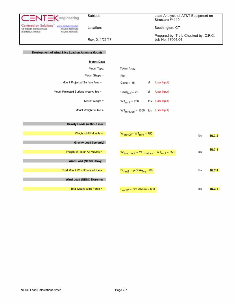
Subject:
Location:
Rev. 0: 1/26/17
Load Analysis of AT&T Equipment onStructure #4119
Southington, CT
Prepared by: T.J.L Checked by: C.F.C.Job No. 17004.04
Development of Wind & Ice Load on Antenna Mounts
Mount Data:
Mount Type: T-Arm Array
Mount Shape = Flat
Mount Projected Surface Area = CdAa 15:= sf (User Input)
Mount Projected Surface Area w/ Ice = CdAaice 20:= sf (User Input)
Mount Weight = WTmnt 750:= lbs (User Input)
Mount Weight w/ Ice = WTmnt.ice 1000:= lbs (User Input)
Gravity Loads (without ice)
Weight of All Mounts = Wtmnt2 WTmnt 750=:=lbs BLC 2
Gravity Load (ice only)
BLC 3Weight of Ice on All Mounts = Wtice.mnt2 WTmnt.ice WTmnt- 250=:= lbs
Wind Load (NESC Heavy)
Total Mount Wind Force w/ Ice = Fimnt2 p CdAaice× 80=:= lbs BLC 4
Wind Load (NESC Extreme)
Total Mount Wind Force = Fmnt2 qz CdAa× m× 633=:= lbs BLC 5
NESC Load Calculations.xmcd Page 7-7

Subject:
Location:
Rev. 0: 1/26/17
Load Analysis of AT&T Equipment onStructure #4119
Southington, CT
Prepared by: T.J.L Checked by: C.F.C.Job No. 17004.04
Development of Wind & Ice Load on Coax Cables
Coax Cable Data:
Coax Type = HELIAX 1-5/8"
Shape = Round (User Input)
Coax Outside Diameter = Dcoax 1.98:= in (User Input)
Coax Cable Length = Lcoax 10:= ft (User Input)
Weight of Coax per foot = Wtcoax 1.04:= plf (User Input)
Total Number of Coax = Ncoax 18:= (User Input)
No. of Coax Projecting Outside Face of Mast = NPcoax 6:= (User Input)
Wind Load (NESC Extreme)
Coax projected surface area = AcoaxNPcoaxDcoax( )
121=:= ft
Total Coax Wind Force (Above NU Structure) = Fcoax qz Cdcoax× Acoax× m× 61=:=plf BLC 5
Wind Load (NESC Heavy)
Coax projected surface area w/ Ice = AICEcoaxNPcoax Dcoax× 2 Ir×+( )
121.1=:= ft
Total Coax Wind Force w/ Ice = Ficoax p Cdcoax× AICEcoax× 6=:= plf BLC 4
Gravity Loads (without ice)
Weight of all cables w/o ice WTcoax Wtcoax Ncoax× 19=:= plf BLC 2
Gravity Load (ice only)
Ice Area per Linear Foot = Aicoaxπ4
Dcoax 2 Ir×+( )2 Dcoax2
-éë
ùû 3.9=:= sq in
Ice Weight All Coax per foot = WTicoax Ncoax Id×Aicoax
144× 27=:= plf BLC 3
NESC Load Calculations.xmcd Page 7-8

Subject:
Location:Date: 1/26/17 Prepared by: T.J.L. Checked by: C.F.C. Job No. 17004.04
12345
Footnotes:
Weight of Ice OnlyNESC Heavy Wind
NESC Extreme Wind
Weight of Appurtenances
Load Case
63-2 North Branford Road Tabulated Load CasesBranford, CT 06405 Southington, CT
Self Weight (Mast)
CENTEK engineering, INC. Analysis of NESC Heavy Wind and NESC Extreme WindConsulting Engineers for Obtaining Reactions Applied to Utility Pole
Ph. 203-488-0580 / Fax. 203-488-8587
Description
Load Cases and Combinations 8-0 NESC Load Cases

Subject: Analysis of NESC Heavy Wind and NESC Extreme Windfor Obtaining Reactions Applied to Utility PoleLoad Combinations Table
Location:Date: 1/26/17 Prepared by: T.J.L. Checked by: C.F.C. Job No. 17004.04
Envelope WindDescription Soultion Factor P-Delta BLC Factor BLC Factor BLC Factor BLC Factor BLC Factor
1 NESC Heavy Wind 1 1 1.5 2 1.5 3 1.5 4 2.5
2 NESC Extreme Wind 1 1 1 2 1 5 1
Footnotes:(1) BLC = Basic Load Case
Ph. 203-488-0580 / Fax. 203-488-8587
Load Combination
CENTEK engineering, INC.Consulting Engineers63-2 North Branford Road
Branford, CT 06405 Southington, CT
Load Cases and Combinations 8-1 NESC Load Combinations

Company : CENTEK Engineering, Inc. Jan 26, 2017Designer : tjl, cfcJob Number : 17004.04/AT&T CT1109 Checked By:_____Model Name : Structure #4119 Mast
GlobalDisplay Sections for Member CalcsMax Internal Sections for Member CalcsInclude Shear Deformation?Include Warping?Trans Load Btwn Intersecting Wood Wall?Increase Nailing Capacity for Wind?Area Load Mesh (in^2)Merge Tolerance (in)P-Delta Analysis ToleranceInclude P-Delta for Walls?Automaticly Iterate Stiffness for Walls?Maximum Iteration Number for Wall StiffnessGravity Acceleration (ft/sec^2)Wall Mesh Size (in)Eigensolution Convergence Tol. (1.E-)Vertical AxisGlobal Member Orientation PlaneStatic SolverDynamic Solver
597YesYesYesYes144.120.50%YesNo332.2124YXZSparse AcceleratedAccelerated Solver
Hot Rolled Steel CodeRISAConnection CodeCold Formed Steel CodeWood CodeWood TemperatureConcrete CodeMasonry CodeAluminum Code
AISC 9th: ASDAISC 14th(360-10): ASDAISI 1999: ASDAF&PA NDS-97: ASD< 100FACI 318-02ACI 530-05: ASDAA ADM1-05: ASD - Building
Number of Shear RegionsRegion Spacing Increment (in)Biaxial Column MethodParme Beta Factor (PCA)Concrete Stress BlockUse Cracked Sections?Use Cracked Sections Slab?Bad Framing Warnings?Unused Force Warnings?Min 1 Bar Diam. Spacing?Concrete Rebar SetMin % Steel for ColumnMax % Steel for Column
44PCA Load Contour.65RectangularYesYesNoYesNoREBAR_SET_ASTMA61518
RISA-3D Version 12.0.0 Page 1 [J:\...\...\...\04_Structural\Backup Documentation\Calcs\Risa-3D\NESC.r3d]

Company : CENTEK Engineering, Inc. Jan 26, 2017Designer : tjl, cfcJob Number : 17004.04/AT&T CT1109 Checked By:_____Model Name : Structure #4119 Mast
Global, ContinuedSeismic CodeSeismic Base Elevation (ft)Add Base Weight?Ct ZCt XT Z (sec)T X (sec)R ZR XCaCvNvOccupancy CategorySeismic Zone
UBC 1997Not EnteredNo.035.035Not EnteredNot Entered8.58.5.36.54143
Seismic Detailing CodeOm ZOm XRho ZRho X
ASCE 7-051111
Footing Overturning Safety FactorCheck Concrete BearingFooting Concrete Weight (k/ft^3)Footing Concrete f'c (ksi)Footing Concrete Ec (ksi)LamdaFooting Steel fy (ksi)Minimum SteelMaximum SteelFooting Top BarFooting Top Bar Cover (in)Footing Bottom BarFooting Bottom Bar Cover (in)Pedestal BarPedestal Bar Cover (in)Pedestal Ties
1.5No0340001600.00180.0075#33.5#33.5#31.5#3
Hot Rolled Steel PropertiesLabel E [ksi] G [ksi] Nu Therm (\1... Density[k/ft^3] Yield[ksi] Ry Fu[ksi] Rt
1 A36 Gr.36 29000 11154 .3 .65 .49 36 1.5 58 1.22 A572 Gr.50 29000 11154 .3 .65 .49 50 1.1 58 1.23 A992 29000 11154 .3 .65 .49 50 1.1 58 1.24 A500 Gr.42 29000 11154 .3 .65 .49 42 1.3 58 1.15 A500 Gr.46 29000 11154 .3 .65 .49 46 1.2 58 1.16 A53 Gr. B 29000 11154 .3 .65 .49 35 1.5 58 1.2
RISA-3D Version 12.0.0 Page 2 [J:\...\...\...\04_Structural\Backup Documentation\Calcs\Risa-3D\NESC.r3d]

Company : CENTEK Engineering, Inc. Jan 26, 2017Designer : tjl, cfcJob Number : 17004.04/AT&T CT1109 Checked By:_____Model Name : Structure #4119 Mast
Hot Rolled Steel Design ParametersLabel Shape Leng... Lbyy[ft] Lbzz[ft] Lcomp ...Lcomp ... Kyy Kzz Cm...Cm... Cb y s... z s... Functi...
1 M1 Mast 30 Lateral
Hot Rolled Steel Section SetsLabel Shape Type Design List Material Design ... A [in2] Iyy [in4] Izz [in4] J [in4]
1 Mast PIPE_12.0 Beam Pipe A53 Gr. B Typical 13.7 262 262 523
Member Primary DataLabel I Joint J Joint K Joint Rotate(d... Section/Shape Type Design List Material Design R...
1 M1 BOTCO...TOPMA... Mast Beam Pipe A53 Gr. B Typical
Joint Coordinates and TemperaturesLabel X [ft] Y [ft] Z [ft] Temp [F] Detach From ...
1 BOTCONNECTION 0 0 0 02 TOPCONNECTION 0 18 0 03 TOPMAST 0 30 0 0
Joint Boundary ConditionsJoint Label X [k/in] Y [k/in] Z [k/in] X Rot.[k-ft/rad] Y Rot.[k-ft/rad] Z Rot.[k-ft/rad] Footing
1 BOTCONNECTION Reaction Reaction Reaction Fixed2 TOPCONNECTION Reaction Reaction
Member Point Loads (BLC 2 : Weight of Appurtenances)Member Label Direction Magnitude[k,k-ft] Location[ft,%]
1 M1 Y -.146 302 M1 Y -.333 303 M1 Y -.058 304 M1 Y -.053 305 M1 Y -.75 30
Member Point Loads (BLC 3 : Weight of Ice Only)Member Label Direction Magnitude[k,k-ft] Location[ft,%]
1 M1 Y -.139 302 M1 Y -.172 303 M1 Y -.029 304 M1 Y -.02 305 M1 Y -.25 30
Member Point Loads (BLC 4 : NESC Heavy Wind)Member Label Direction Magnitude[k,k-ft] Location[ft,%]
1 M1 X .125 302 M1 X .127 303 M1 X .025 304 M1 X .016 30
RISA-3D Version 12.0.0 Page 3 [J:\...\...\...\04_Structural\Backup Documentation\Calcs\Risa-3D\NESC.r3d]

Company : CENTEK Engineering, Inc. Jan 26, 2017Designer : tjl, cfcJob Number : 17004.04/AT&T CT1109 Checked By:_____Model Name : Structure #4119 Mast
Member Point Loads (BLC 4 : NESC Heavy Wind) (Continued)Member Label Direction Magnitude[k,k-ft] Location[ft,%]
5 M1 X .08 30
Member Point Loads (BLC 5 : NESC Extreme Wind)Member Label Direction Magnitude[k,k-ft] Location[ft,%]
1 M1 X 1.195 302 M1 X 1.215 303 M1 X .23 304 M1 X .141 305 M1 X .633 30
Joint Loads and Enforced DisplacementsJoint Label L,D,M Direction Magnitude[(k,k-ft), (in,rad), (k*s^2/ft, k*s^2*ft)]
No Data to Print ...
Member Distributed Loads (BLC 2 : Weight of Appurtenances)Member Label Direction Start Magnitude[k/ft,F] End Magnitude[k/ft,F] Start Location[ft,%] End Location[ft,%]
1 M1 Y -.019 -.019 20 30
Member Distributed Loads (BLC 3 : Weight of Ice Only)Member Label Direction Start Magnitude[k/ft,F] End Magnitude[k/ft,F] Start Location[ft,%] End Location[ft,%]
1 M1 Y -.008 -.008 0 02 M1 Y -.027 -.027 20 30
Member Distributed Loads (BLC 4 : NESC Heavy Wind)Member Label Direction Start Magnitude[k/ft,F] End Magnitude[k/ft,F] Start Location[ft,%] End Location[ft,%]
1 M1 X .006 .006 0 02 M1 X .006 .006 20 30
Member Distributed Loads (BLC 5 : NESC Extreme Wind)Member Label Direction Start Magnitude[k/ft,F] End Magnitude[k/ft,F] Start Location[ft,%] End Location[ft,%]
1 M1 X .047 .047 0 202 M1 X .058 .058 20 303 M1 X .061 .061 20 30
Basic Load CasesBLC Description Category X Gra... Y Gravity Z Gra... Joint Point Distrib...Area(... Surfa...
1 Self Weight None -12 Weight of Appurtenances None 5 13 Weight of Ice Only None 5 24 NESC Heavy Wind None 5 25 NESC Extreme Wind None 5 3
RISA-3D Version 12.0.0 Page 4 [J:\...\...\...\04_Structural\Backup Documentation\Calcs\Risa-3D\NESC.r3d]

Company : CENTEK Engineering, Inc. Jan 26, 2017Designer : tjl, cfcJob Number : 17004.04/AT&T CT1109 Checked By:_____Model Name : Structure #4119 Mast
Load CombinationsDescription Sol... PDelta SR...BLC Fact...BLC Fact...BLC Fact...BLC Fact...BLC Fact...BLC Fact...BLC Fact...BLC Fact...
1 NESC Heavy Wind Yes 1 1.5 2 1.5 3 1.5 4 2.52 NESC Extreme Wind Yes 1 1 2 1 5 1
Envelope Joint ReactionsJoint X [k] LC Y [k] LC Z [k] LC MX [k-ft] LC MY [k-ft] LC MZ [k-ft] LC
1 BOTCONNE... max 2.321 2 6.073 1 0 1 0 1 NC NC 0 12 min .605 1 2.929 2 0 1 0 1 NC NC 0 13 TOPCONNE... max -2.137 1 0 1 0 1 0 1 0 1 0 14 min -7.865 2 0 1 0 1 0 1 0 1 0 15 Totals: max -1.532 1 6.073 1 0 16 min -5.544 2 2.929 2 0 1
RISA-3D Version 12.0.0 Page 5 [J:\...\...\...\04_Structural\Backup Documentation\Calcs\Risa-3D\NESC.r3d]

Company : CENTEK Engineering, Inc. Jan 26, 2017Designer : tjl, cfcJob Number : 17004.04/AT&T CT1109 Checked By:_____Model Name : Structure #4119 Mast
Joint ReactionsLC Joint Label X [k] Y [k] Z [k] MX [k-ft] MY [k-ft] MZ [k-ft]
1 1 BOTCONNECTION .605 6.073 0 0 NC 02 1 TOPCONNECTION -2.137 0 0 0 0 03 1 Totals: -1.532 6.073 04 1 COG (ft): X: 0 Y: 23.361 Z: 0
RISA-3D Version 12.0.0 Page 6 [J:\...\...\...\04_Structural\Backup Documentation\Calcs\Risa-3D\NESC.r3d]

Company : CENTEK Engineering, Inc. Jan 26, 2017Designer : tjl, cfcJob Number : 17004.04/AT&T CT1109 Checked By:_____Model Name : Structure #4119 Mast
Joint ReactionsLC Joint Label X [k] Y [k] Z [k] MX [k-ft] MY [k-ft] MZ [k-ft]
1 2 BOTCONNECTION 2.321 2.929 0 0 NC 02 2 TOPCONNECTION -7.865 0 0 0 0 03 2 Totals: -5.544 2.929 04 2 COG (ft): X: 0 Y: 22.512 Z: 0
RISA-3D Version 12.0.0 Page 7 [J:\...\...\...\04_Structural\Backup Documentation\Calcs\Risa-3D\NESC.r3d]

CENTEK Engineering, Inc.tjl, cfc
17004.04/AT&T CT1109
Structure #4119 Mast
LC #1 Loads
Jan 26, 2017 at 12:56 PMNESC.r3d
BOTCONNECTION
TOPCONNECTION
TOPMAST
-2.925k
.933k
-.069k/ft
-.012k/ft.015k/ft
.015k/ft
Y
XZ
Loads: LC 1, NESC Heavy Wind

CENTEK Engineering, Inc.tjl, cfc
17004.04/AT&T CT1109
Structure #4119 Mast
LC #1 Reactions
Jan 26, 2017 at 12:57 PMNESC.r3d
BOTCONNECTION
TOPCONNECTION
TOPMAST
0.6
6.1
-2.1
Y
XZ
Results for LC 1, NESC Heavy WindZ-direction Reaction Units are k and k-ft

CENTEK Engineering, Inc.tjl, cfc
17004.04/AT&T CT1109
Structure #4119 Mast
LC #2 Loads
Jan 26, 2017 at 12:56 PMNESC.r3d
BOTCONNECTION
TOPCONNECTION
TOPMAST
-1.34k
3.414k
-.019k/ft
.047k/ft
.119k/ft
Y
XZ
Loads: LC 2, NESC Extreme Wind

CENTEK Engineering, Inc.tjl, cfc
17004.04/AT&T CT1109
Structure #4119 Mast
LC #2 Reactions
Jan 26, 2017 at 1:00 PMNESC.r3d
BOTCONNECTION
TOPCONNECTION
TOPMAST
2.3
2.9
-7.9
Y
XZ
Results for LC 2, NESC Extreme WindZ-direction Reaction Units are k and k-ft

Subject:
Location:
Rev. 0: 1/26/17
Coax Cable on Tower # 4119
Southington, CT
Prepared by: T.J.L Checked by: C.F.C.Job No. 17004.04
Coax Cable on CL&P Tower SouthEast Leg
Distance Between Coax Cable Attach Points =
Coaxial Cable Span =CoaxSpan
2.5
5.5
6
5.5
5
5
5.5
6.25
10.5
29.75
æçççççççççççççè
ö÷÷÷÷÷÷÷÷÷÷÷÷÷ø
ft×:= (User Input)
Diameter of Coax Cable = Dcoax 1.98 in×:= (User Input)
Weight of Coax Cable = Wcoax 1.04 plf×:= (User Input)
Number of Coax Cables = Ncoax 12:= (User Input)
Number of Projected Coax Cables = NPcoax 6:= (User Input)
Extreme Wind Pressure = qz 33.8 psf×:= (User Input)
Heavy Wind Pressure = p 4 psf×:= (User Input)
Radial Ice Thickness = Ir 0.5 in×:= (User Input)
Radial Ice Density = Id 56 pcf×:= (User Input)
Shape Factor = Cdcoax 1.6:= (User Input)
Overload Factor for NESC Heavy Wind Load = OFHW 2.5:=(User Input)
Overload Factor for NESC Extreme Wind Load = OFEW 1.0:=(User Input)
Overload Factor for NESC Heavy Vertical Load = OFHV 1.5:=(User Input)
Overload Factor for NESC Extreme Vertical Load = OFEV 1.0:=(User Input)
Wind Area with Ice = Aice NPcoax Dcoax× 2 Ir×+( ) 12.88 in×=:=
Wind Area wit hout I ce = A NPcoax Dcoax×( ) 11.88 in×=:=
Ice Area per Liner Ft = Aicoaxπ4
Dcoax 2 Ir×+( )2Dcoax
2-é
ëùû× 0.027ft
2=:=
Weight of Ice on All Coax Cables = Wice Aicoax Id× Ncoax× 18.179 plf×=:=
Coax Cable on Tower.xmcd.xmcd Page 9.0-1

Subject:
Location:
Rev. 0: 1/26/17
Coax Cable on Tower # 4119
Southington, CT
Prepared by: T.J.L Checked by: C.F.C.Job No. 17004.04
Heavy Vertical Load =
HeavyVert Ncoax Wcoax× Wice+( ) CoaxSpan× OFHV×éë ùû®¾¾¾¾¾¾¾¾¾¾¾¾¾¾¾¾¾¾¾
:=
Heavy Transverse Load =
HeavyTrans p Aice× Cdcoax× CoaxSpan× OFHW×( )®¾¾¾¾¾¾¾¾¾¾¾¾¾¾¾
:=HeavyVert
00123456789
115253276253230230253287483
1368
lb= HeavyTrans
00123456789
4394
10394868694
107180511
lb=
Extreme Vertical Load =
ExtremeVert Ncoax Wcoax×( ) CoaxSpan× OFEV×éë ùû®¾¾¾¾¾¾¾¾¾¾¾¾¾¾¾
:=
Extreme Transverse Load =
ExtremeTrans qz A× Cdcoax×( ) CoaxSpan× OFEW×éë ùû®¾¾¾¾¾¾¾¾¾¾¾¾¾¾¾
:=ExtremeVert
00123456789
3169756962626978
131371
lb= ExtremeTrans
00123456789
134294321294268268294335562
1593
lb=
Coax Cable on Tower.xmcd.xmcd Page 9.0-2

Subject:
Location:
Rev. 0: 1/26/17
Coax Cable on Tower # 4119
Southington, CT
Prepared by: T.J.L Checked by: C.F.C.Job No. 17004.04
Coax Cable on CL&P Tower SouthWest Leg
Distance Between Coax Cable Attach Points =
Coaxial Cable Span =CoaxSpan
2.5
5.5
6
5.5
5
5
5.5
6.25
10.5
29.75
æçççççççççççççè
ö÷÷÷÷÷÷÷÷÷÷÷÷÷ø
ft×:= (User Input)
Diameter of Coax Cable = Dcoax 1.98 in×:= (User Input)
Weight of Coax Cable = Wcoax 1.04 plf×:= (User Input)
Number of Coax Cables = Ncoax 6:= (User Input)
Number of Projected Coax Cables = NPcoax 3:= (User Input)
Extreme Wind Pressure = qz 33.8 psf×:= (User Input)
Heavy Wind Pressure = p 4 psf×:= (User Input)
Radial Ice Thickness = Ir 0.5 in×:= (User Input)
Radial Ice Density = Id 56 pcf×:= (User Input)
Shape Factor = Cdcoax 1.6:= (User Input)
Overload Factor for NESC Heavy Wind Load = OFHW 2.5:=(User Input)
Overload Factor for NESC Extreme Wind Load = OFEW 1.0:=(User Input)
Overload Factor for NESC Heavy Vertical Load = OFHV 1.5:=(User Input)
Overload Factor for NESC Extreme Vertical Load = OFEV 1.0:=(User Input)
Wind Area with Ice = Aice NPcoax Dcoax× 2 Ir×+( ) 6.94 in×=:=
Wind Area wit hout I ce = A NPcoax Dcoax×( ) 5.94 in×=:=
Ice Area per Liner Ft = Aicoaxπ4
Dcoax 2 Ir×+( )2Dcoax
2-é
ëùû× 0.027ft
2=:=
Weight of Ice on All Coax Cables = Wice Aicoax Id× Ncoax× 9.09 plf×=:=
Coax Cable on Tower.xmcd.xmcd Page 9.0-3

Subject:
Location:
Rev. 0: 1/26/17
Coax Cable on Tower # 4119
Southington, CT
Prepared by: T.J.L Checked by: C.F.C.Job No. 17004.04
Heavy Vertical Load =
HeavyVert Ncoax Wcoax× Wice+( ) CoaxSpan× OFHV×éë ùû®¾¾¾¾¾¾¾¾¾¾¾¾¾¾¾¾¾¾¾
:=
Heavy Transverse Load =
HeavyTrans p Aice× Cdcoax× CoaxSpan× OFHW×( )®¾¾¾¾¾¾¾¾¾¾¾¾¾¾¾
:=HeavyVert
00123456789
57126138126115115126144241684
lb= HeavyTrans
00123456789
235156514646515897
275
lb=
Extreme Vertical Load =
ExtremeVert Ncoax Wcoax×( ) CoaxSpan× OFEV×éë ùû®¾¾¾¾¾¾¾¾¾¾¾¾¾¾¾
:=
Extreme Transverse Load =
ExtremeTrans qz A× Cdcoax×( ) CoaxSpan× OFEW×éë ùû®¾¾¾¾¾¾¾¾¾¾¾¾¾¾¾
:=ExtremeVert
00123456789
163437343131343966
186
lb= ExtremeTrans
00123456789
67147161147134134147167281796
lb=
Coax Cable on Tower.xmcd.xmcd Page 9.0-4

1P
2P
3P
4P
5P
6P
7P
12P
13P
14P
15P
1X1XY 1Y
2X2XY 2Y
3X3XY 3Y
4X4XY 4Y
5X5XY 5Y
6X6XY 6Y
7X
7XY
7Y
12X
13X
14X
15X
8S
9S
10S
11S
16S
1XYF0.50S
4XYF0.50S
8X8XY
8Y
9X
9XY9Y
10X
10XY10Y
11X
11XY11Y
16X16XY16Y
X Y
Z
Centek Engineering Inc, Project: "cl&p # 4119"Tower Version 12.50, 2:24:51 PM Thursday, January 26, 2017Undeformed geometry displayed

Centek Engineering Inc - cl&p # 4119 Page 1/7
Project Name : 17004.04 - Southington, CTProject Notes: Structure #4119 / AT&T CT1109Project File : J:\Jobs\1700400.WI\04_Southington-Cathydrive NU CT1109\04_Structural\Backup Documentation\Calcs\PLS Tower\cl&p # 4119.towDate run : 3:27:25 PM Thursday, January 26, 2017by : Tower Version 12.50Licensed to : Centek Engineering Inc
Successfully performed nonlinear analysis
Member "g14P" will not be checked for block shear since more than one gage line exists (long edge distance (g) greater than zero); however, end, edgeand spacing distances will be checked. ??Member "g14X" will not be checked for block shear since more than one gage line exists (long edge distance (g) greater than zero); however, end, edgeand spacing distances will be checked. ??Member "g14XY" will not be checked for block shear since more than one gage line exists (long edge distance (g) greater than zero); however, end, edgeand spacing distances will be checked. ??Member "g14Y" will not be checked for block shear since more than one gage line exists (long edge distance (g) greater than zero); however, end, edgeand spacing distances will be checked. ??Member "g17P" will not be checked for block shear since more than one gage line exists (long edge distance (g) greater than zero); however, end, edgeand spacing distances will be checked. ??Member "g17X" will not be checked for block shear since more than one gage line exists (long edge distance (g) greater than zero); however, end, edgeand spacing distances will be checked. ??Member "g17XY" will not be checked for block shear since more than one gage line exists (long edge distance (g) greater than zero); however, end, edgeand spacing distances will be checked. ??Member "g17Y" will not be checked for block shear since more than one gage line exists (long edge distance (g) greater than zero); however, end, edgeand spacing distances will be checked. ??Member "g18P" will not be checked for block shear since more than one gage line exists (long edge distance (g) greater than zero); however, end, edgeand spacing distances will be checked. ??Member "g18X" will not be checked for block shear since more than one gage line exists (long edge distance (g) greater than zero); however, end, edgeand spacing distances will be checked. ??Member "g18XY" will not be checked for block shear since more than one gage line exists (long edge distance (g) greater than zero); however, end, edgeand spacing distances will be checked. ??Member "g18Y" will not be checked for block shear since more than one gage line exists (long edge distance (g) greater than zero); however, end, edgeand spacing distances will be checked. ??Member "g19P" will not be checked for block shear since more than one gage line exists (long edge distance (g) greater than zero); however, end, edgeand spacing distances will be checked. ??Member "g19X" will not be checked for block shear since more than one gage line exists (long edge distance (g) greater than zero); however, end, edgeand spacing distances will be checked. ??Member "g19XY" will not be checked for block shear since more than one gage line exists (long edge distance (g) greater than zero); however, end, edgeand spacing distances will be checked. ??Member "g19Y" will not be checked for block shear since more than one gage line exists (long edge distance (g) greater than zero); however, end, edgeand spacing distances will be checked. ??Member "g22P" will not be checked for block shear since more than one gage line exists (long edge distance (g) greater than zero); however, end, edgeand spacing distances will be checked. ??Member "g22X" will not be checked for block shear since more than one gage line exists (long edge distance (g) greater than zero); however, end, edgeand spacing distances will be checked. ??Member "g22XY" will not be checked for block shear since more than one gage line exists (long edge distance (g) greater than zero); however, end, edgeand spacing distances will be checked. ??Member "g22Y" will not be checked for block shear since more than one gage line exists (long edge distance (g) greater than zero); however, end, edgeand spacing distances will be checked. ??Member "g23P" will not be checked for block shear since more than one gage line exists (long edge distance (g) greater than zero); however, end, edgeand spacing distances will be checked. ??Member "g23X" will not be checked for block shear since more than one gage line exists (long edge distance (g) greater than zero); however, end, edgeand spacing distances will be checked. ??Member "g23XY" will not be checked for block shear since more than one gage line exists (long edge distance (g) greater than zero); however, end, edgeand spacing distances will be checked. ??Member "g23Y" will not be checked for block shear since more than one gage line exists (long edge distance (g) greater than zero); however, end, edgeand spacing distances will be checked. ??Member "g24P" will not be checked for block shear since more than one gage line exists (long edge distance (g) greater than zero); however, end, edge

Centek Engineering Inc - cl&p # 4119 Page 2/7
and spacing distances will be checked. ??Member "g24X" will not be checked for block shear since more than one gage line exists (long edge distance (g) greater than zero); however, end, edgeand spacing distances will be checked. ??Member "g24XY" will not be checked for block shear since more than one gage line exists (long edge distance (g) greater than zero); however, end, edgeand spacing distances will be checked. ??Member "g24Y" will not be checked for block shear since more than one gage line exists (long edge distance (g) greater than zero); however, end, edgeand spacing distances will be checked. ??Member "g25P" will not be checked for block shear since more than one gage line exists (long edge distance (g) greater than zero); however, end, edgeand spacing distances will be checked. ??Member "g25X" will not be checked for block shear since more than one gage line exists (long edge distance (g) greater than zero); however, end, edgeand spacing distances will be checked. ??Member "g25XY" will not be checked for block shear since more than one gage line exists (long edge distance (g) greater than zero); however, end, edgeand spacing distances will be checked. ??Member "g25Y" will not be checked for block shear since more than one gage line exists (long edge distance (g) greater than zero); however, end, edgeand spacing distances will be checked. ??Member "g26P" will not be checked for block shear since more than one gage line exists (long edge distance (g) greater than zero); however, end, edgeand spacing distances will be checked. ??Member "g26X" will not be checked for block shear since more than one gage line exists (long edge distance (g) greater than zero); however, end, edgeand spacing distances will be checked. ??Member "g26XY" will not be checked for block shear since more than one gage line exists (long edge distance (g) greater than zero); however, end, edgeand spacing distances will be checked. ??Member "g26Y" will not be checked for block shear since more than one gage line exists (long edge distance (g) greater than zero); however, end, edgeand spacing distances will be checked. ??Member "g27P" will not be checked for block shear since more than one gage line exists (long edge distance (g) greater than zero); however, end, edgeand spacing distances will be checked. ??Member "g27X" will not be checked for block shear since more than one gage line exists (long edge distance (g) greater than zero); however, end, edgeand spacing distances will be checked. ??Member "g27XY" will not be checked for block shear since more than one gage line exists (long edge distance (g) greater than zero); however, end, edgeand spacing distances will be checked. ??Member "g27Y" will not be checked for block shear since more than one gage line exists (long edge distance (g) greater than zero); however, end, edgeand spacing distances will be checked. ??Member "g28P" will not be checked for block shear since more than one gage line exists (long edge distance (g) greater than zero); however, end, edgeand spacing distances will be checked. ??Member "g28X" will not be checked for block shear since more than one gage line exists (long edge distance (g) greater than zero); however, end, edgeand spacing distances will be checked. ??Member "g28XY" will not be checked for block shear since more than one gage line exists (long edge distance (g) greater than zero); however, end, edgeand spacing distances will be checked. ??Member "g28Y" will not be checked for block shear since more than one gage line exists (long edge distance (g) greater than zero); however, end, edgeand spacing distances will be checked. ??Member "g29P" will not be checked for block shear since more than one gage line exists (long edge distance (g) greater than zero); however, end, edgeand spacing distances will be checked. ??Member "g29X" will not be checked for block shear since more than one gage line exists (long edge distance (g) greater than zero); however, end, edgeand spacing distances will be checked. ??Member "g29XY" will not be checked for block shear since more than one gage line exists (long edge distance (g) greater than zero); however, end, edgeand spacing distances will be checked. ??Member "g29Y" will not be checked for block shear since more than one gage line exists (long edge distance (g) greater than zero); however, end, edgeand spacing distances will be checked. ??Member "g32P" will not be checked for block shear since more than one gage line exists (long edge distance (g) greater than zero); however, end, edgeand spacing distances will be checked. ??Member "g32X" will not be checked for block shear since more than one gage line exists (long edge distance (g) greater than zero); however, end, edgeand spacing distances will be checked. ??Member "g32XY" will not be checked for block shear since more than one gage line exists (long edge distance (g) greater than zero); however, end, edgeand spacing distances will be checked. ??Member "g32Y" will not be checked for block shear since more than one gage line exists (long edge distance (g) greater than zero); however, end, edgeand spacing distances will be checked. ??Member "g33P" will not be checked for block shear since more than one gage line exists (long edge distance (g) greater than zero); however, end, edgeand spacing distances will be checked. ??Member "g33X" will not be checked for block shear since more than one gage line exists (long edge distance (g) greater than zero); however, end, edge

Centek Engineering Inc - cl&p # 4119 Page 3/7
and spacing distances will be checked. ??Member "g33XY" will not be checked for block shear since more than one gage line exists (long edge distance (g) greater than zero); however, end, edgeand spacing distances will be checked. ??Member "g33Y" will not be checked for block shear since more than one gage line exists (long edge distance (g) greater than zero); however, end, edgeand spacing distances will be checked. ??Member "g34P" will not be checked for block shear since more than one gage line exists (long edge distance (g) greater than zero); however, end, edgeand spacing distances will be checked. ??Member "g34X" will not be checked for block shear since more than one gage line exists (long edge distance (g) greater than zero); however, end, edgeand spacing distances will be checked. ??Member "g34XY" will not be checked for block shear since more than one gage line exists (long edge distance (g) greater than zero); however, end, edgeand spacing distances will be checked. ??Member "g34Y" will not be checked for block shear since more than one gage line exists (long edge distance (g) greater than zero); however, end, edgeand spacing distances will be checked. ??Member "g35P" will not be checked for block shear since more than one gage line exists (long edge distance (g) greater than zero); however, end, edgeand spacing distances will be checked. ??Member "g35X" will not be checked for block shear since more than one gage line exists (long edge distance (g) greater than zero); however, end, edgeand spacing distances will be checked. ??Member "g35XY" will not be checked for block shear since more than one gage line exists (long edge distance (g) greater than zero); however, end, edgeand spacing distances will be checked. ??Member "g35Y" will not be checked for block shear since more than one gage line exists (long edge distance (g) greater than zero); however, end, edgeand spacing distances will be checked. ??The model has 64 warnings. ??
Member check option: ASCE 10Connection rupture check: ASCE 10Crossing diagonal check: ASCE 10 [Alternate Unsupported RLOUT = 1]Included angle check: NoneClimbing load check: NoneRedundant members checked with: Actual Force
Loads from file: j:\jobs\1700400.wi\04_southington-cathydrive nu ct1109\04_structural\backup documentation\calcs\pls tower\cl&p # 4119.lca
*** Analysis Results:
Maximum element usage is 81.86% for Angle "g17X" in load case "NESC Extreme"Maximum insulator usage is 16.01% for Clamp "19" in load case "NESC Extreme"
Summary of Joint Support Reactions For All Load Cases:
Load Case Joint Long. Tran. Vert. Shear Tran. Long. Bending Vert. Found. Label Force Force Force Force Moment Moment Moment Moment Usage (kips) (kips) (kips) (kips) (ft-k) (ft-k) (ft-k) (ft-k) %----------------------------------------------------------------------------------- NESC Heavy 7P -6.17 -4.92 -30.80 7.89 0.02 -0.01 0.02 0.00 0.00 NESC Heavy 7X 2.95 -2.31 15.43 3.75 0.02 -0.00 0.02 0.01 0.00 NESC Heavy 7XY -2.93 -2.55 14.21 3.88 0.05 -0.00 0.05 -0.00 0.00 NESC Heavy 7Y 6.15 -6.02 -33.69 8.61 0.04 -0.01 0.04 -0.00 0.00 NESC Extreme 7P -7.06 -8.19 -51.76 10.81 0.04 -0.15 0.15 0.02 0.00 NESC Extreme 7X 8.91 -6.73 44.85 11.17 0.03 0.01 0.04 0.04 0.00 NESC Extreme 7XY -9.01 -11.50 48.40 14.61 0.25 0.01 0.25 0.01 0.00 NESC Extreme 7Y 7.16 -8.08 -56.82 10.80 0.23 -0.17 0.28 -0.01 0.00
Summary of Joint Support Reactions For All Load Cases in Direction of Leg:
Load Case Support Origin Leg Force In Residual Shear Residual Shear Residual Shear Residual Shear Total Total Total Joint Joint Member Leg Dir. Perpendicular Horizontal Horizontal Horizontal Long. Tran. Vert. To Leg To Leg - Res. To Leg - Long. To Leg - Tran. Force Force Force (kips) (kips) (kips) (kips) (kips)(kips) (kips) (kips)----------------------------------------------------------------------------------------------------------------------------

Centek Engineering Inc - cl&p # 4119 Page 4/7
NESC Heavy 7P 11S g19X 31.731 2.018 2.049 1.933 0.678 -6.17 -4.92 -30.80 NESC Heavy 7X 11X g19P -15.862 0.834 0.845 -0.823 0.191 2.95 -2.31 15.43 NESC Heavy 7XY 11XY g19Y -14.689 1.116 1.136 0.970 0.592 -2.93 -2.55 14.21 NESC Heavy 7Y 11Y g19XY 34.711 2.013 2.051 -1.514 1.383 6.15 -6.02 -33.69 NESC Extreme 7P 11S g19X 52.862 1.058 1.067 -0.062 1.065 -7.06 -8.19 -51.76 NESC Extreme 7X 11X g19P -46.135 2.761 2.797 -2.740 0.562 8.91 -6.73 44.85 NESC Extreme 7XY 11XY g19Y -50.280 5.290 5.378 2.348 4.838 -9.01 -11.50 48.40 NESC Extreme 7Y 11Y g19XY 57.827 0.710 0.712 0.661 0.265 7.16 -8.08 -56.82
Overturning Moment Summary For All Load Cases:
Load Case Transverse Longitudinal Resultant Moment Moment Moment (ft-k) (ft-k) (ft-k)----------------------------------------------- NESC Heavy 941.345 -41.116 942.243 NESC Extreme 2018.192 -15.068 2018.248
Sections Information:
Section Top Bottom Joint Member Tran. Face Tran. Face Tran. Face Long. Face Long. Face Long. Face Label Z Z Count Count Top Width Bot Width Gross Area Top Width Bot Width Gross Area (ft) (ft) (ft) (ft) (ft^2) (ft) (ft) (ft^2)----------------------------------------------------------------------------------------------------- 1 81.500 37.000 50 162 5.00 9.82 264.644 27.50 9.82 431.144 2 37.000 0.000 12 28 9.82 20.00 551.606 9.82 20.00 551.606
*** Overall summary for all load cases - Usage = Maximum Stress / Allowable Stress Printed capacities do not include the strength factor entered for each load case. The Group Summary reports on the member and load case that resulted in maximum usage which may not necessarily be the same as that which produces maximum force.
Group Summary (Compression Portion):
Group Group Angle Angle Steel Max Usage Max Comp. Comp. Comp. L/R Comp. Comp. RLX RLY RLZ L/RKL/R Length Curve No. Label Desc. Type Size Strength Usage Cont- Use Control Force Control Capacity Connect. Connect.Comp. No. Of rol In Member Load Shear BearingMember Bolts Comp. Case Capacity CapacityComp. (ksi) % % (kips) (kips) (kips) (kips)(ft)------------------------------------------------------------------------------------------------------------------------------------------------------------------------------ LEG1 L4X4X1/4 SAE 4X4X0.25 33.0 71.03 Comp 71.03 g14XY -38.006NESC Ext 53.509 109.200 168.750 1.000 1.000 1.000 75.4775.47 5.000 1 12 A potentially damaging moment exists in the following members (make sure your system is well triangulated to minimizemoments): g4P g5P g6Y g12P g13P ?? LEG2 L4X4X5/16 SAE 4X4X0.3125 33.0 81.86 Comp 81.86 g17X -45.974NESC Ext 56.161 91.000 175.781 1.000 1.000 1.000 100.46100.46 6.622 1 10 LEG3 L4X4X3/8 SAE 4X4X0.375 33.0 69.00 Comp 69.00 g19XY -58.744NESC Ext 85.135 91.000 210.937 0.167 0.167 0.167 58.2958.29 22.922 1 10 XBR1 L1.75X1.75X3/16 SAE 1.75X1.75X0.1875 33.0 27.91 Comp 27.91 g20Y -3.227NESC Ext 11.559 18.200 21.094 0.750 0.500 0.500 123.69122.85 7.071 5 2 XBR2 L3X2X3/16 SAU 3X2X0.1875 33.0 44.84 Comp 44.84 g24Y -7.746NESC Ext 17.275 27.300 31.641 0.500 0.750 0.500 120.57120.47 7.810 5 3 XBR3 L2X2X3/16 SAE 2X2X0.1875 33.0 35.79 Cross 35.79 g31Y -3.866NESC Ext 10.802 18.200 21.094 1.000 0.559 0.559 147.90
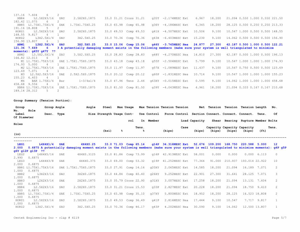
Centek Engineering Inc - cl&p # 4119 Page 5/7
137.16 7.604 6 2 XBR4 L2.5X2X3/16 SAU 2.5X2X0.1875 33.0 31.21 Cross 31.21 g35Y -2.174NESC Ext 6.967 18.200 21.094 0.550 1.000 0.550 221.50182.42 11.075 6 2 XBR5 L1.75X1.75X1/4 SAE 1.75X1.75X0.25 33.0 65.98 Comp 65.98 g36Y -4.186NESC Ext 6.345 18.200 28.125 0.500 0.250 0.250 213.33191.16 18.808 5 2 HORZ1 L2.5X2X3/16 SAU 2.5X2X0.1875 33.0 49.53 Comp 49.53 g41X -4.507NESC Ext 10.506 9.100 10.547 1.000 0.500 0.500 148.55148.55 9.817 4 1 HORZ2 L3X2.5X1/4 SAU 3X2.5X0.25 33.0 70.36 Comp 70.36 g43X -6.403NESC Ext 15.230 9.100 14.062 0.500 0.500 0.500 156.90156.90 13.807 4 1 ARM1 L3X2.5X1/4 SAU 3X2.5X0.25 33.0 15.06 Comp 15.06 g46Y -3.745NESC Hea 24.877 27.300 42.187 0.500 1.000 0.500 122.21121.36 7.669 6 3 A potentially damaging moment exists in the following members (make sure your system is well triangulated to minimizemoments): g45Y g47Y ?? ARM2 L3.5X2.5X1/4 SAU 3.5X2.5X0.25 33.0 28.83 Comp 28.83 g48Y -4.270NESC Hea 14.810 27.300 42.187 0.500 1.000 0.500 196.13166.82 12.013 6 3 M1 L1.75X1.75X3/16 SAE 1.75X1.75X0.1875 33.0 43.18 Comp 43.18 g55P -2.504NESC Ext 5.799 9.100 10.547 1.000 1.000 1.000 174.93174.93 5.000 4 1 M2 L1.75X1.75X3/16 SAE 1.75X1.75X0.1875 33.0 11.97 Comp 11.97 g57X -1.089NESC Ext 11.437 9.100 10.547 0.750 0.500 0.500 123.69123.69 7.071 4 1 M3 L2.5X2.5X3/16 SAE 2.5X2.5X0.1875 33.0 20.12 Comp 20.12 g60P -1.831NESC Hea 10.714 9.100 10.547 1.000 1.000 1.000 155.23155.23 6.403 4 1 M4 BAR 1.75X1/4 Bar 1-3/4x1/4 33.0 47.96 Tens 2.46 g63XY -0.015NESC Ext 0.595 9.100 14.062 1.000 1.000 1.000 458.68458.68 9.556 4 1 XBR6 L1.75X1.75X3/16 SAE 1.75X1.75X0.1875 33.0 81.50 Comp 81.50 g39Y -4.043NESC Hea 4.961 18.200 21.094 0.333 0.167 0.167 210.68189.14 28.312 5 2
Group Summary (Tension Portion):
Group Group Angle Angle Steel Max Usage Max Tension Tension Tension Net Tension Tension Tension Length No.No. Hole Label Desc. Type Size Strength Usage Cont- Use Control Force Control Section Connect. Connect. Connect. Tens. OfOf Diameter rol In Member Load Capacity Shear Bearing Rupture Member BoltsHoles Tens. Case Capacity Capacity Capacity Tens. (ksi) % % (kips) (kips) (kips) (kips) (kips) (ft)(in)---------------------------------------------------------------------------------------------------------------------------------------------------------------- LEG1 L4X4X1/4 SAE 4X4X0.25 33.0 71.03 Comp 65.14 g14P 34.316NESC Ext 52.676 109.200 168.750 220.588 5.000 122.000 0.6875 A potentially damaging moment exists in the following members (make sure your system is well triangulated to minimize moments): g4P g5Pg6Y g12P g13P ?? LEG2 L4X4X5/16 SAE 4X4X0.3125 33.0 81.86 Comp 73.99 g16P 42.913NESC Ext 58.001 0.000 0.000 0.000 6.113 02.990 0.6875 LEG3 L4X4X3/8 SAE 4X4X0.375 33.0 69.00 Comp 53.32 g19P 41.252NESC Ext 77.364 91.000 210.937 193.014 22.922 102.000 0.6875 XBR1 L1.75X1.75X3/16 SAE 1.75X1.75X0.1875 33.0 27.91 Comp 14.16 g20XY 2.065NESC Ext 14.585 18.200 21.094 16.189 7.071 21.000 0.6875 XBR2 L3X2X3/16 SAU 3X2X0.1875 33.0 44.84 Comp 40.40 g26XY 9.252NESC Ext 22.901 27.300 31.641 28.125 7.071 31.000 0.6875 XBR3 L2X2X3/16 SAE 2X2X0.1875 33.0 35.79 Cross 22.90 g31XY 3.007NESC Ext 17.258 18.200 21.094 13.131 7.604 21.000 0.6875 XBR4 L2.5X2X3/16 SAU 2.5X2X0.1875 33.0 31.21 Cross 15.53 g33P 2.827NESC Ext 20.228 18.200 21.094 18.750 9.410 21.000 0.6875 XBR5 L1.75X1.75X1/4 SAE 1.75X1.75X0.25 33.0 65.98 Comp 35.10 g37XY 5.800NESC Ext 18.952 18.200 28.125 16.523 18.808 21.000 0.6875 HORZ1 L2.5X2X3/16 SAU 2.5X2X0.1875 33.0 49.53 Comp 36.49 g41P 2.816NESC Hea 17.444 9.100 10.547 7.717 9.817 11.000 0.6875 HORZ2 L3X2.5X1/4 SAU 3X2.5X0.25 33.0 70.36 Comp 46.17 g43P 4.202NESC Hea 30.090 9.100 14.062 12.500 13.807 1

Centek Engineering Inc - cl&p # 4119 Page 6/7
1.000 0.6875 ARM1 L3X2.5X1/4 SAU 3X2.5X0.25 33.0 15.06 Comp 5.93 g45P 2.563NESC Hea 43.230 0.000 0.000 0.000 5.000 01.000 0 A potentially damaging moment exists in the following members (make sure your system is well triangulated to minimize moments): g45Yg47Y ?? ARM2 L3.5X2.5X1/4 SAU 3.5X2.5X0.25 33.0 28.83 Comp 0.00 g49Y 0.000 47.520 0.000 0.000 0.000 5.000 01.000 0 M1 L1.75X1.75X3/16 SAE 1.75X1.75X0.1875 33.0 43.18 Comp 36.83 g55X 2.842NESC Ext 14.585 9.100 10.547 7.717 5.000 11.000 0.6875 M2 L1.75X1.75X3/16 SAE 1.75X1.75X0.1875 33.0 11.97 Comp 9.12 g57P 0.704NESC Ext 14.585 9.100 10.547 7.717 7.071 11.000 0.6875 M3 L2.5X2.5X3/16 SAE 2.5X2.5X0.1875 33.0 20.12 Comp 0.00 g60X 0.000 22.961 9.100 10.547 9.375 6.403 11.000 0.6875 M4 BAR 1.75X1/4 Bar 1-3/4x1/4 33.0 47.96 Tens 47.96 g62Y 3.784NESC Hea 7.889 9.100 14.062 12.500 12.382 11.000 0.6875 XBR6 L1.75X1.75X3/16 SAE 1.75X1.75X0.1875 33.0 81.50 Comp 67.31 g38XY 8.886NESC Ext 14.585 18.200 21.094 13.201 28.312 21.000 0.6875
*** Maximum Stress Summary for Each Load Case
Summary of Maximum Usages by Load Case:
Load Case Maximum Element Element Usage % Label Type------------------------------------- NESC Heavy 81.50 g39Y Angle NESC Extreme 81.86 g17X Angle
Summary of Insulator Usages:
Insulator Insulator Maximum Load Case Weight Label Type Usage % (lbs)------------------------------------------------ 1 Clamp 3.53 NESC Heavy 0.0 2 Clamp 2.38 NESC Heavy 0.0 3 Clamp 4.32 NESC Heavy 0.0 4 Clamp 4.24 NESC Heavy 0.0 5 Clamp 4.34 NESC Heavy 0.0 6 Clamp 4.30 NESC Heavy 0.0 7 Clamp 4.28 NESC Heavy 0.0 8 Clamp 4.23 NESC Heavy 0.0 9 Clamp 0.59 NESC Extreme 0.0 10 Clamp 0.92 NESC Extreme 0.0 11 Clamp 0.98 NESC Extreme 0.0 12 Clamp 0.94 NESC Heavy 0.0 13 Clamp 0.87 NESC Extreme 0.0 14 Clamp 0.91 NESC Heavy 0.0 15 Clamp 0.92 NESC Extreme 0.0 16 Clamp 1.02 NESC Heavy 0.0 17 Clamp 2.34 NESC Extreme 0.0 18 Clamp 4.29 NESC Heavy 0.0 19 Clamp 16.01 NESC Extreme 0.0 20 Clamp 12.25 NESC Heavy 0.0 21 Clamp 0.46 NESC Extreme 0.0 22 Clamp 0.62 NESC Extreme 0.0

Centek Engineering Inc - cl&p # 4119 Page 7/7
23 Clamp 0.65 NESC Extreme 0.0 24 Clamp 0.64 NESC Heavy 0.0 25 Clamp 0.59 NESC Extreme 0.0 26 Clamp 0.60 NESC Heavy 0.0 27 Clamp 0.62 NESC Extreme 0.0 28 Clamp 0.66 NESC Extreme 0.0 29 Clamp 1.78 NESC Extreme 0.0 30 Clamp 2.61 NESC Heavy 0.0
*** Weight of structure (lbs): Weight of Angles*Section DLF: 7165.3 Total: 7165.3
*** End of Report

Centek Engineering Inc - cl&p # 4119 Page 1/46
******************************************************************************** ** TOWER - Analysis and Design - Copyright Power Line Systems, Inc. 1986-2011 ** ********************************************************************************
Project Name : 17004.04 - Southington, CTProject Notes: Structure #4119 / AT&T CT1109Project File : J:\Jobs\1700400.WI\04_Southington-Cathydrive NU CT1109\04_Structural\Backup Documentation\Calcs\PLS Tower\cl&p # 4119.towDate run : 3:27:24 PM Thursday, January 26, 2017by : Tower Version 12.50Licensed to : Centek Engineering Inc
Successfully performed nonlinear analysis
Member "g14P" will not be checked for block shear since more than one gage line exists (long edge distance (g) greater than zero); however, end, edgeand spacing distances will be checked. ??Member "g14X" will not be checked for block shear since more than one gage line exists (long edge distance (g) greater than zero); however, end, edgeand spacing distances will be checked. ??Member "g14XY" will not be checked for block shear since more than one gage line exists (long edge distance (g) greater than zero); however, end, edgeand spacing distances will be checked. ??Member "g14Y" will not be checked for block shear since more than one gage line exists (long edge distance (g) greater than zero); however, end, edgeand spacing distances will be checked. ??Member "g17P" will not be checked for block shear since more than one gage line exists (long edge distance (g) greater than zero); however, end, edgeand spacing distances will be checked. ??Member "g17X" will not be checked for block shear since more than one gage line exists (long edge distance (g) greater than zero); however, end, edgeand spacing distances will be checked. ??Member "g17XY" will not be checked for block shear since more than one gage line exists (long edge distance (g) greater than zero); however, end, edgeand spacing distances will be checked. ??Member "g17Y" will not be checked for block shear since more than one gage line exists (long edge distance (g) greater than zero); however, end, edgeand spacing distances will be checked. ??Member "g18P" will not be checked for block shear since more than one gage line exists (long edge distance (g) greater than zero); however, end, edgeand spacing distances will be checked. ??Member "g18X" will not be checked for block shear since more than one gage line exists (long edge distance (g) greater than zero); however, end, edgeand spacing distances will be checked. ??Member "g18XY" will not be checked for block shear since more than one gage line exists (long edge distance (g) greater than zero); however, end, edgeand spacing distances will be checked. ??Member "g18Y" will not be checked for block shear since more than one gage line exists (long edge distance (g) greater than zero); however, end, edgeand spacing distances will be checked. ??Member "g19P" will not be checked for block shear since more than one gage line exists (long edge distance (g) greater than zero); however, end, edgeand spacing distances will be checked. ??Member "g19X" will not be checked for block shear since more than one gage line exists (long edge distance (g) greater than zero); however, end, edgeand spacing distances will be checked. ??Member "g19XY" will not be checked for block shear since more than one gage line exists (long edge distance (g) greater than zero); however, end, edgeand spacing distances will be checked. ??Member "g19Y" will not be checked for block shear since more than one gage line exists (long edge distance (g) greater than zero); however, end, edgeand spacing distances will be checked. ??Member "g22P" will not be checked for block shear since more than one gage line exists (long edge distance (g) greater than zero); however, end, edgeand spacing distances will be checked. ??Member "g22X" will not be checked for block shear since more than one gage line exists (long edge distance (g) greater than zero); however, end, edgeand spacing distances will be checked. ??Member "g22XY" will not be checked for block shear since more than one gage line exists (long edge distance (g) greater than zero); however, end, edgeand spacing distances will be checked. ??Member "g22Y" will not be checked for block shear since more than one gage line exists (long edge distance (g) greater than zero); however, end, edgeand spacing distances will be checked. ??Member "g23P" will not be checked for block shear since more than one gage line exists (long edge distance (g) greater than zero); however, end, edgeand spacing distances will be checked. ??Member "g23X" will not be checked for block shear since more than one gage line exists (long edge distance (g) greater than zero); however, end, edge

Centek Engineering Inc - cl&p # 4119 Page 2/46
and spacing distances will be checked. ??Member "g23XY" will not be checked for block shear since more than one gage line exists (long edge distance (g) greater than zero); however, end, edgeand spacing distances will be checked. ??Member "g23Y" will not be checked for block shear since more than one gage line exists (long edge distance (g) greater than zero); however, end, edgeand spacing distances will be checked. ??Member "g24P" will not be checked for block shear since more than one gage line exists (long edge distance (g) greater than zero); however, end, edgeand spacing distances will be checked. ??Member "g24X" will not be checked for block shear since more than one gage line exists (long edge distance (g) greater than zero); however, end, edgeand spacing distances will be checked. ??Member "g24XY" will not be checked for block shear since more than one gage line exists (long edge distance (g) greater than zero); however, end, edgeand spacing distances will be checked. ??Member "g24Y" will not be checked for block shear since more than one gage line exists (long edge distance (g) greater than zero); however, end, edgeand spacing distances will be checked. ??Member "g25P" will not be checked for block shear since more than one gage line exists (long edge distance (g) greater than zero); however, end, edgeand spacing distances will be checked. ??Member "g25X" will not be checked for block shear since more than one gage line exists (long edge distance (g) greater than zero); however, end, edgeand spacing distances will be checked. ??Member "g25XY" will not be checked for block shear since more than one gage line exists (long edge distance (g) greater than zero); however, end, edgeand spacing distances will be checked. ??Member "g25Y" will not be checked for block shear since more than one gage line exists (long edge distance (g) greater than zero); however, end, edgeand spacing distances will be checked. ??Member "g26P" will not be checked for block shear since more than one gage line exists (long edge distance (g) greater than zero); however, end, edgeand spacing distances will be checked. ??Member "g26X" will not be checked for block shear since more than one gage line exists (long edge distance (g) greater than zero); however, end, edgeand spacing distances will be checked. ??Member "g26XY" will not be checked for block shear since more than one gage line exists (long edge distance (g) greater than zero); however, end, edgeand spacing distances will be checked. ??Member "g26Y" will not be checked for block shear since more than one gage line exists (long edge distance (g) greater than zero); however, end, edgeand spacing distances will be checked. ??Member "g27P" will not be checked for block shear since more than one gage line exists (long edge distance (g) greater than zero); however, end, edgeand spacing distances will be checked. ??Member "g27X" will not be checked for block shear since more than one gage line exists (long edge distance (g) greater than zero); however, end, edgeand spacing distances will be checked. ??Member "g27XY" will not be checked for block shear since more than one gage line exists (long edge distance (g) greater than zero); however, end, edgeand spacing distances will be checked. ??Member "g27Y" will not be checked for block shear since more than one gage line exists (long edge distance (g) greater than zero); however, end, edgeand spacing distances will be checked. ??Member "g28P" will not be checked for block shear since more than one gage line exists (long edge distance (g) greater than zero); however, end, edgeand spacing distances will be checked. ??Member "g28X" will not be checked for block shear since more than one gage line exists (long edge distance (g) greater than zero); however, end, edgeand spacing distances will be checked. ??Member "g28XY" will not be checked for block shear since more than one gage line exists (long edge distance (g) greater than zero); however, end, edgeand spacing distances will be checked. ??Member "g28Y" will not be checked for block shear since more than one gage line exists (long edge distance (g) greater than zero); however, end, edgeand spacing distances will be checked. ??Member "g29P" will not be checked for block shear since more than one gage line exists (long edge distance (g) greater than zero); however, end, edgeand spacing distances will be checked. ??Member "g29X" will not be checked for block shear since more than one gage line exists (long edge distance (g) greater than zero); however, end, edgeand spacing distances will be checked. ??Member "g29XY" will not be checked for block shear since more than one gage line exists (long edge distance (g) greater than zero); however, end, edgeand spacing distances will be checked. ??Member "g29Y" will not be checked for block shear since more than one gage line exists (long edge distance (g) greater than zero); however, end, edgeand spacing distances will be checked. ??Member "g32P" will not be checked for block shear since more than one gage line exists (long edge distance (g) greater than zero); however, end, edgeand spacing distances will be checked. ??Member "g32X" will not be checked for block shear since more than one gage line exists (long edge distance (g) greater than zero); however, end, edgeand spacing distances will be checked. ??Member "g32XY" will not be checked for block shear since more than one gage line exists (long edge distance (g) greater than zero); however, end, edge

Centek Engineering Inc - cl&p # 4119 Page 3/46
and spacing distances will be checked. ??Member "g32Y" will not be checked for block shear since more than one gage line exists (long edge distance (g) greater than zero); however, end, edgeand spacing distances will be checked. ??Member "g33P" will not be checked for block shear since more than one gage line exists (long edge distance (g) greater than zero); however, end, edgeand spacing distances will be checked. ??Member "g33X" will not be checked for block shear since more than one gage line exists (long edge distance (g) greater than zero); however, end, edgeand spacing distances will be checked. ??Member "g33XY" will not be checked for block shear since more than one gage line exists (long edge distance (g) greater than zero); however, end, edgeand spacing distances will be checked. ??Member "g33Y" will not be checked for block shear since more than one gage line exists (long edge distance (g) greater than zero); however, end, edgeand spacing distances will be checked. ??Member "g34P" will not be checked for block shear since more than one gage line exists (long edge distance (g) greater than zero); however, end, edgeand spacing distances will be checked. ??Member "g34X" will not be checked for block shear since more than one gage line exists (long edge distance (g) greater than zero); however, end, edgeand spacing distances will be checked. ??Member "g34XY" will not be checked for block shear since more than one gage line exists (long edge distance (g) greater than zero); however, end, edgeand spacing distances will be checked. ??Member "g34Y" will not be checked for block shear since more than one gage line exists (long edge distance (g) greater than zero); however, end, edgeand spacing distances will be checked. ??Member "g35P" will not be checked for block shear since more than one gage line exists (long edge distance (g) greater than zero); however, end, edgeand spacing distances will be checked. ??Member "g35X" will not be checked for block shear since more than one gage line exists (long edge distance (g) greater than zero); however, end, edgeand spacing distances will be checked. ??Member "g35XY" will not be checked for block shear since more than one gage line exists (long edge distance (g) greater than zero); however, end, edgeand spacing distances will be checked. ??Member "g35Y" will not be checked for block shear since more than one gage line exists (long edge distance (g) greater than zero); however, end, edgeand spacing distances will be checked. ??The model has 64 warnings. ??
Nonlinear convergence parameters: Use Standard ParametersTension only member maximum compression load as a percent of compression capacity: 100%Member check option: ASCE 10Connection rupture check: ASCE 10Crossing diagonal check: ASCE 10 [Alternate Unsupported RLOUT = 1]Included angle check: NoneClimbing load check: None

Centek Engineering Inc - cl&p # 4119 Page 4/46
Redundant members checked with: Actual Force
Joints Geometry:
Joint Symmetry X Coord. Y Coord. Z Coord. X Disp. Y Disp. Z Disp. X Rot. Y Rot. Z Rot. Label Code (ft) (ft) (ft) Rest. Rest. Rest. Rest. Rest. Rest.---------------------------------------------------------------------------------------------- 1P XY-Symmetry 2.5 2.5 81.5 Free Free Free Free Free Free 2P XY-Symmetry 2.5 2.5 76.5 Free Free Free Free Free Free 3P XY-Symmetry 2.5 2.5 70.5 Free Free Free Free Free Free 4P XY-Symmetry 2.5 2.5 64.5 Free Free Free Free Free Free 5P XY-Symmetry 2.5 2.5 59.5 Free Free Free Free Free Free 6P XY-Symmetry 2.5 2.5 54.5 Free Free Free Free Free Free 7P XY-Symmetry 10 10 0 Fixed Fixed Fixed Fixed Fixed Fixed 12P X-Symmetry 0 -13.75 81.5 Free Free Free Free Free Free 13P X-Symmetry 0 -9.75 76.5 Free Free Free Free Free Free 14P X-Symmetry 0 -14.25 64.5 Free Free Free Free Free Free 15P X-Symmetry 0 -10.25 54.5 Free Free Free Free Free Free 1X X-GenXY 2.5 -2.5 81.5 Free Free Free Free Free Free 1XY XY-GenXY -2.5 -2.5 81.5 Free Free Free Free Free Free 1Y Y-GenXY -2.5 2.5 81.5 Free Free Free Free Free Free 2X X-GenXY 2.5 -2.5 76.5 Free Free Free Free Free Free 2XY XY-GenXY -2.5 -2.5 76.5 Free Free Free Free Free Free 2Y Y-GenXY -2.5 2.5 76.5 Free Free Free Free Free Free 3X X-GenXY 2.5 -2.5 70.5 Free Free Free Free Free Free 3XY XY-GenXY -2.5 -2.5 70.5 Free Free Free Free Free Free 3Y Y-GenXY -2.5 2.5 70.5 Free Free Free Free Free Free 4X X-GenXY 2.5 -2.5 64.5 Free Free Free Free Free Free 4XY XY-GenXY -2.5 -2.5 64.5 Free Free Free Free Free Free 4Y Y-GenXY -2.5 2.5 64.5 Free Free Free Free Free Free 5X X-GenXY 2.5 -2.5 59.5 Free Free Free Free Free Free 5XY XY-GenXY -2.5 -2.5 59.5 Free Free Free Free Free Free 5Y Y-GenXY -2.5 2.5 59.5 Free Free Free Free Free Free 6X X-GenXY 2.5 -2.5 54.5 Free Free Free Free Free Free 6XY XY-GenXY -2.5 -2.5 54.5 Free Free Free Free Free Free 6Y Y-GenXY -2.5 2.5 54.5 Free Free Free Free Free Free 7X X-GenXY 10 -10 0 Fixed Fixed Fixed Fixed Fixed Fixed 7XY XY-GenXY -10 -10 0 Fixed Fixed Fixed Fixed Fixed Fixed 7Y Y-GenXY -10 10 0 Fixed Fixed Fixed Fixed Fixed Fixed 12X X-Gen 0 13.75 81.5 Free Free Free Free Free Free 13X X-Gen 0 9.75 76.5 Free Free Free Free Free Free 14X X-Gen 0 14.25 64.5 Free Free Free Free Free Free 15X X-Gen 0 10.25 54.5 Free Free Free Free Free Free
Secondary Joints:
Joint Symmetry Origin End Fraction Elevation X Disp. Y Disp. Z Disp. X Rot. Y Rot. Z Rot. Label Code Joint Joint Rest. Rest. Rest. Rest. Rest. Rest. (ft)------------------------------------------------------------------------------------------------------- 8S XY-Symmetry 6P 7P 0 49.5 Free Free Free Free Free Free 9S XY-Symmetry 6P 7P 0 43.5 Free Free Free Free Free Free 10S XY-Symmetry 6P 7P 0 37 Free Free Free Free Free Free 11S XY-Symmetry 6P 7P 0 22.5 Free Free Free Free Free Free 16S XY-Symmetry 3X 4X 0.5 0 Free Free Free Free Free Free 1XYF0.50S None 1XY 2XY 0.5 0 Free Free Free Free Free Free 4XYF0.50S None 4XY 5XY 0.5 0 Free Free Free Free Free Free 8X X-GenXY 6P 7P 0 49.5 Free Free Free Free Free Free

Centek Engineering Inc - cl&p # 4119 Page 5/46
8XY XY-GenXY 6P 7P 0 49.5 Free Free Free Free Free Free 8Y Y-GenXY 6P 7P 0 49.5 Free Free Free Free Free Free 9X X-GenXY 6P 7P 0 43.5 Free Free Free Free Free Free 9XY XY-GenXY 6P 7P 0 43.5 Free Free Free Free Free Free 9Y Y-GenXY 6P 7P 0 43.5 Free Free Free Free Free Free 10X X-GenXY 6P 7P 0 37 Free Free Free Free Free Free 10XY XY-GenXY 6P 7P 0 37 Free Free Free Free Free Free 10Y Y-GenXY 6P 7P 0 37 Free Free Free Free Free Free 11X X-GenXY 6P 7P 0 22.5 Free Free Free Free Free Free 11XY XY-GenXY 6P 7P 0 22.5 Free Free Free Free Free Free 11Y Y-GenXY 6P 7P 0 22.5 Free Free Free Free Free Free 16X X-GenXY 3X 4X 0.5 0 Free Free Free Free Free Free 16XY XY-GenXY 3X 4X 0.5 0 Free Free Free Free Free Free 16Y Y-GenXY 3X 4X 0.5 0 Free Free Free Free Free Free
The model contains 36 primary and 22 secondary joints for a total of 58 joints.
Steel Material Properties:
Steel Modulus Yield Ultimate Member Member Member Member Member Member Material of Stress Stress All. Stress All. Stress Rupture Rupture Bearing Bearing Label Elasticity Fy Fu Hyp. 1 Hyp. 2 Hyp. 1 Hyp. 2 Hyp. 1 Hyp. 2 (ksi) (ksi) (ksi) (ksi) (ksi) (ksi) (ksi) (ksi) (ksi)-------------------------------------------------------------------------------------------- A7 2.9e+004 33 60 0 0 0 0 0 0
Bolt Properties:
Bolt Bolt Hole Ultimate Default Default Shear Shear Label Diameter Diameter Shear End Bolt Capacity Capacity Capacity Distance Spacing Hyp. 1 Hyp. 2 (in) (in) (kips) (in) (in) (kips) (kips)----------------------------------------------------------------------- 5/8 A394 0.625 0.6875 9.1 1.125 1.5 0 0
Number Bolts Used By Type:
Bolt Number Type Bolts---------------- 5/8 A394 440
Angle Properties:
Angle Angle Long Short Thick. Unit Gross w/t Radius of Radius of Radius of Number Wind Short Long Optimize Section Type Size Leg Leg Weight Area Ratio Gyration Gyration Gyration of Width Edge Edge Cost Modulus Rx Ry Rz Angles Dist. Dist. Factor (in) (in) (in)(lbs/ft) (in^2) (in) (in) (in) (in) (in) (in) (in^3)--------------------------------------------------------------------------------------------------------------------------------------- SAE 4X4X0.375 4 4 0.375 9.8 2.86 8.67 1.23 1.23 0.788 1 4 2 0 1.0000 0 SAE 4X4X0.3125 4 4 0.3125 8.2 2.4 10.6 1.24 1.24 0.791 1 4 2 0 1.0000 0 SAE 4X4X0.25 4 4 0.25 6.6 1.94 13.5 1.25 1.25 0.795 1 4 2 0 1.0000 0 SAE 2.5X2.5X0.1875 2.5 2.5 0.1875 3.07 0.902 10.67 0.778 0.778 0.495 1 2.5 1.25 0 1.0000 0 SAE 2X2X0.1875 2 2 0.1875 2.44 0.71 8 0.617 0.617 0.394 1 2 1 0 1.0000 0 SAE 1.75X1.75X0.25 1.75 1.75 0.25 2.77 0.81 4.25 0.529 0.529 0.341 1 1.75 0.875 0 1.0000 0 SAE 1.75X1.75X0.1875 1.75 1.75 0.1875 2.12 0.62 6 0.537 0.537 0.343 1 1.75 0.875 0 1.0000 0 SAU 3.5X2.5X0.25 3.5 2.5 0.25 4.9 1.44 11.25 1.12 0.735 0.544 1 3.5 1.25 0 1.0000 0 SAU 3X2.5X0.25 3 2.5 0.25 4.5 1.31 9.5 0.945 0.753 0.528 1 3 1.25 0 1.0000 0 SAU 3X2X0.1875 3 2 0.1875 3.07 0.9 13.33 0.966 0.583 0.439 1 3 1 0 1.0000 0

Centek Engineering Inc - cl&p # 4119 Page 6/46
SAU 2.5X2X0.1875 2.5 2 0.1875 2.75 0.81 10.67 0.793 0.6 0.427 1 2.5 1 0 1.0000 0 Bar 1-3/4x1/4 1.75 0 0.25 2 0.4375 7 0.875 0.875 0.25 1 2 0 0 0.0000 0
Angle Groups:
Group Group Angle Angle Material Element Group Optimize Allow. Add. Label Description Type Size Type Type Type Group Angle Width For Optimize (in)--------------------------------------------------------------------------------------------------------------- LEG1 L4X4X1/4 SAE 4X4X0.25 A7 Beam Leg None 0.000 LEG2 L4X4X5/16 SAE 4X4X0.3125 A7 Beam Leg None 0.000 LEG3 L4X4X3/8 SAE 4X4X0.375 A7 Beam Leg None 0.000 XBR1 L1.75X1.75X3/16 SAE 1.75X1.75X0.1875 A7 Truss Crossing Diagonal None 0.000 XBR2 L3X2X3/16 SAU 3X2X0.1875 A7 Truss Crossing Diagonal None 0.000 XBR3 L2X2X3/16 SAE 2X2X0.1875 A7 Truss Crossing Diagonal None 0.000 XBR4 L2.5X2X3/16 SAU 2.5X2X0.1875 A7 Truss Crossing Diagonal None 0.000 XBR5 L1.75X1.75X1/4 SAE 1.75X1.75X0.25 A7 T-Only Other None 0.000 HORZ1 L2.5X2X3/16 SAU 2.5X2X0.1875 A7 Beam Other None 0.000 HORZ2 L3X2.5X1/4 SAU 3X2.5X0.25 A7 Beam Other None 0.000 ARM1 L3X2.5X1/4 SAU 3X2.5X0.25 A7 Beam Other None 0.000 ARM2 L3.5X2.5X1/4 SAU 3.5X2.5X0.25 A7 Beam Other None 0.000 M1 L1.75X1.75X3/16 SAE 1.75X1.75X0.1875 A7 Beam Other None 0.000 M2 L1.75X1.75X3/16 SAE 1.75X1.75X0.1875 A7 Truss Crossing Diagonal None 0.000 M3 L2.5X2.5X3/16 SAE 2.5X2.5X0.1875 A7 Truss Other None 0.000 M4 BAR 1.75X1/4 Bar 1-3/4x1/4 A7 T-Only Other None 0.000 XBR6 L1.75X1.75X3/16 SAE 1.75X1.75X0.1875 A7 T-Only Other None 0.000
Aggregate Angle Information:
Note: Estimate of surface area reported for painting purposes, not wind loading.
Angle Angle Material Total Total Total Type Size Type Length Surface Area Weight (ft) (ft^2) (lbs)------------------------------------------------------------ SAE 4X4X0.25 A7 108.00 144.00 712.80 SAE 4X4X0.3125 A7 71.31 95.08 584.77 SAE 4X4X0.375 A7 150.78 201.04 1477.61 SAE 1.75X1.75X0.1875 A7 379.63 221.45 804.82 SAU 3X2X0.1875 A7 238.10 198.42 730.97 SAE 2X2X0.1875 A7 60.84 40.56 148.44 SAU 2.5X2X0.1875 A7 203.14 152.36 558.65 SAE 1.75X1.75X0.25 A7 150.47 87.77 416.79 SAU 3X2.5X0.25 A7 194.58 178.36 875.59 SAU 3.5X2.5X0.25 A7 58.05 58.05 284.46 SAE 2.5X2.5X0.1875 A7 12.81 10.67 39.32 Bar 1-3/4x1/4 A7 134.37 39.19 268.74
Sections:The adjustment factors below only apply to dead load and wind areas that are calculated for members in the model.They do not apply to equipment or to manually input dead load and drag areas.
Section Joint Dead Transverse Longitudinal Transverse Longitudinal Af Flat Ar Round Transverse Longitudinal SAPS Angle SAPS Round Force Label Defining Load Drag x Area Drag x Area Area Factor Area Factor Factor Factor Drag x Area Drag x Area Drag x Area Drag x Area Solid Section Adjust. Factor Factor (CD From (CD From For Face For Face Factor Factor Factor Factor Face Bottom Factor For Face For Face Code) Code) EIA Only EIA Only For All For All-----------------------------------------------------------------------------------------------------------------------------------------------------

Centek Engineering Inc - cl&p # 4119 Page 7/46
1 10X 1.000 3.200 3.200 1.000 1.000 0.000 0.000 0.000 0.000 0.000 0.000 None 2 7X 1.100 3.200 3.200 1.100 1.100 0.000 0.000 0.000 0.000 0.000 0.000 None
Angle Member Connectivity:
Member Group Section Symmetry Origin End Ecc. Rest. Ratio Ratio Ratio Bolt # # Bolt # Shear Connect Short Long EndBolt Shear Tension Rest. Label Label Label Code Joint Joint Code Code RLX RLY RLZ Type Bolts Holes Planes Leg Edge Edge Dist.Spacing Path Path Coef. Dist. Dist.Length Length (in) (in) (in)(in) (in) (in)----------------------------------------------------------------------------------------------------------------------------------------------------------------------------- g1P LEG1 None 1X 2X 1 4 1 1 1 5/8 A394 0 4 0 0 0 00 0 0 0 g2P LEG1 None 1P 2P 1 4 1 1 1 5/8 A394 0 4 0 0 0 00 0 0 0 g3P LEG1 None 1Y 2Y 1 4 1 1 1 5/8 A394 0 4 0 0 0 00 0 0 0 g4P LEG1 None 1XY 1XYF0.50S 1 4 2 2 2 5/8 A394 0 4 0 0 0 00 0 0 0 g5P LEG1 None 1XYF0.50S 2XY 1 4 2 2 2 5/8 A394 0 4 0 0 0 00 0 0 0 g6P LEG1 XY-Symmetry 2X 3X 1 4 1 1 1 5/8 A394 0 2 0 0 0 00 0 0 0 g6X LEG1 X-GenXY 2P 3P 1 4 1 1 1 5/8 A394 0 2 0 0 0 00 0 0 0 g6XY LEG1 XY-GenXY 2Y 3Y 1 4 1 1 1 5/8 A394 0 2 0 0 0 00 0 0 0 g6Y LEG1 Y-GenXY 2XY 3XY 1 4 1 1 1 5/8 A394 0 2 0 0 0 00 0 0 0 g7P LEG1 XY-Symmetry 3X 16S 1 4 1 1 1 5/8 A394 0 2 0 0 0 00 0 0 0 g7X LEG1 X-GenXY 3P 16X 1 4 1 1 1 5/8 A394 0 2 0 0 0 00 0 0 0 g7XY LEG1 XY-GenXY 3Y 16XY 1 4 1 1 1 5/8 A394 0 2 0 0 0 00 0 0 0 g7Y LEG1 Y-GenXY 3XY 16Y 1 4 1 1 1 5/8 A394 0 2 0 0 0 00 0 0 0 g8P LEG1 XY-Symmetry 16S 4X 1 4 1 1 1 5/8 A394 0 4 0 0 0 00 0 0 0 g8X LEG1 X-GenXY 16X 4P 1 4 1 1 1 5/8 A394 0 4 0 0 0 00 0 0 0 g8XY LEG1 XY-GenXY 16XY 4Y 1 4 1 1 1 5/8 A394 0 4 0 0 0 00 0 0 0 g8Y LEG1 Y-GenXY 16Y 4XY 1 4 1 1 1 5/8 A394 0 4 0 0 0 00 0 0 0 g9P LEG1 None 4X 5X 1 4 1 1 1 5/8 A394 0 2 0 0 0 00 0 0 0 g10P LEG1 None 4P 5P 1 4 1 1 1 5/8 A394 0 2 0 0 0 00 0 0 0 g11P LEG1 None 4Y 5Y 1 4 1 1 1 5/8 A394 0 2 0 0 0 00 0 0 0 g12P LEG1 None 4XY 4XYF0.50S 1 4 2 2 2 5/8 A394 0 2 0 0 0 00 0 0 0 g13P LEG1 None 4XYF0.50S 5XY 1 4 2 2 2 5/8 A394 0 2 0 0 0 00 0 0 0

Centek Engineering Inc - cl&p # 4119 Page 8/46
g14P LEG1 XY-Symmetry 5X 6X 1 4 1 1 1 5/8 A394 12 2 1 Both 1.25 2.375 1.52.75 0 0 0 g14X LEG1 X-GenXY 5P 6P 1 4 1 1 1 5/8 A394 12 2 1 Both 1.25 2.375 1.52.75 0 0 0 g14XY LEG1 XY-GenXY 5Y 6Y 1 4 1 1 1 5/8 A394 12 2 1 Both 1.25 2.375 1.52.75 0 0 0 g14Y LEG1 Y-GenXY 5XY 6XY 1 4 1 1 1 5/8 A394 12 2 1 Both 1.25 2.375 1.52.75 0 0 0 g15P LEG2 XY-Symmetry 6X 8X 1 4 1 1 1 5/8 A394 0 2.99 0 0 0 00 0 0 0 g15X LEG2 X-GenXY 6P 8S 1 4 1 1 1 5/8 A394 0 2.99 0 0 0 00 0 0 0 g15XY LEG2 XY-GenXY 6Y 8Y 1 4 1 1 1 5/8 A394 0 2.99 0 0 0 00 0 0 0 g15Y LEG2 Y-GenXY 6XY 8XY 1 4 1 1 1 5/8 A394 0 2.99 0 0 0 00 0 0 0 g16P LEG2 XY-Symmetry 8X 9X 1 4 1 1 1 5/8 A394 0 2.99 0 0 0 00 0 0 0 g16X LEG2 X-GenXY 8S 9S 1 4 1 1 1 5/8 A394 0 2.99 0 0 0 00 0 0 0 g16XY LEG2 XY-GenXY 8Y 9Y 1 4 1 1 1 5/8 A394 0 2.99 0 0 0 00 0 0 0 g16Y LEG2 Y-GenXY 8XY 9XY 1 4 1 1 1 5/8 A394 0 2.99 0 0 0 00 0 0 0 g17P LEG2 XY-Symmetry 9X 10X 1 4 1 1 1 5/8 A394 10 2.02 1 Both 0.875 2 1.53.5 0 0 0 g17X LEG2 X-GenXY 9S 10S 1 4 1 1 1 5/8 A394 10 2.02 1 Both 0.875 2 1.53.5 0 0 0 g17XY LEG2 XY-GenXY 9Y 10Y 1 4 1 1 1 5/8 A394 10 2.02 1 Both 0.875 2 1.53.5 0 0 0 g17Y LEG2 Y-GenXY 9XY 10XY 1 4 1 1 1 5/8 A394 10 2.02 1 Both 0.875 2 1.53.5 0 0 0 g18P LEG3 XY-Symmetry 10X 11X 1 4 0.25 0.25 0.25 5/8 A394 10 2 1 Both 1.3125 2.375 1.53.5 0 0 0 g18X LEG3 X-GenXY 10S 11S 1 4 0.25 0.25 0.25 5/8 A394 10 2 1 Both 1.3125 2.375 1.53.5 0 0 0 g18XY LEG3 XY-GenXY 10Y 11Y 1 4 0.25 0.25 0.25 5/8 A394 10 2 1 Both 1.3125 2.375 1.53.5 0 0 0 g18Y LEG3 Y-GenXY 10XY 11XY 1 4 0.25 0.25 0.25 5/8 A394 10 2 1 Both 1.3125 2.375 1.53.5 0 0 0 g19P LEG3 XY-Symmetry 11X 7X 1 4 0.167 0.167 0.167 5/8 A394 10 2 1 Both 0.875 1.9375 1.53.75 0 0 0 g19X LEG3 X-GenXY 11S 7P 1 4 0.167 0.167 0.167 5/8 A394 10 2 1 Both 0.875 1.9375 1.53.75 0 0 0 g19XY LEG3 XY-GenXY 11Y 7Y 1 4 0.167 0.167 0.167 5/8 A394 10 2 1 Both 0.875 1.9375 1.53.75 0 0 0 g19Y LEG3 Y-GenXY 11XY 7XY 1 4 0.167 0.167 0.167 5/8 A394 10 2 1 Both 0.875 1.9375 1.53.75 0 0 0 g20P XBR1 XY-Symmetry 1X 2P 2 5 0.75 0.5 0.5 5/8 A394 2 1 1 Short only 0.8125 0 12 0 0 0 g20X XBR1 X-GenXY 1P 2X 2 5 0.75 0.5 0.5 5/8 A394 2 1 1 Short only 0.8125 0 12 0 0 0 g20XY XBR1 XY-GenXY 1Y 2XY 2 5 0.75 0.5 0.5 5/8 A394 2 1 1 Short only 0.8125 0 12 0 0 0 g20Y XBR1 Y-GenXY 1XY 2Y 2 5 0.75 0.5 0.5 5/8 A394 2 1 1 Short only 0.8125 0 12 0 0 0 g21P XBR1 XY-Symmetry 1P 2Y 2 5 0.75 0.5 0.5 5/8 A394 2 1 1 Short only 0.8125 0 12 0 0 0 g21X XBR1 X-GenXY 1X 2XY 2 5 0.75 0.5 0.5 5/8 A394 2 1 1 Short only 0.8125 0 12 0 0 0

Centek Engineering Inc - cl&p # 4119 Page 9/46
g21XY XBR1 XY-GenXY 1XY 2X 2 5 0.75 0.5 0.5 5/8 A394 2 1 1 Short only 0.8125 0 12 0 0 0 g21Y XBR1 Y-GenXY 1Y 2P 2 5 0.75 0.5 0.5 5/8 A394 2 1 1 Short only 0.8125 0 12 0 0 0 g22P XBR2 XY-Symmetry 2X 3P 2 5 0.5 0.75 0.5 5/8 A394 3 1 1 Long only 0.875 2 13.625 0 0 0 g22X XBR2 X-GenXY 2P 3X 2 5 0.5 0.75 0.5 5/8 A394 3 1 1 Long only 0.875 2 13.625 0 0 0 g22XY XBR2 XY-GenXY 2Y 3XY 2 5 0.5 0.75 0.5 5/8 A394 3 1 1 Long only 0.875 2 13.625 0 0 0 g22Y XBR2 Y-GenXY 2XY 3Y 2 5 0.5 0.75 0.5 5/8 A394 3 1 1 Long only 0.875 2 13.625 0 0 0 g23P XBR2 XY-Symmetry 2P 3Y 2 5 0.5 0.75 0.5 5/8 A394 3 1 1 Long only 0.875 2 13.625 0 0 0 g23X XBR2 X-GenXY 2X 3XY 2 5 0.5 0.75 0.5 5/8 A394 3 1 1 Long only 0.875 2 13.625 0 0 0 g23XY XBR2 XY-GenXY 2XY 3X 2 5 0.5 0.75 0.5 5/8 A394 3 1 1 Long only 0.875 2 13.625 0 0 0 g23Y XBR2 Y-GenXY 2Y 3P 2 5 0.5 0.75 0.5 5/8 A394 3 1 1 Long only 0.875 2 13.625 0 0 0 g24P XBR2 XY-Symmetry 3X 4P 2 5 0.5 0.75 0.5 5/8 A394 3 1 1 Long only 0.875 2 13 0 0 0 g24X XBR2 X-GenXY 3P 4X 2 5 0.5 0.75 0.5 5/8 A394 3 1 1 Long only 0.875 2 13 0 0 0 g24XY XBR2 XY-GenXY 3Y 4XY 2 5 0.5 0.75 0.5 5/8 A394 3 1 1 Long only 0.875 2 13 0 0 0 g24Y XBR2 Y-GenXY 3XY 4Y 2 5 0.5 0.75 0.5 5/8 A394 3 1 1 Long only 0.875 2 13 0 0 0 g25P XBR2 XY-Symmetry 3P 4Y 2 5 0.5 0.75 0.5 5/8 A394 3 1 1 Long only 0.875 2 13 0 0 0 g25X XBR2 X-GenXY 3X 4XY 2 5 0.5 0.75 0.5 5/8 A394 3 1 1 Long only 0.875 2 13 0 0 0 g25XY XBR2 XY-GenXY 3XY 4X 2 5 0.5 0.75 0.5 5/8 A394 3 1 1 Long only 0.875 2 13 0 0 0 g25Y XBR2 Y-GenXY 3Y 4P 2 5 0.5 0.75 0.5 5/8 A394 3 1 1 Long only 0.875 2 13 0 0 0 g26P XBR2 XY-Symmetry 4X 5P 2 5 0.5 0.75 0.5 5/8 A394 3 1 1 Long only 0.875 2 13 0 0 0 g26X XBR2 X-GenXY 4P 5X 2 5 0.5 0.75 0.5 5/8 A394 3 1 1 Long only 0.875 2 13 0 0 0 g26XY XBR2 XY-GenXY 4Y 5XY 2 5 0.5 0.75 0.5 5/8 A394 3 1 1 Long only 0.875 2 13 0 0 0 g26Y XBR2 Y-GenXY 4XY 5Y 2 5 0.5 0.75 0.5 5/8 A394 3 1 1 Long only 0.875 2 13 0 0 0 g27P XBR2 XY-Symmetry 4P 5Y 2 5 0.5 0.75 0.5 5/8 A394 3 1 1 Long only 0.875 2 13 0 0 0 g27X XBR2 X-GenXY 4X 5XY 2 5 0.5 0.75 0.5 5/8 A394 3 1 1 Long only 0.875 2 13 0 0 0 g27XY XBR2 XY-GenXY 4XY 5X 2 5 0.5 0.75 0.5 5/8 A394 3 1 1 Long only 0.875 2 13 0 0 0 g27Y XBR2 Y-GenXY 4Y 5P 2 5 0.5 0.75 0.5 5/8 A394 3 1 1 Long only 0.875 2 13 0 0 0 g28P XBR2 XY-Symmetry 5X 6P 2 5 0.5 0.75 0.5 5/8 A394 3 1 1 Long only 0.875 2 13 0 0 0 g28X XBR2 X-GenXY 5P 6X 2 5 0.5 0.75 0.5 5/8 A394 3 1 1 Long only 0.875 2 13 0 0 0 g28XY XBR2 XY-GenXY 5Y 6XY 2 5 0.5 0.75 0.5 5/8 A394 3 1 1 Long only 0.875 2 13 0 0 0 g28Y XBR2 Y-GenXY 5XY 6Y 2 5 0.5 0.75 0.5 5/8 A394 3 1 1 Long only 0.875 2 13 0 0 0

Centek Engineering Inc - cl&p # 4119 Page 10/46
g29P XBR2 XY-Symmetry 5P 6Y 2 5 0.5 0.75 0.5 5/8 A394 3 1 1 Long only 0.875 2 13 0 0 0 g29X XBR2 X-GenXY 5X 6XY 2 5 0.5 0.75 0.5 5/8 A394 3 1 1 Long only 0.875 2 13 0 0 0 g29XY XBR2 XY-GenXY 5XY 6X 2 5 0.5 0.75 0.5 5/8 A394 3 1 1 Long only 0.875 2 13 0 0 0 g29Y XBR2 Y-GenXY 5Y 6P 2 5 0.5 0.75 0.5 5/8 A394 3 1 1 Long only 0.875 2 13 0 0 0 g30P XBR3 XY-Symmetry 6X 8S 2 5 0.779 0.559 0.559 5/8 A394 2 1 1 Short only 1 0 11.375 0 0 0 g30X XBR3 X-GenXY 6P 8X 2 5 0.779 0.559 0.559 5/8 A394 2 1 1 Short only 1 0 11.375 0 0 0 g30XY XBR3 XY-GenXY 6Y 8XY 2 5 0.779 0.559 0.559 5/8 A394 2 1 1 Short only 1 0 11.375 0 0 0 g30Y XBR3 Y-GenXY 6XY 8Y 2 5 0.779 0.559 0.559 5/8 A394 2 1 1 Short only 1 0 11.375 0 0 0 g31P XBR3 XY-Symmetry 6P 8Y 2 5 0.779 0.559 0.559 5/8 A394 2 1 1 Short only 1 0 11.375 0 0 0 g31X XBR3 X-GenXY 6X 8XY 2 5 0.779 0.559 0.559 5/8 A394 2 1 1 Short only 1 0 11.375 0 0 0 g31XY XBR3 XY-GenXY 6XY 8X 2 5 0.779 0.559 0.559 5/8 A394 2 1 1 Short only 1 0 11.375 0 0 0 g31Y XBR3 Y-GenXY 6Y 8S 2 5 0.779 0.559 0.559 5/8 A394 2 1 1 Short only 1 0 11.375 0 0 0 g32P XBR4 XY-Symmetry 8X 9S 2 5 0.563 0.781 0.563 5/8 A394 2 1 1 Long only 0.875 1.5625 11.8125 0 0 0 g32X XBR4 X-GenXY 8S 9X 2 5 0.563 0.781 0.563 5/8 A394 2 1 1 Long only 0.875 1.5625 11.8125 0 0 0 g32XY XBR4 XY-GenXY 8Y 9XY 2 5 0.563 0.781 0.563 5/8 A394 2 1 1 Long only 0.875 1.5625 11.8125 0 0 0 g32Y XBR4 Y-GenXY 8XY 9Y 2 5 0.563 0.781 0.563 5/8 A394 2 1 1 Long only 0.875 1.5625 11.8125 0 0 0 g33P XBR4 XY-Symmetry 8S 9Y 2 5 0.563 0.781 0.563 5/8 A394 2 1 1 Long only 0.875 1.5625 11.8125 0 0 0 g33X XBR4 X-GenXY 8X 9XY 2 5 0.563 0.781 0.563 5/8 A394 2 1 1 Long only 0.875 1.5625 11.8125 0 0 0 g33XY XBR4 XY-GenXY 8XY 9X 2 5 0.563 0.781 0.563 5/8 A394 2 1 1 Long only 0.875 1.5625 11.8125 0 0 0 g33Y XBR4 Y-GenXY 8Y 9S 2 5 0.563 0.781 0.563 5/8 A394 2 1 1 Long only 0.875 1.5625 11.8125 0 0 0 g34P XBR4 XY-Symmetry 9X 10S 2 5 0.55 0.775 0.55 5/8 A394 2 1 1 Long only 0.875 1.5625 11.625 0 0 0 g34X XBR4 X-GenXY 9S 10X 2 5 0.55 0.775 0.55 5/8 A394 2 1 1 Long only 0.875 1.5625 11.625 0 0 0 g34XY XBR4 XY-GenXY 9Y 10XY 2 5 0.55 0.775 0.55 5/8 A394 2 1 1 Long only 0.875 1.5625 11.625 0 0 0 g34Y XBR4 Y-GenXY 9XY 10Y 2 5 0.55 0.775 0.55 5/8 A394 2 1 1 Long only 0.875 1.5625 11.625 0 0 0 g35P XBR4 XY-Symmetry 9S 10Y 2 5 0.55 0.775 0.55 5/8 A394 2 1 1 Long only 0.875 1.5625 11.625 0 0 0 g35X XBR4 X-GenXY 9X 10XY 2 5 0.55 0.775 0.55 5/8 A394 2 1 1 Long only 0.875 1.5625 11.625 0 0 0 g35XY XBR4 XY-GenXY 9XY 10X 2 5 0.55 0.775 0.55 5/8 A394 2 1 1 Long only 0.875 1.5625 11.625 0 0 0 g35Y XBR4 Y-GenXY 9Y 10S 2 5 0.55 0.775 0.55 5/8 A394 2 1 1 Long only 0.875 1.5625 11.625 0 0 0 g36P XBR5 XY-Symmetry 10X 11S 2 5 0.5 0.25 0.25 5/8 A394 2 1 1 Short only 0.8125 0 11.4375 0 0 0 g36X XBR5 X-GenXY 10S 11X 2 5 0.5 0.25 0.25 5/8 A394 2 1 1 Short only 0.8125 0 11.4375 0 0 0

Centek Engineering Inc - cl&p # 4119 Page 11/46
g36XY XBR5 XY-GenXY 10Y 11XY 2 5 0.5 0.25 0.25 5/8 A394 2 1 1 Short only 0.8125 0 11.4375 0 0 0 g36Y XBR5 Y-GenXY 10XY 11Y 2 5 0.5 0.25 0.25 5/8 A394 2 1 1 Short only 0.8125 0 11.4375 0 0 0 g37P XBR5 XY-Symmetry 10S 11Y 2 5 0.5 0.25 0.25 5/8 A394 2 1 1 Short only 0.8125 0 11.4375 0 0 0 g37X XBR5 X-GenXY 10X 11XY 2 5 0.5 0.25 0.25 5/8 A394 2 1 1 Short only 0.8125 0 11.4375 0 0 0 g37XY XBR5 XY-GenXY 10XY 11X 2 5 0.5 0.25 0.25 5/8 A394 2 1 1 Short only 0.8125 0 11.4375 0 0 0 g37Y XBR5 Y-GenXY 10Y 11S 2 5 0.5 0.25 0.25 5/8 A394 2 1 1 Short only 0.8125 0 11.4375 0 0 0 g38P XBR6 XY-Symmetry 11X 7P 2 5 0.333 0.167 0.167 5/8 A394 2 1 1 Long only 0.875 0 11.5 0 0 0 g38X XBR6 X-GenXY 11S 7X 2 5 0.333 0.167 0.167 5/8 A394 2 1 1 Long only 0.875 0 11.5 0 0 0 g38XY XBR6 XY-GenXY 11Y 7XY 2 5 0.333 0.167 0.167 5/8 A394 2 1 1 Long only 0.875 0 11.5 0 0 0 g38Y XBR6 Y-GenXY 11XY 7Y 2 5 0.333 0.167 0.167 5/8 A394 2 1 1 Long only 0.875 0 11.5 0 0 0 g39P XBR6 XY-Symmetry 11S 7Y 2 5 0.333 0.167 0.167 5/8 A394 2 1 1 Long only 0.875 0 11.5 0 0 0 g39X XBR6 X-GenXY 11X 7XY 2 5 0.333 0.167 0.167 5/8 A394 2 1 1 Long only 0.875 0 11.5 0 0 0 g39XY XBR6 XY-GenXY 11XY 7X 2 5 0.333 0.167 0.167 5/8 A394 2 1 1 Long only 0.875 0 11.5 0 0 0 g39Y XBR6 Y-GenXY 11Y 7P 2 5 0.333 0.167 0.167 5/8 A394 2 1 1 Long only 0.875 0 11.5 0 0 0 g40P HORZ1 Y-Symmetry 10X 10S 3 4 1 0.5 0.5 5/8 A394 1 1 1 Short only 0.875 0 10 0 0 0 g40Y HORZ1 Y-Gen 10XY 10Y 3 4 1 0.5 0.5 5/8 A394 1 1 1 Short only 0.875 0 10 0 0 0 g41P HORZ1 X-Symmetry 10S 10Y 3 4 1 0.5 0.5 5/8 A394 1 1 1 Short only 0.875 0 10 0 0 0 g41X HORZ1 X-Gen 10X 10XY 3 4 1 0.5 0.5 5/8 A394 1 1 1 Short only 0.875 0 10 0 0 0 g42P HORZ2 Y-Symmetry 11X 11S 3 4 0.5 0.5 0.5 5/8 A394 1 1 1 Short only 1.25 0 10 0 0 0 g42Y HORZ2 Y-Gen 11XY 11Y 3 4 0.5 0.5 0.5 5/8 A394 1 1 1 Short only 1.25 0 10 0 0 0 g43P HORZ2 X-Symmetry 11S 11Y 3 4 0.5 0.5 0.5 5/8 A394 1 1 1 Short only 1.25 0 10 0 0 0 g43X HORZ2 X-Gen 11X 11XY 3 4 0.5 0.5 0.5 5/8 A394 1 1 1 Short only 1.25 0 10 0 0 0 g44P ARM1 XY-Symmetry 12P 1X 3 6 0.5 1 0.5 5/8 A394 2 1 1 Long only 1.25 0 1.54 0 0 0 g44X ARM1 X-GenXY 12X 1P 3 6 0.5 1 0.5 5/8 A394 2 1 1 Long only 1.25 0 1.54 0 0 0 g44XY ARM1 XY-GenXY 12X 1Y 3 6 0.5 1 0.5 5/8 A394 2 1 1 Long only 1.25 0 1.54 0 0 0 g44Y ARM1 Y-GenXY 12P 1XY 3 6 0.5 1 0.5 5/8 A394 2 1 1 Long only 1.25 0 1.54 0 0 0 g45P ARM1 Y-Symmetry 1X 1P 3 4 1 1 1 0 1 0 0 0 00 0 0 0 g45Y ARM1 Y-Gen 1XY 1Y 3 4 1 1 1 0 1 0 0 0 00 0 0 0 g46P ARM1 XY-Symmetry 13P 2X 3 6 0.5 1 0.5 5/8 A394 3 1 1 Long only 1.25 0 1.52.75 0 0 0 g46X ARM1 X-GenXY 13X 2P 3 6 0.5 1 0.5 5/8 A394 3 1 1 Long only 1.25 0 1.52.75 0 0 0

Centek Engineering Inc - cl&p # 4119 Page 12/46
g46XY ARM1 XY-GenXY 13X 2Y 3 6 0.5 1 0.5 5/8 A394 3 1 1 Long only 1.25 0 1.52.75 0 0 0 g46Y ARM1 Y-GenXY 13P 2XY 3 6 0.5 1 0.5 5/8 A394 3 1 1 Long only 1.25 0 1.52.75 0 0 0 g47P ARM1 Y-Symmetry 2X 2P 3 4 1 1 1 0 1 0 0 0 00 0 0 0 g47Y ARM1 Y-Gen 2XY 2Y 3 4 1 1 1 0 1 0 0 0 00 0 0 0 g48P ARM2 XY-Symmetry 14P 4X 3 6 0.5 1 0.5 5/8 A394 3 1 1 Long only 1.75 0 1.52 0 0 0 g48X ARM2 X-GenXY 14X 4P 3 6 0.5 1 0.5 5/8 A394 3 1 1 Long only 1.75 0 1.52 0 0 0 g48XY ARM2 XY-GenXY 14X 4Y 3 6 0.5 1 0.5 5/8 A394 3 1 1 Long only 1.75 0 1.52 0 0 0 g48Y ARM2 Y-GenXY 14P 4XY 3 6 0.5 1 0.5 5/8 A394 3 1 1 Long only 1.75 0 1.52 0 0 0 g49P ARM2 Y-Symmetry 4X 4P 3 4 1 1 1 0 1 0 0 0 00 0 0 0 g49Y ARM2 Y-Gen 4XY 4Y 3 4 1 1 1 0 1 0 0 0 00 0 0 0 g50P ARM1 XY-Symmetry 15P 6X 3 6 0.5 1 0.5 5/8 A394 2 1 1 Long only 1.5 0 1.54 0 0 0 g50X ARM1 X-GenXY 15X 6P 3 6 0.5 1 0.5 5/8 A394 2 1 1 Long only 1.5 0 1.54 0 0 0 g50XY ARM1 XY-GenXY 15X 6Y 3 6 0.5 1 0.5 5/8 A394 2 1 1 Long only 1.5 0 1.54 0 0 0 g50Y ARM1 Y-GenXY 15P 6XY 3 6 0.5 1 0.5 5/8 A394 2 1 1 Long only 1.5 0 1.54 0 0 0 g51P ARM1 Y-Symmetry 6X 6P 3 4 1 1 1 0 1 0 0 0 00 0 0 0 g51Y ARM1 Y-Gen 6XY 6Y 3 4 1 1 1 0 1 0 0 0 00 0 0 0 g52P M1 X-Symmetry 1P 1Y 3 4 1 1 1 5/8 A394 1 1 1 Short only 0.875 0 10 0 0 0 g52X M1 X-Gen 1X 1XY 3 4 1 1 1 5/8 A394 1 1 1 Short only 0.875 0 10 0 0 0 g53P M1 X-Symmetry 2P 2Y 3 4 1 1 1 5/8 A394 1 1 1 Short only 0.875 0 10 0 0 0 g53X M1 X-Gen 2X 2XY 3 4 1 1 1 5/8 A394 1 1 1 Short only 0.875 0 10 0 0 0 g54P M1 X-Symmetry 4P 4Y 3 4 1 1 1 5/8 A394 1 1 1 Short only 0.875 0 10 0 0 0 g54X M1 X-Gen 4X 4XY 3 4 1 1 1 5/8 A394 1 1 1 Short only 0.875 0 10 0 0 0 g55P M1 X-Symmetry 6P 6Y 3 4 1 1 1 5/8 A394 1 1 1 Short only 0.875 0 10 0 0 0 g55X M1 X-Gen 6X 6XY 3 4 1 1 1 5/8 A394 1 1 1 Short only 0.875 0 10 0 0 0 g56P M2 X-Symmetry 1X 1Y 3 4 0.75 0.5 0.5 5/8 A394 1 1 1 Short only 0.875 0 10 0 0 0 g56X M2 X-Gen 1P 1XY 3 4 0.75 0.5 0.5 5/8 A394 1 1 1 Short only 0.875 0 10 0 0 0 g57P M2 X-Symmetry 2X 2Y 3 4 0.75 0.5 0.5 5/8 A394 1 1 1 Short only 0.875 0 10 0 0 0 g57X M2 X-Gen 2P 2XY 3 4 0.75 0.5 0.5 5/8 A394 1 1 1 Short only 0.875 0 10 0 0 0 g58P M2 X-Symmetry 4X 4Y 3 4 0.75 0.5 0.5 5/8 A394 1 1 1 Short only 0.875 0 10 0 0 0 g58X M2 X-Gen 4P 4XY 3 4 0.75 0.5 0.5 5/8 A394 1 1 1 Short only 0.875 0 10 0 0 0

Centek Engineering Inc - cl&p # 4119 Page 13/46
g59P M2 X-Symmetry 6X 6Y 3 4 0.75 0.5 0.5 5/8 A394 1 1 1 Short only 0.875 0 10 0 0 0 g59X M2 X-Gen 6P 6XY 3 4 0.75 0.5 0.5 5/8 A394 1 1 1 Short only 0.875 0 10 0 0 0 g60P M3 X-Symmetry 12P 13P 2 4 1 1 1 5/8 A394 1 1 1 Short only 1.25 0 10 0 0 0 g60X M3 X-Gen 12X 13X 2 4 1 1 1 5/8 A394 1 1 1 Short only 1.25 0 10 0 0 0 g61P M4 XY-Symmetry 1X 13P 2 4 1 1 1 5/8 A394 1 1 1 Long only 1.25 0 10 0 0 0 g61X M4 X-GenXY 1P 13X 2 4 1 1 1 5/8 A394 1 1 1 Long only 1.25 0 10 0 0 0 g61XY M4 XY-GenXY 1Y 13X 2 4 1 1 1 5/8 A394 1 1 1 Long only 1.25 0 10 0 0 0 g61Y M4 Y-GenXY 1XY 13P 2 4 1 1 1 5/8 A394 1 1 1 Long only 1.25 0 10 0 0 0 g62P M4 XY-Symmetry 14P 16S 2 4 1 1 1 5/8 A394 1 1 1 Long only 1.25 0 10 0 0 0 g62X M4 X-GenXY 14X 16X 2 4 1 1 1 5/8 A394 1 1 1 Long only 1.25 0 10 0 0 0 g62XY M4 XY-GenXY 14X 16XY 2 4 1 1 1 5/8 A394 1 1 1 Long only 1.25 0 10 0 0 0 g62Y M4 Y-GenXY 14P 16Y 2 4 1 1 1 5/8 A394 1 1 1 Long only 1.25 0 10 0 0 0 g63P M4 XY-Symmetry 15P 5X 2 4 1 1 1 5/8 A394 1 1 1 Long only 1.25 0 10 0 0 0 g63X M4 X-GenXY 15X 5P 2 4 1 1 1 5/8 A394 1 1 1 Long only 1.25 0 10 0 0 0 g63XY M4 XY-GenXY 15X 5Y 2 4 1 1 1 5/8 A394 1 1 1 Long only 1.25 0 10 0 0 0 g63Y M4 Y-GenXY 15P 5XY 2 4 1 1 1 5/8 A394 1 1 1 Long only 1.25 0 10 0 0 0 g64P M4 Y-Symmetry 16S 16X 2 4 1 1 1 5/8 A394 1 1 1 Long only 1.25 0 10 0 0 0 g64Y M4 Y-Gen 16Y 16XY 2 4 1 1 1 5/8 A394 1 1 1 Long only 1.25 0 10 0 0 0
Member Capacities and Overrides:
Member Group Design Comp. Design Tension L/r Length L/r Connection Connection Net Rupture RTE End RTE Edge Override OverrideOverride Override Override OverrideWarnings Label Label Comp. Control Tension Control Comp. Shear Bearing Section Tension Dist. Dist. Comp. Comp.Comp. Tension Tension Faceor Errors Capacity Criterion Capacity Criterion Capacity Capacity Capacity Tension Capacity Tension Tension Capacity CapacityControl Capacity Control Member Capacity Capacity Capacity Unsup.Criterion Criterion ship (kips) (kips) (ft) (kips) (kips) (kips) (kips) (kips) (kips) (kips) (kips) (kips)(kips)----------------------------------------------------------------------------------------------------------------------------------------------------------------------------------------------------------------------------------------------------------------------------------------------------------------------------------------------------------------------------------------- g1P LEG1 53.509 L/r 41.332 Net Sect 75 5.00 53.509 0.000 0.000 41.332 0.000 0.000 0.000 0.000 0.0000.000 Automatic g2P LEG1 53.509 L/r 41.332 Net Sect 75 5.00 53.509 0.000 0.000 41.332 0.000 0.000 0.000 0.000 0.0000.000 Automatic g3P LEG1 53.509 L/r 41.332 Net Sect 75 5.00 53.509 0.000 0.000 41.332 0.000 0.000 0.000 0.000 0.000

Centek Engineering Inc - cl&p # 4119 Page 14/46
0.000 Automatic g4P LEG1 53.509 L/r 41.332 Net Sect 75 2.50 53.509 0.000 0.000 41.332 0.000 0.000 0.000 0.000 0.0000.000 Automatic g5P LEG1 53.509 L/r 41.332 Net Sect 75 2.50 53.509 0.000 0.000 41.332 0.000 0.000 0.000 0.000 0.0000.000 Automatic g6P LEG1 48.884 L/r 52.676 Net Sect 91 6.00 48.884 0.000 0.000 52.676 0.000 0.000 0.000 0.000 0.0000.000 Automatic g6X LEG1 48.884 L/r 52.676 Net Sect 91 6.00 48.884 0.000 0.000 52.676 0.000 0.000 0.000 0.000 0.0000.000 Automatic g6XY LEG1 48.884 L/r 52.676 Net Sect 91 6.00 48.884 0.000 0.000 52.676 0.000 0.000 0.000 0.000 0.0000.000 Automatic g6Y LEG1 48.884 L/r 52.676 Net Sect 91 6.00 48.884 0.000 0.000 52.676 0.000 0.000 0.000 0.000 0.0000.000 Automatic g7P LEG1 60.236 L/r 52.676 Net Sect 45 3.00 60.236 0.000 0.000 52.676 0.000 0.000 0.000 0.000 0.0000.000 Automatic g7X LEG1 60.236 L/r 52.676 Net Sect 45 3.00 60.236 0.000 0.000 52.676 0.000 0.000 0.000 0.000 0.0000.000 Automatic g7XY LEG1 60.236 L/r 52.676 Net Sect 45 3.00 60.236 0.000 0.000 52.676 0.000 0.000 0.000 0.000 0.0000.000 Automatic g7Y LEG1 60.236 L/r 52.676 Net Sect 45 3.00 60.236 0.000 0.000 52.676 0.000 0.000 0.000 0.000 0.0000.000 Automatic g8P LEG1 60.236 L/r 41.332 Net Sect 45 3.00 60.236 0.000 0.000 41.332 0.000 0.000 0.000 0.000 0.0000.000 Automatic g8X LEG1 60.236 L/r 41.332 Net Sect 45 3.00 60.236 0.000 0.000 41.332 0.000 0.000 0.000 0.000 0.0000.000 Automatic g8XY LEG1 60.236 L/r 41.332 Net Sect 45 3.00 60.236 0.000 0.000 41.332 0.000 0.000 0.000 0.000 0.0000.000 Automatic g8Y LEG1 60.236 L/r 41.332 Net Sect 45 3.00 60.236 0.000 0.000 41.332 0.000 0.000 0.000 0.000 0.0000.000 Automatic g9P LEG1 53.509 L/r 52.676 Net Sect 75 5.00 53.509 0.000 0.000 52.676 0.000 0.000 0.000 0.000 0.0000.000 Automatic g10P LEG1 53.509 L/r 52.676 Net Sect 75 5.00 53.509 0.000 0.000 52.676 0.000 0.000 0.000 0.000 0.0000.000 Automatic g11P LEG1 53.509 L/r 52.676 Net Sect 75 5.00 53.509 0.000 0.000 52.676 0.000 0.000 0.000 0.000 0.0000.000 Automatic g12P LEG1 53.509 L/r 52.676 Net Sect 75 2.50 53.509 0.000 0.000 52.676 0.000 0.000 0.000 0.000 0.0000.000 Automatic g13P LEG1 53.509 L/r 52.676 Net Sect 75 2.50 53.509 0.000 0.000 52.676 0.000 0.000 0.000 0.000 0.0000.000 Automatic g14P LEG1 53.509 L/r 52.676 Net Sect 75 5.00 53.509 109.200 168.750 52.676 220.588 0.000 0.000 0.000 0.0000.000 Automatic Member "g14P" will not be checked for block shear since more than one gage line exists (long edge distance (g) greater thanzero); however, end, edge and spacing distances will be checked. ?? g14X LEG1 53.509 L/r 52.676 Net Sect 75 5.00 53.509 109.200 168.750 52.676 220.588 0.000 0.000 0.000 0.0000.000 Automatic Member "g14X" will not be checked for block shear since more than one gage line exists (long edge distance (g) greater thanzero); however, end, edge and spacing distances will be checked. ?? g14XY LEG1 53.509 L/r 52.676 Net Sect 75 5.00 53.509 109.200 168.750 52.676 220.588 0.000 0.000 0.000 0.0000.000 Automatic Member "g14XY" will not be checked for block shear since more than one gage line exists (long edge distance (g) greater thanzero); however, end, edge and spacing distances will be checked. ?? g14Y LEG1 53.509 L/r 52.676 Net Sect 75 5.00 53.509 109.200 168.750 52.676 220.588 0.000 0.000 0.000 0.0000.000 Automatic Member "g14Y" will not be checked for block shear since more than one gage line exists (long edge distance (g) greater thanzero); however, end, edge and spacing distances will be checked. ?? g15P LEG2 65.567 L/r 58.001 Net Sect 77 5.09 65.567 0.000 0.000 58.001 0.000 0.000 0.000 0.000 0.0000.000 Automatic g15X LEG2 65.567 L/r 58.001 Net Sect 77 5.09 65.567 0.000 0.000 58.001 0.000 0.000 0.000 0.000 0.0000.000 Automatic g15XY LEG2 65.567 L/r 58.001 Net Sect 77 5.09 65.567 0.000 0.000 58.001 0.000 0.000 0.000 0.000 0.0000.000 Automatic g15Y LEG2 65.567 L/r 58.001 Net Sect 77 5.09 65.567 0.000 0.000 58.001 0.000 0.000 0.000 0.000 0.0000.000 Automatic

Centek Engineering Inc - cl&p # 4119 Page 15/46
g16P LEG2 59.569 L/r 58.001 Net Sect 93 6.11 59.569 0.000 0.000 58.001 0.000 0.000 0.000 0.000 0.0000.000 Automatic g16X LEG2 59.569 L/r 58.001 Net Sect 93 6.11 59.569 0.000 0.000 58.001 0.000 0.000 0.000 0.000 0.0000.000 Automatic g16XY LEG2 59.569 L/r 58.001 Net Sect 93 6.11 59.569 0.000 0.000 58.001 0.000 0.000 0.000 0.000 0.0000.000 Automatic g16Y LEG2 59.569 L/r 58.001 Net Sect 93 6.11 59.569 0.000 0.000 58.001 0.000 0.000 0.000 0.000 0.0000.000 Automatic g17P LEG2 56.161 L/r 64.878 Net Sect 100 6.62 56.161 91.000 175.781 64.878 160.845 0.000 0.000 0.000 0.0000.000 Automatic Member "g17P" will not be checked for block shear since more than one gage line exists (long edge distance (g) greater thanzero); however, end, edge and spacing distances will be checked. ?? g17X LEG2 56.161 L/r 64.878 Net Sect 100 6.62 56.161 91.000 175.781 64.878 160.845 0.000 0.000 0.000 0.0000.000 Automatic Member "g17X" will not be checked for block shear since more than one gage line exists (long edge distance (g) greater thanzero); however, end, edge and spacing distances will be checked. ?? g17XY LEG2 56.161 L/r 64.878 Net Sect 100 6.62 56.161 91.000 175.781 64.878 160.845 0.000 0.000 0.000 0.0000.000 Automatic Member "g17XY" will not be checked for block shear since more than one gage line exists (long edge distance (g) greater thanzero); however, end, edge and spacing distances will be checked. ?? g17Y LEG2 56.161 L/r 64.878 Net Sect 100 6.62 56.161 91.000 175.781 64.878 160.845 0.000 0.000 0.000 0.0000.000 Automatic Member "g17Y" will not be checked for block shear since more than one gage line exists (long edge distance (g) greater thanzero); however, end, edge and spacing distances will be checked. ?? g18P LEG3 85.776 L/r 77.364 Net Sect 56 14.77 85.776 91.000 210.937 77.364 281.250 0.000 0.000 0.000 0.0000.000 Automatic Member "g18P" will not be checked for block shear since more than one gage line exists (long edge distance (g) greater thanzero); however, end, edge and spacing distances will be checked. ?? g18X LEG3 85.776 L/r 77.364 Net Sect 56 14.77 85.776 91.000 210.937 77.364 281.250 0.000 0.000 0.000 0.0000.000 Automatic Member "g18X" will not be checked for block shear since more than one gage line exists (long edge distance (g) greater thanzero); however, end, edge and spacing distances will be checked. ?? g18XY LEG3 85.776 L/r 77.364 Net Sect 56 14.77 85.776 91.000 210.937 77.364 281.250 0.000 0.000 0.000 0.0000.000 Automatic Member "g18XY" will not be checked for block shear since more than one gage line exists (long edge distance (g) greater thanzero); however, end, edge and spacing distances will be checked. ?? g18Y LEG3 85.776 L/r 77.364 Net Sect 56 14.77 85.776 91.000 210.937 77.364 281.250 0.000 0.000 0.000 0.0000.000 Automatic Member "g18Y" will not be checked for block shear since more than one gage line exists (long edge distance (g) greater thanzero); however, end, edge and spacing distances will be checked. ?? g19P LEG3 85.135 L/r 77.364 Net Sect 58 22.92 85.135 91.000 210.937 77.364 193.014 0.000 0.000 0.000 0.0000.000 Automatic Member "g19P" will not be checked for block shear since more than one gage line exists (long edge distance (g) greater thanzero); however, end, edge and spacing distances will be checked. ?? g19X LEG3 85.135 L/r 77.364 Net Sect 58 22.92 85.135 91.000 210.937 77.364 193.014 0.000 0.000 0.000 0.0000.000 Automatic Member "g19X" will not be checked for block shear since more than one gage line exists (long edge distance (g) greater thanzero); however, end, edge and spacing distances will be checked. ?? g19XY LEG3 85.135 L/r 77.364 Net Sect 58 22.92 85.135 91.000 210.937 77.364 193.014 0.000 0.000 0.000 0.0000.000 Automatic Member "g19XY" will not be checked for block shear since more than one gage line exists (long edge distance (g) greater thanzero); however, end, edge and spacing distances will be checked. ?? g19Y LEG3 85.135 L/r 77.364 Net Sect 58 22.92 85.135 91.000 210.937 77.364 193.014 0.000 0.000 0.000 0.0000.000 Automatic Member "g19Y" will not be checked for block shear since more than one gage line exists (long edge distance (g) greater thanzero); however, end, edge and spacing distances will be checked. ?? g20P XBR1 11.559 L/r 14.585 Net Sect 124 7.07 11.559 18.200 21.094 14.585 16.189 0.000 0.000 0.000 0.0000.000 Automatic g20X XBR1 11.559 L/r 14.585 Net Sect 124 7.07 11.559 18.200 21.094 14.585 16.189 0.000 0.000 0.000 0.0000.000 Automatic g20XY XBR1 11.559 L/r 14.585 Net Sect 124 7.07 11.559 18.200 21.094 14.585 16.189 0.000 0.000 0.000 0.0000.000 Automatic g20Y XBR1 11.559 L/r 14.585 Net Sect 124 7.07 11.559 18.200 21.094 14.585 16.189 0.000 0.000 0.000 0.0000.000 Automatic g21P XBR1 11.559 L/r 14.585 Net Sect 124 7.07 11.559 18.200 21.094 14.585 16.189 0.000 0.000 0.000 0.0000.000 Automatic g21X XBR1 11.559 L/r 14.585 Net Sect 124 7.07 11.559 18.200 21.094 14.585 16.189 0.000 0.000 0.000 0.0000.000 Automatic g21XY XBR1 11.559 L/r 14.585 Net Sect 124 7.07 11.559 18.200 21.094 14.585 16.189 0.000 0.000 0.000 0.0000.000 Automatic g21Y XBR1 11.559 L/r 14.585 Net Sect 124 7.07 11.559 18.200 21.094 14.585 16.189 0.000 0.000 0.000 0.000

Centek Engineering Inc - cl&p # 4119 Page 16/46
0.000 Automatic g22P XBR2 17.275 L/r 22.901 Net Sect 121 7.81 17.275 27.300 31.641 22.901 28.125 0.000 0.000 0.000 0.0000.000 Automatic Member "g22P" will not be checked for block shear since more than one gage line exists (long edge distance (g) greater thanzero); however, end, edge and spacing distances will be checked. ?? g22X XBR2 17.275 L/r 22.901 Net Sect 121 7.81 17.275 27.300 31.641 22.901 28.125 0.000 0.000 0.000 0.0000.000 Automatic Member "g22X" will not be checked for block shear since more than one gage line exists (long edge distance (g) greater thanzero); however, end, edge and spacing distances will be checked. ?? g22XY XBR2 17.275 L/r 22.901 Net Sect 121 7.81 17.275 27.300 31.641 22.901 28.125 0.000 0.000 0.000 0.0000.000 Automatic Member "g22XY" will not be checked for block shear since more than one gage line exists (long edge distance (g) greater thanzero); however, end, edge and spacing distances will be checked. ?? g22Y XBR2 17.275 L/r 22.901 Net Sect 121 7.81 17.275 27.300 31.641 22.901 28.125 0.000 0.000 0.000 0.0000.000 Automatic Member "g22Y" will not be checked for block shear since more than one gage line exists (long edge distance (g) greater thanzero); however, end, edge and spacing distances will be checked. ?? g23P XBR2 17.275 L/r 22.901 Net Sect 121 7.81 17.275 27.300 31.641 22.901 28.125 0.000 0.000 0.000 0.0000.000 Automatic Member "g23P" will not be checked for block shear since more than one gage line exists (long edge distance (g) greater thanzero); however, end, edge and spacing distances will be checked. ?? g23X XBR2 17.275 L/r 22.901 Net Sect 121 7.81 17.275 27.300 31.641 22.901 28.125 0.000 0.000 0.000 0.0000.000 Automatic Member "g23X" will not be checked for block shear since more than one gage line exists (long edge distance (g) greater thanzero); however, end, edge and spacing distances will be checked. ?? g23XY XBR2 17.275 L/r 22.901 Net Sect 121 7.81 17.275 27.300 31.641 22.901 28.125 0.000 0.000 0.000 0.0000.000 Automatic Member "g23XY" will not be checked for block shear since more than one gage line exists (long edge distance (g) greater thanzero); however, end, edge and spacing distances will be checked. ?? g23Y XBR2 17.275 L/r 22.901 Net Sect 121 7.81 17.275 27.300 31.641 22.901 28.125 0.000 0.000 0.000 0.0000.000 Automatic Member "g23Y" will not be checked for block shear since more than one gage line exists (long edge distance (g) greater thanzero); however, end, edge and spacing distances will be checked. ?? g24P XBR2 17.275 L/r 22.901 Net Sect 121 7.81 17.275 27.300 31.641 22.901 28.125 0.000 0.000 0.000 0.0000.000 Automatic Member "g24P" will not be checked for block shear since more than one gage line exists (long edge distance (g) greater thanzero); however, end, edge and spacing distances will be checked. ?? g24X XBR2 17.275 L/r 22.901 Net Sect 121 7.81 17.275 27.300 31.641 22.901 28.125 0.000 0.000 0.000 0.0000.000 Automatic Member "g24X" will not be checked for block shear since more than one gage line exists (long edge distance (g) greater thanzero); however, end, edge and spacing distances will be checked. ?? g24XY XBR2 17.275 L/r 22.901 Net Sect 121 7.81 17.275 27.300 31.641 22.901 28.125 0.000 0.000 0.000 0.0000.000 Automatic Member "g24XY" will not be checked for block shear since more than one gage line exists (long edge distance (g) greater thanzero); however, end, edge and spacing distances will be checked. ?? g24Y XBR2 17.275 L/r 22.901 Net Sect 121 7.81 17.275 27.300 31.641 22.901 28.125 0.000 0.000 0.000 0.0000.000 Automatic Member "g24Y" will not be checked for block shear since more than one gage line exists (long edge distance (g) greater thanzero); however, end, edge and spacing distances will be checked. ?? g25P XBR2 17.275 L/r 22.901 Net Sect 121 7.81 17.275 27.300 31.641 22.901 28.125 0.000 0.000 0.000 0.0000.000 Automatic Member "g25P" will not be checked for block shear since more than one gage line exists (long edge distance (g) greater thanzero); however, end, edge and spacing distances will be checked. ?? g25X XBR2 17.275 L/r 22.901 Net Sect 121 7.81 17.275 27.300 31.641 22.901 28.125 0.000 0.000 0.000 0.0000.000 Automatic Member "g25X" will not be checked for block shear since more than one gage line exists (long edge distance (g) greater thanzero); however, end, edge and spacing distances will be checked. ?? g25XY XBR2 17.275 L/r 22.901 Net Sect 121 7.81 17.275 27.300 31.641 22.901 28.125 0.000 0.000 0.000 0.0000.000 Automatic Member "g25XY" will not be checked for block shear since more than one gage line exists (long edge distance (g) greater thanzero); however, end, edge and spacing distances will be checked. ?? g25Y XBR2 17.275 L/r 22.901 Net Sect 121 7.81 17.275 27.300 31.641 22.901 28.125 0.000 0.000 0.000 0.0000.000 Automatic Member "g25Y" will not be checked for block shear since more than one gage line exists (long edge distance (g) greater thanzero); however, end, edge and spacing distances will be checked. ?? g26P XBR2 18.986 L/r 22.901 Net Sect 109 7.07 18.986 27.300 31.641 22.901 28.125 0.000 0.000 0.000 0.0000.000 Automatic Member "g26P" will not be checked for block shear since more than one gage line exists (long edge distance (g) greater thanzero); however, end, edge and spacing distances will be checked. ?? g26X XBR2 18.986 L/r 22.901 Net Sect 109 7.07 18.986 27.300 31.641 22.901 28.125 0.000 0.000 0.000 0.0000.000 Automatic Member "g26X" will not be checked for block shear since more than one gage line exists (long edge distance (g) greater thanzero); however, end, edge and spacing distances will be checked. ?? g26XY XBR2 18.986 L/r 22.901 Net Sect 109 7.07 18.986 27.300 31.641 22.901 28.125 0.000 0.000 0.000 0.0000.000 Automatic Member "g26XY" will not be checked for block shear since more than one gage line exists (long edge distance (g) greater thanzero); however, end, edge and spacing distances will be checked. ??

Centek Engineering Inc - cl&p # 4119 Page 17/46
g26Y XBR2 18.986 L/r 22.901 Net Sect 109 7.07 18.986 27.300 31.641 22.901 28.125 0.000 0.000 0.000 0.0000.000 Automatic Member "g26Y" will not be checked for block shear since more than one gage line exists (long edge distance (g) greater thanzero); however, end, edge and spacing distances will be checked. ?? g27P XBR2 18.986 L/r 22.901 Net Sect 109 7.07 18.986 27.300 31.641 22.901 28.125 0.000 0.000 0.000 0.0000.000 Automatic Member "g27P" will not be checked for block shear since more than one gage line exists (long edge distance (g) greater thanzero); however, end, edge and spacing distances will be checked. ?? g27X XBR2 18.986 L/r 22.901 Net Sect 109 7.07 18.986 27.300 31.641 22.901 28.125 0.000 0.000 0.000 0.0000.000 Automatic Member "g27X" will not be checked for block shear since more than one gage line exists (long edge distance (g) greater thanzero); however, end, edge and spacing distances will be checked. ?? g27XY XBR2 18.986 L/r 22.901 Net Sect 109 7.07 18.986 27.300 31.641 22.901 28.125 0.000 0.000 0.000 0.0000.000 Automatic Member "g27XY" will not be checked for block shear since more than one gage line exists (long edge distance (g) greater thanzero); however, end, edge and spacing distances will be checked. ?? g27Y XBR2 18.986 L/r 22.901 Net Sect 109 7.07 18.986 27.300 31.641 22.901 28.125 0.000 0.000 0.000 0.0000.000 Automatic Member "g27Y" will not be checked for block shear since more than one gage line exists (long edge distance (g) greater thanzero); however, end, edge and spacing distances will be checked. ?? g28P XBR2 18.986 L/r 22.901 Net Sect 109 7.07 18.986 27.300 31.641 22.901 28.125 0.000 0.000 0.000 0.0000.000 Automatic Member "g28P" will not be checked for block shear since more than one gage line exists (long edge distance (g) greater thanzero); however, end, edge and spacing distances will be checked. ?? g28X XBR2 18.986 L/r 22.901 Net Sect 109 7.07 18.986 27.300 31.641 22.901 28.125 0.000 0.000 0.000 0.0000.000 Automatic Member "g28X" will not be checked for block shear since more than one gage line exists (long edge distance (g) greater thanzero); however, end, edge and spacing distances will be checked. ?? g28XY XBR2 18.986 L/r 22.901 Net Sect 109 7.07 18.986 27.300 31.641 22.901 28.125 0.000 0.000 0.000 0.0000.000 Automatic Member "g28XY" will not be checked for block shear since more than one gage line exists (long edge distance (g) greater thanzero); however, end, edge and spacing distances will be checked. ?? g28Y XBR2 18.986 L/r 22.901 Net Sect 109 7.07 18.986 27.300 31.641 22.901 28.125 0.000 0.000 0.000 0.0000.000 Automatic Member "g28Y" will not be checked for block shear since more than one gage line exists (long edge distance (g) greater thanzero); however, end, edge and spacing distances will be checked. ?? g29P XBR2 18.986 L/r 22.901 Net Sect 109 7.07 18.986 27.300 31.641 22.901 28.125 0.000 0.000 0.000 0.0000.000 Automatic Member "g29P" will not be checked for block shear since more than one gage line exists (long edge distance (g) greater thanzero); however, end, edge and spacing distances will be checked. ?? g29X XBR2 18.986 L/r 22.901 Net Sect 109 7.07 18.986 27.300 31.641 22.901 28.125 0.000 0.000 0.000 0.0000.000 Automatic Member "g29X" will not be checked for block shear since more than one gage line exists (long edge distance (g) greater thanzero); however, end, edge and spacing distances will be checked. ?? g29XY XBR2 18.986 L/r 22.901 Net Sect 109 7.07 18.986 27.300 31.641 22.901 28.125 0.000 0.000 0.000 0.0000.000 Automatic Member "g29XY" will not be checked for block shear since more than one gage line exists (long edge distance (g) greater thanzero); however, end, edge and spacing distances will be checked. ?? g29Y XBR2 18.986 L/r 22.901 Net Sect 109 7.07 18.986 27.300 31.641 22.901 28.125 0.000 0.000 0.000 0.0000.000 Automatic Member "g29Y" will not be checked for block shear since more than one gage line exists (long edge distance (g) greater thanzero); however, end, edge and spacing distances will be checked. ?? g30P XBR3 12.493 L/r 13.131 Rupture 129 7.60 12.493 18.200 21.094 17.258 13.131 0.000 0.000 0.000 0.0000.000 Automatic g30X XBR3 12.493 L/r 13.131 Rupture 129 7.60 12.493 18.200 21.094 17.258 13.131 0.000 0.000 0.000 0.0000.000 Automatic g30XY XBR3 12.493 L/r 13.131 Rupture 129 7.60 12.493 18.200 21.094 17.258 13.131 0.000 0.000 0.000 0.0000.000 Automatic g30Y XBR3 12.493 L/r 13.131 Rupture 129 7.60 12.493 18.200 21.094 17.258 13.131 0.000 0.000 0.000 0.0000.000 Automatic g31P XBR3 12.493 L/r 13.131 Rupture 129 7.60 12.493 18.200 21.094 17.258 13.131 0.000 0.000 0.000 0.0000.000 Automatic g31X XBR3 12.493 L/r 13.131 Rupture 129 7.60 12.493 18.200 21.094 17.258 13.131 0.000 0.000 0.000 0.0000.000 Automatic g31XY XBR3 12.493 L/r 13.131 Rupture 129 7.60 12.493 18.200 21.094 17.258 13.131 0.000 0.000 0.000 0.0000.000 Automatic g31Y XBR3 12.493 L/r 13.131 Rupture 129 7.60 12.493 18.200 21.094 17.258 13.131 0.000 0.000 0.000 0.0000.000 Automatic g32P XBR4 11.489 L/r 18.200 Shear 149 9.41 11.489 18.200 21.094 20.228 18.750 0.000 0.000 0.000 0.0000.000 Automatic Member "g32P" will not be checked for block shear since more than one gage line exists (long edge distance (g) greater thanzero); however, end, edge and spacing distances will be checked. ??

Centek Engineering Inc - cl&p # 4119 Page 18/46
g32X XBR4 11.489 L/r 18.200 Shear 149 9.41 11.489 18.200 21.094 20.228 18.750 0.000 0.000 0.000 0.0000.000 Automatic Member "g32X" will not be checked for block shear since more than one gage line exists (long edge distance (g) greater thanzero); however, end, edge and spacing distances will be checked. ?? g32XY XBR4 11.489 L/r 18.200 Shear 149 9.41 11.489 18.200 21.094 20.228 18.750 0.000 0.000 0.000 0.0000.000 Automatic Member "g32XY" will not be checked for block shear since more than one gage line exists (long edge distance (g) greater thanzero); however, end, edge and spacing distances will be checked. ?? g32Y XBR4 11.489 L/r 18.200 Shear 149 9.41 11.489 18.200 21.094 20.228 18.750 0.000 0.000 0.000 0.0000.000 Automatic Member "g32Y" will not be checked for block shear since more than one gage line exists (long edge distance (g) greater thanzero); however, end, edge and spacing distances will be checked. ?? g33P XBR4 11.489 L/r 18.200 Shear 149 9.41 11.489 18.200 21.094 20.228 18.750 0.000 0.000 0.000 0.0000.000 Automatic Member "g33P" will not be checked for block shear since more than one gage line exists (long edge distance (g) greater thanzero); however, end, edge and spacing distances will be checked. ?? g33X XBR4 11.489 L/r 18.200 Shear 149 9.41 11.489 18.200 21.094 20.228 18.750 0.000 0.000 0.000 0.0000.000 Automatic Member "g33X" will not be checked for block shear since more than one gage line exists (long edge distance (g) greater thanzero); however, end, edge and spacing distances will be checked. ?? g33XY XBR4 11.489 L/r 18.200 Shear 149 9.41 11.489 18.200 21.094 20.228 18.750 0.000 0.000 0.000 0.0000.000 Automatic Member "g33XY" will not be checked for block shear since more than one gage line exists (long edge distance (g) greater thanzero); however, end, edge and spacing distances will be checked. ?? g33Y XBR4 11.489 L/r 18.200 Shear 149 9.41 11.489 18.200 21.094 20.228 18.750 0.000 0.000 0.000 0.0000.000 Automatic Member "g33Y" will not be checked for block shear since more than one gage line exists (long edge distance (g) greater thanzero); however, end, edge and spacing distances will be checked. ?? g34P XBR4 9.124 L/r 18.200 Shear 172 11.07 9.124 18.200 21.094 20.228 18.750 0.000 0.000 0.000 0.0000.000 Automatic Member "g34P" will not be checked for block shear since more than one gage line exists (long edge distance (g) greater thanzero); however, end, edge and spacing distances will be checked. ?? g34X XBR4 9.124 L/r 18.200 Shear 172 11.07 9.124 18.200 21.094 20.228 18.750 0.000 0.000 0.000 0.0000.000 Automatic Member "g34X" will not be checked for block shear since more than one gage line exists (long edge distance (g) greater thanzero); however, end, edge and spacing distances will be checked. ?? g34XY XBR4 9.124 L/r 18.200 Shear 172 11.07 9.124 18.200 21.094 20.228 18.750 0.000 0.000 0.000 0.0000.000 Automatic Member "g34XY" will not be checked for block shear since more than one gage line exists (long edge distance (g) greater thanzero); however, end, edge and spacing distances will be checked. ?? g34Y XBR4 9.124 L/r 18.200 Shear 172 11.07 9.124 18.200 21.094 20.228 18.750 0.000 0.000 0.000 0.0000.000 Automatic Member "g34Y" will not be checked for block shear since more than one gage line exists (long edge distance (g) greater thanzero); however, end, edge and spacing distances will be checked. ?? g35P XBR4 9.124 L/r 18.200 Shear 172 11.07 9.124 18.200 21.094 20.228 18.750 0.000 0.000 0.000 0.0000.000 Automatic Member "g35P" will not be checked for block shear since more than one gage line exists (long edge distance (g) greater thanzero); however, end, edge and spacing distances will be checked. ?? g35X XBR4 9.124 L/r 18.200 Shear 172 11.07 9.124 18.200 21.094 20.228 18.750 0.000 0.000 0.000 0.0000.000 Automatic Member "g35X" will not be checked for block shear since more than one gage line exists (long edge distance (g) greater thanzero); however, end, edge and spacing distances will be checked. ?? g35XY XBR4 9.124 L/r 18.200 Shear 172 11.07 9.124 18.200 21.094 20.228 18.750 0.000 0.000 0.000 0.0000.000 Automatic Member "g35XY" will not be checked for block shear since more than one gage line exists (long edge distance (g) greater thanzero); however, end, edge and spacing distances will be checked. ?? g35Y XBR4 9.124 L/r 18.200 Shear 172 11.07 9.124 18.200 21.094 20.228 18.750 0.000 0.000 0.000 0.0000.000 Automatic Member "g35Y" will not be checked for block shear since more than one gage line exists (long edge distance (g) greater thanzero); however, end, edge and spacing distances will be checked. ?? g36P XBR5 6.345 L/r 16.523 Rupture 213 18.81 6.345 18.200 28.125 18.952 16.523 0.000 0.000 0.000 0.0000.000 Automatic g36X XBR5 6.345 L/r 16.523 Rupture 213 18.81 6.345 18.200 28.125 18.952 16.523 0.000 0.000 0.000 0.0000.000 Automatic g36XY XBR5 6.345 L/r 16.523 Rupture 213 18.81 6.345 18.200 28.125 18.952 16.523 0.000 0.000 0.000 0.0000.000 Automatic g36Y XBR5 6.345 L/r 16.523 Rupture 213 18.81 6.345 18.200 28.125 18.952 16.523 0.000 0.000 0.000 0.0000.000 Automatic g37P XBR5 6.345 L/r 16.523 Rupture 213 18.81 6.345 18.200 28.125 18.952 16.523 0.000 0.000 0.000 0.0000.000 Automatic g37X XBR5 6.345 L/r 16.523 Rupture 213 18.81 6.345 18.200 28.125 18.952 16.523 0.000 0.000 0.000 0.0000.000 Automatic g37XY XBR5 6.345 L/r 16.523 Rupture 213 18.81 6.345 18.200 28.125 18.952 16.523 0.000 0.000 0.000 0.000

Centek Engineering Inc - cl&p # 4119 Page 19/46
0.000 Automatic g37Y XBR5 6.345 L/r 16.523 Rupture 213 18.81 6.345 18.200 28.125 18.952 16.523 0.000 0.000 0.000 0.0000.000 Automatic g38P XBR6 4.961 L/r 13.201 Rupture 211 28.31 4.961 18.200 21.094 14.585 13.201 0.000 0.000 0.000 0.0000.000 Automatic g38X XBR6 4.961 L/r 13.201 Rupture 211 28.31 4.961 18.200 21.094 14.585 13.201 0.000 0.000 0.000 0.0000.000 Automatic g38XY XBR6 4.961 L/r 13.201 Rupture 211 28.31 4.961 18.200 21.094 14.585 13.201 0.000 0.000 0.000 0.0000.000 Automatic g38Y XBR6 4.961 L/r 13.201 Rupture 211 28.31 4.961 18.200 21.094 14.585 13.201 0.000 0.000 0.000 0.0000.000 Automatic g39P XBR6 4.961 L/r 13.201 Rupture 211 28.31 4.961 18.200 21.094 14.585 13.201 0.000 0.000 0.000 0.0000.000 Automatic g39X XBR6 4.961 L/r 13.201 Rupture 211 28.31 4.961 18.200 21.094 14.585 13.201 0.000 0.000 0.000 0.0000.000 Automatic g39XY XBR6 4.961 L/r 13.201 Rupture 211 28.31 4.961 18.200 21.094 14.585 13.201 0.000 0.000 0.000 0.0000.000 Automatic g39Y XBR6 4.961 L/r 13.201 Rupture 211 28.31 4.961 18.200 21.094 14.585 13.201 0.000 0.000 0.000 0.0000.000 Automatic g40P HORZ1 9.100 Shear 7.717 Rupture 149 9.82 10.506 9.100 10.547 17.444 7.717 0.000 0.000 0.000 0.0000.000 Automatic g40Y HORZ1 9.100 Shear 7.717 Rupture 149 9.82 10.506 9.100 10.547 17.444 7.717 0.000 0.000 0.000 0.0000.000 Automatic g41P HORZ1 9.100 Shear 7.717 Rupture 149 9.82 10.506 9.100 10.547 17.444 7.717 0.000 0.000 0.000 0.0000.000 Automatic g41X HORZ1 9.100 Shear 7.717 Rupture 149 9.82 10.506 9.100 10.547 17.444 7.717 0.000 0.000 0.000 0.0000.000 Automatic g42P HORZ2 9.100 Shear 9.100 Shear 157 13.81 15.230 9.100 14.062 30.090 12.500 0.000 0.000 0.000 0.0000.000 Automatic g42Y HORZ2 9.100 Shear 9.100 Shear 157 13.81 15.230 9.100 14.062 30.090 12.500 0.000 0.000 0.000 0.0000.000 Automatic g43P HORZ2 9.100 Shear 9.100 Shear 157 13.81 15.230 9.100 14.062 30.090 12.500 0.000 0.000 0.000 0.0000.000 Automatic g43X HORZ2 9.100 Shear 9.100 Shear 157 13.81 15.230 9.100 14.062 30.090 12.500 0.000 0.000 0.000 0.0000.000 Automatic g44P ARM1 14.803 L/r 18.200 Shear 184 11.52 14.803 18.200 28.125 33.802 36.765 0.000 0.000 0.000 0.0000.000 Automatic g44X ARM1 14.803 L/r 18.200 Shear 184 11.52 14.803 18.200 28.125 33.802 36.765 0.000 0.000 0.000 0.0000.000 Automatic g44XY ARM1 14.803 L/r 18.200 Shear 184 11.52 14.803 18.200 28.125 33.802 36.765 0.000 0.000 0.000 0.0000.000 Automatic g44Y ARM1 14.803 L/r 18.200 Shear 184 11.52 14.803 18.200 28.125 33.802 36.765 0.000 0.000 0.000 0.0000.000 Automatic g45P ARM1 26.226 L/r 43.230 Net Sect 114 5.00 26.226 0.000 0.000 43.230 0.000 0.000 0.000 0.000 0.0000.000 Automatic g45Y ARM1 26.226 L/r 43.230 Net Sect 114 5.00 26.226 0.000 0.000 43.230 0.000 0.000 0.000 0.000 0.0000.000 Automatic g46P ARM1 24.877 L/r 27.300 Shear 122 7.67 24.877 27.300 42.187 33.802 55.008 0.000 0.000 0.000 0.0000.000 Automatic g46X ARM1 24.877 L/r 27.300 Shear 122 7.67 24.877 27.300 42.187 33.802 55.008 0.000 0.000 0.000 0.0000.000 Automatic g46XY ARM1 24.877 L/r 27.300 Shear 122 7.67 24.877 27.300 42.187 33.802 55.008 0.000 0.000 0.000 0.0000.000 Automatic g46Y ARM1 24.877 L/r 27.300 Shear 122 7.67 24.877 27.300 42.187 33.802 55.008 0.000 0.000 0.000 0.0000.000 Automatic g47P ARM1 26.226 L/r 43.230 Net Sect 114 5.00 26.226 0.000 0.000 43.230 0.000 0.000 0.000 0.000 0.0000.000 Automatic g47Y ARM1 26.226 L/r 43.230 Net Sect 114 5.00 26.226 0.000 0.000 43.230 0.000 0.000 0.000 0.000 0.0000.000 Automatic g48P ARM2 14.810 L/r 27.300 Shear 196 12.01 14.810 27.300 42.187 37.663 45.633 0.000 0.000 0.000 0.000

Centek Engineering Inc - cl&p # 4119 Page 20/46
0.000 Automatic g48X ARM2 14.810 L/r 27.300 Shear 196 12.01 14.810 27.300 42.187 37.663 45.633 0.000 0.000 0.000 0.0000.000 Automatic g48XY ARM2 14.810 L/r 27.300 Shear 196 12.01 14.810 27.300 42.187 37.663 45.633 0.000 0.000 0.000 0.0000.000 Automatic g48Y ARM2 14.810 L/r 27.300 Shear 196 12.01 14.810 27.300 42.187 37.663 45.633 0.000 0.000 0.000 0.0000.000 Automatic g49P ARM2 29.359 L/r 47.520 Net Sect 110 5.00 29.359 0.000 0.000 47.520 0.000 0.000 0.000 0.000 0.0000.000 Automatic g49Y ARM2 29.359 L/r 47.520 Net Sect 110 5.00 29.359 0.000 0.000 47.520 0.000 0.000 0.000 0.000 0.0000.000 Automatic g50P ARM1 18.200 Shear 18.200 Shear 130 8.14 23.444 18.200 28.125 33.802 37.500 0.000 0.000 0.000 0.0000.000 Automatic g50X ARM1 18.200 Shear 18.200 Shear 130 8.14 23.444 18.200 28.125 33.802 37.500 0.000 0.000 0.000 0.0000.000 Automatic g50XY ARM1 18.200 Shear 18.200 Shear 130 8.14 23.444 18.200 28.125 33.802 37.500 0.000 0.000 0.000 0.0000.000 Automatic g50Y ARM1 18.200 Shear 18.200 Shear 130 8.14 23.444 18.200 28.125 33.802 37.500 0.000 0.000 0.000 0.0000.000 Automatic g51P ARM1 26.226 L/r 43.230 Net Sect 114 5.00 26.226 0.000 0.000 43.230 0.000 0.000 0.000 0.000 0.0000.000 Automatic g51Y ARM1 26.226 L/r 43.230 Net Sect 114 5.00 26.226 0.000 0.000 43.230 0.000 0.000 0.000 0.000 0.0000.000 Automatic g52P M1 5.799 L/r 7.717 Rupture 175 5.00 5.799 9.100 10.547 14.585 7.717 0.000 0.000 0.000 0.0000.000 Automatic g52X M1 5.799 L/r 7.717 Rupture 175 5.00 5.799 9.100 10.547 14.585 7.717 0.000 0.000 0.000 0.0000.000 Automatic g53P M1 5.799 L/r 7.717 Rupture 175 5.00 5.799 9.100 10.547 14.585 7.717 0.000 0.000 0.000 0.0000.000 Automatic g53X M1 5.799 L/r 7.717 Rupture 175 5.00 5.799 9.100 10.547 14.585 7.717 0.000 0.000 0.000 0.0000.000 Automatic g54P M1 5.799 L/r 7.717 Rupture 175 5.00 5.799 9.100 10.547 14.585 7.717 0.000 0.000 0.000 0.0000.000 Automatic g54X M1 5.799 L/r 7.717 Rupture 175 5.00 5.799 9.100 10.547 14.585 7.717 0.000 0.000 0.000 0.0000.000 Automatic g55P M1 5.799 L/r 7.717 Rupture 175 5.00 5.799 9.100 10.547 14.585 7.717 0.000 0.000 0.000 0.0000.000 Automatic g55X M1 5.799 L/r 7.717 Rupture 175 5.00 5.799 9.100 10.547 14.585 7.717 0.000 0.000 0.000 0.0000.000 Automatic g56P M2 9.100 Shear 7.717 Rupture 124 7.07 11.437 9.100 10.547 14.585 7.717 0.000 0.000 0.000 0.0000.000 Automatic g56X M2 9.100 Shear 7.717 Rupture 124 7.07 11.437 9.100 10.547 14.585 7.717 0.000 0.000 0.000 0.0000.000 Automatic g57P M2 9.100 Shear 7.717 Rupture 124 7.07 11.437 9.100 10.547 14.585 7.717 0.000 0.000 0.000 0.0000.000 Automatic g57X M2 9.100 Shear 7.717 Rupture 124 7.07 11.437 9.100 10.547 14.585 7.717 0.000 0.000 0.000 0.0000.000 Automatic g58P M2 9.100 Shear 7.717 Rupture 124 7.07 11.437 9.100 10.547 14.585 7.717 0.000 0.000 0.000 0.0000.000 Automatic g58X M2 9.100 Shear 7.717 Rupture 124 7.07 11.437 9.100 10.547 14.585 7.717 0.000 0.000 0.000 0.0000.000 Automatic g59P M2 9.100 Shear 7.717 Rupture 124 7.07 11.437 9.100 10.547 14.585 7.717 0.000 0.000 0.000 0.0000.000 Automatic g59X M2 9.100 Shear 7.717 Rupture 124 7.07 11.437 9.100 10.547 14.585 7.717 0.000 0.000 0.000 0.0000.000 Automatic g60P M3 9.100 Shear 9.100 Shear 155 6.40 10.714 9.100 10.547 22.961 9.375 0.000 0.000 0.000 0.0000.000 Automatic g60X M3 9.100 Shear 9.100 Shear 155 6.40 10.714 9.100 10.547 22.961 9.375 0.000 0.000 0.000 0.0000.000 Automatic g61P M4 0.648 L/r 7.889 Net Sect 439 9.15 0.648 9.100 14.062 7.889 12.500 0.000 0.000 0.000 0.000

Centek Engineering Inc - cl&p # 4119 Page 21/46
0.000 Automatic g61X M4 0.648 L/r 7.889 Net Sect 439 9.15 0.648 9.100 14.062 7.889 12.500 0.000 0.000 0.000 0.0000.000 Automatic g61XY M4 0.648 L/r 7.889 Net Sect 439 9.15 0.648 9.100 14.062 7.889 12.500 0.000 0.000 0.000 0.0000.000 Automatic g61Y M4 0.648 L/r 7.889 Net Sect 439 9.15 0.648 9.100 14.062 7.889 12.500 0.000 0.000 0.000 0.0000.000 Automatic g62P M4 0.354 L/r 7.889 Net Sect 594 12.38 0.354 9.100 14.062 7.889 12.500 0.000 0.000 0.000 0.0000.000 Automatic g62X M4 0.354 L/r 7.889 Net Sect 594 12.38 0.354 9.100 14.062 7.889 12.500 0.000 0.000 0.000 0.0000.000 Automatic g62XY M4 0.354 L/r 7.889 Net Sect 594 12.38 0.354 9.100 14.062 7.889 12.500 0.000 0.000 0.000 0.0000.000 Automatic g62Y M4 0.354 L/r 7.889 Net Sect 594 12.38 0.354 9.100 14.062 7.889 12.500 0.000 0.000 0.000 0.0000.000 Automatic g63P M4 0.595 L/r 7.889 Net Sect 459 9.56 0.595 9.100 14.062 7.889 12.500 0.000 0.000 0.000 0.0000.000 Automatic g63X M4 0.595 L/r 7.889 Net Sect 459 9.56 0.595 9.100 14.062 7.889 12.500 0.000 0.000 0.000 0.0000.000 Automatic g63XY M4 0.595 L/r 7.889 Net Sect 459 9.56 0.595 9.100 14.062 7.889 12.500 0.000 0.000 0.000 0.0000.000 Automatic g63Y M4 0.595 L/r 7.889 Net Sect 459 9.56 0.595 9.100 14.062 7.889 12.500 0.000 0.000 0.000 0.0000.000 Automatic g64P M4 2.174 L/r 7.889 Net Sect 240 5.00 2.174 9.100 14.062 7.889 12.500 0.000 0.000 0.000 0.0000.000 Automatic g64Y M4 2.174 L/r 7.889 Net Sect 240 5.00 2.174 9.100 14.062 7.889 12.500 0.000 0.000 0.000 0.0000.000 Automatic
The model contains 190 angle members.
Sum of Unfactored Dead Load and Drag Areas From Equipment, Input and Calculated:
Joint Dead X-Drag Y-Drag Label Load Area Area (kips) (ft^2) (ft^2)--------------------------------- 1P 0.0906 4.843 3.221 2P 0.117 6.336 5.481 3P 0.0777 4.953 4.953 4P 0.127 7.376 5.662 5P 0.086 5.453 5.150 6P 0.12 6.193 5.277 7P 0.172 7.493 7.493 12P 0.0617 3.479 1.146 13P 0.0626 3.947 2.078 14P 0.0836 5.448 1.380 15P 0.0558 3.475 1.557 1X 0.0906 4.843 3.221 1XY 0.0824 4.427 2.804 1Y 0.0906 4.843 3.221 2X 0.117 6.336 5.481 2XY 0.108 5.919 5.065 2Y 0.117 6.336 5.481 3X 0.0777 4.953 4.953 3XY 0.0777 4.953 4.953 3Y 0.0777 4.953 4.953 4X 0.127 7.376 5.662 4XY 0.118 6.959 5.246 4Y 0.127 7.376 5.662

Centek Engineering Inc - cl&p # 4119 Page 22/46
5X 0.086 5.453 5.150 5XY 0.0777 5.036 4.734 5Y 0.086 5.453 5.150 6X 0.12 6.193 5.277 6XY 0.12 6.193 5.277 6Y 0.12 6.193 5.277 7X 0.172 7.493 7.493 7XY 0.172 7.493 7.493 7Y 0.172 7.493 7.493 12X 0.0617 3.479 1.146 13X 0.0626 3.947 2.078 14X 0.0836 5.448 1.380 15X 0.0558 3.475 1.557 8S 0.0904 4.510 4.510 9S 0.109 5.544 5.544 10S 0.209 8.820 8.820 11S 0.359 14.090 14.090 16S 0.0372 2.427 1.325 1XYF0.50S 0.0165 0.833 0.833 4XYF0.50S 0.0165 0.833 0.833 8X 0.0904 4.510 4.510 8XY 0.0904 4.510 4.510 8Y 0.0904 4.510 4.510 9X 0.109 5.544 5.544 9XY 0.109 5.544 5.544 9Y 0.109 5.544 5.544 10X 0.209 8.820 8.820 10XY 0.209 8.820 8.820 10Y 0.209 8.820 8.820 11X 0.359 14.090 14.090 11XY 0.359 14.090 14.090 11Y 0.359 14.090 14.090 16X 0.0372 2.427 1.325 16XY 0.0372 2.427 1.325 16Y 0.0372 2.427 1.325 Total 6.9 344.848 298.425
Unadjusted Dead Load and Drag Areas by Section:
Section Unfactored X-Drag Y-Drag X-Drag Y-Drag Label Dead Load Area All Area All Area Face Area Face (kips) (ft^2) (ft^2) (ft^2) (ft^2)--------------------------------------------------------- 1 4.280 239.034 192.610 98.536 71.074 2 2.623 105.815 105.815 42.014 42.014 Total 6.903 344.848 298.425 140.550 113.087
Angle Member Weights and Surface Areas by Section:
Section Unfactored Factored Unfactored Factored Label Weight Weight Surface Area Surface Area (kips) (kips) (ft^2) (ft^2)------------------------------------------------------ 1 4.280 4.280 955.397 955.397 2 2.623 2.885 471.558 518.713 Total 6.903 7.165 1426.955 1474.111
Section Joint Information:

Centek Engineering Inc - cl&p # 4119 Page 23/46
Section Joint Joint Label Label Elevation (ft)---------------------------- 1 1X 81.500 1 2X 76.500 1 1P 81.500 1 2P 76.500 1 1Y 81.500 1 2Y 76.500 1 1XY 81.500 1 1XYF0.50S 79.000 1 2XY 76.500 1 3X 70.500 1 3P 70.500 1 3Y 70.500 1 3XY 70.500 1 16S 67.500 1 16X 67.500 1 16XY 67.500 1 16Y 67.500 1 4X 64.500 1 4P 64.500 1 4Y 64.500 1 4XY 64.500 1 5X 59.500 1 5P 59.500 1 5Y 59.500 1 4XYF0.50S 62.000 1 5XY 59.500 1 6X 54.500 1 6P 54.500 1 6Y 54.500 1 6XY 54.500 1 8X 49.500 1 8S 49.500 1 8Y 49.500 1 8XY 49.500 1 9X 43.500 1 9S 43.500 1 9Y 43.500 1 9XY 43.500 1 10X 37.000 1 10S 37.000 1 10Y 37.000 1 10XY 37.000 1 12P 81.500 1 12X 81.500 1 13P 76.500 1 13X 76.500 1 14P 64.500 1 14X 64.500 1 15P 54.500 1 15X 54.500 2 10X 37.000 2 11X 22.500 2 10S 37.000 2 11S 22.500 2 10Y 37.000

Centek Engineering Inc - cl&p # 4119 Page 24/46
2 11Y 22.500 2 10XY 37.000 2 11XY 22.500 2 7X 0.000 2 7P 0.000 2 7Y 0.000 2 7XY 0.000
Sections Information:
Section Top Bottom Joint Member Tran. Face Tran. Face Tran. Face Long. Face Long. Face Long. Face Label Z Z Count Count Top Width Bot Width Gross Area Top Width Bot Width Gross Area (ft) (ft) (ft) (ft) (ft^2) (ft) (ft) (ft^2)----------------------------------------------------------------------------------------------------- 1 81.500 37.000 50 162 5.00 9.82 264.644 27.50 9.82 431.144 2 37.000 0.000 12 28 9.82 20.00 551.606 9.82 20.00 551.606
*** Insulator Data
Clamp Properties:
Label Stock Holding Number Capacity (lbs)---------------------- C-EX1 5e+004
Clamp Insulator Connectivity:
Clamp Structure Property Min. Required Label And Tip Set Vertical Load Attach (uplift) (lbs)--------------------------------------- 1 12P C-EX1 No Limit 2 12X C-EX1 No Limit 3 13P C-EX1 No Limit 4 13X C-EX1 No Limit 5 14P C-EX1 No Limit 6 14X C-EX1 No Limit 7 15P C-EX1 No Limit 8 15X C-EX1 No Limit 9 1XY C-EX1 No Limit 10 2XY C-EX1 No Limit 11 3XY C-EX1 No Limit 12 4XY C-EX1 No Limit 13 5XY C-EX1 No Limit 14 6XY C-EX1 No Limit 15 8XY C-EX1 No Limit 16 9XY C-EX1 No Limit 17 10XY C-EX1 No Limit 18 11XY C-EX1 No Limit 19 1XYF0.50S C-EX1 No Limit 20 4XYF0.50S C-EX1 No Limit 21 1Y C-EX1 No Limit 22 2Y C-EX1 No Limit 23 3Y C-EX1 No Limit 24 4Y C-EX1 No Limit 25 5Y C-EX1 No Limit

Centek Engineering Inc - cl&p # 4119 Page 25/46
26 6Y C-EX1 No Limit 27 8Y C-EX1 No Limit 28 9Y C-EX1 No Limit 29 10Y C-EX1 No Limit 30 11Y C-EX1 No Limit

Centek Engineering Inc - cl&p # 4119 Page 26/46
*** Loads Data
Loads from file: j:\jobs\1700400.wi\04_southington-cathydrive nu ct1109\04_structural\backup documentation\calcs\pls tower\cl&p # 4119.lca
Insulator dead and wind loads are already included in the point loads printed below.
Loading Method Parameters:
Structure Height Summary (used for calculating wind/ice adjust with height): Z of ground for wind height adjust 0.00 (ft) and structure Z coordinate that will be put on the centerline ground profile in PLS-CADD. Ground elevation shift 0.00 (ft) Z of ground with shift 0.00 (ft) Z of structure top (highest joint) 81.50 (ft) Structure height 81.50 (ft) Structure height above ground 81.50 (ft) Tower Shape Rectangular
Load distributed evenly among joints in section for section based load cases
Vector Load Cases:
Load Case Dead Wind SF for SF for SF for SF For Point Wind/Ice Trans. Longit. Ice Ice Temperature Joint Description Load Area Steel Poles Guys Insuls. Found. Loads Model Wind Wind Thick. Density Displ. Factor Factor Tubular Arms and Pressure Pressure and Towers Cables (psf) (psf) (in)(lbs/ft^3) (deg F)-------------------------------------------------------------------------------------------------------------------------------------------- NESC Heavy 1.5000 2.5000 1.00000 1.0000 1.0000 1.0000 30 loads Wind on Face 4 0 0.000 0.000 0.0 NESC Extreme 1.0000 1.0000 1.00000 1.0000 1.0000 1.0000 30 loads NESC 2012 31 0 0.000 0.000 0.0
Point Loads for Load Case "NESC Heavy":
Joint Vertical Transverse Longitudinal Load Label Load Load Load Comment (lbs) (lbs) (lbs)---------------------------------------------------------------------- 12P 1333 1008 0 Shield Wire 12X 808 779 0 Shield Wire 13P 1710 1118 0 Conductor 13X 1710 1118 0 Conductor 14P 1710 1118 0 Conductor 14X 1710 1118 0 Conductor 15P 1710 1118 0 Conductor 15X 1710 1118 0 Conductor 1XYF0.50S 0 2137 0 Top Mast Connection 4XYF0.50S 6073 -605 0 Bottom Mast Connection 1XY 115 43 0 Coax Cable - Southeast Leg 2XY 253 94 0 Coax Cable - Southeast Leg 3XY 276 103 0 Coax Cable - Southeast Leg 4XY 253 94 0 Coax Cable - Southeast Leg 5XY 230 86 0 Coax Cable - Southeast Leg 6XY 230 86 0 Coax Cable - Southeast Leg 8XY 253 94 0 Coax Cable - Southeast Leg 9XY 287 107 0 Coax Cable - Southeast Leg 10XY 483 180 0 Coax Cable - Southeast Leg 11XY 1368 511 0 Coax Cable - Southeast Leg
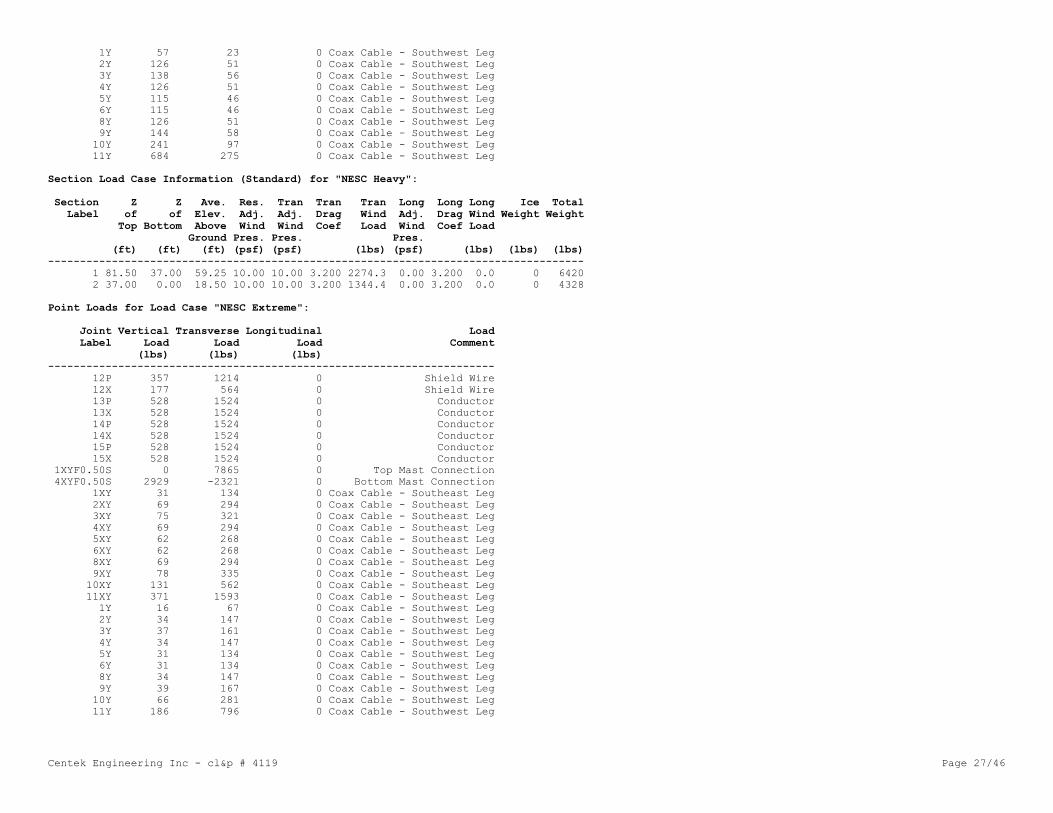
Centek Engineering Inc - cl&p # 4119 Page 27/46
1Y 57 23 0 Coax Cable - Southwest Leg 2Y 126 51 0 Coax Cable - Southwest Leg 3Y 138 56 0 Coax Cable - Southwest Leg 4Y 126 51 0 Coax Cable - Southwest Leg 5Y 115 46 0 Coax Cable - Southwest Leg 6Y 115 46 0 Coax Cable - Southwest Leg 8Y 126 51 0 Coax Cable - Southwest Leg 9Y 144 58 0 Coax Cable - Southwest Leg 10Y 241 97 0 Coax Cable - Southwest Leg 11Y 684 275 0 Coax Cable - Southwest Leg
Section Load Case Information (Standard) for "NESC Heavy":
Section Z Z Ave. Res. Tran Tran Tran Long Long Long Ice Total Label of of Elev. Adj. Adj. Drag Wind Adj. Drag Wind Weight Weight Top Bottom Above Wind Wind Coef Load Wind Coef Load Ground Pres. Pres. Pres. (ft) (ft) (ft) (psf) (psf) (lbs) (psf) (lbs) (lbs) (lbs)------------------------------------------------------------------------------------ 1 81.50 37.00 59.25 10.00 10.00 3.200 2274.3 0.00 3.200 0.0 0 6420 2 37.00 0.00 18.50 10.00 10.00 3.200 1344.4 0.00 3.200 0.0 0 4328
Point Loads for Load Case "NESC Extreme":
Joint Vertical Transverse Longitudinal Load Label Load Load Load Comment (lbs) (lbs) (lbs)---------------------------------------------------------------------- 12P 357 1214 0 Shield Wire 12X 177 564 0 Shield Wire 13P 528 1524 0 Conductor 13X 528 1524 0 Conductor 14P 528 1524 0 Conductor 14X 528 1524 0 Conductor 15P 528 1524 0 Conductor 15X 528 1524 0 Conductor 1XYF0.50S 0 7865 0 Top Mast Connection 4XYF0.50S 2929 -2321 0 Bottom Mast Connection 1XY 31 134 0 Coax Cable - Southeast Leg 2XY 69 294 0 Coax Cable - Southeast Leg 3XY 75 321 0 Coax Cable - Southeast Leg 4XY 69 294 0 Coax Cable - Southeast Leg 5XY 62 268 0 Coax Cable - Southeast Leg 6XY 62 268 0 Coax Cable - Southeast Leg 8XY 69 294 0 Coax Cable - Southeast Leg 9XY 78 335 0 Coax Cable - Southeast Leg 10XY 131 562 0 Coax Cable - Southeast Leg 11XY 371 1593 0 Coax Cable - Southeast Leg 1Y 16 67 0 Coax Cable - Southwest Leg 2Y 34 147 0 Coax Cable - Southwest Leg 3Y 37 161 0 Coax Cable - Southwest Leg 4Y 34 147 0 Coax Cable - Southwest Leg 5Y 31 134 0 Coax Cable - Southwest Leg 6Y 31 134 0 Coax Cable - Southwest Leg 8Y 34 147 0 Coax Cable - Southwest Leg 9Y 39 167 0 Coax Cable - Southwest Leg 10Y 66 281 0 Coax Cable - Southwest Leg 11Y 186 796 0 Coax Cable - Southwest Leg

Centek Engineering Inc - cl&p # 4119 Page 28/46
Section Load Case Information (Code) for "NESC Extreme":
Section Z Z Ave. Res. Tran Tran Tran Tran Tran Tran Long Long Long Long Long Long Ice Total Label of of Elev. Adj. Adj. Angle Gross Soli- Angle Wind Adj. Angle Gross Soli- Angle Wind Weight Weight Top Bottom Above Wind Wind Face Area dity Drag Load Wind Face Area dity Drag Load Ground Pres. Pres. Area Ratio Coef Pres. Area Ratio Coef (ft) (ft) (ft) (psf) (psf) (ft^2) (ft^2) (lbs) (psf) (ft^2) (ft^2) (lbs) (lbs) (lbs)---------------------------------------------------------------------------------------------------------------------------- 1 81.50 37.00 59.25 30.62 30.62 71.07 264.64 0.269 3.200 6964.9 0.00 98.54 431.14 0.229 3.200 0.0 0 4280 2 37.00 0.00 18.50 30.62 30.62 46.22 551.61 0.084 3.200 4528.9 0.00 46.22 551.61 0.084 3.200 0.0 0 2885

Centek Engineering Inc - cl&p # 4119 Page 29/46
*** Analysis Results:
Maximum element usage is 81.86% for Angle "g17X" in load case "NESC Extreme"Maximum insulator usage is 16.01% for Clamp "19" in load case "NESC Extreme"
Angle Forces For All Load Cases: Positive for tension - negative for compression
Group Angle Max. Usage Max. Tens. Max. Comp. LC 1 LC 2 Label Label For All LC For All LC For All LC % (kips) (kips) (kips) (kips)------------------------------------------------------------------ LEG1 g1P 2.37 0.981 -1.079 -1.079 0.981 LEG1 g2P 3.64 0.000 -1.945 -1.661 -1.945 LEG1 g3P 2.67 0.000 -1.429 -1.429 -0.874 LEG1 g4P 2.36 0.689 -1.264 -1.264 0.689

Centek Engineering Inc - cl&p # 4119 Page 30/46
LEG1 g5P 2.39 0.685 -1.280 -1.280 0.685 LEG1 g6P 14.69 7.737 0.000 1.356 7.737 LEG1 g6X 18.35 0.000 -8.969 -4.727 -8.969 LEG1 g6XY 18.80 0.000 -9.192 -5.234 -9.192 LEG1 g6Y 14.03 7.390 0.000 1.207 7.390 LEG1 g7P 29.49 15.536 0.000 4.803 15.536 LEG1 g7X 27.49 0.000 -16.562 -7.736 -16.562 LEG1 g7XY 29.34 0.000 -17.670 -9.133 -17.670 LEG1 g7Y 29.39 15.482 0.000 5.078 15.482 LEG1 g8P 36.81 15.214 0.000 3.852 15.214 LEG1 g8X 28.20 0.000 -16.987 -8.712 -16.987 LEG1 g8XY 29.88 0.000 -17.999 -10.085 -17.999 LEG1 g8Y 36.40 15.047 0.000 4.099 15.047 LEG1 g9P 49.70 26.178 0.000 7.397 26.178 LEG1 g10P 54.08 0.000 -28.936 -14.810 -28.936 LEG1 g11P 56.81 0.000 -30.398 -17.370 -30.398 LEG1 g12P 50.28 26.483 0.000 8.475 26.483 LEG1 g13P 44.52 23.450 0.000 2.375 23.450 LEG1 g14P 65.14 34.316 0.000 10.124 34.316 LEG1 g14X 70.29 0.000 -37.613 -18.985 -37.613 LEG1 g14XY 71.03 0.000 -38.006 -22.452 -38.006 LEG1 g14Y 58.37 30.749 0.000 6.303 30.749 LEG2 g15P 69.77 40.469 0.000 13.433 40.469 LEG2 g15X 66.06 0.000 -43.313 -21.829 -43.313 LEG2 g15XY 65.45 0.000 -42.914 -25.499 -42.914 LEG2 g15Y 62.78 36.413 0.000 9.920 36.413 LEG2 g16P 73.99 42.913 0.000 14.589 42.913 LEG2 g16X 79.12 0.000 -47.133 -25.096 -47.133 LEG2 g16XY 78.47 0.000 -46.744 -27.962 -46.744 LEG2 g16Y 67.87 39.363 0.000 11.171 39.363 LEG2 g17P 64.66 41.952 0.000 14.785 41.952 LEG2 g17X 81.86 0.000 -45.974 -25.577 -45.974 LEG2 g17XY 81.60 0.000 -45.828 -27.774 -45.828 LEG2 g17Y 60.36 39.163 0.000 11.716 39.163 LEG3 g18P 51.23 39.637 0.000 14.457 39.637 LEG3 g18X 56.83 0.000 -48.744 -24.545 -48.744 LEG3 g18XY 57.30 0.000 -49.145 -26.318 -49.145 LEG3 g18Y 49.82 38.543 0.000 11.944 38.543 LEG3 g19P 53.32 41.252 0.000 14.779 41.252 LEG3 g19X 60.16 0.000 -51.214 -26.605 -51.214 LEG3 g19XY 69.00 0.000 -58.744 -29.070 -58.744 LEG3 g19Y 49.82 38.540 0.000 12.631 38.540 XBR1 g20P 15.09 0.000 -1.744 -0.741 -1.744 XBR1 g20X 11.06 1.614 0.000 0.309 1.614 XBR1 g20XY 14.16 2.065 0.000 0.435 2.065 XBR1 g20Y 27.91 0.000 -3.227 -1.126 -3.227 XBR1 g21P 1.41 0.177 -0.122 -0.122 0.177 XBR1 g21X 2.48 0.000 -0.287 -0.134 -0.287 XBR1 g21XY 5.15 0.752 0.000 0.127 0.752 XBR1 g21Y 6.51 0.000 -0.753 -0.360 -0.753 XBR2 g22P 23.60 0.000 -4.077 -2.016 -4.077 XBR2 g22X 18.26 4.181 0.000 2.198 4.181 XBR2 g22XY 35.65 8.164 0.000 3.464 8.164 XBR2 g22Y 44.61 0.000 -7.707 -3.159 -7.707 XBR2 g23P 10.98 2.514 0.000 0.533 2.514 XBR2 g23X 15.03 0.000 -2.596 -0.970 -2.596 XBR2 g23XY 3.07 0.703 -0.258 -0.258 0.703 XBR2 g23Y 4.42 0.000 -0.763 -0.185 -0.763 XBR2 g24P 27.06 0.000 -4.674 -2.365 -4.674 XBR2 g24X 20.11 4.605 0.000 2.148 4.605

Centek Engineering Inc - cl&p # 4119 Page 31/46
XBR2 g24XY 37.38 8.562 0.000 3.401 8.562 XBR2 g24Y 44.84 0.000 -7.746 -3.427 -7.746 XBR2 g25P 4.77 0.327 -0.583 -0.583 0.327 XBR2 g25X 4.08 0.000 -0.705 -0.334 -0.705 XBR2 g25XY 11.24 2.573 0.000 0.371 2.573 XBR2 g25Y 23.52 0.000 -2.878 -1.282 -2.878 XBR2 g26P 27.17 0.000 -5.159 -1.866 -5.159 XBR2 g26X 25.65 5.874 0.000 3.660 5.874 XBR2 g26XY 40.40 9.252 0.000 5.051 9.252 XBR2 g26Y 41.72 0.000 -7.921 -3.085 -7.921 XBR2 g27P 11.20 2.565 0.000 0.682 2.565 XBR2 g27X 18.18 0.000 -2.542 -0.646 -2.542 XBR2 g27XY 2.21 0.307 -0.309 -0.309 0.307 XBR2 g27Y 1.54 0.352 -0.223 0.352 -0.223 XBR2 g28P 30.37 0.000 -5.767 -1.986 -5.767 XBR2 g28X 28.09 6.433 0.000 3.860 6.433 XBR2 g28XY 35.50 8.131 0.000 4.606 8.131 XBR2 g28Y 38.16 0.000 -7.245 -3.232 -7.245 XBR2 g29P 7.67 0.000 -1.072 -1.072 -0.491 XBR2 g29X 0.43 0.098 -0.017 -0.017 0.098 XBR2 g29XY 12.02 2.753 0.000 0.372 2.753 XBR2 g29Y 20.66 0.000 -2.890 -1.252 -2.890 XBR3 g30P 7.80 0.617 -0.975 -0.975 0.617 XBR3 g30X 6.81 0.236 -0.850 0.236 -0.850 XBR3 g30XY 11.86 1.557 0.000 0.617 1.557 XBR3 g30Y 15.66 0.000 -1.957 -1.684 -1.957 XBR3 g31P 10.78 0.000 -1.164 -0.294 -1.164 XBR3 g31X 6.89 0.904 0.000 0.604 0.904 XBR3 g31XY 22.90 3.007 0.000 0.792 3.007 XBR3 g31Y 35.79 0.000 -3.866 -1.798 -3.866 XBR4 g32P 3.32 0.469 -0.381 -0.381 0.469 XBR4 g32X 4.15 0.645 -0.476 0.645 -0.476 XBR4 g32XY 9.36 1.703 0.000 1.221 1.703 XBR4 g32Y 15.06 0.000 -1.730 -0.830 -1.730 XBR4 g33P 15.53 2.827 0.000 1.285 2.827 XBR4 g33X 23.72 0.000 -2.097 -0.544 -2.097 XBR4 g33XY 5.31 0.000 -0.469 -0.439 -0.469 XBR4 g33Y 4.07 0.741 0.000 0.086 0.741 XBR4 g34P 7.30 0.141 -0.666 -0.666 0.141 XBR4 g34X 2.70 0.273 -0.246 0.273 -0.246 XBR4 g34XY 8.86 1.612 0.000 0.662 1.612 XBR4 g34Y 20.77 0.000 -1.895 -1.265 -1.895 XBR4 g35P 7.43 0.000 -0.517 -0.060 -0.517 XBR4 g35X 1.54 0.280 0.000 0.280 0.267 XBR4 g35XY 8.25 1.501 0.000 0.317 1.501 XBR4 g35Y 31.21 0.000 -2.174 -0.997 -2.174 XBR5 g36P 20.86 0.000 -1.323 -1.323 -1.141 XBR5 g36X 2.15 0.000 -0.136 -0.098 -0.136 XBR5 g36XY 11.35 1.876 0.000 0.282 1.876 XBR5 g36Y 65.98 0.000 -4.186 -2.337 -4.186 XBR5 g37P 45.98 1.684 -2.917 -2.917 1.684 XBR5 g37X 27.94 4.616 0.000 1.758 4.616 XBR5 g37XY 35.10 5.800 0.000 1.707 5.800 XBR5 g37Y 61.37 0.000 -3.894 -3.894 0.000 XBR6 g38P 31.31 0.000 -1.553 -1.492 -1.553 XBR6 g38X 1.83 0.242 -0.083 -0.083 0.242 XBR6 g38XY 67.31 8.886 0.000 0.733 8.886 XBR6 g38Y 59.31 0.000 -2.942 -2.942 0.000 XBR6 g39P 64.16 1.375 -3.183 -3.183 1.375 XBR6 g39X 35.90 4.740 0.000 1.908 4.740

Centek Engineering Inc - cl&p # 4119 Page 32/46
XBR6 g39XY 42.02 5.547 0.000 1.609 5.547 XBR6 g39Y 81.50 0.000 -4.043 -4.043 0.000 HORZ1 g40P 6.37 0.492 0.000 0.492 0.408 HORZ1 g40Y 9.18 0.709 0.000 0.709 0.699 HORZ1 g41P 36.49 2.816 0.000 2.816 0.305 HORZ1 g41X 49.53 0.000 -4.507 -1.561 -4.507 HORZ2 g42P 7.67 0.698 0.000 0.650 0.698 HORZ2 g42Y 33.17 0.783 -3.019 0.783 -3.019 HORZ2 g43P 46.17 4.202 -0.983 4.202 -0.983 HORZ2 g43X 70.36 0.000 -6.403 -2.321 -6.403 ARM1 g44P 3.29 0.050 -0.487 0.050 -0.487 ARM1 g44X 4.23 0.769 0.000 0.769 0.476 ARM1 g44XY 4.20 0.765 0.000 0.765 0.461 ARM1 g44Y 3.45 0.045 -0.511 0.045 -0.511 ARM1 g45P 5.93 2.563 0.000 2.563 0.787 ARM1 g45Y 4.98 2.154 -0.726 2.154 -0.726 ARM1 g46P 14.55 0.000 -3.619 -3.619 -1.628 ARM1 g46X 7.67 0.000 -1.908 -1.908 -0.119 ARM1 g46XY 7.10 0.362 -1.767 -1.767 0.362 ARM1 g46Y 15.06 0.000 -3.745 -3.745 -2.060 ARM1 g47P 9.69 0.000 -2.540 -2.540 -0.687 ARM1 g47Y 12.09 0.000 -3.171 -3.171 -2.984 ARM2 g48P 28.05 0.000 -4.154 -4.154 -1.791 ARM2 g48X 20.76 0.000 -3.075 -3.075 -0.492 ARM2 g48XY 20.14 0.000 -2.983 -2.983 -0.137 ARM2 g48Y 28.83 0.000 -4.270 -4.270 -2.268 ARM2 g49P 12.68 0.000 -3.723 -3.723 -1.220 ARM2 g49Y 12.45 0.000 -3.656 -3.656 -1.065 ARM1 g50P 11.68 0.000 -2.126 -2.126 -1.116 ARM1 g50X 5.73 0.000 -1.042 -1.042 -0.062 ARM1 g50XY 4.83 0.879 -0.660 -0.660 0.879 ARM1 g50Y 11.09 0.000 -2.019 -2.019 -1.642 ARM1 g51P 8.28 0.000 -2.172 -2.172 -0.855 ARM1 g51Y 8.45 0.000 -2.217 -2.217 -1.101 M1 g52P 13.56 0.000 -0.786 -0.786 -0.084 M1 g52X 15.65 0.000 -0.908 -0.908 -0.229 M1 g53P 10.50 0.810 -0.166 0.810 -0.166 M1 g53X 21.81 1.683 0.000 1.683 1.133 M1 g54P 9.60 0.741 0.000 0.741 0.177 M1 g54X 11.76 0.907 0.000 0.907 0.314 M1 g55P 43.18 0.000 -2.504 -0.928 -2.504 M1 g55X 36.83 2.842 0.000 1.558 2.842 M2 g56P 6.72 0.518 0.000 0.290 0.518 M2 g56X 7.26 0.000 -0.661 -0.020 -0.661 M2 g57P 9.12 0.704 0.000 0.118 0.704 M2 g57X 11.97 0.000 -1.089 -0.223 -1.089 M2 g58P 7.59 0.000 -0.539 -0.539 -0.200 M2 g58X 3.17 0.000 -0.225 -0.225 -0.047 M2 g59P 0.99 0.076 -0.057 -0.057 0.076 M2 g59X 9.37 0.000 -0.666 -0.666 -0.370 M3 g60P 20.12 0.000 -1.831 -1.831 -0.612 M3 g60X 12.59 0.000 -1.145 -1.145 -0.335 M4 g61P 36.11 2.849 0.000 2.849 0.657 M4 g61X 32.20 2.541 0.000 2.541 1.078 M4 g61XY 29.99 2.366 0.000 2.366 0.473 M4 g61Y 37.99 2.997 0.000 2.997 1.157 M4 g62P 46.52 3.670 0.000 3.670 0.980 M4 g62X 47.75 3.767 0.000 3.767 1.401 M4 g62XY 46.48 3.667 0.000 3.667 1.006 M4 g62Y 47.96 3.784 0.000 3.784 1.445

Centek Engineering Inc - cl&p # 4119 Page 33/46
M4 g63P 22.48 1.774 0.000 1.774 0.290 M4 g63X 24.32 1.918 0.000 1.918 1.111 M4 g63XY 18.57 1.465 -0.015 1.465 -0.015 M4 g63Y 20.85 1.645 0.000 1.645 0.890 M4 g64P 42.71 3.369 0.000 3.369 1.086 M4 g64Y 41.47 3.271 0.000 3.271 0.727

Centek Engineering Inc - cl&p # 4119 Page 34/46
*** Analysis Results for Load Case No. 1 "NESC Heavy" - Number of iterations in SAPS 9
Equilibrium Joint Positions and Rotations for Load Case "NESC Heavy":
Joint X-Displ Y-Displ Z-Displ X-Rot Y-Rot Z-Rot X-Pos Y-Pos Z-Pos Label (ft) (ft) (ft) (deg) (deg) (deg) (ft) (ft) (ft)--------------------------------------------------------------------------------------- 1P -0.00985 0.1572 -0.01559 -0.2347 -0.0151 -0.0349 2.49 2.657 81.48 2P -0.007939 0.1368 -0.0154 -0.2327 -0.0394 -0.0317 2.492 2.637 76.48 3P -0.005527 0.1132 -0.01485 -0.2138 0.0447 -0.0276 2.494 2.613 70.49 4P -0.004228 0.08949 -0.01392 -0.2247 -0.0824 -0.0226 2.496 2.589 64.49 5P -0.001418 0.07285 -0.01257 -0.1881 0.0038 -0.0179 2.499 2.573 59.49 6P -0.001923 0.05627 -0.01086 -0.1652 -0.0136 -0.0130 2.498 2.556 54.49 7P 0 0 0 0.0000 0.0000 0.0000 10 10 0 12P -0.02013 0.1585 0.04114 -0.2138 -0.0720 -0.0374 -0.02013 -13.59 81.54 13P -0.01557 0.1397 0.0267 -0.1417 0.0219 -0.0369 -0.01557 -9.61 76.53 14P -0.01149 0.0923 0.02252 -0.0465 -0.0131 -0.0239 -0.01149 -14.16 64.52 15P -0.005828 0.05797 0.02107 -0.1415 -0.0124 -0.0191 -0.005828 -10.19 54.52 1X -0.01299 0.1569 0.004147 -0.2190 -0.0248 -0.0360 2.487 -2.343 81.5 1XY -0.01273 0.1601 0.002359 -0.0817 -0.0264 -0.0351 -2.513 -2.34 81.5 1Y -0.00963 0.1604 -0.01734 -0.2568 -0.0260 -0.0355 -2.51 2.66 81.48 2X -0.01079 0.1372 0.004282 -0.2281 -0.0296 -0.0352 2.489 -2.363 76.5 2XY -0.01126 0.1403 0.002522 -0.3294 -0.0056 -0.0329 -2.511 -2.36 76.5 2Y -0.008163 0.1399 -0.01717 -0.2215 0.0016 -0.0353 -2.508 2.64 76.48 3X -0.009456 0.1124 0.004189 -0.2349 0.0313 -0.0313 2.491 -2.388 70.5 3XY -0.008086 0.1148 0.002448 -0.2234 -0.0792 -0.0277 -2.508 -2.385 70.5 3Y -0.006738 0.1158 -0.01657 -0.2237 -0.0795 -0.0306 -2.507 2.616 70.48 4X -0.006386 0.08997 0.003773 -0.1999 -0.0679 -0.0267 2.494 -2.41 64.5 4XY -0.006637 0.09206 0.002005 -0.2184 0.0288 -0.0231 -2.507 -2.408 64.5 4Y -0.004433 0.09159 -0.01549 -0.2223 0.0476 -0.0268 -2.504 2.592 64.48 5X -0.005654 0.07109 0.003151 -0.2000 -0.0070 -0.0257 2.494 -2.429 59.5 5XY -0.003897 0.07266 0.001562 -0.1774 -0.0318 -0.0174 -2.504 -2.427 59.5 5Y -0.004467 0.0749 -0.01392 -0.1925 -0.0344 -0.0244 -2.504 2.575 59.49 6X -0.003069 0.05658 0.002273 -0.1476 -0.0193 -0.0243 2.497 -2.443 54.5 6XY -0.003502 0.05824 0.001023 -0.1525 -0.0098 -0.0122 -2.504 -2.442 54.5 6Y -0.001664 0.05793 -0.01189 -0.1649 -0.0052 -0.0223 -2.502 2.558 54.49 7X 0 0 0 0.0000 0.0000 0.0000 10 -10 0 7XY 0 0 0 0.0000 0.0000 0.0000 -10 -10 0 7Y 0 0 0 0.0000 0.0000 0.0000 -10 10 0 12X -0.00259 0.1589 -0.06722 -0.2655 -0.0282 -0.0368 -0.00259 13.91 81.43 13X -0.003616 0.1378 -0.04993 -0.2794 -0.0152 -0.0357 -0.003616 9.888 76.45 14X 0.0006713 0.08942 -0.08486 -0.3913 -0.0167 -0.0241 0.0006713 14.34 64.42 15X 0.0009133 0.0569 -0.04113 -0.2450 -0.0107 -0.0210 0.0009133 10.31 54.46 8S 0.0002479 0.04439 -0.01055 -0.1159 -0.0203 -0.0100 3.188 3.232 49.49 9S 0.000491 0.03241 -0.009911 -0.0991 0.0013 -0.0082 4.014 4.046 43.49 10S 0.000629 0.0225 -0.00877 -0.0704 -0.0051 -0.0089 4.909 4.931 36.99 11S 0.001332 0.008242 -0.006175 -0.0376 -0.0018 -0.0073 6.905 6.912 22.49 16S -0.01062 0.1006 0.003956 -0.2128 -0.0349 -0.0290 2.489 -2.399 67.5 1XYF0.50S -0.01176 0.1554 0.00242 -0.2368 -0.0176 -0.0340 -2.512 -2.345 79 4XYF0.50S -0.005929 0.08129 0.001652 -0.2338 -0.0460 -0.0201 -2.506 -2.419 62 8X -0.003102 0.04383 0.003037 -0.1273 -0.0015 -0.0237 3.185 -3.144 49.5 8XY -0.001592 0.04564 0.001771 -0.1289 -0.0216 -0.0090 -3.19 -3.142 49.5 8Y -0.002434 0.04656 -0.01144 -0.1149 0.0123 -0.0203 -3.191 3.235 49.49 9X -0.00193 0.03211 0.003518 -0.0931 -0.0133 -0.0171 4.012 -3.982 43.5 9XY -0.001079 0.03437 0.002261 -0.0933 -0.0038 -0.0107 -4.015 -3.979 43.5 9Y -0.001407 0.03483 -0.01068 -0.1006 -0.0083 -0.0172 -4.015 4.049 43.49 10X -0.001177 0.0223 0.003546 -0.0718 -0.0042 -0.0151 4.907 -4.886 37

Centek Engineering Inc - cl&p # 4119 Page 35/46
10XY -0.000524 0.02487 0.002365 -0.0730 -0.0083 -0.0067 -4.909 -4.883 37 10Y -0.0005472 0.02515 -0.009432 -0.0708 0.0006 -0.0115 -4.909 4.933 36.99 11X -0.0004291 0.008008 0.002999 -0.0378 -0.0023 -0.0098 6.903 -6.896 22.5 11XY 0.0004147 0.01056 0.002044 -0.0424 -0.0029 -0.0030 -6.903 -6.893 22.5 11Y -0.000195 0.01084 -0.006668 -0.0418 0.0023 -0.0043 -6.904 6.915 22.49 16X -0.008026 0.1019 -0.01441 -0.2303 -0.0095 -0.0251 2.492 2.602 67.49 16XY -0.00247 0.1041 -0.01605 -0.2358 -0.0252 -0.0286 -2.502 2.604 67.48 16Y -0.004507 0.1028 0.002204 -0.2154 -0.0086 -0.0255 -2.505 -2.397 67.5
Joint Support Reactions for Load Case "NESC Heavy":
Joint X X Y Y H-Shear Z Comp. Uplift Result. Result. X X-M. Y Y-M. H-Bend-M Z Z-M. Max. Label Force Usage Force Usage Usage Force Usage Usage Force Usage Moment Usage Moment Usage Usage Moment Usage Usage (kips) %(kips) % % (kips) % % (kips) % (ft-k) % (ft-k) % % (ft-k) % %-------------------------------------------------------------------------------------------------------------------------------- 7P -6.17 0.0 -4.92 0.0 0.0 -30.80 0.0 0.0 31.79 0.0 0.02 0.0 -0.0 0.0 0.0 0.00 0.0 0.0 7X 2.95 0.0 -2.31 0.0 0.0 15.43 0.0 0.0 15.88 0.0 0.02 0.0 -0.0 0.0 0.0 0.01 0.0 0.0 7XY -2.93 0.0 -2.55 0.0 0.0 14.21 0.0 0.0 14.73 0.0 0.05 0.0 -0.0 0.0 0.0 -0.00 0.0 0.0 7Y 6.15 0.0 -6.02 0.0 0.0 -33.69 0.0 0.0 34.77 0.0 0.04 0.0 -0.0 0.0 0.0 -0.00 0.0 0.0
Joint Displacements, Loads and Member Forces on Joints for Load Case "NESC Heavy":
Joint X External Y External Z External X Member Y Member Z Member X Y Z Label Load Load Load Force Force Force Disp. Disp. Disp. (kips) (kips) (kips) (kips) (kips) (kips) (ft) (ft) (ft)--------------------------------------------------------------------------------------------- 1P 0.0000 0.0000 -0.1359 -0.0000 0.0000 0.1359 -0.0098 0.1572 -0.0156 2P 0.0000 0.0000 -0.1749 -0.0000 0.0000 0.1749 -0.0079 0.1368 -0.0154 3P 0.0000 0.0000 -0.1165 0.0000 0.0000 0.1165 -0.0055 0.1132 -0.0148 4P 0.0000 0.0000 -0.1898 -0.0000 0.0000 0.1898 -0.0042 0.0895 -0.0139 5P 0.0000 0.0000 -0.1290 -0.0000 0.0000 0.1290 -0.0014 0.0729 -0.0126 6P 0.0000 0.0000 -0.1800 -0.0000 0.0000 0.1800 -0.0019 0.0563 -0.0109 7P 0.0000 0.0000 -0.2844 6.1720 4.9166 -30.5157 0.0000 0.0000 0.0000 12P 0.0000 1.0447 -1.4255 -0.0000 -1.0447 1.4255 -0.0201 0.1585 0.0411 13P 0.0000 1.1845 -1.8040 -0.0000 -1.1845 1.8040 -0.0156 0.1397 0.0267 14P 0.0000 1.1622 -1.8354 -0.0000 -1.1622 1.8354 -0.0115 0.0923 0.0225 15P 0.0000 1.1678 -1.7936 -0.0000 -1.1678 1.7936 -0.0058 0.0580 0.0211 1X 0.0000 0.0681 -0.1359 -0.0000 -0.0681 0.1359 -0.0130 0.1569 0.0041 1XY 0.0000 0.0977 -0.2386 -0.0000 -0.0977 0.2386 -0.0127 0.1601 0.0024 1Y 0.0000 0.0230 -0.1929 -0.0000 -0.0230 0.1929 -0.0096 0.1604 -0.0173 2X 0.0000 0.1164 -0.1749 -0.0000 -0.1164 0.1749 -0.0108 0.1372 0.0043 2XY 0.0000 0.1971 -0.4155 -0.0000 -0.1971 0.4155 -0.0113 0.1403 0.0025 2Y 0.0000 0.0510 -0.3009 -0.0000 -0.0510 0.3009 -0.0082 0.1399 -0.0172 3X 0.0000 0.1105 -0.1165 0.0000 -0.1105 0.1165 -0.0095 0.1124 0.0042 3XY 0.0000 0.2135 -0.3925 -0.0000 -0.2135 0.3925 -0.0081 0.1148 0.0024 3Y 0.0000 0.0560 -0.2545 -0.0000 -0.0560 0.2545 -0.0067 0.1158 -0.0166 4X 0.0000 0.1139 -0.1898 -0.0000 -0.1139 0.1898 -0.0064 0.0900 0.0038 4XY 0.0000 0.1945 -0.4305 -0.0000 -0.1945 0.4305 -0.0066 0.0921 0.0020 4Y 0.0000 0.0510 -0.3158 -0.0000 -0.0510 0.3158 -0.0044 0.0916 -0.0155 5X 0.0000 0.1248 -0.1290 -0.0000 -0.1248 0.1290 -0.0057 0.0711 0.0032 5XY 0.0000 0.1975 -0.3466 -0.0000 -0.1975 0.3466 -0.0039 0.0727 0.0016 5Y 0.0000 0.0460 -0.2440 -0.0000 -0.0460 0.2440 -0.0045 0.0749 -0.0139 6X 0.0000 0.1121 -0.1800 -0.0000 -0.1121 0.1800 -0.0031 0.0566 0.0023 6XY 0.0000 0.1981 -0.4100 -0.0000 -0.1981 0.4100 -0.0035 0.0582 0.0010 6Y 0.0000 0.0460 -0.2950 -0.0000 -0.0460 0.2950 -0.0017 0.0579 -0.0119 7X 0.0000 0.1868 -0.2844 -2.9474 2.1281 15.7193 0.0000 0.0000 0.0000 7XY 0.0000 0.1868 -0.2844 2.9255 2.3605 14.4957 0.0000 0.0000 0.0000 7Y 0.0000 0.0000 -0.2844 -6.1501 6.0189 -33.4038 0.0000 0.0000 0.0000

Centek Engineering Inc - cl&p # 4119 Page 36/46
12X 0.0000 0.7790 -0.9005 -0.0000 -0.7790 0.9005 -0.0026 0.1589 -0.0672 13X 0.0000 1.1180 -1.8040 -0.0000 -1.1180 1.8040 -0.0036 0.1378 -0.0499 14X 0.0000 1.1180 -1.8354 -0.0000 -1.1180 1.8354 0.0007 0.0894 -0.0849 15X 0.0000 1.1180 -1.7936 -0.0000 -1.1180 1.7936 0.0009 0.0569 -0.0411 8S 0.0000 0.0000 -0.1356 -0.0000 0.0000 0.1356 0.0002 0.0444 -0.0106 9S 0.0000 0.0000 -0.1628 -0.0000 0.0000 0.1628 0.0005 0.0324 -0.0099 10S 0.0000 0.0000 -0.3323 0.0000 0.0000 0.3323 0.0006 0.0225 -0.0088 11S 0.0000 0.0000 -0.5923 0.0000 0.0000 0.5923 0.0013 0.0082 -0.0062 16S 0.0000 0.0424 -0.0558 -0.0000 -0.0424 0.0558 -0.0106 0.1006 0.0040 1XYF0.50S 0.0000 2.1637 -0.0248 0.0000 -2.1637 0.0248 -0.0118 0.1554 0.0024 4XYF0.50S 0.0000 -0.5783 -6.0978 -0.0000 0.5783 6.0977 -0.0059 0.0813 0.0017 8X 0.0000 0.1107 -0.1356 -0.0000 -0.1107 0.1356 -0.0031 0.0438 0.0030 8XY 0.0000 0.2047 -0.3886 0.0000 -0.2047 0.3886 -0.0016 0.0456 0.0018 8Y 0.0000 0.0510 -0.2616 0.0000 -0.0510 0.2616 -0.0024 0.0466 -0.0114 9X 0.0000 0.1353 -0.1628 -0.0000 -0.1353 0.1628 -0.0019 0.0321 0.0035 9XY 0.0000 0.2423 -0.4498 -0.0000 -0.2423 0.4498 -0.0011 0.0344 0.0023 9Y 0.0000 0.0580 -0.3068 -0.0000 -0.0580 0.3068 -0.0014 0.0348 -0.0107 10X 0.0000 0.2262 -0.3323 -0.0000 -0.2262 0.3323 -0.0012 0.0223 0.0035 10XY 0.0000 0.4062 -0.8153 -0.0000 -0.4062 0.8153 -0.0005 0.0249 0.0024 10Y 0.0000 0.0970 -0.5733 -0.0000 -0.0970 0.5733 -0.0005 0.0252 -0.0094 11X 0.0000 0.3637 -0.5923 -0.0000 -0.3637 0.5923 -0.0004 0.0080 0.0030 11XY 0.0000 0.8747 -1.9603 -0.0000 -0.8747 1.9603 0.0004 0.0106 0.0020 11Y 0.0000 0.2750 -1.2763 -0.0000 -0.2750 1.2763 -0.0002 0.0108 -0.0067 16X 0.0000 0.0000 -0.0558 -0.0000 0.0000 0.0558 -0.0080 0.1019 -0.0144 16XY 0.0000 0.0000 -0.0558 0.0000 0.0000 0.0558 -0.0025 0.1041 -0.0161 16Y 0.0000 0.0424 -0.0558 0.0000 -0.0424 0.0558 -0.0045 0.1028 0.0022
Crossing Diagonal Check for Load Case "NESC Heavy" (RLOUT controls):
Comp. Tens. Connect Force Force | ------------------Original------------------ | ------------Alternate----------- | Member Member Leg for In In | ------------------Supported----------------- | -----------Unsupported---------- | Label Label Comp. Comp. Tens. | L/R RLX RLY RLZ L/R KL/R Curve | L/R RLOUT L/R KL/R Curve | Member Member Member | Cap. No. | Cap. No. | (kips) (kips) | (kips) | (kips) |--------------------------------------------------------------------------------------------------------------------------- g21P g21Y Short only -0.12 -0.36 11.56 0.750 0.500 0.500 123.69 122.85 5 8.63 1.000 158.01 143.38 6 g21Y g21P Short only -0.36 -0.12 11.56 0.750 0.500 0.500 123.69 122.85 5 8.63 1.000 158.01 143.38 6 g23X g23XY Long only -0.97 -0.26 17.27 0.500 0.750 0.500 120.57 120.47 5 12.24 1.000 160.76 145.07 6 g23XY g23X Long only -0.26 -0.97 17.27 0.500 0.750 0.500 120.57 120.47 5 12.24 1.000 160.76 145.07 6 g25P g25Y Long only -0.58 -1.28 17.27 0.500 0.750 0.500 120.57 120.47 5 12.24 1.000 160.76 145.07 6 g25Y g25P Long only -1.28 -0.58 17.27 0.500 0.750 0.500 120.57 120.47 5 12.24 1.000 160.76 145.07 6 g27X g27XY Long only -0.65 -0.31 18.99 0.500 0.750 0.500 109.16 111.87 2 13.99 1.000 145.55 135.71 6 g27XY g27X Long only -0.31 -0.65 18.99 0.500 0.750 0.500 109.16 111.87 2 13.99 1.000 145.55 135.71 6 g29P g29Y Long only -1.07 -1.25 18.99 0.500 0.750 0.500 109.16 111.87 2 13.99 1.000 145.55 135.71 6 g29Y g29P Long only -1.25 -1.07 18.99 0.500 0.750 0.500 109.16 111.87 2 13.99 1.000 145.55 135.71 6 g31P g31Y Short only -0.29 -1.80 12.49 0.779 0.559 0.559 129.47 127.26 5 10.80 1.000 147.90 137.16 6 g31Y g31P Short only -1.80 -0.29 12.49 0.779 0.559 0.559 129.47 127.26 5 10.80 1.000 147.90 137.16 6 g33X g33XY Long only -0.54 -0.44 11.49 0.563 0.781 0.563 148.89 142.05 5 8.84 1.000 188.20 161.94 6 g33XY g33X Long only -0.44 -0.54 11.49 0.563 0.781 0.563 148.89 142.05 5 8.84 1.000 188.20 161.94 6 g35P g35Y Long only -0.06 -1.00 9.12 0.550 0.775 0.550 171.66 159.41 5 6.97 1.000 221.50 182.42 6 g35Y g35P Long only -1.00 -0.06 9.12 0.550 0.775 0.550 171.66 159.41 5 6.97 1.000 221.50 182.42 6 g58P g58X Short only -0.54 -0.23 11.44 0.750 0.500 0.500 123.69 123.69 4 7.11 1.000 158.01 158.01 4 g58X g58P Short only -0.23 -0.54 11.44 0.750 0.500 0.500 123.69 123.69 4 7.11 1.000 158.01 158.01 4 g59P g59X Short only -0.06 -0.67 11.44 0.750 0.500 0.500 123.69 123.69 4 7.11 1.000 158.01 158.01 4 g59X g59P Short only -0.67 -0.06 11.44 0.750 0.500 0.500 123.69 123.69 4 7.11 1.000 158.01 158.01 4
Summary of Clamp Capacities and Usages for Load Case "NESC Heavy":

Centek Engineering Inc - cl&p # 4119 Page 37/46
Clamp Force Input Factored Usage Label Holding Holding Capacity Capacity (kips) (kips) (kips) %---------------------------------------- 1 1.767 50.00 50.00 3.53 2 1.191 50.00 50.00 2.38 3 2.158 50.00 50.00 4.32 4 2.122 50.00 50.00 4.24 5 2.172 50.00 50.00 4.34 6 2.149 50.00 50.00 4.30 7 2.140 50.00 50.00 4.28 8 2.114 50.00 50.00 4.23 9 0.258 50.00 50.00 0.52 10 0.460 50.00 50.00 0.92 11 0.447 50.00 50.00 0.89 12 0.472 50.00 50.00 0.94 13 0.399 50.00 50.00 0.80 14 0.455 50.00 50.00 0.91 15 0.439 50.00 50.00 0.88 16 0.511 50.00 50.00 1.02 17 0.911 50.00 50.00 1.82 18 2.147 50.00 50.00 4.29 19 2.164 50.00 50.00 4.33 20 6.125 50.00 50.00 12.25 21 0.194 50.00 50.00 0.39 22 0.305 50.00 50.00 0.61 23 0.261 50.00 50.00 0.52 24 0.320 50.00 50.00 0.64 25 0.248 50.00 50.00 0.50 26 0.299 50.00 50.00 0.60 27 0.266 50.00 50.00 0.53 28 0.312 50.00 50.00 0.62 29 0.581 50.00 50.00 1.16 30 1.306 50.00 50.00 2.61

Centek Engineering Inc - cl&p # 4119 Page 38/46
*** Analysis Results for Load Case No. 2 "NESC Extreme" - Number of iterations in SAPS 10
Equilibrium Joint Positions and Rotations for Load Case "NESC Extreme":
Joint X-Displ Y-Displ Z-Displ X-Rot Y-Rot Z-Rot X-Pos Y-Pos Z-Pos Label (ft) (ft) (ft) (deg) (deg) (deg) (ft) (ft) (ft)------------------------------------------------------------------------------------- 1P -0.003061 0.3531 -0.02701 -0.5358 -0.0266 -0.2213 2.497 2.853 81.47 2P -0.0005027 0.3064 -0.02662 -0.5358 -0.0477 -0.2139 2.499 2.806 76.47 3P 0.003788 0.251 -0.02541 -0.4970 0.0027 -0.1983 2.504 2.751 70.47 4P 0.004835 0.1981 -0.02338 -0.4953 -0.0678 -0.1815 2.505 2.698 64.48 5P 0.01003 0.1584 -0.02065 -0.4316 -0.0142 -0.1690 2.51 2.658 59.48 6P 0.008792 0.1234 -0.01718 -0.3453 -0.0219 -0.1563 2.509 2.623 54.48 7P 0 0 0 0.0000 0.0000 0.0000 10 10 0 12P -0.06729 0.3639 0.1202 -0.6517 -0.2246 -0.2280 -0.06729 -13.39 81.62 13P -0.0477 0.3172 0.08341 -0.4221 0.1185 -0.2299 -0.0477 -9.433 76.58 14P -0.04856 0.2074 0.1133 -0.4542 -0.0090 -0.1828 -0.04856 -14.04 64.61 15P -0.02662 0.1313 0.06408 -0.4156 -0.0184 -0.1626 -0.02662 -10.12 54.56 1X -0.02255 0.3533 0.01884 -0.5211 -0.0555 -0.2222 2.477 -2.147 81.52 1XY -0.02245 0.3731 0.01567 -0.0146 -0.0576 -0.2222 -2.522 -2.127 81.52 1Y -0.002998 0.3728 -0.02998 -0.6165 -0.0437 -0.2208 -2.503 2.873 81.47 2X -0.01917 0.3067 0.01898 -0.5391 -0.0244 -0.2162 2.481 -2.193 76.52 2XY -0.01944 0.3262 0.01597 -0.9102 -0.0264 -0.2166 -2.519 -2.174 76.52 2Y -0.0004188 0.3255 -0.02967 -0.4944 -0.0115 -0.2154 -2.5 2.826 76.47 3X -0.01675 0.2509 0.01841 -0.5027 -0.0368 -0.1995 2.483 -2.249 70.52 3XY -0.01358 0.2681 0.01546 -0.4626 -0.0635 -0.1991 -2.514 -2.232 70.52 3Y 0.0006316 0.2687 -0.02843 -0.5330 -0.0519 -0.1985 -2.499 2.769 70.47 4X -0.01102 0.1984 0.017 -0.4885 -0.0354 -0.1829 2.489 -2.302 64.52 4XY -0.01108 0.2142 0.01408 -0.5559 -0.0339 -0.1827 -2.511 -2.286 64.51 4Y 0.004811 0.2139 -0.02627 -0.4930 0.0077 -0.1826 -2.495 2.714 64.47 5X -0.01052 0.1579 0.01484 -0.4350 -0.0421 -0.1719 2.489 -2.342 59.51 5XY -0.005016 0.1724 0.01205 -0.3504 -0.0379 -0.1705 -2.505 -2.328 59.51 5Y 0.003935 0.1734 -0.0234 -0.4460 -0.0373 -0.1708 -2.496 2.673 59.48 6X -0.004333 0.1237 0.01191 -0.3391 -0.0355 -0.1607 2.496 -2.376 54.51 6XY -0.005104 0.1377 0.009434 -0.3666 -0.0306 -0.1591 -2.505 -2.362 54.51 6Y 0.009509 0.1374 -0.01989 -0.3537 -0.0298 -0.1590 -2.49 2.637 54.48 7X 0 0 0 0.0000 0.0000 0.0000 10 -10 0 7XY 0 0 0 0.0000 0.0000 0.0000 -10 -10 0 7Y 0 0 0 0.0000 0.0000 0.0000 -10 10 0 12X 0.04129 0.3625 -0.1354 -0.5311 -0.0628 -0.2272 0.04129 14.11 81.36 13X 0.02752 0.3156 -0.09742 -0.5581 -0.0146 -0.2240 0.02752 10.07 76.4 14X 0.04231 0.2053 -0.1387 -0.5801 -0.0295 -0.1826 0.04231 14.46 64.36 15X 0.03115 0.1304 -0.07586 -0.4598 -0.0314 -0.1645 0.03115 10.38 54.42 8S 0.0152 0.09624 -0.01674 -0.2492 -0.0587 -0.1452 3.203 3.284 49.48 9S 0.01985 0.06994 -0.01544 -0.1998 -0.0191 -0.1300 4.034 4.084 43.48 10S 0.02288 0.0482 -0.01353 -0.1438 -0.0052 -0.1170 4.931 4.956 36.99 11S 0.01928 0.01676 -0.009472 -0.0747 0.0342 -0.0756 6.923 6.92 22.49 16S -0.01424 0.225 0.01769 -0.5036 -0.0671 -0.1909 2.486 -2.275 67.52 1XYF0.50S -0.02054 0.3684 0.01564 -0.5746 -0.0345 -0.2193 -2.521 -2.132 79.02 4XYF0.50S -0.008111 0.1887 0.01303 -0.4915 -0.0885 -0.1762 -2.508 -2.311 62.01 8X -0.006085 0.09612 0.01252 -0.2531 -0.0015 -0.1500 3.182 -3.092 49.51 8XY -0.00152 0.112 0.009824 -0.2711 -0.0600 -0.1498 -3.19 -3.076 49.51 8Y 0.01073 0.1124 -0.02025 -0.2700 0.0120 -0.1475 -3.177 3.3 49.48 9X -0.004427 0.06997 0.01256 -0.1978 -0.0359 -0.1329 4.009 -3.944 43.51 9XY -0.001679 0.08809 0.00966 -0.2187 -0.0144 -0.1418 -4.015 -3.926 43.51 9Y 0.01552 0.08805 -0.02002 -0.2193 -0.0444 -0.1410 -3.998 4.102 43.48 10X -0.00343 0.04809 0.01168 -0.1452 -0.0152 -0.1236 4.905 -4.86 37.01

Centek Engineering Inc - cl&p # 4119 Page 39/46
10XY -0.001525 0.06803 0.008633 -0.1599 -0.0284 -0.1244 -4.91 -4.84 37.01 10Y 0.02277 0.06825 -0.01927 -0.1587 -0.0206 -0.1233 -4.885 4.977 36.98 11X -0.002503 0.01653 0.00899 -0.0737 -0.0126 -0.0866 6.901 -6.887 22.51 11XY -0.0001563 0.03954 0.005399 -0.1137 -0.0164 -0.0808 -6.904 -6.864 22.51 11Y 0.01966 0.03841 -0.014 -0.1136 0.0496 -0.0687 -6.884 6.942 22.49 16X 0.002817 0.2253 -0.02441 -0.5097 -0.0024 -0.1902 2.503 2.725 67.48 16XY 0.003914 0.2415 -0.02736 -0.5288 -0.0521 -0.1903 -2.496 2.741 67.47 16Y -0.01141 0.2414 0.01476 -0.5168 -0.0154 -0.1912 -2.511 -2.259 67.51
Joint Support Reactions for Load Case "NESC Extreme":
Joint X X Y Y H-Shear Z Comp. Uplift Result. Result. X X-M. Y Y-M. H-Bend-M Z Z-M. Max. Label Force Usage Force Usage Usage Force Usage Usage Force Usage Moment Usage Moment Usage Usage Moment Usage Usage (kips) % (kips) % % (kips) % % (kips) % (ft-k) % (ft-k) % % (ft-k) % %--------------------------------------------------------------------------------------------------------------------------------- 7P -7.06 0.0 -8.19 0.0 0.0 -51.76 0.0 0.0 52.87 0.0 0.04 0.0 -0.1 0.0 0.0 0.02 0.0 0.0 7X 8.91 0.0 -6.73 0.0 0.0 44.85 0.0 0.0 46.22 0.0 0.03 0.0 0.0 0.0 0.0 0.04 0.0 0.0 7XY -9.01 0.0 -11.50 0.0 0.0 48.40 0.0 0.0 50.56 0.0 0.25 0.0 0.0 0.0 0.0 0.01 0.0 0.0 7Y 7.16 0.0 -8.08 0.0 0.0 -56.82 0.0 0.0 57.83 0.0 0.23 0.0 -0.2 0.0 0.0 -0.01 0.0 0.0
Joint Displacements, Loads and Member Forces on Joints for Load Case "NESC Extreme":
Joint X External Y External Z External X Member Y Member Z Member X Y Z Label Load Load Load Force Force Force Disp. Disp. Disp. (kips) (kips) (kips) (kips) (kips) (kips) (ft) (ft) (ft)--------------------------------------------------------------------------------------------- 1P 0.0000 0.1393 -0.0856 -0.0000 -0.1393 0.0856 -0.0031 0.3531 -0.0270 2P 0.0000 0.1393 -0.0856 -0.0000 -0.1393 0.0856 -0.0005 0.3064 -0.0266 3P 0.0000 0.1393 -0.0856 0.0000 -0.1393 0.0856 0.0038 0.2510 -0.0254 4P 0.0000 0.1393 -0.0856 -0.0000 -0.1393 0.0856 0.0048 0.1981 -0.0234 5P 0.0000 0.1393 -0.0856 0.0000 -0.1393 0.0856 0.0100 0.1584 -0.0207 6P 0.0000 0.1393 -0.0856 -0.0000 -0.1393 0.0856 0.0088 0.1234 -0.0172 7P 0.0000 0.3774 -0.2405 7.0603 7.8098 -51.5148 0.0000 0.0000 0.0000 12P 0.0000 1.3533 -0.4426 -0.0000 -1.3533 0.4426 -0.0673 0.3639 0.1202 13P 0.0000 1.6633 -0.6136 -0.0000 -1.6633 0.6136 -0.0477 0.3172 0.0834 14P 0.0000 1.6633 -0.6136 -0.0000 -1.6633 0.6136 -0.0486 0.2074 0.1133 15P 0.0000 1.6633 -0.6136 -0.0000 -1.6633 0.6136 -0.0266 0.1313 0.0641 1X 0.0000 0.1393 -0.0856 -0.0000 -0.1393 0.0856 -0.0226 0.3533 0.0188 1XY 0.0000 0.2733 -0.1166 -0.0000 -0.2733 0.1166 -0.0224 0.3731 0.0157 1Y 0.0000 0.2063 -0.1016 -0.0000 -0.2063 0.1016 -0.0030 0.3728 -0.0300 2X 0.0000 0.1393 -0.0856 -0.0000 -0.1393 0.0856 -0.0192 0.3067 0.0190 2XY 0.0000 0.4333 -0.1546 0.0000 -0.4333 0.1546 -0.0194 0.3262 0.0160 2Y 0.0000 0.2863 -0.1196 -0.0000 -0.2863 0.1196 -0.0004 0.3255 -0.0297 3X 0.0000 0.1393 -0.0856 0.0000 -0.1393 0.0856 -0.0167 0.2509 0.0184 3XY 0.0000 0.4603 -0.1606 0.0000 -0.4603 0.1606 -0.0136 0.2681 0.0155 3Y 0.0000 0.3003 -0.1226 0.0000 -0.3003 0.1226 0.0006 0.2687 -0.0284 4X 0.0000 0.1393 -0.0856 -0.0000 -0.1393 0.0856 -0.0110 0.1984 0.0170 4XY 0.0000 0.4333 -0.1546 -0.0000 -0.4333 0.1546 -0.0111 0.2142 0.0141 4Y 0.0000 0.2863 -0.1196 -0.0000 -0.2863 0.1196 0.0048 0.2139 -0.0263 5X 0.0000 0.1393 -0.0856 0.0000 -0.1393 0.0856 -0.0105 0.1579 0.0148 5XY 0.0000 0.4073 -0.1476 0.0000 -0.4073 0.1476 -0.0050 0.1724 0.0120 5Y 0.0000 0.2733 -0.1166 0.0000 -0.2733 0.1166 0.0039 0.1734 -0.0234 6X 0.0000 0.1393 -0.0856 -0.0000 -0.1393 0.0856 -0.0043 0.1237 0.0119 6XY 0.0000 0.4073 -0.1476 -0.0000 -0.4073 0.1476 -0.0051 0.1377 0.0094 6Y 0.0000 0.2733 -0.1166 -0.0000 -0.2733 0.1166 0.0095 0.1374 -0.0199 7X 0.0000 0.3774 -0.2405 -8.9120 6.3563 45.0884 0.0000 0.0000 0.0000 7XY 0.0000 0.3774 -0.2405 9.0091 11.1216 48.6414 0.0000 0.0000 0.0000 7Y 0.0000 0.3774 -0.2405 -7.1574 7.7064 -56.5746 0.0000 0.0000 0.0000

Centek Engineering Inc - cl&p # 4119 Page 40/46
12X 0.0000 0.7033 -0.2626 -0.0000 -0.7033 0.2626 0.0413 0.3625 -0.1354 13X 0.0000 1.6633 -0.6136 -0.0000 -1.6633 0.6136 0.0275 0.3156 -0.0974 14X 0.0000 1.6633 -0.6136 0.0000 -1.6633 0.6136 0.0423 0.2053 -0.1387 15X 0.0000 1.6633 -0.6136 0.0000 -1.6633 0.6136 0.0312 0.1304 -0.0759 8S 0.0000 0.1393 -0.0856 0.0000 -0.1393 0.0856 0.0152 0.0962 -0.0167 9S 0.0000 0.1393 -0.0856 0.0000 -0.1393 0.0856 0.0198 0.0699 -0.0154 10S 0.0000 0.5167 -0.3260 -0.0000 -0.5167 0.3260 0.0229 0.0482 -0.0135 11S 0.0000 0.3774 -0.2405 0.0000 -0.3774 0.2405 0.0193 0.0168 -0.0095 16S 0.0000 0.1393 -0.0856 0.0000 -0.1393 0.0856 -0.0142 0.2250 0.0177 1XYF0.50S 0.0000 8.0043 -0.0856 -0.0000 -8.0043 0.0856 -0.0205 0.3684 0.0156 4XYF0.50S 0.0000 -2.1817 -3.0146 0.0000 2.1817 3.0146 -0.0081 0.1887 0.0130 8X 0.0000 0.1393 -0.0856 0.0000 -0.1393 0.0856 -0.0061 0.0961 0.0125 8XY 0.0000 0.4333 -0.1546 0.0000 -0.4333 0.1546 -0.0015 0.1120 0.0098 8Y 0.0000 0.2863 -0.1196 0.0000 -0.2863 0.1196 0.0107 0.1124 -0.0202 9X 0.0000 0.1393 -0.0856 0.0000 -0.1393 0.0856 -0.0044 0.0700 0.0126 9XY 0.0000 0.4743 -0.1636 0.0000 -0.4743 0.1636 -0.0017 0.0881 0.0097 9Y 0.0000 0.3063 -0.1246 0.0000 -0.3063 0.1246 0.0155 0.0881 -0.0200 10X 0.0000 0.5167 -0.3260 -0.0000 -0.5167 0.3260 -0.0034 0.0481 0.0117 10XY 0.0000 1.0787 -0.4570 -0.0000 -1.0787 0.4570 -0.0015 0.0680 0.0086 10Y 0.0000 0.7977 -0.3920 -0.0000 -0.7977 0.3920 0.0228 0.0683 -0.0193 11X 0.0000 0.3774 -0.2405 -0.0000 -0.3774 0.2405 -0.0025 0.0165 0.0090 11XY 0.0000 1.9704 -0.6115 -0.0000 -1.9704 0.6115 -0.0002 0.0395 0.0054 11Y 0.0000 1.1734 -0.4265 0.0000 -1.1734 0.4265 0.0197 0.0384 -0.0140 16X 0.0000 0.1393 -0.0856 0.0000 -0.1393 0.0856 0.0028 0.2253 -0.0244 16XY 0.0000 0.1393 -0.0856 0.0000 -0.1393 0.0856 0.0039 0.2415 -0.0274 16Y 0.0000 0.1393 -0.0856 0.0000 -0.1393 0.0856 -0.0114 0.2414 0.0148
Crossing Diagonal Check for Load Case "NESC Extreme" (RLOUT controls):
Comp. Tens. Connect Force Force | ------------------Original------------------ | ------------Alternate----------- | Member Member Leg for In In | ------------------Supported----------------- | -----------Unsupported---------- | Label Label Comp. Comp. Tens. | L/R RLX RLY RLZ L/R KL/R Curve | L/R RLOUT L/R KL/R Curve | Member Member Member | Cap. No. | Cap. No. | (kips) (kips) | (kips) | (kips) |--------------------------------------------------------------------------------------------------------------------------- g25Y g25P Long only -2.88 0.33 17.27 0.500 0.750 0.500 120.57 120.47 5 12.24 1.000 160.76 145.07 6 g27X g27XY Long only -2.54 0.31 18.99 0.500 0.750 0.500 109.16 111.87 2 13.99 1.000 145.55 135.71 6 g29P g29Y Long only -0.49 -2.89 18.99 0.500 0.750 0.500 109.16 111.87 2 13.99 1.000 145.55 135.71 6 g29Y g29P Long only -2.89 -0.49 18.99 0.500 0.750 0.500 109.16 111.87 2 13.99 1.000 145.55 135.71 6 g31P g31Y Short only -1.16 -3.87 12.49 0.779 0.559 0.559 129.47 127.26 5 10.80 1.000 147.90 137.16 6 g31Y g31P Short only -3.87 -1.16 12.49 0.779 0.559 0.559 129.47 127.26 5 10.80 1.000 147.90 137.16 6 g33X g33XY Long only -2.10 -0.47 11.49 0.563 0.781 0.563 148.89 142.05 5 8.84 1.000 188.20 161.94 6 g33XY g33X Long only -0.47 -2.10 11.49 0.563 0.781 0.563 148.89 142.05 5 8.84 1.000 188.20 161.94 6 g35P g35Y Long only -0.52 -2.17 9.12 0.550 0.775 0.550 171.66 159.41 5 6.97 1.000 221.50 182.42 6 g35Y g35P Long only -2.17 -0.52 9.12 0.550 0.775 0.550 171.66 159.41 5 6.97 1.000 221.50 182.42 6 g58P g58X Short only -0.20 -0.05 11.44 0.750 0.500 0.500 123.69 123.69 4 7.11 1.000 158.01 158.01 4 g58X g58P Short only -0.05 -0.20 11.44 0.750 0.500 0.500 123.69 123.69 4 7.11 1.000 158.01 158.01 4
Summary of Clamp Capacities and Usages for Load Case "NESC Extreme":
Clamp Force Input Factored Usage Label Holding Holding Capacity Capacity (kips) (kips) (kips) %---------------------------------------- 1 1.424 50.00 50.00 2.85 2 0.751 50.00 50.00 1.50

Centek Engineering Inc - cl&p # 4119 Page 41/46
3 1.773 50.00 50.00 3.55 4 1.773 50.00 50.00 3.55 5 1.773 50.00 50.00 3.55 6 1.773 50.00 50.00 3.55 7 1.773 50.00 50.00 3.55 8 1.773 50.00 50.00 3.55 9 0.297 50.00 50.00 0.59 10 0.460 50.00 50.00 0.92 11 0.488 50.00 50.00 0.98 12 0.460 50.00 50.00 0.92 13 0.433 50.00 50.00 0.87 14 0.433 50.00 50.00 0.87 15 0.460 50.00 50.00 0.92 16 0.502 50.00 50.00 1.00 17 1.172 50.00 50.00 2.34 18 2.063 50.00 50.00 4.13 19 8.005 50.00 50.00 16.01 20 3.721 50.00 50.00 7.44 21 0.230 50.00 50.00 0.46 22 0.310 50.00 50.00 0.62 23 0.324 50.00 50.00 0.65 24 0.310 50.00 50.00 0.62 25 0.297 50.00 50.00 0.59 26 0.297 50.00 50.00 0.59 27 0.310 50.00 50.00 0.62 28 0.331 50.00 50.00 0.66 29 0.889 50.00 50.00 1.78 30 1.248 50.00 50.00 2.50

Centek Engineering Inc - cl&p # 4119 Page 42/46
*** Overall summary for all load cases - Usage = Maximum Stress / Allowable Stress Printed capacities do not include the strength factor entered for each load case. The Group Summary reports on the member and load case that resulted in maximum usage which may not necessarily be the same as that which produces maximum force.
Group Summary (Compression Portion):
Group Group Angle Angle Steel Max Usage Max Comp. Comp. Comp. L/R Comp. Comp. RLX RLY RLZ L/RKL/R Length Curve No. Label Desc. Type Size Strength Usage Cont- Use Control Force Control Capacity Connect. Connect.Comp. No. Of rol In Member Load Shear BearingMember Bolts Comp. Case Capacity CapacityComp. (ksi) % % (kips) (kips) (kips) (kips)(ft)------------------------------------------------------------------------------------------------------------------------------------------------------------------------------ LEG1 L4X4X1/4 SAE 4X4X0.25 33.0 71.03 Comp 71.03 g14XY -38.006NESC Ext 53.509 109.200 168.750 1.000 1.000 1.000 75.4775.47 5.000 1 12 A potentially damaging moment exists in the following members (make sure your system is well triangulated to minimizemoments): g4P g5P g6Y g12P g13P ?? LEG2 L4X4X5/16 SAE 4X4X0.3125 33.0 81.86 Comp 81.86 g17X -45.974NESC Ext 56.161 91.000 175.781 1.000 1.000 1.000 100.46100.46 6.622 1 10 LEG3 L4X4X3/8 SAE 4X4X0.375 33.0 69.00 Comp 69.00 g19XY -58.744NESC Ext 85.135 91.000 210.937 0.167 0.167 0.167 58.2958.29 22.922 1 10 XBR1 L1.75X1.75X3/16 SAE 1.75X1.75X0.1875 33.0 27.91 Comp 27.91 g20Y -3.227NESC Ext 11.559 18.200 21.094 0.750 0.500 0.500 123.69122.85 7.071 5 2 XBR2 L3X2X3/16 SAU 3X2X0.1875 33.0 44.84 Comp 44.84 g24Y -7.746NESC Ext 17.275 27.300 31.641 0.500 0.750 0.500 120.57120.47 7.810 5 3 XBR3 L2X2X3/16 SAE 2X2X0.1875 33.0 35.79 Cross 35.79 g31Y -3.866NESC Ext 10.802 18.200 21.094 1.000 0.559 0.559 147.90137.16 7.604 6 2 XBR4 L2.5X2X3/16 SAU 2.5X2X0.1875 33.0 31.21 Cross 31.21 g35Y -2.174NESC Ext 6.967 18.200 21.094 0.550 1.000 0.550 221.50182.42 11.075 6 2 XBR5 L1.75X1.75X1/4 SAE 1.75X1.75X0.25 33.0 65.98 Comp 65.98 g36Y -4.186NESC Ext 6.345 18.200 28.125 0.500 0.250 0.250 213.33191.16 18.808 5 2 HORZ1 L2.5X2X3/16 SAU 2.5X2X0.1875 33.0 49.53 Comp 49.53 g41X -4.507NESC Ext 10.506 9.100 10.547 1.000 0.500 0.500 148.55148.55 9.817 4 1 HORZ2 L3X2.5X1/4 SAU 3X2.5X0.25 33.0 70.36 Comp 70.36 g43X -6.403NESC Ext 15.230 9.100 14.062 0.500 0.500 0.500 156.90156.90 13.807 4 1 ARM1 L3X2.5X1/4 SAU 3X2.5X0.25 33.0 15.06 Comp 15.06 g46Y -3.745NESC Hea 24.877 27.300 42.187 0.500 1.000 0.500 122.21121.36 7.669 6 3 A potentially damaging moment exists in the following members (make sure your system is well triangulated to minimizemoments): g45Y g47Y ?? ARM2 L3.5X2.5X1/4 SAU 3.5X2.5X0.25 33.0 28.83 Comp 28.83 g48Y -4.270NESC Hea 14.810 27.300 42.187 0.500 1.000 0.500 196.13166.82 12.013 6 3 M1 L1.75X1.75X3/16 SAE 1.75X1.75X0.1875 33.0 43.18 Comp 43.18 g55P -2.504NESC Ext 5.799 9.100 10.547 1.000 1.000 1.000 174.93174.93 5.000 4 1 M2 L1.75X1.75X3/16 SAE 1.75X1.75X0.1875 33.0 11.97 Comp 11.97 g57X -1.089NESC Ext 11.437 9.100 10.547 0.750 0.500 0.500 123.69123.69 7.071 4 1 M3 L2.5X2.5X3/16 SAE 2.5X2.5X0.1875 33.0 20.12 Comp 20.12 g60P -1.831NESC Hea 10.714 9.100 10.547 1.000 1.000 1.000 155.23155.23 6.403 4 1 M4 BAR 1.75X1/4 Bar 1-3/4x1/4 33.0 47.96 Tens 2.46 g63XY -0.015NESC Ext 0.595 9.100 14.062 1.000 1.000 1.000 458.68458.68 9.556 4 1 XBR6 L1.75X1.75X3/16 SAE 1.75X1.75X0.1875 33.0 81.50 Comp 81.50 g39Y -4.043NESC Hea 4.961 18.200 21.094 0.333 0.167 0.167 210.68189.14 28.312 5 2

Centek Engineering Inc - cl&p # 4119 Page 43/46
Group Summary (Tension Portion):
Group Group Angle Angle Steel Max Usage Max Tension Tension Tension Net Tension Tension Tension Length No.No. Hole Label Desc. Type Size Strength Usage Cont- Use Control Force Control Section Connect. Connect. Connect. Tens. OfOf Diameter rol In Member Load Capacity Shear Bearing Rupture Member BoltsHoles Tens. Case Capacity Capacity Capacity Tens. (ksi) % % (kips) (kips) (kips) (kips) (kips) (ft)(in)---------------------------------------------------------------------------------------------------------------------------------------------------------------- LEG1 L4X4X1/4 SAE 4X4X0.25 33.0 71.03 Comp 65.14 g14P 34.316NESC Ext 52.676 109.200 168.750 220.588 5.000 122.000 0.6875 A potentially damaging moment exists in the following members (make sure your system is well triangulated to minimize moments): g4P g5Pg6Y g12P g13P ?? LEG2 L4X4X5/16 SAE 4X4X0.3125 33.0 81.86 Comp 73.99 g16P 42.913NESC Ext 58.001 0.000 0.000 0.000 6.113 02.990 0.6875 LEG3 L4X4X3/8 SAE 4X4X0.375 33.0 69.00 Comp 53.32 g19P 41.252NESC Ext 77.364 91.000 210.937 193.014 22.922 102.000 0.6875 XBR1 L1.75X1.75X3/16 SAE 1.75X1.75X0.1875 33.0 27.91 Comp 14.16 g20XY 2.065NESC Ext 14.585 18.200 21.094 16.189 7.071 21.000 0.6875 XBR2 L3X2X3/16 SAU 3X2X0.1875 33.0 44.84 Comp 40.40 g26XY 9.252NESC Ext 22.901 27.300 31.641 28.125 7.071 31.000 0.6875 XBR3 L2X2X3/16 SAE 2X2X0.1875 33.0 35.79 Cross 22.90 g31XY 3.007NESC Ext 17.258 18.200 21.094 13.131 7.604 21.000 0.6875 XBR4 L2.5X2X3/16 SAU 2.5X2X0.1875 33.0 31.21 Cross 15.53 g33P 2.827NESC Ext 20.228 18.200 21.094 18.750 9.410 21.000 0.6875 XBR5 L1.75X1.75X1/4 SAE 1.75X1.75X0.25 33.0 65.98 Comp 35.10 g37XY 5.800NESC Ext 18.952 18.200 28.125 16.523 18.808 21.000 0.6875 HORZ1 L2.5X2X3/16 SAU 2.5X2X0.1875 33.0 49.53 Comp 36.49 g41P 2.816NESC Hea 17.444 9.100 10.547 7.717 9.817 11.000 0.6875 HORZ2 L3X2.5X1/4 SAU 3X2.5X0.25 33.0 70.36 Comp 46.17 g43P 4.202NESC Hea 30.090 9.100 14.062 12.500 13.807 11.000 0.6875 ARM1 L3X2.5X1/4 SAU 3X2.5X0.25 33.0 15.06 Comp 5.93 g45P 2.563NESC Hea 43.230 0.000 0.000 0.000 5.000 01.000 0 A potentially damaging moment exists in the following members (make sure your system is well triangulated to minimize moments): g45Yg47Y ?? ARM2 L3.5X2.5X1/4 SAU 3.5X2.5X0.25 33.0 28.83 Comp 0.00 g49Y 0.000 47.520 0.000 0.000 0.000 5.000 01.000 0 M1 L1.75X1.75X3/16 SAE 1.75X1.75X0.1875 33.0 43.18 Comp 36.83 g55X 2.842NESC Ext 14.585 9.100 10.547 7.717 5.000 11.000 0.6875 M2 L1.75X1.75X3/16 SAE 1.75X1.75X0.1875 33.0 11.97 Comp 9.12 g57P 0.704NESC Ext 14.585 9.100 10.547 7.717 7.071 11.000 0.6875 M3 L2.5X2.5X3/16 SAE 2.5X2.5X0.1875 33.0 20.12 Comp 0.00 g60X 0.000 22.961 9.100 10.547 9.375 6.403 11.000 0.6875 M4 BAR 1.75X1/4 Bar 1-3/4x1/4 33.0 47.96 Tens 47.96 g62Y 3.784NESC Hea 7.889 9.100 14.062 12.500 12.382 11.000 0.6875 XBR6 L1.75X1.75X3/16 SAE 1.75X1.75X0.1875 33.0 81.50 Comp 67.31 g38XY 8.886NESC Ext 14.585 18.200 21.094 13.201 28.312 21.000 0.6875
*** Maximum Stress Summary for Each Load Case
Summary of Maximum Usages by Load Case:
Load Case Maximum Element Element

Centek Engineering Inc - cl&p # 4119 Page 44/46
Usage % Label Type------------------------------------- NESC Heavy 81.50 g39Y Angle NESC Extreme 81.86 g17X Angle
Summary of Insulator Usages:
Insulator Insulator Maximum Load Case Weight Label Type Usage % (lbs)------------------------------------------------ 1 Clamp 3.53 NESC Heavy 0.0 2 Clamp 2.38 NESC Heavy 0.0 3 Clamp 4.32 NESC Heavy 0.0 4 Clamp 4.24 NESC Heavy 0.0 5 Clamp 4.34 NESC Heavy 0.0 6 Clamp 4.30 NESC Heavy 0.0 7 Clamp 4.28 NESC Heavy 0.0 8 Clamp 4.23 NESC Heavy 0.0 9 Clamp 0.59 NESC Extreme 0.0 10 Clamp 0.92 NESC Extreme 0.0 11 Clamp 0.98 NESC Extreme 0.0 12 Clamp 0.94 NESC Heavy 0.0 13 Clamp 0.87 NESC Extreme 0.0 14 Clamp 0.91 NESC Heavy 0.0 15 Clamp 0.92 NESC Extreme 0.0 16 Clamp 1.02 NESC Heavy 0.0 17 Clamp 2.34 NESC Extreme 0.0 18 Clamp 4.29 NESC Heavy 0.0 19 Clamp 16.01 NESC Extreme 0.0 20 Clamp 12.25 NESC Heavy 0.0 21 Clamp 0.46 NESC Extreme 0.0 22 Clamp 0.62 NESC Extreme 0.0 23 Clamp 0.65 NESC Extreme 0.0 24 Clamp 0.64 NESC Heavy 0.0 25 Clamp 0.59 NESC Extreme 0.0 26 Clamp 0.60 NESC Heavy 0.0 27 Clamp 0.62 NESC Extreme 0.0 28 Clamp 0.66 NESC Extreme 0.0 29 Clamp 1.78 NESC Extreme 0.0 30 Clamp 2.61 NESC Heavy 0.0
Loads At Insulator Attachments For All Load Cases:
Load Insulator Insulator Structure Structure Structure Structure Structure Case Label Type Attach Attach Attach Attach Attach Label Load X Load Y Load Z Load Res. (kips) (kips) (kips) (kips)----------------------------------------------------------------------------------- NESC Heavy 1 Clamp 12P 0.000 1.045 1.426 1.767 NESC Heavy 2 Clamp 12X 0.000 0.779 0.901 1.191 NESC Heavy 3 Clamp 13P 0.000 1.184 1.804 2.158 NESC Heavy 4 Clamp 13X 0.000 1.118 1.804 2.122 NESC Heavy 5 Clamp 14P 0.000 1.162 1.835 2.172 NESC Heavy 6 Clamp 14X 0.000 1.118 1.835 2.149 NESC Heavy 7 Clamp 15P 0.000 1.168 1.794 2.140 NESC Heavy 8 Clamp 15X 0.000 1.118 1.794 2.114 NESC Heavy 9 Clamp 1XY 0.000 0.098 0.239 0.258

Centek Engineering Inc - cl&p # 4119 Page 45/46
NESC Heavy 10 Clamp 2XY 0.000 0.197 0.415 0.460 NESC Heavy 11 Clamp 3XY 0.000 0.213 0.392 0.447 NESC Heavy 12 Clamp 4XY 0.000 0.195 0.430 0.472 NESC Heavy 13 Clamp 5XY 0.000 0.197 0.347 0.399 NESC Heavy 14 Clamp 6XY 0.000 0.198 0.410 0.455 NESC Heavy 15 Clamp 8XY 0.000 0.205 0.389 0.439 NESC Heavy 16 Clamp 9XY 0.000 0.242 0.450 0.511 NESC Heavy 17 Clamp 10XY 0.000 0.406 0.815 0.911 NESC Heavy 18 Clamp 11XY 0.000 0.875 1.960 2.147 NESC Heavy 19 Clamp 1XYF0.50S 0.000 2.164 0.025 2.164 NESC Heavy 20 Clamp 4XYF0.50S 0.000 -0.578 6.098 6.125 NESC Heavy 21 Clamp 1Y 0.000 0.023 0.193 0.194 NESC Heavy 22 Clamp 2Y 0.000 0.051 0.301 0.305 NESC Heavy 23 Clamp 3Y 0.000 0.056 0.254 0.261 NESC Heavy 24 Clamp 4Y 0.000 0.051 0.316 0.320 NESC Heavy 25 Clamp 5Y 0.000 0.046 0.244 0.248 NESC Heavy 26 Clamp 6Y 0.000 0.046 0.295 0.299 NESC Heavy 27 Clamp 8Y 0.000 0.051 0.262 0.266 NESC Heavy 28 Clamp 9Y 0.000 0.058 0.307 0.312 NESC Heavy 29 Clamp 10Y 0.000 0.097 0.573 0.581 NESC Heavy 30 Clamp 11Y 0.000 0.275 1.276 1.306 NESC Extreme 1 Clamp 12P 0.000 1.353 0.443 1.424 NESC Extreme 2 Clamp 12X 0.000 0.703 0.263 0.751 NESC Extreme 3 Clamp 13P 0.000 1.663 0.614 1.773 NESC Extreme 4 Clamp 13X 0.000 1.663 0.614 1.773 NESC Extreme 5 Clamp 14P 0.000 1.663 0.614 1.773 NESC Extreme 6 Clamp 14X 0.000 1.663 0.614 1.773 NESC Extreme 7 Clamp 15P 0.000 1.663 0.614 1.773 NESC Extreme 8 Clamp 15X 0.000 1.663 0.614 1.773 NESC Extreme 9 Clamp 1XY 0.000 0.273 0.117 0.297 NESC Extreme 10 Clamp 2XY 0.000 0.433 0.155 0.460 NESC Extreme 11 Clamp 3XY 0.000 0.460 0.161 0.488 NESC Extreme 12 Clamp 4XY 0.000 0.433 0.155 0.460 NESC Extreme 13 Clamp 5XY 0.000 0.407 0.148 0.433 NESC Extreme 14 Clamp 6XY 0.000 0.407 0.148 0.433 NESC Extreme 15 Clamp 8XY 0.000 0.433 0.155 0.460 NESC Extreme 16 Clamp 9XY 0.000 0.474 0.164 0.502 NESC Extreme 17 Clamp 10XY 0.000 1.079 0.457 1.172 NESC Extreme 18 Clamp 11XY 0.000 1.970 0.611 2.063 NESC Extreme 19 Clamp 1XYF0.50S 0.000 8.004 0.086 8.005 NESC Extreme 20 Clamp 4XYF0.50S 0.000 -2.182 3.015 3.721 NESC Extreme 21 Clamp 1Y 0.000 0.206 0.102 0.230 NESC Extreme 22 Clamp 2Y 0.000 0.286 0.120 0.310 NESC Extreme 23 Clamp 3Y 0.000 0.300 0.123 0.324 NESC Extreme 24 Clamp 4Y 0.000 0.286 0.120 0.310 NESC Extreme 25 Clamp 5Y 0.000 0.273 0.117 0.297 NESC Extreme 26 Clamp 6Y 0.000 0.273 0.117 0.297 NESC Extreme 27 Clamp 8Y 0.000 0.286 0.120 0.310 NESC Extreme 28 Clamp 9Y 0.000 0.306 0.125 0.331 NESC Extreme 29 Clamp 10Y 0.000 0.798 0.392 0.889 NESC Extreme 30 Clamp 11Y 0.000 1.173 0.426 1.248
Overturning Moments For User Input Concentrated Loads:
Moments are static equivalents based on central axis of 0,0 (i.e. a single pole).
Load Case Total Total Total Transverse Longitudinal Torsional Tran. Long. Vert. Overturning Overturning Moment Load Load Load Moment Moment

Centek Engineering Inc - cl&p # 4119 Page 46/46
(kips) (kips) (kips) (ft-k) (ft-k) (ft-k)--------------------------------------------------------------------- NESC Heavy 12.179 0.000 24.094 777.472 -40.926 -13.688 NESC Extreme 23.010 0.000 8.156 1493.081 -14.310 -43.834
*** Weight of structure (lbs): Weight of Angles*Section DLF: 7165.3 Total: 7165.3
*** End of Report

Subject:
Location:
Rev. 0: 1/26/17
Local Member Stress Analysis @ TopConnection
Southington, CT
Prepared by: T.J.L. Checked by: C.F.C.Job No. 17004.04
Mast Top Connection:
Maximum Design Reactions at Brace:
Compression Force = Compression 1.9 kips×:= (User Input from PLS-Tower)
Tension Force = Tension 1.0 kips×:= (User Input from PLS-Tower)
Vertical = Vert 0 kips×:= (User Input from Risa-3D)
Horizontal = Horz 7.9 kips×:= (User Input from Risa-3D)
Moment = Moment 0 ft× kips×:= (User Input from Risa-3D)
Member Properties:
Member Type = L4x4x1/4 w/ (2) L6x6x5/8
Member Width = w 6 in×:= (User Input)
Member Thickness = t 1.5 in×:= (User Input)
Member Area = A 14.1375 in2
×:= (User Input)
Moment of Inertia = I 29.57 in4
×:= (User Input)
Unbraced Length = L 5 ft×:= (User Input)
Effective Length Coefficient = K 1:= (User Input)
Radius of Gyration = r 1.35 in×:= (User Input)
Yield Stress = Fy 33 ksi×:= (User Input)
Modulus of Elasticity = E 29000 ksi×:= (User Input)
Calculate Design Compression Stress: (Per ASCE 10-97 Section 3.6 and 3.7)
Width Thickness Ratio = w_twt
4=:=
Yield Stress = Fy Fy w_t80
fy<if
1.677 0.677w_t80
fy
æçè
ö÷ø
×-éêêêë
ùúúúû
Fy×80
fyw_t£
144
fy£if
0.0332 π2
× E×
w_t( )2
w_t144
fy>if
éêêêêêêêêêêë
ùúúúúúúúúúúû
33 ksi×=:= (3.7-1)
(3.7-2)
(3.7-3)
Column Slenderness Ratio = Cc π2 E×Fy
× 131.706=:= (3.6-3)
Design Axial Com pressive St ress = Fa 1 0.5
K L×r
Cc
æççè
ö÷÷ø
2
-
éêêêë
ùúúúû
Fy×K L×
rCc£if
π2
E×
K L×r
æçè
ö÷ø
2K L×
rCc>if
éêêêêêêêêë
ùúúúúúúúúû
31.1 ksi×=:= (3.6-1)
(3.6-2)
Local Stress Check - Top Connection.xmcd.xmcd Page 9.2.1-1

Subject:
Location:
Rev. 0: 1/26/17
Local Member Stress Analysis @ TopConnection
Southington, CT
Prepared by: T.J.L. Checked by: C.F.C.Job No. 17004.04
Calculate Allowable Bending Moment: (Per ASCE 10-97 Section 3.14.8)
b wt2
- 5.25 in×=:=
Elastic Critical Moment = Me0.66 E× b
4× t×æè öø
K L×( )2
10.81 K L×( )
2× t
2×
b4
+ 1+
éêêë
ùúúû
× 24865.8 kips in××=:= (3.14-7)
Section Modulus z-axis = Szb2
t×
3 2×9.745 in
3×=:=
Moment Causing Compressive Yield = Myc Fy Sz× 321.579 kips in××=:= (3.14-9)
Lateral Bukling Moment = Mb Me Me 0.5 Myc×£if
Myc 1Myc4 Me×
-æçè
ö÷ø
× Me 0.5 Myc×>if
éêêêë
ùúúúû
320.5 kips in××=:= (3.14-5)
(3.14-6)
Allowable Moment = Ma Myc Myc Mb£if
Mb
æççè
ö÷÷ø
320.5 kips in××=:=
Check Combined Axial Compression and Bending: (Per ASCE 10-97 Section 3.12)
Bending Coefficient = Cm 0.85:= (for restrained ends)
Applied Axial Compression = P Compression Vert+ 1.9 kips×=:=
Design Axial Com pression = Pa Fa A× 440 kips×=:=
Axial Compression at Yield = Py Fy A× 466.538 kips×=:=
Euler Bukling Load = Peπ
2E× I×
K L×( )2
2351 kips×=:=
Applied Moment = M MomentHorz L×
4+ 118.5 kips in××=:=
Condition1 ifPPa
Cm M×
Mb
1
1PPe
-æçè
ö÷ø
éêêë
ùúúû
×+ 1.00£ "OK", "Overstressed", éêêêë
ùúúúû
:= (3.12-1)
Condition1 "OK"=
Condition2 ifPPy
MMb
+ 1.00£ "OK", "Overstressed", æçè
ö÷ø
:= (3.12-2)
Condition2 "OK"=
Local Stress Check - Top Connection.xmcd.xmcd Page 9.2.1-2

Subject:
Location:
Rev. 0: 1/26/17
Local Member Stress Analysis @ BottomConnection
Southington, CT
Prepared by: T.J.L. Checked by: C.F.C.Job No. 17004.04
Mast Bottom Connection:
Maximum Design Reactions at Brace:
Compression Force = Compression 30.4 kips×:= (User Input from PLS-Tower)
Tension Force = Tension 26.5 kips×:= (User Input from PLS-Tower)
Vertical = Vert 3.0 kips×:= (User Input from Risa-3D)
Horizontal = Horz 2.3 kips×:= (User Input from Risa-3D)
Moment = Moment 0 ft× kips×:= (User Input from Risa-3D)
Member Properties:
Member Type = L4x4x1/4 w/ (2) L6x6x5/8
Member Width = w 6 in×:= (User Input)
Member Thickness = t 1.5 in×:= (User Input)
Member Area = A 14.1375 in2
×:= (User Input)
Moment of Inertia = I 29.57 in4
×:= (User Input)
Unbraced Length = L 5 ft×:= (User Input)
Effective Length Coefficient = K 1:= (User Input)
Radius of Gyration = r 1.35 in×:= (User Input)
Yield Stress = Fy 33 ksi×:= (User Input)
Modulus of Elasticity = E 29000 ksi×:= (User Input)
Calculate Design Compression Stress: (Per ASCE 10-97 Section 3.6 and 3.7)
Width Thickness Ratio = w_twt
4=:=
Yield Stress = Fy Fy w_t80
fy<if
1.677 0.677w_t80
fy
æçè
ö÷ø
×-éêêêë
ùúúúû
Fy×80
fyw_t£
144
fy£if
0.0332 π2
× E×
w_t( )2
w_t144
fy>if
éêêêêêêêêêêë
ùúúúúúúúúúúû
33 ksi×=:= (3.7-1)
(3.7-2)
(3.7-3)
Column Slenderness Ratio = Cc π2 E×Fy
× 131.706=:= (3.6-3)
Design Axial Com pressive St ress = Fa 1 0.5
K L×r
Cc
æççè
ö÷÷ø
2
-
éêêêë
ùúúúû
Fy×K L×
rCc£if
π2
E×
K L×r
æçè
ö÷ø
2K L×
rCc>if
éêêêêêêêêë
ùúúúúúúúúû
31.1 ksi×=:= (3.6-1)
(3.6-2)
Local Stress Check - Bottom Page 9.2.2-1

Subject:
Location:
Rev. 0: 1/26/17
Local Member Stress Analysis @ BottomConnection
Southington, CT
Prepared by: T.J.L. Checked by: C.F.C.Job No. 17004.04
Calculate Allowable Bending Moment: (Per ASCE 10-97 Section 3.14.8)
b wt2
- 5.25 in×=:=
Elastic Critical Moment = Me0.66 E× b
4× t×æè öø
K L×( )2
10.81 K L×( )
2× t
2×
b4
+ 1+
éêêë
ùúúû
× 24865.8 kips in××=:= (3.14-7)
Section Modulus z-axis = Szb2
t×
3 2×9.745 in
3×=:=
Moment Causing Compressive Yield = Myc Fy Sz× 321.579 kips in××=:= (3.14-9)
Lateral Bukling Moment = Mb Me Me 0.5 Myc×£if
Myc 1Myc4 Me×
-æçè
ö÷ø
× Me 0.5 Myc×>if
éêêêë
ùúúúû
320.5 kips in××=:= (3.14-5)
(3.14-6)
Allowable Moment = Ma Myc Myc Mb£if
Mb
æççè
ö÷÷ø
320.5 kips in××=:=
Check Combined Axial Compression and Bending: (Per ASCE 10-97 Section 3.12)
Bending Coefficient = Cm 0.85:= (for restrained ends)
Applied Axial Compression = P Compression Vert+ 33.4 kips×=:=
Design Axial Com pression = Pa Fa A× 440 kips×=:=
Axial Compression at Yield = Py Fy A× 466.538 kips×=:=
Euler Bukling Load = Peπ
2E× I×
K L×( )2
2351 kips×=:=
Applied Moment = M MomentHorz L×
4+ 34.5 kips in××=:=
Condition1 ifPPa
Cm M×
Mb
1
1PPe
-æçè
ö÷ø
éêêë
ùúúû
×+ 1.00£ "OK", "Overstressed", éêêêë
ùúúúû
:= (3.12-1)
Condition1 "OK"=
Condition2 ifPPy
MMb
+ 1.00£ "OK", "Overstressed", æçè
ö÷ø
:= (3.12-2)
Condition2 "OK"=
Local Stress Check - Bottom Page 9.2.2-2

Subject:
Location:
Rev. 0: 1/26/17
Foundation Analysis Tower # 4119
Southington, CT
Prepared by: T.J.L. Checked by: C.F.C.Job No. 17004.04
Foundation Analysis
Input Data:
Max. Reactions at Tower Leg:
Shear = Shear 14.6 1.1× kips× 16.1 kips×=:= (User Input)
Compression = Comp 56.8 1.1× kips× 62.5 kips×=:= (User Input)
Uplift = Uplift 48.4 1.1× kips× 53.2 kips×=:= (User Input)
Tower Properties:
Tower Height = Ht 81 ft×:= (User Input)
Foundation Properties:
Pier Height = PH 2.25 ft×:= (User Input)
Pier Width Top = Pw1 1.67 ft×:= (User Input)
Pier Width Botttom = Pw2 1.95 ft×:= (User Input)
Pier Projection Above Grade = PP 0.5 ft×:= (User Input)
Pad Width = Pdw 9 ft×:= (User Input)
Pad Thickness = Pdt 5 ft×:= (User Input)
Mat Width = Matw 0 ft×:= (User Input)
Mat Thickness = Matt 0 ft×:= (User Input)
Subgrade Properties:
Concrete Unit Weight = γc 150 pcf×:= (User Input)
Water Unit Weight = γw 62.4 pcf×:= (User Input)
Soil Unit Weight = γs 100 pcf×:= (User Input)
Uplift Angle = ψ 30.0 deg×:= (User Input)
Soil Bearing Capacity = BCsoil 9000 psf×:= (User Input)
Foundation Analysis.xmcd.xmcd Page 9.3-1

Subject:
Location:
Rev. 0: 1/26/17
Foundation Analysis Tower # 4119
Southington, CT
Prepared by: T.J.L. Checked by: C.F.C.Job No. 17004.04
Calculated Data:
Volum e of the Concrete Pad = Vpad Pdw2
Pdt× 405 ft3
×=:=
Volum e of the Concrete Pier = VpierPH( )3
Pw12
Pw22
+ Pw12
Pw22
×+æçè
ö÷ø× 7.39 ft
3×=:=
Volum e of Soil = Vsoil Pdw2
PH PP-( )×éë
ùû Vpier- 134.36 ft
3×=:=
Total Volum e of Concrete = VConc Vpad Vpier+ 412 ft3
×=:=
Mass of Concrete = MassConc VConc γc× 61.9 kips×=:=
Mass of Soil = MassSoilVsoil
3γs× 4 kips×=:=
Total Mass = Masstot MassConc MassSoil+ 66 kips×=:=
Check Uplift:
Required Factor of Safety = FS 1.0:=
ActualFSMasstot
Uplift1.25=:=
Uplift_Check ifMasstot
UpliftFS³ "OK", "Overstressed",
æçè
ö÷ø
:=
Uplift_Check "OK"=
Cross Sectional Area of Pad = Apad Pdw2
81ft2
=:=
Section Modulus of Pad = SpadPdw( )3
6122 ft
3×=:=
Check Bearing:
BearingComp MassConc+
Apad
Shear PH Pdt+( )×
Spad+ 2.49 ksf×=:=
Bearing_Check if Bearing BCsoil£ "OK", "No Good", ( ):=
Bearing_Check "OK"=
Foundation Analysis.xmcd.xmcd Page 9.3-2

Section 1 - RFDS GENERAL INFORMATIONRFDS NAME: CTV1109 DATE: 09/16/2016 RF DESIGN ENG: Md Mateen
ISSUE: BRONZE STANDARD Approved? (Y/N): Yes RF DESIGN PHONE: 8602586382
REVISION: Preliminary RF MANAGER: John Benedetto RF DESIGN EMAIL: [email protected]
INITIATIVE /PROJECT:
LTE 2C 1900 A3-A4 & E -DUS 41 + XMU with Bronze Standard configuration..
RF PERF ENG: RFDS PROGRAM TYPE: 2017 LTE Next Carrier
RF PERF PHONE: RFDS TECHNOLOGY: LTE 2C
RF PERF EMAIL: STATE/STATUS: Final/Approved
RFDS VERSION: 1.00 RFDS ID: 1397197
GSM FREQUENCY: 850 Created By: mm093q Updated By: mm093q
UMTS FREQUENCY: 850, 1900 Date Created: 9/16/2016 6:50:21
PM
Date Updated: 9/20/2016 10:00:32
AM
LTE FREQUENCY: 700, 1900
I-PLAN JOB # 1: NER-RCTB-12-04166 IPLAN PRD GRP || SUB GRP #1: LTE Next Carrier || LTE 2C
I-PLAN JOB # 2: NER-RCTB-16-03448 IPLAN PRD GRP || SUB GRP #2: LTE Multi Carrier || Software Carrier
I-PLAN JOB # 3: IPLAN PRD GRP || SUB GRP #3:
I-PLAN JOB # 4: IPLAN PRD GRP || SUB GRP #4:
I-PLAN JOB # 5: IPLAN PRD GRP || SUB GRP #5:
I-PLAN JOB # 6: IPLAN PRD GRP || SUB GRP #6:
I-PLAN JOB # 7: IPLAN PRD GRP || SUB GRP #7:
I-PLAN JOB # 8: IPLAN PRD GRP || SUB GRP #8:
Section 2 - LOCATION INFORMATIONUSID: 59427 FA LOCATION CODE: 10049124 LOCATION NAME: SOUTHINGTON-CATHYDRIVE NU
REGION: NORTHEAST MARKET CLUSTER: NEW ENGLAND MARKET: CONNECTICUT
ADDRESS: CATHY DRIVE CITY: SOUTHINGTON STATE: CT
ZIP CODE: 06489 COUNTY: HARTFORD LONG (DEC. DEG.): -72.8524381
LATITUDE (D-M-S): 41d 35m55.89204s LONGITUDE (D-M-S): -72d -51m-8.77716s LAT (DEC. DEG.): 41.5988589
DIRECTIONS, ACCESS AND
EQUIPMENT LOCATION:
FROM ROCKY HILL - TAKE 91 SOUTH TO ROUTE 691 WEST TAKE EXIT 4 TURN RIGHT ONTO (RT322) TAKE RIGHT ONTO RT 120 TAKE RIGHT ONTO 364 TAKE LEFT ONTO ARLINGTON TAKE LEFT ONTO
CATHY DR SITE IS UNDER POWERLINE OUTDOOR CABINET. ON 691 EAST TAKE EXIT 4 ROUTE 322. AT END OF EXIT TAKE A LEFT OVER HIGHWAY AND GO TO SECOND TRAFFIC LIGHT.FOR 691 WEST TAKE
EXIT 4 AT END OF EXIT AT TRAFFIC LIGHT TAKE RIGHT AND GO TO NEXT TRAFFIC LIGHT. DIRECTIONS ARE NOW THE SAME FROM 2ND TRAFFIC LIGHT.AT 2 ND TRAFFIC LIGHT TAKE RIGHT ONTO ROUTE
120 NORTH AND GO FOR 3.2 MILES TO BELLVIEW ST. ( INTERSECTION AT LEWIS FARMS).AT BELLVIEW TAKE A RIGHT AND GO FOR .7 MILE TO INTERSECTION OF BERIN ST. TAKE A RIGHT ON BERLIN ST
AND GO FOR .9 MILE TO ARLINGTON DR. TAKE A LEFT ON TO ARLINGTON AND THEN THE NEXT LEFT ONTO CATHY DRIVE.THIS OUTSIDE CELL IS LOCATED A SHORT DISTANCE DOWN THE ROAD AT THE
POWER LINE TOWER ON YOUR LEFT.T-1 INFO GSM 1 HCGS 717576 2 HCGS 717577 3 HCGS 717699
ORACLE PTN # 1: 2051A07A0F PACE JOB # 1: MRCTB019775
ORACLE PTN # 2: PACE JOB # 2: MRCTB020075
ORACLE PTN # 3: PACE JOB # 3:
ORACLE PTN # 4: PACE JOB # 4:
ORACLE PTN # 5: PACE JOB # 5:
ORACLE PTN # 6: PACE JOB # 6:
ORACLE PTN # 7: PACE JOB # 7:
ORACLE PTN # 8: PACE JOB # 8:
BORDER CELL WITH CONTOUR COORD: SEARCH RING NAME:
AM STUDY REQ'D (Y/N): No SEARCH_RING_ID:
FREQ COORD: BTA: MSA / RSA:
OPS DISTRICT: CT-North LAC(GSM): 05014
OPS ZONE: NE_CT_N_HRFR_SE_CS LAC(UMTS): 05998
RF DISTRICT: NPO Triage BSC(GSM): BRPTCTBSC05
RF ZONE: Hotseat RNC(UMTS): BRPTCT04RNC002
PARENT NAME(GSM): BRIDGEPORT BSC 05 MME POOL ID(LTE): FF01
PARENT NAME(UMTS): BRIDGEPORT CT RNC002
Section 3 - LICENSE COVERAGE/FILING INFORMATIONCGSA - NO FILING TRIGGERED (Yes/No): No CGSA LOSS: PCS REDUCED - UPS ZIP:
CGSA - MINOR FILING NEEDED (Yes/No):: No CGSA EXT AGMT NEEDED: PCS POPS REDUCED:
CGSA - MAJOR FILING NEEDED (Yes/No): Yes CGSA SCORECARD
UPDATED:
CGSA CALL SIGNS:
Section 4 - TOWER/REGULATORY INFORMATIONSTRUCTURE AT&T OWNED?: Yes GROUND ELEVATION (ft): STRUCTURE TYPE: UTILITY
ADDITIONAL REGULATORY?: Yes HEIGHT OVERALL (ft): 82.00 FCC ASR NUMBER:
SUB-LEASE RIGHTS?: Yes STRUCTURE HEIGHT (ft): 82.00
LIGHTING TYPE: NOT REQUIRED
a
MARKET LOCATION 700 MHz Band:
MARKET LOCATION 850 MHz Band:
MARKET LOCATION 1900 MHz Band:
MARKET LOCATION AWS Band:
MARKET LOCATION WCS Band:
MARKET LOCATION Future Band:

Section 5 - E-911 INFORMATION - existingPSAP NAME: PSAP ID: E911 PHASE: MPC SVC PROVIDER: LMU REQUIRED:
SECTOR A E-911 SOUTHINGTON POLICE DEPARTMENT 1395 INTRADO_MIAMI
SECTOR B SOUTHINGTON POLICE DEPARTMENT 1395 INTRADO_MIAMI
SECTOR C SOUTHINGTON POLICE DEPARTMENT 1395 INTRADO_MIAMI
SECTOR D
SECTOR E
SECTOR F
OMNI
ESRN: DATE LIVE PH1: DATE LIVE PH2:
0
0
0
Section 5 - E-911 INFORMATION - finalPSAP NAME: PSAP ID: E911 PHASE: MPC SVC PROVIDER: LMU REQUIRED:
SECTOR A E-911 SOUTHINGTON POLICE DEPARTMENT 1395 INTRADO_MIAMI
SECTOR B SOUTHINGTON POLICE DEPARTMENT 1395 INTRADO_MIAMI
SECTOR C SOUTHINGTON POLICE DEPARTMENT 1395 INTRADO_MIAMI
SECTOR D
SECTOR E
SECTOR F
OMNI
ESRN: DATE LIVE PH1: DATE LIVE PH2:
0
0
0

Section 6 - RBS GENERAL INFORMATION - existingGSM 1ST RBS GSM 2ND RBS UMTS 1ST RBS UMTS 2ND RBS LTE 1ST RBS
RBS ID: 96622 96623 210587 336059 366953
CTS COMMON ID: 032D1109 184D1109 CTV1109 CTU1109 CTL01109
CELL ID / BCF: 032D1109 032D1109 CTV1109 CTV1109 CTL01109
BTA/TID: 184G 184P 184U 184W 184L
4-9 DIGIT SITE ID: 1109 1109 1109 1109 1109
COW OR TOY?: No No No No No
CELL SITE TYPE: SECTORIZED SECTORIZED SECTORIZED SECTORIZED SECTORIZED
SITE TYPE: BTS-CONVENTIONAL BTS-CONVENTIONAL MACRO-CONVENTIONAL MACRO-CONVENTIONAL MACRO-CONVENTIONAL
BTS LOCATION ID: GROUND GROUND GROUND GROUND INTERNAL
BASE STATION TYPE: BASE BASE BASE OVERLAY BASE
EQUIPMENT NAME: SOUTHINGTON-CATHYDRIVE
NU
SOUTHINGTON-CATHYDRIVE
NU
SOUTHINGTON-CATHYDRIVE
NU
SOUTHINGTON-CATHYDRIVE
NU
SOUTHINGTON-CATHYDRIVE
NU
DISASTER PRIORITY: 0 0 0 3 3
Section 6 - RBS GENERAL INFORMATION - finalGSM 1ST RBS GSM 2ND RBS UMTS 1ST RBS UMTS 2ND RBS LTE 1ST RBS
RBS ID: 96622 96623 210587 336059 366953
CTS COMMON ID: 032D1109 184D1109 CTV1109 CTU1109 CTL01109
CELL ID / BCF: 032D1109 032D1109 CTV1109 CTV1109 CTL01109
BTA/TID: 184G 184P 184U 184W 184L
4-9 DIGIT SITE ID: 1109 1109 1109 1109 1109
COW OR TOY?: No No No No No
CELL SITE TYPE: SECTORIZED SECTORIZED SECTORIZED SECTORIZED SECTORIZED
SITE TYPE: BTS-CONVENTIONAL BTS-CONVENTIONAL MACRO-CONVENTIONAL MACRO-CONVENTIONAL MACRO-CONVENTIONAL
BTS LOCATION ID: GROUND GROUND GROUND GROUND INTERNAL
BASE STATION TYPE: BASE BASE BASE OVERLAY BASE
EQUIPMENT NAME: SOUTHINGTON-CATHYDRIVE
NU
SOUTHINGTON-CATHYDRIVE
NU
SOUTHINGTON-CATHYDRIVE
NU
SOUTHINGTON-CATHYDRIVE
NU
SOUTHINGTON-CATHYDRIVE
NU
DISASTER PRIORITY: 0 0 0 3 3

Section 7 - RBS SPECIFIC INFORMATION - existingGSM 1ST RBS GSM 2ND RBS UMTS 1ST RBS UMTS 2ND RBS LTE 1ST RBS
RAC:
EQUIPMENT VENDOR: NOKIA NOKIA ERICSSON ERICSSON ERICSSON
EQUIPMENT TYPE: ULTRASITE ULTRASITE 3106 OUTDOOR 3106 OUTDOOR 6601 INDOOR MU
BASEBAND CONFIGURATION:
LOCATION:
CABINET LOCATION:
MARKET STATE CODE: CT
AGPS: Yes Yes Yes Yes Yes
NODE B NUMBER: 0 0 0 0 1109
Section 7 - RBS SPECIFIC INFORMATION - finalGSM 1ST RBS GSM 2ND RBS UMTS 1ST RBS UMTS 2ND RBS LTE 1ST RBS
RAC:
EQUIPMENT VENDOR: NOKIA NOKIA ERICSSON ERICSSON ERICSSON
EQUIPMENT TYPE: ULTRASITE ULTRASITE 3106 OUTDOOR 3106 OUTDOOR 6601 INDOOR MU
BASEBAND CONFIGURATION: 1x6601 / 1xDUS41 / 1xXMU03
LOCATION:
CABINET LOCATION:
MARKET STATE CODE: CT
AGPS: Yes Yes Yes Yes Yes
NODE B NUMBER: 0 0 0 0 1109

Section 8 - RBS/SECTOR ASSOCIATION - existingGSM 1ST RBS GSM 2ND RBS UMTS 1ST RBS UMTS 2ND RBS LTE 1ST RBS
CTS Common ID 032D1109 184D1109 CTV1109 CTU1109 CTL01109
Soft Sector IDs 184G11091 184P11091 CTV11091 CTU11097 CTL01109_7A_1
184G11092 184P11092 CTV11092 CTU11098 CTL01109_7B_1
184G11093 184P11093 CTV11093 CTU11099 CTL01109_7C_1
Section 8 - RBS/SECTOR ASSOCIATION - finalGSM 1ST RBS GSM 2ND RBS UMTS 1ST RBS UMTS 2ND RBS LTE 1ST RBS
CTS Common ID 032D1109 184D1109 CTV1109 CTU1109 CTL01109
Soft Sector IDs 184G11091 184P11091 CTV11091 CTL01109_7A_1
184G11092 184P11092 CTV11092 CTL01109_7B_1
184G11093 184P11093 CTV11093 CTL01109_7C_1
CTL01109_9A_1
CTL01109_9A_2
CTL01109_9B_1
CTL01109_9B_2
CTL01109_9C_1
CTL01109_9C_2

Section 9 - SOFT SECTOR ID - existing
GSM
1ST 850
GSM
1ST 1900
UMTS
1ST 850
UMTS
1ST 1900
LTE
1ST 700
LTE
1ST 1900
LTE
2ND 1900
USEID (excluding
Hard Sector)
59427.850.25
G.1
59427.1900.2
5G.1
59427.850.3G
.1
59427.1900.3
G.2
SECTOR A SOFT SECTOR ID 184G11091 184P11091 CTV11091 CTU11097 CTL01109_7A
_1
SECTOR B 184G11092 184P11092 CTV11092 CTU11098 CTL01109_7B
_1
SECTOR C 184G11093 184P11093 CTV11093 CTU11099 CTL01109_7C
_1
SECTOR D
SECTOR E
SECTOR F
OMNI
Section 9 - SOFT SECTOR ID - final
GSM
1ST 850
GSM
1ST 1900
UMTS
1ST 850
UMTS
1ST 1900
LTE
1ST 700
LTE
1ST 1900
LTE
2ND 1900
USEID (excluding
Hard Sector)
59427.850.25
G.1
59427.1900.2
5G.1
59427.850.3G
.1
SECTOR A SOFT SECTOR ID 184G11091 184P11091 CTV11091 CTL01109_7A
_1
CTL01109_9A
_1
CTL01109_9A
_2
SECTOR B 184G11092 184P11092 CTV11092 CTL01109_7B
_1
CTL01109_9B
_1
CTL01109_9B
_2
SECTOR C 184G11093 184P11093 CTV11093 CTL01109_7C
_1
CTL01109_9C
_1
CTL01109_9C
_2
SECTOR D
SECTOR E
SECTOR F
OMNI

Section 9 - Cell Number - existing
GSM
1ST 850
GSM
1ST 1900
UMTS
1ST 850
UMTS
1ST 1900
LTE
1ST 700
LTE
1ST 1900
LTE
2ND 1900
USEID (excluding
Hard Sector)
59427.850.25
G.1
59427.1900.2
5G.1
59427.850.3G
.1
59427.1900.3
G.2
SECTOR A CELL NUMBER 0 0 0 0 15
SECTOR B 0 0 0 0 16
SECTOR C 0 0 0 0 17
SECTOR D
SECTOR E
SECTOR F
OMNI
Section 9 - Cell Number - final
GSM
1ST 850
GSM
1ST 1900
UMTS
1ST 850
UMTS
1ST 1900
LTE
1ST 700
LTE
1ST 1900
LTE
2ND 1900
USEID (excluding
Hard Sector)
59427.850.25
G.1
59427.1900.2
5G.1
59427.850.3G
.1
SECTOR A CELL NUMBER 0 0 0 15 8 178
SECTOR B 0 0 0 16 9 179
SECTOR C 0 0 0 17 10 180
SECTOR D
SECTOR E
SECTOR F
OMNI

Section 10 - CID/SAC - existing
GSM
1ST 850
GSM
1ST 1900
UMTS
1ST 850
UMTS
1ST 1900
LTE
1ST 700
LTE
1ST 1900
LTE
2ND 1900
SECTOR A CID/SAC 11091 11091 11091 11097
SECTOR B 11092 11092 11092 11098
SECTOR C 11093 11093 11093 11099
SECTOR D
SECTOR E
SECTOR F
OMNI
Section 10 - CID/SAC - final
GSM
1ST 850
GSM
1ST 1900
UMTS
1ST 850
UMTS
1ST 1900
LTE
1ST 700
LTE
1ST 1900
LTE
2ND 1900
SECTOR A CID/SAC 11091 11091 11091
SECTOR B 11092 11092 11092
SECTOR C 11093 11093 11093
SECTOR D
SECTOR E
SECTOR F
OMNI

Section 15A - CURRENT SECTOR/CELL INFORMATION - SECTOR A (OR OMNI)ANTENNA POSITION is
LEFT to RIGHT from BACK OF ANTENNAANTENNA POSITION 1 ANTENNA POSITION 2 ANTENNA POSITION 3 ANTENNA POSITION 4 ANTENNA POSITION 5 ANTENNA POSITION 6 ANTENNA POSITION 7
ANTENNA MAKE - MODEL AM-X-CD-16-65-00T-RET AM-X-CD-16-65-00T-RET
ANTENNA VENDOR KMW KMW
ANTENNA SIZE (H x W x D) 72X11.8X5.9 72X11.8X5.9
ANTENNA WEIGHT 48.5 48.5
AZIMUTH 143 23
MAGNETIC DECLINATION
RADIATION CENTER (feet) 93 93
ANTENNA TIP HEIGHT 96 96
MECHANICAL DOWNTILT 0 0
FEEDER AMOUNT 2 2
VERTICAL SEPARATION from ANTENNA ABOVE
(TIP to TIP)
VERTICAL SEPARATION from ANTENNA BELOW
(TIP to TIP)
HORIZONTAL SEPARATION from CLOSEST
ANTENNA to LEFT (CENTERLINE to CENTERLINE)
HORIZONTAL SEPARATION from CLOSEST
ANTENNA to RIGHT (CENTERLINE to CENTERLINE)
HORIZONTAL SEPARATION from ANOTHER
ANTENNA (which antenna # / # of inches)
Antenna RET Motor (QTY/MODEL) 2 Kathrein 860-10025 2 Kathrein 860-10025
SURGE ARRESTOR (QTY/MODEL)
DIPLEXER (QTY/MODEL) 2Powerwave / CM1007-
DBPXBC-0032
Powerwave / CM1007-
DBPXBC-003
DUPLEXER (QTY/MODEL)
Antenna RET CONTROL UNIT (QTY/MODEL) 1 Kathrein / 860-10006
DC BLOCK (QTY/MODEL)
TMA/LNA (QTY/MODEL) 1 DTMABP7819VG12A 1 DTMABP7819VG12A
CURRENT INJECTORS FOR TMA (QTY/MODEL) 2Andrew / APTDC-BDFDM-
DB1
Andrew / APTDC-BDFDM-
DB
PDU FOR TMAS (QTY/MODEL) 1 LGP 12104
FILTER (QTY/MODEL)
SQUID (QTY/MODEL)
FIBER TRUNK (QTY/MODEL)
DC TRUNK (QTY/MODEL)
RRH - 700 band (QTY/MODEL) 1 RRUS-11
RRH - 850 band (QTY/MODEL)
RRH - 1900 band (QTY/MODEL)
RRH - AWS band (QTY/MODEL)
RRH - WCS band (QTY/MODEL)
Additional RRH #1 - any band (QTY/MODEL)
Additional RRH #2 - any band (QTY/MODEL)
Additional Component 1 (QTY/MODEL) 1 Kathrein / 782 11055
Additional Component 2 (QTY/MODEL)
Additional Component 3 (QTY/MODEL)
Local Market Note 1
Local Market Note 2
Local Market Note 3
a
PORT SPECIFIC FIELDS PORT NUMBER USEID (CSSng) USEID (Atoll) ATOLL TXID ATOLL CELL IDTX/RX
?
TECHNOLOGY/FREQ
UENCY
ANTENNA
ATOLL
ANTENNA
GAIN
ELECTRICAL
AZIMUTH
ELECTRICAL
TILT
RRH
LOCATION
(Top/Bottom/
Integrated/No
ne)
FEEDERS
TYPE
FEEDER
LENGTH
(feet)
RXAIT KIT
MODULE?
TRIPLEXER
or LLC (QTY)
TRIPLEXER
or LLC
(MODEL)
SCPA/MCPA
MODULE?
HATCHPLAT
E POWER
(Watts)
ERP
(Watts)
Antenna
RET Name
CABLE
NUMBER
CABLE
ID
(CSSNG)
ANTENNA POSITION 1
PORT 1 59427.A.850.3G.1 59427.A.850.3G.1 CTV11091 CTV11091 UMTS 850P65-15-XLH-
RR_840MHz_04DT14.69 4 None Andrew 1-5/8 (850) 120.030726 RxAIT 850 NO
PORT 2 59427.A.850.25G.1 59427.A.850.25G.1 184G11091 GSM 850P65-15-XLH-
RR_840MHz_04DT14.69 4 None Andrew 1-5/8 (850) 120.030726 RxAIT 850 NO 11.22 201.83
PORT 4 59427.A.1900.25G.1 59427.A.1900.25G.1 184P11091 GSM 1900P65-15-XLH-
RR_1950MHz_00DT17 0 None Andrew 1-5/8 (1900) 120.030726 NO NO 28.18 729.45
a
ANTENNA POSITION 4 PORT 1 59427.A.700.4G.1 59427.A.700.4G.1 CTL01109_7A_1 CTL01109_7A_1 LTE 700AM-X-CD-16-65-00T-
RET_725MHz_05DT15.6 5 BOTTOM
1 5/8" ANDREW
AVA7-50_700 MHz120.030726 NO

Section 15B - CURRENT SECTOR/CELL INFORMATION - SECTOR BANTENNA POSITION is
LEFT to RIGHT from BACK OF ANTENNAANTENNA POSITION 1 ANTENNA POSITION 2 ANTENNA POSITION 3 ANTENNA POSITION 4 ANTENNA POSITION 5 ANTENNA POSITION 6 ANTENNA POSITION 7
ANTENNA MAKE - MODEL AM-X-CD-16-65-00T-RET AM-X-CD-16-65-00T-RET
ANTENNA VENDOR KMW KMW
ANTENNA SIZE (H x W x D) 72X11.8X5.9 72X11.8X5.9
ANTENNA WEIGHT 48.5 48.5
AZIMUTH 263 143
MAGNETIC DECLINATION
RADIATION CENTER (feet) 93 93
ANTENNA TIP HEIGHT 96 96
MECHANICAL DOWNTILT 0 0
FEEDER AMOUNT 2 2
VERTICAL SEPARATION from ANTENNA ABOVE
(TIP to TIP)
VERTICAL SEPARATION from ANTENNA BELOW
(TIP to TIP)
HORIZONTAL SEPARATION from CLOSEST
ANTENNA to LEFT (CENTERLINE to CENTERLINE)
HORIZONTAL SEPARATION from CLOSEST
ANTENNA to RIGHT (CENTERLINE to CENTERLINE)
HORIZONTAL SEPARATION from ANOTHER
ANTENNA (which antenna # / # of inches)
Antenna RET Motor (QTY/MODEL) 2 Kathrein 860-10025 2 Kathrein 860-10025
SURGE ARRESTOR (QTY/MODEL)
DIPLEXER (QTY/MODEL) 2Powerwave / CM1007-
DBPXBC-0032
Powerwave / CM1007-
DBPXBC-003
DUPLEXER (QTY/MODEL)
Antenna RET CONTROL UNIT (QTY/MODEL)
DC BLOCK (QTY/MODEL)
TMA/LNA (QTY/MODEL) 1 DTMABP7819VG12A 1 DTMABP7819VG12A
CURRENT INJECTORS FOR TMA (QTY/MODEL) 2Andrew / APTDC-BDFDM-
DB1
Andrew / APTDC-BDFDM-
DB
PDU FOR TMAS (QTY/MODEL)
FILTER (QTY/MODEL)
SQUID (QTY/MODEL)
FIBER TRUNK (QTY/MODEL)
DC TRUNK (QTY/MODEL)
RRH - 700 band (QTY/MODEL) 1 RRUS-11
RRH - 850 band (QTY/MODEL)
RRH - 1900 band (QTY/MODEL)
RRH - AWS band (QTY/MODEL)
RRH - WCS band (QTY/MODEL)
Additional RRH #1 - any band (QTY/MODEL)
Additional RRH #2 - any band (QTY/MODEL)
Additional Component 1 (QTY/MODEL) 1 Kathrein / 782 11055
Additional Component 2 (QTY/MODEL)
Additional Component 3 (QTY/MODEL)
Local Market Note 1
Local Market Note 2
Local Market Note 3
a
PORT SPECIFIC FIELDS PORT NUMBER USEID (CSSng) USEID (Atoll) ATOLL TXID ATOLL CELL IDTX/RX
?
TECHNOLOGY/FREQ
UENCY
ANTENNA
ATOLL
ANTENNA
GAIN
ELECTRICAL
AZIMUTH
ELECTRICAL
TILT
RRH
LOCATION
(Top/Bottom/
Integrated/No
ne)
FEEDERS
TYPE
FEEDER
LENGTH
(feet)
RXAIT KIT
MODULE?
TRIPLEXER
or LLC (QTY)
TRIPLEXER
or LLC
(MODEL)
SCPA/MCPA
MODULE?
HATCHPLAT
E POWER
(Watts)
ERP
(Watts)
Antenna
RET Name
CABLE
NUMBER
CABLE
ID
(CSSNG)
ANTENNA POSITION 1
PORT 1 59427.B.850.3G.1 59427.B.850.3G.1 CTV11092 CTV11092 UMTS 850P65-15-XLH-
RR_840MHz_04DT14.69 4 None Andrew 1-5/8 (850) 120.030726 RxAIT 850 NO
PORT 2 59427.B.850.25G.1 59427.B.850.25G.1 184G11092 GSM 850P65-15-XLH-
RR_840MHz_04DT14.69 4 None Andrew 1-5/8 (850) 120.030726 RxAIT 850 NO 12.58 226.46
PORT 4 59427.B.1900.25G.1 59427.B.1900.25G.1 184P11092 GSM 1900P65-15-XLH-
RR_1950MHz_00DT17 0 None Andrew 1-5/8 (1900) 120.030726 NO NO 28.18 729.45
a
ANTENNA POSITION 4 PORT 1 59427.B.700.4G.1 59427.B.700.4G.1 CTL01109_7B_1 CTL01109_7B_1 LTE 700AM-X-CD-16-65-00T-
RET_725MHz_05DT15.6 5 BOTTOM
1 5/8" ANDREW
AVA7-50_700 MHz120.030726 NO

Section 15C - CURRENT SECTOR/CELL INFORMATION - SECTOR CANTENNA POSITION is
LEFT to RIGHT from BACK OF ANTENNAANTENNA POSITION 1 ANTENNA POSITION 2 ANTENNA POSITION 3 ANTENNA POSITION 4 ANTENNA POSITION 5 ANTENNA POSITION 6 ANTENNA POSITION 7
ANTENNA MAKE - MODEL AM-X-CD-16-65-00T-RET AM-X-CD-16-65-00T-RET
ANTENNA VENDOR KMW KMW
ANTENNA SIZE (H x W x D) 72X11.8X5.9 72X11.8X5.9
ANTENNA WEIGHT 48.5 48.5
AZIMUTH 23 263
MAGNETIC DECLINATION
RADIATION CENTER (feet) 93 93
ANTENNA TIP HEIGHT 96 96
MECHANICAL DOWNTILT 0 0
FEEDER AMOUNT 2 2
VERTICAL SEPARATION from ANTENNA ABOVE
(TIP to TIP)
VERTICAL SEPARATION from ANTENNA BELOW
(TIP to TIP)
HORIZONTAL SEPARATION from CLOSEST
ANTENNA to LEFT (CENTERLINE to CENTERLINE)
HORIZONTAL SEPARATION from CLOSEST
ANTENNA to RIGHT (CENTERLINE to CENTERLINE)
HORIZONTAL SEPARATION from ANOTHER
ANTENNA (which antenna # / # of inches)
Antenna RET Motor (QTY/MODEL) 2 Kathrein 860-10025 2 Kathrein 860-10025
SURGE ARRESTOR (QTY/MODEL)
DIPLEXER (QTY/MODEL) 2Powerwave / CM1007-
DBPXBC-0032
Powerwave / CM1007-
DBPXBC-003
DUPLEXER (QTY/MODEL)
Antenna RET CONTROL UNIT (QTY/MODEL)
DC BLOCK (QTY/MODEL)
TMA/LNA (QTY/MODEL) 1 DTMABP7819VG12A 1 DTMABP7819VG12A
CURRENT INJECTORS FOR TMA (QTY/MODEL) 2Andrew / APTDC-BDFDM-
DB1
Andrew / APTDC-BDFDM-
DB
PDU FOR TMAS (QTY/MODEL)
FILTER (QTY/MODEL)
SQUID (QTY/MODEL)
FIBER TRUNK (QTY/MODEL)
DC TRUNK (QTY/MODEL)
RRH - 700 band (QTY/MODEL) 1 RRUS-11
RRH - 850 band (QTY/MODEL)
RRH - 1900 band (QTY/MODEL)
RRH - AWS band (QTY/MODEL)
RRH - WCS band (QTY/MODEL)
Additional RRH #1 - any band (QTY/MODEL)
Additional RRH #2 - any band (QTY/MODEL)
Additional Component 1 (QTY/MODEL) 1 Kathrein / 782 11055
Additional Component 2 (QTY/MODEL)
Additional Component 3 (QTY/MODEL)
Local Market Note 1
Local Market Note 2
Local Market Note 3
a
PORT SPECIFIC FIELDS PORT NUMBER USEID (CSSng) USEID (Atoll) ATOLL TXID ATOLL CELL IDTX/RX
?
TECHNOLOGY/FREQ
UENCY
ANTENNA
ATOLL
ANTENNA
GAIN
ELECTRICAL
AZIMUTH
ELECTRICAL
TILT
RRH
LOCATION
(Top/Bottom/
Integrated/No
ne)
FEEDERS
TYPE
FEEDER
LENGTH
(feet)
RXAIT KIT
MODULE?
TRIPLEXER
or LLC (QTY)
TRIPLEXER
or LLC
(MODEL)
SCPA/MCPA
MODULE?
HATCHPLAT
E POWER
(Watts)
ERP
(Watts)
Antenna
RET Name
CABLE
NUMBER
CABLE
ID
(CSSNG)
ANTENNA POSITION 1
PORT 1 59427.C.850.3G.1 59427.C.850.3G.1 CTV11093 CTV11093 UMTS 850P65-15-XLH-
RR_840MHz_04DT14.69 4 None Andrew 1-5/8 (850) 120.030726 RxAIT 850 NO
PORT 2 59427.C.850.25G.1 59427.C.850.25G.1 184G11093 GSM 850P65-15-XLH-
RR_840MHz_04DT14.69 4 None Andrew 1-5/8 (850) 120.030726 RxAIT 850 NO 11.22 201.83
PORT 4 59427.C.1900.25G.1 59427.C.1900.25G.1 184P11093 GSM 1900P65-15-XLH-
RR_1950MHz_00DT17 0 None Andrew 1-5/8 (1900) 120.030726 NO NO 28.18 729.45
a
ANTENNA POSITION 4 PORT 1 59427.C.700.4G.1 59427.C.700.4G.1 CTL01109_7C_1 CTL01109_7C_1 LTE 700AM-X-CD-16-65-00T-
RET_725MHz_04DT15.6 4 BOTTOM
1 5/8" ANDREW
AVA7-50_700 MHz120.030726 NO

Section 16A - NEW/PROPOSED SECTOR/CELL INFORMATION - SECTOR A (OR OMNI)ANTENNA POSITION is
LEFT to RIGHT from BACK OF ANTENNAANTENNA POSITION 1 ANTENNA POSITION 2 ANTENNA POSITION 3 ANTENNA POSITION 4 ANTENNA POSITION 5 ANTENNA POSITION 6 ANTENNA POSITION 7
Existing Antenna?
ANTENNA MAKE - MODEL QS66512-2
ANTENNA VENDOR Quintel
ANTENNA SIZE (H x W x D) 72X12X9.6
ANTENNA WEIGHT 111
AZIMUTH 23
MAGNETIC DECLINATION
RADIATION CENTER (feet) 93
ANTENNA TIP HEIGHT 96
MECHANICAL DOWNTILT 0
FEEDER AMOUNT 2
VERTICAL SEPARATION from ANTENNA ABOVE
(TIP to TIP)
VERTICAL SEPARATION from ANTENNA BELOW
(TIP to TIP)
HORIZONTAL SEPARATION from CLOSEST
ANTENNA to LEFT (CENTERLINE to CENTERLINE)
HORIZONTAL SEPARATION from CLOSEST
ANTENNA to RIGHT (CENTERLINE to CENTERLINE)
HORIZONTAL SEPARATION from ANOTHER
ANTENNA (which antenna # / # of inches)
Antenna RET Motor (QTY/MODEL) Built in
SURGE ARRESTOR (QTY/MODEL) 4Andrew / APTDC-BDFDM-
DB
DIPLEXER (QTY/MODEL) 4CCI Pentaplexer 5PX-
0726-O
DUPLEXER (QTY/MODEL)
Antenna RET CONTROL UNIT (QTY/MODEL)
DC BLOCK (QTY/MODEL)
TMA/LNA (QTY/MODEL) 2
Kaelus TMA2117F00V1-1 (
Twin PCS-WCS w/700/850
BP )
CURRENT INJECTORS FOR TMA (QTY/MODEL) 2 860 10030
PDU FOR TMAS (QTY/MODEL)
FILTER (QTY/MODEL)
SQUID (QTY/MODEL)
FIBER TRUNK (QTY/MODEL)
DC TRUNK (QTY/MODEL)
RRH - 700 band (QTY/MODEL)
RRH - 850 band (QTY/MODEL)
RRH - 1900 band (QTY/MODEL) 2 RRUS-12
RRH - AWS band (QTY/MODEL)
RRH - WCS band (QTY/MODEL)
Additional RRH #1 - any band (QTY/MODEL)
Additional RRH #2 - any band (QTY/MODEL)
Additional Component 1 (QTY/MODEL) 2 Kathrein / 782 11055
Additional Component 2 (QTY/MODEL)
Additional Component 3 (QTY/MODEL)
Local Market Note 1LTE 2C 1900 A3-A4 & E - with Bronze Standard configuration, Replace the exisiting LTE Antenna with 12port 6' Quintel antenna, Add 2 Additional coax, Replace the existing TMA with 6ports Kaelus twin TMA , Replace the diplexers with pentaplexers, Add 2*Radio RRUS-12 at the bottom for LTE 1900, DUL to DUS upgrade add XMU.
Local Market Note 2Antenna postions are based on As-built CD's, LTE alpha is with UMTS Gamma Face // LTE Beta is with UMTS Alpha Face // LTE Gamma is with UMTS Beta Face.
Local Market Note 3
a
PORT SPECIFIC FIELDS PORT NUMBER USEID (CSSng) USEID (Atoll) ATOLL TXID ATOLL CELL IDTX/RX
?
TECHNOLOGY/FREQ
UENCY
ANTENNA
ATOLL
ANTENNA
GAIN
ELECTRICAL
AZIMUTH
ELECTRICAL
TILT
RRH
LOCATION
(Top/Bottom/
Integrated/No
ne)
FEEDERS
TYPE
FEEDER
LENGTH
(feet)
RXAIT KIT
MODULE?
TRIPLEXER
or LLC (QTY)
TRIPLEXER
or LLC
(MODEL)
SCPA/MCPA
MODULE?
HATCHPLAT
E POWER
(Watts)
ERP
(Watts)
Antenna
RET Name
CABLE
NUMBER
CABLE
ID
(CSSNG)
ANTENNA POSITION 4
PORT 3 59427.A.1900.4G.1 CTL01109_9A_1 CTL01109_9A_1 LTE 1900QS66512-
2_1930MHz_06DT17.18 6 BOTTOM
1 5/8" ANDREW
AVA7-50_1900 MHz120.030742 NO
PORT 4 59427.A.1900.4G.1 CTL01109_9A_2 CTL01109_9A_2 LTE 1900QS66512-
2_1930MHz_06DT17.18 6 BOTTOM
1 5/8" ANDREW
AVA7-50_1900 MHz120.030742 NO

Section 16B - NEW/PROPOSED SECTOR/CELL INFORMATION - SECTOR BANTENNA POSITION is
LEFT to RIGHT from BACK OF ANTENNAANTENNA POSITION 1 ANTENNA POSITION 2 ANTENNA POSITION 3 ANTENNA POSITION 4 ANTENNA POSITION 5 ANTENNA POSITION 6 ANTENNA POSITION 7
Existing Antenna?
ANTENNA MAKE - MODEL QS66512-2
ANTENNA VENDOR Quintel
ANTENNA SIZE (H x W x D) 72X12X9.6
ANTENNA WEIGHT 111
AZIMUTH 143
MAGNETIC DECLINATION
RADIATION CENTER (feet) 93
ANTENNA TIP HEIGHT 96
MECHANICAL DOWNTILT 0
FEEDER AMOUNT 2
VERTICAL SEPARATION from ANTENNA ABOVE
(TIP to TIP)
VERTICAL SEPARATION from ANTENNA BELOW
(TIP to TIP)
HORIZONTAL SEPARATION from CLOSEST
ANTENNA to LEFT (CENTERLINE to CENTERLINE)
HORIZONTAL SEPARATION from CLOSEST
ANTENNA to RIGHT (CENTERLINE to CENTERLINE)
HORIZONTAL SEPARATION from ANOTHER
ANTENNA (which antenna # / # of inches)
Antenna RET Motor (QTY/MODEL) Built in
SURGE ARRESTOR (QTY/MODEL) 4Andrew / APTDC-BDFDM-
DB
DIPLEXER (QTY/MODEL) 4CCI Pentaplexer 5PX-
0726-O
DUPLEXER (QTY/MODEL)
Antenna RET CONTROL UNIT (QTY/MODEL)
DC BLOCK (QTY/MODEL)
TMA/LNA (QTY/MODEL) 2
Kaelus TMA2117F00V1-1 (
Twin PCS-WCS w/700/850
BP )
CURRENT INJECTORS FOR TMA (QTY/MODEL) 2 860 10030
PDU FOR TMAS (QTY/MODEL)
FILTER (QTY/MODEL)
SQUID (QTY/MODEL)
FIBER TRUNK (QTY/MODEL)
DC TRUNK (QTY/MODEL)
RRH - 700 band (QTY/MODEL)
RRH - 850 band (QTY/MODEL)
RRH - 1900 band (QTY/MODEL) 2 RRUS-12
RRH - AWS band (QTY/MODEL)
RRH - WCS band (QTY/MODEL)
Additional RRH #1 - any band (QTY/MODEL)
Additional RRH #2 - any band (QTY/MODEL)
Additional Component 1 (QTY/MODEL) 2 Kathrein / 782 11055
Additional Component 2 (QTY/MODEL)
Additional Component 3 (QTY/MODEL)
Local Market Note 1LTE 2C 1900 A3-A4 & E - with Bronze Standard configuration, Replace the exisiting LTE Antenna with 12port 6' Quintel antenna, Add 2 Additional coax, Replace the existing TMA with 6ports Kaelus twin TMA , Replace the diplexers with pentaplexers, Add 2*Radio RRUS-12 at the bottom for LTE 1900, DUL to DUS upgrade add XMU.
Local Market Note 2Antenna postions are based on As-built CD's, LTE alpha is with UMTS Gamma Face // LTE Beta is with UMTS Alpha Face // LTE Gamma is with UMTS Beta Face.
Local Market Note 3
a
PORT SPECIFIC FIELDS PORT NUMBER USEID (CSSng) USEID (Atoll) ATOLL TXID ATOLL CELL IDTX/RX
?
TECHNOLOGY/FREQ
UENCY
ANTENNA
ATOLL
ANTENNA
GAIN
ELECTRICAL
AZIMUTH
ELECTRICAL
TILT
RRH
LOCATION
(Top/Bottom/
Integrated/No
ne)
FEEDERS
TYPE
FEEDER
LENGTH
(feet)
RXAIT KIT
MODULE?
TRIPLEXER
or LLC (QTY)
TRIPLEXER
or LLC
(MODEL)
SCPA/MCPA
MODULE?
HATCHPLAT
E POWER
(Watts)
ERP
(Watts)
Antenna
RET Name
CABLE
NUMBER
CABLE
ID
(CSSNG)
ANTENNA POSITION 4
PORT 3 59427.B.1900.4G.1 CTL01109_9B_1 CTL01109_9B_1 LTE 1900QS66512-
2_1930MHz_02DT16.85 2 BOTTOM
1 5/8" ANDREW
AVA7-50_1900 MHz120.030742 NO
PORT 4 59427.B.1900.4G.1 CTL01109_9B_2 CTL01109_9B_2 LTE 1900QS66512-
2_1930MHz_02DT16.85 2 BOTTOM
1 5/8" ANDREW
AVA7-50_1900 MHz120.030742 NO

Section 16C - NEW/PROPOSED SECTOR/CELL INFORMATION - SECTOR CANTENNA POSITION is
LEFT to RIGHT from BACK OF ANTENNAANTENNA POSITION 1 ANTENNA POSITION 2 ANTENNA POSITION 3 ANTENNA POSITION 4 ANTENNA POSITION 5 ANTENNA POSITION 6 ANTENNA POSITION 7
Existing Antenna?
ANTENNA MAKE - MODEL QS66512-2
ANTENNA VENDOR Quintel
ANTENNA SIZE (H x W x D) 72X12X9.6
ANTENNA WEIGHT 111
AZIMUTH 263
MAGNETIC DECLINATION
RADIATION CENTER (feet) 93
ANTENNA TIP HEIGHT 96
MECHANICAL DOWNTILT 0
FEEDER AMOUNT 2
VERTICAL SEPARATION from ANTENNA ABOVE
(TIP to TIP)
VERTICAL SEPARATION from ANTENNA BELOW
(TIP to TIP)
HORIZONTAL SEPARATION from CLOSEST
ANTENNA to LEFT (CENTERLINE to CENTERLINE)
HORIZONTAL SEPARATION from CLOSEST
ANTENNA to RIGHT (CENTERLINE to CENTERLINE)
HORIZONTAL SEPARATION from ANOTHER
ANTENNA (which antenna # / # of inches)
Antenna RET Motor (QTY/MODEL) Built in
SURGE ARRESTOR (QTY/MODEL) 4Andrew / APTDC-BDFDM-
DB
DIPLEXER (QTY/MODEL) 4CCI Pentaplexer 5PX-
0726-O
DUPLEXER (QTY/MODEL)
Antenna RET CONTROL UNIT (QTY/MODEL)
DC BLOCK (QTY/MODEL)
TMA/LNA (QTY/MODEL) 2
Kaelus TMA2117F00V1-1 (
Twin PCS-WCS w/700/850
BP )
CURRENT INJECTORS FOR TMA (QTY/MODEL) 2 860 10030
PDU FOR TMAS (QTY/MODEL)
FILTER (QTY/MODEL)
SQUID (QTY/MODEL)
FIBER TRUNK (QTY/MODEL)
DC TRUNK (QTY/MODEL)
RRH - 700 band (QTY/MODEL)
RRH - 850 band (QTY/MODEL)
RRH - 1900 band (QTY/MODEL) 2 RRUS-12
RRH - AWS band (QTY/MODEL)
RRH - WCS band (QTY/MODEL)
Additional RRH #1 - any band (QTY/MODEL)
Additional RRH #2 - any band (QTY/MODEL)
Additional Component 1 (QTY/MODEL) 2 Kathrein / 782 11055
Additional Component 2 (QTY/MODEL)
Additional Component 3 (QTY/MODEL)
Local Market Note 1LTE 2C 1900 A3-A4 & E - with Bronze Standard configuration, Replace the exisiting LTE Antenna with 12port 6' Quintel antenna, Add 2 Additional coax, Replace the existing TMA with 6ports Kaelus twin TMA , Replace the diplexers with pentaplexers, Add 2*Radio RRUS-12 at the bottom for LTE 1900, DUL to DUS upgrade add XMU.
Local Market Note 2Antenna postions are based on As-built CD's, LTE alpha is with UMTS Gamma Face // LTE Beta is with UMTS Alpha Face // LTE Gamma is with UMTS Beta Face.
Local Market Note 3
a
PORT SPECIFIC FIELDS PORT NUMBER USEID (CSSng) USEID (Atoll) ATOLL TXID ATOLL CELL IDTX/RX
?
TECHNOLOGY/FREQ
UENCY
ANTENNA
ATOLL
ANTENNA
GAIN
ELECTRICAL
AZIMUTH
ELECTRICAL
TILT
RRH
LOCATION
(Top/Bottom/
Integrated/No
ne)
FEEDERS
TYPE
FEEDER
LENGTH
(feet)
RXAIT KIT
MODULE?
TRIPLEXER
or LLC (QTY)
TRIPLEXER
or LLC
(MODEL)
SCPA/MCPA
MODULE?
HATCHPLAT
E POWER
(Watts)
ERP
(Watts)
Antenna
RET Name
CABLE
NUMBER
CABLE
ID
(CSSNG)
ANTENNA POSITION 4
PORT 3 59427.C.1900.4G.1 CTL01109_9C_1 CTL01109_9C_1 LTE 1900QS66512-
2_1930MHz_04DT17.14 4 BOTTOM
1 5/8" ANDREW
AVA7-50_1900 MHz120.030742 NO
PORT 4 59427.C.1900.4G.1 CTL01109_9C_2 CTL01109_9C_2 LTE 1900QS66512-
2_1930MHz_04DT17.14 4 BOTTOM
1 5/8" ANDREW
AVA7-50_1900 MHz120.030742 NO

Section 17A - FINAL SECTOR/CELL INFORMATION - SECTOR A (OR OMNI)ANTENNA POSITION is
LEFT to RIGHT from BACK OF ANTENNAANTENNA POSITION 1 ANTENNA POSITION 2 ANTENNA POSITION 3 ANTENNA POSITION 4 ANTENNA POSITION 5 ANTENNA POSITION 6 ANTENNA POSITION 7
ANTENNA MAKE - MODEL AM-X-CD-16-65-00T-RET QS66512-2
ANTENNA VENDOR KMW Quintel
ANTENNA SIZE (H x W x D) 72X11.8X5.9 72X12X9.6
ANTENNA WEIGHT 48.5 111
AZIMUTH 143 23
MAGNETIC DECLINATION
RADIATION CENTER (feet) 93 93
ANTENNA TIP HEIGHT 96 96
MECHANICAL DOWNTILT 0 0
FEEDER AMOUNT 2 4
VERTICAL SEPARATION from ANTENNA ABOVE
(TIP to TIP)
VERTICAL SEPARATION from ANTENNA BELOW
(TIP to TIP)
HORIZONTAL SEPARATION from CLOSEST
ANTENNA to LEFT (CENTERLINE to CENTERLINE)
HORIZONTAL SEPARATION from CLOSEST
ANTENNA to RIGHT (CENTERLINE to CENTERLINE)
HORIZONTAL SEPARATION from ANOTHER
ANTENNA (which antenna # / # of inches)
Antenna RET Motor (QTY/MODEL) 2 Kathrein 860-10025 Built in
SURGE ARRESTOR (QTY/MODEL) 6Andrew / APTDC-BDFDM-
DB
DIPLEXER (QTY/MODEL) 2Powerwave / CM1007-
DBPXBC-0034
CCI Pentaplexer 5PX-
0726-O
DUPLEXER (QTY/MODEL)
Antenna RET CONTROL UNIT (QTY/MODEL) 1 Kathrein / 860-10006
DC BLOCK (QTY/MODEL)
TMA/LNA (QTY/MODEL) 1 DTMABP7819VG12A 2
Kaelus TMA2117F00V1-1 (
Twin PCS-WCS w/700/850
BP )
CURRENT INJECTORS FOR TMA (QTY/MODEL) 2Andrew / APTDC-BDFDM-
DB2 860 10030
PDU FOR TMAS (QTY/MODEL) 1 LGP 12104
FILTER (QTY/MODEL)
SQUID (QTY/MODEL)
FIBER TRUNK (QTY/MODEL)
DC TRUNK (QTY/MODEL)
RRH - 700 band (QTY/MODEL) 1 RRUS-11
RRH - 850 band (QTY/MODEL)
RRH - 1900 band (QTY/MODEL) 2 RRUS-12
RRH - AWS band (QTY/MODEL)
RRH - WCS band (QTY/MODEL)
Additional RRH #1 - any band (QTY/MODEL)
Additional RRH #2 - any band (QTY/MODEL)
Additional Component 1 (QTY/MODEL) 2 Kathrein / 782 11055
Additional Component 2 (QTY/MODEL)
Additional Component 3 (QTY/MODEL)
Local Market Note 1LTE 2C 1900 A3-A4 & E - with Bronze Standard configuration, Replace the exisiting LTE Antenna with 12port 6' Quintel antenna, Add 2 Additional coax, Replace the existing TMA with 6ports Kaelus twin TMA , Replace the diplexers with pentaplexers, Add 2*Radio RRUS-12 at the bottom for LTE 1900, DUL to DUS upgrade add XMU.
Local Market Note 2Antenna postions are based on As-built CD's, LTE alpha is with UMTS Gamma Face // LTE Beta is with UMTS Alpha Face // LTE Gamma is with UMTS Beta Face.
Local Market Note 3
a
PORT SPECIFIC FIELDS PORT NUMBER USEID (CSSng) USEID (Atoll) ATOLL TXID ATOLL CELL IDTX/RX
?
TECHNOLOGY/FREQ
UENCY
ANTENNA
ATOLL
ANTENNA
GAIN
ELECTRICAL
AZIMUTH
ELECTRICAL
TILT
RRH
LOCATION
(Top/Bottom/
Integrated/No
ne)
FEEDERS
TYPE
FEEDER
LENGTH
(feet)
RXAIT KIT
MODULE?
TRIPLEXER
or LLC (QTY)
TRIPLEXER
or LLC
(MODEL)
SCPA/MCPA
MODULE?
HATCHPLAT
E POWER
(Watts)
ERP
(Watts)
Antenna
RET Name
CABLE
NUMBER
CABLE
ID
(CSSNG)
ANTENNA POSITION 1
PORT 1 59427.A.850.3G.1 59427.A.850.3G.1 CTV11091 CTV11091 UMTS 850P65-15-XLH-
RR_840MHz_04DT14.69 4 None Andrew 1-5/8 (850) 120.030726 RxAIT 850 NO 557.19 1
PORT 2 59427.A.850.25G.1 59427.A.850.25G.1 184G11091 GSM 850P65-15-XLH-
RR_840MHz_04DT14.69 4 None Andrew 1-5/8 (850) 120.030726 RxAIT 850 NO 11.22 201.83 1
PORT 4 59427.A.1900.25G.1 59427.A.1900.25G.1 184P11091 GSM 1900P65-15-XLH-
RR_1950MHz_00DT17 0 None Andrew 1-5/8 (1900) 120.030726 NO NO 28.18 729.45 2
a
ANTENNA POSITION 4 PORT 1 59427.A.700.4G.1 59427.A.700.4G.1 CTL01109_7A_1 CTL01109_7A_1 LTE 700QS66512-
14.22 3 BOTTOM1 5/8" ANDREW
120.030726 NO 1475.7065 7

2_719MHz_03DT AVA7-50_700 MHz
PORT 3 59427.A.1900.4G.tmp1 59427.A.1900.4G.1 CTL01109_9A_1 CTL01109_9A_1 LTE 1900QS66512-
2_1930MHz_06DT17.18 6 BOTTOM
1 5/8" ANDREW
AVA7-50_700 MHz120.030726 NO 2421.029 7
PORT 459427.A.1900.4G.tmp1,59427
.A.1900.4G.tmp259427.A.1900.4G.1 CTL01109_9A_2 CTL01109_9A_2 LTE 1900
QS66512-
2_1930MHz_06DT17.18 6 BOTTOM
1 5/8" ANDREW
AVA7-50_700 MHz120.030726 NO 2421.029 7

Section 17B - FINAL SECTOR/CELL INFORMATION - SECTOR BANTENNA POSITION is
LEFT to RIGHT from BACK OF ANTENNAANTENNA POSITION 1 ANTENNA POSITION 2 ANTENNA POSITION 3 ANTENNA POSITION 4 ANTENNA POSITION 5 ANTENNA POSITION 6 ANTENNA POSITION 7
ANTENNA MAKE - MODEL AM-X-CD-16-65-00T-RET QS66512-2
ANTENNA VENDOR KMW Quintel
ANTENNA SIZE (H x W x D) 72X11.8X5.9 72X12X9.6
ANTENNA WEIGHT 48.5 111
AZIMUTH 263 143
MAGNETIC DECLINATION
RADIATION CENTER (feet) 93 93
ANTENNA TIP HEIGHT 96 96
MECHANICAL DOWNTILT 0 0
FEEDER AMOUNT 2 4
VERTICAL SEPARATION from ANTENNA ABOVE
(TIP to TIP)
VERTICAL SEPARATION from ANTENNA BELOW
(TIP to TIP)
HORIZONTAL SEPARATION from CLOSEST
ANTENNA to LEFT (CENTERLINE to CENTERLINE)
HORIZONTAL SEPARATION from CLOSEST
ANTENNA to RIGHT (CENTERLINE to CENTERLINE)
HORIZONTAL SEPARATION from ANOTHER
ANTENNA (which antenna # / # of inches)
Antenna RET Motor (QTY/MODEL) 2 Kathrein 860-10025 Built in
SURGE ARRESTOR (QTY/MODEL) 6Andrew / APTDC-BDFDM-
DB
DIPLEXER (QTY/MODEL) 2Powerwave / CM1007-
DBPXBC-0034
CCI Pentaplexer 5PX-
0726-O
DUPLEXER (QTY/MODEL)
Antenna RET CONTROL UNIT (QTY/MODEL)
DC BLOCK (QTY/MODEL)
TMA/LNA (QTY/MODEL) 1 DTMABP7819VG12A 2
Kaelus TMA2117F00V1-1 (
Twin PCS-WCS w/700/850
BP )
CURRENT INJECTORS FOR TMA (QTY/MODEL) 2Andrew / APTDC-BDFDM-
DB2 860 10030
PDU FOR TMAS (QTY/MODEL)
FILTER (QTY/MODEL)
SQUID (QTY/MODEL)
FIBER TRUNK (QTY/MODEL)
DC TRUNK (QTY/MODEL)
RRH - 700 band (QTY/MODEL) 1 RRUS-11
RRH - 850 band (QTY/MODEL)
RRH - 1900 band (QTY/MODEL) 2 RRUS-12
RRH - AWS band (QTY/MODEL)
RRH - WCS band (QTY/MODEL)
Additional RRH #1 - any band (QTY/MODEL)
Additional RRH #2 - any band (QTY/MODEL)
Additional Component 1 (QTY/MODEL) 2 Kathrein / 782 11055
Additional Component 2 (QTY/MODEL)
Additional Component 3 (QTY/MODEL)
Local Market Note 1LTE 2C 1900 A3-A4 & E - with Bronze Standard configuration, Replace the exisiting LTE Antenna with 12port 6' Quintel antenna, Add 2 Additional coax, Replace the existing TMA with 6ports Kaelus twin TMA , Replace the diplexers with pentaplexers, Add 2*Radio RRUS-12 at the bottom for LTE 1900, DUL to DUS upgrade add XMU.
Local Market Note 2Antenna postions are based on As-built CD's, LTE alpha is with UMTS Gamma Face // LTE Beta is with UMTS Alpha Face // LTE Gamma is with UMTS Beta Face.
Local Market Note 3
a
PORT SPECIFIC FIELDS PORT NUMBER USEID (CSSng) USEID (Atoll) ATOLL TXID ATOLL CELL IDTX/RX
?
TECHNOLOGY/FREQ
UENCY
ANTENNA
ATOLL
ANTENNA
GAIN
ELECTRICAL
AZIMUTH
ELECTRICAL
TILT
RRH
LOCATION
(Top/Bottom/
Integrated/No
ne)
FEEDERS
TYPE
FEEDER
LENGTH
(feet)
RXAIT KIT
MODULE?
TRIPLEXER
or LLC (QTY)
TRIPLEXER
or LLC
(MODEL)
SCPA/MCPA
MODULE?
HATCHPLAT
E POWER
(Watts)
ERP
(Watts)
Antenna
RET Name
CABLE
NUMBER
CABLE
ID
(CSSNG)
ANTENNA POSITION 1
PORT 1 59427.B.850.3G.1 59427.B.850.3G.1 CTV11092 CTV11092 UMTS 850P65-15-XLH-
RR_840MHz_04DT14.69 4 None Andrew 1-5/8 (850) 120.030726 RxAIT 850 NO 557.19 9
PORT 2 59427.B.850.25G.1 59427.B.850.25G.1 184G11092 GSM 850P65-15-XLH-
RR_840MHz_04DT14.69 4 None Andrew 1-5/8 (850) 120.030726 RxAIT 850 NO 12.58 226.46 9
PORT 4 59427.B.1900.25G.1 59427.B.1900.25G.1 184P11092 GSM 1900P65-15-XLH-
RR_1950MHz_00DT17 0 None Andrew 1-5/8 (1900) 120.030726 NO NO 28.18 729.45 10
a
ANTENNA POSITION 4 PORT 1 59427.B.700.4G.1 59427.B.700.4G.1 CTL01109_7B_1 CTL01109_7B_1 LTE 700QS66512-
14.22 3 BOTTOM1 5/8" ANDREW
120.030726 NO 1475.7065 15

2_719MHz_03DT AVA7-50_700 MHz
PORT 3 59427.B.1900.4G.tmp1 59427.B.1900.4G.1 CTL01109_9B_1 CTL01109_9B_1 LTE 1900QS66512-
2_1930MHz_02DT16.85 2 BOTTOM
1 5/8" ANDREW
AVA7-50_700 MHz120.030726 NO 2421.029 15
PORT 459427.B.1900.4G.tmp1,59427
.B.1900.4G.tmp259427.B.1900.4G.1 CTL01109_9B_2 CTL01109_9B_2 LTE 1900
QS66512-
2_1930MHz_02DT16.85 2 BOTTOM
1 5/8" ANDREW
AVA7-50_700 MHz120.030726 NO 2421.029 15
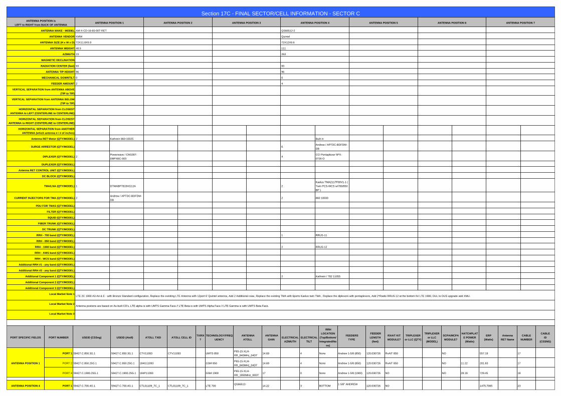
Section 17C - FINAL SECTOR/CELL INFORMATION - SECTOR CANTENNA POSITION is
LEFT to RIGHT from BACK OF ANTENNAANTENNA POSITION 1 ANTENNA POSITION 2 ANTENNA POSITION 3 ANTENNA POSITION 4 ANTENNA POSITION 5 ANTENNA POSITION 6 ANTENNA POSITION 7
ANTENNA MAKE - MODEL AM-X-CD-16-65-00T-RET QS66512-2
ANTENNA VENDOR KMW Quintel
ANTENNA SIZE (H x W x D) 72X11.8X5.9 72X12X9.6
ANTENNA WEIGHT 48.5 111
AZIMUTH 23 263
MAGNETIC DECLINATION
RADIATION CENTER (feet) 93 93
ANTENNA TIP HEIGHT 96 96
MECHANICAL DOWNTILT 0 0
FEEDER AMOUNT 2 4
VERTICAL SEPARATION from ANTENNA ABOVE
(TIP to TIP)
VERTICAL SEPARATION from ANTENNA BELOW
(TIP to TIP)
HORIZONTAL SEPARATION from CLOSEST
ANTENNA to LEFT (CENTERLINE to CENTERLINE)
HORIZONTAL SEPARATION from CLOSEST
ANTENNA to RIGHT (CENTERLINE to CENTERLINE)
HORIZONTAL SEPARATION from ANOTHER
ANTENNA (which antenna # / # of inches)
Antenna RET Motor (QTY/MODEL) 2 Kathrein 860-10025 Built in
SURGE ARRESTOR (QTY/MODEL) 6Andrew / APTDC-BDFDM-
DB
DIPLEXER (QTY/MODEL) 2Powerwave / CM1007-
DBPXBC-0034
CCI Pentaplexer 5PX-
0726-O
DUPLEXER (QTY/MODEL)
Antenna RET CONTROL UNIT (QTY/MODEL)
DC BLOCK (QTY/MODEL)
TMA/LNA (QTY/MODEL) 1 DTMABP7819VG12A 2
Kaelus TMA2117F00V1-1 (
Twin PCS-WCS w/700/850
BP )
CURRENT INJECTORS FOR TMA (QTY/MODEL) 2Andrew / APTDC-BDFDM-
DB2 860 10030
PDU FOR TMAS (QTY/MODEL)
FILTER (QTY/MODEL)
SQUID (QTY/MODEL)
FIBER TRUNK (QTY/MODEL)
DC TRUNK (QTY/MODEL)
RRH - 700 band (QTY/MODEL) 1 RRUS-11
RRH - 850 band (QTY/MODEL)
RRH - 1900 band (QTY/MODEL) 2 RRUS-12
RRH - AWS band (QTY/MODEL)
RRH - WCS band (QTY/MODEL)
Additional RRH #1 - any band (QTY/MODEL)
Additional RRH #2 - any band (QTY/MODEL)
Additional Component 1 (QTY/MODEL) 2 Kathrein / 782 11055
Additional Component 2 (QTY/MODEL)
Additional Component 3 (QTY/MODEL)
Local Market Note 1LTE 2C 1900 A3-A4 & E - with Bronze Standard configuration, Replace the exisiting LTE Antenna with 12port 6' Quintel antenna, Add 2 Additional coax, Replace the existing TMA with 6ports Kaelus twin TMA , Replace the diplexers with pentaplexers, Add 2*Radio RRUS-12 at the bottom for LTE 1900, DUL to DUS upgrade add XMU.
Local Market Note 2Antenna postions are based on As-built CD's, LTE alpha is with UMTS Gamma Face // LTE Beta is with UMTS Alpha Face // LTE Gamma is with UMTS Beta Face.
Local Market Note 3
a
PORT SPECIFIC FIELDS PORT NUMBER USEID (CSSng) USEID (Atoll) ATOLL TXID ATOLL CELL IDTX/RX
?
TECHNOLOGY/FREQ
UENCY
ANTENNA
ATOLL
ANTENNA
GAIN
ELECTRICAL
AZIMUTH
ELECTRICAL
TILT
RRH
LOCATION
(Top/Bottom/
Integrated/No
ne)
FEEDERS
TYPE
FEEDER
LENGTH
(feet)
RXAIT KIT
MODULE?
TRIPLEXER
or LLC (QTY)
TRIPLEXER
or LLC
(MODEL)
SCPA/MCPA
MODULE?
HATCHPLAT
E POWER
(Watts)
ERP
(Watts)
Antenna
RET Name
CABLE
NUMBER
CABLE
ID
(CSSNG)
ANTENNA POSITION 1
PORT 1 59427.C.850.3G.1 59427.C.850.3G.1 CTV11093 CTV11093 UMTS 850P65-15-XLH-
RR_840MHz_04DT14.69 4 None Andrew 1-5/8 (850) 120.030726 RxAIT 850 NO 557.19 17
PORT 2 59427.C.850.25G.1 59427.C.850.25G.1 184G11093 GSM 850P65-15-XLH-
RR_840MHz_04DT14.69 4 None Andrew 1-5/8 (850) 120.030726 RxAIT 850 NO 11.22 201.83 17
PORT 4 59427.C.1900.25G.1 59427.C.1900.25G.1 184P11093 GSM 1900P65-15-XLH-
RR_1950MHz_00DT17 0 None Andrew 1-5/8 (1900) 120.030726 NO NO 28.18 729.45 18
a
ANTENNA POSITION 4 PORT 1 59427.C.700.4G.1 59427.C.700.4G.1 CTL01109_7C_1 CTL01109_7C_1 LTE 700QS66512-
14.22 3 BOTTOM1 5/8" ANDREW
120.030726 NO 1475.7065 23

2_719MHz_03DT AVA7-50_700 MHz
PORT 3 59427.C.1900.4G.tmp1 59427.C.1900.4G.1 CTL01109_9C_1 CTL01109_9C_1 LTE 1900QS66512-
2_1930MHz_04DT17.14 4 BOTTOM
1 5/8" ANDREW
AVA7-50_700 MHz120.030726 NO 2421.029 23
PORT 459427.C.1900.4G.tmp1,59427
.C.1900.4G.tmp259427.C.1900.4G.1 CTL01109_9C_2 CTL01109_9C_2 LTE 1900
QS66512-
2_1930MHz_04DT17.14 4 BOTTOM
1 5/8" ANDREW
AVA7-50_700 MHz120.030726 NO 2421.029 23
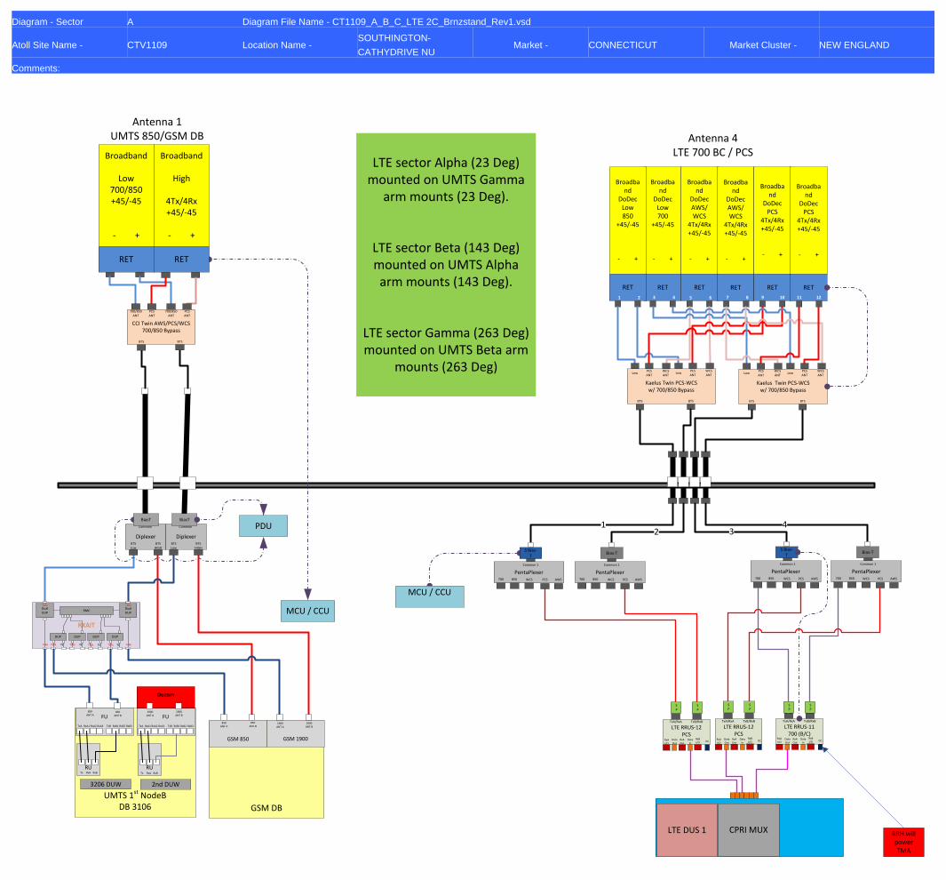
Diagram - Sector A Diagram File Name - CT1109_A_B_C_LTE 2C_Brnzstand_Rev1.vsd
Atoll Site Name - CTV1109 Location Name -SOUTHINGTON-
CATHYDRIVE NUMarket - CONNECTICUT Market Cluster - NEW ENGLAND
Comments:
Decom
Antenna 1UMTS 850/GSM DB
MCU / CCU
DiplexerBTS Low
Common
BTSHIGH
DiplexerBTS Low
Common
BTSHIGH
PDUBiasT BiasT
RXAIT
DualDUP
DualDUP
RMC
DUP DUP DUP DUP
TxRx TxRx TxRx TxRx TxRx TxRxTx Tx Tx Tx
TxRx TxRx
PentaPlexer850
Common 1
700 AWSPCSWCS
PentaPlexer850
Common 1
700 AWSPCSWCS
Antenna 4LTE 700 BC / PCS
Antenna 2
LTE RRUS-11700 (B/C)
TxA/RxA TxB/RxB
Data Out
RxA I/O
RxB I/O
RxA Out
Data In
DC
12 3
4
SP
SP
MCU / CCU
SP
SP
RRH will power TMA
LTE RRUS-12PCS
TxA/RxA TxB/RxB
Data Out
RxA I/O
RxB I/O
RxA Out
Data In
DC
Bias-TS Bias-
T
PentaPlexer850
Common 1
700 AWSPCSWCS
PentaPlexer850
Common 1
700 AWSPCSWCS
Bias-TS Bias-
T
Broadband
DoDecLow700
+45/-45
- +
Broadband
DoDecAWS/WCS
4Tx/4Rx+45/-45
- +
RET RET
Broadband
DoDecAWS/WCS
4Tx/4Rx+45/-45
- +
RET
Broadband
DoDecLow850
+45/-45
- +
RET
Broadband
DoDecPCS
4Tx/4Rx+45/-45
- +
RET
Broadband
DoDecPCS
4Tx/4Rx+45/-45
- +
RET
1 2 3 4 5 6 7 8 9 10 11 12
Kaelus Twin PCS-WCS w/ 700/850 Bypass
LowPCSANT
BTS
WCSANT
BTS
LowPCSANT
WCSANT
Kaelus Twin PCS-WCS w/ 700/850 Bypass
LowPCSANT
BTS
WCSANT
BTS
LowPCSANT
WCSANT
LTE DUS 1 CPRI MUX
SP
SP
LTE RRUS-12PCS
TxA/RxA TxB/RxB
Data Out
RxA I/O
RxB I/O
RxA Out
Data In
DC
GSM DB
GSM 850
850ANT A
850ANT B
GSM 1900
1900ANT A
1900ANT B
UMTS 1st NodeBDB 3106
FUFU850
ANT A1900
ANT A850
ANT B
1900ANT B
TxA RxA1 RxA2 RxA3 TxB RxB1 RxB2 RxB3 TxA RxA1 RxA2 RxA3 TxB RxB1
RUTx RxA RxB
RUTx RxA RxB
2nd DUW3206 DUW
RxB2 RxB3
Broadband
Low700/850+45/-45
- +
Broadband
High
4Tx/4Rx+45/-45
- +
RET RET
CCI Twin AWS/PCS/WCS700/850 Bypass
700/850ANT
PCSANT
BTS
700/850ANT
PCSANT
BTS
LTE sector Alpha (23 Deg)
mounted on UMTS Gamma arm mounts (23 Deg).
LTE sector Beta (143 Deg) mounted on UMTS Alpha arm mounts (143 Deg).
LTE sector Gamma (263 Deg) mounted on UMTS Beta arm
mounts (263 Deg)

Diagram - Sector B Diagram File Name - CT1109_A_B_C_LTE 2C_Brnzstand_Rev1.vsd
Atoll Site Name - CTV1109 Location Name -SOUTHINGTON-
CATHYDRIVE NUMarket - CONNECTICUT Market Cluster - NEW ENGLAND
Comments:
Decom
Antenna 1UMTS 850/GSM DB
MCU / CCU
DiplexerBTS Low
Common
BTSHIGH
DiplexerBTS Low
Common
BTSHIGH
PDUBiasT BiasT
RXAIT
DualDUP
DualDUP
RMC
DUP DUP DUP DUP
TxRx TxRx TxRx TxRx TxRx TxRxTx Tx Tx Tx
TxRx TxRx
PentaPlexer850
Common 1
700 AWSPCSWCS
PentaPlexer850
Common 1
700 AWSPCSWCS
Antenna 4LTE 700 BC / PCS
Antenna 2
LTE RRUS-11700 (B/C)
TxA/RxA TxB/RxB
Data Out
RxA I/O
RxB I/O
RxA Out
Data In
DC
12 3
4
SP
SP
MCU / CCU
SP
SP
RRH will power TMA
LTE RRUS-12PCS
TxA/RxA TxB/RxB
Data Out
RxA I/O
RxB I/O
RxA Out
Data In
DC
Bias-TS Bias-
T
PentaPlexer850
Common 1
700 AWSPCSWCS
PentaPlexer850
Common 1
700 AWSPCSWCS
Bias-TS Bias-
T
Broadband
DoDecLow700
+45/-45
- +
Broadband
DoDecAWS/WCS
4Tx/4Rx+45/-45
- +
RET RET
Broadband
DoDecAWS/WCS
4Tx/4Rx+45/-45
- +
RET
Broadband
DoDecLow850
+45/-45
- +
RET
Broadband
DoDecPCS
4Tx/4Rx+45/-45
- +
RET
Broadband
DoDecPCS
4Tx/4Rx+45/-45
- +
RET
1 2 3 4 5 6 7 8 9 10 11 12
Kaelus Twin PCS-WCS w/ 700/850 Bypass
LowPCSANT
BTS
WCSANT
BTS
LowPCSANT
WCSANT
Kaelus Twin PCS-WCS w/ 700/850 Bypass
LowPCSANT
BTS
WCSANT
BTS
LowPCSANT
WCSANT
LTE DUS 1 CPRI MUX
SP
SP
LTE RRUS-12PCS
TxA/RxA TxB/RxB
Data Out
RxA I/O
RxB I/O
RxA Out
Data In
DC
GSM DB
GSM 850
850ANT A
850ANT B
GSM 1900
1900ANT A
1900ANT B
UMTS 1st NodeBDB 3106
FUFU850
ANT A1900
ANT A850
ANT B
1900ANT B
TxA RxA1 RxA2 RxA3 TxB RxB1 RxB2 RxB3 TxA RxA1 RxA2 RxA3 TxB RxB1
RUTx RxA RxB
RUTx RxA RxB
2nd DUW3206 DUW
RxB2 RxB3
Broadband
Low700/850+45/-45
- +
Broadband
High
4Tx/4Rx+45/-45
- +
RET RET
CCI Twin AWS/PCS/WCS700/850 Bypass
700/850ANT
PCSANT
BTS
700/850ANT
PCSANT
BTS
LTE sector Alpha (23 Deg)
mounted on UMTS Gamma arm mounts (23 Deg).
LTE sector Beta (143 Deg) mounted on UMTS Alpha arm mounts (143 Deg).
LTE sector Gamma (263 Deg) mounted on UMTS Beta arm
mounts (263 Deg)

Diagram - Sector C Diagram File Name - CT1109_A_B_C_LTE 2C_Brnzstand_Rev1.vsd
Atoll Site Name - CTV1109 Location Name -SOUTHINGTON-
CATHYDRIVE NUMarket - CONNECTICUT Market Cluster - NEW ENGLAND
Comments:
Decom
Antenna 1UMTS 850/GSM DB
MCU / CCU
DiplexerBTS Low
Common
BTSHIGH
DiplexerBTS Low
Common
BTSHIGH
PDUBiasT BiasT
RXAIT
DualDUP
DualDUP
RMC
DUP DUP DUP DUP
TxRx TxRx TxRx TxRx TxRx TxRxTx Tx Tx Tx
TxRx TxRx
PentaPlexer850
Common 1
700 AWSPCSWCS
PentaPlexer850
Common 1
700 AWSPCSWCS
Antenna 4LTE 700 BC / PCS
Antenna 2
LTE RRUS-11700 (B/C)
TxA/RxA TxB/RxB
Data Out
RxA I/O
RxB I/O
RxA Out
Data In
DC
12 3
4
SP
SP
MCU / CCU
SP
SP
RRH will power TMA
LTE RRUS-12PCS
TxA/RxA TxB/RxB
Data Out
RxA I/O
RxB I/O
RxA Out
Data In
DC
Bias-TS Bias-
T
PentaPlexer850
Common 1
700 AWSPCSWCS
PentaPlexer850
Common 1
700 AWSPCSWCS
Bias-TS Bias-
T
Broadband
DoDecLow700
+45/-45
- +
Broadband
DoDecAWS/WCS
4Tx/4Rx+45/-45
- +
RET RET
Broadband
DoDecAWS/WCS
4Tx/4Rx+45/-45
- +
RET
Broadband
DoDecLow850
+45/-45
- +
RET
Broadband
DoDecPCS
4Tx/4Rx+45/-45
- +
RET
Broadband
DoDecPCS
4Tx/4Rx+45/-45
- +
RET
1 2 3 4 5 6 7 8 9 10 11 12
Kaelus Twin PCS-WCS w/ 700/850 Bypass
LowPCSANT
BTS
WCSANT
BTS
LowPCSANT
WCSANT
Kaelus Twin PCS-WCS w/ 700/850 Bypass
LowPCSANT
BTS
WCSANT
BTS
LowPCSANT
WCSANT
LTE DUS 1 CPRI MUX
SP
SP
LTE RRUS-12PCS
TxA/RxA TxB/RxB
Data Out
RxA I/O
RxB I/O
RxA Out
Data In
DC
GSM DB
GSM 850
850ANT A
850ANT B
GSM 1900
1900ANT A
1900ANT B
UMTS 1st NodeBDB 3106
FUFU850
ANT A1900
ANT A850
ANT B
1900ANT B
TxA RxA1 RxA2 RxA3 TxB RxB1 RxB2 RxB3 TxA RxA1 RxA2 RxA3 TxB RxB1
RUTx RxA RxB
RUTx RxA RxB
2nd DUW3206 DUW
RxB2 RxB3
Broadband
Low700/850+45/-45
- +
Broadband
High
4Tx/4Rx+45/-45
- +
RET RET
CCI Twin AWS/PCS/WCS700/850 Bypass
700/850ANT
PCSANT
BTS
700/850ANT
PCSANT
BTS
LTE sector Alpha (23 Deg)
mounted on UMTS Gamma arm mounts (23 Deg).
LTE sector Beta (143 Deg) mounted on UMTS Alpha arm mounts (143 Deg).
LTE sector Gamma (263 Deg) mounted on UMTS Beta arm
mounts (263 Deg)

WORKFLOW SUMMARY
DateFROM
State / Status
FROM
ATTUID
TO
State / Status
TO
ATTUIDOperation Comments
PACE
Status
09/20/2016 Preliminary In Progress mm093qPreliminary Submitted for
ApprovalRC475S Promote LTE Preliminary RFDS
09/22/2016Preliminary Submitted for
ApprovalRC475S Preliminary Approved BG144B Promote
12/20/2016 Preliminary Approved BG144B Final RF Approval OM636A Promote Needs Final
12/20/2016 Final RF Approval OM636A Final Approved BG144B Promote LTE Final RFDS
NER-RCTB-12-04166 MRCTB019775 SUCCESS
12/20/2016 11:21:09 AM
NER-RCTB-16-03448 FAILURE 12/20/2016
11:21:09 AM

QS66512-2
6ft 65o XXX MultiServTM 12-Port Antenna
2x698-806*MHz / 2x824-894MHz / 4x1850-1990MHz / 4x1695-1780+2110-2400MHz
Quintel Product Datasheet QS66512-2 (700-2400 6ft 65deg) Dec 2015 (Rev 2.4).docx
The Quintel MultiServ
TM Multiband 12 Port Antenna with patented QTilt™ technology uniquely delivers four independent services in a
single slim-line antenna. This enables existing antenna network sites to be upgraded constraint free to add new services such as LTE for 700, 850, PCS, AWS and WCS bands with the replacement of one antenna. The QS66512-2 also provides 4x1695-1780+2110-2400MHz & 4x1850-1990MHz ports as two side-by-side (CLA-2X) arrays, each set of 4 ports having independent tilt for connection to 2T4R/4T4R services.
1 Typical Performance across frequency and Downtilt. *Products Ordered after Jan 2016 will be 698-806MHz
Mechanical Characteristics
Dimensions L 72”(1828mm) x W 12”(304mm) x D 9.6”(245mm)
Weight (excl mounting brackets) 111lbs (50.3kg)
No. of Connectors 12x 4.3-10.0 DIN Female Long Neck
Max Wind Speed 150mph (67m/s)
Equivalent Flat Plate Area 2.96ft2 (0.275m
2)
Wind Load @160km/h (45m/s) Front: 587N (132 lbs), Side: 382N (86 lbs)
Operating Temperature -40°C to +65°C
Electrical Characteristics 2x Ports
1&2
2x Ports
3&4
4x Ports
5-8
4 Ports
9-12
Operating Frequency (MHz 698-806* 824-894 1695-1780 and 2110-2400 1850-1990
698-806 824-894 1695-1780 2110-2180 2300-2400 1850-1990
Azimuth beamwidth1 67
O 64
O 68
O 63
O 58
O 69
O
Elevation beamwidth1 12
O 10
O 6.5
O 5.5
O 4.5
O 5.5
O
Gain1
(dBi) 13.2 13.5 16.2 16.5 17.0 16.0
Polarization ±45
O
±45O
±45O
±45O
±45O
±45O
Electrical down-tilt range 2O-10
O 2
O-10
O 2
O – 7
O 2
O – 7
O
Upper SLL (20o > mainbeam)
1 -17dB -19dB -18dB -18B -18dB -16dB
Front to Back Ratio(180O±10
O)1 ≥27dB ≥29dB ≥28dB ≥28dB ≥28dB ≥27dB
Port to Port isolation1 ≥28dB ≥30dB ≥30dB ≥30dB ≥30dB ≥30dB
Return loss (VSWR) 14dB(1.5) 14dB(1.5) 14dB(1.5) 14dB(1.5) 14dB (1.5) 14dB(1.5)
X Polar Discrimination (at 0O) >18dB >16dB >20dB >20dB >18dB >20dB
Max Power handling (per any port) 500 watts 500 watts 250 watts 250 watts
Total Composite Power (all ports) 1750 watts
PIM (3rd
Order) (2x43dBm) >153dBc >153dBc >153dBc >153dBc
XBand PIM (3rd
Order) (2x43dBm) >159dBc
Fully Integrated RET Characteristics
AISG Standards V1.1,V 2.0 and 3GPP
Factory Default AISG 2.0
Surge immunity IEC 61000-4-5:2005 4KV(AISG PIN)
Device Type SRET Type 1
AISG Data rate 9.6 kbps
No of connectors 1in/1out.
Connector type IEC 60130-9 (Ed 3.0)
MTBF 36,000 Operational moves
Provides 12 antenna Ports in a slim-line form factor Optimized Azimuth patterns for Min Inter-Sector Interference Industry leading Minimal Wind-Load design
700, 850, PCS, AWS & WCS bands in one antenna AISG & 3GPP compliant internal remote electrical tilt (RET) AWS & PCS Cross band PIM >159dBc
All specifications are subject to change without notice. Please contact your Quintel representative for complete information.

www.kmwcomm.com
KMW Communications Base Station Antennas For Mobile Communications
AM-X-CD-16-65-00T-RET(6’ 65˚ Dual Broadband Antenna) Dual Band Electrical DownTilt Antenna
698 ~ 894MHz, X-pol., H65˚ / V12˚
1710 ~ 2170MHz, X-pol., H65˚ / V6.0˚
Electrical Specification Frequency Range 698~894MHz 1710~2170MHz
Impedance 50Ω
Polarization Dual, Slant ±45˚
Gain 15.5dBi / 13.35dBd @ 698-806MHz 16.0dBi / 13.85dBd @ 824-894MHz
17.3dBi / 15.15dBd @ 1710-1755MHz 17.4dBi / 15.25dBd @ 1850-1900MHz 17.1dBi / 14.95dBd @ 2110-2155MHz
Beamwidth
Horizontal 65˚ @ 698-806MHz 63˚ @ 824-894MHz
65˚ @ 1710-1755MHz 67˚ @ 1850-1900MHz 69˚ @ 2110-2155MHz
Vertical 12.3˚ @ 698-806MHz 11.5˚ @ 824-894MHz
6.5˚ @ 1710-1755MHz 6.0˚ @ 1850-1900MHz 5.7˚ @ 2110-2155MHz
VSWR ≤1.5:1
Front-to-Back Ratio ≥27 dB
Electrical Downtilt Range 2˚ ~ 16˚ 0˚ ~ 10˚
Isolation Between Ports ≥30 dB
Isolation Between Ports of Different Frequency Elements ≥35 dB
Cross Pole Discrimination 10.0 dB @ ±60˚ 15.0 dBi @ 0˚
First Upper Side Lobe Suppression 16dB
Side Lobe Suppression > 16 dB @ 0-6˚ Tilt > 18 dB @ 7-12˚ Tilt
(Up to 10˚ from Boresight)
> 16 dB @ 0-6˚ Tilt > 18 dB @ 7-10˚ Tilt
(Up to 10˚ from Boresight)
Passive Intermodulation ≤ -150 dBc @ 2x20w
Input Maximum CW Power 500 W 300 W
Environmental Compliance IP65 for Radome
IP67 for Connectors
RET Motor Configuration Field Replaceable RET Electronic Control Module /
RET Motor is internal to antenna & not field replaceable
Compliant with AISG 1.1 and 2.0 AISG 1.1 and 2.0
Mechanical Specification
300
Dimension (W×D×H) 11.8×5.9×72 inches (300×150×1829mm)
Weight (Without clamp) 48.5 lbs (22.0 kg)
Connector
4 x 7/16 DIN(F), Long Neck
Max Wind Speed 150 mph
Wind Load (@150 mph) 1891 N

Page 1 Revision 1.0
Technical Description
General Information CCI’s Twin Triple Band (700 Band, Cellular and PCS) TMA contains two triple band TMA’s in a single housing. The PCS TMA is full band and fully duplexed, while the 700 Band and Cellular RF is bypassed and combined (Diplexed) with the PCS RF signal. High linearity im-proves the uplink sensitivity and the receive performance of base stations. The TMA is fully compliant with the latest AISG 2.0 specification. The TMA supports EDGE/GSM, UMTS and LTE BTS equipment. It provides a convenient package for sites upgraded to triple or quad antenna con-figurations. The twin TMA package reduces tower loading, leasing, and installation costs. Unit count on the tower is cut in half. An excellent match for two branch receive di-versity applications using triple polarization antennas. The input and output connectors are located inline for ease of installation in space constrained areas such as uni-pole structures and stealth antennas.
General Info and Technical Description 1
Electrical & Mechanical Specs (AISG TMA) 2
Block Diagram & Outline Drawing (AISG TMA) 3
Contents:
The TMA system consists of a twin outdoor triple band tower mount unit which com-bine separate PCS, 700 Band & Cellular antennas onto a single BTS port. The PCS path of the tower mount unit is dual duplexed to separate the low-power uplink signals from the high-power downlink signals at the antenna port, amplifies the low-level uplink signals using an ultra-low noise amplifier (LNA), and recombines the two paths at the BTS port. The 700 Band & Cellular path is ultra low loss and passive. Both paths are diplexed at the BTS port. The tower mount units consist of eight band-pass filters, two redundant low-noise amplifiers, bypass failure circuitry, and bias tee’s which are all housed in an IP65 moisture proof enclosure, with IP68 Im-mersion proof connectors suited to long-life masthead mounting. The unit provides protection against lightning strikes via a multi-stage surge protection circuit. DC power and control is provided via the feeder cable from the BTS or a Power Distri-bution Unit (PDU). Optional AISG 2.0 DC power and control is provided via the feeder cable from the BTS using the AISG 2.0 and 3GPP standard. The optional AISG TMA detects which BTS port has DC Voltage/AISG Sampling applied and automatically switches to utilize that port. Additionally the AISG TMA operates at constant power when powered by an AISG 2.0 Compatible Site Control Unit, but may be powered by a “Standard Power distribution Unit. A separate AISG connector is also provided to allow direct AISG connection or “Daisy Chaining” to multiple AISG products at the top of the tower.
An optional indoor site control unit (SCU) is available to power up to up to 32 AISG modules per sector and to provide the all the monitoring and alarm functions for the system. The SCU is housed in a single (1U) 1.75” x 19” rack and contains triple redundant power supplies capable of being “hot swapped” that provide a regulated DC supply voltage on the RF coax for the tower mount amplifiers.
Features:
Small, lightweight, twin unit
Triple Band Dual Du-plexed (PCS with 700 Band & Cellular Bypass)
Optional AISG 2.0 com-patible unit
AISG TMA detects BTS port that DC voltage and AISG sampling is applied to, and automatically switches to utilize that port
AISG TMA operates at constant power
AISG TMA may be pow-ered by a standard PDU
High linearity Lightning protected Fail-safe bypass mode High reliability
Twin Triple Band “Active PCS with 700 and 850 Band Pass-thru” Dual Duplexed TMA
Model DTMABP7819VG12A
Tel: 201-342-3338 Fax: 201-342-3339 www.cciproducts.com
CCI Confidential

Page 2 Revision 1.0
Twin Triple Band “Active AWS with 700 and 850 Band Pass-thru” TMA Typical Specifications
Communication Components Inc. Twin Triple Band “Active PCS with 700 and 850 Band Pass-thru” Dual Duplexed TMA
C o m m u n i c a t i o n C o m p o n e n t s I n c . Tel: 201-342-3338 Fax: 201-342-3339 CCI Confidential
Description Typical Specifications Electrical Specifications
700 Band & Cellular Frequency Range 698 to 894 MHz PCS Receive Frequency Range 1850 – 1910 MHz PCS Transmit Frequency Range 1930 - 1990 MHz PCS Amplifier Gain 6 to 12 dB Adjustable in 0.25 dB steps via AISG PCS Gain Variation ±1.0 dB
PCS System Noise Figure 1.4 dB (@ +25°C),1.6 dB (@ +65°C), At 1910 MHz: 1.7 dB (@ +25°C), 1.9 dB (@ +65°C)
PCS Input Third Order Intercept Point +12 dBm Min @ Max. Gain Input/Output Return Loss 18 dB Min. all ports, 15 dB Min. Bypass Mode Insertion Loss
700 Band & Cellular Passband < 0.2 dB, 0.1 dB typical PCS Transmit Passband 0.4 dB Typical PCS Transmit Passband Ripple ±0.2 dB
PCS Bypass Mode, Rx Passband 1.6 dB (@ +25°C),1.8 dB (@ +65°C), At 1910 MHz: 2.3 dB (@ +25°C), 2.5 dB (@ +65°C)
PCS Bypass Mode, Rx Passband Ripple ±1 dB Filter Characteristics
700 Band & Cellular Path Rejection 70 dB @ 1850 - 1990 MHz PCS Path Rejection 80 dB @ 698 - 894 MHz Continuous Average Power 200 Watts max Peak Envelope Power 2 kW max Intermodulation Performance
IMD at ANT port in Rx Band -112 dBm Min. (2 x +43 dBm tones) Operating Voltage +10V to +30V DC provided via coax or AISG Power Consumption ≤ 2.1 Watts
Mechanical Specifications Connectors DIN 7-16 Female (Long Neck) x 6, AISG x 1 Dimensions (Body Only) 10.63” (H) x 11.02” (W) x 3.78” (D); (270 (H) x 280 (W) x 96 (D) mm)
Weight (w/o Bracket) 19.18 Lbs. (8.7 Kg) Mounting Pole/Wall Mounting Bracket
Environmental Specifications Operating Temperature -40˚ C to +65˚C Lightning Protection 8/20us, ±2KA max, 10 strikes each, IEC61000-4-5 Enclosure IP65 (Unit Body), IP68 (Connector)
MTBF >500,000 hours
Dimensions (with Bracket) 14.25” (H) x 11.46” (W) x 4.17” (D); (362 (H) x 291 (W) x 106 (D) mm)
All specifications are subject to change. The latest specifications are available at www.cciproducts.com

TMA2117F00V1-1PCS / WCS Dual Band Twin TMA, with 700/850 bypass, AISG2.0
Designed to be deployed in co-located PCS & WCS systems with wideband antennas, the Kaelus TMA
provides internal diplexing and gain in both bands while allowing 700/850 services to pass through to a
separate antenna, thereby saving hardware costs.
PRODUCT FEATURES
Improved base station sensitivity through gain in PCS and WCS bands
Hardware and software configuration using AISG “Personality” upload
High Linearity and low noise performance; Bypass provided for 700/850MHz services
Fail safe bypass mode with lightning protection
TECHNICAL SPECIFICATIONSDownlink Path, Band 1 PCS
Passband 1930 - 1990
Insertion Loss 0.5dB typ
Return Loss 18dB min
Max Average input power (W) 160
Max PEP Input Power (W) 2000
Intermodulation, 2 x 43dBm TX carriers (dBc) -153dBc max
Uplink Path, Band 1
Passband 1850 - 1910
Gain (dB) 3dB to 13dB in 1dB steps
Gain window +/- 1dB max
Return Loss (Operating) 18dB min
Return Loss (Bypass) 12dB min
Noise Figure 1.4dB typ
Bypass Loss 2.5dB typ
| 1 |
© 2016 Kaelus Inc. All Rights Reserved. TMA2117F00V1-1www.kaelus.com
Revised 25 MAR 15

Output IP3 +30dBm typ
Maximum input power with no damage +12dBm max
Downlink Path, Band 2 WCS
Passband 2350 - 2360
Insertion Loss 0.5dB typ
Return Loss 18dB min
Max Average input power (W) 120
Max PEP Input Power (W) 1200
Intermodulation, 2 x 43dBm TX carriers (dBc) -153dBc max
Uplink Path, Band 2
Passband 2305 - 2315
Gain (dB) 2dB to 12dB in 1dB steps
Gain window +/- 1dB max
Return Loss (dB Min, Operating) 18
Return Loss (dB Min Bypass) 12
Noise Figure 1.7dB typ
Rejection @ Freq x (dBc Min) 2324.54 - 2341.285MHz (27.5dB min)
Bypass (Insertion) Loss 3.3dB typ
Output IP3 +30dBm typ
Maximum input power with no damage +12dBm max
Bypass Passband 698 – 896MHz
Insertion Loss 0.35dB typ
Return loss, all ports 18dB min
Continuous average power 200
Peak envelope power 2000
Intermodulation @ antenna port -153dBc max
CURRENT ALARM MODE (DEFAULT MODE SELECTED ON THEABSENCE OF AISG PACKETS)
DC Supply Voltage (VDC min) 8.5
DC Supply Voltage (VDC max) 30
Supply Current, Normal operation 250 +/- 20mA per port (programmable)
| 2 |
© 2016 Kaelus Inc. All Rights Reserved. TMA2117F00V1-1www.kaelus.com
Revised 25 MAR 15

Supply Current, alarm mode 320 +/- 30mA per port (programmable)
AISG MODE OF OPERATION (AUTO SELECTED ON VALID AISG 2.0FRAMES)
AISG Version 2
AISG Supply Current 400mA @ 8.5V, 120mA @ 30V typical
AISG Connector IEC60130-9, 8-pin female
AISG Connector Current rating < 4A peak, 2A continuous, pin 6
Field firmware upgradable Yes
ENVIRONMENTALTemperature range -40ºC to +65ºC | -40º to +149ºF
Environmental sealing IP67
Lightning protectionRF port: +/- 5kA max (8/20us), AISG port: +/- 2kA max (8/20us)
IEC61312-1
MTBF >1,000,000 hours
Compliance EMC:EN301 489, Ingress ETSI EN 300 019 class 4.1, RoHS
MECHANICALConnectors DIN 4.3-10 (F) x 8 long shank, AISG (F) x 1
Dimensions, H x D x W 216 x 300 x 107mm | 8.46 x 11.81 x 4.21in
Finish Powder coated, light grey (RAL7035)
Weight 8 kg | 17.6lbs est
MountingPole / wall bracket supplied with two metal clamps for 45-178
mm diameter poles
ELECTRICAL BLOCK DIAGRAM
| 3 |
© 2016 Kaelus Inc. All Rights Reserved. TMA2117F00V1-1www.kaelus.com
Revised 25 MAR 15

Centerline Communications, LLC 95 Ryan Drive, Suite 1 Raynham MA 02767
Radio Frequency Emissions Analysis Report
AT&T Existing Facility
Site ID: CT1109
Southington - Cathy Drive NU Cathy Drive
Southington, CT 6489
May 12, 2017
Centerline Communications Project Number: 950006-053
Site Compliance Summary
Compliance Status: COMPLIANT
Site total MPE% of FCC general population
allowable limit: 6.56 %

Centerline Communications, LLC 95 Ryan Drive, Suite 1 Raynham MA 02767
May 12, 2017
AT&T Mobility – New England Attn: John Benedetto, RF Manager 550 Cochituate Road Suite 550 – 13&14 Framingham, MA 06040
Emissions Analysis for Site: CT1109 – Southington - Cathy Drive NU
Centerline Communications, LLC (“Centerline”) was directed to analyze the proposed AT&T facility located at Cathy Drive, Southington, CT, for the purpose of determining whether the emissions from the Proposed AT&T Antenna Installation located on this property are within specified federal limits.
All information used in this report was analyzed as a percentage of current Maximum Permissible Exposure (% MPE) as listed in the FCC OET Bulletin 65 Edition 97-01and ANSI/IEEE Std C95.1. The FCC regulates Maximum Permissible Exposure in units of microwatts per square centimeter (µW/cm2). The number of µW/cm2 calculated at each sample point is called the power density. The exposure limit for power density varies depending upon the frequencies being utilized. Wireless Carriers and Paging Services use different frequency bands each with different exposure limits, therefore it is necessary to report results and limits in terms of percent MPE rather than power density.
All results were compared to the FCC (Federal Communications Commission) radio frequency exposure rules, 47 CFR 1.1307(b)(1) – (b)(3), to determine compliance with the Maximum Permissible Exposure (MPE) limits for General Population/Uncontrolled environments as defined below.
General population/uncontrolled exposure limits apply to situations in which the general population may be exposed or in which persons who are exposed as a consequence of their employment may not be made fully aware of the potential for exposure or cannot exercise control over their exposure. Therefore, members of the general population would always be considered under this category when exposure is not employment related, for example, in the case of a telecommunications facility that exposes persons in a nearby residential area.
Population exposure to radio frequencies is regulated and enforced in units of microwatts per square centimeter (μW/cm2). The general population exposure limits for the 700 and 850 MHz Bands are approximately 467 μW/cm2 and 567 μW/cm2 respectively. The general population exposure limit for the 1900 MHz (PCS), 2100 MHz (AWS) and 2300 MHz (WCS) bands is 1000 μW/cm2. Because each carrier will be using different frequency bands, and each frequency band has different exposure limits, it is necessary to report percent of MPE rather than power density.

Centerline Communications, LLC 95 Ryan Drive, Suite 1 Raynham MA 02767
Occupational/controlled exposure limits apply to situations in which persons are exposed as a consequence of their employment and in which those persons who are exposed have been made fully aware of the potential for exposure and can exercise control over their exposure. Occupational/controlled exposure limits also apply where exposure is of a transient nature as a result of incidental passage through a location where exposure levels may be above general population/uncontrolled limits (see below), as long as the exposed person has been made fully aware of the potential for exposure and can exercise control over his or her exposure by leaving the area or by some other appropriate means.
Additional details can be found in FCC OET 65.

Centerline Communications, LLC 95 Ryan Drive, Suite 1 Raynham MA 02767
CALCULATIONS
Calculations were performed for the proposed AT&T Wireless antenna facility located at Cathy Drive, Southington, CT, using the equipment information listed below. All calculations were performed per the specifications under FCC OET 65. Since AT&T is proposing highly focused directional panel antennas, which project most of the emitted energy out toward the horizon, all calculations were performed assuming a lobe representing the maximum gain of the antenna per the antenna manufactures supplied specifications, minus 10 dB, was focused at the base of the utility transmission tower. For this report the sample point is the top of a 6-foot person standing at the base of the utility transmission tower.
Per FCC OET Bulletin No. 65 - Edition 97-01 recommendations to achieve the maximum anticipated value at each sample point, all power levels emitting from the proposed antenna installation are increased by a factor of 2.56 to account for possible in-phase reflections from the surrounding environment. All power values expressed and analyzed are maximum power levels expected to be used on all radios.
All emissions values for additional carriers were taken from the Connecticut Siting Council (CSC) active MPE database. Values in this database are provided by the individual carriers themselves
For each sector the following channel counts, frequency bands and power levels were utilized as shown in Table 1:
Technology Frequency Band Channel Count Transmit Power per
Channel (W) UMTS 850 MHz 2 30 GSM 850 MHz 2 30 GSM 1900 MHz (PCS) 2 30 LTE 700 MHz 2 60 LTE 1900 MHz (PCS) 2 60
Table 1: Channel Data Table

Centerline Communications, LLC 95 Ryan Drive, Suite 1 Raynham MA 02767
The following antennas listed in Table 2 were used in the modeling for transmission in the 700 MHz, 850 MHz and 1900 MHz (PCS) frequency bands. This is based on feedback from the carrier with regards to anticipated antenna selection. Maximum gain values for all antennas are listed in the Inventory and Power Data table below. The maximum gain of the antenna per the antenna manufactures supplied specifications, minus 10 dB, was used for all calculations. This value is a very conservative estimate as gain reductions for these particular antennas are typically much higher in this direction.
Sector Antenna Number Antenna Make / Model
Antenna Centerline
(ft) A 1 KMW AM-X-CD-16-65-00T-RET 91 A 2 Quintel QS66512-2 91 B 1 KMW AM-X-CD-16-65-00T-RET 91 B 2 Quintel QS66512-2 91 C 1 KMW AM-X-CD-16-65-00T-RET 91 C 2 Quintel QS66512-2 91
Table 2: Antenna Data
All calculations were done with respect to uncontrolled / general population threshold limits.

Centerline Communications, LLC 95 Ryan Drive, Suite 1 Raynham MA 02767
RESULTS
Per the calculations completed for the proposed AT&T configurations Table 3 shows resulting emissions power levels and percentages of the FCC’s allowable general population limit.
Antenna ID Antenna Make / Model Frequency Bands
Antenna Gain (dBd)
Channel Count
Total TX
Power (W) ERP (W) MPE %
Antenna A1
KMW AM-X-CD-16-65-00T-RET
850 MHz / 1900 MHz (PCS)
13.85 / 15.25 6 180 4,921.72 3.56
Antenna A2 Quintel QS66512-2
700 MHz / 1900 MHz (PCS)
10.85 / 13.85 4 240 4,371.36 3.00
Sector A Composite MPE% 6.56 Antenna
B1 KMW AM-X-CD-16-65-
00T-RET 850 MHz /
1900 MHz (PCS) 13.85 / 15.25 6 180 4,921.72 3.56
Antenna B2 Quintel QS66512-2
700 MHz / 1900 MHz (PCS)
10.85 / 13.85 4 240 4,371.36 3.00
Sector B Composite MPE% 6.56 Antenna
C1 KMW AM-X-CD-16-65-
00T-RET 850 MHz /
1900 MHz (PCS) 13.85 / 15.25 6 180 4,921.72 3.56
Antenna C2 Quintel QS66512-2
700 MHz / 1900 MHz (PCS)
10.85 / 13.85 4 240 4,371.36 3.00
Sector C Composite MPE% 6.56 Table 3: AT&T Emissions Levels

Centerline Communications, LLC 95 Ryan Drive, Suite 1 Raynham MA 02767
The Following table (table 4) shows all additional carriers on site and their MPE% as recorded in the CSC active MPE database for this facility along with the newly calculated maximum AT&T MPE contributions per this report. FCC OET 65 specifies that for carriers utilizing directional antennas that the highest recorded sector value be used for composite site MPE values due to their greatly reduced emissions contributions in the directions of the adjacent sectors. For this site, all three sectors have the same configuration yielding the same results on all three sectors. Table 5 below shows a summary for each AT&T Sector as well as the composite MPE value for the site.
Table 4: All Carrier MPE Contributions
Table 5: Site MPE Summary
Site Composite MPE% Carrier MPE%
AT&T – Max Sector Value 6.56 % No Additional Carriers Present at This Facility NA
Site Total MPE %: 6.56 %
AT&T Sector A Total: 6.56 % AT&T Sector B Total: 6.56 % AT&T Sector C Total: 6.56 %
Site Total: 6.56 %

Centerline Communications, LLC 95 Ryan Drive, Suite 1 Raynham MA 02767
FCC OET 65 specifies that for carriers utilizing directional antennas that the highest recorded sector value be used for composite site MPE values due to their greatly reduced emissions contributions in the directions of the adjacent sectors. Table 6 below details a breakdown by frequency band and technology for the MPE power values for the maximum calculated AT&T sector(s). For this site, all three sectors have the same configuration yielding the same results on all three sectors.
Table 6: AT&T Maximum Sector MPE Power Values
AT&T _ Frequency Band / Technology (All Sectors)
# Channels
Watts ERP (Per Channel)
Height (feet)
Total Power Density
(µW/cm2) Frequency (MHz)
Allowable MPE
(µW/cm2)
Calculated % MPE
AT&T 850 MHz UMTS 2 727.98 91 7.24 850 MHz 567 1.28% AT&T 850 MHz GSM 2 727.98 91 7.24 850 MHz 567 1.28%
AT&T 1900 MHz (PCS) GSM 2 1,004.90 91 10.00 1900 MHz (PCS) 1000 1.00% AT&T 700 MHz LTE 2 729.71 91 7.26 700 MHz 467 1.56%
AT&T 1900 MHz (PCS) LTE 2 1,455.97 91 14.49 1900 MHz (PCS) 1000 1.45% Total: 6.56%

Centerline Communications, LLC 95 Ryan Drive, Suite 1 Raynham MA 02767
Summary
All calculations performed for this analysis yielded results that were within the allowable limits for general population exposure to RF Emissions.
The anticipated maximum composite contributions from the AT&T facility as well as the site composite emissions value with regards to compliance with FCC’s allowable limits for general population exposure to RF Emissions are shown here:
AT&T Sector Power Density Value (%) Sector A: 6.56 % Sector B: 6.56 % Sector C: 6.56 %
AT&T Maximum Total (per sector): 6.56 %
Site Total: 6.56 %
Site Compliance Status: COMPLIANT
The anticipated composite MPE value for this site assuming all carriers present is 6.56 % of the allowable FCC established general population limit sampled at the ground level. This is based upon values listed in the Connecticut Siting Council database for existing carrier emissions.
FCC guidelines state that if a site is found to be out of compliance (over allowable thresholds), that carriers over a 5% contribution to the composite value will require measures to bring the site into compliance. For this facility, the composite values calculated were well within the allowable 100% threshold standard per the federal government.
Scott Heffernan RF Engineering Director Centerline Communications, LLC 95 Ryan Drive, Suite 1 Raynham, MA 02767