Embed Size (px)
Citation preview

TMA Q Series Getting Started Guide 1
Q SeriesGetting Started Guide
TMAThermomechanical
Analyzer
Revision DIssued November 2006

TMA Q Series Getting Started Guide2
©2003, 2004 by TA Instruments—Waters LLC109 Lukens DriveNew Castle, DE 19720
Notice
The material contained in this manual, and in the online help for the software used to support this instrument,is believed adequate for the intended use of the instrument. If the instrument or procedures are used for pur-poses other than those specified herein, confirmation of their suitability must be obtained from TA Instruments.Otherwise, TA Instruments does not guarantee any results and assumes no obligation or liability. TA Instru-ments also reserves the right to revise this document and to make changes without notice.
TA Instruments may have patents, patent applications, trademarks, copyrights, or other intellectual propertycovering subject matter in this document. Except as expressly provided in written license agreement from TAInstrument, the furnishing of this document does not give you any license to these patents, trademarks, copy-rights, or other intellectual property.
TA Instruments Operating Software, as well as Module, Data Analysis, and Utility Software and their associ-ated manuals and online help, are proprietary and copyrighted by TA Instruments. Purchasers are granted alicense to use these software programs on the module and controller with which they were purchased. Theseprograms may not be duplicated by the purchaser without the prior written consent of TA Instruments. Eachlicensed program shall remain the exclusive property of TA Instruments, and no rights or licenses are granted tothe purchaser other than as specified above.

TMA Q Series Getting Started Guide 3
Important: TA Instruments Manual SupplementPlease click on the links below to access important information supplemental to thisGetting Started Guide:
• TA Instruments Trademarks
• TA Instruments Patents
• Other Trademarks
• TA Instruments End-User License Agreement
• TA Instruments Offices
TMA Q Series Getting Started Guide4
Important: TA Instruments Manual Supplement ........................................................................................................ 3
Table of Contents ............................................................................................................................................................. 4
Notes, Cautions, and Warnings .................................................................................................................................... 6
Regulatory Compliance .................................................................................................................................................. 7Safety Standards ...................................................................................................................................................... 7Electromagnetic Compatibility Standards ............................................................................................................ 7
Safety ................................................................................................................................................................................. 8Instrument Symbols ................................................................................................................................................. 8Electrical Safety ........................................................................................................................................................ 8Sample Decomposition ............................................................................................................................................ 9Lifting the Instrument .............................................................................................................................................. 9Handling Liquid Nitrogen ...................................................................................................................................... 9Thermal Safety ........................................................................................................................................................ 10Cleaning the Instrument ........................................................................................................................................ 10
Chapter 1: Introducing the TMA ............................................................................................................................... 11
Overview ........................................................................................................................................................................ 11
TMA System Components ............................................................................................................................................ 11Standard Accessories ............................................................................................................................................ 12Subambient Operation ........................................................................................................................................... 12
The QTMA Touch Screen with QNX/PlatinumTM .............................................................................................................................................................................. 13QNX/Platinum Primary Function Keys ............................................................................................................. 13QNX/Platinum Control Menu ............................................................................................................................. 14QNX/Platinum Display Touch Screen Options ................................................................................................. 16QNX/Platinum Calibration Options ................................................................................................................... 17
The TMA Touch Screen (Original) ............................................................................................................................... 18Primary Function Keys .......................................................................................................................................... 18TMA Control Menu Keys ....................................................................................................................................... 19Display Menu Keys ................................................................................................................................................ 20
Options and Accessories .............................................................................................................................................. 21Probes ...................................................................................................................................................................... 21Mechanical Cooling Accessory ............................................................................................................................ 21
Instrument Specifications ............................................................................................................................................. 22TMA Instrument Characteristics ................................................................................................................... 22
Chapter 2: Installing the TMA ................................................................................................................................... 23
Unpacking/Repacking the TMA ................................................................................................................................ 23
Installing the Instrument .............................................................................................................................................. 23Inspecting the System ............................................................................................................................................ 23Choosing a Location .............................................................................................................................................. 24Voltage Configuration Unit ................................................................................................................................... 25
Table of Contents

TMA Q Series Getting Started Guide 5
Connecting Cables and Lines ............................................................................................................................... 26Ports .................................................................................................................................................................. 26Purge Line ........................................................................................................................................................ 27Connecting the Cooling Gas Line ................................................................................................................. 28
Installing the Stage ................................................................................................................................................. 29Installing the Expansion/Penetration Probes .................................................................................................... 30
Installing a Probe ............................................................................................................................................ 30Removing a Probe ........................................................................................................................................... 30Ethernet Switch Setup .................................................................................................................................... 31
Connecting the Instrument to the Switch .............................................................................................. 31Connecting the Controller to the Switch ............................................................................................... 31Connecting the Controller to a LAN ...................................................................................................... 32
Power Switch .......................................................................................................................................................... 33Power Cable ............................................................................................................................................................ 33
Starting the TMA ........................................................................................................................................................... 34
Shutting Down the TMA .............................................................................................................................................. 34
Chapter 3: Use, Maintenance, & Diagnostics .......................................................................................................... 35
Using the TMA .............................................................................................................................................................. 35Before You Begin .................................................................................................................................................... 35
Calibrating the TMA ..................................................................................................................................................... 36Force Calibration .................................................................................................................................................... 36Probe Calibration ................................................................................................................................................... 36Temperature Calibration ....................................................................................................................................... 36Cell Constant .......................................................................................................................................................... 37
Running a TMA Experiment ........................................................................................................................................ 38Selecting a Probe .................................................................................................................................................... 38Zeroing the Auto Measure System ....................................................................................................................... 39Guidelines for Handling Samples ....................................................................................................................... 40
Sample Preparation ........................................................................................................................................ 40Sample Loading .............................................................................................................................................. 40
Starting an Experiment .......................................................................................................................................... 41Stopping an Experiment ........................................................................................................................................ 41
Maintaining the Instrument ......................................................................................................................................... 42Cleaning the Touch Screen .................................................................................................................................... 42Cleaning the Probe Assembly ............................................................................................................................... 42Cleaning the Stage ................................................................................................................................................. 43Cleaning the Thermocouple .................................................................................................................................. 44
Replacements ................................................................................................................................................................. 45Replacing the Thermocouple ................................................................................................................................ 45
Removing the Existing Thermocouple ......................................................................................................... 45Installing a New Thermocouple ................................................................................................................... 45
Replacing Fuses ..................................................................................................................................................... 47Replacing the TMA Fuses .............................................................................................................................. 47
Replacement Parts ......................................................................................................................................................... 48
Index ............................................................................................................................................................................... 51

TMA Q Series Getting Started Guide6
Notes, Cautions, and Warnings
This manual uses NOTES, CAUTIONS, and WARNINGS to emphasize important and critical instructions.
A NOTE highlights important information about equipment or procedures.
A CAUTION emphasizes a procedure that may damage equipment or cause loss ofdata if not followed correctly.
A WARNING indicates a procedure that may be hazardous to the operator or to theenvironment if not followed correctly.
TMA Q Series Getting Started Guide 7
Regulatory ComplianceSafety StandardsFor Canada:
CAN/CSA-22.2 No. 1010.1-92 Safety requirements for electrical equipment for measurement, control, andlaboratory use, Part 1: General Requirements + Amendments.CAN/CSA-22.2 No. 1010.2.010-94 Particular requirements for laboratory equipment for the heating of materials+ Amendments.
For the European Economic Area: (In accordance with Council Directive 73/23/EEC of 19 February 1973 on theharmonization of the laws of Member States relating to electrical equipment designed for use within certainvoltage limits.)
EN61010-1: 1993 Safety requirements for electrical equipment for measurement, control, and laboratory use, Part1: General Requirements + Amendments.EN61010-2-010: 1994 Particular requirements for laboratory equipment for the heating of materials + Amend-ments.
For the United States:
UL61010A-1 Electrical Equipment for Laboratory Use; Part 1: General Requirements.IEC 1010-2-010: 1992 Particular requirements for laboratory equipment for the heating of materials + Amend-ments.
Electromagnetic Compatibility StandardsFor Australia and New Zealand:
AS/NZS 2064: 1997 Limits and methods of measurement of electronic disturbance characteristics of industrial,scientific and medical (ISM) radiofrequency equipment.
For Canada:
ICES-001 Issue 3 March 7, 1998 Interference-Causing Equipment Standard: Industrial, Scientific, and MedicalRadio Frequency Generators.
For the European Economic Area: (In accordance with Council Directive 89/336/EEC of 3 May 1989 on theapproximation of the laws of the Member States relating to electromagnetic compatibility.)
EN61326-1: 1997 Electrical equipment for measurement, control, andlaboratory use-EMC requirements-Part 1: General Requirements + Amendments. Emissions: Meets Class Arequirements (Table 3). Immunity: Meets performance criteria B for non-continuous operation, minimumrequirements (Table 1).
For the United States:
CFR Title 47 Telecommunication Chapter I Federal Communications Commission, Part 15 Radio frequencydevices (FCC regulation pertaining to radiofrequency emissions).
TMA Q Series Getting Started Guide8
SafetyCAUTION: The operator of this instrument is advised that if the equipment is used in amanner not specified in this manual, the protection provided by the equipment maybe impaired.
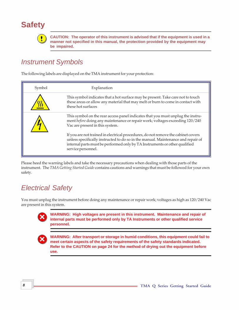
Instrument SymbolsThe following labels are displayed on the TMA instrument for your protection:
Symbol Explanation
This symbol indicates that a hot surface may be present. Take care not to touchthese areas or allow any material that may melt or burn to come in contact withthese hot surfaces
This symbol on the rear access panel indicates that you must unplug the instru-ment before doing any maintenance or repair work; voltages exceeding 120/240Vac are present in this system.
If you are not trained in electrical procedures, do not remove the cabinet coversunless specifically instructed to do so in the manual. Maintenance and repair ofinternal parts must be performed only by TA Instruments or other qualifiedservice personnel.
Please heed the warning labels and take the necessary precautions when dealing with those parts of theinstrument. The TMA Getting Started Guide contains cautions and warnings that must be followed for your ownsafety.
Electrical SafetyYou must unplug the instrument before doing any maintenance or repair work; voltages as high as 120/240 Vacare present in this system.
WARNING: High voltages are present in this instrument. Maintenance and repair ofinternal parts must be performed only by TA Instruments or other qualified servicepersonnel.
WARNING: After transport or storage in humid conditions, this equipment could fail tomeet certain aspects of the safety requirements of the safety standards indicated.Refer to the CAUTION on page 24 for the method of drying out the equipment beforeuse.

TMA Q Series Getting Started Guide 9
Sample DecompositionThe TMA is capable of heating samples to 1000°C. Many materials may decompose during the heating, whichcan generate hazardous byproducts.
WARNING: If you are using samples that may emit harmful gases, vent the gases byplacing the instrument near an exhaust.
Samples should not be heated above their decomposition temperatures to prevent the relase of hazardousmaterials or contamination of the TMA.
Lifting the InstrumentThe TMA is a fairly heavy instrument. In order to avoid injury, particularly to the back, please follow thisadvice:
WARNING: Close the furnace before moving the instrument, even for a short distance.Use two people to lift and/or carry the instrument. The instrument is too heavy for oneperson to handle safely.
Handling Liquid NitrogenThe TMA can use the cryogenic (low-temperature) agent, liquid nitrogen, for cooling in subambient experiments.Because of its low temperature [-195°C (-319°F)], liquid nitrogen will burn the skin. When you work with liquidnitrogen, use the following precautions:
WARNING: Liquid nitrogen boils rapidly when exposed to room temperature. Becertain that areas where liquid nitrogen is used are well ventilated to prevent dis-placement of oxygen in the air.
1. Wear goggles or a face shield, gloves large enough to be removed easily, and a rubber apron. For extraprotection, wear high-topped, sturdy shoes, and leave your pant legs outside the tops.
2. Transfer the liquid slowly to prevent thermal shock to the equipment. Use containers that have satisfactorylow-temperature properties. Ensure that closed containers have vents to relieve pressure.
3. The purity of liquid nitrogen decreases when exposed to air. If the liquid in a container has been open to theatmosphere for a prolonged period, analyze the remaining liquid before using it for any purpose where highoxygen content could be dangerous.

TMA Q Series Getting Started Guide10
WARNING:Potential Asphyxiant
Liquid nitrogen can cause rapid suffocation without warning.
Store and use in an area with adequate ventilation.
Do not enter confined spaces where nitrogen gas may be present unless thearea is well ventilated.
The warning above applies to the use of liquid nitrogen. Oxygen depletion sensors are sometimes utilizedwhere liquid nitrogen is in use.
Thermal SafetyDuring an experiment, the furnace and sample can become very hot or very cold to the touch.
WARNING: Do not use your hands to manually move the furnace and do not put yourhands up inside the furnace. It may be hot enough to cause burns.
Cleaning the InstrumentSee Chapter 3 for recommended cleaning and maintenance of the TMA instrument.
CAUTION: Before using any cleaning or decontamination method except thoserecommended by TA Instruments, please check with TA Instruments to make sure thatthe proposed method will not damage the equipment.

TMA Q Series Getting Started Guide 11
OverviewThe Thermomechanical Analyzer (TMA) is an analytical instrumentused to test the physical properties of many different materials.
The TMA instrument works in conjunction with a controller andassociated software to make up a thermal analysis system.
Your controller is a computer that performs the following functions:
• Provides an interface between you and the analysis instruments
• Enables you to set up experiments and enter constants• Stores experimental data• Runs data analysis programs.
NOTE: For technical reference information, theory ofoperation, and other information associated with theTMA and not found in this manual, see the online helpassociated with the instrument control software.
TMA System ComponentsYour instrument consists of the followingcomponents (see the figure here).
• The balance enclosure surrounds the TMAbalance mechanism, which exerts aspecified force on the sample.
• The probe assembly is inter-changeable formaking several different measurements onvarious sample materials.
• The stage is an interchangeable componentthat supports the sample duringmeasurement.
• The furnace assembly surrounds the stage toheat the sample; it contains the integralcooling container, the furnace monitorthermocouple, and the sample purge line.
Chapter 1Introducing the TMA
Balance Enclosure
Probe Assembly
Stage
Furnace Assembly
Weight Tray Door
Touch Screen

TMA Q Series Getting Started Guide12
• The weight tray, located behind the weight tray door, holds the weights to exert an additional known forceon the sample.
• The CHROMEL®*/ALUMEL®* sample thermocouple senses the temperature of the sample.
The TMA was developed by TA Instruments with the following features:
• Operates over a temperature range of –150 oC to 1000 oC using heating rates up to 200 oC/min
• Determines changes in sample properties resulting from changes in four experimental variables:temperature, force, atmosphere, and time
• Uses samples that can be in solid, film, fiber, or powder form
• Employs interchangeable probes, allowing you to measure the melting point, softening point, tensilemodulus, compression modulus, glass transition, stress relaxation, creep, and expansion coefficient.
• Allows additional experiments in parallel plate rheometry, fiber tension, shrinkage force, flexure, anddilatometry with the optional accessories that can be used with the instrument.
Standard AccessoriesThe accessory kit supplied with the TMA contains weights, a sample holder (stage), a hex wrench, tweezers,samples for calibration, and standard probes.
The standard probes allow you to perform various basic analyses. These probes are as follows:
• The expansion probes are used to measure the thermal coefficient of expansion and glass transition. Thestandard expansion probe is used for routine samples. The macro expansion probe covers a larger area ofthe sample surface and is therefore able to give a more representative reading for samples such aspowders, materials with uneven surfaces, frozen liquids, and films.
• The penetration probe, which has a small tip that permits it to sink into the material as it is heated, is usedto measure softening and melting points.
• Optional probes are also available, see page 21.
Subambient OperationThe TMA can be used to run experiments on cooled samples with a cooling source such as liquid nitrogencontained in the reservoir. In addition, a Mechanical Cooling Accessory is available, see page 21.

TMA Q Series Getting Started Guide 13
The QTMA Touch Screen with QNX/PlatinumTM
The TMA Q400 instrument has a built-inintegrated display and keypad in the form of atouch screen for local operator control. Thefunctions on the screen change depending uponthe menu you are using. This section brieflydescribes the basic layout of these functionswhen your instrument has QNX and Platinumcapabilities installed.
The status line along the top of the displayshows the current instrument status, runselection, and temperature.
At the bottom of the screen is a set of keys thatare used for the primary instrument functions.See the table below for a description of each key.
The functions in the middle of the touch screen will vary depending on the screen displayed.
QNX/PlatinumTM Primary Function KeysUse the following keys for the main functions of the instrument.
Key Name Description
Start Begins the experiment. This is the same function as Start on the instrumentcontrol software. Start automatically loads the sample pan and closes thefurnace, if necessary, before beginning the experiment.
Stop If an experiment is running, this key ends the method normally, as though it hadrun to completion; i.e., the method-end conditions go into effect and the data thathas been generated is saved. This is the same function as Stop on the instrumentcontrol software.
If an experiment is not running (the instrument is in a standby or method-endstate), the Stop key will halt any activity (air cool, all mechanical motion, etc.).
Control Displays a list of the control command functions. These are used tocontrol the instrument actions such as furnace movement, sampleloading/unloading, taring, etc. Items can be selected from the icons or from thedrop-down menu. Select Apply to initiate the command. See the next page formore details on this screen.
(table continued)
TMA Q Series Getting Started Guide14
Display Accesses the display screen, which displays the signals from the instrumentsuch as signal display, real-time plot, instrument information, etc.
Calibrate Displays the calibration functions available for this instrument.
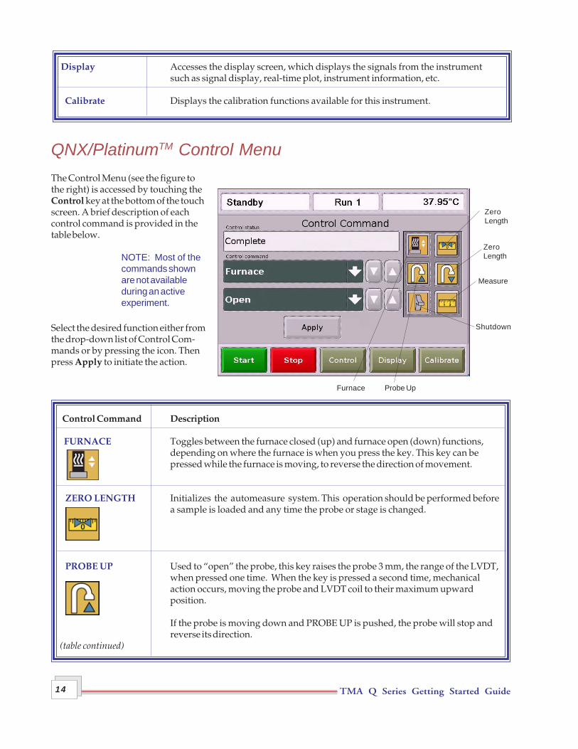
QNX/PlatinumTM Control MenuThe Control Menu (see the figure tothe right) is accessed by touching theControl key at the bottom of the touchscreen. A brief description of eachcontrol command is provided in thetable below.
NOTE: Most of thecommands shownare not availableduring an activeexperiment.
Select the desired function either fromthe drop-down list of Control Com-mands or by pressing the icon. Thenpress Apply to initiate the action.
Control Command Description
FURNACE Toggles between the furnace closed (up) and furnace open (down) functions,depending on where the furnace is when you press the key. This key can bepressed while the furnace is moving, to reverse the direction of movement.
ZERO LENGTH Initializes the automeasure system. This operation should be performed beforea sample is loaded and any time the probe or stage is changed.
PROBE UP Used to “open” the probe, this key raises the probe 3 mm, the range of the LVDT,when pressed one time. When the key is pressed a second time, mechanicalaction occurs, moving the probe and LVDT coil to their maximum upwardposition.
If the probe is moving down and PROBE UP is pushed, the probe will stop andreverse its direction.
(table continued)
ZeroLength
ZeroLength
Measure
Shutdown
Furnace Probe Up

TMA Q Series Getting Started Guide 15
Control Command Description
PROBE DOWN Used to “close” the probe, this key lowers the probe 3 mm, the range of the LVDT,when pressed one time. When the key is pressed a second time, mechanicalaction occurs, centering the LVDT coil.
If the probe is moving up and PROBE DOWN is pushed, the probe will stop andreverse its direction.
SHUTDOWN Shuts down and resets the instrument.
MEASURE Measures your sample’s length automatically; use this key before beginningthe run. The measured length is transferred to the instrument control softwareand the value is recorded in the Sample Size field.
NOTE: MEASURE is not used with the flexural probe.
AIR COOL Toggles the air cool function on or off. This is the same function as Air Cool onthe instrument control software.
RESET SAVED PARAMETERS Resets the saved instrument parameters and resets the instrument.

TMA Q Series Getting Started Guide16
QNX/PlatinumTM DisplayTouch Screen OptionsThe Display Options are accessed by touchingthe Display key at the bottom of the touchscreen. The keys shown in the figure to the rightare displayed.
A brief description of the function of each key isprovided in the table below.
Key Name Description
SEGMENTS Accesses the experimental method that is currently being used for this experi-ment.
INFORMATION Displays instrument information such as the software version, options, andthe IP address.
STATUS Displays the three main signals indicating the current status of the experiment.
SIGNALS Displays the real-time signal data that comes directly from the instrument. Thesignals displayed here are customized through the instrument control soft-ware by accessing Tools/Instrument Preferences.
PLOT Displays a time-based plot of data as it is received from the instrument duringexperiments.
SCREEN SAVER Allows you to choose a screen saver for the touch screen.
HOME Returns to the opening window.
TMA Q Series Getting Started Guide 17
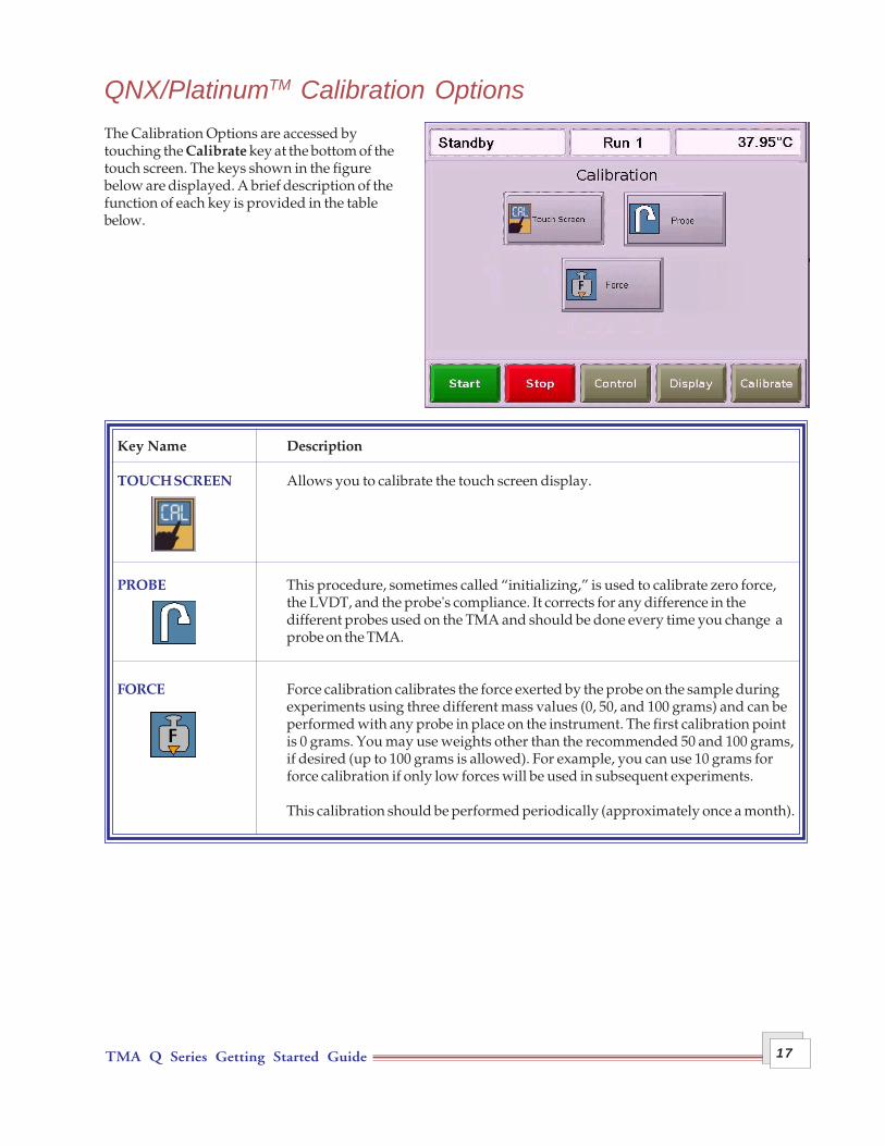
QNX/PlatinumTM Calibration OptionsThe Calibration Options are accessed bytouching the Calibrate key at the bottom of thetouch screen. The keys shown in the figurebelow are displayed. A brief description of thefunction of each key is provided in the tablebelow.
Key Name Description
TOUCH SCREEN Allows you to calibrate the touch screen display.
PROBE This procedure, sometimes called “initializing,” is used to calibrate zero force,the LVDT, and the probe's compliance. It corrects for any difference in thedifferent probes used on the TMA and should be done every time you change aprobe on the TMA.
FORCE Force calibration calibrates the force exerted by the probe on the sample duringexperiments using three different mass values (0, 50, and 100 grams) and can beperformed with any probe in place on the instrument. The first calibration pointis 0 grams. You may use weights other than the recommended 50 and 100 grams,if desired (up to 100 grams is allowed). For example, you can use 10 grams forforce calibration if only low forces will be used in subsequent experiments.
This calibration should be performed periodically (approximately once a month).

TMA Q Series Getting Started Guide18
The TMA Touch Screen (Original)The TMA Q400 instruments have a built-in integrateddisplay and keypad in the form of a touch screen for localoperator control. The functions shown on the screenchange depending upon the menu you are using. Thissection briefly describes the functions of the keys shownon the touch screen displays.
The status line along the top of the display (see the figureto the right) shows the current instrument status, currentrun number, and temperature.
At the bottom of the screen is a set of five keys that areused for the primary instrument functions. These keysare available to you regardless of the menu selected. Seethe next section for an explanation of the primary functionkeys.
NOTE: Experiment information andinstrument constants are entered fromthe controller keyboard, not the instrument touch screen.
Primary Function KeysThis set of keys, found at the bottom of the touch screen, are used to perform the basic functions of the instru-ment and to access the two main screens. See the table below for details.
Key Name Description
Begins the experiment. This is the same function as Start on the instrumentcontrol software.
If an experiment is running, this key ends the method normally, as though it hadrun to completion; i.e., the method-end conditions go into effect and the data thathas been generated is saved. This is the same function as Stop on the instrumentcontrol software.
If an experiment is not running (the instrument is in a standby or method-endstate), the Stop key will halt any activity (air cool, all mechanical motion, etc.).
If an experiment is running, REJECT ends the method. The the method-endconditions go into effect just as if the method had run to completion. However,the data that has been generated is discarded. This is the same function as Rejecton the instrument control software.
Displays the Control Menu touch screen keys. These are used to control certaininstrument actions.
Accesses the Display Menu screen, which is used to select the desired displayoption.
Primary Function Keys
Status Line
TMA Q Series Getting Started Guide 19
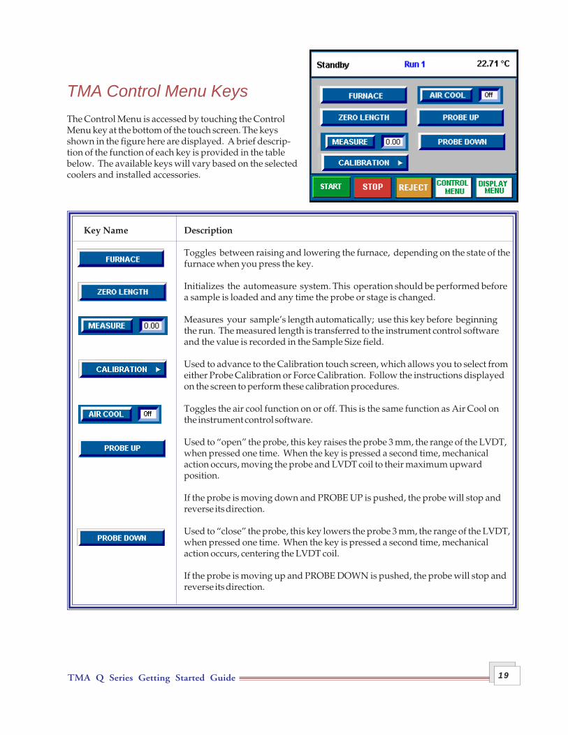
TMA Control Menu KeysThe Control Menu is accessed by touching the ControlMenu key at the bottom of the touch screen. The keysshown in the figure here are displayed. A brief descrip-tion of the function of each key is provided in the tablebelow. The available keys will vary based on the selectedcoolers and installed accessories.
Key Name Description
Toggles between raising and lowering the furnace, depending on the state of thefurnace when you press the key.
Initializes the automeasure system. This operation should be performed beforea sample is loaded and any time the probe or stage is changed.
Measures your sample’s length automatically; use this key before beginningthe run. The measured length is transferred to the instrument control softwareand the value is recorded in the Sample Size field.
Used to advance to the Calibration touch screen, which allows you to select fromeither Probe Calibration or Force Calibration. Follow the instructions displayedon the screen to perform these calibration procedures.
Toggles the air cool function on or off. This is the same function as Air Cool onthe instrument control software.
Used to “open” the probe, this key raises the probe 3 mm, the range of the LVDT,when pressed one time. When the key is pressed a second time, mechanicalaction occurs, moving the probe and LVDT coil to their maximum upwardposition.
If the probe is moving down and PROBE UP is pushed, the probe will stop andreverse its direction.
Used to “close” the probe, this key lowers the probe 3 mm, the range of the LVDT,when pressed one time. When the key is pressed a second time, mechanicalaction occurs, centering the LVDT coil.
If the probe is moving up and PROBE DOWN is pushed, the probe will stop andreverse its direction.

TMA Q Series Getting Started Guide20
Display Menu KeysThe Display Menu is accessed by touching the DISPLAYMENU key at the bottom of the touch screen. The menushown in the figure here will be displayed. A briefdescription of the function of each key is provided in thetable below.
Key Name Description
Accesses the experimental procedure that is currently being used and highlightsthe active segment.
Displays the three main signals indicating the current status of the experiment.
Displays instrument information such as the software version, options, and theIP (Internet Protocol) address.
Displays the real-time signal data that comes directly from the instrument. Thesignals displayed here are customized through the instrument control software.
Ensures proper shutdown of the instrument before turning off the power.
Beeps the controller that is connected to the instrument.
Returns to the opening window.

TMA Q Series Getting Started Guide 21
Options and AccessoriesSeveral optional probes and a cooling accessory are available from TA Instruments to be used with the TMA. Abrief description of each one follows. For more information refer to the online documentation.
Probes• Film/Fiber Probe: The TMA film/fiber accessory can be used to measure the physical properties of fibers or
films as a function of force, temperature, or time.
• Flexure Accessory: The Flexure Accessory can be used on the TMA for three-point bending studies tomeasure the flexibility and strength of a variety of materials, such as composites, plastics, and PC boards.It employs a knife-edged probe and either of two types of fixtures, quartz or low-friction aluminum,depending upon the type of experiment desired.
• Dilatometer Accessory: The dilatometer accessory kit can be used to determine the volume coefficient ofexpansion.
• Parallel Plate Rheometer Accessory: The parallel plate rheometer accessory can be used to obtainviscosity-temperature or viscosity-time data on substances at low shear rates, over the range of 10 to 107
Pa-sec (1 to 106 Poise).
• Hemispherical Probe: The hemispherical probe is used with the standard quartz stage to obtain softeningpoint data on substances. It is installed, operated, and calibrated using the same procedures as for thestandard expansion and penetration probes.
Mechanical Cooling AccessoryThe Mechanical Cooling Accessory (MCA) is designed to provideyou with a source of continuous cooling for the TMA, while elimi-nating the need for liquid nitrogen or dry ice. It is a portable,freestanding refrigeration system that can be placed on the floorunder a lab bench to conserve counter space. The MCA has a two-stage compressor system that operates in a cascade fashion (first onecompressor turns on, then the other compressor joins in). Refriger-ant is carried from the unit through an insulated coaxial hose to thecooling head.
When using the MCA it is important to select Tools/InstrumentPreferences/TMA Page and check the box "MCA attached" to avoiddamage to the system.

TMA Q Series Getting Started Guide22
Instrument SpecificationsThe tables found on the following pages contain the technical specifications for the TMA.
TMA Instrument Characteristics
Dimensions Depth 55.9 cm (22 in.)Width 45.5 cm (18 in.)
Furnace Open Height 64.8 cm (25.5 in.) Furnace Closed Height 61 cm (24 in.)
Weight (approx.) 31.4 kg (69 lb)Weight with Transformer 39.5 kg (87 lbs)
Power 120 Vac, 47–63 Hz, 1.44 kVA standard230 Vac, 47–63 Hz, 1.44 kVA if configured with a step-downtransformer
Accessory Outlets Power: 120 V, 47–63 Hz, 400 VA each (used with TA accessoriesonly)
Operating Environment Temperature: 15–30 °C Conditions Relative Humidity: 5–80 % (non-condensing)
Installation Category IIPollution Degree 2Maximum Altitude: 2000 m
Temperature Range –150 to 1000oC
Sample Height 25 mm (1 inch) maximum Sample Thickness for Film/Fiber 0.5 mm maximum
Sample Diameter 10 mm (0.39 in) maximum
Sensitivity 15 nanometers
Displacement Range +2.5 mm (+0.10 inch)
Linearity +0.5 %
Loading 0.001 to 1.0 Newtons (102 g)
Purge gases Calibrated for: air, argon, helium, nitrogen, or oxygen
Typical purge flow rate 100 ml/min (-100 °C and above) or 200 ml/min (-150 °C andabove).
Programmed Heating Rate 0.01 to 200 oC/min
Temperature Reproducibility +2 oC

TMA Q Series Getting Started Guide 23
Unpacking/Repacking the TMAThe instructions needed to unpack and repack the instrument are found as separate unpacking instructions inthe shipping box and in the online documentation associated with the instrument control software. You maywish to retain all of the shipping hardware, the plywood, and boxes from the instrument in the event you wishto repack and ship your instrument.
WARNING: Have an assistant help you unpack this unit. Do not attempt to do thisalone.
Installing the InstrumentBefore shipment, the TMA instrument is inspected both electrically and mechanically so that it is ready foroperation upon proper installation. Only limited instructions are given in this manual, consult the onlinedocumentation for additional information. Installation involves the following procedures:
• Inspecting the system for shipping damage and missing parts• Installing a voltage configuration unit.• Connecting the TMA to the TA Instruments controller• Connecting cables and gas lines.
It is recommended that you have your TMA installed by a TA Instruments Service Representative, call for aninstallation appointment when you receive your instrument.
CAUTION: To avoid mistakes, read this entire chapter before you begin installation.
NOTE: If you plan to ship your TMA by commercial carrier, you will need to remove the voltageconfiguration unit first. Please refer to the online help accessed through the Help menu fordetailed instructions on transporting the TMA.
Inspecting the SystemWhen you receive your TMA, look over the instrument and shipping container carefully for signs of shippingdamage, and check the parts received against the enclosed shipping list.
• If the instrument is damaged, notify the carrier and TA Instruments immediately.• If the instrument is intact but parts are missing, contact TA Instruments.
Chapter 2Installing the TMA

TMA Q Series Getting Started Guide24
Choosing a LocationBecause of the sensitivity of TMA experiments, it is important to choose a location for the instrument using thefollowing guidelines. The TMA should be:
In ... a temperature-controlled area.... a clean, vibration-free environment.... an area with ample working and ventilation space.
On ... a stable work surface.
NOTE: Placing the TMA on a stable, vibration-free work surface is very important to instrumentperformance.
Near ... a power outlet (120 Vac, 50 or 60 Hz, 15 amps, or 230 Vac, 50 or 60 Hz, 10 amps if configured witha step down transformer).
...your TA Instruments thermal analysis controller. ...sources of compressed lab air and purge gas supplies with suitable regulators.
CAUTION: Your air source must be clean, dry, and oil-free to ensure proper operationof the TMA.
Awayfrom ... any flammable materials.
... dusty environments.
... exposure to direct sunlight.
... direct air drafts (fans, room air ducts).
... poorly ventilated areas.
... noisy or mechanical vibrations.
CAUTION: Drying out the instrument may be needed, if it has been exposed to humidconditions. Certain ceramic materials used in this equipment may absorb moisture,causing leakage currents to exceed those specified in the applicable standards untilmoisture is eliminated. It is important to be certain that the instrument ground isadequately connected to the facilities ground for safe operation.
Run the following method to dry out the TMA:1 Ramp at 10°C/min to 400°C2 Isothermal for 30 min.
TMA Q Series Getting Started Guide 25
Fuse
Fuse Holder
Fuse
Voltage Configuration Unit
PowerEntryModule
Captive Fasteners
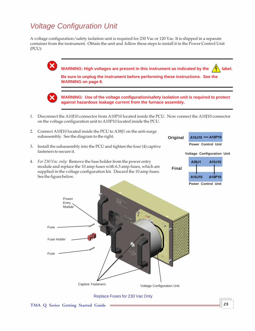
Replace Fuses for 230 Vac Only
Voltage Configuration UnitA voltage configuration/safety isolation unit is required for 230 Vac or 120 Vac. It is shipped in a separatecontainer from the instrument. Obtain the unit and follow these steps to install it in the Power Control Unit(PCU):
WARNING: High voltages are present in this instrument as indicated by the label.
Be sure to unplug the instrument before performing these instructions. See theWARNING on page 8.
WARNING: Use of the voltage configuration/safety isolation unit is required to protectagainst hazardous leakage current from the furnace assembly.
1. Disconnect the A10J10 connector from A10P10 located inside the PCU. Now connect the A10J10 connectoron the voltage configuration unit to A10P10 located inside the PCU.
2. Connect A10J10 located inside the PCU to A38J1 on the anti-surgesubassembly. See the diagram to the right.
3. Install the subassembly into the PCU and tighten the four (4) captivefasteners to secure it.
4. For 230 Vac only: Remove the fuse holder from the power entrymodule and replace the 10 amp fuses with 6.3 amp fuses, which aresupplied in the voltage configuration kit. Discard the 10 amp fuses.See the figure below.
Original
Power Control Unit
Voltage Configuration Unit
Power Control Unit
Final

TMA Q Series Getting Started Guide26
Connecting Cables and LinesTo connect the cables and gas lines, you will need access to the TMA instrument’s rear panel. All directionaldescriptions are written on the assumption that you are facing the back of the instrument.
NOTE: Connect all cables before connecting the power cords to outlets. Tighten the thumb-screws on all computer cables.
CAUTION: Whenever plugging or unplugging power cords, handle them by the plugs,not by the cords.
WARNING: Protect power and communications cable paths. Do not create trippinghazards by laying the cables across accessways.
WARNING: DO NOT position the instrument so that it isdifficult to turn off the power switch or to unplug the power cord.
Ports
The TMA has nine ports that are located on the back of the instrument. The following table provides a descrip-tion of function of each port. Refer to this list when connecting cables and lines.
Port Function
Ethernet Provides communication capabilities.
Com 1 Diagnostic port (factory use only).
Com 2 Accessory port.
Event Capable of the following functions: general purpose relay contact closure, orgeneral purpose input 4 – 24 Vdc for external syncing. This port is not used forstandard operation.
24 VDC output This port is not used with the TMA.(table continued)
Five Ports on Left Rear of TMA
Ethernet COM 1 COM 2 Event 24 VDC Output
TMA Q Series Getting Started Guide 27
Port Function
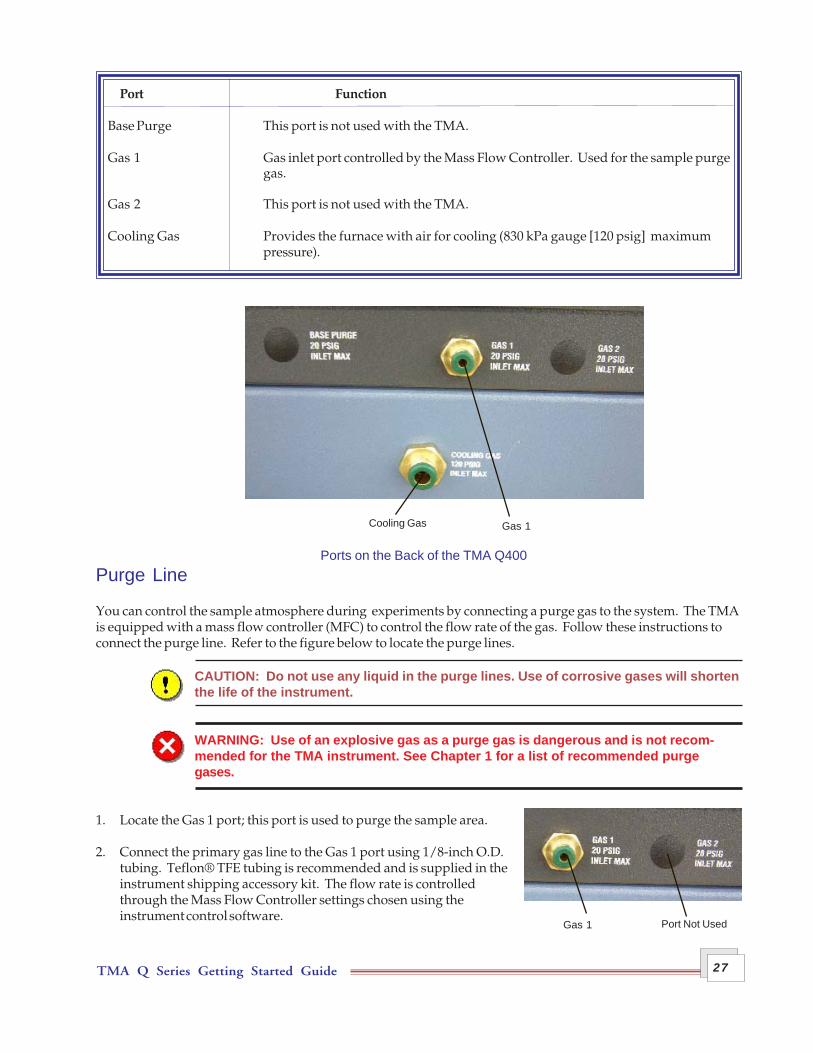
Base Purge This port is not used with the TMA.
Gas 1 Gas inlet port controlled by the Mass Flow Controller. Used for the sample purgegas.
Gas 2 This port is not used with the TMA.
Cooling Gas Provides the furnace with air for cooling (830 kPa gauge [120 psig] maximumpressure).
Purge Line
You can control the sample atmosphere during experiments by connecting a purge gas to the system. The TMAis equipped with a mass flow controller (MFC) to control the flow rate of the gas. Follow these instructions toconnect the purge line. Refer to the figure below to locate the purge lines.
CAUTION: Do not use any liquid in the purge lines. Use of corrosive gases will shortenthe life of the instrument.
WARNING: Use of an explosive gas as a purge gas is dangerous and is not recom-mended for the TMA instrument. See Chapter 1 for a list of recommended purgegases.
1. Locate the Gas 1 port; this port is used to purge the sample area.
2. Connect the primary gas line to the Gas 1 port using 1/8-inch O.D.tubing. Teflon® TFE tubing is recommended and is supplied in theinstrument shipping accessory kit. The flow rate is controlledthrough the Mass Flow Controller settings chosen using theinstrument control software.
Ports on the Back of the TMA Q400
Gas 1Cooling Gas
Gas 1 Port Not Used

TMA Q Series Getting Started Guide28
The purge gas flows through the instrument and is channeledinternally to the sample purge line shown in the figure to the left.
3. Make sure that the pressure of your purge gas source isregulated between 100 and 140 kPa gauge (15 and 20 psig).
Connecting the Cooling Gas Line
Air cooling is used to cool the TMA furnace to room temperature.
Follow the procedure below to install thecooling gas line for air cool:
1. Locate the Cooling Gas fitting, a 1/4-inchLegris fitting on the right side of the TMAcabinet back, marked with an 830 kPagauge (120 psig) maximum warning label(see the figure to the right).
2. Make sure your compressed air source isdry, filtered, and regulated to between 170and 830 kPa gauge (25 and 120 psig).
3. Connect the compressed air line to theCooling Gas fitting.
Air CoolLine
SamplePurgeLine
Cooling Gas Fitting

TMA Q Series Getting Started Guide 29
Installing the StageTo install the stage on the TMA, check to make sure thefurnace is raised and off to the side. Then follow these steps(refer to the figure here for illustration of the parts):
1. Remove the stage shield by lifting it straight up. (This is afriction fit.)
2. Turn the large stage nut counterclockwise to remove it.
3. Twist the stage retainer ring (with key slots) counter-clockwise, and pull it up off the three posts.
4. Remove the stage from the accessory kit.
5. Slide the wave washer (washer with rippled edges)down over the top of the stage so that it fits on the flange.
6. Slide the stage retainer ring down over the top of thestage so that it rests on top of the wave washer.
7. Insert the whole assembly (stage, wave washer, andretainer ring) into the stage opening, aligning the keyslots in the retainer ring with the posts.
8. Press down and turn the retainer ring clockwise to lockthe assembly in position.
9. Replace the large stage nut, turning it clockwise to install it.
10. Attach the thermocouple to the stage as follows:
a. Position the tip of the thermocouple so that it bends at a 90° angle and lies flat against the platform. Itshould be close to, but not touching the sample.
b. Hold the thermocouple against the stage assembly,and put on the spring clip to keep the thermocouple inplace (see the figure below).
11. Place the stage shield onthe stage, aligning the slotin the bottom over thethermocouple (see the figureto the right).
12. Install one of the probesas directed in the nextsection. (Refer to Chapter 3for guidelines to use whenselecting a probe.)
13. Rotate the furnace intoposition over the stage.
StageShield
StageNut
StageRetainerRing
WaveWasher
Stage
StageOpening
Keyways
Flange
Posts
Stage Shield
Thermocouple
Probe
Stage
Springclip

TMA Q Series Getting Started Guide30
Installing the Expansion/Penetration ProbesWhen you first receive the TMA, you will need to install a probe. Later, if a different sample form is used, youcan change to the appropriate probe for the experiment. (Refer to Chapter 3 for details on probe selection.) Theprocedures that follow explain the installation and removal of the expansion, macro expansion, penetration,flexure, dilatometer, and hemispherical probes.
Installing a Probe
1. Raise the furnace and rotate it clockwise to move it off to the side.
2. Insert the core end of the probe carefully into the opening in the TMA stage.
3. Loosen the probe-locking lever, which is the knurled post found behind the weight tray door, by turning itcounterclockwise. Hold the probe-locking lever in the up position and continue lowering the probe into thestage until you can feel it seat in the locking mechanism.
4. Tighten the probe-locking lever by turning it clockwise.
5. Calibrate the newly installed probe as directed in the online help found in the instrument control software.
Removing a Probe
1. Raise the furnace, and rotate it clockwise to move it off to the side.
2. Grasp the top of the probe with one hand. Using the other hand, locate and hold the probe-locking lever,found behind the door that covers the weight tray.
3. Unscrew the locking lever by turning it counterclockwise approximately one turn.
4. Raise the probe gently and twist slightly to aid its removal from the stage opening.

TMA Q Series Getting Started Guide 31
Ethernet Switch Setup
In order to connect the instrument to a network, you will need to make the necessary cable connections asdescribed below. The instrument and controller will be connected to an Ethernet switch. In addition, there areinstructions for connecting the controller to a LAN.
Connecting the Instrument to the Switch
1. Locate the Ethernet port on the left rear of the instrument (shown inthe figure to the right).
2. Connect one end of the Ethernet cable into the instrument's Ethernetport.
3. Connect the other end of the Ethernet cable to one of the network portson the Ethernet switch (shown in the figure below).
4. Check the configuration switches, located on the back panel. They mustbe set to off, or the up position, for the controller to communicate to theinstruments.
5. Check the Ethernet port on the rear of the instrument. If communica-tion between the instrument and the switch has been properly estab-lished, a solid green light and flashing yellow light will appear at the port.
6. Follow the directions in the next section to connect the controller to the Ethernet switch.
Connecting the Controller to the Switch
1. Locate the Ethernet port on the back of the computer.
2. Plug one end of the Ethernet cable into the computer's Ethernet port (shown in thefigure to the right).
3. Connect the other end of the cable to one of the network ports on the switch.
4. Check the Ethernet port on the rear of the computer. If communication between thecomputer and the switch has been properly established, a solid green light andflashing yellow light will appear at the port.
5. Follow the directions in the next section to connect the controller to a LAN for net-working capabilities.
Ethernet Connection
Yellow Light Green Light
Configuration Switches
Ethernet Switch
ComputerEthernet Port
TMA Q Series Getting Started Guide32
Ethernet Connection
Yellow Light Green Light
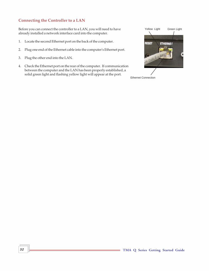
Connecting the Controller to a LAN
Before you can connect the controller to a LAN, you will need to havealready installed a network interface card into the computer.
1. Locate the second Ethernet port on the back of the computer.
2. Plug one end of the Ethernet cable into the computer's Ethernet port.
3. Plug the other end into the LAN.
4. Check the Ethernet port on the rear of the computer. If communicationbetween the computer and the LAN has been properly established, asolid green light and flashing yellow light will appear at the port.

TMA Q Series Getting Started Guide 33
Power Entry Module
Reset Button
Power SwitchThe power switch is located at the rear of the instrument. It is part of theassembly called the power entry module, which also contains the powercable connection and fuses. The power switch is used to turn theinstrument on and off.
Power CableNOTE: A <HAR>-marked (harmonized) power cablemeeting the standards of the country of installation isrequired for the European Economic Area.
Install the power cable as follows:
1. Make sure the TMA POWER switch is in the Off (0) position.
2. Plug the power cable into the TMA power entry module.
CAUTION: Before plugging the TMA power cable into the wall outlet, make sure theinstrument is compatible with the line voltage. Check the label on the voltage con-figuration unit panel to verify the voltage.
3. Plug the power cable into the wall outlet.

TMA Q Series Getting Started Guide34
Starting the TMA1. Check all connections between the TMA and the controller. Make sure each component is plugged into the
correct connector.
2. Set the instrument power switch to the ON (1) position.
After the proper power up sequence, the TA Instruments logo will be displayed on the touch screen, this indi-cates that the instrument is ready for use.
NOTE: Allow the TMA to warm up for at least 30 minutes before performing an experiment.
Shutting Down the TMABefore you decide to power down your instrument, consider the following:
• All of the components of your thermal analysis system are designed to be powered on for long periods.
• The electronics of the TMA and the controller perform more reliably if power fluctuations caused byturning units on and off are minimized.
For these reasons, turning the system and its components on and off frequently is discouraged. Therefore, whenyou finish running an experiment on your instrument and wish to use the thermal analysis system for someother task, it is recommended that you leave the instrument on.
To ensure proper shutdown of the instrument, it is recommended that you initiate the "Shutdown Instrument"function before turning off or resetting your instrument. This function is available on the instrument touchscreen or through the Instrument Control software.
To power down your instrument set the power switch to the OFF (0) position.

TMA Q Series Getting Started Guide 35
Using the TMAAll of your TMA experiments will have the following general outline. In some cases, not all of these stepswill be performed. The majority of these steps are performed using the instrument control software. Theinstructions needed to perform these actions can be found in the online help in the instrument control pro-gram; therefore, they will not all be covered in detail here.
• Calibrating the instrument• Selecting, calibrating, and zeroing the probe• Selecting the desired mode (standard or calibration) through the TA instrument control software• Preparing and loading the sample• Adjusting the thermocouple position and closing the furnace• Creating or choosing the test procedure and entering sample and instrument information through the
TA instrument control software• Setting the purge gas flow rate• Adding coolant to the furnace reservoir for subambient operation, if applicable• Starting the experiment.
To obtain accurate results, follow procedures carefully.
Before You BeginBefore you set up an experiment, ensure that the TMA and the controller have been installed properly. Makesure you have:
• Made all necessary cable connections from the TMA to the computer• Connected all gas lines• Powered up the unit• Connected any desired accessories• Connected the instrument with the controller• Become familiar with controller operations• Calibrated the TMA, if necessary.
Chapter 3Use, Maintenance, & Diagnostics

TMA Q Series Getting Started Guide36
Calibrating the TMATo obtain accurate experimental results, calibrate the TMA when you first install it. To keep your TMAworking to the highest level of performance possible, you should calibrate periodically thereafter. A briefdescription of each calibration is outlined below. For details on how to perform that calibration, refer to theonline help documentation accessed through the instrument control software.
Force CalibrationForce calibration calibrates the force exerted by the probe on the sample during experiments using threedifferent mass values (0, 50, and 100 grams) and can be performed with any probe in place on the instrument.The first calibration point is 0 grams. You may use weights other than the recommended 50 and 100 grams, ifdesired (up to 100 grams is allowed). For example, you can use 10 grams for force calibration if only lowforces will be used in subsequent experiments.
This calibration should be performed periodically (approximately once a month) and can be performed fromthe TA instrument control program or the instrument's touch screen.
NOTE: A force calibration performs the functions of a probe calibration (see the next sec-tion). Therefore, it is not necessary to perform a probe calibration immediately following aforce calibration.
Probe CalibrationThis procedure, sometimes called “initializing,” is used to calibrate zero force, the LVDT, and the probe'scompliance. It corrects for any difference in the different probes used on the TMA and should be done everytime you change a probe on the TMA. This calibration can be performed from the TA instrument controlprogram or the instrument's touch screen.
Temperature CalibrationTemperature calibration is based on a run, conducted in the calibration mode, in which a temperature stan-dard (e.g., indium) is heated through its melting point. The recorded melting point of this standard is com-pared to the known melting point, and the difference is calculated for temperature calibration.
In addition, you can use up to four other standards to calibrate temperature. If you use one pair of knownand observed points, the entire curve is offset, or shifted, to the actual melting point. If you use multiplestandards, the temperature is corrected by a cubic spline fit between the points with fixed offset valuesbeyond the calibration window. This can create a small discontinuity in the heating rate. The multiple-pointtemperature calibration is more accurate than the one-point calibration.
For all probe types except the film/fiber accessory, small flattened pieces of standard metals are placed onthe stage. To protect the stage from amalgamation with the metal, it is recommended that aluminum orplatinum be placed between the stage and the metal standard. The end of the probe can also be wrapped withfoil for added protection.
For the film/fiber probe, metal wires can be crimped into the aluminum balls and used for calibration.

TMA Q Series Getting Started Guide 37
When to Calibrate:
The sample thermocouple should be calibrated in the following situations:
• When the TMA is first installed• When the sample thermocouple is changed• When the TMA is serviced or repaired• Periodically (approximately once a month)• If you are changing the temperature range of interest• If the run data obtained seems to be inaccurate• When the purge gas is changed.
Cell ConstantCell constant calibration is based on a run conducted in the calibration mode in which a known standard (e.g.,aluminum or copper) is heated through its transition temperature and data is gathered for analysis. The cellconstant is calculated by dividing the actual coefficient of expansion of the standard by the measured coeffi-cient of expansion. The cell constant is then entered in the instrument control software for calibration of theinstrument.
Using the default cell constant value of 1.000 is usually adequate; however, for greatest accuracy, calibrationshould be performed.
It is recommended that you follow the procedures of ASTM Standard Test Method E831 to perform the cellconstant calibration.

TMA Q Series Getting Started Guide38
Running a TMA ExperimentCAUTION: Drying out the instrument may be needed, if it has been exposed to humidconditions. Certain ceramic materials used in this equipment may absorb moisture,causing leakage currents to exceed those specified in the applicable standards untilmoisture is eliminated. It is important to be certain that the instrument ground isadequately connected to the facilities ground for safe operation.
Run the following method to dry out the TMA:
1 Ramp at 10°C/min to 400°C2 Isothermal for 30 min.
All of your TMA experiments will follow the same general outline (see page 35). In some cases, not all of thesesteps will be performed. The following sections provide more information on these steps. See the instrumentcontrol software online help for anything not covered in this manual.
Selecting a ProbeThe type of probe that you use is dependent upon the kind of testing information desired. The table belowlists the probes available, their specifications, and the type of testing yielded.
When choosing a probe to use for an experiment, follow these steps:
1. Select and install the appropriate probe for the analysis desired. See the table on the next page for a briefdescription of the various probes available.
2. Perform a Probe Calibration for a newly installed probe or “zero” an already installed probe. (Thezeroing instructions are found in the next section.)
TMA Probe Types
Probe Type ContactDiameter Pressure Exerted by Types of Tests Yieldedmm (in.) 0.01 N Load
Penetration 0.89 (0.035) 16 kPa Softening pointMelting point
Expansion 2.54 (0.100) 1.9 kPa Expansion coefficientCompression modulusTensile modulusGlass transition
Macro Expansion 6.07 (0.239) 0.34 kPa Expansion coefficientCompression modulusTensile modulusGlass transition
Film/Fiber Not applicable Not applicable Tensile stress(table continued)

TMA Q Series Getting Started Guide 39
Probe Type ContactDiameter Pressure Exerted by Types of Tests Yieldedmm (in.) 0.01 N Load
Flexure 5.08 (0.2) 0.49 kPa Deflection temperatureFlexibility
Dilatometer 6.07 (0.239) 0.34 kPa Expansion coefficient
Parallel Plate 9.52 (0.375) 0.14 kPa Viscosity-temperatureViscosity-timeWall shear rate
Hemispherical ~2.54 (0.1) ~1.9 kPa Softening point
NOTE: Refer to online help for details regarding the probes.
Zeroing the Auto Measure SystemThis procedure is used to initialize the auto-length measure system. It should be performed before eachexperiment to ensure accurate sample length measurements. To zero the TMA auto measure system, simplypress the ZERO LENGTH key on the touch screen.

TMA Q Series Getting Started Guide40
Guidelines for Handling SamplesSample Preparation
Sample preparation will vary based on the selected probe type. Guidelines for samples used for penetrationand expansion studies are detailed below:
• They should be as flat as possible, with parallel ends, to ensure stable placement on the stage.
• Samples should be long enough (5 to 10 mm for most materials) for adequate resolution, keeping inmind that large samples may experience temperature gradients during high heating rates.
• Thermoplastic samples can be heated and formed into suitable specimens and then cooled; however,this process may change important thermal history.
• If you plan to run samples that may melt and adhere to the stage, it is best to use the quartz protectivewafers under the sample. See the next section for information.
Sample Loading
After your sample has been prepared, follow these steps to load it on the TMA:
1. Raise the furnace and rotate it clockwise to move it off to the side.
2. Remove any previously run samples from the stage and ensure that no residue remains.
NOTE: It is recommended that you place a quartz wafer or a piece of thin aluminum foilbetween the stage and any thermoplastic samples to prevent damage to the stage. See step3.
3. For samples that may melt and adhere to the stage: Place the protective quartz wafer onto the stage andcenter it.
4. Access the Control Menu on the touch screen. Press ZEROLENGTH on the touch screen to provide a zero reference point.
5. Open (raise) the probe. (Press PROBE UP on the touch screen).
6. Place the sample on the stage under the probe tip (see the figureto the right).
7. Adjust the sample thermocouple, if needed. Regardless of thesize or shape of the sample that you are running on the TMA,position the tip of the thermocouple so that it bends at a gentle90° angle and lies flat against the platform. It should be close to,but not touching the sample (as shown here). Note that a sharpbend could damage the thermocouple.
8. Measure the sample length as follows: Before you begin theexperiment, it is important to take an initial measurement of thesample. To do this, simply press the MEASURE key on theinstrument touch screen. This automatically applies the preloadforce that you have specified through the instrument controlprogram, then measures and stores the sample length.

TMA Q Series Getting Started Guide 41
Starting an ExperimentBefore you start the experiment, ensure that the TMA is connected with the controller, the sample is loaded,the furnace is closed, and you have entered all necessary information through the instrument control soft-ware.
NOTE: Once the experiment is started, operations are best performed at the computerkeyboard. The TMA is very sensitive to motion and might pick up the vibration caused bytouching a key on the instrument touch screen.
Stopping an ExperimentIf for some reason you need to discontinue the experiment, you can stop it at any point by selecting Stopthrough the instrument control software or by pressing the STOP key on the touch screen.
Another function that stops the experiment is REJECT. However, the Reject function discards all of the datafrom the experiment while the Stop function saves any data collected up to the point at which the experimentwas stopped.

TMA Q Series Getting Started Guide42
Maintaining the InstrumentThe primary maintenance procedures described in this section are the customer’s responsibility. Any furthermaintenance should be performed by a representative of TA Instruments or other qualified service personnel.Consult the online documentation installed with the instrument control software for further information.
WARNING: Because of the high voltages in this instrument, untrained personnel mustnot attempt to test or repair any electrical circuits.
CAUTION: Before using any cleaning or decontamination method except thoserecommended by TA Instruments in this chapter, please check with TA Instruments tomake sure that the proposed method will not damage the equipment.
Cleaning the Touch ScreenYou can clean the TMA touch screen as often as you like. The touch screen should be cleaned with a house-hold liquid glass cleaner and soft cloth. Wet the cloth, not the touch screen with the glass cleaner, and thenwipe off the touch screen and surrounding surfaces.
WARNING: Do not use harsh chemicals, abrasive cleansers, steel wool, or any roughmaterials to clean the touch screen as you may scratch the surface and degrade itsproperties.
Cleaning the Probe AssemblyAfter each experiment, check the probe assembly. If the probe is dirty, remove it using the procedures foundin Chapter 2 and the online help, then clean the probe as follows:
1. Use contact cleaner or acetone applied with a soft brush or cloth to clean the LVDT core and the upperprobe.
2. Heat the end of the quartz probe with a Bunsen burner until the residue evaporates and the probe isclean. Heat the probe very slowly if the sample contains a large amount of glass or mineral filler.
NOTE: Probes may also be cleaned in a nitric acid solution.
TMA Q Series Getting Started Guide 43
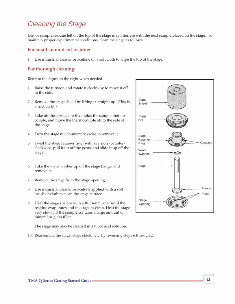
Cleaning the StageDirt or sample residue left on the top of the stage may interfere with the next sample placed on the stage. Tomaintain proper experimental conditions, clean the stage as follows:
For small amounts of residue:
1. Use industrial cleaner or acetone on a soft cloth to wipe the top of the stage.
For thorough cleaning:
Refer to the figure to the right when needed.
1. Raise the furnace, and rotate it clockwise to move it offto the side.
2. Remove the stage shield by lifting it straight up. (This isa friction fit.)
3. Take off the spring clip that holds the sample thermo-couple, and move the thermocouple off to the side ofthe stage.
4. Turn the stage nut counterclockwise to remove it.
5. Twist the stage retainer ring (with key slots) counter-clockwise, pull it up off the posts, and slide it up off thestage.
6. Take the wave washer up off the stage flange, andremove it.
7. Remove the stage from the stage opening.
8. Use industrial cleaner or acetone applied with a softbrush or cloth to clean the stage surface.
9. Heat the stage surface with a Bunsen burner until theresidue evaporates and the stage is clean. Heat the stagevery slowly if the sample contains a large amount ofmineral or glass filler.
The stage may also be cleaned in a nitric acid solution.
10. Reassemble the stage, stage shield, etc. by reversing steps 6 through 2.
StageShield
StageNut
StageRetainerRing
WaveWasher
Stage
StageOpening
Keyways
Flange
Posts
TMA Q Series Getting Started Guide44
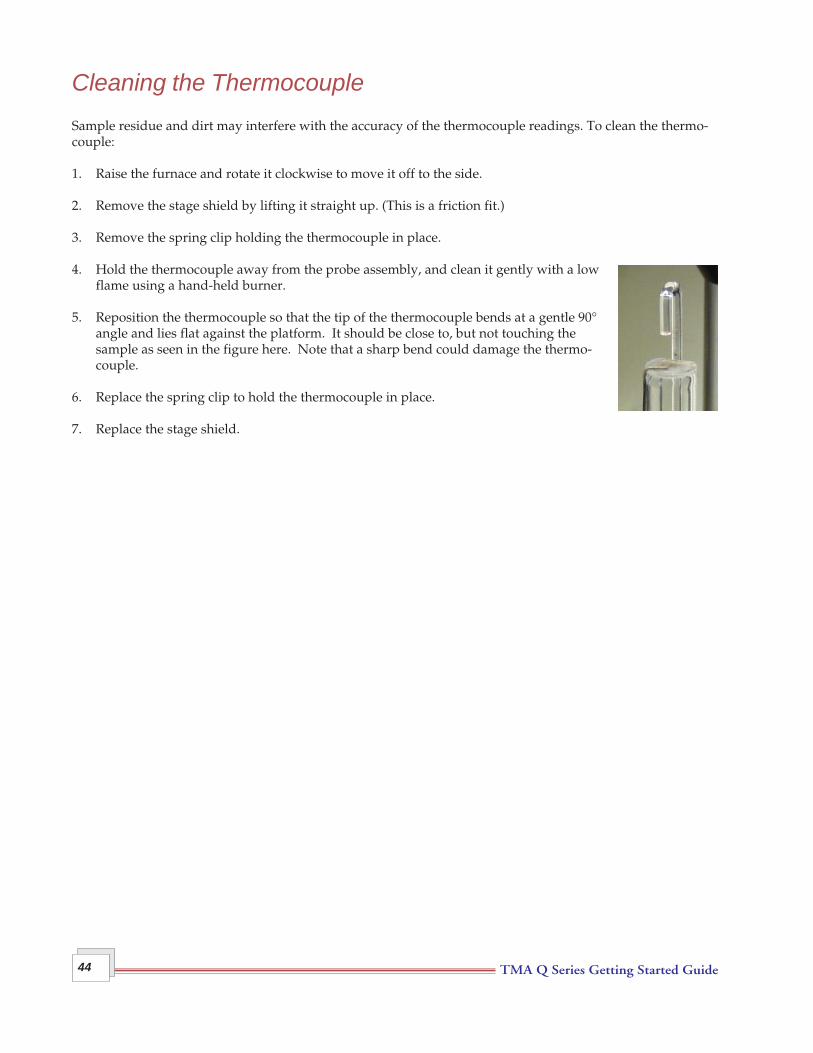
Cleaning the ThermocoupleSample residue and dirt may interfere with the accuracy of the thermocouple readings. To clean the thermo-couple:
1. Raise the furnace and rotate it clockwise to move it off to the side.
2. Remove the stage shield by lifting it straight up. (This is a friction fit.)
3. Remove the spring clip holding the thermocouple in place.
4. Hold the thermocouple away from the probe assembly, and clean it gently with a lowflame using a hand-held burner.
5. Reposition the thermocouple so that the tip of the thermocouple bends at a gentle 90°angle and lies flat against the platform. It should be close to, but not touching thesample as seen in the figure here. Note that a sharp bend could damage the thermo-couple.
6. Replace the spring clip to hold the thermocouple in place.
7. Replace the stage shield.
TMA Q Series Getting Started Guide 45
ReplacementsOccasionally, you may need to replace a broken or worn-out part of the TMA. Any replacements needed,other than those discussed in this manual, must be supplied and installed by qualified TA Instrumentsservice personnel. Call (302) 427-4050 for service.
Replacing the ThermocoupleYou may find that the need arises for a new thermocouple (PN 944344.902) as a result of normal wear andtear, accidental breakage, contamination of the thermocouple, etc.
Removing the Existing Thermocouple
To remove the thermocouple, you will need to perform the following steps:
WARNING: Whenever you remove the balance enclosure, make sure that the power isoff and the instrument is unplugged.
1. Raise the furnace and rotate it clockwise to move it off to the side.
2. Remove the stage shield by lifting it straight up. (This is a friction fit.)
3. Remove the spring clip holding the thermocouple in place.
4. Obtain the hex wrench from the accessory kit and remove the screws, two on each side that hold thebalance enclosure in place.
5. Slide the balance enclosure out and remove it.
6. Thread the thermocouple carefully down through the opening in the platform, and unplug it.
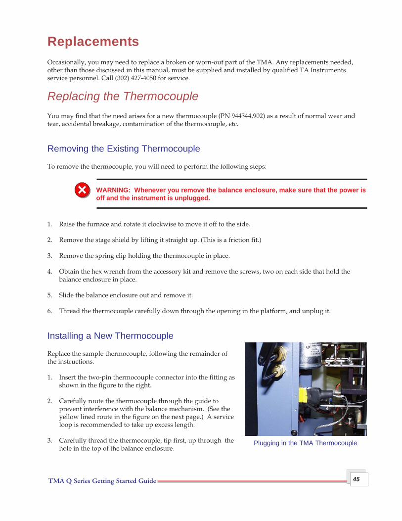
Installing a New Thermocouple
Replace the sample thermocouple, following the remainder ofthe instructions.
1. Insert the two-pin thermocouple connector into the fitting asshown in the figure to the right.
2. Carefully route the thermocouple through the guide toprevent interference with the balance mechanism. (See theyellow lined route in the figure on the next page.) A serviceloop is recommended to take up excess length.
3. Carefully thread the thermocouple, tip first, up through thehole in the top of the balance enclosure.
Plugging in the TMA Thermocouple

TMA Q Series Getting Started Guide46
4. Slide the balance enclosure into position.
5. Replace the screws, two on each side, that hold the balanceenclosure in place.
6. Reposition the thermocouple so that the tip of the thermo-couple bends at a 90° angle and lies flat against the sampleplatform. It should be close to, but not touching thesample.
7. Replace the spring clip to hold the thermocouple in place.
8. Place the stage shield on the stage, aligning the slot in thebottom over the thermocouple wire.
Threading the Thermocouple

TMA Q Series Getting Started Guide 47
Replacing Fuses
WARNING: Always unplug the instrument before you examine or replace the fuses.
Replacing the TMA Fuses
The TMA contains internal fuses that are not user serviceable. If any of the internal fuses blows, a hazard mayexist. Call your TA Instruments service representative.
The only fuses that you can replace yourself are the fuses locatedin the power entry module located at the rear of the instrument.To check or change these fuses:
1. Turn the instrument off and remove the power cord.
2. Insert a small screwdriver at the edge of the power entrymodule door and pry it open.
3. Insert the screwdriver on the edge of the fuse holder to pullit out of the instrument.
4. Remove old fuses and replace the fuses only with the typeand rating indicated on the instrument's rear panel.
5. Place fuse holder back into opening and push the door shut.
Fuse
Fuse Holder
Fuse
PowerEntryModule

TMA Q Series Getting Started Guide48
Replacement PartsReplacement parts for the TMA that are available from TA Instruments. See the table below when orderingparts.
Part Number Description
944200.901 Standard TMA Accessory Kitconsisting of:
944122.901 Expansion Probe Assembly944126.901 Penetration Probe Assembly944123.901 Macro-Expansion Probe Assembly944120.901 Sample Stage900902.901 Indium Calibration Standard940070.000 Aluminum Calibration Standard942057.000 Teflon® Demonstration Sample259537.000 Forceps259522.000 Set Weights203947.005 3/32 Hex Wrench269792.001 Wave Washers944205.001 Thermocouple Retainer
Optional Accessory Kits
944201.901 Film/Fiber Accessory Kit consisting of:
944121.901 Film/Fiber Sample Stage944128.901 Film/Fiber Probe Assembly941038.901 Vial Cleaved Aluminum Balls944047.901 Film Clamp Assemblies944144.001 Film Clamp Fixture269789.001 Jeweler’s Screwdriver (0.080 inch)269793.001 Film Clamp Screws (#0 - 80)944014.001 Automeasure Gauge
944202.901 Dilatometer Accessory Kit consisting of:
944124.901 Dilatometer Probe Assembly941143.000 Dilatometer Sample Vials941148.901 Vials Filling Medium941022.901 Vial Aluminum Calibration Standards
944203.901 Flexure Accessory Kit consisting of:
944127.901 Flexure Probe Assembly941054.000 Flexure Sample Platform
(table continued)

TMA Q Series Getting Started Guide 49
Part Number Description
944203.902 TMA Q400 EM Accessory Kit consisting of:
944127.901 Flexure Probe Assembly941054.000 Flexure Sample Platform945045.901 3-Point Bend Calibration Jig
944204.901 Parallel Plate Rheometer Accessory Kit consisting of:
943125.000 Rheometer Alignment Cages943126.000 Rheometer Parallel Plates900902.901 Indium Sample Kit943121.000 Pellet Press Base Screw943122.000 Pellet Press Cylinder head943123.000 Pellet Press Piston943124.000 Pellet Press Cylinder
944125.901 Hemispherical Probe Assembly945025.901 Heater Assembly for use with the TMA Q400205221.001 6.3 A Fuse205221.002 10 A Fuse944341.901 Protective Quartz Wafers for the TMA Stage944073.001 Washer disc silicon944072.001 Reservoir mass aluminum

TMA Q Series Getting Started Guide50

TMA Q Series Getting Started Guide 51
IndexA
accessories 12standard 12
expansion probes 12penetration probes 12
AIR COOL key 15
air cool lineinstalling 28
air source 28
Auto Measure Systemzeroing 39
B
balance enclosure 11installing 46removing 45
C
cableEthernet 31
cablesconnecting 26
Calibrate key 14
calibration 37cell constant 37force 36probe 30, 36zero force 36
calibration weights 36
cell constant calibration 37
cleaningprobe assembly 42stage 43thermocouple 44touch screen 42
components 11

TMA Q Series Getting Started Guide52
computerconnecting to Ethernet hub 31connecting to LAN 32
connectingcables 26gas lines 26
contamination 9
Control menutouch screen keys - QNX/Platinum 14
controllerdescription 11
cooling gas line 28
cooling gas port 27
D
Dilatometer Accessorydescription 21
dimensions 22
Display key 13
Display Menu 20
E
Electromagnetic Compatibility Standards 7
Ethernet cableconnecting computer to LAN 32
Ethernet hubconnecting to controller 31connecting to instrument 31
Ethernet port 26
Event port 26
experimentbasic steps 35procedure 38rejecting 41starting 41stopping 41
F
film/fiber probe 21
fittingcooling gas 28

TMA Q Series Getting Started Guide 53
Flexure Accessory 21operation 21
furnace assembly 11
fuses 47replacement for Voltage Configuration unit 25replacing on the TMA 47
G
gas linesconnecting 26
gasesuse of 27
H
hazardous products 9
Hemispherical Probe 21
I
installation 23 to 33voltage configuration unit 25
instrumentchoosing a location 24connecting to Ethernet hub 31grounding 24, 38inspecting 23installing 23 to 33lifting 9maintenance 42ports 26repacking 23replacement parts 48shutting down 34technical specifications 22unpacking 23
L
LAN 32
liquid nitrogensafety 10
location of instrument 24
M
maintenance 42

TMA Q Series Getting Started Guide54
Mass Flow Controller 27
Mass Flow Controller (MFC) 27
Measure Length key 40
Mechanical Cooling Accessory (MCA) 21
moisture 24, 38
N
networking 31
P
Parallel Plate Rheometer Accessory 21operation 21sample loading 21
Parallel Plate Rheometer AccessoryDescriptionsample preparation 21
parts 45, 48
ports 26Com 1 26Com 2 26cooling gas 27Ethernet 26Event 26
power cableinstalling 33
power entry module 33
power switch 33
primary function keys 18
probecleaning 42hemispherical 21installation 29, 30removal 30selection 30, 38standard 12, 30types 38
probe assemblydescription 11
probe setuphemispherical 21
Probe, standardremoval 30
probe types 38
TMA Q Series Getting Started Guide 55
Probes, expansioninstallation 30
Probes, penetrationinstallation 30
purge gas 27
purge gasesrecommended 22
purge line 27
Q
QNX/Platinumtouch screens 13
R
Regulatory Compliance 7
remote key. See also system key
repacking 23
replacement parts 45, 48
running experiments 38
S
safetylifting 9
Safety Standards 7
sampleloading 40preparation 40
sample thermocouplefunction 12
samplesdecomposition 9
SHUTDOWN key 15
shutting downinstrument 34
specifications 22
spring clipinstallation 29
stage 11cleaning 43installation 29

TMA Q Series Getting Started Guide56
stage nutinstallation 29
stage retainer ringinstallation 29
stage shieldinstallation 29, 46
startingexperiment 41instrument 34
status line 18
stoppinginstrument 34
stopping an experiment 41
T
TA Instruments service 45
technical specifications 22
thermal safety 10
thermocouplecalibration 37cleaning 44installing 45removing 45replacing 45
TMAdescription 11lifting 9probe types 38replacement parts 45replacing fuses 47touch screen 18touch screen - QNX/Platinum 13
TMA Q400touch screen - QNX/Platinum 13 to 17
touch screenCalibration Options - QNX/Platinum 17cleaning 42Control Menu 19Control Menu - QNX/Platinum 14Display Menu 20Display Menu - QNX/Platinum 16primary function keys 18primary function keys - QNX/Platinum 13QNX/Platinum 13

TMA Q Series Getting Started Guide 57
U
unpacking 23
V
voltage configuration unitinstalling 25
W
weight trayfunction 12
Z
Zero Length key 39

TMA Q Series Getting Started Guide58


![Skaffold - storage.googleapis.com · [getting-started getting-started] Hello world! [getting-started getting-started] Hello world! [getting-started getting-started] Hello world! 5](https://img.pdfslide.us/doc/110x75/5ec939f2a76a033f091c5ac7/skaffold-getting-started-getting-started-hello-world-getting-started-getting-started.jpg)