Embed Size (px)
Citation preview

TM5500/TM5800Thermal Design Guide
June 18, 2002

June 18, 2002 TM5500/TM5800 Thermal Design Guide
2
Crusoe™ Processor Model TM5500/TM5800Thermal Design GuideRevision 1.0
Revision History:
0.1 June 15, 2001 - First release version
1.0 June 18, 2002 - Removed “Preliminary”, added 867 and 900 MHz SKUs
Property of: Transmeta Corporation3940 Freedom CircleSanta Clara, CA 95054USA(408) 919-3000http://www.transmeta.com
The information contained in this document is provided solely for use in connection with Transmeta products, and Transmeta reserves all rights in and to such information and the products discussed herein. This document should not be construed as transferring or granting a license to any intellectual property rights, whether express, implied, arising through estoppel or otherwise. Except as may be agreed in writing by Transmeta, all Transmeta products are provided “as is” and without a warranty of any kind, and Transmeta hereby disclaims all warranties, express or implied, relating to Transmeta’s products, including, but not limited to, the implied warranties of merchantability, fitness for a particular purpose and non-infringement of third party intellectual property. Transmeta products may contain design defects or errors which may cause the products to deviate from published specifications, and Transmeta documents may contain inaccurate information. Transmeta makes no representations or warranties with respect to the accuracy or completeness of the information contained in this document, and Transmeta reserves the right to change product descriptions and product specifications at any time, without notice.
Transmeta products have not been designed, tested, or manufactured for use in any application where failure, malfunction, or inaccuracy carries a risk of death, bodily injury, or damage to tangible property, including, but not limited to, use in factory control systems, medical devices or facilities, nuclear facilities, aircraft, watercraft or automobile navigation or communication, emergency systems, or other applications with a similar degree of potential hazard.
Transmeta reserves the right to discontinue any product or product document at any time without notice, or to change any feature or function of any Transmeta product or product document at any time without notice.
Trademarks: Transmeta, the Transmeta logo, Crusoe, the Crusoe logo, Code Morphing, LongRun and combinations thereof are trademarks of Transmeta Corporation in the USA and other countries. Other product names and brands used in this document are for identification purposes only, and are the property of their respective owners.
This document contains confidential and proprietary information of Transmeta Corporation. It is not to be disclosed or used except in accordance with applicable agreements. This copyright notice does not evidence any actual or intended publication of such document.
Copyright © 2001-2002 Transmeta Corporation. All rights reserved.

TM5500/TM5800 Thermal Design Guide June 18, 2002
3
Chapter 1 Introduction and Overview ............................................................................................................... 11
1.1 Thermal Design Guide Overview ....................................................................................... 11
1.2 Thermal Device Problem....................................................................................................12
1.3 Power Dissipation in CMOS Microprocessors....................................................................13
1.3.1 Switching Power .........................................................................................................13
1.3.2 Short Circuit Power .....................................................................................................13
1.3.3 Leakage Power ...........................................................................................................14
1.4 Crusoe Processor Reference Documents..........................................................................15
Chapter 2 Thermal Management Fundamentals ..............................................................................................17
2.1 Thermal Engineering..........................................................................................................17
2.2 Thermal Energy Transfer - Conduction ..............................................................................18
2.2.1 Thermal Conductivity of Materials...............................................................................18
2.2.2 Fourier’s Law of Thermal Conduction .........................................................................20
2.2.3 Device Thermal Conductance.....................................................................................21
2.2.4 Device Thermal Resistance ........................................................................................22
2.3 Thermal Energy Transfer - Convection ..............................................................................22
2.4 Thermal Energy Transfer - Radiation .................................................................................24
2.5 Thermal/Electrical Analogs ................................................................................................27
2.6 Thermal Measurements .....................................................................................................28
2.6.1 Device Junction Temperature .....................................................................................28
2.6.2 Ambient Temperature..................................................................................................28
2.6.3 Calculating Thermal Resistance .................................................................................29
2.6.4 Airflow .........................................................................................................................29
2.7 Thermal Characterization of Electronic Packages .............................................................30
2.7.1 Junction-to-Case Thermal Resistance ........................................................................30
2.7.2 Junction-to-Board Thermal Resistance.......................................................................30
2.7.3 Junction-to-Air Thermal Resistance............................................................................31
2.7.4 Device Package Measurement Techniques................................................................32
Chapter 3 Crusoe Processor Thermal Specifications ......................................................................................33
3.1 Thermal Specifications.......................................................................................................33
3.2 Mechanical Specifications..................................................................................................34
3.3 Thermal Diode....................................................................................................................34
June 18, 2002 TM5500/TM5800 Thermal Design Guide
4
3.4 Thermal Model Examples...................................................................................................35
Chapter 4 Thermal Solution Design .................................................................................................................39
4.1 Thermal Solution Design Methodology ..............................................................................39
4.2 Package-Level Thermal Model...........................................................................................40
4.3 Conventional Thermal Solutions ........................................................................................41
4.3.1 Heatsinks.....................................................................................................................42
4.3.2 Heatpipes ....................................................................................................................44
4.3.3 Fans ............................................................................................................................44
4.3.4 Interface Materials.......................................................................................................45
4.3.4.1 Thermal Greases ......................................................................................47
4.3.4.2 Thermal Compounds.................................................................................47
4.3.4.3 Phase Change Materials...........................................................................47
4.3.4.4 Elastomers ................................................................................................47
4.3.4.5 Thermal Adhesives, Tapes, and Foils .......................................................48
4.3.5 Thermal Solution Attachment ......................................................................................48
4.4 Adaptive Thermal Solutions ...............................................................................................49
4.4.1 Thermal Throttling .......................................................................................................49
4.4.2 LongRun Advanced Thermal Management ................................................................50
Chapter 5 Thermal Solution Examples .............................................................................................................55
5.1 Thin-and-Light Notebook Thermal Design Example ..........................................................55
5.1.1 Environmental Temperature Limit Assumptions..........................................................55
5.1.2 Common Simulation Assumptions ..............................................................................55
5.1.3 Baseline Cooling Strategy ...........................................................................................58
5.1.3.1 Description ................................................................................................58
5.1.3.2 Specifics....................................................................................................59
5.1.3.3 Results ......................................................................................................59
5.1.3.4 Concerns...................................................................................................62
5.1.4 Variation A: Larger Heat-Spreader with Heatpipe .......................................................63
5.1.5 Variation B: Increased Copper Content in Multilayer PCB ..........................................66
5.1.6 Variation C: Remove Bosses and Attach Heat-Spreader to PCB ...............................67
5.1.7 Combination of Variations A, B, and C and 7.7 W Processor .....................................68
5.1.8 Summary of Component Temperatures for All Cooling Strategies..............................73
5.1.9 Conclusions.................................................................................................................74
Appendix A Thermal Terminology and Nomenclature .........................................................................................75
A.1 Terminology ........................................................................................................................75

TM5500/TM5800 Thermal Design Guide June 18, 2002
5
A.2 Nomenclature.....................................................................................................................77
A.2.1 Capital Letters .............................................................................................................77
A.2.2 Lower-Case Letters.....................................................................................................77
A.2.3 Greek Letters ..............................................................................................................78
A.2.4 Subscripts ...................................................................................................................78
Appendix B Thermal Conversions and Constants ..............................................................................................79
B.1 Thermal Conversion Factors ..............................................................................................79
B.2 Thermal Constants .............................................................................................................81
Appendix C Thermal Product Vendors ................................................................................................................83
C.1 Interface Materials..............................................................................................................83
C.2 Heatsinks and Fans............................................................................................................83
C.3 Heatpipes ...........................................................................................................................85
C.4 Thermal Measurement Instrumentation .............................................................................85
C.5 Thermal Design Services and Software.............................................................................86
Appendix D Thermal Engineering References ....................................................................................................87
D.1 Fundamentals of Heat Transfer..........................................................................................87
D.1.1 Conductive, Convective, and Radiative Heat Transfer ...............................................87
D.1.2 Convective Heat Transfer ...........................................................................................87
D.1.3 Radiative Heat Transfer ..............................................................................................87
D.1.4 Thermodynamics ........................................................................................................88
D.2 Thermal Measurement and Characterization Standards....................................................88
D.2.1 IEEE............................................................................................................................88
D.2.2 JEDEC ........................................................................................................................88
D.2.3 SEMI ...........................................................................................................................89
D.3 Printed Circuit Board Thermal Characteristics - IPC..........................................................89
D.4 Other Thermal Engineering References ............................................................................89
Appendix E Package Drawings ...........................................................................................................................91

June 18, 2002 TM5500/TM5800 Thermal Design Guide
6

TM5500/TM5800 Thermal Design Guide June 18, 2002
7
TABLE 2-1 Thermal Properties of Electronic Materials .................................................................19
TABLE 2-2 Emissivity of Electronic Materials................................................................................25
TABLE 3-1 Thermal Specifications................................................................................................33
TABLE 5-1 Typical Temperature Limits for Notebook Computers .................................................55
TABLE 5-2 Notebook Computer Thermal Solution Example Assumptions ...................................56
TABLE 5-3 Example Thermal Solution Design Specifics ..............................................................59
TABLE 5-4 Summary of Thermal Solution Example Simulation Results.......................................73
TABLE B-1 Thermal Conversion Factors ......................................................................................79
TABLE B-2 Thermal Constants......................................................................................................81

June 18, 2002 TM5500/TM5800 Thermal Design Guide
8

TM5500/TM5800 Thermal Design Guide June 18, 2002
9
FIGURE 3-1 Processor Thermal Model - Package Top and Bottom Heat Paths.............................37
FIGURE 3-2 Processor Thermal Model - Package Top Only Heat Path .........................................38
FIGURE 4-1 Package-Level Thermal Model ...................................................................................41
FIGURE 4-2 Performance Comparison - LongRun vs. Clock Throttling Thermal Management......52
FIGURE 4-3 Power Dissipation vs. Core Frequency-Voltage..........................................................53
FIGURE 5-1 Notebook Computer Simulation - External Geometry .................................................57
FIGURE 5-2 Notebook Computer Simulation - Internal Geometry ..................................................57
FIGURE 5-3 Baseline Cooling Strategy...........................................................................................58
FIGURE 5-4 Top Skin and Keycap Surface Temperatures..............................................................59
FIGURE 5-5 Bottom Skin Temperatures..........................................................................................60
FIGURE 5-6 Temperatures 6 mm Above PCB ................................................................................60
FIGURE 5-7 Temperatures Near Processor ....................................................................................61
FIGURE 5-8 Component Surface Temperatures .............................................................................62
FIGURE 5-9 Improved Heat-Spreader Geometry............................................................................63
FIGURE 5-10 Top Skin and Keycap Temperatures - Improved Heat-Spreader ................................64
FIGURE 5-11 Bottom Skin Temperatures - Improved Heat-Spreader...............................................64
FIGURE 5-12 Component Temperatures - Improved Heat-Spreader................................................65
FIGURE 5-13 Temperatures Near Processor - High Conductivity PCB ...........................................66
FIGURE 5-14 Modified Heat-Spreader Attachment Method..............................................................67
FIGURE 5-15 Bottom Case Temperatures - Modified Heat-Spreader Attachment............................68
FIGURE 5-16 Top Skin and Keycap Temperatures - 867 MHz (Top) and 7.7 W (Bottom) ................69
FIGURE 5-17 Bottom Skin Temperatures - 867 MHz (Top) and 7.7 W (Bottom)...............................70
FIGURE 5-18 Temperatures Near Processor - 867 MHz (Top) and 7.7 W (Bottom) .........................71
FIGURE 5-19 Component Temperatures - 867 MHz (Top) and 7.7 W (Bottom) ...............................72

June 18, 2002 TM5500/TM5800 Thermal Design Guide
10

TM5500/TM5800 Thermal Design Guide June 18, 2002
11
Chapter 1
Introduction and Overview
The Transmeta Crusoe processor model TM5500/TM5800 is based on fundamental technology innovations that provide x86 software compatibility, high performance, and low-power operation for mobile computing platforms. A TM5500/TM5800 Crusoe processor is composed of two major components: the packaged TM5500/TM5800 silicon chip (hardware), and the Code Morphing software, that together provide the functionality of an x86-compatible processor.
The Crusoe processor Code Morphing software and LongRun power management technologies incorporate intelligent adaptive processes that optimize performance and power consumption dynamically during software execution. Optimal low-power computer platforms incorporating Crusoe processors must be designed to accommodate the thermal characteristics and requirements of the Crusoe processor.
This document provides an overview of microprocessor-based mobile platform thermal design issues, with a particular emphasis on the unique operating characteristics and requirements of the Crusoe processor TM5500/TM5800 family. Thermal management solution examples applicable to systems based on Crusoe processor model TM5500/TM5800 are described.
1.1 Thermal Design Guide Overview
Chapter 1, Introduction and Overview of the TM5500/TM5800 Thermal Design Guide, describes the layout and content of the chapters and appendices in this document. The fundamental thermal management problem for microprocessor-based systems is outlined, followed by a section detailing the sources of power dissipation in CMOS microprocessors. Chapter 1 concludes with a list of Crusoe processor technical reference documents that may be useful in conjunction with the Thermal Design Guide.
Chapter 2, Thermal Management Fundamentals, provides technical information necessary for an understanding of thermal management principles. Information in this section includes thermal engineering concepts such as heat flow/thermal energy transfer by conduction, conductivity of materials, and thermal resistance. Thermal energy transfer by convection and radiation are also covered, and an electrical/thermal analog technique is described that provides the framework for device and system-level thermal models. Thermal measurement tools and techniques, calculation of thermal resistance, and thermal characterization of electronic device packages are described in later sections of Chapter 2.
Chapter 3, Crusoe Processor Thermal Specifications, provides device-specific thermal characteristics for the model TM5500/TM5800 processors, including thermal design power, package thermal resistance, and integrated thermal diode specifications. This chapter also provides example TM5500/TM5800 thermal models.
June 18, 2002 TM5500/TM5800 Thermal Design Guide
12
Chapter 4, Thermal Solution Design, provides a thermal solution design methodology, together with descriptions for a wide variety of thermal solution components. A detailed package-level thermal model for the Crusoe processor model TM5500/TM5800 is described, followed by a section on conventional thermal solutions. Conventional thermal solution components include a variety of passive heatsinks, heatpipes, fans, and interface materials. Thermal solution attachment mechanisms are also described. Chapter 4 concludes with a section on the latest approach to thermal management, Adaptive Thermal Solutions, highlighting the thermal design advantages of the Crusoe processor LongRun power management technology.
Adaptive thermal solutions are thermal solutions that utilize thermal feedback and control techniques, and intelligent algorithm-based adaptive thermal management. Thermal throttling techniques used in mobile computer systems are described and characterized. A new Crusoe processor-based adaptive thermal management strategy is presented that utilizes LongRun power management technology to regulate the thermal environment of the processor, while achieving maximum computational throughput and minimum overall energy consumption. This new thermal management solution offers the benefits of a lower-cost, lighter-weight solution with better thermal, processor performance, and battery-life characteristics than thermal throttling and conventional thermal management solutions.
Chapter 5, Thermal Solution Examples, includes a range of thermal solution examples for Crusoe processor model TM5500/TM5800-based systems. Detailed descriptions of system models, system and environmental assumptions, mechanical configurations, and computational fluid dynamic simulation results are provided.
The TM5500/TM5800 Thermal Design Guide concludes with a series of appendices with useful thermal design information and references. Appendix A, Thermal Terminology and Nomenclature, lists and defines common thermal engineering terms and nomenclature usage in this document. Appendix B, Thermal Conversions and Constants, contains tables of common thermal constants and conversions. Appendix C, Thermal Product Vendors, contains contact information for a variety of thermal management products. Appendix D, Thermal Engineering References, has an extensive list of thermal engineering information references. Appendix E, Package Drawings, has dimensioned mechanical drawings of the TM5500/TM5800 FC-CBGA package.
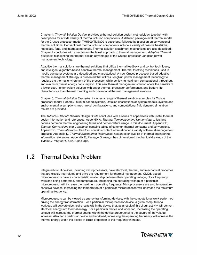
1.2 Thermal Device Problem
Integrated circuit devices, including microprocessors, have electrical, thermal, and mechanical properties that are closely interrelated and drive the requirement for thermal management. CMOS-based microprocessors have a characteristic relationship between their operating voltage, clock frequency, workload being performed, and temperature. Increasing the operating voltage of a particular microprocessor will increase the maximum operating frequency. Microprocessors are also temperature sensitive devices. Increasing the temperature of a particular microprocessor will decrease the maximum operating frequency.
Microprocessors can be viewed as energy transforming devices, with the computational work performed driving the energy transformation. For a particular microprocessor device, a given computational workload will activate electrical circuits within the device that, as a result of this circuit activity, will convert electrical energy into thermal energy. For a particular device and workload, increasing the operating voltage will increase the thermal energy within the device proportional to the square of the voltage increase. Also, for a particular device and workload, increasing the operating frequency will increase the thermal energy within the device in direct proportion to the frequency increase.

TM5500/TM5800 Thermal Design Guide June 18, 2002
13
As a result of these characteristic CMOS microprocessor properties, the demand for increasing performance has created an increasingly difficult thermal problem within today’s computer systems. As clock frequencies increase, and the amount of transistor circuits within microprocessors increases, the amount of thermal energy released within the microprocessor continues to increase with each processor generation. The thermal energy density within microprocessors is also increasing dramatically, creating severe thermal gradient issues within the silicon die and package substrate.
1.3 Power Dissipation in CMOS Microprocessors
There are three major components of power dissipation in CMOS microprocessors -switching power, short circuit power, and leakage power:
Ptotal = Pswitching + Pshort circuit + Pleakage (1-1)
1.3.1 Switching Power
Switching power dissipation in CMOS microprocessors is a function of device geometry (effective active capacitance), frequency of operation, and operating voltage.
Pswitching = (C • f • V2) / 2 (1-2)
where
C = effective active capacitance, Faradsf = switching frequency, HertzV = peak-to-peak voltage swing, Volts
Switching power dissipation results from the charging and discharging of the capacitance of transistor gates and interconnects during logic state changes. Switching power typically accounts for 70-90% of the total power dissipation in CMOS microprocessors. It is significant that switching power is a linear function of frequency and capacitance, and a quadratic function of voltage. Historically, operating frequency and device effective capacitance have been increasing with each microprocessor generation, while operating voltage has been decreasing with each process generation change. Overall, device switching power has been increasing dramatically with each microprocessor generation, in spite of the trend to lower operating voltage.
1.3.2 Short Circuit Power
Short circuit power dissipation, sometimes called crowbar power, in CMOS microprocessors results from the pull-up and pull-down transistors in CMOS logic gates being briefly and simultaneously on during state changes in output nodes. This creates a momentary near short-circuit condition from the supply rail to ground, with consequent power dissipation. Short circuit power dissipation typically accounts for 10-30% of the total power dissipation in CMOS microprocessors. Short circuit power dissipation is a function of operating voltage, effective short circuit current, and device specific characteristics:

June 18, 2002 TM5500/TM5800 Thermal Design Guide
14
Pshort circuit = Dshort circuit • Ishort circuit • V (1-3)
where
Dshort circuit = device-specific constantIshort circuit = effective short circuit current, AmpsV = peak-to-peak voltage swing, Volts
1.3.3 Leakage Power
Leakage power dissipation in CMOS microprocessors results from DC leakage currents, primarily gate transistor leakage currents. This power component is typically less than 1% of the overall device power dissipation. It is significant in very low-power states in power-managed CMOS microprocessors, however, and can become a dominant design consideration in extremely low-power, battery operated devices. Leakage power dissipation is a function of operating voltage and leakage current:
Pleakage = Ileakage • V (1-4)
where
Ileakage = leakage current, AmpsV = peak-to-peak voltage swing, Volts
It should be noted that leakage current is extremely sensitive to temperature, increasing exponentially with temperature increases. Also, leakage current typically increases 5x with each process generation change due to the decreasing thickness of the gate dielectric and reductions in the threshold switching voltage (Vt) with each process generation geometry shrink. The implication of these historical trends is that leakage power is expected to become a significant component of overall CMOS microprocessor power dissipation in future generation devices, and that limiting device temperature will be an important power management technique to keep leakage power under control.

TM5500/TM5800 Thermal Design Guide June 18, 2002
15
1.4 Crusoe Processor Reference Documents
The following documents should be used in conjunction with this guide:
• TM5500/TM5800 Data Book
• TM5500/TM5800 Package Specifications and Manufacturing Guide
• TM5500/TM5800 System Design Guide
• TM5500/TM5800 BIOS Programmer’s Guide
• TM5500/TM5800 Development and Manufacturing Guide

June 18, 2002 TM5500/TM5800 Thermal Design Guide
16

TM5500/TM5800 Thermal Design Guide June 18, 2002
17
Chapter 2
Thermal ManagementFundamentals
Thermal management is the engineering discipline of controlling the thermal operating characteristics and thermal environment within systems. In the context of microprocessor-based computer systems, thermal management involves control of the thermal environment within the computer system, and particularly the removal of excess thermal energy from the heat-generating and heat-sensitive components of the system. In most computer systems today, the microprocessor is not only one of the largest sources of thermal energy within the system, but also one of the most heat-sensitive system components. It has therefore become extremely important when designing microprocessor-based systems to carefully engineer the thermal features of the system to achieve reliable operation within the expected environmental conditions over the life of the system. To achieve this reliability, thermal management is used to ensure that each component in the system operates within its specified temperature limits.
2.1 Thermal Engineering
A knowledge of basic thermal engineering is required to understand the nature of thermal management and the design of thermal cooling solutions for microprocessor-based computer systems. The relevant areas of thermal engineering involve the transformation of electrical energy by an electrical device such as a microprocessor into thermal energy (heat), as discussed in the previous chapter, and the transfer of that thermal energy to the environment surrounding the device, discussed below.
From a thermodynamic standpoint, energy can be defined as the potential for change. Energy may manifest itself in many forms: macroscopic motion of an object, microscopic vibrations of particles, chemical bonds within molecules, electrical potential, etc. Thermal energy is energy that can directly affect the temperature of a material. For example, within an operating microprocessor, electrical circuits convert electrical energy to thermal energy, potentially causing the temperature of the microprocessor to increase. Heat transfer is the flow of thermal energy from one region to another within a system.
The thermal energy generated within, or heat transferred to, an electronic component can increase its temperature. However, if the temperature of a component exceeds the temperature of its surroundings, heat will be transferred from the component to the surroundings. Conversely, if the temperature of the surroundings is higher than the temperature of the component (i.e. if the component does not heat itself hotter than its surroundings), heat will be transferred from the surroundings to the component. If the rate of heat transfer to the surroundings balances the rate of thermal energy generation (power dissipation) of the component, no extra thermal energy can be stored within the component. Therefore, the temperature of the component will not change. This is known as a steady state condition.
Heat generation by a CMOS microprocessor is a function of the processor core operating frequency, peak operating voltage, total effective device capacitance, leakage and short circuit currents. There are three modes by which heat can be transferred to or from a component such as a microprocessor -
June 18, 2002 TM5500/TM5800 Thermal Design Guide
18
conduction, convection and radiation. These three heat transfer modes, and their contributions to heat transfer from a microprocessor in a computer system, are explained in the following sections.
2.2 Thermal Energy Transfer - Conduction
The heat transfer between two objects in direct contact with each other is through molecular or atomic interactions (e.g. vibrations, collisions, electron translation). A high temperature object has more energetic molecules, atoms and electrons compared to a low temperature object. The transfer of this thermal energy from high energy objects to low energy objects is termed ‘conductive heat transfer’, or just ‘conduction’. Thermal conduction is the primary method of heat transfer within solids. Heat conduction involves the transfer of kinetic thermal energy by way of molecular and electron interactions within a material, and not involving macroscopic motion of the material. Thermal conduction through non-metallic (electrically insulating) solids is primarily due to lattice vibrations. Thermal conduction through metallic solids involves lattice vibrations and free electron energy exchange. Electron-based thermal energy transfer is very similar to electric charge transfer, and good electrical conductors are also good thermal conductors.
The packed molecular structure of solids provides the mechanical-electrical framework for thermal conduction. Stationary fluids (still liquids and gases) also exhibit the same mechanism of conductive heat transfer, but less so than solids due to the decreased degree of molecular interaction inherent in the fluid state. Liquids therefore typically have lower thermal conductivity than solids. The heat transfer from a high temperature region to a low temperature region of a still fluid is due to the high energy molecules colliding with those in the low temperature region of the medium. Similarly, gases have even less molecular interaction than liquids and solids, and have correspondingly very low thermal conductivity.
Conduction is the only mechanism of heat transfer within the package of a microprocessor. Heat generated by the silicon die (junction) conducts to the ceramic substrate through the solder balls under the die (for a flip-chip ceramic ball-grid array, FC-CBGA, package as used in the TM5500/TM5800) and to the heat-spreader through epoxy. Conduction between the substrate and printed circuit board occurs through the solder balls under the substrate (again, for a BGA package). If a heatsink is mounted on top of the heat-spreader in the package, heat may conduct into this heatsink through an interface material. For more information on TM5500/TM5800 package specifics and heatsinks see the following chapters.
2.2.1 Thermal Conductivity of Materials
Thermal conductivity is a property of matter that describes a material’s ability to transfer thermal energy. Thermal energy is conducted through a material at a rate proportional to the area normal to the heat flow and to the temperature difference (thermal gradient) along the heat flow path. Thermal conductivity is defined as the material-specific proportionality constant for this thermal energy transfer relationship (Fourier’s Law):
Q = k • A • dT/dx (2-1)
where
Q = heat flow (normal to the cross-sectional area of heat transfer), Wk = thermal conductivity of medium, W / (m • °K) or W / (m • °C)A = cross-sectional area of medium normal to heat flow path, m2

TM5500/TM5800 Thermal Design Guide June 18, 2002
19
dT/dx = temperature gradient, °K / m or °C / mT = temperature of medium, °K or °Cx = position along the medium, m
Thermal conductivity indicates how easily heat flows through a material as a result of a temperature difference across the material.
k = - q / (dT/dx) (2-2)
where
k = thermal conductivity, W / (m • °K) or W / (m • °C)q = Q / A = heat flux, W / m2
dT/dx = temperature gradient (steady state), °K / m or °C / m
The negative sign indicates that heat flows from higher temperature regions to lower temperature regions. Larger values of thermal conductivity indicate more heat flow for a given area and temperature differential than low thermal conductivity values. Good heat conductors have high thermal conductivity and good heat insulators have low thermal conductivity. At room temperature (300°K), the thermal conductivity of copper, a good conductor, is approximately 400 W/m•°K. At sea level and room temperature, the thermal conductivity of air, a poor conductor, is 0.026 W/m•°K.
Thermal conductivities for different materials are measured using various direct and indirect methods. Tables for these thermal conductivity values are available in the thermal engineering literature (see Appendix D, Thermal Engineering References). The table below lists some thermal properties, including thermal conductivity (k), of materials commonly used in microelectronics.
TABLE 2-1 Thermal Properties of Electronic Materials
Material Thermal ConductivityW / (m•°K)
Thermal Coefficient of Expansionppm / °K
Densityg / cm3
Alumina, 96% 21 6.5 3.8Alumina, 99.5% 37 6.8 3.9Aluminum, 99.99+% 237 23 2.702Aluminum, 1100H18 218Aluminum, 6063 T6 201Aluminum, 6061 T0 173 23.4 2.71Aluminum, 6061 T6 156 23.6 2.72Aluminum, 5052 139Aluminum, 2024 and 7075 120-130Beryllium oxide, 99.5% (temp dep) 250 7.5 2.9Ceramic, cofired multilayer 15 6-6.5Copper, 99.99% 386 16.5 8.96Diamond, type IIA 2000Diamond, type IIB 1300Diamond, film 100-1200 3.5

June 18, 2002 TM5500/TM5800 Thermal Design Guide
20
2.2.2 Fourier’s Law of Thermal Conduction
Conductive heat transfer is governed by Fourier's Law, as stated previously in equation (2.1), and again below in equation (2.3) for the case of heat flow in one-dimension. As the formula indicates, conductive heat flow (Qcond) is proportional to the temperature gradient (dT/dx) and the area available for heat transfer (A), as well as the thermal conductivity of the medium (k).
Qcond = k • A • dT/dx (2-3)
Note that if thermal conductivity is constant over a length (L) of material, the equation above can be written as:
Qcond = k • A • ∆T/L (2-4)
Epoxies 0.17-1.0 10-35Epoxy fiberglass laminate, FR-4 0.8 (x, y)
0.3 (z)16-20 (x, y)50-70 (z)
1.8-2.0
Epoxy, silver fill 2-2.5 45 < 88°C20 > 88°C
Gold, 99.99+% 318 14.3 18.9Invar 13.8 1.33 8.13Kovar 16.3 5.3 8.36Magnesium 157 1.74Manganese 7.8Silicon, 99.5-99.95% 150 2.8 2.33Silicon carbide, SiC 270 3.7 3.2Silicon dioxide, SiO2 (vitreous) 0.5-2 0.5 2.2
Silicon nitride, SiN 27 2.3Silicon nitride 3-4,Si3N4 (alpha) 80 (single xtal)
10-33 (h-press)3 3.2
Silver, 99.99% 427 19.2 10.5Solder, 95% Pb / 5% Sn 32.3 28 11Solder, 90% Pb / 10% Sn 36 28Solder, 40% Pb / 60% Sn 50 24.2 9.29Teflon 0.25 20-120Thermal grease (depends on filler) 0.1-1.5
TABLE 2-1 Thermal Properties of Electronic Materials
Material Thermal ConductivityW / (m•°K)
Thermal Coefficient of Expansionppm / °K
Densityg / cm3

TM5500/TM5800 Thermal Design Guide June 18, 2002
21
where ∆T is the temperature difference between one end of the material and the other.
Heat flow is considered positive in the direction of decreasing temperature. Note that the area normal to the heat flow path and the temperature gradient are defined at the same point (x). Thermal conductivity, as described previously, is the proportionality constant for the energy transfer relationship. Thermal conductivity for a given material varies somewhat with temperature, depending on the material. Most thermal engineering problems for microprocessor-based systems operate within such a narrow temperature range that the variation of thermal conductivity with temperature may be safely ignored, with only minimal impact on thermal solution design accuracy.
In the more general three-dimensional case, Fourier’s Law can be extended to provide similar results. Under the assumptions of constant thermal conductivity and steady state conditions within a three-dimensional object, the following relationship holds true:
∆T = T2 - T1 = (Q • L) / (k • A) (2-5)
where
∆T = T2 - T1 = the temperature difference across the object, °K or °CQ = the thermal energy of a heat source, WL = the length, mk = thermal conductivity of medium, W / (m • °K) or W / (m • °C)A = cross-sectional area of medium normal to heat flow path, m2
Thermal resistance can be defined as:
θ = L / (k • A) (2-6)
From the preceding two equations, thermal resistance can also be expressed as:
θ = L / (k • A) = ∆T / Q (2-7)
2.2.3 Device Thermal Conductance
The thermal conductance of an object or device is a measure of the ease with which heat is transferred through the object or device. The greater the thermal conductance, the more readily is heat transferred. Thermal conductance is defined as:
λdevice = P / ∆T (2-8)
where
λdevice = device thermal conductance, W / °CP = device power dissipation, W∆T = temperature rise in device, °C
June 18, 2002 TM5500/TM5800 Thermal Design Guide
22
2.2.4 Device Thermal Resistance
The thermal resistance of an object or device is the inverse of thermal conductance, and is a measure of the temperature differential across the object or device resulting from power dissipated in the object. The greater the thermal resistance, the less readily is heat transferred. Thermal resistance is defined as:
θdevice = ∆T / P (2-9)
where
θdevice = device thermal resistance, °C / W∆T = temperature rise in device, °CP = device power dissipation, W
2.3 Thermal Energy Transfer - Convection
If an object at one temperature is in contact with a moving fluid at a different temperature, heat will be transferred between that object and the fluid. A cold fluid flowing over a hot object receives thermal energy, through conduction from the object's surface, and carries that energy away from the object, by the bulk fluid motion. The reverse process happens when hot fluid comes in contact with a cold object. This mode of heat transfer is called ‘convective heat transfer’, or just ‘convection’. There are two different types of convective heat transfer - forced convection and natural convection. In forced convection, the fluid motion is generated by an external means, such as a fan or pump. In natural convection, temperature gradients within the fluid result in density differences. Lower density regions are buoyant, relative to higher density regions, and consequently move upwards, opposite the pull of gravity (hot air rises).
In the context of thermal management for microprocessor systems, the fluid of interest is air. The transfer of thermal energy from computer systems to ambient air is the most common method of cooling these systems. Even where heat conduction is employed within a processor thermal solution, ultimately the heat being removed from the system must be transferred to the ambient air, and convection is the means for transferring the heat removed from the system to the surrounding air.
Inside the computer system, after heat has conducted to the surface of a microprocessor package, heatsink, or circuit board, some of the heat may then be transferred to a surrounding fluid via convection. In the case of cool air being pushed or pulled over the surface by a fan, forced convection is typically the dominant mode of heat transfer. If there is no forced air velocity present, both natural convection and radiation may become important for transferring heat from the surface.
The thermal energy transferred by convection is proportional to the temperature difference between the object and the fluid (∆T), and the area available for heat transfer (A). Convective cooling is sometimes referred to as Newtonian cooling, and is described by Newton's Law of cooling:
Qconv = hconv • A • ∆T (2-10)
where
Qconv = convective heat transfer rate, Whconv = convective heat transfer coefficient, W / (m3 • °K) or W / (m3 • °C)

TM5500/TM5800 Thermal Design Guide June 18, 2002
23
A = surface area, m2
∆T = temperature differential between fluid and surface, °K or °C
The convective heat transfer coefficient is a positive value that depends on:
• Flow characteristics - high speed turbulent flows have higher convective heat transfer coefficients than low speed laminar flows. Also, convective heat transfer coefficients for forced convection flows are generally higher than those for natural convection flows.
• Fluid properties - liquid flows have higher heat transfer coefficients compared to similar gas flows.
• Geometry of the surface and the flow.
• Acceleration of gravity in natural convection flows.
Because of the complexity of determining convective heat transfer coefficients, analytical solutions to convective thermal problems are considerably more difficult than conductive thermal problems. In practice, the heat transfer coefficient is often approximated with empirically determined values based on the type of problem being solved. In air cooling of a typical electronic component, the convective heat transfer coefficient is about 7-50 W/m2 • °C in forced convection flows, and about 4-10 W/m2 • °C in natural convection flows. For details on determining heat transfer coefficients for specific environments, see the convective heat transfer references in Appendix D, Thermal Engineering References.
For most practical thermal solution design situations, the average surface temperature and average heat transfer coefficient are used for solving the convective equations. Under these assumptions, the preceding equation can be expressed as:
∆T = Qconv / (hconv • A) (2-11)
By analogy to the case of conduction and conductive thermal resistance, a comparable convective surface thermal resistance θconv can be defined as:
θconv = 1 / (hconv • A) (2-12)
These relationships define the heat transfer coefficient hconv as a proportionality constant for a convective surface indicating the heat transferred through a temperature difference per unit area of the surface. As mentioned above, the heat transfer coefficient actually depends on surface characteristics and geometry, temperature, fluid velocity, viscosity, and density.
Convective cooling is typically classified into two categories, forced convection and natural convection, depending on the relative velocities of the fluid and the object being cooled. Natural convection, sometimes referred to as free convection, describes the case where the fluid and thermal object are at rest relative to each other. Thermal energy is transferred between the fluid and the object at the surface of the object by direct contact. Since the particles of the fluid are free to move, energy transferred to the particles increases their internal energy, and thus their temperature, and causes a decrease in their density. Buoyant forces then cause the particles to move to regions of lower density and temperature in the fluid. By this means thermal energy is transferred from the object to the fluid (or vice versa). The fluid-to-object interface builds up a boundary layer of heated (or cooled) particles in the fluid. The motion of particles in natural convection is due to density differences within the fluid resulting from temperature differences, and no external force is applied to move the fluid or object relative to each other. For the case of natural convection, the convection heat transfer coefficient (hnconv) is given by:
hnconv = D • E • (∆T0.25 / L0.25) (2-13)
where

June 18, 2002 TM5500/TM5800 Thermal Design Guide
24
hnconv = natural convection heat transfer coefficient, W / (cm3 • °K) or W / (m3 • °C)D = constant, dependent on air propertiesE = constant, dependent on surface configuration∆T = temperature difference between object surface and fluid, °K or °CL = characteristic length of object surface, m
Forced convection relies on the application of external force to move the fluid and thermal object relative to each other. Typically the fluid is driven by a fan or pump to flow past the object being cooled or heated. The heat transfer mechanism in forced convection is the same as natural convection, surface transfer of thermal energy from object to fluid by direct contact. For the cases of interest for mobile computing, low-power fans are often used to circulate ambient air past a metal heatsink to remove heat from the heatsink attached to the electronic devices. Fans are described in a subsequent chapter, and are not discussed further in this section. For the case of forced convection, the convective heat transfer coefficient (hfconv) is given by:
hfconv = B • (V0.75 / L0.25) (2-14)
where
hfconv = forced convection heat transfer coefficient, W / (cm3 • °K) or W / (m3 • °C)B = constant, dependent on fluid properties and surface configurationV = linear velocity of fluid, m / secL = characteristic length of object surface in direction of flow, m
This relationship shows that the linear velocity of the forced convection fluid is an important factor in determining the heat transferred in a given thermal management configuration. As the velocity of the fluid increases, the flow characteristics change from laminar to turbulent flow. Laminar flow describes the condition where fluid particles follow a smooth continuous path, and turbulent flow introduces instabilities and eddies into the flow pattern, resulting in greater mixing of the fluid particles. For air as the fluid, the transition from laminar to turbulent flow occurs at approximately one meter per second. Turbulent flow generally results in greater heat transfer properties, though at the cost of greater energy required to drive the flow. Commercially available heatsinks are fully characterized for natural (zero air velocity) and forced air convection, at a variety of airflow rates.
2.4 Thermal Energy Transfer - Radiation
If there is no direct contact between two objects at different temperatures, and there is no interfering medium, thermal energy can still be transferred by radiation and absorption of electromagnetic waves. This mode of heat transfer is called ‘radiative heat transfer’, or just ‘radiation’. Heat transfer by radiation does not require contact between the objects, and does not require any material transport medium at all. Radiation, therefore, can be used to transfer heat between objects even in a vacuum. This is the thermal energy transfer mechanism that brings heat to earth from the sun, and accounts for the heat felt when standing near campfires and fireplaces. Radiation is essentially a surface-related effect, in that the vast majority of electromagnetic radiation emission and absorption takes place at the surface of objects.
A black surface absorbs the visible light that falls on it, and reflects very little light away. Similarly, a thermal black body is defined as a surface that absorbs all the thermal radiation that reaches its surface and reflects none. Objects also emit radiation in relation to their surface temperature. Materials that are good absorbers of thermal radiation are also good emitters of thermal radiation. Real materials do not have the surface characteristics of ideal black bodies, and thus have emissive and absorptive

TM5500/TM5800 Thermal Design Guide June 18, 2002
25
characteristics somewhat different than ideal black bodies. The net amount of radiative heat transfer between two objects is a complicated function of their temperatures, surface properties, and orientations relative to each other.
The emissivity (ε) of an object surface is defined as the ratio between the radiated flux (E) emitted by the object surface and the ideal radiated flux (Eb) emitted by a black body at the same temperature:
ε = E / Eb (2-15)
The actual emissive ability of a real surface is always less than Eb. The table below shows the emissivities of materials commonly used in microelectronics. An ideal black body would have an emissivity of 1, and a perfect reflector an emissivity of 0. Notice that aluminum, commonly used for heatsink thermal solutions in computer applications, has an emissivity of 0.04 in the polished state, and 0.80 in the black anodized state. Aluminum heatsinks are almost always black anodized because the high emissivity provides radiative cooling as well as the more commonly discussed conductive and convective cooling effects.
The rate of emission of radiative thermal energy is defined as:
R = Qrad / A (2-16)
where
R = rate of emission of thermal energy from surface, W / m2
Qrad = radiative heat transferred, WA = radiating surface area, m2
TABLE 2-2 Emissivity of Electronic Materials
Material Emissivity (ε)White alumina (98%) 0.88Beryllia 0.87Anodized aluminum 0.80Thick oxide-coated copper 0.78Oxidized steel 0.78Rolled sheet steel 0.55Stainless steel - alloy 316 0.28Dull nickel plate 0.11Machined copper 0.07Rough aluminum 0.06Kovar 0.05Polished aluminum 0.04Bright tin 0.04Gold 0.04Polished copper 0.03Silver 0.02Polished silver 0.02

June 18, 2002 TM5500/TM5800 Thermal Design Guide
26
The rate of emission of radiative thermal energy from the surface of an object is given by:
R = ε • σ • T4 (2-17)
where
R = rate of emission of thermal energy from surface, W / m2
ε = surface emissivity, Joules / (sec • m2)σ = Stefan-Boltzmann constant, 5.670 x 10⁻⁸ W / (m2 • °K4)T = temperature of surface, °K
Solving these two relationships for the heat transferred Qrad:
Qrad = ε • σ • A • T4 (2-18)
The radiative heat transfer between two ideal black body surfaces (ε = 1), one completely enclosed by the other, is given by:
Qrad = A • σ • (T14 - T24) (2-19)
where
Qrad = radiative heat transferred, WA = radiating surface area, m2
σ = Stefan-Boltzmann constant, 5.670 x 10⁻⁸ W / (m2 • °K4)T1 = temperature of hot body surface, °KT2 = temperature of cold body surface, °K
For real (non-black body) object surfaces, ε < 1 and the radiation heat transfer is:
Qrad = Fs • A • ε • σ • (T14 - T24) (2-20)
where
Fs = view factor
Fs is sometimes called the shielding factor, and is a measure of the visibility of the emitter by the absorber. The view factor can have a value ranging from 0 to 1, with a value of zero indicating no radiative path between emitter and absorber, and the maximum value of one indicating 100% radiative coupling between emitter and source.
The previous equation can be rewritten as:
Qrad = hrad • A • ∆T (2-21)
which is similar to Newton's Law of cooling for convective heat transfer rate. In this equation,
hrad = Fs • ε • σ • (T12 + T22) • (T1 + T2) (2-22)
is called the radiation heat transfer coefficient.
It is especially important to consider radiation as a means of heat transfer from a processor where there is no forced convection. Radiation is also important in high altitude applications since the lower density air at high altitude cannot carry as much heat for convective cooling.

TM5500/TM5800 Thermal Design Guide June 18, 2002
27
2.5 Thermal/Electrical Analogs
Thermal systems can often be modeled and explained by analogy to simple electrical circuits. Temperature difference across a thermal device (∆T) is analogous to voltage drop (V) across an electrical device. Heat flow (Q) in a thermal device is analogous to current flow (I) in an electrical device. Thermal resistance (θ) is analogous to electrical resistance (R), and thermal conductance (λ) is analogous to electrical conductance (σ).
The thermal energy transfer equations presented previously show that the heat transfer rate in a thermal system is proportional to an applied temperature difference. If the temperature difference is considered as the driving potential for the heat transfer, these equations can be written as:
Q = (T1 - T2) / θ (2-23)
which is similar to the Ohm's law for an electric circuit. θ (°K/W or °C/W) is called the thermal resistance. The thermal resistance analogy, equation (2-23), is appropriate for steady state heat transfer. The equations below provide the appropriate definitions of thermal resistance for the three modes of heat transfer. For 1-dimensional conduction (constant k):
θcond = L / (k • A) (2-24)
for convection:
θconv = 1 / (hconv • A) (2-25)
for radiation:
θrad = 1 / (hrad • A) (2-26)
The advantage of the resistance analogy is that, along with rules to combine series and parallel thermal resistances, it can be used to combine all the heat transfer paths between a location at temperature T1 and a location at temperature T2 into a single equivalent thermal resistance.
When thermal conductors are stacked in layers or attached end-to-end, the equivalent total thermal resistance, as in the electrical resistance case, is simply the sum of the individual thermal resistances of the series thermal elements. For n thermal resistances in series, the equivalent thermal resistance (θseries) is given by:
θseries = θ1 + θ2 + θ3 + ... + θn (2-27)
The temperature at a specific thermal interface within a series of connected thermal elements is given by:
Tj, j-1 = Theatsink + Q • Σ θj, j-1:hs (2-28)
where
Tj, j-1 = the temperature at the interface of layers j and j-1Theatsink = the temperature of the heatsinkQ = the thermal energy of the heat sourceΣ θj, j-1:hs = the sum of thermal resistances from interface of layers j and j-1 to the heatsink

June 18, 2002 TM5500/TM5800 Thermal Design Guide
28
As in the case of electrical resistance elements in parallel, combinations of parallel thermal elements are quite common in thermal systems. Whenever multiple heat flow paths exist from a thermal energy source, each path may be viewed as a thermal element with an associated thermal resistance. For n thermal paths (parallel thermal elements), the equivalent thermal resistance (θparallel) is given by:
1/θparallel = 1/θ1 + 1/θ2 + 1/θ3 + ... + 1/θn (2-29)
2.6 Thermal Measurements
Evaluation and characterization of thermal solutions requires careful measurement of the thermal device and the thermal environment of that device. This section focuses on measurement tools and techniques used in the analysis and testing of thermal management solutions for portable computing devices. Temperature measurement is the most fundamental thermal management tool, and techniques for measuring the temperature of microprocessor devices, heatsinks, and ambient temperature are described. Because convective thermal management solutions involve airflow as an integral component of the solution, tools for airflow measurement are also covered in this section.
2.6.1 Device Junction Temperature
The preferred method for measuring the junction temperature (Tj) of model TM5500/TM5800 processors is through the on-die thermal diode, in combination with a Maxim temperature sensor device. It is strongly recommended that every TM5500/TM5800 processor system incorporate a temperature sensor device to monitor the processor junction temperature and control a thermal management solution to ensure operation of the processor within the specified device temperature operating limits. It is also strongly recommended that an over-temperature safety shutdown system, independent of the functional operation of the processor, be a part of every TM5500/TM5800 processor-based system.
For design testing and temperature sensor device calibration and verification, the TM5500/TM5800 processor junction temperature (Tj) can be measured at the surface of the exposed silicon die. For thermocouple temperature probes, the point of measurement is usually taken at the center of the exposed die area. Direct attachment of a thermocouple probe to the die surface can cause damage to the device if not done with extreme care. Since some form of thermal solution is usually required for a reliable system design, it is recommended that a thermocouple probe be inserted into a hole drilled into the thermal solution such that the probe tip comes into direct thermal contact with the center of the exposed die surface at the attach point of the thermal solution to the processor. Use of thermal grease at the probe tip is highly recommended. The most accurate means of measuring the device junction temperature is with a thermal imaging device (camera). This technique is preferred for designs that do not require a view-obstructing thermal solution.
2.6.2 Ambient Temperature
Ambient temperature for the purposes of TM5500/TM5800 processor thermal solution design is the temperature of the in-system environment immediately adjacent to the processor. This environment can include nearby components, the printed circuit board, the air surrounding the processor, and the system

TM5500/TM5800 Thermal Design Guide June 18, 2002
29
case. With respect to thermal solution design, the significant ambient environment is the thermal sink into which heat from the device being cooled is transferred.
Depending on the thermal solution chosen for a system, the relevant ambient environment, and the method for measuring the ambient temperature varies somewhat. For systems using heatsinks and fans as the primary thermal solution, the air temperature at the input to the fan is often the relevant ambient temperature. For systems that use conductive heat transfer (heat-spreaders) as the thermal solution, the case temperature of the device is usually the ambient temperature. If the system uses a multi-stage thermal solution, or multiple types of thermal solutions, there can be more than a single relevant ambient temperature. An example is a system that uses heat-spreaders to transfer heat to the case, as well as an over-temperature fan.
2.6.3 Calculating Thermal Resistance
Using the temperature measurements of the TM5500/TM5800 processor junction temperature and ambient temperature, the junction-to-ambient thermal resistance can be easily calculated using the thermal resistance formula above. Recall that device thermal resistance is given by:
θdevice = ∆T / P (2-30)
For junction-to-ambient thermal resistance, the temperature rise (∆T) is given by the difference between the junction temperature (Tj) and the ambient temperature (Ta), ∆T = Tj - Ta, and:
θja = (Tj - Ta) / P (2-31)
where
θja = device junction-to-ambient thermal resistance, °C / WTj = device junction temperature, °CTa = device environment ambient temperature, °CP = device power dissipation, W
2.6.4 Airflow
Convection cooling using moving air is a significant component of many TM5500/TM5800 processor thermal solutions. The velocity of the air moving across components can be measured using an air velocity measurement device called an anemometer. The principle of operation of an anemometer is that two temperature sensors are placed in-line in the airflow stream. One temperature sensor measures the temperature of the airstream. The other sensor is connected to a heater and placed in a feedback loop that maintains a constant temperature difference above the temperature of the airstream. The airstream removes heat from the heated element, requiring more heater current to maintain the required temperature differential. The electrical current to the heating element is proportional to the moving air mass velocity, and is used to indicate the air velocity on the anemometer output.

June 18, 2002 TM5500/TM5800 Thermal Design Guide
30
2.7 Thermal Characterization of Electronic Packages
The heat generated by a microprocessor may go through many paths to reach the ambient surroundings. A thorough package-level thermal analysis of a processor includes detailed modeling of all these paths, on a simple test board in a controlled environment. However, in a real world application, the package containing the processor may be mounted on a board with many other components, in a system with many other boards. It becomes computationally difficult to model processors in detail when board-level or system-level thermal analysis is also required. The resistance analogy is a powerful tool to characterize the thermal performances of processors. Detailed package-level thermal analyses and/or experimental measurements are used to obtain appropriate thermal resistances for a processor. These thermal characterization parameters can then be used in board-level and system-level thermal analyses of electronic equipment, reducing the complexity of the analysis. Some standard parameters are explained in the following sections.
2.7.1 Junction-to-Case Thermal Resistance
One path through which the heat generated inside a processor is dissipated to the ambient is from the silicon chip to the case of the processor, and then from the case to the ambient fluid. The conduction paths from the chip to the case may include the chip itself, underfill, heat-spreader, solder balls, substrate, etc. If the case and the chip are assumed to be at uniform temperatures, an equivalent thermal resistance can be determined between the chip and the package case of the processor. This is called junction-to-case thermal resistance (θjc), and is defined as:
θjc = (Tj - Tc) / Pjc (2-32)
where
θjc = device junction-to-case thermal resistance, °C / WTj = device junction temperature, °CTc = device case temperature, °CPjc = device heat flow rate from the junction to the package case, W
Some packages, such as the TM5500/TM5800 processor's flip-chip ceramic BGA (FC-CBGA), are ‘lidless’ or ‘unencapsulated’ (i.e. the silicon die generating the power is exposed). In this case, θjc is simply the conductive thermal resistance through the silicon die, generally less than 0.1 °C/W.
2.7.2 Junction-to-Board Thermal Resistance
The other key path for heat removal from a microprocessor is from the silicon die to the printed circuit board, and then from the board to the ambient fluid. For a surface mounted package, the first stage of this heat path involves conduction from the die into the lead frame or substrate of the package. Conduction then occurs through the leads, solder balls or solder columns of the package to the contact pads on the surface of the board. Assuming the die and board contact points are at uniform temperatures, an equivalent thermal resistance can be determined between the die and the board. This is called junction-to-board thermal resistance (θjb) and is defined as:

TM5500/TM5800 Thermal Design Guide June 18, 2002
31
θjb = (Tj - Tb) / Pjb (2-33)
where
θjb = device junction-to-board thermal resistance, °C / WTj = device junction temperature, °CTb = printed circuit board temperature, °CPjb = device heat flow rate from the junction to the PCB surface, W
In reality, the board temperature under a package may vary somewhat depending on the conductivity of the substrate or lead frame and location of thermal vias and thermal solder balls or pads under the die. For BGA packages, standards for experimental measurement of θjb call for the board temperature measurement to be made at a contact pad at the edge of the array of solder balls.
In some rare cases, the printed circuit board is hotter than the junction of the package. θjb can then be used to calculated the heat transfer from the printed circuit board to the junction. For example, consider a situation where some BGA components surrounding a microprocessor can operate at higher junction temperatures than the microprocessor. The surrounding BGAs do not require heatsinks while the microprocessor does require one to meet its lower junction temperature specification. Heat may flow from the surrounding BGAs, into the board, and then up through the microprocessor and out through its heatsink.
2.7.3 Junction-to-Air Thermal Resistance
When the thermal performance of a microprocessor is approximately independent of surrounding components on a circuit board, and there is no heatsink attached to the component, it is useful to lump the resistance of all of the heat paths from the die to the surroundings into one parameter. This is called junction-to-air thermal resistance (θja) and is defined as:
θja = (Tj - Ta) / P (2-34)
where
θja = device junction-to-ambient thermal resistance, °C / WTj = device junction temperature, °CTa = upstream air temperature, °CP = total power dissipated by the device, W
Note that the upstream air temperature is the temperature of the air that has not been preheated by the component. Care must be taken when using θja in real world applications for several reasons:
• In forced convection, θja is a strong function of the velocity of air flowing past the component since the convective thermal resistances (case-to-air and board-to-air) are major contributors. In natural convection, θja is a strong function of the geometry of the surrounding enclosure since natural convection currents require space to set up.
• θja is dependent on the size, number of copper layers, and surrounding components on the circuit board to which the component is mounted. In experimental measurement of θja, the package is mounted on a standard type of test board with no surrounding components.

June 18, 2002 TM5500/TM5800 Thermal Design Guide
32
2.7.4 Device Package Measurement Techniques
Thermal engineers have developed standard measurement techniques for electronics device package thermal characterization and temperature measurements. Junction temperatures within a package are typically determined using either a calibrated thermal diode (for which voltage can be correlated with temperature) or sensing resistor (for which resistance can be correlated with temperature) on the die. Board and air temperatures can be measured with thermocouples (typically Types T, J or K). When measuring surface temperatures, care must be taken to ensure the attachment of the thermocouple does not affect the temperature being measured, since the thermocouple provides a heat conduction path out of the surface.
Standard test setups for measurement of characteristic thermal resistances are defined by JEDEC (Joint Electron Device Engineering Council), in JEDEC standards JESD51-1 through JESD51-8. See Appendix D, Thermal Engineering References, for more information on JEDEC standards.

TM5500/TM5800 Thermal Design Guide June 18, 2002
33
Chapter 3
Crusoe Processor ThermalSpecifications
Systems based on Crusoe processor model TM5500/TM5800 must be designed to ensure the processors operate within the electrical and thermal specifications described in the TM5500/TM5800 data book. Operation of TM5500/TM5800 processors outside the specified operating parameter ranges can result in unreliable system operation, shortened device operating life, and possibly damage and catastrophic failure of the processor. This section describes TM5500/TM5800 thermal specifications, device package data, and other information relevant to system thermal management and thermal solution design.
A thermal solution should be designed to ensure the TM5500/TM5800 junction temperature (Tj) never exceeds the published specifications. If no closed-loop thermal fail-safe mechanism is present to maintain Tj within specifications, the thermal solution must be designed to cool the maximum power condition, TDPmax. Even where a thermal fail-safe mechanism is present, conservative design practice dictates a thermal solution designed for TDPmax. Thermal solutions designed for TDPtyp < TDPmax may be appropriate in certain application dependant circumstances. These thermal solutions should be sized according to the worst-case application operating power for the specific applications targeted for the system under design.
3.1 Thermal Specifications
The table below shows the TM5500/TM5800 thermal specifications.
TABLE 3-1 Thermal Specifications
Crusoe Processor Model
Operating Frequency /Voltage (nominal)
Thermal Design Power (maximum)
Junction Operating Temperature (max / min)
Package Thermal Resistance (junct-pkg top)
Package Thermal Resistance (junct-board)
fmax / CVDD TDPmax Tjmax / Tjmin θjp θjb
MHz / V W °C °C / W °C / WTM5500/TM5800 900 / 1.3 6.8 100 or 90 / 0 0.075 3.3
867 / 1.3 6.5 100 or 90 / 0 0.075 3.3800 / 1.3 6.0 100 / 0 0.075 3.3800 / 1.3 6.0 100 / 0 0.075 3.3700 / 1.3 5.3 100 / 0 0.075 3.3667 / 1.3 5.0 100 / 0 0.075 3.3

June 18, 2002 TM5500/TM5800 Thermal Design Guide
34
3.2 Mechanical Specifications
TM5500/TM5800 474-contact flip-chip ceramic ball-grid array (FC-CBGA) package mechanical specifications relevant to thermal solution design are listed below. For more information on TM5500/TM5800 package specifications, see the TM5500/TM5800 Package Specifications and Manufacturing Guide. Dimensioned TM5500/TM5800 package mechanical drawings can be found in Appendix E, Package Drawings.
• The maximum short-term heatsink attachment pressure, centered and normal to the FC-CBGA package, may not exceed 40 N/cm2 (50 lb/in2). Under no circumstances should the total load exceed 89 N (20 lbf).
• Maximum short-term dynamic tensile force should not exceed 14.7 N (1.5 kg equivalent).
• Maximum short-term dynamic compressive force should not exceed 69.7 N (7.1 kg equivalent).
• Long-term static tensile forces are not allowed.
• Maximum long-term static compressive force should not exceed 46.5 N (4.75 kg equivalent).
• The maximum total mass of the FC-CBGA package with attached heatsink, without an auxiliary heatsink attachment mechanism, should not exceed 96 grams. Based on a processor component weight of 7.2 grams, this allows a heatsink assembly of up to 88.8 grams.
• The package solder ball stand-off height after reflow should be 0.89 mm +/- 0.10 mm.
3.3 Thermal Diode
TM5500/TM5800 processors incorporate an integrated on-die thermal diode that is used to monitor the device junction temperature (Tj). A thermal sensor located on the motherboard should be used to monitor the die temperature of the processor for thermal management or instrumentation purposes. The temperature indicated by the thermal sensor connected to the thermal diode will not necessarily reflect the temperature of the hottest location on the die. This is due to inaccuracies in the thermal sensor, on-die temperature gradients between the location of the thermal diode and the hottest location on the die at a given point in time, and time-based variations in the die temperature measurement. Time- based variations can occur when the sampling rate of the thermal diode (by the thermal sensor) is slower than the rate at which the junction temperature can change.
Specifications for the TM5500/TM5800 thermal diode are provided in the TM5500/TM5800 Data Book. Thermal diode and thermal sensor system design and layout recommendations are provided in the TM5500/TM5800 System Design Guide.

TM5500/TM5800 Thermal Design Guide June 18, 2002
35
3.4 Thermal Model Examples
The TM5500/TM5800 processor is packaged in a 474-contact FC-CBGA device package. This packaging technique has the backside of the processor die exposed at the planar top surface of the device package. Directly exposing the silicon die in this manner allows a low thermal resistance direct thermal solution interface to the device. The exposed silicon die backside temperature can be used as the device junction temperature (Tj) for purposes of thermal solution design.
The figure below provides a representative view of the TM5500/TM5800 thermal environment within a computer system. The flip-chip processor die is attached through solder-bumps to the ceramic package substrate. The substrate is a multi-layer printed wiring circuit that routes the silicon die high-density bump-array electrical interface to a lower-density ball-array interface suitable for direct surface mount attachment to conventional FR-4 printed circuit boards. The power and ground connections of the device are routed through the circuit board pads, traces, and vias to internal copper power and ground planes within the PCB.

June 18, 2002 TM5500/TM5800 Thermal Design Guide
36
Processor Thermal Environment
The primary thermal paths used to remove heat from the processor die (junction) for device thermal management are:
• From the exposed die backside at the device package top, through a thermal interface material to a thermal solution that transfers heat to the ambient environment.
• From the processor die through the die attach solder balls, through the substrate and package solder balls, through the PCB pads, traces, vias, and copper planes, through the PCB laminate material and through multiple and generally complicated heat paths to the ambient environment.
Heat can also be removed from the device through direct contact with the surrounding air (convection), and by radiation. The thermal solution may utilize free or forced convection, depending on the system thermal design requirements. Heat transfer from the processor due to radiation can generally be ignored for most thermal design situations. Convective heat transfer directly from the bare processor can also be utilized in some low-power system designs. The thermal models below are useful for describing thermal solution designs that utilize the two primary heat flow paths from the processor for thermal management.
Copper Plane
Ambient
Processor Die (Junction)
Ambient
Copper Plane
Thermal Solution
Package Substrate
Printed Circuit Board
Interface Material

TM5500/TM5800 Thermal Design Guide June 18, 2002
37
The first model below shows both primary heat flow paths - the thermal path beginning at the exposed die surface on the device package top through the thermal solution to the ambient environment and the thermal path from the device junction through the solder connections to the PCB and then to the ambient environment.
FIGURE 3-1 Processor Thermal Model - Package Top and Bottom Heat Paths
Temperature
Top
PCB Heat Source
Thermal Solution End-to-EndThermal Resistance
Temperature
Thermal Solution
PCB
Junction-to-PCBThermal Resistance
Temperature
Thermal Solution
Ambient
Temperature
Junction
PCB Thermal Plane
Thermal Solution-to-AmbientThermal Resistance
Junction-to-Thermal SolutionInterface Thermal Resistance
Temperature
Bottom
AmbientTemperature
Junction Heat Source
Ambient
Junction
Ambient
PCB-to-AmbientThermal Resistance
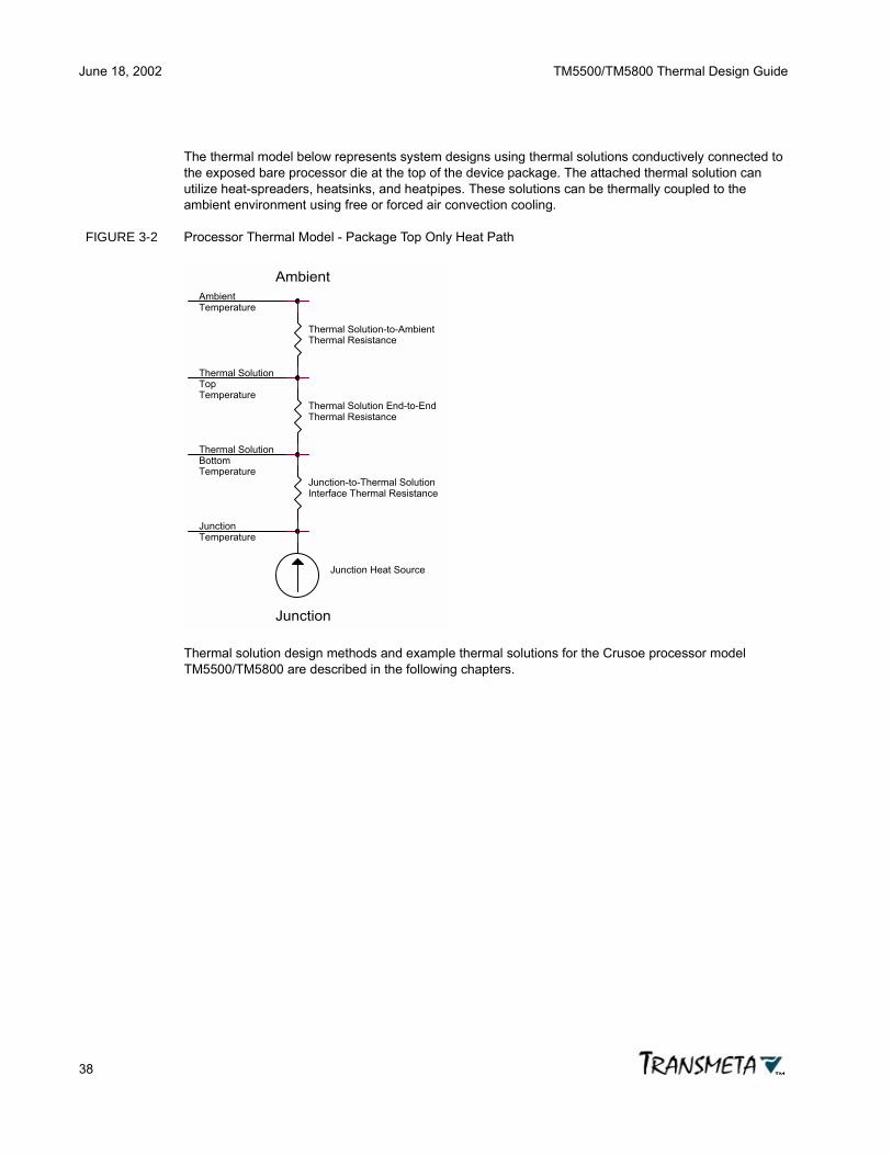
June 18, 2002 TM5500/TM5800 Thermal Design Guide
38
The thermal model below represents system designs using thermal solutions conductively connected to the exposed bare processor die at the top of the device package. The attached thermal solution can utilize heat-spreaders, heatsinks, and heatpipes. These solutions can be thermally coupled to the ambient environment using free or forced air convection cooling.
FIGURE 3-2 Processor Thermal Model - Package Top Only Heat Path
Thermal solution design methods and example thermal solutions for the Crusoe processor model TM5500/TM5800 are described in the following chapters.
Temperature
Junction
Junction
Thermal Solution-to-AmbientThermal Resistance
Top
Ambient
Temperature
Thermal Solution
Temperature
Temperature
Junction Heat Source
Bottom
Ambient
Thermal Solution End-to-EndThermal Resistance
Junction-to-Thermal SolutionInterface Thermal Resistance
Thermal Solution

TM5500/TM5800 Thermal Design Guide June 18, 2002
39
Chapter 4
Thermal Solution Design
To ensure safe operation and correct functionality of the Crusoe processor model TM5500/TM5800, the maximum specified junction temperature (Tjmax) of the processor must not be exceeded during operation at ambient temperatures up to the specified maximum temperature for the system. To design an effective thermal solution to meet this requirement, a value for the power dissipation of the processor must be known. Conventional thermal solution design dictates using the worst case power dissipation (TDPmax) for design calculations. This is a safe assumption. However, if worst case power is used, the thermal solution required may be impractical for the product.
Crusoe processor model TM5500/TM5800 with LongRun adaptive power and thermal management offers an alternative typical operating power (TDPtyp < TDPmax) value to be used in thermal solution design calculations. Though LongRun thermal management may reduce performance slightly in extremely demanding and relatively uncommon application environments, it may also allow for a reasonable thermal solution where none was previously available. The conventional thermal design methodology given below is applicable for designing with LongRun thermal management if TDPmax is replaced by TDPtyp in the calculations.
4.1 Thermal Solution Design Methodology
For typical mobile applications, the microprocessor power dissipation is a significant part of the total power dissipation of the system. Therefore, the design of the cooling solution for the processor must be integrated with the design of the cooling solution for the other components in the system. That being stated, the goal of this Thermal Design Guide is not to provide a comprehensive guide for designing system-level cooling solutions. References to a wide variety of system-level analysis tools and approaches are given in Appendix D, Thermal Engineering References.
It will be assumed here for simplicity that an approximation of the ambient conditions (temperature and air velocity) surrounding the microprocessor and board are known. Given these conditions, the board geometry, and the thermal characterization parameters (θja, θjp, θjb, TDPmax, Tjmax) for the processor, a preliminary design or sizing of the required thermal solution can be formulated. The following procedure can be used to arrive at the preliminary design:
• Obtain preliminary estimates of thermal characterization parameters and local ambient conditions from a rough system-level analysis.
• Determine if package will require a heatsink, using θja.

June 18, 2002 TM5500/TM5800 Thermal Design Guide
40
• If the package does require a heatsink, use a package-level model (see next section) in conjunction with available data or calculations for performance of heatsinks and interface materials to determine the heatsink requirements.
• Analyze the impact of the thermal solution on the system. Revise the package-level thermal design as necessary.
An example illustrating this process is given in shown below. A detailed thermal solution design example is given in Chapter 5, Thermal Solution Examples.
METHODOLOGY EXAMPLE: Consider a notebook computer system with a 667 MHz TM5500/TM5800 processor. The processor is attached to a motherboard and faces the keyboard. The components surrounding the processor on the motherboard and in the remainder of the base of the system dissipate a total of 4 W. When the processor is operating, air temperatures within the base near the processor are measured to be approximately 55°C with a worst case outside ambient temperature of 40°C. There is no fan and no air moving inside the notebook system.
• Determine whether a heatsink will be required:
Tj = Ta + (TDPmax • θja)
Ta = 55° C, TDPmax = 5.0 W, θja = 10°C/W
Therefore, Tj = 105°C > Tjmax = 100°C, and a heatsink will be required. If all of the heat is assumed to be dissipated by the heatsink, the heatsink and interface material must have a combined thermal performance of < 9°C/W.
• Calculate the effectiveness of potential thermal solutions:
• Extruded heatsink.
• Attach processor to keyboard with heatpipe.
• Thermal pad between PCB below processor and bottom of case.
• Check the impact of the thermal solutions on the other components and the design as a whole. Revise the thermal design as necessary.
• Extruded heatsink will preheat air and reduce air velocity to immediately downstream components.
• Keyboard will get hotter.
• Bottom of the case will get hotter. Add a spreader to distribute heat.
4.2 Package-Level Thermal Model
The primary thermal paths used to remove heat from the processor die for thermal management are:
• The thermal path from the exposed die surface at the device package top, through a thermal interface material to a thermal solution that transfers heat to the ambient environment.
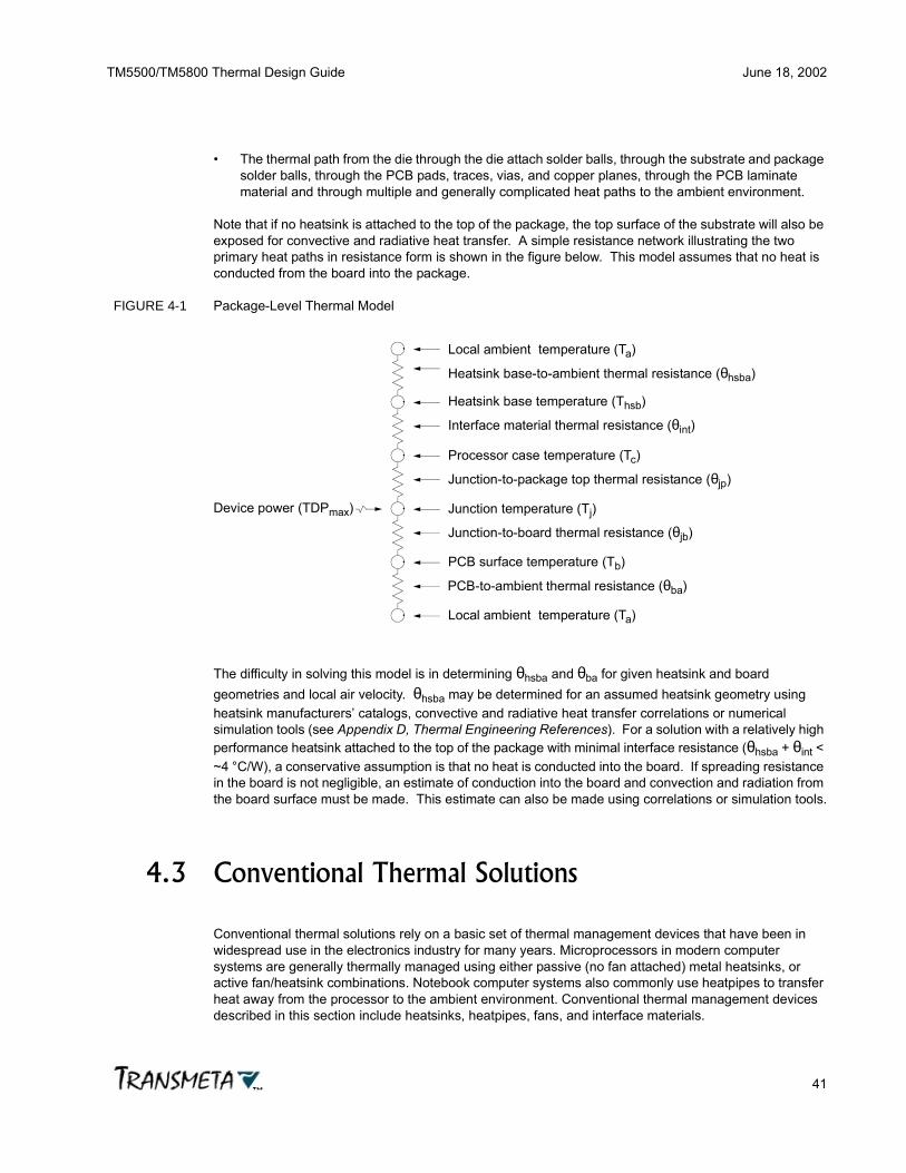
TM5500/TM5800 Thermal Design Guide June 18, 2002
41
• The thermal path from the die through the die attach solder balls, through the substrate and package solder balls, through the PCB pads, traces, vias, and copper planes, through the PCB laminate material and through multiple and generally complicated heat paths to the ambient environment.
Note that if no heatsink is attached to the top of the package, the top surface of the substrate will also be exposed for convective and radiative heat transfer. A simple resistance network illustrating the two primary heat paths in resistance form is shown in the figure below. This model assumes that no heat is conducted from the board into the package.
FIGURE 4-1 Package-Level Thermal Model
The difficulty in solving this model is in determining θhsba and θba for given heatsink and board geometries and local air velocity. θhsba may be determined for an assumed heatsink geometry using heatsink manufacturers’ catalogs, convective and radiative heat transfer correlations or numerical simulation tools (see Appendix D, Thermal Engineering References). For a solution with a relatively high performance heatsink attached to the top of the package with minimal interface resistance (θhsba + θint < ~4 °C/W), a conservative assumption is that no heat is conducted into the board. If spreading resistance in the board is not negligible, an estimate of conduction into the board and convection and radiation from the board surface must be made. This estimate can also be made using correlations or simulation tools.
4.3 Conventional Thermal Solutions
Conventional thermal solutions rely on a basic set of thermal management devices that have been in widespread use in the electronics industry for many years. Microprocessors in modern computer systems are generally thermally managed using either passive (no fan attached) metal heatsinks, or active fan/heatsink combinations. Notebook computer systems also commonly use heatpipes to transfer heat away from the processor to the ambient environment. Conventional thermal management devices described in this section include heatsinks, heatpipes, fans, and interface materials.
Local ambient temperature (Ta)
Heatsink base-to-ambient thermal resistance (θhsba)
Heatsink base temperature (Thsb)
Interface material thermal resistance (θint)
Processor case temperature (Tc)
Junction-to-package top thermal resistance (θjp)
Junction temperature (Tj)
Junction-to-board thermal resistance (θjb)
PCB surface temperature (Tb)
PCB-to-ambient thermal resistance (θba)
Local ambient temperature (Ta)
Device power (TDPmax)

June 18, 2002 TM5500/TM5800 Thermal Design Guide
42
4.3.1 Heatsinks
In the context of microprocessor-based system thermal management, a heatsink is a thermally conductive material, typically metal, used to transfer heat from the microprocessor to the ambient environment. The operating principle of a microprocessor heatsink is to thermally conduct heat from the relatively small and concentrated processor package/exposed die surface to a large surface area in contact with ambient air. By effectively increasing the surface available for convective heat transfer, the heatsink serves an intermediary role in the transfer of thermal energy from the microprocessor active junction area to ambient air. Most heatsinks used for notebook computer use are made of aluminum, and are designed to attach to the microprocessor through a compliant (soft) thermal interface material.
Typical microprocessor heatsinks have a planar area for attachment to the flat processor package, and use channels, grooves, fins, and pins on the top and sides of the heatsink to increase the surface area available for contact with ambient air. As explained in Chapter 2, Thermal Management Fundamentals, for a given heat transfer rate, the base temperature of a heatsink is inversely proportional to the surface area. By increasing the surface area available for convective heat transfer, heatsinks reduce the temperature of the surface (microprocessor package) to which they are attached.
Heatsinks are characterized by their thermal resistance (θ). As explained in Chapter 2, Thermal Management Fundamentals, thermal resistance is the temperature difference through the heatsink (from base-to-ambient) generated by the heat applied to the heatsink base. Thermal resistance is measured in °C/W. Since heatsinks transfer heat to ambient air by convection, the area of the heatsink exposed to the air and the air velocity have a dramatic influence on the heatsink effective thermal resistance. As heatsink area increases, and as air velocity increases, the effective thermal resistance of the heatsink decreases. Thus, by using heatsinks with larger surface areas exposed to moving air, the heatsink-based thermal solution can lower the microprocessor temperature quite effectively.
When selecting heatsinks for notebook microprocessor thermal management applications, consider the following factors:
• Total power dissipated by the heatsink: Choose a heatsink with a suitable thermal resistance given the power level of the microprocessor and the allowed operating temperatures of the processor, system components, and case surface. Consideration must also be made for the ambient operating environment, including air temperature, velocity, and density (altitude).
• Size, weight, and dimensional constraints: Choose a heatsink with appropriate dimensional and mass properties. Optimizing thermal performance typically leads to heatsinks that fill the available notebook computer volume. Such designs may be impractical for reasons of weight, mechanical attachment, and electrical concerns.
• Natural or forced air (fan-driven) convection: Heatsinks designed for natural convection may be shaped differently than those for forced convection to better create a chimney effect or better take advantage of radiative heat transfer. Forced convection typically requires ducts and vents that often dictate more complex mechanical assemblies.
• Direction and amount of airflow: Air movement across the heatsink substantially improves thermal performance. Heatsinks with long straight fins should be oriented parallel to the direction of airflow. Note that the heatsink creates an obstruction in the airflow path and may change the nature of the airflow surrounding it.
• Cost: Heatsinks come in a large variety of types, with widely varying costs, as described below. Natural convection thermal solutions are typically considerably less expensive than forced

TM5500/TM5800 Thermal Design Guide June 18, 2002
43
convection solutions, but do not offer the same thermal performance level (low θ) possible with fan-based solutions.
• Attachment method and effect on second level reliability: Any solution that attaches directly to the PCB and stiffens the assembly may have a detrimental effect on board-level reliability. Appropriate reliability testing should be performed prior to production.
A sampling of the large variety of heatsinks and heatsink technologies is provided below. Improvements in heatsink technology are aimed at reducing thermal resistance, both by using materials with greater thermal conductivity, and by increasing the effective surface area available for convective heat flow. Reducing cost and weight are also areas actively pursued by heatsink manufacturers. See Appendix C, Heatsinks and Fans for information on heatsink vendors.
• Cast and stamped heatsinks: These heatsinks are used for cost-sensitive applications requiring only modest cooling performance. They are generally the lowest cost heatsinks available since they are relatively inexpensive to manufacture. Heatsink fin height-to-gap ratios must be less than 6:1.
• Extruded heatsinks: These are the most common heatsinks in use today due to their low cost and good performance. Commercial extruded heatsinks are almost always made from aluminum, and are available in straight fin or pin fin configurations. Fin height-to-gap ratios in the range of 4:1 up to 10:1 are available for extruded aluminum heatsinks.
• Folded-fin heatsinks: Folded-fin heatsinks, sometimes called corrugated heatsinks, are manufactured by bending and folding thin (< 0.5 mm) metal sheets and attaching them to the heatsink metal baseplate. These heatsinks provide better performance than cast, stamped, and extruded heatsinks because they provide more surface area in a given space. They are useful in applications with limited airflow. Folded-fin heatsinks are available with fin height-to-gap ratios up to 40:1, and are typically more expensive than extruded heatsinks.
• Bonded-fin heatsinks: Similar to folded-fin heatsinks, bonded-fin heatsinks are made by gluing, soldering, or brazing thin sheet metal fins into a heatsink base that has channels cut to accept the fins. Bonded-fin heatsinks offer similar performance to folded-fin heatsinks, with fin height-to-gap ratios above 30:1 available.
• Skived-fin heatsinks: Skiving is the technology of shaving fins directly from the base metal heatsink block. This allows the entire heatsink to be constructed from a single piece of metal, eliminating the thermal resistance of the fin-to-heatsink bond required by bonded-fin heatsinks. Skiving creates lower thermal resistance connections between the fins and the metal base, and can lower heatsink manufacturing costs compared to folded-fin and bonded-fin technologies. Skived-fin heatsinks offer similar or greater thermal performance advantages as folded-fin and bonded-fin vs. extruded heatsinks. Skived-fin heatsinks are available with fin height-to-gap ratios up to 25:1.
• Fan heatsinks: Heatsinks with integral fans are commonly used for modern high-power microprocessor cooling applications. Fan heatsinks are useful in applications with cooling requirements that cannot be satisfied with natural convection, particularly where a high power dissipation heat source is confined in a small volume of space with restricted airflow. Fan heatsinks have the advantage of lower effective thermal resistance, with a corresponding improvement in thermal performance. For notebook computer applications, the inclusion of a fan can increase system cost, decrease battery life, increase system noise level, increase the likelihood of reliability (fan failure) issues, and potentially increase the weight of the system.

June 18, 2002 TM5500/TM5800 Thermal Design Guide
44
4.3.2 Heatpipes
Heatpipes are sealed metal tubes containing a small amount of fluid that are used to transfer heat from one location to another with an extremely low effective thermal resistance. Heatpipe operation is based on liquid-to-gas (vaporization) and gas-to-liquid (condensation) phase changes. The phase change occurs at a constant temperature and absorbs (vaporization) or releases (condensation) thermal energy. The fluid inside the heatpipe tube must be carefully chosen to change from liquid to gas at a temperature within the normal and safe operating range of the device being cooled. Water (under a partial vacuum) is commonly used as the working fluid in heatpipes for notebook microprocessors.
One end of the heatpipe is in close thermal contact with the microprocessor. The fluid inside this end of the heatpipe is heated until it vaporizes. The vaporized material in the heatpipe travels the length of the tube and reaches the cooler condenser end, where it condenses back into a liquid. The evaporation of the liquid removes heat from the microprocessor, and the condensation of the gas delivers the heat to the condenser end of the heatpipe. After changing back to a liquid in the condenser, the fluid travels back to the heated end of the heatpipe by the capillary action of a wicking system inside the heatpipe. Heatpipes operate in a closed loop, and will move heat from the evaporator end to the condenser end as long as an appropriate temperature difference is maintained between the two ends.
As mentioned above, heatpipes have an extremely low effective thermal resistance. The thermal resistance of a heatpipe has three components: the thermal resistance of the evaporator-end heat source-to-fluid contact, the axial thermal resistance of the heatpipe fluid, and the thermal resistance of the condenser-end heat exchanger-to-ambient air. Typical thermal resistance values for a copper-water heatpipe are 0.2 °C/W•cm2 for the end contacts and 0.02 °C/W•cm2 for the axial thermal resistance. Overall heatpipe thermal resistance is extremely low compared even to pure metals, typically in the range of 0.05-0.2 °C/W.
One factor limiting the performance of large heatsinks is the finite thermal conductivity of the heatsink material. The base temperature decreases away from the source of heat, and therefore the heat transfer rate to the ambient air reduces for the fins at the extremes. The equivalent thermal conductivity of a heatpipe is greater than 50000 W/m°K, which is more than 250 times that of aluminum. Heatpipes can be used to create a uniform temperature across the base of the heatsink in these situations. Another application of a heatpipe is when there is not enough space to install a heatsink on the component dissipating power. In this situation, a heatpipe can be used to transport the heat to another place where it can be dissipated through a heatsink.
Heatpipes are widely used in notebook computer thermal management solutions because of their light weight, ruggedness, high thermal performance, and reasonable cost. Heatpipes are available in a variety of materials, sizes, shapes, and power ratings. Heatpipes are typically custom designed for each application, with heatpipe manufacturers using design tools, manufacturing processes, and heatpipe materials they have refined over many successful product generations. See Appendix C, Heatpipes for a list of heatpipe manufacturers.
4.3.3 Fans
Fans are used to provide a guaranteed airflow velocity in forced convection thermal management solutions. By forcing moving ambient air across a heatsink, the effective thermal resistance for the heatsink is reduced, providing improved thermal performance. In notebook computer thermal management applications, small light-weight fans are frequently used to facilitate the removal of thermal energy in the compact and densely-packed interior of these systems. The rapid increase in power

TM5500/TM5800 Thermal Design Guide June 18, 2002
45
dissipation (TDPmax) of traditional notebook processors over the past several years has forced computer manufacturers to deploy more capable thermal solutions, mandating the use of ever more powerful fans and exotic heatpipe assemblies.
Although ideal notebook thermal solutions would not include fans, they may be required when the system power dissipation is greater than can be managed by natural convective methods. As notebook systems become smaller, the external case surface area decreases, and eventually the surface area available for convective heat transfer can become inadequate for system cooling requirements. A more common problem is the concentration of heat at certain ‘hot spots’ in the system, either in the interior components or at the external case surface. Alleviating heat buildup in hot spots often requires major redesign of system mechanical assemblies, and can be a major engineering challenge. The use of heatpipe/heatsink/fan assemblies can often simplify the solution of hot spot problems without having to mechanically redesign the entire system.
The following areas should be studied when considering the use of fan-based notebook thermal solutions:
• Fan-less alternatives: There are often passive (fan-free) thermal solutions that can satisfy the thermal management requirements of the system. Careful design of vents, case surface features, and internal/external natural convective airflow channels can sometimes alleviate the need for a fan-based thermal solution. The intelligent and creative use of heatpipes and heat spreaders, combined with good thermal modeling and thermo-mechanical design can often produce economical, compact, and light-weight thermal solutions without the use of fans.
• Minimize power consumption: If a fan-based thermal solution is absolutely required to meet the system thermal management requirements, consider solutions that use optimal low-power fan features. Use fans with temperature-based feedback-loop controlled fan motor operation. These solutions can minimize the battery-life impact of fan-based thermal solutions, while providing thermal performance sufficient for system cooling requirements.
• Reliability: Use only reliable long-life fans, and make sure they operate within their guaranteed safe operating specifications. Make sure over-temperature protection and thermal performance modulation (e.g. clock throttling) is provided in the system in the event of fan failure.
• Air recirculation: Carefully design the airflow path for fan-based thermal solutions. Make sure that unheated ambient air at the fan airflow input is not contaminated with preheated air from the system. This effect can seriously degrade the thermal performance of the solution.
See Appendix C, Heatsinks and Fans, for a list of fan manufacturers.
4.3.4 Interface Materials
The interface between a thermal solution and the device or assembly being cooled is extremely important for good thermal design. The contact area between a heatsink and a device package has a relatively high thermal resistance at the interface, due to the microscopic unevenness of the two mating surfaces. At the microscopic level, surface irregularities allow the two contacting surfaces to touch at only a relatively few points, with the vast majority of the void space between the surfaces filled with air. Air has a very low thermal conductivity, so the bare interface between a microprocessor package surface and a heatsink has a high thermal resistance. Thermal interface materials overcome this limitation by providing a soft, compliant, thermally conductive interface that conforms to the two surfaces and fills in the

June 18, 2002 TM5500/TM5800 Thermal Design Guide
46
microscopic air voids with low thermal resistance material. Thermal interface materials dramatically lower the thermal resistance between heatsinks and microprocessors.
WARNING THERMAL INTERFACE MATERIAL MUST BE USED BETWEEN THE TM5500/TM5800 PACKAGE AND THE ATTACHED THERMAL SOLUTION TO PREVENT DAMAGE TO THE DEVICE.
Thermal interface materials must be used between the TM5500/TM5800 package and the attached thermal solution, typically a heatsink. This is required not only for reasons of improved thermal performance, but also to protect the device package from damage. The TM5500/TM5800 FC-CBGA package has the silicon die exposed on top for attachment to the thermal solution. This silicon die is extremely brittle, and can be easily damaged by unevenly applying pressure to the exposed surface. The compliant thermal interface material buffers and redistributes the pressure applied by the thermal solution attachment mechanism, and thus protects the processor from mechanical damage.
There are a large variety of thermal interface materials available for use with the TM5500/TM5800 processor. The choice of which material to use in a specific application depends on a range of factors, including thermal performance, stability, ease of application and removal, required operating pressure, and cost, as described below.
• Thermal performance: Thermal interface materials vary widely in thermal conductivity. High thermal conductivity interface materials are preferred for notebook applications. Select a material with an appropriate level of thermal performance that meets the other interface material requirements below.
• Compliance and operating pressure: The ability of the interface material to conform to the surface features and fill air voids is very important. The ability to fill surface irregularities depends on the pressure applied to the interface material. Greater pressure forces more interface material into the surface depression air pockets, increasing thermal contact surface area, and improving thermal performance. The interface pressure must not be too high or damage to the processor package can result. Soft interface materials appropriate for notebook applications include thermal greases and compliant (low-durometer) elastomers. Thermal greases can squeeze out of the interface between the processor and heatsink over time, so care must be exercised to assure adequate thermal performance and protection of the processor die over the expected life of the system. Choose an interface material with an appropriate degree of compliance and operating pressure.
• Stability: The thermal interface material used must maintain its thermal and mechanical properties throughout the expected system life. Some interface materials age in response to operation at high temperature, pressure, or humidity over extended periods of time. Carefully investigate the physical properties of the thermal interface materials with respect to stability over the expected operating environment and lifetime of the thermal solution.
• Manufacturing process: Thermal interface materials vary widely in the manufacturing process steps required for their handling, application, and removal. Some materials, e.g. elastomers, are very easy to work with and do not require elaborate manufacturing procedures to use effectively. Thermal greases, compounds, and phase change materials require more care in handling, application, and removal. Understand fully the manufacturing requirements of the thermal interface material selected, and follow the interface material vendor recommendations for storage, handling, application, and removal.
• Size, shape, and location: The interface material size, shape, and placement on the processor and heatsink must be carefully considered. The TM5500/TM5800 exposed die must be protected from mechanical pressure damage by the interface material, so dimensioning the interface with enough material to accommodate mechanical tolerances and assembly procedure alignment errors is very important.

TM5500/TM5800 Thermal Design Guide June 18, 2002
47
The following sections describe the variety of thermal interface materials available, including thermal greases, thermal compounds, phase change materials, elastomers, and thermal adhesives, tapes, and foils. See Appendix C, Interface Materials, for a list of thermal interface material vendors.
4.3.4.1 Thermal Greases
Thermal greases are made of silicone or hydrocarbon oils with thermally conductive compounds suspended in them. Thermal greases commonly use aluminum or zinc oxide as the thermally conductive component, leading to their (usually) white appearance. Thermal greases, when squeezed between the processor package and heatsink, form a thermally conductive layer that fills the microscopic air voids between the two mating surface, resulting in a low thermal resistance interface. The hydrocarbon oil base used on some thermal greases is somewhat volatile, and may evaporate over time. Also, thermal greases have a tendency to flow under pressure, and can gradually squeeze out from the interface over time. Thermal grease does not provide adhesion between the processor and heatsink, as does some other interface materials. The thermal solution attachment mechanism must provide the mechanical pressure to hold the interface together. Care should be taken when applying thermal grease to avoid contaminating other parts of the system with the substance. Follow vendor recommendations for storage, handling, application, and removal.
4.3.4.2 Thermal Compounds
Thermal compounds are similar to thermal greases, though they usually do not have quite as good thermal performance as greases. They are high thermal conductivity materials that are designed for operation over particular temperature ranges. They are designed to partially melt during operation to flow into surface irregularities and form a semi-permanent bond between the processor package and heatsink. These materials are easier to apply than greases, and do not have the same issues with drying out over time. They also do not exhibit the same degree of pressure-induced migration over time as greases. These materials do not provide significant adhesion, and must be used with thermal solution attachment mechanisms that provide some degree of mechanical pressure.
4.3.4.3 Phase Change Materials
Phase change materials have similar properties as greases and thermal compounds. They are designed to melt and flow at typical processor operating temperatures, filling voids and minimizing the operating pressure required for good thermal interface performance. At temperatures below the normal operating point for the processor, phase change materials are pliable and plastic. They are usually pre-formed into the appropriate shape and size for the application, and pre-applied to the heatsink, making them very easy to use. Phase change materials, like greases and thermal compounds, also exhibit some degree of pressure-induced migration over time, and require thermal solution attachment mechanisms that supply a small amount of mechanical pressure. Though phase change materials are extremely easy to use, they can sometimes be difficult to remove because of certain properties of epoxy-based phase change materials that causes chemical bonds to form between the silicon die and the heatsink surface, making detachment of the heatsink from the processor extremely difficult. Avoid the use of epoxy-based phase change interface materials with the TM5500/TM5800 processor.
4.3.4.4 Elastomers
Thermal elastomers are silicone rubber pads filled with thermally conducting compounds. They have become the thermal interface material of choice for notebook computer thermal solutions because they

June 18, 2002 TM5500/TM5800 Thermal Design Guide
48
are extremely easy to use, offer excellent thermal performance, and are completely stable over the operating environment and expected life of these systems. Thermal elastomers come in pre-cut sizes and shapes, either as standard or custom products. Elastomers require somewhat higher mechanical pressure than greases, compounds, and phase change materials to force the elastomeric material into the voids in the mating surfaces. Care must be exercised when using elastomers to assure the correct amount of elastomer compression, resulting elastomer thickness, and pressure exerted on the processor package. Better thermal performance requires thinner pads, but thermal elastomers require a certain optimal compression range, and the pressure applied to the TM5500/TM5800 die surface must not exceed the limits listed in section 3.2 Mechanical Specifications. Thermal elastomers require thermal solution attachment mechanisms that have compression depth and pressure control. Also, be sure to allow enough extra elastomer material overhang to accommodate mechanical tolerances and assembly procedure alignment errors.
4.3.4.5 Thermal Adhesives, Tapes, and Foils
Thermally conductive adhesives, tapes, and foils provide adhesion as well as good thermal interface functionality. These thermal interface materials consist of glues and tapes with embedded thermally conducting compounds or metals. Although thermal tapes and foils may not have the same thermal performance as other interface materials, they provide an adhesive bond between the processor and heatsink, often eliminating the need for mechanical fasteners. Thermal adhesive can have quite high thermal conductivity, and very good adhesive properties, though they can be very difficult to remove. Thermal tapes and foils generally have much lower thermal conductivity and relatively poor adhesive properties. Thermal adhesives, tapes, and foils are not recommended for use with TM5500/TM5800 processors.
4.3.5 Thermal Solution Attachment
The means used to secure the thermal solution to the processor can be critically important for the thermal performance and reliability of the system. The attachment mechanism is used to provide consistent and controllable pressure to the thermal interface material, as well as maintaining the mechanical integrity of the heatsink-processor assembly. The rigidity of the attachment mechanism is important for protecting the processor package from mechanical damage. The thermal solution attachment system must provide all these functions without interfering with the electrical operation of the processor, reducing the thermal solution performance, or negatively affecting second level reliability of the assembly.
A variety of thermal solution attachment mechanisms are commonly used in notebook computers. These include plastic and metal screws, spacers, bosses, and springs, plastic pins, and various plastic and metal clips. The attachment mechanism is often recommended or supplied by the heatsink vendor. See Appendix C, Heatsinks and Fans for a list of heatsink vendors. Attachment mechanisms can be integrally designed into the circuit board or heatsink assembly, or attach separately. The design of thermal solution attachment mechanisms is part of the mechanical design of the notebook computer, and must be carefully considered in relation to the overall system mechanical design, as well as the thermal solution design.
The attachment system chosen should provide the correct pressure and compression of the thermal interface material, while providing enough dimensional flexibility to adjust to the expected range of processor package height and interface material thickness variations. Be aware that the TM5500/TM5800 FC-CBGA package has solder balls that may vary somewhat across a range of solder ball standoff dimensions, causing a variation from unit-to-unit in the height of the exposed die surface from

TM5500/TM5800 Thermal Design Guide June 18, 2002
49
the PCB surface. The attachment system should also provide mechanical rigidity and stability for the PCB-processor package-interface material-heatsink assembly, while not exceeding the TM5500/TM5800 maximum package pressure limit described in section 3.2 Mechanical Specifications. Consideration should also be given to the assembly and disassembly requirements of the attachment mechanism.
Care should be taken to insure that adequate clearance is provided between all thermal solution components and the capacitors mounted on the surface of the TM5500/TM5800 package.
4.4 Adaptive Thermal Solutions
Conventional thermal solutions rely on conservative thermal design techniques using maximum thermal design power (TDPmax) device specifications to assure adequate cooling is provided in the system to handle the worst-case thermal operating characteristics anticipated at design time. Since these thermal solutions are developed using worst-case thermal specifications, the resulting thermal solutions are often over-designed and highly under-utilized with respect to typical system usage profiles. These designs often include fans in anticipation of thermal conditions within the system that may only rarely occur, with the required fan airflow path layout further complicating the design. The resulting thermal solutions occupy more space, are heavier, and consume more power than necessary when compared to thermal solutions developed using newer adaptive thermal management techniques. This section of the TM5500/TM5800 Thermal Design Guide discusses two approaches to adaptive thermal management, thermal throttling, and LongRun advanced thermal management.
4.4.1 Thermal Throttling
Thermal throttling is a technique used to actively limit the operating temperature of microprocessor systems. Thermal throttling works by dynamically reducing the processors active duty cycle in response to over-temperature conditions in the system. Typically there are one or more temperature sensors integral to or attached to the processor, thermal solution, and possibly other places within the system. These temperature sensors are read periodically by the system core logic or by the system processor, and if preset temperature limits are reached or exceeded, the system will respond by actively reducing the processor active duty cycle.
The processor duty cycle is modulated by system power management logic that stops and re-starts the processor clock periodically, typically at a 4 KHz rate. By modulating the processor clock on and off, the active computational duty cycle is modulated correspondingly. Since the majority of the processor power dissipation is due to clock-driven circuit activities, the processor power dissipation is reduced in proportion to the active duty cycle reduction. Thus a processor that is 50% duty cycle throttled runs at approximately 50% of the power dissipation level compared to running unthrottled.
Using thermal throttling as an integral part of the thermal management solution for a system has several benefits. These benefits result from the relaxation of some of the worst-case thermal assumptions typically used in non-throttled thermal solutions, with a resulting smaller, lighter, and less expensive thermal solution. This is possible because instead of assuming the possibility of a worst-case application mix driving the processor to maximum power dissipation indefinitely, the temperature sensor-clock throttling feedback loop will force the processor to progressively lower active power levels as the temperature in the system rises. By moving to a closed-loop thermal control solution that responds

June 18, 2002 TM5500/TM5800 Thermal Design Guide
50
dynamically to actual system events and conditions, the processor and system temperature can be maintained within a safe thermal design envelope.
Most mobile computers today use thermal throttling to some extent as a component of the thermal management solution. Some systems still rely on conservative worst-case thermal design power thermal solutions, combined with thermal throttling as a thermal safety precaution. These systems will only rarely operate in thermally throttled mode because of the robust thermal solutions employed. Other systems use much less conservative thermal design approaches that depend heavily on thermal throttling for maintaining the system operating temperature within a safe operating region. Because the thermal solutions in these systems are not able to transfer as much heat to the ambient environment as more robust thermal solutions, the system will operate much more frequently in a thermally (and performance) throttled mode. As processor performance and power dissipation have increased over the past few years, thermal throttling has become a major factor in mobile computer system thermal management and computational performance.
The fundamental disadvantage of thermally throttled thermal management solutions is the performance penalty resulting from clock throttling. When operating at a 50% active duty cycle during thermal throttling, the processor is also effectively operating at a 50% performance level compared to running with no clock modulation. What is saved in size, weight, and cost of the throttling thermal solution is paid for by a (sometimes large) performance penalty, particularly for the latest high performance-high power mobile processors. Clock throttling thermal management solutions have increasingly been accompanied by severe performance penalties due to the conflicting trends of smaller/lighter systems and higher performance/higher power processors.
It has become exceedingly difficult to incorporate conventional high-performance mobile processors, with 10-15 Watt thermal design power (TDPmax) specifications, into popular 2-4 lb. mobile computer reduced form-factor systems without encountering severe thermally-related performance problems. Thermal throttling has become as much a performance governor (limiter) as a temperature governor in these systems, and without a better approach, these systems, though incorporating the latest high-MHz processor technology, will perform on average no better than previous generation products with much lower clock rate processors.
4.4.2 LongRun Advanced Thermal Management
Crusoe processor LongRun power management technology offers an alternative adaptive thermal management approach that provides the benefits of smaller/lighter/lower-cost thermal solutions combined with very little or no associated performance penalty. LongRun thermal management works by dynamically adapting the processor clock frequency and operating voltage, and therefore the device power dissipation, to the application performance demands and system operating temperature conditions. Instead of switching the processor clock on and off, as in conventional clock throttling, the clock frequency and operating voltage of the processor move smoothly up and down in response to system-level performance and thermal requirements. The closed-loop nature of this approach provides the same benefits as clock throttling - forcing the processor to operate within a safe operating range thermal envelope with a minimally sized thermal solution. The benefit of this approach over thermal throttling is a much lower performance penalty across the range of system activity levels and temperatures.
In LongRun advanced thermal management, the Crusoe processor temperature is constantly monitored. As the temperature rises to preset limits, LongRun power management activities will begin to reduce the operating frequency and voltage (f-V) incrementally to maintain the processor within a safe operating temperature region. If the temperature continues to rise, the processor f-V are again incrementally

TM5500/TM5800 Thermal Design Guide June 18, 2002
51
reduced. This technique will quickly stabilize without having to turn the processor clock off, thus minimizing the performance impact of this thermal control mechanism. As the processor f-V are reduced, the power dissipation in the processor decreases, and the temperature stops rising or begins to fall.

June 18, 2002 TM5500/TM5800 Thermal Design Guide
52
The figure below shows a comparison of LongRun adaptive thermal management to clock throttling thermal management, showing the performance advantage of the LongRun approach.
FIGURE 4-2 Performance Comparison - LongRun vs. Clock Throttling Thermal Management
50%
70%
10%
Power
60%
90%
80%0%
20%
40%
LongRun
50%
70%
0%
90%
30%
Clock Throttling
30%
Perfo
rman
ce
60%
100%
40%
100%10%
80%
20%

TM5500/TM5800 Thermal Design Guide June 18, 2002
53
The figure below shows the TM5500/TM5800 processor power dissipation across a range of core operating frequencies and voltages, following the LongRun power and performance optimizing algorithm. This figure clearly shows that the dynamic voltage and frequency operation of LongRun power management allows the processor to operate at much reduced power levels during most application operations, substantially reducing system power dissipation and increasing battery life.
FIGURE 4-3 Power Dissipation vs. Core Frequency-Voltage
Pow
er
Performance
800 MHz1.3 V
733 MHz1.25 V
667 MHz1.175 V
533 MHz1.025 V
600 MHz1.1 V
467 MHz0.975 V
400 MHz0.9 V
2 W
1 W
3 W
4 W
5 W
6 W
TypicalOperating
Region
PeakPerformance
Region

June 18, 2002 TM5500/TM5800 Thermal Design Guide
54

TM5500/TM5800 Thermal Design Guide June 18, 2002
55
Chapter 5
Thermal Solution Examples
5.1 Thin-and-Light Notebook Thermal Design Example
The objective of this example is to demonstrate a variety of natural convection cooling strategies for the TM5500/TM5800 processor within a typical thin-and-light notebook computer. A brief summary of the design of each cooling strategy will be presented, along with CFD (computational fluid dynamics) simulation results and a discussion of the positive and negative aspects of the design.
5.1.1 Environmental Temperature Limit Assumptions
The notebook computer must operate in a sea level 35°C room containing quiescent air. The following temperature limits apply to the notebook components and surfaces:
TABLE 5-1 Typical Temperature Limits for Notebook Computers
5.1.2 Common Simulation Assumptions
The following assumptions are common to all of the notebook designs examined:
TM5500/TM5800 processor 100°C max junction temperatureHard disk 60°C max case temperatureBattery 55°C max case temperatureGraphics chip and southbridge 85°C max case temperatureMemory - SDRAM and DDR 70°C max local ambient air temperaturePCMCIA and mini-PCI cards 70°C max local ambient air temperatureBottom skin temperature No more than 20°C above room temperaturePalm-rest temperature No more than 10°C above room temperatureKeycap temperature No more than 15°C above room temperature

June 18, 2002 TM5500/TM5800 Thermal Design Guide
56
TABLE 5-2 Notebook Computer Thermal Solution Example Assumptions
Room temperature 35°CExternal notebook base dimensions Width x Depth x Height = 250 mm x 187 mm x 20 mm.Wood tabletop Distance between bottom of notebook and wood
tabletop is 3 mm. Table is assumed to be a semi-infinite medium. Far away from the notebook, the table is at room temperature.
Processor 474-ball FC-CBGA package with exposed die.867 MHz processor dissipates 6.4 W (actual TDPmax = 6.5 W).Hypothetical processor dissipates 7.7 W
DDR SDRAM Two 66-lead TSOP-II packages near the processor. Each package dissipates 0.25 W.
Memory module One SDRAM SO-DIMM dissipates 0.5 W total.Hard disk Width x Depth x Height = 105 mm x 70 mm x 10 mm.
Dissipates 1 W.Battery Width x Depth x Height = 100 mm x 70 mm x 10.5 mm.
Dissipates no significant power.Graphics chip One 24 mm square LQFP package dissipates 1 W.Southbridge One 24 mm square LQFP package dissipates 0.5 W.PCMCIA card Width x Depth x Height = 86 mm x 55 mm x 3.3 mm
(including socket). Dissipates 1 W.Mini-PCI card (type III) Width x Depth x Height = 60mm x 45 mm x 3.3 mm
(including socket). Dissipates 0.5 W.Keyboard Width x Depth x Height = 246 mm x 102 mm x 7 mm.
Keyboard base is comprised of a layer of 0.8 mm thick aluminum surrounded by a 1 mm thick insulation layer of rubber on top and a 0.2 mm thick lamination layer of plastic underneath. Distance between keys and base = 2 mm.
Skins Skins are comprised of 1.5 mm thick plastic lined with a 0.25 mm thick aluminum sheet for EMI/ESD shielding. The 0.25 mm thick aluminum sheet extends under the keyboard but not under the palm-rest.
Magnesium spine The rear wall of the base is a 3 mm thick bar of magnesium. This structure is necessary to support the LCD screen and hinges. The screen and hinges were not included in the simulations since they are not involved in the cooling strategies analyzed.

TM5500/TM5800 Thermal Design Guide June 18, 2002
57
FIGURE 5-1 Notebook Computer Simulation - External Geometry
FIGURE 5-2 Notebook Computer Simulation - Internal Geometry
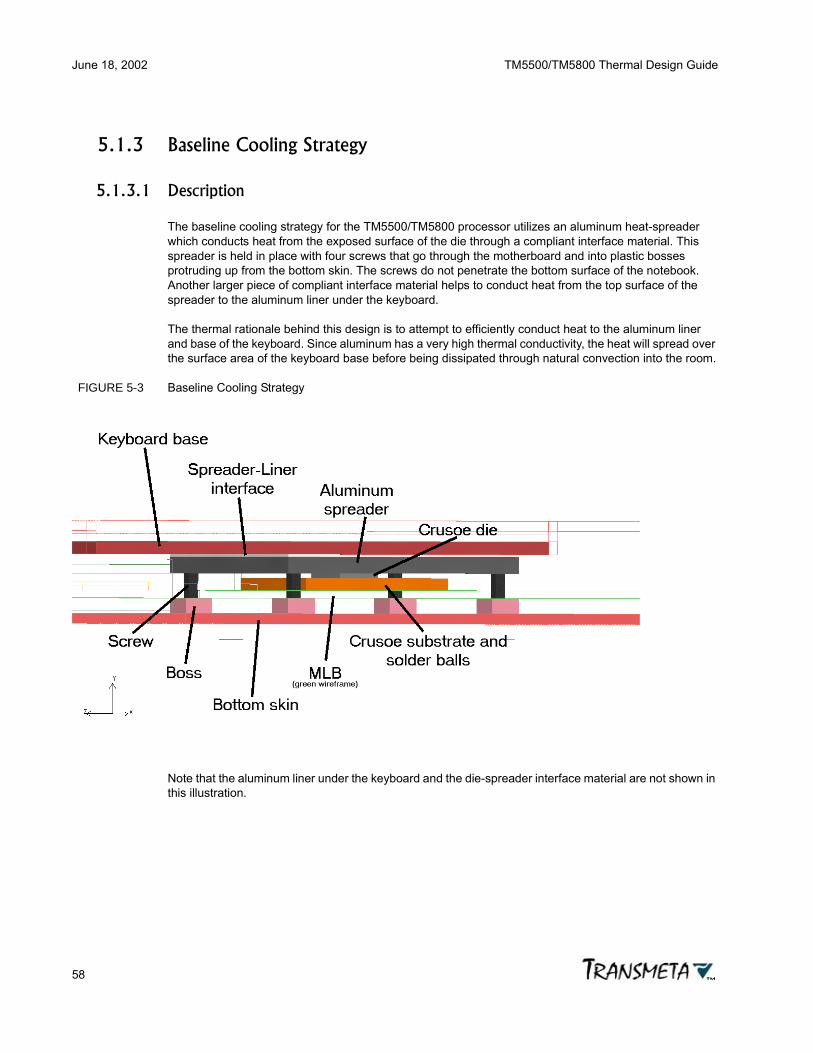
June 18, 2002 TM5500/TM5800 Thermal Design Guide
58
5.1.3 Baseline Cooling Strategy
5.1.3.1 Description
The baseline cooling strategy for the TM5500/TM5800 processor utilizes an aluminum heat-spreader which conducts heat from the exposed surface of the die through a compliant interface material. This spreader is held in place with four screws that go through the motherboard and into plastic bosses protruding up from the bottom skin. The screws do not penetrate the bottom surface of the notebook. Another larger piece of compliant interface material helps to conduct heat from the top surface of the spreader to the aluminum liner under the keyboard.
The thermal rationale behind this design is to attempt to efficiently conduct heat to the aluminum liner and base of the keyboard. Since aluminum has a very high thermal conductivity, the heat will spread over the surface area of the keyboard base before being dissipated through natural convection into the room.
FIGURE 5-3 Baseline Cooling Strategy
Note that the aluminum liner under the keyboard and the die-spreader interface material are not shown in this illustration.

TM5500/TM5800 Thermal Design Guide June 18, 2002
59
5.1.3.2 Specifics
TABLE 5-3 Example Thermal Solution Design Specifics
5.1.3.3 Results
FIGURE 5-4 Top Skin and Keycap Surface Temperatures
Keycaps are cooler than the surrounding skins due to the air gap between the keyboard base and keys.
Aluminum heat-spreader Width x Length x Height = 45 mm x 52 mm x 3.2 mm.Screws Stainless steel, 2 mm diameter, 9 mm long (including
head), torqued to create an approximately 8 psi load on the die surface.
Die-spreader interface material Covers exposed surface of die (11 mm x 8.5 mm). Thermal impedance = 0.20°C-in2/W.
Spreader-liner interface material Compressed between entire top surface of spreader (45 mm x 52 mm) and aluminum liner under keyboard. Approximately 0.5 mm thick after compression. Thermal impedance = 0.75°C-in2/W.
Processor and multilayer PCB TM5500/TM5800 867 MHz processor on a 4-layer (2-signal/2-power plane) main logic board. Power layers are 1 oz. copper.
Total power dissipated by notebook base 11.5 W.

June 18, 2002 TM5500/TM5800 Thermal Design Guide
60
FIGURE 5-5 Bottom Skin Temperatures
Note the small hot spots near the bosses. Temperatures at these locations exceed 58°C.
FIGURE 5-6 Temperatures 6 mm Above PCB
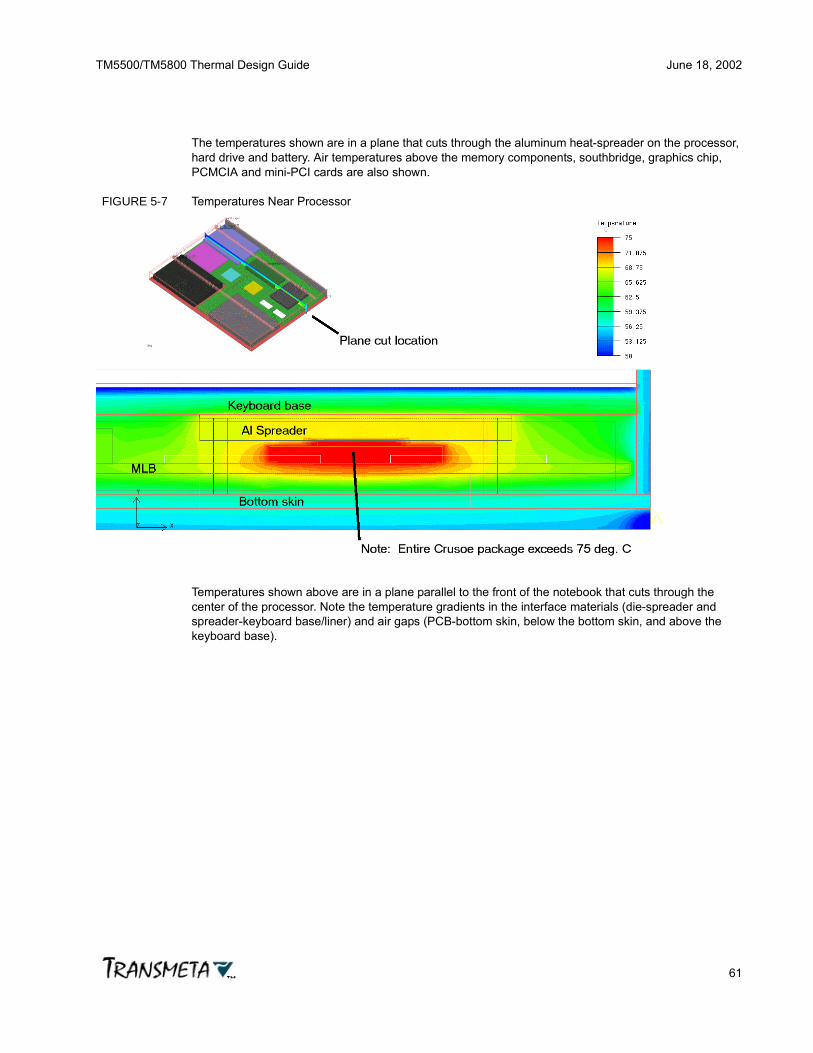
TM5500/TM5800 Thermal Design Guide June 18, 2002
61
The temperatures shown are in a plane that cuts through the aluminum heat-spreader on the processor, hard drive and battery. Air temperatures above the memory components, southbridge, graphics chip, PCMCIA and mini-PCI cards are also shown.
FIGURE 5-7 Temperatures Near Processor
Temperatures shown above are in a plane parallel to the front of the notebook that cuts through the center of the processor. Note the temperature gradients in the interface materials (die-spreader and spreader-keyboard base/liner) and air gaps (PCB-bottom skin, below the bottom skin, and above the keyboard base).

June 18, 2002 TM5500/TM5800 Thermal Design Guide
62
FIGURE 5-8 Component Surface Temperatures
Note that the memory components, add-in cards, battery, and hard drive are modeled as distributed heat sources for simplicity. This simulation does not represent temperature variations caused by the small subassemblies within these components. The top surface temperature of the heat-spreader is also shown. The processor die temperature is approximately 8°C hotter than the top surface of the heat-spreader, mainly due to the thermal resistance of the spreader-die interface material.
5.1.3.4 Concerns
All internal component temperatures are at or below their recommended maximum operating limits. However, temperatures of the palm-rest, bottom surface, and keycap surface exceed their targeted maximums. This may be acceptable for some applications. However, these skin temperature guidelines were developed with a typical consumer notebook product in mind. If the recommended maximum limits are exceeded, consumers may perceive the product to be excessively hot.
In the following sections, several strategies to reduce the maximum skin temperatures will be investigated.

TM5500/TM5800 Thermal Design Guide June 18, 2002
63
5.1.4 Variation A: Larger Heat-Spreader with Heatpipe
To enhance heat transfer from the top surface of the die to the keyboard, and to spread heat over the keyboard, an extension to the aluminum heat-spreader was added. A flattened L-shaped heatpipe was embedded into the spreader. Two more screws and bosses were added to support this extension.
By reducing the thermal resistance from the top of the die to the to surface of the notebook, die temperatures will be reduced and bottom skin temperatures will also decrease. In addition, since the heat is distributed over a larger area before it is conducted into the keyboard base, the hot spot on the top surface, above the spreader, will be elongated and its maximum temperature will be reduced.
FIGURE 5-9 Improved Heat-Spreader Geometry

June 18, 2002 TM5500/TM5800 Thermal Design Guide
64
FIGURE 5-10 Top Skin and Keycap Temperatures - Improved Heat-Spreader
FIGURE 5-11 Bottom Skin Temperatures - Improved Heat-Spreader

TM5500/TM5800 Thermal Design Guide June 18, 2002
65
FIGURE 5-12 Component Temperatures - Improved Heat-Spreader

June 18, 2002 TM5500/TM5800 Thermal Design Guide
66
5.1.5 Variation B: Increased Copper Content in Multilayer PCB
Power and ground layer thickness in the PCB was increased to 2 oz. copper. This change effectively increases the in-plane conductivity of the PCB, promoting heat to spread through the PCB, and potentially reducing hot spots on the case.
FIGURE 5-13 Temperatures Near Processor - High Conductivity PCB

TM5500/TM5800 Thermal Design Guide June 18, 2002
67
5.1.6 Variation C: Remove Bosses and Attach Heat-Spreader to PCB
Attaching the aluminum heat-spreader directly to the bottom of the case can cause hot spots on the base at the attachment points. The attachment screws conduct heat from the spreader directly to the bottom skin. It is important to minimize the temperature of the bottom skin since a user may directly contact the bottom of the unit for long periods of time.
If the heat-spreader screws are held to the multilayer PCB instead of bosses in the bottom of the case, the air gap between the PCB and the bottom of the case creates a layer of insulation with high thermal resistance. This insulation reduces the bottom skin temperature.
FIGURE 5-14 Modified Heat-Spreader Attachment Method

June 18, 2002 TM5500/TM5800 Thermal Design Guide
68
FIGURE 5-15 Bottom Case Temperatures - Modified Heat-Spreader Attachment
5.1.7 Combination of Variations A, B, and C and 7.7 W Processor
Higher frequency microprocessors dissipate more heat and therefore require more aggressive thermal solutions. To illustrate this fact, two more notebook designs were examined. The first design contained the 867 MHz TM5500/TM5800 processor, along with a combination of variations A, B, and C for the thermal solution. In the second design, the 867 MHz processor was replaced by a hypothetical 7.7 W processor.

TM5500/TM5800 Thermal Design Guide June 18, 2002
69
FIGURE 5-16 Top Skin and Keycap Temperatures - 867 MHz (Top) and 7.7 W (Bottom)

June 18, 2002 TM5500/TM5800 Thermal Design Guide
70
FIGURE 5-17 Bottom Skin Temperatures - 867 MHz (Top) and 7.7 W (Bottom)

TM5500/TM5800 Thermal Design Guide June 18, 2002
71
FIGURE 5-18 Temperatures Near Processor - 867 MHz (Top) and 7.7 W (Bottom)

June 18, 2002 TM5500/TM5800 Thermal Design Guide
72
FIGURE 5-19 Component Temperatures - 867 MHz (Top) and 7.7 W (Bottom)

TM5500/TM5800 Thermal Design Guide June 18, 2002
73
5.1.8 Summary of Component Temperatures for All Cooling Strategies
TABLE 5-4 Summary of Thermal Solution Example Simulation Results
BaselineConfig
867 MHz
VariationA
867 MHz
VariationB
867 MHz
VariationC
867 MHz
VariationsA+B+C
867 MHz
VariationsA+B+C7.7 W
Goal(Max)
°C °C °C °C °C °C ° CProcessor die 77 70 76 77 70 75 100PCB under processor
72 67 70 72 66 70
Spreader top above processor
69 62 69 70 62 66
HD surface 54-56 54-55 54-56 54-56 54-55 56-57 60Battery surface
50-52 51-53 50-52 50-52 51-53 52-55 55
Graphics package
77 76 75 75 74 77 85
Southbridge package
66 68 66 66 67 69 85
Memory module air
59-63 58-61 58-63 58-63 58-61 62-64 70
DDR SDRAM chip air
60-64 58-60 60-64 60-64 57-60 61-64 70
PCMCIA card air
54-59 56-60 54-58 54-58 56-60 57-63 70
Mini-PCI card air
53-56 56-61 53-56 53-56 56-60 57-65 70
Bottom skin 48-59 48-58 48-59 48-59 48-56 50-59 55Keyboard -top surface of base
50-62 51-58 50-62 50-62 51-58 53-61
Keyboard - keycaps
45-51 46-49 46-51 46-51 46-49 48-51 50
Top skin behind keyboard
49-62 50-58 49-61 49-61 50-57 51-60
Palm-rest 43-51 43-49 43-50 43-50 43-49 44-51 45Sidewalls 45-57 45-55 45-57 45-57 45-55 46-58

June 18, 2002 TM5500/TM5800 Thermal Design Guide
74
5.1.9 Conclusions
Based on these results, the most dramatic improvement on the baseline results was caused by variation A, increasing the size of the heat-spreader and adding a heatpipe. Variation B, increasing copper content in the multilayer PCB, did help to reduce PCB temperatures slightly, but was not a factor in reducing the skin temperatures. Variation C, attaching the heat-spreader to the motherboard instead of the bottom, eliminated the hot spots near the bosses, reducing worst case bottom surface temperatures by approximately 2°C.
Based on the table above, the most difficult areas of the notebook to bring below their recommended temperature limits were the palm-rest and bottom skin temperature. Most of the surface of the palm-rest is below its temperature limits. Only the edges are over the limit, due to the internal aluminum liner of the surrounding walls. This liner may be move back from the edges of the palm-rest if temperatures are unacceptable. The skin temperature of the bottom is more difficult to address due to the large area under the processor that may exceed its limit. The bottom skin must be thoroughly insulated from the bottom side of the PCB near the processor to reduce its temperature further. This may be accomplished by increasing the gap between the PCB and bottom skin (currently 3 mm). Adding a low conductivity (k < 0.04 W/m°K) solid material (possibly a non-conductive foam) in the gap may also help by eliminating radiative heat transfer between the two surfaces.
None of the strategies investigated had a large (>25%) improvement over the baseline. This is due to the fact that the thermal resistance of the natural convection heat transfer from the outside of the box is the main limiting factor in cooling the notebook. As more and more heat-spreaders are added, the skin temperatures approach the natural convection limit. When that limit is reached, further improvements are only possible by venting the system, adding extra surface area to the box (through the use of an external heatsink or a larger form factor) or adding a fan.
Note that the simulations presented in this document are for reference purposes only. Variability of material properties, design details, and environmental conditions can have a significant effect on the temperatures of individual components and skins. All products incorporating the Crusoe processor model TM5500/TM5800 should be thoroughly tested under worst case operating conditions to ensure compliance with thermal specifications.

TM5500/TM5800 Thermal Design Guide June 18, 2002
75
Appendix A
Thermal Terminology andNomenclature
A.1 Terminology
Adiabatic Process - a system process that takes place in such a way that no heat flows into or out of the system.
Ambient Temperature (Ta) - the temperature of the environment immediately surrounding a thermal device.
Case Temperature (Tc) - the temperature of a thermal device package, usually measured at the center of the device at the point of attachment of a thermal solution.
Conduction - a type of heat transfer that occurs when thermal energy is transmitted by direct contact between the molecules of a single object or between the molecules of two or more objects in contact with each other.
Convection - a type of heat transfer that occurs when thermal energy is transmitted from one place to another by means of fluid (either liquid or gas) motion.
Electrical Energy (Eelec) - the energy stored or transferred by the movement of charged particles, usually electrons or atom nuclei.
Energy (E) - the ability to do work. The unit of energy is the Watt-Hour or Joule. Energy is power multiplied by time, or the amount of work performed over a period of time.
Entropy (S) - a thermodynamic variable of a system that is proportional to the logarithm of the probability of the system partition corresponding to the state of the system.
Heat (Q) - the average value of the energy exchanged between a thermal device and its surroundings due to the individual exchanges of energy which occur as a result of collisions between the molecules of the thermal device and the molecules of the surroundings, when that exchange cannot be expressed macroscopically as force times displacement. Heat is the energy in transit from one body to another as a result only of a temperature difference between the two bodies.
Heat Capacity (C) - the ratio of the amount of energy (dQ) supplied to a body to its corresponding temperature rise (dT). C = dQ / dT.
PCB Temperature (Tpcb) - the temperature of the printed circuit board in the area immediately attached to a thermal device.
Power (P) - the rate at which energy is transformed, generated or consumed. The unit of power is the Watt.

June 18, 2002 TM5500/TM5800 Thermal Design Guide
76
Power Dissipation (Pdiss) - the amount of power dissipated by a thermal device. The power dissipation of a thermal device can be affected by the operating conditions and characteristics of the device temperature of the printed circuit board in the area immediately attached to a thermal device.
Radiation - a type of heat transfer that occurs when thermal energy is transmitted from one place to another by electromagnetic waves.
Specific Heat (c) - the heat capacity (C) per unit mass (m) of a body. c = dQ / m•dT.
Temperature (T) - a property of matter that is a measure of the average thermal (kinetic) energy at a specific place in an object. Common units for expressing temperature are degrees Celsius (°C), degrees Fahrenheit (°F), and degrees Kelvin (°K).
Temperature Gradient (Gt) - the change of temperature (dT) for a given change in distance (dx) within a body. GT = dT/dx
Thermal Device - any device generating and/or affected by heat in a system. In the context of this document, a thermal device is any device that converts electrical energy into thermal energy.
Thermal Energy (Etherm) - the kinetic energy of an object due to internal molecular motion. Often referred to as heat.
Thermal Equilibrium - the state where two thermally interacting objects or systems reach the same temperature.
Thermal Management - the control of the thermal operating environment and characteristics of a thermal device.
Thermal Resistance (θ) - the temperature rise of a thermal device per unit of applied thermal power. Commonly measured in degrees Celsius per Watt (°C/W).
Thermal Resistance, Junction-to-Ambient (θja) - the temperature difference between a semiconductor device junction and the ambient thermal environment per unit of power dissipated in the device junction. θja = (Tj - Ta) / P
Thermal Sink - the part of a thermal system to which heat is delivered after removal from a thermal device.
Thermal Solution - a mechanical and/or electrical device or system used to enable and/or regulate the transfer of thermal energy from one part of a system to another.
Thermal Source - the part of a thermal system from which heat is taken, usually the thermal device being cooled.
Thermodynamics - the science that studies the relationship of heat and observable macroscopic quantities such as pressure, volume, temperature, internal energy, and entropy. Thermodynamic laws include:
• Zeroth Law of Thermodynamics: There exists a scalar quantity called temperature, which is a property of all thermodynamic systems (in equilibrium states), such that temperature equality is a necessary and sufficient condition for thermal equilibrium.

TM5500/TM5800 Thermal Design Guide June 18, 2002
77
• First Law of Thermodynamics: Every thermodynamic system in an equilibrium state possesses a state variable called the internal energy U whose change dU in a differential process is given by dU = dQ - dW, where Q is the heat absorbed by the system and W is the work done by the system.
• Second Law of Thermodynamics: A transformation whose only final result is to transform into work heat extracted from a source which is at the same temperature throughout is impossible. Equivalently stated: A natural process that starts in one equilibrium state and ends in another will go in the direction that causes the entropy of the system plus environment to increase.
• Third Law of Thermodynamics: It is impossible by any procedure, no matter how idealized, to reduce any system to the absolute zero of temperature in a finite number of operations.
A.2 Nomenclature
A.2.1 Capital Letters
BGA ........................................................................................Ball Grid Array (package)
C .............................................................................................................Capacitance, F
CVDD..................................................................Crusoe processor core supply voltage
D ...............................................................................Device-specific constant, unit-less
F.............................................................View factor for radiation calculations, unit-less
FC-CBGA..................................................Flip-Chip Ceramic Ball Grid Array (package)
I ........................................................................................................Electrical current, A
L ..............................................................................................................Length, meters
P....................................................................................................... Electrical power, W
PCB................................................................................................Printed Circuit Board
Q ........................................................................... Thermal power/heat transfer rate, W
R ......................................................................... Electrical resistance, Ohms or V/Amp
T...................................................................................................Temperature, °C or °K
TDP....................................................................................... Thermal Design Power, W
V...................................................................................................... Electrical voltage, V
A.2.2 Lower-Case Letters
f ................................................................................................................Frequency, Hz
h .............................................................Heat transfer coefficient, W/m2•°K or W/m2•°C
k .....................................................................Thermal conductivity, W/m•°K or W/m•°C

June 18, 2002 TM5500/TM5800 Thermal Design Guide
78
q ....................................................................................................... Thermal flux, W/m2
A.2.3 Greek Letters
ε........................................................................................Radiative emissivity, unit-less
θ ............................................................................... Thermal resistance, °C/W or °K/W
σ ......................................................Stefan-Boltzmann constant = 5.67 x 10⁻⁸ W/m2•°K4
A.2.4 Subscripts
1-9 .........................................................................Label for surface, location, or device
a .......................................................................................................... Ambient, local air
b .....................................................................................Surface of printed circuit board
c ............................................................................................................................. Case
cond ..............................................................................................................Conductive
conv...............................................................................................................Convective
hsb ...........................................................................................................Heatsink base
j ..................................................................................... Crusoe processor chip junction
max ................................................................................................................. Maximum
min ...................................................................................................................Minimum
rad ....................................................................................................................Radiative
s ................................................................................................................ Surroundings
t ......................................................................................................................... Thermal
th ....................................................................................................................... Thermal
typ ....................................................................................................................... Typical

TM5500/TM5800 Thermal Design Guide June 18, 2002
79
Appendix B
Thermal Conversions andConstants
B.1 Thermal Conversion Factors
TABLE B-1 Thermal Conversion Factors
ConversionsAcceleration 1 m/sec2 = 4.2520 x 107 ft/hr2
Area 1 mm2 = 0.01 cm2 10-6 m2
1 mm2 = 1.5500 x 10⁻³ in2
1 cm2 = 100 mm2 10-4 m2
1 cm2 = 0.15500 in2 1.076 x 10⁻³ ft2
1 m2 = 106 mm2 104 cm2
1 m2 = 1550.0 in2 10.764 ft2
1 mil2 = 6.4516 x 10⁻⁴ mm1 mil2 = 10-6 in2
1 in2 = 645.2 mm2 6.452 cm2 6.452 x 10⁻⁴
m2
1 in2 = 6.9444 x 10⁻³ ft2
1 ft2 = 9.290 x 104 mm2 929.0 cm2 9.290 x 10⁻²
m2
1 ft2 = 144 in2
Energy 1 J = 9.4787 x 10⁻⁴ BtuForce 1 N = 0.22481 lbfHeat transfer rate 1 W = 3.4123 Btu/hrHeat flux 1 W/m2 = 0.3171 Btu/(hr•ft2)Heat generation rate
1 W/m3 = 0.09665 Btu/(hr•ft3)
Heat transfer coeff. 1 W/(m2 • °K) = 0.17612 Btu/(hr•ft2•°F)
Kinematic viscosity 1 m2/sec = 3.875 x 104 ft2/hrLatent heat 1 J/kg = 4.2995 x 10⁻⁴ Btu/lbmLength 1 m = 10-3 mm 10-4 cm 10-6 m
1 m = 0.03937 mil

June 18, 2002 TM5500/TM5800 Thermal Design Guide
80
1 mm = 39.37 mil 0.03937 in 0.0032808 ft1 cm = 393.7 mil 0.3937 in 0.032808 ft1 m = 3.9370 x 10⁴ mil 39.370 in 3.2808 ft1 mil = 2.540 x 10⁻² mm 2.540 x 10⁻³ cm 2.540 x 10⁻⁵ m1 mil = 10-3 in 8.3333 x 10⁻⁴ ft1 in = 25.40 mm 2.540 cm 0.02540 m1 in = 103 mil 0.08333 ft1 ft = 304.8 mm 30.48 cm 0.3048 m1 ft = 1.2 x 10⁴ mil 12.0 in
Mass 1 kg = 2.2046 lbmMass density 1 kg/m3 = 0.062428 lbm/ft3
Mass flow rate 1 kg/sec = 7936.6 lbm/hrMass transfer coeff.
1 m/sec = 1.1811 x 104 ft/hr
Pressure and stress
1 N/m2 = 0.020886 lbf/ft2 1.4505 x 10⁻⁴ lbf/in2
1 atmosphere =
1.01325 x 10⁵ N/m2
1 bar = 105 N/m2
Specific heat 1 J/(kg • °K) = 2.3886 x 10⁻⁴ Btu/(lbm•°F)
Temperature Kelvin, °K = °C + 273.15 (5/9)(°F + 459.67) (5/9)°RCelsius, °C = °K - 273.15 5/9(°F - 32)Fahrenheit, °F =
(9/5)°K - 459.67 (9/5)°C + 32
Rankine, °R = (9/5)°KTemp. difference 1 °K = 1 °C (9/5)°F (9/5)°R
1° R = 1 °F (5/9)°K (5/9)°CThermal conductivity
1 W/(m • °K) = 0.57782 Btu/(hr•ft•°F)
Thermal resistance 1 °K/W = 0.52750 °F/(hr•Btu)Viscosity 1 (N • sec)/m2
=2419.1 lbm/(ft•hr)
Volume 1 mm3 = 10-3 cm3 10-9 m3
1 mm3 = 6.1023 x 10⁻⁵ in 3.5314 x 10⁻⁸ ft3
1 cm3 = 103 mm3 10-6 m3
1 cm3 = 6.1023 x 10⁻² in3 3.5314 x 10⁻⁵ ft3
1 m3 = 109 mm3 106 cm3
1 m3 = 6.1023 x 10⁴ in3 35.314 ft3 264.17 gal
1 in3 = 16.39 cm3 1.639 x 10⁻⁵ m3
Conversions

TM5500/TM5800 Thermal Design Guide June 18, 2002
81
B.2 Thermal Constants
TABLE B-2 Thermal Constants
1 in3 = 5.787 x 10⁻⁴ ft3
1 ft3 = 2.832 x 104 cm3 2.832 x 10⁻² m3
1 ft3 = 1728. in3
Volume flow rate 1 m3/sec = 1.2713 x 105 ft3/hr 2.1189 x 103 ft3/min
1 m3/sec = 1.5850 x 10⁴ gal/min
ConstantsAtmospheric pressure (normal), p = 101,325 N/m2
Avagadro’s number, N = 6.024 x 10²³ molecules/molBoltzmann’s constant, k = 1.380 x 10⁻²³ Joules/°K 8.625 x 10⁻⁵ electron volt/°KGravitational acceleration at sea level, g =
9.807 m/sec2
Stefan-Boltzmann constant, s = 3.65 x 10⁻¹¹ Watts/(in2 • °K4) 5.670 x 10⁻⁸ Watts/(m2 • °K4)
Conversions

June 18, 2002 TM5500/TM5800 Thermal Design Guide
82

TM5500/TM5800 Thermal Design Guide June 18, 2002
83
Appendix C
Thermal Product Vendors
C.1 Interface Materials
Electronics Cooling MagazineIndex of interface materials vendors:http://www.electronics-cooling.com/html/body_interface_materials.htmlIndex of adhesives vendors:http://www.electronics-cooling.com/html/body_adhesives.html
The Berquist CompanyMinneapolis, MN, USA612.820.6512 (USA)800.347.4572 (USA-toll free)http://www.berquistcompany.com
Chomerics, Division of Parker Hannifin Corp.Woburn, MA, USA781.935.4850 (USA)http://www.chomerics.com
Shin-Etsu MicroSi, Inc.Phoenix, AZ, USA602.893.8898 (USA)888.642.7674 (USA-toll free)http://www.microsi.com
Thermagon, Inc.Cleveland, OH, USA216.741.7659 (USA)888.246.9050 (USA-toll free)http://www.thermagon.com
C.2 Heatsinks and Fans

June 18, 2002 TM5500/TM5800 Thermal Design Guide
84
Electronics Cooling MagazineIndex of heatsinks and extrusions vendors:http://www.electronics-cooling.com/html/body_heat_sinks.htmlIndex of fan vendors:http://www.electronics-cooling.com/html/body_fans.html
AavidLaconia, NH, USA603.224.1117 (USA)603.528.3400 (USA)http://www.aavid.com
Aavid ThermalloyConcord, NH, USA603.528.3400 (USA)81.3.53.66.84.01 (Japan)886.2.2793.5677 (Taiwan)http://www.aavid.com
Cooler MasterFremont, CA, USA510.770.0149 (USA)http://www.coolermaster.com
Intricast, Inc.Santa Clara, CA, USA408.988.6200 (USA)http://www.intricast.com
Sanyo Denki Co., Ltd.Tokyo, Japan81.3.3917.2223 (Japan)http://www.sanyodenki.co.jp
Sunon Inc.Brea, CA, USA714.255.0208 (USA)http://www.sunon.com
SunonwealthTaiwan886.7.716.3069 (Taiwan)http://www.sunon.com.tw
Thermalloy, Inc.Dallas, TX, USA972.243.4321 (USA)http://www.thermalloy.com

TM5500/TM5800 Thermal Design Guide June 18, 2002
85
Wakefield Engineering, Inc.Wakefield, MA, USA617.245.5900 (USA)http://www.wakefield.com
C.3 Heatpipes
Electronics Cooling MagazineIndex of heatpipe vendors:http://www.electronics-cooling.com/html/body_heat_pipes.html
EnertronMesa, AZ, USA602.649.5400 (USA)http://www.enertron-inc.com
Furakawa Electric North AmericaPeachtree City, GA, USA770.487.1234 (USA)http://www.furakawa-usa.com
Indek CorporationSanta Clara, CA, USA408.752.8980 (USA)http://www.indek.com
Thermacore International Inc.Lancaster, PA, USA717.569.6551 (USA)http://www.thermacore.com
C.4 Thermal Measurement Instrumentation
Kurz Instruments, Inc.Monterey, CA, USA831.646.5911 (USA)800.424.7356 (USA-toll free)http://www.kurz-instruments.com

June 18, 2002 TM5500/TM5800 Thermal Design Guide
86
National Instruments, Inc.Austin, TX, USA512.794.0100 (USA)http://www.ni.com
Omega Engineering, Inc.Stamford, CT, USA203.359.1660 (USA)800.622.2378 (USA-toll free)http://www.omega.com
C.5 Thermal Design Services and Software
Electronics Cooling MagazineIndex of thermal engineering consultants:http://www.electronics-cooling.com/html/consultants.html
Applied Thermal Technologies, Inc.Santa Clara, CA, USA408.522.8730 (USA)http://www.thermalcooling.com
Electronic Cooling Solutions IncorporatedSunnyvale, CA, USA408.749.8661 (USA)http://www.ecooling.com
Flomerics (Flotherm software)508.460.0112 (USA)http://www.flomerics.com
Fluent Inc.(icepak software)Lebanon, NH, USA603.643.2600 (USA)800.445.4454 (USA-toll free)http://www.fluent.comhttp://www.icepak.com

TM5500/TM5800 Thermal Design Guide June 18, 2002
87
Appendix D
Thermal EngineeringReferences
D.1 Fundamentals of Heat Transfer
D.1.1 Conductive, Convective, and Radiative Heat Transfer
Fundamentals of Heat and Mass Transfer, 4th EditionFrank Incropera, David DeWittJohn Wiley & Sons, 1996ISBN 0-471-30460-3http://www.wiley.com
Heat Transfer, 8th EditionJ.P. HolmanMcGraw-Hill, 1997ISBN 0-07-844785-2http://www.ee.mcgraw-hill.com
D.1.2 Convective Heat Transfer
Convective Heat and Mass TransferWilliam Kays, Michael CrawfordMcGraw-Hill, 1993ISBN 0-07-033721-7http://www.ee.mcgraw-hill.com
D.1.3 Radiative Heat Transfer
Radiative Heat TransferMichael Modest
Thermal Radiation Heat TransferRobert Siegel, John HowellHemisphere, 1992ISBN 0-891-16271-2
June 18, 2002 TM5500/TM5800 Thermal Design Guide
88
D.1.4 Thermodynamics
Fundamentals of Engineering ThermodynamicsMichael Moran, Howard ShapiroJohn Wiley & Sons, 1998ISBN 0-471-31713-6http://www.wiley.com
Engineering Thermodynamics, 2nd EditionWilliam Reynolds, Henry PerkinsMcGraw-Hill, 1977ISBN 0-07-052046-1http://www.ee.mcgraw-hill.com
D.2 Thermal Measurement and Characterization Standards
D.2.1 IEEE
MIL-STD 883C Method 1012.1 Thermal Characteristics (for determination of microelectronic device junction temperature, package thermal resistance, case and mounting temperature, and thermal response time)
IEEE - Institute of Electrical and Electronics EngineersNew York, NY, USA212.705.7999 (USA)http://www.ieee.org
D.2.2 JEDEC
Methodology for the Thermal Measurement of Component Packages (single semiconductor device), JESD51
Integrated Circuit Thermal Measurement Method - Electrical Test Method (single semiconductor device), JESD51-1
Integrated Circuits Thermal Test Method Environmental Conditions Natural Convection (still air), JESD51-2
Low Effective Thermal Conductivity Test Board for Leaded Surface Mount Packages, JESD51-3
Thermal Test Chip Guidelines (wire-bond chips), JESD51-4
JESD51-5 through JESD51-8JEDEC - Joint Electron Device Engineering CouncilEIA - Electronic Industry Association (JEDEC is a part of EIA)

TM5500/TM5800 Thermal Design Guide June 18, 2002
89
Arlington, VA, USA703.907.7560 (USA)http://www.eia.orghttp://www.jedic.org
D.2.3 SEMI
Test Method for Junction-to-Case Thermal Resistance Measurements of Ceramic Packages, G30-88
Test Method for Thermal Transient Testing for Die, G46-88
Test Method for Junction-to-Case Thermal Resistance Measurements of Molded Plastic Packages, G43-87
Specification for Thermal Test Board Standardization for Measuring Junction-to-Ambient Thermal Resistance of Semiconductor Packages, G42-87
Test Method for Still- and Forced-Air Junction-to-Ambient Thermal Resistance Measurements of Integrated Circuit Packages, G38-0996
SEMI - Semiconductor Equipment and Materials InternationalNorth America (Headquarters)Mountain View, CA, USA415.964.5111 (USA)http://www.semi.org
D.3 Printed Circuit Board Thermal Characteristics - IPC
Qualification and Performance Specifications for Rigid Printed Boards, IPC-RB-276
Performance Specifications for Rigid Flex Printed Boards, IPC-RF-245
Thermal Characteristics of Multilayer Interconnection Boards, IPC-TR-470
Generic Performance Specification for Printed Boards, IPC-6011
IPC - Institute for Interconnection and PackagingNorthbrook, IL, USA847.509.9700 (USA)http://www.ipc.org
D.4 Other Thermal Engineering References
Electronics Cooling Magazinehttp://www.electronics-cooling.com

June 18, 2002 TM5500/TM5800 Thermal Design Guide
90
Articles published in Electronics Cooling Magazine:http://www.electronics-cooling.com/html/articles.html
Air Cooling Technology for Electronic EquipmentSung Jin Kim, Sang Woo LeeCRC Press, 1996ISBN 0-8493-9447-3
Thermal Design and OptimizationAdrian Bejan, George Tsatsaronis, Michael MoranJohn Wiley & Sons, 1996ISBN 0-471-58467-3http://www.wiley.com
Thermal Management HandbookJerry Sergent, Al KrumMcGraw-Hill, 1998ISBN 0-07-026699-9http://www.ee.mcgraw-hill.com
National Electronics Cooling Course and WorkshopCourse notes by Dr. Vivek Mansingh

TM5500/TM5800 Thermal Design Guide June 18, 2002
91
Appendix E
Package Drawings


June 18, 2002 TM5500/TM5800 Thermal Design Guide
94