Embed Size (px)
Citation preview

TM
602080
REVISED DATE: JAN. 2007

SAFETY
(NOTES, CAUTIONS AND WARNINGS CONTINUED ON INSIDE OF BACK COVER)
NOTES, CAUTIONS AND WARNINGS
Throughout this guide NOTE, CAUTION and WARNINGwill be used.
A NOTE indicates a condition that should beobserved.
A CAUTION indicates a condition thatmay result in damage to the vehicle.
A WARNING indicates ahazardous condition thatcould result in severe
injury or death.
Observe these NOTES, CAUTIONS and WARNINGS;be aware that servicing a vehicle requires mechanicalskill and a regard for conditions that could be hazardous.Improper service or repair may damage the vehicle orrender it unsafe.
Engine exhaust from thisproduct contains chemi-cals known, in certain
quantities, to cause cancer, birth defects, or otherreproductive harm.
The exhaust emissions of this vehicles’ enginecomplies with regulations set forth by the Envi-
ronmental Protection Agency (EPA) of the United States ofAmerica (USA) at time of manufacture. Significant fines couldresult from modifications or tampering with the engine, fuel,ignition or air intake systems.
Battery posts, terminalsand related accessoriescontain lead and lead
compounds. Wash hands after handling.
This spark ignition system meets all require-ments of the Canadian Interference-Causing
Equipment Regulations.
Read and understand the following warningsbefore attempting to operate the vehicle:
To prevent personalinjury or death, observethe following:
When vehicle is to be left unattended, engage parkingbrake, move direction selector to ‘F’ (forward)position, turn key to ‘OFF’ position and remove key.
Drive vehicle only as fast as terrain and safetyconsiderations allow. Consider the terrain and trafficconditions. Consider environmental factors whicheffect the terrain and the ability to control the vehicle.
Avoid driving fast down hill. Sudden stops or changeof direction may result in a loss of control. Use servicebrake to control speed when traveling down an incline.
Use extra care and reduced speed when driving onpoor surfaces, such as loose dirt, wet grass, gravel,etc.
All travel should be directly up or down hills.
Use extra care when driving the vehicle across anincline.
Stay in designated areas and avoid steep slopes. Usethe parking brake whenever the vehicle is parked.
Keep feet, legs, hands and arms inside vehicle at alltimes.
Avoid extremely rough terrain.
! !
! !
! !
Ce système d'allumage par étincelle de véhicule respectetoutes les exigences du Règlement sur le matériel brouilleurdu Canada.
! !
For any questions on material contained in this manual, contact an authorized representative for clarification.
Read and understand all labels located on the vehicle. Always replace any damaged or missing labels. See APPENDIXA.
On steep hills it is possible for vehicles to coast at greater than normal speeds encountered on a flat surface. To pre-vent loss of vehicle control and possible serious injury, speeds should be limited to no more than the maximum speedon level ground. See GENERAL SPECIFICATIONS. Limit speed by applying the service brake.
Catastrophic damage to the drive train components due to excessive speed may result from driving the vehicle abovespecified speed. Damage caused by excessive speed may cause a loss of vehicle control, is costly, is consideredabuse and will not be covered under warranty.
Be sure that this manual remains as part of the permanent service record should the vehicle be sold.
For towing/transporting vehicle, refer to “TRANSPORTING VEHICLE”.

E-Z-GO Division of TEXTRON, Inc. reserves thmation contained in this manual is subject to ch
E-Z-GO Division of TEXTRON, Inc. is not liablemanual.
TO CONTACT US
NORTH AMERICA:
TECHNICAL ASSISTANCE & WA
SERVICE PARTS PHONE: 1-88
INTERNATIONAL:
PHONE: 010-1-706-798-4311, FA
E-Z-GO DIVISION OF TEXTRO
OWNER’S MANUAL
AND SERVICE GUIDE
GASOLINE POWERED
UTILITY VEHICLE
ST 4x4
STARTING MODEL YEAR 2005
Page iOwner’s Manual and Service Guide
e right to make design changes without obligation to make these changes on units previously sold and the infor-ange without notice.
for errors in this manual or for incidental or consequential damages that result from the use of the material in this
RRANTY PHONE: 1-800-774-3946, FAX: 1-800-448-8124
8-GET-EZGO (1-888-438-3946), FAX: 1-800-752-6175
X: 010-1-706-771-4609
N, INC., 1451 MARVIN GRIFFIN ROAD, AUGUSTA, GEORGIA USA 30906-3852

GENERAL INFORMATION
This vehicle has been designed and manufactured in the United States of America (USA) as
a ‘World Vehicle’. The Standards and Specifications listed in the following text originate in
the USA unless otherwise indicated.
The use of non Original Equipment Manufacturer (OEM) approved parts may void the
warranty.
Overfilling battery may void the warranty.
Tampering with or adjusting the governor to permit vehicle to operate at above factory
specifications will void the vehicle warranty.
When servicing engines, all adjustments and replacement components must be per original
vehicle specifications in order to maintain the United States of America Federal and State
emission certification applicable at the time of manufacture.
BATTERY PROLONGED STORAGE
All batteries will self discharge over time. The rate of self discharge varies depending on the
ambient temperature and the age and condition of the batteries.
A fully charged battery will not freeze in winter temperatures unless the temperature falls
below -75° F (-60° C).
Page ii Owner’s Manual and Service Guide

Page iii
TABLE OF CONTENTS
Owner’s Manual and Service Guide
SAFETY ................................................................................................................ inside covers
GENERAL INFORMATION ....................................................................................................... ii
SAFETY INFORMATION ......................................................................................................... vii
WELCOME ................................................................................................................................. 1
BEFORE INITIAL USE .............................................................................................................. 1Fig.1 Initial Service Chart ...........................................................................................................1
CAPABILITIES .......................................................................................................................... 1TERRAIN .............................................................................................................................................................1VEHICLE CAPACITY ..........................................................................................................................................1MODIFICATIONS TO VEHICLE ..........................................................................................................................2
COMMON SENSE OPERATION ............................................................................................... 2
RUN-IN ....................................................................................................................................... 2
CONTROLS & INDICATORS .................................................................................................... 3SERVICE BRAKE PEDAL ...................................................................................................................................3
Fig. 2 Service Brake Pedal ........................................................................................................3Fig. 3 Park Brake and Indicator .................................................................................................3
CHOKE ................................................................................................................................................................3Fig. 4 Choke ..............................................................................................................................4
IGNITION SWITCH ..............................................................................................................................................3Fig. 5 Ignition Switch ..................................................................................................................4
DIRECTION SELECTOR .....................................................................................................................................4Fig. 6 Direction Selector and Differential Locks .........................................................................4
2WD/4WD SELECTOR ....................................................................................................................................... 5Fig. 7 2WD/4WD Selector ..........................................................................................................5
DIFFERENTIAL LOCK ........................................................................................................................................5Fig. 8 Differential Lock ...............................................................................................................5
ACCELERATOR ..................................................................................................................................................6Fig. 9 Accelerator Pedal ............................................................................................................6
FUEL .......................................................................................................................................... 6FUEL GAUGE ......................................................................................................................................................6
Fig. 10 Fuel Tank and Gauge ....................................................................................................7LOW OIL PRESSURE INDICATOR LIGHT .........................................................................................................6
Fig. 11 Low Pressure Oil Light ...................................................................................................7LIGHT SWITCHES ..............................................................................................................................................7
Fig. 12 Light Switches ................................................................................................................712 VOLT POWER OUTLET .................................................................................................................................7
Fig. 13 Power Outlet ..................................................................................................................7
STARTING AND DRIVING ........................................................................................................ 8STARTING VEHICLE ON A HILL ........................................................................................................................8COASTING ..........................................................................................................................................................8
LOAD BED ................................................................................................................................. 8TAILGATE ...........................................................................................................................................................9MANUAL LIFT BED .............................................................................................................................................9
Fig. 14 Manual Lift Bed Release ................................................................................................9ELECTRIC LIFT BED OPERATION ....................................................................................................................9
Fig. 15 Electric Lift Bed Switch ..................................................................................................9
WINCH ....................................................................................................................................... 9WINCH APPLICATIONS .....................................................................................................................................9
Fig. 16 Do Not Pull at Angle ....................................................................................................10WINCH MOUNTING ..........................................................................................................................................10
Fig. 17 Mounting Winch ...........................................................................................................11WINCH OPERATION ........................................................................................................................................10
Fig. 18 Use Nylon Sling and Install a Damper when Winching ................................................11Fig. 19 Winch Operation ..........................................................................................................12

Page iv Owner’s Manual and Service Guide
TABLE OF CONTENTS
TOP AND WINDSHIELD ..........................................................................................................12
TRANSPORTING VEHICLE ....................................................................................................12TOWING ........................................................................................................................................................... 12
HAULING .................................................................................................................................12
TOWING A TRAILER ...............................................................................................................12
OPENING THE COWL (HOOD) ...............................................................................................13Fig. 20 Unlatching Cowl .......................................................................................................... 13
DATA LABEL LOCATION .......................................................................................................13
MAINTENANCE .......................................................................................................................14
PERIODIC SERVICE SCHEDULE ...........................................................................................15Fig. 21 Periodic Service Schedule .......................................................................................... 15
BASIC SERVICE PARTS .........................................................................................................16Fig. 22 Basic Service Parts ..................................................................................................... 16
LIFTING THE VEHICLE ...........................................................................................................17Fig. 23 Lifting the Vehicle ........................................................................................................ 17
OIL ............................................................................................................................................17Fig. 24 Recommended Oil ...................................................................................................... 17
OIL LEVEL CHECK .......................................................................................................................................... 18Fig. 25 Oil Fill and Level Check .............................................................................................. 18
OIL CHANGE .................................................................................................................................................... 18Fig. 26 Oil Change .................................................................................................................. 18
OIL FILTER CHANGE ...................................................................................................................................... 18Fig. 27 Oil Filter Change ......................................................................................................... 19
SPARK PLUGS ........................................................................................................................19
ALTERNATOR BELT ...............................................................................................................19ADJUSTING BELT ............................................................................................................................................ 19
Fig. 28 Adjusting Alternator Belt .............................................................................................. 20
AIR CLEANER .........................................................................................................................20CANISTER TYPE AIR CLEANER .................................................................................................................... 20CLEANING AIR FILTER ELEMENT ................................................................................................................. 20
Fig. 29 Air Cleaner .................................................................................................................. 20
FUEL FILTER ...........................................................................................................................20Fig. 30 Fuel Filter .................................................................................................................... 21
LUBRICATION POINTS ...........................................................................................................21Fig. 31 Lubrication Points ........................................................................................................ 21
BATTERY .................................................................................................................................21BATTERY CLEANING ...................................................................................................................................... 22
Fig. 32 Cleaning Battery .......................................................................................................... 22
JUMP STARTING ....................................................................................................................22Fig. 33 Jump Starting .............................................................................................................. 23
VEHICLE CLEANING AND CARE ..........................................................................................22CLEANING ........................................................................................................................................................ 22CARE PRODUCTS ........................................................................................................................................... 23
LABELS AND PICTOGRAMS .................................................................................................23
WHEELS AND TIRES ..............................................................................................................24TIRE INSPECTION AND INFLATION .............................................................................................................. 24REMOVAL AND INSTALLATION ..................................................................................................................... 24
Fig. 34 Wheel Tightening Sequence ....................................................................................... 24

Page v
TABLE OF CONTENTS
Owner’s Manual and Service Guide
LIGHT BULB REPLACEMENT ............................................................................................... 25Fig. 35 Headlight Replacement ...............................................................................................25
FUSE REPLACEMENT ........................................................................................................... 25
SPARK ARRESTER ................................................................................................................ 25Fig. 36 Cleaning Spark Arrester ..............................................................................................25
PROLONGED STORAGE ....................................................................................................... 25
FRONT AND REAR AXLES .................................................................................................... 26CHECKING LUBRICANT LEVEL ......................................................................................................................26
Fig. 37 Checking Axle Lubricant ..............................................................................................26
TRANSFER CASE ................................................................................................................... 26CHECKING LUBRICANT LEVEL ......................................................................................................................26
Fig. 38 Checking Transfer Case Lubricant ..............................................................................26
AIR INTAKE AND COOLING FINS ........................................................................................ 26Fig. 39 Cleaning Air Intake and Cooling Fins ..........................................................................27
BRAKES .................................................................................................................................. 27PERIODIC BRAKE TEST FOR HYDRAULIC BRAKES ....................................................................................27
CAPACITIES ............................................................................................................................ 27Fig. 40 Capacities ....................................................................................................................27
HARDWARE ............................................................................................................................ 28Fig. 41 Torque Specifications and Bolt Grades .......................................................................28
GENERAL SPECIFICATIONS.................................................................................................. 29Fig. 42 Vehicle Dimensions ......................................................................................................31Fig. 43 Vehicle Incline Specifications .......................................................................................31Fig. 44 Vehicle Turning Clearance Diameter and Intersecting Aisle Clearance .......................32
VEHICLE WARRANTIES ......................................................................................................... 33
EMISSION CONTROL SYSTEM WARRANTY STATEMENT ................................................. 35
ENGINE OWNER WARRANTY POLICY ................................................................................. 35
INTERNATIONAL WARRANTY STATEMENT ........................................................................ 35
DECLARATION OF CONFORMITY (EUROPE ONLY)............................................................ 37
LABELS AND PICTOGRAMS.............................................................................................. A - 1Fig. 45 Label Locations......................................................................................... Appendix A - 3Fig. 46 Pictogram Definitions................................................................................ Appendix A - 4Fig. 47 Pictogram Definitions................................................................................ Appendix A - 5Fig. 48 Pictogram Definitions................................................................................ Appendix A - 6Fig. 49 Pictogram Definitions................................................................................ Appendix A - 7

Page vi Owner’s Manual and Service Guide
TABLE OF CONTENTS
Notes:

SAFETY INFORMATION
This manual has been designed to assist in maintaining the vehicle in accordance with procedures developed by themanufacturer. Adherence to these procedures and troubleshooting tips will ensure the best possible service from theproduct. To reduce the chance of personal injury or property damage, the following must be carefully observed:
GENERAL
Many vehicles are used for a variety of tasks beyond the original intended use of the vehicle; therefore, it is impossibleto anticipate and warn against every possible combination of circumstances that may occur. No warnings can take theplace of good common sense and prudent driving practices.
Good common sense and prudent driving practices do more to prevent accidents and injury than all of the warningsand instructions combined. The manufacturer strongly suggests that all users and maintenance personnel read thisentire manual paying particular attention to the CAUTIONS and WARNINGS contained therein.
If you have any questions regarding this vehicle, contact your closest representative or write to the address on theback cover of this publication, Attention: Product Service Department.
The manufacturer reserves the right to make design changes without obligation to make these changes on units previ-ously sold and the information contained in this manual is subject to change without notice.
The manufacturer is not liable for errors in this manual or for incidental or consequential damages that result from theuse of the material in this manual.
This vehicle conforms to the current applicable standard(s) for safety and performance requirements.
These vehicles are designed and manufactured for off-road use. They do not conform to Federal Motor Vehicle SafetyStandards of the United States of America (USA) and are not equipped for operation on public streets. Some commu-nities may permit these vehicles to be operated on their streets on a limited basis and in accordance with local ordi-nances.
Refer to GENERAL SPECIFICATIONS for vehicle seating capacity.
Never modify the vehicle in any way that will alter the weight distribution of the vehicle, decrease its stabilityor increase the speed beyond the factory specification. Such modifications can cause serious personal injuryor death. Modifications that increase the speed and/or weight of the vehicle will extend the stopping distance and mayreduce the stability of the vehicle. Do not make any such modifications or changes. The manufacturer prohibits anddisclaims responsibility for any such modifications or any other alteration which would adversely affect the safety of thevehicle.
Vehicles that are capable of higher speeds must limit their speed to no more than the speed of other vehicles whenused in a golf course environment. Additionally, speed should be further moderated by the environmental conditions,terrain and common sense.
GENERAL OPERATION
Always:
• Use the vehicle in a responsible manner and maintain the vehicle in safe operating condition.
• Read and observe all warnings and operation instruction labels affixed to the vehicle.
• Follow all safety rules established in the area where the vehicle is being operated.
• Reduce speed to compensate for poor terrain or conditions.
Owner’s Manual and Service Guide Page vii

SAFETY INFORMATION
P
• Apply service brake to control speed on steep grades.
• Maintain adequate distance between vehicles.
• Reduce speed in wet areas.
• Use extreme caution when approaching sharp or blind turns.
• Use extreme caution when driving over loose terrain.
• Use extreme caution in areas where pedestrians are present.
MAINTENANCE
Always:
• Maintain the vehicle in accordance with the manufacturer’s periodic service schedule.
• Ensure that repairs are performed by those that are trained and qualified to do so.
• Follow the manufacturer’s maintenance procedures for the vehicle. Be sure to disable the vehicle before performingany maintenance. Disabling includes removing the key from the key switch and removal of a battery wire.
• Insulate any tools used within the battery area in order to prevent sparks or battery explosion caused by shorting thebattery terminals or associated wiring. Remove the battery or cover exposed terminals with an insulating material.
• Use specified replacement parts. Never use replacement parts of lesser quality.
• Use recommended tools.
• Determine that tools and procedures not specifically recommended by the manufacturer will not compromise thesafety of personnel nor jeopardize the safe operation of the vehicle.
• Support the vehicle using wheel chocks and jack stands. Never get under a vehicle that is supported by a jack. Liftthe vehicle in accordance with the manufacturer’s instructions.
• Empty the fuel tank or plug fuel hoses to prevent fuel leakage.
• Maintain the vehicle in an area away from exposed flame or persons who are smoking.
• Be aware that a vehicle that is not performing as designed is a potential hazard and must not be operated.
• Test drive the vehicle after any repairs or maintenance. All tests must be conducted in a safe area that is free of bothvehicular and pedestrian traffic.
• Replace damaged or missing warning, caution or information labels.
• Keep complete records of the maintenance history of the vehicle.
The manufacturer cannot anticipate all situations, therefore people attempting to maintain or repair the vehicle musthave the skill and experience to recognize and protect themselves from potential situations that could result in severepersonal injury or death and damage to the vehicle. Use extreme caution and, if unsure as to the potential for injury,refer the repair or maintenance to a qualified mechanic.
Owner’s Manual and Service Guideage viii

SAFETY INFORMATION
VENTILATION
Always store gasoline vehicles in a well ventilated area. Ventilation prevents gasoline fumes from accumulating.
Never fuel a vehicle in an area that is subject to flame or spark. Pay particular attention to natural gas or propane waterheaters and furnaces.
Never work around or operate a vehicle in an environment that does not ventilate exhaust gases from the area. Carbonmonoxide is a dangerous gas that can cause unconsciousness and is potentially lethal.
Owner’s Manual and Service Guide Page ix

Owner’s Manual and Service Guide
SAFETY INFORMATION
Page x
Notes:

SAFETY INFORMATIONRead all of manual to become thoroughly familiar with this vehicle. Pay particular attention to all Notes, Cautions and Warnings
GENERALThe following text is provided as recommended by part IIof SAE J2258 DEC 2003. E-Z-GO strongly endorses thecontents of this specification.
B.1 PART IIFOR THE CONTROLLING PARTY
B.1.1 Maintenance and Operations
B.1.1.1 Introduction
B.1.1.1.1 Like other machines, light utility vehiclescan cause injury if improperly used or maintained. Part IIcontains broad safety practices applicable to vehicleoperations. Before operation, the controlling party shallfollow such additional specific safety practices as mayreasonably be required for safe operation.
B.1.1.1.2 Safety Survey-The controlling party shallperform a safety survey of their premises periodically,and as conditions warrant, identify areas where vehiclesshould not be operated and to identify possible hazards.
(a) Steep Grade-In areas where steep grades exist,vehicle operation should be restricted to the designatedvehicle's pathways where possible, and shall be identi-fied with a suitable warning giving the following informa-tion: “Warning, steep grade, descend slowly.”
(b) Wet Areas-Wet areas could cause a vehicle to losetraction and could affect steering, stability and braking.
(c) Sharp Turns, Blind Corners, Bridge Approaches-Sharp turns, blind spots, bridge approaches, and otherpotentially hazardous areas shall be identified with a suit-able warning to the operator of the nature of the hazardand stating the proper precautions to be taken to avoidthe hazard.
(d) Loose Terrain-Loose terrain could cause a vehicleto lose traction and could affect steering, stability, andbraking.
B.1.1.1.3 Utility Vehicle/Pedestrian InterferenceAreas-Areas where pedestrian and vehicle traffic couldinterfere should be avoided by rerouting the vehicle orthe pedestrian traffic to eliminate the interference. If elim-ination of the interference is not possible or is highlyimpractical, signs shall be erected warning pedestriansand vehicle operators of traffic conditions and to use cau-tion.
B.1.1.1.4 The controlling party shall train vehicleoperators to adhere strictly to the operating instructionsstated in vehicle operator's manual and those additionaloperating instructions provided by controlling party.
B.1.1.1.5 The controlling party shall survey specificoperating conditions and environment, establish safetypractices, and train vehicle operators to comply withthese practices.
B.1.1.2 Operation Experience has shown that vehi-cles which comply with the provisions stated in 7.8 arestable when properly operated in accordance with spe-cific safety rules and practices established to meet actualoperating terrain and conditions. However, improperoperation, faulty maintenance, or poor housekeepingmay contribute to a condition of instability and defeat thepurpose of the standard. Some conditions which couldaffect stability are failure of the operator to follow safetypractices, surface conditions, grade, speed, loading,braking, turning, improper loads, towing, attachments,dynamic forces, and the judgment exercised by the vehi-cle operator.
B.1.1.3 Nameplates, Markings, Capacity, And Mod-ifications.
B.1.1.3.1 The controlling party shall maintain in a legi-ble condition all nameplates, warnings, and instructionswhich are supplied by the vehicle manufacturer.
B.1.1.3.2 The controlling party shall not perform anymodification or addition which affects capacity or safeoperation, or make any change not in accordance withthe vehicle manual(s) without the vehicle manufacturer'sprior written authorization. Where authorized modifica-tions have been made, the controlling party shall ensurethat capacity, operation, warning, and maintenanceinstruction plates, tags, or decals are changed accord-ingly.
B.1.1.3.3 As required under B.1.1.3.1 or B.1.1.3.2,the vehicle manufacturer shall be contacted to securenew nameplates, warnings, or instructions which shallthen be affixed in their proper place on the vehicle.
B.1.1.4 Fuel Handling
B.1.1.4.1 The controlling party shall supervise thehandling of liquid fuels (when used) to be certain that it isin accordance with appropriate sections of ANSI/NFPA505 and ANSI/NFPA 30 or as required by local ordi-nance.
Page xiOwner’s Manual and Service Guide

SAFETY INFORMATIONRead all of manual to become thoroughly familiar with this vehicle. Pay particular attention to all Notes, Cautions and Warnings
B.1.1.4.2 The controlling party shall supervise thehandling of liquefied petroleum gas fuels (when used) tobe certain it is in accordance with appropriate sections ofANSI/NFPA 505 and ANSI/NFPA 58 or as required bylocal ordinance.
B.1.1.5 Charging Storage Batteries
B.1.1.5.1 The controlling party shall require battery-charging procedures to be in accordance with appropri-ate sections of ANSI/NFPA 505, ISO 3691, or local ordi-nance and meet any other requirements such as OSHA.
B.1.1.5.2 The controlling party shall periodicallyreview procedures to be certain that appropriate sectionsof ANSI/ NFPA 505 or local ordinance and OSHA arestrictly complied with, and shall familiarize vehicle opera-tors with it.
B.1.1.6 Lighting For Operating Areas
B.1.1.6.1 The controlling party, in accordance with hisresponsibility to survey the environment and operatingconditions, shall determine if the vehicle requires lightsand, if so, shall equip the vehicle with appropriate lightsin accordance with the vehicle manufacturer's recom-mendations.
B.1.1.7 Warning Device(s)
B.1.1.7.1 The controlling party shall make periodicinspections of the vehicle to be certain that the sound-producing and visual device(s), if so equipped, are main-tained in good operating conditioning condition.
B.1.1.7.2 The controlling party shall determine if oper-ating conditions require the vehicle to be equipped withadditional sound-producing and/or visual devices com-patible with the vehicle manufacturer's recommenda-tions, and be responsible for providing and maintainingsuch devices, in accordance with the vehicle manufac-turer's recommendations.
B.1.1.8 Safety Interlocks
B.1.1.8.1 The controlling party shall make periodicinspections of the vehicle to be certain that the safetyinterlock system, if so equipped, is operating properly.
B.2 Operating Safety Rules and Practices
B.2.1 Operator QualificationsB.2.1.1 Only persons who are trained in the proper
operation of the vehicle shall be authorized to operatethe vehicle. Operators shall be qualified as to visual,auditory, physical, and mental ability to safely operate thevehicle according to Section 5 and all other applicableparts of this document and vehicle operator's manual.
B.2.2 Operator’s TrainingB.2.2.1 The controlling party shall develop and con-
duct an operator training program.
B.2.2.2 Successful completion of the operator train-ing program by the operator shall be required beforeoperation of the vehicle. The program shall be presentedin its entirety to all new operators and not condensed forthose claiming previous experience.
B.2.2.3 The controlling party should include, as aminimum, in the operator training program the following:
(a) Instructional material provided by the vehicle man-ufacturer, including vehicle operator's manual.
(b) Emphasis on safety of passengers, vehicle opera-tor, and other persons.
(c) Safe loading practice, including securing materialloads.
(d) General safety rules contained within this docu-ment and the additional specific rules determined by thecontrolling party in accordance with this document, andwhy they were formulated.
(e) Introduction of equipment, control locations, andfunctions, and explanation of how they work when usedproperly and the consequences of improper use; expla-nation of surface conditions, grade, and other conditionsof the environment which could affect vehicle operation.
(f) Operator competency evaluations.
B.2.3 Operator ResponsibilityB.2.3.1 Read and follow operator's manual.
B.2.3.2 Do not operate vehicle under the influence ofdrugs or alcohol.
B.2.3.3 Safeguard the pedestrians at all times. Donot drive vehicle in a manner that could endanger otherpersons.
Page xii Owner’s Manual and Service Guide

SAFETY INFORMATIONRead all of manual to become thoroughly familiar with this vehicle. Pay particular attention to all Notes, Cautions and Warnings
B.2.3.4 Riding on the vehicle by persons other thanthe operator is authorized only on seat(s) provided by thevehicle manufacturer. All parts of each person's bodyshall remain within the plan view outline of the vehiclewhile the vehicle is in motion.
B.2.3.5 When a vehicle is to be left unattended, stopvehicle, apply the parking brake, turn off the control orignition circuit, and remove the key if provided. Block thewheels if vehicle is on an incline.
B.2.3.6 Maintain a safe distance from potential haz-ards.
B.2.3.7 Use only approved vehicles in hazardouslocations, as defined in the appropriate safety standards.
B.2.3.8 Report all accidents involving personnel,building structures, and equipment.
B.2.3.9 Do not add to, or modify, the vehicle.
B.2.3.10 Slow down or stop, as conditions dictate, andactivate a sound-producing warning device, if soequipped, at intersections and when visibility isobstructed at other locations.
B.2.3.11 Ascend or descend grades slowly, avoidturning if possible; normally travel straight up and down.
B.2.3.12 Under all travel conditions, operate vehicle atspeeds that will permit it to be brought to a stop in a safemanner.
B.2.3.13 Use caution and slow down when approach-ing or on wet or slippery surfaces, loose or unfamiliar ter-rain.
B.2.3.14 Avoid sudden starts, stops, turns, or directionreversals so as not to shift the load, endanger passen-gers, or lose control of the vehicle.
B.2.3.15 Do not operate vehicle in a dangerous man-ner, such as stunt driving or horseplay.
B.2.3.16 Avoid running over loose objects, potholes,and bumps.
B.2.4 LoadingB.2.4.1 Refer to operator's manual for loading
instructions.
B.2.4.2 Transport only stable and safely arrangedloads secured to prevent movement. Avoid loads whichcannot be centered.
B.2.4.3 Transport only loads within the gross vehicleweight capacity.
B.2.4.4 Avoid material loads exceeding the physicaldimensions of the vehicle or as specified by the vehiclemanufacturer.
B.2.5 Operator Care of Light Utility Vehicles
B.2.5.1 Follow Operator's Manual.
B.2.5.2 At the beginning of each operating periodduring which the vehicle will be used, the operator shallcheck the vehicle condition and inspect the tires, warningdevices, safety interlocks, lights, battery(s), fuel system,speed and directional controllers, brakes, and steeringmechanism. If the vehicle is found to be in need of repair,or in any way unsafe, the matter shall be reported imme-diately to the controlling party and the vehicle shall not beoperated until it has been restored to safe operating con-dition.
B.2.5.3 If during operation the vehicle becomesunsafe in any way, the matter shall be reported immedi-ately to the controlling party, and the vehicle shall not beoperated until it has been restored to safe operating con-dition.
B.2.5.4 Repairs and adjustments shall only be per-formed by specifically trained and authorized persons.
B.3 Maintenance Practices
B.3.1 Maintenance ProceduresB.3.1.1 Maintenance and inspection of all vehicles
shall be performed in conformance with the vehicle man-ufacturer's recommendations and the following practices,if applicable. Only trained and authorized personnel shallbe permitted to maintain, repair, adjust, and inspect vehi-cles.
(a) A scheduled preventive maintenance, lubrication,and inspection system shall be followed.
(b) Before undertaking maintenance or repair, followthe vehicle manufacturer's recommendations for immobi-lizing the vehicle.
(c) Chock wheels and block chassis before workingunderneath it.
(d) Before disconnecting any part of the fuel system ofa gasoline-powered vehicle, be sure shutoff valve, if soequipped, is closed, and run engine until fuel system isdepleted, engine stops running, and is allowed to cool.Before disconnecting any part of the engine fuel systemof a diesel-powered vehicle, be sure shutoff valve, if so
Page xiiiOwner’s Manual and Service Guide

SAFETY INFORMATIONRead all of manual to become thoroughly familiar with this vehicle. Pay particular attention to all Notes, Cautions and Warnings
equipped, is closed, following vehicle manufacturer's rec-ommended practice.
(e) Before disconnecting any part of the fuel system ofLP/CNG powered vehicles, close the fuel cylinder valveand run the engine until fuel in the system is depleted,the engine stops running, and is allowed to cool
(f) Disconnect battery(s).
(g) Operation to check performance of the vehicleshall be conducted in an authorized area where suitableconditions exist, free of vehicular and pedestrian traffic.tocool.
(h) Before returning the vehicle to service, follow thevehicle manufacturer's recommended procedures.
(i) Avoid fire hazards and have fire protection equip-ment present in the work area. Do not use an open flameto check level or leakage of fuel, battery electrolyte, orcoolant.
(j) Properly ventilate the work area in accordance withapplicable regulations or local ordinances.
(k) Handle fuel cylinders carefully. Physical damage,such as dents, scrapes, or gouges, may dangerouslyweaken cylinders and make them unsafe for use.
(l) Brake mechanisms, steering mechanisms, speedand directional control mechanisms, warning devices,electrical systems, governors, guards, exhaust system,and safety devices shall be inspected regularly andmaintained in accordance with the vehicle manufac-turer's recommended procedures.
(m) Vehicles or devices designed and approved forhazardous area operation shall be inspected to ensurethat maintenance preserves the original approved oper-ating features.
(n) Fuel systems shall be checked for leaks and condi-tion of parts. If a leak is found, action shall be taken toprevent the use of the vehicle until the cause of the leakhas been repaired.
(o) The vehicle manufacturer's capacity, operation,and maintenance instruction plates, tags, and safetylabels shall be maintained in legible condition.
(p) Batteries, motors, speed and directional control-lers, limit switches, protective devices, electrical conduc-tors/insulators, and connections shall be inspected andmaintained in accordance with vehicle manufacturer'srecommended procedures.
(q) Vehicles shall be kept in a clean condition to mini-mize fire hazards and facilitate the detection of compo-nents needing service.
(r) Hydraulic systems, if so equipped, shall bechecked for leaks and condition of parts. Keep body andhands away from pin hole leaks or nozzles that ejecthydraulic fluid under high pressure. Use paper or card-board, not hands, to search for leaks.
(s) Modifications and additions which affect capacityand safe machine operation shall not be performed with-out vehicle manufacturer's prior written authorization.Where authorized modifications have been made, thecontrolling party shall ensure that capacity, operation,warning, and maintenance instruction plates, tags, andsafety labels are changed accordingly.
(t) Care shall be taken to ensure that all replacementparts are interchangeable with the original parts and of aspecification at least equal to that provided in the originalequipment.
End of SAE J2258 DEC 2003, Part II
Page xiv Owner’s Manual and Service Guide

OPERATION AND SERVICE INFORMATIONRead all of manual to become thoroughly familiar with this vehicle. Pay particular attention to all Notes, Cautions and Warnings
WELCOMEThank you for purchasing this utility vehicle. Before driv-ing vehicle, we ask you to spend some time reading thisOwner’s Manual and Service Guide and the Owner’sManual provided by Honda Motor Co., Ltd. These manu-als contain information to assist you in safe operation ofvehicle. They will also assist you in maintaining vehicle.Some illustrations may show items that are optional.
Most service procedures in this guide can be accom-plished using common automotive hand tools. Other-wise, contact your service representative to schedulemaintenance performed by a technician. Any servicingmust be done per the Periodic Service Schedule found inthis manual and the Maintenance Schedule found in theengine manual.
Service Parts Manuals, Technician’s Repair and ServiceManuals and engine Repair Manuals are available from alocal Distributor, an authorized Branch or the ServiceParts Department. When ordering parts or requestinginformation for your vehicle, provide vehicle model, serialnumber and manufacture date code.
BEFORE INITIAL USE
Read, understand and follow safety label on driver sidefender well (Ref Appendix A). Be sure you understandhow to safely operate vehicle and its equipment.
Maintaining good performance depends, to a largeextent, on owner/operator.
To reduce possibility ofsevere injury or death,d o n o t u s e v e h i c l e
improperly such as engaging in horseplay or attempt-ing to perform tasks for which it is not designed.This vehicle is a utility vehicle. It is NOT a toy or an allterrain vehicle (ATV).Before new vehicle is put into operation, items shown inINITIAL SERVICE CHART must be performed (Ref. Fig.1 on page 1).
CAPABILITIESTERRAIN
To reduce possibility ofsevere injury or deathwhile driving, be aware
of the following:Environmental hazards such as steep slopes,overhanging limbs, etc.Danger of fire when vehicle is operated over drycombustible organic material.
Vehicle is designed for: improved roads (not public high-ways), established trails, open terrain free from stumps,large rocks or holes, crossing water no deeper than 8inches (20 cm).
Slow down when: traveling unfamiliar terrain, cresting ahill.
Be aware of hazards such as: steep slopes, overhanginglimbs, danger of fire when vehicle is operated over drycombustible organic material.
On steep slopes: do not turn vehicle or stop and turnaround, always travel straight up and down, controlspeed with service brake when going downhill.
Vehicle stopping distance increases: when driving on wetgrass, dirt roads or loose surfaces, when crossingstreams or bodies of water that soak the brakes.Remember to lightly apply brakes and use friction to drybraking surfaces.
VEHICLE CAPACITY
To reduce possibility ofsevere injury or deathdue to the var ie ty of
ITEM SERVICE OPERATIONSeats Remove protective plastic coveringBrakes Check operation and brake fluid levelTires Check air pressure (see SPECIFICATIONS)Fuel Fill tank with correct fuelEngine Check oil levelKeys Record key number and store in a safe location
Fig. 1 Initial Service Chart
Ref Int 1
! !
! !
! !
Page 1Owner’s Manual and Service Guide

OPERATION AND SERVICE INFORMATIONRead all of manual to become thoroughly familiar with this vehicle. Pay particular attention to all Notes, Cautions and Warnings
ways the vehicle may be used, it is important theoperator consider any potential hazards before use toprevent serious injury or death.See GENERAL SPECIFICATIONS section of this man-ual for load and seating capacity.
Never carry passengers in load bed.
The weight of driver and passenger plus any options oraccessories must be deducted from total payload ratingto determine load bed capacity.
Stopping distance increases as vehicle load increases.
Load weight can be misleading. Loads consisting of drysand, fertilizer, sod, etc. will, when wet, grossly overloadvehicle and increase potential for roll over and vehicledamage.
Towing a loaded trailer reduces capacity of vehicle loadbed. (Ref. TOWING A TRAILER on page 12)
MODIFICATIONS TO VEHICLE
Changes to weight distri-bution or center of gravi-ty may make vehic le
unstable or prone to roll over which could result ininjury or death to operator or passenger.Do not modify vehicle in any manner that will changeweight distribution.
Changes to weight distribution or center of gravity maymake it unstable or prone to roll over which could resultin injury or death to operator or passenger.
Do not tamper with governor. It is set for maximum safevehicle speed.
Do not tamper with exhaust system. It is matched withengine for optimum performance.
Removal of muffler or other modifications to exhaust sys-tem will: annoy others, not improve performance of vehi-cle, increase possibility of starting a fire.
COMMON SENSE OPERATIONTo reduce possibility ofsevere injury or death tooperator, passenger or
bystanders, do not operate vehicle improperly and/orirresponsibly.If vehicle is operated improperly and/or irresponsibly,severe injury or death to operator, passenger or bystand-ers can occur.
All operators should possess a valid driver’s license.
Children may not have the skill, judgement or strength tooperate this or similar vehicles and should not be permit-ted to do so.
Alcohol, drugs and many over-the-counter medicationsreduce ability of driver to operate vehicle safely. Alwaysreview side effects of any medication with a doctor orpharmacist before operating vehicle.
If the vehicle is to be used in areas where steep slopes,overhanging limbs or other adverse conditions may beencountered, protective clothing and an approved motor-cycle helmet are recommended for both operator andpassenger.
Plan carefully before using vehicle to go significant dis-tances over questionable terrain. Remember that a onehour drive may take many hours to walk out should vehi-cle run out of fuel or be stranded by becoming stuck onunsuitable terrain.
Respect private property and comply with all local lawsand regulations governing use of utility vehicles.
RUN-INCheck for oil or fuel leaks that could have developed inshipment from factory. Avoid full throttle starts and rapidacceleration until engine has achieved operating temper-ature.
All engines consume more oil than normal during the firsthours of operation. As internal moving parts are run-in,oil consumption should gradually decrease until rate ofconsumption stabilizes.
Check oil level See OIL LEVEL CHECK on page 18. Addoil if level on dipstick is at lower hole.
Do not overfill engine. Too much oilmay cause smoking or allow oil to enter
the air filter enclosure.
Both the oil dipstick and fill cap must be inplace before operating the engine. Failure to
install the dipstick and fill cap will result in oil becoming contam-inated and/or being discharged into the engine compartment.
Oil should be changed, while engine is warm, at end ofrun-in period (Ref. Periodic Service Schedule on page15).
! !
! !
Page 2 Owner’s Manual and Service Guide

OPERATION AND SERVICE INFORMATIONRead all of manual to become thoroughly familiar with this vehicle. Pay particular attention to all Notes, Cautions and Warnings
CONTROLS & INDICATORSSERVICE BRAKE PEDAL
The service brake is a hydraulic front disc/rear drumbrake system.
Push foot operated service brake pedal to activate wheelbrakes, slowing or stopping vehicle (Ref. Fig. 2 on page3).
PARKING BRAKE
Drive vehicle with park brake fullyreleased. Failure to do so will prema-
turely wear rear brakes.
The park brake is a mechanical system using rear drumservice brakes.
To engage, pull park brake handle up. An indicator lightwill illuminate in gauge cluster reminding operator torelease park brake before driving (Ref. Fig. 3 on page 3).
To disengage, pull up slightly and push in release buttonat end of handle, then fully lower park brake handle.
CHOKEStarting a cold engine may require use of choke. To use,pull choke knob out and hold while starting engine (Ref.Fig. 4 on page 4). Once started and engine begins towarm, release choke knob.
Do not allow starter to operate continu-ously for more than 10 seconds. Allow
30 seconds between starting attempts. If vehicle does not starton third attempt, turn key switch off, set park brake and deter-mine cause of problem.
IGNITION SWITCHIgnition switch has three positions: ‘OFF’, ‘ON’ and‘START’ (Ref. Fig. 5 on page 4).
Insert key into switch and turn clockwise to ‘ON’ toenable starting system.
Continue to turn clockwise to “START” to activate starter.
Once engine starts, release key allowing return to ‘ON’.
To prevent inadvertent operation of vehicle when leftunattended, turn key to ‘OFF’ position and remove key.
Fig. 2 Service Brake Pedal
Ref Sbp 1 Fig. 3 Park Brake and Indicator
Front of Vehicle
P
HOURS
8 16 0 4/4
Ref Pbh 2
Page 3Owner’s Manual and Service Guide

OPERATION AND SERVICE INFORMATIONRead all of manual to become thoroughly familiar with this vehicle. Pay particular attention to all Notes, Cautions and Warnings
If vehicle is equipped with factory installed cus-tom accessories, some accessories remain
operational with key switch in ‘OFF’ position.
To prevent draining the battery, alwaysplace differential lock switches in the
‘unlocked’ position, turn the key switch to ‘off’ and remove thekey.
If one or both of the differential locks is engaged and thekey left in the ‘on’ position, the differential lock sole-noid(s) will be activated (Ref. Fig. 6 on page 4) and (Ref.Fig. 8 on page 5). Over time the solenoids will drain thebattery to a point where the vehicle will be unable to bestarted.
DIRECTION SELECTOR
To reduce possibility of drivetrain dam-age, vehicle must completely stop
before moving direction selector (Ref. Fig. 6 on page 4).
Direction selector offers choice of three positions: for-ward, neutral and reverse (Ref. Fig. 6 on page 4).
Selector must be in neutral to start engine. Always bring vehicle to a complete stop before changingselection.
Fig. 4 Choke
Ref Chk 4
Choke
PullOut
Fig. 5 Ignition Switch
Fig. 6 Direction Selector and Differential Locks
Ref Kes 5
OFFON
START
73767G01
73777G01
Ref Dsl 5
Neutral Disengaged
Forward Engaged
Reverse
Page 4 Owner’s Manual and Service Guide

OPERATION AND SERVICE INFORMATIONRead all of manual to become thoroughly familiar with this vehicle. Pay particular attention to all Notes, Cautions and Warnings
Place direction selector in forward and set park brakewhen leaving vehicle unattended.
2WD/4WD SELECTOR
To reduce possibility of drivetrain dam-age, vehicle must completely stop
before switching between two wheel and four wheel drive.
This lever allows choice of two wheel or four wheel drive(Ref. Fig. 7 on page 5).
Always bring vehicle to a complete stop before changingselection.
When four wheel drive is selected, an indicator light ingauge cluster will illuminate to verify engagement.
Vehicle should be left in two wheel drive when unat-tended.
DIFFERENTIAL LOCK
To reduce possibility ofsevere injury or deathf rom loss o f cont ro l
while vehicle is in motion, do not engage front differ-ential lock while turning steering wheel. Lock engage-ment may abruptly force steering wheel to centercausing loss of grip on wheel.Front and rear differentials are equipped with electricallyactuated locks (Ref. Fig. 8 on page 5). With a differentialunlocked, if one tire looses traction, the vehicle will likelybecome stuck. With a differential locked, power is dis-tributed to both tires at all times and greatly increasestraction. Locks are not intended to be engaged at alltimes. They are intended to free or prevent vehicle frombeing stuck as terrain demands, ideally for short runs atslow speeds. Always disengage differential locks as ter-rain and conditions allow.
Differential locks should only be used whenadditional traction is required. Continued use of
rear differential lock may cause excessive wear to tires. Contin-ued use of front differential lock may increase steering effort.
Vehicle must be completely stoppedbefore engaging or disengaging differ-
ential lock. Failure to stop may damage differential.
Fig. 7 2WD/4WD Selector
73777G01
Two Wheel Drive
Four Wheel Drive
Ref 4wd 1
P
HOURS
8 16 0 4/4
! !
Fig. 8 Differential Lock
73777G01
Ref Dif 1
P
HOURS
8 16 0 4/4
Rear DifferentialLock Switch
Front DifferentialLock Switch Disengaged
Engaged
Page 5Owner’s Manual and Service Guide

OPERATION AND SERVICE INFORMATIONRead all of manual to become thoroughly familiar with this vehicle. Pay particular attention to all Notes, Cautions and Warnings
To prevent draining the battery, always place differential lockswitches in the ‘unlocked’ position, turn the key switch to ‘off’and remove the key.
To engage rear differential lock, stop vehicle and pushupper portion of rear differential lock switch. To engagefront and rear differential lock, stop vehicle and pushupper portion of both differential lock switches. Indicatorlights in gauge cluster illuminate to remind operator whenlocks are engaged.
To disengage differential locks, stop vehicle and pushlower portion of switches. After unlocking, the differentialmay remain locked if driving is resumed in a straight line.This is a normal occurrence caused by pressure remain-ing against the gears and not allowing the locking mech-anism to release. To avoid this, simply turn vehicle asacceleration begins or accelerate in reverse.
ACCELERATOR With engine running, push accelerator pedal to acceler-ate in direction selected (Ref. Fig. 9 on page 6). Releasepedal to slow vehicle and engine will idle. To stop vehiclequickly, apply service brake.
FUELTo reduce possibility ofsevere injury or deathfrom improper fuel han-
dling:Do not smoke near the fuel tank.Do not refuel near open flame or electrical items,including cellular phones, which could produce aspark.Never fill a gas can in the bed of a vehicle. Staticdischarge could ignite gasoline vapor and causean explosion.Always handle gasoline in a well ventilated area.Always wear eye protection to protect againstsplashed fuel and fuel vapors.Always allow adequate space for the expansion ofgasoline. Leave at least 1" (2.5 cm) space belowbottom of filler neck.Inspect fuel cap, tank and other components forleaks or deterioration that could cause a hazard-ous condition.
Fuel cap is located on passenger side panel of vehiclebeside seat (Ref. Fig. 10 on page 7). Fuel tank is located
under passenger side of seat. Fill tank with fresh, clean,automotive grade gasoline. High altitude or heavy use/load applications may benefit from higher octane gaso-line.
Do not use gasoline which contains Methanol.
Some fuels, called oxygenated or reformu-lated gasoline, are gasoline blended with
alcohols or ethers. Excessive amounts of these blends can damage thefuel system or cause performance problems. If any undesirable operat-ing symptoms occur, use gasoline with a lower percentage of alcohol orether.
Do not overfill the fuel tank. Allow adequate space for the expan-sion of gasoline. Leave at least 1" (2.5 cm) space below bottomof filler neck.
FUEL GAUGEAn electric fuel gauge is located left of steering wheel ingauge cluster (Ref. Fig. 10 on page 7). It indicatesamount of fuel in tank.
! !Fig. 9 Accelerator Pedal
Ref Acl 1
Page 6 Owner’s Manual and Service Guide

OPERATION AND SERVICE INFORMATIONRead all of manual to become thoroughly familiar with this vehicle. Pay particular attention to all Notes, Cautions and Warnings
LOW OIL PRESSURE INDICATOR LIGHTLow oil pressure indicator light is located in gauge clusterat left of dash panel. Indicator light is activated if oil pres-sure drops below 1.5 psi (.11 kg/cm2) (Ref. Fig. 11 onpage 7). Check oil level See ‘OIL LEVEL CHECK’ onpage 18. If oil level is between ADD and FULL mark ondipstick, a mechanical problem exists within engine andvehicle must not be driven. Contact a local Distributoror authorized Branch.
To reduce possibility of engine damage,do not operate engine until oil pressure
is corrected. Do not overfill engine. Too much oil may causesmoking or allow oil to enter air filter enclosure.
If oil level is below ADD mark on dipstick, add oil to bringlevel to FULL mark. Drive vehicle a short distance andcheck oil pressure. If oil pressure light does not come on,continue to use vehicle.
LIGHT SWITCHESHeadlight switch is located to left of steering wheel ondash panel (Ref. Fig. 12 on page 7). Headlights operateindependently of ignition switch.
Accessory switch is located to right of headlight switch. Itmay operate accessory items, (if equipped), indepen-dently of headlights and ignition switch.
12 VOLT POWER OUTLET
Fig. 10 Fuel Tank and Gauge
Fig. 11 Low Pressure Oil Light
P
HOURS
8 16 0 4/4
Ref Ftl 4
P
HOURS
8 16 0 4/4
Ref Opl 1
Fig. 12 Light Switches
Fig. 13 Power Outlet
Ref Lsw 1
Headlight AccessorySwitch
Ref Pow 2
Page 7Owner’s Manual and Service Guide

OPERATION AND SERVICE INFORMATIONRead all of manual to become thoroughly familiar with this vehicle. Pay particular attention to all Notes, Cautions and Warnings
Overuse of accessories may drain bat-tery and leave insufficient reserve to
start vehicle.
A 12 volt power outlet, rated at 15 amps, is located left ofignition switch (Ref. Fig. 13 on page 7). It provides con-stant power for accessories equipped with a 12 volt plug
STARTING AND DRIVINGTo reduce possibility ofroll-back which couldresult in severe injury or
vehicle damage, do not release service brake untilengine has started.To operate vehicle:
• Apply service brake.• Place direction selector in neutral.• Insert key into ignition switch and turn it to ‘ON’
position.• Apply choke if needed and turn key to ‘START’
position just long enough for engine to start.• Release choke once engine runs smoothly.• Place direction selector in forward or reverse.
If equipped, a warning signal will sound whiledirection selector is in reverse.
• Release park brake.• Release service brake and apply accelerator.• When accelerator pedal is released, engine will
idle.• Apply service brake pedal to slow or stop vehicle.• Move direction selector only after vehicle has
completely stopped.
STARTING VEHICLE ON A HILL
To reduce possibility ofroll-back which couldresult in severe injury or
vehicle damage, do not release service brake untilengine has started.
Do not hold vehicle on hill by usingaccelerator and engine. This will cause
premature and excessive wear to drive train components.
To reduce the possibility of permanent damage to thedrive system, it is important to prevent excessive roll-back when starting the vehicle on a hill.
Release park brake while depressing accelerator withright foot and release the service brake by lifting left foot.
COASTING
To reduce possibility ofsevere injury or deathfrom coasting at above
recommended speeds, limit speed with service brake.On steep hills, it is possible for the vehicle to coast atgreater than normal speeds encountered on a flat sur-face. To reduce possibility of drivetrain damage or loss ofvehicle control, speeds should be limited to no more thanthe maximum governed speed on level ground (SeeGENERAL SPECIFICATIONS). Limit speed by applyingservice brake.
LOAD BEDA manual lift bed is standard. An electric lift is optional.
To reduce possibility ofsevere injury or death,read, understand and fol-
low Warning label affixed inside load bed. See Appen-dix A.Failure to follow label may result in vehicle tippingover.Operate vehicle with awareness of load.Do not permit anyone to ride in load bed.Before operating, verify no one is behind vehicle.Never fill a gas can while it is in load bed. Static dis-charge could ignite gasoline vapor causing an explo-sion.A load bed warning label is affixed to inside front of bed.See Appendix A. For safe operation of vehicle, this labelmust be understood.
See load bed warning label for maximum load. Loadmust be positioned in bed as far forward as possible, dis-tributed in such a way that its center of gravity must notbe higher than height noted on label, and secured.
Failure to follow these instructions may result in severeinjury and/or vehicle damage resulting from rollover. Useextra care when operating loaded vehicle.
Do not permit anyone to ride in load bed.
Do not drive vehicle with load bed raised or tailgateunsupported.
Avoid backing up to the edge of a drop off, such as aloading dock or ravine. A misjudgment of distance or anunstable surface could result in vehicle falling back-wards.
! !
! !
! !
! !
Page 8 Owner’s Manual and Service Guide

OPERATION AND SERVICE INFORMATIONRead all of manual to become thoroughly familiar with this vehicle. Pay particular attention to all Notes, Cautions and Warnings
Before operating, verify no one is behind vehicle.
Always place a gas can on ground for filling. Never fill agas can in load bed of vehicle. Built up static electricitycould discharge during fueling process and ignite gaso-line vapor.
TAILGATETo open tailgate (Early Production): Lift taillgate straightup with a sharp upward pull to lift out of closed positionand swing out. Maximum load is 100 lbs. (45 kg).
To open tailgate (Late Production): Pull latches out fromrecess in tailgate. Slide both latch handles toward thecenter of the tailgate and pivot tailgate out to open posi-tion. Maximum load is 100 lbs. (45 kg).
To remove tailgate, remove side cables from load bedand lower tailgate until it is straight down, lift tailgatestraight up to remove from pins and remove from loadbed. Assemble in reverse order.
MANUAL LIFT BED
To reduce possibility ofsevere injury, exercisecaution while manually
lifting or lowering load bed. Fingers or other bodyparts could be trapped under falling bed.To raise manual lift bed, locate latch handle at front leftside of bed, pull handle up with one hand to release andlift bed with other hand (Ref. Fig. 14 on page 9).
A gas strut located underneath will assist in raising bedwhen empty and will keep it raised when empty.
Over time, the gas strut may allow the truckbed to slowly lower. If this condition is evident,
replacement of gas strut is required.
To lower manual lift bed, push down on bed until latchcatches. Be sure hands are not trapped by load bed.
ELECTRIC LIFT BED OPERATION
To reduce possibility ofsevere injury, exercisecaution while lifting or
lowering load bed. Fingers or other body parts couldbe trapped under bed.The electric lift toggle switch is located at left side of dashpanel (Ref. Fig. 15 on page 9). Push top part of switch toraise load bed and bottom part to lower.
WINCHAn optional winch is available. Read, understand and fol-low all following information on operation and use ofwinch before attempting to operate it.
WINCH APPLICATIONS
To reduce possibility ofsevere injury or death,the following must be
observed:Have all persons and pets leave area while operat-ing winch. Never allow anyone to remain in vehi-cle.Make sure object to which cable is attached can-not be damaged or pulled over onto vehicle andit’s occupants. If attaching winch to a dead tree, asection or limb could fall.
Fig. 14 Manual Lift Bed Release
! !
Front of Vehicle
Manual Load BedLatch HandlePull Up To ReleaseAnd Lift Bed
Ref Mbl 4
Fig. 15 Electric Lift Bed Switch
! !
Ref Lbs 2
UpDown
! !
Page 9Owner’s Manual and Service Guide

OPERATION AND SERVICE INFORMATIONRead all of manual to become thoroughly familiar with this vehicle. Pay particular attention to all Notes, Cautions and Warnings
Do not pull at an angle (Ref. Fig. 16 on page 10).This will cause cable to pile up on one end, jam-ming and damaging winch. The winch cable couldalso break from being overstressed and strikesomeone. Pulling vehicle at an angle can causedamage to front suspension and may cause vehi-cle to overturn. When pulling vehicle, pull straightonly.If vehicle is being used as an anchor to winch aload, it should have park brake set and wheelschocked.Never use winch to lift people or other overheadloads. The winch is not intended to be used in anyhoisting operation.Do not use winch to secure loads. Use a tie downdesigned for the job.Do not apply shock loads to winch.Do not attempt to modify or weld winch.Rolling load capacity of winch decreases withsteepness of slope.Winch is designed for intermittent duty only. Theelectric motor should not be allowed to becomeexcessively hot. If motor becomes uncomfortablyhot to touch, stop and allow motor to cool.
Winch may be used for a number of purposes, includingpulling vehicle if it loses traction on unsuitable terrain orbecomes stuck or ‘hung up’ on an obstruction.
It is impossible to predict all conditions a winch could beused; therefore, the following warnings should not be
considered as complete. Before operating winch, con-sider possible dangers and take precautions to protectyourself, your passenger and any bystanders.
When pulling vehicle with winch, pull straight only. Donot permit cable to contact side of drum.
WINCH MOUNTINGWinch can be mounted at front, or rear (if vehicle isequipped with optional rear hitch) of vehicle to accommo-date different situations. At front, winch is mounted inreceiver of frame below cowl (Ref. Fig. 17 on page 11).At rear, winch is mounted in hitch receiver below loadbed.
Unplug winch remotecontrol before workingon winch drum in order
to prevent inadvertent operation.Before moving winch, unplug winch connector from wireharness. To move winch from one end of vehicle to other,remove spring pin, pull out clevis pin and pull winchmount tube out of receiver. Move to opposite end of vehi-cle and install winch mount tube in receiver. Secure byinserting clevis pin and securing with spring pin. Plugwinch connector into wire harness.
WINCH OPERATION
To reduce possibility ofsevere injury or death,the following warnings
must be observed before attempting to operatewinch:
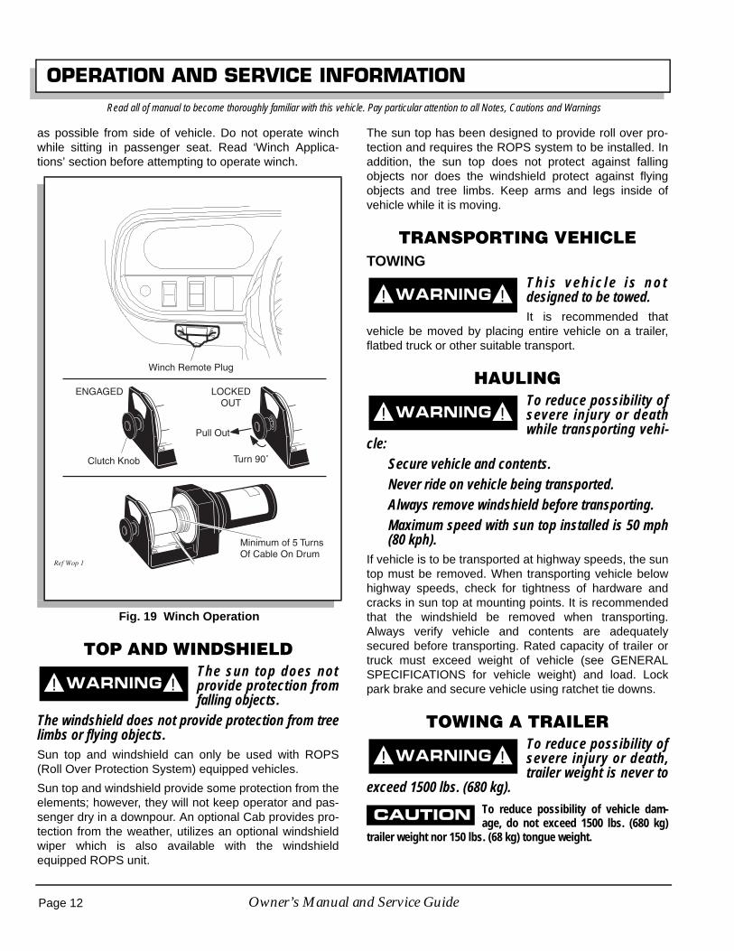
Always wear thick leather gloves when handlingwire cable.Replace frayed wire cable with a direct factoryreplacement only.Never operate winch with less than five (5) fullturns of cable around drum (Ref. Fig. 19 on page12).If winch motor stalls from overloading, do notcontinue applying power to winch. The wire cablemay become overstressed.Do not attempt to pull loads exceeding 1500 lbs.(680 kg).To pull out cable, free spool clutch knob must beused. Pull out and rotate knob. If cable is underany load, clutch may not release easily. Jog outsome cable to release tension and operate clutch.
Fig. 16 Do Not Pull at Angle
Correct
Incorrect
Ref Wps 2
! !
! !
Page 10 Owner’s Manual and Service Guide

OPERATION AND SERVICE INFORMATIONRead all of manual to become thoroughly familiar with this vehicle. Pay particular attention to all Notes, Cautions and Warnings
Pull out desired amount of cable and secure.Engage drum by rotating knob until it snaps inplace. Never operate winch unless clutch isengaged.
To prevent damage to wire cable, never hookcable to itself. Always use a nylon sling (Ref. Fig.18 on page 11).Stay clear of winch, cable and cable hook. Place aheavy cloth, jacket or blanket over cable to act asa damper should cable break when operatingwinch (Ref. Fig. 18 on page 11).
Remember that winch operation with engine offwill drain battery and may leave insufficient powerto start vehicle. Always let engine idle while usingwinch.When operating winch, keep entire area in view.
Never release free spool clutch while cable isunder load.
Never work around winch drum or cable undertension.
Unplug winch remote control before working onwinch drum in order to prevent inadvertent opera-tion.
Take up slack in cable slowly. Stop winch beforecable becomes tight and inspect all attachmentssuch as winch attachment, hook attachment,nylon sling (if required) and load attachment.
Plug winch remote control into receptacle located ondash panel (Ref. Fig. 19 on page 12).
To unwind cable, locate clutch knob on winch (Ref. Fig.19 on page 12). Pull out knob and rotate 90° to lock out.Using handsaver bar, pull cable from winch drum. Leaveat least five turns of cable on drum. Engage drum byturning clutch knob 90°, returning it to original position.
To wind cable, use handsaver bar to keep tension oncable while activating remote. When winding cable,make sure it winds tightly and evenly onto drum leavingno gaps that could cause premature wear to cable. Whenusing winch under a load, operate remote control as far
Fig. 17 Mounting Winch
ClevisPin
SpringPin
Winch shown mounted at front of vehicle
Ref Wmt 2
Fig. 18 Use Nylon Sling and Install a Damper when Winching
Ref Wca 3
NylonSling
Damper
Page 11Owner’s Manual and Service Guide
OPERATION AND SERVICE INFORMATIONRead all of manual to become thoroughly familiar with this vehicle. Pay particular attention to all Notes, Cautions and Warnings
as possible from side of vehicle. Do not operate winchwhile sitting in passenger seat. Read ‘Winch Applica-tions’ section before attempting to operate winch.
TOP AND WINDSHIELDThe sun top does notprovide protection fromfalling objects.
The windshield does not provide protection from treelimbs or flying objects. Sun top and windshield can only be used with ROPS(Roll Over Protection System) equipped vehicles.
Sun top and windshield provide some protection from theelements; however, they will not keep operator and pas-senger dry in a downpour. An optional Cab provides pro-tection from the weather, utilizes an optional windshieldwiper which is also available with the windshieldequipped ROPS unit.
The sun top has been designed to provide roll over pro-tection and requires the ROPS system to be installed. Inaddition, the sun top does not protect against fallingobjects nor does the windshield protect against flyingobjects and tree limbs. Keep arms and legs inside ofvehicle while it is moving.
TRANSPORTING VEHICLETOWING
T h i s v e h i c l e i s n o tdesigned to be towed.It is recommended that
vehicle be moved by placing entire vehicle on a trailer,flatbed truck or other suitable transport.
HAULINGTo reduce possibility ofsevere injury or deathwhile transporting vehi-
cle:Secure vehicle and contents.Never ride on vehicle being transported.Always remove windshield before transporting.Maximum speed with sun top installed is 50 mph(80 kph).
If vehicle is to be transported at highway speeds, the suntop must be removed. When transporting vehicle belowhighway speeds, check for tightness of hardware andcracks in sun top at mounting points. It is recommendedthat the windshield be removed when transporting.Always verify vehicle and contents are adequatelysecured before transporting. Rated capacity of trailer ortruck must exceed weight of vehicle (see GENERALSPECIFICATIONS for vehicle weight) and load. Lockpark brake and secure vehicle using ratchet tie downs.
TOWING A TRAILERTo reduce possibility ofsevere injury or death,trailer weight is never to
exceed 1500 lbs. (680 kg).To reduce possibility of vehicle dam-age, do not exceed 1500 lbs. (680 kg)
trailer weight nor 150 lbs. (68 kg) tongue weight.
Fig. 19 Winch Operation
Winch Remote Plug
Ref Wop 1
Pull Out
ENGAGED
Clutch Knob
LOCKEDOUT
Turn 90˚
Minimum of 5 Turns Of Cable On Drum
! !
! !
! !
! !
Page 12 Owner’s Manual and Service Guide

OPERATION AND SERVICE INFORMATIONRead all of manual to become thoroughly familiar with this vehicle. Pay particular attention to all Notes, Cautions and Warnings
Vehicle may be equipped with a receiver that accepts astandard 2" ball hitch. Trailer range of motion is limited bythe ball and hitch and should not be used on rough trailsor over objects such as logs, large rocks, holes, etc.
Never install non-factory baskets or extensions in hitchreceivers (front or rear). Such items change performancecharacteristics of vehicle and result in unsafe handling,possible roll over or vehicle damage.
Remember a loaded trailer always reduces overallcapacity of vehicle.
At no time should tongue weight be more than 150 lbs(68 kg).
The maximum weight that can be towed on a trailer is1500 lbs. (680 kg).
OPENING THE COWL (HOOD)To lift cowl (Ref. Fig. 20 on page 13):
• Pull down and out on both latches to clear receiv-ers mounted to frame
• Lift cowl up fully to allow catch to rest on cross-member and release cowl
To lower cowl:
• Lift cowl up fully with one hand to remove weightfrom catch
• Pull catch away from crossmember with otherhand
• Lower cowl until catch clears crossmember andcontinue lowering cowl with both hands
• Once seated on rubber bumpers, secure withlatches
DATA LABEL LOCATIONSerial number label is located on body just below airintake louvers near choke knob.
Manufacture date code and repeat of serial number areon data labels located on frame crossmember under bed.See LOAD BED on page 8.
Design changes take place on an ongoing basis. In orderto obtain correct components for vehicle, manufacturedate code, serial number and vehicle model must be pro-vided when ordering service parts.
Fig. 20 Unlatching Cowl
Ref Lco 1
Latches
Catch
LatchReceiver
Page 13Owner’s Manual and Service Guide

OPERATION AND SERVICE INFORMATIONRead all of manual to become thoroughly familiar with this vehicle. Pay particular attention to all Notes, Cautions and Warnings
MAINTENANCETo reduce possibility ofsevere injury or deathfrom improper servicing
techniques:Do not attempt any type of servicing operationsbefore reading and understanding all notes, cau-tions and warnings in this manual.
Wear eye protection when working onvehicle. Use extra care when workingaround batteries, or using solvents orcompressed air.
Turn off all electrical loads from battery beforeremoving battery wires.
Wrap wrenches with vinyltape to reduce possibility of adropped wrench ‘shorting
out’ a battery, which could result in an explosion.Remove and ground spark plug wires and discon-nect battery at negative terminal before servicing.Treat all electrolyte spills to body and eyes withextended flushing with clear water. Contact a phy-sician immediately. Any electrolyte spills shouldbe neutralized with a solution of 2 teaspoons (10ml) sodium bicarbonate (baking soda) dissolvedin 1 quart (1 liters) of water and flushed withwater.Insulate metal aerosol containers of battery termi-nal protectant to reduce chance of contacting bat-tery terminals which could result in an explosion.Always place entire vehicle on jack stands, disen-gage four (4) wheel drive and unlock front andrear differentials when performing a procedurerequiring engine to run with vehicle in place andtires off ground. Failure to do so will allow vehicleto pull itself off when supported by only two jackstands.
It is in the best interest of both vehicle owner and servicetechnician to carefully follow procedures recommendedin this manual. Preventative maintenance, applied at rec-ommended intervals, is the best guarantee for keepingvehicle both dependable and economical.
This vehicle will give years of satisfactory service, provid-ing it receives regular maintenance. For appropriate ser-vice intervals: See PERIODIC SERVICE SCHEDULE on
page 15. For appropriate locations See ‘LUBRICATIONPOINTS’ on page 21.
To prolong vehicle life, some mainte-nance items must be serviced more fre-
quently on vehicles used under severe driving conditions suchas extreme temperatures, extreme dust/debris conditions, fre-quent use with maximum load.
To reduce possibility of vehicle damage when servicing:• Do not lift vehicle by placing jack under front or
rear aluminum differential cases: See ‘Lifting theVehicle’ on page 17.
• Always place entire vehicle on jack stands, selecttwo (2) wheel drive and unlock both differentialswhen performing procedures requiring engine torun with vehicle in place and tires off ground. Fail-ure to do so will allow vehicle to pull itself off whensupported by only two jack stands.
• Do not operate engine with CVT drive beltremoved since engine speed is governed by thetransfer case. Doing so allows engine to exceedits maximum revolutions per minute (RPM).
To access powertrain for routine maintenance, lift seat.Additional access may be obtained by raising or remov-ing load bed. For major repair, refer to appropriate Tech-nician’s Repair and Service Manual.
Some service procedures may require vehicle to belifted. For proper lifting procedure and safety information:See ‘LIFTING THE VEHICLE’ on page 17.
! !
Page 14 Owner’s Manual and Service Guide

OPERATION AND SERVICE INFORMATIONRead all of manual to become thoroughly familiar with this vehicle. Pay particular attention to all Notes, Cautions and Warnings
PERIODIC SERVICE SCHEDULE
ITEM
BEFORE EACH USE WEEKLY
EVERY 20
HOURS
EVERY 50
HOURS
EVERY 100
HOURS
EVERY 200
HOURS
EVERY 300
HOURS
EVERY 500
HOURS
Service Brake(Pedal Pressure) Check X
(Fluid Level) Check X
(Pads & Shoes) Inspect X
(Rotors & Drums) Clean X
Park Brake Clean X X
Tires Check X X
Overall Vehicle Condition Check X
Wheels Check X
Fuel Gauge Check X
Alternator Belt Check X
Engine Fan and Cooling Fins Clean X
CVT Enclosure (Blockage)
Clean X
(Damage) Repair/Replace X
Wiring Check X
Accelerator Check X
Choke Check X
Carburetor Linkage Check X
Direction Selector Check X
Engine Oil Check X
Change X ** X
Engine Oil Filter Replace X ** X
Air Filter Check X
Clean X#
Replace X#
Spark Plugs Check X
Replace X
Idle Speed Check X**
Valve Clearance Check X** X
Fuel Filter Check X
Replace X
Combustion Chamber Clean X
Steering Check X
Fig. 21 Periodic Service Schedule
Page 15Owner’s Manual and Service Guide

OPERATION AND SERVICE INFORMATIONRead all of manual to become thoroughly familiar with this vehicle. Pay particular attention to all Notes, Cautions and Warnings
** First occurrence only # More frequently in dusty conditions
To perform service that is listed in this schedule but not described in this manual, contact a local Service Representativeor see Repair and Service Manual for this vehicle.
Some maintenance items must be serviced more frequently on vehicles used under severe driving conditions.
BASIC SERVICE PARTSTo order parts, SERVICE PARTS Department contactinformation is as follows:
In USA, Phone: 1-800-241-5855; Fax: 1-800-448-8124
Outside USA, Phone: 010-1-706-798-4311; Fax: 010-1-706-771-4609
E-Z-GO Division of TEXTRON, Inc., 1451 Marvin GriffinRoad, Augusta, Georgia USA 30906-3852
ITEM
BEFORE EACH USE WEEKLY
EVERY 20
HOURS
EVERY 50
HOURS
EVERY 100
HOURS
EVERY 200
HOURS
EVERY 300
HOURS
EVERY 500
HOURS
Tie Rods/Linkages Check X
Rear Axle Check X** X
Replace X
Muffler/Exhaust Check X
Spark Arrester Clean X
Front Axle Check X** X
Front Knuckles Check X
Front Struts Check X
Front Wheel Alignment Check X
Rear Shock Absorbers Check X
Fuel Tank Clean X
Throttle/Governor Linkage Check X
Hardware And Fasteners Check X
Tighten X
Battery Clean X
Drive Belt Check X
Front Wheel Bearings Check X
Drive shafts Lubricate X
C.V.Joints and Boots Check X
Fig. 21 Periodic Service Schedule
Air Filter Element 72944-G01Oil Filter 15400-POH-305PE
Spark Plugs ZGR5A (NGK)J16CR-U (DENSO)
Optional Alternator Belt 73561-G01CVT Belt 73965-G01
Fuse15 amp (P/N 35212-G01)20 amp (P/N 35212-G02)7.5 amp (P/N 35212-G05)
Headlight Bulb 20209-G3Tail Light Bulb #1157 (P/N 21759-G1)
Fig. 22 Basic Service Parts
Page 16 Owner’s Manual and Service Guide

OPERATION AND SERVICE INFORMATIONRead all of manual to become thoroughly familiar with this vehicle. Pay particular attention to all Notes, Cautions and Warnings
LIFTING THE VEHICLE
Tool List Qty. Required
Floor jack .................................................................... 1Jack stands ................................................................. 4Chocks ........................................................................ 4
To prevent possible inju-ry or death result ingfrom vehicle falling off
jack, be sure vehicle is on a firm and level surface.Never get under vehicle while it is supported by ajack. Use jack stands and test vehicle stability onstands. Always place chocks in front and behind thewheels not being raised. Use extreme care since vehi-cle is extremely unstable during lifting process.
To prevent possible injury ordeath from operating engine
while vehicle is raised, disengage 4 wheel drive andunlock front and rear differentials. To reduce possibil-ity of vehicle damage:Do not raise vehicle by placing jack under front or rear aluminumdifferential cases.
Do not operate engine with 4 wheel drive or either differentiallocks engaged.
Never operate engine with CVT drive belt removed.
Some servicing operations may require entire vehicle tobe raised (Ref. Fig. 23 on page 17).
Install chocks in front and behind each front wheel. Cen-ter jack under flange on long axle tube. Raise vehicle andlocate a jack stand under outer ends of rear axle tubes.
Lower jack and test stability of vehicle on two jackstands.
Center jack under front of frame. Raise vehicle and posi-tion jack stands under frame as shown.
Lower jack and test stability of vehicle on four jackstands.
Lower vehicle by reversing lifting sequence.
OILUse detergent motor oil designed for 4 stroke engines.
The oil must be of high quality and meet API SF, SGstandards.
For most conditions, 10W30 oil is recommended (Ref.Fig. 24 on page 17).
See chart for viscosity allowed in extreme temperatures(Ref. Fig. 24 on page 17).
! !
Fig. 23 Lifting the Vehicle
Fig. 24 Recommended Oil
Ref Liv 5 View From Underside of Vehicle
-20 0 20 40 60 80 100
-30 -20 -10 0 10 20 30 40C
F 0
3030
(Air Temperature)
10W-3010W-30
5W-305W-30
0
Ref Ovc 3
Page 17Owner’s Manual and Service Guide

OPERATION AND SERVICE INFORMATIONRead all of manual to become thoroughly familiar with this vehicle. Pay particular attention to all Notes, Cautions and Warnings
OIL LEVEL CHECK
To reduce possibility of engine damage,do not run engine with oil level too low.
Park vehicle on level surface, shut off engine and wait aminute for oil to settle.
Lift seat, remove dipstick and wipe clean (Ref. Fig. 25 onpage 18).
Replace dipstick and remove again. Observe level indi-cated and:
if it is between upper and lower holes, oil level is correct
if it is at or below the lower hole, remove oil fill cap andadd oil until level reaches upper hole
When finished, return dipstick and oil fill cap and lowerseat.
OIL CHANGEWith engine warm, park vehicle on level surface, shut offengine, remove key, set park brake and wait a minute foroil to settle.
Lift seat, wipe oil fill cap clean with a cloth and remove fillcap (Ref. Fig. 25 on page 18).
Place drain pan under engine.
Remove drain plug from base of engine (Ref. Fig. 26 onpage 18).
Once oil has drained, replace drain plug and, if due,change oil filter at this time (Ref. OIL CHANGE on page18).
Fill engine to upper hole on dipstick with appropriate oil(Ref. Fig. 24 on page 17).
Return oil fill cap and dipstick and lower seat.
OIL FILTER CHANGEDrain oil (Ref. OIL CHANGE on page 18).
Clean oil filter and its mount (Ref. Fig. 27 on page 19).
Place drain pan under engine and, being careful not todamage oil pressure switch, remove oil filter.
Wipe sealing surface of filter mount clean.
Apply clean, fresh oil to seal of new filter and screw filteron by hand until seal contacts filter mount. Tighten 7/8 ofa turn more. Torque specification is 16 ft. lbs. (22 Nm).
Fig. 25 Oil Fill and Level Check
Ref Olc 1
Oil Fill Cap
Dip Stick
Fig. 26 Oil Change
Ref Odp 1
Front of Vehicle
DrainPlug
Page 18 Owner’s Manual and Service Guide

OPERATION AND SERVICE INFORMATIONRead all of manual to become thoroughly familiar with this vehicle. Pay particular attention to all Notes, Cautions and Warnings
Fill engine to upper hole on dipstick with appropriate oil(Ref. OIL CHANGE on page 18).
Return oil fill cap and dipstick and lower seat.
Start engine and check for leaks.
Shut engine off, check oil level and add, if necessary, tobring level to upper hole on dipstick.
SPARK PLUGSTo reduce possibility of engine damage:
Only use recommended spark plugs.
Tighten spark plugs as instructed. Too loose can overheatengine and too tight can damage threads in cylinder head.
Inspect and replace spark plugs at intervals indicated inPeriodic Service Schedule. See ‘PERIODIC SERVICESCHEDULE’ on page 15.
Remove plug wires and clean area around plugs to pre-vent debris falling into cylinders. Use a 13/16” spark plugwrench to remove plugs.
Inspect electrodes for wear and insulator for cracks orchips. Fouled spark plugs are indicated by a wet, blackappearance. This could be caused by a dirty air filter ele-ment or other restrictions in air intake system. Incorrectlyadjusted valves, spark plug wires which are in poor con-dition or poor quality fuel could also contribute.
If reusing spark plugs, clean with wire brush.
Check gap. Gap should measure .028 - .031" (.70 - .80mm). If necessary, adjust gap being careful not to dam-age plug.
If replacing spark plugs, use only recommended type.(Ref. Fig. 22 on page 16). New plugs must be properlygapped before installation.
Install plugs by hand to reduce chance of cross-thread-ing.
• When plug seats against engine:• Tighten used plugs an additional 1/8 to 1/4 turn.• Tighten new plugs an additional 1/2 turn.
ALTERNATOR BELTVehicle may be equipped with an optional hi-output alter-nator (Ref. Fig. 28 on page 20). It provides power neces-sary to run a variety of equipment such as electricpowered tools, hi-intensity lighting, radio and winch.
ADJUSTING BELTHardware involved: 1/2" and 9/16" hex
Special Tools Required Qty.
Torque wrench, ft. lbs. ................................................. 1Belt tension gauge....................................................... 1
Inspect belt for cracking or wear. Replace if required.
Loosen top nut.
Loosen bottom bolt.
By hand or using a pry bar, pull alternator belt tight andhand tighten bottom bolt.
Check belt tension. Tighten to (Ref. Fig. 28 on page 20):
75 - 80 lbs. (34 - 36 kg) tension for an existing belt or 90- 110 lbs. (41 - 50 kg) tension for a new belt when using abelt tension gauge. Apply gauge half way between thetwo pulleys.
-or-
a maximum deflection of 1/2" (13 mm) for an existingbelt or 3/8" (1 cm) for a new belt when gauging by hand.
Tighten bolt to 9 - 11 ft. lbs. (12 - 15 Nm) torque and nutto 18 - 20 ft. lbs. (25 - 27 Nm).
Fig. 27 Oil Filter Change
Ref Ofi 1
Front of Vehicle
Page 19Owner’s Manual and Service Guide

OPERATION AND SERVICE INFORMATIONRead all of manual to become thoroughly familiar with this vehicle. Pay particular attention to all Notes, Cautions and Warnings
AIR CLEANERCANISTER TYPE AIR CLEANERAir cleaner element is accessible by unsnapping twoclips on air canister and removing cover and air filter ele-ment (Ref. Fig. 29 on page 20).
Clean inside of cover and canister.
Install element and cover the same way they wereremoved. Be sure positioning arrow on cover is pointingup and all clips are fastened securely.
CLEANING AIR FILTER ELEMENT
Do not use compressed air to clean airfilter; doing so will damage filter which
may result in damage to engine.
If element is in acceptable condition, loose dirt may beremoved by tapping filter lightly. Do not use oil on filterelement or any part of unit.
FUEL FILTERTo reduce possibility ofan explosion, do notsmoke near fuel tank or
in an area where gasoline is being handled. Do notperform procedures involving fuel system near openfire or electrical items which could produce a spark.Do not handle gasoline in an area that is not ade-quately ventilated.Always wear safety glasses to prevent possible eyeinjury from gasoline or gasoline vapor.Fuel filter is located at front of engine above fan cover(Ref. Fig. 30 on page 21).
Inspect it for dirt and/or water. Replace if significantamount is found.
To replace, use a pair of pliers to move clamps off endsof filter.
Remove hose coming from fuel tank first and plug.
Remove filter from hose going to fuel pump and discard.
Orient direction of new fuel filter according toFLOW arrow on side of filter.
Install new fuel filter and reposition clamps over inlet andoutlet.
Fig. 28 Adjusting Alternator Belt
Ref Abt 3
3/8" (1 cm) Max. Deflection for New Belt1/2" (1.3 cm) Max. Deflection for Existing Belt
Fig. 29 Air Cleaner
Air CleanerCover
Air CleanerCanister
Air FilterElement
Ref Air 4
Clip
! !
Page 20 Owner’s Manual and Service Guide

OPERATION AND SERVICE INFORMATIONRead all of manual to become thoroughly familiar with this vehicle. Pay particular attention to all Notes, Cautions and Warnings
LUBRICATION POINTSDo not use more than three (3) pumpsof grease in any grease fitting at any
one time. Excess grease may cause grease seals to fail orgrease migration into areas that could damage components.
Add no more than two or three pumps of grease to fit-tings shown (Ref. Fig. 31 on page 21). More than threepumps in a grease fitting could damage seals allowingcontamination of grease-sensitive components.
BATTERYTo reduce possibility of dischargingbattery and leaving insufficient reserve
to start vehicle, do not use accessories excessively while engineis off.
Failure to promptly charge a discharged battery will shorten itslife span.
Unless equipped with optional high output alternator, thevehicle uses a charge coil to charge battery. Battery ischarged while engine is running. Do not operate acces-sory items (such as accessory lights, radios, winch, etc.)excessively while engine is off. The charge coil is capa-ble of supplying 20 amps; therefore, operation of allaccessories could result in discharge of battery eventhough engine is running.
Discharging and recharging a battery is known as deepcycling. The battery is not a deep cycle model, but is astarting battery that is intended to maintain a full chargefrom the charging circuit. Multiple deep cycles will resultin premature failure of battery.
If battery becomes discharged, vehicle can be jumpstarted. See JUMP STARTING on page 22. After starting,promptly charge battery using a 12 volt charger rated at10 amps or less and in accordance with all instructionsprovided by the manufacturer of charger.
Fig. 30 Fuel Filter
Ref Ffi 1
Fig. 31 Lubrication Points
Ref Lub 5
Slip Joints& U-Joint
Yokes
View From Underside of Vehicle
Page 21Owner’s Manual and Service Guide

OPERATION AND SERVICE INFORMATIONRead all of manual to become thoroughly familiar with this vehicle. Pay particular attention to all Notes, Cautions and Warnings
BATTERY CLEANING
To reduce possibility of damage tovehicle or floor, neutralize acid before
rinsing battery.
To reduce possibility of damage to electrical components whilecleaning, do not use a pressure washer.
Cleaning should take place per PERIODIC SERVICESCHEDULE See ‘PERIODIC SERVICE SCHEDULE’ onpage 15.
When cleaning outside of battery and terminals, firstspray with a solution of sodium bicarbonate (bakingsoda) and water to neutralize any acid deposits beforerinsing with clear water.
Use of a water hose without first neutralizing any acid,will move acid from top of battery to other parts of vehicleor storage facility where it will attack metal, concrete orasphalt. Additionally, a conductive residue will remain onbattery and will contribute to its discharge.
To reduce possibility ofbattery explosion thatcould result in severe
injury or death, do not use metallic spray wand toclean battery and keep all smoking materials, openflame or sparks away from battery.Correct cleaning technique is to spray top and sides ofbattery with solution of sodium bicarbonate (baking soda)and clear water (Ref. Fig. 32 on page 22). Solutionshould consist of amounts shown in diagram and is bestapplied with a garden type sprayer equipped with a nonmetallic spray wand or a plastic spray bottle. In addi-tion, special attention should be paid to metal compo-nents adjacent to battery which should also be sprayedwith solution. Allow solution to sit for at least three min-utes. Use a soft bristle brush or cloth to wipe battery;removing any residue that could contribute to self dis-charge of battery. Rinse entire area with clean water. Donot use a pressure washer.
JUMP STARTINGTo reduce possibility ofsevere injury or death,fo l low jump s tar t ing
instructions explicitly.To reduce possibility of permanent damage to battery, promptlycharge a discharged battery.
Turn key switch to OFF.
Place direction selector in neutral.
Attach one end of red positive cable to positive post ofweak battery and other end to positive post of strong bat-tery (Ref. Fig. 33 on page 23).
Attach one end of black negative cable to negative postof strong battery and other end to vehicle frame.
Start vehicle as usual. Once started, disconnect cables inreverse order.
Charge battery as soon as possible (Ref. BATTERY onpage 21).
VEHICLE CLEANING AND CARECLEANING
To reduce possibility ofsevere injury or vehicledamage, read and under-
stand all instructions supplied by manufacturer ofpressure washer.
To reduce possibility of damage, do notuse pressure in excess of 700 psi (4826
kPa) when pressure washing exterior of vehicle and do not useany abrasive or reactive solvents to clean plastic parts.
It is important that proper techniques and cleaning mate-rials be used. Using excessive water pressure maycause severe injury to operator or bystander, damage toseals, plastics, seat material, body finish or electrical sys-
! !
! !
Fig. 32 Cleaning Battery
1 1/2 gallons(6 liters)
Clear Water
1/4 Cup (60 ml)Sodium Bicarbonate
(Baking Soda)
2 Gallon(7.5 liter) GardenSprayer
Ref Pns 1
1 quart(1 liter)
Clear Water
2 Teaspoons(10 ml)Sodium
Bicarbonate(Baking Soda)
PlasticSprayBottle
ORNon
MetallicWand
! !
Page 22 Owner’s Manual and Service Guide

OPERATION AND SERVICE INFORMATIONRead all of manual to become thoroughly familiar with this vehicle. Pay particular attention to all Notes, Cautions and Warnings
tem. Do not use pressure in excess of 700 psi (4800 kPa)to wash exterior of vehicle.
Clean windshield with lots of water and a clean cloth.
Normal cleaning of vinyl seats and plastic or rubber trimrequires use of a mild soap solution applied with asponge or soft brush and wipe with a damp cloth.
Removal of oil, tar, asphalt, shoe polish, etc. will requireuse of a commercially available vinyl/rubber cleaner.
Painted surfaces require frequent washing with luke-warm or cold water and mild detergent.
Occasional cleaning and waxing with non-abrasive prod-ucts designed for ‘clear coat’ automotive finishes willenhance the appearance and durability of the paintedsurfaces.
Corrosive materials used as fertilizers or for dust controlcan collect on underbody of vehicle. These materials willcause corrosion of underbody parts unless flushed occa-sionally with plain water. Thoroughly clean any areaswhere mud or other debris can collect. Sediment packedin closed areas should be loosened to ease it’s removal,taking care not to chip or otherwise damage paint.
If engine does not start or runs improperly afterwashing, remove spark plug wires (by pulling
the spark plug boots, never the wires). Dry all connections withforced air. Reinstall wires.
CARE PRODUCTSTo help maintain the vehicle there are several productsavailable through local Distributors, authorizedBranches, or the Service Parts Department.
• Touch-up paint specially formulated to match vehi-cle colors for use on both metal and molded plas-tic bodies. (P/N 28140-G** and 28432-G** forsolid colors; 75831-G** for camouflage colors)
• Battery Protectant formulated to form a long-term,flexible, non-tacky, dry coating that will not crack,peel or flake over a wide temperature range. (P/N75500-G01)
• White Lithium Grease designed to provide lubrica-tion protection in areas where staining or discolor-ing is a problem, or in areas of extremetemperature ranges. (P/N 75502-G01)
• Penetrant/Lubricant, a 4-in-1 product that pene-trates seized parts, lubricates leaving a light lubri-cating film, reduces corrosion by adhering to wetor dry surfaces and displaces moisture, sealingagainst future moisture return. (P/N 75503-G01)
• Multi-purpose Cleaner and Degreaser that con-tains natural, environmentally safe solvents. (P/N75504-G01)
• Multi-purpose Hand Cleaner is an industrialstrength cleaner containing no harsh solvents, yetgently lifts grease off hands. May be used with orwithout water. (P/N 75505-G01)
• Battery Cleaner that neutralizes battery acids anddissolves terminal corrosion and can be rinsedwith water. (P/N 75506-G01)
• Biodegradable Cleaner that breaks down greaseto be easily wiped or rinsed away. (P/N 75507-G01)
• Multi-purpose Value Pack sampler includes 4ounce (118 ml) aerosol cans of Battery Protector,Penetrant/Lubricant, White Lithium Grease, andCarburetor and Choke Cleaner. (P/N 75508-G01)
LABELS AND PICTOGRAMSVehicles are labeled with pictograms as a method of con-veying information or warnings. Appendix A illustratesand explains pictograms that appear on vehicle. Not allpictograms shown in Appendix A will be used on vehicle.
Fig. 33 Jump Starting
Ref Jmp 1
+
-
+
-StrongBattery
WeakBattery
Front ofVehicle
Page 23Owner’s Manual and Service Guide

OPERATION AND SERVICE INFORMATIONRead all of manual to become thoroughly familiar with this vehicle. Pay particular attention to all Notes, Cautions and Warnings
WHEELS AND TIRESTires are uni-directional and should never bemoved from one side of vehicle to the other.
This vehicle comes standard with low pressure, tubeless,uni-directional tires mounted on one piece wheels (Ref.Fig. 34 on page 24). Left side tires should always remainon left side of vehicle. Right side tires should alwaysremain on right side of vehicle. Uni-directional tires havean arrow on their sidewall indicating direction of rotationwhen moving forward.
TIRE INSPECTION AND INFLATION
To reduce possibility ofsevere injury or deathfrom tire separating from
wheel or exploding, use caution when inflating tiresand never exceed maximum pressure rating on side-wall of tire. Overinflation can occur quickly.Tire condition should be inspected per the PERIODICSERVICE SCHEDULE See ‘PERIODIC SERVICESCHEDULE’ on page 15. Examine for cuts, puncturesand excessive wear. Repair or replace as necessary.
Air pressure should be checked when tires are cool. If airneeds to be added, see GENERAL SPECIFICATIONSsection of this manual. Standard and optional tires shouldbe inflated to pressure designated. If pressure is not des-ignated, inflate to pressure recommended on sidewall oftire. Under no condition should inflation pressure behigher than maximum pressure listed on sidewall of tire.All four tires should have the same pressure for opti-mum handling characteristics.
Use caution when inflating tires. Due to low volume ofsmall tires, overinflation can occur in seconds. Overinfla-tion could cause tire to separate from wheel or cause tireto explode.
Be sure to install valve dust cap after checking.
REMOVAL AND INSTALLATION
To reduce possibility ofsevere injury caused bya broken socket when
removing wheels, use only sockets designed forimpact wrench use.Hardware involved: 3/4" hex lug nut
To remove, loosen lug nuts. If using an impact wrench,use only impact sockets with it. Regular sockets are notdesigned for impact pressures exerted by power tools.
Raise vehicle. See LIFTING THE VEHICLE on page 17.
Remove lug nuts and wheel.
To reduce possibility of damage, tight-en lug nuts to no more than 85 ft. lbs.
(115 Nm) torque.
Use ‘cross sequence’ pattern when tighteninglug nuts to assure even seating of wheel
against hub.
Special Tools Required Qty.
Torque wrench, ft. lbs. .................................................1
To install, place wheel onto studs with valve stem facingaway from hub (Ref. Fig. 34 on page 24). Be sure toposition wheel on hub correctly with arrow on tire indicat-ing direction of rotation when moving forward.
Add lug nuts and finger tighten.
Secure wheel by tightening lug nuts in a ‘cross sequence’pattern to 50 - 85 ft. lbs. (70 - 115 Nm) torque in 20 ft. lbs.(30 Nm) increments.
Lower vehicle.
! !
! !
Fig. 34 Wheel Tightening Sequence
Tire style may vary
1
2
3
4
'Cross Sequence'
Front ofVehicle
Rotation
Ref Whi 4
Page 24 Owner’s Manual and Service Guide

OPERATION AND SERVICE INFORMATIONRead all of manual to become thoroughly familiar with this vehicle. Pay particular attention to all Notes, Cautions and Warnings
LIGHT BULB REPLACEMENT
Replacement bulbs are available from a local Distributor,an authorized Branch or the Service Parts Department(Ref. Fig. 22 on page 16).
Locate two screws on backside of cowl that secure head-light (Ref. Fig. 35 on page 25).
Remove screws, pull headlight out and disconnect wires.
Connect wires to new headlight, install in cowl andsecure with screws previously removed.
FUSE REPLACEMENTFuses are available from a local Distributor, an autho-rized Branch or the Service Parts Department (Ref. Fig.22 on page 16).
To replace fuses, locate fuse block or individual waterresistant fuses mounted to plate under cowl (late produc-tion).
Pull out failed fuse and replace with a fuse of same typeand load rating.
SPARK ARRESTERTo reduce possibility ofsevere injury or death,al low muff ler to cool
before servicing and never operate vehicle withoutspark arrester in good condition and in place.Raise load bed.
Remove screw securing spark arrester and pull arresterfrom muffler (Ref. Fig. 36 on page 25).
Brush off carbon deposits from arrester screen withoutdamaging screen. Screen must be intact. Replace sparkarrester if screen is breached.
Install arrester on muffler and secure with screw.
PROLONGED STORAGETo reduce possibility ofsevere injury or deathresulting from a possi-
ble explosion:Do not handle fuel in an area that is not adequatelyventilated. Do not smoke near fuel tank or refuel nearopen flame or electrical items which could produce aspark.Store vehicle in a clean, dry area. Do not store insame area as a stove, furnace, water heater, or otherappliance that uses a pilot light or has a device thatcan create a spark.When refueling, inspect fuel cap for leaks or breaksthat could result in fuel spillage.Always wear safety glasses while refueling to preventpossible eye injury from gasoline or gasoline vapor.Keep hands, clothing and jewelry away from movingparts. Use care not to contact hot objects.Preparing vehicle for a prolonged storage period (30days or more) calls for a few simple steps to prevent abuild up of varnish and gum in carburetor and corrosionin engine.
• Clean body, chassis and engine of debris, mud,chaff or grass (Ref. AIR INTAKE AND COOLINGFINS on page 26).
• Disconnect fuel hose at fuel tank and plug hose.• With proper ventilation, start engine and allow it to
run until it stops due to lack of fuel.
Fig. 35 Headlight Replacement
HeadlightBulb
Insideof Cowl
Ref Hdr 4
! !
Fig. 36 Cleaning Spark Arrester
Ref Csa 1
! !
Page 25Owner’s Manual and Service Guide

OPERATION AND SERVICE INFORMATIONRead all of manual to become thoroughly familiar with this vehicle. Pay particular attention to all Notes, Cautions and Warnings
• Add fuel stabilizer to fuel tank following instruc-tions on stabilizer container.
• Attach fuel line to tank and drive vehicle for sev-eral minutes to circulate fuel stabilizer through car-buretor.
• While engine is still warm, change oil (Ref. OILCHANGE on page 18).
• Remove spark plugs (Ref. SPARK PLUGS onpage 19) and pour about 1 oz. (30 ml) of engine oilinto each cylinder. Replace spark plugs, groundspark plug wires and use starter to turn engineover a few seconds to distribute oil.
FRONT AND REAR AXLESRear axle is provided with a lubricant level check/fill pluglocated on side of differential case. Unless leakage is evi-dent, an annual lubricant check is sufficient.
CHECKING LUBRICANT LEVELHardware involved: 7/16" hex head plug
Clean check/fill plug and area around it (Ref. Fig. 37 onpage 26).
Remove plug.
Correct lubricant level is just below bottom of threadedhole. If lubricant is to be added, use a funnel and addcorrect type lubricant slowly until it starts to seep fromhole See ‘Checking Axle Lubricant’ on page 26.
Install plug and tighten to 18 ft. lbs. (25 Nm).
To replace lubricant, a drain plug is provided at bottom ofdifferential case.
TRANSFER CASEThe transfer case is provided with an oil level check/fillplug located on passenger side at rear of case. Unlessleakage is evident, an annual check is sufficient.
CHECKING LUBRICANT LEVELHardware involved: 9/16" hex head plug
Clean check/fill plug and area around it (Ref. Fig. 38 onpage 26).
Remove plug.
Correct lubricant level is just below bottom of threadedhole. If lubricant is to be added, use a funnel and addcorrect type lubricant slowly until it starts to seep fromhole See ‘Checking Transfer Case Lubricant’ on page26..
Install plug and tighten to 20 - 25 ft. lbs. (27 - 34 Nm).
To replace lubricant, a drain plug is provided at bottom oftransfer case.
AIR INTAKE AND COOLING FINSTo reduce possibility offire, engine parts shouldbe kept clean to reduce
risk of overheating and ignition of accumulateddebris.Fig. 37 Checking Axle Lubricant
Check/Fill Plug
Drain PlugRef Raf 4
Fig. 38 Checking Transfer Case Lubricant
Drain Plug
Check/Fill Plug
Ref Tcf 1
! !
Page 26 Owner’s Manual and Service Guide

OPERATION AND SERVICE INFORMATIONRead all of manual to become thoroughly familiar with this vehicle. Pay particular attention to all Notes, Cautions and Warnings
After every off road use, allow to cool and then check forbuild up of dirt and debris in air intake and cooling fins(Ref. Fig. 39 on page 27). Dirt and debris may clog theengine’s air cooling system.
Clean areas shown to prevent engine damage.
Keep linkages, springs and controls clean.
Keep area around muffler free of any combustible mate-rial.
BRAKESPERIODIC BRAKE TEST FOR HYDRAULIC BRAKES
To reduce possibility ofsevere injury or death,always evaluate pedal
travel before operating a vehicle to verify some brak-ing function is present.It is important to periodically check and maintain properbrake fluid level in master cylinder (Ref. BRAKES onpage 27). Master cylinder is located under cowl. Whenchecking fluid, wipe off any dirt from fill cap beforeremoving it to reduce possibility of contamination. Fluidlevel should be maintained at mark molded into reservoir.If fluid must be added, use only DOT 3 brake fluid andinspect system for fluid leaks.
Push brake pedal. Pedal should have some free traveland then become hard. A brake pedal that has no freetravel, excessive free travel or a spongy feel indicatesthat a brake inspection is required. A brake pedal thatoffers little resistance after it is applied indicates a leak insystem.
CAPACITIES
Fig. 39 Cleaning Air Intake and Cooling Fins
AirIntake
CoolingFins
Ref Cai 2
! !
Fuel Tank 6.7 gal (25.4 liters) unleaded, 87 octane or higher
Engine Oil1.59 quarts (1.5 liters) crankcase only1.90 quarts (1.8 liters) crankcase and filter10W30 usually. See OIL on page 17.
Front Differential 15.2 ± 1 oz. (450 ml) of 80 - 90W GL5Rear Axle 15.2 ± 1 oz. (450 ml) of 80 - 90W GL5Transfer Case 24 oz. (700 ml) MOBILFLUID 424
Fig. 40 Capacities
Page 27Owner’s Manual and Service Guide

OPERATION AND SERVICE INFORMATIONRead all of manual to become thoroughly familiar with this vehicle. Pay particular attention to all Notes, Cautions and Warnings
HARDWAREPeriodically, vehicle should be inspected for loose fasten-ers. Fasteners should be tightened in accordance withthe Torque Specifications table (Ref. Fig. 41 on page 28).
Use care when tightening fasteners and refer to Techni-cian’s Repair and Service Manual for specific torque val-ues.
Generally, three grades of hardware are used in vehicle.Grade 5 hardware can be identified by three marks onthe hexagonal bolt head and grade 8 by six marks.Unmarked hardware is Grade 2.
Fig. 41 Torque Specifications and Bolt Grades
ALL TORQUE FIGURES ARE IN FT. LBS. (Nm)
BOLT SIZE
Grade 2
1/4" 5/16" 3/8" 7/16" 1/2" 9/16" 5/8" 3/4" 7/8" 1"
Unless otherwise noted in text, tighten all hardware in accordance with this chart.This chart specifies 'lubricated' torque figures. Fasteners that are plated or lubricated when
installed are considered 'wet' and require approximately 80% of the torque required for 'dry' fasteners.
4(5)
8(11)
15(20)
24(33)
35(47)
55(75)
75(102)
130(176)
125(169)
190(258)
Grade 5
Grade 8
6(8)
13(18)
23(31)
35(47)
55(75)
80(108)
110(149)
200(271)
320(434)
480(651)
6(8)
18(24)
35(47)
55(75)
80(108)
110(149)
170(230)
280(380)
460(624)
680(922)
BOLT SIZE
Class 5.8(Grade 2)
M4 M5 M6 M8 M10 M12 M14
1(2)
2(3)
4(6)
10(14)
20(27)
35(47)
55(76.4)
Class 8.8(Grade 5)
2(3)
4(6)
7(10)
18(24)
35(47)
61(83)
97(131)
Class 10.9(Grade 8)
3(4)
6(8)
10(14)
25(34)
49(66)
86(117)
136(184)
5.8
8.8
10.9
Ref Tsp 1
Page 28 Owner’s Manual and Service Guide

Page 29
GENERAL SPECIFICATIONS
Owner’s Manual and Service Guide
GENERAL SPECIFICATIONS

GENERAL SPECIFICATIONS
ST 4X4STANDARD EQUIPMENT:
CHASSIS Welded steel, hot-dip galvanized, front hitch receiverBODY (Front) Flexible, Impact Resistant DuraShield™ Injection Molded TPE
(Thermoplastic Elastomer) with Base Coat/Clear CoatBODY (Rear) Lightweight, replaceable steel panels, plastic rear fendersBATTERY One 12 Volt Maintenance Free (340 CCA, 38 Minute Reserve)ENGINE Honda 18 H.P. (13.4 kW) 37.5 ci (614 cc) Twin Cylinder, Air Cooled, Overhead Valve,
Replaceable Oil Filter, Replaceable Dry Cartridge Air Filter with Remote Air Intake,Transistorized Magneto, Fixed Jet Bowl Carburetor, Pulse Fuel Pump
TRANSFER CASE Helical geared with Forward, Reverse and Ground Speed GovernorTRANSMISSION Automatic Continuously Variable Transmission (CVT)FUEL TANK 6.7 Gallon (25.4 Liters) TankBRAKES (FRONT) Dual Front Wheel, Hydraulic 8" (203 mm) Disc BrakesBRAKES (REAR) Dual Rear Wheel, Hydraulic 6.3" (160 mm) Drum BrakesPARK BRAKE Hand Operated Lever with Indicator LightFRONT SUSPENSION Independent with Hydraulic StrutsREAR SUSPENSION Leaf Springs with Hydraulic Shock AbsorbersSTEERING Single Reduction Rack & PinionSEATING Cushion Foam/Vinyl Cover, Hip Restraint/Hand HoldSEATING CAPACITY Operator & 1 PassengerTOTAL LOAD CAPACITY 1500 lbs. (545 kg) Including Operator, Passenger, Accessories & CargoSPEED 25 mph (40 kph)STANDARD COLOR Recon GreenDASH PANEL Scuff Resistant Glass Fiber Reinforced Plastic (Thermoplastic Olefin) with 2 Drink HoldersTIRE Carlisle AT489, 25 x 11 - 12 (Uni-directional)TIRE PRESSURE 16 - 20 psi (110 - 138 kPa)WEIGHT (Without fuel) 1250 lbs. (567 kg)BED Rotomolded Load Bed, Inside Dimensions: 42 3/4" L X 54" W X 11" H (109 X 137 X 27 cm)OPERATING CONTROLS & Removable Key, Direction Selector, Electric Fuel Gauge, 4WD/2WD Selector with Indicator Lights,INSTRUMENTATION Electric Front & Rear Differential Locks with Indicator Lights, Hour Meter, Volt MeterMAXIMUM TRAILER WEIGHT 1500 lbs. (680 kg)
Page 30 Owner’s Manual and Service Guide

GENERAL SPECIFICATIONS
Fig. 42 Vehicle Dimensions
Fig. 43 Vehicle Incline Specifications
Front43 3/8" (110 cm)
Rear43 3/4" (111 cm)
76" (193 cm)
112" (285 cm)
50"(127 cm)
16" (40.6 cm)
8 3/8" (21.3 cm)Clearance At Lowest PointOf Vehicle (On Rear Axle)
31.5"(80 cm)
54" *(137 cm)
50"(127 cm)
11"(28 cm)(Inside)
11 1/2" (29 cm)12 3/4" *(32 cm)
18 1/4"(46 cm)
9 1/2" (24 cm)Clearance At Lowest
Point On Frame
Ref Dim 3-1 Late 2005 Production Loadbed shown. Early Production Similar* Indicates Late 2005 Production Dimension
Maximum Recommended Side Tilt25% or 14˚ Max.
Maximum Recommended Ramp Grade25% or 14˚ Max.
Ref Dim 3-2
Page 31Owner’s Manual and Service Guide
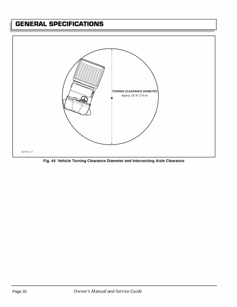
GENERAL SPECIFICATIONS
Fig. 44 Vehicle Turning Clearance Diameter and Intersecting Aisle Clearance
TURNING CLEARANCE DIAMETER
Approx. 25'-6" (7.8 m)
Ref Dim 3-3
Page 32 Owner’s Manual and Service Guide

Page 33Owner’s Manual and Service Guide
VEHICLE WARRANTIES
VEHICLE WARRANTIES

Page 34 Owner’s Manual and Service Guide
VEHICLE WARRANTIES

Page 35
VEHICLE WARRANTIES
Owner’s Manual and Service Guide
EMISSION CONTROL SYSTEM WARRANTY STATEMENT(Owner’s Defect Warranty Rights and Obligations)
Refer to the HONDA Emission Control System Warranty sheet, provided with vehicle, for information.
ENGINE OWNER WARRANTY POLICY
Refer to the Warranty sheet, provided with vehicle, for Engine Warranty information.
INTERNATIONAL WARRANTY STATEMENT
Refer to the International Warranty sheet, provided with vehicle, for information.

Page 36 Owner’s Manual and Service Guide
VEHICLE WARRANTIES
Notes:

Page 37Owner’s Manual and Service Guide
DECLARATION OF CONFORMITY
DECLARATION OF CONFORMITY(EUROPE ONLY)
Declaration of Conformity is packaged with vehicle. For additional information, contact:
Ransomes Jacobsen Limited
West Road, Ransomes Europark,
Ipswich, England, IP3 9TT
Page 38 Owner’s Manual and Service Guide
DECLARATION OF CONFORMITY
Notes:

Appendix A - 1
LABELS AND PICTOGRAMS
Owner’s Manual and Service Guide
LABELS AND PICTOGRAMS

LABELS AND PICTOGRAMS
Notes:
Appendix A - 2 Owner’s Manual and Service Guide

LABELS AND PICTOGRAMS
Fig. 45 Label Locations
75696G01
74099G01
See Following Pages For Explanation Of These Pictograms: (14)
74099-G01
72939G01
(Lift Cowl)
To release cowl,raise and holdcowl, lift leverand lower cowlcarefully
72939G01
H O2
1 2 3
PP
PP PP74093-G01
74093G01
24880G1
75696G01
See Following Pages For Explanation Of These
Pictograms: (1,23,27,18,20,22,17,15)
See Following Pages For Explanation Of These
Pictograms: (1)
See Following Pages For Explanation Of These Pictograms: (1,35)
73603G01
73601G0173605G01
73607G01
See Following Pages For
Explanation Of These
Pictograms: (61,45,62,63)
See Following PagesFor Explanation OfThese Pictograms:
(43,44,51)
73767G01
73771G01
See Following Pages For
Explanation Of These
Pictograms: (1,2,3,4,6,9,29,
36,37,54,55)
< 14˚ 25%< 14˚ 25%
73771G01
OFFON
START
73767G01
73769 G01
See Following Pages For Explanation Of These Pictograms: (52,53)
P 1 2
3
73769G01
35493G01
See Following PagesFor Explanation Of
This Pictogram: (28)
(Lift Cowl)
Pb35493-G01
74821G04 See Following Pages For Explanation Of These Pictograms: (1,2,12,10,8,11,50,7,5)
MAX14o / 25%
!
MAX1100 lbs.500 kg
MAX 5 in.12 cm
PP
MAX100 lbs.45 kg
74821G04
See Following Pages For Explanation Of These Pictograms: (56,57,58,59,60)
73777G0173777G01
71489G01
See Following PagesFor Explanation OfThese Pictograms:
(1,2)
Appendix A - 3Owner’s Manual and Service Guide

LABELS AND PICTOGRAMS
Fig. 46 Pictogram Definitions
1.
2.
4.
MAXMAX14 ° / 25 %14 ° / 25 %
5.
!
< 14 ° 25 %< 14 ° 25 %
6.
PP12.
x inx inxx cmxx cm
MAX LOADMAX LOADXXX LBSXXX LBSXXX KGXXX KG13.
!
< 14 ° 25 %< 14 ° 25 %
9.
11.
7.
MAX MAXxxx lbs.xxx lbs.xxx kgxxx kg
10.
MAX MAXxx inxx inxx cmxx cm8.
!
3.
WARNINGDO NOT OPERATEUNDER THE INFLUENCEOF DRUGS OR ALCOHOL
14.
WARNING
READ MANUAL
WARNINGUSE CAUTIONIN INCLEMENTWEATHER
MAXIMUM CROSSHILL/RAMP ANGLEAS SPECIFIED
WARNINGMAXIMUM CROSSHILL/RAMP ANGLEAS SPECIFIED
LOAD WITHHIGH CENTEROF GRAVITYCOULD RESULTIN TIP OVER
LOADCENTEROF GRAVITY,MAXIMUMHEIGHT
WARNINGREAD MANUALFOR MAXIMUMLOAD BEDCAPACITY.MAXIMUMRAMP/HILL
SECURE LOADAS FAR FORWARDAS POSSIBLEMAXIMUM LOADBED CAPACITY
DO NOT RIDE INLOAD BED
DANGER OFEXPLOSIONDO NOT FILLGAS CANIN LOAD BED
WARNING MAXIMUM LAOD & CENTER OF GRAVITY.KEEP LOAD AS FAR FORWARD AS POSSIBLE.DO NOT RIDE IN LOAD BED
KEEP HANDS & FINGERS AWAY FROM DUMP BED.DO NOT STAND BEHIND DUMP BED
Appendix A - 4 Owner’s Manual and Service Guide

LABELS AND PICTOGRAMS
Fig. 47 Pictogram Definitions
26.
27.
1 3H O2PP15.
2
PP16.
PP18.
PP17.
23.
21.
22.
24.
25.
19.
20.
28.
29.
30.
31.
32.
33.
34.
35.
CLEAN UP GASOLINE SPILLS WITH WATER BEFORESTARTING ENGINE
UNLEADGASOLINE
DO NOTSPILL FUELON A HOTENGINE
GROUNDFUEL PUMP
LOW OIL PRESSURE
NEGATIVEGROUNDBATTERY
DO NOT CONNECTPOSITIVE BATTERYTERMINAL TO GROUND
SHORTING BATTERYTERMINALS MAYCAUSE EXPLOSION
NOTAMPERING.KEEP HANDSOUT
WARNINGCORROSIVE
WARNINGEXPLOSIVE
WARNINGLETHALVOLTAGE
DO NOTEXPOSETO FLAME
DO NOTDISPOSE OFBATTERIESIN LANDFILL
DO NOTDRIVE ONHIGHWAY
WINDSHIELDSDO NOTPROVIDEPROTECTIONFROMFLYING OBJECTS
BATTERIES AREHEAVY.USE CARE LIFTING
USE INSULATEDTOOLS
WEAR EYEPROTECTION
NO SMOKING
HOT SURFACE
Appendix A - 5Owner’s Manual and Service Guide

LABELS AND PICTOGRAMS
Fig. 48 Pictogram Definitions
36.
37.
F
38.
42.
R
39.
P
F
40.
P
N
41.
ON43.
OFF44.
45.
46.
47.
48.
49.
50.
51. START
52.
P
53.
1 2
3
OPERATEFROMDRIVER’S SIDEONLY
KEEP ARMSAND LEGSWITHIN VEHICLE
TO OPERATE VEHICLE IN FORWARD:* TURN KEY TO ON* MOVE DIRECTION SELECTOR TO FORWARD* DEPRESS ACCELERATOR PEDAL AND ACCELERATE SMOOTHLY
TO OPERATE VEHICLE IN REVERSE:* TURN KEY TO ON* MOVE DIRECTION SELECTOR TO REVERSE* AN AUDIBLE DEVICE WILL SOUND* DEPRESS ACCELERATOR PEDAL AND ACCELERATE SMOOTHLY
TO LEAVE A GASOLINE POWEREDVEHICLE IN PARK:* APPLY PARKING BRAKE* TURN KEY TO OFF* MOVE DIRECTION SELECTOR TO FORWARD
TO LEAVE AN ELECTRIC POWEREDVEHICLE IN PARK:* APPLY PARKING BRAKE* TURN KEY TO OFF* MOVE DIRECTION SELECTOR TO NEUTRAL
PULL HANDLE UP,PUSH BUTTON IN,PUSH HANDLE DOWNTO RELEASE PARK BRAKE
PULL HANDLE UPTO ENGAGE PARKBRAKE
ENGINECRANKINGPOSITION
MAXIMUMTAILGATELOAD
WARNINGKEEP ENTIRE BODYINSIDE CAR
DIFFERENTIALLOCKED
LOCKED
UNLOCKED
KEEP CLEARHAND ORFINGERS CANBE TRAPPED
ONPOSITION
OFFPOSITION
HEADLIGHTS
Appendix A - 6 Owner’s Manual and Service Guide

LABELS AND PICTOGRAMS
Fig. 49 Pictogram Definitions
62.
63.
56.
57.
58.
59.
60.
61.
55.
54.WARNINGREAD OWNER’S MANULBEFORE OPERATINGVEHICLE IN FORWARDOR REVERSE
WARNINGREAD OWNER’S MANUALBEFORE PARKINGVEHICLE AND LEAVINGIT UNATTENDED
FORWARD
NEUTRAL
REVERSE
WARNINGREAD OWNER’S MANUALBEFORE ENGAGING TWOOR FOUR WHEEL DRIVE
PUSH TOP OF SWITCHTO LOCK DIFFERENTIAL
PUSH BOTTOM OFSWITCH TO UNLOCKDIFFERENTIAL
FRONT DIFFERENTIALLOCK SWITCH.WARNINGREAD OWNER’S MANUALBEFORE ENGAGINGFRONT DIFFERENTIALLOCK.DO NOT ENGAGE LOCKWHILE FRONT WHEELSARE TURNED ANDVEHICLE IS AT SPEED.
PUSH TOP PART OFSWITCH TO RAISE LOADBED
PUSH BOTTOM PART OFSWITCH TO LOWER LOADBED
REAR DIFFERENTIALLOCK SWITCH
AUXILIARY LIGHTS
HORN BUTTON
Appendix A - 7Owner’s Manual and Service Guide

LABELS AND PICTOGRAMS
Notes:
Appendix A - 8 Owner’s Manual and Service Guide
Check area behind thevehicle before operatingin reverse.
Make sure the direction selector is in correct positionbefore attempting to start the vehicle.
Slow down before and during turns. All turns shouldbe executed at reduced speed.
Always bring vehicle to a complete stop beforeshifting the direction selector.
See GENERAL SPECIFICATIONS for vehicle load andseating capacity.
Read and understand the following text andwarnings before attempting to service vehicle:
In any product, components will eventually fail to performproperly as the result of normal use, age, wear or abuse.It is virtually impossible to anticipate all possible compo-nent failures or the manner in which each componentmay fail.Be aware that a vehicle requiring repair indicates that thevehicle is no longer functioning as designed and there-fore should be considered potentially hazardous. Useextreme care when working on any vehicle. When diag-nosing, removing or replacing any components that arenot operating correctly, take time to consider the safety ofyourself and others around you should the componentmove unexpectedly.Some components are heavy, spring loaded, highly cor-rosive, explosive or may produce high amperage orreach high temperatures. Gasoline, carbon monoxide,battery acid and hydrogen gas could result in seriousbodily injury to the technician/mechanic and bystanders ifnot treated with the utmost caution. Be careful not toplace hands, face, feet or body in a location that couldexpose them to injury should an unforeseen situationoccur. Always use the appropriate tools listed in the tool list andwear approved safety equipment.
To prevent personalinjury or death, observethe following:
Before working on the vehicle, remove all jewelry(rings, watches, necklaces, etc.)
Be sure that no loose clothing or hair can contactmoving parts.
Use care not to touch hot objects.
Raise entire vehicle and support on jack stands beforeattempting to run or adjust powertrain.
Wear eye protection when working on or aroundvehicle. In particular, use care when working aroundbatteries, using solvents or compressed air.
Hydrogen gas is formed when charging batteries. Donot charge batteries without adequate ventilation.
Do not permit open flame or anyone to smoke in an
area that is being used for charging batteries. Aconcentration of 4% hydrogen gas or more isexplosive.
Engine exhaust gas (carbon monoxide) is deadly.Carbon monoxide is an odorless, colorless gas that isformed as a natural part of incomplete combustion ofhydrocarbon fuels. Carbon monoxide is a dangerousgas that can cause unconsciousness and ispotentially lethal.
The following are symptoms of carbon monoxideinhalation:• Dizziness• Vomiting• Intense headache• Muscular twitching• Weakness and sleepiness• Throbbing in temples
If any of these symptoms are experienced, get fresh airimmediately. Never work around or operate a vehiclein an environment that does not ventilate exhaustgases from the area.
! !
! !

Copyrighted MaterialThis manual may not be reproduced in whole or in part without the express permission of E-Z-GO Division of Textron, Inc.Technical Communications Department
Starting Model Year 2005
P/N 602080ISSUED: April 2005
E-Z-GO Division Of Textron, Inc., 1451 Marvin Griffin Road, Augusta, Georgia USA 30906-3852
TO CONTACT US
North America: Technical Assistance & Warranty Phone: 1-800-774-3946, FAX: 1-800-448-8124 Service Parts Phone: 1-888-GET-EZGO (1-888-438-3946), FAX: 1-800-752-6175
International: Phone: 010-1-706-798-4311, FAX: 010-1-706-771-4609