Embed Size (px)
Citation preview
Technical Reference Guide
Describes features for this product.
Describes the printer functions and setting methods.
Describes the pre-installed Widows settings and specifica-tions.
Describes the requirements for system development using TM-DT software.
Describes the PC-POS System interface, the control method for devices, and system development using the Thin-Client environment.
Describes this product's specifications.
M00060305Rev. F
Product Specifications
PC-POS System Development
System Development Using TM-DT Software
Windows Settings
Printer Functions and Settings
Product Overview
2
Cautions No part of this document may be reproduced, stored in a retrieval system, or transmitted in any form or by
any means, electronic, mechanical, photocopying, recording, or otherwise, without the prior written permis-sion of Seiko Epson Corporation.
The contents of this document are subject to change without notice. Please contact us for the latest informa-tion.
While every precaution has been taken in the preparation of this document, Seiko Epson Corporation assumes no responsibility for errors or omissions.
Neither is any liability assumed for damages resulting from the use of the information contained herein. Neither Seiko Epson Corporation nor its affiliates shall be liable to the purchaser of this product or third
parties for damages, losses, costs, or expenses incurred by the purchaser or third parties as a result of: accident, misuse, or abuse of this product or unauthorized modifications, repairs, or alterations to this product, or (excluding the U.S.) failure to strictly comply with Seiko Epson Corporation’s operating and maintenance instructions.
Seiko Epson Corporation shall not be liable against any damages or problems arising from the use of any options or any consumable products other than those specified as Original Epson Products or Epson Approved Products by Seiko Epson Corporation.
TrademarksEPSON is a registered trademark of Seiko Epson Corporation.Exceed Your Vision and ESC/POS are registered trademarks or trademarks of Seiko Epson Corporation.Microsoft and Windows are registered trademarks of Microsoft Corporation.Intel, Intel AtomTM are registered trademarks or trademarks of Intel Corporation in United States of America and other countries/regions.IOS is a trademark or registered trademark of Cisco in the U.S. and other countries and is used under license.AndroidTM is trademark of Google Inc. in the United States and other countries.Wi-Fi, WPATM, WPA2TM are registered trademarks or trademarks of Wi-Fi Alliance in United States of Amer-ica and other countries/regions.All other trademarks are the property of their respective owners and used for identification purpose only.
ESC/POS Proprietary Command SystemEpson took the initiative by introducing ESC/POS, a proprietary POS printer command system, which includes patented or patent pending commands and enables versatile POS system construction with high scalability. Compatible with all types of Epson POS printers and displays, this proprietary control system also offers the flexibility to easily make future upgrades. Its popularity is worldwide. ESC/POS is designed to reduce the processing load on the host computer in POS environments. It comprises a set of highly functional and efficient commands that enables the full realization of the potential of printers.
© Seiko Epson Corporation 2013-2017. All rights reserved.

3
For Safety
Key to Symbols
The symbols in this manual are identified by their level of importance, as defined below. Read the following carefully before handling the product.
WARNING
You must follow warnings carefully to avoid serious bodily injury.
CAUTION
Provides information that must be observed to prevent damage to the equipment or loss of data. Possibility of sustaining physical injuries. Possibility of causing physical damage. Possibility of causing information loss.
Provides information that must be observed to avoid damage to your equipment or a malfunction.
Provides important information and useful tips.
4
Warnings
WARNING
To avoid risk of electric shock, do not set up this product or handle cables during a thunder-storm.
Never insert or disconnect the power plug with wet hands.Doing so may result in severe shock.
Handle the power cable with care.Improper handling may lead to fire or electric shock. Do not modify or attempt to repair the cable. Do not place any heavy object on top of the cable. Avoid excessive bending, twisting, and pulling. Do not place the cable near heating equipment. Check that the plug is clean before plugging it in. Be sure to push the plug all the way in.
Be sure to use the specified power source.Connection to an improper power source may cause fire or shock.
Do not place multiple loads on the power outlet.Overloading the outlet may lead to fire or shock.
Shut down your equipment immediately if it produces smoke, a strange odor, or unusual noise.Continued use may lead to fire. Immediately unplug the equipment and contact your dealer or a Seiko Epson service center for advice.
Never attempt to repair this product yourself.Improper repair work can be dangerous.
Never disassemble or modify this product.Tampering with this product may result in injury or fire.
Do not allow foreign matter to fall into the equipment.Penetration by foreign objects may lead to fire.
If water or other liquid spills into this equipment, do not continue to use it.Continued use may lead to fire. Unplug the power cord immediately and contact your dealer or a Seiko Epson service center for advice.
Do not use aerosol sprayers containing flammable gas inside or around this product.Doing so may cause fire.

5
Cautions
Restriction of UseWhen this product is used for applications requiring high reliability/safety, such as transportation devices related to aviation, rail, marine, automotive, etc.; disaster prevention devices; various safety devices, etc.; or functional/precision devices, etc., you should use this product only after giving consideration to including fail-safes and redundancies into your design to maintain safety and total system reliability. Because this product was not intended for use in applications requiring extremely high reliability/safety, such as aerospace equipment, main communication equipment, nuclear power control equipment, or medical equipment related to direct medical care, etc., please make your own judgment on this product's suitability after a full evaluation.
CAUTION
Do not connect cables in ways other than those mentioned in this manual.Different connections may cause equipment damage or fire.
Be sure to set this equipment on a firm, stable, horizontal surface.The product may break or cause injury if it falls.
Do not use this product in locations subject to high humidity or dust levels.Excessive humidity and dust may cause equipment damage or fire.
Do not place heavy objects on top of this product. Never stand or lean on this product.Equipment may fall or collapse, causing breakage and possible injury.
Take care not to injure your fingers on the manual cutter Do not open the roll paper cover without taking the necessary precautions, as this can result
in injury from the autocutter fixed blade. To ensure safety, unplug this product before leaving it unused for an extended period. To power off the product, use the application or OS function.
Do not use the operations shown below unless the product cannot be turned off due to an application or OS problem. Doing so may cause loss of unsaved data, require OS recovery, or damage the HDD, SSD or other hardware. Forced termination by holding down the power button for approx. 4 sec. Power shutdown by turning off the circuit breaker on the distribution board or by discon-
necting the AC cable/DC cable.The same phenomenon may also occur due to power shutdown caused by power failure/tem-porary power failure.To prevent power shutdown due to power failure/temporary power failure, using an uninter-ruptible power supply (UPS) is recommended.

6
Contents■ For Safety..................................................................................................................................3
Key to Symbols.................................................................................................................................................................... 3Warnings ............................................................................................................................................................................... 4Cautions................................................................................................................................................................................. 5
■ Restriction of Use ....................................................................................................................5
■ Contents....................................................................................................................................6
Product Overview ..........................................................................................11
■ Features ................................................................................................................................. 11
■ System Outline ..................................................................................................................... 13PC-POS system ..................................................................................................................................................................13Thin-Client system ...........................................................................................................................................................14Systems that Use TM-DT software..............................................................................................................................15
■ Development Information ................................................................................................. 16Common to All Systems.................................................................................................................................................16PC-POS system ..................................................................................................................................................................16Thin-Client system ...........................................................................................................................................................17Systems that Use TM-DT software..............................................................................................................................18
Printer Functions and Settings .....................................................................19
■ Part Names and Functions ................................................................................................. 19Main Unit Front .................................................................................................................................................................19Product Rear.......................................................................................................................................................................24
■ Installing the Product.......................................................................................................... 26
Security Hook ....................................................................................................................................................................26
■ Connecting the AC Adapter ............................................................................................... 27
■ Turning Power On and Off.................................................................................................. 29
Turning Power On ............................................................................................................................................................29Turning Power On for the First Time..........................................................................................................................29Turning Power Off............................................................................................................................................................29Power Button Settings....................................................................................................................................................30Prevention of Accidental Operation of Power Button ........................................................................................30Forced Termination..........................................................................................................................................................30
■ Online and Offline................................................................................................................ 31
Online ...................................................................................................................................................................................31Offline...................................................................................................................................................................................31
■ Handling the Roll Paper...................................................................................................... 32
Changing the Paper Width ...........................................................................................................................................32
7
Installing and Replacing Roll Paper ...........................................................................................................................34Removing Jammed Paper .............................................................................................................................................36Adjusting the Roll Paper Near-End ............................................................................................................................38
■ Attaching and Setting Peripherals.................................................................................... 39
Keyboard / Mouse............................................................................................................................................................39Display..................................................................................................................................................................................39USB Printer..........................................................................................................................................................................40Network Printer.................................................................................................................................................................40Customer Display .............................................................................................................................................................40Cash Drawer .......................................................................................................................................................................42Key Input Device ..............................................................................................................................................................44Serial Communication Device .....................................................................................................................................44Powered USB Hub Unit ..................................................................................................................................................44
■ Network Settings ................................................................................................................. 45
Connect to Wired LAN ....................................................................................................................................................45Connect to Wireless LAN ...............................................................................................................................................46
■ Attaching Accessories ......................................................................................................... 48Power Button Cover ........................................................................................................................................................48Connector Cover...............................................................................................................................................................49Affixing Tape (Optional) .................................................................................................................................................51
■ Cleaning................................................................................................................................. 52Thermal Head ....................................................................................................................................................................52Case.......................................................................................................................................................................................52
■ Preparing for Transport....................................................................................................... 53
■ Setting the Memory Switches............................................................................................ 54Functions.............................................................................................................................................................................55
■ Printer Setting / Checking Modes..................................................................................... 57
Self-test mode ...................................................................................................................................................................58NV Graphics Information Print Mode........................................................................................................................59Receipt Enhancement Information Print Mode ....................................................................................................60Software Setting Mode ..................................................................................................................................................61Hexadecimal Dumping Mode .....................................................................................................................................62
Windows Settings ..........................................................................................63
■ Windows Embedded POSReady 7..................................................................................... 63Windows Initial Settings ................................................................................................................................................63Starting Up and Shutting Down Windows..............................................................................................................63Enabling or Disabling ePOS-Device ..........................................................................................................................64Speaker Volume Setting ................................................................................................................................................64Windows Hibernation.....................................................................................................................................................65Windows Recovery ..........................................................................................................................................................67Specification ......................................................................................................................................................................68
■ Windows Embedded POSReady 2009.............................................................................. 69
Windows Initial Settings ................................................................................................................................................69

8
Starting Up and Shutting Down Windows..............................................................................................................69Enabling or Disabling ePOS-Device ..........................................................................................................................70Speaker Volume Setting ................................................................................................................................................70Windows Recovery ..........................................................................................................................................................71Specification ......................................................................................................................................................................72
System Development Using TM-DT Software.............................................73
■ Systems that Use TM-DT software .................................................................................... 73Network Printer Control.................................................................................................................................................73Controlling for POS Peripherals ..................................................................................................................................74Spooler and Forward Printing .....................................................................................................................................75Software Access Point ....................................................................................................................................................81Communication Box .......................................................................................................................................................82Server Direct Print ............................................................................................................................................................84Device Data Notification................................................................................................................................................86Web Server .........................................................................................................................................................................88Method Used to Set multiple TM-DT devices ........................................................................................................90Controlling POS Peripherals from iOS Applications ............................................................................................92Controlling POS Peripherals from Android Applications...................................................................................93Controlling POS Peripherals from Web Applications ..........................................................................................94Printing from Web Service Compatible Applications..........................................................................................95Controlling POS Peripherals from Socket Communication Compatible Applications............................96
■ TM-DT Software Settings.................................................................................................... 97
Starting EPSON TMNet WebConfig............................................................................................................................97Help Screen Display.........................................................................................................................................................98Version Screen Display ...................................................................................................................................................98Updating TM-DT Software ............................................................................................................................................98Information - Current status.........................................................................................................................................99Information - System settings - Network.............................................................................................................. 100Information - System settings - Date and Time.................................................................................................. 101Settings - Web service settings - Startup settings............................................................................................. 101Settings - Web service settings - Printer ............................................................................................................... 102Settings - Web service settings - Customer Display......................................................................................... 103Settings - Web service settings - Key input device............................................................................................ 104Settings - Web Service settings - Serial communication Device.................................................................. 105Settings - Web Service settings - Other Device .................................................................................................. 106Settings - Web service settings - Control Script - Add/delete ....................................................................... 106Settings - Web service settings - Print Settings - Spooler............................................................................... 107Settings - Web Service settings - Web Content - Update settings............................................................... 108Settings - Web service settings - Server access - Direct Print ........................................................................ 109Settings - Web Service settings - Server access - Status Notification ......................................................... 110Settings - Web Service settings - Server access - Device Data Notification ............................................. 111Settings - System settings - Network - Wired LAN - TCP/IP ............................................................................ 112Settings - System settings - Network - Wireless LAN........................................................................................ 113Settings - System settings - Network - Wireless LAN - TCP/IP ....................................................................... 114Settings - System settings - Security - SSL ........................................................................................................... 114Settings - System settings - Web access - Proxy settings................................................................................ 115Settings - System settings - Web access - Server authentication................................................................. 115Settings - System settings - Access Point - Software access point settings ............................................. 116

9
Settings - System settings - Date and time - Time settings............................................................................ 116Settings - System settings - Power - Shutdown settings ................................................................................ 117Settings - Admin settings - Maintenance - Store restore settings ............................................................... 117Settings - Admin settings - Maintenance - Initialization................................................................................. 123Settings - Admin settings - Maintenance - Log .................................................................................................. 123Settings - Admin settings - Maintenance - Update Web service function................................................ 124Settings - Admin settings - Maintenance - Deployment ................................................................................ 125Settings - Admin settings - Admin information - Admin information ....................................................... 125Settings - Admin settings - Admin information - Password........................................................................... 126
■ TM-DT Software Specification ......................................................................................... 127
Controllable printer...................................................................................................................................................... 127
PC-POS System Development.................................................................... 128
■ PC-POS System Development ......................................................................................... 128
Interface............................................................................................................................................................................ 128
■ How to Control Peripherals .............................................................................................. 129Printer................................................................................................................................................................................ 129Cash drawer..................................................................................................................................................................... 129Customer display........................................................................................................................................................... 129Other devices.................................................................................................................................................................. 129
■ Software and Manuals ...................................................................................................... 130
Development kit............................................................................................................................................................ 130Driver ................................................................................................................................................................................. 130Utility ................................................................................................................................................................................. 131Others................................................................................................................................................................................ 131
■ System Development using the Thin-Client Environment......................................... 132
Desktop Virtualization................................................................................................................................................. 132Application Virtualization........................................................................................................................................... 132
Product Specifications................................................................................ 133
■ Computer Specifications .................................................................................................. 133N2600 CPU model......................................................................................................................................................... 133N2800 CPU model......................................................................................................................................................... 135D2550 CPU model......................................................................................................................................................... 136
■ Printer Specifications ........................................................................................................ 137Printing Specifications................................................................................................................................................. 137Character Specifications ............................................................................................................................................. 138Printable Area ................................................................................................................................................................. 139Printing and Cutting Positions ................................................................................................................................. 141Roll Paper Specifications ............................................................................................................................................ 142

10
■ Power supply capacity for external devices.................................................................. 143
■ Environmental Conditions ............................................................................................... 143
■ External Dimensions ......................................................................................................... 144
■ AC Adapter Specifications................................................................................................ 147
■ Option .................................................................................................................................. 147
■ Setting Items for Software Setting Mode...................................................................... 148
■ Character Code Tables....................................................................................................... 150
11
Chapter 1 Product Overview
1
Product OverviewThis chapter describes features of this product.
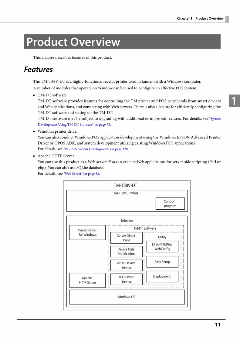
FeaturesThe TM-T88V-DT is a highly-functional receipt printer used in tandem with a Windows computer.A number of modules that operate on Window can be used to configure an effective POS System. TM-DT software
TM-DT software provides features for controlling the TM printer and POS peripherals from smart devices and Web applications, and connecting with Web servers. There is also a feature for efficiently configuring the TM-DT software and setting up the TM-DT. TM-DT software may be subject to upgrading with additional or improved features. For details, see "System Development Using TM-DT Software" on page 73.
Windows printer driverYou can also conduct Windows POS application development using the Windows EPSON Advanced Printer Driver or OPOS ADK, and system development utilizing existing Windows POS applications.For details, see "PC-POS System Development" on page 128.
Apache HTTP ServerYou can use this product as a Web server. You can execute Web applications for server-side scripting (Perl or php). You can also use SQLite database. For details, see "Web Server" on page 88.
TM-T88V-DTTM-T88V (Printer)
Control program
Software
TM-DT Software
Utility
EPSON TMNet WebConfig
Deployment
Server Direct Print
ePOS-Print Service
ePOS-Device Service
Device Data Notification
Windows OS
Printer driver for Windows
Apache HTTP Server
Easy Setup

12
Chapter 1 Product Overview
1
The printer has the following features. Space-saving design through integrating computer with printer. Interfaces for connecting with peripherals (USB x6, serial x1, DisplayPort x1 *1, VGA x1) Printing and control of peripherals from smart device applications *2 or Web applications. Server direct print function
The server direct print functions allows print data to be directly obtained and printing results to be notified from the Web server.
1 Not equipped on all models. 2 TM-DT software Ver.3.0 or later.
13
Chapter 1 Product Overview
1
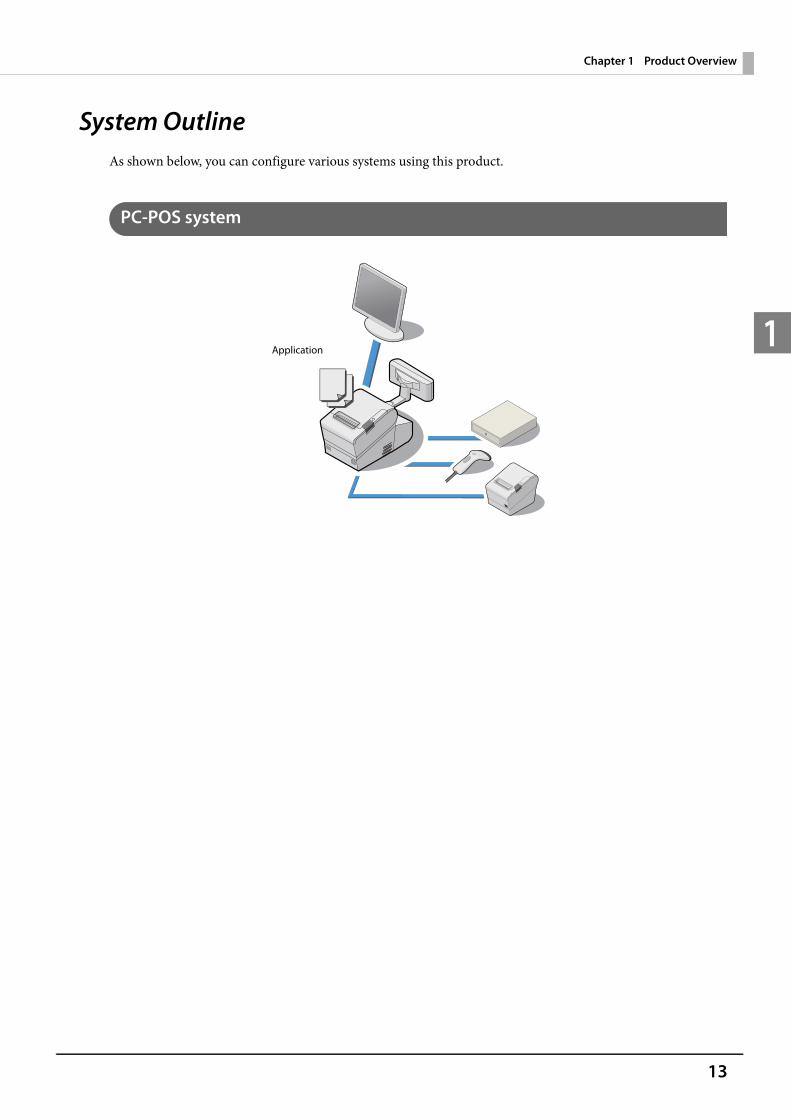
System OutlineAs shown below, you can configure various systems using this product.
PC-POS system
Application

14
Chapter 1 Product Overview
1
Thin-Client system
Virtual Desktop Infrastructure (VDI)
Application virtualization system
Application
Guest OS
Server
Display
Device control
Guest OS desktop
Application
Guest OSDisplay
Device control
Guest OS desktop
Application
OS data
Server
Application
Client OS
Application
Client OS
Application
OS data

15
Chapter 1 Product Overview
1
Systems that Use TM-DT software
Systems that implemented application in the smart device (TM-DT Software Ver.3.0 or later)
Web application system
Server Direct Print system
Application
Application
Browser
Database
Application
Notice of printing results
Acquisition of print data
16
Chapter 1 Product Overview
1
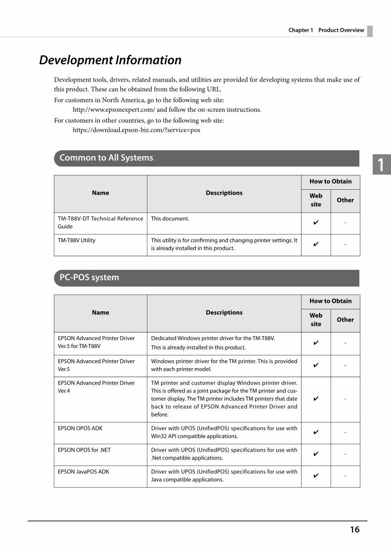
Development InformationDevelopment tools, drivers, related manuals, and utilities are provided for developing systems that make use of this product. These can be obtained from the following URL.For customers in North America, go to the following web site:
http://www.epsonexpert.com/ and follow the on-screen instructions.For customers in other countries, go to the following web site:
https://download.epson-biz.com/?service=pos
Common to All Systems
PC-POS system
Name Descriptions
How to Obtain
Website
Other
TM-T88V-DT Technical Reference Guide
This document.✔ -
TM-T88V Utility This utility is for confirming and changing printer settings. It is already installed in this product.
✔ -
Name Descriptions
How to Obtain
Website
Other
EPSON Advanced Printer Driver Ver.5 for TM-T88V
Dedicated Windows printer driver for the TM-T88V.
This is already installed in this product.✔ -
EPSON Advanced Printer Driver Ver.5
Windows printer driver for the TM printer. This is provided with each printer model.
✔ -
EPSON Advanced Printer Driver Ver.4
TM printer and customer display Windows printer driver. This is offered as a joint package for the TM printer and cus-tomer display. The TM printer includes TM printers that date back to release of EPSON Advanced Printer Driver and before.
✔ -
EPSON OPOS ADK Driver with UPOS (UnifiedPOS) specifications for use with Win32 API compatible applications.
✔ -
EPSON OPOS for .NET Driver with UPOS (UnifiedPOS) specifications for use with .Net compatible applications.
✔ -
EPSON JavaPOS ADK Driver with UPOS (UnifiedPOS) specifications for use with Java compatible applications.
✔ -
17
Chapter 1 Product Overview
1
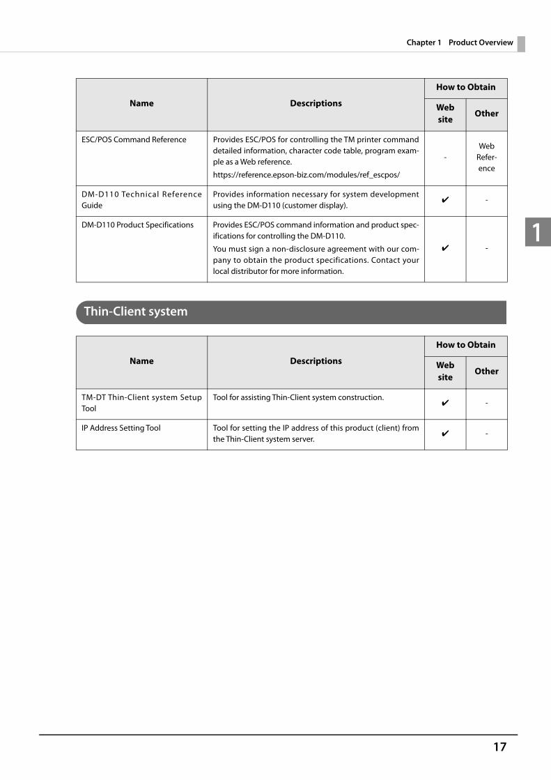
Thin-Client system
ESC/POS Command Reference Provides ESC/POS for controlling the TM printer command detailed information, character code table, program exam-ple as a Web reference.
https://reference.epson-biz.com/modules/ref_escpos/
-Web
Refer-ence
DM-D110 Technical Reference Guide
Provides information necessary for system development using the DM-D110 (customer display).
✔ -
DM-D110 Product Specifications Provides ESC/POS command information and product spec-ifications for controlling the DM-D110.
You must sign a non-disclosure agreement with our com-pany to obtain the product specifications. Contact your local distributor for more information.
✔ -
Name Descriptions
How to Obtain
Website
Other
TM-DT Thin-Client system Setup Tool
Tool for assisting Thin-Client system construction.✔ -
IP Address Setting Tool Tool for setting the IP address of this product (client) from the Thin-Client system server.
✔ -
Name Descriptions
How to Obtain
Website
Other

18
Chapter 1 Product Overview
1
Systems that Use TM-DT software
1 TM-DT Software Ver.2.5 or later2 TM-DT Software Ver.3.0 or later
Name Descriptions
How to Obtain
Website
Other
ePOS-Device SDK Software development kit for controlling the printer and peripherals from Web applications and smart device appli-cations. ePOS-Device SDK includes the following packages.
ePOS-Device SDK for iOS *1
ePOS-Device SDK for Android *1
ePOS-Device SDK for JavaScript
✔
Web Refer-ence
ePOS-Device XML User’s Manual Manual describing the method for transmitting XML data from applications via socket communication to control printing and peripherals.
✔ -
ePOS-Print XML User’s Manual Manual describing the method for using Web services from applications to conduct printing.
✔ -
Server Direct Print User’s Manual Manual describing the method for developing systems using server direct print.
✔ -
Device Data NotificationUser’s Manual *2
Manual describing the method for developing systems using device data notification.
✔ -
Deployment Guide *2 This guide includes the information needed to configure settings for multiple products efficiently.
✔ -

19
Chapter 2 Printer Functions and Settings
2
Printer Functions and SettingsThis chapter describes the printer functions and setting methods.
Part Names and Functions
Main Unit Front
Name Description
Power button Turns this product power on or off.
Printer reset button Resets this product's printer. This product's computer is not reset.
Manual cutter A cutter for cutting the roll paper by hand.
Cover open button Opens the roll paper cover.
Cutter cover If there is a paper jam in the printer, open the cover and remove the paper.
Customer display (optional) Displays characters from applications.
Feed button Pressing this button once feeds the roll paper by one line. Holding this button down feeds the roll paper continuously.
Roll paper cover
Manual cutter
Cutter cover
Controller LED
Printer reset buttonPower button
Cover button
Feed button
Customer display(option)
Connector cover
Printer LED
20
Chapter 2 Printer Functions and Settings
2
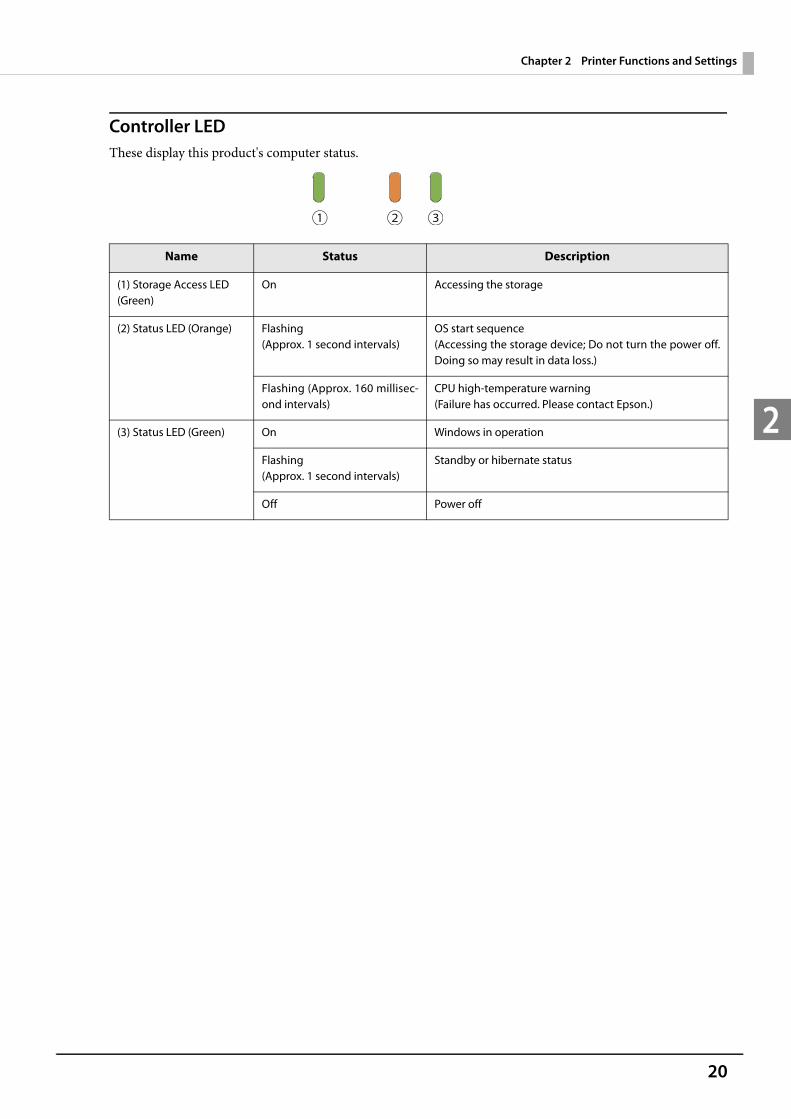
Controller LEDThese display this product's computer status.
Name Status Description
(1) Storage Access LED (Green)
On Accessing the storage
(2) Status LED (Orange) Flashing (Approx. 1 second intervals)
OS start sequence(Accessing the storage device; Do not turn the power off. Doing so may result in data loss.)
Flashing (Approx. 160 millisec-ond intervals)
CPU high-temperature warning(Failure has occurred. Please contact Epson.)
(3) Status LED (Green) On Windows in operation
Flashing (Approx. 1 second intervals)
Standby or hibernate status
Off Power off
21
Chapter 2 Printer Functions and Settings
2
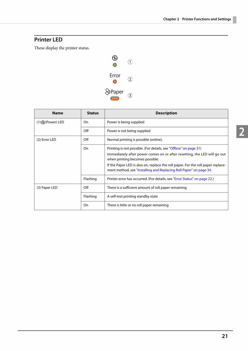
Printer LEDThese display the printer status.
Name Status Description
(1) (Power) LED On Power is being supplied
Off Power is not being supplied
(2) Error LED Off Normal printing is possible (online).
On Printing is not possible. (For details, see "Offline" on page 31)
Immediately after power comes on or after resetting, the LED will go out when printing becomes possible.
If the Paper LED is also on, replace the roll paper. For the roll paper replace-ment method, see "Installing and Replacing Roll Paper" on page 34.
Flashing Printer error has occurred. (For details, see "Error Status" on page 22.)
(3) Paper LED Off There is a sufficient amount of roll paper remaining
Flashing A self-test printing standby state
On There is little or no roll paper remaining
22
Chapter 2 Printer Functions and Settings
2
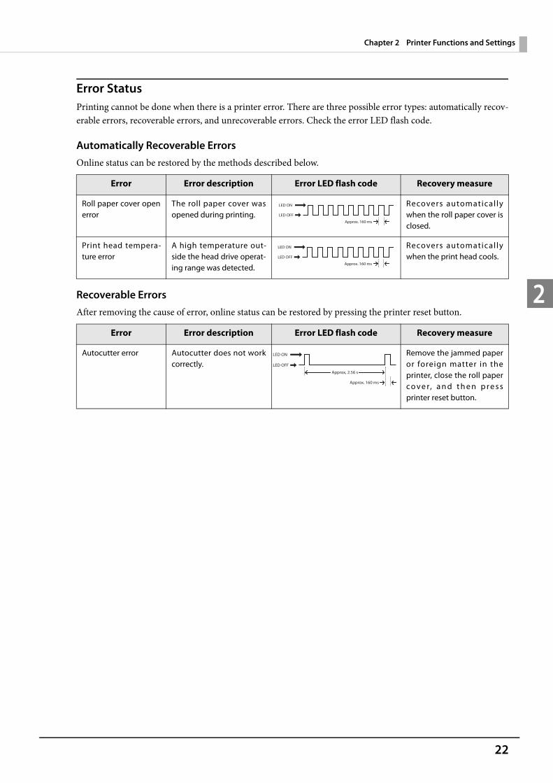
Error StatusPrinting cannot be done when there is a printer error. There are three possible error types: automatically recov-erable errors, recoverable errors, and unrecoverable errors. Check the error LED flash code.
Automatically Recoverable Errors Online status can be restored by the methods described below.
Recoverable Errors After removing the cause of error, online status can be restored by pressing the printer reset button.
Error Error description Error LED flash code Recovery measure
Roll paper cover open error
The roll paper cover was opened during printing.
Recovers automatical ly when the roll paper cover is closed.
Print head tempera-ture error
A high temperature out-side the head drive operat-ing range was detected.
Recovers automatical ly when the print head cools.
Error Error description Error LED flash code Recovery measure
Autocutter error Autocutter does not work correctly.
Remove the jammed paper or foreign matter in the printer, close the roll paper c o v e r, a n d t h e n p r e s s printer reset button.
LED ON
LED OFF
Approx. 160 ms
LED ON
LED OFF
Approx. 160 ms
Approx, 2.56 s
LED ON
LED OFF
Approx. 160 ms

23
Chapter 2 Printer Functions and Settings
2
Unrecoverable Errors If an unrecoverable error occurs, immediately press the printer reset button. If the same error still occurs, turn the printer power off. Since it is possible a failure has occurred in the printer, contact your dealer or a Seiko Epson service center for advice.
CAUTION
If an unrecoverable error occurs after resetting the printer, immediately turn the printer power off.
Error Error description Error LED flash code
Memory R/W error After R/W checking, the printer does not work correctly.
High voltage error The power supply voltage is extremely high.
Low voltage error The power supply voltage is extremely low.
CPU execution error The CPU is executing an incorrect address.
Internal circuit connec-tion error
Internal circuits are not connected correctly.
LED ON
LED OFF
Approx. 160 ms
LED ON
LED OFF
Approx. 160 ms
LED ON
LED OFF
Approx. 160 ms
LED ON
LED OFF
Approx. 160 ms
Approx. 2.56 s
LED ON
LED OFF
Approx. 160 ms
24
Chapter 2 Printer Functions and Settings
2
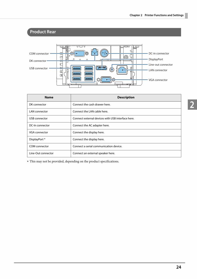
Product Rear
This may not be provided, depending on the product specifications.
Name Description
DK connector Connect the cash drawer here.
LAN connector Connect the LAN cable here.
USB connector Connect external devices with USB interface here.
DC-In connector Connect the AC adapter here.
VGA connector Connect the display here.
DisplayPort * Connect the display here.
COM connector Connect a serial communication device.
Line-Out connector Connect an external speaker here.
COM connector
DK connector
USB connector
VGA connector
LAN connector
Line-out connector
DisplayPort
DC-in connector
25
Chapter 2 Printer Functions and Settings
2
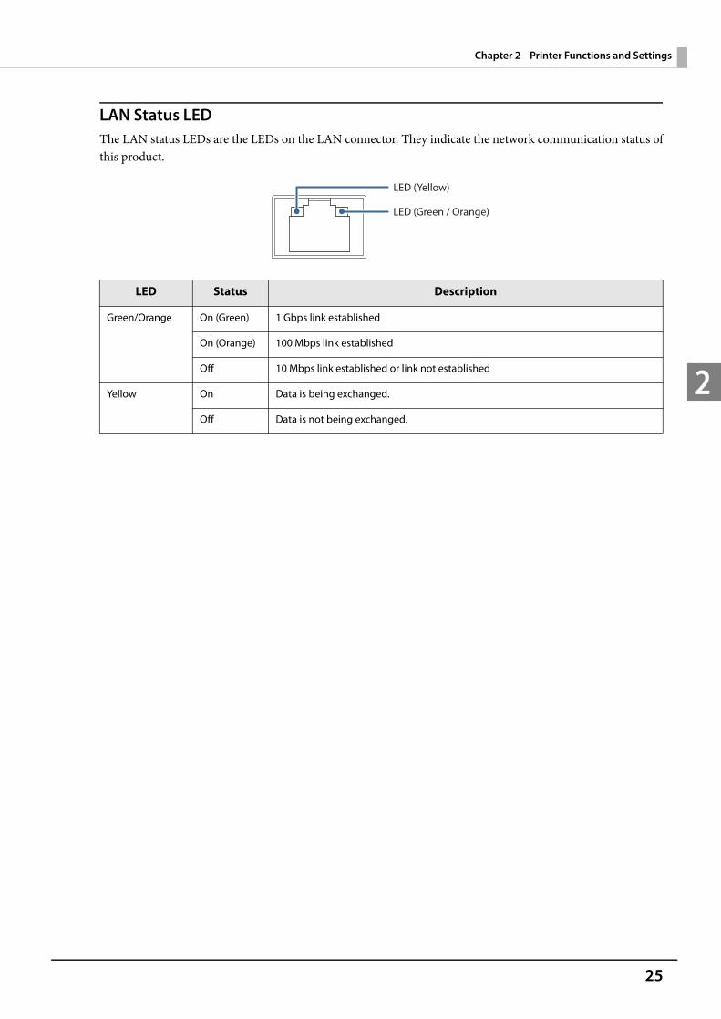
LAN Status LEDThe LAN status LEDs are the LEDs on the LAN connector. They indicate the network communication status of this product.
LED Status Description
Green/Orange On (Green) 1 Gbps link established
On (Orange) 100 Mbps link established
Off 10 Mbps link established or link not established
Yellow On Data is being exchanged.
Off Data is not being exchanged.
LED (Yellow)
LED (Green / Orange)
26
Chapter 2 Printer Functions and Settings
2
Installing the Product Display caution regarding the following points when installing the Product. The Product must be installed horizontally on a flat surface (not tilted). Do not place the product in dusty locations. Do not knock or strike the product. This may cause defective print. Do not catch cables and do not place foreign matter under the product.
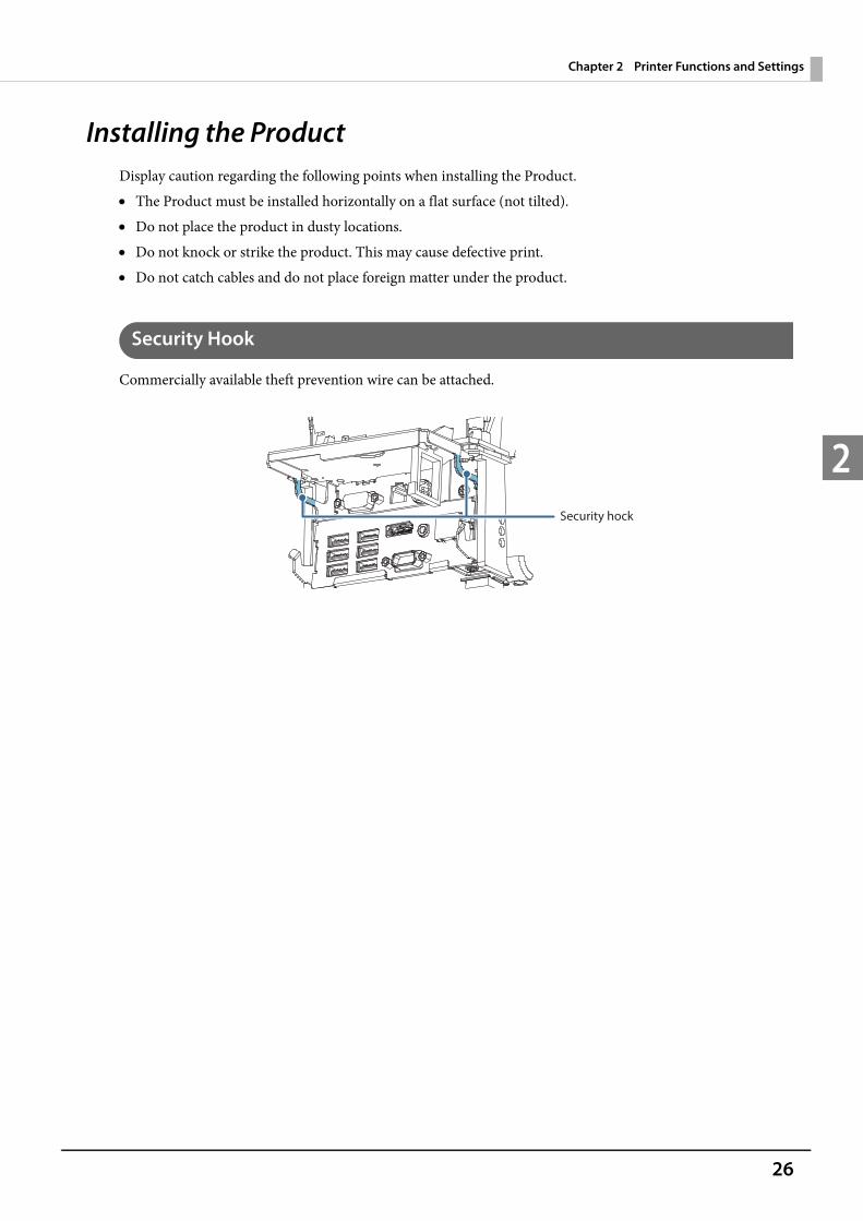
Security Hook
Commercially available theft prevention wire can be attached.
Security hock
27
Chapter 2 Printer Functions and Settings
2
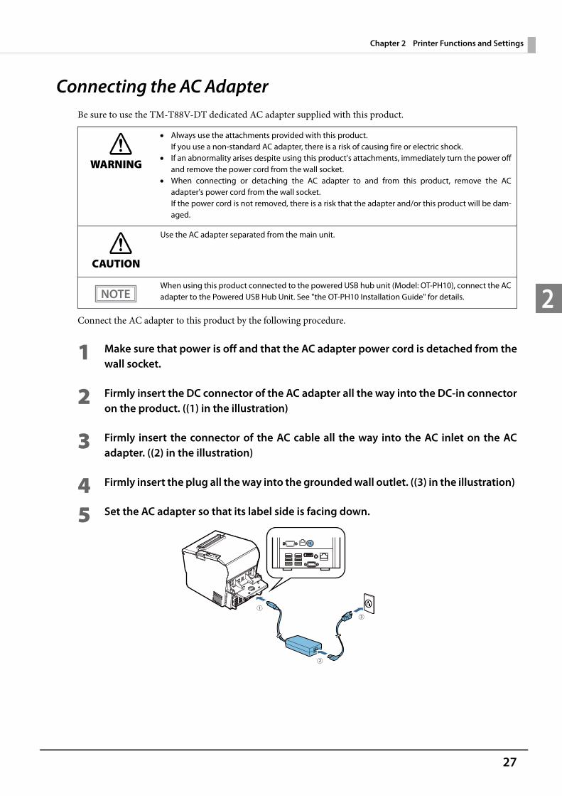
Connecting the AC AdapterBe sure to use the TM-T88V-DT dedicated AC adapter supplied with this product.
Connect the AC adapter to this product by the following procedure.
1 Make sure that power is off and that the AC adapter power cord is detached from the wall socket.
2 Firmly insert the DC connector of the AC adapter all the way into the DC-in connector on the product. ((1) in the illustration)
3 Firmly insert the connector of the AC cable all the way into the AC inlet on the AC adapter. ((2) in the illustration)
4 Firmly insert the plug all the way into the grounded wall outlet. ((3) in the illustration)
5 Set the AC adapter so that its label side is facing down.
WARNING
Always use the attachments provided with this product.If you use a non-standard AC adapter, there is a risk of causing fire or electric shock.
If an abnormality arises despite using this product's attachments, immediately turn the power off and remove the power cord from the wall socket.
When connecting or detaching the AC adapter to and from this product, remove the AC adapter's power cord from the wall socket. If the power cord is not removed, there is a risk that the adapter and/or this product will be dam-aged.
CAUTION
Use the AC adapter separated from the main unit.
When using this product connected to the powered USB hub unit (Model: OT-PH10), connect the AC adapter to the Powered USB Hub Unit. See "the OT-PH10 Installation Guide" for details.
28
Chapter 2 Printer Functions and Settings
2
Detaching the AC AdapterDetach the AC adapter from this product by the following procedure.
1 Make sure that power is off.
2 Detach the power cord from the wall socket.
3 Detach the AC adapter DC connector from this product.
29
Chapter 2 Printer Functions and Settings
2
Turning Power On and Off
Turning Power On
With product power turned off, press the power button. The power LED and the status LED (green) comes on.The status LED (orange) flashes during startup of the OS, when OS startup is finished, goes out.
Turning Power On for the First Time
When turning power on for the first time, it is necessary to perform Windows initial settings. For details, see "Windows Initial Settings" on page 63.
Turning Power Off
Turn this product power off by the following method. With this product power turned on, press the power button. Shutdown from Windows.
Do not turn power off by cutting the power breaker to which this product is connected.
Product power can also be turned off from EPSON TMNet WebConfig (page 117). Product power can also be turned off from the Web application. For details, see "ePOS-Device
SDK for JavaScript User's Manual".
30
Chapter 2 Printer Functions and Settings
2
Power Button Settings
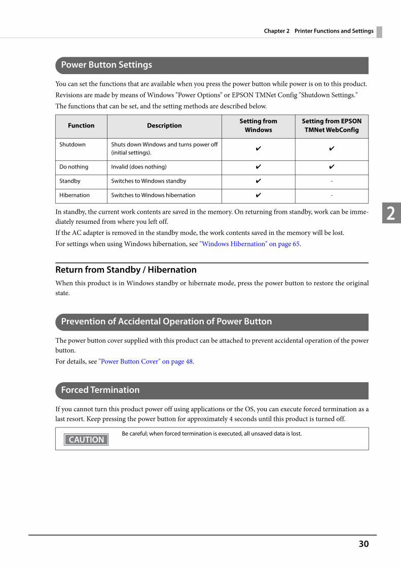
You can set the functions that are available when you press the power button while power is on to this product.Revisions are made by means of Windows "Power Options" or EPSON TMNet Config "Shutdown Settings." The functions that can be set, and the setting methods are described below.
In standby, the current work contents are saved in the memory. On returning from standby, work can be imme-diately resumed from where you left off.If the AC adapter is removed in the standby mode, the work contents saved in the memory will be lost.For settings when using Windows hibernation, see "Windows Hibernation" on page 65.
Return from Standby / HibernationWhen this product is in Windows standby or hibernate mode, press the power button to restore the original state.
Prevention of Accidental Operation of Power Button
The power button cover supplied with this product can be attached to prevent accidental operation of the power button. For details, see "Power Button Cover" on page 48.
Forced Termination
If you cannot turn this product power off using applications or the OS, you can execute forced termination as a last resort. Keep pressing the power button for approximately 4 seconds until this product is turned off.
Function DescriptionSetting from
Windows Setting from EPSON
TMNet WebConfig
Shutdown Shuts down Windows and turns power off (initial settings).
✔ ✔
Do nothing Invalid (does nothing) ✔ ✔
Standby Switches to Windows standby ✔ -
Hibernation Switches to Windows hibernation ✔ -
Be careful; when forced termination is executed, all unsaved data is lost.

31
Chapter 2 Printer Functions and Settings
2
Online and OfflineThis section describes the conditions in which the printer goes online and offline.This product's printer can print when it is online but not when it is offline.Because this product's computer and printer operate independently, the computer operates irrespective of the printer status.The printer LEDs display the following.
Online
This is the online status when no offline events or printer errors are happening.
Offline
The printer automatically goes offline under the following conditions: During power on (including resetting with the interface) until the printer is ready During the self-test When the roll paper cover is open While roll paper is feed using the Feed button When printing stops due to end of paper. (When the roll paper end sensor detects the end of paper or the
printer is set so that printing stops upon detection of roll paper near-end.) When an error has occurred (For detail, see "Error Status" on page 22.)
Printer Status Power LED Error LED
Online On Off
Offline On On
32
Chapter 2 Printer Functions and Settings
2
Handling the Roll Paper
Changing the Paper Width
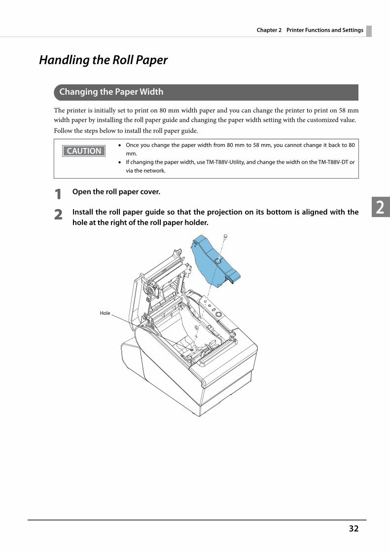
The printer is initially set to print on 80 mm width paper and you can change the printer to print on 58 mm width paper by installing the roll paper guide and changing the paper width setting with the customized value.Follow the steps below to install the roll paper guide.
1 Open the roll paper cover.
2 Install the roll paper guide so that the projection on its bottom is aligned with the hole at the right of the roll paper holder.
Once you change the paper width from 80 mm to 58 mm, you cannot change it back to 80 mm.
If changing the paper width, use TM-T88V-Utility, and change the width on the TM-T88V-DT or via the network.
Hole
33
Chapter 2 Printer Functions and Settings
2
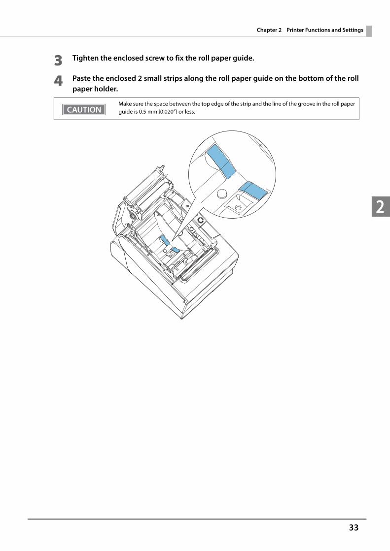
3 Tighten the enclosed screw to fix the roll paper guide.
4 Paste the enclosed 2 small strips along the roll paper guide on the bottom of the roll paper holder.
Make sure the space between the top edge of the strip and the line of the groove in the roll paper guide is 0.5 mm {0.020”} or less.
34
Chapter 2 Printer Functions and Settings
2
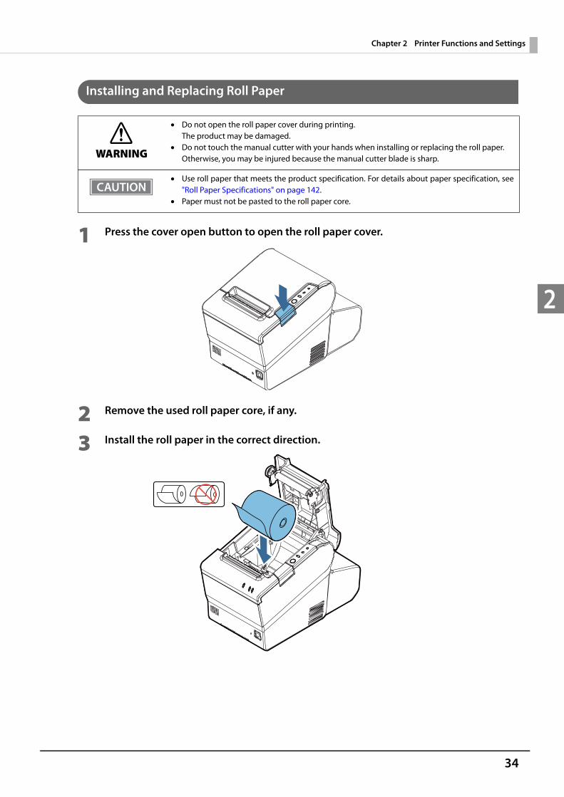
Installing and Replacing Roll Paper
1 Press the cover open button to open the roll paper cover.
2 Remove the used roll paper core, if any.
3 Install the roll paper in the correct direction.
WARNING
Do not open the roll paper cover during printing. The product may be damaged.
Do not touch the manual cutter with your hands when installing or replacing the roll paper.Otherwise, you may be injured because the manual cutter blade is sharp.
Use roll paper that meets the product specification. For details about paper specification, see "Roll Paper Specifications" on page 142.
Paper must not be pasted to the roll paper core.
35
Chapter 2 Printer Functions and Settings
2
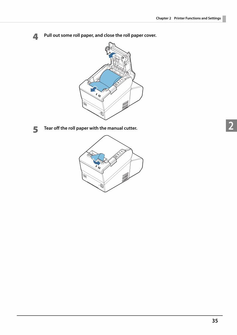
4 Pull out some roll paper, and close the roll paper cover.
5 Tear off the roll paper with the manual cutter.
36
Chapter 2 Printer Functions and Settings
2
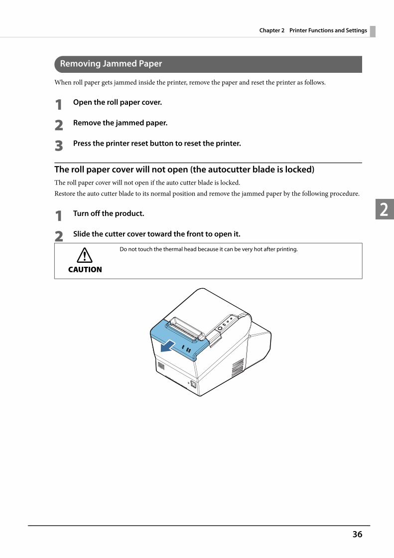
Removing Jammed Paper
When roll paper gets jammed inside the printer, remove the paper and reset the printer as follows.
1 Open the roll paper cover.
2 Remove the jammed paper.
3 Press the printer reset button to reset the printer.
The roll paper cover will not open (the autocutter blade is locked)The roll paper cover will not open if the auto cutter blade is locked.Restore the auto cutter blade to its normal position and remove the jammed paper by the following procedure.
1 Turn off the product.
2 Slide the cutter cover toward the front to open it.
CAUTION
Do not touch the thermal head because it can be very hot after printing.

37
Chapter 2 Printer Functions and Settings
2
3 Turn the knob until you see a triangle in the opening. This returns the cutter blade to the normal position.There is a label near the cutter to assist you.
4 Close the cutter cover.
5 Close the roll paper cover.
6 Remove the jammed paper.
7 Turn on the product.

38
Chapter 2 Printer Functions and Settings
2
Adjusting the Roll Paper Near-End
Below are two situations where a roll paper near-end sensor adjustment is required. To adjust the detection position to suit the diameter of the roll paper core used. To adjust the detection position of remaining amount of paper.
Follow the steps below to adjust the roll paper near-end sensor.
1 Open the roll paper cover, and remove the roll paper.
2 Loosen the adjustment screw fastening the sensor, and align the upper edge of the positioning plate with the adjustment position.
3 Tighten the adjustment screw.
4 After adjustment, make sure that the detection lever operates smoothly.
Since roll paper cores vary slightly in shape, depending on roll paper design and manufactur-ing tolerances, it is impossible to detect the remaining paper exactly.
Use roll paper with a core whose inner diameter is 12 mm {0.47"} and outer diameter is 18 mm {0.71"} so that the near-end sensor can detect the remaining paper as accurately as possible.
Adjustment positionRemaining amount of paper
(outer diameter: mm)
Upper Approx. 27 {1.06"}
Lower (Initial setting) Approx. 23 {0.97"}
Adjustment screw
Positioning plate
Detection lever
39
Chapter 2 Printer Functions and Settings
2
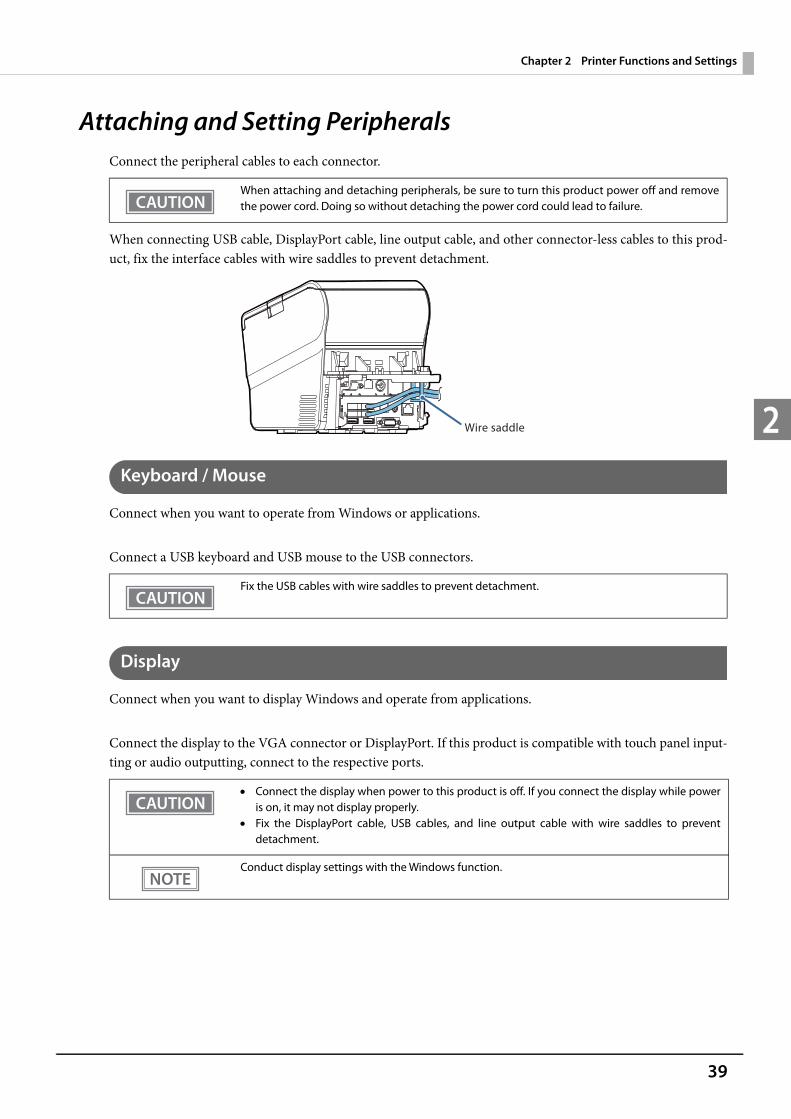
Attaching and Setting PeripheralsConnect the peripheral cables to each connector.
When connecting USB cable, DisplayPort cable, line output cable, and other connector-less cables to this prod-uct, fix the interface cables with wire saddles to prevent detachment.
Keyboard / Mouse
Connect when you want to operate from Windows or applications.
Connect a USB keyboard and USB mouse to the USB connectors.
Display
Connect when you want to display Windows and operate from applications.
Connect the display to the VGA connector or DisplayPort. If this product is compatible with touch panel input-ting or audio outputting, connect to the respective ports.
When attaching and detaching peripherals, be sure to turn this product power off and remove the power cord. Doing so without detaching the power cord could lead to failure.
Fix the USB cables with wire saddles to prevent detachment.
Connect the display when power to this product is off. If you connect the display while power is on, it may not display properly.
Fix the DisplayPort cable, USB cables, and line output cable with wire saddles to prevent detachment.
Conduct display settings with the Windows function.
Wire saddle
40
Chapter 2 Printer Functions and Settings
2
USB Printer
Connect the USB printer to a USB connector. For printer settings, see the "Technical Reference Guide" of each TM printer. PC-POS System
Set the driver, etc. according to each system of use. For details, see "PC-POS System Development" on page 128.
Systems that use TM-DT software cannot be used.
Network Printer
Network printers are connected to the same network as this product. For printer settings, see the "Technical Reference Guide" of each TM printer. PC-POS System
Set the driver, etc. according to each system of use. For details, see "PC-POS System Development" on page 128.
Systems that use TM-DT softwareSet the device ID, IP address, printer model, and other settings with EPSON TMNet WebConfig. For details, see "Settings - Web service settings - Printer" on page 102.
Customer Display
Connect the customer display (optional) to a USB connector.For how to connect the customer display and make dip switch settings, etc., see "DM-D110 Technical Reference Guide". PC-POS System
This product is installed with a customer display COM-USB conversion driver, so it is recognized as a virtual COM port.Set the driver, etc. according to each system of use. For details, see "PC-POS System Development" on page 128.
Systems that use TM-DT softwareSet whether or not to use the customer display, communication speed and so on with EPSON TMNet Web-Config. For details, see "Settings - Web service settings - Customer Display" on page 103.
Fix the USB cables with wire saddles to prevent detachment.
Fix the USB cables with wire saddles to prevent detachment.

41
Chapter 2 Printer Functions and Settings
2
OperationWhen changing the direction and angle of the customer display, move the display section and L-shaped support while holding this product down by hand. When the movement stops, do not move it any more.
The mobile range of the display is as follows. Display tilt: Maximum angle of 48° (5 levels)
Display rotation: Maximum angle of 300°
Arm rotation: Maximum angle of 270°
CAUTION
Do not rotate the display with excessive force. Doing so may break it.
48°
300°
270°
42
Chapter 2 Printer Functions and Settings
2
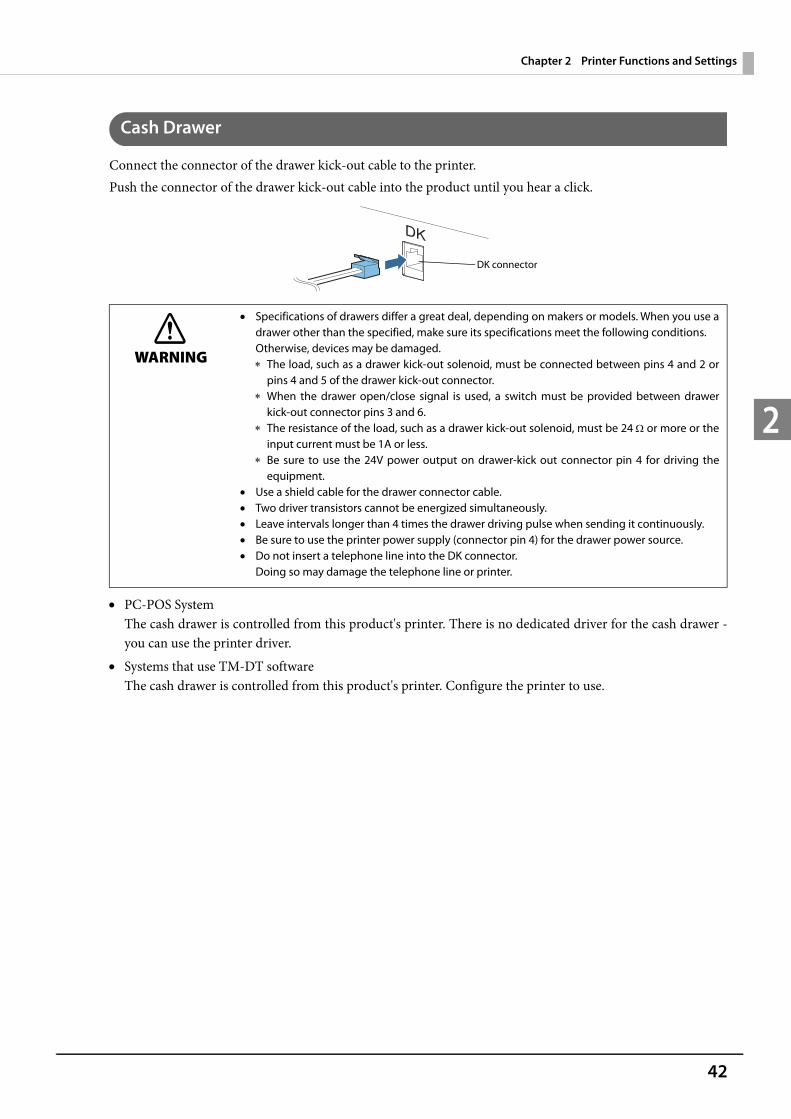
Cash Drawer
Connect the connector of the drawer kick-out cable to the printer.Push the connector of the drawer kick-out cable into the product until you hear a click.
PC-POS SystemThe cash drawer is controlled from this product's printer. There is no dedicated driver for the cash drawer - you can use the printer driver.
Systems that use TM-DT softwareThe cash drawer is controlled from this product's printer. Configure the printer to use.
WARNING
Specifications of drawers differ a great deal, depending on makers or models. When you use a drawer other than the specified, make sure its specifications meet the following conditions.Otherwise, devices may be damaged. The load, such as a drawer kick-out solenoid, must be connected between pins 4 and 2 or
pins 4 and 5 of the drawer kick-out connector. When the drawer open/close signal is used, a switch must be provided between drawer
kick-out connector pins 3 and 6. The resistance of the load, such as a drawer kick-out solenoid, must be 24 or more or the
input current must be 1A or less. Be sure to use the 24V power output on drawer-kick out connector pin 4 for driving the
equipment. Use a shield cable for the drawer connector cable. Two driver transistors cannot be energized simultaneously. Leave intervals longer than 4 times the drawer driving pulse when sending it continuously. Be sure to use the printer power supply (connector pin 4) for the drawer power source. Do not insert a telephone line into the DK connector.
Doing so may damage the telephone line or printer.
DK connector
43
Chapter 2 Printer Functions and Settings
2
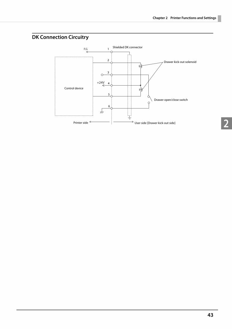
DK Connection Circuitry
F.G
+24V
Shielded DK connector
Printer side User side [Drawer kick-out side]
Drawer open/close switch
Drawer kick-out solenoid
Control device
1
2
3
4
5
6
44
Chapter 2 Printer Functions and Settings
2
Key Input Device
Connect the key input device to a USB connector. For how to set barcode scanners and so on, see the respective product manuals. PC-POS System
Since it is recognized as a HID device, setting is not required. Systems that use TM-DT software
Set the device ID, control script and so on with EPSON TMNet WebConfig. For details, see "Settings - Web service settings - Key input device" on page 104.
Serial Communication Device
Connect the serial communication device to a COM connector. For how to set the device, install the driver and so on, see the respective product manuals. PC-POS System
Align communication conditions between this product and the device. Systems that use TM-DT software
Align communication conditions between EPSON TMNet WebConfig and the device.Set the device ID, communication conditions, control script and so on with EPSON TMNet WebConfig. For details, see "Settings - Web Service settings - Serial communication Device" on page 105.
Powered USB Hub Unit
Attach the powered USB hub unit to the base of this product, and connect the cables to this product's DC con-nector and USB connector. For details on the powered USB hub unit, see "OT-PH10 Installation Guide".
Fix the USB cables with wire saddles to prevent detachment.

45
Chapter 2 Printer Functions and Settings
2
Network Settings
Connect to Wired LAN
LAN Cable Connections
Push the 10BASE-T/100BASE-TX LAN cable into the LAN connector until you hear a click.
Network SettingsSet the IP address and other network settings. Settings can be made as follows. Setting on Windows
Perform the same settings as with the Windows PC. Setting on EPSON TMNet WebConfig (page 112)
CAUTION
When LAN cables are installed outdoors, make sure devices without proper surge protection are cushioned by being connected through devices that do have surge protection. Otherwise, the devices can be damaged by lightning.
Never attempt to connect the customer display cable, drawer kick-out cable, or a telephone line cable to the Ethernet connector.
46
Chapter 2 Printer Functions and Settings
2
Connect to Wireless LAN
You can use the optional wireless LAN cable set (OT-WL01) to connect this product to a wireless LAN.
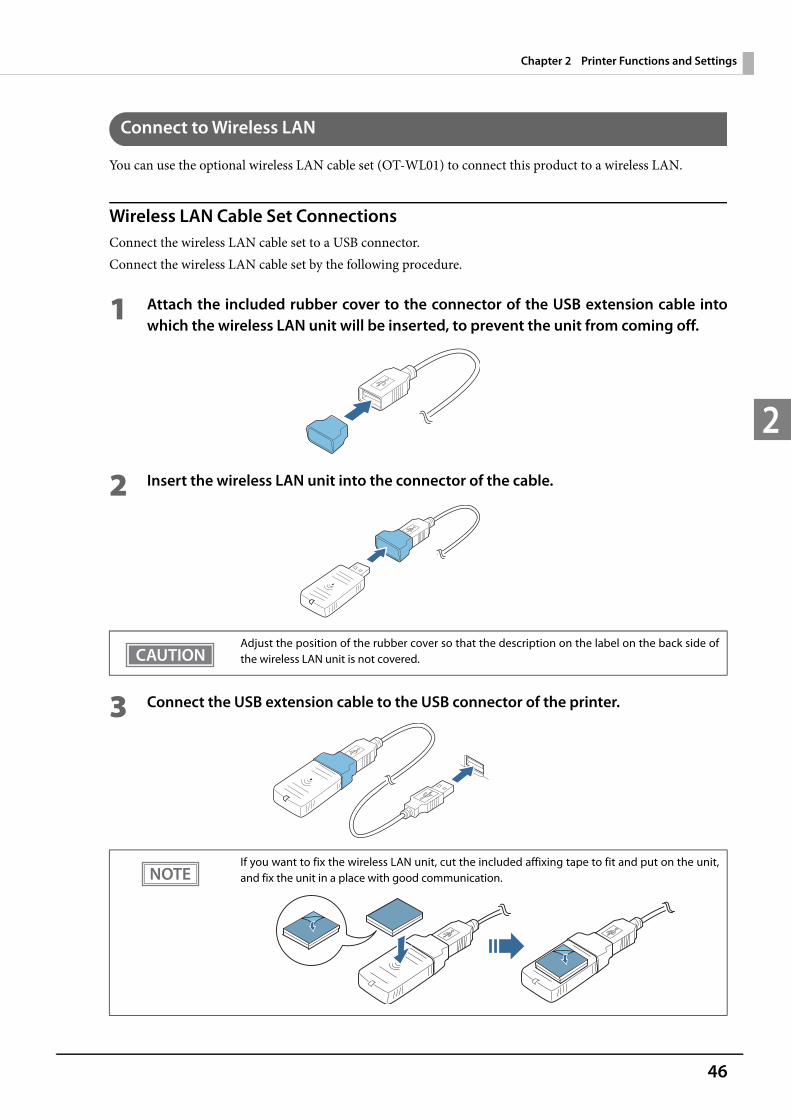
Wireless LAN Cable Set ConnectionsConnect the wireless LAN cable set to a USB connector.Connect the wireless LAN cable set by the following procedure.
1 Attach the included rubber cover to the connector of the USB extension cable into which the wireless LAN unit will be inserted, to prevent the unit from coming off.
2 Insert the wireless LAN unit into the connector of the cable.
3 Connect the USB extension cable to the USB connector of the printer.
Adjust the position of the rubber cover so that the description on the label on the back side of the wireless LAN unit is not covered.
If you want to fix the wireless LAN unit, cut the included affixing tape to fit and put on the unit, and fix the unit in a place with good communication.
47
Chapter 2 Printer Functions and Settings
2
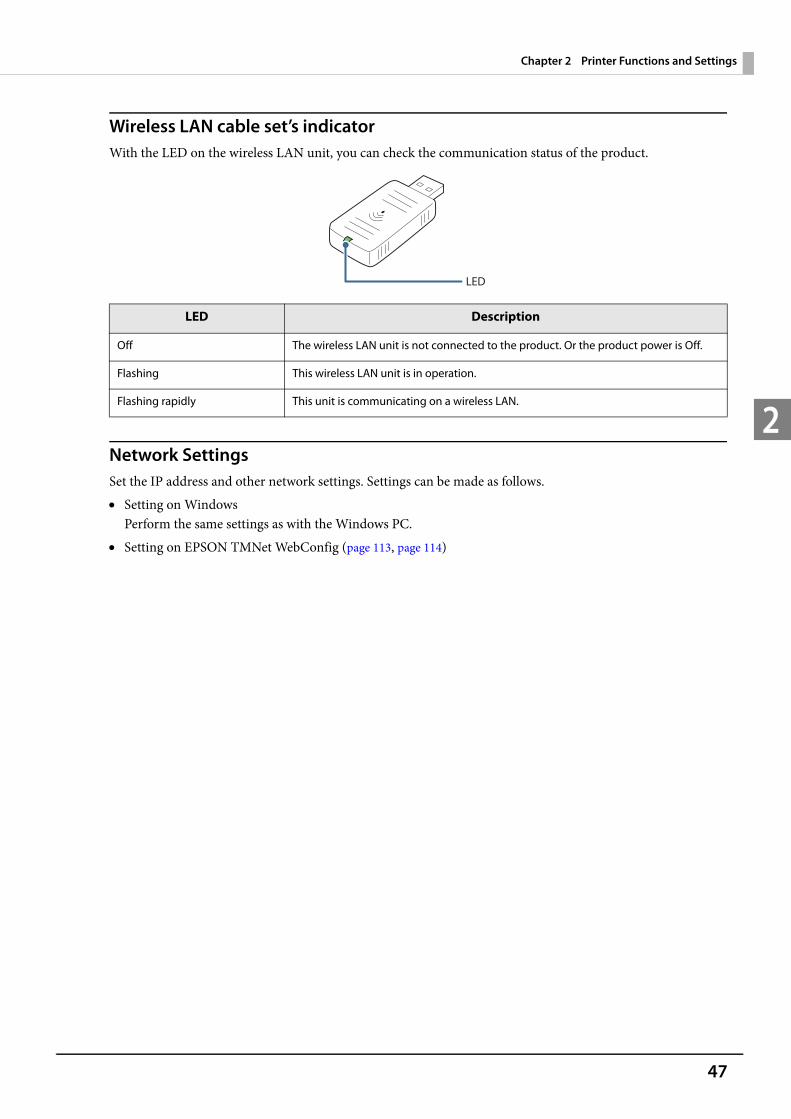
Wireless LAN cable set’s indicatorWith the LED on the wireless LAN unit, you can check the communication status of the product.
Network SettingsSet the IP address and other network settings. Settings can be made as follows. Setting on Windows
Perform the same settings as with the Windows PC. Setting on EPSON TMNet WebConfig (page 113, page 114)
LED Description
Off The wireless LAN unit is not connected to the product. Or the product power is Off.
Flashing This wireless LAN unit is in operation.
Flashing rapidly This unit is communicating on a wireless LAN.
LED

48
Chapter 2 Printer Functions and Settings
2
Attaching Accessories
Power Button Cover
The power button cover supplied with this product can be attached to prevent accidental operation of the power button.
1 Open the power button cover.
2 Peel off the backing paper.
3 Attach the power button cover as shown in the illustration.
If the area around the power button is dirty, Epson recommends wiping clean before attaching the cover.
Align the inside edge of the power button cover with the upper edge of the power button. Align the left edge of the power button cover
with the right edge of the printer reset button.
Printer reset button Power button
49
Chapter 2 Printer Functions and Settings
2
Connector Cover
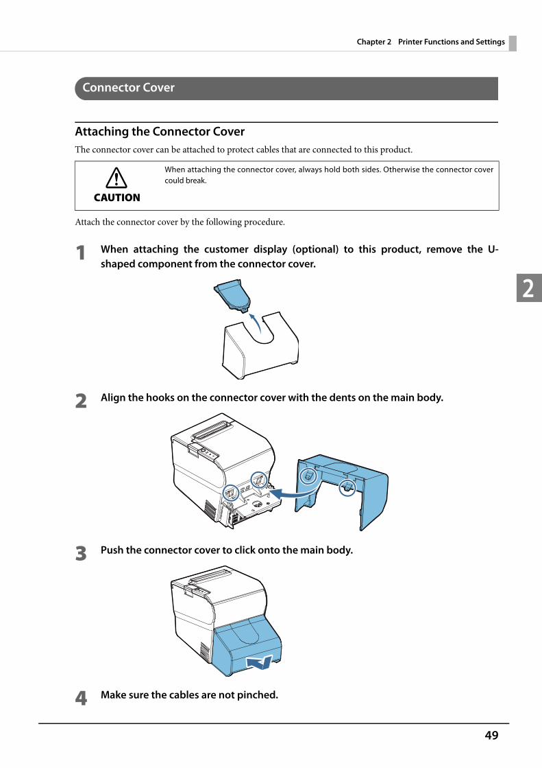
Attaching the Connector CoverThe connector cover can be attached to protect cables that are connected to this product.
Attach the connector cover by the following procedure.
1 When attaching the customer display (optional) to this product, remove the U-shaped component from the connector cover.
2 Align the hooks on the connector cover with the dents on the main body.
3 Push the connector cover to click onto the main body.
4 Make sure the cables are not pinched.
CAUTION
When attaching the connector cover, always hold both sides. Otherwise the connector cover could break.
50
Chapter 2 Printer Functions and Settings
2
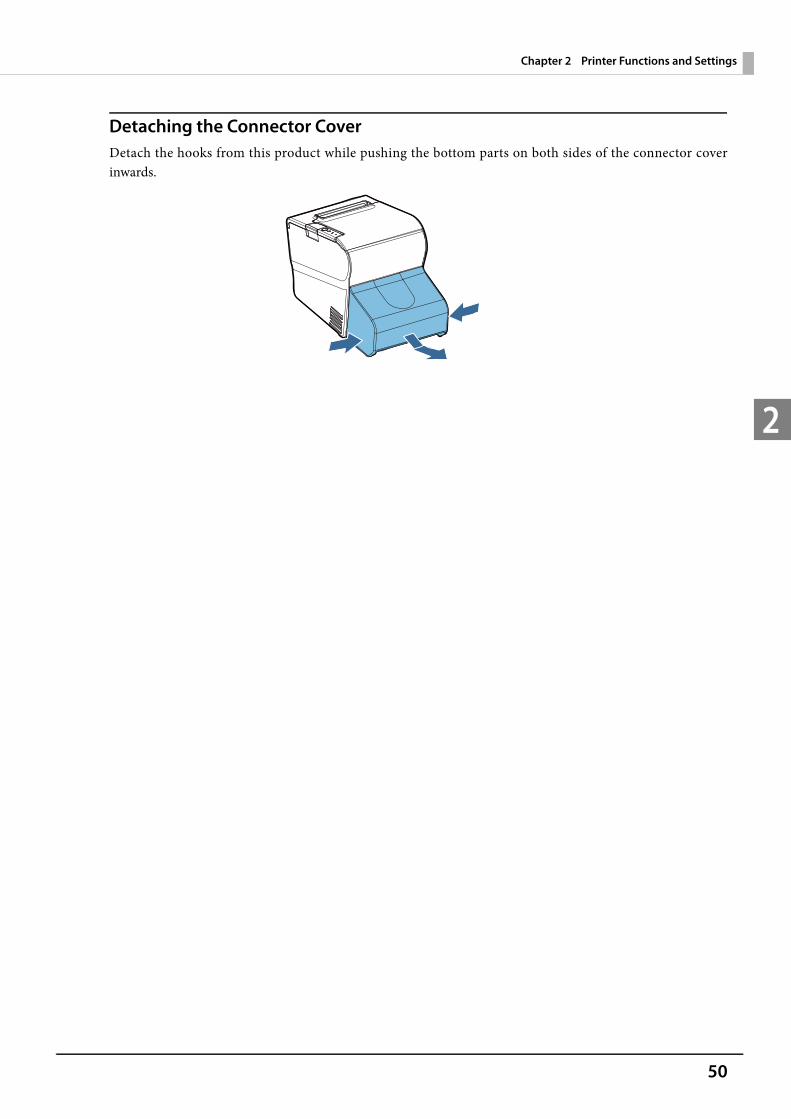
Detaching the Connector CoverDetach the hooks from this product while pushing the bottom parts on both sides of the connector cover inwards.

51
Chapter 2 Printer Functions and Settings
2
Affixing Tape (Optional)
When fixing this product onto a mounting surface using the optional affixing tape (model number: DF-10), fol-low the procedure below.
1 Turn over the product so that you can see its bottom.
2 With two pieces of the affixing tape combined, peel off the backing paper of a pair on one side, and paste it to one of the specified positions on the bottom of the product.
3 In the same way, paste other three pairs of tape in the specified positions.
4 Peel off the backing paper of each pair on the other side of the affixing tape, turn over the product back on its bottom, and place and secure it firmly to the installation surface.
Positioning lines
52
Chapter 2 Printer Functions and Settings
2
Cleaning
Thermal Head
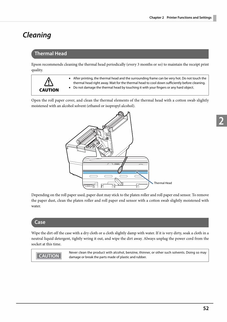
Epson recommends cleaning the thermal head periodically (every 3 months or so) to maintain the receipt print quality.
Open the roll paper cover, and clean the thermal elements of the thermal head with a cotton swab slightly moistened with an alcohol solvent (ethanol or isopropyl alcohol).
Depending on the roll paper used, paper dust may stick to the platen roller and roll paper end sensor. To remove the paper dust, clean the platen roller and roll paper end sensor with a cotton swab slightly moistened with water.
Case
Wipe the dirt off the case with a dry cloth or a cloth slightly damp with water. If it is very dirty, soak a cloth in a neutral liquid detergent, tightly wring it out, and wipe the dirt away. Always unplug the power cord from the socket at this time.
CAUTION
After printing, the thermal head and the surrounding frame can be very hot. Do not touch the thermal head right away. Wait for the thermal head to cool down sufficiently before cleaning.
Do not damage the thermal head by touching it with your fingers or any hard object.
Never clean the product with alcohol, benzine, thinner, or other such solvents. Doing so may damage or break the parts made of plastic and rubber.
Thermal Head

53
Chapter 2 Printer Functions and Settings
2
Preparing for TransportFollow the steps below to transport the product.
1 Turn off the product.
2 Remove the peripherals and the AC adapter.
3 Remove the roll paper.
4 Pack this product upright.

54
Chapter 2 Printer Functions and Settings
2
Setting the Memory SwitchesThis product contains memory switches (customized value). The memory switch settings determine the opera-tions of the built-in printer.To change the memory switch settings, use the software setting mode or the TM-T88V Utility. The settings that can be changed with each of these are shown below.
Function Software Setting Mode TM-T88V Utility
Paper width - -
Print density ✔ ✔
Multi-tone print density ✔ ✔
Print speed ✔ ✔
FontCode pageInternational character setFont A/B replacement
✔ ✔
Optional Buzzer - -
Number of head energizing parts ✔ -
Power supply unit capacity ✔ ✔
Automatic paper cut ✔ ✔
Paper reductionUpper space reductionLower space reductionLine space reduction rateLine feed reduction rateBarcode height reduction rate
✔ ✔
Concerning TM-T88V Utility, see the User's Manual included in TM-T88V Utility. To directly configure the product in the software setting mode, see "Software Setting Mode"
on page 61.
55
Chapter 2 Printer Functions and Settings
2
Functions
Paper widthBe sure to install the roll paper guide when you select the 58 mm paper width. 80 mm (initial setting) 58 mm
Print densitySelectable from “Depends On Dip Switch”, or levels 1 to 13 (70% ~ 130%)
Multiple tone densitySelectable from levels 1 to 13 (70% ~ 130%) (initial setting: level 7)
Print speedSelectable from levels 1 to 13 (Slow ~ Fast) (initial setting: level 13)
Font Code page: Selectable from 43 pages International character set: Selectable from 18 sets Font A/B replacement
External optional buzzer settings
Once you change the paper width from 80 mm to 58 mm, you cannot change it back to 80 mm.
When the print density setting is configured to "Depends On Dip Switch" (default setting), the print density will be standard. Use in this setting at normal times. Other settings can also be con-figured.
First change the print density, and then configure the multiple tone print density. If you set the density too high, the contrast becomes lower. Select the density level checking
the overall tone balance of your image.
Depending on print conditions, such as print duty and print head temperature, print speed is automatically adjusted, which may cause white lines due to intermittent print (the motor some-times stops). To avoid this, keep the print speed constant by setting it lower.
Not used with this product.
56
Chapter 2 Printer Functions and Settings
2
Setting the number of head energizing parts One-part energizing (initial setting) Two-part energizing Four-part energizing
Power Supply unit capacitySelectable from levels 1 to 3 (Low High) (initial setting: level 3) When a problem such as a low voltage error and power shutdown occurs due to the print pattern or the power supply environment, you might work around the problem by setting the power supply unit capacity.If you cannot solve the problem by setting the power supply unit capacity to "level 1", you can try reducing the print speed, increasing the number of head energizing parts, or revising the print pattern (reducing the print volume).
Automatic paper cut Not use this function (initial setting) Cut paper when the cover is closed Print logo when paper is cut
Setting the paper reductionThe paper feed (margin) part and bar code included in the print data can be reduced. Extra upper space reduction Extra lower space reduction Line space reduction rate Line feed reduction rate Barcode height reduction rate
Usually, the number of head energizing parts does not need to be changed. The maximum print speed (300 m/s {11.81”/s}) can be performed only when one-part energiz-
ing is selected.
“Printing logo when paper is cut” is not available with software setting mode.
57
Chapter 2 Printer Functions and Settings
2
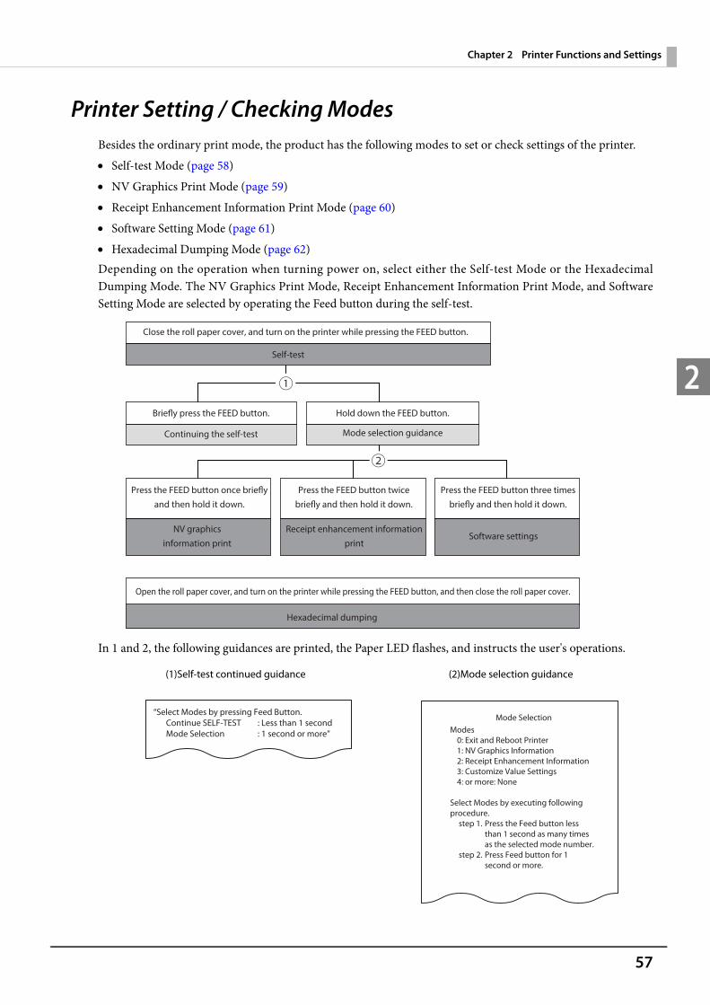
Printer Setting / Checking ModesBesides the ordinary print mode, the product has the following modes to set or check settings of the printer. Self-test Mode (page 58) NV Graphics Print Mode (page 59) Receipt Enhancement Information Print Mode (page 60) Software Setting Mode (page 61) Hexadecimal Dumping Mode (page 62)Depending on the operation when turning power on, select either the Self-test Mode or the Hexadecimal Dumping Mode. The NV Graphics Print Mode, Receipt Enhancement Information Print Mode, and Software Setting Mode are selected by operating the Feed button during the self-test.
In 1 and 2, the following guidances are printed, the Paper LED flashes, and instructs the user's operations.
(1)Self-test continued guidance (2)Mode selection guidance
Close the roll paper cover, and turn on the printer while pressing the FEED button.
Self-test
Briefly press the FEED button. Hold down the FEED button.
Press the FEED button once briefly and then hold it down.
Open the roll paper cover, and turn on the printer while pressing the FEED button, and then close the roll paper cover.
Continuing the self-test Mode selection guidance
NV graphicsinformation print
Receipt enhancement information print
Software settings
Hexadecimal dumping
Press the FEED button twice briefly and then hold it down.
Press the FEED button three times briefly and then hold it down.
“Select Modes by pressing Feed Button.
Continue SELF-TEST : Less than 1 second
Mode Selection : 1 second or more”
Mode Selection
Modes
0: Exit and Reboot Printer
1: NV Graphics Information
2: Receipt Enhancement Information
3: Customize Value Settings
4: or more: None
Select Modes by executing following
procedure.
step 1. Press the Feed button less
than 1 second as many times
as the selected mode number.
step 2. Press Feed button for 1
second or more.
58
Chapter 2 Printer Functions and Settings
2
Self-test mode
You can confirm the following information by running the self-test mode. Printer firmware version Receive buffer size BUSY conditions Built-in character sets Print density Maintenance Information (Print head running length, count of auto-cutting)
Follow the steps below.
1 Close the roll paper cover.
2 While pressing the Feed button, turn on the printer. (Keep pressing the Feed button until the printer starts printing.)After the printer status is printed, the self-test printing continuance guidance is printed and Paper LED flashes.
3 Press the Feed button for less than 1 second to continue the self-test.Built-in characters are printed with rolling printing.After printing "*** completed ***", the printer is initialized and enters the normal mode.
59
Chapter 2 Printer Functions and Settings
2
NV Graphics Information Print Mode
You can confirm the following information by running NV graphics print mode. Capacity of the NV graphics Used amount of the NV graphics Unused capacity of the NV graphics Number of NV graphics that are registered Key code, number of dots in X direction, number of dots in Y direction, number of colors to be defined. NV graphics data
Follow the steps below.
1 After implementing the self-test, press the Feed button for an extended period (1 second or more) to select the mode.The mode selection guidance is printed, and the paper LED flashes.
2 After pressing the Feed button for a short period (less than 1 second), press it for an extended period (1 second or more) to print the NV graphics information.After the NV graphics information is printed, the mode selection guidance will be printed again.
3 In order to finish, either turn power off or select "Exit and Reboot Printer."
60
Chapter 2 Printer Functions and Settings
2
Receipt Enhancement Information Print Mode
You can confirm the following information by running the receipt enhancement information mode. Automatic top logo setting Automatic bottom logo setting Extended settings for automatic top/bottom logo
Follow the steps below.
1 After implementing the self-test, press the Feed button for an extended period (1 second or more) to select the mode.The mode selection guidance is printed, and the paper LED flashes.
2 After pressing the Feed button twice (less than 1 second), press it for an extended period (1 second or more) to print the NV graphics information.After the receipt enhancement information is printed, the mode selection guidance will be printed again.
3 In order to finish, either turn power off or select "Exit and Reboot Printer."
61
Chapter 2 Printer Functions and Settings
2
Software Setting Mode
In the software setting mode, configure the printer memory switches. See "Functions" on page 55 for the setting items. Receipt print density Paper reduction Autocutting at roll paper cover close Printing width Character code page / International Character set Embedded font replacement Power supply output Print speed Other settings
Follow the steps below.
1 After implementing the self-test, press the Feed button for an extended period (1 second or more) to select the mode.The mode selection guidance is printed, and the paper LED flashes.
2 After pressing the Feed button for three times(less than 1 second), press it for an extended period (1 second or more) to print the NV graphics information.The Software setting mode guidance is printed.
3 After pressing the Feed button for a short time (less than 1 second) for the number of times indicated in the printing results, press it for an extended period (1 second or more) to select the setting item.
4 After pressing the Feed button for a short time (less than 1 second) for the number of times indicated in the printing results, press it for an extended period (1 second or more) to select the setting value. The customized value will be saved, and the items that can be set in the software setting mode will be printed again.
5 In order to finish, either turn power off or select "Exit and Reboot Printer."
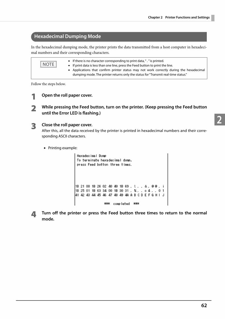
62
Chapter 2 Printer Functions and Settings
2
Hexadecimal Dumping Mode
In the hexadecimal dumping mode, the printer prints the data transmitted from a host computer in hexadeci-mal numbers and their corresponding characters.
Follow the steps below.
1 Open the roll paper cover.
2 While pressing the Feed button, turn on the printer. (Keep pressing the Feed button until the Error LED is flashing.)
3 Close the roll paper cover.After this, all the data received by the printer is printed in hexadecimal numbers and their corre-sponding ASCII characters.
Printing example:
4 Turn off the printer or press the Feed button three times to return to the normal mode.
If there is no character corresponding to print data, “ . ” is printed. If print data is less than one line, press the Feed button to print the line. Applications that confirm printer status may not work correctly during the hexadecimal
dumping mode. The printer returns only the status for “Transmit real-time status.”

63
Chapter 3 Windows Settings
3
Windows SettingsWindows Embedded POSReady 7
Windows Initial Settings
The following explains the procedures for the Windows initial settings when you turn on the power for this product for the first time.
1 Making sure that this product power is off, connect the display and keyboard.
2 Turn on the product.The Windows setup screen is displayed.
3 When the log-on screen appears, enter the password. For the initial settings, the user name is "EPSON-USER" and the password is "T88V-DT".
4 The Windows desktop is displayed. Select [Start], then [Control Panel], and [Date and Time]. The "Date and Time Properties" window is displayed. Set the date, time, and the time zone.
Starting Up and Shutting Down Windows
Starting Up Windows Windows starts up when power to this product is turned on.
Shutting Down WindowsPower to this product is turned off when Windows is shut down.
Date, time, and time zone can be set later.

64
Chapter 3 Windows Settings
3
Enabling or Disabling ePOS-Device
On this product, TM-DT software operates on Windows. If using this product with the PC-POS system or Thin-Client system, do not use this software. If operation of this software is disabled, the useable memory can be increased by 100MB or more.
Enabling ePOS-Device ServiceRun [ePOS-Device Enabled] from the shortcut on the desktop.
Disabling ePOS-Device ServiceRun [ePOS-Device Disabled] from the shortcut on the desktop.
Speaker Volume Setting
Volume of the speakers equipped in this product can be adjusted using the speaker volume adjustment function in Windows.
ePOS-Device Service is set to [Enabled] in the default settings.
65
Chapter 3 Windows Settings
3
Windows Hibernation
Windows can be entered into hibernate mode by pressing the power button of this product.During hibernation, the current work contents are saved. On returning from hibernation, work can be resumed from the previous state.Since Windows hibernation cannot be used in the initial settings, configure according to necessity.
1 Making sure that this product power is off, connect the display and keyboard.
2 Turn this product's power on and immediately press "Delete" key on the keyboard for a prolonged time to start up the BIOS menu.
3 Operating the keyboard direction keys, select "Advanced" tab and "ACPI Settings".
4 Press "Enter" key on the keyboard. The "ACPI Settings" sub-menu is displayed.
5 Operating the keyboard direction keys, select "Enable ACPI Configuration" and press "Enter" key.
6 Select "Enabled" and press "Enter" key."Enable ACPI Auto Configuration" is set to "Enabled".
7 Press "Esc" key on the keyboard to close the "ACPI Settings" sub-menu.
8 Operating the keyboard direction keys, select "Save & Exit" tab and "Save Changes and Reset".
9 Press "Enter" key on the keyboard to display the confirmation message.Select "Yes" and press "Enter" key.The BIOS settings are saved and Windows is started.
10The log-on screen is displayed. Log on to Windows.The Windows desktop screen is displayed.
This setting is effective in Windows Embedded POSReady 7. Conduct this setting with a user account that has administrator authority. When you use Windows hibernation, a system file with the same capacity as the main memory
is created.
For how to connect peripherals, see "Attaching and Setting Peripherals" on page 39.

66
Chapter 3 Windows Settings
3
11From [Start]-[All Programs]-[Accessories], right-click "Command Prompt" and click "Execute as Administrator".
12The "User Account Control" screen is displayed. Click [Yes].
13Execute the following commands.powercfg /h on
It becomes possible to select Windows hibernation in the Windows power options.
67
Chapter 3 Windows Settings
3
Windows Recovery
Follow the steps below to perform the recovery and Windows initial setting.
1 Making sure that this product power is off, connect the display, keyboard, mouse, and DVD drive.
2 Insert the recovery disk into the DVD drive.
3 Turn on the product, and "Press any key to boot from CD or DVD" is displayed. Press any key.
4 The system starts using the recovery disk. When a message that says "Do you want to recover?" is displayed. Click [Yes].
5 A confirmation message that says "All data on disc will be deleted. Do you really want to start recovery?" is displayed. Click [Yes].Recovery is performed.
6 After the recovery procedure, the system automatically shuts down. The system automatically restarts several times for Windows initialization.
7 When the log-on screen is displayed, enter the password.The initial user name is “EPSON-USER”, and the initial password is "T88V-DT".
8 Select [Start]-[Control Panel]-[Date and Time], and the [Date and Time menu] is dis-played. Set the date, time, and time zone.
9 Turn off the product. Then remove the display, keyboard, mouse, and DVD drive.
This brings the recovery and Windows initial settings to an end.
When the recovery procedure is performed, all data will be deleted. Back up any necessary data before performing the procedure.
Recovery requires about 30 minutes. A DVD drive with USB interface is required in order to perform Windows recovery.
For how to connect peripherals, see "Attaching and Setting Peripherals" on page 39.
Do not enter any information until the Windows log-in screen appears.
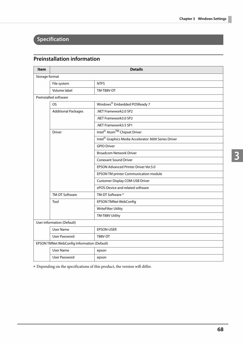
68
Chapter 3 Windows Settings
3
Specification
Preinstallation information
Depending on the specifications of this product, the version will differ.
Item Details
Storage format
File system NTFS
Volume label TM-T88V-DT
Preinstalled software
OS Windows Embedded POSReady 7
Additional Packages .NET Framework2.0 SP2
.NET Framework3.0 SP2
.NET Framework3.5 SP1
Driver IntelAtomTM Chipset Driver
Intel Graphics Media Accelerator 3600 Series Driver
GPIO Driver
Broadcom Network Driver
Conexant Sound Driver
EPSON Advanced Printer Driver Ver.5.0
EPSON TM printer Communication module
Customer Display COM-USB Driver
ePOS-Device and related software
TM-DT Software TM-DT Software *
Tool EPSON TMNet WebConfig
WriteFilter Utility
TM-T88V Utility
User information (Default)
User Name EPSON-USER
User Password T88V-DT
EPSON TMNet WebConfig Information (Default)
User Name epson
User Password epson
69
Chapter 3 Windows Settings
3
Windows Embedded POSReady 2009
Windows Initial Settings
The following explains the procedures for the Windows initial settings when you turn on the power for this product for the first time.
1 Making sure that this product power is off, connect the display and keyboard.
2 Turn on the product.The Windows setup screen is displayed.
3 When the log-on screen appears, enter the password. For the initial settings, the user name is "EPSON-USER" and the password is "T88V-DT".
4 The Windows desktop is displayed. Select [Start], then [Control Panel], and [Date and Time]. The "Date and Time Properties" window is displayed. Set the date, time, and the time zone.
Starting Up and Shutting Down Windows
Starting Up Windows Windows starts up when power to this product is turned on.
Shutting Down WindowsPower to this product is turned off when Windows is shut down.
Date, time, and time zone can be set later.
70
Chapter 3 Windows Settings
3
Enabling or Disabling ePOS-Device
On this product, TM-DT software operates on Windows. If using this product with the PC-POS system or Thin-Client system, do not use this software. If operation of this software is disabled, the useable memory can be increased by 100MB or more.
Enabling ePOS-Device ServiceRun [ePOS-Device Enabled] from the shortcut on the desktop.
Disabling ePOS-Device ServiceRun [ePOS-Device Disabled] from the shortcut on the desktop.
Speaker Volume Setting
Volume of the speakers equipped in this product can be adjusted using the speaker volume adjustment function in Windows.
ePOS-Device Service is set to [Enabled] in the default settings.
71
Chapter 3 Windows Settings
3
Windows Recovery
Follow the steps below to perform the recovery and Windows initial setting.
1 Making sure that this product power is off, connect the display, keyboard, mouse, and DVD drive.
2 Insert the recovery disk into the DVD drive.
3 Turn on the product, and "Press any key to boot from CD or DVD" is displayed. Press any key.
4 The system starts using the recovery disk. When a message that says "Do you want to recover?" is displayed. Click [Yes].
5 A confirmation message that says "All data on disc will be deleted. Do you really want to start recovery?" is displayed. Click [Yes].Recovery is performed.
6 After the recovery procedure, the system automatically shuts down. The system automatically restarts several times for Windows initialization.
7 When the log-on screen is displayed, enter the password.The initial user name is “EPSON-USER”, and the initial password is "T88V-DT".
8 Select [Start]-[Control Panel]-[Date and Time], and the [Date and Time menu] is dis-played. Set the date, time, and time zone.
9 Turn off the product. Then remove the display, keyboard, mouse, and DVD drive.
When the recovery procedure is performed, all data will be deleted. Back up any necessary data before performing the procedure.
Recovery requires about 40 minutes. A DVD drive with USB interface is required in order to perform Windows recovery.
For how to connect peripherals, see "Attaching and Setting Peripherals" on page 39.
Do not enter any information until the Windows log-in screen appears.
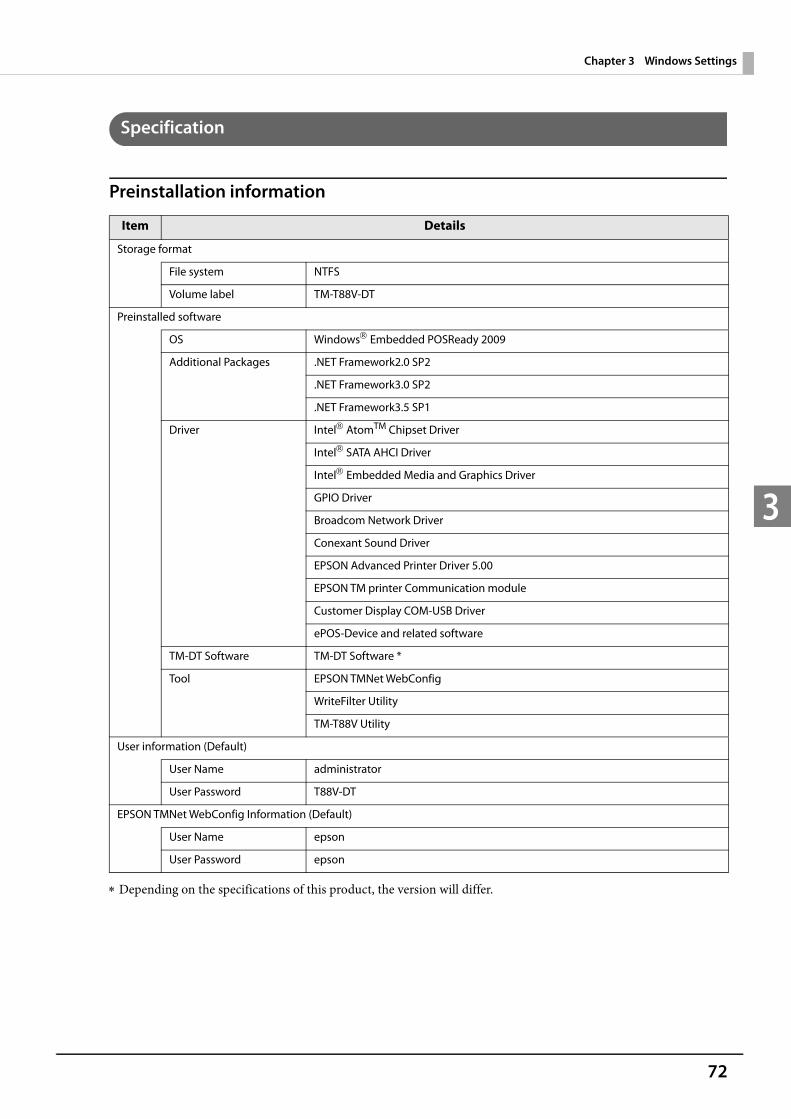
72
Chapter 3 Windows Settings
3
Specification
Preinstallation information
Depending on the specifications of this product, the version will differ.
Item Details
Storage format
File system NTFS
Volume label TM-T88V-DT
Preinstalled software
OS Windows Embedded POSReady 2009
Additional Packages .NET Framework2.0 SP2
.NET Framework3.0 SP2
.NET Framework3.5 SP1
Driver IntelAtomTM Chipset Driver
IntelSATA AHCI Driver
Intel Embedded Media and Graphics Driver
GPIO Driver
Broadcom Network Driver
Conexant Sound Driver
EPSON Advanced Printer Driver 5.00
EPSON TM printer Communication module
Customer Display COM-USB Driver
ePOS-Device and related software
TM-DT Software TM-DT Software *
Tool EPSON TMNet WebConfig
WriteFilter Utility
TM-T88V Utility
User information (Default)
User Name administrator
User Password T88V-DT
EPSON TMNet WebConfig Information (Default)
User Name epson
User Password epson
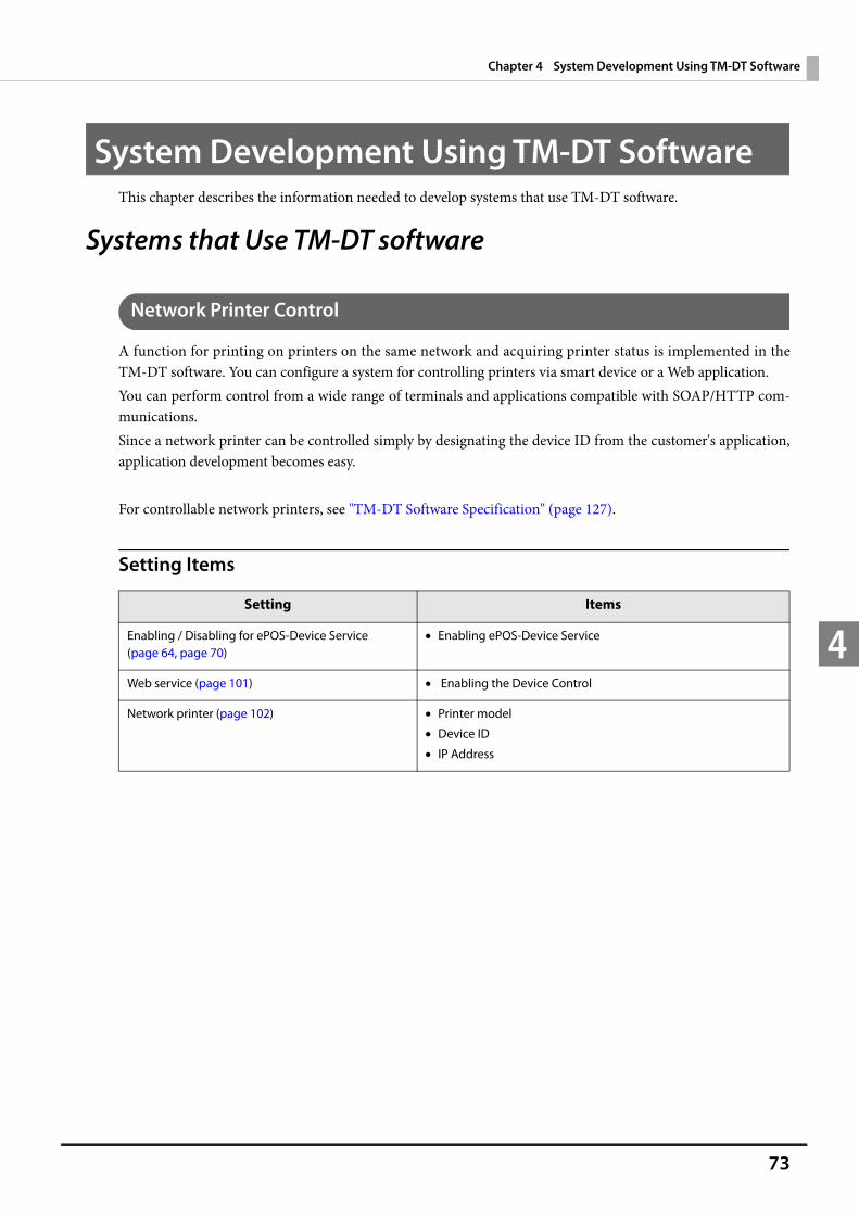
73
Chapter 4 System Development Using TM-DT Software
4
System Development Using TM-DT SoftwareThis chapter describes the information needed to develop systems that use TM-DT software.
Systems that Use TM-DT software
Network Printer Control
A function for printing on printers on the same network and acquiring printer status is implemented in the TM-DT software. You can configure a system for controlling printers via smart device or a Web application.You can perform control from a wide range of terminals and applications compatible with SOAP/HTTP com-munications.Since a network printer can be controlled simply by designating the device ID from the customer's application, application development becomes easy.
For controllable network printers, see "TM-DT Software Specification" (page 127).
Setting Items
Setting Items
Enabling / Disabling for ePOS-Device Service(page 64, page 70)
Enabling ePOS-Device Service
Web service (page 101) Enabling the Device Control
Network printer (page 102) Printer model
Device ID
IP Address

74
Chapter 4 System Development Using TM-DT Software
4
Controlling for POS Peripherals
A function for controlling POS peripherals is implemented in the TM-DT software. Communication with peripherals is controlled by device control script files based on the communication protocol with the peripher-als.You can control peripherals from socket communication compatible terminal applications. Accordingly, you can configure a system for controlling POS peripherals from smart device applications, which until now was difficult to do.
For details on controllable POS peripherals, see the ePOS-Device SDK and ePOS-Device XML user manuals.
Device control script fileThe following device control script files are registered to this product.
Device control files can be developed according to the devices that are used by the customer. For details. see the ePOS-Device SDK and ePOS-Device XML User's Manuals.
Setting Items
Device Device type
Keyboard Key input device
Barcode scanner
Serial communication device Serial communication device
Setting Items
Enabling / Disabling ePOS-Device Service (page 64, page 70)
Enabling ePOS-Device Service
Web service (page 101) Enabling the Device Control
Customer display (page 103) Use / Do not use
Key input device (page 104) Device ID
Select the device control script
Serial communication device (page 105) Device ID
Select the device control script
Communication settings
Other device (page 106) Device ID
Select the device control script
Device control script (page 106) Registering the device control script

75
Chapter 4 System Development Using TM-DT Software
4
Spooler and Forward Printing
SpoolerA spooler for saving print data and conducting background printing is implemented in the TM-DT software. Even in systems where multiple print jobs are concentrated, an application system can be configured where response is not impeded.This can be used in TM-DT software Ver.3.0 or later.General printing applications finish transactions upon confirming the printing. Due to such waiting, response times deteriorate in systems where multiple print jobs are concentrated. The spooler application stores print data and immediately returns the printing results to the application. This allows the application to proceed to the next operation without waiting for the current printing job to be completed.
Processing Flow using the Spooler Function
< Device C>
< Device B>
< Device A>
Print data
<Spooler>
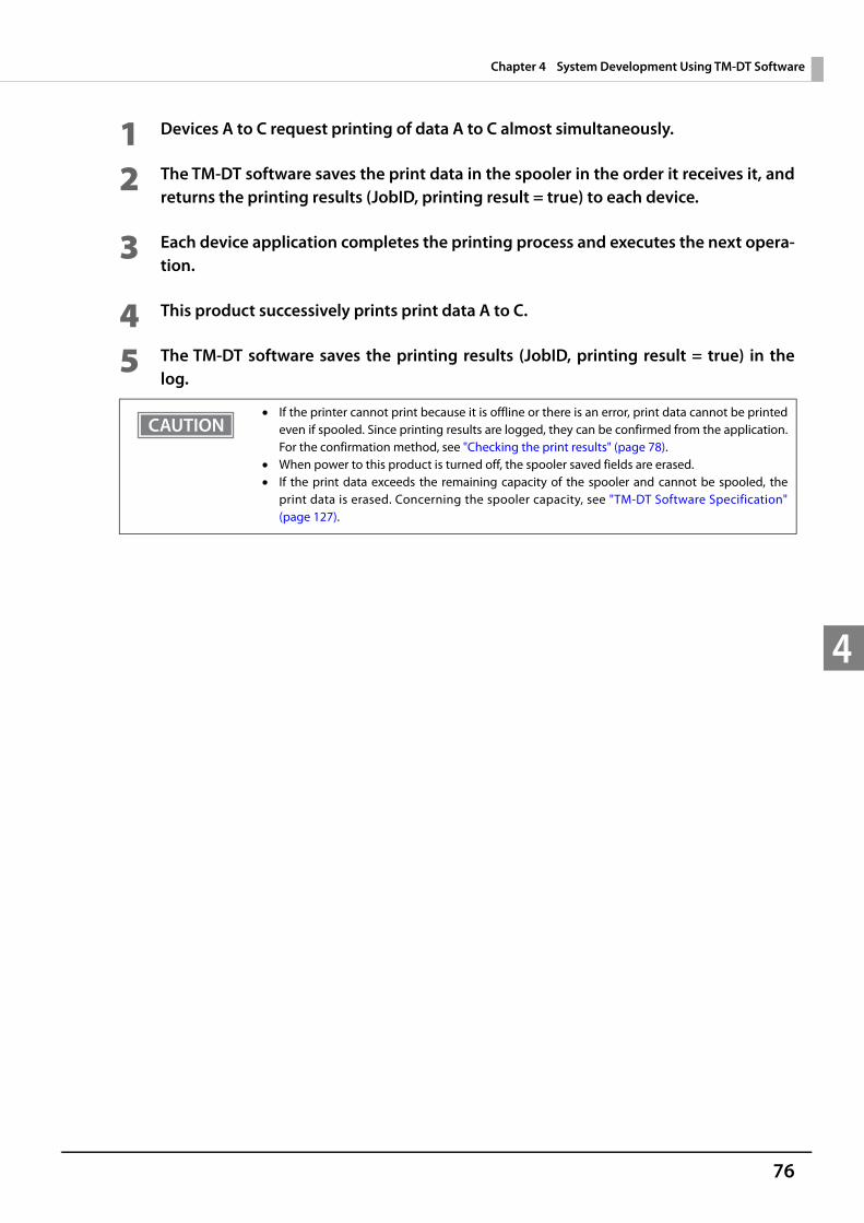
76
Chapter 4 System Development Using TM-DT Software
4
1 Devices A to C request printing of data A to C almost simultaneously.
2 The TM-DT software saves the print data in the spooler in the order it receives it, and returns the printing results (JobID, printing result = true) to each device.
3 Each device application completes the printing process and executes the next opera-tion.
4 This product successively prints print data A to C.
5 The TM-DT software saves the printing results (JobID, printing result = true) in the log.
If the printer cannot print because it is offline or there is an error, print data cannot be printed even if spooled. Since printing results are logged, they can be confirmed from the application. For the confirmation method, see "Checking the print results" (page 78).
When power to this product is turned off, the spooler saved fields are erased. If the print data exceeds the remaining capacity of the spooler and cannot be spooled, the
print data is erased. Concerning the spooler capacity, see "TM-DT Software Specification" (page 127).
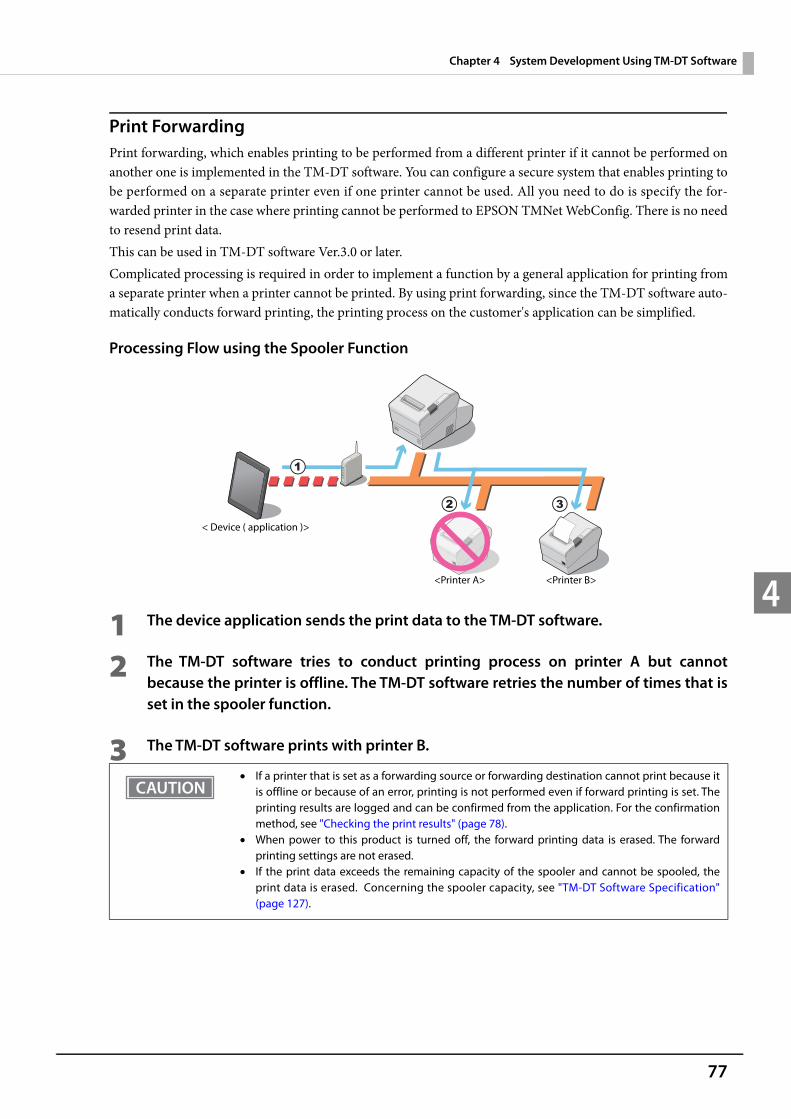
77
Chapter 4 System Development Using TM-DT Software
4
Print ForwardingPrint forwarding, which enables printing to be performed from a different printer if it cannot be performed on another one is implemented in the TM-DT software. You can configure a secure system that enables printing to be performed on a separate printer even if one printer cannot be used. All you need to do is specify the for-warded printer in the case where printing cannot be performed to EPSON TMNet WebConfig. There is no need to resend print data.This can be used in TM-DT software Ver.3.0 or later.Complicated processing is required in order to implement a function by a general application for printing from a separate printer when a printer cannot be printed. By using print forwarding, since the TM-DT software auto-matically conducts forward printing, the printing process on the customer's application can be simplified.
Processing Flow using the Spooler Function
1 The device application sends the print data to the TM-DT software.
2 The TM-DT software tries to conduct printing process on printer A but cannot because the printer is offline. The TM-DT software retries the number of times that is set in the spooler function.
3 The TM-DT software prints with printer B.
If a printer that is set as a forwarding source or forwarding destination cannot print because it is offline or because of an error, printing is not performed even if forward printing is set. The printing results are logged and can be confirmed from the application. For the confirmation method, see "Checking the print results" (page 78).
When power to this product is turned off, the forward printing data is erased. The forward printing settings are not erased.
If the print data exceeds the remaining capacity of the spooler and cannot be spooled, the print data is erased. Concerning the spooler capacity, see "TM-DT Software Specification" (page 127).
<Printer A> <Printer B>
< Device ( application )>

78
Chapter 4 System Development Using TM-DT Software
4
Checking the print results
When the spooler is disabledAfter printing, the job ID and print results are returned to the application. Also, when printing cannot be per-formed, the job ID, print results, and error code are returned.
When the spooler is enabled When print data cannot be spooled:
[JobID, Print result = false, Error code = EX_SPOOLER (spooler stopped)] is returned to the application. When print data can be spooled:
After spooling the print data, [JobID, Print result = true] is returned to the application. Printing is not per-formed at this point. Make an inquiry from the application to this product to confirm if printing was per-formed.
Checking the print results from the applicationIf inquired of print result from the application, the product returns the following information. Printing succeeded: [JobID, Print results = true] Printing succeeded: [JobID, Print result = false, Error code = Printer status] Printing or print forwarding: [JobID, Print result = false, Error code = Printing]
Setting ItemsSpooler and forward printing are configured on the same page.
When this product is turned off, data in the spooler and the log storage area is cleared. For detail, see "TM-DT Software Specification" (page 127).
When printing cannot be performed with this products spooler or print forwarding, the print data is cleared. If printing has not been completed when checking in the application, we rec-ommend reprinting.
Setting Items
Enabling / Disabling ePOS-Device Service (page 64, page 70)
Enabling ePOS-Device Service
Web service (page 101) Enabling spooler
Print forwarding (page 107) Retry count
Forwarding message
Print forwarding route
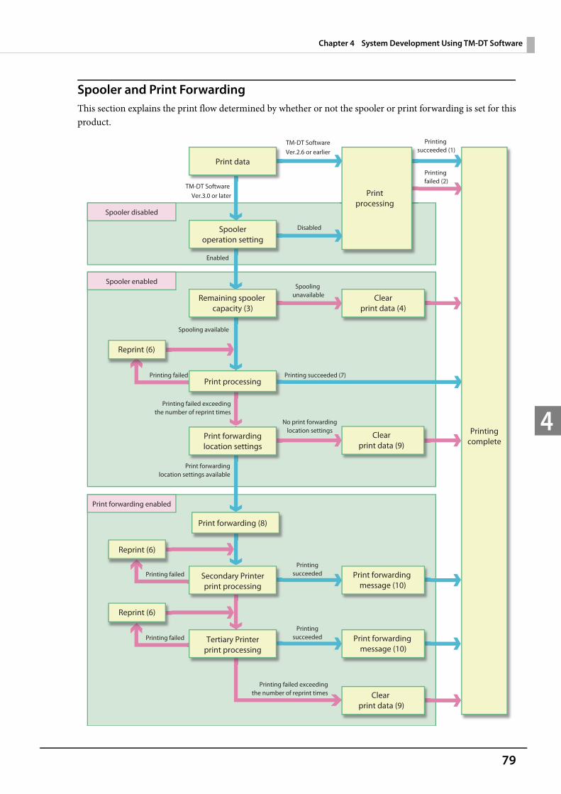
79
Chapter 4 System Development Using TM-DT Software
4
Spooler and Print ForwardingThis section explains the print flow determined by whether or not the spooler or print forwarding is set for this product.
Print data
Spooleroperation setting
Print processing
Secondary Printerprint processing
Spooler disabled
Spooler enabled
Print forwarding enabled
Printprocessing
Printingcomplete
TM-DT SoftwareVer.2.6 or earlier
Disabled
Spooling unavailable
Enabled
Print forwardinglocation settings available
Printing failed
Printing failed exceedingthe number of reprint times
Printing failed exceedingthe number of reprint times
TM-DT Software Ver.3.0 or later
Printing succeeded (1)
Printingsucceeded
Tertiary Printerprint processing
No print forwardinglocation settings
Remaining spooler capacity (3)
Printing failed (2)
Clearprint data (4)
Reprint (6)
Printing failed
Reprint (6)
Spooling available
Printing succeeded (7)
Clear print data (9)
Print forwarding message (10)
Clearprint data (9)
PrintingsucceededPrinting failed
Reprint (6)
Print forwarding (8)
Print forwardinglocation settings
Print forwarding message (10)
80
Chapter 4 System Development Using TM-DT Software
4
When spooler is disabled or TM-DT Software Ver.2.6 or earlier1: Printing success
TM-DT Software Ver.2.6 or earlier: [Print result = true] is returned to the application.TM-DT Software Ver.3.0 or later: [JobID, Print result = true] is returned to the application.
2: Printing failedTM-DT Software Ver.2.6 or earlier: Settings[Print result = false, Error code = Printer status]
is returned to the application.TM-DT Software Ver.3.0 or later: [JobID, Print result = false, Error code = Printer status]
is returned to the application.
When spooler is enabled3: The remaining free space in the spooler and the size of the print data is checked, and the product determines
whether or not the print data can be spooled.4: If the print data cannot be spooled, the print data is cleared. [JobID, Print result = false, Error code =
EX_SPOOLER (spooler stopped)] is returned to the application. This data is not stored in the product's spooler or the log storage area.
5: When print data can be spooled, [JobID, Print result = true] is stored in the spooler. [JobID, Print result = true] is also returned to the application.
6: Make the reprint settings (number of times and interval) in EPSON TMNet WebConfig. For detail, see "Set-tings - Web service settings - Print Settings - Spooler" (page 107).
7: When printing is successful, the spooler's print data and [JobID, Print result = true] are deleted. [JobID, Print result = true] are stored in the log storage area of this product.
When Print forwarding is enabled8: Send print data to Secondary printer.9: When printing fails, the spooler's print data and [JobID, Print result = true] are deleted. [JobID, Print result =
false, Error code = Printer status] are stored in the log storage area of this product.10:Print with secondary (tertiary) printer. For about settings for forwarding message, see "Settings - Web service
settings - Print Settings - Spooler" (page 107).
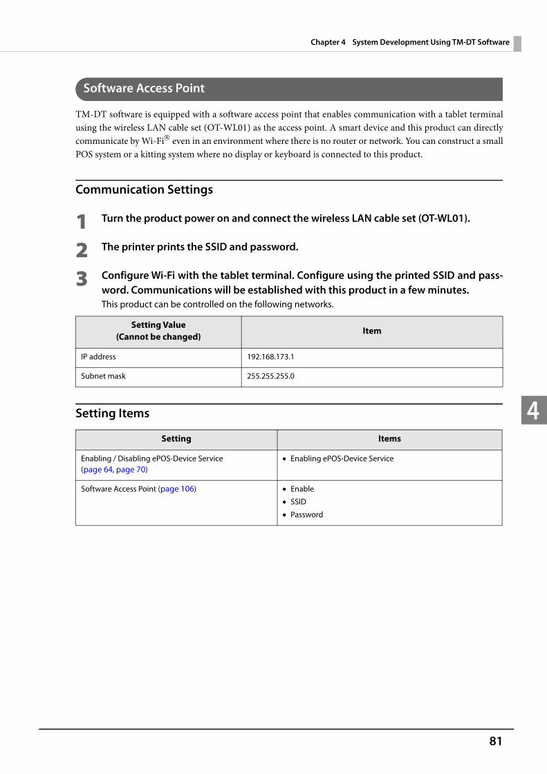
81
Chapter 4 System Development Using TM-DT Software
4
Software Access Point
TM-DT software is equipped with a software access point that enables communication with a tablet terminal using the wireless LAN cable set (OT-WL01) as the access point. A smart device and this product can directly communicate by Wi-Fi even in an environment where there is no router or network. You can construct a small POS system or a kitting system where no display or keyboard is connected to this product.
Communication Settings
1 Turn the product power on and connect the wireless LAN cable set (OT-WL01).
2 The printer prints the SSID and password.
3 Configure Wi-Fi with the tablet terminal. Configure using the printed SSID and pass-word. Communications will be established with this product in a few minutes. This product can be controlled on the following networks.
Setting Items
Setting Value(Cannot be changed)
Item
IP address 192.168.173.1
Subnet mask 255.255.255.0
Setting Items
Enabling / Disabling ePOS-Device Service (page 64, page 70)
Enabling ePOS-Device Service
Software Access Point (page 106) Enable
SSID
Password
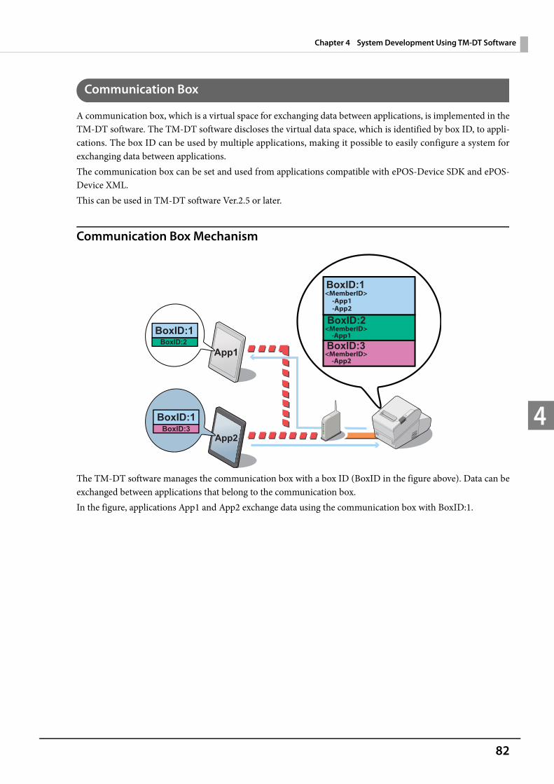
82
Chapter 4 System Development Using TM-DT Software
4
Communication Box
A communication box, which is a virtual space for exchanging data between applications, is implemented in the TM-DT software. The TM-DT software discloses the virtual data space, which is identified by box ID, to appli-cations. The box ID can be used by multiple applications, making it possible to easily configure a system for exchanging data between applications.The communication box can be set and used from applications compatible with ePOS-Device SDK and ePOS-Device XML.This can be used in TM-DT software Ver.2.5 or later.
Communication Box Mechanism
The TM-DT software manages the communication box with a box ID (BoxID in the figure above). Data can be exchanged between applications that belong to the communication box.In the figure, applications App1 and App2 exchange data using the communication box with BoxID:1.
<MemberID>
<MemberID>
<MemberID>
-App1-App2
-App1
-App2
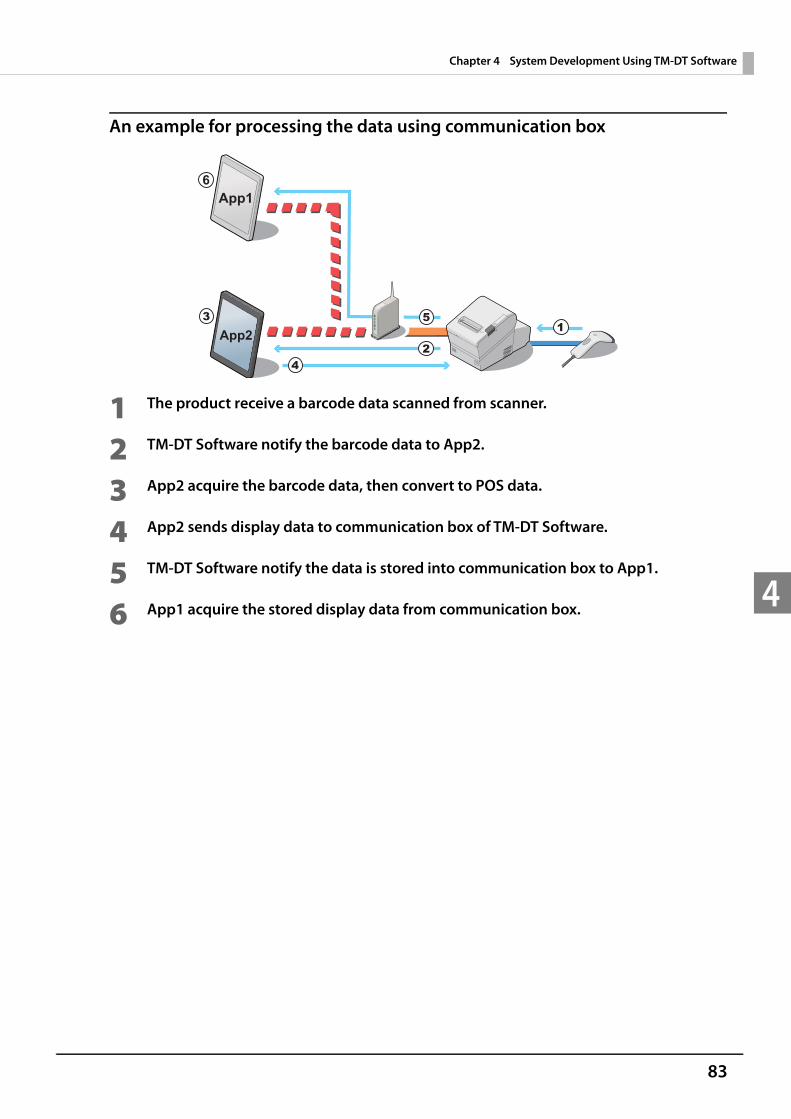
83
Chapter 4 System Development Using TM-DT Software
4
An example for processing the data using communication box
1 The product receive a barcode data scanned from scanner.
2 TM-DT Software notify the barcode data to App2.
3 App2 acquire the barcode data, then convert to POS data.
4 App2 sends display data to communication box of TM-DT Software.
5 TM-DT Software notify the data is stored into communication box to App1.
6 App1 acquire the stored display data from communication box.

84
Chapter 4 System Development Using TM-DT Software
4
Server Direct Print
Server Direct Print is implemented in the TM-DT software. The function allows the TM-DT software to issue printing requests to Web server applications, conduct printing upon directly acquiring print data from the Web server, and notify the printing results to applications.General printing system applications perform printing upon designating the printer. A function for including ePOS-Print XML print data in response to printing requests can be implemented in server direct print applica-tions. Since the printer IP address is not specified from the application, printing can be performed via the inter-net even in environments where printing is difficult because the IP address cannot be acquired on the Web server side or the device cannot be controlled via the internet due to security policy settings.Because the Web server application only includes print data in the response, printing can be performed without designating the printer.
Processing Flow Using the Server Direct Print Function
1 The TM-DT software issues a print request to the Web server application.
2 The Web server application sends a response that includes print data to the TM-DT software.
3 The TM-DT software sends print data to the printer and performs printing.
4 The software notifies the printing results to the application.
Items to be Prepared by the Customer Web server Application for including print data in the responses to requests from the TM-DT software
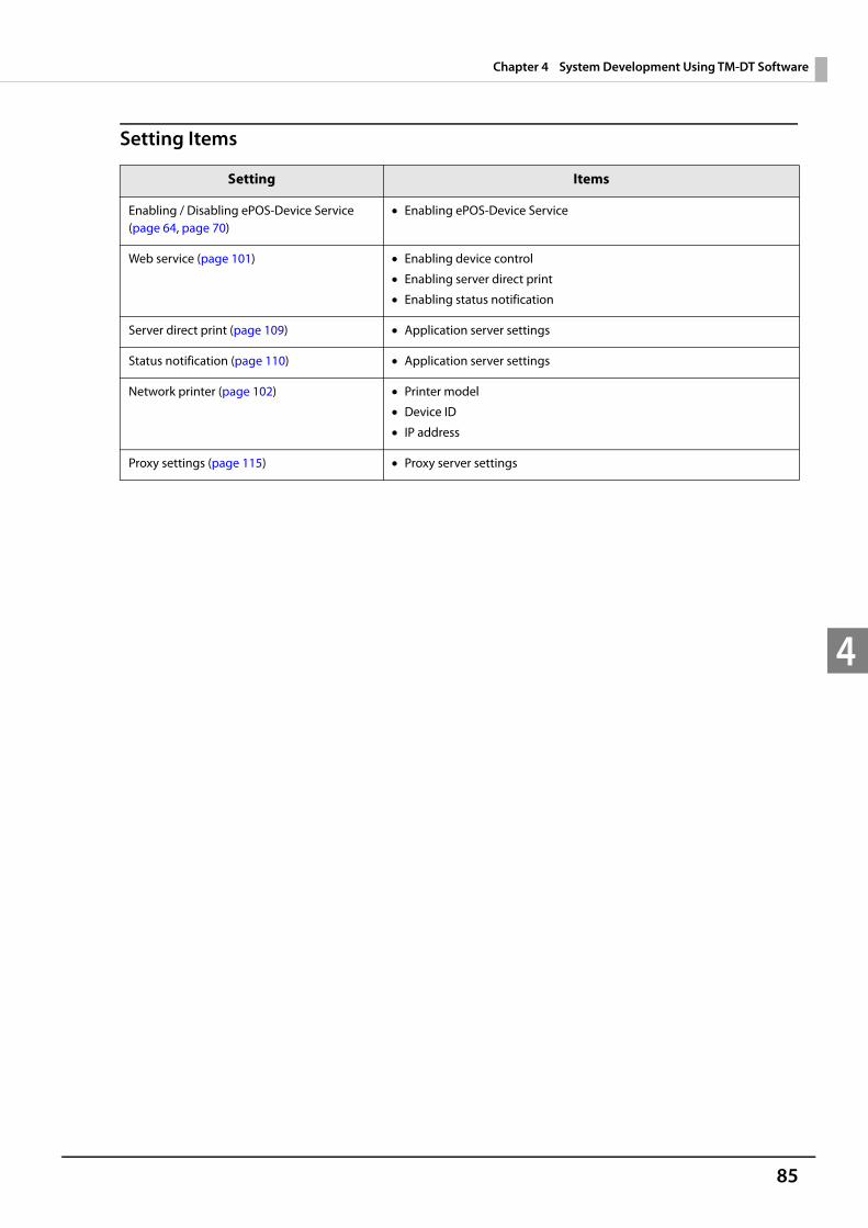
85
Chapter 4 System Development Using TM-DT Software
4
Setting Items
Setting Items
Enabling / Disabling ePOS-Device Service (page 64, page 70)
Enabling ePOS-Device Service
Web service (page 101) Enabling device control
Enabling server direct print
Enabling status notification
Server direct print (page 109) Application server settings
Status notification (page 110) Application server settings
Network printer (page 102) Printer model
Device ID
IP address
Proxy settings (page 115) Proxy server settings
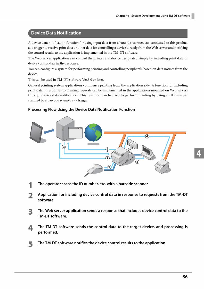
86
Chapter 4 System Development Using TM-DT Software
4
Device Data Notification
A device data notification function for using input data from a barcode scanner, etc. connected to this product as a trigger to receive print data or other data for controlling a device directly from the Web server and notifying the control results to the application is implemented in the TM-DT software.The Web server application can control the printer and device designated simply by including print data or device control data in the response. You can configure a system for performing printing and controlling peripherals based on data notices from the device. This can be used in TM-DT software Ver.3.0 or later.General printing system applications commence printing from the application side. A function for including print data in responses to printing requests cab be implemented in the applications mounted on Web servers through device data notification. This function can be used to perform printing by using an ID number scanned by a barcode scanner as a trigger.
Processing Flow Using the Device Data Notification Function
1 The operator scans the ID number, etc. with a barcode scanner.
2 Application for including device control data in response to requests from the TM-DT software
3 The Web server application sends a response that includes device control data to the TM-DT software.
4 The TM-DT software sends the control data to the target device, and processing is performed.
5 The TM-DT software notifies the device control results to the application.
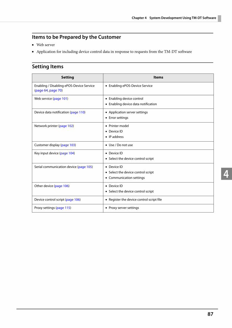
87
Chapter 4 System Development Using TM-DT Software
4
Items to be Prepared by the Customer Web server Application for including device control data in response to requests from the TM-DT software
Setting Items
Setting Items
Enabling / Disabling ePOS-Device Service (page 64, page 70)
Enabling ePOS-Device Service
Web service (page 101) Enabling device control
Enabling device data notification
Device data notification (page 110) Application server settings
Error settings
Network printer (page 102) Printer model
Device ID
IP address
Customer display (page 103) Use / Do not use
Key input device (page 104) Device ID
Select the device control script
Serial communication device (page 105) Device ID
Select the device control script
Communication settings
Other device (page 106) Device ID
Select the device control script
Device control script (page 106) Register the device control script file
Proxy settings (page 115) Proxy server settings
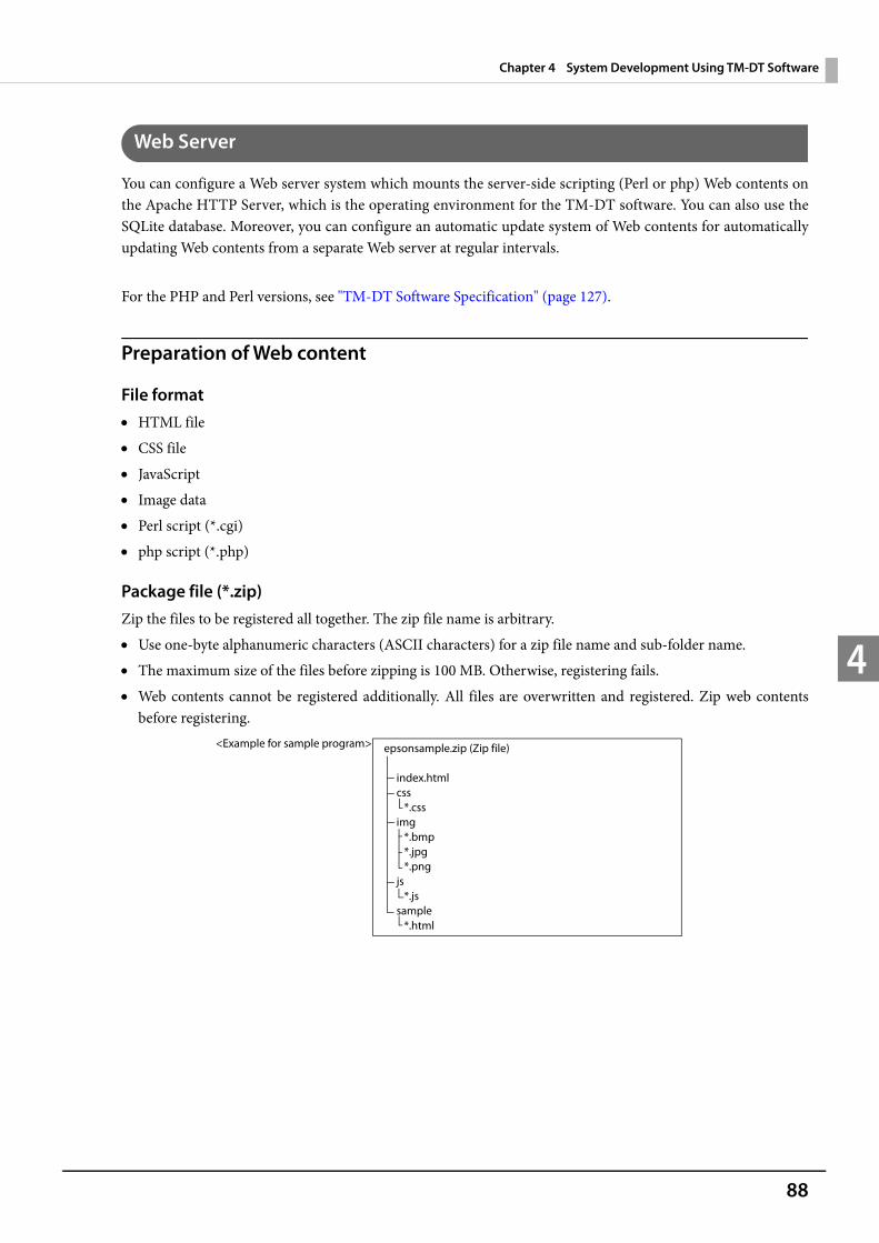
88
Chapter 4 System Development Using TM-DT Software
4
Web Server
You can configure a Web server system which mounts the server-side scripting (Perl or php) Web contents on the Apache HTTP Server, which is the operating environment for the TM-DT software. You can also use the SQLite database. Moreover, you can configure an automatic update system of Web contents for automatically updating Web contents from a separate Web server at regular intervals.
For the PHP and Perl versions, see "TM-DT Software Specification" (page 127).
Preparation of Web content
File format HTML file CSS file JavaScript Image data Perl script (*.cgi) php script (*.php)
Package file (*.zip)Zip the files to be registered all together. The zip file name is arbitrary. Use one-byte alphanumeric characters (ASCII characters) for a zip file name and sub-folder name. The maximum size of the files before zipping is 100 MB. Otherwise, registering fails. Web contents cannot be registered additionally. All files are overwritten and registered. Zip web contents
before registering.
epsonsample.zip (Zip file)
index.html css *.css img *.bmp *.jpg *.png js *.js sample *.html
<Example for sample program>
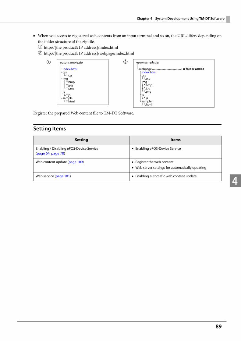
89
Chapter 4 System Development Using TM-DT Software
4
When you access to registered web contents from an input terminal and so on, the URL differs depending on the folder structure of the zip file.➀ http://[the product’s IP address]/index.html➁ http://[the product’s IP address]/webpage/index.html
Register the prepared Web content file to TM-DT Software.
Setting Items
Setting Items
Enabling / Disabling ePOS-Device Service (page 64, page 70)
Enabling ePOS-Device Service
Web content update (page 109) Register the web content
Web server settings for automatically updating
Web service (page 101) Enabling automatic web content update
epsonsample.zip
webpage .................................. : A folder added index.html css *.css img *.bmp *.jpg *.png js *.js sample *.html
epsonsample.zip
index.htmlcss
*.cssimg
*.bmp*.jpg*.png
js*.js
sample*.html
➀ ➁

90
Chapter 4 System Development Using TM-DT Software
4
Method Used to Set multiple TM-DT devices
To install and operate multiple this products you will need to set IP addresses for each device and configure var-ious printing control settings.The following method is available in order to configure settings efficiently. Configure settings for each device separately using EPSON TMNet WebConfig
Basic setup procedure. Connect a keyboard and a display to the TM-DT devices and have a worker setup each device individually. Save and register web content and certificate files to a USB memory stick or similar storage device.See "TM-DT Software Settings" on page 97 for more information on this method.
Configure settings using a TM-DT software settings file saved to a USB memory stickThis method is used to have the product automatically configure settings from the settings file on the USB memory stick. When doing so a user does not need to connect a keyboard and display to perform operations. This is the conventional Easy Setup method.Prepare a settings file (setting.ini) with TM-DT settings on a Windows computer. Then, put this settings file along with web content and the certificate file onto a USB memory stick. A separate USB memory stick for each TM-DT will need to be prepared when setting IP addresses for multi-ple TM-DT devices individually.See "Deployment Guide" for more information on this method.
Configure settings by building a configuration server systemThis method automatically applies settings using the settings file downloaded by the TM-DT based on a request sent to the configuration server.This allows for a more efficient configuration system through the setting of functions used to configure indi-vidual settings, such as different IP addresses for each TM-DT, on the configuration server.First, build a configuration server system and prepare TM-DT settings data to include TM-DT settings, web content and the certificate file. You will need to configure settings for the TM-DT so that it sends the request to the configuration server.See "Deployment Guide" for more information on this method.
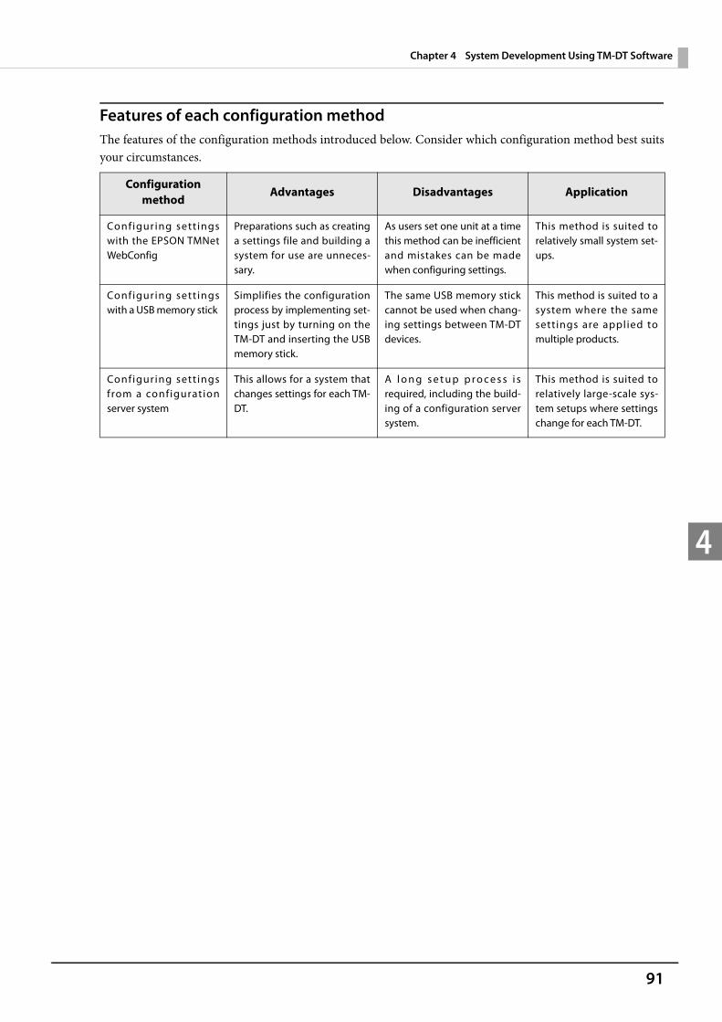
91
Chapter 4 System Development Using TM-DT Software
4
Features of each configuration methodThe features of the configuration methods introduced below. Consider which configuration method best suits your circumstances.
Configuration method
Advantages Disadvantages Application
Configur ing sett ings with the EPSON TMNet WebConfig
Preparations such as creating a settings file and building a system for use are unneces-sary.
As users set one unit at a time this method can be inefficient and mistakes can be made when configuring settings.
This method is suited to relatively small system set-ups.
Configur ing sett ings with a USB memory stick
Simplifies the configuration process by implementing set-tings just by turning on the TM-DT and inserting the USB memory stick.
The same USB memory stick cannot be used when chang-ing settings between TM-DT devices.
This method is suited to a system where the same settings are applied to multiple products.
Configur ing sett ings from a configuration server system
This allows for a system that changes settings for each TM-DT.
A l o n g s e t u p p r o c e s s i s required, including the build-ing of a configuration server system.
This method is suited to relatively large-scale sys-tem setups where settings change for each TM-DT.
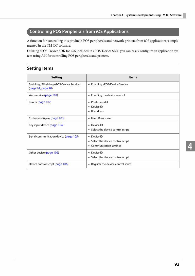
92
Chapter 4 System Development Using TM-DT Software
4
Controlling POS Peripherals from iOS Applications
A function for controlling this product's POS peripherals and network printers from iOS applications is imple-mented in the TM-DT software.Utilizing ePOS-Device SDK for iOS included in ePOS-Device SDK, you can easily configure an application sys-tem using API for controlling POS peripherals and printers.
Setting Items
Setting Items
Enabling / Disabling ePOS-Device Service (page 64, page 70)
Enabling ePOS-Device Service
Web service (page 101) Enabling the device control
Printer (page 102) Printer model
Device ID
IP address
Customer display (page 103) Use / Do not use
Key input device (page 104) Device ID
Select the device control script
Serial communication device (page 105) Device ID
Select the device control script
Communication settings
Other device (page 106) Device ID
Select the device control script
Device control script (page 106) Register the device control script
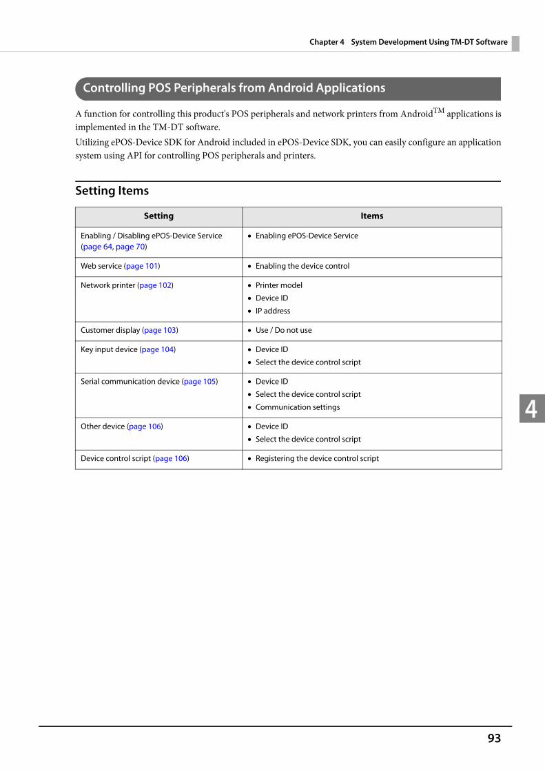
93
Chapter 4 System Development Using TM-DT Software
4
Controlling POS Peripherals from Android Applications
A function for controlling this product's POS peripherals and network printers from AndroidTM applications is implemented in the TM-DT software.Utilizing ePOS-Device SDK for Android included in ePOS-Device SDK, you can easily configure an application system using API for controlling POS peripherals and printers.
Setting Items
Setting Items
Enabling / Disabling ePOS-Device Service (page 64, page 70)
Enabling ePOS-Device Service
Web service (page 101) Enabling the device control
Network printer (page 102) Printer model
Device ID
IP address
Customer display (page 103) Use / Do not use
Key input device (page 104) Device ID
Select the device control script
Serial communication device (page 105) Device ID
Select the device control script
Communication settings
Other device (page 106) Device ID
Select the device control script
Device control script (page 106) Registering the device control script
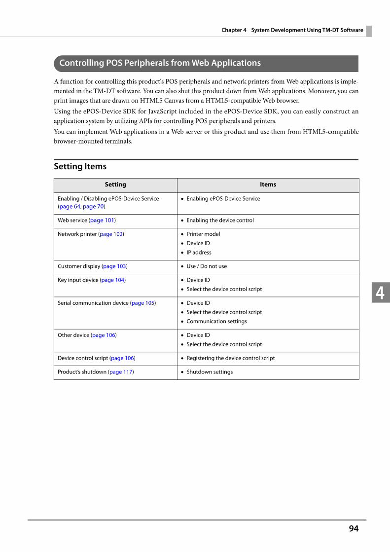
94
Chapter 4 System Development Using TM-DT Software
4
Controlling POS Peripherals from Web Applications
A function for controlling this product's POS peripherals and network printers from Web applications is imple-mented in the TM-DT software. You can also shut this product down from Web applications. Moreover, you can print images that are drawn on HTML5 Canvas from a HTML5-compatible Web browser.Using the ePOS-Device SDK for JavaScript included in the ePOS-Device SDK, you can easily construct an application system by utilizing APIs for controlling POS peripherals and printers.You can implement Web applications in a Web server or this product and use them from HTML5-compatible browser-mounted terminals.
Setting Items
Setting Items
Enabling / Disabling ePOS-Device Service (page 64, page 70)
Enabling ePOS-Device Service
Web service (page 101) Enabling the device control
Network printer (page 102) Printer model
Device ID
IP address
Customer display (page 103) Use / Do not use
Key input device (page 104) Device ID
Select the device control script
Serial communication device (page 105) Device ID
Select the device control script
Communication settings
Other device (page 106) Device ID
Select the device control script
Device control script (page 106) Registering the device control script
Product’s shutdown (page 117) Shutdown settings
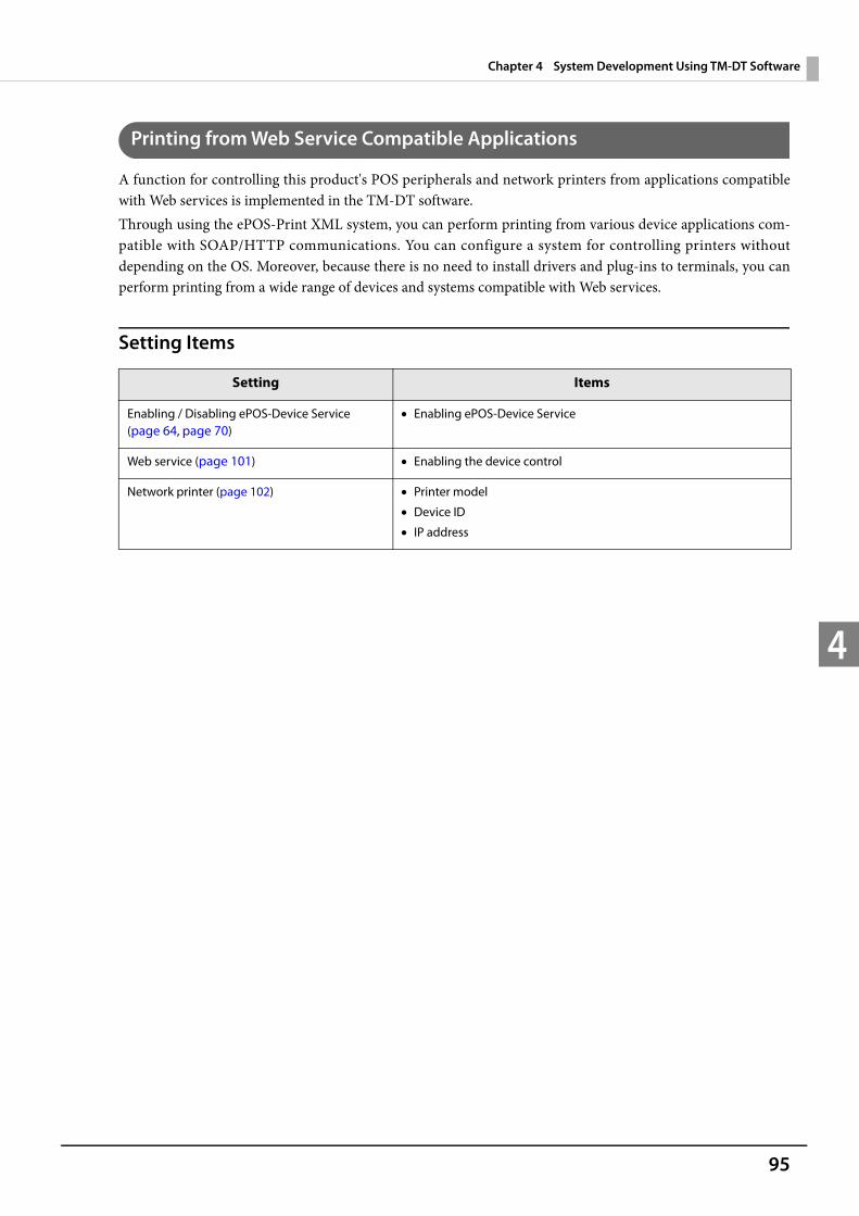
95
Chapter 4 System Development Using TM-DT Software
4
Printing from Web Service Compatible Applications
A function for controlling this product's POS peripherals and network printers from applications compatible with Web services is implemented in the TM-DT software.Through using the ePOS-Print XML system, you can perform printing from various device applications com-patible with SOAP/HTTP communications. You can configure a system for controlling printers without depending on the OS. Moreover, because there is no need to install drivers and plug-ins to terminals, you can perform printing from a wide range of devices and systems compatible with Web services.
Setting Items
Setting Items
Enabling / Disabling ePOS-Device Service (page 64, page 70)
Enabling ePOS-Device Service
Web service (page 101) Enabling the device control
Network printer (page 102) Printer model
Device ID
IP address
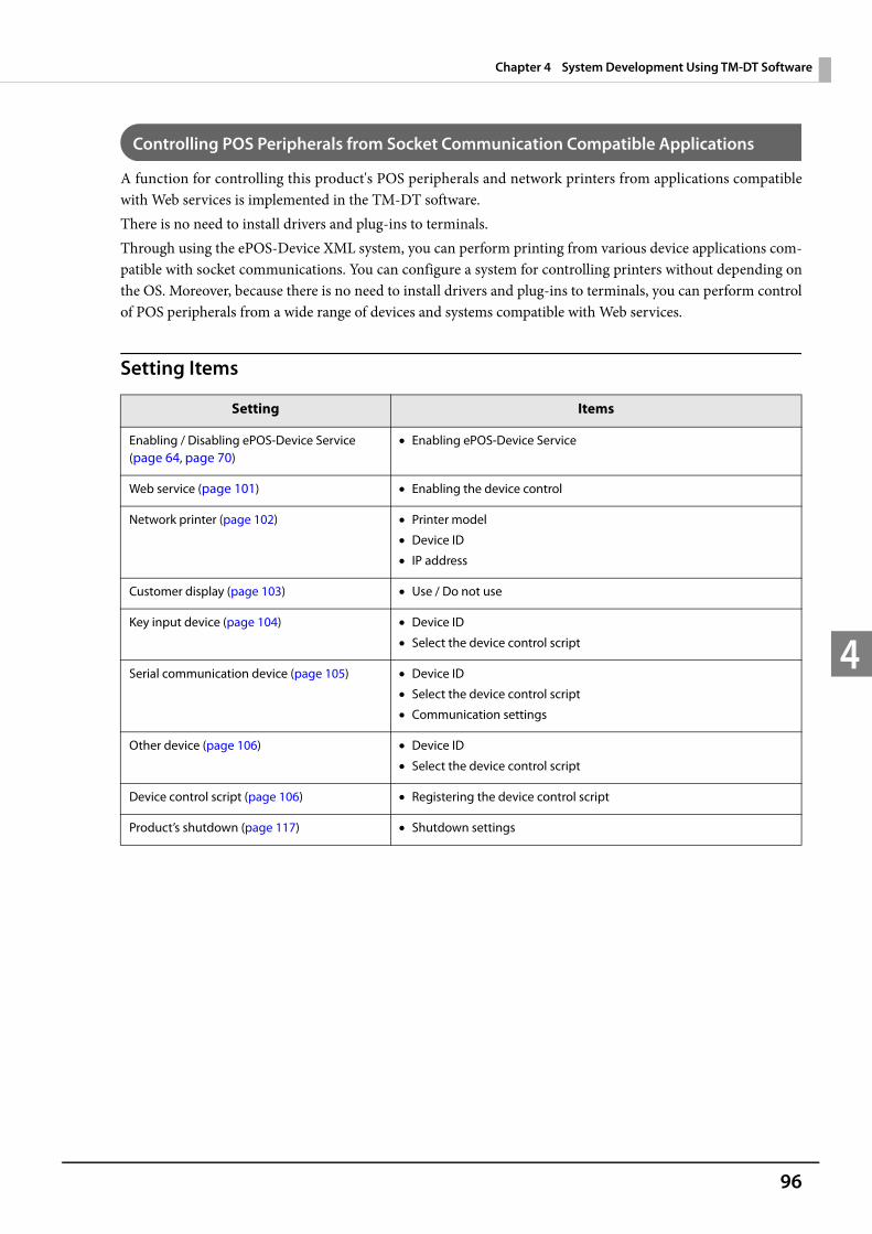
96
Chapter 4 System Development Using TM-DT Software
4
Controlling POS Peripherals from Socket Communication Compatible Applications
A function for controlling this product's POS peripherals and network printers from applications compatible with Web services is implemented in the TM-DT software.There is no need to install drivers and plug-ins to terminals. Through using the ePOS-Device XML system, you can perform printing from various device applications com-patible with socket communications. You can configure a system for controlling printers without depending on the OS. Moreover, because there is no need to install drivers and plug-ins to terminals, you can perform control of POS peripherals from a wide range of devices and systems compatible with Web services.
Setting Items
Setting Items
Enabling / Disabling ePOS-Device Service (page 64, page 70)
Enabling ePOS-Device Service
Web service (page 101) Enabling the device control
Network printer (page 102) Printer model
Device ID
IP address
Customer display (page 103) Use / Do not use
Key input device (page 104) Device ID
Select the device control script
Serial communication device (page 105) Device ID
Select the device control script
Communication settings
Other device (page 106) Device ID
Select the device control script
Device control script (page 106) Registering the device control script
Product’s shutdown (page 117) Shutdown settings
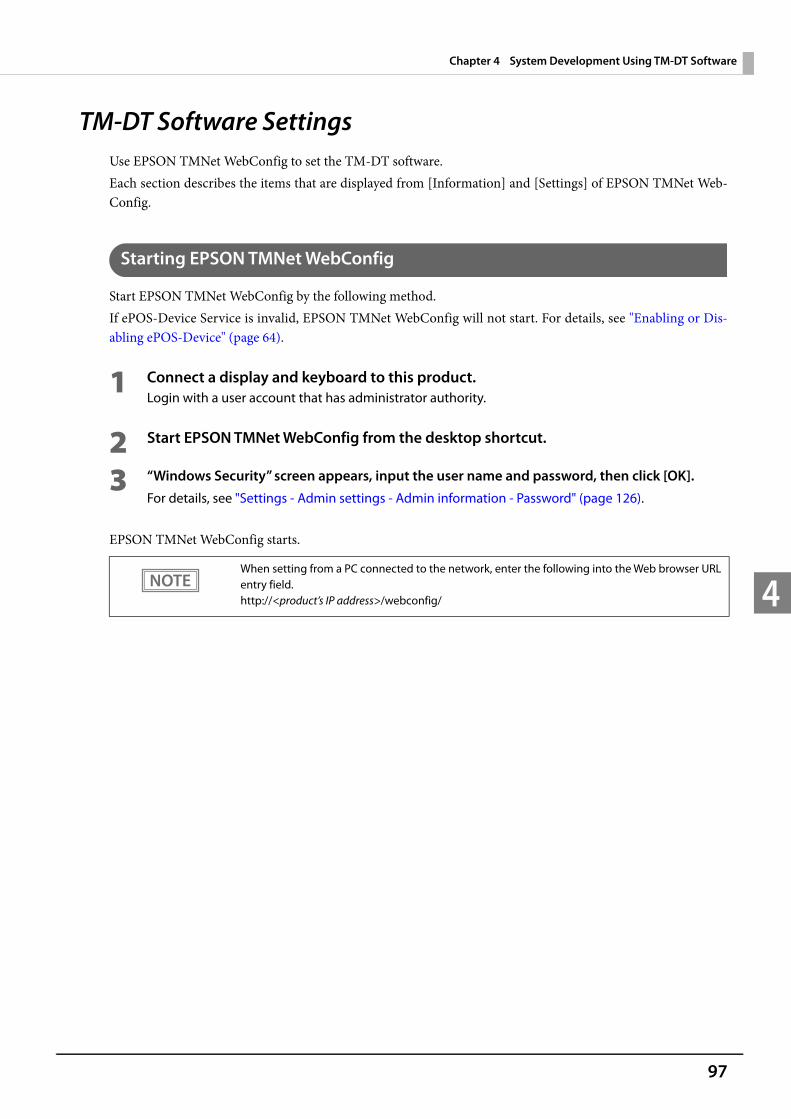
97
Chapter 4 System Development Using TM-DT Software
4
TM-DT Software Settings Use EPSON TMNet WebConfig to set the TM-DT software.Each section describes the items that are displayed from [Information] and [Settings] of EPSON TMNet Web-Config.
Starting EPSON TMNet WebConfig
Start EPSON TMNet WebConfig by the following method.If ePOS-Device Service is invalid, EPSON TMNet WebConfig will not start. For details, see "Enabling or Dis-abling ePOS-Device" (page 64).
1 Connect a display and keyboard to this product.Login with a user account that has administrator authority.
2 Start EPSON TMNet WebConfig from the desktop shortcut.
3 “Windows Security” screen appears, input the user name and password, then click [OK].For details, see "Settings - Admin settings - Admin information - Password" (page 126).
EPSON TMNet WebConfig starts.
When setting from a PC connected to the network, enter the following into the Web browser URL entry field.http://<product’s IP address>/webconfig/
98
Chapter 4 System Development Using TM-DT Software
4
Help Screen Display
Click [Help] to display the help screen for EPSON TMNet WebConfig.
Version Screen Display
Click [About] to display the version screen for EPSON TMNet WebConfig.
Updating TM-DT Software
When you update the TM-DT software, you can use its new functions. Download the following file from Epson's Web site to update. File name: ePOS-Device System Update Package
For details on how to update, see the Readme file inside the ePOS-Device update package.
You cannot downgrade the TM-DT software.

99
Chapter 4 System Development Using TM-DT Software
4
Information - Current status
You can check the basic settings for this product.
This is displayed with TM-DT software Ver.3.0 or later.
Item Description
Admin infor-mation
Administrator name Displays the administrator name for this product.
Installation location Displays the installation location for this product.
We b s e r v i c e function
Web service function Displays whether the Web service function is enabled or not.
Status of Web content update
Automatic update for Web con-tent
Displays the schedule for automatic updates for Web content.
Date and time of Web content installed
Displays the date and time that the Web contents were installed.
Date and time of last automatic update
Displays the date and time of the last automatic update performed.
Result of automatic update Displays the result of the automatic update.
Server direct print
Server 1
Server 2 *
Server 3 *
Run state Displays the run state of the server direct print.
ID Displays the web server ID acquiring print data of the server direct print.
Interval (sec.) Displays the interval for acquiring print data.
Date and time last run
Displays the date and time last run of the server direct print.
F i n a l r u n results
Displays the final run results of the server direct print.
Status notifica-tion
Run state Status notifi-cation
Displays the run state of the status notification.
ID Displays the web server ID sending status notification.
Interval (sec.) Displays the interval for sending status notification.
Date and time last run
Displays the date and time last run of the status notification.
F i n a l r u n results
Displays the final run results of the status notification.
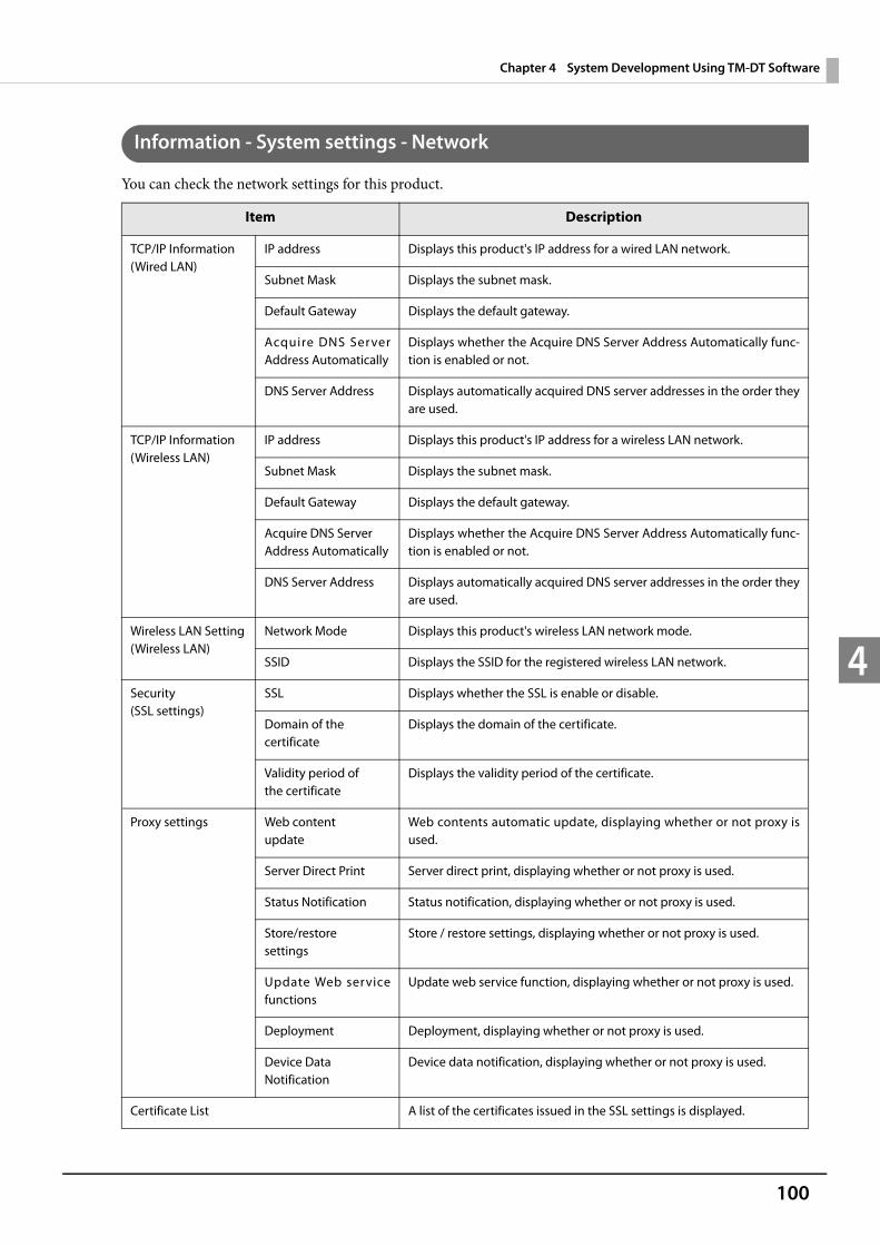
100
Chapter 4 System Development Using TM-DT Software
4
Information - System settings - Network
You can check the network settings for this product.
Item Description
TCP/IP Information(Wired LAN)
IP address Displays this product's IP address for a wired LAN network.
Subnet Mask Displays the subnet mask.
Default Gateway Displays the default gateway.
Acquire DNS Server Address Automatically
Displays whether the Acquire DNS Server Address Automatically func-tion is enabled or not.
DNS Server Address Displays automatically acquired DNS server addresses in the order they are used.
TCP/IP Information(Wireless LAN)
IP address Displays this product's IP address for a wireless LAN network.
Subnet Mask Displays the subnet mask.
Default Gateway Displays the default gateway.
Acquire DNS Server Address Automatically
Displays whether the Acquire DNS Server Address Automatically func-tion is enabled or not.
DNS Server Address Displays automatically acquired DNS server addresses in the order they are used.
Wireless LAN Setting(Wireless LAN)
Network Mode Displays this product's wireless LAN network mode.
SSID Displays the SSID for the registered wireless LAN network.
Security(SSL settings)
SSL Displays whether the SSL is enable or disable.
Domain of the certificate
Displays the domain of the certificate.
Validity period of the certificate
Displays the validity period of the certificate.
Proxy settings Web content update
Web contents automatic update, displaying whether or not proxy is used.
Server Direct Print Server direct print, displaying whether or not proxy is used.
Status Notification Status notification, displaying whether or not proxy is used.
Store/restore settings
Store / restore settings, displaying whether or not proxy is used.
Update Web service functions
Update web service function, displaying whether or not proxy is used.
Deployment Deployment, displaying whether or not proxy is used.
Device Data Notification
Device data notification, displaying whether or not proxy is used.
Certificate List A list of the certificates issued in the SSL settings is displayed.

101
Chapter 4 System Development Using TM-DT Software
4
Information - System settings - Date and Time
You can check this product's time settings.
Settings - Web service settings - Startup settings
Enables or disables the Web services that are provided with the TM-DT software.
This can be used in TM-DT software Ver.3.0 or later.
Item Description
Date and Time Displays the time and the time zone set for this product.
Automatically adjust clock for Daylight Saving Time
Displays whether the automatic daylight saving time adjustment function is enabled or not.
Use Time Server Displays whether the function to use a time server is enabled or not.
Time Server Displays the address set as a time server.
Item Description
Web service function
Device control Enables or disables device control functions that use Web service. Used for ePOS-Device.
Automatic update of Web content
Enables or disables the automatic update function for Web content.
Server direct print Enables or disables the server direct print function.
Status notification Enables or disables the status notification function.
Device data notification Enables or disables the device data notification function.
The automatic registra-tion and deletion of the key input device
Enables or disables the automatic registration / deletion function of the key input device.
Apply Registers the settings to this product.
Print function Spooler * Enables or disables the spooler function.
Apply Registers the settings to this product.
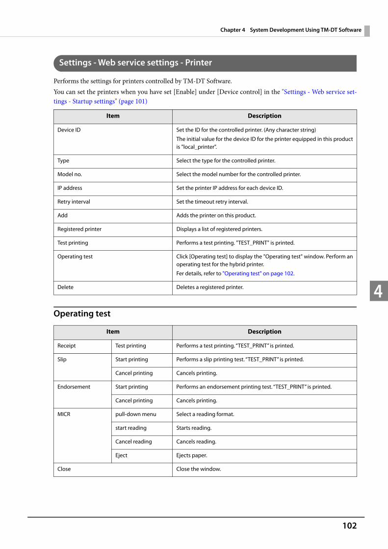
102
Chapter 4 System Development Using TM-DT Software
4
Settings - Web service settings - Printer
Performs the settings for printers controlled by TM-DT Software.You can set the printers when you have set [Enable] under [Device control] in the "Settings - Web service set-tings - Startup settings" (page 101)
Operating test
Item Description
Device ID Set the ID for the controlled printer. (Any character string)
The initial value for the device ID for the printer equipped in this product is "local_printer".
Type Select the type for the controlled printer.
Model no. Select the model number for the controlled printer.
IP address Set the printer IP address for each device ID.
Retry interval Set the timeout retry interval.
Add Adds the printer on this product.
Registered printer Displays a list of registered printers.
Test printing Performs a test printing. "TEST_PRINT" is printed.
Operating test Click [Operating test] to display the "Operating test" window. Perform an operating test for the hybrid printer.
Fer details, refer to "Operating test" on page 102.
Delete Deletes a registered printer.
Item Description
Receipt Test printing Performs a test printing. “TEST_PRINT” is printed.
Slip Start printing Performs a slip printing test. “TEST_PRINT” is printed.
Cancel printing Cancels printing.
Endorsement Start printing Performs an endorsement printing test. “TEST_PRINT” is printed.
Cancel printing Cancels printing.
MICR pull-down menu Select a reading format.
start reading Starts reading.
Cancel reading Cancels reading.
Eject Ejects paper.
Close Close the window.

103
Chapter 4 System Development Using TM-DT Software
4
Settings - Web service settings - Customer Display
Performs the settings for the customer display controlled by TM-DT Software.You can set the customer display when you have set [Enable] under [Device control] in the "Settings - Web ser-vice settings - Startup settings" (page 101)
Item Description
Do not use Do not use a customer display.
Use Use a customer display.
Communication settings
Communication speed (bps)
Set the communication speed.
Data bit Set the data bit.
Parity Set the parity.
Brightness setting Set the brightness of the customer display in percentages.
You can set 20%, 40%, 60%, or 100%. The maximum brightness is 100%.
Display test Check if the customer display operates properly.
When [Display test] is clicked, characters appear on the customer display.
Apply Registers the settings to this product.
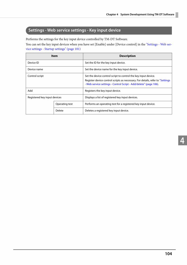
104
Chapter 4 System Development Using TM-DT Software
4
Settings - Web service settings - Key input device
Performs the settings for the key input device controlled by TM-DT Software.You can set the key input devices when you have set [Enable] under [Device control] in the "Settings - Web ser-vice settings - Startup settings" (page 101)
Item Description
Device ID Set the ID for the key input device.
Device name Set the device name for the key input device.
Control script Set the device control script to control the key input device.
Register device control scripts as necessary. For details, refer to "Settings - Web service settings - Control Script - Add/delete" (page 106).
Add Registers the key input device.
Registered key input devices Displays a list of registered key input devices.
Operating test Performs an operating test for a registered key input device.
Delete Deletes a registered key input device.

105
Chapter 4 System Development Using TM-DT Software
4
Settings - Web Service settings - Serial communication Device
Performs the settings for serial communication devices controlled by TM-DT Software.You can set the serial communication devices when you have set [Enable] under [Device control] in the "Set-tings - Web service settings - Startup settings" (page 101)
Item Description
Device ID Set the device ID.
D e v i c e name
Model selection Select the device model name.
Port selection Select the device port.
Physical serial port
Serial port on the rear of this product.
USB port 1 ~ 6 USB ports on the rear of this product.
If connecting a serial device using the COM-USB cable, select the appro-priate USB port.
The USB port numbers can be confirmed on [Display port location].
Display port location Displays the window that shows this product's port positions.
Control script Select the device control script for controlling the serial communication device.
Register device control scripts as necessary. For details, refer to "Settings - Web service settings - Control Script - Add/delete" (page 106).
Communication speed (bps) Set the device communication speed.
Data bit Set the data bit.
Parity Set the parity.
Stop bit Set the stop bit.
Flow control Set the flow control.
Add Registers the serial communication device on this product.
Registered serial communication device
Displays a list of registered serial communication devices.
Detailed display Displays the device settings confirmation window.
Operating test Performs an operating test for a registered serial communication device.
1. Click to display the "Operating Test" window.
2. Enter a value and click [Send].
3. Confirm that correct operation is performed.
Delete Deletes a registered serial communication device.

106
Chapter 4 System Development Using TM-DT Software
4
Settings - Web Service settings - Other Device
Performs settings for other devices controlled by TM-DT Software.You can set the Other devices when you have set [Enable] under [Device control] in the "Settings - Web service settings - Startup settings" (page 101)
Settings - Web service settings - Control Script - Add/delete
Performs registration or deletion for device control scripts used by TM-DT Software.
Item Description
Device ID Set the ID for the controlled device.
Control script Set the device control script to control the device.
Register device control scripts as necessary.For details, refer to "Settings - Web service settings - Control Script - Add/delete" (page 106).
Add Registers the device on this product.
Other registered devices Displays other devices registered on this product.
Delete Deletes the corresponding device control script from this product.
Item Description
Control script to be registered Set the control script to be registered.
Control script Specifies the control script file of the device being registered.
Add Registers the device control script on this product.
Registered control scripts Displays a list of device control scripts registered on this product based on the device type.
Delete Deletes the corresponding device control script from this product.
in use The corresponding device control script is in use.
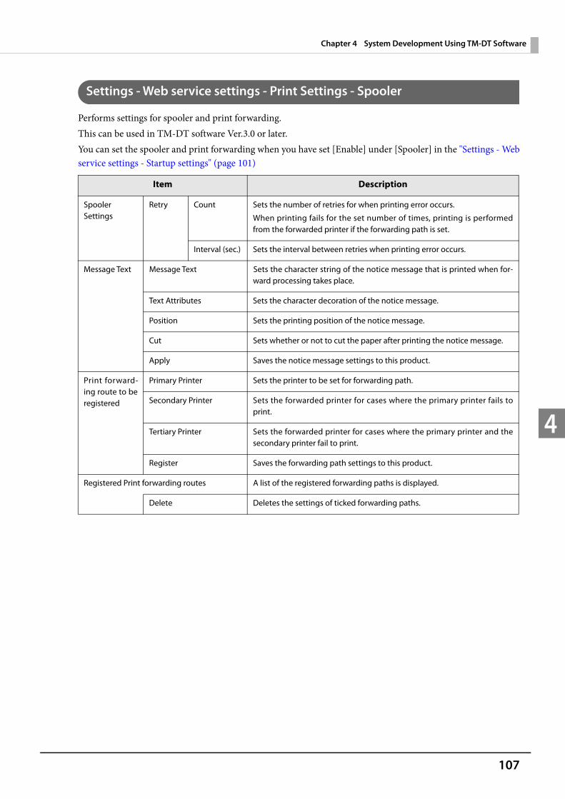
107
Chapter 4 System Development Using TM-DT Software
4
Settings - Web service settings - Print Settings - Spooler
Performs settings for spooler and print forwarding.This can be used in TM-DT software Ver.3.0 or later.You can set the spooler and print forwarding when you have set [Enable] under [Spooler] in the "Settings - Web service settings - Startup settings" (page 101)
Item Description
Spooler Settings
Retry Count Sets the number of retries for when printing error occurs.
When printing fails for the set number of times, printing is performed from the forwarded printer if the forwarding path is set.
Interval (sec.) Sets the interval between retries when printing error occurs.
Message Text Message Text Sets the character string of the notice message that is printed when for-ward processing takes place.
Text Attributes Sets the character decoration of the notice message.
Position Sets the printing position of the notice message.
Cut Sets whether or not to cut the paper after printing the notice message.
Apply Saves the notice message settings to this product.
Print forward-ing route to be registered
Primary Printer Sets the printer to be set for forwarding path.
Secondary Printer Sets the forwarded printer for cases where the primary printer fails to print.
Tertiary Printer Sets the forwarded printer for cases where the primary printer and the secondary printer fail to print.
Register Saves the forwarding path settings to this product.
Registered Print forwarding routes A list of the registered forwarding paths is displayed.
Delete Deletes the settings of ticked forwarding paths.

108
Chapter 4 System Development Using TM-DT Software
4
Settings - Web Service settings - Web Content - Update settings
Performs settings for the installation method and update settings for the Web content registered on this prod-uct.You can set the automatic update when you have set [Enable] under [Automatic update of web content] in the "Settings - Web service settings - Startup settings" (page 101) .
This can be used in TM-DT software Ver.3.0 or later.
Item Description
Automatic update settings
Update schedule Set the schedule for automatic update of the Web content.
ID Sets ID for identifying this product at the Web server.
This ID will be the user ID used for Digest authentication. This set value will also be passed as an ID parameter value for the form data posted to the server.
Password Sets password used for Digest authentication.
File URL Specify a URL for the file to automatically update.
After designating it, click "Access test" and check if the URL is properly specified.
Server Authentication Sets whether or not to conduct server authentication based on the regis-tered certificate when conducting access by https.
Apply Registers the automatic update settings on this product.
After setting settings, update Web content immediately
After the automatic update settings are registered on this product, the Web content will be updated.
Manual update Web content file (*.zip)
Specify the Web content to be installed.
Upload Uploads the specified Web content.
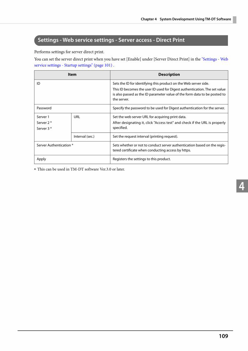
109
Chapter 4 System Development Using TM-DT Software
4
Settings - Web service settings - Server access - Direct Print
Performs settings for server direct print.You can set the server direct print when you have set [Enable] under [Server Direct Print] in the "Settings - Web service settings - Startup settings" (page 101) .
This can be used in TM-DT software Ver.3.0 or later.
Item Description
ID Sets the ID for identifying this product on the Web server side.
This ID becomes the user ID used for Digest authentication. The set value is also passed as the ID parameter value of the form data to be posted to the server.
Password Specify the password to be used for Digest authentication for the server.
Server 1
Server 2 *
Server 3 *
URL Set the web server URL for acquiring print data.
After designating it, click "Access test" and check if the URL is properly specified.
Interval (sec.) Set the request interval (printing request).
Server Authentication * Sets whether or not to conduct server authentication based on the regis-tered certificate when conducting access by https.
Apply Registers the settings to this product.
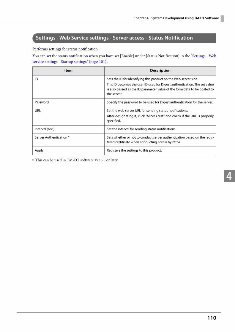
110
Chapter 4 System Development Using TM-DT Software
4
Settings - Web Service settings - Server access - Status Notification
Performs settings for status notification.You can set the status notification when you have set [Enable] under [Status Notification] in the "Settings - Web service settings - Startup settings" (page 101) .
This can be used in TM-DT software Ver.3.0 or later.
Item Description
ID Sets the ID for identifying this product on the Web server side.
This ID becomes the user ID used for Digest authentication. The set value is also passed as the ID parameter value of the form data to be posted to the server.
Password Specify the password to be used for Digest authentication for the server.
URL Set the web server URL for sending status notifications.
After designating it, click "Access test" and check if the URL is properly specified.
Interval (sec.) Set the interval for sending status notifications.
Server Authentication * Sets whether or not to conduct server authentication based on the regis-tered certificate when conducting access by https.
Apply Registers the settings to this product.
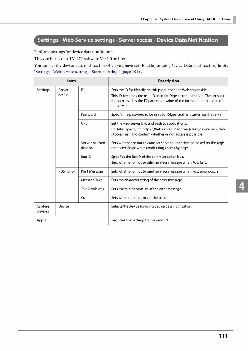
111
Chapter 4 System Development Using TM-DT Software
4
Settings - Web Service settings - Server access - Device Data Notification
Performs settings for device data notification.This can be used in TM-DT software Ver.3.0 or later.You can set the device data notification when you have set [Enable] under [Device Data Notification] in the "Settings - Web service settings - Startup settings" (page 101) .
Item Description
Settings Server access
ID Sets the ID for identifying this product on the Web server side.
This ID becomes the user ID used for Digest authentication. The set value is also passed as the ID parameter value of the form data to be posted to the server.
Password Specify the password to be used for Digest authentication for the server.
URL Set the web server URL and path to applications.
Ex: After specifying http://[Web server IP address]/Test_device.php, click [Access Test] and confirm whether or not access is possible.
Server Authen-tication
Sets whether or not to conduct server authentication based on the regis-tered certificate when conducting access by https.
Box ID Specifies the BoxID of the communication box.
Sets whether or not to print an error message when Post fails.
POST Error Print Message Sets whether or not to print an error message when Post error occurs.
Message Text Sets the character string of the error message.
Text Attributes Sets the text decoration of the error message.
Cut Sets whether or not to cut the paper.
Capture Devices
Device Selects the device for using device data notification.
Apply Registers the settings to this product.

112
Chapter 4 System Development Using TM-DT Software
4
Settings - System settings - Network - Wired LAN - TCP/IP
Sets the IP address, etc. of this product's cable LAN.
This can be used in TM-DT software Ver.3.0 or later.
Item Description
Get IP Address Sets the method of getting the IP address.
IP Address Sets the IP address when [Get IP Address] is set to [Manual].
Subnet Mask Sets the subnet mask when [Get IP Address] is set to [Manual].
Default Gateway Sets the default gateway when [Get IP Address] is set to [Manual].
Acquire DNS Server Address Automatically
Sets the method of getting the address of the DNS server when [Get IP Address] is set to [Manual].
DNS Server Address(in order of use) Sets the addresses of the DNS server in order of usage when [Acquire DNS Server Address Automatically] is set to [Disable].
Print IP Address * When this setting is [Enable], if [Get IP Address] is set to [Auto], the IP address is printed when it is acquired.
Apply Registers the settings to this product.

113
Chapter 4 System Development Using TM-DT Software
4
Settings - System settings - Network - Wireless LAN
Performs settings for a wireless LAN network when the optional wireless LAN cable set (OT-WL01) is used.
Item Description
SSID Sets the SSID.
If you want to set an optional SSID, select [ Input directly ] and set the optional SSID. ASCII characters including space characters can be used for the SSID.
If using an existing SSID, select [ Select from the list ] and configure an optional SSID from the list.
Network mode Sets this product's network mode.
Authentication Method Sets the authentication algorithm.
In the initial settings, the authentication system is set to Open System. For security reasons, use this product after first changing the setting.
Security Mode Sets the encryption algorithm.
In the initial settings, the encryption system is set to None. For security reasons, use this product after first changing the setting.
Default WEP Key Sets the WEP key to use.
WEP key Sets the WEP key.
ASCII characters including space characters can be used for the WEP key.
WPA/WPA2 Pre-Shared Key Enter the pass phrase of the pre-shared key when [Security mode] is set to "WPA" or "WPA2".
ASCII characters including space characters can be used for the pre-shared key.
Apply Registers the settings to this product.
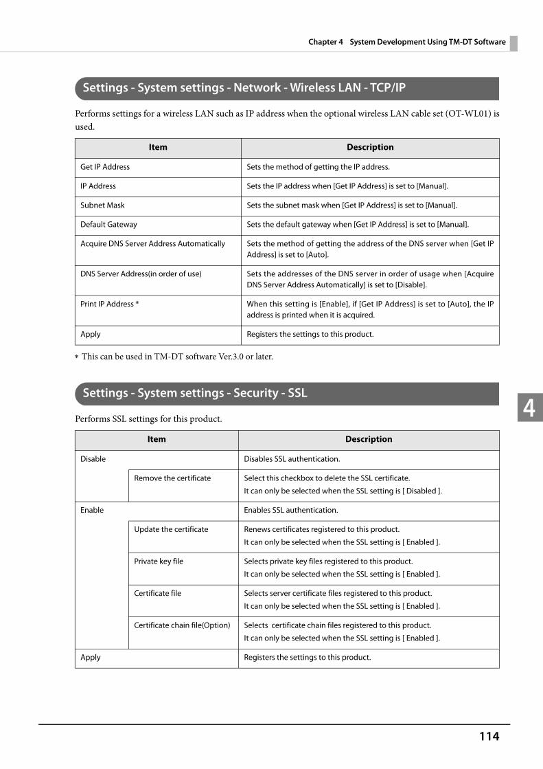
114
Chapter 4 System Development Using TM-DT Software
4
Settings - System settings - Network - Wireless LAN - TCP/IP
Performs settings for a wireless LAN such as IP address when the optional wireless LAN cable set (OT-WL01) is used.
This can be used in TM-DT software Ver.3.0 or later.
Settings - System settings - Security - SSL
Performs SSL settings for this product.
Item Description
Get IP Address Sets the method of getting the IP address.
IP Address Sets the IP address when [Get IP Address] is set to [Manual].
Subnet Mask Sets the subnet mask when [Get IP Address] is set to [Manual].
Default Gateway Sets the default gateway when [Get IP Address] is set to [Manual].
Acquire DNS Server Address Automatically Sets the method of getting the address of the DNS server when [Get IP Address] is set to [Auto].
DNS Server Address(in order of use) Sets the addresses of the DNS server in order of usage when [Acquire DNS Server Address Automatically] is set to [Disable].
Print IP Address * When this setting is [Enable], if [Get IP Address] is set to [Auto], the IP address is printed when it is acquired.
Apply Registers the settings to this product.
Item Description
Disable Disables SSL authentication.
Remove the certificate Select this checkbox to delete the SSL certificate.
It can only be selected when the SSL setting is [ Disabled ].
Enable Enables SSL authentication.
Update the certificate Renews certificates registered to this product.
It can only be selected when the SSL setting is [ Enabled ].
Private key file Selects private key files registered to this product.
It can only be selected when the SSL setting is [ Enabled ].
Certificate file Selects server certificate files registered to this product.
It can only be selected when the SSL setting is [ Enabled ].
Certificate chain file(Option) Selects certificate chain files registered to this product.
It can only be selected when the SSL setting is [ Enabled ].
Apply Registers the settings to this product.
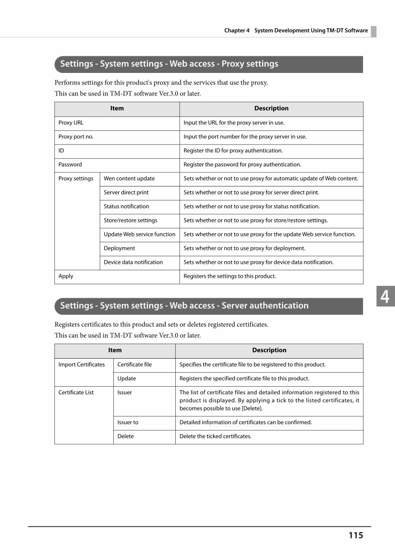
115
Chapter 4 System Development Using TM-DT Software
4
Settings - System settings - Web access - Proxy settings
Performs settings for this product's proxy and the services that use the proxy.This can be used in TM-DT software Ver.3.0 or later.
Settings - System settings - Web access - Server authentication
Registers certificates to this product and sets or deletes registered certificates.This can be used in TM-DT software Ver.3.0 or later.
Item Description
Proxy URL Input the URL for the proxy server in use.
Proxy port no. Input the port number for the proxy server in use.
ID Register the ID for proxy authentication.
Password Register the password for proxy authentication.
Proxy settings Wen content update Sets whether or not to use proxy for automatic update of Web content.
Server direct print Sets whether or not to use proxy for server direct print.
Status notification Sets whether or not to use proxy for status notification.
Store/restore settings Sets whether or not to use proxy for store/restore settings.
Update Web service function Sets whether or not to use proxy for the update Web service function.
Deployment Sets whether or not to use proxy for deployment.
Device data notification Sets whether or not to use proxy for device data notification.
Apply Registers the settings to this product.
Item Description
Import Certificates Certificate file Specifies the certificate file to be registered to this product.
Update Registers the specified certificate file to this product.
Certificate List Issuer The list of certificate files and detailed information registered to this product is displayed. By applying a tick to the listed certificates, it becomes possible to use [Delete].
Issuer to Detailed information of certificates can be confirmed.
Delete Delete the ticked certificates.

116
Chapter 4 System Development Using TM-DT Software
4
Settings - System settings - Access Point - Software access point settings
These settings are performed when using the cable LAN cable set (OT-WL01) as the software access point.This function can be used with Windows Embedded POSReady 7 OS and TM-DT software of Ver. 3.0 or later.
Settings - System settings - Date and time - Time settings
Performs time settings for this product.
Item Description
Disable Renders the software access point invalid.
Enable Validates the software access point.
SSID Enter the software access point password.
The initial setting is below.
TM-DT-<product’s serial number>
Password Register the software access point password.
This is not configured in the default settings. In this case, this product automatically generates and prints a password.
Apply Registers the settings to this product.
Item Description
Date and time Sets the time and date.
Time Zone Sets the area. Sets the time difference from Coordinated Universal Time.
Automatically adjust clock for Daylight Saving Time
Selects whether to automatically adjust the clock for Daylight Saving Time.
Use Time Server Selects whether to use a time server.
Time Server Specifies the URL for the time server.
Apply Registers the settings to this product.
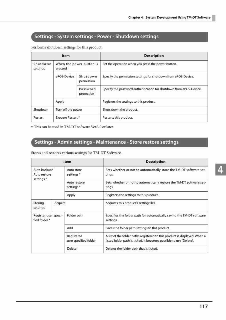
117
Chapter 4 System Development Using TM-DT Software
4
Settings - System settings - Power - Shutdown settings
Performs shutdown settings for this product.
This can be used in TM-DT software Ver.3.0 or later.
Settings - Admin settings - Maintenance - Store restore settings
Stores and restores various settings for TM-DT Software.
Item Description
S h u t d o w n settings
When the power button is pressed
Set the operation when you press the power button.
ePOS-Device S h u t d o w n permission
Specify the permission settings for shutdown from ePOS-Device.
Pa s s w o r d protection
Specify the password authentication for shutdown from ePOS-Device.
Apply Registers the settings to this product.
Shutdown Turn off the power Shuts down the product.
Restart Execute Restart * Restarts this product.
Item Description
Auto backup/Auto restore settings *
Auto store settings *
Sets whether or not to automatically store the TM-DT software set-tings.
Auto restore settings *
Sets whether or not to automatically restore the TM-DT software set-tings.
Apply Registers the settings to this product.
Storing settings
Acquire Acquires this product's setting files.
Register user speci-fied folder *
Folder path Specifies the folder path for automatically saving the TM-DT software settings.
Add Saves the folder path settings to this product.
Registered user specified folder
A list of the folder paths registered to this product is displayed. When a listed folder path is ticked, it becomes possible to use [Delete].
Delete Deletes the folder path that is ticked.

118
Chapter 4 System Development Using TM-DT Software
4 This can be used in TM-DT software Ver.3.0 or later.
Restoring the settings
Specify a local file Select this when recovering this product using locally saved setting files.
Setting file Specifies the setting files for restoring the TM-DT software settings.
If you want to restore setting files on an optional file path, select [Input directly] and specify the optional file path.
If you want to restore this product's settings using the setting files in the [User specified folder], select [Select from the list] and specify an optional setting file from the list.
Specify a file URL Select when restoring this product using a setting files stored on a Web server.
ID * Sets the ID for identifying the setting file for restoring the TM-DT soft-ware settings on the Web server side.
This ID becomes the user ID used for Digest authentication. The set value is also passed as the ID parameter value of the form data to be posted to the server.
Password * Specify the password to be used for Digest authentication for the server.
Setting file URL Set the web server URL and path to applications.
Ex: After specifying http://[Web server IP address]/Test_device.php, click [Access Test] and confirm whether or not access is possible.
Server Authentication * Sets whether or not to conduct server authentication based on the registered certificate when conducting access by https.
Restore Restores the product from the specified setting file.
Save URL settings Saves the setting file URL settings.
Item Description
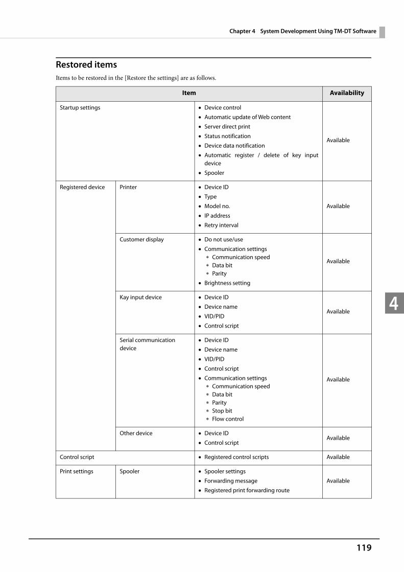
119
Chapter 4 System Development Using TM-DT Software
4
Restored itemsItems to be restored in the [Restore the settings] are as follows.
Item Availability
Startup settings Device control
Automatic update of Web content
Server direct print
Status notification
Device data notification
Automatic register / delete of key input device
Spooler
Available
Registered device Printer Device ID
Type
Model no.
IP address
Retry interval
Available
Customer display Do not use/use
Communication settings Communication speed Data bit Parity
Brightness setting
Available
Kay input device Device ID
Device name
VID/PID
Control script
Available
Serial communication device
Device ID
Device name
VID/PID
Control script
Communication settings Communication speed Data bit Parity Stop bit Flow control
Available
Other device Device ID
Control scriptAvailable
Control script Registered control scripts Available
Print settings Spooler Spooler settings
Forwarding message
Registered print forwarding route
Available
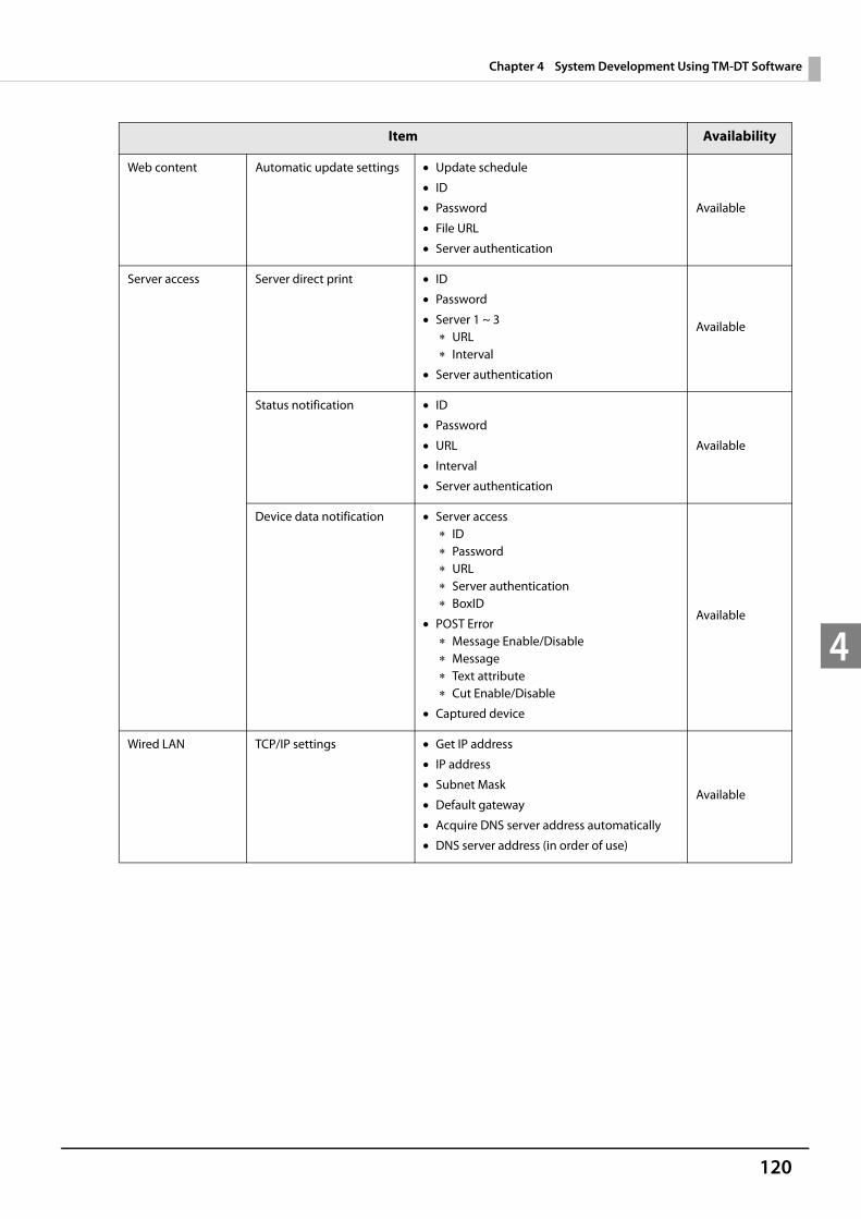
120
Chapter 4 System Development Using TM-DT Software
4
Web content Automatic update settings Update schedule
ID
Password
File URL
Server authentication
Available
Server access Server direct print ID
Password
Server 1 ~ 3 URL Interval
Server authentication
Available
Status notification ID
Password
URL
Interval
Server authentication
Available
Device data notification Server access ID Password URL Server authentication BoxID
POST Error Message Enable/Disable Message Text attribute Cut Enable/Disable
Captured device
Available
Wired LAN TCP/IP settings Get IP address
IP address
Subnet Mask
Default gateway
Acquire DNS server address automatically
DNS server address (in order of use)
Available
Item Availability
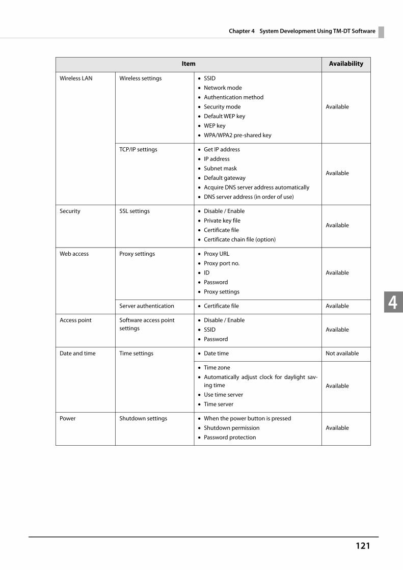
121
Chapter 4 System Development Using TM-DT Software
4
Wireless LAN Wireless settings SSID
Network mode
Authentication method
Security mode
Default WEP key
WEP key
WPA/WPA2 pre-shared key
Available
TCP/IP settings Get IP address
IP address
Subnet mask
Default gateway
Acquire DNS server address automatically
DNS server address (in order of use)
Available
Security SSL settings Disable / Enable
Private key file
Certificate file
Certificate chain file (option)
Available
Web access Proxy settings Proxy URL
Proxy port no.
ID
Password
Proxy settings
Available
Server authentication Certificate file Available
Access point Software access point settings
Disable / Enable
SSID
Password
Available
Date and time Time settings Date time Not available
Time zone
Automatically adjust clock for daylight sav-ing time
Use time server
Time server
Available
Power Shutdown settings When the power button is pressed
Shutdown permission
Password protection
Available
Item Availability
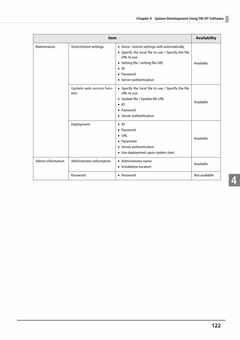
122
Chapter 4 System Development Using TM-DT Software
4
Maintenance Store/restore settings Store / restore settings with automatically
Specify the local file to use / Specify the file URL to use
Setting file / setting file URL
ID
Password
Server authentication
Available
Update web service func-tion
Specify the local file to use / Specify the file URL to use
Update file / Update file URL
ID
Password
Server authentication
Available
Deployment ID
Password
URL
Parameter
Server authentication
Use deployment upon system start
Available
Admin information Administrator information Administrator name
Installation locationAvailable
Password Password Not available
Item Availability
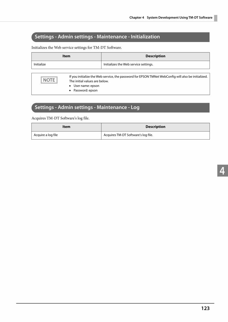
123
Chapter 4 System Development Using TM-DT Software
4
Settings - Admin settings - Maintenance - Initialization
Initializes the Web service settings for TM-DT Software.
Settings - Admin settings - Maintenance - Log
Acquires TM-DT Software's log file.
Item Description
Initialize Initializes the Web service settings.
If you initialize the Web service, the password for EPSON TMNet WebConfig will also be initialized. The initial values are below. User name: epson Password: epson
Item Description
Acquire a log file Acquires TM-DT Software's log file.

124
Chapter 4 System Development Using TM-DT Software
4
Settings - Admin settings - Maintenance - Update Web service function
Updates and sets the Web service function of TM-DT Software.The latest version TM-DT software can be used through renewing the Web service functions.
This can be used in TM-DT software Ver.3.0 or later.
Item Description
Specify a local file Select when updating the Web service using a locally saved update file.
Update file Specify the URL of the file for updating.
Specify a file URL Select when updating the Web service using an update file saved on the Web server.
ID * Sets the ID for identifying the renewal file on the Web server side.
This ID becomes the user ID used for Digest authentication. The set value is also passed as the ID parameter value of the form data to be posted to the server.
Password * Sets the password used in Digest authentication.
Update file URL Specify the Web server URL and path to the application.
Ex: Specify http://[Web server's IP address]/[For updating file name], then click [Access test] to confirm that access is possible.
Server authentication *
Sets whether or not to conduct server authentication based on the regis-tered certificate when conducting access by https.
Update Updates the Web service functions using the specified update file.
Save URL settings Saves the [Specify a file URL] setting to this product.

125
Chapter 4 System Development Using TM-DT Software
4
Settings - Admin settings - Maintenance - Deployment
Sets the deployment for downloading and updating the TM-DT software, etc. setting files from the HTTP server.This can be used in TM-DT software Ver.3.0 or later.
Settings - Admin settings - Admin information - Admin information
Sets the administrator information for TM-DT Software.
Item Description
ID Sets the ID for identifying this product on the Web server side. This ID becomes the user ID used in Digest authentication.
The set value is also passed as the ID parameter value of the form data to be posted to the server.
Password Sets the password used in Digest authentication.
URL Specify the Web server URL and path to the application.
Ex: Specify http://[Web server's IP address]/[Setting file name], then click [Access test] to confirm that access is possible.
Parameter Specifies the user specified information that is passed to the HTTP server.
Server authentication Sets whether or not to conduct server authentication based on the regis-tered certificate when conducting access by https.
Use deployment upon system start Sets whether or not to conduct deployment when starting this product.
Apply Save the deployment settings to this product.
After applying settings, start deployment immediately
After saving the deployment settings to this product, execute deploy-ment.
Item Description
Administrator name Set the administrator name.
Installation location Set the installation location.
Apply Registers the settings to this product.

126
Chapter 4 System Development Using TM-DT Software
4
Settings - Admin settings - Admin information - Password
Sets the password for launch for EPSON TMNet Webconfig.
Item Description
Old password Input the current password.
New password Input the new password.
New password (Reenter confirm For confirmation, input the new password again.
Apply Registers the set password on this product.
The initial setting of user name and password for EPSON TMNet Webconfig are following.User name: epsonPassword: epson
Cannot change the user name
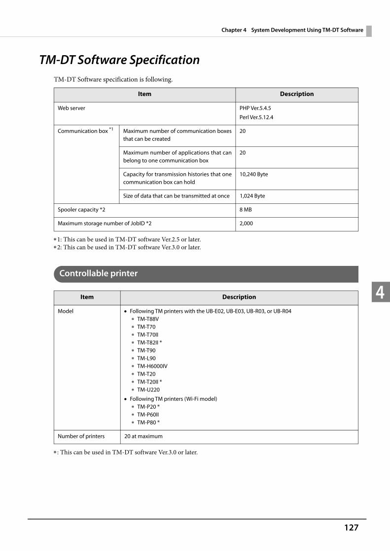
127
Chapter 4 System Development Using TM-DT Software
4
TM-DT Software SpecificationTM-DT Software specification is following.
1: This can be used in TM-DT software Ver.2.5 or later.2: This can be used in TM-DT software Ver.3.0 or later.
Controllable printer
: This can be used in TM-DT software Ver.3.0 or later.
Item Description
Web server PHP Ver.5.4.5
Perl Ver.5.12.4
Communication box *1 Maximum number of communication boxes that can be created
20
Maximum number of applications that can belong to one communication box
20
Capacity for transmission histories that one communication box can hold
10,240 Byte
Size of data that can be transmitted at once 1,024 Byte
Spooler capacity *2 8 MB
Maximum storage number of JobID *2 2,000
Item Description
Model Following TM printers with the UB-E02, UB-E03, UB-R03, or UB-R04 TM-T88V TM-T70 TM-T70II TM-T82II * TM-T90 TM-L90 TM-H6000IV TM-T20 TM-T20II * TM-U220
Following TM printers (Wi-Fi model) TM-P20 * TM-P60II TM-P80 *
Number of printers 20 at maximum
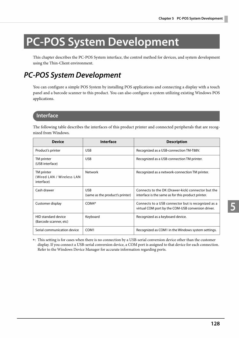
128
Chapter 5 PC-POS System Development
5
PC-POS System DevelopmentThis chapter describes the PC-POS System interface, the control method for devices, and system development using the Thin-Client environment.
PC-POS System DevelopmentYou can configure a simple POS System by installing POS applications and connecting a display with a touch panel and a barcode scanner to this product. You can also configure a system utilizing existing Windows POS applications.
Interface
The following table describes the interfaces of this product printer and connected peripherals that are recog-nized from Windows.
: This setting is for cases when there is no connection by a USB-serial conversion device other than the customer display. If you connect a USB-serial conversion device, a COM port is assigned to that device for each connection. Refer to the Windows Device Manager for accurate information regarding ports.
Device Interface Description
Product’s printer USB Recognized as a USB-connection TM-T88V.
TM printer(USB interface)
USB Recognized as a USB-connection TM printer.
TM printer( Wired LAN / Wireless LAN interface)
Network Recognized as a network-connection TM printer.
Cash drawer USB (same as the product’s printer)
Connects to the DK (Drawer-kick) connector but the interface is the same as for this product printer.
Customer display COM4* Connects to a USB connector but is recognized as a virtual COM port by the COM-USB conversion driver.
HID standard device(Barcode scanner, etc)
Keyboard Recognized as a keyboard device.
Serial communication device COM1 Recognized as COM1 in the Windows system settings.
129
Chapter 5 PC-POS System Development
5
How to Control Peripherals
Printer
This product's printer and the Epson TM printer are controlled by ESC/POS commands.
The user can control the printer by using the ESC/POS command or the following development kit and driver. EPSON OPOS ADK EPSON OPOS ADK for .NET EPSON JavaPOS ADK EPSON Advanced Printer Driver Ver.5 EPSON Advanced Printer Driver Ver.4
Cash drawer
The cash drawer control commands are incorporated into the printer's ESC/POS commands. The driver and development kit can use the same ones as the printer.
Customer display
The customer display is controlled by ESC/POS commands.
The user can control the customer display by using the ESC/POS command or the following development kit and driver. EPSON OPOS ADK EPSON OPOS ADK for .NET EPSON JavaPOS ADK EPSON Advanced Printer Driver Ver.4
Other devices
HID Standard DeviceThis Windows standard driver is recognized as a keyboard device.
Serial Communication DeviceThis is recognized as a Windows serial communication device. When dedicated drivers are prepared for each device, they can be controlled by the drivers. For details, see each device manual.
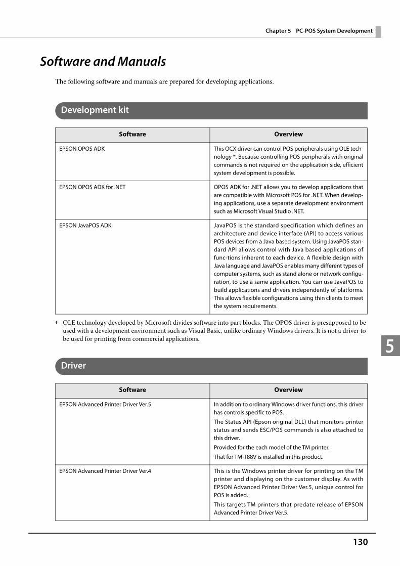
130
Chapter 5 PC-POS System Development
5
Software and ManualsThe following software and manuals are prepared for developing applications.
Development kit
OLE technology developed by Microsoft divides software into part blocks. The OPOS driver is presupposed to be used with a development environment such as Visual Basic, unlike ordinary Windows drivers. It is not a driver to be used for printing from commercial applications.
Driver
Software Overview
EPSON OPOS ADK This OCX driver can control POS peripherals using OLE tech-nology *. Because controlling POS peripherals with original commands is not required on the application side, efficient system development is possible.
EPSON OPOS ADK for .NET OPOS ADK for .NET allows you to develop applications that are compatible with Microsoft POS for .NET. When develop-ing applications, use a separate development environment such as Microsoft Visual Studio .NET.
EPSON JavaPOS ADK JavaPOS is the standard specification which defines an architecture and device interface (API) to access various POS devices from a Java based system. Using JavaPOS stan-dard API allows control with Java based applications of func-tions inherent to each device. A flexible design with Java language and JavaPOS enables many different types of computer systems, such as stand alone or network configu-ration, to use a same application. You can use JavaPOS to build applications and drivers independently of platforms. This allows flexible configurations using thin clients to meet the system requirements.
Software Overview
EPSON Advanced Printer Driver Ver.5 In addition to ordinary Windows driver functions, this driver has controls specific to POS.
The Status API (Epson original DLL) that monitors printer status and sends ESC/POS commands is also attached to this driver.
Provided for the each model of the TM printer.
That for TM-T88V is installed in this product.
EPSON Advanced Printer Driver Ver.4 This is the Windows printer driver for printing on the TM printer and displaying on the customer display. As with EPSON Advanced Printer Driver Ver.5, unique control for POS is added.
This targets TM printers that predate release of EPSON Advanced Printer Driver Ver.5.

131
Chapter 5 PC-POS System Development
5
Utility
Others
Software Overview
TM-T88V Utility This utility is for confirming and changing printer settings. It is already installed in this product.
TM-DT Thin-Client System Setup Tool This tool supports configuration of the Thin-Client system.
IP Address Setting Tool This tool is for setting the client's (this product's) IP address on the Thin-Client system server side.
Manual Overview
ESC/POS Command Reference ESC/POS is the command system for the Epson original printer and customer display. With ESC/POS commands, you can directly control all the TM printer functions, but detailed knowledge of printer specifications or combination of com-mands is required, compared to using a driver.
For details, see ESC/POS Command Reference.
https://reference.epson-biz.com/modules/ref_escpos/
The ESC/POS commands for the customer displays are described in the product specifications for the respective customer displays.
The ESC/POS commands for the customer displays are detailed in the product specifications for the respective cus-tomer displays. You must sign a non-disclosure agreement with our company to obtain the product specifications. Contact your local distributor for more information.
132
Chapter 5 PC-POS System Development
5
System Development using the Thin-Client EnvironmentYou can configure a Thin-Client system utilizing the Windows PC-POS System. The Thin-Client solutions provided by each company are used in system configuration.For details, see the "TM-DT Thin-Client System Setup Guide".
Desktop Virtualization
Desktop virtualization is a system that virtualizes the entire OS client desktop. The OS desktop screen executed on the server is transferred to the client, and the user operates the virtual desktop to execute applications.
Control of Peripherals Printer, cash drawer, customer display:
Control is performed through communication between the Epson communication modules mounted on the guest OS and client.
HID device:Client's Windows standard driver is recognized as a keyboard device.
Application Virtualization
Application virtualization refers to virtualized systems for each application. The user executes without installing applications in the client OS. There are two methods for application virtualization. The virtualized applications are distributed and executed by the client, or the application screen executed in the server is transferred to the client and operated.
Control of PeripheralsThe control method differs according to the method of application virtualization.
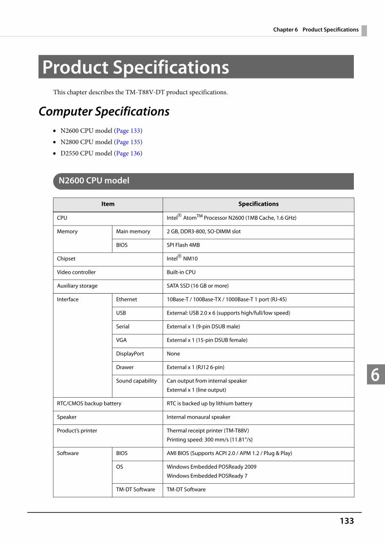
133
Chapter 6 Product Specifications
6
Product SpecificationsThis chapter describes the TM-T88V-DT product specifications.
Computer Specifications N2600 CPU model (Page 133) N2800 CPU model (Page 135) D2550 CPU model (Page 136)
N2600 CPU model
Item Specifications
CPU Intel AtomTM Processor N2600 (1MB Cache, 1.6 GHz)
Memory Main memory 2 GB, DDR3-800, SO-DIMM slot
BIOS SPI Flash 4MB
Chipset Intel NM10
Video controller Built-in CPU
Auxiliary storage SATA SSD (16 GB or more)
Interface Ethernet 10Base-T / 100Base-TX / 1000Base-T 1 port (RJ-45)
USB External: USB 2.0 x 6 (supports high/full/low speed)
Serial External x 1 (9-pin DSUB male)
VGA External x 1 (15-pin DSUB female)
DisplayPort None
Drawer External x 1 (RJ12 6-pin)
Sound capability Can output from internal speaker
External x 1 (line output)
RTC/CMOS backup battery RTC is backed up by lithium battery
Speaker Internal monaural speaker
Product’s printer Thermal receipt printer (TM-T88V)
Printing speed: 300 mm/s {11.81”/s}
Software BIOS AMI BIOS (Supports ACPI 2.0 / APM 1.2 / Plug & Play)
OS Windows Embedded POSReady 2009
Windows Embedded POSReady 7
TM-DT Software TM-DT Software
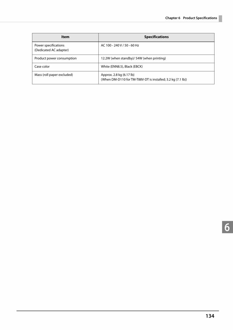
134
Chapter 6 Product Specifications
6
Power specifications(Dedicated AC adapter)
AC 100 - 240 V / 50 - 60 Hz
Product power consumption 12.2W (when standby)/ 54W (when printing)
Case color White (ENN8.5), Black (EBCK)
Mass (roll paper excluded) Approx. 2.8 kg {6.17 lb}(When DM-D110 for TM-T88V-DT is installed; 3.2 kg {7.1 lb})
Item Specifications
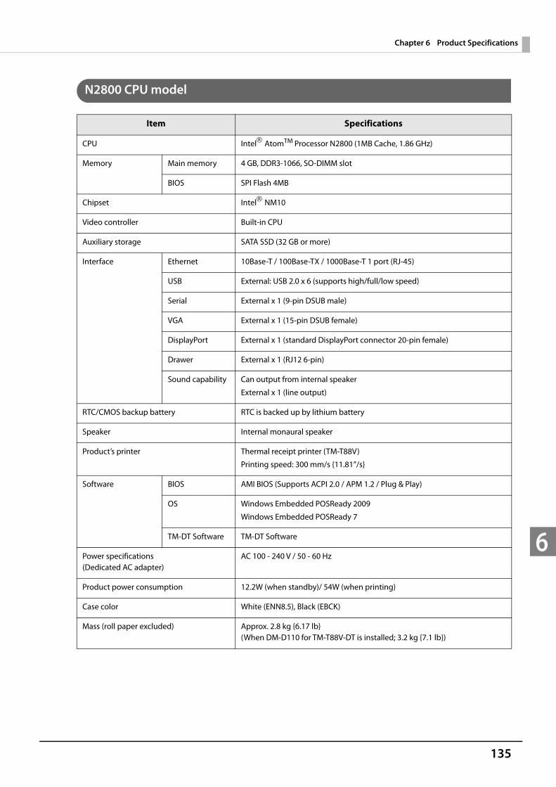
135
Chapter 6 Product Specifications
6
N2800 CPU model
Item Specifications
CPU Intel AtomTM Processor N2800 (1MB Cache, 1.86 GHz)
Memory Main memory 4 GB, DDR3-1066, SO-DIMM slot
BIOS SPI Flash 4MB
Chipset Intel NM10
Video controller Built-in CPU
Auxiliary storage SATA SSD (32 GB or more)
Interface Ethernet 10Base-T / 100Base-TX / 1000Base-T 1 port (RJ-45)
USB External: USB 2.0 x 6 (supports high/full/low speed)
Serial External x 1 (9-pin DSUB male)
VGA External x 1 (15-pin DSUB female)
DisplayPort External x 1 (standard DisplayPort connector 20-pin female)
Drawer External x 1 (RJ12 6-pin)
Sound capability Can output from internal speaker
External x 1 (line output)
RTC/CMOS backup battery RTC is backed up by lithium battery
Speaker Internal monaural speaker
Product’s printer Thermal receipt printer (TM-T88V)
Printing speed: 300 mm/s {11.81”/s}
Software BIOS AMI BIOS (Supports ACPI 2.0 / APM 1.2 / Plug & Play)
OS Windows Embedded POSReady 2009
Windows Embedded POSReady 7
TM-DT Software TM-DT Software
Power specifications(Dedicated AC adapter)
AC 100 - 240 V / 50 - 60 Hz
Product power consumption 12.2W (when standby)/ 54W (when printing)
Case color White (ENN8.5), Black (EBCK)
Mass (roll paper excluded) Approx. 2.8 kg {6.17 lb}(When DM-D110 for TM-T88V-DT is installed; 3.2 kg {7.1 lb})

136
Chapter 6 Product Specifications
6
D2550 CPU model
Item Specifications
CPU Intel AtomTM D2550 (1MB Cache, 1.86 GHz)
Memory Main memory 4 GB, DDR3-1066, SO-DIMM slot
BIOS SPI Flash 4MB
Chipset Intel NM10
Video controller Built-in CPU
Auxiliary storage SATA HDD (500GB or more) / SATA SSD (32 GB or more)
Interface Ethernet 10Base-T / 100Base-TX / 1000Base-T 1 port (RJ-45)
USB External: USB 2.0 x 6 (supports high/full/low speed)
Serial External x 1 (9-pin DSUB male)
VGA External x 1 (15-pin DSUB female)
DisplayPort External x 1 (standard DisplayPort connector 20-pin female)
Drawer External x 1 (RJ12 6-pin)
Sound capability Can output from internal speaker
External x 1 (line output)
RTC/CMOS backup battery RTC is backed up by lithium battery
Speaker Internal monaural speaker
Product’s printer Thermal receipt printer (TM-T88V)
Printing speed: 300 mm/s {11.81”/s}
Software BIOS AMI BIOS (Supports ACPI 2.0 / APM 1.2 / Plug & Play)
OS Windows Embedded POSReady 2009
Windows Embedded POSReady 7
TM-DT Software TM-DT Software
Power specifications(Dedicated AC adapter)
AC 100 - 240 V / 50 - 60 Hz
Product power consumption 12.2W (when standby)/ 54W (when printing)
Case color Black
Mass (roll paper excluded) Approx. 2.8 kg {6.17 lb}(When DM-D110 for TM-T88V-DT is installed; 3.2 kg {7.1 lb})
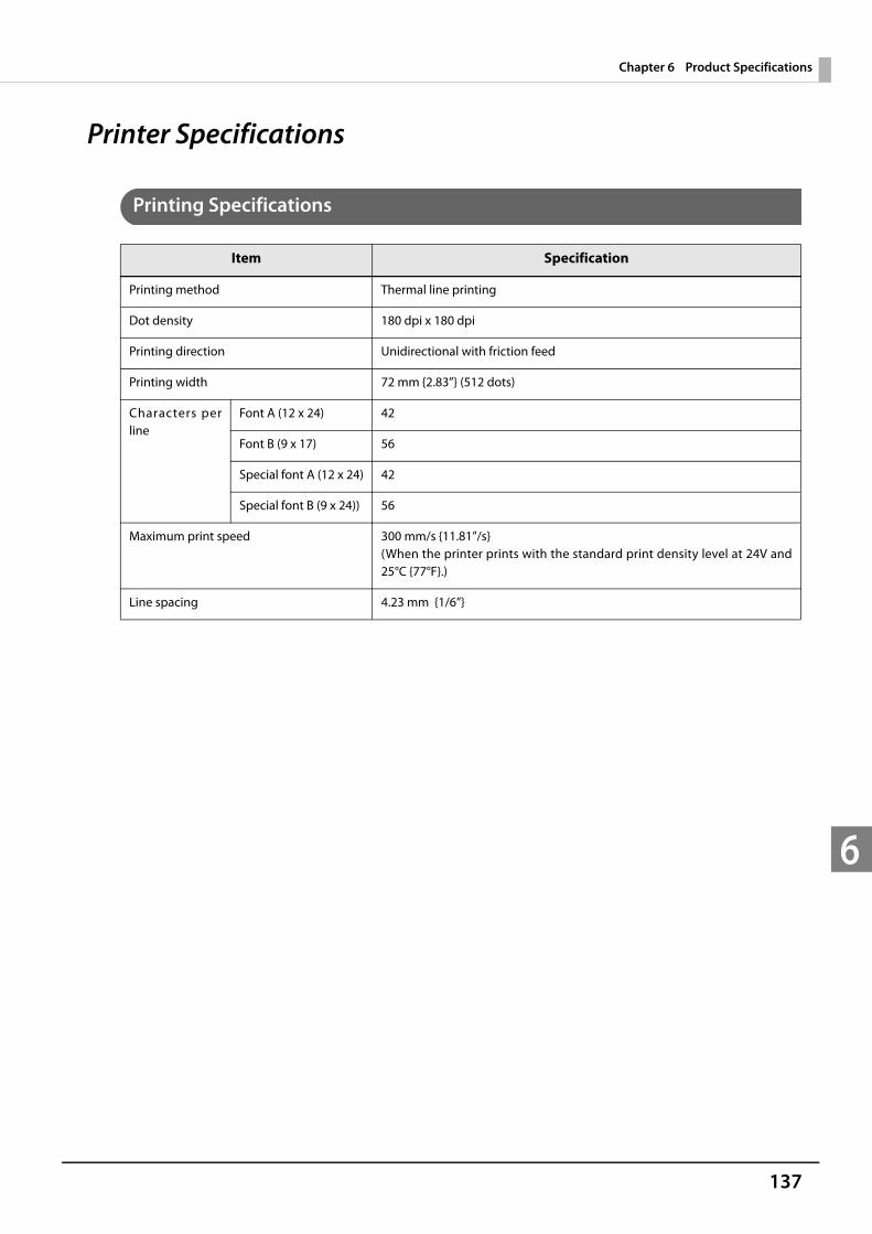
137
Chapter 6 Product Specifications
6
Printer Specifications
Printing Specifications
Item Specification
Printing method Thermal line printing
Dot density 180 dpi x 180 dpi
Printing direction Unidirectional with friction feed
Printing width 72 mm {2.83”} (512 dots)
Characters per line
Font A (12 x 24) 42
Font B (9 x 17) 56
Special font A (12 x 24) 42
Special font B (9 x 24)) 56
Maximum print speed 300 mm/s {11.81”/s} (When the printer prints with the standard print density level at 24V and 25°C {77°F}.)
Line spacing 4.23 mm {1/6”}
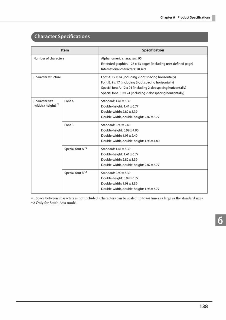
138
Chapter 6 Product Specifications
6
Character Specifications
1 Space between characters is not included. Characters can be scaled up to 64 times as large as the standard sizes.2 Only for South Asia model.
Item Specification
Number of characters Alphanumeric characters: 95
Extended graphics: 128 x 43 pages (including user-defined page)
International characters: 18 sets
Character structure Font A: 12 x 24 (including 2-dot spacing horizontally)
Font B: 9 x 17 (including 2-dot spacing horizontally)
Special font A: 12 x 24 (including 2-dot spacing horizontally)
Special font B: 9 x 24 (including 2-dot spacing horizontally)
Character size(width x height) *1
Font A Standard: 1.41 x 3.39
Double-height: 1.41 x 6.77
Double-width: 2.82 x 3.39
Double-width, double-height: 2.82 x 6.77
Font B Standard: 0.99 x 2.40
Double-height: 0.99 x 4.80
Double-width: 1.98 x 2.40
Double-width, double-height: 1.98 x 4.80
Special font A *2 Standard: 1.41 x 3.39
Double-height: 1.41 x 6.77
Double-width: 2.82 x 3.39
Double-width, double-height: 2.82 x 6.77
Special font B *2 Standard: 0.99 x 3.39
Double-height: 0.99 x 6.77
Double-width: 1.98 x 3.39
Double-width, double-height: 1.98 x 6.77
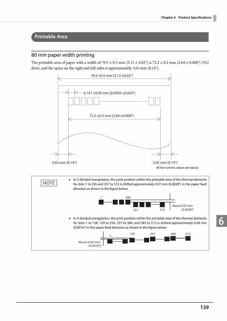
139
Chapter 6 Product Specifications
6
Printable Area
80 mm paper width printingThe printable area of paper with a width of 79.5 ± 0.5 mm {3.13 ± 0.02"} is 72.2 ± 0.2 mm {2.84 ± 0.008"} (512 dots), and the space on the right and left sides is approximately 3.65 mm {0.14"}.
In 2-divided energization, the print position within the printable area of the thermal elements for dots 1 to 256 and 257 to 512 is shifted approximately 0.07 mm {0.0028"} in the paper feed direction as shown in the figure below.
In 4-divided energization, the print position within the printable area of the thermal elements for dots 1 to 128, 129 to 256, 257 to 384, and 385 to 512 is shifted approximately 0.04 mm {0.0016"} in the paper feed direction as shown in the figure below.
0.141 ±0.05 mm {0.0056 ±0.002”}
79.5 ±0.5 mm {3.13 ±0.02”}
72.2 ±0.2 mm {2.84 ±0.008”}
3.65 mm {0.14”} 3.65 mm {0.14”}All the numeric values are typical.
2561
257 512About 0.07 mm {0.0028”}
1291
512385257
About 0.04 mm {0.0016”}
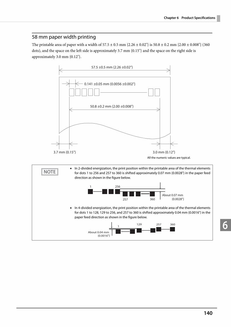
140
Chapter 6 Product Specifications
6
58 mm paper width printingThe printable area of paper with a width of 57.5 ± 0.5 mm {2.26 ± 0.02"} is 50.8 ± 0.2 mm {2.00 ± 0.008"} (360 dots), and the space on the left side is approximately 3.7 mm {0.15"} and the space on the right side is approximately 3.0 mm {0.12"}.
In 2-divided energization, the print position within the printable area of the thermal elements for dots 1 to 256 and 257 to 360 is shifted approximately 0.07 mm {0.0028"} in the paper feed direction as shown in the figure below.
In 4-divided energization, the print position within the printable area of the thermal elements for dots 1 to 128, 129 to 256, and 257 to 360 is shifted approximately 0.04 mm {0.0016"} in the paper feed direction as shown in the figure below.
0.141 ±0.05 mm {0.0056 ±0.002”}
57.5 ±0.5 mm {2.26 ±0.02”}
50.8 ±0.2 mm {2.00 ±0.008”}
3.7 mm {0.15”} 3.0 mm {0.12”}All the numeric values are typical.
2561
257 360About 0.07 mm {0.0028”}
1291
360257
About 0.04 mm {0.0016”}

141
Chapter 6 Product Specifications
6
Printing and Cutting Positions
The values above may vary slightly as a result of paper slack or variations in the paper. Take this into account when setting the cutting position of the autocutter.
Autocutter blade position
Approx. 29 mm {1.14”}
Approx. 15mm {0.059”}
Manual-cutter position
Center of the print dotline
Paper feed direction
Printable area
Last line of the previous receipt
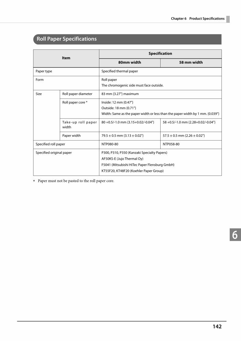
142
Chapter 6 Product Specifications
6
Roll Paper Specifications
Paper must not be pasted to the roll paper core.
ItemSpecification
80mm width 58 mm width
Paper type Specified thermal paper
Form Roll paper
The chromogenic side must face outside.
Size Roll paper diameter 83 mm {3.27"} maximum
Roll paper core * Inside: 12 mm {0.47"}
Outside: 18 mm {0.71"}
Width: Same as the paper width or less than the paper width by 1 mm. {0.039”}
Tak e - up ro l l p aper width
80 +0.5/-1.0 mm {3.15+0.02/-0.04"} 58 +0.5/-1.0 mm {2.28+0.02/-0.04"}
Paper width 79.5 ± 0.5 mm {3.13 ± 0.02"} 57.5 ± 0.5 mm {2.26 ± 0.02"}
Specified roll paper NTP080-80 NTP058-80
Specified original paper P300, P310, P350 (Kanzaki Specialty Papers)
AF50KS-E (Jujo Thermal Oy)
F5041 (Mitsubishi HiTec Paper Flensburg GmbH)
KT55F20, KT48F20 (Koehler Paper Group)

143
Chapter 6 Product Specifications
6
Power supply capacity for external devices
Environmental Conditions
Item Specification
Port Power supply Supply capacity
USB DC +5 V 500 mA each
Drawer DC +24 V 1.0 A
DisplayPort DC +3.3 V 500 mA
Item Specification
Temperature/Humidity
Operating 5 to 40 °C {41 to 104 °F}, 10 to 90%RH (no condensation)
50%
Storage
(paper excluded)
-10 to 50 °C {14 to 122 °F}, 10 to 90%RH (no condensation)
Acoustic noise (operating) Approximately 55 dB (bystander position)
(The values above are measured in the Epson evaluation condition. The acoustic noise varies, depending on the paper used, printing contents, or the setting values, such as print speed or print density.)
34 °C, 90%RH
40 °C, 65%RH
31 °C, 90%RH
Specified original paper other than above
Specified original paper:P300, P310, P350
40 °C, 43%RH
34 °C, 75%RH
[%RH]
[°C]

144
Chapter 6 Product Specifications
6
External Dimensions
TM-T88V-DT (with connector cover) Width: 145 mm {5.71"} Depth: 279 mm {10.98"} (including connector cover) Height: 183 mm {7.20"}
[Units: mm]
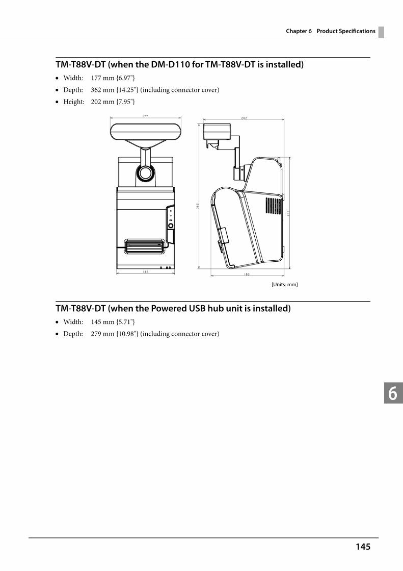
145
Chapter 6 Product Specifications
6
TM-T88V-DT (when the DM-D110 for TM-T88V-DT is installed) Width: 177 mm {6.97"} Depth: 362 mm {14.25"} (including connector cover) Height: 202 mm {7.95"}
TM-T88V-DT (when the Powered USB hub unit is installed) Width: 145 mm {5.71"} Depth: 279 mm {10.98"} (including connector cover)
[Units: mm]
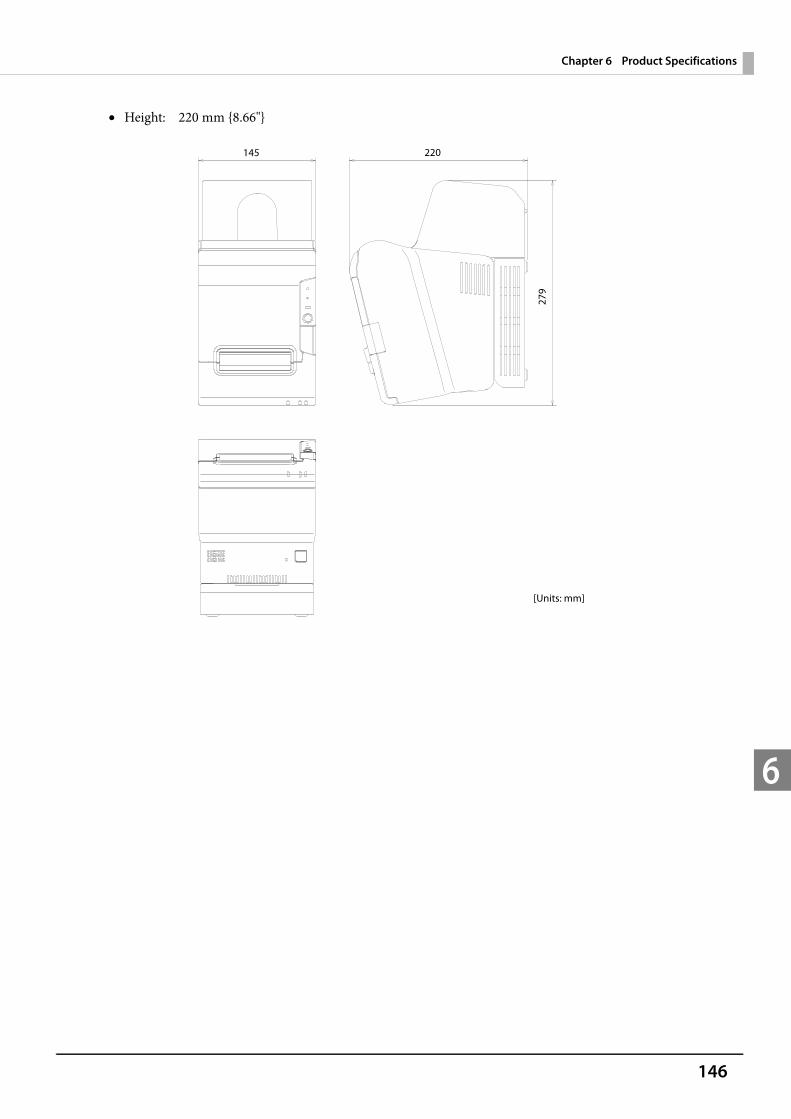
146
Chapter 6 Product Specifications
6
Height: 220 mm {8.66"}
[Units: mm]
145 220
279
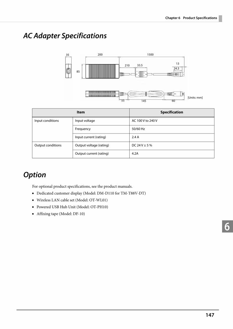
147
Chapter 6 Product Specifications
6
AC Adapter Specifications
OptionFor optional product specifications, see the product manuals. Dedicated customer display (Model: DM-D110 for TM-T88V-DT) Wireless LAN cable set (Model: OT-WL01) Powered USB Hub Unit (Model: OT-PH10) Affixing tape (Model: DF-10)
Item Specification
Input conditions Input voltage AC 100 V to 240 V
Frequency 50/60 Hz
Input current (rating) 2.4 A
Output conditions Output voltage (rating) DC 24 V ± 5 %
Output current (rating) 4.2A
[Units: mm]
35 200 1500
210 33.5 13
24.3
55 145 60
85
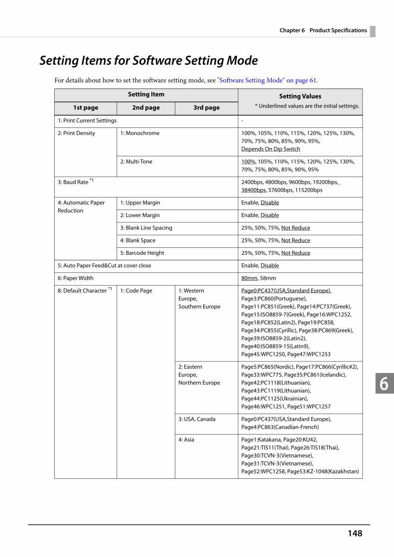
148
Chapter 6 Product Specifications
6
Setting Items for Software Setting ModeFor details about how to set the software setting mode, see "Software Setting Mode" on page 61.
Setting Item Setting Values* Underlined values are the initial settings.1st page 2nd page 3rd page
1: Print Current Settings -
2: Print Density 1: Monochrome 100%, 105%, 110%, 115%, 120%, 125%, 130%, 70%, 75%, 80%, 85%, 90%, 95%, Depends On Dip Switch
2: Multi-Tone 100%, 105%, 110%, 115%, 120%, 125%, 130%, 70%, 75%, 80%, 85%, 90%, 95%
3: Baud Rate *1 2400bps, 4800bps, 9600bps, 19200bps, 38400bps, 57600bps, 115200bps
4: Automatic Paper Reduction
1: Upper Margin Enable, Disable
2: Lower Margin Enable, Disable
3: Blank Line Spacing 25%, 50%, 75%, Not Reduce
4: Blank Space 25%, 50%, 75%, Not Reduce
5: Barcode Height 25%, 50%, 75%, Not Reduce
5: Auto Paper Feed&Cut at cover close Enable, Disable
6: Paper Width 80mm, 58mm
8: Default Character *1 1: Code Page 1: Western Europe, Southern Europe
Page0:PC437(USA,Standard Europe), Page3:PC860(Portuguese), Page11:PC851(Greek), Page14:PC737(Greek), Page15:ISO8859-7(Greek), Page16:WPC1252, Page18:PC852(Latin2), Page19:PC858, Page34:PC855(Cyrillic), Page38:PC869(Greek), Page39:ISO8859-2(Latin2), Page40:ISO8859-15(Latin9), Page45:WPC1250, Page47:WPC1253
2: Eastern Europe, Northern Europe
Page5:PC865(Nordic), Page17:PC866(Cyrillic#2), Page33:WPC775, Page35:PC861(Icelandic), Page42:PC1118(Lithuanian), Page43:PC1119(Lithuanian), Page44:PC1125(Ukrainian), Page46:WPC1251, Page51:WPC1257
3: USA, Canada Page0:PC437(USA,Standard Europe), Page4:PC863(Canadian-French)
4: Asia Page1:Katakana, Page20:KU42, Page21:TIS11(Thai), Page26:TIS18(Thai), Page30:TCVN-3(Vietnamese), Page31:TCVN-3(Vietnamese), Page52:WPC1258, Page53:KZ-1048(Kazakhstan)
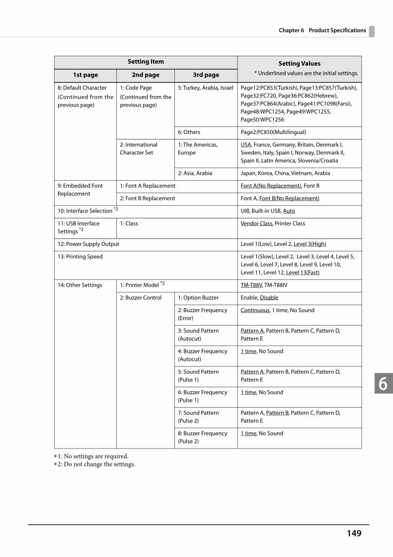
149
Chapter 6 Product Specifications
6
1: No settings are required.2: Do not change the settings.
8: Default Character
(Continued from the previous page)
1: Code Page
(Continued from the previous page)
5: Turkey, Arabia, Israel Page12:PC853(Turkish), Page13:PC857(Turkish), Page32:PC720, Page36:PC862(Hebrew), Page37:PC864(Arabic), Page41:PC1098(Farsi), Page48:WPC1254, Page49:WPC1255, Page50:WPC1256
6: Others Page2:PC850(Multilingual)
2: International Character Set
1: The Americas, Europe
USA, France, Germany, Britain, Denmark I, Sweden, Italy, Spain I, Norway, Denmark II, Spain II, Latin America, Slovenia/Croatia
2: Asia, Arabia Japan, Korea, China, Vietnam, Arabia
9: Embedded Font Replacement
1: Font A Replacement Font A(No Replacement), Font B
2: Font B Replacement Font A, Font B(No Replacement)
10: Interface Selection *2 UIB, Built-in USB, Auto
11: USB Interface Settings *2
1: Class Vendor Class, Printer Class
12: Power Supply Output Level 1(Low), Level 2, Level 3(High)
13: Printing Speed Level 1(Slow), Level 2, Level 3, Level 4, Level 5, Level 6, Level 7, Level 8, Level 9, Level 10, Level 11, Level 12, Level 13(Fast)
14: Other Settings 1: Printer Model *2 TM-T88V, TM-T88IV
2: Buzzer Control 1: Option Buzzer Enable, Disable
2: Buzzer Frequency (Error)
Continuous, 1 time, No Sound
3: Sound Pattern(Autocut)
Pattern A, Pattern B, Pattern C, Pattern D, Pattern E
4: Buzzer Frequency (Autocut)
1 time, No Sound
5: Sound Pattern(Pulse 1)
Pattern A, Pattern B, Pattern C, Pattern D, Pattern E
6: Buzzer Frequency (Pulse 1)
1 time, No Sound
7: Sound Pattern(Pulse 2)
Pattern A, Pattern B, Pattern C, Pattern D, Pattern E
8: Buzzer Frequency(Pulse 2)
1 time, No Sound
Setting Item Setting Values* Underlined values are the initial settings.1st page 2nd page 3rd page

150
Chapter 6 Product Specifications
6
Character Code TablesRefer to the following URL regarding the character code table.
http://www.epson-biz.com/pos/reference/charcode/

![EPSON TM-T88V Mac Printer Driver User's Manual...Set [EPSON TM-T88V] for [Print Using]. If you want to add multiple printers, add the printers one by one. If you need to change the](https://img.pdfslide.us/doc/110x75/5f293d6ee3887b751b339f42/epson-tm-t88v-mac-printer-driver-users-manual-set-epson-tm-t88v-for-print.jpg)