Embed Size (px)
Citation preview

g GE
SG
T500
0_03
0-04
0_U
PS_G
E_01
SG Series 10, 20, 30 and 40 kVA
OPERATING MANUAL UNINTERRUPTIBLE POWER SUPPLY
Digital Energy TM
SG Series 10 – 20 – 30 – 40 kVA
Series 0
g General Electric Company
2500 Discovery Blvd.
Rockwall, TX 75032 Telephone: (972)-290-7400
Fax: (972)-290-7500 SG Series UPS Technology for the digital world
g GE
OPM_SGS_USM_10K_40K_0US_V010.doc 2/88 Operating Manual SG Series 10, 20, 30 & 40 kVA
Model: SG Series 10, 20, 30 and 40 kVA / Series 0
Date of issue: 04/15/2003
File name: OPM_SGS_USM_10K_40K_0US_V010
Revision: 1.0
Author: Raimondo Bizzozero
Identification No.: Up-dating
Revision Concern Date
COPYRIGHT © 2003 by GE All rights reserved. The information contained in this publication is intended solely for the purposes indicated. The present publication and any other documentation supplied with the UPS system is not to be reproduced, either in part or in its entirety, without the prior written consent of GE. The illustrations and plans describing the equipment are intended as general reference only and are not necessarily complete in every detail. The content of this publication may be subject to modification without prior notice.
g GE
OPM_SGS_USM_10K_40K_0US_V010.doc 3/88 Operating Manual SG Series 10, 20, 30 & 40 kVA
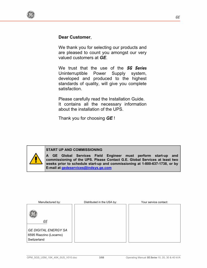
Dear Customer,
We thank you for selecting our products andare pleased to count you amongst our veryvalued customers at GE. We trust that the use of the SG SeriesUninterruptible Power Supply system,developed and produced to the higheststandards of quality, will give you completesatisfaction. Please carefully read the Installation Guide.It contains all the necessary informationabout the installation of the UPS.
Thank you for choosing GE !
START UP AND COMMISSIONING
A GE Global Services Field Engineer must perform start-up and commissioning of the UPS. Please Contact G.E. Global Services at least two weeks prior to schedule start-up and commissioning at 1-800-637-1738, or by E-mail at [email protected]
Manufactured by: Distributed in the USA by: Your service contact:
g GE
GE DIGITAL ENERGY SA 6595 Riazzino (Locarno) Switzerland
g GE
OPM_SGS_USM_10K_40K_0US_V010.doc 4/88 Operating Manual SG Series 10, 20, 30 & 40 kVA
Preface
Congratulations on your choice of a SG Series Uninterruptible Power Supply (UPS). It will help eliminate Load disturbances due to unexpected power problems. This Manual describes the function of the UPS module, the purpose and location of the switches, the meaning of the system events related to the front panel indication, and provides procedures for starting and stopping the equipment.
Please refer to the accompanying Installations Guide, which describes how to prepare the installation site, and it provides weight, dimensions and procedures for moving, installing and connecting the UPS.
While every care has been taken to ensure the completeness and accuracy of this manual, GE assumes no responsibility or liability for any losses or damages resulting from the use of the information contained in this document.
WARNING! SG Series 10, 20, 30 and 40 kVA, is a product that needs to be installed by a licensed and knowledgeable contractor.
We recommend that this manual be kept next to the UPS for future references. If any problems are encountered with the procedures contained in this manual, please contact your Service Center before you proceed.
This document shall not be copied or reproduced without the permission of GE.
Some of the information contained in this manual may be changed without notice to reflect technical improvements.
Safety instructions
Read the safety instructions contained on the following pages carefully before the installation of the UPS, options and Battery System. Pay attention to the rectangular boxes included in the text: They contain important information and warning concerning electrical connections and personnel safety.
Parallel version secured with RPA
When included in the text, this symbol refers to operation needed only for parallel system.
g GE
OPM_SGS_USM_10K_40K_0US_V010.doc 5/88 Operating Manual SG Series 10, 20, 30 & 40 kVA
Table of contents Page 1 IMPORTANT SAFETY INSTRUCTIONS .................................................................7
2 INTRODUCTION.....................................................................................................10
3 DESCRIPTION........................................................................................................11 3.1 BLOCK DIAGRAM AND MAIN ELEMENTS..................................................................11 3.2 OPERATION MODES ...................................................................................................12
3.2.1 Normal operation mode.................................................................................................12 3.2.2 Utility failure operation...................................................................................................12 3.2.3 Utility recovery operation...............................................................................................13 3.2.4 Automatic Bypass..........................................................................................................13 3.2.5 Manual Bypass..............................................................................................................13
3.3 PARALLEL SYSTEM OPERATION ..............................................................................14 3.3.1 Introduction to the parallel system.................................................................................14 3.3.2 Features of RPA parallel system...................................................................................15 3.3.3 System control...............................................................................................................15 3.3.4 Synchronization.............................................................................................................15 3.3.5 Load sharing..................................................................................................................15
3.4 RECTIFIERS PARALLELED ON THE SAME BATTERY..............................................16 3.5 RECYCLING AT THE END OF SERVICE LIFE............................................................17
4 LAYOUT .................................................................................................................18 4.1 LAYOUT SG SERIES 10 AND 20 KVA ..............................................................................18 4.2 LAYOUT SG SERIES 30 AND 40 KVA ..............................................................................19
5 CONTROL PANEL .................................................................................................20 5.1 CONTROL PANEL ........................................................................................................20 5.2 TABLE OF FUNCTIONS AND INDICATIONS ON CONTROL PANEL.........................20
6 LCD SCREEN.........................................................................................................22 6.1 METERING MODE........................................................................................................23 6.2 ALARMS........................................................................................................................26 6.3 PARAMETERS..............................................................................................................27 6.4 EDIT MODE ..................................................................................................................29 6.5 USER PARAMETERS...................................................................................................32 6.6 EVENTS (ALARMS AND MESSAGES) ........................................................................35
6.6.1 Alarms list ......................................................................................................................35 6.6.2 Messages list.................................................................................................................39 6.6.3 Event report SG Series .....................................................................................................41
7 OPERATION...........................................................................................................42 7.1 PROCEDURES FOR SINGLE UPS..............................................................................43
7.1.1 Start-up of the SG Series ..................................................................................................43 7.1.2 Maintenance shutdown (Load on Q2) ...........................................................................44 7.1.3 From Manual Bypass (Q2) to normal function On-line ..................................................45 7.1.4 Complete UPS shutdown (No Load supply) ..................................................................46 7.1.5 Restore to normal operation after “total off”...................................................................47 7.1.6 Restore to normal operation after EPO (Emergency Power Off)...................................48
g GE
OPM_SGS_USM_10K_40K_0US_V010.doc 6/88 Operating Manual SG Series 10, 20, 30 & 40 kVA
7.2 PROCEDURES FOR UPS FUNCTIONING AS FREQUENCY CONVERTER .............49 7.2.1 Start-up of the SG Series as frequency converter ............................................................49 7.2.2 Complete UPS shutdown (No Load supply) ..................................................................50 7.2.3 Restore to normal operation after “total off”...................................................................51 7.2.4 Restore to normal operation after EPO (Emergency Power Off)...................................52
7.3 PROCEDURES FOR PARALLEL SYSTEM..................................................................53 7.3.1 Parallel System start-up ................................................................................................53 7.3.2 Maintenance system shutdown (Load supplied from Q2 on all Units)...........................55 7.3.3 From Manual Bypass (Q2) to normal function On-line ..................................................56 7.3.4 Separate a Unit from the parallel system (System Redundancy)..................................58 7.3.5 Reconnect a Unit to a parallel system...........................................................................59 7.3.6 Parallel system shutdown (No Load supply) .................................................................60 7.3.7 Restore to normal operation after “total off”...................................................................62 7.3.8 Restore to normal operation after EPO (Emergency Power Off)...................................64
7.4 PROCEDURES FOR PARALLEL SYSTEM WITH COMMON BATTERY ....................66 7.4.1 Parallel System start-up ................................................................................................66 7.4.2 Maintenance system shutdown (Load supplied from Q2 on all Units)...........................68 7.4.3 From Manual Bypass (Q2) to normal function On-line ..................................................69 7.4.4 Separate a Unit from the parallel system (System Redundancy)..................................71 7.4.5 Reconnect a Unit to a parallel system...........................................................................72 7.4.6 Parallel system shutdown (No Load supply) .................................................................73 7.4.7 Restore to normal operation after “total off”...................................................................75 7.4.8 Restore to normal operation after EPO (Emergency Power Off)...................................77
8 CUSTOMER INTERFACE......................................................................................79 8.1 CUSTOMER INTERFACE ............................................................................................79
8.1.1 Serial Port J3 .................................................................................................................80 8.1.2 Output free potential contacts .......................................................................................80 8.1.3 Programmable input free contacts ................................................................................81 8.1.4 Gen Set Signaling (GEN ON)........................................................................................81 8.1.5 AUX external Maintenance Bypass...............................................................................81 8.1.6 Auxiliary Power Supply (APS) 24 VDC / 1A ..................................................................81 8.1.7 EPO (Emergency Power Off) Input contact...................................................................82
9 OPTIONS ................................................................................................................83 9.1 BUILT IN UPS OPTIONS ..............................................................................................83 9.2 COMMUNICATION OPTIONS ......................................................................................83 9.3 OPTIONS IN UPS CABINET.........................................................................................83 9.4 CONNECTION FOR OPTIONS.....................................................................................84
9.4.1 Remote Signaling Box (RSB) ........................................................................................84
10 MAINTENANCE......................................................................................................85 10.1 MAINTENANCE ............................................................................................................85
10.1.1 Service check ................................................................................................................85 10.1.2 Fans and ventilation ......................................................................................................85 10.1.3 Other components with limited lifetime..........................................................................85 10.1.4 Battery ...........................................................................................................................85 10.1.5 Long shut-down periods of the UPS-system .................................................................86 10.1.6 UPS room conditions and temperature .........................................................................86 10.1.7 Long shut-down periods of the UPS-system .................................................................86
11 NOTES....................................................................................................................87 11.1 NOTES FORM ..............................................................................................................87
g GE
OPM_SGS_USM_10K_40K_0US_V010.doc 7/88 Operating Manual SG Series 10, 20, 30 & 40 kVA
1 IMPORTANT SAFETY INSTRUCTIONS SAVE THESE INSTRUCTIONS
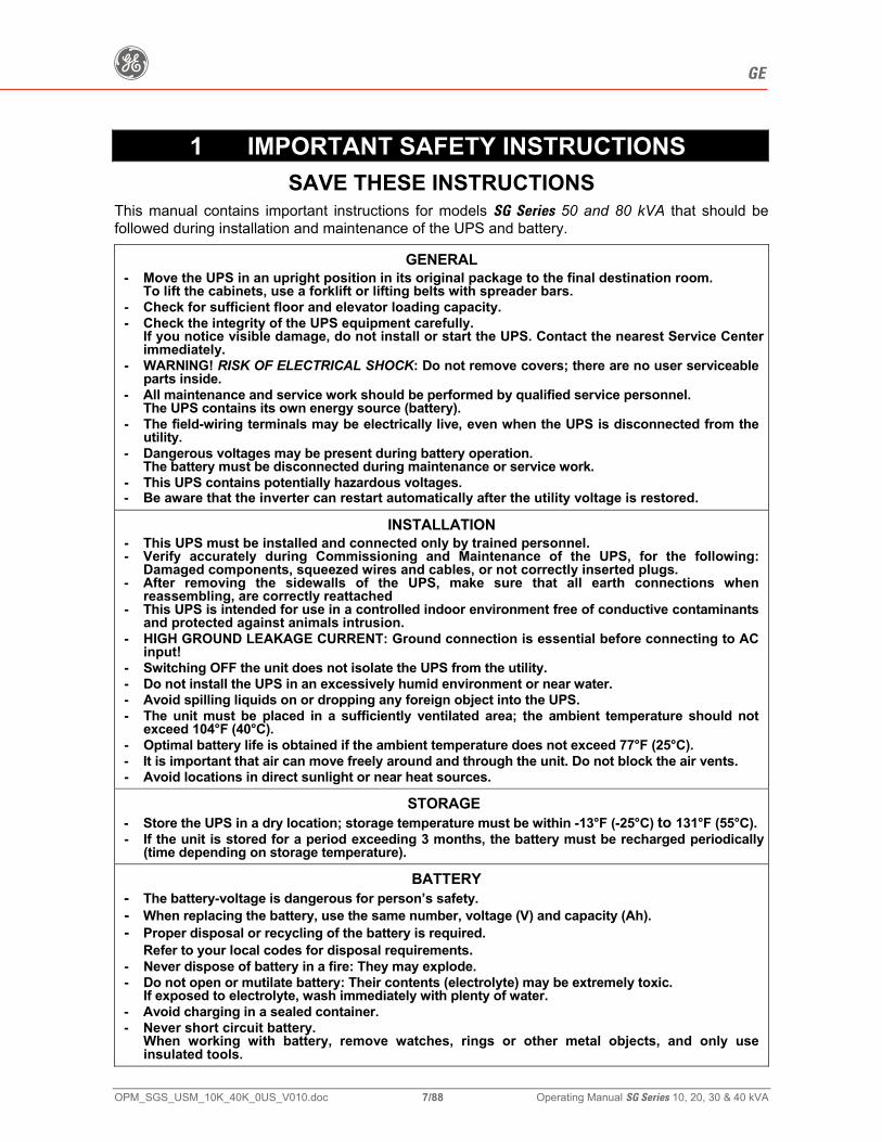
This manual contains important instructions for models SG Series 50 and 80 kVA that should be followed during installation and maintenance of the UPS and battery.
GENERAL
- Move the UPS in an upright position in its original package to the final destination room. To lift the cabinets, use a forklift or lifting belts with spreader bars.
- Check for sufficient floor and elevator loading capacity. - Check the integrity of the UPS equipment carefully.
If you notice visible damage, do not install or start the UPS. Contact the nearest Service Center immediately.
- WARNING! RISK OF ELECTRICAL SHOCK: Do not remove covers; there are no user serviceable parts inside.
- All maintenance and service work should be performed by qualified service personnel. The UPS contains its own energy source (battery).
- The field-wiring terminals may be electrically live, even when the UPS is disconnected from the utility.
- Dangerous voltages may be present during battery operation. The battery must be disconnected during maintenance or service work.
- This UPS contains potentially hazardous voltages. - Be aware that the inverter can restart automatically after the utility voltage is restored.
INSTALLATION
- This UPS must be installed and connected only by trained personnel. - Verify accurately during Commissioning and Maintenance of the UPS, for the following:
Damaged components, squeezed wires and cables, or not correctly inserted plugs. - After removing the sidewalls of the UPS, make sure that all earth connections when
reassembling, are correctly reattached - This UPS is intended for use in a controlled indoor environment free of conductive contaminants
and protected against animals intrusion. - HIGH GROUND LEAKAGE CURRENT: Ground connection is essential before connecting to AC
input! - Switching OFF the unit does not isolate the UPS from the utility. - Do not install the UPS in an excessively humid environment or near water. - Avoid spilling liquids on or dropping any foreign object into the UPS. - The unit must be placed in a sufficiently ventilated area; the ambient temperature should not
exceed 104°F (40°C). - Optimal battery life is obtained if the ambient temperature does not exceed 77°F (25°C). - It is important that air can move freely around and through the unit. Do not block the air vents. - Avoid locations in direct sunlight or near heat sources.
STORAGE
- Store the UPS in a dry location; storage temperature must be within -13°F (-25°C) to 131°F (55°C). - If the unit is stored for a period exceeding 3 months, the battery must be recharged periodically
(time depending on storage temperature).
BATTERY
- The battery-voltage is dangerous for person’s safety. - When replacing the battery, use the same number, voltage (V) and capacity (Ah). - Proper disposal or recycling of the battery is required.
Refer to your local codes for disposal requirements. - Never dispose of battery in a fire: They may explode. - Do not open or mutilate battery: Their contents (electrolyte) may be extremely toxic.
If exposed to electrolyte, wash immediately with plenty of water. - Avoid charging in a sealed container. - Never short circuit battery.
When working with battery, remove watches, rings or other metal objects, and only use insulated tools.
g GE
OPM_SGS_USM_10K_40K_0US_V010.doc 8/88 Operating Manual SG Series 10, 20, 30 & 40 kVA
Safety instructions when working with battery
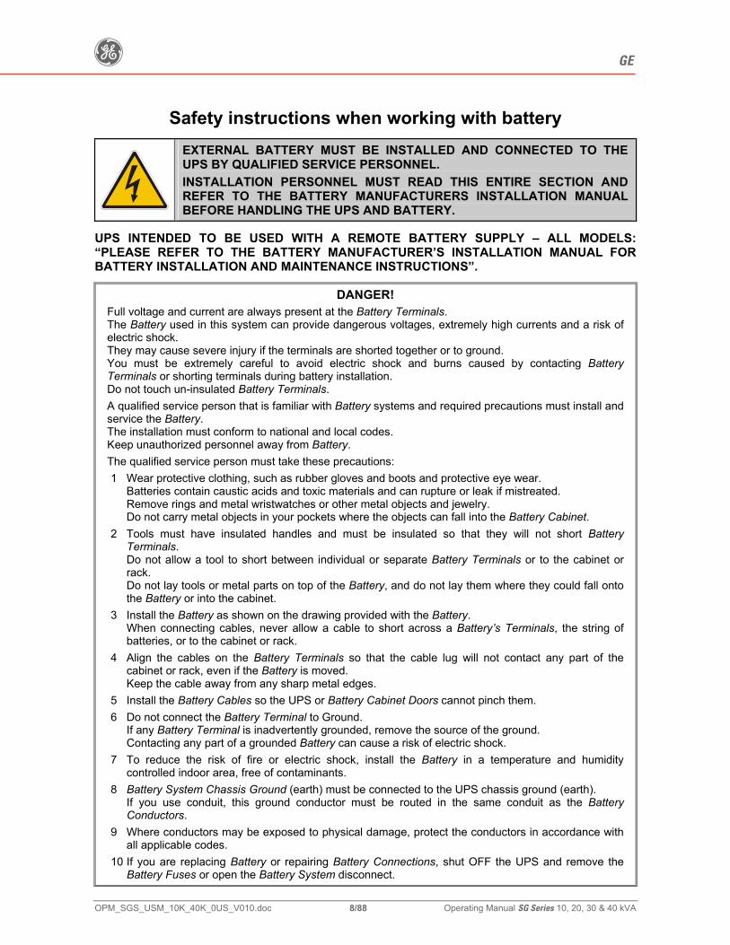
EXTERNAL BATTERY MUST BE INSTALLED AND CONNECTED TO THE UPS BY QUALIFIED SERVICE PERSONNEL. INSTALLATION PERSONNEL MUST READ THIS ENTIRE SECTION AND REFER TO THE BATTERY MANUFACTURERS INSTALLATION MANUAL BEFORE HANDLING THE UPS AND BATTERY.
UPS INTENDED TO BE USED WITH A REMOTE BATTERY SUPPLY – ALL MODELS: “PLEASE REFER TO THE BATTERY MANUFACTURER’S INSTALLATION MANUAL FOR BATTERY INSTALLATION AND MAINTENANCE INSTRUCTIONS”.
DANGER! Full voltage and current are always present at the Battery Terminals. The Battery used in this system can provide dangerous voltages, extremely high currents and a risk of electric shock. They may cause severe injury if the terminals are shorted together or to ground. You must be extremely careful to avoid electric shock and burns caused by contacting Battery Terminals or shorting terminals during battery installation. Do not touch un-insulated Battery Terminals.
A qualified service person that is familiar with Battery systems and required precautions must install and service the Battery. The installation must conform to national and local codes. Keep unauthorized personnel away from Battery.
The qualified service person must take these precautions:
1 Wear protective clothing, such as rubber gloves and boots and protective eye wear. Batteries contain caustic acids and toxic materials and can rupture or leak if mistreated. Remove rings and metal wristwatches or other metal objects and jewelry. Do not carry metal objects in your pockets where the objects can fall into the Battery Cabinet.
2 Tools must have insulated handles and must be insulated so that they will not short Battery Terminals. Do not allow a tool to short between individual or separate Battery Terminals or to the cabinet or rack. Do not lay tools or metal parts on top of the Battery, and do not lay them where they could fall onto the Battery or into the cabinet.
3 Install the Battery as shown on the drawing provided with the Battery. When connecting cables, never allow a cable to short across a Battery’s Terminals, the string of batteries, or to the cabinet or rack.
4 Align the cables on the Battery Terminals so that the cable lug will not contact any part of the cabinet or rack, even if the Battery is moved. Keep the cable away from any sharp metal edges.
5 Install the Battery Cables so the UPS or Battery Cabinet Doors cannot pinch them.
6 Do not connect the Battery Terminal to Ground. If any Battery Terminal is inadvertently grounded, remove the source of the ground. Contacting any part of a grounded Battery can cause a risk of electric shock.
7 To reduce the risk of fire or electric shock, install the Battery in a temperature and humidity controlled indoor area, free of contaminants.
8 Battery System Chassis Ground (earth) must be connected to the UPS chassis ground (earth). If you use conduit, this ground conductor must be routed in the same conduit as the Battery Conductors.
9 Where conductors may be exposed to physical damage, protect the conductors in accordance with all applicable codes.
10 If you are replacing Battery or repairing Battery Connections, shut OFF the UPS and remove the Battery Fuses or open the Battery System disconnect.
g GE
OPM_SGS_USM_10K_40K_0US_V010.doc 9/88 Operating Manual SG Series 10, 20, 30 & 40 kVA
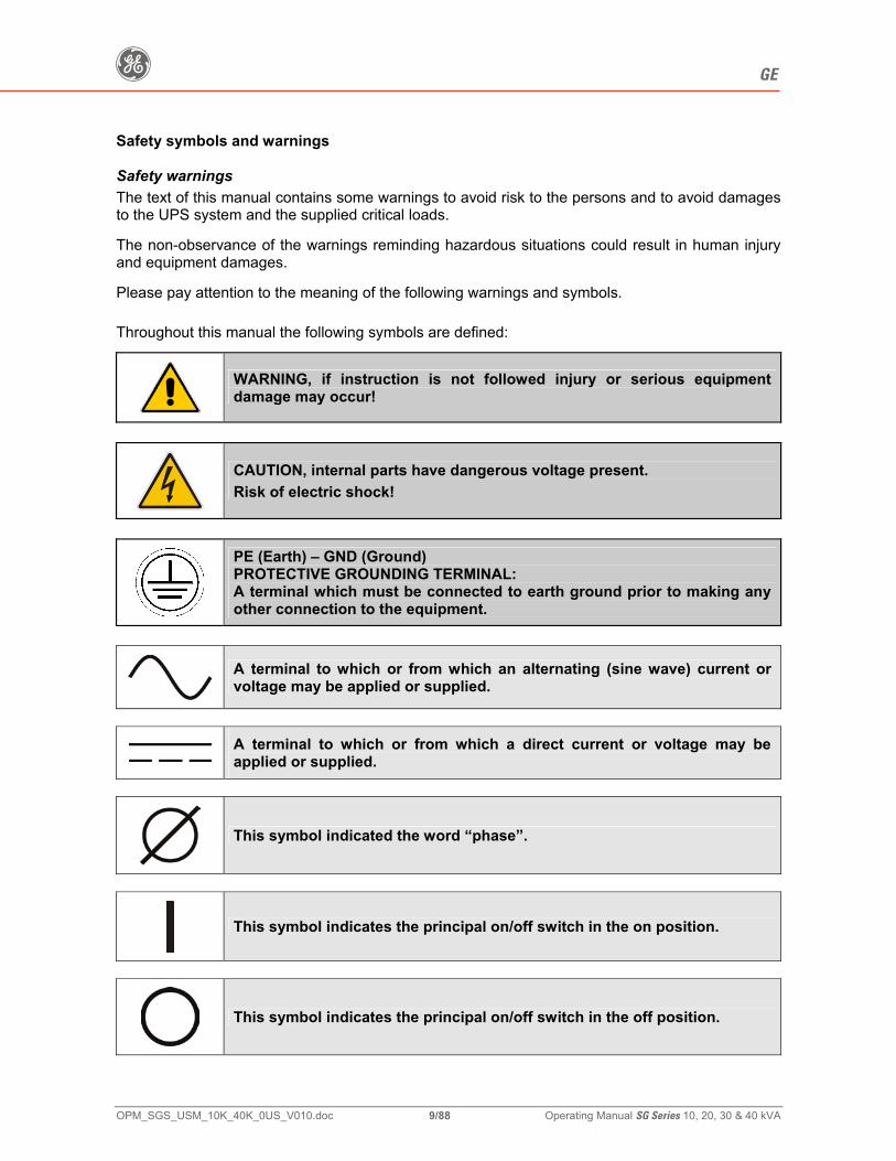
Safety symbols and warnings Safety warnings The text of this manual contains some warnings to avoid risk to the persons and to avoid damages to the UPS system and the supplied critical loads. The non-observance of the warnings reminding hazardous situations could result in human injury and equipment damages. Please pay attention to the meaning of the following warnings and symbols. Throughout this manual the following symbols are defined:
WARNING, if instruction is not followed injury or serious equipment damage may occur!
CAUTION, internal parts have dangerous voltage present. Risk of electric shock!
PE (Earth) – GND (Ground) PROTECTIVE GROUNDING TERMINAL: A terminal which must be connected to earth ground prior to making any other connection to the equipment.
A terminal to which or from which an alternating (sine wave) current or voltage may be applied or supplied.
A terminal to which or from which a direct current or voltage may be applied or supplied.
This symbol indicated the word “phase”.
This symbol indicates the principal on/off switch in the on position.
This symbol indicates the principal on/off switch in the off position.
g GE
OPM_SGS_USM_10K_40K_0US_V010.doc 10/88 Operating Manual SG Series 10, 20, 30 & 40 kVA
2 INTRODUCTION An Uninterruptible Power Supply (UPS) provides the power for critical loads that need a reliable, continuous, disturbance free supply. In case the power provided by the Utility Fails, or exceeds the permitted tolerances, the power to supply the Load is provided by the Battery for the specified time at the rated Load (or longer at a reduced Load) or until the Utility power returns. SG Series is a true double conversion On-line UPS system where the Load is continuously supplied by the Inverter through the Rectifier. In case of trouble on the Inverter Output Voltage, or when overload or short-circuit on the output occur, the Load is instantly transferred to the Utility via the Automatic Bypass. The UPS automatically returns to normal mode when the failure condition is restored. Key features: • More Critical equipment supported
Rated at 0.8 Power Factor, SG Series delivers more real power than other UPS in the market. With today’s trend toward power factor corrected loads, SG Series can support more total Load than any other UPS available, allowing you to support a greater number of today’s enterprise computing Power Factor Corrected (PFC) equipment.
• No single point of failure
Redundant Parallel Architecture (RPA) is an exclusive GE technology. With RPA, SG Series UPS are controlled in a true peer-to-peer configuration where all critical elements and functions (including Bypass) are redundant. SG Series is designed to be the most reliable power protection system available on the market today.
• High Efficiency
Using IGBT technology and Space Vector Modulation (SVM) strategy, SG Series offers low output voltage distortion and provides efficiencies up to 93%.
• Fully digital
Digital Signal Processor (DSP), Flash memory and SVM strategy, are the technology corner stones of new age of power quality and power reliability.
• Extremely flexible
Tailor made power protection to meet your individual installation requirements; SG Series offers various options like input harmonic filters and our comprehensive JUMP software suite for mission control and data protection to cover all your application needs.
g GE
OPM_SGS_USM_10K_40K_0US_V010.doc 11/88 Operating Manual SG Series 10, 20, 30 & 40 kVA
3 DESCRIPTION
3.1 BLOCK DIAGRAM AND MAIN ELEMENTS
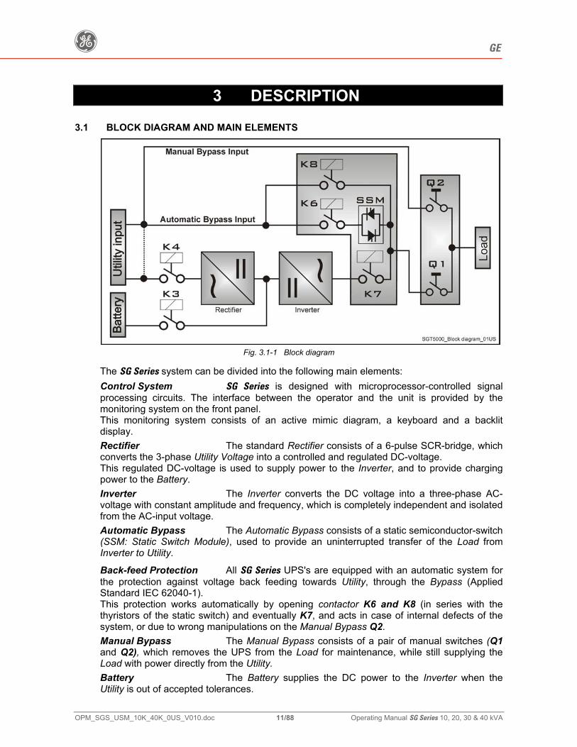
Fig. 3.1-1 Block diagram The SG Series system can be divided into the following main elements:
Control System SG Series is designed with microprocessor-controlled signal processing circuits. The interface between the operator and the unit is provided by the monitoring system on the front panel. This monitoring system consists of an active mimic diagram, a keyboard and a backlit display.
Rectifier The standard Rectifier consists of a 6-pulse SCR-bridge, which converts the 3-phase Utility Voltage into a controlled and regulated DC-voltage. This regulated DC-voltage is used to supply power to the Inverter, and to provide charging power to the Battery.
Inverter The Inverter converts the DC voltage into a three-phase AC-voltage with constant amplitude and frequency, which is completely independent and isolated from the AC-input voltage.
Automatic Bypass The Automatic Bypass consists of a static semiconductor-switch (SSM: Static Switch Module), used to provide an uninterrupted transfer of the Load from Inverter to Utility.
Back-feed Protection All SG Series UPS's are equipped with an automatic system for the protection against voltage back feeding towards Utility, through the Bypass (Applied Standard IEC 62040-1). This protection works automatically by opening contactor K6 and K8 (in series with the thyristors of the static switch) and eventually K7, and acts in case of internal defects of the system, or due to wrong manipulations on the Manual Bypass Q2.
Manual Bypass The Manual Bypass consists of a pair of manual switches (Q1 and Q2), which removes the UPS from the Load for maintenance, while still supplying the Load with power directly from the Utility.
Battery The Battery supplies the DC power to the Inverter when the Utility is out of accepted tolerances.
g GE
OPM_SGS_USM_10K_40K_0US_V010.doc 12/88 Operating Manual SG Series 10, 20, 30 & 40 kVA
3.2 OPERATION MODES
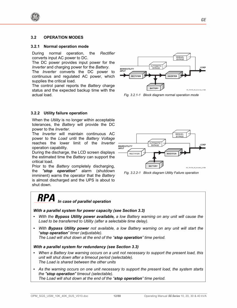
3.2.1 Normal operation mode During normal operation, the Rectifier converts input AC power to DC. The DC power provides input power for the Inverter and charging power for the Battery. The Inverter converts the DC power to continuous and regulated AC power, which supplies the critical load. The control panel reports the Battery charge status and the expected backup time with the actual load. Fig. 3.2.1-1 Block diagram normal operation mode
3.2.2 Utility failure operation When the Utility is no longer within acceptable tolerances, the Battery will provide the DC power to the Inverter. The Inverter will maintain continuous AC power to the Load until the Battery Voltage reaches the lower limit of the Inverter operation capability. During the discharge, the LCD screen displays the estimated time the Battery can support the critical load. Prior to the Battery completely discharging, the "stop operation" alarm (shutdown imminent) warns the operator that the Battery is almost discharged and the UPS is about to shut down.
Fig. 3.2.2-1 Block diagram Utility Failure operation
In case of parallel operation With a parallel system for power capacity (see Section 3.3) • With the Bypass Utility power available, a low Battery warning on any unit will cause the
Load to be transferred to Utility (after a selectable time delay).
• With Bypass Utility power not available, a low Battery warning on any unit will start the “stop operation” timer (adjustable). The Load will shut down at the end of the “stop operation” time period.
With a parallel system for redundancy (see Section 3.3) • When a Battery low warning occurs on a unit not necessary to support the present load, this
unit will shut down after a timeout period (selectable). The Load is shared between the other units
• As the warning occurs on one unit necessary to support the present load, the system starts the "stop operation" timeout (selectable). The Load will shut down at the end of the “stop operation” time period.
g GE
OPM_SGS_USM_10K_40K_0US_V010.doc 13/88 Operating Manual SG Series 10, 20, 30 & 40 kVA
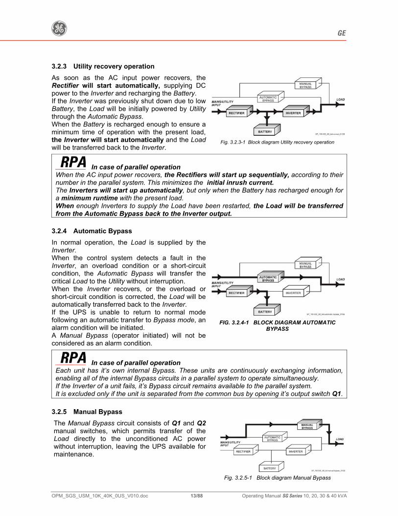
3.2.3 Utility recovery operation As soon as the AC input power recovers, the Rectifier will start automatically, supplying DC power to the Inverter and recharging the Battery. If the Inverter was previously shut down due to low Battery, the Load will be initially powered by Utility through the Automatic Bypass. When the Battery is recharged enough to ensure a minimum time of operation with the present load, the Inverter will start automatically and the Load will be transferred back to the Inverter.
Fig. 3.2.3-1 Block diagram Utility recovery operation
In case of parallel operation When the AC input power recovers, the Rectifiers will start up sequentially, according to their number in the parallel system. This minimizes the initial inrush current. The Inverters will start up automatically, but only when the Battery has recharged enough for a minimum runtime with the present load. When enough Inverters to supply the Load have been restarted, the Load will be transferred from the Automatic Bypass back to the Inverter output.
3.2.4 Automatic Bypass In normal operation, the Load is supplied by the Inverter. When the control system detects a fault in the Inverter, an overload condition or a short-circuit condition, the Automatic Bypass will transfer the critical Load to the Utility without interruption. When the Inverter recovers, or the overload or short-circuit condition is corrected, the Load will be automatically transferred back to the Inverter. If the UPS is unable to return to normal mode following an automatic transfer to Bypass mode, an alarm condition will be initiated. A Manual Bypass (operator initiated) will not be considered as an alarm condition.
FIG. 3.2.4-1 BLOCK DIAGRAM AUTOMATIC BYPASS
In case of parallel operation Each unit has it’s own internal Bypass. These units are continuously exchanging information, enabling all of the internal Bypass circuits in a parallel system to operate simultaneously. If the Inverter of a unit fails, it’s Bypass circuit remains available to the parallel system. It is excluded only if the unit is separated from the common bus by opening it’s output switch Q1.
3.2.5 Manual Bypass The Manual Bypass circuit consists of Q1 and Q2 manual switches, which permits transfer of the Load directly to the unconditioned AC power without interruption, leaving the UPS available for maintenance.
Fig. 3.2.5-1 Block diagram Manual Bypass
g GE
OPM_SGS_USM_10K_40K_0US_V010.doc 14/88 Operating Manual SG Series 10, 20, 30 & 40 kVA
3.3 PARALLEL SYSTEM OPERATION
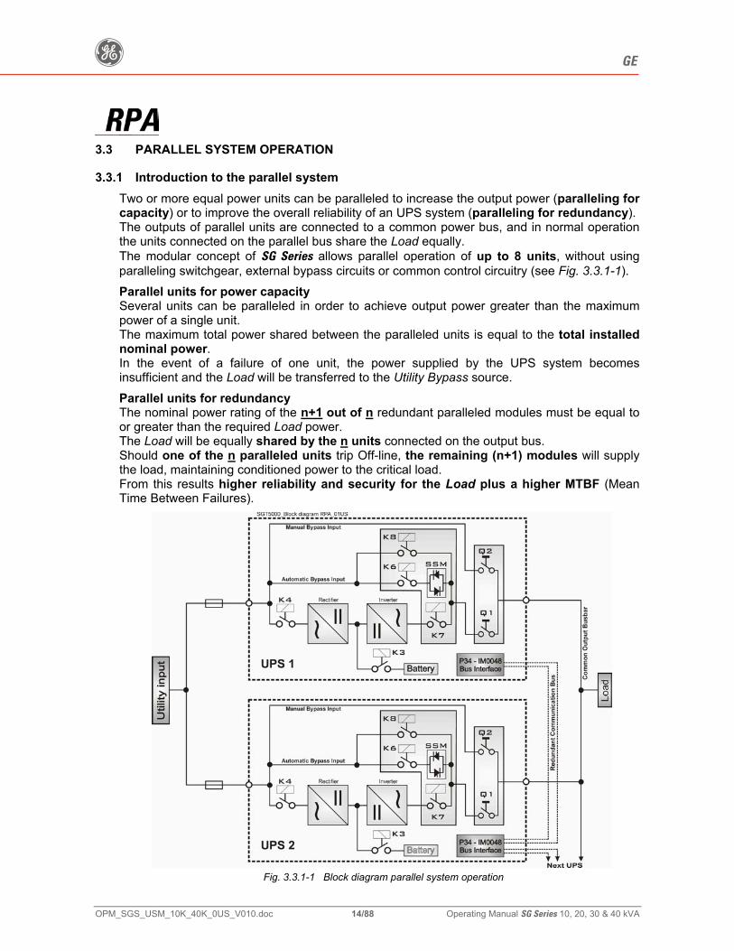
3.3.1 Introduction to the parallel system Two or more equal power units can be paralleled to increase the output power (paralleling for capacity) or to improve the overall reliability of an UPS system (paralleling for redundancy). The outputs of parallel units are connected to a common power bus, and in normal operation the units connected on the parallel bus share the Load equally. The modular concept of SG Series allows parallel operation of up to 8 units, without using paralleling switchgear, external bypass circuits or common control circuitry (see Fig. 3.3.1-1).
Parallel units for power capacity Several units can be paralleled in order to achieve output power greater than the maximum power of a single unit. The maximum total power shared between the paralleled units is equal to the total installed nominal power. In the event of a failure of one unit, the power supplied by the UPS system becomes insufficient and the Load will be transferred to the Utility Bypass source.
Parallel units for redundancy The nominal power rating of the n+1 out of n redundant paralleled modules must be equal to or greater than the required Load power. The Load will be equally shared by the n units connected on the output bus. Should one of the n paralleled units trip Off-line, the remaining (n+1) modules will supply the load, maintaining conditioned power to the critical load. From this results higher reliability and security for the Load plus a higher MTBF (Mean Time Between Failures).
Fig. 3.3.1-1 Block diagram parallel system operation
g GE
OPM_SGS_USM_10K_40K_0US_V010.doc 15/88 Operating Manual SG Series 10, 20, 30 & 40 kVA
3.3.2 Features of RPA parallel system The SG Series parallel system is designed to provide a complete Redundant Parallel Architecture, and is free from common equipment. Not only the Inverters are redundant, but also the Bypass functions are designed with redundant modular concept. When one UPS needs maintenance or service, the Load is powered by the other units supplying the Load bus. The redundant communication bus to which all units are connected keeps each unit informed about the status of all the other units. The control panel located on each unit allows controlling and monitoring the status of this unit.
3.3.3 System control A high-speed redundant, serial communication bus guarantees the exchange of data and thus the communication between the CPU's of each unit. Each module controls it's own function and operational status and communicates with all other modules, in order to act or react if necessary, adapting it to the new conditions.
3.3.4 Synchronization All units are identical, but one unit is arbitrarily selected as the reference and all the other units synchronize to this unit, which in turn, synchronizes to the Utility Bypass voltage, as long as the later is within tolerances. In case of reference failure, another unit in the parallel system is automatically chosen to take over the reference role. The Bypass Input for all the units of the parallel system must be supplied from the same AC source (no phase shift allowed between them).
3.3.5 Load sharing On each unit of the parallel system, Inverter Output Voltage and Current are measured and applied to a Load sharing bus. An eventual difference between the units is therefore automatically equalized.
It is strongly recommended that no transformers, automatic circuit breakers or fuses should be inserted between the unit’s output and the Load common bus bars. However, it is recommended that a disconnect or isolation switch be inserted.
g GE
OPM_SGS_USM_10K_40K_0US_V010.doc 16/88 Operating Manual SG Series 10, 20, 30 & 40 kVA
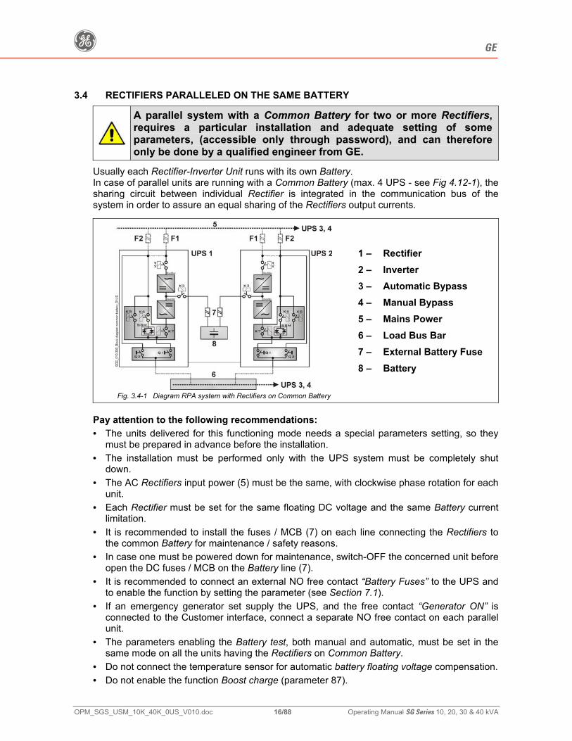
3.4 RECTIFIERS PARALLELED ON THE SAME BATTERY
A parallel system with a Common Battery for two or more Rectifiers, requires a particular installation and adequate setting of some parameters, (accessible only through password), and can therefore only be done by a qualified engineer from GE.
Usually each Rectifier-Inverter Unit runs with its own Battery. In case of parallel units are running with a Common Battery (max. 4 UPS - see Fig 4.12-1), the sharing circuit between individual Rectifier is integrated in the communication bus of the system in order to assure an equal sharing of the Rectifiers output currents.
Fig. 3.4-1 Diagram RPA system with Rectifiers on Common Battery
1 – 2 – 3 – 4 – 5 – 6 – 7 – 8 –
Rectifier Inverter Automatic Bypass Manual Bypass Mains Power Load Bus Bar External Battery Fuse Battery
Pay attention to the following recommendations: • The units delivered for this functioning mode needs a special parameters setting, so they
must be prepared in advance before the installation. • The installation must be performed only with the UPS system must be completely shut
down. • The AC Rectifiers input power (5) must be the same, with clockwise phase rotation for each
unit. • Each Rectifier must be set for the same floating DC voltage and the same Battery current
limitation. • It is recommended to install the fuses / MCB (7) on each line connecting the Rectifiers to
the common Battery for maintenance / safety reasons. • In case one must be powered down for maintenance, switch-OFF the concerned unit before
open the DC fuses / MCB on the Battery line (7). • It is recommended to connect an external NO free contact “Battery Fuses” to the UPS and
to enable the function by setting the parameter (see Section 7.1). • If an emergency generator set supply the UPS, and the free contact “Generator ON” is
connected to the Customer interface, connect a separate NO free contact on each parallel unit.
• The parameters enabling the Battery test, both manual and automatic, must be set in the same mode on all the units having the Rectifiers on Common Battery.
• Do not connect the temperature sensor for automatic battery floating voltage compensation. • Do not enable the function Boost charge (parameter 87).
g GE
OPM_SGS_USM_10K_40K_0US_V010.doc 17/88 Operating Manual SG Series 10, 20, 30 & 40 kVA
3.5 RECYCLING AT THE END OF SERVICE LIFE
NOTE! This product has been designed to respect the environment, using materials and components respecting eco-design rules. It does not contain CFCs (Carbon Fluor Clorid) or HCFCs (Halogen Carbon Fluor Clorid).
Packing material recycling GE, in compliance with environment protection, uses only environmentally friendly material. UPS packing materials must be recycled in compliance with all applicable regulations.
WARNING! Leads contained in the batteries is a dangerous substance for the environment, therefore it must be correctly recycled by specialized companies!
g GE
OPM_SGS_USM_10K_40K_0US_V010.doc 18/88 Operating Manual SG Series 10, 20, 30 & 40 kVA
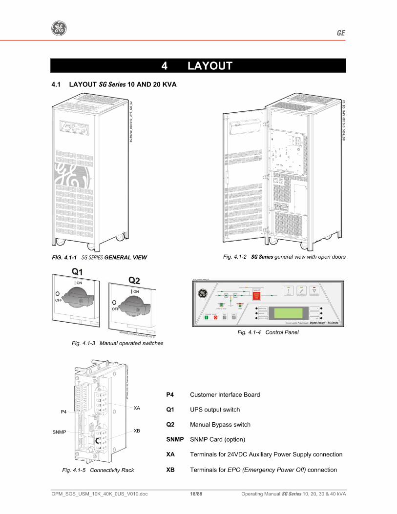
4 LAYOUT 4.1 LAYOUT SG Series 10 AND 20 KVA
SGT5
000_
030-
040_
UPS
_GE_
02
FIG. 4.1-1 SG SERIES GENERAL VIEW
SGT5
000_
010-
020_
UPS
_GE_
03
Fig. 4.1-2 SG Series general view with open doors
Fig. 4.1-3 Manual operated switches
Fig. 4.1-4 Control Panel
P4 Customer Interface Board
Q1 UPS output switch
Q2 Manual Bypass switch
SNMP SNMP Card (option)
XA Terminals for 24VDC Auxiliary Power Supply connection
SGT5
000_
100-
150_
Cus
tom
er in
terfa
ce_0
3
SNMP 1234
1234 XA
P4
XB
Fig. 4.1-5 Connectivity Rack XB Terminals for EPO (Emergency Power Off) connection
g GE
OPM_SGS_USM_10K_40K_0US_V010.doc 19/88 Operating Manual SG Series 10, 20, 30 & 40 kVA
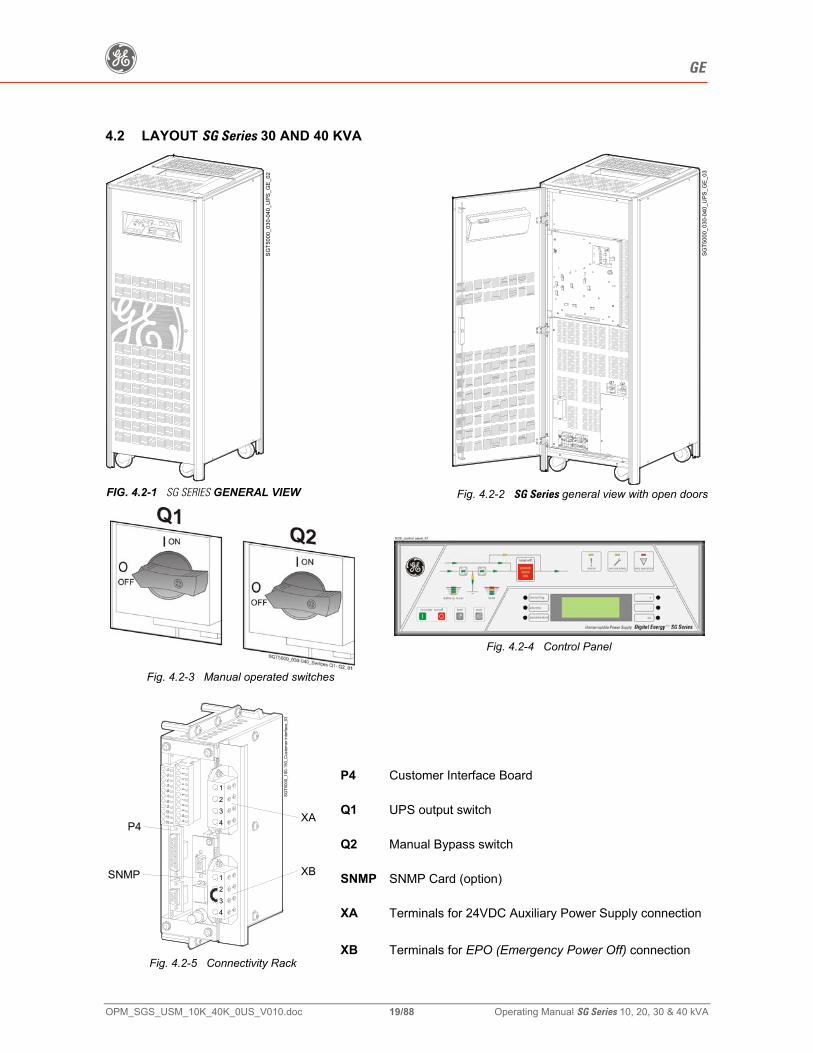
4.2 LAYOUT SG Series 30 AND 40 KVA
SGT5
000_
030-
040_
UPS
_GE_
02
FIG. 4.2-1 SG SERIES GENERAL VIEW
SGT5
000_
030-
040_
UPS
_GE_
03
Q1 Q2ON
OFF
OFF
ON
Fig. 4.2-2 SG Series general view with open doors
Fig. 4.2-3 Manual operated switches
Fig. 4.2-4 Control Panel
P4 Customer Interface Board
Q1 UPS output switch
Q2 Manual Bypass switch
SNMP SNMP Card (option)
XA Terminals for 24VDC Auxiliary Power Supply connection
SGT5
000_
100-
150_
Cus
tom
er in
terfa
ce_0
3
SNMP 1234
1234 XA
P4
XB
Fig. 4.2-5 Connectivity Rack
XB Terminals for EPO (Emergency Power Off) connection
g GE
OPM_SGS_USM_10K_40K_0US_V010.doc 20/88 Operating Manual SG Series 10, 20, 30 & 40 kVA
5 CONTROL PANEL
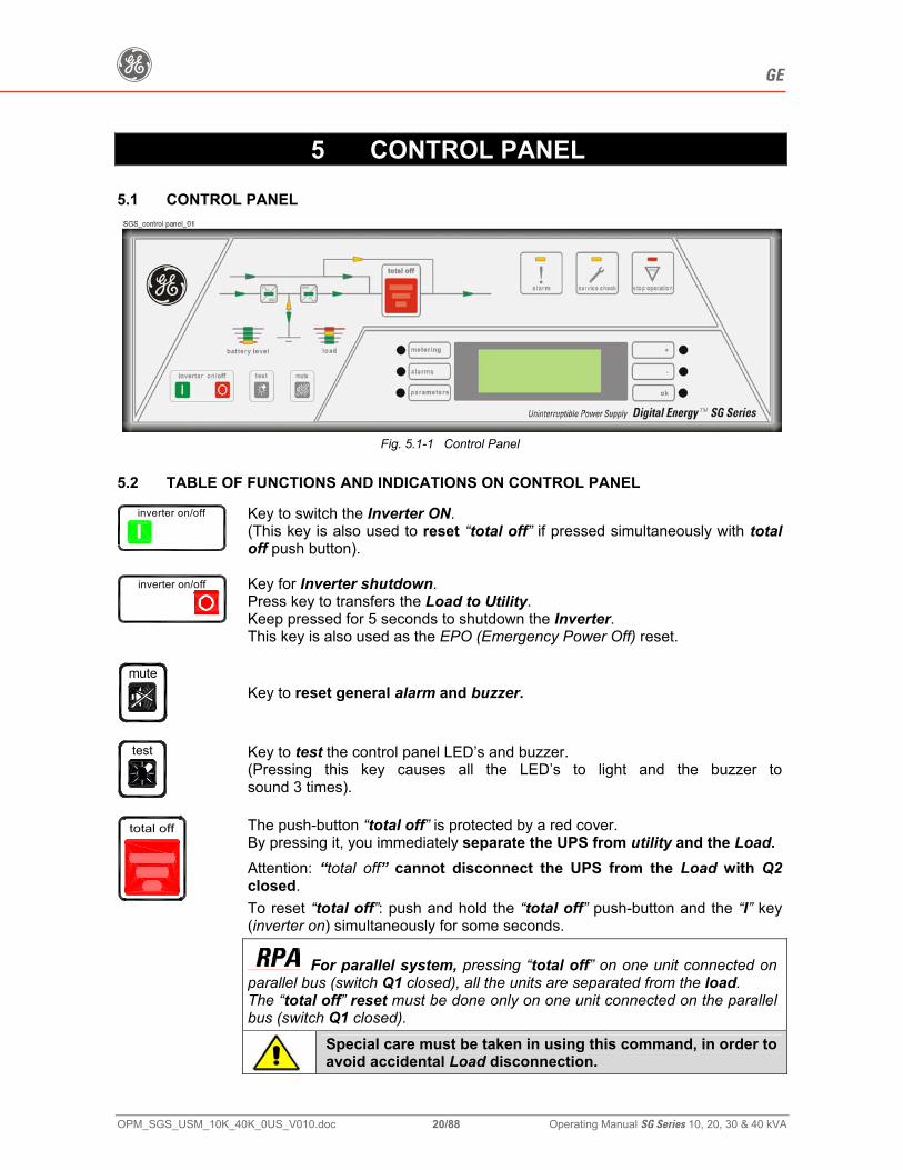
5.1 CONTROL PANEL
Fig. 5.1-1 Control Panel
5.2 TABLE OF FUNCTIONS AND INDICATIONS ON CONTROL PANEL
inverter on/off
Key to switch the Inverter ON. (This key is also used to reset “total off” if pressed simultaneously with total off push button).
inverter on/off
Key for Inverter shutdown. Press key to transfers the Load to Utility. Keep pressed for 5 seconds to shutdown the Inverter. This key is also used as the EPO (Emergency Power Off) reset.
mute
Key to reset general alarm and buzzer.
test
Key to test the control panel LED’s and buzzer. (Pressing this key causes all the LED’s to light and the buzzer tosound 3 times).
The push-button “total off” is protected by a red cover. By pressing it, you immediately separate the UPS from utility and the Load.
Attention: “total off” cannot disconnect the UPS from the Load with Q2 closed.
To reset “total off”: push and hold the “total off” push-button and the “I” key (inverter on) simultaneously for some seconds.
For parallel system, pressing “total off” on one unit connected on parallel bus (switch Q1 closed), all the units are separated from the load. The “total off” reset must be done only on one unit connected on the parallel bus (switch Q1 closed).
Special care must be taken in using this command, in order to avoid accidental Load disconnection.
g GE
OPM_SGS_USM_10K_40K_0US_V010.doc 21/88 Operating Manual SG Series 10, 20, 30 & 40 kVA
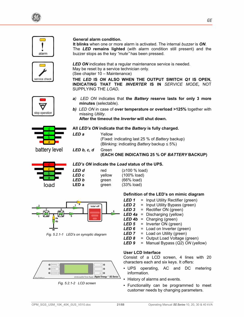
alarm
General alarm condition. It blinks when one or more alarm is activated. The internal buzzer is ON. The LED remains lighted (with alarm condition still present) and the buzzer stops as the key “mute” has been pressed.
service check
LED ON indicates that a regular maintenance service is needed. May be reset by a service technician only. (See chapter 10 – Maintenance) THE LED IS ON ALSO WHEN THE OUTPUT SWITCH Q1 IS OPEN, INDICATING THAT THE INVERTER IS IN SERVICE MODE, NOT SUPPLYING THE LOAD.
a) LED ON indicates that the Battery reserve lasts for only 3 more minutes (selectable).
b) LED ON in case of over temperature or overload >125% together with missing Utility. After the timeout the Inverter will shut down.
All LED’s ON indicate that the Battery is fully charged. LED a Yellow
(Fixed: indicating last 25 % of Battery backup) (Blinking: indicating Battery backup ≤ 5%)
LED b, c, d Green (EACH ONE INDICATING 25 % OF BATTERY BACKUP)
LED’s ON indicate the Load status of the UPS. LED d red (≥100 % load) LED c yellow (100% load) LED b green (66% load) LED a green (33% load)
Fig. 5.2.1-1 LED’s on synoptic diagram
Definition of the LED’s on mimic diagram LED 1 = Input Utility Rectifier (green) LED 2 = Input Utility Bypass (green) LED 3 = Rectifier ON (green) LED 4a = Discharging (yellow) LED 4b = Charging (green) LED 5 = Inverter ON (green) LED 6 = Load on Inverter (green) LED 7 = Load on Utility (green) LED 8 = Output Load Voltage (green) LED 9 = Manual Bypass (Q2) ON (yellow)
Fig. 5.2.1-2 LCD screen
User LCD Interface Consist of a LCD screen, 4 lines with 20 characters each and six keys. It offers: • UPS operating, AC and DC metering
information. • History of alarms and events. • Functionality can be programmed to meet
customer needs by changing parameters.
g GE
OPM_SGS_USM_10K_40K_0US_V010.doc 22/88 Operating Manual SG Series 10, 20, 30 & 40 kVA
6 LCD SCREEN
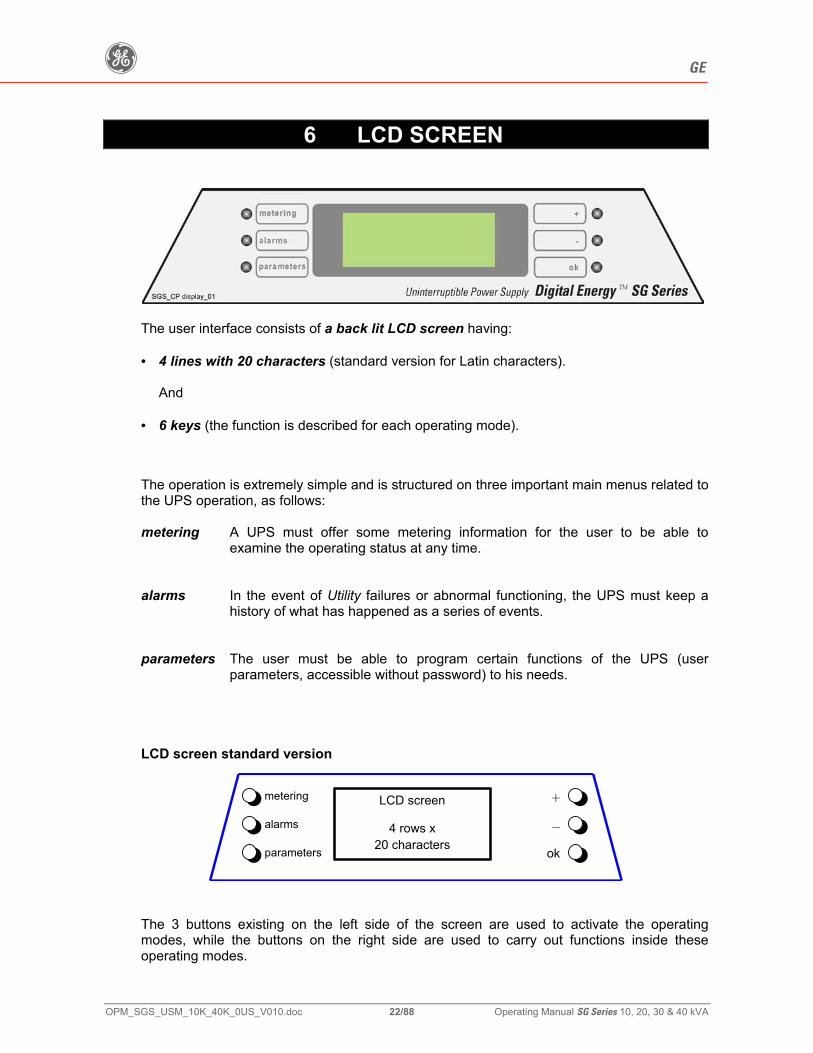
The user interface consists of a back lit LCD screen having: • 4 lines with 20 characters (standard version for Latin characters).
And • 6 keys (the function is described for each operating mode). The operation is extremely simple and is structured on three important main menus related to the UPS operation, as follows: metering A UPS must offer some metering information for the user to be able to
examine the operating status at any time. alarms In the event of Utility failures or abnormal functioning, the UPS must keep a
history of what has happened as a series of events. parameters The user must be able to program certain functions of the UPS (user
parameters, accessible without password) to his needs. LCD screen standard version
LCD screen
4 rows x
20 characters
metering
alarms
parameters
+
–
ok
The 3 buttons existing on the left side of the screen are used to activate the operating modes, while the buttons on the right side are used to carry out functions inside these operating modes.
g GE
OPM_SGS_USM_10K_40K_0US_V010.doc 23/88 Operating Manual SG Series 10, 20, 30 & 40 kVA
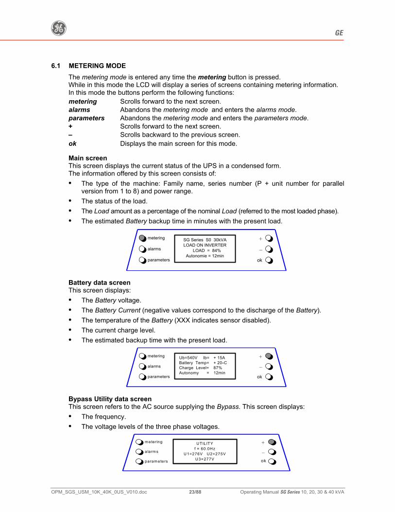
6.1 METERING MODE The metering mode is entered any time the metering button is pressed. While in this mode the LCD will display a series of screens containing metering information. In this mode the buttons perform the following functions: metering Scrolls forward to the next screen. alarms Abandons the metering mode and enters the alarms mode. parameters Abandons the metering mode and enters the parameters mode. + Scrolls forward to the next screen. – Scrolls backward to the previous screen. ok Displays the main screen for this mode. Main screen This screen displays the current status of the UPS in a condensed form. The information offered by this screen consists of: • The type of the machine: Family name, series number (P + unit number for parallel
version from 1 to 8) and power range. • The status of the load. • The Load amount as a percentage of the nominal Load (referred to the most loaded phase). • The estimated Battery backup time in minutes with the present load.
SG Series S0 30kVA LOAD ON INVERTER
LOAD = 84% Autonomie = 12min
metering
alarms
parameters
+
–
ok
Battery data screen This screen displays: • The Battery voltage. • The Battery Current (negative values correspond to the discharge of the Battery). • The temperature of the Battery (XXX indicates sensor disabled). • The current charge level. • The estimated backup time with the present load.
Ub=540V Ib= + 15A
Battery Temp= + 20°C Charge Level= 87% Autonomy = 12min
metering
alarms
parameters
+
–
ok
Bypass Utility data screen This screen refers to the AC source supplying the Bypass. This screen displays: • The frequency. • The voltage levels of the three phase voltages.
UTILITY
f = 60.0Hz U1=276V U2=275V
U3=277V
m etering
alarm s
param eters
+
–ok
g GE
OPM_SGS_USM_10K_40K_0US_V010.doc 24/88 Operating Manual SG Series 10, 20, 30 & 40 kVA
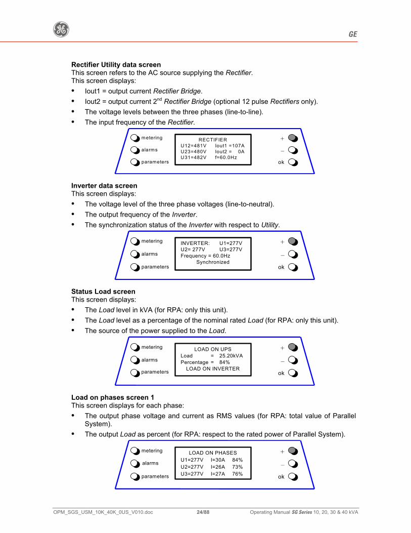
Rectifier Utility data screen This screen refers to the AC source supplying the Rectifier. This screen displays: • Iout1 = output current Rectifier Bridge. • Iout2 = output current 2nd Rectifier Bridge (optional 12 pulse Rectifiers only). • The voltage levels between the three phases (line-to-line). • The input frequency of the Rectifier.
RECTIFIER
U12=481V Iout1 =107A U23=480V Iout2 = 0A U31=482V f=60.0Hz
metering
alarms
parameters
+
–
ok
Inverter data screen This screen displays: • The voltage level of the three phase voltages (line-to-neutral). • The output frequency of the Inverter. • The synchronization status of the Inverter with respect to Utility.
INVERTER: U1=277V U2= 277V U3=277V Frequency = 60.0Hz
Synchronized
metering
alarms
parameters
+
–
ok
Status Load screen This screen displays: • The Load level in kVA (for RPA: only this unit). • The Load level as a percentage of the nominal rated Load (for RPA: only this unit). • The source of the power supplied to the Load.
LOAD ON UPS
Load = 25.20kVA Percentage = 84%
LOAD ON INVERTER
metering
alarms
parameters
+
–
ok
Load on phases screen 1 This screen displays for each phase: • The output phase voltage and current as RMS values (for RPA: total value of Parallel
System). • The output Load as percent (for RPA: respect to the rated power of Parallel System).
LOAD ON PHASES
U1=277V I=30A 84% U2=277V I=26A 73% U3=277V I=27A 76%
metering
alarms
parameters
+
–
ok
g GE
OPM_SGS_USM_10K_40K_0US_V010.doc 25/88 Operating Manual SG Series 10, 20, 30 & 40 kVA
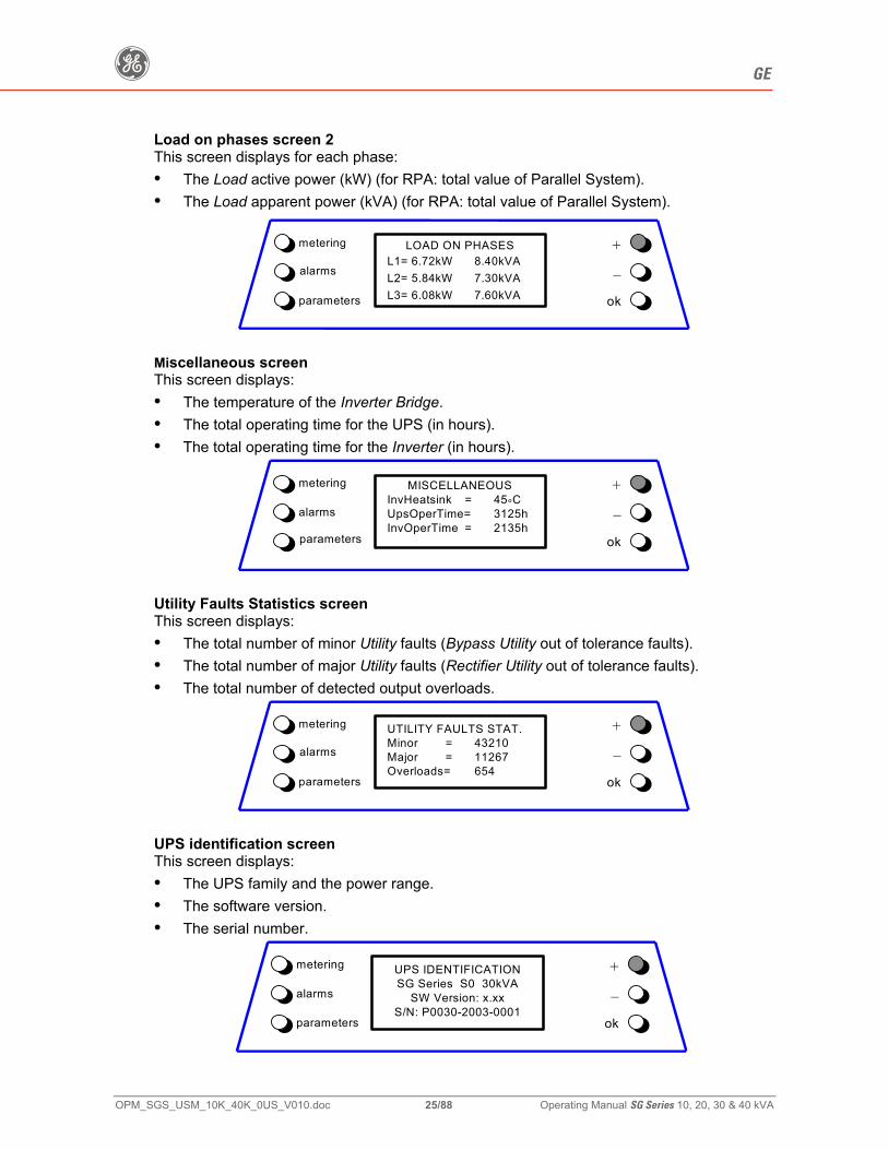
Load on phases screen 2 This screen displays for each phase: • The Load active power (kW) (for RPA: total value of Parallel System). • The Load apparent power (kVA) (for RPA: total value of Parallel System).
LOAD ON PHASES
L1= 6.72kW 8.40kVA L2= 5.84kW 7.30kVA L3= 6.08kW 7.60kVA
metering
alarms
parameters
+
–
ok
Miscellaneous screen This screen displays: • The temperature of the Inverter Bridge. • The total operating time for the UPS (in hours). • The total operating time for the Inverter (in hours).
MISCELLANEOUS
InvHeatsink = 45°C UpsOperTime= 3125h InvOperTime = 2135h
metering
alarms
parameters
+
–
ok
Utility Faults Statistics screen This screen displays: • The total number of minor Utility faults (Bypass Utility out of tolerance faults). • The total number of major Utility faults (Rectifier Utility out of tolerance faults). • The total number of detected output overloads.
UTILITY FAULTS STAT. Minor = 43210 Major = 11267 Overloads= 654
metering
alarms
parameters
+
–
ok
UPS identification screen This screen displays: • The UPS family and the power range. • The software version. • The serial number.
UPS IDENTIFICATION SG Series S0 30kVA
SW Version: x.xx S/N: P0030-2003-0001
metering
alarms
parameters
+
–
ok
g GE
OPM_SGS_USM_10K_40K_0US_V010.doc 26/88 Operating Manual SG Series 10, 20, 30 & 40 kVA
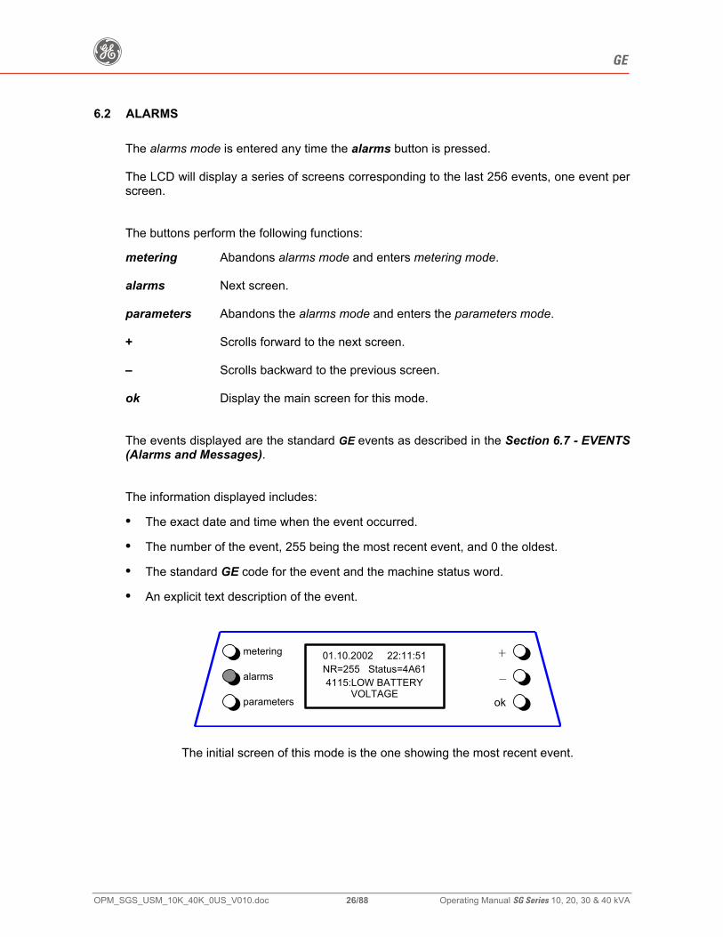
6.2 ALARMS The alarms mode is entered any time the alarms button is pressed. The LCD will display a series of screens corresponding to the last 256 events, one event per screen. The buttons perform the following functions: metering Abandons alarms mode and enters metering mode. alarms Next screen. parameters Abandons the alarms mode and enters the parameters mode. + Scrolls forward to the next screen. – Scrolls backward to the previous screen. ok Display the main screen for this mode. The events displayed are the standard GE events as described in the Section 6.7 - EVENTS (Alarms and Messages). The information displayed includes:
• The exact date and time when the event occurred.
• The number of the event, 255 being the most recent event, and 0 the oldest.
• The standard GE code for the event and the machine status word.
• An explicit text description of the event.
01.10.2002 22:11:51 NR=255 Status=4A61 4115:LOW BATTERY
VOLTAGE
metering
alarms
parameters
+
–
ok
The initial screen of this mode is the one showing the most recent event.
g GE
OPM_SGS_USM_10K_40K_0US_V010.doc 27/88 Operating Manual SG Series 10, 20, 30 & 40 kVA
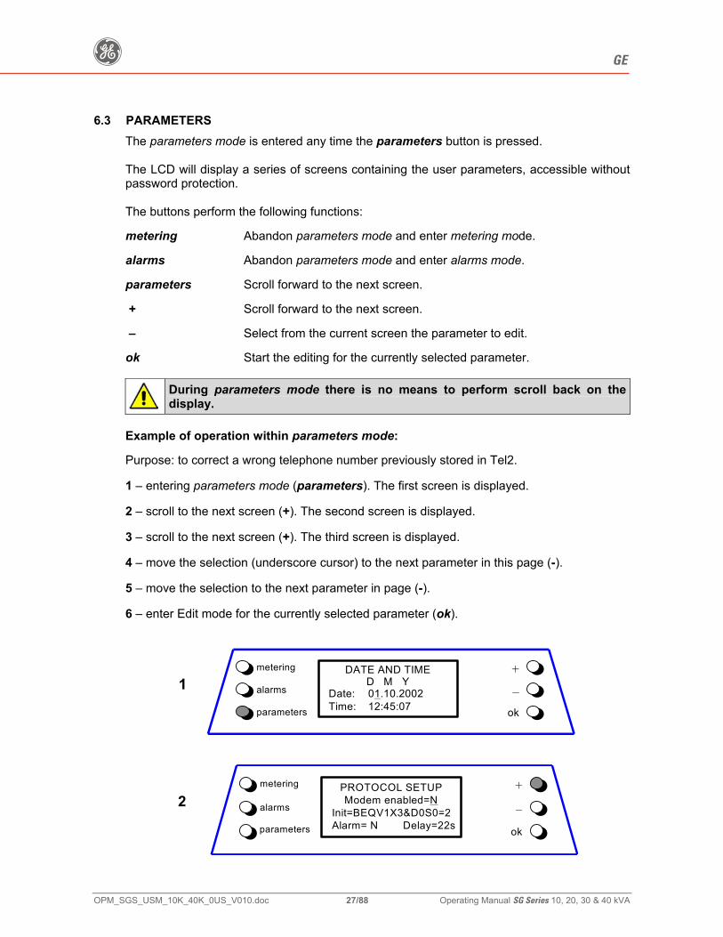
6.3 PARAMETERS The parameters mode is entered any time the parameters button is pressed. The LCD will display a series of screens containing the user parameters, accessible without password protection. The buttons perform the following functions: metering Abandon parameters mode and enter metering mode. alarms Abandon parameters mode and enter alarms mode. parameters Scroll forward to the next screen. + Scroll forward to the next screen. – Select from the current screen the parameter to edit. ok Start the editing for the currently selected parameter.
During parameters mode there is no means to perform scroll back on the display.
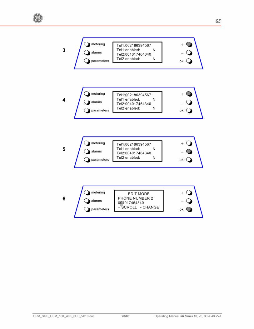
Example of operation within parameters mode: Purpose: to correct a wrong telephone number previously stored in Tel2. 1 – entering parameters mode (parameters). The first screen is displayed. 2 – scroll to the next screen (+). The second screen is displayed. 3 – scroll to the next screen (+). The third screen is displayed. 4 – move the selection (underscore cursor) to the next parameter in this page (-). 5 – move the selection to the next parameter in page (-). 6 – enter Edit mode for the currently selected parameter (ok).
DATE AND TIME
D M Y Date: 01.10.2002 Time: 12:45:07
metering
1 alarms
parameters
+
–ok
PROTOCOL SETUP Modem enabled=N
Init=BEQV1X3&D0S0=2 Alarm= N Delay=22s
metering
2 alarms
parameters
+
–
ok
g GE
OPM_SGS_USM_10K_40K_0US_V010.doc 28/88 Operating Manual SG Series 10, 20, 30 & 40 kVA
Tel1:002186394567 Tel1 enabled: N Tel2:004017464340 Tel2 enabled: N
metering
3 alarms
parameters
+
–
ok
Tel1:002186394567 Tel1 enabled: N Tel2:004017464340 Tel2 enabled: N
metering
4 alarms
parameters
+
–
ok
Tel1:002186394567 Tel1 enabled: N Tel2:004017464340 Tel2 enabled: N
metering
5 alarms
parameters
+
–
ok
EDIT MODE PHONE NUMBER 2 004017464340 + SCROLL - CHANGE
metering
6 alarms
parameters
+
–
ok
g GE
OPM_SGS_USM_10K_40K_0US_V010.doc 29/88 Operating Manual SG Series 10, 20, 30 & 40 kVA
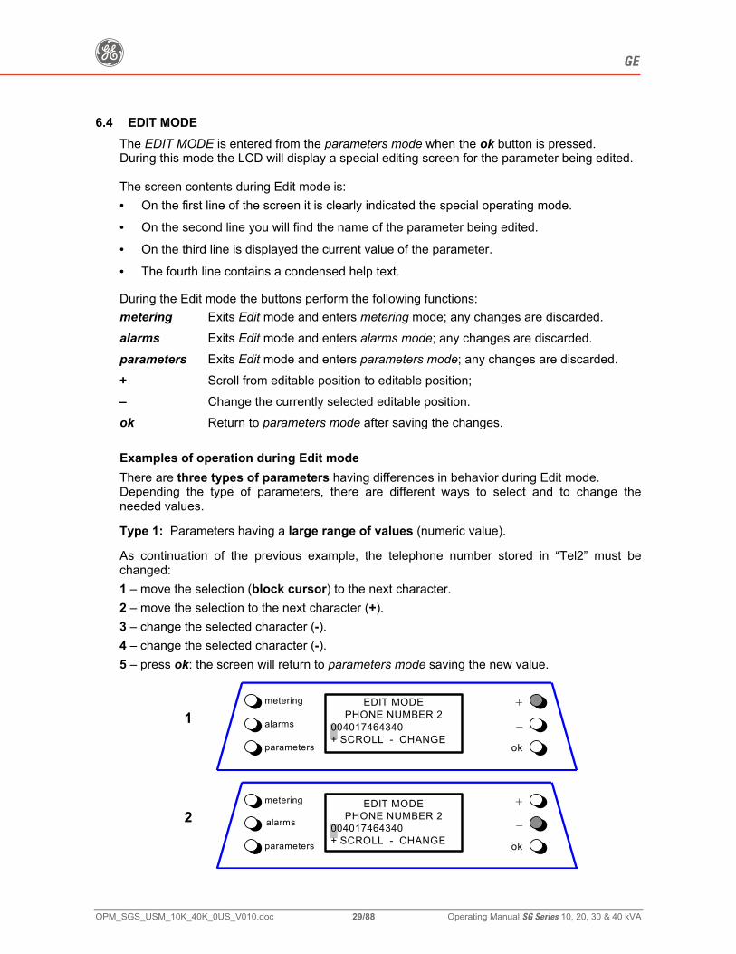
6.4 EDIT MODE The EDIT MODE is entered from the parameters mode when the ok button is pressed. During this mode the LCD will display a special editing screen for the parameter being edited. The screen contents during Edit mode is: • On the first line of the screen it is clearly indicated the special operating mode.
• On the second line you will find the name of the parameter being edited.
• On the third line is displayed the current value of the parameter.
• The fourth line contains a condensed help text. During the Edit mode the buttons perform the following functions:
metering Exits Edit mode and enters metering mode; any changes are discarded. alarms Exits Edit mode and enters alarms mode; any changes are discarded. parameters Exits Edit mode and enters parameters mode; any changes are discarded. + Scroll from editable position to editable position; – Change the currently selected editable position. ok Return to parameters mode after saving the changes. Examples of operation during Edit mode
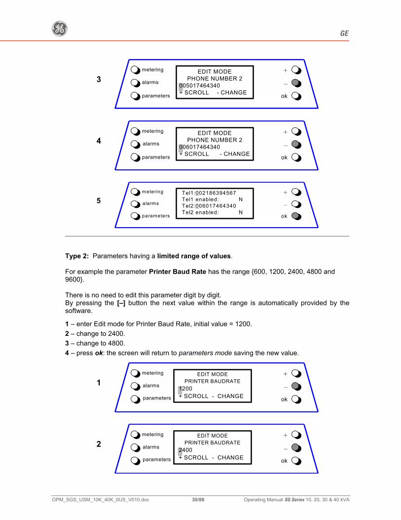
There are three types of parameters having differences in behavior during Edit mode. Depending the type of parameters, there are different ways to select and to change the needed values. Type 1: Parameters having a large range of values (numeric value). As continuation of the previous example, the telephone number stored in “Tel2” must be changed: 1 – move the selection (block cursor) to the next character. 2 – move the selection to the next character (+). 3 – change the selected character (-). 4 – change the selected character (-). 5 – press ok: the screen will return to parameters mode saving the new value.
EDIT MODE PHONE NUMBER 2
004017464340 + SCROLL - CHANGE
metering
1 alarms
parameters
+
–
ok
EDIT MODE
PHONE NUMBER 2 004017464340 + SCROLL - CHANGE
metering
2 alarms
parameters
+
–
ok
g GE
OPM_SGS_USM_10K_40K_0US_V010.doc 30/88 Operating Manual SG Series 10, 20, 30 & 40 kVA
EDIT MODE
PHONE NUMBER 2 005017464340 + SCROLL - CHANGE
metering
3 alarms
parameters
+
–
ok
EDIT MODE
PHONE NUMBER 2 006017464340 + SCROLL - CHANGE
metering
4 alarms
parameters
+
–
ok
Tel1:002186394567 Tel1 enabled: N Tel2:006017464340 Tel2 enabled: N
metering
5 alarms
parameters
+
–
ok
Type 2: Parameters having a limited range of values. For example the parameter Printer Baud Rate has the range {600, 1200, 2400, 4800 and 9600}. There is no need to edit this parameter digit by digit. By pressing the [–] button the next value within the range is automatically provided by the software.
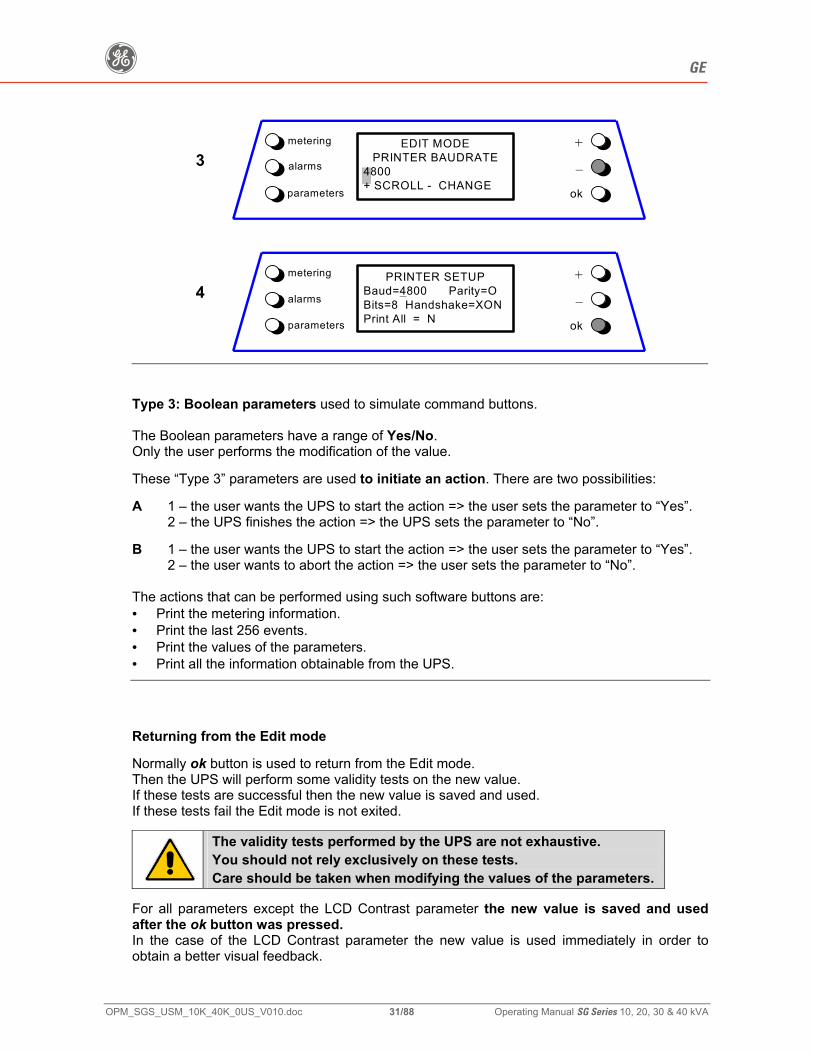
1 – enter Edit mode for Printer Baud Rate, initial value = 1200. 2 – change to 2400. 3 – change to 4800. 4 – press ok: the screen will return to parameters mode saving the new value.
EDIT MODE
PRINTER BAUDRATE 1200 + SCROLL - CHANGE
metering
1 alarms
parameters
+
–
ok
EDIT MODE
PRINTER BAUDRATE 2400 + SCROLL - CHANGE
metering
2 alarms
parameters
+
–
ok
g GE
OPM_SGS_USM_10K_40K_0US_V010.doc 31/88 Operating Manual SG Series 10, 20, 30 & 40 kVA
metering
3 alarms
parameters
+
–
ok
EDIT MODE PRINTER BAUDRATE
4800 + SCROLL - CHANGE
PRINTER SETUP
Baud=4800 Parity=O Bits=8 Handshake=XON Print All = N
metering
4 alarms
parameters
+
–
ok
Type 3: Boolean parameters used to simulate command buttons. The Boolean parameters have a range of Yes/No. Only the user performs the modification of the value. These “Type 3” parameters are used to initiate an action. There are two possibilities: A 1 – the user wants the UPS to start the action => the user sets the parameter to “Yes”. 2 – the UPS finishes the action => the UPS sets the parameter to “No”. B 1 – the user wants the UPS to start the action => the user sets the parameter to “Yes”. 2 – the user wants to abort the action => the user sets the parameter to “No”. The actions that can be performed using such software buttons are: • Print the metering information. • Print the last 256 events. • Print the values of the parameters. • Print all the information obtainable from the UPS.
Returning from the Edit mode Normally ok button is used to return from the Edit mode. Then the UPS will perform some validity tests on the new value. If these tests are successful then the new value is saved and used. If these tests fail the Edit mode is not exited.
The validity tests performed by the UPS are not exhaustive. You should not rely exclusively on these tests. Care should be taken when modifying the values of the parameters.
For all parameters except the LCD Contrast parameter the new value is saved and used after the ok button was pressed. In the case of the LCD Contrast parameter the new value is used immediately in order to obtain a better visual feedback.
g GE
OPM_SGS_USM_10K_40K_0US_V010.doc 32/88 Operating Manual SG Series 10, 20, 30 & 40 kVA
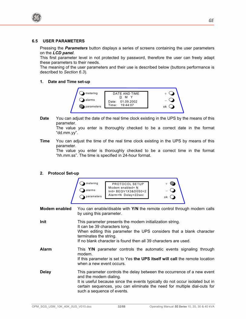
6.5 USER PARAMETERS Pressing the Parameters button displays a series of screens containing the user parameters on the LCD panel. This first parameter level in not protected by password, therefore the user can freely adapt these parameters to their needs. The meaning of the user parameters and their use is described below (buttons performance is described to Section 6.3). 1. Date and Time set-up
DATE AND TIME D M Y
Date: 01.09.2002 Time: 19:44:07
metering
alarms
parameters
+
–ok
Date You can adjust the date of the real time clock existing in the UPS by the means of this
parameter. The value you enter is thoroughly checked to be a correct date in the format “dd.mm.yy”.
Time You can adjust the time of the real time clock existing in the UPS by means of this
parameter. The value you enter is thoroughly checked to be a correct time in the format “hh.mm.ss”. The time is specified in 24-hour format.
2. Protocol Set-up
PROTOCOL SETUP Modem enabled= N Init= BEQV1X3&D0S0=2Alarm=N Delay=22sec
metering
alarms
parameters
+
–
ok
Modem enabled You can enable/disable with Y/N the remote control through modem calls
by using this parameter. Init This parameter presents the modem initialization string. It can be 39 characters long. When editing this parameter the UPS considers that a blank character
terminates the string. If no blank character is found then all 39 characters are used. Alarm This Y/N parameter controls the automatic events signaling through
modem. If this parameter is set to Yes the UPS itself will call the remote location
when a new event occurs. Delay This parameter controls the delay between the occurrence of a new event
and the modem dialing. It is useful because since the events typically do not occur isolated but in
certain sequences, you can eliminate the need for multiple dial-outs for such a sequence of events.
g GE
OPM_SGS_USM_10K_40K_0US_V010.doc 33/88 Operating Manual SG Series 10, 20, 30 & 40 kVA
3. Telephone numbers
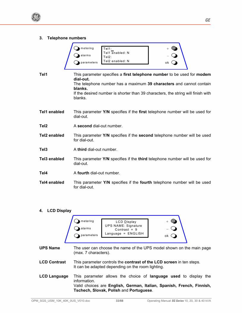
Tel1: Tel1 enabled: N Tel2: Tel2 enabled: N
m etering
a larm s
param eters
+
–
ok
Tel1 This parameter specifies a first telephone number to be used for modem
dial-out. The telephone number has a maximum 39 characters and cannot contain blanks. If the desired number is shorter than 39 characters, the string will finish with blanks.
Tel1 enabled This parameter Y/N specifies if the first telephone number will be used for
dial-out. Tel2 A second dial-out number. Tel2 enabled This parameter Y/N specifies if the second telephone number will be used
for dial-out. Tel3 A third dial-out number. Tel3 enabled This parameter Y/N specifies if the third telephone number will be used for
dial-out. Tel4 A fourth dial-out number. Tel4 enabled This parameter Y/N specifies if the fourth telephone number will be used
for dial-out. 4. LCD Display
LCD Display UPS NAME: Signature
Contrast = 9 Language = ENGLISH
metering
alarms
parameters
+
–
ok
UPS Name The user can choose the name of the UPS model shown on the main page
(max. 7 characters). LCD Contrast This parameter controls the contrast of the LCD screen in ten steps.
It can be adapted depending on the room lighting. LCD Language This parameter allows the choice of language used to display the
information. Valid choices are English, German, Italian, Spanish, French, Finnish, Tschech, Slovak, Polish and Portuguese.
g GE
OPM_SGS_USM_10K_40K_0US_V010.doc 34/88 Operating Manual SG Series 10, 20, 30 & 40 kVA
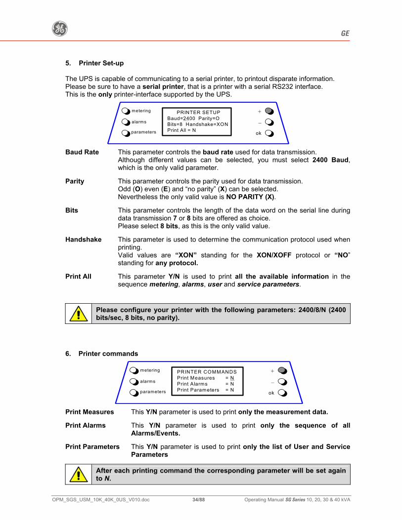
5. Printer Set-up The UPS is capable of communicating to a serial printer, to printout disparate information. Please be sure to have a serial printer, that is a printer with a serial RS232 interface. This is the only printer-interface supported by the UPS.
PRINTER SETUP Baud=2400 Parity=O Bits=8 Handshake=XONPrint All = N
metering
alarms
parameters
+
–
ok
Baud Rate This parameter controls the baud rate used for data transmission.
Although different values can be selected, you must select 2400 Baud, which is the only valid parameter.
Parity This parameter controls the parity used for data transmission. Odd (O) even (E) and “no parity” (X) can be selected. Nevertheless the only valid value is NO PARITY (X). Bits This parameter controls the length of the data word on the serial line during
data transmission 7 or 8 bits are offered as choice. Please select 8 bits, as this is the only valid value. Handshake This parameter is used to determine the communication protocol used when
printing. Valid values are “XON” standing for the XON/XOFF protocol or “NO”
standing for any protocol. Print All This parameter Y/N is used to print all the available information in the
sequence metering, alarms, user and service parameters.
Please configure your printer with the following parameters: 2400/8/N (2400 bits/sec, 8 bits, no parity).
6. Printer commands
PRINTER COMMANDS Print Measures = N Print Alarms = N Print Parameters = N
metering
alarms
parameters
+
–
ok
Print Measures This Y/N parameter is used to print only the measurement data. Print Alarms This Y/N parameter is used to print only the sequence of all
Alarms/Events. Print Parameters This Y/N parameter is used to print only the list of User and Service
Parameters
After each printing command the corresponding parameter will be set again to N.
g GE
OPM_SGS_USM_10K_40K_0US_V010.doc 35/88 Operating Manual SG Series 10, 20, 30 & 40 kVA
6.6 EVENTS (ALARMS AND MESSAGES)
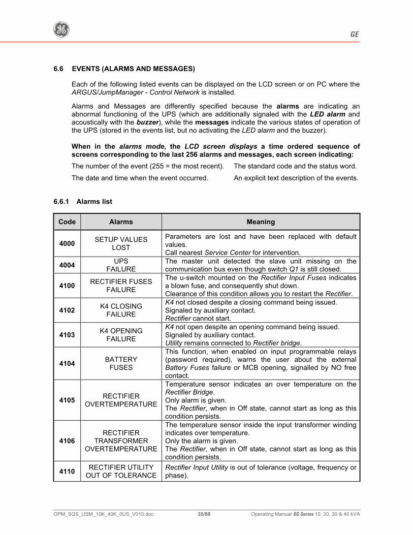
Each of the following listed events can be displayed on the LCD screen or on PC where the ARGUS/JumpManager - Control Network is installed. Alarms and Messages are differently specified because the alarms are indicating an abnormal functioning of the UPS (which are additionally signaled with the LED alarm and acoustically with the buzzer), while the messages indicate the various states of operation of the UPS (stored in the events list, but no activating the LED alarm and the buzzer). When in the alarms mode, the LCD screen displays a time ordered sequence of screens corresponding to the last 256 alarms and messages, each screen indicating:
The number of the event (255 = the most recent). The date and time when the event occurred.
The standard code and the status word.An explicit text description of the events.
6.6.1 Alarms list
Code Alarms Meaning
4000 SETUP VALUES LOST
Parameters are lost and have been replaced with default values. Call nearest Service Center for intervention.
4004 UPS FAILURE
The master unit detected the slave unit missing on the communication bus even though switch Q1 is still closed.
4100 RECTIFIER FUSES FAILURE
The u-switch mounted on the Rectifier Input Fuses indicates a blown fuse, and consequently shut down. Clearance of this condition allows you to restart the Rectifier.
4102 K4 CLOSING FAILURE
K4 not closed despite a closing command being issued. Signaled by auxiliary contact. Rectifier cannot start.
4103 K4 OPENING FAILURE
K4 not open despite an opening command being issued. Signaled by auxiliary contact. Utility remains connected to Rectifier bridge.
4104 BATTERY FUSES
This function, when enabled on input programmable relays (password required), warns the user about the external Battery Fuses failure or MCB opening, signalled by NO free contact.
4105 RECTIFIER OVERTEMPERATURE
Temperature sensor indicates an over temperature on the Rectifier Bridge. Only alarm is given. The Rectifier, when in Off state, cannot start as long as this condition persists.
4106 RECTIFIER
TRANSFORMER OVERTEMPERATURE
The temperature sensor inside the input transformer winding indicates over temperature. Only the alarm is given. The Rectifier, when in Off state, cannot start as long as this condition persists.
4110 RECTIFIER UTILITY OUT OF TOLERANCE
Rectifier Input Utility is out of tolerance (voltage, frequency or phase).
g GE
OPM_SGS_USM_10K_40K_0US_V010.doc 36/88 Operating Manual SG Series 10, 20, 30 & 40 kVA
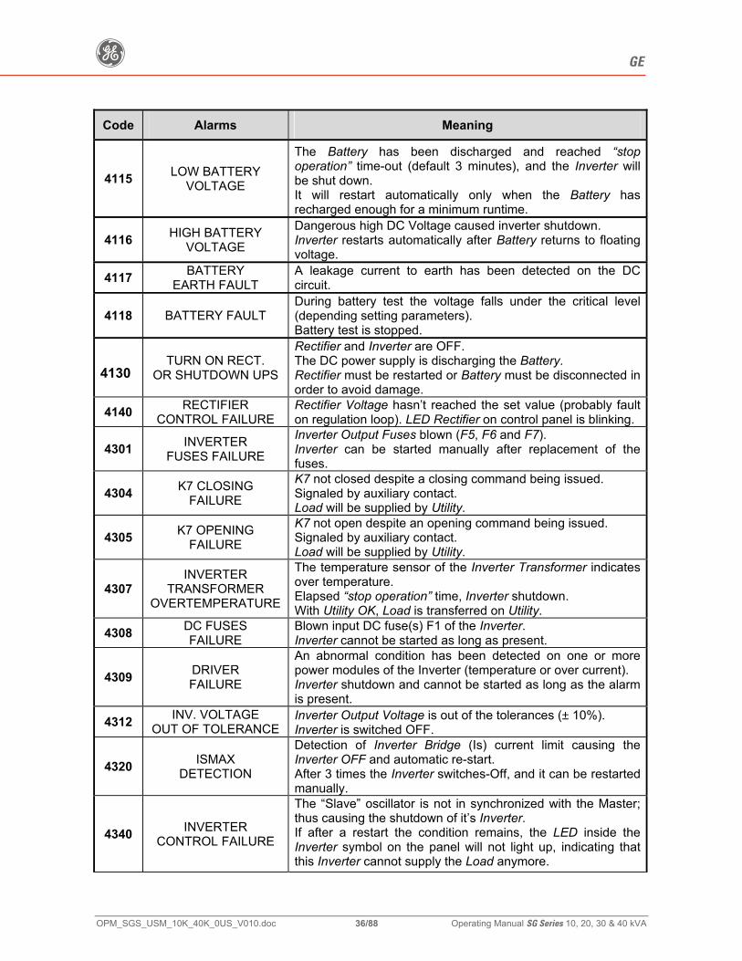
Code Alarms Meaning
4115 LOW BATTERY VOLTAGE
The Battery has been discharged and reached “stop operation” time-out (default 3 minutes), and the Inverter will be shut down. It will restart automatically only when the Battery has recharged enough for a minimum runtime.
4116 HIGH BATTERY VOLTAGE
Dangerous high DC Voltage caused inverter shutdown. Inverter restarts automatically after Battery returns to floating voltage.
4117 BATTERY EARTH FAULT
A leakage current to earth has been detected on the DC circuit.
4118 BATTERY FAULT During battery test the voltage falls under the critical level (depending setting parameters). Battery test is stopped.
4130 TURN ON RECT.
OR SHUTDOWN UPS
Rectifier and Inverter are OFF. The DC power supply is discharging the Battery. Rectifier must be restarted or Battery must be disconnected in order to avoid damage.
4140 RECTIFIER CONTROL FAILURE
Rectifier Voltage hasn’t reached the set value (probably fault on regulation loop). LED Rectifier on control panel is blinking.
4301 INVERTER FUSES FAILURE
Inverter Output Fuses blown (F5, F6 and F7). Inverter can be started manually after replacement of the fuses.
4304 K7 CLOSING FAILURE
K7 not closed despite a closing command being issued. Signaled by auxiliary contact. Load will be supplied by Utility.
4305 K7 OPENING FAILURE
K7 not open despite an opening command being issued. Signaled by auxiliary contact. Load will be supplied by Utility.
4307 INVERTER
TRANSFORMER OVERTEMPERATURE
The temperature sensor of the Inverter Transformer indicates over temperature. Elapsed “stop operation” time, Inverter shutdown. With Utility OK, Load is transferred on Utility.
4308 DC FUSES FAILURE
Blown input DC fuse(s) F1 of the Inverter. Inverter cannot be started as long as present.
4309 DRIVER FAILURE
An abnormal condition has been detected on one or more power modules of the Inverter (temperature or over current). Inverter shutdown and cannot be started as long as the alarm is present.
4312 INV. VOLTAGE OUT OF TOLERANCE
Inverter Output Voltage is out of the tolerances (± 10%). Inverter is switched OFF.
4320 ISMAX DETECTION
Detection of Inverter Bridge (Is) current limit causing the Inverter OFF and automatic re-start. After 3 times the Inverter switches-Off, and it can be restarted manually.
4340 INVERTER CONTROL FAILURE
The “Slave” oscillator is not in synchronized with the Master; thus causing the shutdown of it’s Inverter. If after a restart the condition remains, the LED inside the Inverter symbol on the panel will not light up, indicating that this Inverter cannot supply the Load anymore.
g GE
OPM_SGS_USM_10K_40K_0US_V010.doc 37/88 Operating Manual SG Series 10, 20, 30 & 40 kVA
Code Alarms Meaning
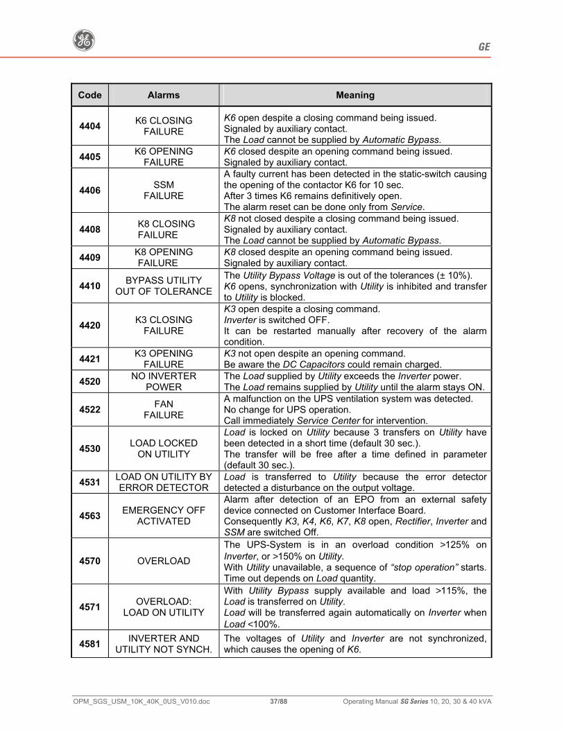
4404 K6 CLOSING FAILURE
K6 open despite a closing command being issued. Signaled by auxiliary contact. The Load cannot be supplied by Automatic Bypass.
4405 K6 OPENING FAILURE
K6 closed despite an opening command being issued. Signaled by auxiliary contact.
4406 SSM FAILURE
A faulty current has been detected in the static-switch causing the opening of the contactor K6 for 10 sec. After 3 times K6 remains definitively open. The alarm reset can be done only from Service.
4408 K8 CLOSING FAILURE
K8 not closed despite a closing command being issued. Signaled by auxiliary contact. The Load cannot be supplied by Automatic Bypass.
4409 K8 OPENING FAILURE
K8 closed despite an opening command being issued. Signaled by auxiliary contact.
4410 BYPASS UTILITY OUT OF TOLERANCE
The Utility Bypass Voltage is out of the tolerances (± 10%). K6 opens, synchronization with Utility is inhibited and transfer to Utility is blocked.
4420 K3 CLOSING FAILURE
K3 open despite a closing command. Inverter is switched OFF. It can be restarted manually after recovery of the alarm condition.
4421 K3 OPENING FAILURE
K3 not open despite an opening command. Be aware the DC Capacitors could remain charged.
4520 NO INVERTER POWER
The Load supplied by Utility exceeds the Inverter power. The Load remains supplied by Utility until the alarm stays ON.
4522 FAN FAILURE
A malfunction on the UPS ventilation system was detected. No change for UPS operation. Call immediately Service Center for intervention.
4530 LOAD LOCKED ON UTILITY
Load is locked on Utility because 3 transfers on Utility have been detected in a short time (default 30 sec.). The transfer will be free after a time defined in parameter (default 30 sec.).
4531 LOAD ON UTILITY BY ERROR DETECTOR
Load is transferred to Utility because the error detector detected a disturbance on the output voltage.
4563 EMERGENCY OFF ACTIVATED
Alarm after detection of an EPO from an external safety device connected on Customer Interface Board. Consequently K3, K4, K6, K7, K8 open, Rectifier, Inverter and SSM are switched Off.
4570 OVERLOAD
The UPS-System is in an overload condition >125% on Inverter, or >150% on Utility. With Utility unavailable, a sequence of “stop operation” starts. Time out depends on Load quantity.
4571 OVERLOAD: LOAD ON UTILITY
With Utility Bypass supply available and load >115%, the Load is transferred on Utility. Load will be transferred again automatically on Inverter when Load <100%.
4581 INVERTER AND UTILITY NOT SYNCH.
The voltages of Utility and Inverter are not synchronized, which causes the opening of K6.
g GE
OPM_SGS_USM_10K_40K_0US_V010.doc 38/88 Operating Manual SG Series 10, 20, 30 & 40 kVA
Code Alarms Meaning
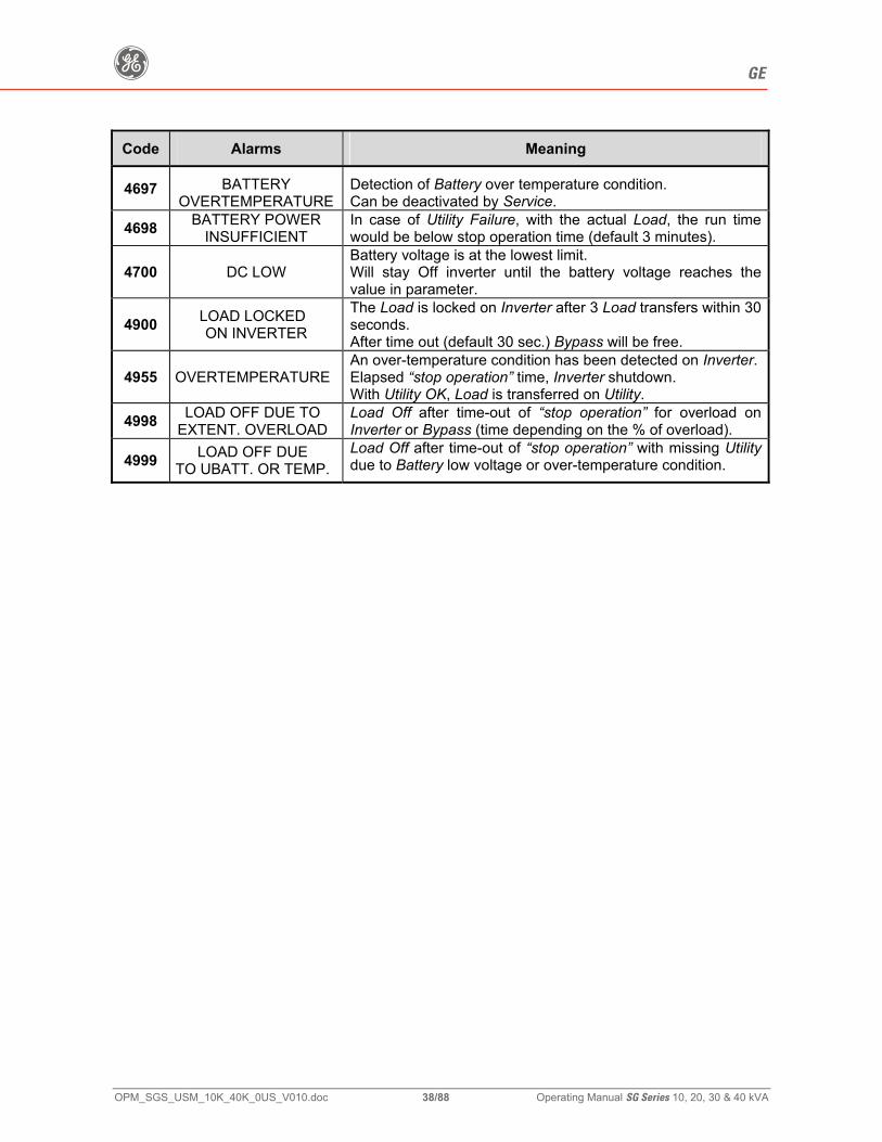
4697 BATTERY OVERTEMPERATURE
Detection of Battery over temperature condition. Can be deactivated by Service.
4698 BATTERY POWER INSUFFICIENT
In case of Utility Failure, with the actual Load, the run time would be below stop operation time (default 3 minutes).
4700 DC LOW Battery voltage is at the lowest limit. Will stay Off inverter until the battery voltage reaches the value in parameter.
4900 LOAD LOCKED ON INVERTER
The Load is locked on Inverter after 3 Load transfers within 30 seconds. After time out (default 30 sec.) Bypass will be free.
4955 OVERTEMPERATURE An over-temperature condition has been detected on Inverter. Elapsed “stop operation” time, Inverter shutdown. With Utility OK, Load is transferred on Utility.
4998 LOAD OFF DUE TO EXTENT. OVERLOAD
Load Off after time-out of “stop operation” for overload on Inverter or Bypass (time depending on the % of overload).
4999 LOAD OFF DUE TO UBATT. OR TEMP.
Load Off after time-out of “stop operation” with missing Utility due to Battery low voltage or over-temperature condition.
g GE
OPM_SGS_USM_10K_40K_0US_V010.doc 39/88 Operating Manual SG Series 10, 20, 30 & 40 kVA
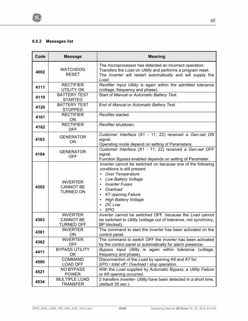
6.6.2 Messages list
Code Message Meaning
4002 WATCHDOG RESET
The microprocessor has detected an incorrect operation: Transfers the Load on Utility and performs a program reset. The Inverter will restart automatically and will supply the Load.
4111 RECTIFIER UTILITY OK
Rectifier Input Utility is again within the admitted tolerance (voltage, frequency and phase).
4119 BATTERY TEST STARTED
Start of Manual or Automatic Battery Test.
4120 BATTERY TEST STOPPED
End of Manual or Automatic Battery Test.
4161 RECTIFIER ON
Rectifier started.
4162 RECTIFIER OFF
Rectifier shutdown.
4163 GENERATOR ON
Customer Interface (X1 - 11, 22) received a Gen-set ON signal. Operating mode depend on setting of Parameters.
4164 GENERATOR OFF
Customer Interface (X1 - 11, 22) received a Gen-set OFF signal. Function Bypass enabled depends on setting of Parameter.
4302 INVERTER
CANNOT BE TURNED ON
Inverter cannot be switched on because one of the following conditions is still present: • Over Temperature • Low Battery Voltage • Inverter Fuses • Overload • K7 opening Failure • High Battery Voltage • DC Low • EPO
4303 INVERTER
CANNOT BE TURNED OFF
Inverter cannot be switched OFF, because the Load cannot be switched to Utility (voltage out of tolerance, not synchrony, BP blocked).
4361 INVERTER ON
The command to start the Inverter has been activated on the control panel.
4362 INVERTER OFF
The command to switch OFF the Inverter has been activated by the control panel or automatically for alarm presence.
4411 BYPASS UTILITY OK
Bypass Input Utility is again within tolerance (voltage, frequency and phase).
4500 COMMAND LOAD OFF
Disconnection of the Load by opening K6 and K7 for: EPO / total off / Overload / stop operation.
4521 NO BYPASS POWER
With the Load supplied by Automatic Bypass, a Utility Failure or K6 opening occurred.
4534 MULTIPLE LOAD TRANSFER
2 transfers Inverter- Utility have been detected in a short time, (default 30 sec.).
g GE
OPM_SGS_USM_10K_40K_0US_V010.doc 40/88 Operating Manual SG Series 10, 20, 30 & 40 kVA
Code Message Meaning
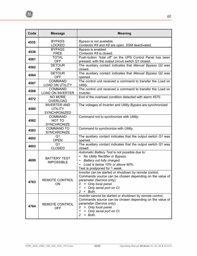
4535 BYPASS LOCKED
Bypass is not available. Contactor K6 and K8 are open, SSM deactivated.
4536 BYPASS FREE
Bypass is enabled. Contactor K6 is closed.
4561 TOTAL OFF
Push-button “total off” on the UPS Control Panel has been pressed, with the output circuit switch Q1 closed.
4562 DETOUR ON
The auxiliary contact indicates that Manual Bypass Q2 was closed.
4564 DETOUR OFF
The auxiliary contact indicates that Manual Bypass Q2 was opened.
4567 COMMAND LOAD ON UTILITY
The control unit received a command to transfer the Load on Utility.
4568 COMMAND LOAD ON INVERTER
The control unit received a command to transfer the Load on Inverter.
4572 NO MORE OVERLOAD
End of the overload condition detected with alarm 4570.
4580 INVERTER AND
UTILITY SYNCHRONIZED
The voltages of Inverter and Utility Bypass are synchronized.
4582 COMMAND
NOT TO SYNCHRONIZE
Command not to synchronize with Utility.
4583 COMMAND TO SYNCHRONIZE
Command to synchronize with Utility.
4602 Q1 OPEN
The auxiliary contact indicates that the output switch Q1 was opened.
4603 Q1 CLOSED
The auxiliary contact indicates that the output switch Q1 was closed.
4699 BATTERY TEST IMPOSSIBLE
Automatic Battery Test is not possible due to: • No Utility Rectifier or Bypass. • Battery not fully charged. • Load is below 10% or above 80%. Test is postponed for 1 week.
4763 REMOTE CONTROL ON
Inverter can be started or shutdown by remote control. Commands source can be chosen depending on the value of parameter (Service only): 0 = Only local panel. 1 = Only serial port on CI. 2 = Both.
4764 REMOTE CONTROL OFF
Inverter cannot be started or shutdown by remote control. Commands source can be chosen depending on the value of parameter (Service only): 0 = Only local panel. 1 = Only serial port on CI. 2 = Both.
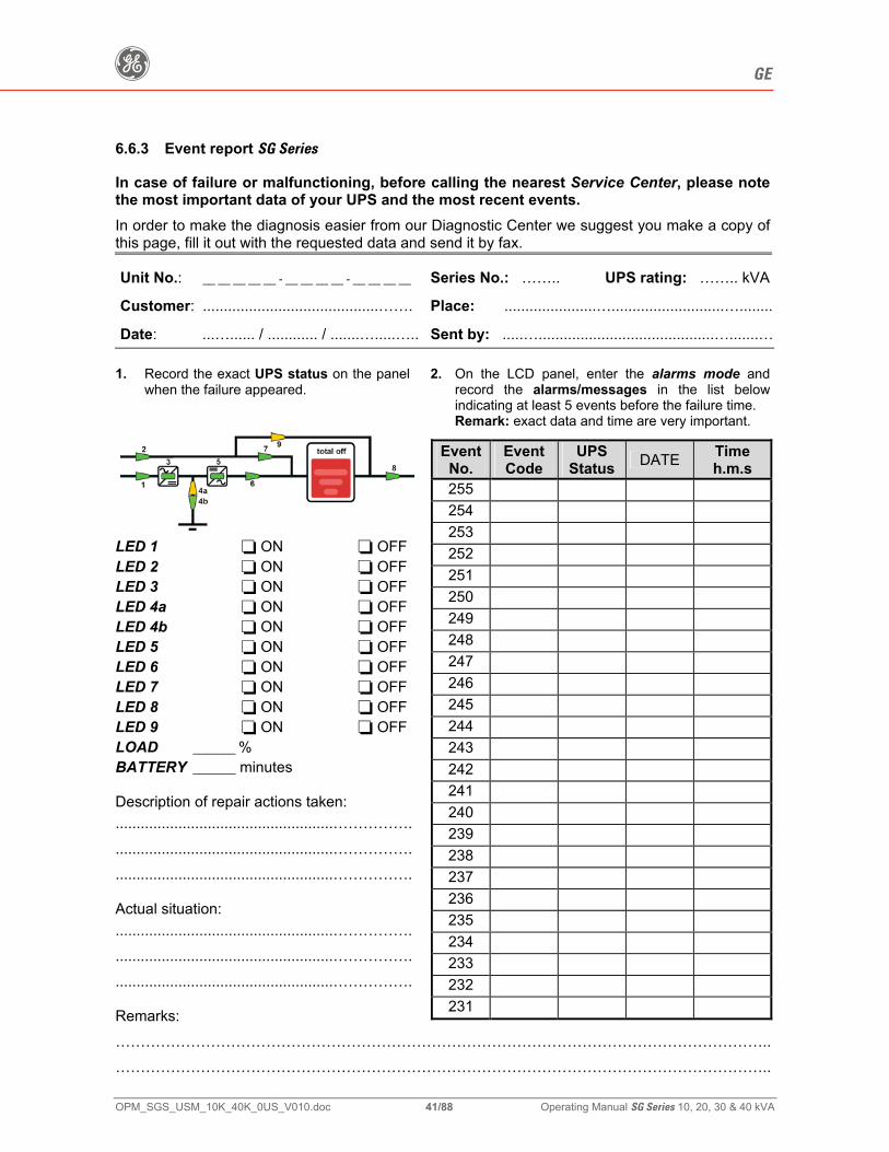
g GE
OPM_SGS_USM_10K_40K_0US_V010.doc 41/88 Operating Manual SG Series 10, 20, 30 & 40 kVA
6.6.3 Event report SG Series
In case of failure or malfunctioning, before calling the nearest Service Center, please note the most important data of your UPS and the most recent events. In order to make the diagnosis easier from our Diagnostic Center we suggest you make a copy of this page, fill it out with the requested data and send it by fax.
Unit No.: __ __ __ __ __ - __ __ __ __ - __ __ __ __ Series No.: …….. UPS rating: …….. kVA
Customer: ..........................................……. Place: ......................…...........................…........
Date: ...…...... / ............ / .......….....….. Sent by: .....…..........................................….......… 1. Record the exact UPS status on the panel
when the failure appeared. 2. On the LCD panel, enter the alarms mode and
record the alarms/messages in the list below indicating at least 5 events before the failure time. Remark: exact data and time are very important.
LED 1 ON OFF LED 2 ON OFF LED 3 ON OFF LED 4a ON OFF LED 4b ON OFF LED 5 ON OFF LED 6 ON OFF LED 7 ON OFF LED 8 ON OFF LED 9 ON OFF LOAD _______ % BATTERY _______ minutes Description of repair actions taken: ....................................................……………. ....................................................……………. ....................................................……………. Actual situation: ....................................................……………. ....................................................……………. ....................................................……………. Remarks: …………………………………………………………………………………………………………………..…………………………………………………………………………………………………………………..
EventNo.
Event Code
UPS Status DATE Time
h.m.s 255 254 253 252 251 250 249 248 247 246 245 244 243 242 241 240 239 238 237 236 235 234 233 232 231

g GE
OPM_SGS_USM_10K_40K_0US_V010.doc 42/88 Operating Manual SG Series 10, 20, 30 & 40 kVA
7 OPERATION
This symbol refers to the operations of a parallel system.
Verify for correct input/output cabling before connecting Utility to the UPS. Open only the front door, do not remove any panels. Now you can initiate the start-up procedure of the UPS system. There is no need for specific knowledge if you follow carefully the step-by-step instructions given below. But we recommend, that at least the initial procedure, should be performed by an instructed person. Check after every step for correct reaction of the UPS (LED’s on the panel), and correct voltage and current measurements, before you proceed to the next step. If you encounter any problems during the following procedures, you should not continue, but contact GE Global Services.
Find on the following pages the descriptions of the various procedures of startup and shutdown for single and parallel UPS’s, divided into the following principal chapters: 7.1 PROCEDURES FOR SINGLE UPS 7.2 PROCEDURES FOR UPS FUNCTIONING AS FREQUENCY CONVERTER 7.3 PROCEDURES FOR PARALLEL SYSTEM 7.4 PROCEDURES FOR PARALLEL SYSTEM WITH COMMON BATTERY
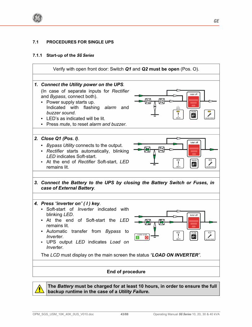
g GE
OPM_SGS_USM_10K_40K_0US_V010.doc 43/88 Operating Manual SG Series 10, 20, 30 & 40 kVA
7.1 PROCEDURES FOR SINGLE UPS
7.1.1 Start-up of the SG Series
Verify with open front door: Switch Q1 and Q2 must be open (Pos. O).
1. Connect the Utility power on the UPS.
(In case of separate inputs for Rectifier and Bypass, connect both). • Power supply starts up.
Indicated with flashing alarm and buzzer sound.
• LED’s as indicated will be lit. • Press mute, to reset alarm and buzzer.
2. Close Q1 (Pos. I).
• Bypass Utility connects to the output. • Rectifier starts automatically, blinking
LED indicates Soft-start. • At the end of Rectifier Soft-start, LED
remains lit. 3. Connect the Battery to the UPS by closing the Battery Switch or Fuses, in
case of External Battery.
4. Press “inverter on” ( I ) key.
• Soft-start of Inverter indicated with blinking LED.
• At the end of Soft-start the LED remains lit.
• Automatic transfer from Bypass to Inverter.
• UPS output LED indicates Load on Inverter.
The LCD must display on the main screen the status “LOAD ON INVERTER”.
End of procedure
The Battery must be charged for at least 10 hours, in order to ensure the full backup runtime in the case of a Utility Failure.
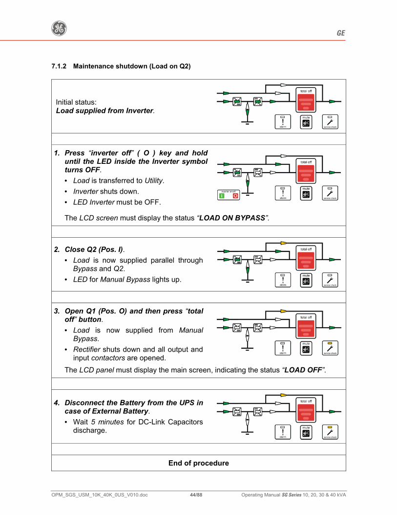
g GE
OPM_SGS_USM_10K_40K_0US_V010.doc 44/88 Operating Manual SG Series 10, 20, 30 & 40 kVA
7.1.2 Maintenance shutdown (Load on Q2)
Initial status: Load supplied from Inverter.
1. Press “inverter off” ( O ) key and hold
until the LED inside the Inverter symbol turns OFF. • Load is transferred to Utility. • Inverter shuts down. • LED Inverter must be OFF.
The LCD screen must display the status “LOAD ON BYPASS”.
2. Close Q2 (Pos. I). • Load is now supplied parallel through
Bypass and Q2. • LED for Manual Bypass lights up.
3. Open Q1 (Pos. O) and then press “total
off” button. • Load is now supplied from Manual
Bypass. • Rectifier shuts down and all output and
input contactors are opened.
The LCD panel must display the main screen, indicating the status “LOAD OFF”.
4. Disconnect the Battery from the UPS in case of External Battery. • Wait 5 minutes for DC-Link Capacitors
discharge.
End of procedure
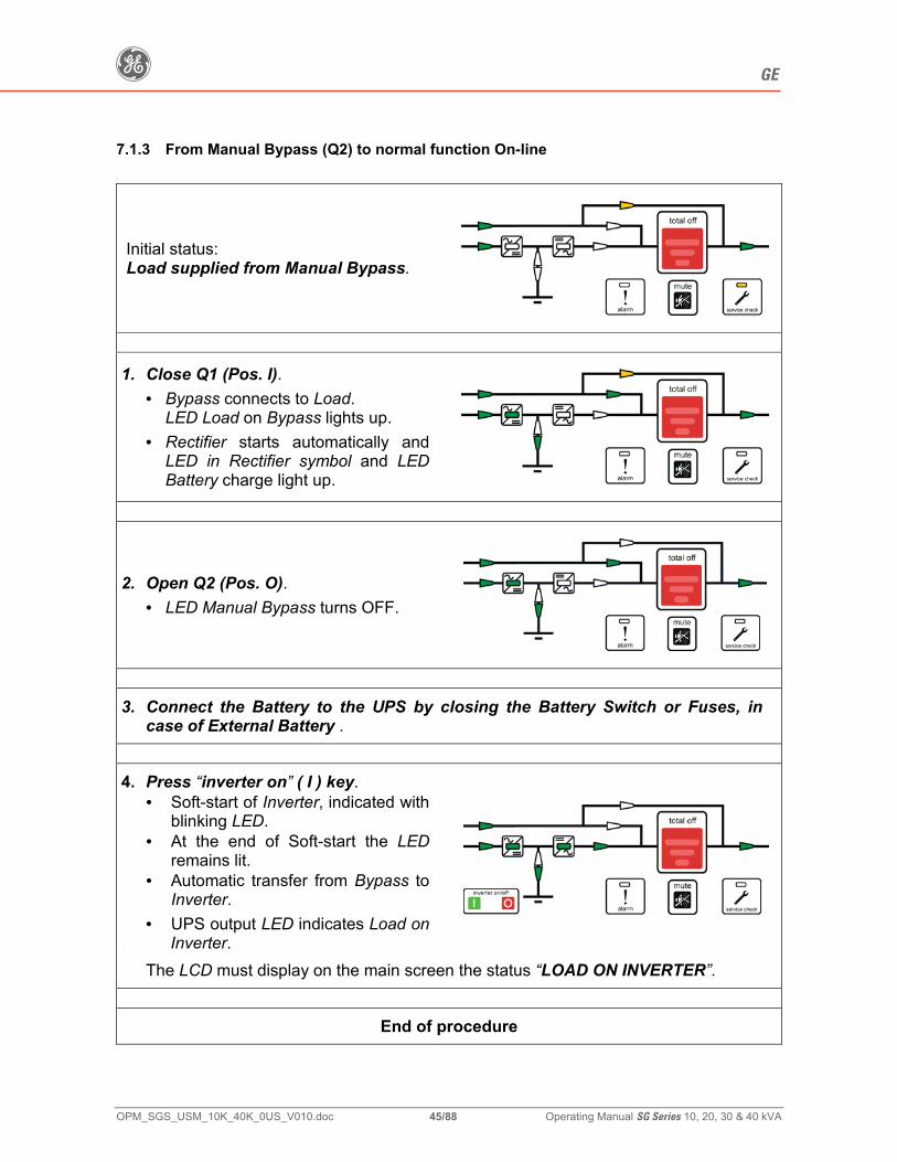
g GE
OPM_SGS_USM_10K_40K_0US_V010.doc 45/88 Operating Manual SG Series 10, 20, 30 & 40 kVA
7.1.3 From Manual Bypass (Q2) to normal function On-line
Initial status: Load supplied from Manual Bypass.
1. Close Q1 (Pos. I). • Bypass connects to Load.
LED Load on Bypass lights up. • Rectifier starts automatically and
LED in Rectifier symbol and LED Battery charge light up.
2. Open Q2 (Pos. O). • LED Manual Bypass turns OFF.
3. Connect the Battery to the UPS by closing the Battery Switch or Fuses, in
case of External Battery . 4. Press “inverter on” ( I ) key.
• Soft-start of Inverter, indicated with blinking LED.
• At the end of Soft-start the LED remains lit.
• Automatic transfer from Bypass to Inverter.
• UPS output LED indicates Load on Inverter.
The LCD must display on the main screen the status “LOAD ON INVERTER”.
End of procedure
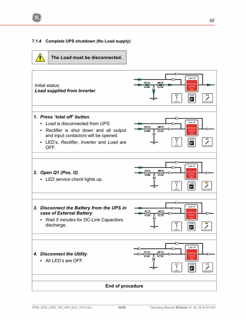
g GE
OPM_SGS_USM_10K_40K_0US_V010.doc 46/88 Operating Manual SG Series 10, 20, 30 & 40 kVA
7.1.4 Complete UPS shutdown (No Load supply)
The Load must be disconnected.
Initial status: Load supplied from Inverter.
1. Press “total off” button.
• Load is disconnected from UPS. • Rectifier is shut down and all output
and input contactors will be opened. • LED’s, Rectifier, Inverter and Load are
OFF.
2. Open Q1 (Pos. O). • LED service check lights up.
3. Disconnect the Battery from the UPS in case of External Battery. • Wait 5 minutes for DC-Link Capacitors
discharge.
4. Disconnect the Utility. • All LED’s are OFF.
End of procedure
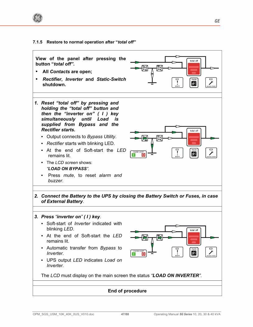
g GE
OPM_SGS_USM_10K_40K_0US_V010.doc 47/88 Operating Manual SG Series 10, 20, 30 & 40 kVA
7.1.5 Restore to normal operation after “total off”
View of the panel after pressing the button “total off”. • All Contacts are open; • Rectifier, Inverter and Static-Switch
shutdown.
1. Reset “total off” by pressing and holding the “total off” button and then the “inverter on” ( I ) key simultaneously until Load is supplied from Bypass and the Rectifier starts. • Output connects to Bypass Utility. • Rectifier starts with blinking LED. • At the end of Soft-start the LED
remains lit. • The LCD screen shows:
“LOAD ON BYPASS”. • Press mute, to reset alarm and
buzzer.
2. Connect the Battery to the UPS by closing the Battery Switch or Fuses, in case of External Battery.
3. Press “inverter on” ( I ) key. • Soft-start of Inverter indicated with
blinking LED. • At the end of Soft-start the LED
remains lit. • Automatic transfer from Bypass to
Inverter. • UPS output LED indicates Load on
Inverter.
The LCD must display on the main screen the status “LOAD ON INVERTER”.
End of procedure
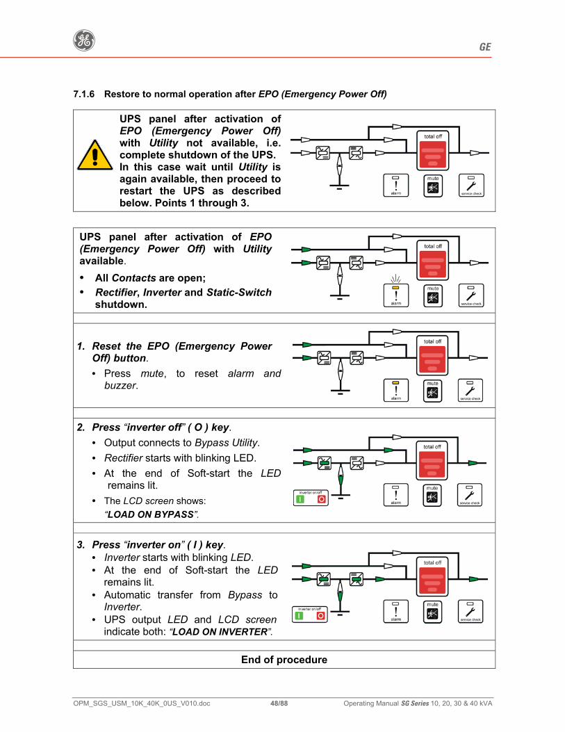
g GE
OPM_SGS_USM_10K_40K_0US_V010.doc 48/88 Operating Manual SG Series 10, 20, 30 & 40 kVA
7.1.6 Restore to normal operation after EPO (Emergency Power Off)
UPS panel after activation of EPO (Emergency Power Off)with Utility not available, i.e. complete shutdown of the UPS. In this case wait until Utility is again available, then proceed to restart the UPS as described below. Points 1 through 3.
UPS panel after activation of EPO (Emergency Power Off) with Utility available. • All Contacts are open; • Rectifier, Inverter and Static-Switch
shutdown.
1. Reset the EPO (Emergency Power Off) button. • Press mute, to reset alarm and
buzzer.
2. Press “inverter off” ( O ) key.
• Output connects to Bypass Utility. • Rectifier starts with blinking LED. • At the end of Soft-start the LED
remains lit. • The LCD screen shows:
“LOAD ON BYPASS”.
3. Press “inverter on” ( I ) key. • Inverter starts with blinking LED. • At the end of Soft-start the LED
remains lit. • Automatic transfer from Bypass to
Inverter. • UPS output LED and LCD screen
indicate both: “LOAD ON INVERTER”.
End of procedure
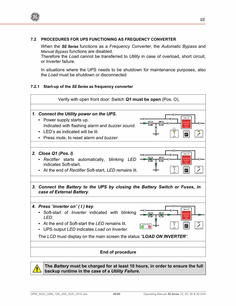
g GE
OPM_SGS_USM_10K_40K_0US_V010.doc 49/88 Operating Manual SG Series 10, 20, 30 & 40 kVA
7.2 PROCEDURES FOR UPS FUNCTIONING AS FREQUENCY CONVERTER
When the SG Series functions as a Frequency Converter, the Automatic Bypass and Manual Bypass functions are disabled. Therefore the Load cannot be transferred to Utility in case of overload, short circuit, or Inverter failure. In situations where the UPS needs to be shutdown for maintenance purposes, also the Load must be shutdown or disconnected
7.2.1 Start-up of the SG Series as frequency converter
Verify with open front door: Switch Q1 must be open (Pos. O).
1. Connect the Utility power on the UPS.
• Power supply starts up. Indicated with flashing alarm and buzzer sound.
• LED’s as indicated will be lit. • Press mute, to reset alarm and buzzer.
2. Close Q1 (Pos. I).
• Rectifier starts automatically, blinking LED indicates Soft-start.
• At the end of Rectifier Soft-start, LED remains lit.
3. Connect the Battery to the UPS by closing the Battery Switch or Fuses, in
case of External Battery.
4. Press “inverter on” ( I ) key.
• Soft-start of Inverter indicated with blinking LED.
• At the end of Soft-start the LED remains lit. • UPS output LED indicates Load on Inverter. The LCD must display on the main screen the status “LOAD ON INVERTER”.
End of procedure
The Battery must be charged for at least 10 hours, in order to ensure the full backup runtime in the case of a Utility Failure.
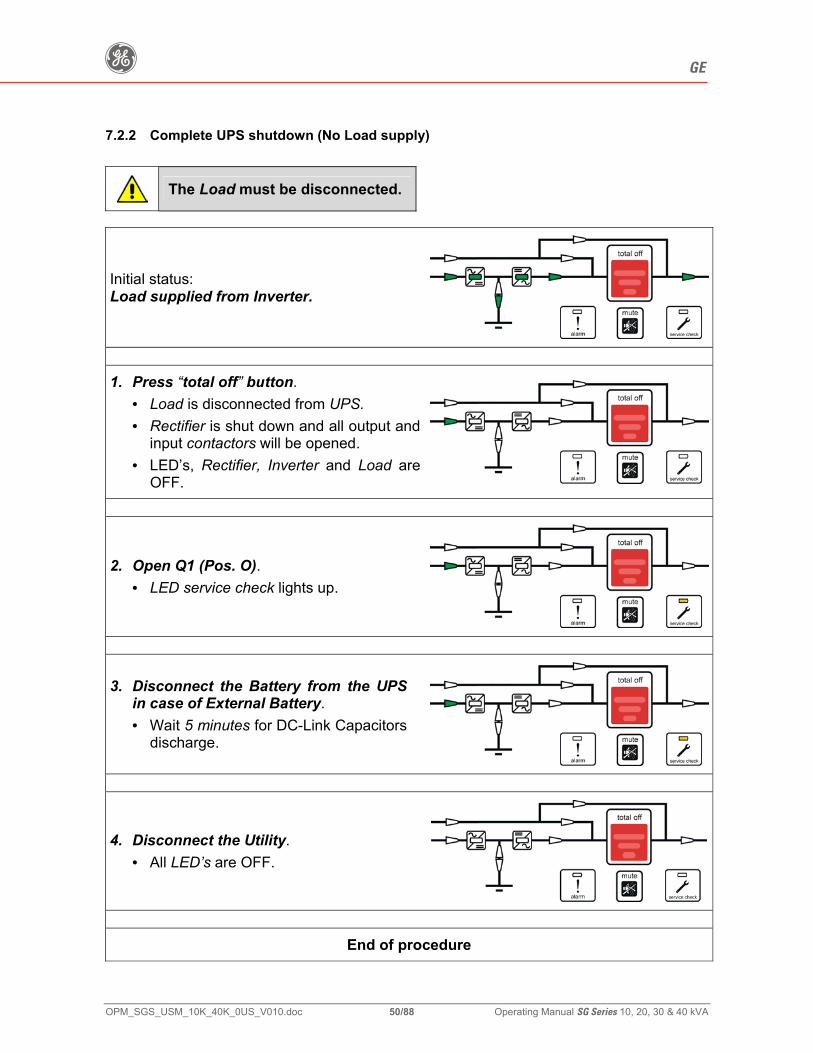
g GE
OPM_SGS_USM_10K_40K_0US_V010.doc 50/88 Operating Manual SG Series 10, 20, 30 & 40 kVA
7.2.2 Complete UPS shutdown (No Load supply)
The Load must be disconnected.
Initial status: Load supplied from Inverter.
1. Press “total off” button.
• Load is disconnected from UPS. • Rectifier is shut down and all output and
input contactors will be opened. • LED’s, Rectifier, Inverter and Load are
OFF.
2. Open Q1 (Pos. O). • LED service check lights up.
3. Disconnect the Battery from the UPS in case of External Battery. • Wait 5 minutes for DC-Link Capacitors
discharge.
4. Disconnect the Utility. • All LED’s are OFF.
End of procedure
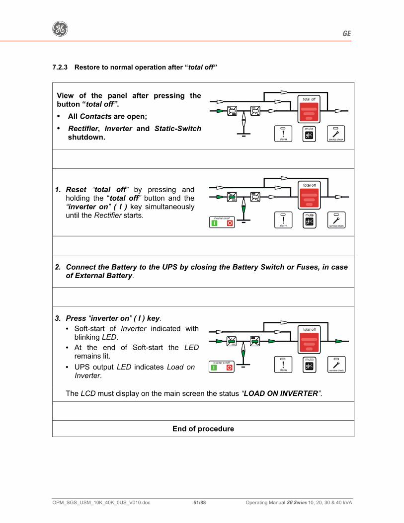
g GE
OPM_SGS_USM_10K_40K_0US_V010.doc 51/88 Operating Manual SG Series 10, 20, 30 & 40 kVA
7.2.3 Restore to normal operation after “total off”
View of the panel after pressing the button “total off”. • All Contacts are open; • Rectifier, Inverter and Static-Switch
shutdown.
1. Reset “total off” by pressing and
holding the “total off” button and the “inverter on” ( I ) key simultaneously until the Rectifier starts.
2. Connect the Battery to the UPS by closing the Battery Switch or Fuses, in case
of External Battery.
3. Press “inverter on” ( I ) key.
• Soft-start of Inverter indicated with blinking LED.
• At the end of Soft-start the LED remains lit.
• UPS output LED indicates Load on Inverter.
The LCD must display on the main screen the status “LOAD ON INVERTER”.
End of procedure
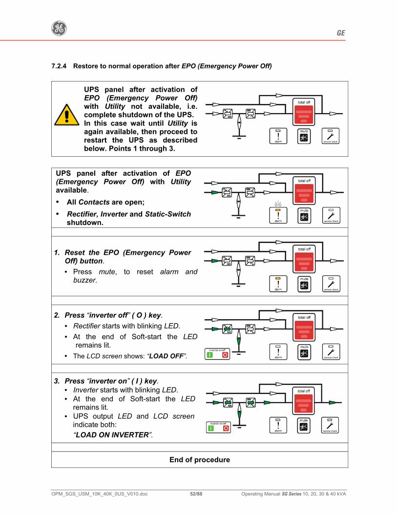
g GE
OPM_SGS_USM_10K_40K_0US_V010.doc 52/88 Operating Manual SG Series 10, 20, 30 & 40 kVA
7.2.4 Restore to normal operation after EPO (Emergency Power Off)
UPS panel after activation of EPO (Emergency Power Off)with Utility not available, i.e. complete shutdown of the UPS. In this case wait until Utility is again available, then proceed to restart the UPS as described below. Points 1 through 3.
UPS panel after activation of EPO (Emergency Power Off) with Utility available. • All Contacts are open; • Rectifier, Inverter and Static-Switch
shutdown.
1. Reset the EPO (Emergency Power Off) button. • Press mute, to reset alarm and
buzzer.
2. Press “inverter off” ( O ) key. • Rectifier starts with blinking LED. • At the end of Soft-start the LED
remains lit. • The LCD screen shows: “LOAD OFF”.
3. Press “inverter on” ( I ) key.
• Inverter starts with blinking LED. • At the end of Soft-start the LED
remains lit. • UPS output LED and LCD screen
indicate both: “LOAD ON INVERTER”.
End of procedure
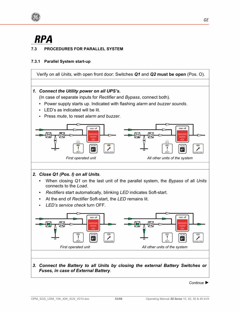
g GE
OPM_SGS_USM_10K_40K_0US_V010.doc 53/88 Operating Manual SG Series 10, 20, 30 & 40 kVA
7.3 PROCEDURES FOR PARALLEL SYSTEM
7.3.1 Parallel System start-up
Verify on all Units, with open front door: Switches Q1 and Q2 must be open (Pos. O).
1. Connect the Utility power on all UPS’s.
(In case of separate inputs for Rectifier and Bypass, connect both). • Power supply starts up. Indicated with flashing alarm and buzzer sounds. • LED’s as indicated will be lit. • Press mute, to reset alarm and buzzer.
First operated unit All other units of the system
2. Close Q1 (Pos. I) on all Units.
• When closing Q1 on the last unit of the parallel system, the Bypass of all Units connects to the Load.
• Rectifiers start automatically, blinking LED indicates Soft-start. • At the end of Rectifier Soft-start, the LED remains lit. • LED’s service check turn OFF.
First operated unit All other units of the system
3. Connect the Battery to all Units by closing the external Battery Switches or Fuses, in case of External Battery.
Continue ►
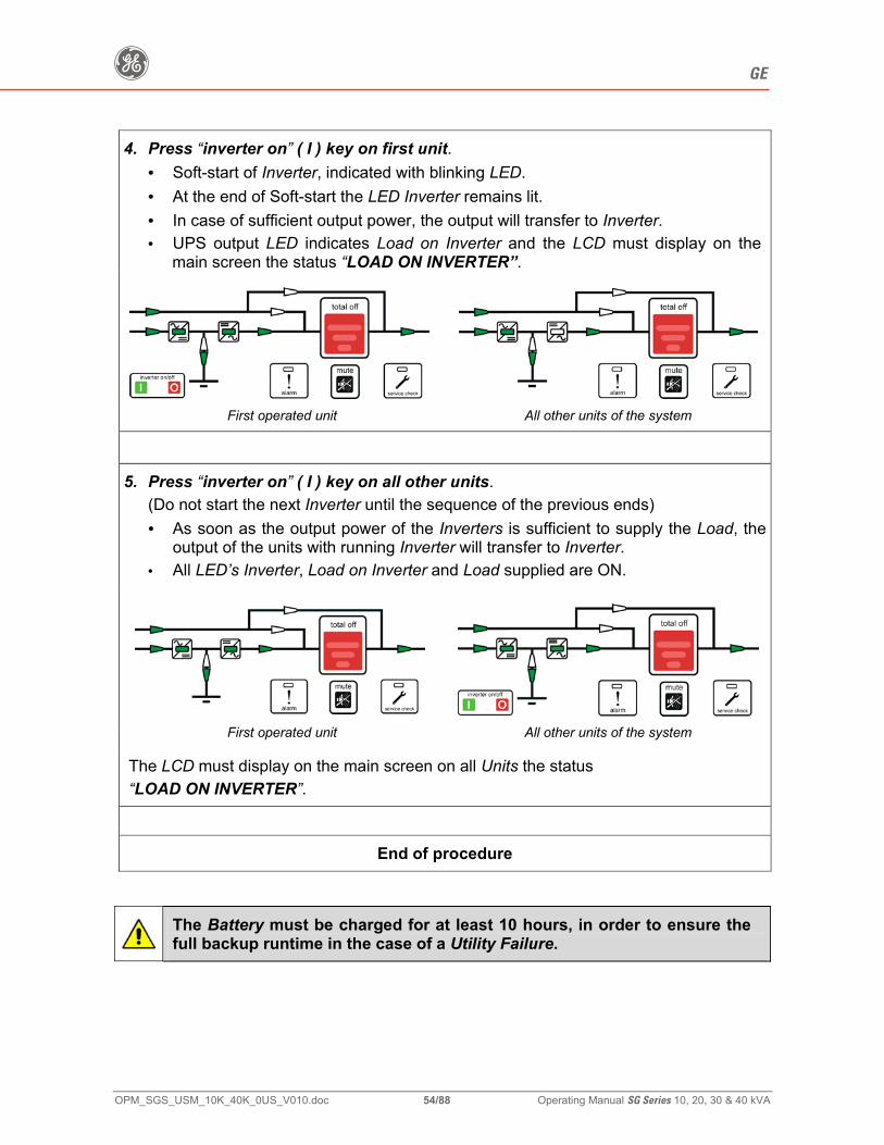
g GE
OPM_SGS_USM_10K_40K_0US_V010.doc 54/88 Operating Manual SG Series 10, 20, 30 & 40 kVA
4. Press “inverter on” ( I ) key on first unit. • Soft-start of Inverter, indicated with blinking LED. • At the end of Soft-start the LED Inverter remains lit. • In case of sufficient output power, the output will transfer to Inverter. • UPS output LED indicates Load on Inverter and the LCD must display on the
main screen the status “LOAD ON INVERTER”.
First operated unit All other units of the system
5. Press “inverter on” ( I ) key on all other units.
(Do not start the next Inverter until the sequence of the previous ends) • As soon as the output power of the Inverters is sufficient to supply the Load, the
output of the units with running Inverter will transfer to Inverter. • All LED’s Inverter, Load on Inverter and Load supplied are ON.
First operated unit All other units of the system
The LCD must display on the main screen on all Units the status “LOAD ON INVERTER”.
End of procedure
The Battery must be charged for at least 10 hours, in order to ensure the full backup runtime in the case of a Utility Failure.
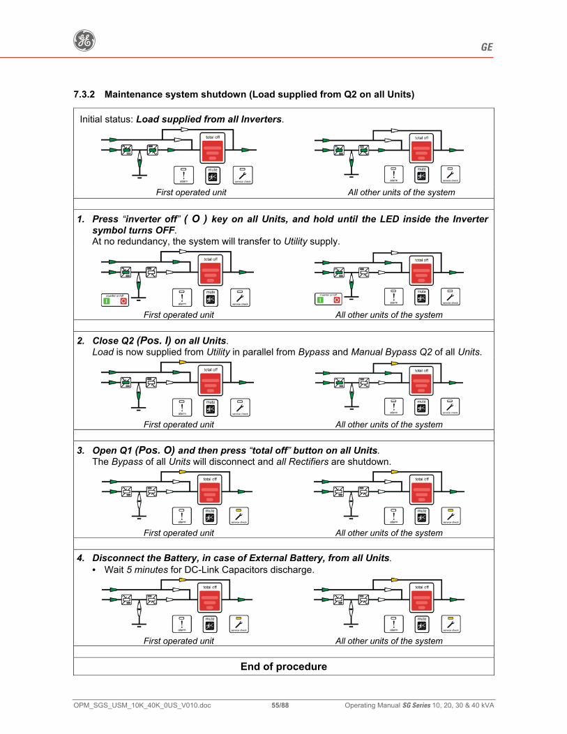
g GE
OPM_SGS_USM_10K_40K_0US_V010.doc 55/88 Operating Manual SG Series 10, 20, 30 & 40 kVA
7.3.2 Maintenance system shutdown (Load supplied from Q2 on all Units)
Initial status: Load supplied from all Inverters.
First operated unit All other units of the system
1. Press “inverter off” ( O ) key on all Units, and hold until the LED inside the Inverter
symbol turns OFF. At no redundancy, the system will transfer to Utility supply.
First operated unit All other units of the system
2. Close Q2 (Pos. I) on all Units.
Load is now supplied from Utility in parallel from Bypass and Manual Bypass Q2 of all Units.
First operated unit All other units of the system
3. Open Q1 (Pos. O) and then press “total off” button on all Units.
The Bypass of all Units will disconnect and all Rectifiers are shutdown.
First operated unit All other units of the system
4. Disconnect the Battery, in case of External Battery, from all Units.
• Wait 5 minutes for DC-Link Capacitors discharge.
First operated unit All other units of the system
End of procedure
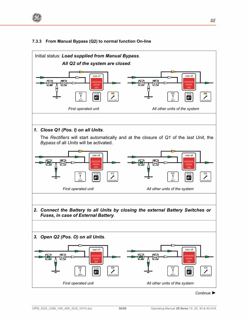
g GE
OPM_SGS_USM_10K_40K_0US_V010.doc 56/88 Operating Manual SG Series 10, 20, 30 & 40 kVA
7.3.3 From Manual Bypass (Q2) to normal function On-line
Initial status: Load supplied from Manual Bypass. All Q2 of the system are closed.
First operated unit All other units of the system
1. Close Q1 (Pos. I) on all Units.
The Rectifiers will start automatically and at the closure of Q1 of the last Unit, the Bypass of all Units will be activated.
First operated unit All other units of the system
2. Connect the Battery to all Units by closing the external Battery Switches or
Fuses, in case of External Battery.
3. Open Q2 (Pos. O) on all Units.
First operated unit All other units of the system
Continue ►
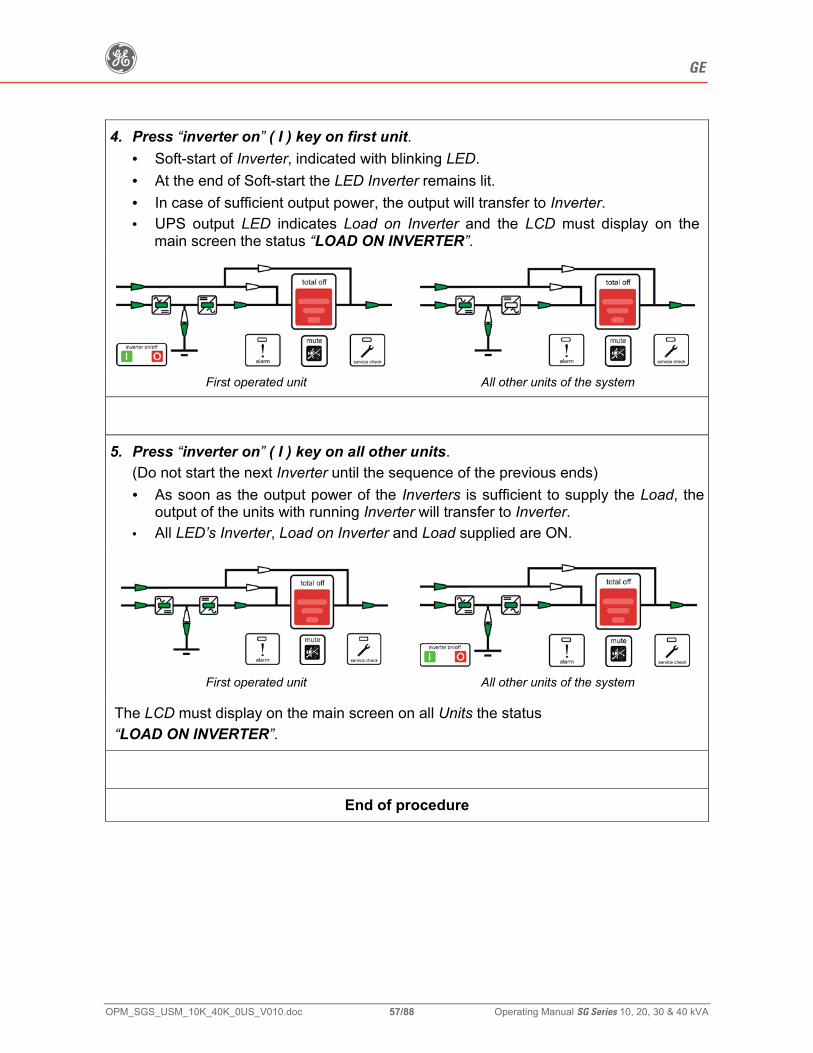
g GE
OPM_SGS_USM_10K_40K_0US_V010.doc 57/88 Operating Manual SG Series 10, 20, 30 & 40 kVA
4. Press “inverter on” ( I ) key on first unit. • Soft-start of Inverter, indicated with blinking LED. • At the end of Soft-start the LED Inverter remains lit. • In case of sufficient output power, the output will transfer to Inverter. • UPS output LED indicates Load on Inverter and the LCD must display on the
main screen the status “LOAD ON INVERTER”.
First operated unit All other units of the system
5. Press “inverter on” ( I ) key on all other units.
(Do not start the next Inverter until the sequence of the previous ends) • As soon as the output power of the Inverters is sufficient to supply the Load, the
output of the units with running Inverter will transfer to Inverter. • All LED’s Inverter, Load on Inverter and Load supplied are ON.
First operated unit All other units of the system
The LCD must display on the main screen on all Units the status “LOAD ON INVERTER”.
End of procedure
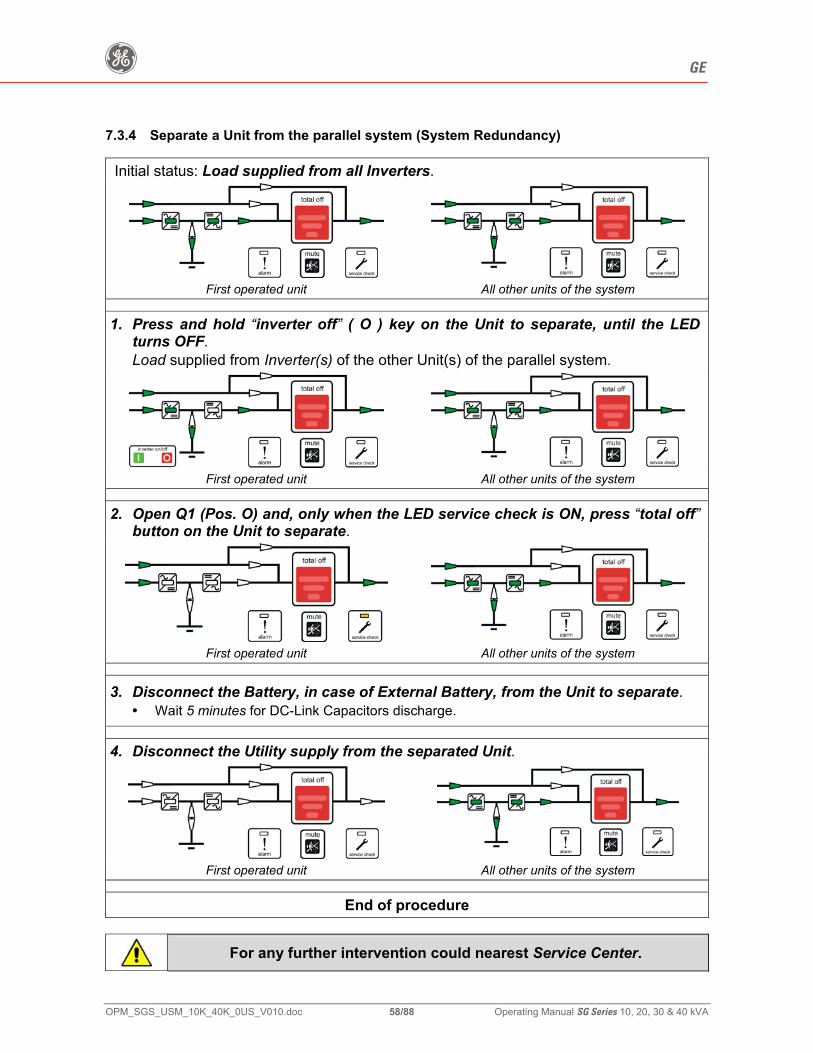
g GE
OPM_SGS_USM_10K_40K_0US_V010.doc 58/88 Operating Manual SG Series 10, 20, 30 & 40 kVA
7.3.4 Separate a Unit from the parallel system (System Redundancy)
Initial status: Load supplied from all Inverters.
First operated unit All other units of the system
1. Press and hold “inverter off” ( O ) key on the Unit to separate, until the LED turns OFF. Load supplied from Inverter(s) of the other Unit(s) of the parallel system.
First operated unit All other units of the system
2. Open Q1 (Pos. O) and, only when the LED service check is ON, press “total off” button on the Unit to separate.
First operated unit All other units of the system
3. Disconnect the Battery, in case of External Battery, from the Unit to separate. • Wait 5 minutes for DC-Link Capacitors discharge.
4. Disconnect the Utility supply from the separated Unit.
First operated unit All other units of the system
End of procedure
For any further intervention could nearest Service Center.
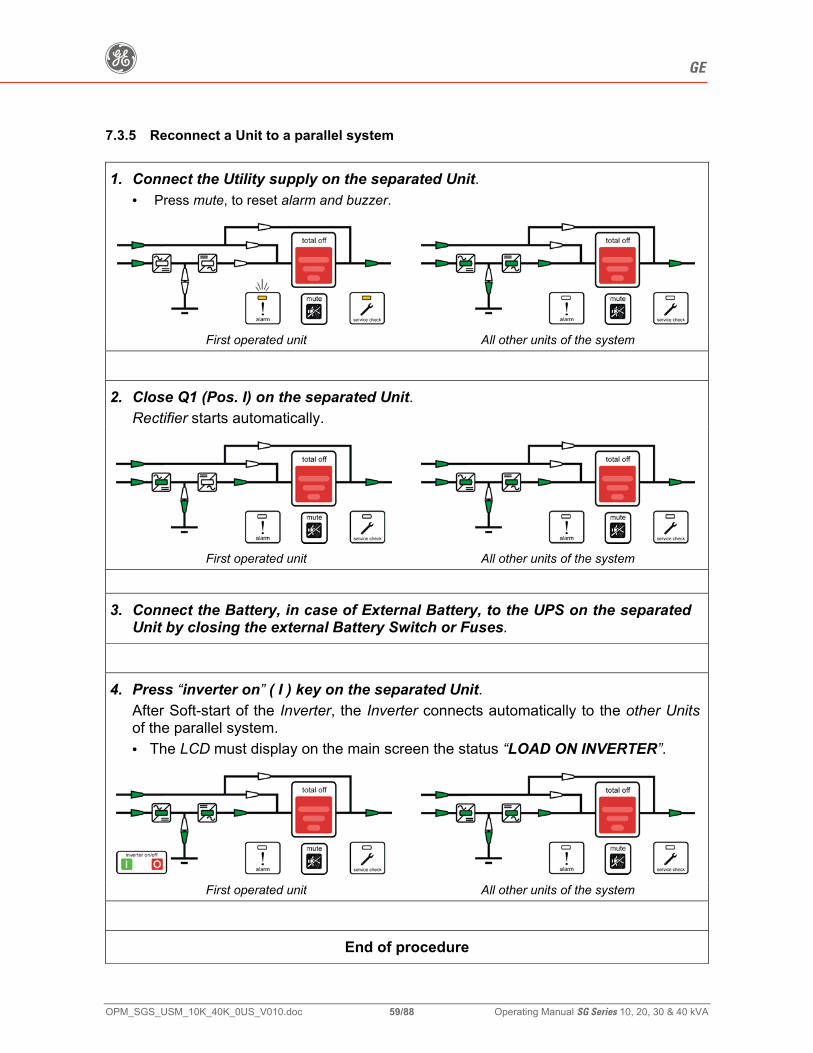
g GE
OPM_SGS_USM_10K_40K_0US_V010.doc 59/88 Operating Manual SG Series 10, 20, 30 & 40 kVA
7.3.5 Reconnect a Unit to a parallel system
1. Connect the Utility supply on the separated Unit. • Press mute, to reset alarm and buzzer.
First operated unit All other units of the system
2. Close Q1 (Pos. I) on the separated Unit.
Rectifier starts automatically.
First operated unit All other units of the system
3. Connect the Battery, in case of External Battery, to the UPS on the separated
Unit by closing the external Battery Switch or Fuses.
4. Press “inverter on” ( I ) key on the separated Unit. After Soft-start of the Inverter, the Inverter connects automatically to the other Units of the parallel system. • The LCD must display on the main screen the status “LOAD ON INVERTER”.
First operated unit All other units of the system
End of procedure
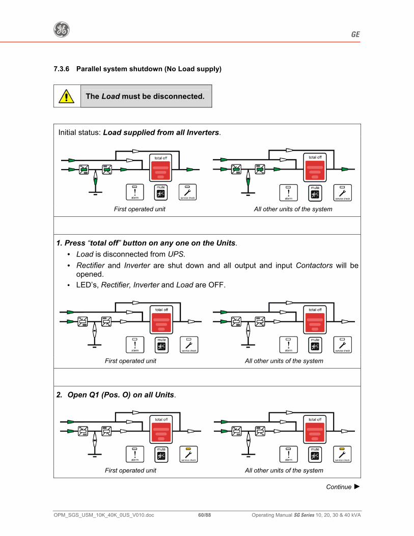
g GE
OPM_SGS_USM_10K_40K_0US_V010.doc 60/88 Operating Manual SG Series 10, 20, 30 & 40 kVA
7.3.6 Parallel system shutdown (No Load supply)
The Load must be disconnected.
Initial status: Load supplied from all Inverters.
First operated unit All other units of the system
1. Press “total off” button on any one on the Units.
• Load is disconnected from UPS. • Rectifier and Inverter are shut down and all output and input Contactors will be
opened. • LED’s, Rectifier, Inverter and Load are OFF.
First operated unit All other units of the system
2. Open Q1 (Pos. O) on all Units.
First operated unit All other units of the system
Continue ►
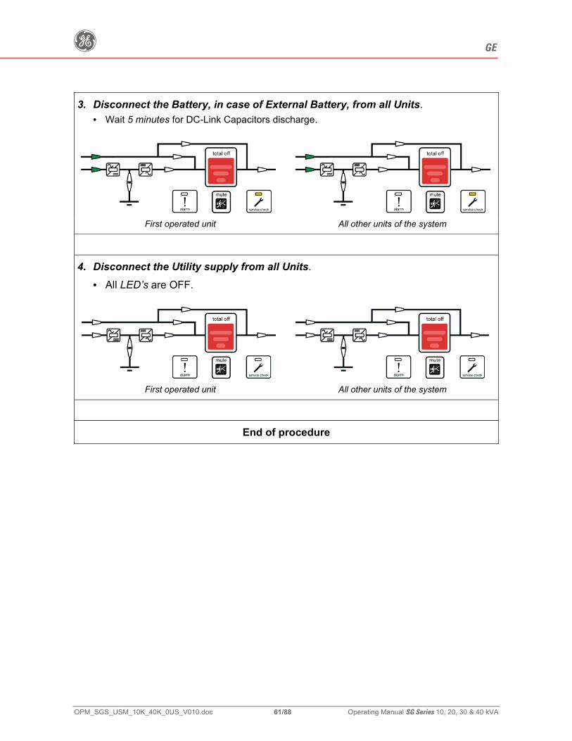
g GE
OPM_SGS_USM_10K_40K_0US_V010.doc 61/88 Operating Manual SG Series 10, 20, 30 & 40 kVA
3. Disconnect the Battery, in case of External Battery, from all Units. • Wait 5 minutes for DC-Link Capacitors discharge.
First operated unit All other units of the system
4. Disconnect the Utility supply from all Units.
• All LED’s are OFF.
First operated unit All other units of the system
End of procedure
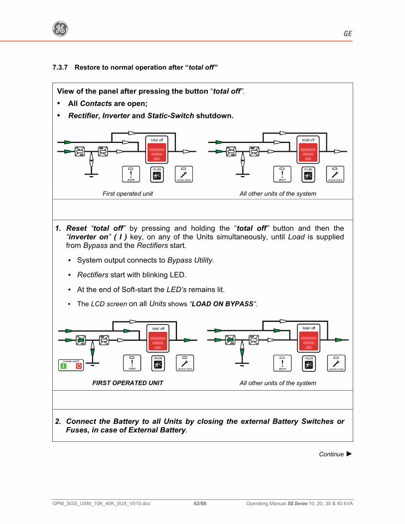
g GE
OPM_SGS_USM_10K_40K_0US_V010.doc 62/88 Operating Manual SG Series 10, 20, 30 & 40 kVA
7.3.7 Restore to normal operation after “total off”
View of the panel after pressing the button “total off”. • All Contacts are open; • Rectifier, Inverter and Static-Switch shutdown.
First operated unit All other units of the system
1. Reset “total off” by pressing and holding the “total off” button and then the
“inverter on” ( I ) key, on any of the Units simultaneously, until Load is supplied from Bypass and the Rectifiers start.
• System output connects to Bypass Utility.
• Rectifiers start with blinking LED.
• At the end of Soft-start the LED’s remains lit.
• The LCD screen on all Units shows “LOAD ON BYPASS”.
FIRST OPERATED UNIT All other units of the system
2. Connect the Battery to all Units by closing the external Battery Switches or
Fuses, in case of External Battery.
Continue ►

g GE
OPM_SGS_USM_10K_40K_0US_V010.doc 63/88 Operating Manual SG Series 10, 20, 30 & 40 kVA
3 Press “inverter on” ( I ) key on first unit. • Soft-start of Inverter, indicated with blinking LED. • At the end of Soft-start the LED Inverter remains lit. • In case of sufficient output power, the output will transfer to Inverter. • UPS output LED indicates Load on Inverter and the LCD must display on the
main screen the status “LOAD ON INVERTER”.
First operated unit All other units of the system
4. Press “inverter on” ( I ) key on all other units.
(Do not start the next Inverter until the sequence of the previous ends) • As soon as the output power of the Inverters is sufficient to supply the Load, the
output of the units with running Inverter will transfer to Inverter. • All LED’s Inverter, Load on Inverter and Load supplied are ON.
First operated unit All other units of the system
The LCD must display on the main screen on all Units the status “LOAD ON INVERTER””.
End of procedure
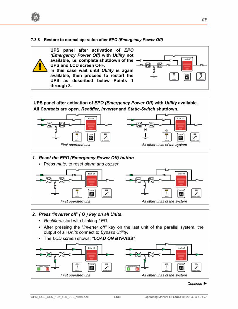
g GE
OPM_SGS_USM_10K_40K_0US_V010.doc 64/88 Operating Manual SG Series 10, 20, 30 & 40 kVA
7.3.8 Restore to normal operation after EPO (Emergency Power Off)
UPS panel after activation of EPO(Emergency Power Off) with Utility not available, i.e. complete shutdown of the UPS and LCD screen OFF. In this case wait until Utility is again available, then proceed to restart the UPS as described below Points 1 through 3.
UPS panel after activation of EPO (Emergency Power Off) with Utility available. All Contacts are open. Rectifier, Inverter and Static-Switch shutdown.
First operated unit All other units of the system
1. Reset the EPO (Emergency Power Off) button. • Press mute, to reset alarm and buzzer.
First operated unit All other units of the system
2. Press “inverter off” ( O ) key on all Units. • Rectifiers start with blinking LED. • After pressing the “inverter off” key on the last unit of the parallel system, the
output of all Units connect to Bypass Utility. • The LCD screen shows: “LOAD ON BYPASS”.
First operated unit All other units of the system
Continue ►
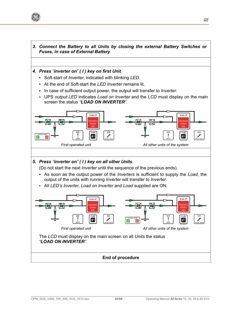
g GE
OPM_SGS_USM_10K_40K_0US_V010.doc 65/88 Operating Manual SG Series 10, 20, 30 & 40 kVA
3. Connect the Battery to all Units by closing the external Battery Switches or Fuses, in case of External Battery.
4. Press “inverter on” ( I ) key on first Unit.
• Soft-start of Inverter, indicated with blinking LED. • At the end of Soft-start the LED Inverter remains lit. • In case of sufficient output power, the output will transfer to Inverter. • UPS output LED indicates Load on Inverter and the LCD must display on the main
screen the status “LOAD ON INVERTER”.
First operated unit All other units of the system
5. Press “inverter on” ( I ) key on all other Units.
(Do not start the next Inverter until the sequence of the previous ends). • As soon as the output power of the Inverters is sufficient to supply the Load, the
output of the units with running Inverter will transfer to Inverter. • All LED’s Inverter, Load on Inverter and Load supplied are ON.
First operated unit All other units of the system
The LCD must display on the main screen on all Units the status “LOAD ON INVERTER”.
End of procedure
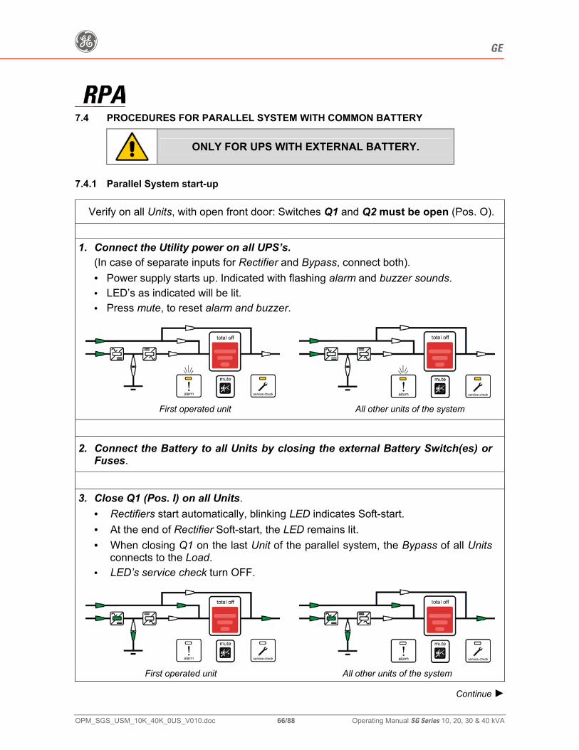
g GE
OPM_SGS_USM_10K_40K_0US_V010.doc 66/88 Operating Manual SG Series 10, 20, 30 & 40 kVA
7.4 PROCEDURES FOR PARALLEL SYSTEM WITH COMMON BATTERY
ONLY FOR UPS WITH EXTERNAL BATTERY.
7.4.1 Parallel System start-up
Verify on all Units, with open front door: Switches Q1 and Q2 must be open (Pos. O).
1. Connect the Utility power on all UPS’s.
(In case of separate inputs for Rectifier and Bypass, connect both). • Power supply starts up. Indicated with flashing alarm and buzzer sounds. • LED’s as indicated will be lit. • Press mute, to reset alarm and buzzer.
First operated unit All other units of the system
2. Connect the Battery to all Units by closing the external Battery Switch(es) or
Fuses.
3. Close Q1 (Pos. I) on all Units.
• Rectifiers start automatically, blinking LED indicates Soft-start. • At the end of Rectifier Soft-start, the LED remains lit. • When closing Q1 on the last Unit of the parallel system, the Bypass of all Units
connects to the Load. • LED’s service check turn OFF.
First operated unit All other units of the system
Continue ►
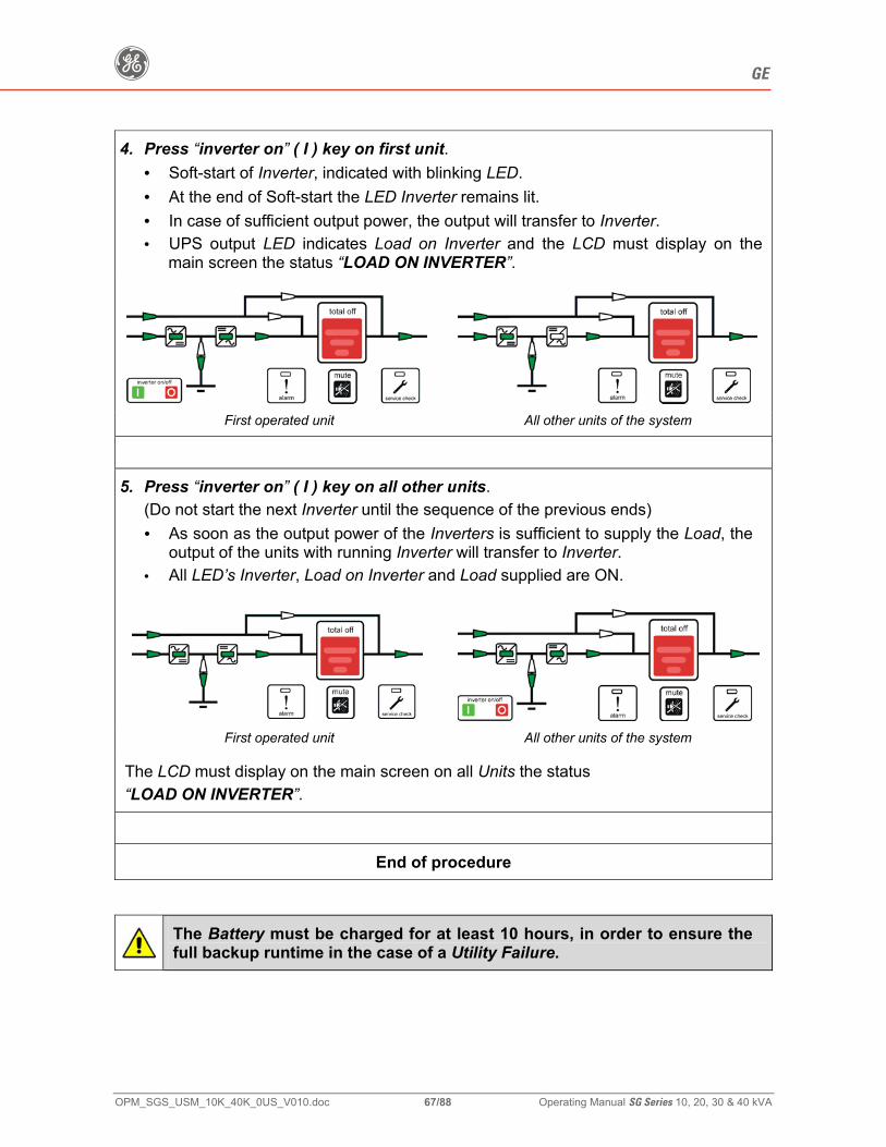
g GE
OPM_SGS_USM_10K_40K_0US_V010.doc 67/88 Operating Manual SG Series 10, 20, 30 & 40 kVA
4. Press “inverter on” ( I ) key on first unit. • Soft-start of Inverter, indicated with blinking LED. • At the end of Soft-start the LED Inverter remains lit. • In case of sufficient output power, the output will transfer to Inverter. • UPS output LED indicates Load on Inverter and the LCD must display on the
main screen the status “LOAD ON INVERTER”.
First operated unit All other units of the system
5. Press “inverter on” ( I ) key on all other units.
(Do not start the next Inverter until the sequence of the previous ends) • As soon as the output power of the Inverters is sufficient to supply the Load, the
output of the units with running Inverter will transfer to Inverter. • All LED’s Inverter, Load on Inverter and Load supplied are ON.
First operated unit All other units of the system
The LCD must display on the main screen on all Units the status “LOAD ON INVERTER”.
End of procedure
The Battery must be charged for at least 10 hours, in order to ensure the full backup runtime in the case of a Utility Failure.
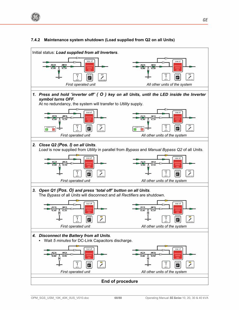
g GE
OPM_SGS_USM_10K_40K_0US_V010.doc 68/88 Operating Manual SG Series 10, 20, 30 & 40 kVA
7.4.2 Maintenance system shutdown (Load supplied from Q2 on all Units)
Initial status: Load supplied from all Inverters.
First operated unit All other units of the system
1. Press and hold “inverter off” ( O ) key on all Units, until the LED inside the Inverter symbol turns OFF. At no redundancy, the system will transfer to Utility supply.
First operated unit All other units of the system
2. Close Q2 (Pos. I) on all Units. Load is now supplied from Utility in parallel from Bypass and Manual Bypass Q2 of all Units.
First operated unit All other units of the system
3. Open Q1 (Pos. O) and press “total off” button on all Units. The Bypass of all Units will disconnect and all Rectifiers are shutdown.
First operated unit All other units of the system
4. Disconnect the Battery from all Units. • Wait 5 minutes for DC-Link Capacitors discharge.
First operated unit All other units of the system
End of procedure
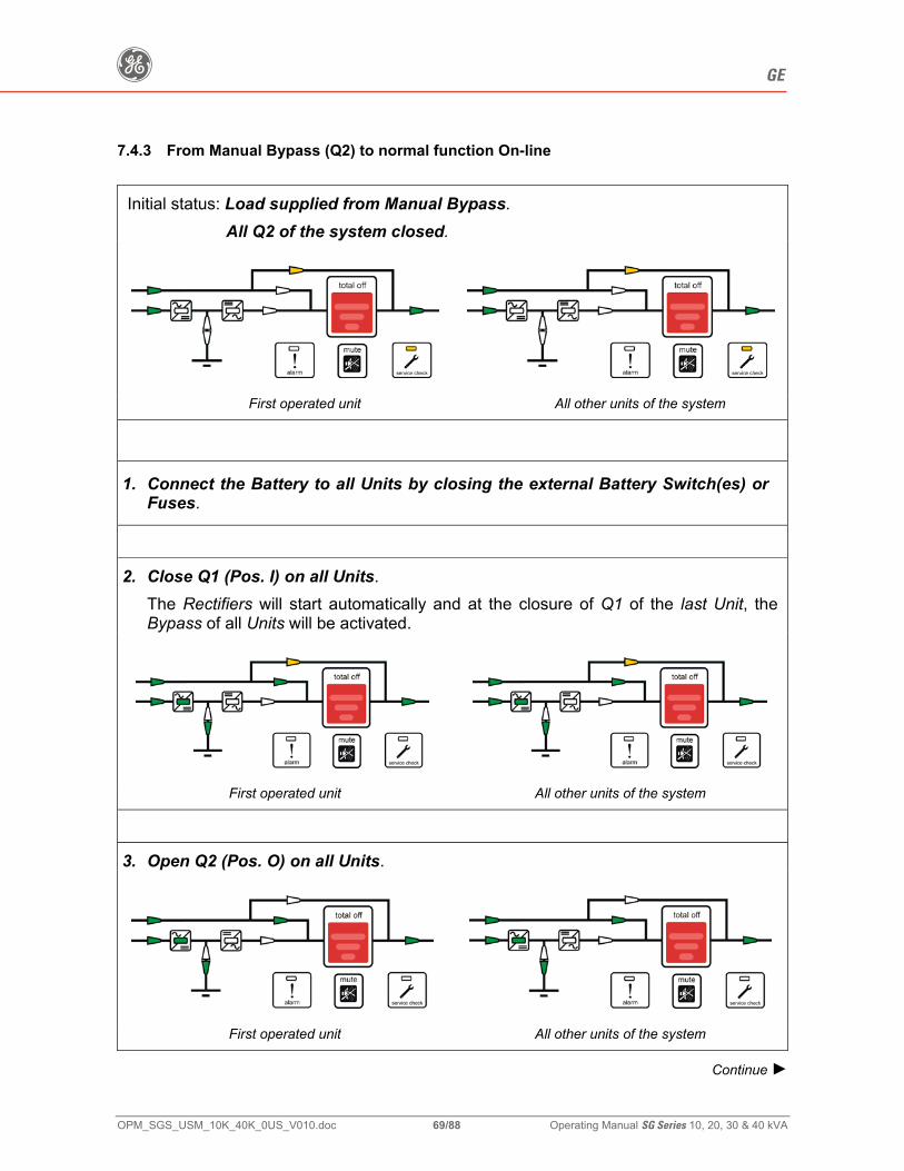
g GE
OPM_SGS_USM_10K_40K_0US_V010.doc 69/88 Operating Manual SG Series 10, 20, 30 & 40 kVA
7.4.3 From Manual Bypass (Q2) to normal function On-line
Initial status: Load supplied from Manual Bypass. All Q2 of the system closed.
First operated unit All other units of the system
1. Connect the Battery to all Units by closing the external Battery Switch(es) or
Fuses.
2. Close Q1 (Pos. I) on all Units.
The Rectifiers will start automatically and at the closure of Q1 of the last Unit, the Bypass of all Units will be activated.
First operated unit All other units of the system
3. Open Q2 (Pos. O) on all Units.
First operated unit All other units of the system
Continue ►

g GE
OPM_SGS_USM_10K_40K_0US_V010.doc 70/88 Operating Manual SG Series 10, 20, 30 & 40 kVA
4. Press “inverter on” ( I ) key on first unit. • Soft-start of Inverter, indicated with blinking LED. • At the end of Soft-start the LED Inverter remains lit. • In case of sufficient output power, the output will transfer to Inverter. • UPS output LED indicates Load on Inverter and the LCD must display on the
main screen the status “LOAD ON INVERTER”.
First operated unit All other units of the system
5. Press “inverter on” ( I ) key on all other units.
(Do not start the next Inverter until the sequence of the previous ends) • As soon as the output power of the Inverters is sufficient to supply the Load, the
output of the units with running Inverter will transfer to Inverter. • All LED’s Inverter, Load on Inverter and Load supplied are ON.
First operated unit All other units of the system
The LCD must display on the main screen on all Units the status “LOAD ON INVERTER”.
End of procedure
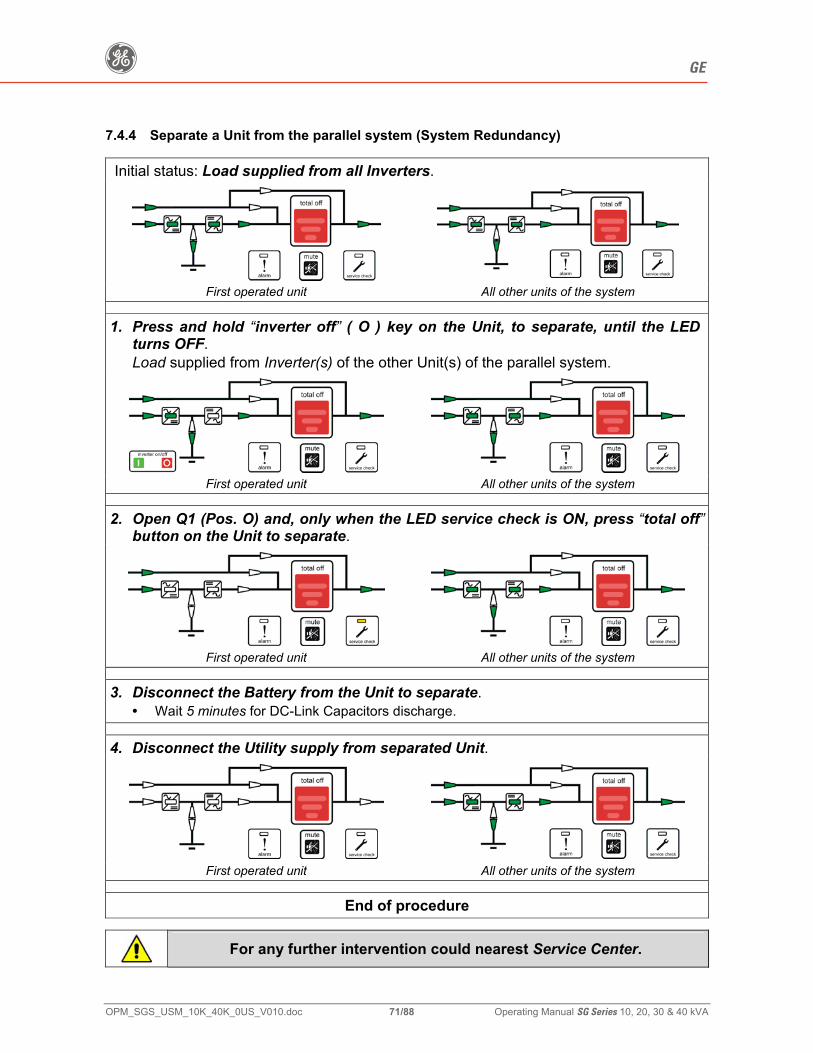
g GE
OPM_SGS_USM_10K_40K_0US_V010.doc 71/88 Operating Manual SG Series 10, 20, 30 & 40 kVA
7.4.4 Separate a Unit from the parallel system (System Redundancy)
Initial status: Load supplied from all Inverters.
First operated unit All other units of the system
1. Press and hold “inverter off” ( O ) key on the Unit, to separate, until the LED turns OFF. Load supplied from Inverter(s) of the other Unit(s) of the parallel system.
First operated unit All other units of the system
2. Open Q1 (Pos. O) and, only when the LED service check is ON, press “total off”button on the Unit to separate.
First operated unit All other units of the system
3. Disconnect the Battery from the Unit to separate. • Wait 5 minutes for DC-Link Capacitors discharge.
4. Disconnect the Utility supply from separated Unit.
First operated unit All other units of the system
End of procedure
For any further intervention could nearest Service Center.
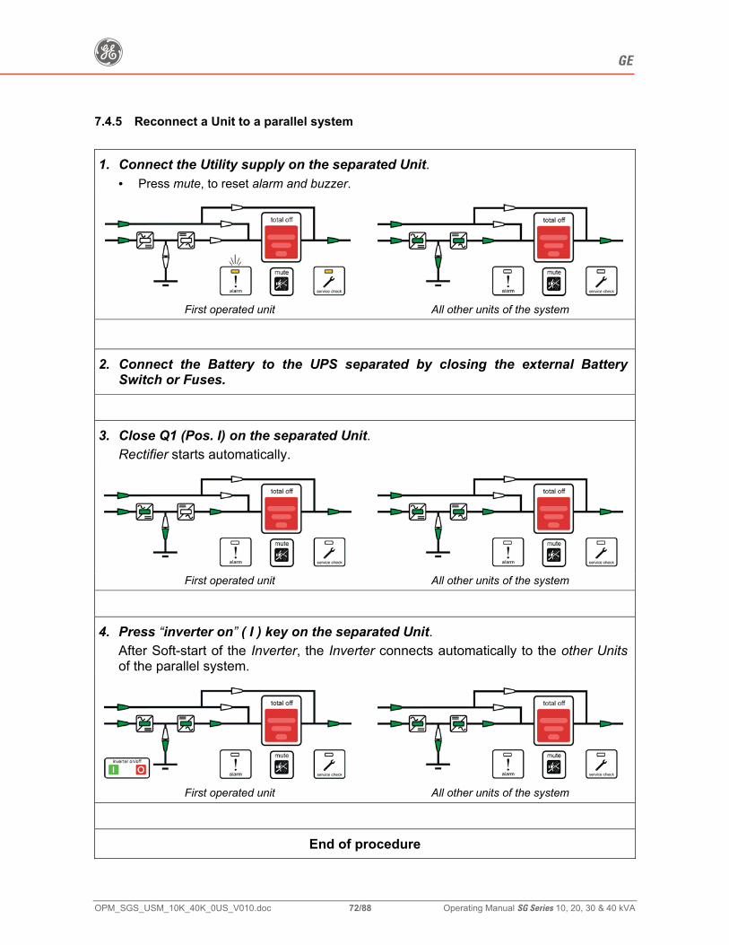
g GE
OPM_SGS_USM_10K_40K_0US_V010.doc 72/88 Operating Manual SG Series 10, 20, 30 & 40 kVA
7.4.5 Reconnect a Unit to a parallel system
1. Connect the Utility supply on the separated Unit. • Press mute, to reset alarm and buzzer.
First operated unit All other units of the system
2. Connect the Battery to the UPS separated by closing the external Battery
Switch or Fuses.
3. Close Q1 (Pos. I) on the separated Unit. Rectifier starts automatically.
First operated unit All other units of the system
4. Press “inverter on” ( I ) key on the separated Unit.
After Soft-start of the Inverter, the Inverter connects automatically to the other Units of the parallel system.
First operated unit All other units of the system
End of procedure
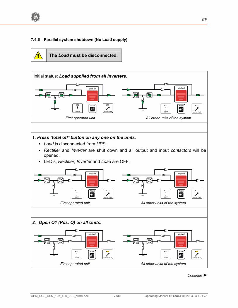
g GE
OPM_SGS_USM_10K_40K_0US_V010.doc 73/88 Operating Manual SG Series 10, 20, 30 & 40 kVA
7.4.6 Parallel system shutdown (No Load supply)
The Load must be disconnected.
Initial status: Load supplied from all Inverters.
First operated unit All other units of the system
1. Press “total off” button on any one on the units.
• Load is disconnected from UPS. • Rectifier and Inverter are shut down and all output and input contactors will be
opened. • LED’s, Rectifier, Inverter and Load are OFF.
First operated unit All other units of the system
2. Open Q1 (Pos. O) on all Units.
First operated unit All other units of the system
Continue ►
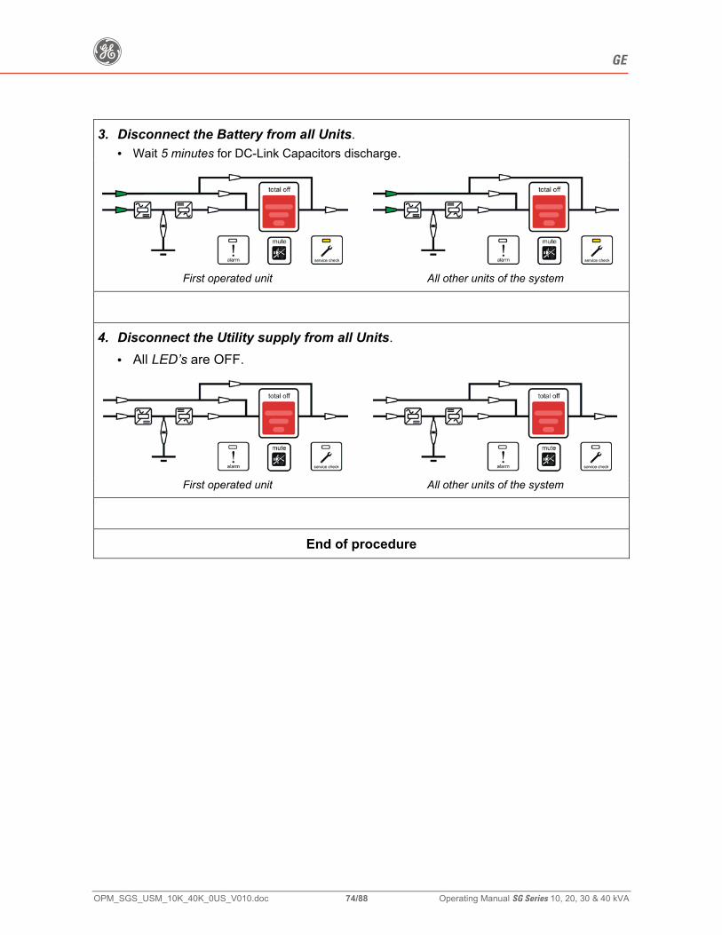
g GE
OPM_SGS_USM_10K_40K_0US_V010.doc 74/88 Operating Manual SG Series 10, 20, 30 & 40 kVA
3. Disconnect the Battery from all Units. • Wait 5 minutes for DC-Link Capacitors discharge.
First operated unit All other units of the system
4. Disconnect the Utility supply from all Units.
• All LED’s are OFF.
First operated unit All other units of the system
End of procedure
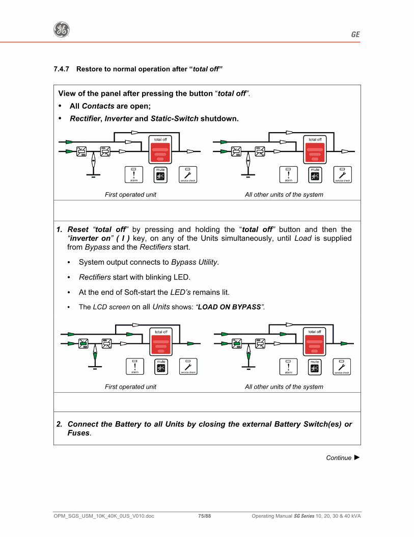
g GE
OPM_SGS_USM_10K_40K_0US_V010.doc 75/88 Operating Manual SG Series 10, 20, 30 & 40 kVA
7.4.7 Restore to normal operation after “total off”
View of the panel after pressing the button “total off”. • All Contacts are open; • Rectifier, Inverter and Static-Switch shutdown.
First operated unit All other units of the system
1. Reset “total off” by pressing and holding the “total off” button and then the
“inverter on” ( I ) key, on any of the Units simultaneously, until Load is supplied from Bypass and the Rectifiers start.
• System output connects to Bypass Utility.
• Rectifiers start with blinking LED.
• At the end of Soft-start the LED’s remains lit.
• The LCD screen on all Units shows: “LOAD ON BYPASS”.
First operated unit All other units of the system
2. Connect the Battery to all Units by closing the external Battery Switch(es) or
Fuses.
Continue ►
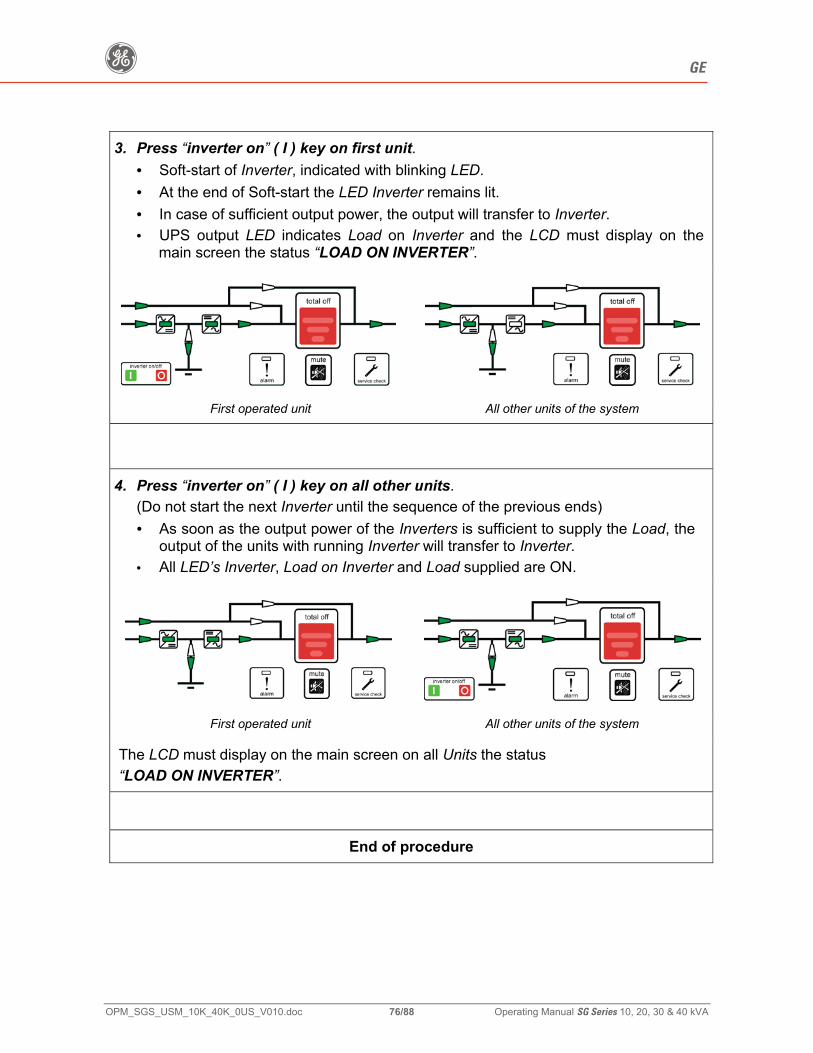
g GE
OPM_SGS_USM_10K_40K_0US_V010.doc 76/88 Operating Manual SG Series 10, 20, 30 & 40 kVA
3. Press “inverter on” ( I ) key on first unit. • Soft-start of Inverter, indicated with blinking LED. • At the end of Soft-start the LED Inverter remains lit. • In case of sufficient output power, the output will transfer to Inverter. • UPS output LED indicates Load on Inverter and the LCD must display on the
main screen the status “LOAD ON INVERTER”.
First operated unit All other units of the system
4. Press “inverter on” ( I ) key on all other units.
(Do not start the next Inverter until the sequence of the previous ends) • As soon as the output power of the Inverters is sufficient to supply the Load, the
output of the units with running Inverter will transfer to Inverter. • All LED’s Inverter, Load on Inverter and Load supplied are ON.
First operated unit All other units of the system
The LCD must display on the main screen on all Units the status “LOAD ON INVERTER”.
End of procedure
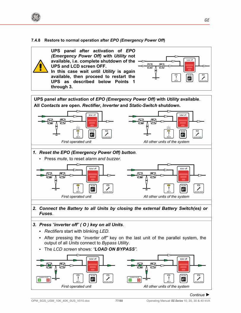
g GE
OPM_SGS_USM_10K_40K_0US_V010.doc 77/88 Operating Manual SG Series 10, 20, 30 & 40 kVA
7.4.8 Restore to normal operation after EPO (Emergency Power Off)
UPS panel after activation of EPO(Emergency Power Off) with Utility not available, i.e. complete shutdown of the UPS and LCD screen OFF. In this case wait until Utility is again available, then proceed to restart the UPS as described below Points 1 through 3.
UPS panel after activation of EPO (Emergency Power Off) with Utility available. All Contacts are open. Rectifier, Inverter and Static-Switch shutdown.
First operated unit All other units of the system
1. Reset the EPO (Emergency Power Off) button. • Press mute, to reset alarm and buzzer.
First operated unit All other units of the system
2. Connect the Battery to all Units by closing the external Battery Switch(es) or Fuses.
3. Press “inverter off” ( O ) key on all Units. • Rectifiers start with blinking LED. • After pressing the “inverter off” key on the last unit of the parallel system, the
output of all Units connect to Bypass Utility. • The LCD screen shows: “LOAD ON BYPASS”.
First operated unit All other units of the system
Continue ►
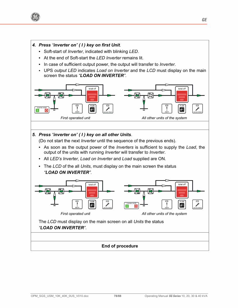
g GE
OPM_SGS_USM_10K_40K_0US_V010.doc 78/88 Operating Manual SG Series 10, 20, 30 & 40 kVA
4. Press “inverter on” ( I ) key on first Unit.
• Soft-start of Inverter, indicated with blinking LED. • At the end of Soft-start the LED Inverter remains lit. • In case of sufficient output power, the output will transfer to Inverter. • UPS output LED indicates Load on Inverter and the LCD must display on the main
screen the status “LOAD ON INVERTER”.
First operated unit All other units of the system
5. Press “inverter on” ( I ) key on all other Units.
(Do not start the next Inverter until the sequence of the previous ends). • As soon as the output power of the Inverters is sufficient to supply the Load, the
output of the units with running Inverter will transfer to Inverter. • All LED’s Inverter, Load on Inverter and Load supplied are ON. • The LCD of the all Units, must display on the main screen the status
“LOAD ON INVERTER”.
First operated unit All other units of the system
The LCD must display on the main screen on all Units the status “LOAD ON INVERTER”.
End of procedure
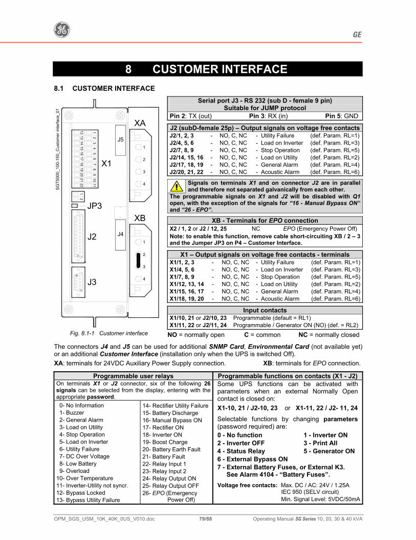
g GE
OPM_SGS_USM_10K_40K_0US_V010.doc 79/88 Operating Manual SG Series 10, 20, 30 & 40 kVA
8 CUSTOMER INTERFACE 8.1 CUSTOMER INTERFACE
Serial port J3 - RS 232 (sub D - female 9 pin) Suitable for JUMP protocol
Pin 2: TX (out) Pin 3: RX (in) Pin 5: GND
J2 (subD-female 25p) – Output signals on voltage free contactsJ2/1, 2, 3 - NO, C, NC - Utility Failure (def. Param. RL=1)J2/4, 5, 6 - NO, C, NC - Load on Inverter (def. Param. RL=3)J2/7, 8, 9 - NO, C, NC - Stop Operation (def. Param. RL=5)J2/14, 15, 16 - NO, C, NC - Load on Utility (def. Param. RL=2)J2/17, 18, 19 - NO, C, NC - General Alarm (def. Param. RL=4)J2/20, 21, 22 - NO, C, NC - Acoustic Alarm (def. Param. RL=6)
Signals on terminals X1 and on connector J2 are in parallel and therefore not separated galvanically from each other.
The programmable signals on X1 and J2 will be disabled with Q1 open, with the exception of the signals for “16 - Manual Bypass ON” and “26 - EPO”.
XB - Terminals for EPO connection X2 / 1, 2 or J2 / 12, 25 NC EPO (Emergency Power Off) Note: to enable this function, remove cable short-circuiting XB / 2 – 3 and the Jumper JP3 on P4 – Customer Interface.
X1 – Output signals on voltage free contacts - terminals X1/1, 2, 3 - NO, C, NC - Utility Failure (def. Param. RL=1)X1/4, 5, 6 - NO, C, NC - Load on Inverter (def. Param. RL=3)X1/7, 8, 9 - NO, C, NC - Stop Operation (def. Param. RL=5)X1/12, 13, 14 - NO, C, NC - Load on Utility (def. Param. RL=2)X1/15, 16, 17 - NO, C, NC - General Alarm (def. Param. RL=4)X1/18, 19, 20 - NO, C, NC - Acoustic Alarm (def. Param. RL=6)
Input contacts X1/10, 21 or J2/10, 23 Programmable (default = RL1) X1/11, 22 or J2/11, 24 Programmable / Generator ON (NO) (def. = RL2)
11213 2
14 3
15 4
16 5
17 6
18 7
19 8
20 9
21 10
22 11
114
91
X1
J2
J3
SGT5
000_
100-
150_
Cus
tom
er in
terfa
ce_0
1
J5
J4
XA
21
XB
1
2
3
4
1
2
3
4
JP3
Fig. 8.1-1 Customer interface NO = normally open C = common NC = normally closed
The connectors J4 and J5 can be used for additional SNMP Card, Environmental Card (not available yet)or an additional Customer Interface (installation only when the UPS is switched Off). XA: terminals for 24VDC Auxiliary Power Supply connection. XB: terminals for EPO connection.
Programmable user relays Programmable functions on contacts (X1 - J2) On terminals X1 or J2 connector, six of the following 26 signals can be selected from the display, entering with the appropriate password. 0- No Information 1- Buzzer 2- General Alarm 3- Load on Utility 4- Stop Operation 5- Load on Inverter 6- Utility Failure 7- DC Over Voltage 8- Low Battery 9- Overload 10- Over Temperature 11- Inverter-Utility not syncr. 12- Bypass Locked 13- Bypass Utility Failure
14- Rectifier Utility Failure 15- Battery Discharge 16- Manual Bypass ON 17- Rectifier ON 18- Inverter ON 19- Boost Charge 20- Battery Earth Fault 21- Battery Fault 22- Relay Input 1 23- Relay Input 2 24- Relay Output ON 25- Relay Output OFF 26- EPO (Emergency
Power Off)
Some UPS functions can be activated with parameters when an external Normally Open contact is closed on: X1-10, 21 / J2-10, 23 or X1-11, 22 / J2- 11, 24
Selectable functions by changing parameters (password required) are: 0 - No function 1 - Inverter ON 2 - Inverter OFF 3 - Print All 4 - Status Relay 5 - Generator ON 6 - External Bypass ON 7 - External Battery Fuses, or External K3.
See Alarm 4104 - “Battery Fuses”.
Voltage free contacts: Max. DC / AC: 24V / 1.25A IEC 950 (SELV circuit) Min. Signal Level: 5VDC/50mA
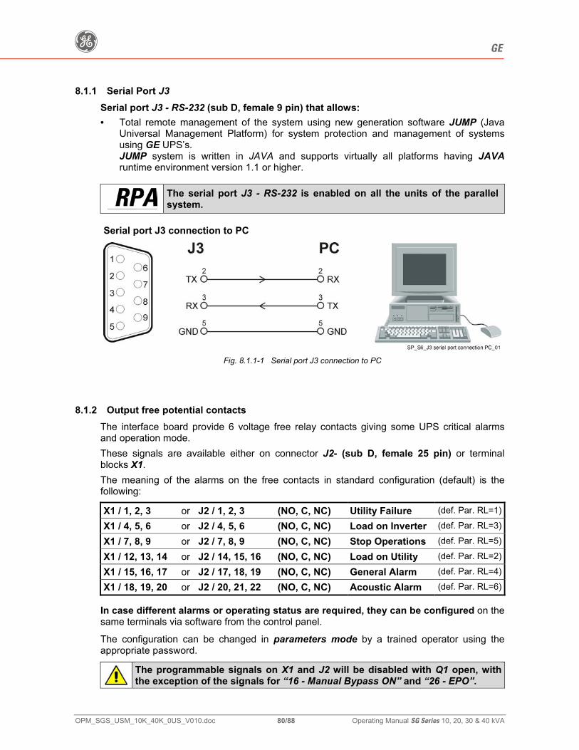
g GE
OPM_SGS_USM_10K_40K_0US_V010.doc 80/88 Operating Manual SG Series 10, 20, 30 & 40 kVA
8.1.1 Serial Port J3 Serial port J3 - RS-232 (sub D, female 9 pin) that allows: • Total remote management of the system using new generation software JUMP (Java
Universal Management Platform) for system protection and management of systems using GE UPS’s. JUMP system is written in JAVA and supports virtually all platforms having JAVA runtime environment version 1.1 or higher.
The serial port J3 - RS-232 is enabled on all the units of the parallel system.
Serial port J3 connection to PC
Fig. 8.1.1-1 Serial port J3 connection to PC
8.1.2 Output free potential contacts The interface board provide 6 voltage free relay contacts giving some UPS critical alarms and operation mode.
These signals are available either on connector J2- (sub D, female 25 pin) or terminal blocks X1.
The meaning of the alarms on the free contacts in standard configuration (default) is the following:
X1 / 1, 2, 3 or J2 / 1, 2, 3 (NO, C, NC) Utility Failure (def. Par. RL=1)
X1 / 4, 5, 6 or J2 / 4, 5, 6 (NO, C, NC) Load on Inverter (def. Par. RL=3)
X1 / 7, 8, 9 or J2 / 7, 8, 9 (NO, C, NC) Stop Operations (def. Par. RL=5)
X1 / 12, 13, 14 or J2 / 14, 15, 16 (NO, C, NC) Load on Utility (def. Par. RL=2)
X1 / 15, 16, 17 or J2 / 17, 18, 19 (NO, C, NC) General Alarm (def. Par. RL=4)
X1 / 18, 19, 20 or J2 / 20, 21, 22 (NO, C, NC) Acoustic Alarm (def. Par. RL=6)
In case different alarms or operating status are required, they can be configured on the same terminals via software from the control panel.
The configuration can be changed in parameters mode by a trained operator using the appropriate password.
The programmable signals on X1 and J2 will be disabled with Q1 open, with the exception of the signals for “16 - Manual Bypass ON” and “26 - EPO”.
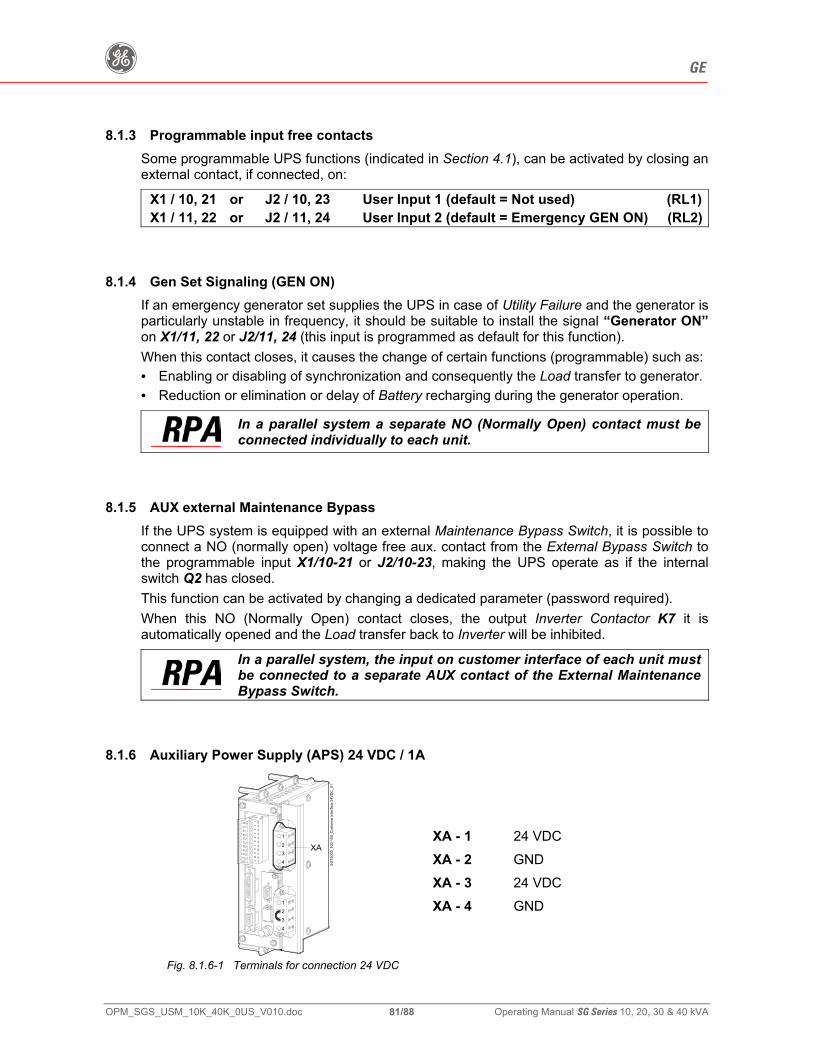
g GE
OPM_SGS_USM_10K_40K_0US_V010.doc 81/88 Operating Manual SG Series 10, 20, 30 & 40 kVA
8.1.3 Programmable input free contacts Some programmable UPS functions (indicated in Section 4.1), can be activated by closing an external contact, if connected, on:
X1 / 10, 21 or J2 / 10, 23 User Input 1 (default = Not used) (RL1)X1 / 11, 22 or J2 / 11, 24 User Input 2 (default = Emergency GEN ON) (RL2)
8.1.4 Gen Set Signaling (GEN ON) If an emergency generator set supplies the UPS in case of Utility Failure and the generator is particularly unstable in frequency, it should be suitable to install the signal “Generator ON” on X1/11, 22 or J2/11, 24 (this input is programmed as default for this function).
When this contact closes, it causes the change of certain functions (programmable) such as: • Enabling or disabling of synchronization and consequently the Load transfer to generator. • Reduction or elimination or delay of Battery recharging during the generator operation.
In a parallel system a separate NO (Normally Open) contact must be connected individually to each unit.
8.1.5 AUX external Maintenance Bypass If the UPS system is equipped with an external Maintenance Bypass Switch, it is possible to connect a NO (normally open) voltage free aux. contact from the External Bypass Switch to the programmable input X1/10-21 or J2/10-23, making the UPS operate as if the internal switch Q2 has closed.
This function can be activated by changing a dedicated parameter (password required).
When this NO (Normally Open) contact closes, the output Inverter Contactor K7 it is automatically opened and the Load transfer back to Inverter will be inhibited.
In a parallel system, the input on customer interface of each unit must be connected to a separate AUX contact of the External Maintenance Bypass Switch.
8.1.6 Auxiliary Power Supply (APS) 24 VDC / 1A
4
1
32
321
SGT5
000_
100-
150_
Cus
tom
er in
terfa
ce 2
4VD
C_0
1
4
XA
Fig. 8.1.6-1 Terminals for connection 24 VDC
XA - 1 24 VDC XA - 2 GND XA - 3 24 VDC XA - 4 GND
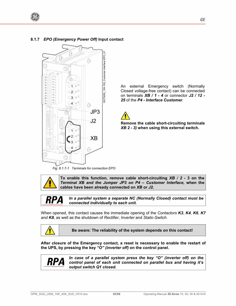
g GE
OPM_SGS_USM_10K_40K_0US_V010.doc 82/88 Operating Manual SG Series 10, 20, 30 & 40 kVA
8.1.7 EPO (Emergency Power Off) Input contact
4
1
32
321
SGT5
000_
100-
150_
Cus
tom
er in
terfa
ce E
PO_0
14
XB
J2JP3
Fig. 8.1.7-1 Terminals for connection EPO
An external Emergency switch (Normally Closed voltage-free contact) can be connected on terminals XB / 1 - 4 or connector J2 / 12 - 25 of the P4 - Interface Customer.
Remove the cable short-circuiting terminals XB 2 - 3) when using this external switch.
To enable this function, remove cable short-circuiting XB / 2 - 3 on the Terminal XB and the Jumper JP3 on P4 – Customer Interface, when the cables have been already connected on XB or J2.
In a parallel system a separate NC (Normally Closed) contact must be connected individually to each unit.
When opened, this contact causes the immediate opening of the Contactors K3, K4, K6, K7 and K8, as well as the shutdown of Rectifier, Inverter and Static-Switch.
Be aware: The reliability of the system depends on this contact!
After closure of the Emergency contact, a reset is necessary to enable the restart of the UPS, by pressing the key “O” (inverter off) on the control panel.
In case of a parallel system press the key “O” (inverter off) on the control panel of each unit connected on parallel bus and having it’s output switch Q1 closed.
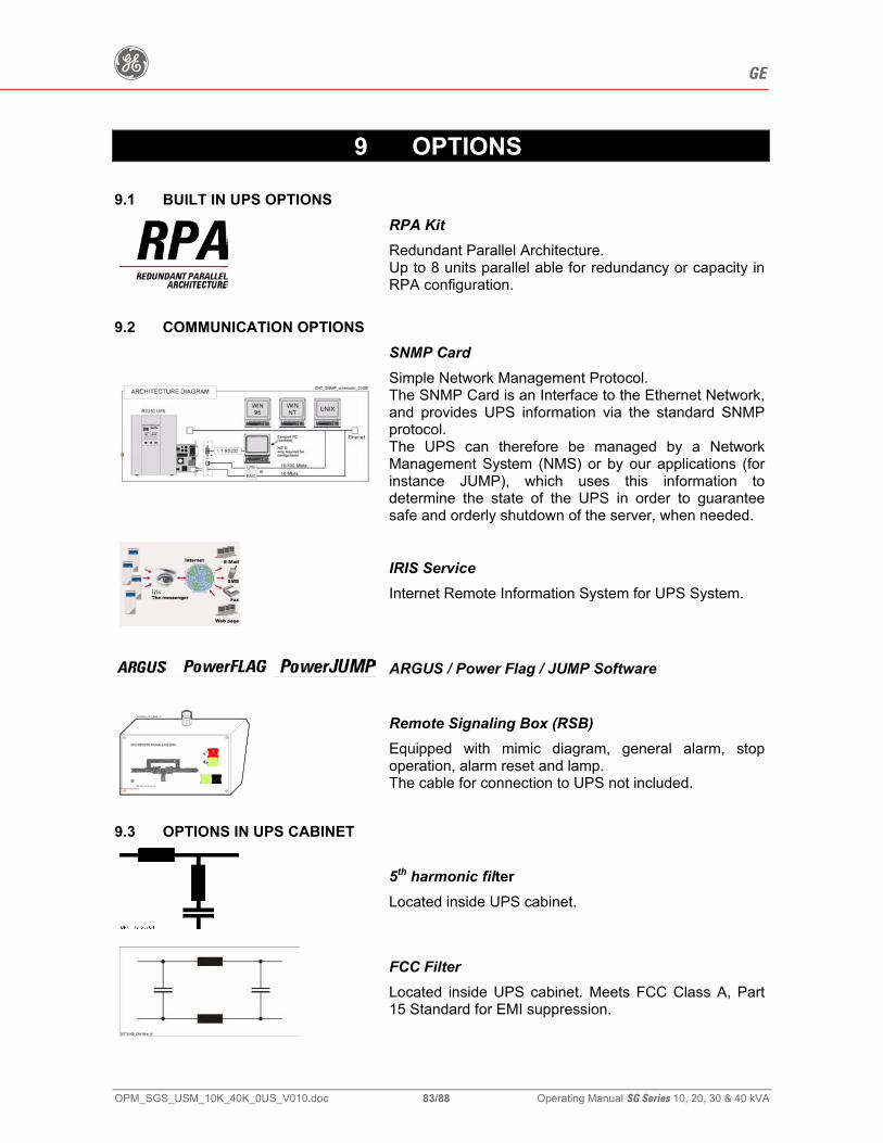
g GE
OPM_SGS_USM_10K_40K_0US_V010.doc 83/88 Operating Manual SG Series 10, 20, 30 & 40 kVA
9 OPTIONS
9.1 BUILT IN UPS OPTIONS
RPA Kit Redundant Parallel Architecture. Up to 8 units parallel able for redundancy or capacity in RPA configuration.
9.2 COMMUNICATION OPTIONS
SNMP Card Simple Network Management Protocol. The SNMP Card is an Interface to the Ethernet Network, and provides UPS information via the standard SNMP protocol. The UPS can therefore be managed by a Network Management System (NMS) or by our applications (for instance JUMP), which uses this information to determine the state of the UPS in order to guarantee safe and orderly shutdown of the server, when needed.
IRIS Service Internet Remote Information System for UPS System.
ARGUS / Power Flag / JUMP Software
Mute Test
SGT5000_OPT_RMS_01
Stop
Alarm
gGE Digital Energy
Remote Signaling Box (RSB) Equipped with mimic diagram, general alarm, stop operation, alarm reset and lamp. The cable for connection to UPS not included.
9.3 OPTIONS IN UPS CABINET
5th harmonic filter Located inside UPS cabinet.
FCC Filter Located inside UPS cabinet. Meets FCC Class A, Part 15 Standard for EMI suppression.
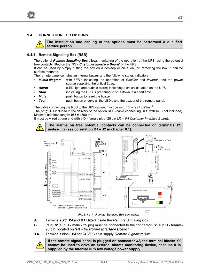
g GE
OPM_SGS_USM_10K_40K_0US_V010.doc 84/88 Operating Manual SG Series 10, 20, 30 & 40 kVA
9.4 CONNECTION FOR OPTIONS
The installation and cabling of the options must be performed a qualified service person.
9.4.1 Remote Signaling Box (RSB) The optional Remote Signaling Box allows monitoring of the operation of the UPS, using the potential free contacts fitted on the “P4 - Customer Interface Board“ of the UPS. It can be used by simply putting the box on a desktop or on a wall or, removing the box, it can be surface mounted. The remote panel contains an internal buzzer and the following status indicators: • Mimic diagram with LED's indicating the operation of Rectifier and Inverter, and the power
source supplying the critical Load. • Alarm (LED light and audible alarm) indicating a critical situation on the UPS. • Stop indicating the UPS is preparing to shut down in a short time. • Mute push button to reset the buzzer. • Test push button checks all the LED’s and the buzzer of the remote panel. The cable connecting the RSB to the UPS cabinet must be min. 16 wires / 0.25mm2. The plug B is included in the delivery of the option RSB (cable connecting UPS with RSB not included). Maximal admitted length: 985 ft (300 m). It must be wired at one end with a D - female plug- 25 pin (J2 – P4 Customer Interface Board).
The alarms on free potential contacts can be connected on terminals X1 instead J2 (see correlation X1 – J2 in chapter 8.1).
Mute Test
max
985
ft / 3
00m
yellow/brownwhite/yellow
12
43
5 brown/green
76
8
109
11
white/green
blue/red
violet
grey/pink
1312
14
1615
17 yellowgreen
brown20
2223
1918
21 white
24
16COMMON ALLARM
AUX. BUZZER
STOP OPERATION
202223
1719
38
LOAD ON MAINS
LOAD ON INVERTER
565550
4344
49
4042
SIGNALLING
UTILITY FAILURE
GND24V
34
37
333231
X15IM6544
12
J2 -
SUB
D -
MAL
E
REMOTE
X3
X4A
A
B -
P4 - IM0005
B PLUGJ2
77mm3 i
n
130m
m
216mm
5 1/
4" in
8 1/2" in
25
black
P.S.: The above mentioned colors are
XATERMINALS BLOCK
TERMINALSXA
pink
red
blue
grey
pinkredgreyblue
SUB D - MALE
suitables only for XY standard cable
SGT5
000_
OPT
_010
-150
_RM
S_01
US
11213 2
14 3
15 4
16 5
17 6
18 7
19 8
20 9
21 10
22 11
114
91
21
1
2
3
4
1
2
3
4
J2
XA
BLOCK BOX
Pink + Red
Grey + Blue
Stop
Alarm
gGE Digital Energy
Customer Interface
2
1
Fig. 8.4.1-1 Remote Signaling Box connection
A Terminals X3, X4 and X15 fitted inside the Remote Signaling Box.
B Plug J2 (sub D - male - 25 pin) must be connected to the connector J2 (sub D - female-25 pin) located on “P4 - Customer Interface Board“.
XA Terminals block XA for 24 VDC / 1A supply Remote Signaling Box.
If the remote signal panel is plugged on connector J2, the terminal blocks X1 cannot be used to drive an external alarms monitoring device, because it is supplied by the internal UPS low voltage power supply.
g GE
OPM_SGS_USM_10K_40K_0US_V010.doc 85/88 Operating Manual SG Series 10, 20, 30 & 40 kVA
10 MAINTENANCE 10.1 MAINTENANCE A UPS system, like other electrical equipment, needs periodic preventive maintenance.
A regular maintenance check of your installation guarantees higher reliability of your safe critical power supply.
Preventive maintenance work on the UPS can be done only by trained Service technicians.
We therefore recommend you sign a Maintenance and Service contract with GE Global Services @ 1-800-637-1738 10.1.1 Service check
If this lamp lights up during the normal operation, that means that the unit has not been serviced for the last 20,000 hours by a GE trained technician.
We highly recommend that you contact your Service Center for preventive maintenance work. 10.1.2 Fans and ventilation
We recommend a periodic cleaning of the ventilation channels and grids on the UPS system, in order to guarantee proper air circulation in the unit and in the Battery.
We recommend replacement of the fans in the units every 20,000 hours. 10.1.3 Other components with limited lifetime
We recommend the replacement of components such as Filter Capacitors and Lithium Battery for the backup of data on the control boards of the units every 50,000 hours. 10.1.4 Battery
We recommend a periodic Manual Battery Test, especially if the Automatic Battery Test is disabled, in order to verify if the Battery can provide the expected backup time in case of Utility Failure.
We recommend this test be performed at least every 3 months, especially if the Battery is not sufficiently discharged during normal operation. The discharge time you use should be at least half of the Battery runtime.
For Automatic Battery Test setting, a special code is required to enter user set-up parameters. The start up technician has access to this code and can program this feature during start up.
Please consider that, if you did a full Battery Test to verify the full runtime of the Battery, the charger needs at least 8 hours to recharge the Battery up to 90% of its capacity.
g GE
OPM_SGS_USM_10K_40K_0US_V010.doc 86/88 Operating Manual SG Series 10, 20, 30 & 40 kVA
10.1.5 Long shut-down periods of the UPS-system To guarantee that the Battery is fully charged, the UPS system should be in operation for at least 12 hours every 3 months.
If not the Battery may be permanently damaged. 10.1.6 UPS room conditions and temperature The UPS room and the Battery Room have to be maintained clean and free from dust. A high temperature of the UPS room and of the Battery Room affect the lifetime of several components inside the equipment. The Battery is very sensitive to room temperatures above 77°F (25°C). 10.1.7 Long shut-down periods of the UPS-system a) Cleaning, a visual inspection and a mechanical inspection of the UPS modules. b) Replacement of defective parts or the preventive replacement of parts with a defined lifetime c) “Updating” of the equipment (technical improvements subsequent to the delivery). d) Check the calibration of DC voltage and Inverter Output Voltage and Frequency. e) Check of the settings of the electronic regulation, the control and the alarm circuits of the
Rectifier(s) and Inverter(s). f) Functional checks on Thyristors, Diodes, Transformers, Filter Components, e.g. to ensure that
they are operating within the specified design parameters. g) Overall performance test including a Utility Failure simulation with and without the Load. h) Monitoring Battery operation in discharge and recharge mode including any boost charge
duties.
g GE
OPM_SGS_USM_10K_40K_0US_V010.doc 87/88 Operating Manual SG Series 10, 20, 30 & 40 kVA
11 NOTES
11.1 NOTES FORM It is recommended to note in this section Notes, with date and short description all the operations performed on the UPS, as: maintenance, components replacement, abnormal situations, etc.
Date Description Done by
g GE
OPM_SGS_USM_10K_40K_0US_V010.doc 88/88 Operating Manual SG Series 10, 20, 30 & 40 kVA
RIDER FOR WARRANTY FOR SALE OF SiteProTM, DIGITAL ENERGYTM SG Series and LP
Series UPS. This Rider incorporates by reference the Terms and Conditions in GE Industrial Systems (herein called GE) GETC2003, and includes the following additional provisions contained herein. In the event of conflict between this Rider and GETC2003, the Rider shall take precedence. Limitation on use with life support equipment: Customer understands and agrees that the products sold hereunder are not intended for application or use, and shall not be used: (i) in conjunction with or for life support equipment when failure of any product can be reasonably be expected to cause failure of or diminish the effectiveness of such life support Customer represents and warrants that it shall NOT USE THE PRODUCTS FOR ANY SUCH PURPOSES, OR PERMIT OTHERS TO USE THE PRODUCTS FOR ANY SUCH PURPOSES. If, in breach of the foregoing, any such use occurs, Seller shall have no liability for any resulting damage or injury, in addition to any other legal or equitable rights of Seller, Customer shall indemnify Seller against any such liability, whether arising as a result of breach of contract, warranty, indemnity, tort (including negligence), strict liability or otherwise. WARRANTY: Seller warrants to Customer that during the “Warranty Period” applicable for its SitePro, Digital EnergyTM SG Series and LP Series UPS Product furnished hereunder (the “Product”) will be free from defects in material, workmanship and title. The warranty period (“Warranty Period”) for the specified Product begins on the earlier of three (3) months after the delivery date or upon commissioning of the Product (if applicable) and ends at the end of the period as set forth below: The Warranty Period for the specified Product is as follows: SitePro / Digital EnergyTM SG Series UPS 12 Months LP Series UPS 24 Months In no case does this warranty apply to any failure or nonconformance with specifications caused by or attributable to any associated or complementary products not supplied under these Terms and Conditions, nor shall it in any case apply to the quantity or quality of the product of Customer or the process of manufacture on which any products are used. The warranties and remedies set forth herein are conditioned upon (a) proper transportation, handling, storage, installation, commissioning, operation, use and maintenance in conformance with the operation instruction manuals (including revisions thereto) provided by Seller, any applicable recommendations of Seller and any applicable laws, regulations or codes (b) repair or modification pursuant to Seller’s instructions or approval and (c) Customer promptly notifying Seller of any defects and, if required, promptly making the Product available for correction at Customer’s expense. This warranty shall not apply (a) if Customer or any other unauthorized person has made any modifications, alterations or repairs to the Product not authorized by Seller, including Customer’s use of parts in conjunction with the Product (excluding batteries) not admitted or delivered by Seller, (b) to a Product with removed or altered serial numbers, (c) to a Product damaged by acts of God, sources external to the Product, misuse, accident, abuse, neglect, negligence, or use beyond rated capacity, and (d) if GE authorized field service technician does not commission Digital Energyæ SG Series UPS and SitePro UPS." If any Product or service fails to meet the foregoing warranties (except title), Seller shall thereupon correct any such failure either, at its option, by (i) repairing any defective or damaged part or Product and/or reperforming any defective service or (ii) making available, F.O.B. at Seller’s facility, place of manufacture or other mutually agreed upon point of shipment, any necessary repaired or replacement parts; provided, however, that prior to repairing any defective or damaged part or Product, Seller shall have received, at Customer’s cost, such part or Product in need of repair or replacement.
If reperformance is not practicable, Seller will furnish without charge services in an amount essentially equal to those that, in the sole judgment of Seller, would have been required for reperformance. Where a failure cannot be corrected by Seller’s reasonable efforts, the parties will negotiate an equitable adjustment in price. In providing a replacement Product or parts, Seller reserves the right to use refurbished circuit boards, which shall be warranted in accordance with this Warranty Provision. The correction of any failure or the supply of repaired or replacement parts or Products pursuant to this Warranty Provision shall not extend the duration of the applicable Warranty Period. Seller does not warrant the following items: (i) computer hardware, (ii) any computer software, including software provided by Seller with any Product, (iii) products or services obtained from others or (iv) any batteries used in conjunction with the products, including those provided by Seller, and in regard to these items, only the warranty of the manufacturer, if any, shall apply. Seller's obligation under this Provision entitled “Warranty” shall terminate immediately upon any modification of the Product by Customer unless made with the approval of Seller. The Warranty Period applicable to each Product can be extended, if Customer purchases an extended warranty from Seller. If Customer purchases an extended warranty from Seller, the terms of such extended warranty shall supersede these warranty provisions. THE PRECEDING PARAGRAPHS OF THIS WARRANTY PROVISION SET FORTH THE EXCLUSIVE CLAIMS (EXCEPT AS TO TITLE) BASED ON DEFECT IN OR FAILURE OF A PRODUCT, WHETHER THE CLAIM IS IN CONTRACT, INDEMNITY, WARRANTY, TORT (INCLUDING NEGLIGENCE), STRICT LIABILITY OR OTHERWISE. Upon the expiration of the applicable Warranty Period, all such liability shall terminate and Customer shall have a reasonable time, not to exceed thirty (30) days after the applicable Warranty Period, to give written notice of any defects that appeared during the Warranty Period. THE FOREGOING WARRANTIES ARE EXCLUSIVE AND IN AND IN LIEU OF ALL OTHER WARRANTIES, WHETHER WRITTEN, ORAL, IMPLIED OR STATUTORY. NO IMPLIED STATUTORY WARRANTY OF MERCHANTABILITY OR FITNESS FOR A PARTICULAR PURPOSE SHALL APPLY. INSTALLATION AND COMMISSIONING OF INSTALLABLE SYSTEMS: If the Products cannot be installed immediately after delivery, Customer is responsible for maintaining proper storage conditions according to operating manuals and any other instructions provided by Seller. Installable Products may only be installed by certified electrical installers and must be installed according to Seller’s specifications, appropriate national electrical codes and accepted standards of workmanship. For purposes of these GE Terms and Conditions, “installable Products” shall mean Products that require the services of a certified electrical installer to be connected to the power grid. The commissioning of installable Products may only be done by a technician authorized by Seller and must be done according to Seller’s specifications. For purposes of these GE Terms and Conditions, “commissioning” shall mean the start-up of the installable Products and the testing of the installable Products in connection with the load. If commissioning is to be performed by Seller, Seller may refuse to commission the installable Products, if the operating conditions at Customer’s site do not allow safe commissioning and operation of the installable Products. Any costs resulting from a delay in commissioning will be charged to Customer.