Embed Size (px)
Citation preview
CB1N3922en 30.03.2009 Building Technologies
s 3922
ClimatixTM Climatix extension
module 15 I/Os POL965.00/XXX
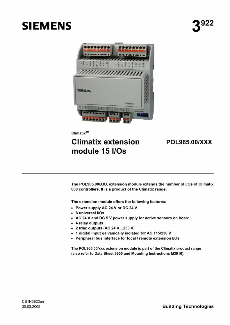
The POL965.00/XXX extension module extends the number of I/Os of Climatix 600 controllers. It is a product of the Climatix range. The extension module offers the following features: • Power supply AC 24 V or DC 24 V • 8 universal I/Os • AC 24 V and DC 5 V power supply for active sensors on board • 4 relay outputs • 2 triac outputs (AC 24 V…230 V) • 1 digital input galvanically isolated for AC 115/230 V • Peripheral bus interface for local / remote extension I/Os The POL965.00/xxx extension module is part of the Climatix product range (also refer to Data Sheet 3900 and Mounting Instructions M3910).
2 / 12
Siemens Climatix extension module 15 I/Os CB1N3922en Building Technologies 30.03.2009
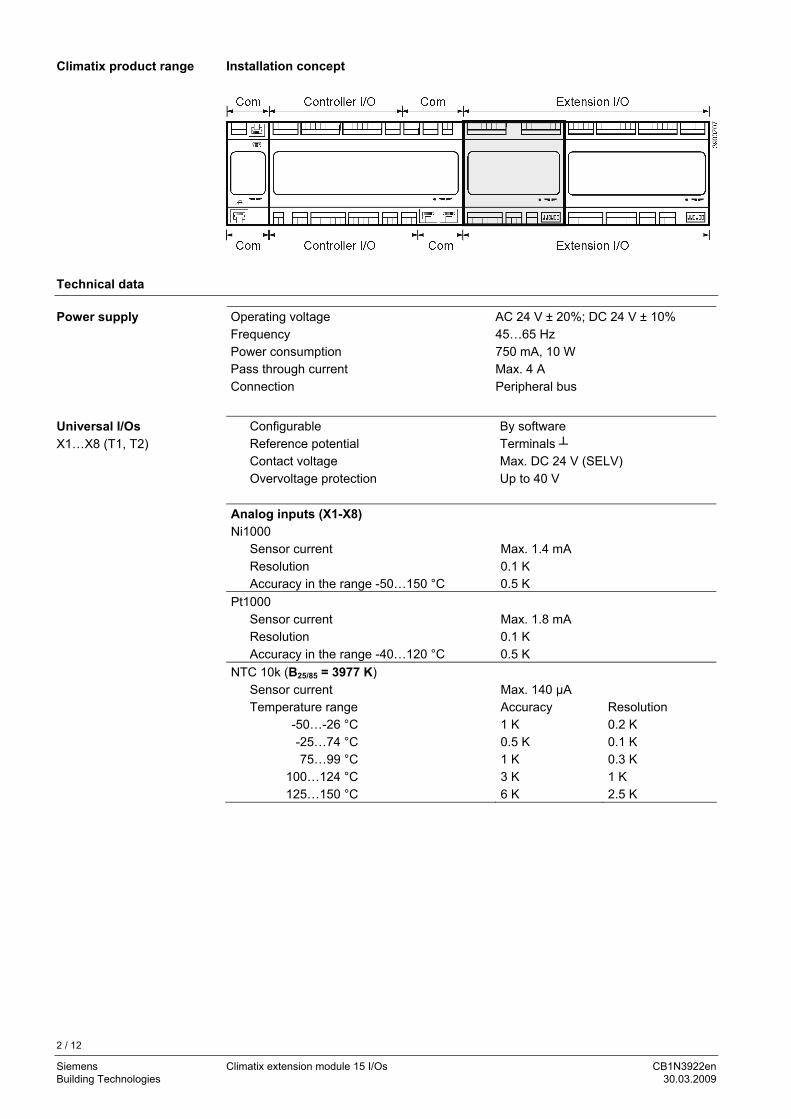
Installation concept
Technical data
Operating voltage AC 24 V ± 20%; DC 24 V ± 10% Frequency 45…65 Hz Power consumption 750 mA, 10 W Pass through current Max. 4 A Connection Peripheral bus
Configurable Reference potential
By software Terminals
Contact voltage Max. DC 24 V (SELV) Overvoltage protection Up to 40 V
Analog inputs (X1-X8) Ni1000
Sensor current Max. 1.4 mA Resolution 0.1 K Accuracy in the range -50…150 °C 0.5 K
Pt1000 Sensor current Max. 1.8 mA Resolution 0.1 K Accuracy in the range -40…120 °C 0.5 K
NTC 10k (B25/85 = 3977 K) Sensor current Max. 140 μA Temperature range Accuracy Resolution
-50…-26 °C 1 K 0.2 K -25…74 °C 0.5 K 0.1 K 75…99 °C 1 K 0.3 K
100…124 °C 3 K 1 K 125…150 °C 6 K 2.5 K
Climatix product range
Power supply
Universal I/Os X1…X8 (T1, T2)
3 / 12
Siemens Climatix extension module 15 I/Os CB1N3922en Building Technologies 30.03.2009
NTC 100k (B25/85 = 3977 K) Sensor current Max. 140 μA Temperature range Accuracy Resolution
-25…-11 °C 3 K 0.2 K -10…9 °C 1 K 0.1 K 10…99 °C 0.5 K 0.1 K
100...150 °C 1 K 0.2 K 0...2.5 kΩ
Sensor current Max. 1.8 mA Resolution 1 Ω Accuracy 4 Ω
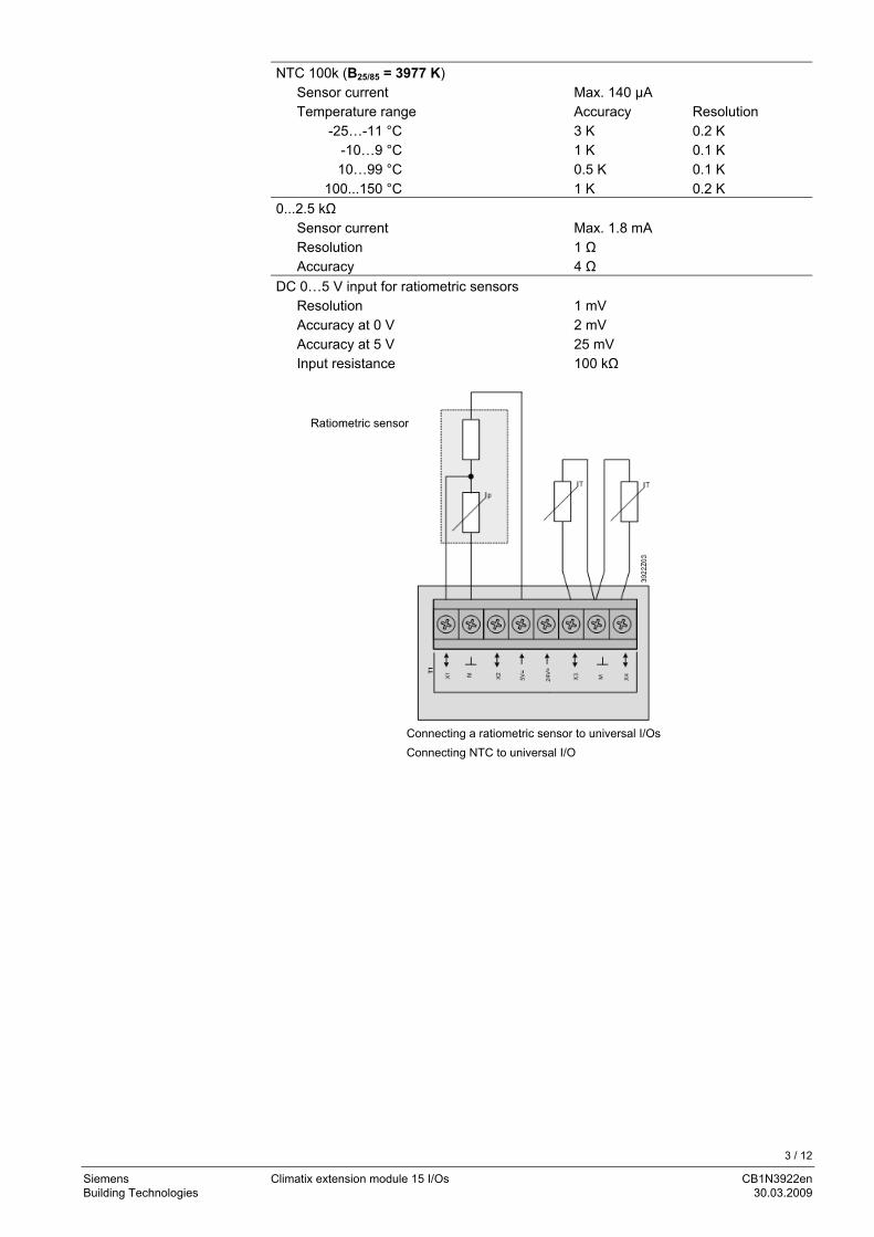
DC 0…5 V input for ratiometric sensors Resolution 1 mV Accuracy at 0 V 2 mV Accuracy at 5 V 25 mV Input resistance 100 kΩ
Ratiometric sensor
Connecting a ratiometric sensor to universal I/Os Connecting NTC to universal I/O
4 / 12
Siemens Climatix extension module 15 I/Os CB1N3922en Building Technologies 30.03.2009
Analog inputs (X1…X8) DC 0...10 V input
Resolution 1 mV Accuracy at 0 V 2 mV Accuracy at 5 V 25 mV Accuracy at 10 V 50 mV Input resistance 100 kΩ
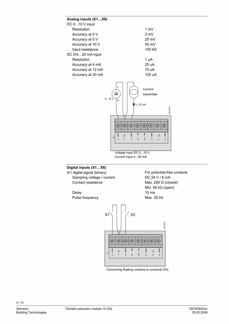
DC 0/4…20 mA input Resolution 1 μA Accuracy at 4 mA 25 uA Accuracy at 12 mA 70 uA Accuracy at 20 mA 120 uA
Voltage input DC 0...10 V Current input 4...20 mA
Digital inputs (X1…X8) 0/1 digital signal (binary) For potential-free contacts
Sampling voltage / current DC 24 V / 8 mA Contact resistance Max. 200 Ω (closed)
Min. 50 kΩ (open) Delay 10 ms Pulse frequency Max. 30 Hz
Connecting floating contacts to universal I/Os
Current transmitter
5 / 12
Siemens Climatix extension module 15 I/Os CB1N3922en Building Technologies 30.03.2009
Analog output (X1-X4) DC 0…10 V output
Resolution 11 mV Accuracy at 0 V 66 mV Accuracy at 5 V 95 mV Accuracy at 10 V 124 mV Output current 1 mA (short-circuit-proof)
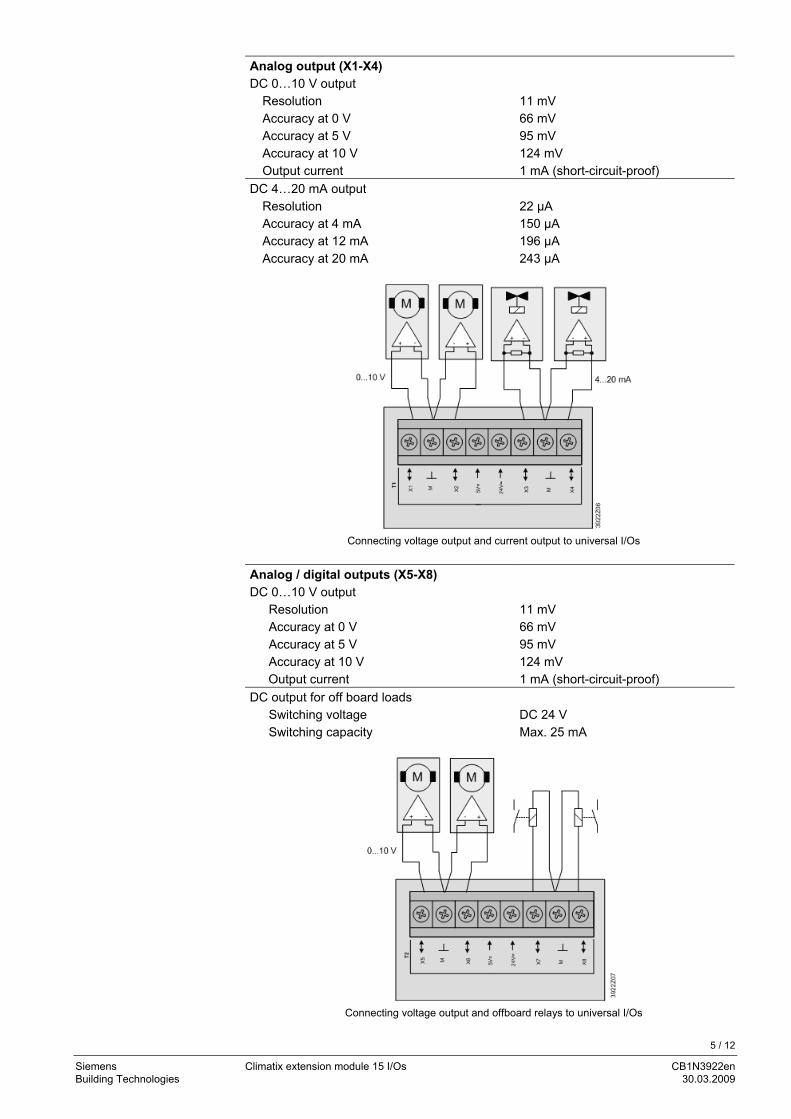
DC 4…20 mA output Resolution 22 μA Accuracy at 4 mA 150 μA Accuracy at 12 mA 196 μA Accuracy at 20 mA 243 μA
Connecting voltage output and current output to universal I/Os
Analog / digital outputs (X5-X8) DC 0…10 V output
Resolution 11 mV Accuracy at 0 V 66 mV Accuracy at 5 V 95 mV Accuracy at 10 V 124 mV Output current 1 mA (short-circuit-proof)
DC output for off board loads Switching voltage DC 24 V Switching capacity Max. 25 mA
Connecting voltage output and offboard relays to universal I/Os
6 / 12
Siemens Climatix extension module 15 I/Os CB1N3922en Building Technologies 30.03.2009
2 x 2 outputs
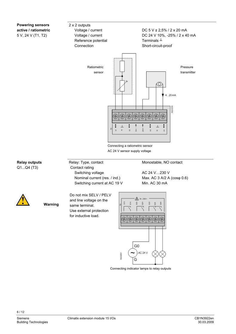
Voltage / current DC 5 V ± 2,5% / 2 x 20 mA Voltage / current DC 24 V 10%, -25% / 2 x 40 mA Reference potential Terminals Connection Short-circuit-proof
Ratiometric
sensor
Pressure transmitter
Connecting a ratiometric sensor AC 24 V sensor supply voltage
Relay: Type, contact Monostable, NO contact Contact rating
Switching voltage AC 24 V…230 V Nominal current (res. / ind.) Max. AC 3 A/2 A (cosφ 0.6) Switching current at AC 19 V Min. AC 30 mA
Do not mix SELV / PELV and line voltage on the same terminal. Use external protection for inductive load.
Connecting indicator lamps to relay outputs
Powering sensors active / ratiometric 5 V, 24 V (T1, T2)
Relay outputs Q1...Q4 (T3)
Warning
7 / 12
Siemens Climatix extension module 15 I/Os CB1N3922en Building Technologies 30.03.2009
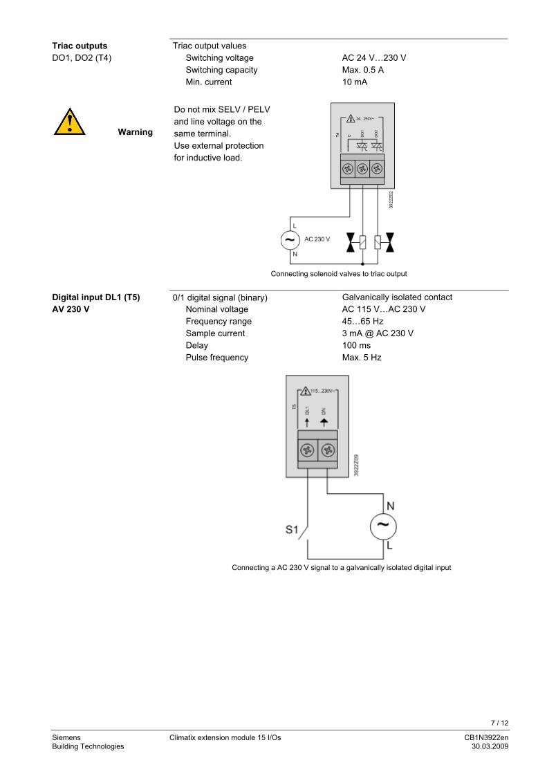
Triac output values Switching voltage AC 24 V…230 V Switching capacity Max. 0.5 A Min. current 10 mA
Do not mix SELV / PELV and line voltage on the same terminal. Use external protection for inductive load.
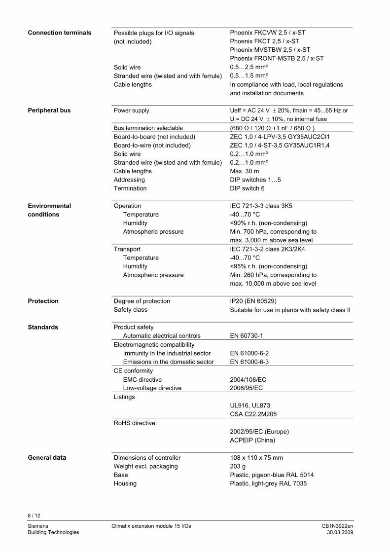
Connecting solenoid valves to triac output 0/1 digital signal (binary) Galvanically isolated contact
Nominal voltage AC 115 V…AC 230 V Frequency range 45…65 Hz Sample current 3 mA @ AC 230 V Delay 100 ms Pulse frequency Max. 5 Hz
Connecting a AC 230 V signal to a galvanically isolated digital input
Triac outputs DO1, DO2 (T4)
Warning
Digital input DL1 (T5) AV 230 V
8 / 12
Siemens Climatix extension module 15 I/Os CB1N3922en Building Technologies 30.03.2009
Possible plugs for I/O signals (not included)
Phoenix FKCVW 2,5 / x-ST Phoenix FKCT 2,5 / x-ST Phoenix MVSTBW 2,5 / x-ST Phoenix FRONT-MSTB 2,5 / x-ST
Solid wire 0.5…2.5 mm² Stranded wire (twisted and with ferrule) 0.5…1.5 mm² Cable lengths In compliance with load, local regulations
and installation documents Power supply Ueff = AC 24 V ± 20%, fmain = 45...65 Hz or
U = DC 24 V ± 10%, no internal fuse Bus termination selectable (680 Ω / 120 Ω +1 nF / 680 Ω ) Board-to-board (not included) Board-to-wire (not included)
ZEC 1,0 / 4-LPV-3,5 GY35AUC2CI1 ZEC 1,0 / 4-ST-3,5 GY35AUC1R1,4
Solid wire 0.2…1.0 mm² Stranded wire (twisted and with ferrule) 0.2…1.0 mm² Cable lengths Max. 30 m Addressing DIP switches 1…5 Termination DIP switch 6
Operation IEC 721-3-3 class 3K5
Temperature -40...70 °C Humidity <90% r.h. (non-condensing) Atmospheric pressure Min. 700 hPa, corresponding to
max. 3,000 m above sea level Transport IEC 721-3-2 class 2K3/2K4
Temperature -40...70 °C Humidity <95% r.h. (non-condensing) Atmospheric pressure Min. 260 hPa, corresponding to
max. 10,000 m above sea level Degree of protection IP20 (EN 60529) Safety class Suitable for use in plants with safety class II
Product safety
Automatic electrical controls EN 60730-1 Electromagnetic compatibility
Immunity in the industrial sector EN 61000-6-2 Emissions in the domestic sector EN 61000-6-3
CE conformity EMC directive 2004/108/EC Low-voltage directive 2006/95/EC
Listings UL916, UL873 CSA C22.2M205
RoHS directive 2002/95/EC (Europe) ACPEIP (China)
Dimensions of controller 108 x 110 x 75 mm Weight excl. packaging 203 g Base Plastic, pigeon-blue RAL 5014 Housing Plastic, light-grey RAL 7035
Connection terminals
Peripheral bus
Environmental conditions
Protection
Standards
General data
9 / 12
Siemens Climatix extension module 15 I/Os CB1N3922en Building Technologies 30.03.2009
The status of the BSP LED is defined as follows:
Status Meaning Red blinking at 2 Hz BSP error or slave address error Green on BSP running
The status of the BUS LED is defined as follows:
Status Meaning Red on Communication error Green on Communication running Green on and red on (yellow) Communication running but parameter not
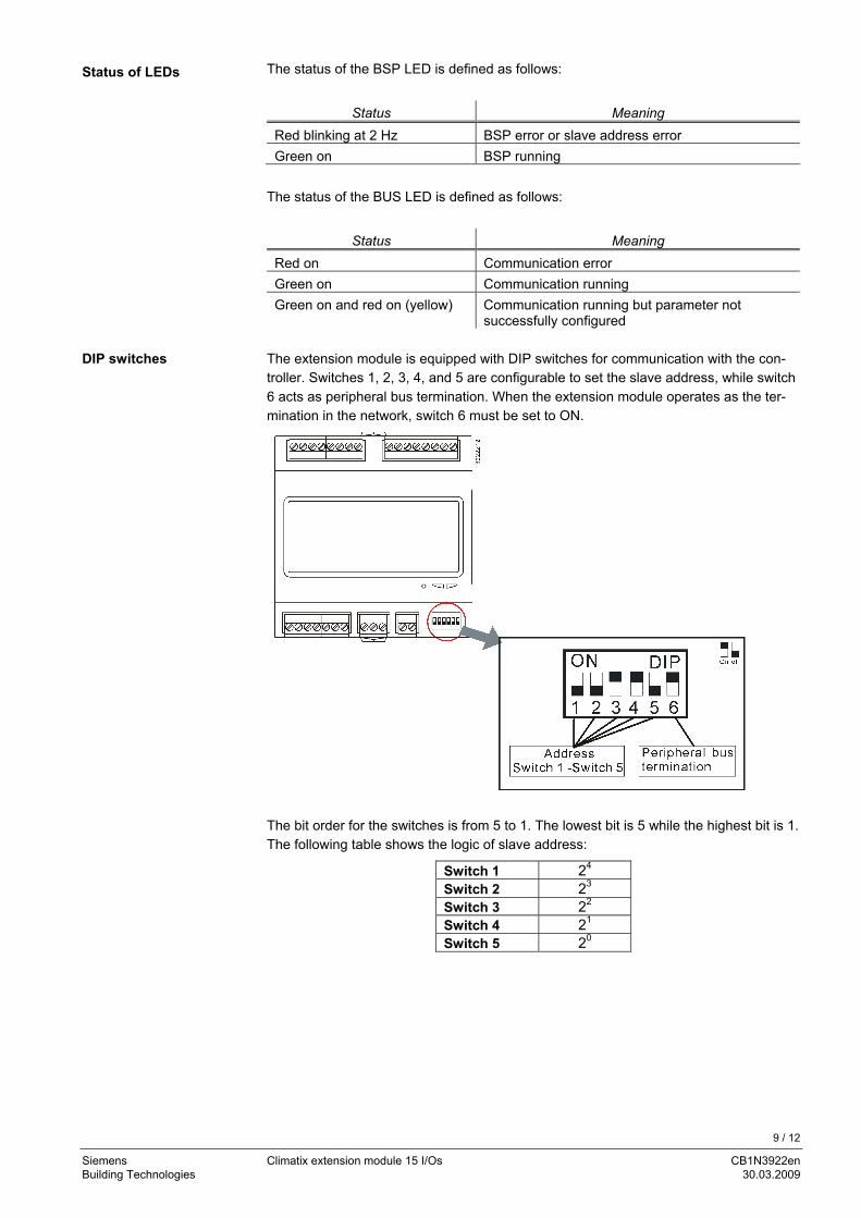
successfully configured The extension module is equipped with DIP switches for communication with the con-troller. Switches 1, 2, 3, 4, and 5 are configurable to set the slave address, while switch 6 acts as peripheral bus termination. When the extension module operates as the ter-mination in the network, switch 6 must be set to ON.
The bit order for the switches is from 5 to 1. The lowest bit is 5 while the highest bit is 1. The following table shows the logic of slave address:
Switch 1 24 Switch 2 23 Switch 3 22 Switch 4 21 Switch 5 20
Status of LEDs
DIP switches
10 / 12
Siemens Climatix extension module 15 I/Os CB1N3922en Building Technologies 30.03.2009
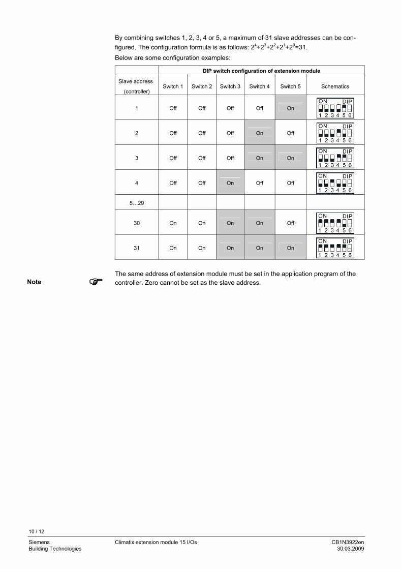
By combining switches 1, 2, 3, 4 or 5, a maximum of 31 slave addresses can be con-figured. The configuration formula is as follows: 24+23+22+21+20=31. Below are some configuration examples:
DIP switch configuration of extension module
Slave address
(controller) Switch 1 Switch 2 Switch 3 Switch 4 Switch 5 Schematics
1 Off Off Off Off On
2 Off Off Off On Off
3 Off Off Off On On
4 Off Off On Off Off
5…29
30 On On On On Off
31 On On On On On
The same address of extension module must be set in the application program of the controller. Zero cannot be set as the slave address.
Note
11 / 12
Siemens Climatix extension module 15 I/Os CB1N3922en Building Technologies 30.03.2009
Extension module 15 I/Os POL965.00/STD Connector set (spring cage, cable top entry) POL096.56/XXX
1 x Phoenix FKCT 2,5/2-ST GY7035 1 x Phoenix FKCT 2,5/3-ST KMGY 1 x Phoenix FKCT 2,5/7-ST GY7035 2 x Phoenix FKCT 2,5/8-ST GY7035 1 x Phoenix ZEC 1,0 / 4-LPV-3,5 GY35AUC2CI1 2 x Phoenix ZEC 1,0 / 4-ST-3,5 GY35AUC1R1,4
Engineering notes
To ensure protection against accidental contact with relay connections carrying voltages above 42 Veff, the module must be installed in an enclosure (preferably a control panel). It must be impossible to open the enclosure without the aid of a key or tool. AC 230 V cables must be double-insulated against safety extra low-voltage (SELV) cables.
Disposal notes
The module contains electrical and electronic components and must not be disposed of together with household waste.
Local and currently valid legislation must be observed!
Ordering data
Accessories
Warning
12 / 12
Siemens Climatix extension module 15 I/Os CB1N3922en Building Technologies 30.03.2009
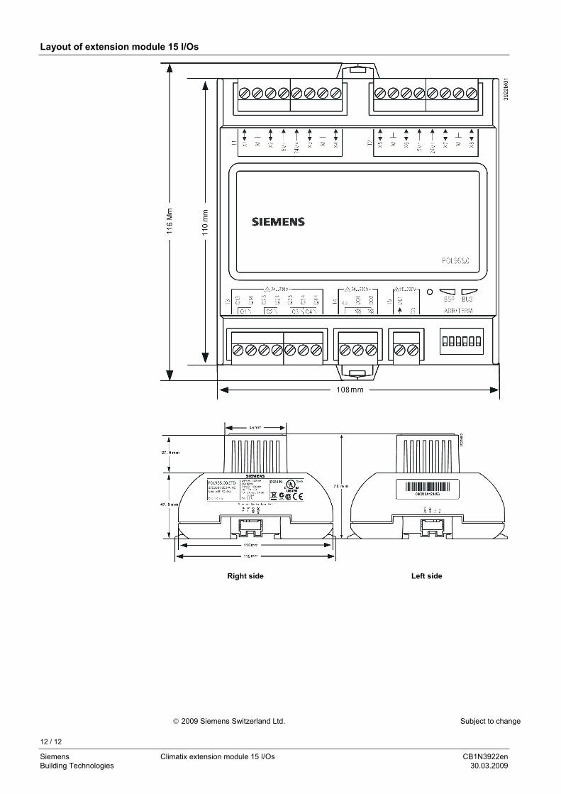
Layout of extension module 15 I/Os
Right side Left side
© 2009 Siemens Switzerland Ltd. Subject to change